MAE 6530, Propulsion Systems II Section 3.4 Static and Dynamic Stability, Longitudinal Pitch Dynamics 1

Welcome message from author
This document is posted to help you gain knowledge. Please leave a comment to let me know what you think about it! Share it to your friends and learn new things together.
Transcript

MAE 6530, Propulsion Systems II
Section 3.4Static and Dynamic Stability, Longitudinal
Pitch Dynamics
1

MAE 6530, Propulsion Systems II
Static Vs. Dynamic Stability
2
Static Stability
Dynamic Stability
Dynamic Stability

MAE 6530, Propulsion Systems II
Static Versus Dynamic Stability (2)
3
Static Instability Statically Stable,Dynamically Unstable
Static and DynamicallyStable

MAE 6530, Propulsion Systems II
Airframe Static Stability
4

MAE 6530, Propulsion Systems II
Airframe Dynamic Stability
5

MAE 6530, Propulsion Systems II
Center of Pressure
6
PitchingMoment
•Aerodynamic Lift, Drag, and Pitching Moment Can be though of acting at a single point … the Center of Pressure (CP) of the vehicle
•Sometimes (and not quite correctly) referred to as the Aerodynamic Center (AC)
•For our purposes applied to an axisymmetric rocket configuration, AC and CP are synonymous

MAE 6530, Propulsion Systems II
Center of Pressure
7

MAE 6530, Propulsion Systems II
Flight Vehicle Static Stability
8
• If center of gravity (cg) is forward of the Cp, vehicle responds to a disturbance by producing aerodynamic moment that returns Angle of attack of vehicle towards angle that existed prior to the disturbance. (static stability)
• If cg is behind the center of pressure, vehicle will respond to a disturbance by producing an aerodynamic moment that continues to drive angle of attack further away from starting position. (static instability)

MAE 6530, Propulsion Systems II
Static Stability, Rocket Flight Example
9
• During flight small wind gusts or thrust offsets cause the rocket to "wobble” … change attitude
• Rocket rotates about center of gravity (cg)• Lift and drag both act through center of pressure
(Cp)• When cp is behind cg, aerodynamic forces provide a
“restoring force” … rocket is said to be “statically stable”
• When Cp ahead of cg, aerodynamic forces provide a “destabilizing force” … rocket is said to be “unstable”
• Condition for a statically for a stable rocket is that center of pressure must be located behind longitudinal center of gravity.

MAE 6530, Propulsion Systems II
Static Stability, Rocket Flight Example (2)
10

MAE 6530, Propulsion Systems II
Static Stability, Rocket Flight Example (3)
11

MAE 6530, Propulsion Systems II
Weather Vane Analogy of Static Stability
12

MAE 6530, Propulsion Systems II
Static Margin and Pitching Moment
13
• Static margin used to characterize static stability and controllability of aircraft and missiles.
• For aircraft systems … Static margin defined as non-dimensional distance between center of gravity (cg) and aerodynamic center (ac) of the aircraft.
• For missile systems … Static margin defined as non-dimensional distance between center of gravity (cg) and the center of pressure (Cp).
• Static Stability requires that the pitching moment Cm about the rotation point, become negative as we increase CL:

MAE 6530, Propulsion Systems II
Pitching Moment Analysis
14
Cm0 à pitching moment about CpCm(a)à pitching moment about cgcref = “chord” reference length
Cm 0
α
α
Cm α( )=Cm0 +Xcg− XCpcreg
⎛
⎝
⎜⎜⎜⎜⎜
⎞
⎠
⎟⎟⎟⎟⎟⋅ CL ⋅cosα+CD ⋅sinα( )
→ Define ... Xsm =XCp− Xcgcreg
⎛
⎝
⎜⎜⎜⎜⎜
⎞
⎠
⎟⎟⎟⎟⎟→Cm α( )=Cm0 −Xsm ⋅ CL ⋅cosα+CD ⋅sinα( )
→ Linearize Pitching Moment Equation
... Cm α( )=Cm0+∂Cm∂α⋅α
Sum Moments abut cg
cref
cref

MAE 6530, Propulsion Systems II
Pitching Moment Analysis (2)
15
→ Define ... Cmα =∂Cm∂α=−Xsm ⋅
∂CL∂α⋅cosα−CL ⋅sinα+
∂CD∂α⋅sinα+CD ⋅sinα
⎛
⎝⎜⎜⎜⎜
⎞
⎠⎟⎟⎟⎟=
−Xsm ⋅ ∂CL∂α+CD
⎛
⎝⎜⎜⎜⎜
⎞
⎠⎟⎟⎟⎟⋅cosα− CL−
∂CD∂α
⎛
⎝⎜⎜⎜⎜
⎞
⎠⎟⎟⎟⎟⋅sinα
⎡
⎣⎢⎢⎢
⎤
⎦⎥⎥⎥
→ Neglect α2 term ... Cm α( )=Cm0−Xsm ⋅
∂CL∂α+CD
⎛
⎝⎜⎜⎜⎜
⎞
⎠⎟⎟⎟⎟⋅α
→ Small α approximation ... ∂Cm∂α=−Xsm ⋅
∂CL∂α+CD
⎛
⎝⎜⎜⎜⎜
⎞
⎠⎟⎟⎟⎟⋅α− CL−
∂CD∂α
⎛
⎝⎜⎜⎜⎜
⎞
⎠⎟⎟⎟⎟⋅α2
⎛
⎝⎜⎜⎜⎜
⎞
⎠⎟⎟⎟⎟⎟
→Cmα =∂Cm∂α=−Xsm ⋅
∂CL∂α+CD
⎛
⎝⎜⎜⎜⎜
⎞
⎠⎟⎟⎟⎟
CD ⋅cosα
→ Small α approximation ... ∂Cm∂α=−Xsm ⋅
∂CL∂α+CD
⎛
⎝⎜⎜⎜⎜
⎞
⎠⎟⎟⎟⎟⋅α− CL−
∂CD∂α
⎛
⎝⎜⎜⎜⎜
⎞
⎠⎟⎟⎟⎟⋅α2
⎛
⎝⎜⎜⎜⎜
⎞
⎠⎟⎟⎟⎟⎟
→ Small α approximation ... ∂Cm∂α=−Xsm ⋅
∂CL∂α+CD
⎛
⎝⎜⎜⎜⎜
⎞
⎠⎟⎟⎟⎟⋅α− CL−
∂CD∂α
⎛
⎝⎜⎜⎜⎜
⎞
⎠⎟⎟⎟⎟⋅α2
⎛
⎝⎜⎜⎜⎜
⎞
⎠⎟⎟⎟⎟⎟
→ Small α approximation ... ∂Cm∂α=−Xsm ⋅
∂CL∂α+CD
⎛
⎝⎜⎜⎜⎜
⎞
⎠⎟⎟⎟⎟⋅α− CL−
∂CD∂α
⎛
⎝⎜⎜⎜⎜
⎞
⎠⎟⎟⎟⎟⋅α2
⎛
⎝⎜⎜⎜⎜
⎞
⎠⎟⎟⎟⎟⎟
2

MAE 6530, Propulsion Systems II
Pitching Moment Analysis (3)
16
CL0
“Linear region”“Stall point”LinearAirfoilTheory
CD =CD0 +CL
2
π ⋅ε ⋅ Ar
CL =CL0 +∂CL∂α⋅α≡ CL0 +CL0 +
∂CL∂α⋅α
→∂CL∂αCD
⎡
⎣
⎢⎢⎢⎢⎢
⎤
⎦
⎥⎥⎥⎥⎥
>0
∂Cm
∂α→ "Cmα
".....Ideally...
Cmα= −Xsm
∂CL
∂α+ CD
⎛⎝⎜
⎞⎠⎟→
∂CL
∂αCD
⎡
⎣
⎢⎢
⎤
⎦
⎥⎥> 0→ Xsm > 0...
staticstability
→ Cmα< 0...
staticstability

MAE 6530, Propulsion Systems II
Pitching Moment Analysis (4)
17
For a Rocket Static margin is the distance between the CG and the CP; divided by body tube diameter.
17
∂Cm
∂α→ "Cmα
".....Ideally...
Cmα= −Xsm
∂CL
∂α+ CD
⎛⎝⎜
⎞⎠⎟→
∂CL
∂αCD
⎡
⎣
⎢⎢
⎤
⎦
⎥⎥> 0→ Xsm > 0...
staticstability
→ Cmα< 0...
staticstability

MAE 6530, Propulsion Systems II
Pitching Moment Analysis (6)
18
“Pike”
• Even Xsm > 0 (static stability) rockets become unstable at higher angles of attack
• “Strong stability” region limited to very low angle of attack range
stable
unstable
Cmα
α,deg.
stable

MAE 6530, Propulsion Systems II
Pitching Moment Analysis (5)
19

MAE 6530, Propulsion Systems II
Achieving Static Stability
20 20

MAE 6530, Propulsion Systems II
Static Margin = Degree of Static Stability
21 21

MAE 6530, Propulsion Systems II
How Much Static Stability?
22 22

MAE 6530, Propulsion Systems II
How Much Static Stability? (2)
23 23

MAE 6530, Propulsion Systems II
Calculating the Static Margin
24
•Key to calculating static margin is estimate of location of longitudinal center of pressure at low angles of attack •Barrowman equations provide simple, accurate technique for Axi-symmetric rockets•cg is measured as the longitudinal balance point of the rocket. •As a rule of thumb, Cp distance should be aft of the cg by at least one rocket diameter. -- "One Caliber stability”.

MAE 6530, Propulsion Systems II
Calculating the Static Margin (2)
25
N-- totalnormalFORCEn-- sectionalnormalpressuredifferential
…+transitions+boattail

MAE 6530, Propulsion Systems II
Calculating the Static Margin (3)
26
…+
…+transitions+boattail
=Nnose+ Ntail + Ntrns+ Nboat + ...
q ⋅ Aref=
CNnose +CNtail +CNtrns +CNboat + ...
CNαnose +CNαtail +CNαtrns +CNαboat + ...( )⋅α
of Nose, Fin &Transition Geometry
Stephen Whitmore

MAE 6530, Propulsion Systems II
Calculating the Static Margin (4)
27
max
maxmaximum body diameter

MAE 6530, Propulsion Systems II
Calculating the Static Margin (3)
28
(CNa)N=normalforcederivativefornose
(CNa)T=normalforcederivativefortransition
XN=centerofpressurelocationfornosesection
XT=centerofpressurelocationfortransitions
max max
a
a
Stephen Whitmore

MAE 6530, Propulsion Systems II
Calculating the Static Margin (4)
29
Static Margin (Xsm) =
(Xcp – Xcg)/dmax
Xcp
X – measured aft from nose of vehicle
(CNa)F=Normalforcederivativeforfingroup
(CNa)R=totalnormalforcederivative
XF=centerofpressurelocationforfingroups
max
a
a
a a a
a a a
a Small α→CNα ≅CLα
Stephen Whitmore

MAE 6530, Propulsion Systems II
Example: Stable Static Margin Vehicle
30
20 cm
10 cm
10 cm
8 cm
5 cm
30 cm
10 cm
5 cm
10 cm
12 cm
4 cm
16 cm
50 cm
3
OgiveNose
max
max
Stephen Whitmore

MAE 6530, Propulsion Systems II
Example: Unstable Static Margin Calculation
31
12.5 cm
5.54 cm
5.54 cm
5.54 cm
0 cm
12.5 cm
10 cm
0 cm
5.25 cm
6.5 cm
2.77 cm
9 cm
27 cm
3
OgiveNose
Constant diameter tube(No transition section)
max
max
Stephen Whitmore
Stephen Whitmore

MAE 6530, Propulsion Systems II
Rotational Dynamics of a Rigid Body.
32

p
q
r

MAE 6530, Propulsion Systems II
Simplified Pitch Axis Dynamics
33
Forcing moment
Second order Disturbance torque(neglected when r, p are small )
Neglect Cross Products of Inertia
Ix − Ixy − Ixz− Ixy I y − I yz− Ixz − I yz Iz
⎡
⎣
⎢⎢⎢⎢
⎤
⎦
⎥⎥⎥⎥
⋅
p.
q.
r.
⎡
⎣
⎢⎢⎢⎢⎢⎢
⎤
⎦
⎥⎥⎥⎥⎥⎥
=
q ⋅r I y − Iz( )+ q2 − r 2( ) I yz + p ⋅q Ixz( )− r ⋅ p Ixy( )r ⋅ p Iz − Ix( )+ r 2 − p2( ) Ixz + q ⋅r Ixy( )− p ⋅q I yz( )p ⋅q Ix − I y( )+ p2 − q2( ) Ixy + r ⋅ p I yz( )− q ⋅r Ixz( )
⎛
⎝
⎜⎜⎜⎜⎜
⎞
⎠
⎟⎟⎟⎟⎟
+
Mx
My
Mz
⎡
⎣
⎢⎢⎢⎢
⎤
⎦
⎥⎥⎥⎥
→ q.
= θ..
=My
I y+ r ⋅ p
Iz − Ix( )I y
GeneralRotationalDynamics
Stephen Whitmore
Stephen Whitmore

Collected Equations
Ixx −Ixy −Ixz
−Ixy I yy −I yz
−Ixz −I yz Izz
⎡
⎣
⎢⎢⎢⎢⎢⎢
⎤
⎦
⎥⎥⎥⎥⎥⎥
⋅
!p!q!r
⎡
⎣
⎢⎢⎢⎢⎢⎢
⎤
⎦
⎥⎥⎥⎥⎥⎥
=
I yy− Izz( )⋅q ⋅r+ I yz ⋅ q2−r 2( )+ Ixz ⋅ p ⋅q− Ixy ⋅ p ⋅r
Izz− Ixx( )⋅ p ⋅r+ Ixz ⋅ r 2− p2( )+ Ixy ⋅q ⋅r− I yz ⋅ p ⋅q
Ixx− I yy( )⋅ p ⋅q+ Ixy ⋅ p2−q2( )+ I yz ⋅ p ⋅r− Ixz ⋅q ⋅r
⎡
⎣
⎢⎢⎢⎢⎢⎢⎢
⎤
⎦
⎥⎥⎥⎥⎥⎥⎥
+
Mx
Ly
Nz
⎡
⎣
⎢⎢⎢⎢⎢⎢
⎤
⎦
⎥⎥⎥⎥⎥⎥
Principal Axes
I ≈ Real,symmetrix→ Find Axis Where→
Ixx −Ixy −Ixz
−Ixy I yy −I yz
−Ixz −I yz Izz
⎡
⎣
⎢⎢⎢⎢⎢⎢
⎤
⎦
⎥⎥⎥⎥⎥⎥
=U T ⋅Γ⋅U→Γ=
Ixx' 0 0
0 I yy' 0
0 0 Izz'
⎡
⎣
⎢⎢⎢⎢⎢⎢
⎤
⎦
⎥⎥⎥⎥⎥⎥
Euler 's Equations→ Ixy = Ixz = I yz = 0→ Simplify
Ixx ⋅ !p
I yy ⋅ !q
Izz ⋅ !r
⎡
⎣
⎢⎢⎢⎢⎢⎢
⎤
⎦
⎥⎥⎥⎥⎥⎥
=
I yy− Izz( )⋅q ⋅rIzz− Ixx( )⋅ p ⋅rIxx− I yy( )⋅ p ⋅q
⎡
⎣
⎢⎢⎢⎢⎢⎢⎢
⎤
⎦
⎥⎥⎥⎥⎥⎥⎥
+
Mx
Ly
Nz
⎡
⎣
⎢⎢⎢⎢⎢⎢
⎤
⎦
⎥⎥⎥⎥⎥⎥
→
!p=I yy− Izz
Ixx
⎛
⎝⎜⎜⎜⎜
⎞
⎠
⎟⎟⎟⎟⎟⋅q ⋅r+
Mx
Ixx
!q=Izz− Ixx
I yy
⎛
⎝
⎜⎜⎜⎜⎜
⎞
⎠
⎟⎟⎟⎟⎟⋅ p ⋅r+
Ly
I yy
!r=Ixx− I yy
Izz
⎛
⎝⎜⎜⎜⎜
⎞
⎠
⎟⎟⎟⎟⎟⋅ p ⋅q+
Nz
Izz
⎡
⎣
⎢⎢⎢⎢⎢⎢⎢⎢⎢⎢⎢⎢⎢⎢
⎤
⎦
⎥⎥⎥⎥⎥⎥⎥⎥⎥⎥⎥⎥⎥⎥
Collected Euler Equations
!p
!q
!r
!φ
!θ
!ψ
⎡
⎣
⎢⎢⎢⎢⎢⎢⎢⎢⎢⎢⎢⎢⎢⎢⎢⎢⎢⎢⎢⎢⎢⎢⎢⎢⎢
⎤
⎦
⎥⎥⎥⎥⎥⎥⎥⎥⎥⎥⎥⎥⎥⎥⎥⎥⎥⎥⎥⎥⎥⎥⎥⎥⎥
=
I yy− Izz
Ixx
⎛
⎝⎜⎜⎜⎜
⎞
⎠
⎟⎟⎟⎟⎟⋅q ⋅r
Izz− Ixx
I yy
⎛
⎝
⎜⎜⎜⎜⎜
⎞
⎠
⎟⎟⎟⎟⎟⋅ p ⋅r
Ixx− I yy
Izz
⎛
⎝⎜⎜⎜⎜
⎞
⎠
⎟⎟⎟⎟⎟⋅ p ⋅q
p+ tanθ ⋅sinφ ⋅q+ tanθ ⋅cosφ ⋅r
cosφ ⋅q−sinφ ⋅r
sinφcosθ
⋅q+ cosφcosθ
⋅r
⎡
⎣
⎢⎢⎢⎢⎢⎢⎢⎢⎢⎢⎢⎢⎢⎢⎢⎢⎢⎢⎢⎢⎢⎢⎢⎢⎢⎢⎢⎢⎢⎢⎢⎢⎢⎢⎢
⎤
⎦
⎥⎥⎥⎥⎥⎥⎥⎥⎥⎥⎥⎥⎥⎥⎥⎥⎥⎥⎥⎥⎥⎥⎥⎥⎥⎥⎥⎥⎥⎥⎥⎥⎥⎥⎥
+
Mx
Ixx
M y
I yy
Nz
Izz
0
0
0
⎡
⎣
⎢⎢⎢⎢⎢⎢⎢⎢⎢⎢⎢⎢⎢⎢⎢⎢⎢⎢⎢⎢⎢⎢⎢⎢⎢⎢⎢⎢⎢⎢⎢⎢
⎤
⎦
⎥⎥⎥⎥⎥⎥⎥⎥⎥⎥⎥⎥⎥⎥⎥⎥⎥⎥⎥⎥⎥⎥⎥⎥⎥⎥⎥⎥⎥⎥⎥⎥
+ disturbance torques
Stephen Whitmore
with no inertia cross products
Stephen Whitmore

MAE 6530, Propulsion Systems II
Simplified Pitch Axis Dynamics
33
Forcing moment
Second order Disturbance torque(neglected when r, p are small )
Neglect Cross Products of Inertia
Ix − Ixy − Ixz− Ixy I y − I yz− Ixz − I yz Iz
⎡
⎣
⎢⎢⎢⎢
⎤
⎦
⎥⎥⎥⎥
⋅
p.
q.
r.
⎡
⎣
⎢⎢⎢⎢⎢⎢
⎤
⎦
⎥⎥⎥⎥⎥⎥
=
q ⋅r I y − Iz( )+ q2 − r 2( ) I yz + p ⋅q Ixz( )− r ⋅ p Ixy( )r ⋅ p Iz − Ix( )+ r 2 − p2( ) Ixz + q ⋅r Ixy( )− p ⋅q I yz( )p ⋅q Ix − I y( )+ p2 − q2( ) Ixy + r ⋅ p I yz( )− q ⋅r Ixz( )
⎛
⎝
⎜⎜⎜⎜⎜
⎞
⎠
⎟⎟⎟⎟⎟
+
Mx
My
Mz
⎡
⎣
⎢⎢⎢⎢
⎤
⎦
⎥⎥⎥⎥
→ q.
= θ..
=My
I y+ r ⋅ p
Iz − Ix( )I y
GeneralRotationalDynamics
Stephen Whitmore

MAE 6530, Propulsion Systems II
Simplified Pitch Axis Dynamics (2)
34
θ = q =My
Iy→ My ≈ " pitching moment"
" pitching moment coefficient" ≡ Cm =My
q ⋅ Aref ⋅ cref
q =12⋅ ρ ⋅V 2⎛
⎝⎜⎞⎠⎟
Aref =π4⋅Dref
2
"reference length"→ cref ≈ Lrocket
Neglecting Disturbance torques
q ⋅ Aref ⋅ crefIy
Ntm2 ⋅m
2 ⋅m
kg ⋅m2
kg − msec2 m2 ⋅m
2 ⋅m⎛⎝⎜
⎞⎠⎟⋅
1kg ⋅m2
1sec2
Check Units
cref = Dmax
Stephen Whitmore
Consider Only Pitch Axis Dynamics for axi-symmetrix Missile

MAE 6530, Propulsion Systems II
Simplified Pitch Axis Dynamics (3)
35
q Cm 0
α
α
Gravity acts at cg andCannot induce pitching moment
Depends on angle of attack q =
q ⋅ Aref ⋅ crefIy
⋅Cm
Pitching moment about cg
Stephen Whitmore

MAE 6530, Propulsion Systems II
Simplified Pitch Axis Dynamics (4)
36
Depends on angle of attack +Control inputs
It can also be shown that … (NASA RP-1168 pp 10-22) that for angle of attack
α = −
q ⋅ Arefm ⋅V
⋅CL + q +g(r )Vcos θ −α( ) − Fthrust sinα
m ⋅V
θ = q =q ⋅ Aref ⋅ cref
Iy⋅Cm
SeeappendixIforderivation

MAE 6530, Propulsion Systems II
Collected, Simplified Longitudinal Axis-Dynamics (5)
37
αqθ
⎡
⎣
⎢⎢⎢
⎤
⎦
⎥⎥⎥=
−q ⋅ Arefm ⋅V
⋅CL + q +g(r )Vcos θ −α( ) − Fthrust sinα
m ⋅Vq ⋅ Aref ⋅ cref
Iy⋅Cm
q
⎡
⎣
⎢⎢⎢⎢⎢⎢⎢
⎤
⎦
⎥⎥⎥⎥⎥⎥⎥
Stephen Whitmore

MAE 6530, Propulsion Systems II
Linear Analysis of Longitudinal Axis-Dynamics
38
αqθ
⎡
⎣
⎢⎢⎢
⎤
⎦
⎥⎥⎥=
−q ⋅ Arefm ⋅V
⋅CL + q +g(r )Vcos θ −α( ) − Fthrust sinα
m ⋅Vq ⋅ Aref ⋅ cref
Iy⋅Cm
q
⎡
⎣
⎢⎢⎢⎢⎢⎢⎢
⎤
⎦
⎥⎥⎥⎥⎥⎥⎥
Start with
α → smallCL ≈CLα
⋅αCm ≈Cmα
⋅α +Cmq⋅q
q = !θ!q = !!θ
→!α!q!θ
⎡
⎣
⎢⎢⎢
⎤
⎦
⎥⎥⎥=
−q ⋅Aref ⋅CLα +Tthrust
m ⋅V∞
1 0
q ⋅Aref ⋅crefIy
⋅Cmα
q ⋅Aref ⋅crefIy
⋅Cmq0
0 1 0
⎡
⎣
⎢⎢⎢⎢⎢⎢⎢⎢
⎤
⎦
⎥⎥⎥⎥⎥⎥⎥⎥
⋅αqθ
⎡
⎣
⎢⎢⎢
⎤
⎦
⎥⎥⎥+
g ⋅cos θ( )V∞
00
⎡
⎣
⎢⎢⎢⎢⎢⎢
⎤
⎦
⎥⎥⎥⎥⎥⎥
Cmα→ "stability derivative"
Cmq→ "damping derivative"

MAE 6530, Propulsion Systems II
Linear Analysis (2)
39
Let & Reorder States …
!α!θ!!θ
⎡
⎣
⎢⎢⎢
⎤
⎦
⎥⎥⎥=
−q ⋅Aref ⋅CLα +Tthrust
m ⋅V∞
0 1
0 0 1q ⋅Aref ⋅cref
Iy⋅Cmα
0q ⋅Aref ⋅cref
Iy⋅Cmq
⎡
⎣
⎢⎢⎢⎢⎢⎢
⎤
⎦
⎥⎥⎥⎥⎥⎥
⋅αθ!θ
⎡
⎣
⎢⎢⎢
⎤
⎦
⎥⎥⎥+
g ⋅cos θ( )V∞
00
⎡
⎣
⎢⎢⎢⎢⎢⎢
⎤
⎦
⎥⎥⎥⎥⎥⎥
q = !θ!q = !!θ
!α!q!θ
⎡
⎣
⎢⎢⎢
⎤
⎦
⎥⎥⎥=
−q ⋅Aref ⋅CLα +Tthrust
m ⋅V∞
1 0
q ⋅Aref ⋅crefIy
⋅Cmα
q ⋅Aref ⋅crefIy
⋅Cmq0
0 1 0
⎡
⎣
⎢⎢⎢⎢⎢⎢⎢⎢
⎤
⎦
⎥⎥⎥⎥⎥⎥⎥⎥
⋅αqθ
⎡
⎣
⎢⎢⎢
⎤
⎦
⎥⎥⎥+
g ⋅cos θ( )V∞
00
⎡
⎣
⎢⎢⎢⎢⎢⎢
⎤
⎦
⎥⎥⎥⎥⎥⎥

MAE 6530, Propulsion Systems II
Linear Analysis (3)
40
Write as
Look at Eigenvalues of Linearized System
!X = A ⋅X +G(t)
!α!θ!!θ
⎡
⎣
⎢⎢⎢
⎤
⎦
⎥⎥⎥= ddt
αθ!θ
⎡
⎣
⎢⎢⎢
⎤
⎦
⎥⎥⎥→ X =
αθ!θ
⎡
⎣
⎢⎢⎢
⎤
⎦
⎥⎥⎥→ A =
−q ⋅Aref ⋅CLα +Tthrust
m ⋅V∞
0 1
0 0 1q ⋅Aref ⋅cref
Iy⋅Cmα
0q ⋅Aref ⋅cref
Iy⋅Cmq
⎡
⎣
⎢⎢⎢⎢⎢⎢
⎤
⎦
⎥⎥⎥⎥⎥⎥
→G(t) =
g ⋅cos θ( )V∞
00
⎡
⎣
⎢⎢⎢⎢⎢⎢
⎤
⎦
⎥⎥⎥⎥⎥⎥
Det A − λ ⋅ I[ ]= 0→
−q ⋅Aref ⋅CLα +Tthrust
m ⋅V∞
− λ 0 1
0 −λ 1q ⋅Aref ⋅cref
Iy⋅Cmα
0q ⋅Aref ⋅cref
Iy⋅Cmq
− λ
⎡
⎣
⎢⎢⎢⎢⎢⎢
⎤
⎦
⎥⎥⎥⎥⎥⎥
= 0

MAE 6530, Propulsion Systems II
Linear Analysis (4)
41
Det A − λ ⋅ I[ ]= 0→
−q ⋅Aref ⋅CLα +Tthrust
m ⋅V∞
− λ 0 1
0 −λ 1q ⋅Aref ⋅cref
Iy⋅Cmα
0q ⋅Aref ⋅cref
Iy⋅Cmq
− λ
⎡
⎣
⎢⎢⎢⎢⎢⎢
⎤
⎦
⎥⎥⎥⎥⎥⎥
= 0
Eigen Values
−q ⋅Aref ⋅CLα +Tthrust
m ⋅V∞
+ λ⎛⎝⎜
⎞⎠⎟⋅ λ 2 −
q ⋅Aref ⋅crefIy
⋅Cmq⋅λ
⎛
⎝⎜⎞
⎠⎟+
q ⋅Aref ⋅crefIy
⋅Cmα
⎛
⎝⎜⎞
⎠⎟⋅λ = 0
→ divide thru by − λ
λ +q ⋅Aref ⋅CLα +Tthrust
m ⋅V∞
⎛⎝⎜
⎞⎠⎟⋅ λ −
q ⋅Aref ⋅crefIy
⋅Cmq
⎛
⎝⎜⎞
⎠⎟−
q ⋅Aref ⋅crefIy
⋅Cmα
⎛
⎝⎜⎞
⎠⎟= 0

MAE 6530, Propulsion Systems II
Linear Analysis (4)
42
Expand and Collect Terms to give Characteristic Equation for Linearized System
→ divide thru by − λ
λ +q ⋅Aref ⋅CLα +Tthrust
m ⋅V∞
⎛⎝⎜
⎞⎠⎟⋅ λ −
q ⋅Aref ⋅crefIy
⋅Cmq
⎛
⎝⎜⎞
⎠⎟−
q ⋅Aref ⋅crefIy
⋅Cmα
⎛
⎝⎜⎞
⎠⎟= 0
λ 2 +q ⋅Aref ⋅CLα +Tthrust
m ⋅V∞
−q ⋅Aref ⋅cref
Iy⋅Cmq
⎛
⎝⎜⎞
⎠⎟⋅λ −
q ⋅Aref ⋅crefIy
⎛
⎝⎜⎞
⎠⎟⋅
q ⋅Aref ⋅CLα +Tthrustm ⋅V∞
⎛⎝⎜
⎞⎠⎟⋅Cmq
+Cmα
⎡
⎣⎢
⎤
⎦⎥ = 0
Form like :λ 2 + 2 ⋅ς ⋅ω n ⋅λ +ω n2 = 0
→ ω n = −q ⋅Aref ⋅cref
Iy
⎛
⎝⎜⎞
⎠⎟⋅
q ⋅Aref ⋅CLα +Tthrustm ⋅V∞
⎛⎝⎜
⎞⎠⎟⋅Cmq
+Cmα
⎡
⎣⎢
⎤
⎦⎥
2 ⋅ς ⋅ω n( )2ω n
2 → ς = 14
q ⋅Aref ⋅CLα +Tthrustm ⋅V∞
−q ⋅Aref ⋅cref
Iy⋅Cmq
⎛
⎝⎜⎞
⎠⎟
2
−q ⋅Aref ⋅cref
Iy
⎛
⎝⎜⎞
⎠⎟⋅
q ⋅Aref ⋅CLα +Tthrustm ⋅V∞
⎛⎝⎜
⎞⎠⎟⋅Cmq
+Cmα
⎡
⎣⎢
⎤
⎦⎥
NaturalFrequency
Dampingratio

MAE 6530, Propulsion Systems II
Estimating the Damping Derivatives
43
Small α→CNα≅CLα
→CN =CLα⋅
Xcp− Xcg
V∞
⎛
⎝⎜⎜⎜⎜
⎞
⎠
⎟⎟⎟⎟⎟⋅q
Cm =−CN ⋅Xcp− Xcg( )
cref
=−CLα⋅
Xcp− Xcg( )2
V∞
⎛
⎝
⎜⎜⎜⎜⎜⎜⎜
⎞
⎠
⎟⎟⎟⎟⎟⎟⎟⎟⋅
qcref
=−CLα⋅
Xcp− Xcg( )2
V∞cref2
⎛
⎝
⎜⎜⎜⎜⎜⎜⎜
⎞
⎠
⎟⎟⎟⎟⎟⎟⎟⎟⋅q ⋅cref =−CLα
⋅ Xsm2( )⋅ cref
V∞⋅q
δCm =∂Cm
∂q⋅q=Cmq
⋅q=−CLα⋅ Xsm
2( )⋅ cref
V∞⋅q→ Cmq
=−CLα⋅ Xsm
2( )⋅ cref
V∞
Cmq=−CLα
⋅ Xsm2( )⋅ cref
V∞→ pitch damping opposes motion ® i.e. always negative
q
Xcg
Xcp

MAE 6530, Propulsion Systems II
Collected Longitudinal Equations of Motion
44
Translational+rotational+mass
Can we simplify this “mess”?
Vr
Vν
r
ν
x
α
q
θm
⎡
⎣
⎢⎢⎢⎢⎢⎢⎢⎢⎢⎢⎢⎢⎢⎢⎢⎢⎢⎢⎢⎢⎢⎢⎢
⎤
⎦
⎥⎥⎥⎥⎥⎥⎥⎥⎥⎥⎥⎥⎥⎥⎥⎥⎥⎥⎥⎥⎥⎥⎥
=
Vν2
r⎛⎝⎜
⎞⎠⎟+
q ⋅ Arefm
⎛⎝⎜
⎞⎠⎟⋅ CL cosγ − CD sinγ( ) + Fthrust sinθ
m⎛⎝⎜
⎞⎠⎟− g(r )
−Vr ⋅Vν
r⎛⎝⎜
⎞⎠⎟−
q ⋅ Arefm
⎛⎝⎜
⎞⎠⎟⋅ CL sinγ + CD sinγ( ) + Fthrust cosθ
m⎛⎝⎜
⎞⎠⎟
Vr
Vν
r
Vν
−q ⋅ Arefm ⋅V
⋅CL + q +g(h)Vcos γ( ) − Fthrust sinα
m ⋅Vq ⋅ Aref ⋅ cref
Iy⋅Cm
q
−Fthrustg0 ⋅ Isp
⎡
⎣
⎢⎢⎢⎢⎢⎢⎢⎢⎢⎢⎢⎢⎢⎢⎢⎢⎢⎢⎢⎢⎢⎢⎢⎢⎢⎢⎢⎢⎢
⎤
⎦
⎥⎥⎥⎥⎥⎥⎥⎥⎥⎥⎥⎥⎥⎥⎥⎥⎥⎥⎥⎥⎥⎥⎥⎥⎥⎥⎥⎥⎥
→
g(r ) =µr2
γ = tan−1 VrVν
= θ −α
x = r ⋅ ν
V = Vr2 +Vυ
2
q =12⋅ ρ h( ) ⋅V
2
h = r − Rearth
Stephen Whitmore

MAE 6530, Propulsion Systems II
Simplified Longitudinal Equations of Motion
45
Translational+rotational+mass
αqθ
⎡
⎣
⎢⎢⎢
⎤
⎦
⎥⎥⎥=
−q ⋅ Arefm ⋅V
⋅CL + q +g(r )Vcos θ −α( ) − Fthrust sinα
m ⋅Vq ⋅ Aref ⋅ cref
Iy⋅Cm
q
⎡
⎣
⎢⎢⎢⎢⎢⎢⎢
⎤
⎦
⎥⎥⎥⎥⎥⎥⎥
Augment with longitudinal Acceleration Equation (See Appendix II)
Complete with altitude and downrange!h=V∞ ⋅sinγ=V∞ ⋅sin θ−α( )!x=V∞ ⋅cosγ=V∞ ⋅cos θ−α( )
!V∞ =Tthrust ⋅cosα
m−g ⋅sin θ−α( )−
q ⋅ Aref ⋅CDm

MAE 6530, Propulsion Systems II
!V∞
!α
!θ!q
!h!x
!m
⎡
⎣
⎢⎢⎢⎢⎢⎢⎢⎢⎢⎢⎢⎢⎢⎢⎢⎢⎢⎢⎢⎢⎢⎢⎢⎢⎢
⎤
⎦
⎥⎥⎥⎥⎥⎥⎥⎥⎥⎥⎥⎥⎥⎥⎥⎥⎥⎥⎥⎥⎥⎥⎥⎥⎥
=
Tthrust ⋅cosαm
−g ⋅sin θ−α( )−q ⋅ Aref ⋅CD
m
!α= q+g ⋅cos θ−α( )
V∞−q ⋅ Aref ⋅CL+Tthrust ⋅sinα
m⋅V∞q
q ⋅ Aref ⋅cref ⋅CmI yy
V∞ sin θ−α( )V∞ cos θ−α( )
−Tthrustg0 ⋅ Isp
⎡
⎣
⎢⎢⎢⎢⎢⎢⎢⎢⎢⎢⎢⎢⎢⎢⎢⎢⎢⎢⎢⎢⎢⎢⎢⎢⎢
⎤
⎦
⎥⎥⎥⎥⎥⎥⎥⎥⎥⎥⎥⎥⎥⎥⎥⎥⎥⎥⎥⎥⎥⎥⎥⎥⎥
Simplified Longitudinal Equations of Motion
46
Translational+rotational+mass
Collected Body-Axis Equations
CL =CL α( )!CNα ⋅α
Cm =Cm α,q( )≈Cmα ⋅α+Cmq ⋅q=
−Xsm ⋅ CNα +CD( )⋅α− Xsm2 ⋅ CNα ⋅crefV∞
⎛
⎝⎜⎜⎜⎜
⎞
⎠
⎟⎟⎟⎟⎟⋅q

MAE 6530, Propulsion Systems II
Model Comparison
47
BodyAxiswithPitchDynamicsModelLocalVertical/LocalHorizontalBallisticModelOneextradegreeoffreedom
!V∞
!α
!θ!q
!h!x
!m
⎡
⎣
⎢⎢⎢⎢⎢⎢⎢⎢⎢⎢⎢⎢⎢⎢⎢⎢⎢⎢⎢⎢⎢⎢⎢⎢⎢
⎤
⎦
⎥⎥⎥⎥⎥⎥⎥⎥⎥⎥⎥⎥⎥⎥⎥⎥⎥⎥⎥⎥⎥⎥⎥⎥⎥
=
Tthrust ⋅cosαm
−g ⋅sin θ−α( )−q ⋅ Aref ⋅CD
m
!α= q+g ⋅cos θ−α( )
V∞−q ⋅ Aref ⋅CL+Tthrust ⋅sinα
m⋅V∞q
q ⋅ Aref ⋅cref ⋅CmI yy
V∞ sin θ−α( )V∞ cos θ−α( )
−Tthrustg0 ⋅ Isp
⎡
⎣
⎢⎢⎢⎢⎢⎢⎢⎢⎢⎢⎢⎢⎢⎢⎢⎢⎢⎢⎢⎢⎢⎢⎢⎢⎢
⎤
⎦
⎥⎥⎥⎥⎥⎥⎥⎥⎥⎥⎥⎥⎥⎥⎥⎥⎥⎥⎥⎥⎥⎥⎥⎥⎥

MAE 6530, Propulsion Systems II
Example Calculation
48

MAE 6530, Propulsion Systems II
Example Calculation (2)
49

MAE 6530, Propulsion Systems II
Example Calculation (2)
50
Fin Coefficients
= 1 1010 35+( )
+⎝ ⎠⎛ ⎞
4 3535⎝ ⎠
⎛ ⎞ 2
1 1 2 36.8091·25 8.67923+⎝ ⎠
⎛ ⎞ 2+⎝ ⎠⎜ ⎟⎛ ⎞ 0.5
+⎝ ⎠⎜ ⎟⎜ ⎟⎜ ⎟⎜ ⎟⎛ ⎞
3 =4.30898
Barrowman …
Helmbold …
×N fins
2= = 4.29281
AR= LF2
Afin=36.80912
589.387= 2.29885
2π2.29885
2 2.298852 4+( ) 0.5+
32

MAE 6530, Propulsion Systems II
Effective CL for 4 Fin
Configuration
51

MAE 6530, Propulsion Systems II
Effective CL for 4 Fin
Configuration
52
w⋅cosφ→αN =w⋅cosφu
=α ⋅cosφ
CL =CNα ⋅cosφ ⋅α ⋅cosφ=CN ⋅cos2φ
αN =w⋅sinφu=α ⋅sinφ
CL =CNα ⋅sinφ ⋅α ⋅sinφ=CN ⋅sin2φ
CLeffective = CL i∑ =CN ⋅cos2φ+CN ⋅sin
2φ+CN ⋅sin2φ+CN ⋅cos
2φ
= 2 ⋅CN ⋅ cos2φ+ sin2φ( )
→ CLeffective =12⋅N ⋅CN → N = 4

MAE 6530, Propulsion Systems II
Effective CL for 3 Fin
Configuration
53

MAE 6530, Propulsion Systems II
Effective CL for 3 Fin
Configuration
54
CL =CNα ⋅cos φ+300( )⋅α ⋅cos φ+300( )=CN ⋅cos2 φ+300( )
CL =CNα ⋅cos φ−300( )⋅α ⋅cos φ−300( )=CN ⋅cos2 φ−300( )
CLeffective = CL i∑ =CN ⋅cos2 φ+300( )+CN ⋅cos2 φ−300( )+CN ⋅sin2φ
cos2 φ+300( )= cosφcos300−sinφsin300( )2 = 32cosφ− 1
2sinφ
⎛
⎝
⎜⎜⎜⎜⎜
⎞
⎠
⎟⎟⎟⎟⎟
2
=34cos2φ− 3
2cosφsinφ+ 1
4sin2φ
cos2 φ−300( )= cosφcos300+ sinφsin300( )2 = 32cosφ+ 1
2sinφ
⎛
⎝
⎜⎜⎜⎜⎜
⎞
⎠
⎟⎟⎟⎟⎟
2
=34cos2φ+ 3
2cosφsinφ+ 1
4sin2φ
CL i∑ =CN ⋅ sin2φ+
34cos2φ− 3
2cosφsinφ+ 1
4sin2φ+ 3
4cos2φ+ 3
2cosφsinφ+ 1
4sin2φ
⎛
⎝
⎜⎜⎜⎜⎜
⎞
⎠
⎟⎟⎟⎟⎟=32CN ⋅ sin
2φ+cos2φ( )= 32CN
CLeffective =N2CN → N = 3 QED!

MAE 6530, Propulsion Systems II
Example Calculation (3)
55
Total parameter calculation
=-6.44348
CLα ≈CNR
Cmα =−Xsm ⋅ CLα +CD0( )=
Cmq( )0=−Xsm
2 ⋅CLα ⋅crefV∞0
⎛
⎝⎜⎜⎜⎜
⎞
⎠
⎟⎟⎟⎟⎟=
1.22093 4.96204 0.315467+( )−
1.220932 4.96204( )−( )67.2868
35100
=-0.038475

MAE 6530, Propulsion Systems II
Launch Simulation with Pitch
56
I yy( )0= M0 ⋅L
2 =105.87 ⋅2.152 = 506.373kg−m2
Target 10,000 M Apogee altitude

MAE 6530, Propulsion Systems II
Example Calculation, Pitch Sim
57

MAE 6530, Propulsion Systems II
Example Calculation, Pitch Sim (2)
58
MAE 6530, Propulsion Systems II
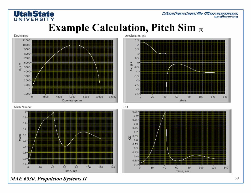
Example Calculation, Pitch Sim (3)
59

MAE 6530, Propulsion Systems II
Simulation Comparisons
60

MAE 6530, Propulsion Systems II
Pitching Moment Control
M y =q ⋅ Aref ⋅cref
I yy
Cm =q ⋅ Aref ⋅cref
I yy
Cm α,q( )+Cmd⋅δ( )
Natural Response Controlled Response Depends on α, q Depends on Actuation
Pitching Moment Control of Vehicle
61
αqθ
⎡
⎣
⎢⎢⎢
⎤
⎦
⎥⎥⎥=
−q ⋅ Arefm ⋅V
⋅CL + q +g(r )Vcos θ −α( ) − Fthrust sinα
m ⋅Vq ⋅ Aref ⋅ cref
Iy⋅Cm
q
⎡
⎣
⎢⎢⎢⎢⎢⎢⎢
⎤
⎦
⎥⎥⎥⎥⎥⎥⎥

MAE 6530, Propulsion Systems II
Launch (Rocket) Controls
62

MAE 6530, Propulsion Systems II
Decoupled Equations of Motion
63
Vr
Vν
r
ν
x
α
q
θm
⎡
⎣
⎢⎢⎢⎢⎢⎢⎢⎢⎢⎢⎢⎢⎢⎢⎢⎢⎢⎢⎢⎢⎢⎢⎢
⎤
⎦
⎥⎥⎥⎥⎥⎥⎥⎥⎥⎥⎥⎥⎥⎥⎥⎥⎥⎥⎥⎥⎥⎥⎥
=
Vν2
r⎛⎝⎜
⎞⎠⎟+
q ⋅ Arefm
⎛⎝⎜
⎞⎠⎟⋅ CL cosγ − CD sinγ( ) + Fthrust sinθ
m⎛⎝⎜
⎞⎠⎟− g(r )
−Vr ⋅Vν
r⎛⎝⎜
⎞⎠⎟−
q ⋅ Arefm
⎛⎝⎜
⎞⎠⎟⋅ CL sinγ + CD sinγ( ) + Fthrust cosθ
m⎛⎝⎜
⎞⎠⎟
Vr
Vν
r
Vν
−q ⋅ Arefm ⋅V
⋅CL + q +g(h)Vcos γ( ) − Fthrust sinα
m ⋅Vq ⋅ Aref ⋅ cref
Iy⋅Cm
q
−Fthrustg0 ⋅ Isp
⎡
⎣
⎢⎢⎢⎢⎢⎢⎢⎢⎢⎢⎢⎢⎢⎢⎢⎢⎢⎢⎢⎢⎢⎢⎢⎢⎢⎢⎢⎢⎢
⎤
⎦
⎥⎥⎥⎥⎥⎥⎥⎥⎥⎥⎥⎥⎥⎥⎥⎥⎥⎥⎥⎥⎥⎥⎥⎥⎥⎥⎥⎥⎥
→
g(r ) =µr2
γ = tan−1 VrVν
= θ −α
x = r ⋅ ν
V = Vr2 +Vυ
2
q =12⋅ ρ h( ) ⋅V
2
h = r − Rearth
OuterLoop
• Very loose coupling between longitudinal aerodynamics and pitch dynamics and overall vehicle trajectory
• Generally pitch dynamics and vehicle trajectory are controlled independently
• Trajectory controlled about somePrescribed q0(t) (outer loop)
• Pitch tracking controlled about nominal q0(t) (inner loop)
InnerLoop

MAE 6530, Propulsion Systems II
Example Control Strategies
64

MAE 6530, Propulsion Systems II 65
Questions??

MAE 6530, Propulsion Systems II
Appendix I: Derivation of the Longitudinal “AlphaDot” Equation
66
• Body Axis Coordinates, Position and Airspeed Components
y, v
x, u
z, wz, w
y, v
!V∞ = u ⋅
!i + v ⋅
!j +w ⋅
!k ≡
uvw
⎡
⎣
⎢⎢⎢
⎤
⎦
⎥⎥⎥

MAE 6530, Propulsion Systems II
Derivation of the Longitudinal “AlphaDot” Equation (2)
67
• Body Axis Coordinates, Angular Rate Components
x
y
z
p
q
r
!V∞
!Ω = p ⋅
!i + q ⋅
!j + r ⋅
!k ≡
pqr
⎡
⎣
⎢⎢⎢
⎤
⎦
⎥⎥⎥

MAE 6530, Propulsion Systems II
Derivation of the Longitudinal “AlphaDot” Equation (3)
68
• Euler Anglesx
y
z
pqr
⎡
⎣
⎢⎢⎢
⎤
⎦
⎥⎥⎥=
!φ00
⎡
⎣
⎢⎢⎢
⎤
⎦
⎥⎥⎥+
1 0 00 cosφ sinφ0 −sinφ cosφ
⎡
⎣
⎢⎢⎢
⎤
⎦
⎥⎥⎥⋅0!θ0
⎡
⎣
⎢⎢⎢
⎤
⎦
⎥⎥⎥+
1 0 00 cosφ sinφ0 −sinφ cosφ
⎡
⎣
⎢⎢⎢
⎤
⎦
⎥⎥⎥⋅cosθ 0 −sinθ0 1 0sinθ 0 cosθ
⎡
⎣
⎢⎢⎢
⎤
⎦
⎥⎥⎥⋅
00!ψ
⎡
⎣
⎢⎢⎢
⎤
⎦
⎥⎥⎥
=1 0 −sinφ0 cosφ cosθ sinφ0 −sinφ cosθ cosφ
⎡
⎣
⎢⎢⎢
⎤
⎦
⎥⎥⎥⋅
!φ!θ!ψ
⎡
⎣
⎢⎢⎢⎢
⎤
⎦
⎥⎥⎥⎥
=
!φ − sinφ ⋅ !ψcosφ ⋅ !θ + cosθ sinφ ⋅ !ψ−sinφ ⋅ !θ + cosθ cosφ ⋅ !ψ
⎡
⎣
⎢⎢⎢⎢
⎤
⎦
⎥⎥⎥⎥
Earth-FixedCoordinates
!φ!θ!ψ
⎡
⎣
⎢⎢⎢⎢⎢⎢
⎤
⎦
⎥⎥⎥⎥⎥⎥
=
1 tanθsinφ tanθcosφ0 cosφ −sinφ0 sinφ cosθ cosφ cosθ
⎡
⎣
⎢⎢⎢⎢⎢⎢
⎤
⎦
⎥⎥⎥⎥⎥⎥
⋅
pqr
⎡
⎣
⎢⎢⎢⎢⎢⎢
⎤
⎦
⎥⎥⎥⎥⎥⎥
=
p+q ⋅ tanθsinφ+ r ⋅ tanθcosφq ⋅cosφ−r ⋅sinφ
q ⋅sinφ cosθ+ r ⋅cosφ cosθ
⎡
⎣
⎢⎢⎢⎢⎢⎢
⎤
⎦
⎥⎥⎥⎥⎥⎥

MAE 6530, Propulsion Systems II
Derivation of the Longitudinal “AlphaDot” Equation (4)
69
• From Dynamics
• Evaluating Cross Product
!Fm
=!A = d
dt!V( )+ !Ω×
!V → 1
m
FxFyFz
⎡
⎣
⎢⎢⎢⎢
⎤
⎦
⎥⎥⎥⎥
= ddt
uvw
⎛
⎝
⎜⎜
⎞
⎠
⎟⎟ +
!i!j!k
p q ru v w
→"u"v"w
⎡
⎣
⎢⎢⎢
⎤
⎦
⎥⎥⎥= −
!i!j!k
p q ru v w
+ 1m
FxFyFz
⎡
⎣
⎢⎢⎢⎢
⎤
⎦
⎥⎥⎥⎥
!u!v!w
⎡
⎣
⎢⎢⎢
⎤
⎦
⎥⎥⎥=
0 r −q−r 0 pq − p 0
⎡
⎣
⎢⎢⎢
⎤
⎦
⎥⎥⎥⋅
uvw
⎡
⎣
⎢⎢⎢
⎤
⎦
⎥⎥⎥+ 1m
FxFyFz
⎡
⎣
⎢⎢⎢⎢
⎤
⎦
⎥⎥⎥⎥

MAE 6530, Propulsion Systems II
Derivation of the Longitudinal “AlphaDot” Equation (5)
70
• Assume Axi-Symmetric Missile Profile, 2-D Flight Path
• Translational EOM Reduce to
(v, β, Fy = 0, V∞ = u2 + w2 )
V∞ = u2 +w2 →!u = -q ⋅w + Fx
m
w = q ⋅u + Fzm
⎡
⎣
⎢⎢⎢⎢
⎤
⎦
⎥⎥⎥⎥
!V∞
u
w
→ From Kinematics
tanα = wu→ 1+ tan2α( ) !α =
!wu− wu2
⋅ !u = !w ⋅u − !u ⋅wu2
1+ tan2α( ) = 1+ wu
⎛⎝⎜
⎞⎠⎟2⎛
⎝⎜⎞
⎠⎟= u
2 +w2
u2→ !α = u2
u2 +w2 ⋅!w ⋅u − !u ⋅w
u2=!w ⋅u − !u ⋅wu2 +w2
!α =!w ⋅u − !u ⋅wu2 +w2 =
!w ⋅uu2 +w2 −
!u ⋅wu2 +w2
!u= -q ⋅w+Fxm
!w= q ⋅u+Fzm
⎡
⎣
⎢⎢⎢⎢⎢⎢
⎤
⎦
⎥⎥⎥⎥⎥⎥

MAE 6530, Propulsion Systems II
Derivation of the Longitudinal “AlphaDot” Equation (6)
71
!V∞
u
w
→ From Kinematics
!α =!w ⋅u − !u ⋅wu2 +w2 =
!w ⋅uu2 +w2 −
!u ⋅wu2 +w2
→ From Dynamics
!u = -q ⋅w + Fxm
w = q ⋅u + Fzm
⎡
⎣
⎢⎢⎢⎢
⎤
⎦
⎥⎥⎥⎥
→ Substitute
!α =q ⋅u + Fz
m⎛⎝⎜
⎞⎠⎟ ⋅u
V∞2 −
-q ⋅w + Fxm
⎛⎝⎜
⎞⎠⎟ ⋅w
V∞2 =
q ⋅u2 + Fzm⋅u + q ⋅w2 − Fx
m⋅w⎛
⎝⎜⎞⎠⎟
V∞2 =
q ⋅ u2 +w2( )+ Fzm ⋅u + − Fxm
⋅w⎛⎝⎜
⎞⎠⎟
V∞2
→ Simplify
!α =q ⋅V∞
2 + Fzm⋅u + − Fx
m⋅w⎛
⎝⎜⎞⎠⎟
V∞2 =
q ⋅V∞2 + Fz
m⋅u + − Fx
m⋅w⎛
⎝⎜⎞⎠⎟
V∞2 = q +
Fzm ⋅V∞
⋅ uV∞
− Fxm ⋅V∞
⋅ wV∞
⎛⎝⎜
⎞⎠⎟
!u= -q ⋅w+Fxm
!w= q ⋅u+Fzm
⎡
⎣
⎢⎢⎢⎢⎢⎢
⎤
⎦
⎥⎥⎥⎥⎥⎥

MAE 6530, Propulsion Systems II
Derivation of the Longitudinal “AlphaDot” Equation (7)
72
Thrust
a
Lift
Drag
x
z
inematics
→
uV∞
= cosα
wV∞
= sinα
⎡
⎣
⎢⎢⎢⎢⎢
⎤
⎦
⎥⎥⎥⎥⎥
→ !α = q +Fz
m ⋅V∞
⋅cosα − Fxm ⋅V∞
⋅sinα⎛⎝⎜
⎞⎠⎟
→ Resolving ForcesFx = Tthrust −m ⋅g ⋅sinθ − Drag ⋅cosα + Lift ⋅sinαFz = m ⋅g ⋅cosθ − Drag ⋅sinα − Lift ⋅cosα⎡
⎣⎢
⎤
⎦⎥
→ Substituting
!α = q +m ⋅g ⋅cosθ − Drag ⋅sinα − Lift ⋅cosα
m ⋅V∞
⋅cosα −Tthrust −m ⋅g ⋅sinθ − Drag ⋅cosα + Lift ⋅sinα
m ⋅V∞
⋅sinα⎛⎝⎜
⎞⎠⎟

MAE 6530, Propulsion Systems II
Derivation of the Longitudinal “AlphaDot” Equation (7)
73
Thrust
a
Lift
Drag
x
z
CL =Lift
12⋅ρ ⋅V 2 ⋅ Aref
, CD =Drag
12⋅ρ ⋅V 2 ⋅ Aref
CL = lift coefficient, CD = drag coefficient
12⋅ρ ⋅V 2 = "dynamic pressure"(q )
Aref = "reference area"− > typically maximum frontal area
ρ = "local air density"− > function of altitude
→Collecting
!α = q + m ⋅g ⋅cosθ ⋅cosα +m ⋅g ⋅sinθ ⋅sinαm ⋅V∞
+−Drag ⋅sinα ⋅cosα + Drag ⋅cosα ⋅sinα
m ⋅V∞
−Lift ⋅cos
2α + Lift ⋅cos2α
m ⋅V∞
− Tthrust ⋅sinαm ⋅V∞
→ Simplifying
!α = q + g ⋅cos θ −α( )V∞
−Liftm ⋅V∞
− Tthrust ⋅sinαm ⋅V∞
→→ !α = q + g ⋅cos θ −α( )V∞
−q ⋅Aref ⋅CL +Tthrust ⋅sinα
m ⋅V∞
MAE 6530, Propulsion Systems II
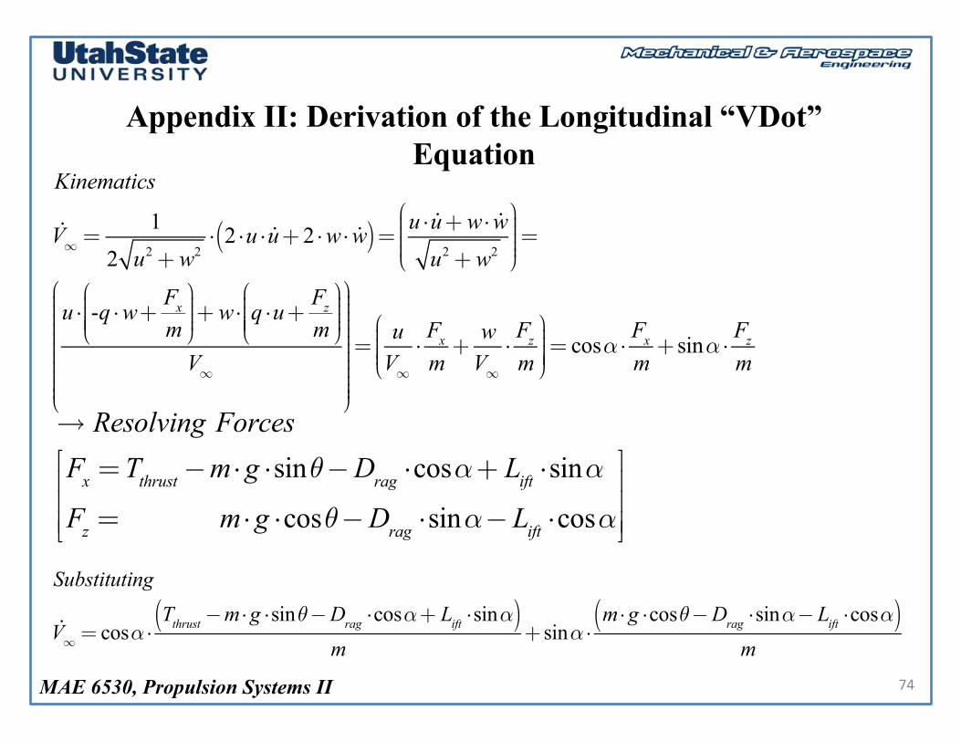
Appendix II: Derivation of the Longitudinal “VDot” Equation
74
Kinematics
!V∞ =1
2 u2+w2⋅ 2 ⋅u ⋅ !u+2 ⋅w⋅ !w( )= u ⋅ !u+w⋅ !w
u2+w2
⎛
⎝⎜⎜⎜⎜
⎞
⎠
⎟⎟⎟⎟⎟=
u ⋅ -q ⋅w+Fxm
⎛
⎝⎜⎜⎜⎜
⎞
⎠⎟⎟⎟⎟+w⋅ q ⋅u+
Fzm
⎛
⎝⎜⎜⎜⎜
⎞
⎠⎟⎟⎟⎟
V∞
⎛
⎝
⎜⎜⎜⎜⎜⎜⎜⎜⎜⎜⎜
⎞
⎠
⎟⎟⎟⎟⎟⎟⎟⎟⎟⎟⎟⎟⎟
=uV∞⋅Fxm+wV∞⋅Fzm
⎛
⎝⎜⎜⎜⎜
⎞
⎠⎟⎟⎟⎟⎟= cosα ⋅
Fxm+ sinα ⋅
Fzm
→ Resolving Forces
Fx =Tthrust−m⋅g ⋅sinθ−Drag ⋅cosα+ Lift ⋅sinα
Fz = m⋅g ⋅cosθ−Drag ⋅sinα− Lift ⋅cosα
⎡
⎣
⎢⎢⎢
⎤
⎦
⎥⎥⎥
Substituting
!V∞ = cosα ⋅Tthrust−m⋅g ⋅sinθ−Drag ⋅cosα+ Lift ⋅sinα( )
m+ sinα ⋅
m⋅g ⋅cosθ−Drag ⋅sinα− Lift ⋅cosα( )m

MAE 6530, Propulsion Systems II
Derivation of the Longitudinal “VDot” Equation
75
Simplifying
!V∞ = cosα ⋅Tthrust−m⋅g ⋅sinθ−Drag ⋅cosα( )
m+ sinα ⋅
m⋅g ⋅cosθ−Drag ⋅sinα( )m
=
!V∞ = cosα ⋅Tthrust−m⋅g ⋅sinθ−Drag ⋅cos
2α( )m
+ sinα ⋅m⋅g ⋅cosθ−Drag ⋅sin
2α( )m
=
Tthrust ⋅cosαm
+ g ⋅ cosθsinα−sinθcosα( )−Dragm
cos2α+ sin2α( )=Tthrust ⋅cosα
m+ g ⋅ cosθsinα−sinθcosα( )−
q ⋅ Aref ⋅CDm
=−q ⋅ Aref ⋅CD
m−g ⋅sin θ−α( )+ Tthrust ⋅cosα
m
!V∞ =Tthrust ⋅cosα
m−g ⋅sin θ−α( )−
q ⋅ Aref ⋅CDm
Related Documents