PRESTRESSED CIRCULAR CONCRETE RESERVOIRS 331620-1 60187814 - 18 Dec 2017 (S331620-NT.DOC) SECTION 331620 PRESTRESSED CIRCULAR CONCRETE RESERVOIRS PART 1 - GENERAL 1.01 DESCRIPTION This section describes materials and construction of prestressed circular concrete reservoirs. Contractor may select either a concrete roof or aluminum geodesic dome. 1.02 RELATED WORK SPECIFIED ELSEWHERE A. General Concrete Construction: 030500. B. Leakage Testing of Hydraulic Structures: 030510. C. Ladders, Stairs, and Stair Nosings: 055100. D. Handrails and Safety Chains: 055200. E. Grating, Cover Plates, and Access Hatches: 055300. F. Painting and Coating: 099000. G. Aluminum Geodesic Domes: 133310. 1.03 DESIGN INFORMATION Data 1. Nominal capacity 3 MG 2. Maximum water depth for overflow (above floor at wall) 37 feet, diameter = 118 feet 3. Free-board below top of wall to high water level 3 feet 4. Backfill height (above floor at wall) 20 feet (see drawings) 5. Equivalent liquid backfill pressure (static--at rest) 0 psf at F.G., 60 x H psf at reservoir bottom 6. Equivalent liquid backfill pressure (dynamic) on wall (add to static pressure) 0 psf at F.G. and bottom 10 x reservoir H applied at 0 H 7. Downward drag coefficient of backfill on wall 0.30

Welcome message from author
This document is posted to help you gain knowledge. Please leave a comment to let me know what you think about it! Share it to your friends and learn new things together.
Transcript
PRESTRESSED CIRCULAR CONCRETE RESERVOIRS 331620-1 60187814 - 18 Dec 2017 (S331620-NT.DOC)
SECTION 331620 PRESTRESSED CIRCULAR CONCRETE RESERVOIRS
PART 1 - GENERAL
1.01 DESCRIPTION
This section describes materials and construction of prestressed circular concrete reservoirs. Contractor may select either a concrete roof or aluminum geodesic dome.
1.02 RELATED WORK SPECIFIED ELSEWHERE
A. General Concrete Construction: 030500.
B. Leakage Testing of Hydraulic Structures: 030510.
C. Ladders, Stairs, and Stair Nosings: 055100.
D. Handrails and Safety Chains: 055200.
E. Grating, Cover Plates, and Access Hatches: 055300.
F. Painting and Coating: 099000.
G. Aluminum Geodesic Domes: 133310.
1.03 DESIGN INFORMATION
Data
1. Nominal capacity 3 MG
2. Maximum water depth for overflow (above floor at wall)
37 feet, diameter = 118 feet
3. Free-board below top of wall to high water level
3 feet
4. Backfill height (above floor at wall)
20 feet (see drawings)
5. Equivalent liquid backfill pressure (static--at rest)
0 psf at F.G., 60 x H psf at reservoir bottom
6. Equivalent liquid backfill pressure (dynamic) on wall (add to static pressure)
0 psf at F.G. and bottom 10 x reservoir H applied at 0 H
7. Downward drag coefficient of backfill on wall
0.30
PRESTRESSED CIRCULAR CONCRETE RESERVOIRS 331620-2 60187814 - 18 Dec 2017 (S331620-NT.DOC)
Data
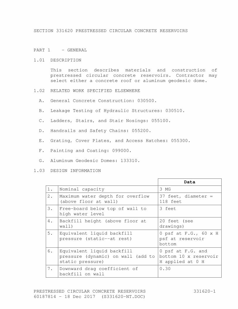
8. Soil bearing capacity (net) 3,000 psf
9. Seismic: Per AWWA D110, including Section 4
Ss = 1.508 S1 = 0.605 Sds = 1.005 Sd1 = 0.605 I = IV
1.04 BID-SUBMITTALS RESPONSIVENESS
The following items shall be included in the bid documents:
A. The Prestressed Concrete Tank shall be constructed by a single Tank Contractor experienced in the construction of circumferentially prestressed cast-in-place concrete tanks utilizing freed neoprene bearing pad connections at the base of the wall, PVC waterstops, seismic cables spanning the wall to footing joint, and a column supported flat slab roof.
B. Written statement that the tank constructor has successfully completed at least three circumferentially strand wrapped prestressed Type 1 concrete tanks 2 MG or larger in the last 10 years. The referenced three tanks shall have Type 1 corewalls. Experience with tank construction having other than what is indicated in the drawings shall not be considered. All tanks listed for the experience requirements must have been built in the tank constructor’s own name or one of its divisions. At least two of the tanks shall have been in successful service for a minimum of five years.
C. The name and address of the tank constructor, if different than the prime bidder or General Contractor.
D. The name of the General Contractor's proposed superintendent who will be in direct charge of the project for the full duration of the contract and the name, of the proposed tank subcontractor's superintendent who will be in direct charge of the reservoir construction.
The proposed tank construction superintendent shall be currently employed by the qualified tank constructor and shall have been the tank construction superintendent on no less than two strand-wrapped prestressed concrete tanks during the last ten years. The tank superintendent shall have been under the direct employment of the tank

PRESTRESSED CIRCULAR CONCRETE RESERVOIRS 331620-3 60187814 - 18 Dec 2017 (S331620-NT.DOC)
constructor for both tanks listed and will be required to be on the project site full-time and in responsible charge during all tank concrete construction activities.
E. The tank constructor may subcontract the tank design and tank prestressing operations to a prestress tank designer and prestressor who meets the experience requirements of this section for performing tank design and prestressing operations.
F. The prestress Tank Designer shall have in its employ a professional design engineer who shall have designed a minimum of 5 AWWA D110 Type I prestressed tanks located within a region with a mapped spectral response acceleration, Ss, of 1.0g or greater.
G. The Tank Contractor or Tank constructor’s listed Tank designer and Prestressor shall have successfully completed prestressing activities, as specified herein, on a minimum of 10 prestressed concrete tanks, greater than or equal to 2 million gallons in size, used for potable water storage in the last 10 years. At least 5 of the above tanks shall have been in successful service for a minimum of five years. Experience gained on work not meeting all of the technical requirements of this specification will not be considered for meeting the necessary experience requirements.
H. Descriptive literature of the strand wrapping, vertical prestressing (and/or metal diaphragm), and shotcrete machinery to be used that meets these specifications. Literature shall include actual printouts or other records of applied wrapping force recordings (as well as force elongation diagrams, if available) taken from projects on which the proposed prestressing equipment and systems have been used.
I. A written statement from the tank prestressor indicating that the prestressor has a minimum of two operable strand-wrapping and automated shotcrete machines meeting these specifications.
1.05 SUBMITTALS AFTER AWARD OF CONTRACT
A. Provide submittals in accordance with the General Provisions and Section 013300.
PRESTRESSED CIRCULAR CONCRETE RESERVOIRS 331620-4 60187814 - 18 Dec 2017 (S331620-NT.DOC)
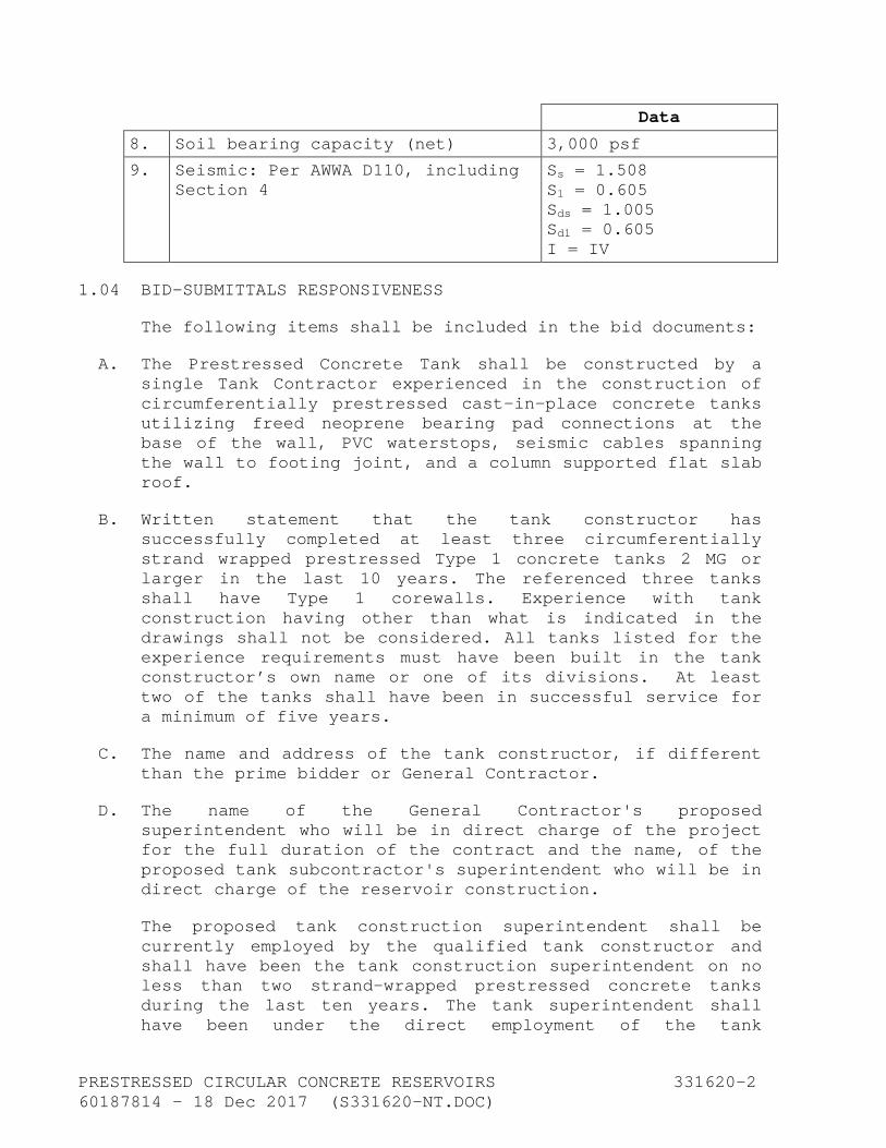
B. Set of reservoir design calculations and drawings indicating the procedures to be used and the ability of the proposed reservoir to resist loads specified. The reservoir design calculations and drawings shall be signed and stamped by a civil or structural engineer registered in the state of California who has at least five years of experience in the design of the type of reservoir specified. Said engineer must be under the full-time employment of the reservoir General Contractor or the subcontractor performing the tendon wrapping and stressing operations. Submit a list of at least three prestressed concrete reservoirs completed in the last five years and stamped and signed by said engineer.
C. Detailed construction drawings prepared by the Contractor shall include:
1. Scaled dimensional drawings.
2. Accessory list with fabrication details.
3. Erection drawings.
4. Catalog cuts and description of standard manufactured items.
5. Location, size, and anchorage of vertical and circumferential prestress reinforcement.
6. Prestress forces including initial, temporary, final, and related losses.
D. Provide documentation relative to concrete reservoir work as may be specified elsewhere in the construction specifications.
E. Concrete that comes in direct contact with potable water shall include the following:
1. Cement and admixtures shall be NSF/ANSE 61 certified.
2. Aggregates shall be tested and approved by one of the following methods:
a. Provide test cylinders using the proposed mix designs for concrete that comes in direct contact with potable water and test as a Barrier Material per Chapter 5of NSF/ANSE 61-

PRESTRESSED CIRCULAR CONCRETE RESERVOIRS 331620-5 60187814 - 18 Dec 2017 (S331620-NT.DOC)
2005. Concrete shall be tested for all CA Title 22 radionuclides listed in Table 64442.
b. Gross alpha radionuclides testing of the dry aggregates using test procedures acceptable to the California Department of Public Health.
3. If NSF/ANSI 61 certified cement and admixtures are not available the following testing procedure shall be required:
a. Provide concrete test cylinders for each mix design that will come in contact direct with potable water to an approved testing laboratory.
b. Concrete specimens shall be soak-tested to verify water quality is in compliance with NSF/ANSI 61-2011 Chapter 5-Barrier Materials. Concrete specimens shall be tested for the items listed in NSF/ANSI 61 Table 3.1-Portland and Hydraulic Cements.
4. Testing shall be conducted by an ANSI or ELAP accredited product certification body for Drinking Water Quality.
F. Mill certificates that prestressing strand comply with these specifications.
G. Stress-strain curves and physical properties of the vertical prestressed reinforcing identified specifically for this project.
H. Submittals for admixtures proposed for use in the concrete reservoir walls.
I. Certificate of compliance with AWWA D110 as modified herein.
J. Submit evidence to the Owner’s Representative, prior to the preparation of shop drawings and installation of vertical tendons, that the proposed tendon anchorage system meets the requirements of these specifications. Should such anchorage systems not meet the specifications, the Owner’s Representative may order anchorage tests to be made. Such testing expenses shall be paid by the Contractor.

PRESTRESSED CIRCULAR CONCRETE RESERVOIRS 331620-6 60187814 - 18 Dec 2017 (S331620-NT.DOC)
1.06 BASIS OF DESIGN
A. The prestressed concrete reservoir shall conform to the dimensions and be equipped with the appurtenances shown in the drawings and shall consist of cast-in-place concrete floor. The cast-in-place concrete core wall shall be post-tensioned vertically with steel rods and circumferentially with wrapped strand and protected with shotcrete and specified coatings.
B. Roof and Roof Supports:
1. Design flat roofs with drop panels in accordance with ACI 318. Roof designs that incorporate post-tensioning, precasting, dome, flat slab without drop panels, or waffle-type structures will not be considered.
2. Concrete roof shall be two-way flat slab poured-in-place reinforced concrete. The roof shall incorporate drop panels and shall be supported by circular spiral-reinforced concrete columns, as indicated in the drawings.
3. The concrete cover over column ties or spiral reinforcing in columns shall be 1.5 inch nominal with a ±1/4-inch construction tolerance.
C. Wall:
1. Walls shall be cast-in-place reinforced concrete. Do not use precast or shotcrete walls.
2. Wall-to-Wall Footing Connection: Support walls by solid neoprene bearing pads allowing free radial movement of the wall relative to the wall footing. Tie the walls circumferentially to the wall footing with seismic cables consisting of hot-dipped galvanized strands encased in closed-cell sponge rubber sleeves permitting a radial free movement of the wall of at least 3/4 inch. Provide a 9-inch by 3/8-inch PVC center bulb water stop connection between wall and wall footing.
3. Wall-to-Roof Connection – Either:
a. Coordinate the aluminum dome roof with the dome roof manufacturer’s anchorage requirements. Provide an elastomeric sealant between wall and roof as indicated in the drawings, or:

PRESTRESSED CIRCULAR CONCRETE RESERVOIRS 331620-7 60187814 - 18 Dec 2017 (S331620-NT.DOC)
b. Support the flat slab roof by solid neoprene bearing pads allowing free radial movement of the wall relative to the roof or vice versa. Provide an elastomeric sealant between wall and roof as indicated in the drawings.
4. Seismic Forces: Calculate forces and moments resulting from water sloshing and seismic accelerations of roof, wall and water loads in accordance with AWWA D110, ASCE 7-05 ACI 350.3.
5. Bearing Pads:
a. Support reservoir walls around the circumference of the reservoir by neoprene bearing pads of the size and thickness indicated in the submitted drawings. Use neoprene sponge-rubber filler pads to seal the reservoir between the bearing pads.
b. The minimum pad thickness under reservoir walls shall be 1 inch or as determined per dome roof requirements, or 1/2 inch under a roof slab.
c. The minimum total neoprene pad width under reservoir walls shall be 3 inches.
d. Loads transmitted through neoprene pad areas shall account for all vertical and horizontal forces.
e. Base neoprene pad sections on continuous loading values not to exceed those allowed in the neoprene design manuals.
f. Fill voids remaining between wall and wall footing and between wall and roof, not filled completely with solid neoprene pads, with closed-cell neoprene sponge-rubber pads and soft mastic to ensure a substantially unrestrained free movement of wall and roof.
6. Minimum final circumferential prestressing force for water load at the bottom of the wall shall be:
Pcw = 62.5 (R) (H) (lbs/ft of height)
in which:

PRESTRESSED CIRCULAR CONCRETE RESERVOIRS 331620-8 60187814 - 18 Dec 2017 (S331620-NT.DOC)
R = inside radius of wall (feet).
H = maximum overload water height (feet).
This force shall taper uniformly to zero at the top of the maximum overflow water height.
7. Minimum final circumferential prestress for differential temperature and dryness bending (Pctd) at any height on the wall, for aboveground wall conditions (per these specifications), shall be 200 psi over the water load and after deduction of all losses. This compression may taper to zero at a distance 6 feet below the minimum backfill height.
8. Minimum Circumferential Backfill Force on Wall (Pcb):
Pcb = (h) (p) (R + 0.0833 t) (lbs/ft of height)
in which:
R = inside radius of wall (feet).
h = height of soil above wall-footing (feet).
p = equivalent liquid backfill pressure (lbs/C.F.) under seismic loading.
t = total wall thickness including cover over prestressing wires (inches).
9. The minimum "final" vertical compression and the vertical prestressing force (Pvtd) for poured-in-place walls, at any point around the reservoir wall, shall be no less than the amounts (Pctd) calculated herein. The total vertical post-tensioning (200 psi x Ag at wall) shall be applied prior to the circumferential prestressing.
10. Maximum final stress in circular and vertical prestress steel (fse) shall not be less than the maximum allowable initial stress of 0.75 minimum ultimate strength (±1.5% MUS) less 25,000-psi stress losses.
11. Minimum initial-to-final stress ratio (I.F. ratio) is the value of the not-to-be-exceeded initial steel stress divided by the value of the final steel stress as defined herein.
PRESTRESSED CIRCULAR CONCRETE RESERVOIRS 331620-9 60187814 - 18 Dec 2017 (S331620-NT.DOC)
D. Maximum Compressive Stress in Concrete Walls: The maximum compressive stress in concrete walls, under any combination of load conditions, at any stage during the construction, and without any allowance for stress losses due to creep of steel and concrete or due to elastic deformation or concrete shall not exceed 0.55 f'c.
1. Minimum Total Overall Wall Thickness: The minimum overall wall thickness shall be no less than the value calculated below:
toverall = [(I.F. Ratio) x (Pcw + Pctd)] + Pcb
(0.55 f'c) x (12)
2. Bottom edge restraint reinforcing for cast-in-place walls prestressed vertically with threadbar tendons shall be reinforced on the inside bottom of the reservoir wall with No. 5 bars, having a length not less than 40% of the wall height and spaced 18 inches maximum on centers.
E. Wall Footing:
1. The circumferential wall footing reinforcing shall have a minimum total cross-sectional area no less than 0.5% of the wall footing section excluding any reinforcement requirements for tension forces due to water loads.
2. Tension forces caused by liquids acting on wall footings shall be taken fully by reinforcing steel in the radial and circumferential direction at steel stresses not exceeding 18,000 psi. No value shall be given to radial friction resistance effects of soils on footings.
3. Hinged or fixed wall-to-wall footing connections shall not be considered.
4. Radial and circumferential bar sizes shall not exceed 3/4 inch in diameter.
5. Stagger splices in parallel bars to avoid more than one splice at any point around the circumference of the wall footing.
6. Install water stops (6 inches by 3/8 inch)in radial construction joints in the floor and wall footings and connect and seal to the circumferential water stop
PRESTRESSED CIRCULAR CONCRETE RESERVOIRS 331620-10 60187814 - 18 Dec 2017 (S331620-NT.DOC)
connecting the wall-to-wall footing. The wall footing may be poured monolithically with the floor. Circumferential joint water stop between the floor slab and ringwall footing shall be continuous and connected to radial water stop when the footing is cast over the floor slab or circumferentially adjacent.
7. The minimum width of the wall footing shall be 4 feet. The minimum thickness shall be 18 inches.
F. Floor:
1. The floor shall be no less than 6-1/2 inches thick.
2. The cross-sectional area of steel provided for floor reinforcing in each direction shall be no less than 0.5% of the nominal floor cross-sectional area with a maximum bar spacing of 12 inches. Floor thicknesses in excess of 8 inches shall have two mats of reinforcing with the bottom mat being at least 3 inches clear to subgrade.
3. Do not post-tension floor slab.
G. Column Footings:
1. Column footings shall be cast with or project above the floor slab. The minimum size of column footings shall be 4 feet by 4 feet.
2. Footing reinforcing steel added to the floor reinforcement shall be evenly spaced and staggered to the normal slab reinforcing.
H. Prestressing System:
1. No stressing system will be considered unless it has been successfully used on reservoirs of similar size and capacity.
2. Vertical wall prestressing tendons shall be 1.25-inch or 1.375-inch-diameter thread bars, with screw nut anchors.
3. Circumferential prestressing of reservoir walls shall be done with hot-dipped galvanized strand.
4. Circumferential wrapping forces applied on strand shall be continuously electronically monitored and
PRESTRESSED CIRCULAR CONCRETE RESERVOIRS 331620-11 60187814 - 18 Dec 2017 (S331620-NT.DOC)
permanently recorded while the steel is being wrapped. Die-drawing of prestress reinforcement will not be permitted.
5. Vertical tendon forces and elongations shall be electronically monitored and permanently recorded from beginning to end of each stressing operation.
6. Do not base reservoir wall design on wrapping tolerances greater than what the wrapping machinery can continuously meet based upon electronically recorded data taken from previous projects.
7. Do not space wrapped strands in any vertical layer closer than 2.5 strand diameters or less than 3/8-inch clearance between individual strands, whichever offers the greatest clearance between strands.
8. Cover each interior strand layer with shotcrete of 0.375-inch thickness.
9. The minimum cover over the final strand layer shall be 1.5 inches.
10. The horizontal distance between vertical prestressing tendons shall not exceed 50 inches.
11. Do not consider circumferential reservoir wall systems based on cable- or rod-type tendons involving the circumferential movement of prestressing steel relative to the wall surface. Do not consider systems utilizing strand cables placed inside ducts that are incorporated circumferentially in the core wall or placed manually around the exterior of the core wall.
I. Anchorage for Vertical Posttensioned Tendons:
1. Secure posttensioned prestressing at the ends by means of permanent anchoring devices that shall hold the prestressing steel at a force not less than 95% of the guaranteed minimum tensile strength of the prestressing steel.
2. Distribute load from the anchoring devices to the concrete through steel bearing plates.
3. Use fully threaded anchor connections at each end of the vertical prestressing tendon which incorporates a
PRESTRESSED CIRCULAR CONCRETE RESERVOIRS 331620-12 60187814 - 18 Dec 2017 (S331620-NT.DOC)
spherical-shaped bearing surface which matches the conical bearing surface in the bearing plate.
4. The contact point of the spherical-shaped vertical prestressing bearing surface to conical hole shall be approximately 1/4 inch to 1/2 inch below the bearing plate surface.
5. Do not use wedge anchors for permanent tendon anchor hardware.
J. Anchor Pockets for Vertical Tendons:
1. Form anchor pockets for vertical prestressing tendons with permanently emplaced hot-dipped galvanized cylinders welded securely to the top bearing plate.
2. Seal anchor pockets from moisture and concrete intrusion during concrete activities with wooden plugs and plastic tape.
3. Anchor pockets for vertical prestressing tendons must have provisions to allow flushing of ducts with water during concrete placement.
PART 2 - MATERIALS
2.01 CONCRETE ADMIXTURES
A. Do not use admixtures containing chlorides, fluorides, sulfides, or nitrates in any concrete mix for prestressed concrete reservoirs.
B. Do not use air-entraining admixtures in concrete mix Class PA.
2.02 CONCRETE MIX DESIGN
A. Conform to Section 030500 except as modified herein.
B. The maximum water-cement ratio for Classes PA and PB concrete shall be 0.42 by weight.
C. Use classes of concrete as described in the following table:

PRESTRESSED CIRCULAR CONCRETE RESERVOIRS 331620-13 60187814 - 18 Dec 2017 (S331620-NT.DOC)
Class
Type of Work
Minimum 28-Day Compressive Strength (in psi)
Minimum Cement Content
(lbs/C.Y.)
PA Prestressed reservoir walls
5,000 564
PB Prestressed reservoir roof slab and columns
4,000 564
PS Shotcrete 5,000 1c:3s
A All other concrete
4,000 Section 030500
D. Slump shall be as follows:
1. Prestressed Reservoir Walls, Roof Slab and Columns: 6 inches maximum.
2. Shotcrete: 5 to 8 inches.
3. Other Concrete: See Section 030500.
2.03 SHOTCRETE
A. Shotcrete shall be composed of portland cement, sand, and water applied as a "wet mix" to the reservoir walls.
B. Cement shall be in accordance with Section 030500.
C. Do not use admixtures containing chlorides, fluorides, sulfides, or nitrates.
D. Coarse sand shall conform to the following requirements:
Sieve Size
Percent Passing By Weight
3/8 inch 100
No. 4 95 to 100
No. 8 80 to 90
No. 16 50 to 85
No. 30 25 to 60
No. 50 10 to 30
No. 100 2 to 10
PRESTRESSED CIRCULAR CONCRETE RESERVOIRS 331620-14 60187814 - 18 Dec 2017 (S331620-NT.DOC)
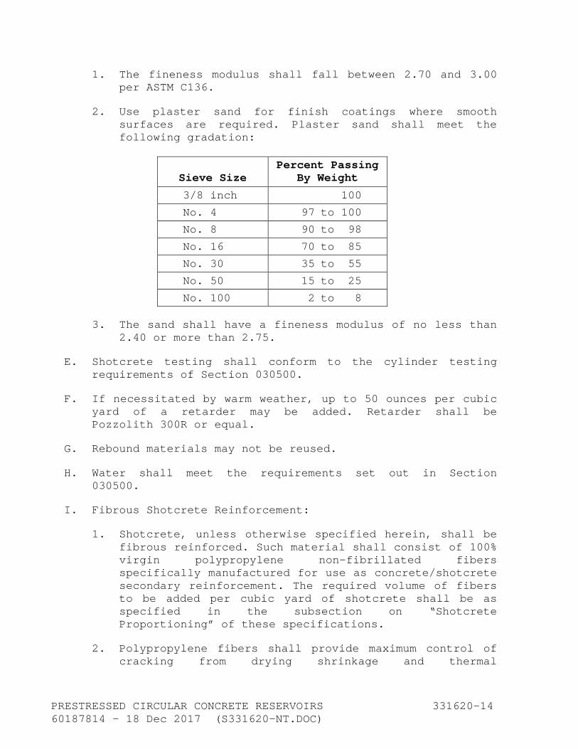
1. The fineness modulus shall fall between 2.70 and 3.00 per ASTM C136.
2. Use plaster sand for finish coatings where smooth surfaces are required. Plaster sand shall meet the following gradation:
Sieve Size Percent Passing
By Weight
3/8 inch 100
No. 4 97 to 100
No. 8 90 to 98
No. 16 70 to 85
No. 30 35 to 55
No. 50 15 to 25
No. 100 2 to 8
3. The sand shall have a fineness modulus of no less than 2.40 or more than 2.75.
E. Shotcrete testing shall conform to the cylinder testing requirements of Section 030500.
F. If necessitated by warm weather, up to 50 ounces per cubic yard of a retarder may be added. Retarder shall be Pozzolith 300R or equal.
G. Rebound materials may not be reused.
H. Water shall meet the requirements set out in Section 030500.
I. Fibrous Shotcrete Reinforcement:
1. Shotcrete, unless otherwise specified herein, shall be fibrous reinforced. Such material shall consist of 100% virgin polypropylene non-fibrillated fibers specifically manufactured for use as concrete/shotcrete secondary reinforcement. The required volume of fibers to be added per cubic yard of shotcrete shall be as specified in the subsection on “Shotcrete Proportioning” of these specifications.
2. Polypropylene fibers shall provide maximum control of cracking from drying shrinkage and thermal
PRESTRESSED CIRCULAR CONCRETE RESERVOIRS 331620-15 60187814 - 18 Dec 2017 (S331620-NT.DOC)
expansion/contraction and added toughness of the shotcrete.
3. The fibers shall be manufactured in accordance with applicable building codes and ASTM C1116, Type III 4.1.3 and ASTM C1116 (Ref. ASTM C1018) Performance Level I5 outlined in Section 21, Note 17. Fibrous concrete reinforcement shall be as manufactured by the Fibermesh Company, Chattanooga, Tennessee, or equal.
4. Acceptable polypropylene fibers shall have the following physical characteristics:
a. Specific Gravity: 0.91.
b. Tensile Strength: 80 to 110 ksi.
c. Fiber Length: Graded per manufacturer.
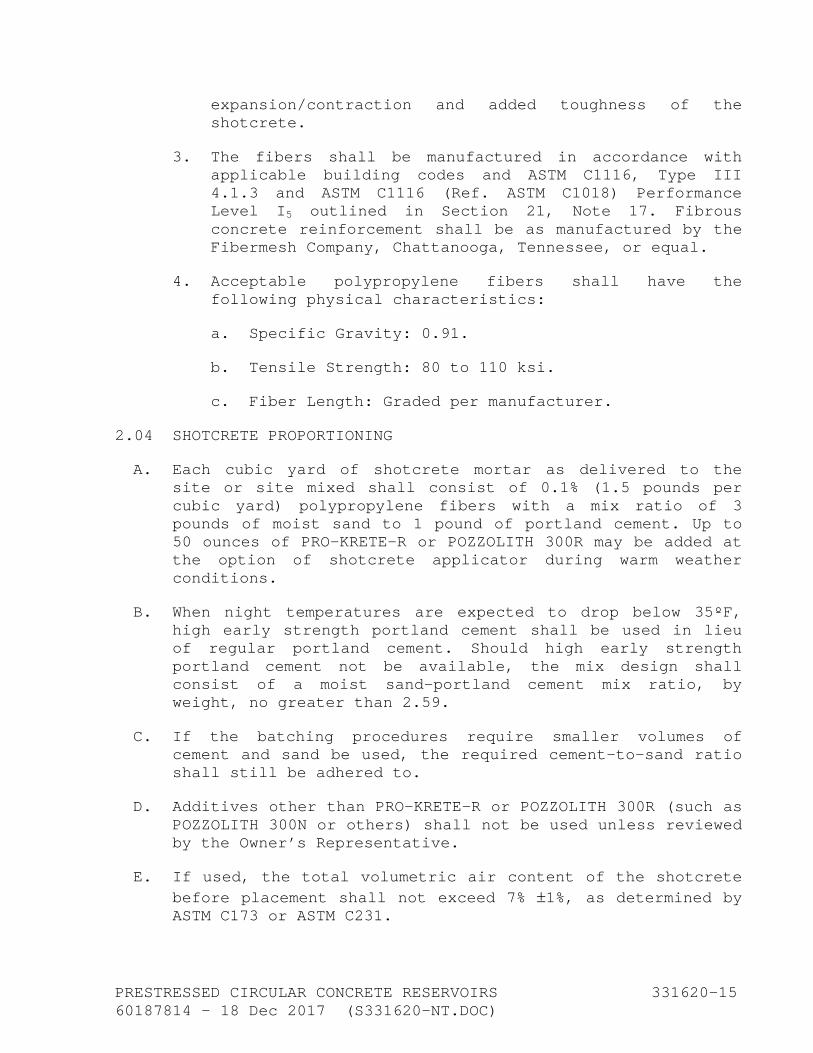
2.04 SHOTCRETE PROPORTIONING
A. Each cubic yard of shotcrete mortar as delivered to the site or site mixed shall consist of 0.1% (1.5 pounds per cubic yard) polypropylene fibers with a mix ratio of 3 pounds of moist sand to 1 pound of portland cement. Up to 50 ounces of PRO-KRETE-R or POZZOLITH 300R may be added at the option of shotcrete applicator during warm weather conditions.
B. When night temperatures are expected to drop below 35ºF, high early strength portland cement shall be used in lieu of regular portland cement. Should high early strength portland cement not be available, the mix design shall consist of a moist sand-portland cement mix ratio, by weight, no greater than 2.59.
C. If the batching procedures require smaller volumes of cement and sand be used, the required cement-to-sand ratio shall still be adhered to.
D. Additives other than PRO-KRETE-R or POZZOLITH 300R (such as POZZOLITH 300N or others) shall not be used unless reviewed by the Owner’s Representative.
E. If used, the total volumetric air content of the shotcrete before placement shall not exceed 7% ±1%, as determined by ASTM C173 or ASTM C231.

PRESTRESSED CIRCULAR CONCRETE RESERVOIRS 331620-16 60187814 - 18 Dec 2017 (S331620-NT.DOC)
F. Unless otherwise shown in the drawings, shotcrete cylinder strengths at 28 days shall be no less than specified. Higher shotcrete cylinder strengths shall not permit a reduction in the specified cement content. The cement content in the mix designs may be increased should the specified 28-day strength requirement not be met.
G. The polypropylene fibers and admixtures shall be added to the shotcrete at the time it is batched and in the amounts specified. Additives shall be mixed in strict conformance to the manufacturer’s instructions and recommendations for uniform and complete distribution. Each certificate of delivery supplied by the shotcrete supplier shall indicate the additive trade name, manufacturer’s name, and amount per cubic yard added to each batch of shotcrete.
2.05 PRESTRESSING STRANDS AND SEISMIC CABLES
A. Galvanized seven-wire prestressing strands and seismic cables shall conform with ASTM A416 except as modified:
Nominal strand diameter 3/8 inch
Nominal area after galvanizing 0.089 square inch
Nominal weight/1,000 L.F. 303 pounds
Ultimate tensile strength 21,400 pounds (min)
Yield strength at 1% extension 16,000 pounds (min)
Elongation in 24 inches at fracture
4.5% (min)
Weight of zinc coating 0.85 ounce/square foot (min)
Pitch 12- to 16-strand diameter
B. Store and protect strands from water, rain, moisture, and foreign material prior to use.
2.06 VERTICAL PRESTRESSING BARS
A. Use high-strength threadbars with deformations and screw threads over the entire length of the bars, suitable for mechanical coupling and attachment to anchor assemblies, and anchor nuts with circular ball-shaped face. Anchor nut shall provide a vent for grouting.
PRESTRESSED CIRCULAR CONCRETE RESERVOIRS 331620-17 60187814 - 18 Dec 2017 (S331620-NT.DOC)
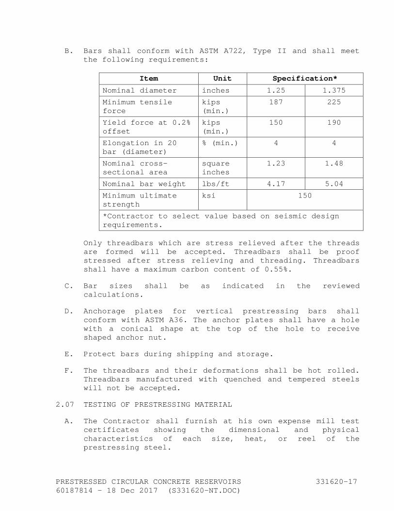
B. Bars shall conform with ASTM A722, Type II and shall meet the following requirements:
Item Unit Specification*
Nominal diameter inches 1.25 1.375
Minimum tensile force
kips (min.)
187 225
Yield force at 0.2% offset
kips (min.)
150 190
Elongation in 20 bar (diameter)
% (min.) 4 4
Nominal cross-sectional area
square inches
1.23 1.48
Nominal bar weight lbs/ft 4.17 5.04
Minimum ultimate strength
ksi 150
*Contractor to select value based on seismic design requirements.
Only threadbars which are stress relieved after the threads are formed will be accepted. Threadbars shall be proof stressed after stress relieving and threading. Threadbars shall have a maximum carbon content of 0.55%.
C. Bar sizes shall be as indicated in the reviewed calculations.
D. Anchorage plates for vertical prestressing bars shall conform with ASTM A36. The anchor plates shall have a hole with a conical shape at the top of the hole to receive shaped anchor nut.
E. Protect bars during shipping and storage.
F. The threadbars and their deformations shall be hot rolled. Threadbars manufactured with quenched and tempered steels will not be accepted.
2.07 TESTING OF PRESTRESSING MATERIAL
A. The Contractor shall furnish at his own expense mill test certificates showing the dimensional and physical characteristics of each size, heat, or reel of the prestressing steel.

PRESTRESSED CIRCULAR CONCRETE RESERVOIRS 331620-18 60187814 - 18 Dec 2017 (S331620-NT.DOC)
B. Contractor shall furnish evidence to the Owner’s Representative, prior to the preparation of shop drawings and installation of vertical tendons, that the proposed tendon anchorage system meets the requirements of these specifications. Should such anchor systems not meet the specifications, the Owner’s Representative may order anchorage tests to be made. Such testing expenses shall be paid for by Contractor.
C. Prior to stressing operations, the prestressor shall calibrate recording equipment at an approved testing laboratory to the satisfaction of the Engineer.
D. Continuous force readings for either the vertical or the circumferential prestressing operations shall be developed with electronic or the substantial equivalent strain gauge method force sensing transducers which have a maximum nonlinearity error of ±0.5% and a maximum hysteresis error of ±0.25%.
2.08 CIRCUMFERENTIAL PRESTRESSING EQUIPMENT
A. The circumferential stressing system used shall produce a continuously, electronically (or substantially equivalent) monitored permanent stress or force record along the full length of the strand as it is being applied. The stress variation in any strand at any point around the circumference shall not be greater than ±1.5% of the ultimate strength of the steel. In addition to this record, a system which deflects the tensioned prestressing material between the tensioning device and the wall, after it has left the tensioning device, shall provide a similar continuously monitored stress or force record along its full length as it is being applied to the wall. The recordings shall show that either before or after deflection, the stress variation in the prestressing material at any point around the circumference shall not be greater than ±1.5% of the ultimate strength of the steel.
B. No manually recorded readings will be accepted.
2.09 WATER STOPS
A. Floor Construction Joints: Minimum 3/8-inch by 6-inch water stop with center bulb.
B. Wall-to-Wall Footing Connections: Minimum 3/8-inch by 9-inch water stop with a 3/4-inch-minimum center bulb.
PRESTRESSED CIRCULAR CONCRETE RESERVOIRS 331620-19 60187814 - 18 Dec 2017 (S331620-NT.DOC)
C. Vertical Wall Joints: Minimum 3/8-inch by 6-inch water stop without a center bulb.
D. Water stops shall meet the requirements specified in Section 030500.
2.10 NEOPRENE BEARING PADS
A. Design neoprene bearing pads considering bearing stress, radial wall movement, and shear deflection.
B. Material for the pads shall conform to ASTM D2000 M2BC414A14C12F17 for 40 durometer neoprene pads, ASTM D2000 M2BC310A14C12F17 for 30 durometer neoprene pads, and M2BC517A14C12F17 for 50 durometer neoprene pads.
2.11 CLOSED-CELL NEOPRENE FILLER PADS
Filler pads shall be soft grade conforming to 2A3 of ASTM D1056.
2.12 SEISMIC CABLE SLEEVES
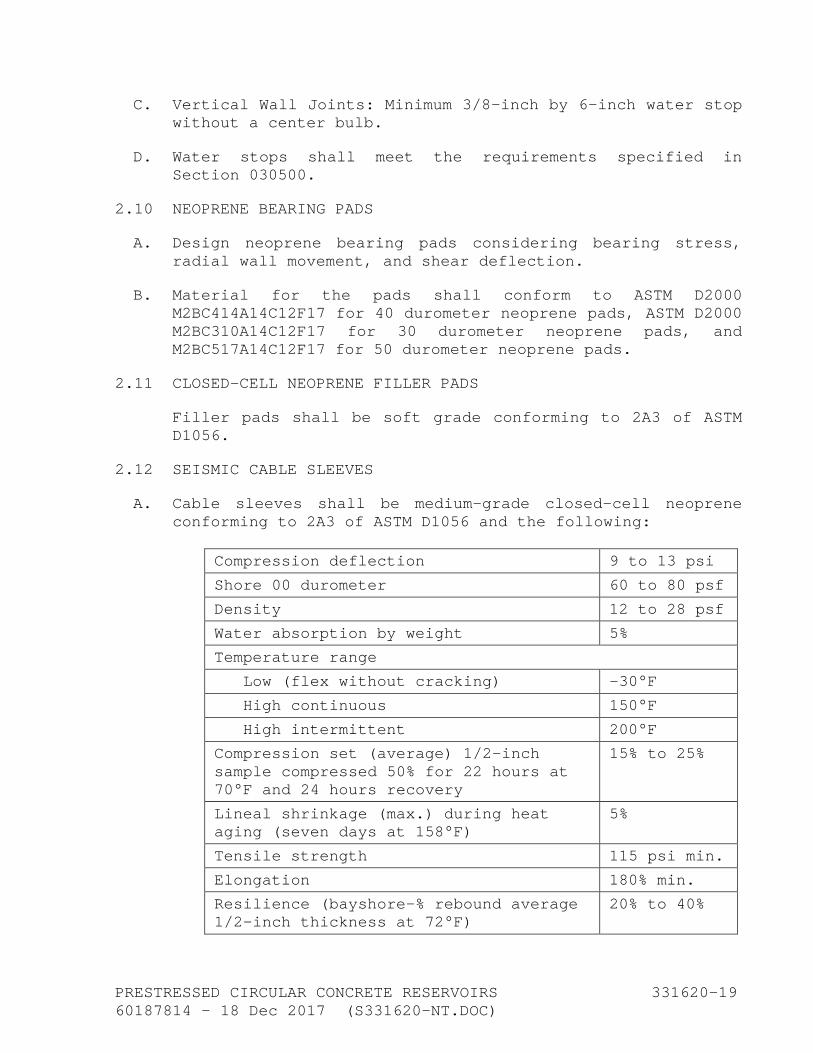
A. Cable sleeves shall be medium-grade closed-cell neoprene conforming to 2A3 of ASTM D1056 and the following:
Compression deflection 9 to 13 psi
Shore 00 durometer 60 to 80 psf
Density 12 to 28 psf
Water absorption by weight 5%
Temperature range
Low (flex without cracking) -30°F
High continuous 150°F
High intermittent 200°F
Compression set (average) 1/2-inch sample compressed 50% for 22 hours at 70°F and 24 hours recovery
15% to 25%
Lineal shrinkage (max.) during heat aging (seven days at 158°F)
5%
Tensile strength 115 psi min.
Elongation 180% min.
Resilience (bayshore-% rebound average 1/2-inch thickness at 72°F)
20% to 40%
PRESTRESSED CIRCULAR CONCRETE RESERVOIRS 331620-20 60187814 - 18 Dec 2017 (S331620-NT.DOC)
B. Material shall be Rubatex R431N or R423N or equal.
2.13 DUCTS FOR VERTICAL TENDONS
A. Duct enclosures for vertical prestressing steel shall be standard 1.25- or 1.375-inch-diameter PVC pipe, Class 160, for 1-1/4-inch-diameter tendons, and 1-1/2-inch-diameter PVC pipe, Class 200 for 1-3/8-inch-diameter tendons, unless otherwise specified in the drawings.
B. Provide ducts with expandable valves to facilitate the injection of epoxy after prestressing.
2.14 EPOXY GROUT FOR VERTICAL TENDONS
A. Epoxy grout shall be a two-part epoxy system that will completely encase and protect the prestressing steel inside ducting and anchors.
B. Do not use portland cement grout.
2.15 ACCESSORIES
A. Pipe Connections:
1. Install and encase piping as indicated in the drawings.
2. Locate piping connections as shown in drawings.
B. Overflow: Circular weir inlet and overflow pipe dimensions as shown in drawings.
C. Ladders: See Section 055100.
D. Roof Hatches: See Section 133310.
E. Roof Vent: The roof vent shall be as shown in drawings with removable stainless steel insect screen.
2.16 HANDRAIL
See Section 055200.
2.17 PAINT AND COATINGS
A. Coat exterior walls below grade using Select Shield 300A, Carboline Bitumastic, Select Products Company, or equal.
PRESTRESSED CIRCULAR CONCRETE RESERVOIRS 331620-21 60187814 - 18 Dec 2017 (S331620-NT.DOC)
B. Coat exposed roof areas with Type II asphalt meeting the requirements of ASTM D449, Type II and clean 3/8-inch pea gravel.
PART 3 - EXECUTION
3.01 PRODUCT DELIVERY, STORAGE, AND HANDLING
A. Package prestressing steel against intrusion of chemical, dirt, moisture, or other contaminants from the atmosphere and for the protection of the steel against physical damage and corrosion during shipping and storage.
B. Prestressing steel that has sustained physical damage through rust or otherwise will be rejected.
C. Store materials and prestressing material delivered to the jobsite off the ground and wrap with polyethylene or sisal-kraft paper to prevent any moisture from coming in contact with the materials.
D. Neatly stack reels of strand, prestressing tendons, anchorages, etc.
3.02 CONCRETE FORMWORK
A. Do not form beveled edges (chamfer) at the vertical joints in the exterior wall of the reservoir.
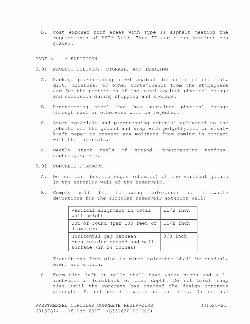
B. Comply with the following tolerances or allowable deviations for the circular reservoir exterior wall:
Vertical alignment in total wall height
±1/2 inch
Out-of-round (per 100 feet of diameter)
±1/2 inch
Horizontal gap between prestressing strand and wall surface (in 24 inches)
3/8 inch
Transitions from plus to minus tolerance shall be gradual, even, and smooth.
C. Form ties left in walls shall have water stops and a 1-inch-minimum breakback or cone depth. Do not break snap ties until the concrete has reached the design concrete strength. Do not use tie wires as form ties. Do not use
PRESTRESSED CIRCULAR CONCRETE RESERVOIRS 331620-22 60187814 - 18 Dec 2017 (S331620-NT.DOC)
snap ties that are designed so that the ends must be broken off before the forms can be removed. Fully threaded stub bolts may be used in lieu of smooth ties with water stops. Taper ties with plastic or rubber plugs of a proven design may be used.
D. Fill taper form tie holes that extend through the reservoir wall as follows:
1. Locate large end of taper tie on the "wet" side of the wall.
2. Sandblast or roughen tie rod hole and blow clean prior to filling.
3. After sandblasting and cleaning, drive rubber plug with one end open to the center of the hole. Plug size shall be larger in diameter than the diameter of the hole at the center of the wall.
4. Coat entire annular surface of the hole with epoxy prior to dry-packing of the holes. Apply epoxy in accordance with manufacturer's instructions.
5. Dry-pack each side of hole with cement mortar consisting of one part cement well mixed with one part sand by volume and only sufficient water such that mortar will ball together when molded by slight pressure of the hands. Apply dry pack to the "wet" side of the wall first prior to dry-packing dry side. Pack into the hole with tool.
6. Cure dry-pack surfaces. Coat the "wet" side of the dry pack with epoxy coating.
E. The wall form design shall allow wall sections to be poured full height without creating horizontal cold joints. Form ties shall be of sufficient strength and number to prevent spreading of the forms during the placement of concrete and shall permit ready removal of the forms without spalling or damaging the concrete.
F. Concrete placement in walls shall be done only through pour openings in the wall forms and may not be poured from the top through the use of "elephant trunks" or tremies. Either erect the complete form on one side of the wall and erect the form on the other side of the wall while the concrete placement is in progress, or remove pour panels from either

PRESTRESSED CIRCULAR CONCRETE RESERVOIRS 331620-23 60187814 - 18 Dec 2017 (S331620-NT.DOC)
the inside or outside form assembly before concrete placement starts. The vertical distance between horizontal rows of openings shall not exceed 8 feet with the lowest row of openings being no higher than 2 feet from the bottom of the wall. The minimum pouring opening size shall be 24 inches by 18 inches.
G. Forms may be removed as soon as the concrete has developed sufficient strength to prevent sagging, misalignment, spalling, cracking, or breaking of edges of the concrete. Do not remove wall forms prior to 12 hours after completion of the wall concrete placement.
3.03 CONCRETE JOINTS AND WATER STOPS
A. Concrete joints shall conform to Section 030500 and as specified herein.
B. Splice water stops at intersections between wall, wall footing, roof slab, and floor slab water stops.
C. Bend up horizontal water stops during placing of concrete until the concrete has been brought to the level of the water stop. Then place additional concrete over the water stop and vibrate the concrete.
D. Prior to installation of water stop, provide water stop regular splice and intersection splice samples with each type and size of water stop. Make splices in the presence of the Owner's Representative. Make splice samples by the workers designated to make field splices.
3.04 CONCRETE FINISHES
A. Finishes shall conform to Section 030500 except as modified herein.
B. Roof slab shall receive a steel trowel and light hair broom finish.
3.05 CONCRETE CURING
A. Cure concrete in accordance with the methods specified herein for the different parts of the work and described in detail in the following paragraphs. These methods are considered to be minimum for curing. The conditions that exist in the field during placement and curing may require additional curing procedures and efforts to ensure proper
PRESTRESSED CIRCULAR CONCRETE RESERVOIRS 331620-24 60187814 - 18 Dec 2017 (S331620-NT.DOC)
protection and curing of the concrete. Select and implement the appropriate method commensurate with climatic conditions.
B. Cure floor slab using Method 3 or 4 as specified below.
C. Cure exterior walls using Method 2 or 4 as specified below.
D. Cure roof slab using Method 3 or 4 a specified below.
E. Cure concrete for not less than 14 days after placing in accordance with the following methods:
1. Method 1, Water Spray Method: Tightly close off concrete surfaces to be cured by bulkheads or other means or entirely surround by tight enclosures, and keep the concrete surfaces moist by sprinkling, spraying, or other means.
2. Method 2, Wet-Burlap-Mat Method: Thoroughly wet and cover concrete surfaces to be cured with wet burlap mats as soon as the forms have been stripped or as soon as the concrete has set sufficiently to avoid marring the surface. Keep entire concrete surface and burlap continuously and completely wet during the entire curing period.
3. Method 3, Curing Blanket Method:
a. Thoroughly wet concrete surfaces to be cured and cover with curing blankets as soon as the concrete has set sufficiently to avoid marring the surface. The curing blankets shall be weighted to maintain close contact with the concrete surface during entire curing period. Should the curing blankets become torn or otherwise ineffective, keep surfaces moist and replace damaged sections. The curing blankets shall consist of one of the following two types:
(a) Sheets of heavy waterproof sisal-kraft paper laid with the edges butted together and with the joints between strips sealed with 2-inch-wide strips of sealing tape or with the edges lapped not less than 3 inches and fastened together with waterproof cement to form continuous watertight joints; or
PRESTRESSED CIRCULAR CONCRETE RESERVOIRS 331620-25 60187814 - 18 Dec 2017 (S331620-NT.DOC)
(b) Sheets of clean polyethylene, having a minimum thickness of 4 mils, laid with edges butted together and with the joints between sheets sealed with 1-inch-wide strips of acetate tape.
b. During the curing period, do not permit traffic of any nature or depositing of objects, temporary or otherwise, on the curing blankets.
4. Method 4, Curing Compound Method:
a. Spray the surface with two coats of liquid curing compound. Apply in accordance with the manufacturer's instructions to cover the surface with a uniform film that will seal thoroughly. Apply second coat at 90 degrees to the first coat.
b. Apply curing compound immediately after completion of the finish on unformed surfaces and within two hours after removal of forms on formed surfaces. Repair formed surfaces within the said two-hour period; provided, however, that any such repairs which cannot be made within the said two-hour period shall be delayed until after Method 1, 2, or 3 has been applied. When repairs are to be made to an area on which curing compound has been applied, first sandblast the area to remove the curing compound, then repair.
c. Wherever curing compound may have been applied to surfaces against which concrete subsequently is to be placed and to which it is to adhere, remove the curing compound entirely by sandblasting prior to the placing of new concrete.
d. Where the curing compound method is used, exercise care to avoid damage to the seal during the curing period. Should the seal be damaged or broken before the expiration of the curing period, repair the damaged portions immediately by the application of additional curing compound.
3.06 SHOTCRETE PLACING, CURING, AND FINISHING
A. Surface Preparation: Exterior surfaces of the concrete core wall and dome ring (if any), which will receive strand wrapping, shall be abrasive blasted, regardless of the
PRESTRESSED CIRCULAR CONCRETE RESERVOIRS 331620-26 60187814 - 18 Dec 2017 (S331620-NT.DOC)
forming method used, by a mechanical etching or shotblast system combined with a vacuum recovery system, or a self-contained waterblasting system. Systems that have not been used successfully in the past to prepare circular reservoir wall surfaces for shotcreting and strand wrapping or systems that rely on sandblasting or steel shot without a vacuum system will not be allowed. The surface shall be abrasive blasted sufficiently to remove laitance, form oil, or other types of coatings. The surface shall be cut to a minimum CSP5 profile, as established by the International Concrete Repair Institute (ICRI), over a minimum of 90% of the surface being prepared as measured over any 1-foot-square area. The prestressing subcontractor who is performing the abrasive blasting shall make available to the inspector ICRI sample coupons to assist in evaluating the abrasive cut.
B. Placing:
1. Apply shotcrete using the wet mix process. Nozzles shall be mounted on power-driven machinery maintaining the nozzle parallel with and at right angle to the surface being sprayed. No manual application of shotcreting will be accepted except for repair work or architectural treatment. Start shotcreting at the bottom of the wall and progress around the reservoir wall before moving up the wall. Do not build up the shotcrete in front of the strands or reinforcing when applying shotcrete behind strands or reinforcing. The minimum shotcrete cover over the outermost wrapped strand shall be 1.5 inches.
2. Each layer of shotcrete shall have sufficiently set to eliminate sagging during application of the next layer.
3. Do not apply shotcrete if the wind velocity exceeds 5 mph or air temperature is less than 55°F.
4. Remove and replace shotcrete that is damaged by rain, wind, or frost.
5. Apply shotcreting in layers of approximately 3/8 inch to 1/2 inch in thickness until the total thickness has been obtained. Protect adjacent buildings, concrete surfaces, equipment, and vehicles during shotcrete application. Repair damage resulting from shotcreting operations.
PRESTRESSED CIRCULAR CONCRETE RESERVOIRS 331620-27 60187814 - 18 Dec 2017 (S331620-NT.DOC)
6. The air capacity of the compressor shall be large enough that the minimum amount of air to be available at the nozzle shall be no less than 400 cfm, whether or not air from the same air supply is used for other purposes.
7. Deliver shotcrete materials to the jobsite in ready-mix trucks from batching plants. Job mixing will be accepted provided automatic weigh batch plants are used.
8. Shotcrete Covercoats Over Wrapped Strand:
a. Cover each layer of wrapped prestressing steel with shotcrete until a minimum cover of 3/8 inch over the steel has been obtained.
b. Apply the final covercoat in at least three layers of equal thickness to make up for the full thickness of shotcrete over the final strand layer.
c. Complete each layer of shotcrete for the full circumference of the reservoir and substantially the full height of that layer before applying the next layer of shotcrete.
C. Finishing: The finished wall surface shall be a vertical plane with no undulations. Shotcrete transition from multilayer strand wrap to single-layer strand wrap near the bottom of the wall shall be gradual. Finish shall be natural gun finish.
D. Curing:
1. Intermediate shotcrete layers that will not receive subsequent layers of shotcrete for 12 hours or more shall be kept damp until application of the subsequent layers.
2. Completed shotcrete surfaces that do not receive additional coatings shall be water cured for a period of at least seven days by encapsulating the entire shotcrete surface with plastic sheeting. Lap and seal the plastic sheeting to properly cure the shotcrete. Do not use membrane curing methods utilizing curing compounds or wax-based residuals.

PRESTRESSED CIRCULAR CONCRETE RESERVOIRS 331620-28 60187814 - 18 Dec 2017 (S331620-NT.DOC)
3.07 CIRCUMFERENTIAL PRESTRESSING
A. Stressing System: Prestress walls circumferentially by prestressing strand that is wound onto the wall at the uniform strand load required. Provide the stressing system with means to continuously, instantaneously monitor and record the force in the strand at any location around the wall and maintain the force in the strand within a tolerance of ±1-1/2% of the ultimate strength of the prestressing. No manually recorded force readings will be accepted. No die-drawing of prestressing reinforcement is permitted. Upon completion of the stressing operation, all recordings shall become the property of the Owner.
B. In the event that gaps between the core wall and the wrapped prestressing material develop that exceed 3/8 inch, discontinue wrapping and build up the wall with shotcrete to provide the proper curvature. Alternatively, if approved by the Owner’s Representative, the gaps may be dry-packed after wrapping is completed and before shotcreting is started.
C. Wrapping over intermediate shotcrete coats or built-up shotcrete areas may commence 12 hours after the shotcrete has been applied. The compressive stress applied to the mortar shall not exceed 80% of the compressive strength of the mortar at the time of wrapping.
D. Do not allow prestressing material exposed to excessive temperatures to increase by more than 50 degrees at any time during such application due to detrimental stress buildup or damage.
E. Application:
1. Do not start circumferential stressing until the concrete has reached a compressive strength of 3,000 psi. Under no condition shall concrete compressive stress exceed 55% of the concrete strength at the time of stressing. Wrapping over flash coats may commence 12 hours after the shotcrete has been applied providing that the shotcrete has reached a strength of 250 psi.
2. Anchor prestressing strand to the wall at least once for every reel to minimize the loss of strand in case of a strand break. Do not anchor one strand to a previously wrapped strand either temporarily or permanently. Join prestressed strands by splices that

PRESTRESSED CIRCULAR CONCRETE RESERVOIRS 331620-29 60187814 - 18 Dec 2017 (S331620-NT.DOC)
will develop 95% of the guaranteed ultimate strength of the strand. Splice material shall be the same alloy as the prestressing strand.
3. The average vertical spacing between any two strands wrapped circumferentially and to be encased in shotcrete shall have a minimum clearance of 1-1/2-strand diameters or 3/8 inch, whichever is larger. Strands not meeting the spacing requirements shall be spread or otherwise removed.
4. Do not bundle or drape strand around pipe or manhole openings. Spread any strands falling in such areas over a predetermined area above and below such wall openings in conformance with the above strand spacing requirements.
5. Place strands wrapped near openings no closer than 2 inches from the exterior opening surface.
6. If the strand-wrapping load is different from the specified design load, discontinue stressing operations until adjustments are made to the stressing system.
7. Do not use prestressing strand and anchors as a ground for welding operations.
F. Final Force:
1. The initial electronically (or substantial equivalent) recorded steel stress shall not exceed 75% or less than 72% of the guaranteed minimum ultimate strength (M.U.S.) of the steel at any time during and after stressing.
2. An automatic, continuously electronically (or substantial equivalent) monitored permanent recording of the applied force, at any point on the wire, at any point on and around the reservoir wall, shall be made during the entire circumferential prestressing application. Such recordings shall be based on a continuous sensing of the applied force on the strand between the tensioning drum and the wall as the strand is being wrapped and laid on the wall. The loss in stress in post-tensioned prestressed steel due to creep and shrinkage of concrete, creep of steel, and sequence stressing shall be assumed as 25,000 psi. The final stress is the low initial stress of 0.72 M.U.S. reduced
PRESTRESSED CIRCULAR CONCRETE RESERVOIRS 331620-30 60187814 - 18 Dec 2017 (S331620-NT.DOC)
by the stress loss of 25,000 psi. The final force is the steel section multiplied by the final stress. The final force shall be no less than the required working force required by design.
G. Force Readings: Manual, individual, or intermittent force readings taken on wrapped strand in full bodily contact with the wall will not be accepted. Force readings based on other than instantaneous force readings, as the strand is being tensioned and wrapped around the reservoir, will not be accepted. Calibrate recording equipment at an approved testing laboratory prior to starting the stressing operation.
H. Safety Precautions:
1. Every precaution shall be taken to keep personnel and visitors outside the danger area of breaking strands or bars.
2. At no time shall anyone stand in the line of stressed vertical tendons or stressed strand.
3. No work shall be performed by anyone, other than the prestressing crew, within 100 feet from the wrapping operation or the application of the vertical tendon stressing operation.
4. Where access to the site by unauthorized persons is outside the Contractor’s control while prestressing work is in progress, Contractor shall erect protective fencing to prevent breaking strand from endangering such persons.
3.08 VERTICAL PRESTRESSING
A. General: Bars shall have a top and bottom anchor plate, cone nut, and duct enclosure with 1/2-inch-minimum grout tube connectors. Securely fasten duct enclosures at maximum 2-foot intervals to prevent movement. Accurately locate bars as shown in the drawings. Vertical bar components shall be assembled off the ground surface. Maximum tolerance shall be ±1/4 inch. Seal ducts to prevent intrusion of concrete.
B. Epoxy grout the bars in the enclosure duct after completion of stressing operation.
PRESTRESSED CIRCULAR CONCRETE RESERVOIRS 331620-31 60187814 - 18 Dec 2017 (S331620-NT.DOC)
C. Cleaning Ducts: Flush vertical ducts with water immediately upon completion of the concrete vibrating operation after each lift of concrete. This procedure shall continue until placing and vibrating of concrete around the ducts has been completed. Add water at the top of the wall, through the top of the duct, and drain through the bottom of the grout tube. Blow ducts clean with compressed air.
D. There shall be no welding to anchor plates after the bars have been assembled, nor shall prestressing steel be used as a “ground” for welding operations.
E. Stressing System:
1. Provide the stressing system with means to continuously monitor and record the force-elongation for each stressed bar. The system shall be calibrated by an independent laboratory prior to the start of stressing operations and submit reports to Owner's Representative.
2. The force-elongation relationship must be constantly maintained from the beginning, starting with the removal of the slack to the point of lock-off and complete release of the force on the vertical prestressing steel after retraction of the stressing piston or equivalent stressing device.
F. Stressing Operations:
1. Perform stressing in either one or two operations. Perform initial stressing after the concrete in the wall attains the design compressive strength as confirmed by cylinder tests.
2. If a double stress operation is used, perform the final stressing after wall shotcreting is complete and shotcrete attains a compressive strength of 250 psi.
3. Perform stressing operations in the presence of the Owner's Representative.
G. Stressing Equipment:
1. Provide a continuously electronically (or substantial equivalent) monitored permanent force elongation record from zero to full force at the final lock-off for the vertical prestressing work. The ordinate of the

PRESTRESSED CIRCULAR CONCRETE RESERVOIRS 331620-32 60187814 - 18 Dec 2017 (S331620-NT.DOC)
permanent recording shall show the elongation in inches, and the abscissa shall show the force in pounds or kips. Manually recorded force and elongation readings will not be accepted. The vertical tendon stressing machinery shall have automatic electronic tensioning cutoff devices or equivalent means to ensure that the specified force and elongation is not exceeded at any time. The applied force, immediately after lock off for the final stressing operation on any tendon, shall be no less than 72%, and the applied force before lock off shall be no greater than 75% of the minimum ultimate strength of the steel.
2. Force-elongation readings during the vertical tendon stressing operation shall become the property of the Owner.
H. Epoxy Grouting of Vertical Ducts:
1. Pressure grout tendon ducting and anchors with two-part epoxy under a minimum pressure of 100 psi. Grout tubes, valves, and anchor details shall be capable of holding a 200-psi pressure until the epoxy has cured.
2. Provide grouting equipment with a pressure gauge having a full-scale reading of 200 psi.
3. Ducts shall be clean and free of water and deleterious materials that would impair bonding of the grout or interfere with grouting procedures.
4. Provide grout injection pipes with positive mechanical shutoff valves.
5. Perform duct grouting at the lowest grout connection tube. Top of the epoxy grout shall be at least 1/2 inch above the top of the threaded bar.
6. In cold weather, especially during frosts, avoid the freezing of the grout. If the grouting procedure cannot be postponed, keep the wall temperature above the freezing point with hot blankets or by other means.
7. Upon completion of the vertical stressing and grouting operation, dry-pack the anchor pocket areas above the anchor nuts with a 1 cement to 2 sand mortar mix immediately after the epoxy coating on the inside can
PRESTRESSED CIRCULAR CONCRETE RESERVOIRS 331620-33 60187814 - 18 Dec 2017 (S331620-NT.DOC)
surface has become tacky. Alternatively, fill the metal can with concrete aggregates or epoxy.
8. Finish the dry-pack surface flush with the adjoining concrete surface.
3.09 SEISMIC CABLES
A. The strands shall be prebent before placing the units in wall and wall footings.
B. The strands shall be tied to the lower horizontal circumferential tie-bar on the vertical prestress tendons as shown on the Contractor's shop drawings.
C. Tie strands to the radial footing bars.
3.10 NEOPRENE BEARING PADS
A. Glue pads to the top of the concrete surface with a compatible rubber-cement glue. In addition to glue, dense small concrete blocks or plastic shims may be inserted between the pads and adjacent in-place reinforcing. Do not nail pads to the supporting concrete surface.
B. Fill voids, cavities, and spaces between neoprene bearing pads, water stop, and rubber-filler pads with a soft mastic that is compatible with neoprene, rubber, and plastic material.
C. Remove concrete that is deposited on the exposed sides of the pads.
3.11 FILLER PADS
Filler pads shall be of sufficient width to occupy the spaces under the wall adjacent to the bearing pads and water stop. Attach filler pads to the supporting concrete surface as specified for neoprene bearing pads.
3.12 FLOOR SLAB CRACK REPAIRS
Repair slab cracks wider than 0.01 inch by cutting out a square-edged and uniformly aligned joint 3/8 inch wide by 1 inch deep and installing joint sealant per Section 030500. Alternately, cracks may be epoxy injected with an approved water-insensitive epoxy.
PRESTRESSED CIRCULAR CONCRETE RESERVOIRS 331620-34 60187814 - 18 Dec 2017 (S331620-NT.DOC)
3.13 PAINTING AND COATING OF BURIED PORTIONS OF RESERVOIR WALLS
Application: Apply two coats by brush, spray, or roller to completely cover below-grade walls at a minimum rate of 80 square feet per gallon per coat or, if greater, at the manufacturer's recommended usage rate.
3.14 COATING OF EXPOSED ROOF AREAS
A. Surface Preparation: As recommended by coating manufacturer.
B. Primer: Apply concreter primer at a rate of 1 gallon per 100 square feet.
C. Coating: Apply Type II asphalt at a rate of 60 pounds per 100 square feet.
D. Gravel: Apply at a rate of 10 pounds per square foot.
3.15 COATING APPLICATION
A. Each coat shall be free of runs, skips, or holidays.
B. Perform work in accordance with the manufacturer's recommendations, except for the above usage rate of the coating.
C. The application of the coatings shall commence within five days after completion of the water curing.
3.16 PROTECTION OF SURFACES NOT TO BE PAINTED
Remove, mask, or otherwise protect hardware, lighting fixtures, switchplates, aluminum surfaces, machined surfaces, and other surfaces not intended to be painted. Provide drop cloths to prevent paint materials from falling on or marring adjacent surfaces. Protect adjacent surfaces from damage during surface preparation.
3.17 DISINFECTION
A. Disinfect the reservoir after construction is complete and prior to filling of the reservoir for testing or storage of potable water. Disinfect the reservoir again if subsequent test or construction operations contaminate the reservoir.
B. Spray water containing 400-mg/L available chlorine on interior surfaces. Following spray application,

PRESTRESSED CIRCULAR CONCRETE RESERVOIRS 331620-35 60187814 - 18 Dec 2017 (S331620-NT.DOC)
disinfection shall comply with AWWA C652, Method 3. Bacteriological testing shall conform to AWWA C652, Section 4.4. Should tests fail, the disinfection process shall be repeated. Should any disinfected water require discharge to storm and surface drains, the Contractor shall submit a water dechlorination plan for approval prior to discharge. The plan shall delineate how water shall be dechlorinated and shall be in compliance with applicable regulations of the Regional Water Quality Control Board and the City of Torrance. Reuse and reclamation of spent water for landscaping or construction purposes is encouraged.
3.18 LEAKAGE TESTING
A. Leakage testing of the reservoir shall be in accordance with Section 030510 prior to backfilling.
B. Provide labor and equipment for filling the reservoir with water. The Owner will furnish water for the test. Make arrangements and pay for delivery of the water from the nearest Owner source to the reservoir.
3.19 INSPECTION FACILITIES
Provide the Owner's Representative with facilities for inspection including:
A. Lighting, ladders, safe staging, and manpower to move same.
B. Slump cones, shotcrete test cube plywood forms.
C. Stress-indicating instruments for prestressing.
END OF SECTION
Related Documents