WATERMAIN UTILITIES CITY OF NORTHFIELD | UTILITIES 33 10 00 - 1 SECTION 33 10 00 WATER UTILITIES PART 1 GENERAL 1.01 SUMMARY A. Section Includes 1. Water main pipe, hydrants, valves, fittings, and miscellaneous appurtenances. B. Related Sections 1. Section 33 05 17 - Adjust Miscellaneous Structures. 2. Section 31 23 00 - Excavation and Fill. 3. Section 33 05 05 - Trenching and Backfilling. 4. Section 33 05 23.16 - Utility Pipe Jacking. 5. Section 33 01 12 13 – Tracer Wire. 1.02 PRICE AND PAYMENT PROCEDURES A. Measurement and Payment 1. Bid Items have been provided for Water Main. Measurement and payment will be based upon the units listed below: a. Ductile Iron Pipe 1) Ductile iron pipe will be paid for at the contract price per lineal foot for each diameter of pipe furnished, which shall include the cost of furnishing the pipe, rubber gasket, joints and other material and of delivering, handling, laying, trenching, backfilling, testing, disinfecting, and all material or work necessary to install the pipe complete in place at the depth above specified. 2) The length of ductile iron pipe for which payment is made shall be the actual overall length measured along the axis of the pipe without regard to intervening valves or specials. 3) Lengths of branches will be measured from the centers of connecting pipes to centers of valves or hydrants. All lengths will be measured in a horizontal plane unless the grade of the pipe is more than fifteen percent. b. Valve and Box: (including extensions) will be paid for at the contract unit price bid for each size valve and box furnished and installed complete. c. Air Relief Manholes: Shall be paid for at the contract unit price per manhole installed complete as detailed including corporation cock. d. Connect to Existing Water Main: Measurement shall be based on each connection made. Payment at the Bid Unit Price shall include all items required to complete the Work. Fitting weight shall be paid under DIP Fittings. e. Hydrant shall be paid for at the contract unit price per hydrant installed complete with drainage pit, gravel, concrete base, and bracing f. Hydrant extensions: shall be paid for at the contract unit price per lineal foot, where specified by the Engineer. g. Insulation: Payment for insulation will be paid for by the square foot of area covered, regardless of the thickness required by the Engineer. h. Temporary Water: shall be compensation in full on a lump sum basis for all coordination, materials, labor, plumbing expenses and other work necessary to provide temporary water to project residences i. Ductile Iron Fittings

Welcome message from author
This document is posted to help you gain knowledge. Please leave a comment to let me know what you think about it! Share it to your friends and learn new things together.
Transcript
WATERMAIN UTILITIES CITY OF NORTHFIELD | UTILITIES 33 10 00 - 1
SECTION 33 10 00
WATER UTILITIES
PART 1 GENERAL
1.01 SUMMARY
A. Section Includes 1. Water main pipe, hydrants, valves, fittings, and miscellaneous appurtenances.
B. Related Sections 1. Section 33 05 17 - Adjust Miscellaneous Structures. 2. Section 31 23 00 - Excavation and Fill. 3. Section 33 05 05 - Trenching and Backfilling. 4. Section 33 05 23.16 - Utility Pipe Jacking. 5. Section 33 01 12 13 – Tracer Wire.
1.02 PRICE AND PAYMENT PROCEDURES
A. Measurement and Payment 1. Bid Items have been provided for Water Main. Measurement and payment will be based upon
the units listed below: a. Ductile Iron Pipe
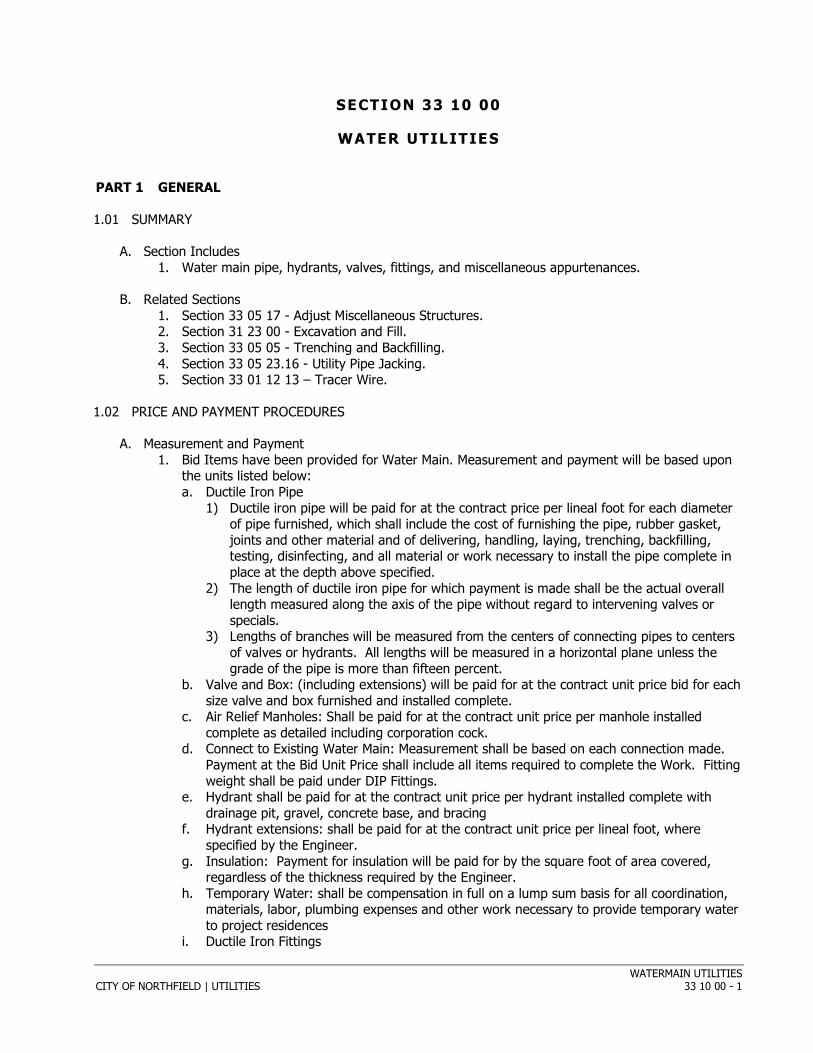
1) Ductile iron pipe will be paid for at the contract price per lineal foot for each diameter of pipe furnished, which shall include the cost of furnishing the pipe, rubber gasket, joints and other material and of delivering, handling, laying, trenching, backfilling, testing, disinfecting, and all material or work necessary to install the pipe complete in place at the depth above specified.
2) The length of ductile iron pipe for which payment is made shall be the actual overall length measured along the axis of the pipe without regard to intervening valves or specials.
3) Lengths of branches will be measured from the centers of connecting pipes to centers of valves or hydrants. All lengths will be measured in a horizontal plane unless the grade of the pipe is more than fifteen percent.
b. Valve and Box: (including extensions) will be paid for at the contract unit price bid for each size valve and box furnished and installed complete.
c. Air Relief Manholes: Shall be paid for at the contract unit price per manhole installed complete as detailed including corporation cock.
d. Connect to Existing Water Main: Measurement shall be based on each connection made. Payment at the Bid Unit Price shall include all items required to complete the Work. Fitting weight shall be paid under DIP Fittings.
e. Hydrant shall be paid for at the contract unit price per hydrant installed complete with drainage pit, gravel, concrete base, and bracing
f. Hydrant extensions: shall be paid for at the contract unit price per lineal foot, where specified by the Engineer.
g. Insulation: Payment for insulation will be paid for by the square foot of area covered, regardless of the thickness required by the Engineer.
h. Temporary Water: shall be compensation in full on a lump sum basis for all coordination, materials, labor, plumbing expenses and other work necessary to provide temporary water to project residences
i. Ductile Iron Fittings
WATERMAIN UTILITIES CITY OF NORTHFIELD | UTILITIES 33 10 00 - 2
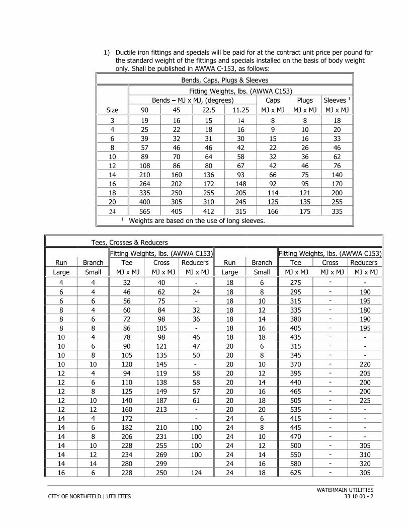
1) Ductile iron fittings and specials will be paid for at the contract unit price per pound for the standard weight of the fittings and specials installed on the basis of body weight only. Shall be published in AWWA C-153, as follows:
Bends, Caps, Plugs & Sleeves Fitting Weights, lbs. (AWWA C153) Bends – MJ x MJ, (degrees) Caps Plugs Sleeves 1
Size 90 45 22.5 11.25 MJ x MJ MJ x MJ MJ x MJ 3 19 16 15 14 8 8 18 4 25 22 18 16 9 10 20 6 39 32 31 30 15 16 33 8 57 46 46 42 22 26 46 10 89 70 64 58 32 36 62 12 108 86 80 67 42 46 76 14 210 160 136 93 66 75 140 16 264 202 172 148 92 95 170 18 335 250 255 205 114 121 200 20 400 305 310 245 125 135 255 24 565 405 412 315 166 175 335
1 Weights are based on the use of long sleeves.
Tees, Crosses & Reducers Fitting Weights, lbs. (AWWA C153) Fitting Weights, lbs. (AWWA C153)
Run Branch Tee Cross Reducers Run Branch Tee Cross Reducers Large Small MJ x MJ MJ x MJ MJ x MJ Large Small MJ x MJ MJ x MJ MJ x MJ
4 4 32 40 - 18 6 275 - - 6 4 46 62 24 18 8 295 - 190 6 6 56 75 - 18 10 315 - 195 8 4 60 84 32 18 12 335 - 180 8 6 72 98 36 18 14 380 - 190 8 8 86 105 - 18 16 405 - 195 10 4 78 98 46 18 18 435 - - 10 6 90 121 47 20 6 315 - - 10 8 105 135 50 20 8 345 - - 10 10 120 145 - 20 10 370 - 220 12 4 94 119 58 20 12 395 - 205 12 6 110 138 58 20 14 440 - 200 12 8 125 149 57 20 16 465 - 200 12 10 140 187 61 20 18 505 - 225 12 12 160 213 - 20 20 535 - - 14 4 172 - 24 6 415 - - 14 6 182 210 100 24 8 445 - - 14 8 206 231 100 24 10 470 - - 14 10 228 255 100 24 12 500 - 305 14 12 234 269 100 24 14 550 - 310 14 14 280 299 24 16 580 - 320 16 6 228 250 124 24 18 625 - 305
WATERMAIN UTILITIES CITY OF NORTHFIELD | UTILITIES 33 10 00 - 3
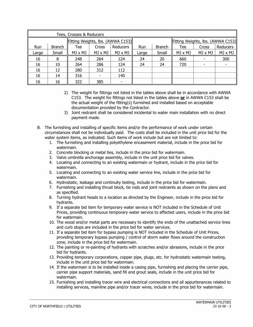
Tees, Crosses & Reducers Fitting Weights, lbs. (AWWA C153) Fitting Weights, lbs. (AWWA C153)
Run Branch Tee Cross Reducers Run Branch Tee Cross Reducers Large Small MJ x MJ MJ x MJ MJ x MJ Large Small MJ x MJ MJ x MJ MJ x MJ
16 8 248 264 124 24 20 660 - 300 16 10 264 286 124 24 24 720 - - 16 12 280 312 112 16 14 316 - 140 16 16 322 385 -
2) The weight for fittings not listed in the tables above shall be in accordance with AWWA
C153. The weight for fittings not listed in the tables above or in AWWA C153 shall be the actual weight of the fitting(s) furnished and installed based on acceptable documentation provided by the Contractor.
3) Joint restraint shall be considered incidental to water main installation with no direct payment made.
B. The furnishing and installing of specific items and/or the performance of work under certain circumstances shall not be individually paid. The costs shall be included in the unit price bid for the water system items, as indicated. Such items of work include but are not limited to:
1. The furnishing and installing polyethylene encasement material, include in the price bid for watermain.
2. Concrete blocking or metal ties, include in the price bid for watermain. 3. Valve umbrella anchorage assembly, include in the unit price bid for valves. 4. Locating and connecting to an existing watermain or hydrant, include in the price bid for
watermain. 5. Locating and connecting to an existing water service line, include in the price bid for
watermain. 6. Hydrostatic, leakage and continuity testing, include in the price bid for watermain. 7. Furnishing and installing thrust block, tie rods and joint restraints as shown on the plans and
as specified. 8. Turning hydrant heads to a location as directed by the Engineer, include in the price bid for
hydrants. 9. If a separate bid item for temporary water service is NOT included in the Schedule of Unit
Prices, providing continuous temporary water service to affected users, include in the price bid for watermain.
10. The wood and/or metal parts are necessary to identify the ends of the unattached service lines and curb stops are included in the price bid for water services.
11. If a separate bid item for bypass pumping is NOT included in the Schedule of Unit Prices, providing temporary bypass pumping / control of storm water flows around the construction zone, include in the price bid for watermain.
12. The painting or re-painting of hydrants with scratches and/or abrasions, include in the price bid for hydrants.
13. Providing temporary corporations, copper pipe, plugs, etc. for hydrostatic watermain testing, include in the unit price bid for watermain.
14. If the watermain is to be installed inside a casing pipe, furnishing and placing the carrier pipe, carrier pipe support materials, sand fill and grout seals, include in the unit price bid for watermain.
15. Furnishing and installing tracer wire and electrical connections and all appurtenances related to installing services, mainline pipe and/or tracer wires, include in the price bid for watermain.

WATERMAIN UTILITIES CITY OF NORTHFIELD | UTILITIES 33 10 00 - 4
1.03 REFERENCES
A. AWWA C-651 shall apply to the disinfecting of water mains, except as modified herein.
B. Unless noted otherwise, the provisions in this section are in addition to the referenced specification.
1.04 SUBMITTALS
A. Submit Product Data for the following items consistent with Section 01 33 00: 1. Pipe, fittings, valves, and hydrants. 2. Joint restraint and corrosion resistant coatings. 3. Temporary Water Plan 4. Tracer wire.
PART 2 PRODUCTS
2.01 GENERAL
A. The materials used in this work shall be all new, and conform to the requirements for class, kind, size and materials as specified below. The Contractor shall submit in writing a list of materials showing the manufacture and designation of all materials. This list must be approved by the Engineer. Any material not listed below must have written approval by the City Engineer before it is incorporated into the work.
2.02 DUCTILE IRON PIPE AND FITTINGS
A. Ductile iron pipe shall be designed for a minimum working pressure of 150 pounds per square inch and shall conform to the applicable dimensions, and tolerances of A.W.W.A. Specification C151, latest revision, for ductile iron pipe.
B. Ductile Iron fittings shall conform to the latest revisions of A.W.W.A. Specification C153. Mechanical or push on joints shall be allowed, however the Contractor shall be consistent in the use of the selected joint style except where required for special fittings.
C. All ductile iron pipe shall be cement lined and the maximum deflection of the pipe shall not exceed two percent (2%) of the pipe diameter to prevent cracking of the lining.
D. Weighing scales may be required to verify weight of pipe.
E. Nominal thickness of wall for ductile iron pipe shall be as follows: Size Trench Condition B Thickness Inches 6” Class 52 0.31 8” Class 52 0.33 10” Class 52 0.35 12” Class 52 0.37 14” Class 51 0.36 16” Class 51 0.37 18” Class 51 0.38 20” Class 51 0.39 24” Class 51 0.41 30” Class 51 0.43 36” Class 51 0.48
WATERMAIN UTILITIES CITY OF NORTHFIELD | UTILITIES 33 10 00 - 5
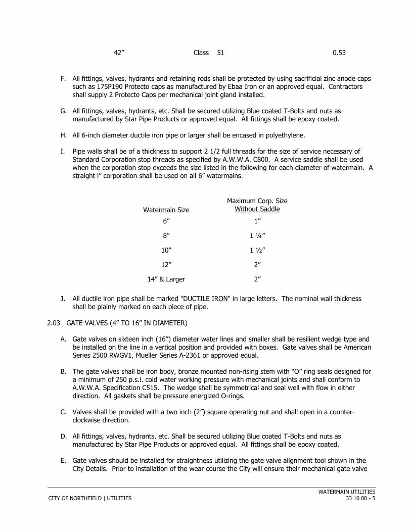
42” Class 51 0.53
F. All fittings, valves, hydrants and retaining rods shall be protected by using sacrificial zinc anode caps such as 175P190 Protecto caps as manufactured by Ebaa Iron or an approved equal. Contractors shall supply 2 Protecto Caps per mechanical joint gland installed.
G. All fittings, valves, hydrants, etc. Shall be secured utilizing Blue coated T-Bolts and nuts as manufactured by Star Pipe Products or approved equal. All fittings shall be epoxy coated.
H. All 6-inch diameter ductile iron pipe or larger shall be encased in polyethylene.
I. Pipe walls shall be of a thickness to support 2 1/2 full threads for the size of service necessary of Standard Corporation stop threads as specified by A.W.W.A. C800. A service saddle shall be used when the corporation stop exceeds the size listed in the following for each diameter of watermain. A straight l” corporation shall be used on all 6” watermains.
Watermain Size Maximum Corp. Size
Without Saddle
6” 1”
8” 1 ¼”
10” 1 ½”
12” 2”
14” & Larger 2”
J. All ductile iron pipe shall be marked "DUCTILE IRON" in large letters. The nominal wall thickness shall be plainly marked on each piece of pipe.
2.03 GATE VALVES (4” TO 16” IN DIAMETER)
A. Gate valves on sixteen inch (16”) diameter water lines and smaller shall be resilient wedge type and be installed on the line in a vertical position and provided with boxes. Gate valves shall be American Series 2500 RWGV1, Mueller Series A-2361 or approved equal.
B. The gate valves shall be iron body, bronze mounted non-rising stem with “O” ring seals designed for a minimum of 250 p.s.i. cold water working pressure with mechanical joints and shall conform to A.W.W.A. Specification C515. The wedge shall be symmetrical and seal well with flow in either direction. All gaskets shall be pressure energized O-rings.
C. Valves shall be provided with a two inch (2”) square operating nut and shall open in a counter-clockwise direction.
D. All fittings, valves, hydrants, etc. Shall be secured utilizing Blue coated T-Bolts and nuts as manufactured by Star Pipe Products or approved equal. All fittings shall be epoxy coated.
E. Gate valves should be installed for straightness utilizing the gate valve alignment tool shown in the City Details. Prior to installation of the wear course the City will ensure their mechanical gate valve
WATERMAIN UTILITIES CITY OF NORTHFIELD | UTILITIES 33 10 00 - 6
wrench is able to access the gate valve nut. Any valves deemed inaccessible will require the valve box to be replaced.
F. All bonnet, packing and operating nut bolting to be 304 or 316 Stainless Steel.
2.04 VALVE BOXES
A. Valve boxes shall be ductile iron of the three (3) piece type suitable for a depth of 7 ½ feet of cover over the top of the pipe or to a depth as shown on the plans. Shafts shall be 5 ¼ inch diameter, bases may be round or oval and length of adjustment shall be screw type. Valve boxes shall be manufactured by PowerSeal and include the valve box aligner, or by an approved equal manufacturer. Drop covers on valve boxes shall bear the word "water" on the top.
B. In case of either over depth or less depth than 7.5 feet the valve boxes shall be supplied in such a manner in order to allow a minimum of six (6) inches of adjustment both ways.
2.05 HYDRANTS
A. All hydrants shall be Clow Medallion, and shall be in accordance with the standard A.W.W.A. Specification C502, latest revision, for hydrants except as otherwise provided herein to suit local requirements. The hydrant shall be supplied with a 16” breakoff section.
B. Hydrants are to have a five (5) inch minimum valve opening. They shall be equipped with two - 2 1/2 inch hose connections and one - 4 inch pumper connection (T.P. 40500). The 2 ½” connections shall have National Standard threads (T.P. 7532). The threads are 3 1/16”, O.D. by 7 1/2 threads per inch. The four (4) inch pumper connection shall have threads as follows: four (4) inch threads, five (5) inch O.D. by four (4) threads per inch.
C. “O” ring seals shall be provided to prevent water from reaching the operating mechanism. Operating mechanism shall be lubricated through an opening in the operating nut. All moving parts are to be bronze or a non-corrodible metal.
D. Hydrant length shall be suitable for 8.0 feet depth of cover over the centerline of the cast iron lead pipes and a distance of 23"-25” from the grade or sidewalk line to the center of the outlet nozzles.
E. Each hydrant shall have a safety stem coupling and safety flange so constructed that, if hit, the stem will not bend and the hydrant barrel will not break, unless otherwise specified. It shall also permit rotation for the upper barrel or addition of extension sections.
F. The hydrant main valve shall be of the compression type and shall open against the pressure. The valve shall be faced with a resilient material which resists damage by rocks and other foreign matter, and shall be so designed that together with the seat, it is removable for repairs and replaceable without digging up the hydrant.
G. The gasket shall be inset so that it will remain attached to the seat rings and will not be injured when raised or lowered. A non-corrodible drain valve shall be provided and arranged so that it will automatically drain the hydrant barrel when the main valve is closed, and prevent any leakage when the main valve is open. The drain valve shall be faced with high-grade leather, or approved equal material, or have a tapered plug and seat for positive closure. The entire drain mechanism shall be lubricated with waterproof graphite grease. The hydrant drains shall not be plugged even in areas with the water table above the drain. The City shall be responsible for plugging drains as required.
WATERMAIN UTILITIES CITY OF NORTHFIELD | UTILITIES 33 10 00 - 7
H. Hydrants shall have satisfactory self-lubricating features for the stem threads. Where the stem (valve rod) or operating nut comes in contact with the packing, it shall be bushed with bronze or non-corrodible metal, and no leakage shall be permitted under the bushed surface. All movable parts within the hydrant shall be bronze or non-corrodible metal.
I. Outlet nipples shall be of bronze or suitable non-corrodible metal securely pinned or locked-in and caulked in place.
J. Hose caps shall be provided for all outlets and must be securely attached to the barrel with a chain constructed of material not less than one-eighth (1/8) inch in diameter. A rubber washer shall be provided in each cap and set in a groove to prevent its falling out when the cap is removed. The hose cap nut shall be of the same size and shape as the top operating nut. All caps shall be lubricated with waterproof graphite grease.
K. The size and shape of the operating nut shall be the National Standard pentagon nut, measuring 1 1/2 inch from point to flat.
L. Hydrants shall open to the left (counter clockwise) and shall be marked with an arrow to show the direction of opening. The hydrant shall be marked with the name of the manufacturer.
M. The bidder shall state weight of hydrant complete, and shall furnish detail working drawings, specifications, and description of hydrants which they propose to furnish.
N. All hydrants shall have a six (6) inch mechanical joint or slip on joint inlet for connecting to a six (6) inch ductile iron lead from the main. There shall be a gate valve between the hydrant and the watermain or lateral. The hydrant, gate valve and tee shall be installed with Mega-Lugs.
O. All new hydrants installed shall be equipped with a hyrdafinder fiberglass shaft, or approved equal.
2.06 RETAINER GLANDS
A. All retainer glands shall be ductile iron with set screws similar to American Double-X mechanical joint retainer glands or approved equal and shall be suitable for 150 p.s.i. working pressure.
B. Set screws shall be capable of withstanding torque of not less than 80-foot pounds.
2.07 ELECTRICAL CONDUCTIVITY MATERIALS
A. All joints on pipe and fittings shall be connected with an electrical conducting copper strap, clips or cable designed and tested to withstand 400 amps.
B. No external clips on gaskets shall be allowed.
2.08 TEMPORARY WATER SYSTEM
A. Distribution pipe shall Aquamine type or an approved equal.
B. No garden hose will be acceptable for use in the distribution system.
2.09 AIR RELIEF MANHOLES
A. Air relief manholes shall be constructed using precast sections conforming to ASTM Specifications C478.
WATERMAIN UTILITIES CITY OF NORTHFIELD | UTILITIES 33 10 00 - 8
B. The standard manhole casting shall be Neenah Factory No. R-1642B and shall have two concealed pick holes. The minimum allowable weight shall be 350 pounds.
C. Lettering on the manhole castings shall be as shown on the Standard Plate.
D. All castings shall conform to the requirements and dimensions shown on the drawings. All covers must fit closely in the rings in any and all positions and, when placed in the rings, must fit the ring solidly in all positions so that there will be no rocking from pressure applied on any point of the cover.
2.10 MORTAR
A. Mortar shall consist of a mixture of one-part Portland Hydraulic Cement and two parts of a clean washed sand by volume.
B. The quantity of mortar in the mixtures shall be sufficient to produce a stiff workable mortar, but in no case shall exceed 5 1/2 gallons of water per sack of cement.
C. Sand shall conform to ASTM C-144.
D. Portland Cement shall conform to ASTM C-150.
2.11 CONCRETE
A. Concrete to be used shall be composed of a mixture of fine and coarse aggregate and a Portland Hydraulic Cement conforming to the ASTM Specification Designation C-150, Type 1, with the proper water-cement ratio to obtain a concrete testing not less than 3,000 pounds per square inch in 28 days.
B. The fine aggregate for concrete shall be composed of a clean washed sand of hard, sharp, durable particles. Coarse aggregate for concrete shall be composed of a gravel uniformly graded 3/4-inch maximum size to #4 sieve.
C. Coarse aggregate shall be composed of hard durable particles free of shale, chert, flat or elongated pieces.
D. Fine and coarse aggregate shall conform to the ASTM Specification for Concrete Aggregates, Design C-33. Mixing water shall be suitable for drinking purposes, containing no acids, alkalies, oils or other deleterious materials.
E. Concrete shall be mixed in a mechanically operated mixer so controlled that the drum shall operate a minute and one half after all materials including water are in the drum. Concrete mixtures shall conform to Mn/DOT Specification 2461.
F. The slump shall not exceed four (4) inches plus or minus one (1) inch.
2.12 STEEL REINFORCING BARS
A. Steel reinforcing bars shall be deformed steel bars with epoxy coating for concrete reinforcement in conformance with ASTM Designation A-615 and ASTM Designation A-15 Intermediate Grade Billet Steel.
2.13 SOIL MATERIALS
WATERMAIN UTILITIES CITY OF NORTHFIELD | UTILITIES 33 10 00 - 9
A. NORMAL "FILL MATERIAL" 1. Is defined under the backfilling specification 9.05 of the Watermain Specifications.
B. GRANULAR SELECTED MATERIAL 1. Mn/DOT Specification 3149 aggregate shall be used for granular selected material as shown
and specified under the pipe bedding classification or an equivalent natural granular soil.
C. FINE GRANULAR FILL MATERIAL 1. This material shall consist of sound durable particles without cohesion of clean sand and/or
well rounded gravel. 2. The largest size of gravel which may be used shall be dependent upon the size of the pipe use. 3. Maximum of 3/8 inch gravel may be used when the pipe diameter exceeds 24 inches.
D. CLASS 4 AND CLASS 5 SAND AND GRAVEL 1. Class 4 and Class 5 sand and gravel shall be in conformance with Mn/DOT Specification 3138.
E. CRUSHED ROCK 1. The material shall consist of durable crushed quarry rock of which 100% passes a 2” sieve and
of which 95% is retained on a #4 sieve size. 2. Shall not contain soil overburden, sod, roots, plants, and other organic matter, or any other
materials considered objectionable by the Engineer.
F. PIT RUN GRAVEL 1. The material shall consist of sound, durable particles of gravel and sand with which may be
included limited amounts of fine soil particles as binding material, and of which 100% passes a 2” sieve and of which 90% is retained on the #200 sieve size. It shall not contain sod, roots, plants, and other organic matter, or any other objectionable materials.
G. CRUSHED ROCK OR PEA GRAVEL 1. Coarse granular pipe bedding material shall be a well graded crushed rock or pea gravel of
which 100% passes a 3/8 inch sieve and a maximum of 5% passes a No. 10 sieve. 2. Shall not contain sod, roots, plants and other organic matter, or any other objectionable
materials.
H. COARSE FILTER AGGREGATE 1. Coarse filter aggregate material, to be used as granular foundation per CEAM Spec. 2621.2F or
to be used beneath sanitary sewer and storm sewer structures or to be used as the gravel pit material below hydrants, shall be per Mn/DOT Spec. 3149.2H as determined by the Engineer.
2. Course filter aggregate material shall also be used for surfacing due to wet conditions or other such uses.
I. AGGREGATE BEDDING 1. The aggregate bedding material to be used for granular bedding and granular encasement
purposes as defined by CEAM Spec. 2621.2F, shall be per Mn/DOT Spec. 3149.
2.14 TRACER WIRE
A. Wire 1. Copper Clad Steel (CCS) Tracer Wire 2. Open Trench
a. Copperhead #12 AWG Copper Clad Steel, High Strength with minimum 450 lb. break load, with minimum 30 mil HDPE insulation thickness, part #1230*-**, or approved equal.
3. Directional Drilling/Boring
WATERMAIN UTILITIES CITY OF NORTHFIELD | UTILITIES 33 10 00 - 10
a. Copperhead 12 AWG Copper Clad Steel, Extra High Strength with minimum 1,150 lb. break load, with minimum 30 mil HDPE insulation thickness, part #1245*-** or approved equal.
4. Pipe Bursting/Slip Lining Copperhead SoloShot Extreme Strength 7 x 7 Stranded Copper Clad Steel, Extreme Strength
with 4,700 lb. break load, with minimum 50 ml HDPE insulation thickness, part # PBX-50*-**
* DENOTES COLOR: B=BLUDE, G=GREEN, P=PURPLE ** DENOTES SPOOL SIZE. 500’ 1000’ 2500’
5. All tracer wire and trace wire products shall be domestically manufactured in the U.S.A. All trace wire shall have HDPE insulation intended for direct bury, color coated per APWA standard for the specific utility being marked.
B. Termination/Access 1. All trace wire termination points must utilize an approved trace wire access box (above ground
access box or grade level/in-ground access box as applicable), specifically manufactured for this purpose.
2. Non-Roadway access boxes applications: Trace wire access boxes Grade level Copperhead adjustable lite duty Part # LD14*TP or approved equal.
3. Concrete / Driveway access box applications: Trace wire access boxes Grade level Copperhead Part # CD14*TP 14” or approved equal.
4. Fire hydrant trace wire access box applications: Above ground two terminal Cobra Test Station, denotes “F” includes hydrant mounting flange. with 1” conduit. Copperhead part # T2*-FLPKG-5/8 to fit hydrants with 5/8’’ bolts and T2*-FLPKG-3/4 to fit hydrants with ¾’’ bolts.
5. All grade level/in-ground access boxes shall be appropriately identified with “sewer” or “water” cast into the cap and be color coded.
6. All trace wire access boxes must include a manually interruptible conductive/connective link between the terminal(s) for the trace wire connection and the terminal for the grounding anode wire connection.
C. GROUNDING 1. Drive in Magnesium Anode: Copperhead Part # ANO-12 (1.5 lb) or approved equal. 2. Grounding of trace wire shall be achieved by use of a drive-in magnesium grounding anode rod
with a minimum of 20ft of #12 red HDPE insulated copper clad steel wire connected to anode (minimum 0.5 lb.) specifically manufactured for this purpose, and buried at the same elevation as the utility.
D. Connectors 1. Copperhead 3-way locking connector part # LCS1230* or approved equal. 2. DryConn 3-way Direct Bury Lug: Copperhead Part #3WB-01
E. Prohibited Products and Methods 1. Uninsulated trace wire 2. Trace wire insulations other than HDPE 3. Trace wires not domestically manufactured 4. Non locking, friction fit, twist on or taped connectors 5. Brass or copper ground rods 6. Wire connections utilizing taping or spray-on waterproofing 7. Looped wire or continuous wire installations, that has multiple wires laid side-by-side or in
close proximity to one another 8. Trace wire wrapped around the corresponding utility 9. Brass fittings with trace wire connection lugs 10. Wire terminations within the roadway, i.e. in valve boxes, cleanouts, manholes, etc. 11. Connecting trace wire to existing conductive utilities
WATERMAIN UTILITIES CITY OF NORTHFIELD | UTILITIES 33 10 00 - 11
2.15 TREATED WOOD PILING
A. All treated timber piling shall conform to Mn/DOT Specification 3471.
B. HANDLING 1. The handling of treated piling, wood caps and saddles shall be subject to the following
requirements. 2. The use of chains, cant hooks, pickaroons, peaveys, or other pointed hooks in handling piles,
shall be prohibited, excepting end hooks, cable or rope slings shall be used in loading, and proper blocking shall be used to support the material during the wrapping and removal of slings.
3. Avoid handling that will cause sudden dropping, breaking of outer fibers, bruising, or penetrating surfaces. Give cut or damaged surfaces, including tops of piles after "heading" a brush treatment of hot creosote oil in such quantities as will fill shakes, splits and penetrate thoroughly cut surfaces.
C. PILE DESIGN AND CAPACITY 1. Pile lengths are based on 20-foot lengths furnished and driven. Pile design is based on 20-ton
capacity. From results of "Capacity" tests, the piling will be designed as to actual lengths required. All piling shall be designed for at least twelve (12) inch over length for cutting at required cut-off elevation.
2. Longer piles shall be provided where required to provide specific bearing capacities. Where specified bearing capacities are attained with pile lengths less than designed effective lengths, shorter piles may be used as approved.
3. Except for capacity test purposes, piles should not be ordered until design pile lengths have been verified.
4. The capacity of driven piles shall be computed by the following formula for piles driven by single or double acting steam or air hammers, or a comparable formula as designated by the Project Engineer.
P = 2 W H
S + C
P - ALLOWABLE LOAD IN POUNDS
W - WEIGHT OF HAMMER IN POUNDS
H - HEIGHT OF ALL OF STROKE OF HAMMER IN FEET
S - AVERAGE PENETRATION IN INCHES, AVERAGED FOR THE LAST FOOT OF DRIVING
C - CONSTANT 1.0 FOR DROP HAMMER - 0.1 FOR STEAM DIESEL OR AIR HAMMERS
5. Except as otherwise indicated, all wood piles shall be driven by means of a gravity, steam, diesel or air hammer or by a combination of water jets and hammers as is approved by the Engineer. a. When gravity hammers are used, they shall weigh not less than 2,000 pounds, preferably
not less than 3,000 pounds, and in no case shall the weight of the hammer be less than the combined weight of the driving cap and the pile.

WATERMAIN UTILITIES CITY OF NORTHFIELD | UTILITIES 33 10 00 - 12
b. Steam, diesel, or air hammers shall be used whenever practicable. For piles under 50’ in length, the hammer shall develop at least 7,000 foot pounds of energy per blow, and for piles 50’ and longer shall develop at least 12,000 foot pounds of energy per blow.
6. Pile driving caps will be used when directed by the Engineer.
D. CAPACITY TEST DRIVING 1. Capacity test driving shall be as follows:
a. Test piling for determining 20-ton capacity for vertical piles and 16-ton capacity for inclined piles shall be driven as specified herein and under Section 13.06.
b. Piles shall be long enough to be driven to 20-ton capacity for vertical piles and 16-ton capacity for inclined piles. Pile shall be driven at location shown corresponding to designed piles, cut-off at elevation required, and left in place to be used as actual foundation piling. This test pile to be deducted from the total permanent piling required. Cost of pile and driving is included in proposal.
c. Install test pile with same size and type hammer operating with same effective energy and efficiency used to install permanent piles.
2.16 PILE CAPS
A. Pile caps shall be of construction grade, creosoted timber to the size and dimensions as shown on the detail plate contained in these specifications. Timber pile caps shall be fastened to the pile with 3/4” galvanized driftpins set in predrilled holes to prevent splitting. Timber members of the pile cap that crack or split during installation shall be removed and replaced at no cost to the owner.
2.17 CONTRACTOR'S RESPONSIBILITY FOR MATERIALS
A. Material Furnished by Contractor 1. The Contractor shall be responsible for all material furnished by them, and the Contractor shall
replace at their own expense all such material that is found to be defective in manufacturing or that has become damaged in handling after delivery by the manufacturer.
2. This shall include the furnishing of all material and labor required for the replacement of installed material discovered defective prior to the final acceptance of the work, or during the warranty period.
B. Material Furnished by Owner 1. The Contractor's responsibility for material furnished by the owner shall begin at the point of
delivery by the manufacturer, or owner, and upon acceptance of the material by the Contractor.
2. The Contractor shall examine all material furnished by the owner at the time and place of delivery and shall reject all defective material.
3. The point of delivery shall be stated in the "Special Provisions".
C. Replacement of Damaged Material 1. Any material furnished by the owner that becomes damaged after acceptance by the
Contractor shall be replaced by the Contractor at the Contractor's expense.
D. Responsibility for Safe Storage 1. The Contractor shall be responsible for the safe storage of material furnished by or to the
Contractor and accepted by the Contractor, and intended for the work, until it has been incorporated in the completed project.
2. The interior of all pipe, fittings, and other accessories shall be kept free from dirt and foreign matter at all times.

WATERMAIN UTILITIES CITY OF NORTHFIELD | UTILITIES 33 10 00 - 13
3. Valves and hydrants shall be drained and stored in a manner that will protect them from damage and freezing.
E. Material Handling 1. Pipe and other accessories shall, unless otherwise directed in the Special Provisions, be
unloaded at the point of delivery, hauled to and distributed at the site of the project by the Contractor.
2. In distributing the material at the site, each piece shall be unloaded opposite or near the place where it is to be laid in the trench.
3. Pipe shall be so handled that the coating and lining will not be damaged. 4. If any part of the lining or coating is damaged, the repair shall be made by the Contractor, at
the Contractor's expense, in a manner satisfactory to the Engineer.
PART 3 EXECUTION
3.01 PREPARATION
A. Conform to the requirements of Section 33 05 05.
3.02 INTERRUPTION OF WATER SERVICE
A. No interruption of water service will be allowed unless approved by the City Engineer.
B. A 48-hour notice is required from the Contractor for all water shut down operations. 1. If an interruption in water service is approved, all consumers affected by the operation shall be
notified by the Northfield Water Division and be advised of the probable time when service will be restored.
2. All valves that are required to be opened or closed shall be operated only by the Northfield Public Works Department.
C. The Contractor will be required to provide temporary water service whenever possible.
3.03 TEMPORARY WATER
A. The Contractor shall be responsible (until completion of the project) for providing water to any homes that have their individual water systems become inoperative due to construction operations.
B. The temporary system shall consist of an aboveground distribution system utilizing a fire hydrant for the water source.
C. Distribution piping shall be sized such that no pressure loss is experienced at the building being served.
D. Each service line from the distribution system shall be valved such that work at the property or on the service can be performed without putting other properties out of service.
E. Service lines to individual units shall be a black poly hose with a 150 psi rating and all rib beds shall be a galvanized material that is double clamped.
F. This temporary water system shall be bacteria tested each time it is broken down and re-used. The Contractor shall be responsible for bacteria testing.
WATERMAIN UTILITIES CITY OF NORTHFIELD | UTILITIES 33 10 00 - 14
G. A passing bacteria test from an approved laboratory must be supplied to the City of Northfield Water Department before the distribution system can be turned on.
H. The Contractor shall be solely responsible for protection of water heaters, softeners or other systems (it may be necessary to bypass these items).
1. A licensed plumber shall be used for this work in buildings being served by temporary water. It will also be required that the Contractor have a contact person to repair any breaks or other problems that may occur with temporary water services during non-working hours and weekends.
2. Whoever the contact person is must be willing to do repairs immediately when they are contacted.
I. The Contractor shall coordinate necessary watermain shutdowns with the City a minimum of 24 hours in advance
3.04 PIPE ALIGNMENT AND GRADES
A. All pipe shall be laid and maintained to the required lines and grades; with hydrants, valves and fittings at the required locations; and with joints centered and drawn "home"; and with all valve and hydrant stems plumb.
B. The owner shall furnish line and grade stakes necessary for the work. 1. It shall be the Contractor's responsibility to preserve these stakes from loss or displacement. 2. The Engineer may order the replacement of any stakes deemed necessary for the proper
prosecution of the work. a. Any replacements shall be at the Contractor's expense.
C. All pipes shall be laid to the depth shown on the contract drawings.
D. The Contractor shall satisfactorily maintain the specified cover by the use of grade boards. 1. If additional bends are required, where not shown on the drawings to maintain alignment
around curves, the Contractor shall provide the required number and be compensated at the unit price as proposed on the bid form.
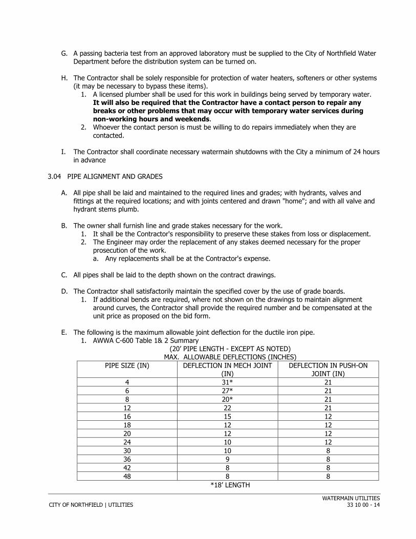
E. The following is the maximum allowable joint deflection for the ductile iron pipe. 1. AWWA C-600 Table 1& 2 Summary
(20’ PIPE LENGTH - EXCEPT AS NOTED) MAX. ALLOWABLE DEFLECTIONS (INCHES)
PIPE SIZE (IN) DEFLECTION IN MECH JOINT (IN)
DEFLECTION IN PUSH-ON JOINT (IN)
4 31* 21 6 27* 21 8 20* 21 12 22 21 16 15 12 18 12 12 20 12 12 24 10 12 30 10 8 36 9 8 42 8 8 48 8 8
*18’ LENGTH
WATERMAIN UTILITIES CITY OF NORTHFIELD | UTILITIES 33 10 00 - 15
3.05 DEVIATION WITH ENGINEER'S CONSENT
A. No deviation shall be made from the required line or grade except with the written consent of the Engineer.
3.06 DEVIATIONS OCCASIONED BY OTHER UTILITY STRUCTURES
A. Wherever existing utility structures or branch connections leading to main sewers or to main drains or other conduits, ducts, pipe or structures present obstructions to the grade and alignment of the pipe, they shall be permanently supported, removed, relocated or reconstructed by the Contractor through cooperation with the Owner of the utility, structure or obstruction involved.
1. In instances where their relocation or reconstruction is impractical, a deviation from the grade will be ordered and the change shall be made in the manner directed with extra compensation allowed therefore at unit prices, if applicable.
3.07 LAYING OF PIPE
A. Installation of Watermain and Appurtenances 1. Proper implements, tools and facilities satisfactory to the Engineer shall be provided and used
by the Contractor for the safe and convenient prosecution of the work. 2. Pipe and other materials shall be unloaded and distributed on the job in a manner approved by
the Engineer. a. No materials be thrown or dumped from the truck. b. All materials unloaded in an unsatisfactory manner shall be rejected and work shall be
stopped until such materials have been examined by the Inspector and approved. c. The Contractor shall furnish the necessary assistance in such examination of materials.
3. Watermain materials shall be carefully lowered into trench piece by piece by means of a derrick, ropes or other suitable tools or equipment, in such a manner as to prevent damage to materials and protective coatings and lining.
4. Watermain shall be installed at a minimum depth of 7 ½ feet. a. If the Contractor cannot achieve this depth due to obstructions or other such reasons, the
main shall be insulated as directed by the Engineer.
B. Laying of Pipe and Fittings 1. Before lowering and while suspended, the pipe and fittings shall be inspected for defects.
a. Any defective, damaged or unsound material shall be rejected. 2. All foreign matter or dirt shall be removed from the inside of the pipe and fittings before it is
lowered into its position in the trench, and shall be kept clean by approved means during and after laying. a. All openings along the line of the main shall be securely closed as directed, and in the
suspension of work at any time, suitable stoppers shall be placed to prevent earth or other substances from entering the main.
3. No pipe shall be laid in water or when the trench conditions are unsuitable for such work, except by written permission of the Engineer.
4. If an existing utility is shown on the plans and there is no bid item for removing and restoring, or working around the utility, the Contractor shall be required to remove and restore, or protect the utility.
5. The inverts of existing sewers (storm & sanitary), culverts, subdrains, etc. shall be protected during construction. The Contractor is responsible to inspect and clean, if necessary, all lines which have become compromised by the construction operations.
6. The trench for all flexible pipe shall be undercut six-inches below the pipe barrel to permit the installation of granular bedding or foundation material.
WATERMAIN UTILITIES CITY OF NORTHFIELD | UTILITIES 33 10 00 - 16
7. The trench for all rigid pipe shall be undercut three-inches below the pipe barrel to permit the installation of granular bedding or foundation material.
8. The Contractor shall install and operate a dewatering system to maintain all trenches free of water wherever necessary. The Contractor shall make his own subsurface investigations and determine what dewatering methods to utilize to prevent such damage.
9. The Contractor shall be responsible for any damage to adjacent structures or buildings caused by the dewatering operations.
10. Use of granular foundation material in lieu of performing dewatering is permitted. 11. All suitable excess excavated material shall remain the property of the Owner and shall be
loaded, hauled, placed and compacted at a site chosen by the Owner within 2 miles of the site. All unsuitable excess excavated material, with the exception of topsoil shall become the property of the Contractor and shall be removed from the site and disposed of at a site secured by the Contractor.
12. All excess excavated material shall become the property of the Contractor and shall be removed from the site and disposed of at a location secured by the Contractor.
C. Jointing of Pipe and Fittings 1. Ductile Iron: Jointing of mechanical joint pipe, push-on joint pipe, and fittings shall be done in
accordance with A.W.W.A. Section 9b and 9c of A.W.W.A. Specification C600 latest revision. 2. When pipes are cut in the field, the cut or straight end shall have all sharp or rough edges
removed before assembly.
D. Setting Hydrants 1. Hydrants shall be placed as located by the Engineer. 2. All hydrants shall be supported on an 8 inch concrete block or equal concrete base. 3. Each hydrant shall be braced and tied as shown on the detail drawings. 4. After each hydrant has been set, there shall be placed around the base of the hydrant, not less
than one cubic yard of crushed rock from which all fine material has been removed. 5. A layer of polyethylene, minimum 4 mil thickness, shall be carefully placed over the rock to
prevent the backfill from entering the voids in the drain rock. 6. All hydrants must be maintained in a plumb position during the backfilling operation. 7. Care shall be taken to ensure no excessive horizontal pressure is exerted on the hydrant barrel
when plumbing the hydrant.
E. Conductivity 1. Conductivity shall be provided throughout the water system by use of copper straps or
approved conductive gaskets with copper inserts. 2. All mechanical joint fittings shall be equipped with copper straps.
a. Lead tipped gaskets will not be approved for conductivity. 3. Copper jumper straps between sections of pipe shall be not less than 1/16” x 3/4” strap bolted
to shop welded pipe straps of the same size. a. Bolts shall be 5/16” diameter bronze.
4. For all locations where shop welded straps are not available, field welds shall be made using the Cadweld method with size 32 cartridge.
5. Each field weld shall be properly made after filing the surface of the pipe to a clean bare metal over the entire area of the weld.
6. Straps bolted to mechanical joint fittings shall be not less than 1/16” x 1 1/2”. 7. All straps shall be securely fastened and backfill placed so as to not damage the conductivity.
F. Sewer Crossings 1. Watermains crossing sanitary sewers shall be laid to provide a separation of at least 18 inches
between the bottom of the watermain and the top of the sewer.
WATERMAIN UTILITIES CITY OF NORTHFIELD | UTILITIES 33 10 00 - 17
2. When local conditions prevent a vertical separation as described, the following construction shall be used. a. Sewers passing over or under watermains shall be constructed of materials equal to
watermain standards of construction. b. A length of water pipe shall be centered at the point of crossing so that the joints will be
equidistant and as far as possible from the sewer.
3.08 VALVES, BOXES, MANHOLES, VAULTS, AND FITTINGS
A. Valves and fittings shall be placed where shown on the plans or as designated by the Engineer.
B. Unless otherwise specified or shown on the drawings, cast iron valve boxes shall be installed with all gate valves 16 inches or smaller.
C. Valve boxes shall be firmly supported to maintain centered and plumb alignment over the wrench nut of the valve, with box cover ¼” to ½” below the surface of the finished pavement or at such other level as may be directed by the Engineer.
D. All bends, tees, hydrants and plugs shall be securely braced against undisturbed soil using timbers, precast concrete block with wooden wedges or poured in place concrete thrust blocks.
E. The method of anchorage must be reviewed and approved by the Engineer prior to backfilling.
F. Retaining glands shall be installed at all bends.
G. On hydrants leads and on stubs for future lines, all fittings, valves and hydrants shall be tied with rods or bolts to the main line tee in accordance with the manufacturers recommendations.
1. The valve shall be tied to tee and the hydrant shall be tied to the valve as shown on the Standard Detail Plates. Mega-lugs shall be considered as an acceptable method.
3.09 WATER SERVICES
A. Curb stops and boxes shall be installed as shown on the standard plates. The curb stop and box shall be located on 1’ off of the property line on the property side, or within the 10’ front easement if applicable. All curb stops shall be on the building side of the sidewalk.
B. Corporation stops shall be tapped into the main only when full of water under pressure. No taps shall be made into a dry pipe. Corporation stops shall be turned into the pipe until tight and shall not be turned back to facilities having the operation nut on the top.
C. The copper service lines as placed between the watermains and the curb boxes shall have a minimum of 7.5 feet of cover except at the goose neck which shall have 6 1/2’ minimum cover. Therefore, service lines must be placed (incidental to the project) beneath any obstruction, which would prohibit the required cover if the service line were placed on top of said obstruction. The method of tunneling under an obstruction shall be approved by the Engineer.
D. One continuous copper line without any joint shall be installed from the corporation to the curb stop unless otherwise approved by the City Engineer. All copper pipe fittings shall be compression type.
E. Each curb box shall be marked by a 2” x 2” wooden post; extending from the bottom of the curb box to a point two feet above the ground service. All watermain taps shall be inspected by the City of Northfield or the project inspector prior to backfilling.
WATERMAIN UTILITIES CITY OF NORTHFIELD | UTILITIES 33 10 00 - 18
F. The Contractor shall furnish the inspector with ties to the services (curb stop) relating to building corners, manholes, hydrants and etc.
G. All new service lines shall be 1” Type K copper. The connection from the 1” copper line to the meter shall be a follows for each meter type:
1. 5/8” X ½” Meter: The line from the 1” copper and main shut-off valve to the meter shall be ¾” copper pipe. The fitting connecting the ¾” copper to the 5/8” X ½” tailpiece on the meter must be a brass bushing ¾” male to ½” female. This type of fitting will allow for the full 5/8” inside diameter from the ¾” copper through the water meter tailpiece. This also pertains to the house side of the meter and tailpiece. Full-flow ball valves shall be installed on both sides of the meter.
2. ¾” Meter: ¾” tailpiece may be hooked to the ¾” copper pipe with a ¾” female copper fitting. Full-flow ball valves shall be installed on both sides of the meter.
3. 1” Meter: 1” tailpiece may be hooked to the 1” copper pipe with a 1” female copper fitting. Full-flow ball valves shall be installed on both sides of the meter.
3.10 SERVICE ABANDONMENT
A. Any Water Service that is to be abandoned shall be abandoned at the main. A machine inserted threaded tapered plug H-10034 made by Mueller Companies shall be used for any services 2” or smaller. All other services shall be plugged at the main with mechanical joint plugs. Any large diameter pipe (4”or bigger) that is left in place shall be sand-filled.
B. All curb stop and boxes must also be completely removed.
3.11 INSULATION
A. Where required, insulation shall be placed directly on top of the sewer or water lines.
B. Water lines installed with less than 6’ of cover shall be insulated at the discretion of the Engineer.
C. The area adjacent to the line being insulated shall be leveled and compacted even with the top of the sewer or water pipe.
D. Special care shall be taken so that there are no irregularities in the surface the insulation will be placed on.
E. Insulation shall be installed either 3” or 6” thick depending on the depth of line being insulated. Exact thickness of insulation will be determined by the Engineer.
F. Insulation shall be placed in whole sheets (4’ X 8’) wherever possible.
G. Broken pieces and scrap pieces will not be acceptable.
H. Joints shall be overlapped.
3.12 INSTALLING PILING
A. Piles shall be installed according to the following requirements: 1. Do not install piles until excavation or fill in area they are to occupy has been completed to
indicate grade elevation. Do not install piles within 20’-0” of concrete less than seven (7) days old, unless so directed by the Engineer.

WATERMAIN UTILITIES CITY OF NORTHFIELD | UTILITIES 33 10 00 - 19
2. Locate piles to indicated lines. Install either to plumb position or to exact indicated batter. Maximum permissible deviation after driving, from indicated locations is such that the center of the pile shall be offset not more than six (6) inches. Maintain gravity center for each group of footing piles, where piles number two (2) or more, by templates or otherwise, to conform with indicated locations. The piles shall not deviate more than ½” per foot of pile length. Piles shall be driven in a manner that will minimize disturbing piling previously driven.
3. Provide proper driving caps and pile driver heads for hammers. Use suitable collars or bands where required for protection of butts against splitting, brooming and other damage when piles are driven.
4. Pile driving leads rigid enough to hold the pile in correct alignment during driving will be required for all types of hammers.
5. Install each permanent pile without interruption from first hammer blow until required penetration per blow as directed has been obtained; any deviation from this requirement will be permitted only subject to unforeseen causes. In any event, install final 25% of pile length to completion without interruption. Install piles full required length, except that if the Engineer determines indicated length of certain piles to be impracticable or undesirable, cut off such piles at depth as directed. After installation, cut off piles square at cut-off grade line; remove surplus material from site.
6. When handling or driving piles, take special precautions to prevent overstress or leading away from plumb or true position. When high resistant strata lying near surface must be penetrated, spud piles may be used to relieve long piles of hard driving during early stages of driving operations.
7. Piles that are damaged, mislocated, or driven out of alignment will be replaced with new piles as directed without additional cost to owner.
8. When driving piles in clusters, or under any conditions of relatively close spacing, make observations to determine any uplift. If uplift occurs, reinstall piles so affected to either their original resistance or elevation or both.
9. The Contractor shall keep an accurate and detailed log of each pile, indicating the depth to which the pile is driven, the rate of penetration under the last series of blows, and the general driving characteristics. A reproducible copy of the log shall be furnished to the owner.
10. Measurement shall be based on effective length of piles in place measured to nearest foot.
3.13 FIELD QUALITY CONTROL
A. PRESSURE TESTING 1. All watermain including fittings, valves, services and hydrants shall be tested in accordance
with and shall meet the requirements set forth in American Water Works Association (AWWA) Specifications C-600 latest revision.
2. The Contractor shall have the option of using an alternative testing procedure as follows: a. After the pipe has been laid including fittings, valves, hydrants, and services and the line
has been backfilled in accordance with these specifications, all newly laid pipe, or any valved section thereof, unless otherwise directed by the Engineer, shall be subjected to a hydrostatic pressure of 150 pounds per square inch.
b. The duration of each such test shall be two (2) hours. c. The allowable pressure drop shall not exceed two (2) psi in the last hour of the two (2)
hour pressure test. 3. Each valved section of pipe shall be slowly filled with water and the specified test pressure,
measured at the lowest point of elevation, shall be applied by means of a pump connected to the pipe in a satisfactory manner.
4. The pump, pipe connection, gauges and all necessary apparatus shall be furnished by the Contractor.
5. Gauges and measuring devices must meet with the approval of the Engineer and the necessary pipe taps made as directed.
WATERMAIN UTILITIES CITY OF NORTHFIELD | UTILITIES 33 10 00 - 20
a. The pressure gauge for the tests shall be an Ashcroft Model 1082 with a 4 1/2 inch dial face with one (1) psi increments or approved equal. 1) The gauge maybe tested by the City of Northfield at any time to ensure accuracy of
the gauge being used for the testing. 2) The pressure gauge shall be a standard pressure gauge. The dial shall register from 0-
200 psi and have a dial size of 4 ½ inches with 1 psi increments. 6. Before applying the specified test pressure, all air shall be expelled from the pipe.
a. Taps shall be made, if necessary, at points of highest elevations, and afterward tightly plugged.
7. The pressure testing procedure shall be set up in a manner that will allow pressure testing of each main line valve.
8. Upon completion of the watermain test, the Contractor shall proceed to test each main line valve by subjecting it to a pressure of 150 psi for five (5) minutes. a. The allowable pressure drop shall not exceed five (5) psi in the five (5) minute period.
9. Any cracked or defective pipes, fittings, valves or hydrants discovered in consequence of the pressure test shall be removed and replaced by the Contractor with sound material in the manner provided and the test shall be repeated until satisfactory to the Engineer.
B. DISINFECTING MAINS 1. After completion of the installation and testing, the Contractor shall disinfect the new pipe,
valves and fittings as described in A.W.W.A. Specification No. C-651 by use of the Continuous Feed Method.
2. The Contractor may elect to use the Tablet Method, which is generally described as follows: a. The Contractor shall place hypochlorite tablets in each section of pipe and also in hydrants,
hydrant branches and other appurtenances during construction. b. The tablets shall be attached to the top of the pipe with an adhesive of hot tar or
"Permatex" No. 2 gasket cement, or other approved material. c. When the installation has been completed, the main shall be filled with water at a velocity
of less than one (1) foot per second. d. Water shall remain in the pipe for at least 24 hours.
1) After the 24-hour retention period, the heavily chlorinated water shall be flushed from the main until the chlorine concentration in the water leaving the main is less than one (1) ppm.
3. Tests are required to determine chlorine residual at the end of the 24-hour retention period and after flushing to ascertain that the heavily chlorinated water has been removed from the pipeline. At the end of the 24-hour retention period, the main shall contain not less than 10-ppm chlorine.
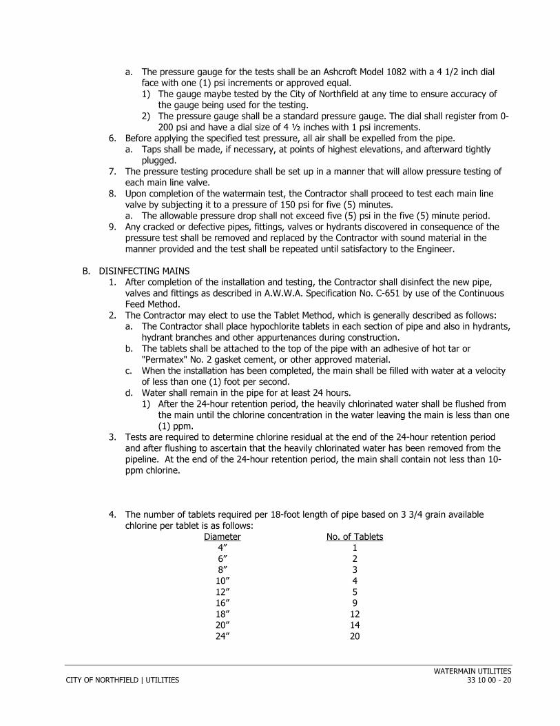
4. The number of tablets required per 18-foot length of pipe based on 3 3/4 grain available
chlorine per tablet is as follows: Diameter No. of Tablets
4” 1 6” 2 8” 3 10” 4 12” 5 16” 9 18” 12 20” 14 24” 20
WATERMAIN UTILITIES CITY OF NORTHFIELD | UTILITIES 33 10 00 - 21
5. Only fresh disinfectants shall be used and the main filled with water and flushed not later than one (1) week after the disinfectant has been added.
6. The water (containing chlorine) shall be left in the pipe, being disinfected, for a minimum of twenty-four (24) hours.
C. ELECTRICAL CONDUCTIVITY TEST 1. Conductivity test shall be performed on all mains after they have been pressure tested and are
full of water at normal operating pressure. a. A direct current of 350 amps at 30 volts shall be passed through the line for 4 minutes.
Current flow shall be measured continuously on a suitable ammeter and shall remain steady without interruption or excessive fluctuation throughout the period.
b. At the end of the four (4) minute period, the current shall be raised to 400 amps for one (1) minute without fluctuation.
c. Insufficient current or wide fluctuations of ammeter needle shall be evidence of defective conductivity, which shall be isolated, corrected and retested.
d. The connection for the conductivity shall be made either to a gate valve or to the hydrant barrel. 1) Connections shall not be made to any operating mechanism of the hydrant.
2. Acceptable equipment for the test shall be an arc-welding machine with adequate sized cables to carry the test current without voltage drop or overheating.
3. Conductivity test shall be carried out in the presence of the Engineer or the Engineer's duly authorized agent.
4. Caution shall be exercised at all times when working with electrical equipment and wires during the conductivity test.
D. BACTERIA TESTING 1. After the water line has been tested at 150 psi for two hours, the Northfield Water Division will
flush the line and allow the contractor to obtain a sample. 2. The Water Division staff will load, flush, and operate all new watermain valves and hydrants.
If the Water Division is short of staff, they may elect to have the Contractor assist with these tasks.
E. DIP SPRINKLER SERVICES 1. Any DIP line that is run into a building for Fire Protection shall be tested in the same manner
as a street watermain. The service shall be run into the building and tested before any other lines are hooked up to it.
F. Tracer Wire Testing a. All new trace wire installations shall be located using typical low frequency (512Hz) line
tracing equipment, witnessed by the contractor, engineer and facility owner as applicable, prior to acceptance of ownership.
b. This verification shall be performed upon completion of rough grading and again prior to final acceptance of the project.
c. Continuity testing in lieu of actual line tracing shall not be accepted.
3.14 FAILURE TO REPLACE DEFECTIVE PARTS
A. Should the Contractor fail to make good the defective parts within a period of thirty (30) days of such notification, after written notice has been given to the Contractor, the owner may replace these parts, charging the expense of same to the Contractor.
END OF S ECT ION
Related Documents