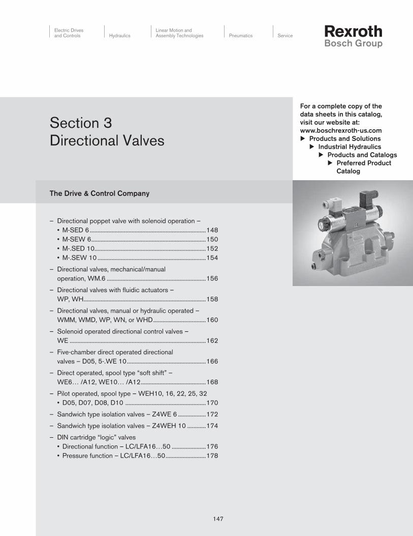
147 Electric Drives and Controls Hydraulics Linear Motion and Assembly Technologies Pneumatics Service The Drive & Control Company For a complete copy of the data sheets in this catalog, visit our website at: www.boschrexroth-us.com u Products and Solutions u Industrial Hydraulics u Products and Catalogs u Preferred Product Catalog 147 – Directional poppet valve with solenoid operation – • M-SED 6 ........................................................................... 148 • M-SEW 6.......................................................................... 150 • M-.SED 10........................................................................ 152 • M-.SEW 10 ...................................................................... 154 – Directional valves, mechanical/manual operation, WM.6 ................................................................ 156 – Directional valves with fluidic actuators – WP, WH............................................................................... 158 – Directional valves, manual or hydraulic operated – WMM, WMD, WP, WN, or WHD .................................. 160 – Solenoid operated directional control valves – WE ........................................................................................ 162 – Five-chamber direct operated directional valves – D05, 5-.WE 10 ................................................... 166 – Direct operated, spool type “soft shift” – WE6… /A12, WE10… /A12 .......................................... 168 – Pilot operated, spool type – WEH10, 16, 22, 25, 32 • D05, D07, D08, D10 .................................................... 170 – Sandwich type isolation valves – Z4WE 6 .................. 172 – Sandwich type isolation valves – Z4WEH 10 ............ 174 – DIN cartridge “logic” valves • Directional function – LC/LFA16…50 ...................... 176 • Pressure function – LC/LFA16…50 .......................... 178 Section 3 Directional Valves

Welcome message from author
This document is posted to help you gain knowledge. Please leave a comment to let me know what you think about it! Share it to your friends and learn new things together.
Transcript
147
Electric Drivesand Controls Hydraulics
Linear Motion andAssembly Technologies Pneumatics Service
The Drive & Control Company
For a complete copy of the
data sheets in this catalog,
visit our website at:
www.boschrexroth-us.com
u Products and Solutions
u Industrial Hy drau lics
u Products and Catalogs
u Preferred Product
Catalog
147
– Directional poppet valve with solenoid operation –
• M-SED 6 ...........................................................................148
• M-SEW 6 ..........................................................................150
• M-.SED 10........................................................................152
• M-.SEW 10 ......................................................................154
– Directional valves, mechanical/manual
operation, WM.6 ................................................................156
– Directional valves with fl uidic actuators –
WP, WH ...............................................................................158
– Directional valves, manual or hydraulic operated –
WMM, WMD, WP, WN, or WHD ..................................160
– Solenoid operated directional control valves –
WE ........................................................................................162
– Five-chamber direct operated directional
valves – D05, 5-.WE 10 ...................................................166
– Direct operated, spool type “soft shift” –
WE6… /A12, WE10… /A12 ..........................................168
– Pilot operated, spool type – WEH10, 16, 22, 25, 32
• D05, D07, D08, D10 ....................................................170
– Sandwich type isolation valves – Z4WE 6 ..................172
– Sandwich type isolation valves – Z4WEH 10 ............174
– DIN cartridge “logic” valves
• Directional function – LC/LFA16…50 ......................176
• Pressure function – LC/LFA16…50 ..........................178
Section 3
Directional Valves
Directional Valves 148 Section 3
Electric Drivesand Controls Hydraulics
Linear Motion andAssembly Technologies Pneumatics Service
See Section 16 for applicable
Preferred/Spotlight part numbers
and unit price.
3 actuator ports
4 actuator ports
= 3
= 4
Poppet valve
Nominal size 6 = 6
Actuator ports 3 4
Symbols
a b
A
P T
a b — = UK
ab
A
P T
a b — = CK
a b
A
P T
a b
B
— = D
a
b
A
P T
a b
B
— = Y
= available
Series 10 to 19 = 1X
(10 to 19: externally interchangeable)
Operating pressure 350 bar (5000 PSI) = 350
Wet pin solenoid with removable coil = C
Ordering code
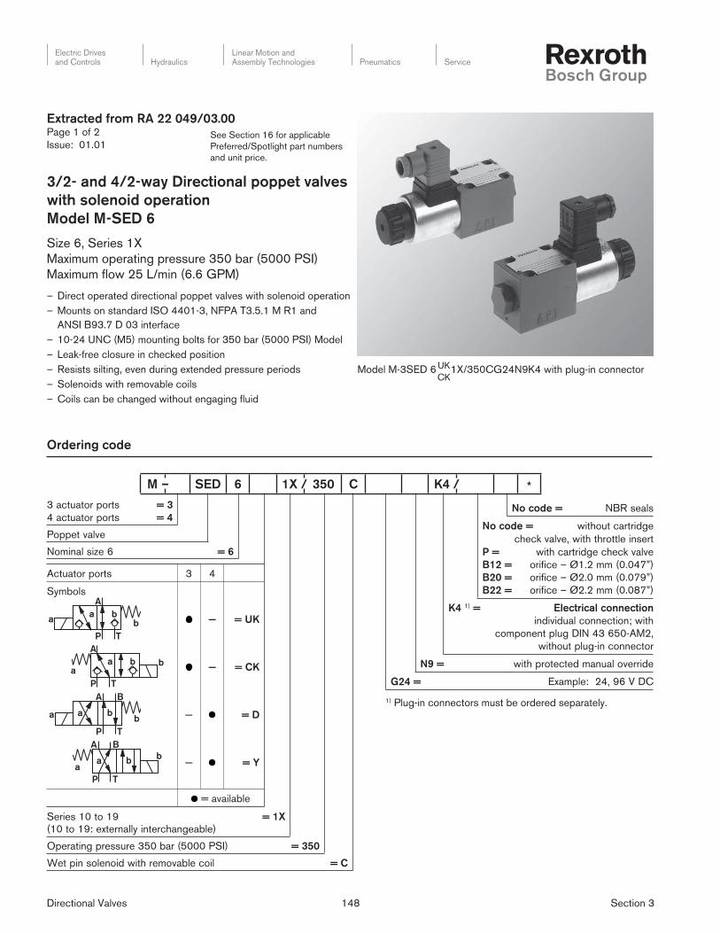
Extracted from RA 22 049/03.00Page 1 of 2
Issue: 01.01
3/2- and 4/2-way Directional poppet valves
with solenoid operation
Model M-SED 6
Size 6, Series 1X
Maximum operating pressure 350 bar (5000 PSI)
Maximum fl ow 25 L/min (6.6 GPM)
– Direct operated directional poppet valves with solenoid operation
– Mounts on standard ISO 4401-3, NFPA T3.5.1 M R1 and
ANSI B93.7 D 03 interface
– 10-24 UNC (M5) mounting bolts for 350 bar (5000 PSI) Model
– Leak-free closure in checked position
– Resists silting, even during extended pressure periods
– Solenoids with removable coils
– Coils can be changed without engaging fl uid
Model M-3SED 6 1X/350CG24N9K4 with plug-in con nec tor UK
CK
No code = NBR seals
No code = without cartridge
check valve, with throttle insert
P =
B12 =
B20 =
B22 =
with cartridge check valve
orifice – Ø1.2 mm (0.047”)
orifice – Ø2.0 mm (0.079”)
orifice – Ø2.2 mm (0.087”)
K4 1) = Electrical connection
individual connection; with
component plug DIN 43 650-AM2,
without plug-in connector
N9 = with protected manual override
G24 = Example: 24, 96 V DC
1) Plug-in connectors must be ordered separately.
M – SED 6 1X / 350 C K4 / *

Directional Valves 149 Section 3
Electric Drivesand Controls Hydraulics
Linear Motion andAssembly Technologies Pneumatics Service
See Section 16 for applicable
Preferred/Spotlight part numbers
and unit price.
Extracted from RA 22 049/03.00Page 2 of 2
Issue: 01.01
Technical data
General
Installation optional
Ambient temperature range °C (°F) –30 to +50 (–22… +122)
Weight 3/2-way directional poppet valve kg (lbs) 1.5 (3.306)
4/2-way directional poppet valve kg (lbs) 2.3 (5.069)
Hydraulic data
Max. operating pressure bar (PSI) see table on page 7 of datasheet
Max. fl ow L/min (GPM) 25 (6.60)
Pressure fl uid
1) suitable for NBR and FPM seals
2) only suitable for FPM seals
Mineral oil (HL, HLP) to DIN 51 524 1);
fast bio-degradable pressure fl uids to VDMA 24 568 (also see
RE 90 221); HETG (rape seed oil) 1); HEPG (polyglycols) 2);
HEES (synthetic esters) 2); other pressure fl uids on request
Pressure fl uid temperature range °C (°F) –30 to +80 (–22… +176) (with NBR seals)
–20 to +80 (–4… +176) (with FPM seals)
Viscosity range mm2/s (SUS) 2.8 to 500 (35 to 2320)
Degree of contamination Maximum permissible degree of contamination of the pressure
fl uid is to NAS 1638 class 9. We, therefore, recommend a fi lter
with a minimum retention rate of ß10 ≥ 75.
Electrical data
Voltage type DC
Available voltages V 24, 96
Voltage tolerance (nominal voltage) % ±10
Power consumption W 30
Duty continuous
Switching time to ISO 6403 see table below
Switching frequency cycles/h up to 15000 operations per hour, see table below
Protection to DIN 40 050 IP 65
Max. coil temperature 3) °C (°F) …150 (302)
3) Due to the occurring surface temperature of the so le noid coils,
the European standards EN563 and EN982 must be taken
into account!
When connecting the electrics, the protective
conductor (PE ) must be connected according to
the relevant regulations.
Directional Valves 150 Section 3
Electric Drivesand Controls Hydraulics
Linear Motion andAssembly Technologies Pneumatics Service
See Section 16 for applicable
Preferred/Spotlight part numbers
and unit price.
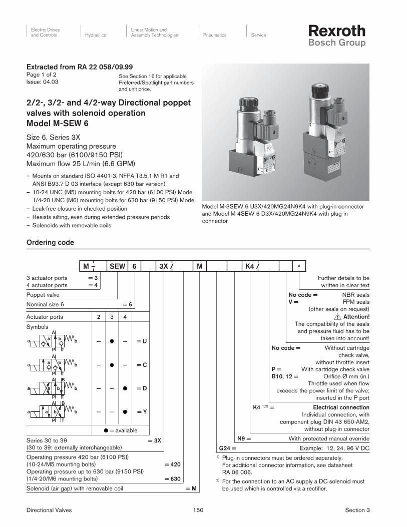
Ordering code
Extracted from RA 22 058/09.99Page 1 of 2
Issue: 04.03
2/2-, 3/2- and 4/2-way Directional poppet
valves with solenoid operation
Model M-SEW 6
Size 6, Series 3X
Maximum operating pressure
420/630 bar (6100/9150 PSI)
Maximum fl ow 25 L/min (6.6 GPM)
– Mounts on standard ISO 4401-3, NFPA T3.5.1 M R1 and
ANSI B93.7 D 03 interface (except 630 bar version)
– 10-24 UNC (M5) mounting bolts for 420 bar (6100 PSI) Model
1/4-20 UNC (M6) mounting bolts for 630 bar (9150 PSI) Model
– Leak-free closure in checked position
– Resists silting, even during extended pressure periods
– Solenoids with removable coils
Further details to be
written in clear text
No code = NBR seals
V = FPM seals
(other seals on request)
Attention!
The compatibility of the seals
and pressure fluid has to be
taken into account!
No code = Without cartridge
check valve,
without throttle insert
P =
B10, 12 =
With cartridge check valve
Orifice Ø mm (in.)
Throttle used when flow
exceeds the power limit of the valve;
inserted in the P port
K4 1;2) = Electrical connection
Individual connection, with
component plug DIN 43 650-AM2,
without plug-in connector
N9 = With protected manual override
G24 = Example: 12, 24, 96 V DC
1) Plug-in connectors must be ordered separately.
For additional connector information, see datasheet
RA 08 006.
2) For the connection to an AC supply a DC solenoid must
be used which is controlled via a rectifi er.
Model M-3SEW 6 U3X/420MG24N9K4 with plug-in connector
and Model M-4SEW 6 D3X/420MG24N9K4 with plug-in
connector
3 actuator ports
4 actuator ports
= 3
= 4
Poppet valve
Nominal size 6 = 6
Actuator ports 2 3 4
SymbolsA
TP
a ba b — — = U
A
TP
a ba b — — = C
BA
TP
a ba b — — = D
BA
TP
a ba b
— — = Y
= available
Series 30 to 39 = 3X
(30 to 39: externally interchangeable)
Operating pressure 420 bar (6100 PSI)
(10-24/M5 mounting bolts)
Operating pressure up to 630 bar (9150 PSI)
(1/4-20/M6 mounting bolts)
= 420
= 630
Solenoid (air gap) with removable coil = M
M – SEW 6 3X / M K4 / *
Directional Valves 151 Section 3
Electric Drivesand Controls Hydraulics
Linear Motion andAssembly Technologies Pneumatics Service
See Section 16 for applicable
Preferred/Spotlight part numbers
and unit price.
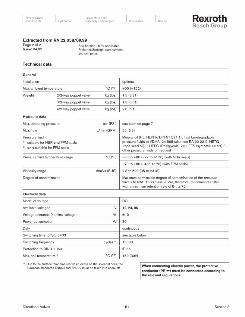
Technical data
Extracted from RA 22 058/09.99Page 2 of 2
Issue: 04.03
General
Installation optional
Max. ambient temperature °C (°F) +50 (+122)
Weight 2/2-way poppet valve kg (lbs) 1.5 (3.31)
3/2-way poppet valve kg (lbs) 1.5 (3.31)
4/2-way poppet valve kg (lbs) 2.3 (5.1)
Hydraulic data
Max. operating pressure bar (PSI) see table on page 7
Max. fl ow L/min (GPM) 25 (6.6)
Pressure fl uid1) suitable for NBR and FPM seals2) only suitable for FPM seals
Mineral oil (HL, HLP) to DIN 51 524 1); Fast bio-degradable
pressure fl uids to VDMA 24 568 (also see RA 90 221); HETG
(rape seed oil) 1); HEPG (Polyglycols) 2); HEES (synthetic esters) 2);
other pressure fl uids on request
Pressure fl uid temperature range °C (°F) –30 to +80 (–22 to +176) (with NBR seals)
–20 to +80 (–4 to +176) (with FPM seals)
Viscosity range mm2/s (SUS) 2.8 to 500 (35 to 2318)
Degree of contamination Maximum permissible degree of contamination of the pressure
fl uid is to NAS 1638 class 9. We, therefore, recommend a fi lter
with a minimum retention rate of ß10 ≥ 75.
Electrical data
Model of voltage DC
Available voltages V 12, 24, 96
Voltage tolerance (nominal voltage) % ±10
Power consumption W 30
Duty continuous
Switching time to ISO 6403 see table below
Switching frequency cycles/h 15000
Protection to DIN 40 050 IP 65
Max. coil temperature 3) °C (°F) 150 (302)
3) Due to the surface temperatures which occur on the solenoid coils, the
European standards EN563 and EN982 must be taken into account!When connecting electric power, the protective
conductor (PE ) must be connected according to
the relevant regulations.

Directional Valves 152 Section 3
Electric Drivesand Controls Hydraulics
Linear Motion andAssembly Technologies Pneumatics Service
See Section 16 for applicable
Preferred/Spotlight part numbers
and unit price.
Ordering code
Extracted from RA 22 045/03.00Page 1 of 2
Issue: 01.01
3/2- and 4/2-way Directional poppet valves
with solenoid operation
Model M-.SED 10
Size 10, Series 1X
Maximum operating pressure 350 bar (5000 PSI)
Maximum fl ow 40 L/min (10.6 GPM)
– Direct operated directional poppet valve with solenoid actuation
– Mounts on standard ISO 4401-5, NFPA T3.5.1 M R1 and
ANSI B 93.7 D 05 interface
subplates to datasheet RA 45 054 (separate order)
– Leak-free closure in checked position
– Switching is ensured even when under pressure for
long periods of time
– Solenoid coil can be rotated by 90°
– Coils can be changed without engaging fl uid
– Individual electrical connection
– With protected manual override, standard “N9”
Model M-3SED 10 1X/350CG24N9K4 with plug-in con nec tor UK CK
Further details to be
written in clear text
No code = NBR seals
No code =
P =
without cartridge
check valve,
without throttle insert
with cartridge check valve
K4 1) =
Electrical connection
individual connection; with
component plug DIN 43 650-AM2,
without plug-in connector
N9 = with protected manual override
G24 = Example: 24, 96 V DC
C = Wet pin solenoid with removable coil
350 = Operating pressure 350 bar (5000 PSI)
1X = Series 10 to 19
(10 to 19: externally interchangeable)
1) Plug-in connectors must be ordered separately.
M – SED 10 1X / 350 C K4 / *
3 actuator ports
4 actuator ports
= 3
= 4
Poppet valve
Nominal size 6 = 10
Actuator ports 3 4
Symbols
a b
A
P T
a b — = UK
ab
A
P T
a b — = CK
a b
A
P T
a b
B
— = D
a
b
A
P T
a b
B
— = Y
= available
Directional Valves 153 Section 3
Electric Drivesand Controls Hydraulics
Linear Motion andAssembly Technologies Pneumatics Service
See Section 16 for applicable
Preferred/Spotlight part numbers
and unit price.
Technical data
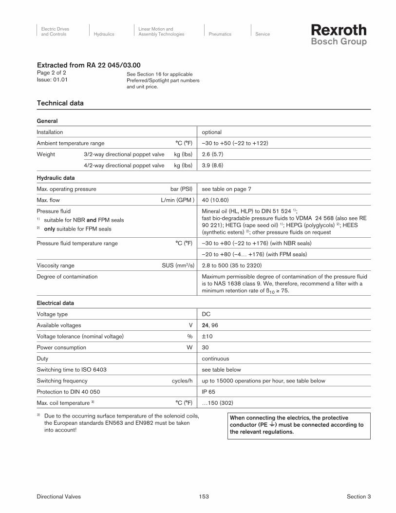
Extracted from RA 22 045/03.00Page 2 of 2
Issue: 01.01
General
Installation optional
Ambient temperature range °C (°F) –30 to +50 (–22 to +122)
Weight 3/2-way directional poppet valve kg (lbs) 2.6 (5.7)
4/2-way directional poppet valve kg (lbs) 3.9 (8.6)
Hydraulic data
Max. operating pressure bar (PSI) see table on page 7
Max. fl ow L/min (GPM ) 40 (10.60)
Pressure fl uid
1) suitable for NBR and FPM seals
2) only suitable for FPM seals
Mineral oil (HL, HLP) to DIN 51 524 1);
fast bio-degradable pressure fl uids to VDMA 24 568 (also see RE
90 221); HETG (rape seed oil) 1); HEPG (polyglycols) 2); HEES
(synthetic esters) 2); other pressure fl uids on request
Pressure fl uid temperature range °C (°F) –30 to +80 (–22 to +176) (with NBR seals)
–20 to +80 (–4… +176) (with FPM seals)
Viscosity range SUS (mm2/s) 2.8 to 500 (35 to 2320)
Degree of contamination Maximum permissible degree of contamination of the pressure fl uid
is to NAS 1638 class 9. We, therefore, recommend a fi lter with a
minimum retention rate of ß10 ≥ 75.
Electrical data
Voltage type DC
Available voltages V 24, 96
Voltage tolerance (nominal voltage) % ±10
Power consumption W 30
Duty continuous
Switching time to ISO 6403 see table below
Switching frequency cycles/h up to 15000 operations per hour, see table below
Protection to DIN 40 050 IP 65
Max. coil temperature 3) °C (°F) …150 (302)
3) Due to the occurring surface temperature of the solenoid coils,
the European standards EN563 and EN982 must be taken
into account!
When connecting the electrics, the protective
conductor (PE ) must be connected according to
the relevant regulations.
Directional Valves 154 Section 3
Electric Drivesand Controls Hydraulics
Linear Motion andAssembly Technologies Pneumatics Service
See Section 16 for applicable
Preferred/Spotlight part numbers
and unit price.
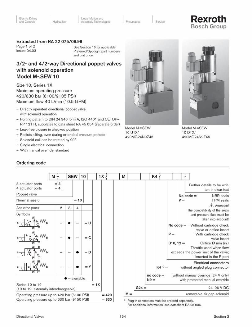
Model M-4SEW
10 D1X/
420MG24N9Z45
Model M-3SEW
10 U1X/
420MG24N9Z45
Ordering code
Extracted from RA 22 075/08.99Page 1 of 2
Issue: 04.03
3/2- and 4/2-way Directional poppet valves
with solenoid operation
Model M-.SEW 10
Size 10, Series 1X
Maximum operating pressure
420/630 bar (6100/9135 PSI)
Maximum fl ow 40 L/min (10.5 GPM)
– Directly operated directional poppet valve
with solenoid operation
– Porting pattern to DIN 24 340 form A, ISO 4401 and CETOP–
RP 121 H, subplates to data sheet RA 45 054 (separate order)
– Leak-free closure in checked position
– Resists silting, even during extended pressure periods
– Solenoid coil can be rotated by 90°
– Single electrical connection
– With manual override, standard
Further details to be writ-
ten in clear text
No code =
V =
NBR seals
FPM seals
Attention!
The compatibility of the seals
and pressure fluid must be
taken into account!
No code =
P =
B10, 12 =
Without cartridge check
valve or orifice insert
With cartridge check
valve insert
Orifice Ø mm (in.)
Throttle used when flow
exceeds the power limit of the valve;
inserted in the P port
K4 1) =
Electrical connectors
without angled plug connector
no code =
N9 =
without manual override (24 V only)
with protected manual override
G24 = 24, 96 V DC
M = removable air gap solenoid
1) Plug-in connectors must be ordered separately.
For additional information, see datasheet RA 08 006.
3 actuator ports
4 actuator ports
= 3
= 4
Poppet valve
Nominal size 6 = 10
Actuator ports 2 3 4
SymbolsA
TP
a ba b — — = U
A
TP
a ba b — — = C
BA
TP
a ba b — — = D
BA
TP
a ba b
— — = Y
= available
Series 10 to 19 = 1X
(10 to 19: externally interchangeable)
Operating pressure up to 420 bar (6100 PSI)
Operating pressure up to 630 bar (9150 PSI)
= 420
= 630
M – SEW 10 1X / M K4 / *

Directional Valves 155 Section 3
Electric Drivesand Controls Hydraulics
Linear Motion andAssembly Technologies Pneumatics Service
See Section 16 for applicable
Preferred/Spotlight part numbers
and unit price.
Extracted from RA 22 075/08.99Page 2 of 2
Issue: 04.03
Technical data
General
Mounting position optional
Ambient temperature, max. °C (°F) 50 (122)
Weight (approx.) 3/2-way poppet valve kg (lbs) 2.0 (4.40)
4/2-way poppet valve kg (lbs) 3.5 (7.71)
Hydraulic
Operating pressure, max. bar (PSI) 420/630 (6100/9135)
Flow, max. L/min (GPM) 40 (10.60)
Hydraulic fl uid
1) Suitable for NBR and FPM seals
2) Only suitable for FPM seals
Mineral oil (HL, HLP) to DIN 51 524 1); Fast bio-degradable
pressure fl uids to VDMA 24 568 (also see RA 90 221);
HETG (rape seed oil) 1); HEPG (Polyglycol) 2); HEES
(synthetic ester) 2); other fl uids on request
Fluid temperature range °C (°F) NBR seals: –30 to +80 (–22 to +172)
FPM seals: –20 to +80 (–4 to +176)
Viscosity range mm2/s (SUS) 2.8 to 500 (35 to 2320)
Maximum degree of contamination Class 18/15 according to ISO 4406. We therefore recommend
a fi lter with a minimum retention rate of ß10 ≥ 75.
Electrical
Type of supply DC
Available voltages V 24, 96
Voltage tolerance (nominal voltage) % ±10
Power requirement W 30
Duty cycle 100 %
Operating time to ISO 6403 see table
Shifting frequency Cycles/h 15000
Type of protection to DIN 40 050 IP 65
Coil temperature range °C (°F) up to 150 (302)
Directional Valves 156 Section 3
Electric Drivesand Controls Hydraulics
Linear Motion andAssembly Technologies Pneumatics Service
See Section 16 for applicable
Preferred/Spotlight part numbers
and unit price.
Ordering code
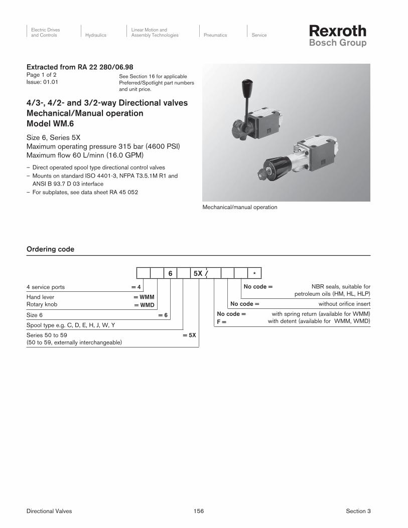
Extracted from RA 22 280/06.98Page 1 of 2
Issue: 01.01
4/3-, 4/2- and 3/2-way Directional valves
Mechanical/Manual operation
Model WM.6
Size 6, Series 5X
Maximum operating pressure 315 bar (4600 PSI)
Maximum fl ow 60 L/minn (16.0 GPM)
– Direct operated spool type directional control valves
– Mounts on standard ISO 4401-3, NFPA T3.5.1M R1 and
ANSI B 93.7 D 03 interface
– For subplates, see data sheet RA 45 052
Mechanical/manual operation
No code = NBR seals, suitable for
petroleum oils (HM, HL, HLP)
No code = without orifice insert
No code =
F =
with spring return (available for WMM)
with detent (available for WMM, WMD)
4 service ports = 4
Hand lever
Rotary knob
= WMM
= WMD
Size 6 = 6
Spool type e.g. C, D, E, H, J, W, Y
Series 50 to 59
(50 to 59, externally interchangeable)
= 5X
6 5X / *
Directional Valves 157 Section 3
Electric Drivesand Controls Hydraulics
Linear Motion andAssembly Technologies Pneumatics Service
See Section 16 for applicable
Preferred/Spotlight part numbers
and unit price.
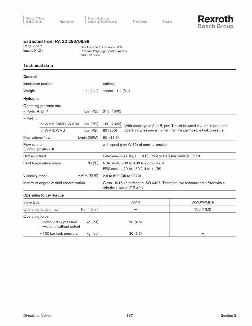
General
Installation position optional
Weight kg (lbs.) approx. 1.4 (3.1)
Hydraulic
Operating pressure max
– Ports A, B, P bar (PSI) 315 (4600)
– Port T:
for WMM, WMD, WMDA bar (PSI) 160 (2320) With spool types A or B, port T must be used as a drain port if the
operating pressure is higher than the permissible tank pressure.for WMR, WMU bar (PSI) 60 (900)
Max. volume fl ow L/min (GPM) 60 (16.0)
Flow section
(Control position 0)
with spool type W 3% of nominal section
Hydraulic fl uid Petroleum oils (HM, HL,HLP); Phosphate ester fl uids (HFD-R)
Fluid temperature range °C (°F) NBR seals: –30 to +80 (–22 to +176)
FPM seals: –20 to +80 (–4 to +176)
Viscosity range mm2/s (SUS) 2.8 to 500 (35 to 2320)
Maximum degree of fl uid contamination Class 18/15 according to ISO 4406. Therefore, we recommend a fi lter with a
retention rate of ß10 ≥ 75.
Operating force/-torque
Valve type WMM WMD/WMDA
Operating torque max. Ncm (lb-in) — 150 (13.3)
Operating force
– without tank pressure
with and without detent
kg (lbs) 20 (4.5) —
– 150 bar tank pressure kg (lbs) 30 (6.7) —
Technical data
Extracted from RA 22 280/06.98Page 2 of 2
Issue: 01.01
Directional Valves 158 Section 3
Electric Drivesand Controls Hydraulics
Linear Motion andAssembly Technologies Pneumatics Service
See Section 16 for applicable
Preferred/Spotlight part numbers
and unit price.
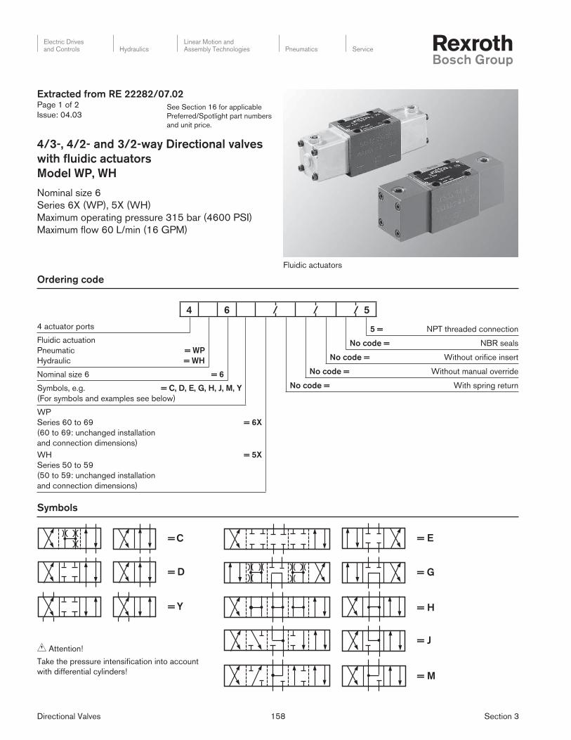
Extracted from RE 22282/07.02Page 1 of 2
Issue: 04.03
4/3-, 4/2- and 3/2-way Directional valves
with fl uidic actuators
Model WP, WH
Nominal size 6
Series 6X (WP), 5X (WH)
Maximum operating pressure 315 bar (4600 PSI)
Maximum fl ow 60 L/min (16 GPM)
Ordering code
5 = NPT threaded connection
No code = NBR seals
No code = Without orifi ce insert
No code = Without manual override
No code = With spring return
4 actuator ports
Fluidic actuation
Pneumatic
Hydraulic
= WP
= WH
Nominal size 6 = 6
Symbols, e.g. = C, D, E, G, H, J, M, Y
(For symbols and examples see below)
WP
Series 60 to 69
(60 to 69: unchanged installation
and connection dimensions)
WH
Series 50 to 59
(50 to 59: unchanged installation
and connection dimensions)
= 6X
= 5X
Symbols
Fluidic actuators
= D
= Y
= C
= M
= G
= J
= H
= E
Attention!
Take the pressure intensifi cation into account
with differential cylinders!
4 6 / / / 5
Directional Valves 159 Section 3
Electric Drivesand Controls Hydraulics
Linear Motion andAssembly Technologies Pneumatics Service
See Section 16 for applicable
Preferred/Spotlight part numbers
and unit price.
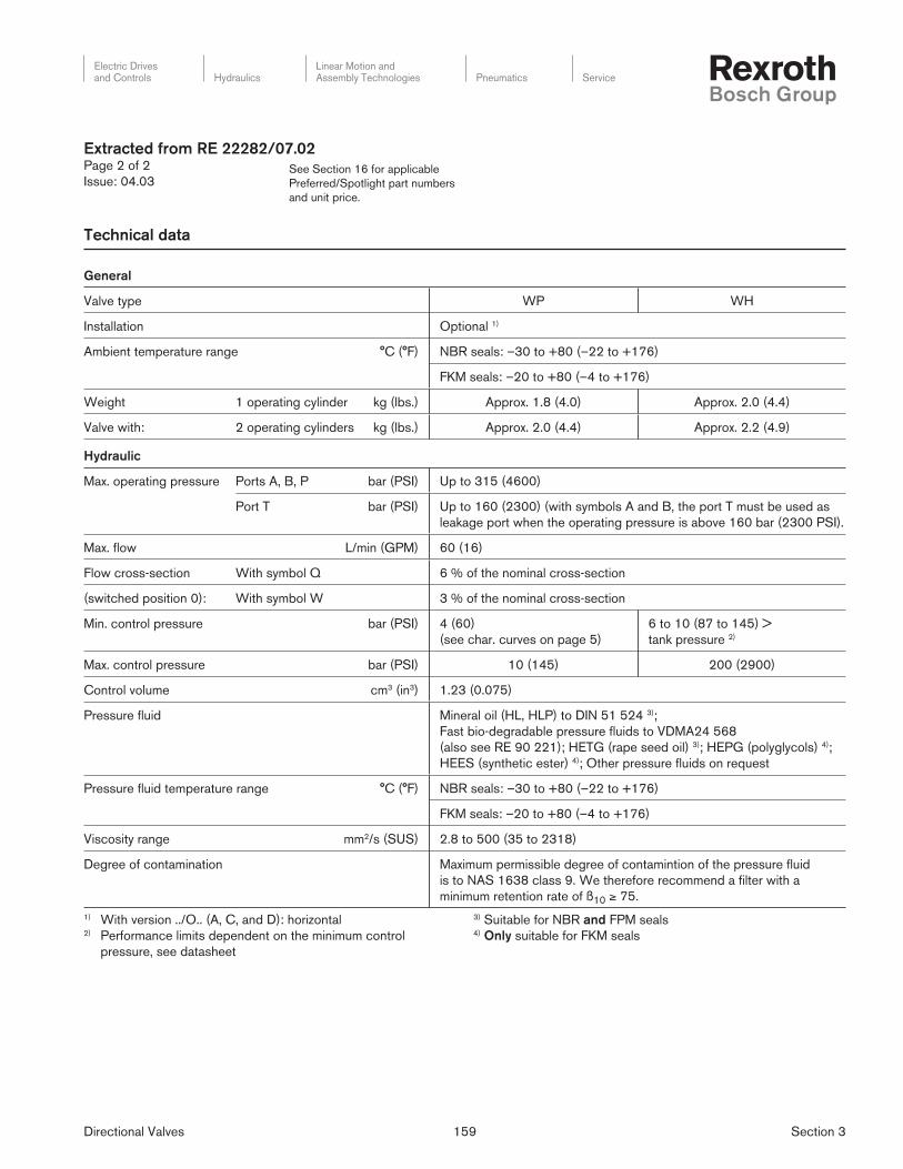
Technical data
General
Valve type WP WH
Installation Optional 1)
Ambient temperature range °C (°F) NBR seals: –30 to +80 (–22 to +176)
FKM seals: –20 to +80 (–4 to +176)
Weight 1 operating cylinder kg (lbs.) Approx. 1.8 (4.0) Approx. 2.0 (4.4)
Valve with: 2 operating cylinders kg (lbs.) Approx. 2.0 (4.4) Approx. 2.2 (4.9)
Hydraulic
Max. operating pressure Ports A, B, P bar (PSI) Up to 315 (4600)
Port T bar (PSI) Up to 160 (2300) (with symbols A and B, the port T must be used as
leakage port when the operating pressure is above 160 bar (2300 PSI).
Max. fl ow L/min (GPM) 60 (16)
Flow cross-section With symbol Q 6 % of the nominal cross-section
(switched position 0): With symbol W 3 % of the nominal cross-section
Min. control pressure bar (PSI) 4 (60)
(see char. curves on page 5)
6 to 10 (87 to 145) >
tank pressure 2)
Max. control pressure bar (PSI) 10 (145) 200 (2900)
Control volume cm3 (in3) 1.23 (0.075)
Pressure fl uid Mineral oil (HL, HLP) to DIN 51 524 3);
Fast bio-degradable pressure fl uids to VDMA24 568
(also see RE 90 221); HETG (rape seed oil) 3); HEPG (polyglycols) 4);
HEES (synthetic ester) 4); Other pressure fl uids on request
Pressure fl uid temperature range °C (°F) NBR seals: –30 to +80 (–22 to +176)
FKM seals: –20 to +80 (–4 to +176)
Viscosity range mm2/s (SUS) 2.8 to 500 (35 to 2318)
Degree of contamination Maximum permissible degree of contamintion of the pressure fl uid
is to NAS 1638 class 9. We therefore recommend a fi lter with a
minimum retention rate of ß10 ≥ 75.
1) With version ../O.. (A, C, and D): horizontal2) Performance limits dependent on the minimum control
pressure, see datasheet
3) Suitable for NBR and FPM seals4) Only suitable for FKM seals
Extracted from RE 22282/07.02Page 2 of 2
Issue: 04.03
Directional Valves 160 Section 3
Electric Drivesand Controls Hydraulics
Linear Motion andAssembly Technologies Pneumatics Service
See Section 16 for applicable
Preferred/Spotlight part numbers
and unit price.
Ordering code
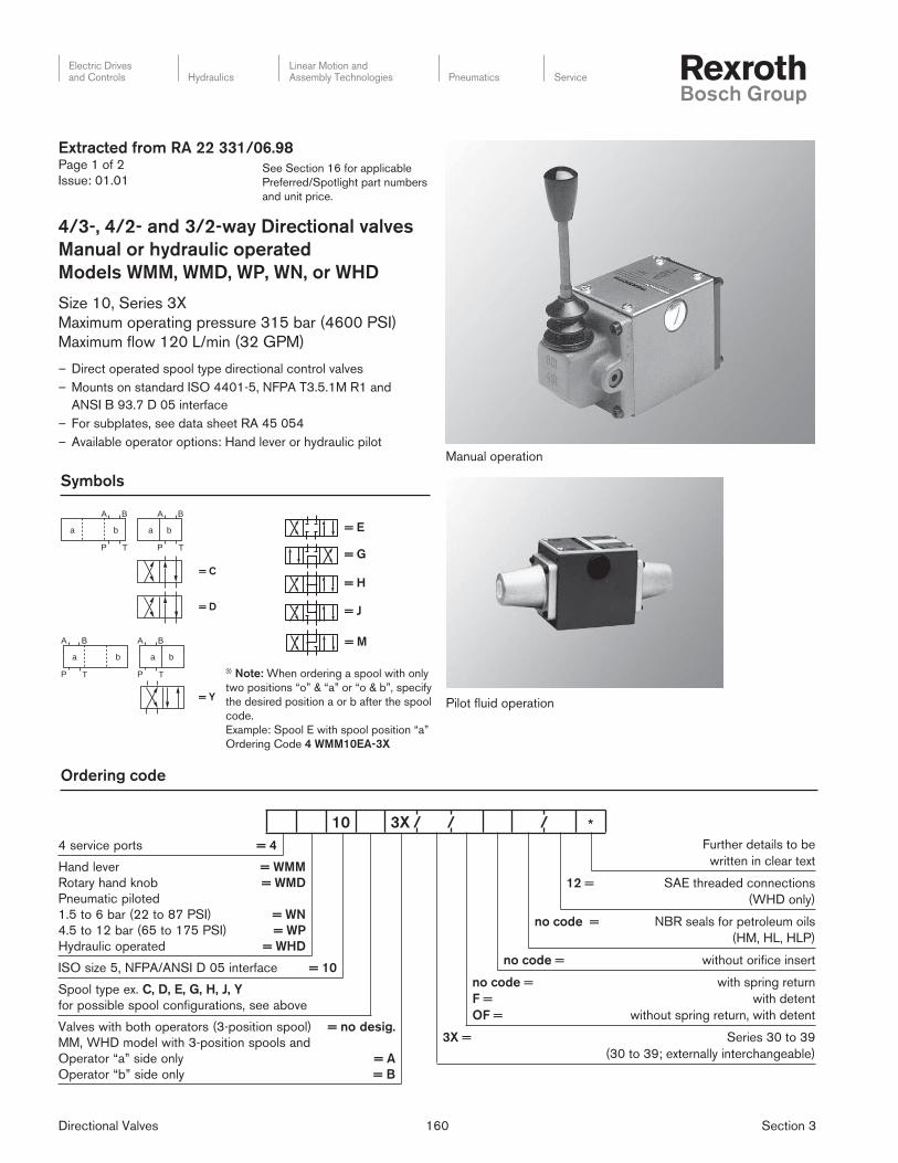
Extracted from RA 22 331/06.98Page 1 of 2
Issue: 01.01
4/3-, 4/2- and 3/2-way Directional valves
Manual or hydraulic operated
Models WMM, WMD, WP, WN, or WHD
Size 10, Series 3X
Maximum operating pressure 315 bar (4600 PSI)
Maximum fl ow 120 L/min (32 GPM)
– Direct operated spool type directional control valves
– Mounts on standard ISO 4401-5, NFPA T3.5.1M R1 and
ANSI B 93.7 D 05 interface
– For subplates, see data sheet RA 45 054
– Available operator options: Hand lever or hydraulic pilot Manual operation
Pilot fl uid operation
Further details to be
written in clear text
12 = SAE threaded connections
(WHD only)
no code = NBR seals for petroleum oils
(HM, HL, HLP)
no code = without orifi ce insert
no code =
F =
OF =
with spring return
with detent
without spring return, with detent
3X = Series 30 to 39
(30 to 39; externally interchangeable)
4 service ports = 4
Hand lever
Rotary hand knob
Pneumatic piloted
1.5 to 6 bar (22 to 87 PSI)
4.5 to 12 bar (65 to 175 PSI)
Hydraulic operated
= WMM
= WMD
= WN
= WP
= WHD
ISO size 5, NFPA/ANSI D 05 interface = 10
Spool type ex. C, D, E, G, H, J, Y
for possible spool configurations, see above
Valves with both operators (3-position spool)
MM, WHD model with 3-position spools and
Operator “a” side only
Operator “b” side only
= no desig.
= A
= B
Symbols
= M
= E
= G
= H
= J
= C
= D
a b
TP
A B
a b
TP
A B
= Y
T T
a b
P
A B
a b
P
A B
3) Note: When ordering a spool with only
two positions “o” & “a” or “o & b”, specify
the desired position a or b after the spool
code.
Example: Spool E with spool position “a”
Ordering Code 4 WMM10EA-3X
10 3X / / / *

Directional Valves 161 Section 3
Electric Drivesand Controls Hydraulics
Linear Motion andAssembly Technologies Pneumatics Service
See Section 16 for applicable
Preferred/Spotlight part numbers
and unit price.
Hydraulic
Maximum operating pressure Ports A, B, P bar (PSI) 315 (4600)
Port T bar (PSI) 160 (2320) (For spool types A and B, port T must be use a drain port,
if the operating pressure exceeds 160 bar (2320 PSI)
Maximum fl ow L/min (GPM 120 (32)
Hydraulic fl uids Petroleum oils (HM, HL, HLP)
Phosphate ester fl uids (HFD-R)
Fluid temperature range °C (°F) NBR seals: –30 to +80 (–22 to +176)
FPM seals: –20 to +80 (–4 to +176)
Viscosity range mm2/s (SUS) 2.8 to 500 (35 to 2320)
Maximum degree of fl uid contamination Class 18/15 according to ISO 4406. Therefore, we recommend
a fi lter with a retention rate of ß10 ≥ 75.
Technical data
Extracted from RA 22 331/06.98Page 2 of 2
Issue: 01.01
Directional Valves 162 Section 3
Electric Drivesand Controls Hydraulics
Linear Motion andAssembly Technologies Pneumatics Service
See Section 16 for applicable
Preferred/Spotlight part numbers
and unit price.
Ordering code
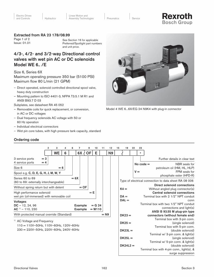
Model 4 WE 6...6X/EG 24 N9K4 with plug-in connector
Further details in clear text
No code =
V =
NBR seals for
petroleum oil (HM, HL, HLP)
FPM seals for
phosphate ester (HFD-R)
Type of electrical connection to data sheet RA 08 006
K4 =
DA =
DAL =
DK23 =
DK25 =
DK23L =
DK25L =
DK24L2 =
Direct solenoid connections
Without angled plug connector(s)
Central solenoid connections
Terminal box with 2 1/2" NPT conduit
conn
Terminal box with two 1/2" NPT conduit
connections and light(s)
ANSI B 93.55 M plug-pin type
connectors (without female end)
Terminal box with 3-pin conn.
(single solenoid)
Terminal box with 5-pin conn.
(double solenoid)
Terminal w/ 3-pin conn. & light(s)
(single solenoid)
Terminal w/ 5-pin conn. & light(s)
(double solenoid)
Terminal box with 4-pin conn., light(s), &
surge suppression
3 service ports
4 service ports
= 3
= 4
Size 6 = 6
Spool e.g. C, D, E, G, H, J, M, W, Y
Series 60 to 69
(60 to 69: externally interchangeable)
= 6X
Without spring return but with detent = OF
High performance solenoid
wet pin (oil-immersed) with removable coil
= E
Voltages
DC – 12, 24, 96
AC 1) – 110, 230
Example
Example
= G 24
= W110
With protected manual override (Standard) = N9
Extracted from RA 23 178/08.99Page 1 of 2
Issue: 01.01
4/3-, 4/2- and 3/2-way Directional control
valves with wet pin AC or DC solenoids
Model WE 6.. /E
Size 6, Series 6X
Maximum operating pressure 350 bar (5100 PSI)
Maximum fl ow 80 L/min (21 GPM)
– Direct operated, solenoid controlled directional spool valve,
heavy duty construction
– Mounting pattern to ISO 4401-3, NFPA T3.5.1 M R1 and
ANSI B93.7 D 03
Subplates, see datasheet RA 45 052
– Removable coils for quick replacement, or conversion,
in AC or DC voltages
– Dual frequency solenoids AC voltage with 50 or
60 Hz operation
– Individual electrical connectors
– Wet pin core tubes, with high pressure tank capacity, standard
1) AC Voltage and Frequency
110 = 110V–50Hz, 110V–60Hz, 120V–60Hz
230 = 220V–50Hz, 220V–60Hz, 240V–60Hz
2 3 4 6 7 9 10 11 12 15 19 22 23
WE 6 6X / OF E N9 / *
Directional Valves 163 Section 3
Electric Drivesand Controls Hydraulics
Linear Motion andAssembly Technologies Pneumatics Service
See Section 16 for applicable
Preferred/Spotlight part numbers
and unit price.
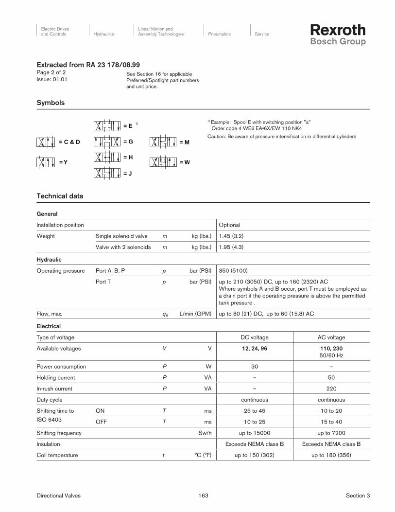
1) Example: Spool E with switching position "a"
Order code 4 WE6 EA•6X/EW 110 NK4
Caution: Be aware of pressure intensifi cation in differential cylinders
Symbols
= C & D
= Y
= G
= H
= J
= E
= M
= W
Technical data
General
Installation position Optional
Weight Single solenoid valve m kg (lbs.) 1.45 (3.2)
Valve with 2 solenoids m kg (lbs.) 1.95 (4.3)
Hydraulic
Operating pressure Port A, B, P p bar (PSI) 350 (5100)
Port T p bar (PSI) up to 210 (3050) DC, up to 160 (2320) AC
Where symbols A and B occur, port T must be employed as
a drain port if the operating pressure is above the permitted
tank pressure .
Flow, max. qV L/min (GPM) up to 80 (21) DC, up to 60 (15.8) AC
Electrical
Type of voltage DC voltage AC voltage
Available voltages V V 12, 24, 96 110, 230
50/60 Hz
Power consumption P W 30 –
Holding current P VA – 50
In-rush current P VA – 220
Duty cycle continuous continuous
Shifting time to
ISO 6403
ON T ms 25 to 45 10 to 20
OFF T ms 10 to 25 15 to 40
Shifting frequency Sw/h up to 15000 up to 7200
Insulation Exceeds NEMA class B Exceeds NEMA class B
Coil temperature t °C (°F) up to 150 (302) up to 180 (356)
Extracted from RA 23 178/08.99Page 2 of 2
Issue: 01.01
1)
Directional Valves 164 Section 3
Electric Drivesand Controls Hydraulics
Linear Motion andAssembly Technologies Pneumatics Service
See Section 16 for applicable
Preferred/Spotlight part numbers
and unit price.
General
Installation optional
Weight Central connection Individual connection
Valve with 1 solenoid kg (lbs.) DC 4.4 (9.7), AC 3.6 (7.93) DC 4.3 (9.48), AC 3.5 (7.71)
Valve with 2 solenoids kg (lbs.) DC 6.0 (13.2), AC 4.4 (9.7) DC 5.9 (13), AC 4.3 (9.48)
Hydraulic data
Max. operating pressure Ports A, B, P bar (PSI) 315 (4600)
Port T bar (PSI) DC 210 (3050), AC 160 (2320). For symbols A and B,
Port T must be used as a drain line if the operating pressure is
higher than the permissible tank pressure.
Max. fl ow L/min (GPM) 120 (32)
Electrical data
Voltage model DC AC
Available voltages V 12, 24, 96 110, 230
50/60 Hz
Voltage tolerance (nominal voltage) % ±10
Power consumption W 35 –
Holding power VA – 90
Inrush current VA – 550
Duty continuous
Switching time to ISO 6403 ON ms 45 to 60 15 to 25
OFF ms 20 to 30 20 to 30
Switching frequency cycles/h 15,000 7,200
Protection to DIN 40 050 IP 65
Insulation class VDE 0580 F H
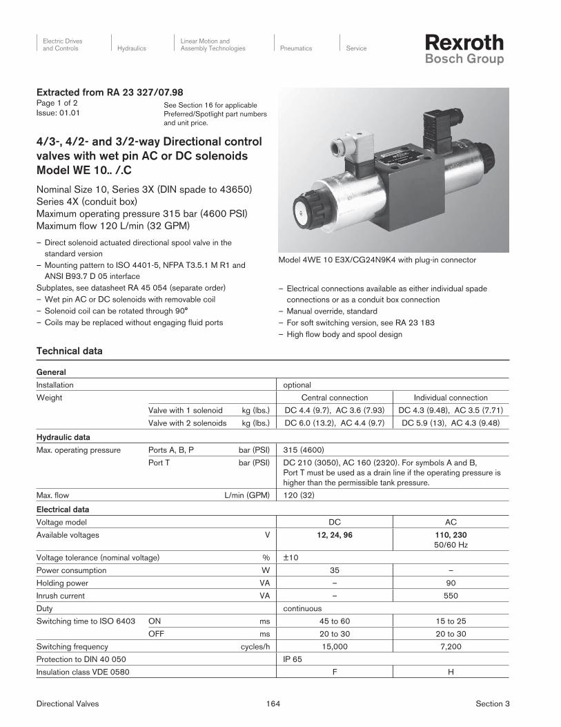
Model 4WE 10 E3X/CG24N9K4 with plug-in connector
Extracted from RA 23 327/07.98Page 1 of 2
Issue: 01.01
4/3-, 4/2- and 3/2-way Directional control
valves with wet pin AC or DC solenoids
Model WE 10.. /.C
Nominal Size 10, Series 3X (DIN spade to 43650)
Series 4X (conduit box)
Maximum operating pressure 315 bar (4600 PSI)
Maximum fl ow 120 L/min (32 GPM)
– Direct so le noid actuated directional spool valve in the
standard version
– Mounting pattern to ISO 4401-5, NFPA T3.5.1 M R1 and
ANSI B93.7 D 05 interface
Subplates, see datasheet RA 45 054 (separate order)
– Wet pin AC or DC solenoids with removable coil
– Solenoid coil can be rotated through 90°
– Coils may be replaced without engaging fl uid ports
Technical data
– Electrical connections available as either individual spade
connections or as a conduit box connection
– Manual override, standard
– For soft switching version, see RA 23 183
– High fl ow body and spool design
Directional Valves 165 Section 3
Electric Drivesand Controls Hydraulics
Linear Motion andAssembly Technologies Pneumatics Service
See Section 16 for applicable
Preferred/Spotlight part numbers
and unit price.
3 service ports4 service ports
= 3 = 4
Directional control valve, electrically operated
ISO Size 5, NFPA/ANSI D 05 interface = 10
Spool symbol e.g. E, G, H, J, M, W etc.
Series 30 to 39 – spade connection(30 to 39: externally interchangeable)Series 40 to 49 – conduit box connection(40 to 49: externally interchangeable)
= 3X
= 4X
With spring returnWithout spring return, with detent
= No code
= OF
Wet pin solenoid (oil immersed) with removable coil = C
Voltages
DC – 12, 24, 96AC1) – 110, 220
Example
Example
= G 24
= W110
With manual override (standard) = N9
Central solenoid connections
1/2" NPT conduit connector in conduit box1/2" NPT conduit connector in conduit box with light(s)
ANSI B 93.55 M plug-in type connections (without female end)Terminal box with 3-pin connector (single solenoid)Terminal box with 5-pin connector (double solenoid)Terminal box with 3-pin connector and lights (single solenoid)Terminal box with 5-pin connector and lights (double solenoid)Terminal box with 4-pin connector, lights, and surge suppression
Individual solenoid plug connections
Without plug in connector(s)
= DA
= DAL
= DK23
= DK25
= DK23L
= DK25L
= DK24L2
= K4
NBR sealsFPM seals
Attention! The compatibility of the seals and fl uid must be taken into account!
= No code
= V
Further details in clear text
Ordering code
Extracted from RA 23 327/07.98Page 2 of 2
Issue: 01.01
1) AC Voltage and Frequency
110 = 110V–50Hz, 110V–60Hz, 120V–60Hz
230 = 220V–50Hz, 220V–60Hz, 240V–60Hz
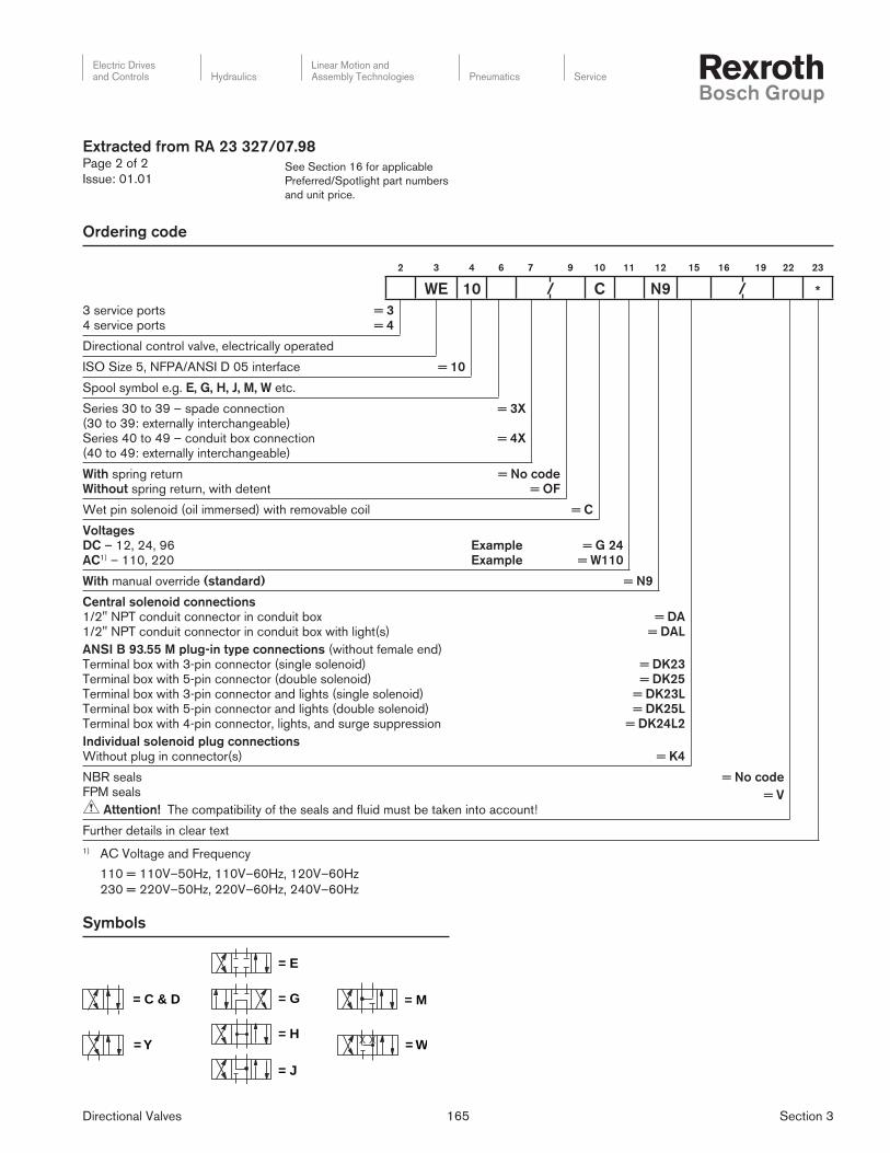
Symbols
= C & D
= Y
= G
= H
= J
= E
= M
= W
2 3 4 6 7 9 10 11 12 15 16 19 22 23
WE 10 / C N9 / *
Directional Valves 166 Section 3
Electric Drivesand Controls Hydraulics
Linear Motion andAssembly Technologies Pneumatics Service
See Section 16 for applicable
Preferred/Spotlight part numbers
and unit price.
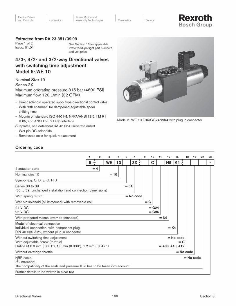
Extracted from RA 23 351/09.99Page 1 of 2
Issue: 01.01
4/3-, 4/2- and 3/2-way Directional valves
with switching time adjustment
Model 5-.WE 10
Nominal Size 10
Series 3X
Maximum operating pressure 315 bar (4600 PSI)
Maximum fl ow 120 L/min (32 GPM)
– Direct solenoid operated spool type directional control valve
– With “5th chamber” for dampened adjustable spool
shifting time
– Mounts on standard ISO 4401-5, NFPA/ANSI T3.5.1 M R1
D 05, and ANSI B93.7 D 05 interface
Subplates, see datasheet RA 45 054 (separate order)
– Wet pin DC solenoids
– Removable coils for quick replacement
Model 5-.WE 10 E3X/CG24N9K4 with plug-in connector
Ordering code
4 actuator ports = 4
Nominal size 10 = 10
Symbol e.g. C, D, E, G, H, J
Series 30 to 39
(30 to 39: unchanged installation and connection dimensions)
= 3X
With spring return = No code
Wet pin solenoid (oil immersed) with removable coil = C
24 V DC
96 V DC
= G24
= G96
With protected manual override (standard) = N9
Model of electrical connection
Individual connection; with component plug
DIN 43 650-AM2, without plug-in connector
= K4
Without switching time adjustment
With adjustable screw (throttle)
Orifice Ø 0.8 mm (0.031”), 1.0 mm (0.039”), 1.2 mm (0.047” )
= No code
= C
= A08, A10, A12
Without cartridge throttle = No code
NBR seals
Attention!
The compatibility of the seals and pressure fluid has to be taken into account!
= No code
Further details to be written in clear text
1 2 3 4 6 7 9 10 11 12 15 18 19 22 23
5 – WE 10 3X / C N9 K4 / *
Directional Valves 167 Section 3
Electric Drivesand Controls Hydraulics
Linear Motion andAssembly Technologies Pneumatics Service
See Section 16 for applicable
Preferred/Spotlight part numbers
and unit price.
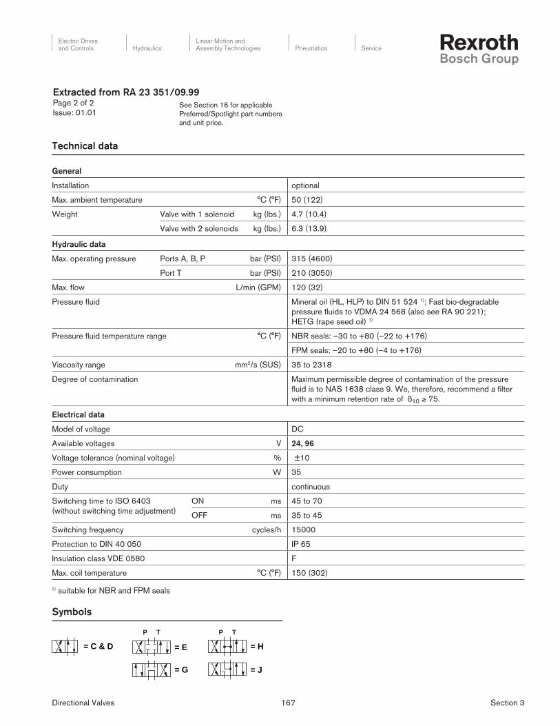
General
Installation optional
Max. ambient temperature °C (°F) 50 (122)
Weight Valve with 1 solenoid kg (lbs.) 4.7 (10.4)
Valve with 2 solenoids kg (lbs.) 6.3 (13.9)
Hydraulic data
Max. operating pressure Ports A, B, P bar (PSI) 315 (4600)
Port T bar (PSI) 210 (3050)
Max. fl ow L/min (GPM) 120 (32)
Pressure fl uid Mineral oil (HL, HLP) to DIN 51 524 1); Fast bio-degradable
pressure fl uids to VDMA 24 568 (also see RA 90 221);
HETG (rape seed oil) 1)
Pressure fl uid temperature range °C (°F) NBR seals: –30 to +80 (–22 to +176)
FPM seals: –20 to +80 (–4 to +176)
Viscosity range mm2/s (SUS) 35 to 2318
Degree of contamination Maximum permissible degree of contamination of the pressure
fl u id is to NAS 1638 class 9. We, therefore, recommend a fi lter
with a minimum retention rate of ß10 ≥ 75.
Electrical data
Model of voltage DC
Available voltages V 24, 96
Voltage tolerance (nominal voltage) % ±10
Power consumption W 35
Duty continuous
Switching time to ISO 6403
(without switching time adjustment)
ON ms 45 to 70
OFF ms 35 to 45
Switching frequency cycles/h 15000
Protection to DIN 40 050 IP 65
Insulation class VDE 0580 F
Max. coil temperature °C (°F) 150 (302)
1) suitable for NBR and FPM seals
Extracted from RA 23 351/09.99Page 2 of 2
Issue: 01.01
Technical data
TP TP
= C & D
= G
= H
= J
= E
Symbols
Directional Valves 168 Section 3
Electric Drivesand Controls Hydraulics
Linear Motion andAssembly Technologies Pneumatics Service
See Section 16 for applicable
Preferred/Spotlight part numbers
and unit price.
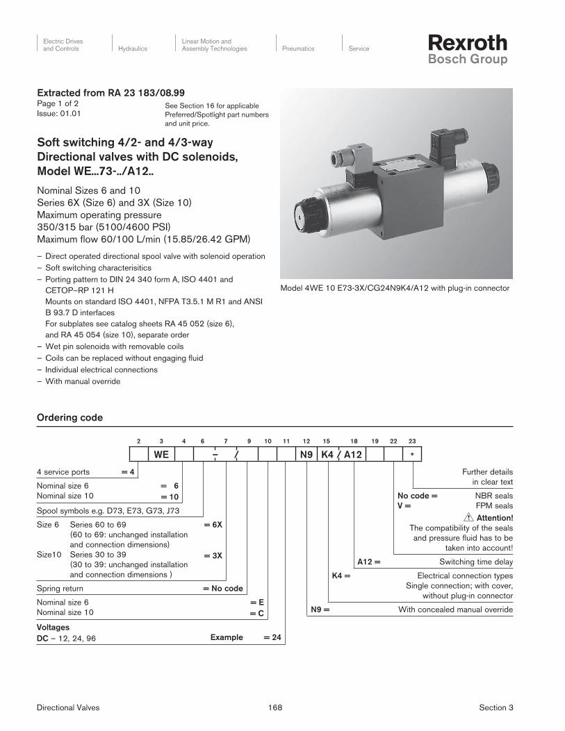
Model 4WE 10 E73-3X/CG24N9K4/A12 with plug-in con nec tor
Ordering code
Further details
in clear text
No code =
V =
NBR seals
FPM seals
Attention!
The compatibility of the seals
and pressure fluid has to be
taken into account!
A12 = Switching time delay
K4 = Electrical connection types
Single connection; with cover,
without plug-in connector
N9 = With concealed manual override
4 service ports = 4
Nominal size 6
Nominal size 10
= 6
= 10
Spool symbols e.g. D73, E73, G73, J73
Size 6 Series 60 to 69
(60 to 69: unchanged installation
and connection dimensions)
Size10 Series 30 to 39
(30 to 39: unchanged installation
and connection dimensions )
= 6X
= 3X
Spring return = No code
Nominal size 6
Nominal size 10
= E
= C
Voltages
DC – 12, 24, 96 Example = 24
Extracted from RA 23 183/08.99Page 1 of 2
Issue: 01.01
Soft switching 4/2- and 4/3-way
Directional valves with DC solenoids,
Model WE...73-../A12..
Nominal Sizes 6 and 10
Series 6X (Size 6) and 3X (Size 10)
Maximum op er at ing pressure
350/315 bar (5100/4600 PSI)
Maximum fl ow 60/100 L/min (15.85/26.42 GPM)
– Direct operated directional spool valve with solenoid operation
– Soft switching characterisitics
– Porting pattern to DIN 24 340 form A, ISO 4401 and
CETOP–RP 121 H
Mounts on standard ISO 4401, NFPA T3.5.1 M R1 and ANSI
B 93.7 D interfaces
For subplates see catalog sheets RA 45 052 (size 6),
and RA 45 054 (size 10), separate order
– Wet pin solenoids with removable coils
– Coils can be replaced without engaging fl uid
– Individual electrical connections
– With manual override
2 3 4 6 7 9 10 11 12 15 18 19 22 23
WE – / N9 K4 / A12 *
Directional Valves 169 Section 3
Electric Drivesand Controls Hydraulics
Linear Motion andAssembly Technologies Pneumatics Service
See Section 16 for applicable
Preferred/Spotlight part numbers
and unit price.
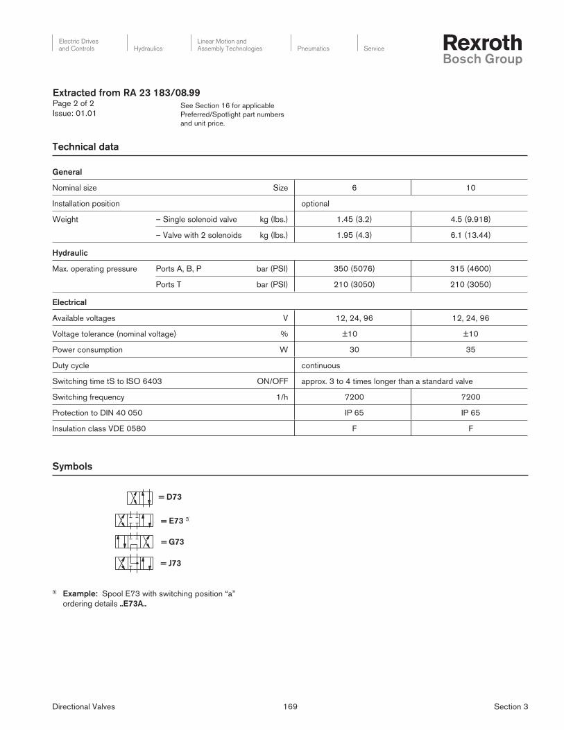
= E73 3)
= G73
= J73
= D73
Symbols
3) Example: Spool E73 with switching position “a”
ordering details ..E73A..
General
Nominal size Size 6 10
Installation position optional
Weight – Single solenoid valve kg (lbs.) 1.45 (3.2) 4.5 (9.918)
– Valve with 2 solenoids kg (lbs.) 1.95 (4.3) 6.1 (13.44)
Hydraulic
Max. operating pressure Ports A, B, P bar (PSI) 350 (5076) 315 (4600)
Ports T bar (PSI) 210 (3050) 210 (3050)
Electrical
Available voltages V 12, 24, 96 12, 24, 96
Voltage tolerance (nominal voltage) % ±10 ±10
Power consumption W 30 35
Duty cycle continuous
Switching time tS to ISO 6403 ON/OFF approx. 3 to 4 times longer than a standard valve
Switching frequency 1/h 7200 7200
Protection to DIN 40 050 IP 65 IP 65
Insulation class VDE 0580 F F
Technical data
Extracted from RA 23 183/08.99Page 2 of 2
Issue: 01.01

Directional Valves 170 Section 3
Electric Drivesand Controls Hydraulics
Linear Motion andAssembly Technologies Pneumatics Service
See Section 16 for applicable
Preferred/Spotlight part numbers
and unit price.
Symbols (to ISO 1219)
4WEH.. EA.xx/... = 2-position main valve with single solenoid pilot
4WEH.. HD.xx/OF... = 2-position main valve with detented pilot,
main stage hydraulically offset
4WEH.. D.xx/OF... = 2-position main valve with detented pilot,
main stage spring offset
4WEH.. D.xx/... = 2-position main valve with single solenoid pilot,
main stage spring offset
Model 4WEH 22 E 7X/..6EG..N9..DA.. with plug-in con nec tor
Technical data
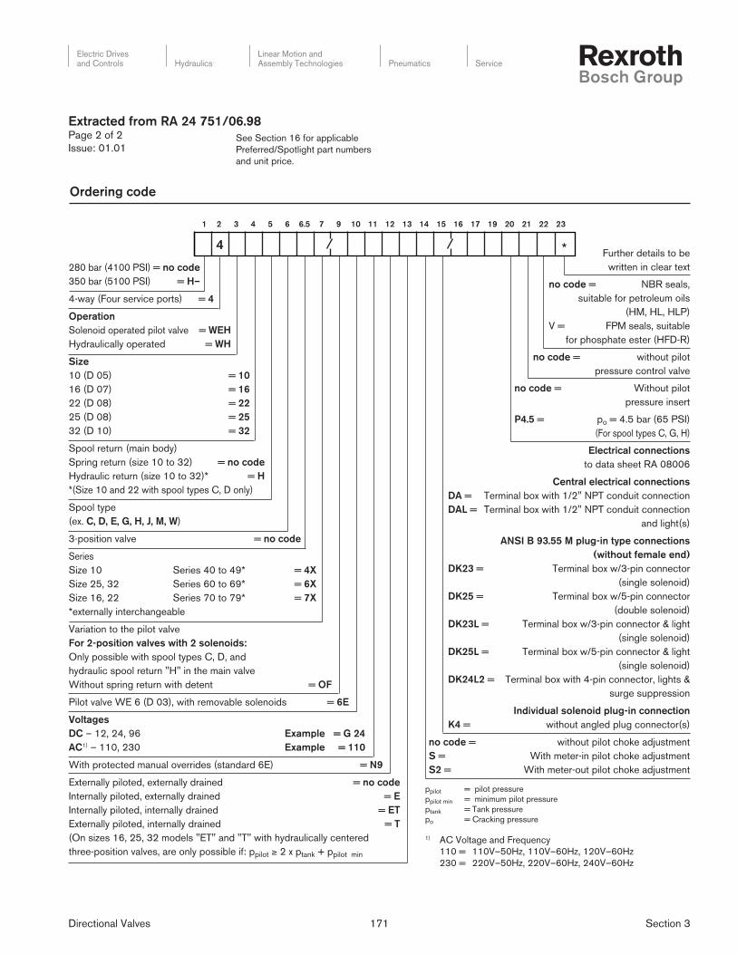
Extracted from RA 24 751/06.98Page 1 of 2
Issue: 01.01
4/2- and 4/3-way Directional valves,
Pilot operated, Model 4 WEH…
Externally pilot operated, Model 4 WH …
Sizes 10 to 32, Series 4X, 6X, 7X
Maximum pressure up to 350 bar (5100 PSI)
Maximum volume up to 1100 L/min (290 GPM)
– Solenoid pilot operated directional valves (WEH)
– Hydraulic pilot operated directional valves (WH)
– Mounts on standard ISO 4401-5, 7, 8, or 10, NFPA T 3.5.1 M
R1 and ANSI B 93.7 D 05, D 07, D 08, or D10 interfaces
– For subplates, see data sheets RA 45 045 ... RA 45 060, may
be ordered separately
– 3-position spring centered (sizes 10 to 32)
– 3-position spring or hydraulic centering (sizes 16, 25 and 32)
– 2-position hydraulic or spring offset (sizes 10 to 32)
– Wet pin AC or DC solenoids as required
– Manual overrides standard (WEH)
– Individual solenoid plug-in connectors or central wiring box,
see datasheet RA 08 006
– Optional meter-in or meter-out pilot choke option
– "P" port pilot pressure insert (sizes 16 to 32), for open center
spools
= M
= E
= G
= H
= J
= D/C
= Q
= W
Sizes (ordering code) 10 16 22 25 32
Operating pressure, max.
– Port P, A, B
Model 4WEH bar (PSI) 280 (4060) 280 (4060) 280 (4060) – 280 (4060)
Model H-4WEH bar (PSI) 350 (5100) 350 (5100) 350 (5100) 350 (5100) 350 (5100)
– Port T Pilot oil drain Y external bar (PSI) 315 (4600) 250 (3625) 250 (3625) 250 (3625) 250 (3625)
Pilot oil drain Y internal bar (PSI) 3046 DC
bar (PSI) 2321 AC
– Port Y Pilot oil drain external: bar (PSI) 3046 DC, 2321 AC
with version 4WH bar (PSI) 250 (3625) 250 (3625) 210 (3050) 250 (3625) 250 (3625)
Pilot pressure, max. bar (PSI) 250 (3625) 250 (3625) 210 (3050) 250 (3625) 250 (3625)(With higher pilot pressures, a pressure reducing valve is required.)
Pilot pressure, min.– Pilot oil supply X external, pilot oil supply X internal
10 (145)
H-4W..
14 (205)
4W..
12.5 (180)
10.5 (150) 13 (190) 8.5 (125)
(not with spools: C, G, H)3-position valve, spring-centered bar (PSI)
3-position valve, pressure-centered bar (PSI) – 14 (205) – 18 (260) 8.5 (125)
2-position valve, with spring offsetbar (PSI) 10 (145) 14 (205)
14 (205)
11 (160)
13 (190) 10 (145)
2-position valve, with hydraulic offset bar (PSI) 7 (100) 14 (205) 8 (115) 8 (115) 5 (72)
– Internally piloted (with spools C, F, G, H, P, T, V, Z, S) bar (PSI) 4.5 (65) 4.5 (65) 4.5 (65) 4.5 (65) 4.5 (65)
Directional Valves 171 Section 3
Electric Drivesand Controls Hydraulics
Linear Motion andAssembly Technologies Pneumatics Service
See Section 16 for applicable
Preferred/Spotlight part numbers
and unit price.
280 bar (4100 PSI) = no code
350 bar (5100 PSI) = H–
4-way (Four service ports) = 4
Operation
Solenoid operated pilot valve = WEH
Hydraulically operated = WH
Size
10 (D 05) = 10
16 (D 07) = 16
22 (D 08) = 22
25 (D 08) = 25
32 (D 10) = 32
Spool return (main body)
Spring return (size 10 to 32) = no code
Hydraulic return (size 10 to 32)* = H
*(Size 10 and 22 with spool types C, D only)
Spool type
(ex. C, D, E, G, H, J, M, W)
3-position valve = no code
Series
Size 10 Series 40 to 49* = 4X
Size 25, 32 Series 60 to 69* = 6X
Size 16, 22 Series 70 to 79* = 7X
*externally interchangeable
Variation to the pilot valve
For 2-position valves with 2 solenoids:
Only possible with spool types C, D, and
hydraulic spool return "H" in the main valve
Without spring return with detent = OF
Pilot valve WE 6 (D 03), with removable solenoids = 6E
Voltages
DC – 12, 24, 96 Example = G 24
AC1) – 110, 230 Example = 110
With protected manual overrides (standard 6E) = N9
Externally piloted, externally drained = no code
Internally piloted, externally drained = E
Internally piloted, internally drained = ET
Externally piloted, internally drained = T
(On sizes 16, 25, 32 models "ET" and "T" with hydraulically centered
three-position valves, are only possible if: ppilot ≥ 2 x ptank + ppilot min
Further details to be
written in clear text
no code = NBR seals,
suitable for petroleum oils
(HM, HL, HLP)
V = FPM seals, suitable
for phosphate ester (HFD-R)
no code = without pilot
pressure control valve
no code = Without pilot
pressure insert
P4.5 = po = 4.5 bar (65 PSI)
(For spool types C, G, H)
Electrical connections
to data sheet RA 08006
Central electrical connections
DA = Terminal box with 1/2" NPT conduit connection
DAL = Terminal box with 1/2" NPT conduit connection
and light(s)
ANSI B 93.55 M plug-in type connections
(without female end)
DK23 = Terminal box w/3-pin connector
(single solenoid)
DK25 = Terminal box w/5-pin connector
(double solenoid)
DK23L = Terminal box w/3-pin connector & light
(single solenoid)
DK25L = Terminal box w/5-pin connector & light
(single solenoid)
DK24L2 = Terminal box with 4-pin connector, lights &
surge suppression
Individual solenoid plug-in connection
K4 = without angled plug connector(s)
no code = without pilot choke adjustment
S = With meter-in pilot choke adjustment
S2 = With meter-out pilot choke adjustment
*
1 2 3 4 5 6 6.5 7 9 10 11 12 13 14 15 16 17 19 20 21 22 23
4
ppilot = pilot pressure
ppilot min = minimum pilot pressure
ptank = Tank pressure
po = Cracking pressure
Ordering code
Extracted from RA 24 751/06.98Page 2 of 2
Issue: 01.01
1) AC Voltage and Frequency
110 = 110V–50Hz, 110V–60Hz, 120V–60Hz
230 = 220V–50Hz, 220V–60Hz, 240V–60Hz
Directional Valves 172 Section 3
Electric Drivesand Controls Hydraulics
Linear Motion andAssembly Technologies Pneumatics Service
See Section 16 for applicable
Preferred/Spotlight part numbers
and unit price.
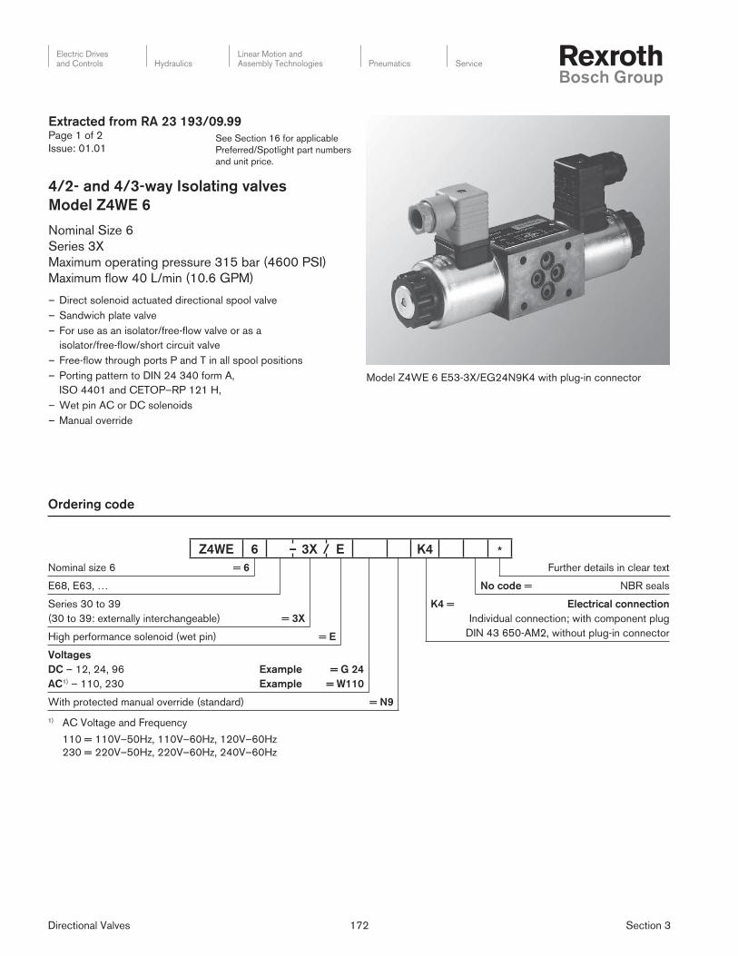
Nominal size 6 = 6
E68, E63, …
Series 30 to 39
(30 to 39: externally interchangeable) = 3X
High performance solenoid (wet pin) = E
Voltages
DC – 12, 24, 96 Example
AC1) – 110, 230 Example
= G 24
= W110
With protected manual override (standard) = N9
Further details in clear text
No code = NBR seals
K4 = Electrical connection
Individual connection; with component plug
DIN 43 650-AM2, without plug-in connector
Ordering code
Extracted from RA 23 193/09.99Page 1 of 2
Issue: 01.01
4/2- and 4/3-way Isolating valves
Model Z4WE 6
Nominal Size 6
Series 3X
Maximum operating pressure 315 bar (4600 PSI)
Maximum fl ow 40 L/min (10.6 GPM)
– Direct solenoid actuated directional spool valve
– Sandwich plate valve
– For use as an isolator/free-fl ow valve or as a
isolator/free-fl ow/short circuit valve
– Free-fl ow through ports P and T in all spool positions
– Porting pattern to DIN 24 340 form A,
ISO 4401 and CETOP–RP 121 H,
– Wet pin AC or DC solenoids
– Manual override
1) AC Voltage and Frequency
110 = 110V–50Hz, 110V–60Hz, 120V–60Hz
230 = 220V–50Hz, 220V–60Hz, 240V–60Hz
Model Z4WE 6 E53-3X/EG24N9K4 with plug-in connector
Z4WE 6 – 3X / E K4 *
Directional Valves 173 Section 3
Electric Drivesand Controls Hydraulics
Linear Motion andAssembly Technologies Pneumatics Service
See Section 16 for applicable
Preferred/Spotlight part numbers
and unit price.
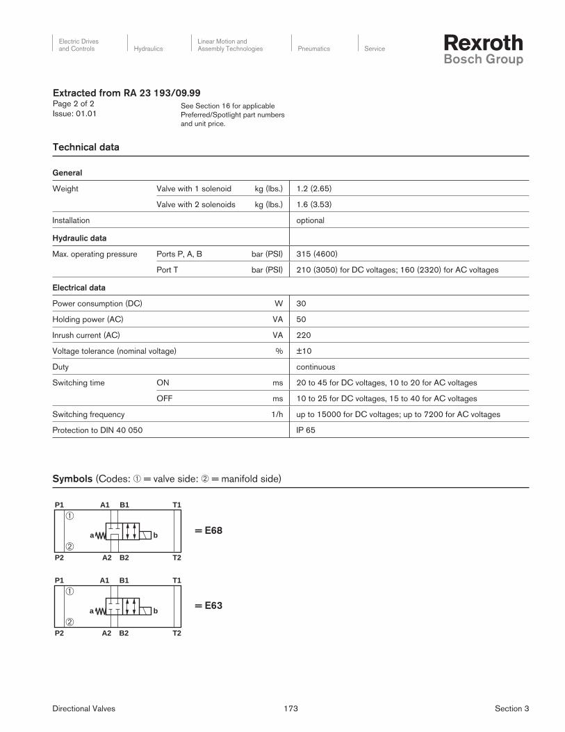
Technical data
General
Weight Valve with 1 solenoid kg (lbs.) 1.2 (2.65)
Valve with 2 solenoids kg (lbs.) 1.6 (3.53)
Installation optional
Hydraulic data
Max. operating pressure Ports P, A, B bar (PSI) 315 (4600)
Port T bar (PSI) 210 (3050) for DC voltages; 160 (2320) for AC voltages
Electrical data
Power consumption (DC) W 30
Holding power (AC) VA 50
Inrush current (AC) VA 220
Voltage tolerance (nominal voltage) % ±10
Duty continuous
Switching time ON ms 20 to 45 for DC voltages, 10 to 20 for AC voltages
OFF ms 10 to 25 for DC voltages, 15 to 40 for AC voltages
Switching frequency 1/h up to 15000 for DC voltages; up to 7200 for AC voltages
Protection to DIN 40 050 IP 65
Extracted from RA 23 193/09.99Page 2 of 2
Issue: 01.01
P1 A1 B1
P2 A2 B2
a b
T1
T2
P1 A1 B1 T1
P2 A2 B2 T2
a b
➀
➀
➁
➁
= E68
= E63
Symbols (Codes: ➀ = valve side: ➁ = manifold side)
Directional Valves 174 Section 3
Electric Drivesand Controls Hydraulics
Linear Motion andAssembly Technologies Pneumatics Service
See Section 16 for applicable
Preferred/Spotlight part numbers
and unit price.
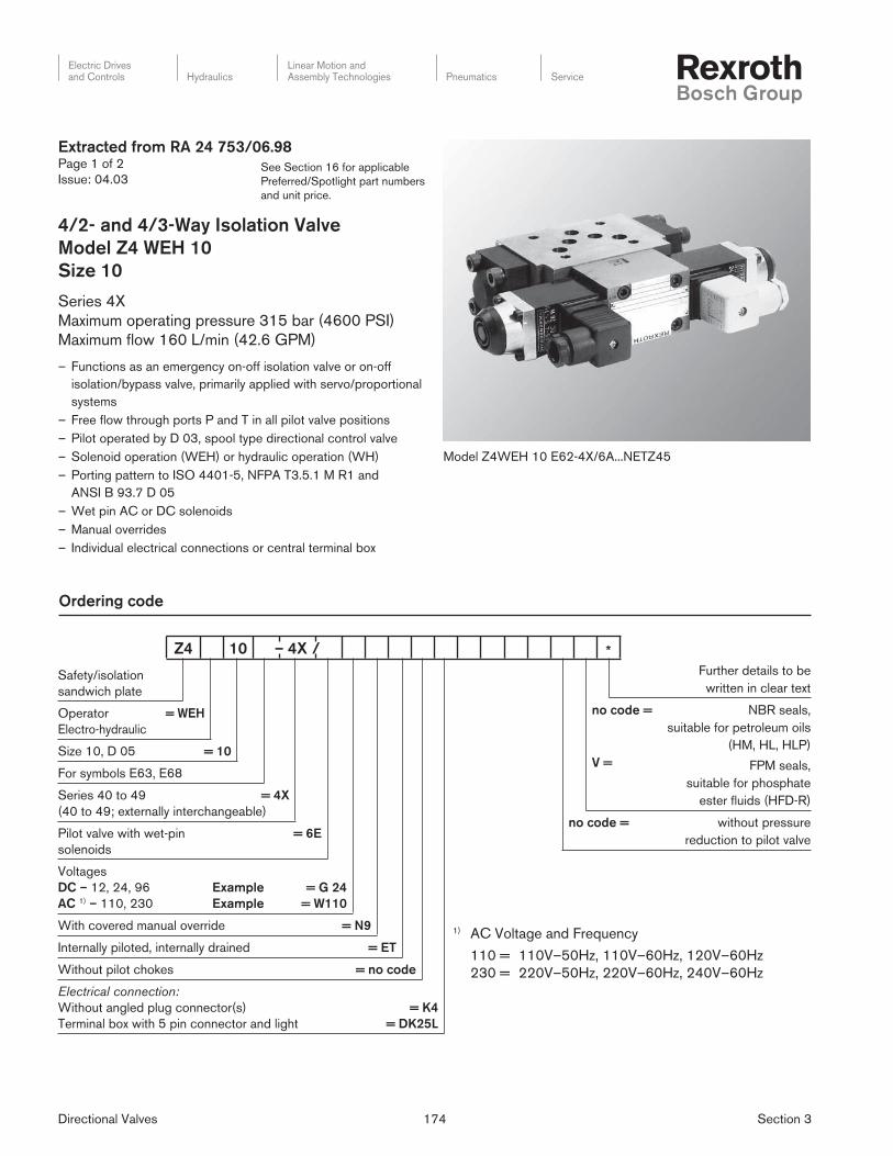
Extracted from RA 24 753/06.98Page 1 of 2
Issue: 04.03
4/2- and 4/3-Way Iso la tion Valve
Model Z4 WEH 10
Size 10
Series 4X
Maximum operating pressure 315 bar (4600 PSI)
Maximum fl ow 160 L/min (42.6 GPM)
– Functions as an emergency on-off isolation valve or on-off
isolation/bypass valve, primarily applied with servo/proportional
systems
– Free fl ow through ports P and T in all pilot valve positions
– Pilot operated by D 03, spool type directional control valve
– Solenoid operation (WEH) or hydraulic operation (WH)
– Porting pattern to ISO 4401-5, NFPA T3.5.1 M R1 and
ANSI B 93.7 D 05
– Wet pin AC or DC solenoids
– Manual overrides
– Individual electrical connections or central terminal box
Model Z4WEH 10 E62-4X/6A...NETZ45
Safety/isolation
sandwich plate
Operator
Electro-hydraulic
= WEH
Size 10, D 05 = 10
For symbols E63, E68
Series 40 to 49 = 4X
(40 to 49; externally interchangeable)
Pilot valve with wet-pin
solenoids
= 6E
Voltages
DC – 12, 24, 96
AC 1) – 110, 230
Example
Example
= G 24
= W110
With covered manual override = N9
Internally piloted, internally drained = ET
Without pilot chokes = no code
Electrical connection:
Without angled plug connector(s)
Terminal box with 5 pin connector and light
= K4
= DK25L
Further details to be
written in clear text
no code =
V =
NBR seals,
suitable for petroleum oils
(HM, HL, HLP)
FPM seals,
suitable for phosphate
ester fl uids (HFD-R)
no code = without pressure
reduction to pilot valve
Ordering code
1) AC Voltage and Frequency
110 = 110V–50Hz, 110V–60Hz, 120V–60Hz
230 = 220V–50Hz, 220V–60Hz, 240V–60Hz
Z4 10 – 4X / *
Directional Valves 175 Section 3
Electric Drivesand Controls Hydraulics
Linear Motion andAssembly Technologies Pneumatics Service
See Section 16 for applicable
Preferred/Spotlight part numbers
and unit price.
Extracted from RA 24 753/06.98Page 2 of 2
Issue: 04.03
Technical data
General
Weight (approx.)
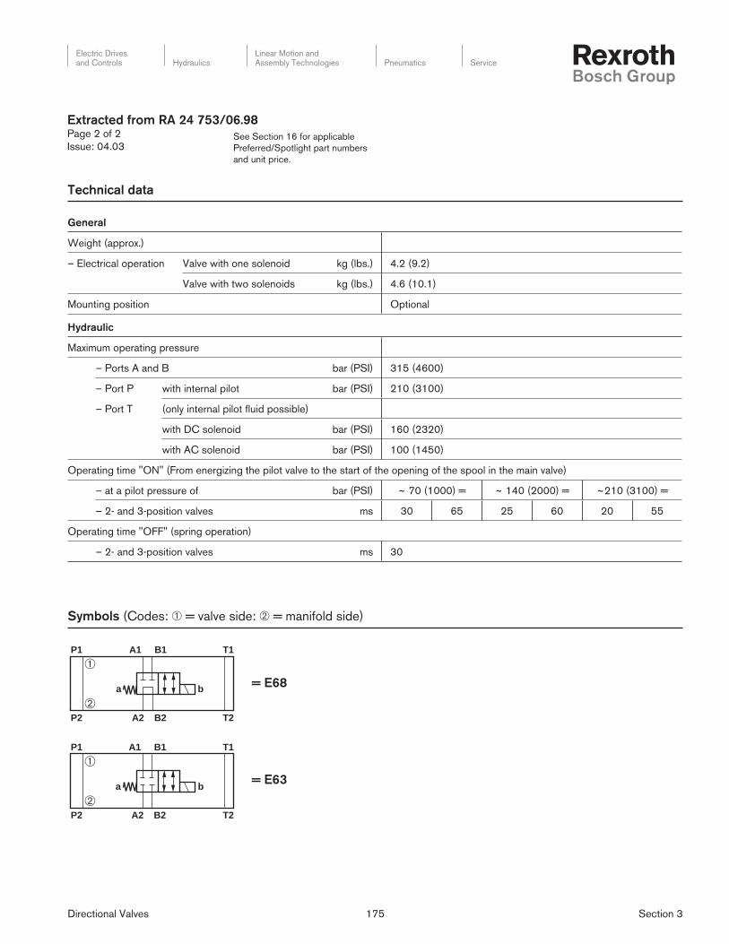
– Electrical operation Valve with one solenoid kg (lbs.) 4.2 (9.2)
Valve with two solenoids kg (lbs.) 4.6 (10.1)
Mounting position Optional
Hydraulic
Maximum operating pressure
– Ports A and B bar (PSI) 315 (4600)
– Port P with internal pilot bar (PSI) 210 (3100)
– Port T (only internal pilot fl uid possible)
with DC solenoid bar (PSI) 160 (2320)
with AC solenoid bar (PSI) 100 (1450)
Operating time "ON" (From energizing the pilot valve to the start of the opening of the spool in the main valve)
– at a pilot pressure of bar (PSI) ~ 70 (1000) = ~ 140 (2000) = ~210 (3100) =
– 2- and 3-position valves ms 30 65 25 60 20 55
Operating time "OFF" (spring operation)
– 2- and 3-position valves ms 30
P1 A1 B1
P2 A2 B2
a b
T1
T2
P1 A1 B1 T1
P2 A2 B2 T2
a b
➀
➀
➁
➁
= E68
= E63
Symbols (Codes: ➀ = valve side: ➁ = manifold side)
Directional Valves 176 Section 3
Electric Drivesand Controls Hydraulics
Linear Motion andAssembly Technologies Pneumatics Service
See Section 16 for applicable
Preferred/Spotlight part numbers
and unit price.
Ordering code
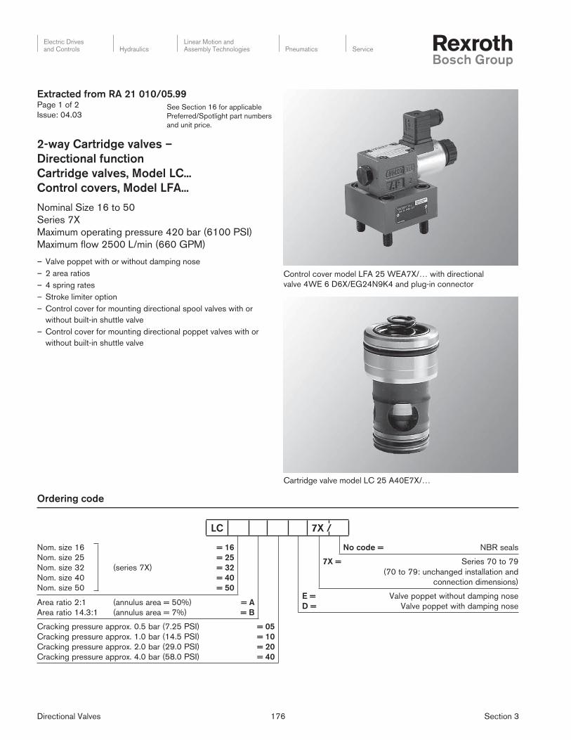
Control cover model LFA 25 WEA7X/… with directional
valve 4WE 6 D6X/EG24N9K4 and plug-in con nec tor
Cartridge valve model LC 25 A40E7X/…
No code = NBR seals
7X = Series 70 to 79
(70 to 79: unchanged installation and
connection dimensions)
E =
D =
Valve poppet without damping nose
Valve poppet with damping nose
Nom. size 16
Nom. size 25
Nom. size 32
Nom. size 40
Nom. size 50
(series 7X)
= 16
= 25
= 32
= 40
= 50
Area ratio 2:1
Area ratio 14.3:1
(annulus area = 50%)
(annulus area = 7%)
= A
= B
Cracking pressure approx. 0.5 bar (7.25 PSI)
Cracking pressure approx. 1.0 bar (14.5 PSI)
Cracking pressure approx. 2.0 bar (29.0 PSI)
Cracking pressure approx. 4.0 bar (58.0 PSI)
= 05
= 10
= 20
= 40
Extracted from RA 21 010/05.99Page 1 of 2
Issue: 04.03
2-way Cartridge valves –
Directional func tion
Cartridge valves, Model LC...
Control covers, Model LFA...
Nominal Size 16 to 50
Series 7X
Maximum operating pressure 420 bar (6100 PSI)
Maximum fl ow 2500 L/min (660 GPM)
– Valve poppet with or without damping nose
– 2 area ratios
– 4 spring rates
– Stroke limiter option
– Control cover for mounting directional spool valves with or
without built-in shuttle valve
– Control cover for mounting directional poppet valves with or
without built-in shuttle valve
LC 7X /
Directional Valves 177 Section 3
Electric Drivesand Controls Hydraulics
Linear Motion andAssembly Technologies Pneumatics Service
See Section 16 for applicable
Preferred/Spotlight part numbers
and unit price.
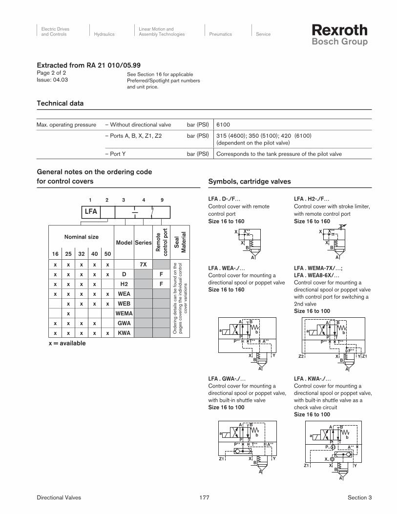
Technical data
Max. operating pressure – Without directional valve bar (PSI) 6100
– Ports A, B, X, Z1, Z2 bar (PSI) 315 (4600); 350 (5100); 420 (6100)
(dependent on the pilot valve)
– Port Y bar (PSI) Corresponds to the tank pressure of the pilot valve
Symbols, cartridge valves
General notes on the ordering code
for control covers
LFA
1 2 3 4 9
Extracted from RA 21 010/05.99Page 2 of 2
Issue: 04.03
LFA . D-./F…
Control cover with remote
control port
Size 16 to 160
LFA . H2-./F…
Control cover with stroke limiter,
with remote control port
Size 16 to 160
LFA . WEMA-7X/…;
LFA . WEA8-6X/…
Control cover for mounting a
directional spool or poppet valve
with control port for switching a
2nd valve
Size 16 to 100
LFA . WEA-./…
Control cover for mounting a
directional spool or poppet valve
Size 16 to 160
LFA . KWA-./…
Control cover for mounting a
directional spool or poppet valve,
with built-in shuttle valve as a
check valve circuit
Size 16 to 100
LFA . GWA-./…
Control cover for mounting a
directional spool or poppet valve,
with built-in shuttle valve
Size 16 to 100
X X**
XB
A
X X**
XB
A
a b
A
P T
B
P** T** A**
XB
A
Y
a b
A
P T
B
P** T**
F**
Z2 XB
A
Y Z1
a b
A
P T
B
P** T** A**
Z1 XB
A
Y
a b
A
P T
B
A**P..
X..
Z1 XB
A
Y
x = available
Nominal sizeModel Series
Re
mo
te
co
ntr
ol p
ort
Se
al
Mate
rial
16 25 32 40 50
x x x x x 7X
Ord
ering
deta
ils c
an b
e f
ound
on t
he
pag
es c
ove
ring
the ind
ivid
ual co
ntr
ol
co
ver
variatio
ns
x x x x x D F
x x x x H2 F
x x x x x WEA
x x x x WEB
x WEMA
x x x x GWA
x x x x x KWA
Directional Valves 178 Section 3
Electric Drivesand Controls Hydraulics
Linear Motion andAssembly Technologies Pneumatics Service
See Section 16 for applicable
Preferred/Spotlight part numbers
and unit price.
Ordering code
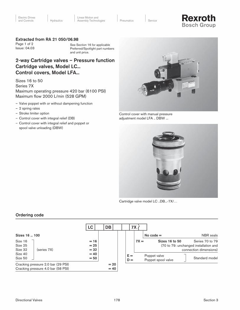
Cartridge valve model LC ..DB...-7X/…
Control cover with manual pressure
adjustment model LFA .. DBW ...
No code = NBR seals
7X = Sizes 16 to 50 Series 70 to 79
(70 to 79: unchanged installation and
connection dimensions)
E =
D =
Poppet valve
Poppet spool valveStandard model
Sizes 16 ... 100
Size 16
Size 25
Size 32
Size 40
Size 50
(series 7X)
= 16
= 25
= 32
= 40
= 50
Cracking pressure 2.0 bar (29 PSI)
Cracking pressure 4.0 bar (58 PSI)
= 20
= 40
Extracted from RA 21 050/06.98Page 1 of 2
Issue: 04.03
2-way Cartridge valves – Pressure function
Cartridge valves, Model LC...
Control covers, Model LFA...
Sizes 16 to 50
Series 7X
Maximum operating pressure 420 bar (6100 PSI)
Maximum fl ow 2000 L/min (528 GPM)
– Valve poppet with or without dampening function
– 2 spring rates
– Stroke limiter option
– Control cover with integral relief (DB)
– Control cover with integral relief and poppet or
spool valve unloading (DBW)
LC DB 7X /

Directional Valves 179 Section 3
Electric Drivesand Controls Hydraulics
Linear Motion andAssembly Technologies Pneumatics Service
See Section 16 for applicable
Preferred/Spotlight part numbers
and unit price.
Technical data
2-way cartridge valve
Max. operating pressure at ports A and B bar (PSI) Up to 420 (6100)
Nominal size 16 25 32 40 50
Max. fl ow (recommendation) L/min
(GPM)
300
(79.3)
450
(118.9)
600
(158.5)
1000
(264.2)
1600
(422.7)Poppet valve insert LC..DB..E../..
Spool valve insert LC..DB..D../.. L/min
(GPM)
175
(46.2)
300
(79.3)
450
(118.9)
700
(184.5)
1400
(369.8)
x = available
General notes on the ordering code
for control covers
LFA
1 2 3 4 5
Nominal size
Model
Co
ntr
ol
Mo
de
l
Series
Se
al
Mate
rial
16 25 32 40 50
x x x x x 7X
x x x x DB
x x x x x DBW
Extracted from RA 21 050/06.98Page 2 of 2
Issue: 04.03
Y
A
X
X**
B
F**
X
Symbols
LFA..DB.-../..
Size 16 to 50
LFA..DBW.-../..
Size 16 to 50
BA
PP**
X
X**
X Y
YD**
T
F**
a
B
A
PT

Electric Drivesand Controls Hydraulics
Linear Motion andAssembly Technologies Pneumatics Service
Directional Valves 180 Section 3
Notes
Related Documents