Section 3 AMERICAN Ductile Iron Pipe

Welcome message from author
This document is posted to help you gain knowledge. Please leave a comment to let me know what you think about it! Share it to your friends and learn new things together.
Transcript

Section 3
AMERICANDuctile Iron Pipe
3-1
AMERICAN Ductile Iron PipeCentrifugally Cast in Metal Molds or Sand-Lined Molds
For Water or Other Liquids.What is AMERICAN Ductile Iron? The ideal of cast iron with ductility, long sought by metallurgists, was real-ized with the introduction of ductile iron in 1948. Acclaimed to be one of the most sig-nificant metallurgical developments in this century, ductile iron has had an increasing impact in many industries. Ductile iron has ductility—as the name implies—and in ad-dition, it has strength and impact resistance far greater than that of gray iron; yet it retains the proven corrosion resistance of gray iron, thus making it an ideal piping material. American Cast Iron Pipe Company pioneered in the development of ductile iron pipe and produced experimental casts of ductile pipe and fittings as early as 1948. In 1949 Mr. C.K. Donoho, AMERICAN’s chief metallurgist, authored a paper on
the amazing properties of this new metal. Following this experimental work, the first shipment of AMERICAN Ductile Iron pipe was made in 1955. Production of ductile iron pipe has grown steadily and it is now a predominant piping material for conveying water and other liquids. Ductile iron is produced by treating molten low-sulfur base iron with magne-sium under closely controlled conditions. The startling change in the metal is charac-terized by the free graphite in ductile iron being deposited in spheroidal or nodular form instead of flake form as in gray iron. With the free graphite in nodular form, the continuity of the metal matrix is at a maxi-mum, accounting for the formation of a far stronger, tougher ductile material greatly exceeding gray iron in strength, in ductility, and in impact characteristics.
Photomicrograph showing graphite form in gray iron.
Photomicrograph showing graphite form in ductile iron.
AMERICAN Ductile Iron-Grade 60-42-10Minimum Physical Properties
AWWA C151
These properties are verified by tensile samples taken from the wall of the pipe.
Tensile Strength........................60,000 psiYield Strength...........................42,000 psiElongation................................10 percent
Fig. 3-1

3-2
AMERICAN Ductile Iron pipe provides...
High Impact Resistance AMERICAN Ductile Iron pipe has the high impact strength and toughness to withstand shocks usually encountered in transportation, handling and installation. These characteristics also provide added security against stresses induced by water hammer, highway traffic and unexpected adverse forces. Excellent impact resistance is confirmed by tests made at regular in-tervals in accordance with ANSI/AWWA C151/A21.51 Standard.
Superior Strength AMERICAN utilizes the ideal combi-nation of chemical analysis and heat treat-ment to produce a pipe with the most desirable combination of high strength and excellent ductility...a pipe that will withstand high internal pressure and deep cover...a pipe providing added reliability and additional factors of safety for normal and for unusual conditions such as ex-pansive soils and earth movement due to freezing and thawing.
Conservation of Energy and Lower Pumping Costs Head losses in piping are directly re-lated to inside diameters, and energy con-sumption and accompanying pumping costs are directly related to head losses. Therefore, the use of ductile iron piping having inside diameters greater than nomi-nal can result in significant energy savings over the years. In addition to helping to keep operating costs and utility rates rea-sonable, this conservation of energy is also helpful to the environment.
Assured, Proven Long Life Historical records document the prov-en service for centuries of gray cast iron pipe. Extensive laboratory and field tests conducted by many authorities under vari-ous installation conditions prove the soil corrosion resistance of ductile iron is at least as good as, if not better than, that of gray cast iron. The outstanding resistance of ductile iron pipe to soil corrosion has been verified by more than four decades of service.
After receiving the full force of a 4,500 pound weight dropped from a height of 30 feet, this 30” AMERICAN Ductile Iron pipe was severely deformed but did not fail.
Design ofAMERICAN Ductile Iron Pipe
The principal standards covering ductile iron pipe are ANSI/AWWA C150/A21.50 and ANSI/AWWA C151/A21.51. These and other standards are referenced throughout this Section either by the full
ANSI/AWWA designation or by only the AWWA numbering, such as AWWA C150.
AMERICAN Ductile Iron pipe is designed for combinations of internal pressure, water hammer, earth load and truck load. Thicknesses are determined in accordance with ANSI/AWWA C150/ A21.50, employing design methods ap-plicable to flexible pipe. Utilizing the principal mechanical properties of high
tensile strength, ductility and impact re-sistance, the design of ductile iron pipe is conservative in all respects and embodies high factors of safety. For qualification of pipe these properties are confirmed dur-ing production by frequent tensile and impact tests of specimens from the wall of pipe.

3-3
Physical Properties The ductile iron in AMERICAN pipe is grade 60-42-10, an annealed grade with the following specified minimum prop-erties: tensile strength, 60,000 psi; yield strength, 42,000 psi; elongation, 10 per-cent. A typical stress-strain curve obtained on a tensile specimen from the wall of duc-tile iron pipe shows that the pipe metal is an elastic material; that is, its stress-strain relation is linear over a substantial portion of the ultimate strength range. The aver-age modulus of elasticity is 24,000,000 psi, the value used in the design equations. Be-yond the yield point the metal continues to exhibit substantial ductility before ultimate failure. The high tensile strength of ductile iron allows the use of diameter-to-thick-ness ratios in which the deflection of the pipe, under trench loads, is of sufficient magnitude that the principles of flexible pipe design are applicable.
Design Steps 1. Pipe is designed for internal pres-sure including working pressure and surge pressure as follows: Working pressure is the specified design working pressure. Surge pressure is 100 psi unless a different surge pressure is specified by the buyer or his engineer. The design internal pressure in psi is the safety factor 2.0 multiplied by the sum of the working pressure and the surge pressure (100 psi). The metal design strength is the minimum yield strength in tension of 42,000 psi. 2. Pipe is designed for external loads including both earth load and truck load as follows: Earth load is based on the prism load concept and normally conservative weight of backfill soil of 120 lb/cu.ft.
Truck load is based on an AASHTO H-20 truck with 16,000-lb wheel load and 1.5 impact factor considered at all depths for all sizes of pipe. The ring bending stress used in design is 48,000 psi. The maximum pipe deflec-tion used in the design of cement-lined pipe is 3%. The design values for the five types of standard laying conditions in AWWA C150 and C151 (see Fig. 3-2, page 3-12) are as follows: Type 1: E’= 150 Bedding Angle = 30° Type 2: E’= 300 Bedding Angle = 45° Type 3: E’= 400 Bedding Angle = 60° Type 4: E’= 500 Bedding Angle = 90° Type 5: E’= 700 Bedding Angle = 150°
3. The larger net thickness is selected from the internal pressure design thickness and the bending stress design thickness. To this thickness is added a service allow-ance of 0.08”. The minimum thickness for deflection is then calculated and compared to that thickness. The larger of the two is selected. A casting tolerance is then add-ed, giving the total design thickness of the pipe. Casting tolerances are listed in Table No. 3-1. 4. The pressure class thickness is de-termined by the selection of a standard pressure class thickness from Table No. 3-8. If the calculated thickness is between two standard pressure class thicknesses, the larger of the two is selected. Later in this Section, tables show thicknesses of ductile pipe for a number of different pressures and depths of cover. For conditions not covered in tables, all formu-las and data for designing ductile iron pipe are given in AWWA C150.

3-4
Manufacture of AMERICAN Ductile Iron Pipe AMERICAN Ductile Iron pipe is cast centrifugally in nominal 20-foot laying lengths by the deLavaud process. After the careful proportioning of se-lect high-quality raw materials, the melting of iron for the manufacture of AMERICAN Ductile Iron pipe takes place in one of the world’s largest iron melting facilities under continually controlled conditions. AMERICAN also owns and operates one of the most impressive and modern scrap recycling facilities in the world. This facility ensures a dependable supply of high-quality shredded ferrous scrap for the production of high-quality piping products, conserving valuable natural resources in the process. This means, unlike many other types of pipe materials, AMERICAN Ductile Iron pipe is manufactured using predomi-nantly recycled iron and steel, not virgin materials. The melting process utilizes a control computer in the operation of the highly sophisticated electronic and mechanical components of the system. Rigid clean air requirements are satisfied through modern emission control equipment. Molten iron flows from a Contiarc furnace and/or cupola, and in the melt-ing facility is collected in 60-ton capacity
ladles where it is desulfurized. From here the iron is transferred into a 1300-ton holder which provides a reservoir of iron of uniform chemistry. The molten iron is then transferred from the holder to coreless electric induction furnaces where chemistry and temperature are adjusted to the pre-cise requirements of each production unit. The iron is then ready for treatment with magnesium, the most important step in the production of ductile iron, requiring close control of both the mechanics of the op-eration and the final chemistry of the iron. After treatment, each ladle is checked for exact content of magnesium and other ele-ments, and the metal is sent to the produc-tion area for pouring. The molten iron is introduced into a horizontal rotating mold with the quantity of the metal poured controlling the pipe thickness. The centrifugal force generated by rotation holds the metal against the mold wall and forces lighter, non-metallic impurities to the inside of the pipe to be removed in the cleaning process. After the iron has solidified, the casting machine is stopped and the pipe is stripped from the mold. All AMERICAN Ductile Iron pipe is annealed in modern heat treating ovens
View of modern plant where the large-diameter sizes of pipe are centrifugally cast in nominal 20-foot lengths by the deLavaud process.

3-5
with precisely controlled time and tem-perature cycles to produce optimum physi-cal properties. The pipe is then moved to processing stations where it is cleaned, machined, hydrostatically tested, lined and coated, and given final inspection. AMERICAN Ductile Iron pipe in sizes 4” through 64” is manufactured in ac-cordance with and meets or exceeds all applicable requirements of AWWA C151 Standard for “Ductile Iron Pipe, Centrifu-gally Cast, for Water or Other Liquids.” The quality of AMERICAN’s products and conformance to appropriate specifica-tions is assured by the British Standards Institute’s certification that AMERICAN’s quality system complies with the ISO 9001 Quality Management System Standard.
GENERAL REQUIREMENTS AMERICAN Ductile Iron pipe, with Fastite or mechanical joints, complies with AWWA C151 and the joints meet require-ments of AWWA C111. The outside diam-eters of 4”-48” are the same as for gray iron pipe that was formerly manufactured per AWWA C106 or C108, making ductile iron pipe completely interchangeable with gray iron pipe made to those standards with respect to joining diameters, accesso-ries and fittings. The installation of ductile iron pipe is covered in AWWA C600, including general
instructions for the assembly of push-on and mechanical joint pipe. See Section 2 of this Pipe Manual for detailed assembly in-structions for Fastite and Mechanical Joint pipe. The nominal laying length of the pipe is as shown in tables in this Section. A max-imum of 20 percent of the total number of pipes of each size specified in an order may be furnished as much as 24” shorter than the nominal laying length, and an addition-al 10 percent may be furnished as much as 6” shorter than nominal laying length.
Dimensions The plain end, the socket of the pipe, and the accessories are gauged at suffi-ciently frequent intervals to ensure that the dimensions comply with the requirements of AWWA C151.
Thickness Minus thickness tolerances of pipe are shown below: Table No. 3-1
Sizein.
Minus Tolerancein.
4”–8” 0.05
10”–12” 0.06
14”–42” 0.07
48” 0.08
54”–64” 0.09
During production, each ladle of ductile iron is checked for exact content of magne-sium and other elements with this computer-controlled optical emission spectrometer.
3-6
An additional minus tolerance of 0.02” is permitted along the barrel of the pipe for a dis-tance not to exceed 12”.
Weight The weight tolerance of pipe is minus 6 percent for pipe 12” and smaller in diameter, and minus 5 percent for pipe larger than 12” in diameter.
COATINGS AND LININGSOutside Coating The outside coating for use under normal conditions is an asphaltic coating approximate-ly 1 mil thick as specified in AWWA C151. The coating is applied to the outside of all pipe, un-less otherwise specified. See Section 11.Inside Lining AMERICAN Ductile Iron pipe for water service is normally furnished with standard ce-ment lining on the inside as specified in AWWA C104. For other types of service, pipe can be furnished uncoated inside or with cement lin-ing, asphaltic lining or with other linings as may be required to meet service conditions and as agreed upon at time of purchase.
For more detailed information on coatings and linings see Section 11.
TESTING To ensure that the properties of the fin-ished pipe meet or exceed the requirements of AWWA C151 and those of AMERICAN’s qual-ity control program, continuous inspection and testing are performed.Spectral Analysis Following magnesium treatment of the molten metal, a sample is poured from each ladle for spectral analysis. Within minutes, the amount of magnesium and other elements in the iron is determined. This early verification of the metal composition is a vital factor in the control of pipe quality.Tensile Test The physical characteristics of the pipe are continually checked by tensile tests made at a frequency of at least one such test during each casting period of approximately 3 hours. The tensile test specimens are cut from the pipe wall, and are machined from the midsection for testing. The acceptance values for test speci-mens are as follows:
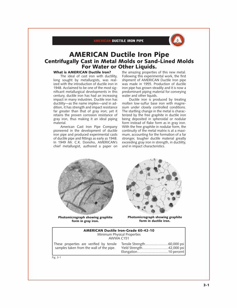
Each 30” and larger diameter AMERICAN Ductile Iron pipe is hydrostatically tested to 75% of yield strength which results in higher test pressures than those required by AWWA C151, varying to over 900 psi, depending on size and thickness of the pipe.
3-7
Grade of Iron: 60-42-10Minimum tensile strength.................60,000 psiMinimum yield strength...................42,000 psiMinimum elongation.......................10 percent
Impact Test Impact tests are made on at least one sample machined from the pipe wall dur-ing each operating hour to ensure the de-sired toughness in the finished pipe. Notched Charpy impact tests are performed in accor-dance with ASTM E23, except that specimen size is 0.500” by full thickness of the pipe wall. The corrected acceptance value for this test is a minimum of 7 ft-lb for tests conducted at 70°F ± 10°. Low-temperature impact tests are made from at least 10% of the test pipe to ensure compliance with a minimum corrected value of 3 ft-lb for tests conducted at -40°F ± 2°F.
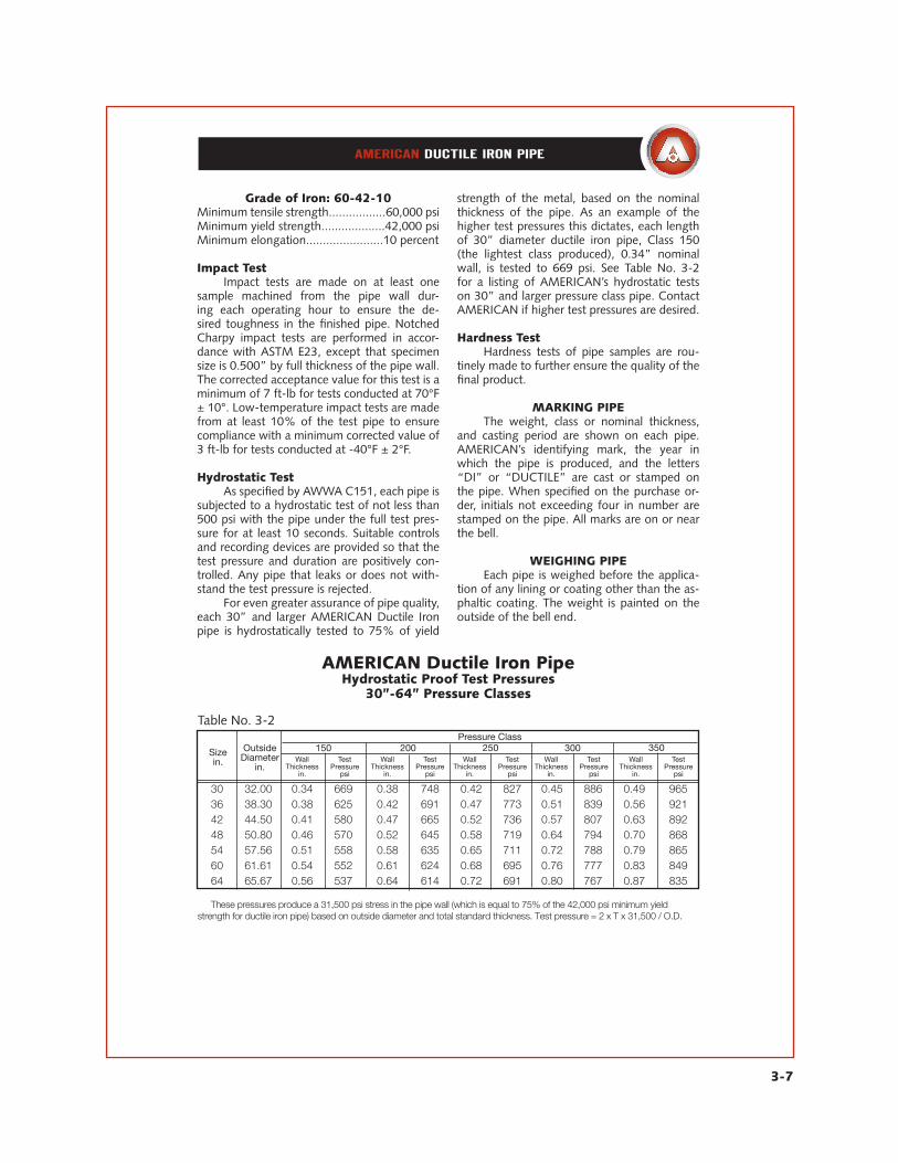
Hydrostatic Test As specified by AWWA C151, each pipe is subjected to a hydrostatic test of not less than 500 psi with the pipe under the full test pres-sure for at least 10 seconds. Suitable controls and recording devices are provided so that the test pressure and duration are positively con-trolled. Any pipe that leaks or does not with-stand the test pressure is rejected. For even greater assurance of pipe quality, each 30” and larger AMERICAN Ductile Iron pipe is hydrostatically tested to 75% of yield
strength of the metal, based on the nominal thickness of the pipe. As an example of the higher test pressures this dictates, each length of 30” diameter ductile iron pipe, Class 150 (the lightest class produced), 0.34” nominal wall, is tested to 669 psi. See Table No. 3-2 for a listing of AMERICAN’s hydrostatic tests on 30” and larger pressure class pipe. Contact AMERICAN if higher test pressures are desired.
Hardness Test Hardness tests of pipe samples are rou-tinely made to further ensure the quality of the final product.
MARKING PIPE The weight, class or nominal thickness, and casting period are shown on each pipe. AMERICAN’s identifying mark, the year in which the pipe is produced, and the letters “DI” or “DUCTILE” are cast or stamped on the pipe. When specified on the purchase or-der, initials not exceeding four in number are stamped on the pipe. All marks are on or near the bell.
WEIGHING PIPE Each pipe is weighed before the applica-tion of any lining or coating other than the as-phaltic coating. The weight is painted on the outside of the bell end.
AMERICAN Ductile Iron PipeHydrostatic Proof Test Pressures
30”-64” Pressure Classes
Table No. 3-2
Size in.
Outside Diameter
in.
Pressure Class150 200 250 300 350
Wall Thickness
in.
TestPressure
psi
Wall Thickness
in.
TestPressure
psi
Wall Thickness
in.
TestPressure
psi
Wall Thickness
in.
TestPressure
psi
Wall Thickness
in.
TestPressure
psi
30 32.00 0.34 669 0.38 748 0.42 827 0.45 886 0.49 965 36 38.30 0.38 625 0.42 691 0.47 773 0.51 839 0.56 921 42 44.50 0.41 580 0.47 665 0.52 736 0.57 807 0.63 892 48 50.80 0.46 570 0.52 645 0.58 719 0.64 794 0.70 868 54 57.56 0.51 558 0.58 635 0.65 711 0.72 788 0.79 865 60 61.61 0.54 552 0.61 624 0.68 695 0.76 777 0.83 849 64 65.67 0.56 537 0.64 614 0.72 691 0.80 767 0.87 835
These pressures produce a 31,500 psi stress in the pipe wall (which is equal to 75% of the 42,000 psi minimum yield strength for ductile iron pipe) based on outside diameter and total standard thickness. Test pressure = 2 x T x 31,500 / O.D.
3-8
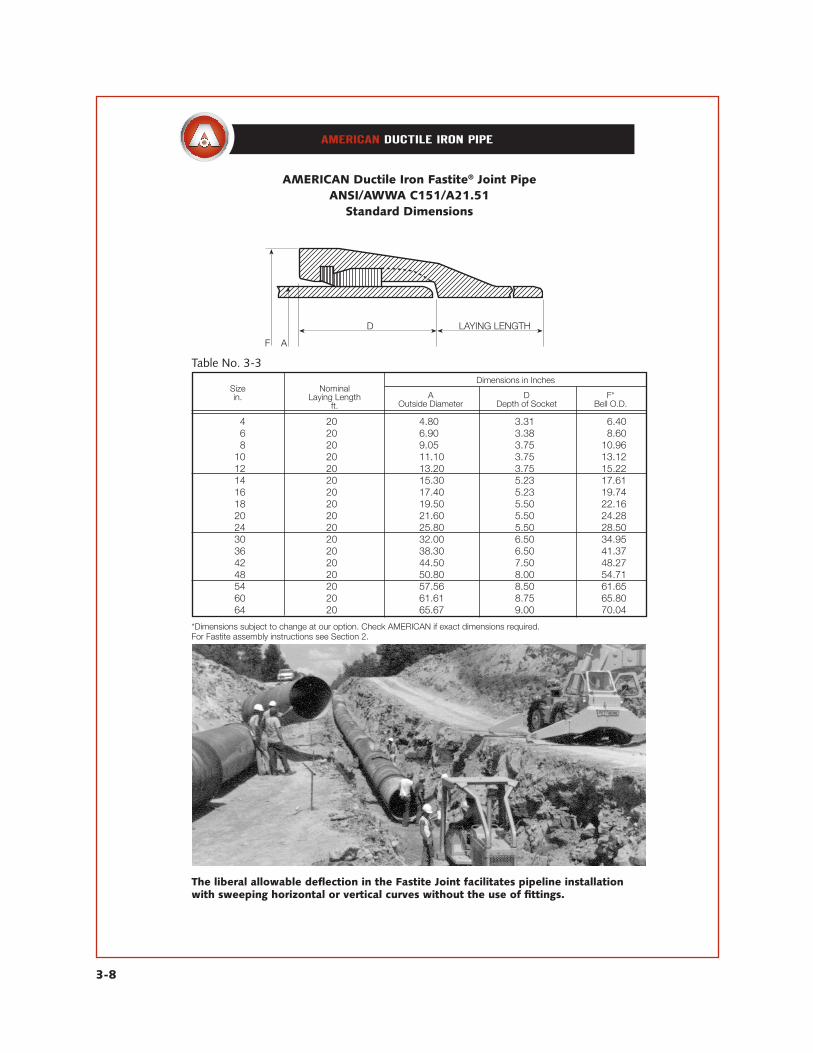
AMERICAN Ductile Iron Fastite® Joint PipeANSI/AWWA C151/A21.51
Standard Dimensions
Table No. 3-3
Sizein.
Dimensions in InchesNominal
Laying Lengthft.
AOutside Diameter
DDepth of Socket
F*Bell O.D.
4 20 4.80 3.31 16.40 6 20 6.90 3.38 18.60 8 20 9.05 3.75 10.96 10 20 11.10 3.75 13.12 12 20 13.20 3.75 15.22 14 20 15.30 5.23 17.61 16 20 17.40 5.23 19.74 18 20 19.50 5.50 22.16 20 20 21.60 5.50 24.28 24 20 25.80 5.50 28.50 30 20 32.00 6.50 34.95 36 20 38.30 6.50 41.37 42 20 44.50 7.50 48.27 48 20 50.80 8.00 54.71 54 20 57.56 8.50 61.65 60 20 61.61 8.75 65.80 64 20 65.67 9.00 70.04
*Dimensions subject to change at our option. Check AMERICAN if exact dimensions required.For Fastite assembly instructions see Section 2.
The liberal allowable deflection in the Fastite Joint facilitates pipeline installation with sweeping horizontal or vertical curves without the use of fittings.
3-9
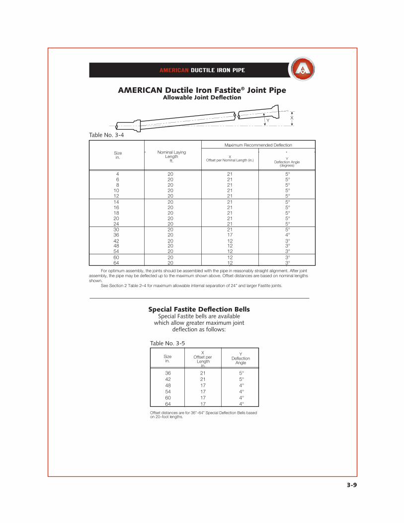
AMERICAN Ductile Iron Fastite® Joint PipeAllowable Joint Deflection
Table No. 3-5
Special Fastite Deflection BellsSpecial Fastite bells are available
which allow greater maximum joint deflection as follows:
Sizein.
X Offset per Length
in.
YDeflection
Angle
36 21 5° 42 21 5° 48 17 4° 54 17 4° 60 17 4° 64 17 4°
XOffset per Nominal Length (in.) Y
Deflection Angle(degrees)
Table No. 3-4
Sizein.
Nominal Laying Length
ft.
Maximum Recommended Deflection
14 20 21 5° 16 20 21 5° 18 20 21 5° 10 20 21 5° 12 20 21 5° 14 20 21 5° 16 20 21 5° 18 20 21 5° 20 20 21 5° 24 20 21 5° 30 20 21 5° 36 20 17 4° 42 20 12 3° 48 20 12 3° 54 20 12 3° 60 20 12 3° 64 20 12 3°
For optimum assembly, the joints should be assembled with the pipe in reasonably straight alignment. After joint assembly, the pipe may be deflected up to the maximum shown above. Offset distances are based on nominal lengths shown. See Section 2 Table 2–4 for maximum allowable internal separation of 24” and larger Fastite joints.
Offset distances are for 36”–64” Special Deflection Bells based on 20–foot lengths.
3-10
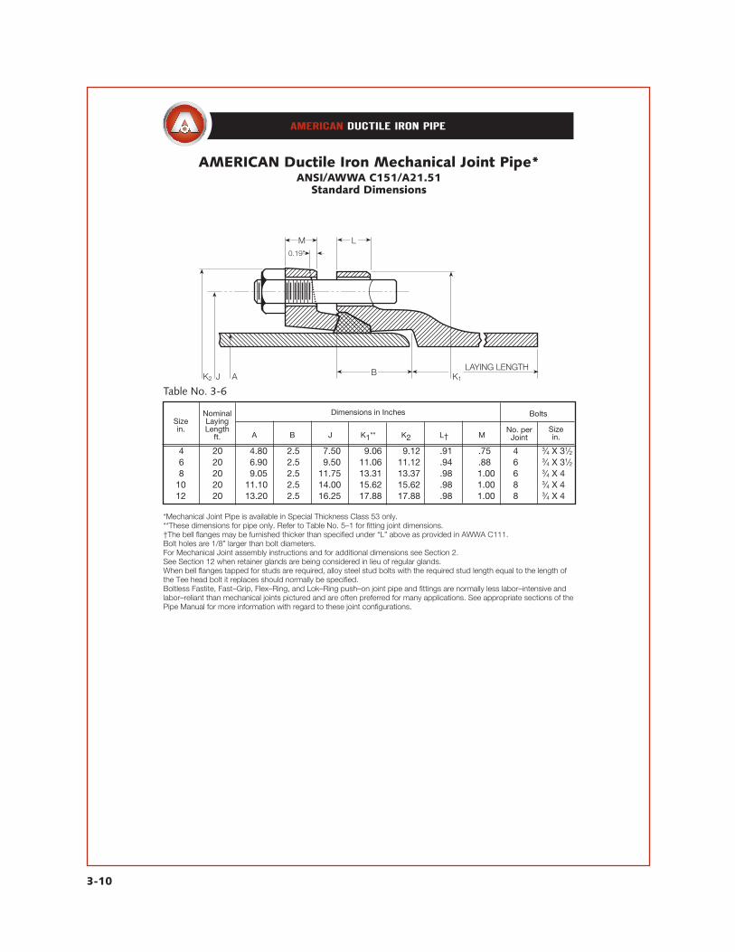
AMERICAN Ductile Iron Mechanical Joint Pipe*ANSI/AWWA C151/A21.51
Standard Dimensions
Table No. 3-6
Sizein.
Nominal Laying Length
ft. A B J K1** K2 L† MNo. per
Joint
Bolts
Sizein.
Dimensions in Inches
4 20 4.80 2.5 7.50 9.06 9.12 .91 .75 4 3⁄4 X 31⁄2 6 20 6.90 2.5 9.50 11.06 11.12 .94 .88 6 3⁄4 X 31⁄2 8 20 9.05 2.5 11.75 13.31 13.37 .98 1.00 6 3⁄4 X 4 10 20 11.10 2.5 14.00 15.62 15.62 .98 1.00 8 3⁄4 X 4 12 20 13.20 2.5 16.25 17.88 17.88 .98 1.00 8 3⁄4 X 4
*Mechanical Joint Pipe is available in Special Thickness Class 53 only.**These dimensions for pipe only. Refer to Table No. 5–1 for fitting joint dimensions.†The bell flanges may be furnished thicker than specified under “L” above as provided in AWWA C111.Bolt holes are 1/8” larger than bolt diameters.For Mechanical Joint assembly instructions and for additional dimensions see Section 2.See Section 12 when retainer glands are being considered in lieu of regular glands.When bell flanges tapped for studs are required, alloy steel stud bolts with the required stud length equal to the length of the Tee head bolt it replaces should normally be specified.Boltless Fastite, Fast–Grip, Flex–Ring, and Lok–Ring push–on joint pipe and fittings are normally less labor–intensive and labor–reliant than mechanical joints pictured and are often preferred for many applications. See appropriate sections of the Pipe Manual for more information with regard to these joint configurations.

AMERICAN Ductile Iron Mechanical Joint PipeAllowable Joint Deflection
3-11
XOffset per Nominal Length (in.) Y
Deflection Angle (degrees)
Table No. 3-7
Sizein.
Nominal Laying Length
ft.
Maximum Recommended Deflection
4 18 31 8°–18’ 6 20 30 7°–07’ 8 20 22 5°–21’ 10 20 22 5°–21’ 12 20 22 5°–21’
The joint should be assembled with the pipe in reasonably straight alignment. Joint deflection to the maximum shown above may be made after assembly but before tightening bolts. Offset distances are based on nominal 18– or 20–foot lengths as shown.
3-12
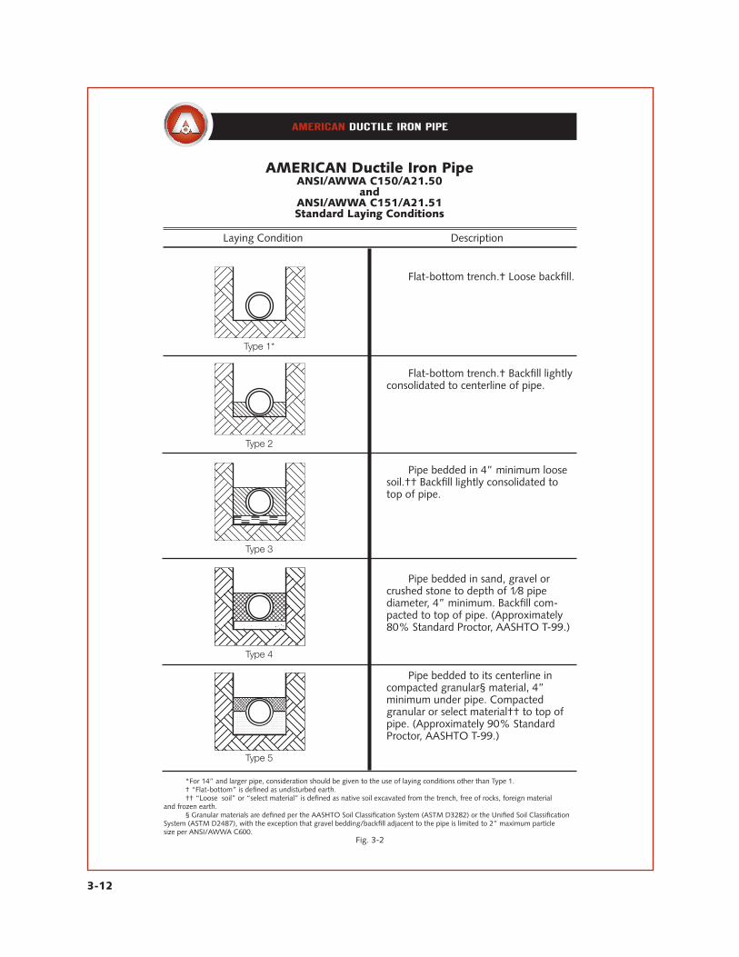
AMERICAN Ductile Iron PipeANSI/AWWA C150/A21.50
andANSI/AWWA C151/A21.51Standard Laying Conditions
Laying Condition Description
Flat-bottom trench.† Loose backfill.
Flat-bottom trench.† Backfill lightly consolidated to centerline of pipe.
Pipe bedded in 4” minimum loose soil.†† Backfill lightly consolidated to top of pipe.
Pipe bedded in sand, gravel or crushed stone to depth of 1⁄8 pipe diameter, 4” minimum. Backfill com-pacted to top of pipe. (Approximately 80% Standard Proctor, AASHTO T-99.)
Pipe bedded to its centerline in compacted granular§ material, 4” minimum under pipe. Compacted granular or select material†† to top of pipe. (Approximately 90% Standard Proctor, AASHTO T-99.)
*For 14” and larger pipe, consideration should be given to the use of laying conditions other than Type 1. † “Flat-bottom” is defined as undisturbed earth. †† “Loose soil” or “select material” is defined as native soil excavated from the trench, free of rocks, foreign material and frozen earth. § Granular materials are defined per the AASHTO Soil Classification System (ASTM D3282) or the Unified Soil Classification System (ASTM D2487), with the exception that gravel bedding/backfill adjacent to the pipe is limited to 2” maximum particle size per ANSI/AWWA C600.
Fig. 3-2

3-13
AMERICAN Ductile Iron PipeANSI/AWWA C150/A21.50
and ANSI/AWWA C151/A21.51
Standard Pressure Classes – Wall Thickness and Nominal Wall Thickness
Table No. 3-8
Size in.
Outside Diameter
in.
Pressure Class
150 200 250 300 350
4 4.80 – – – – 0.25 6 6.90 – – – – 0.25 8 9.05 – – – – 0.25 10 11.10 – – – – 0.26 12 13.20 – – – – 0.28 14 15.30 – – 0.28 0.30 0.31 16 17.40 – – 0.30 0.32 0.34 18 19.50 – – 0.31 0.34 0.36 20 21.60 – – 0.33 0.36 0.38 24 25.80 – 0.33 0.37 0.40 0.43 30 32.00 0.34 0.38 0.42 0.45 0.49 36 38.30 0.38 0.42 0.47 0.51 0.56 42 44.50 0.41 0.47 0.52 0.57 0.63 48 50.80 0.46 0.52 0.58 0.64 0.70 54 57.56 0.51 0.58 0.65 0.72 0.79 60 61.61 0.54 0.61 0.68 0.76 0.83 64 65.67 0.56 0.64 0.72 0.80 0.87 Pressure classes are defined as the rated water working pressure of the pipe in psi. The thicknesses shown are adequate for the rated water working pressure plus a surge allowance of 100 psi. Calculations result in net thicknesses andare based on a minimum yield strength in tension of 42,000 psi and 2.0 safety factor times the sum of working pressureand 100 psi surge allowance. Thickness can be calculated for rated water working pressure and surges other than the above by use of equation 1 inANSI/AWWA C150/A21.50. AMERICAN Ductile Iron pipe is available for water working pressures greater than 350 psi. Check AMERICAN for details. These are standard pressure classes as given in AWWA C150 and C151. AMERICAN can furnish any thickness inbetween these standard thicknesses if deemed economical for major projects. AMERICAN Ductile Iron pipe is also available with thicknesses greater than Pressure Class 350. For special applications,contact AMERICAN.
Nominal Thickness in Inches

3-14
AMERICAN Ductile IronFastite® Joint Pipe
ANSI/AWWA C151/A21.51Weights for Pressure Classes
Table No. 3-9
Sizein.
Pressure Class
WallThickness
in.Per FootPlain End Per Foot
inc. BellPer 20’ Nominal
Length
Weight in Pounds
Fastite Joint
4 350 0.25 10.9 11.3 226 6 350 0.25 16.0 16.7 335 8 350 0.25 21.1 22.1 445 10 350 0.26 27.1 28.5 575 12 350 0.28 34.8 36.4 730 14 250 0.28 40.4 42.4 855 300 0.30 43.3 45.3 915 350 0.31 44.7 46.7 940 16 250 0.30 49.3 51.5 1035 300 0.32 52.5 54.8 1100 350 0.34 55.8 58.0 1165 18 250 0.31 57.2 60.8 1220 300 0.34 62.6 66.2 1325 350 0.36 66.2 69.8 1400 20 250 0.33 67.5 71.5 1430 300 0.36 73.5 77.5 1555 350 0.38 77.5 81.5 1635 24 200 0.33 80.8 85.6 1715 250 0.37 90.5 95.3 1910 300 0.40 97.7 102.5 2055 350 0.43 104.9 109.7 2200 30 150 0.34 103.5 111.7 2240 200 0.38 115.5 123.7 2480 250 0.42 127.5 135.7 2720 300 0.45 136.5 144.7 2900 350 0.49 148.4 156.6 3140 36 150 0.38 138.5 149.2 2990 200 0.42 152.9 163.6 3280 250 0.47 170.9 181.6 3640 300 0.51 185.3 196.0 3930 350 0.56 203.2 213.9 4285 42 150 0.41 173.8 189.6 3790 200 0.47 198.9 214.7 4295 250 0.52 219.9 235.6 4710 300 0.57 240.7 256.5 5130 350 0.63 265.7 281.4 5630 48 150 0.46 222.6 242.1 4840 200 0.52 251.3 270.8 5415 250 0.58 280.0 299.5 5990 300 0.64 308.6 328.1 6560 350 0.70 337.1 356.6 7130
Weights for all sizes are for 20–ft nominal lengths. Dimensions, lengths, weights, etc., are subject to change at our option.

64 150 0.56 350.5 384.4 7685
3-15
AMERICAN Ductile IronFastite Joint Pipe
ANSI/AWWA C151/A21.51Weights for Pressure Classes
Table No. 3-9—Continued
Sizein.
Pressure Class
WallThickness
in.Per FootPlain End Per Foot
inc. BellPer 20’
Nominal Length
Weight in Pounds
Fastite Joint
54 150 0.51 279.7 305.5 6110 200 0.58 317.7 343.5 6870 250 0.65 355.6 381.4 7605 300 0.72 393.4 419.2 8360 350 0.79 431.1 456.9 9110 60 150 0.54 317.0 345.5 6910 200 0.61 357.7 386.2 7725 250 0.68 398.3 426.8 8535 300 0.76 444.6 473.0 9460 350 0.83 485.0 513.4 10270
200 0.64 400.1 433.9 8680 250 0.72 449.6 483.4 9670 300 0.80 498.9 532.7 10655 350 0.87 542.0 575.8 11515
60” AMERICAN Fastite® Joint Ductile Iron pipe being installed as a water transmis-sion main.

3-16
AMERICAN Ductile Iron PipeANSI/AWWA C151/A21.51
Pressure Ratings and Depths of CoverMinimum Pressure Classes
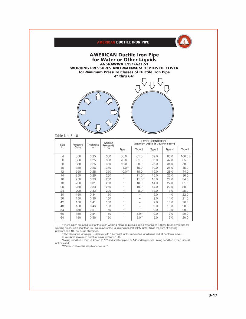
In Table No. 3-10 on the following page the relationships of Minimum Pressure Classes, rated working pressure and maximum depths of cover are tabulated. Following in Table No. 3-11 this same information is tabulated for all Pressure Classes. Information in these tables is based on the same conservative design prin-ciples as is the information shown in Table No. 14 of AWWA C150 and Table No. 51.3 of AWWA C151. The information included and the intended use of these tables are as follows:
Table No. 3-10—Working Pressure/ Maximum Depths of Cover for Minimum Pressure Classes In Table No. 3-10 are tabulated the corre-sponding nominal wall thickness, maximum rated working pressure, and maximum depth of cover for the five types of laying conditions, all for Mini-mum Pressure Classes of ductile iron pipe. The information in this table is taken from Table No. 3-11 and is offered as a convenience for those wanting to quickly check the capabili-ties of Minimum Pressure Classes of ductile iron pipe under a given set of conditions. For the majority of internal pressure and external load-ing conditions, Minimum Pressure Classes are more than adequate and possess substantial true safety factors.
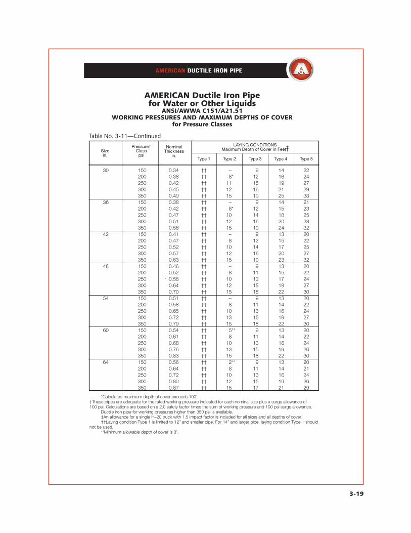
Table No. 3-11—Working Pressure/Maximum Depths of Cover In Table No. 3-11 are listed the standard Pressure Classes and for each class are tabu-
lated the corresponding nominal wall thick-ness, maximum rated working pressure, and maximum depths of cover for the five types of laying conditions. For any specified standard Pressure Class the nominal wall thickness, the maximum rated working pressure, and the maximum depth of cover for each standard laying condition can be determined. For any water working pressure of 150, 200, 250, 300 or 350 psi, the corresponding standard Pressure Class and nominal wall thick-ness can be determined. (Note: Although not listed in the following table, ductile iron pipe for working pressures higher than 350 psi is available. Consult AMERICAN regarding spe-cific conditions involved.) For any required depth of cover from 2.5’ up to the maximums shown in this table the Pressure Class and the corresponding nominal wall thickness can be determined for laying conditions Type 1 through Type 5.
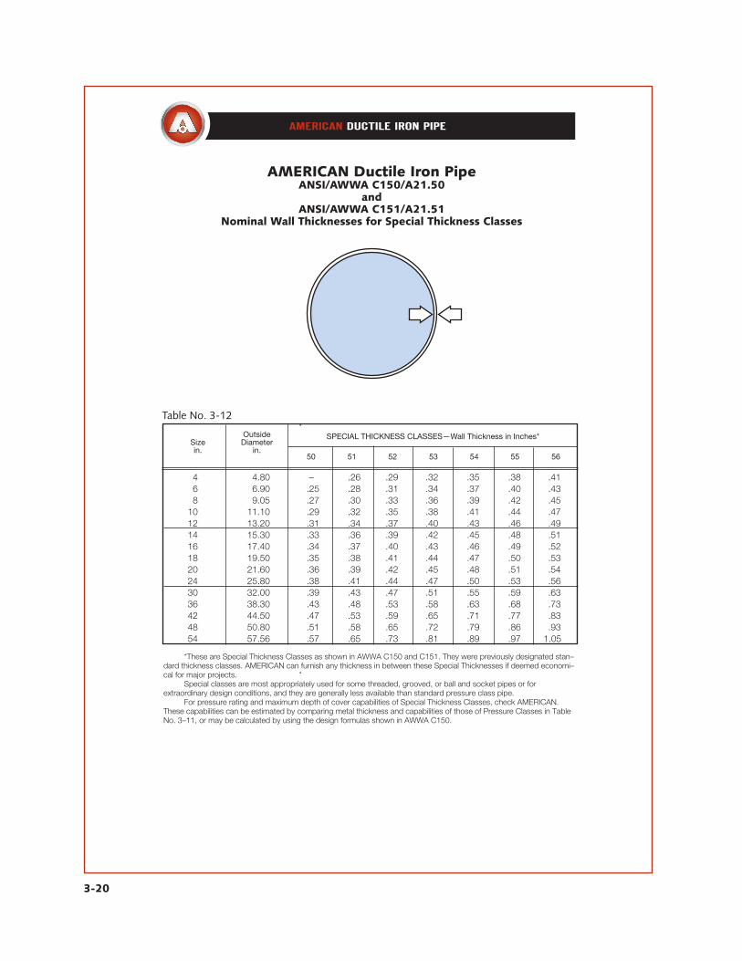
For other conditions not covered in these ta-bles see AWWA C150 or consult AMERICAN for design of pipe thickness. Special thickness classes shown in Table No. 3-12 may be ap-propriate in such cases.
Sizein.
3-17
AMERICAN Ductile Iron Pipefor Water or Other Liquids
ANSI/AWWA C151/A21.51WORKING PRESSURES AND MAXIMUM DEPTHS OF COVER
for Minimum Pressure Classes of Ductile Iron Pipe4” thru 64”
Table No. 3-10
PressureClass
Thicknessin.
WorkingPressure†
psi
LAYING CONDITIONSMaximum Depth of Cover in Feet††
Type 1 Type 2 Type 3 Type 4 Type 5
4 350 0.25 350 53.0 61.0 69.0 85.0 100.0‡ 6 350 0.25 350 26.0 31.0 37.0 47.0 65.0 8 350 0.25 350 16.0 20.0 25.0 34.0 50.0 10 350 0.26 350 11.0** 15.0 19.0 28.0 45.0 12 350 0.28 350 10.0** 15.0 19.0 28.0 44.0 14 250 0.28 250 * 11.0** 15.0 23.0 36.0 16 250 0.30 250 * 11.0** 15.0 24.0 34.0 18 250 0.31 250 * 10.0** 14.0 22.0 31.0 20 250 0.33 250 * 10.0 14.0 22.0 30.0 24 200 0.33 200 * 8.0** 12.0 17.0 25.0 30 150 0.34 150 * – 9.0 14.0 22.0 36 150 0.38 150 * – 9.0 14.0 21.0 42 150 0.41 150 * – 9.0 13.0 20.0 48 150 0.46 150 * – 9.0 13.0 20.0 54 150 0.51 150 * – 9.0 13.0 20.0 60 150 0.54 150 * 5.0** 9.0 13.0 20.0 64 150 0.56 150 * 5.0** 9.0 13.0 20.0
†These pipes are adequate for the rated working pressure plus a surge allowance of 100 psi. Ductile iron pipe for working pressures higher than 350 psi is available. Figures include 2.0 safety factor times the sum of working pressure and 100 psi surge allowance. ††An allowance for single H–20 truck with 1.5 impact factor is included for all sizes and all depths of cover. ‡Calculated maximum depth of cover exceeds 100’. *Laying condition Type 1 is limited to 12” and smaller pipe. For 14” and larger pipe, laying condition Type 1 should not be used. **Minimum allowable depth of cover is 3’.

3-18
Sizein.
AMERICAN Ductile Iron Pipefor Water or Other Liquids
ANSI/AWWA C151/A21.51WORKING PRESSURES AND MAXIMUM DEPTHS OF COVER
for Pressure Classes
Table No. 3-11
Pressure†Class
psi
NominalThickness
in.
LAYING CONDITIONSMaximum Depth of Cover in Feet††
Type 1 Type 2 Type 3 Type 4 Type 5
4 350 0.25 53 61 69 85 100* 6 350 0.25 23 31 37 47 65 8 350 0.25 16 20 25 34 50 10 350 0.26 11** 15 19 28 45 12 350 0.28 10** 15 19 28 44 14 250 0.28 †† 11** 15 23 36 300 0.30 †† 13 17 26 42 350 0.31 †† 14 19 27 44 16 250 0.31 †† 11** 15 24 34 300 0.32 †† 13 17 26 39 350 0.34 †† 15 20 28 44 18 250 0.31 †† 10** 14 22 31 300 0.34 †† 13 17 26 36 350 0.36 †† 15 19 28 41 20 250 0.33 †† 10 14 22 30 300 0.36 †† 13 17 26 35 350 0.38 †† 15 19 28 38 24 200 0.33 †† 8** 12 17 25 250 0.37 †† 11 15 20 29 300 0.40 †† 13 17 24 32 350 0.43 †† 15 19 28 37
See notes at end of table.
300 0.64 †† 12 15 19 27
LAYING CONDITIONSMaximum Depth of Cover in Feet††
3-19
Sizein.
AMERICAN Ductile Iron Pipefor Water or Other Liquids
ANSI/AWWA C151/A21.51WORKING PRESSURES AND MAXIMUM DEPTHS OF COVER
for Pressure Classes
Table No. 3-11—Continued
Pressure†Class
psi
NominalThickness
in.Type 1 Type 2 Type 3 Type 4 Type 5
30 150 0.34 †† – 9 14 22 200 0.38 †† 8* 12 16 24 250 0.42 †† 11 15 19 27 300 0.45 †† 12 16 21 29 350 0.49 †† 15 19 25 33 36 150 0.38 †† – 9 14 21 200 0.42 †† 8* 12 15 23 250 0.47 †† 10 14 18 25 300 0.51 †† 12 16 20 28 350 0.56 †† 15 19 24 32 42 150 0.41 †† – 9 13 20 200 0.47 †† 8 12 15 22 250 0.52 †† 10 14 17 25 300 0.57 †† 12 16 20 27 350 0.63 †† 15 19 23 32 48 150 0.46 †† – 9 13 20 200 0.52 †† 8 11 15 22 250 0.58 †† 10 13 17 24
350 0.70 †† 15 18 22 30 54 150 0.51 †† – 9 13 20 200 0.58 †† 8 11 14 22 250 0.65 †† 10 13 16 24 300 0.72 †† 13 15 19 27 350 0.79 †† 15 18 22 30 60 150 0.54 †† 5** 9 13 20 200 0.61 †† 8 11 14 22 250 0.68 †† 10 13 16 24 300 0.76 †† 13 15 19 26 350 0.83 †† 15 18 22 30 64 150 0.56 †† 2** 9 13 20 200 0.64 †† 8 11 14 21 250 0.72 †† 10 13 16 24 300 0.80 †† 12 15 19 26 350 0.87 †† 15 17 21 29
*Calculated maximum depth of cover exceeds 100’.†These pipes are adequate for the rated working pressure indicated for each nominal size plus a surge allowance of100 psi. Calculations are based on a 2.0 safety factor times the sum of working pressure and 100 psi surge allowance. Ductile iron pipe for working pressures higher than 350 psi is available. ‡An allowance for a single H–20 truck with 1.5 impact factor is included for all sizes and all depths of cover. ††Laying condition Type 1 is limited to 12” and smaller pipe. For 14” and larger pipe, laying condition Type 1 should not be used. **Minimum allowable depth of cover is 3’.
3-20
Sizein.
AMERICAN Ductile Iron PipeANSI/AWWA C150/A21.50
andANSI/AWWA C151/A21.51
Nominal Wall Thicknesses for Special Thickness Classes
Table No. 3-12
Outside Diameter
in.
SPECIAL THICKNESS CLASSES—Wall Thickness in Inches*
50 51 52 53 54 55 56
4 4.80 – .26 .29 .32 .35 .38 .41 6 6.90 .25 .28 .31 .34 .37 .40 .43 8 9.05 .27 .30 .33 .36 .39 .42 .45 10 11.10 .29 .32 .35 .38 .41 .44 .47 12 13.20 .31 .34 .37 .40 .43 .46 .49 14 15.30 .33 .36 .39 .42 .45 .48 .51 16 17.40 .34 .37 .40 .43 .46 .49 .52 18 19.50 .35 .38 .41 .44 .47 .50 .53 20 21.60 .36 .39 .42 .45 .48 .51 .54 24 25.80 .38 .41 .44 .47 .50 .53 .56 30 32.00 .39 .43 .47 .51 .55 .59 .63 36 38.30 .43 .48 .53 .58 .63 .68 .73 42 44.50 .47 .53 .59 .65 .71 .77 .83 48 50.80 .51 .58 .65 .72 .79 .86 .93 54 57.56 .57 .65 .73 .81 .89 .97 1.05
*These are Special Thickness Classes as shown in AWWA C150 and C151. They were previously designated stan–dard thickness classes. AMERICAN can furnish any thickness in between these Special Thicknesses if deemed economi–cal for major projects. Special classes are most appropriately used for some threaded, grooved, or ball and socket pipes or for extraordinary design conditions, and they are generally less available than standard pressure class pipe. For pressure rating and maximum depth of cover capabilities of Special Thickness Classes, check AMERICAN. These capabilities can be estimated by comparing metal thickness and capabilities of those of Pressure Classes in Table No. 3–11, or may be calculated by using the design formulas shown in AWWA C150.
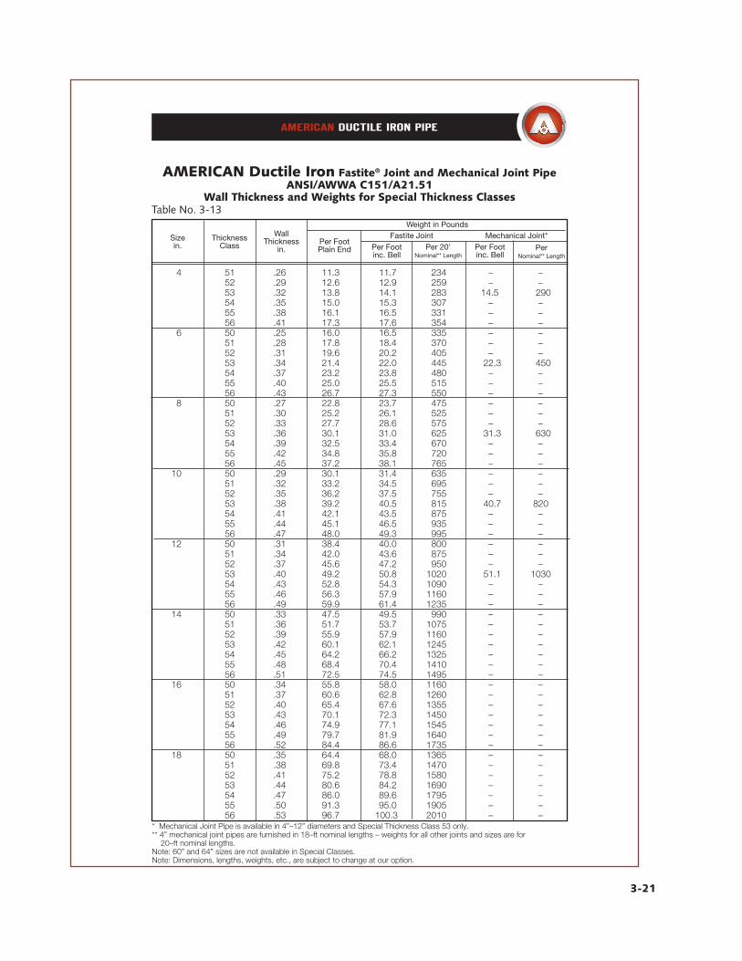
AMERICAN Ductile Iron Fastite® Joint and Mechanical Joint PipeANSI/AWWA C151/A21.51
Wall Thickness and Weights for Special Thickness Classes
3-21
Table No. 3-13
Sizein.
ThicknessClass
WallThickness
in.Per FootPlain End Per Foot
inc. BellPer 20’
Nominal** LengthPer Footinc. Bell
PerNominal** Length
Weight in PoundsFastite Joint Mechanical Joint*
4 51 .26 11.3 11.7 234 – – 52 .29 12.6 12.9 259 – – 53 .32 13.8 14.1 283 14.5 290 54 .35 15.0 15.3 307 – – 55 .38 16.1 16.5 331 – – 56 .41 17.3 17.6 354 – – 6 50 .25 16.0 16.5 335 – – 51 .28 17.8 18.4 370 – – 52 .31 19.6 20.2 405 – – 53 .34 21.4 22.0 445 22.3 450 54 .37 23.2 23.8 480 – – 55 .40 25.0 25.5 515 – – 56 .43 26.7 27.3 550 – – 8 50 .27 22.8 23.7 475 – – 51 .30 25.2 26.1 525 – – 52 .33 27.7 28.6 575 – – 53 .36 30.1 31.0 625 31.3 630 54 .39 32.5 33.4 670 – – 55 .42 34.8 35.8 720 – – 56 .45 37.2 38.1 765 – – 10 50 .29 30.1 31.4 635 – – 51 .32 33.2 34.5 695 – – 52 .35 36.2 37.5 755 – – 53 .38 39.2 40.5 815 40.7 820 54 .41 42.1 43.5 875 – – 55 .44 45.1 46.5 935 – – 56 .47 48.0 49.3 995 – – 12 50 .31 38.4 40.0 800 – – 51 .34 42.0 43.6 875 – – 52 .37 45.6 47.2 950 – – 53 .40 49.2 50.8 1020 51.1 1030 54 .43 52.8 54.3 1090 – – 55 .46 56.3 57.9 1160 – – 56 .49 59.9 61.4 1235 – – 14 50 .33 47.5 49.5 990 – – 51 .36 51.7 53.7 1075 – – 52 .39 55.9 57.9 1160 – – 53 .42 60.1 62.1 1245 – – 54 .45 64.2 66.2 1325 – – 55 .48 68.4 70.4 1410 – – 56 .51 72.5 74.5 1495 – – 16 50 .34 55.8 58.0 1160 – – 51 .37 60.6 62.8 1260 – – 52 .40 65.4 67.6 1355 – – 53 .43 70.1 72.3 1450 – – 54 .46 74.9 77.1 1545 – – 55 .49 79.7 81.9 1640 – – 56 .52 84.4 86.6 1735 – – 18 50 .35 64.4 68.0 1365 – – 51 .38 69.8 73.4 1470 – – 52 .41 75.2 78.8 1580 – – 53 .44 80.6 84.2 1690 – – 54 .47 86.0 89.6 1795 – – 55 .50 91.3 95.0 1905 – – 56 .53 96.7 100.3 2010 – – * Mechanical Joint Pipe is available in 4”–12” diameters and Special Thickness Class 53 only.** 4” mechanical joint pipes are furnished in 18–ft nominal lengths – weights for all other joints and sizes are for 20–ft nominal lengths.Note: 60” and 64” sizes are not available in Special Classes.Note: Dimensions, lengths, weights, etc., are subject to change at our option.
3-22
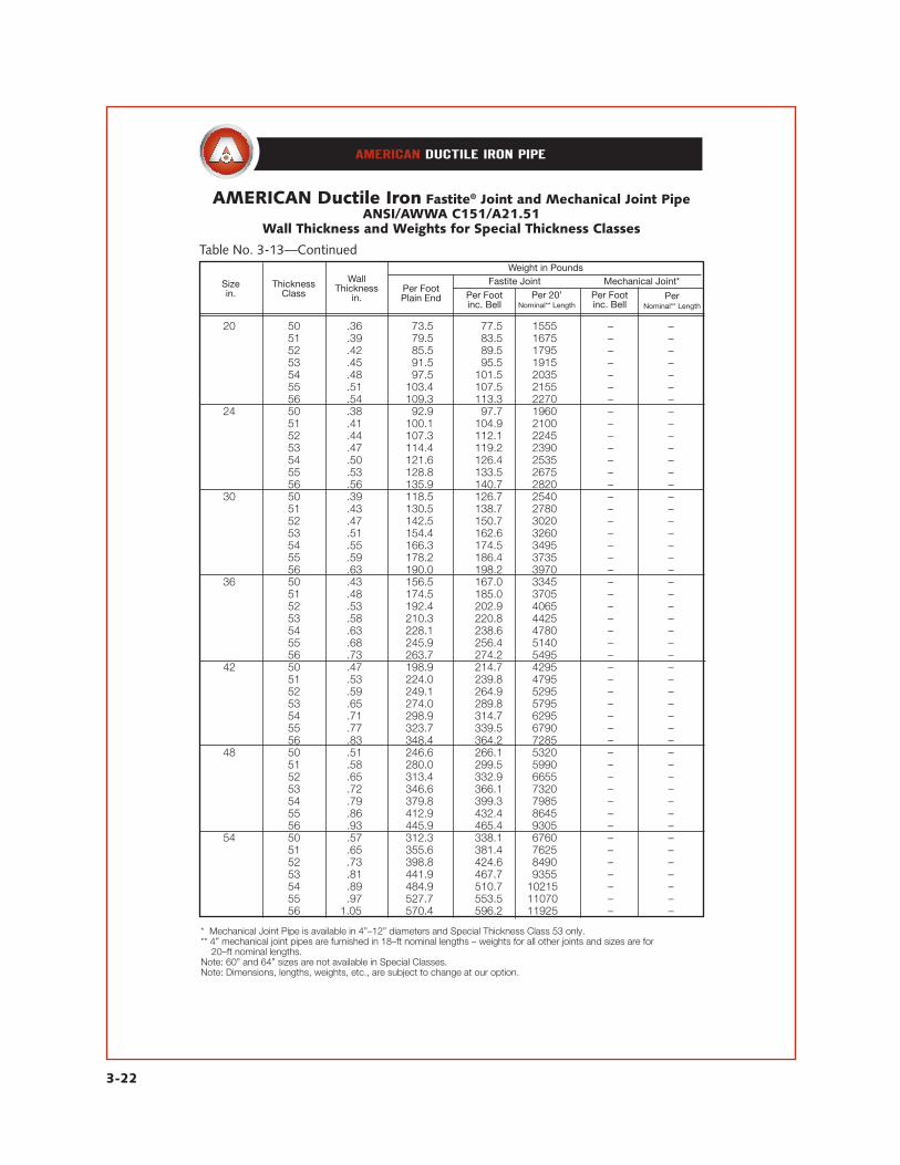
AMERICAN Ductile Iron Fastite® Joint and Mechanical Joint PipeANSI/AWWA C151/A21.51
Wall Thickness and Weights for Special Thickness Classes
Table No. 3-13—Continued
Sizein.
ThicknessClass
WallThickness
in.Per FootPlain End Per Foot
inc. BellPer 20’
Nominal** LengthPer Footinc. Bell
PerNominal** Length
Weight in PoundsFastite Joint Mechanical Joint*
20 50 .36 173.5 177.5 1555 – – 51 .39 179.5 183.5 1675 – – 52 .42 185.5 189.5 1795 – –1 53 .45 191.5 195.5 1915 – – 54 .48 197.5 101.5 2035 – – 55 .51 103.4 107.5 2155 – – 56 .54 109.3 113.3 2270 – – 24 50 .38 192.9 197.7 1960 – – 51 .41 100.1 104.9 2100 – – 52 .44 107.3 112.1 2245 – – 53 .47 114.4 119.2 2390 – – 54 .50 121.6 126.4 2535 – – 55 .53 128.8 133.5 2675 – – 56 .56 135.9 140.7 2820 – – 30 50 .39 118.5 126.7 2540 – – 51 .43 130.5 138.7 2780 – – 52 .47 142.5 150.7 3020 – – 53 .51 154.4 162.6 3260 – – 54 .55 166.3 174.5 3495 – – 55 .59 178.2 186.4 3735 – – 56 .63 190.0 198.2 3970 – – 36 50 .43 156.5 167.0 3345 – – 51 .48 174.5 185.0 3705 – – 52 .53 192.4 202.9 4065 – – 53 .58 210.3 220.8 4425 – – 54 .63 228.1 238.6 4780 – – 55 .68 245.9 256.4 5140 – – 56 .73 263.7 274.2 5495 – – 42 50 .47 198.9 214.7 4295 – – 51 .53 224.0 239.8 4795 – – 52 .59 249.1 264.9 5295 – – 53 .65 274.0 289.8 5795 – – 54 .71 298.9 314.7 6295 – – 55 .77 323.7 339.5 6790 – – 56 .83 348.4 364.2 7285 – – 48 50 .51 246.6 266.1 5320 – – 51 .58 280.0 299.5 5990 – – 52 .65 313.4 332.9 6655 – – 53 .72 346.6 366.1 7320 – – 54 .79 379.8 399.3 7985 – – 55 .86 412.9 432.4 8645 – – 56 .93 445.9 465.4 9305 – – 54 50 .57 312.3 338.1 6760 – – 51 .65 355.6 381.4 7625 – – 52 .73 398.8 424.6 8490 – – 53 .81 441.9 467.7 9355 – – 54 .89 484.9 510.7 10215 – – 55 .97 527.7 553.5 11070 – – 56 1.05 570.4 596.2 11925 – –
* Mechanical Joint Pipe is available in 4”–12” diameters and Special Thickness Class 53 only.** 4” mechanical joint pipes are furnished in 18–ft nominal lengths – weights for all other joints and sizes are for 20–ft nominal lengths.Note: 60” and 64” sizes are not available in Special Classes.Note: Dimensions, lengths, weights, etc., are subject to change at our option.
3-23
Ductile Iron Pipe for Gravity Flow Service
Due to its high strength and stiffness with the resulting ability to support heavy earth and other type external loads, ductileiron pipe has found wide acceptance in gravity flow service such as sewer lines, out-falls and culvert pipe. The problems of infiltration, root intru-sion, and leakage are eliminated in sewer service with the use of the Fastite joint. The resistance of ductile iron to impact, the con-venient pipe lengths, and the ease of assem-bly represent additional advantages of using ductile iron pipe in sewer service. In addi-tion, ductile iron pipe has an inside diametergreater than nominal pipe size which results in greater flow capacity with potential cost savings. Ductile iron pipe is available for normal domestic sewage service with ce-ment lining. Other linings are available for sewer and special services. See Section 11.
Ductile Iron Culvert PipeASTM A716 ASTM A716 is the standard for Ductile Iron Culvert Pipe covering sizes 14” through 64” manufactured per ANSI/AWWA C151/A21.51. AMERICAN Ductile Iron Culvert Pipe is furnished with Fastite or other suit-able joints and is coated inside and outside with an asphaltic coating approximately 1 mil thick; or may be cement lined. Minimum pressure classes are shown in this standard for sizes 14” through 64” for the range of cover from 2 to 41 feet, depending on size, based on Type 5 trench condition. This is the same Type 5 laying condition shown in current AWWA Stan-
dards C150 and C151. See Fig. 3-2. Pipe thickness for other conditions can be calcu-lated by using formulas and design criteria in AWWA C150, except with modifications as specified in A716.
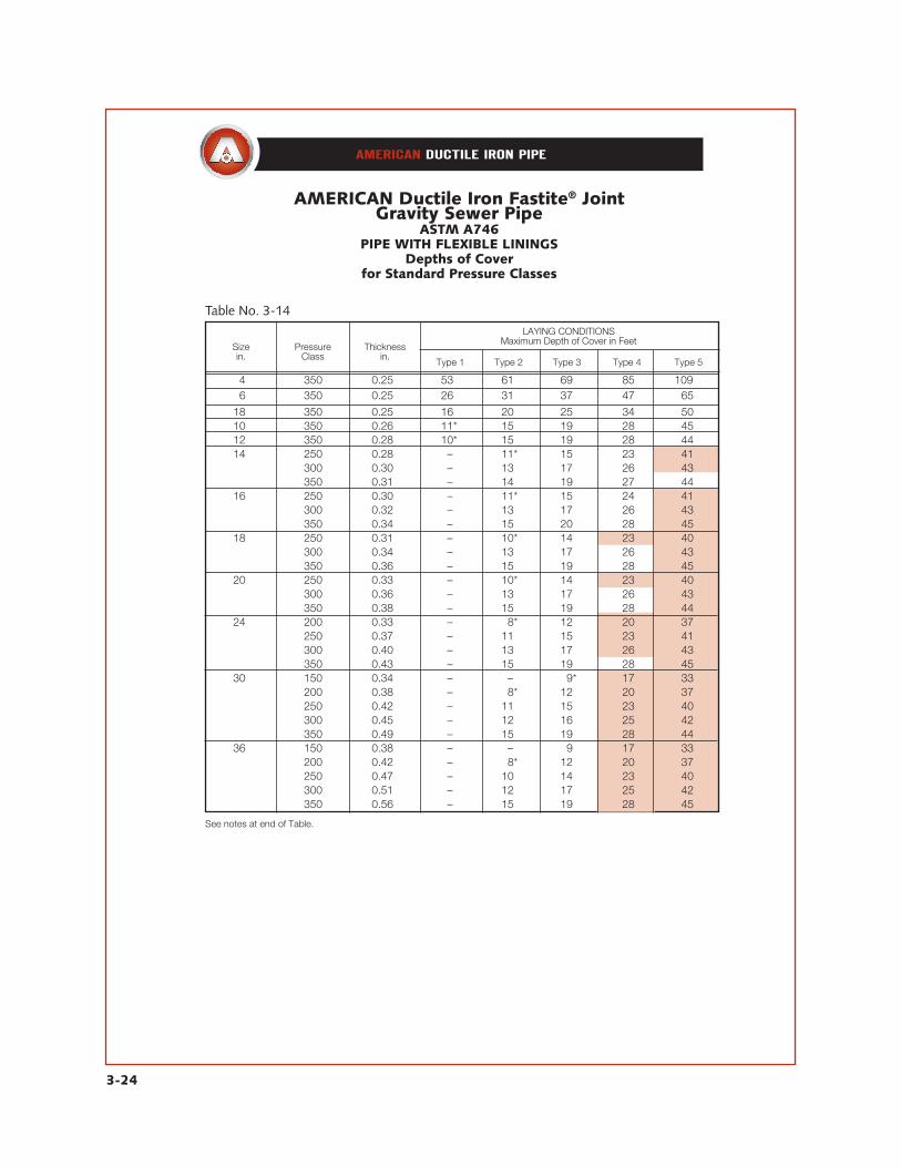
Ductile Iron Gravity Sewer PipeASTM A746 ASTM A746 is the standard for Ductile Iron Gravity Sewer Pipe in sizes 4” through 64” with Fastite Joints. The design of AMERICAN Ductile Iron Gravity Sewer Pipe in this standard is based on the same formulas and design criteria as pipe designed per ANSI/AWWA C150/A21.50, except that pipe with a flexible lin-ing is designed with maximum allowable deflection of 5% of the outside diameter of the pipe instead of 3%. In the A746 Stan-dard are thickness tables for Cement-lined pipe and for Flexible-lined pipe. The thicknesses for Cement-lined pipe will be the same as those in AWWA C151 for the same depths of cover and lay-ing conditions. See Table No. 3-11. Table No. 3-14 shows depths of cover for the different laying conditions for 4” through 64” Pressure Classes of Flexible-lined pipe. The shaded areas indicate the depths of cover which are different from Cement-lined pipe per A746 and from AWWA C151 as shown in Table No. 3-11. These depths of cover are controlled by design deflection (instead of ring bend-ing stress) and are greater than those for Cement-lined pipe due to the 5% design deflection.
3-24
AMERICAN Ductile Iron Fastite® JointGravity Sewer Pipe
ASTM A746PIPE WITH FLEXIBLE LININGS
Depths of Coverfor Standard Pressure Classes
14 350 0.25 53 61 69 85 109 16 350 0.25 26 31 37 47 65
18 350 0.25 16 20 25 34 50 10 350 0.26 11* 15 19 28 45 12 350 0.28 10* 15 19 28 44 14 250 0.28 – 11* 15 23 41 300 0.30 – 13 17 26 43 350 0.31 – 14 19 27 44 16 250 0.30 – 11* 15 24 41 300 0.32 – 13 17 26 43 350 0.34 – 15 20 28 45 18 250 0.31 – 10* 14 23 40 300 0.34 – 13 17 26 43 350 0.36 – 15 19 28 45 20 250 0.33 – 10* 14 23 40 300 0.36 – 13 17 26 43 350 0.38 – 15 19 28 44 24 200 0.33 – 18* 12 20 37 250 0.37 – 11 15 23 41 300 0.40 – 13 17 26 43 350 0.43 – 15 19 28 45 30 150 0.34 – – 19* 17 33 200 0.38 – 18* 12 20 37 250 0.42 – 11 15 23 40 300 0.45 – 12 16 25 42 350 0.49 – 15 19 28 44 36 150 0.38 – – 19 17 33 200 0.42 – 18* 12 20 37 250 0.47 – 10 14 23 40 300 0.51 – 12 17 25 42 350 0.56 – 15 19 28 45
Table No. 3-14
Sizein.
PressureClass
Thicknessin.
LAYING CONDITIONSMaximum Depth of Cover in Feet
Type 1 Type 2 Type 3 Type 4 Type 5
See notes at end of Table.

3-25
AMERICAN Ductile Iron Fastite® JointGravity Sewer Pipe
ASTM A746PIPE WITH FLEXIBLE LININGS
Depths of Coverfor Standard Pressure Classes
42 150 0.41 – – 19 16 32 200 0.47 – 18 12 20 37 250 0.52 – 10 14 23 40 300 0.57 – 12 17 25 42 350 0.63 – 15 19 28 45 48 150 0.46 – – 19 17 33 200 0.52 – 18 12 20 37 250 0.58 – 10 14 23 40 300 0.64 – 12 17 25 42 350 0.70 – 15 19 28 44 54 150 0.51 – – 19 17 33 200 0.58 – 18 12 20 37 250 0.65 – 10 14 23 40 300 0.72 – 13 17 25 43 350 0.79 – 15 19 28 45 60 150 0.54 – 15* 19 17 33 200 0.61 – 18 12 20 37 250 0.68 – 10 14 23 40 300 0.76 – 13 17 25 43 350 0.83 – 15 19 28 45 64 150 0.56 – 15* 19 17 33 200 0.64 – 18 12 20 36 250 0.72 – 10 15 23 40 300 0.80 – 13 17 25 43 350 0.87 – 15 19 28 45
Table No. 3-14—Continued
Sizein.
PressureClass
Thicknessin.
LAYING CONDITIONSMaximum Depth of Cover in Feet
Type 1 Type 2 Type 3 Type 4 Type 5
*Minimum allowable depth of cover is 3’. The shaded areas denote the depths of cover resulting from the pipe thickness being governed by deflection in the design; these covers are greater due to the design deflection of 5% for flexible–lined pipe instead of 3% for cement–lined pipe.
3-26
AMERICAN Ductile Iron PipeTapping and Cutting
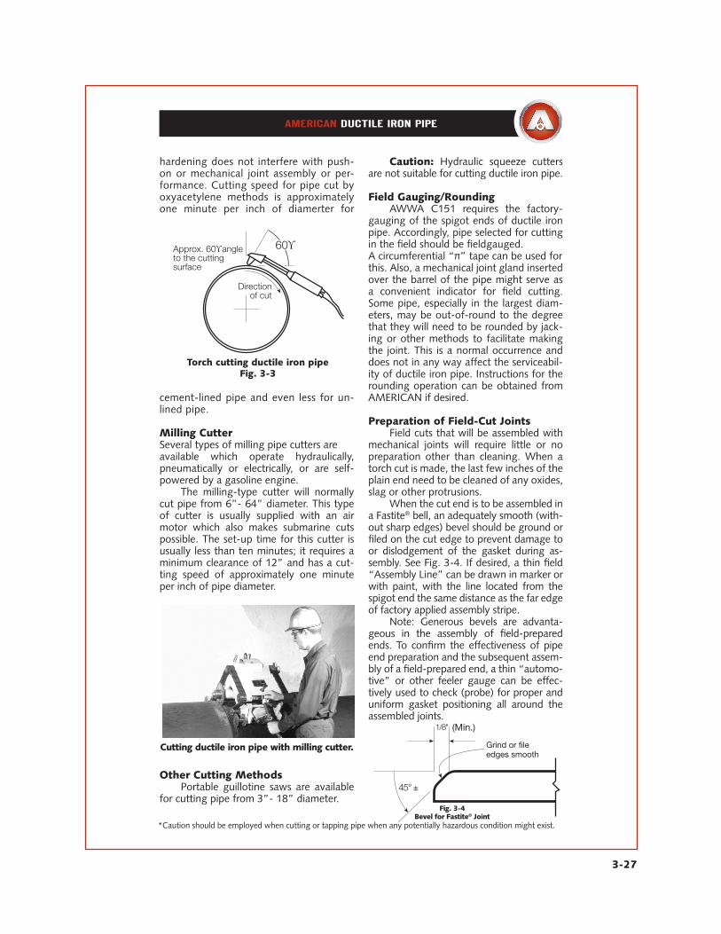
TAPPING* DUCTILE IRON PIPE AMERICAN Ductile Iron pipe is readilytapped either dry or under pressure by using conventional tapping equipment utilized by most contractors and water utilities. Taps made directly into the pipe result in clean, sharp, strong threads, making tap-ping saddles unnecessary for small diameter taps. Teflon tape or a commercial thread compound which is suitable to the service is recommended to be used on threads.
CUTTING* DUCTILE IRON PIPE AMERICAN Ductile Iron pipe is easily cut in the field by several methods, the most common being as follows:
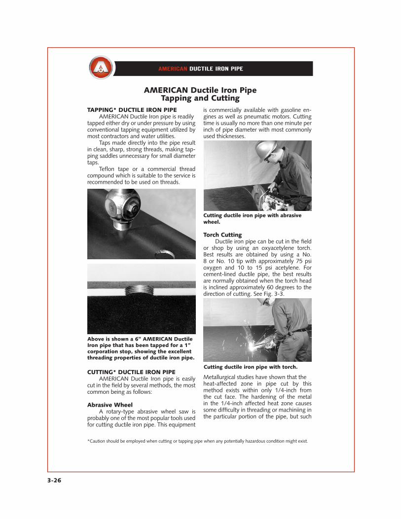
Abrasive Wheel A rotary-type abrasive wheel saw is probably one of the most popular tools used for cutting ductile iron pipe. This equipment
is commercially available with gasoline en-gines as well as pneumatic motors. Cutting time is usually no more than one minute per inch of pipe diameter with most commonly used thicknesses.
Cutting ductile iron pipe with abrasivewheel.
Torch Cutting Ductile iron pipe can be cut in the field or shop by using an oxyacetylene torch. Best results are obtained by using a No. 8 or No. 10 tip with approximately 75 psi oxygen and 10 to 15 psi acetylene. For cement-lined ductile pipe, the best results are normally obtained when the torch head is inclined approximately 60 degrees to the direction of cutting. See Fig. 3-3.
Metallurgical studies have shown that theheat-affected zone in pipe cut by this method exists within only 1/4-inch from the cut face. The hardening of the metal in the 1/4-inch affected heat zone causes some difficulty in threading or machiniing in the particular portion of the pipe, but such
*Caution should be employed when cutting or tapping pipe when any potentially hazardous condition might exist.
Above is shown a 6” AMERICAN DuctileIron pipe that has been tapped for a 1”corporation stop, showing the excellentthreading properties of ductile iron pipe.
Cutting ductile iron pipe with torch.
3-27
hardening does not interfere with push-on or mechanical joint assembly or per-formance. Cutting speed for pipe cut by oxyacetylene methods is approximately one minute per inch of diamerter for
cement-lined pipe and even less for un-lined pipe.
Milling CutterSeveral types of milling pipe cutters areavailable which operate hydraulically, pneumatically or electrically, or are self-powered by a gasoline engine. The milling-type cutter will normally cut pipe from 6”- 64” diameter. This type of cutter is usually supplied with an air motor which also makes submarine cuts possible. The set-up time for this cutter is usually less than ten minutes; it requires a minimum clearance of 12” and has a cut-ting speed of approximately one minute per inch of pipe diameter.
Other Cutting Methods Portable guillotine saws are available for cutting pipe from 3”- 18” diameter.
Caution: Hydraulic squeeze cutters are not suitable for cutting ductile iron pipe.
Field Gauging/Rounding AWWA C151 requires the factory-gauging of the spigot ends of ductile iron pipe. Accordingly, pipe selected for cutting in the field should be fieldgauged.A circumferential “π” tape can be used forthis. Also, a mechanical joint gland inserted over the barrel of the pipe might serve as a convenient indicator for field cutting. Some pipe, especially in the largest diam-eters, may be out-of-round to the degree that they will need to be rounded by jack-ing or other methods to facilitate making the joint. This is a normal occurrence and does not in any way affect the serviceabil-ity of ductile iron pipe. Instructions for the rounding operation can be obtained from AMERICAN if desired.
Preparation of Field-Cut Joints Field cuts that will be assembled with mechanical joints will require little or no preparation other than cleaning. When a torch cut is made, the last few inches of theplain end need to be cleaned of any oxides,slag or other protrusions. When the cut end is to be assembled in a Fastite® bell, an adequately smooth (with-out sharp edges) bevel should be ground or filed on the cut edge to prevent damage to or dislodgement of the gasket during as-sembly. See Fig. 3-4. If desired, a thin field “Assembly Line” can be drawn in marker or with paint, with the line located from the spigot end the same distance as the far edge of factory applied assembly stripe. Note: Generous bevels are advanta-geous in the assembly of field-prepared ends. To confirm the effectiveness of pipe end preparation and the subsequent assem-bly of a field-prepared end, a thin “automo-tive” or other feeler gauge can be effec-tively used to check (probe) for proper and uniform gasket positioning all around the assembled joints.
*Caution should be employed when cutting or tapping pipe when any potentially hazardous condition might exist.
Torch cutting ductile iron pipeFig. 3-3
Cutting ductile iron pipe with milling cutter.
Fig. 3-4Bevel for Fastite® Joint
Grind or fileedges smooth
(Min.)

3-28
AMERICAN Ductile Iron PipeOutlets
Welded-on outlets for flanged, mechani-cal joint, Fastite and restrained jointconnections are furnished for optimumdesign, installation and economy. SeeSection 7.
Outlet/Tapping Saddles provide aneffective, field adaptable, and economi-cal means of making connection to apipeline, either during construction orwhile under pressure. Saddles are avail-able with flanged or mechanical jointoutlet for use on pipe sizes 16” through54”. See Section 7.

12 148 108 48 14 12
3-29
AMERICAN Ductile Iron PipeStacking
Loading
Approximate Loading QuantitiesMinimum Pressure Classes ofFastite Joint Ductile Iron Pipe
Suggested Maximum Allowable Stacking HeightsTable No. 3-15
Pipe Sizein.
Number ofTiers
Pipe Sizein.
Number ofTiers
14 *16 24 5 16 *13 30 4 18 *11 36 4 10 *10 42 3 12 *9 48 3 14 *8 54 3 16 7 60 2 18 6 64 2 20 6 – –
*Stacking heights are limited by practical consideration to a heightof approximately 12 feet for purposes of safety and handling ease.
Table No. 3-15
Pipe Sizein.
No. of Nominal Lengths
Truckload Carload
No. of Nominal Lengths
Truckload CarloadPipe Size
in.
14 153 459 24 18 27 16 108 288 30 12 27 18 181 216 36 18 12 10 163 126 42 18 12
14 140 175 54 14 12 16 135 160 60 12 12 18 132 148 64 12 12 20 126 148 – – –
It is recommended that pipe to be stored for any extended period of time should not be stacked higher than indi-cated in the table below. To prevent dirt and debris from entering the pipe, bot-tom tiers should be kept off the ground on timbers, rails, or concrete supports.
Pipe on succeeding tiers should be alternated — bell-plain end, plain end-bell, etc. Timbers 4” X 4” size should be placed between each tier and chocks nailed at each end to prevent movement of the pipe. For safety and convenience, each size should be stacked separately.
Ductile iron pipe is normally shippedin truckload or carload lots for freight economies. Tabulated below are practicalloading quantities for minimum classes, Fastite Joint ductile iron cement-lined pipe. Truckload quantities are based on standard 40,000-lb loading.
Quantities can vary due to chang-es in joints, classes, ICC tariff, linings, weights, dunnage, other material or sizes included in loads, etc. Therefore, this ta-ble should be used as a guide only. Check AMERICAN if more exact information is required.

3-30
Other AMERICAN Joints
AMERICAN Fastite® Joint with Fast-Grip® Gasket, 4”-30”
The AMERICAN Fast-Grip Gasket furnished in sizes 4”-30” provides flexible, field-adaptable joint restraint in a standard AMERICAN Fastite (or Flex-Ring) Bell. See Sections 4 and 9.
AMERICAN Flex-Ring® Joint, 4”-12”
The AMERICAN Flex-Ring Joint provides flexible joint restraint against thrust dueto internal water working pressure or external forces. It is also used in horizontaldirectional drilling (HDD) and pipe bursting applications. See Sections 4 and 9.
AMERICAN Flex-Ring® Joint, 14”-48”
The AMERICAN Flex-Ring Joint provides flexible joint restraint against thrust dueto internal water working pressure or external forces. See Section 9.
3-31
AMERICAN Joints forPipe and Fittings
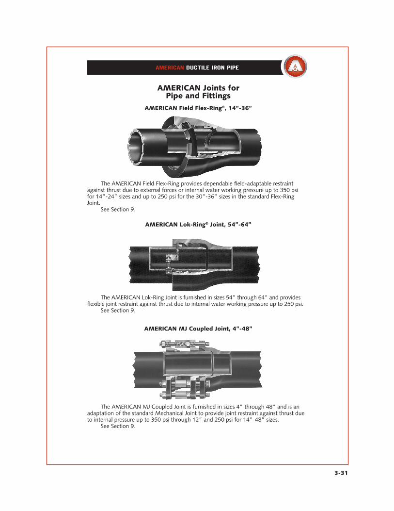
AMERICAN Field Flex-Ring®, 14”-36”
The AMERICAN Field Flex-Ring provides dependable field-adaptable restraintagainst thrust due to external forces or internal water working pressure up to 350 psifor 14”-24” sizes and up to 250 psi for the 30”-36” sizes in the standard Flex-RingJoint. See Section 9.
AMERICAN Lok-Ring® Joint, 54”-64”
The AMERICAN Lok-Ring Joint is furnished in sizes 54” through 64” and providesflexible joint restraint against thrust due to internal water working pressure up to 250 psi. See Section 9.
AMERICAN MJ Coupled Joint, 4”-48”
The AMERICAN MJ Coupled Joint is furnished in sizes 4” through 48” and is anadaptation of the standard Mechanical Joint to provide joint restraint against thrust dueto internal pressure up to 350 psi through 12” and 250 psi for 14”-48” sizes. See Section 9.
3-32
AMERICAN Joints for Pipe and Fittings
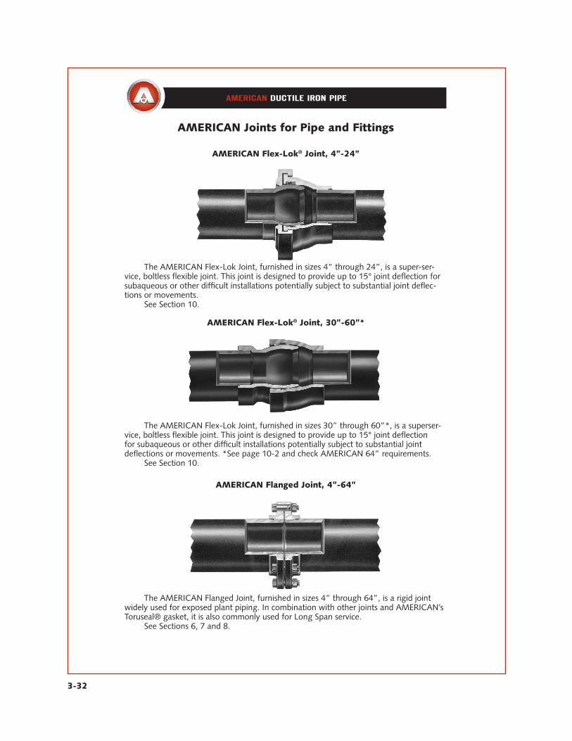
AMERICAN Flex-Lok® Joint, 4”-24”
The AMERICAN Flex-Lok Joint, furnished in sizes 4” through 24”, is a super-ser-vice, boltless flexible joint. This joint is designed to provide up to 15° joint deflection for subaqueous or other difficult installations potentially subject to substantial joint deflec-tions or movements. See Section 10.
AMERICAN Flex-Lok® Joint, 30”-60”*
The AMERICAN Flex-Lok Joint, furnished in sizes 30” through 60”*, is a superser-vice, boltless flexible joint. This joint is designed to provide up to 15° joint deflectionfor subaqueous or other difficult installations potentially subject to substantial jointdeflections or movements. *See page 10-2 and check AMERICAN 64” requirements. See Section 10.
AMERICAN Flanged Joint, 4”-64”
The AMERICAN Flanged Joint, furnished in sizes 4” through 64”, is a rigid jointwidely used for exposed plant piping. In combination with other joints and AMERICAN’sToruseal® gasket, it is also commonly used for Long Span service. See Sections 6, 7 and 8.
3-33
AMERICAN Joints for Pipe and Fittings
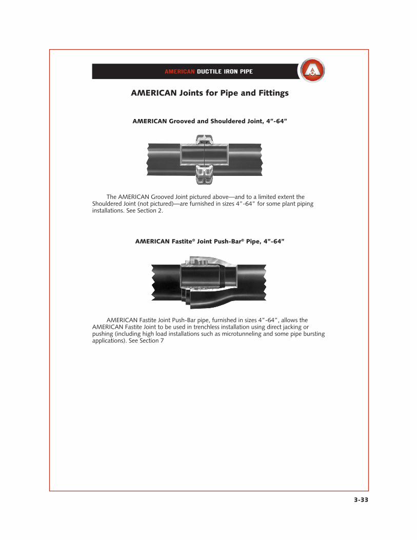
AMERICAN Grooved and Shouldered Joint, 4”-64”
The AMERICAN Grooved Joint pictured above—and to a limited extent theShouldered Joint (not pictured)—are furnished in sizes 4”-64” for some plant pipinginstallations. See Section 2.
AMERICAN Fastite® Joint Push-Bar® Pipe, 4”-64”
AMERICAN Fastite Joint Push-Bar pipe, furnished in sizes 4”-64”, allows theAMERICAN Fastite Joint to be used in trenchless installation using direct jacking orpushing (including high load installations such as microtunneling and some pipe burstingapplications). See Section 7
AMERICAN reserves the right to modify or change designs, materials, specifications, or dimensions shown herein without prior notice.
This is a preprint of a section from the 19th Edition of the AMERICAN Pipe Manual. References may be made in this section to other sections of this manual.
APM3—REV—06-07
AMERICAN DUCTILE IRON PIPE
®
Related Documents