HEATING VENTILATING AND AIR CONDITIONING 230000 - 1 10/2021 Environmental Systems Upgrades- SISD Aquatic Center Socorro Independent School District SECTION 230000 - HEATING, VENTILATING AND AIR CONDITIONING PART 1 - GENERAL 1.1 CONTENTS A. This section of the specifications contains items applicable only to the Heating, Ventilating and Air conditioning system. Section 22 05 00, Mechanical General Conditions and Section 22 07 00, Insulation for Mechanical Systems, contains items which also apply. This section of the specifications supplements and modifies some of the statements herein as to apply specifically to the heating, ventilating and air conditioning system. 1.2 SCOPE A. It is the intent of these specifications and drawings to furnish a heating, ventilating and air conditioning system inside and outside of the building, complete, fully adjusted and ready to use. All work and material must conform to all State and Local Codes in every respect. PART 2 - PRODUCTS 2.1 INSULATION A. Insulation shall be as specified in Section 22 07 00, Insulation for Mechanical Systems. 2.2 VALVES A. Valves shall be as specified in Section 22 05 00 Mechanical General Conditions. 2.3 SHEET METAL A. All ductwork shall be fabricated and installed so that no undue vibration or noise results. All joints shall be airtight with additional caulking provided if necessary. Ducts shall be constructed of the best grade galvanized mild steel sheets with joints and reinforcing in accordance with the recommended construction as listed in the current edition of HVAC Metal Duct Construction Standards - SMACNA. Ductwork installed between outlet of air handling units and terminal units shall be constructed to 4 “ water gage pressure class and sealed to class A sealing requirements. Ductwork downstream of terminal units, fan coil units, evaporative coolers, rooftop air conditioning units, make up air units, and downstream of exhaust fans shall be constructed to 1” water gage pressure class and sealed to class B sealing requirements. Hang ducts with straps attached to bottom of ducts spaced in accordance with SMACNA Standards. Curved elbows, if used, shall have a center line radius equal to 1-1/2 times the duct width. Square elbows shall have turning vanes equal to HEP Aerodyne Co. ducturns. Job fabricated vanes will not be accepted without prior approval. B. Provide all necessary dampers as required for proper adjustment and control of air distribution. Provide volume extractors similar to Metalaire Airtrol extractors set at 20 degrees at all branches in ductwork where other means of control are not indicated or used, and in ductwork behind sidewall supply registers. All damper rods shall be marked to indicate the relative position of the damper lade with respect to rod. C. Provide one inch (1") angle collars for all exposed ducts passing through walls, ceiling or floors. Anchor collars in position after installation is complete.

Welcome message from author
This document is posted to help you gain knowledge. Please leave a comment to let me know what you think about it! Share it to your friends and learn new things together.
Transcript

HEATING VENTILATING AND AIR CONDITIONING 230000 - 1
10/2021 Environmental Systems Upgrades- SISD Aquatic Center Socorro Independent School District
SECTION 230000 - HEATING, VENTILATING AND AIR CONDITIONING
PART 1 - GENERAL
1.1 CONTENTS
A. This section of the specifications contains items applicable only to the Heating, Ventilating and
Air conditioning system. Section 22 05 00, Mechanical General Conditions and Section 22 07 00, Insulation for Mechanical Systems, contains items which also apply. This section of the specifications supplements and modifies some of the statements herein as to apply specifically to the heating, ventilating and air conditioning system.
1.2 SCOPE
A. It is the intent of these specifications and drawings to furnish a heating, ventilating and air
conditioning system inside and outside of the building, complete, fully adjusted and ready to use. All work and material must conform to all State and Local Codes in every respect.
PART 2 - PRODUCTS
2.1 INSULATION
A. Insulation shall be as specified in Section 22 07 00, Insulation for Mechanical Systems.
2.2 VALVES
A. Valves shall be as specified in Section 22 05 00 Mechanical General Conditions.
2.3 SHEET METAL
A. All ductwork shall be fabricated and installed so that no undue vibration or noise results. All
joints shall be airtight with additional caulking provided if necessary. Ducts shall be constructed of the best grade galvanized mild steel sheets with joints and reinforcing in accordance with the recommended construction as listed in the current edition of HVAC Metal Duct Construction Standards - SMACNA. Ductwork installed between outlet of air handling units and terminal units shall be constructed to 4 “ water gage pressure class and sealed to class A sealing requirements. Ductwork downstream of terminal units, fan coil units, evaporative coolers, rooftop air conditioning units, make up air units, and downstream of exhaust fans shall be constructed to 1” water gage pressure class and sealed to class B sealing requirements. Hang ducts with straps attached to bottom of ducts spaced in accordance with SMACNA Standards. Curved elbows, if used, shall have a center line radius equal to 1-1/2 times the duct width. Square elbows shall have turning vanes equal to HEP Aerodyne Co. ducturns. Job fabricated vanes will not be accepted without prior approval.
B. Provide all necessary dampers as required for proper adjustment and control of air distribution.
Provide volume extractors similar to Metalaire Airtrol extractors set at 20 degrees at all branches in ductwork where other means of control are not indicated or used, and in ductwork behind sidewall supply registers. All damper rods shall be marked to indicate the relative position of the damper lade with respect to rod.
C. Provide one inch (1") angle collars for all exposed ducts passing through walls, ceiling or floors.
Anchor collars in position after installation is complete.

HEATING VENTILATING AND AIR CONDITIONING 230000 - 2
10/2021 Environmental Systems Upgrades- SISD Aquatic Center Socorro Independent School District
D. Provide flexible connection at inlet and discharge connections of fans and air handling equipment
to prevent mechanical noises from being transmitted to connecting ductwork. Use flexible connection similar and equal to "Ventfab".
E. Install hinged doors on ductwork and housing to provide access to all parts of every automatic
damper, fire damper and all other items requiring maintenance or inspection. Access doors shall be 18" X 12" if permitted by duct size, and if not, shall be as large as possible. All access panels shall have sponge rubber gaskets cemented in place with cam lock closures.
F. Shop Drawings shall be submitted on all items of sheet metal work specified herein. Shop Drawings
of ductwork at air units shall be submitted at a minimum scale of 3/8" equal to one foot.
G. Shop Drawings shall be submitted on all other ductwork. Shop Drawings shall indicate location of all
supply, return, exhaust and light fixtures from the approved reflected ceiling plans.
H. Provide sample drives, duct and guage thickness, and reinforcing requirements for Engineers approval.
2.4 SPIRAL/ OVAL DUCT AND FITTINGS
A. Spiral wound round and oval duct shall be made of galvanized steel. Spiral wound duct shall be manufactured in accordance with the latest editions of SMACNA, ASHRAE and SPIDA Standards.
B. All round and/or flat oval spiral duct and fittings shall be manufactured by a company whose
primary business is the manufacture of spiral duct and fittings...
C. All spiral duct and fittings shall be manufactured from G-60 galvanized steel meeting ASTM
A924 and A653 requirements.
D. Branch connections shall be made with 90º conical and 45º straight taps as shown on the
drawings. All branch connections shall be made as a separate fitting. Factory or field installation
of taps into spiral duct shall not be allowed without written approval of the engineer.
E. 90º and 45º elbows in diameters 3" round through 12" round shall be stamped or pleated elbows.
All other elbows shall be of the gored type. Where it is necessary to use two-piece mitered
elbows. All field joints for round duct up to and including 36" diameter and oval duct up to and
including 41” major axis shall be made with a 2" slip-fit or slip coupling. Diameters 38" round
and larger shall be provided with AccuFlange, or equal, flanged connections. AccuFlange, or
equal, flanged connections may also be used in lieu of slip connections on smaller sizes.
F. Access doors shall be supplied by the duct manufacturer at all fire and/or smoke dampers.
G. All exposed duct shall be double wall, acoustically insulated round/oval duct shall be supplied.
Double wall duct shall be constructed of an outer shell, a 1" thick layer of fiberglass insulation
and an inner metal liner. Insulation shall have a thermal conductivity "K" factor of .26 BTU/hr/sq.
ft./ºF or less.The inner metal liner for all spiral and longitudinal seam duct shall be perforated
metal. All fittings from fan discharge to a point where 35 lineal feet of spiral duct has been used
shall have a perforated metal liner. All other fittings shall have a solid metal liner, which may be
one even gauge lighter than that shown for perforated liners
H. Spiral duct shall be as manufactured by Sisneros Brothers, Spiral pipe of Texas, United McGill,
Duct Direct or approved equal.

HEATING VENTILATING AND AIR CONDITIONING 230000 - 3
10/2021 Environmental Systems Upgrades- SISD Aquatic Center Socorro Independent School District
I. Exhaust duct from fume hoods shall be welded stainless steel.
2.5 FIBERGLASS DUCTBOARD
A. Fiberglass ductboard shall not be used on this project.
2.6 FLEXIBLE DUCT
A. Flexible duct connectors shall be constructed of galvanized spring-steel-wire helix with a two-ply
airtight inner core; nominal one inch (1") thick fiberglass insulation and vinyl vapor barrier, suitable to two inch (2") water gauge. Medium pressure duct connection to VAV box terminals shall be rated to a minimum 4” water gage. Entire duct assembly shall be listed to UL label and shall be Thermoid, Portoduct Type 1 or equal. Maximum length of each run shall be eight (5') feet and supported without sagging. Flex duct shall be allowed only where indicated on the drawings.
2.7 VIBRATION
A. Ductwork shall be isolated from rotating or reciprocating equipment to which it is attached by
means of a flexible connection. See sheet metal specification elsewhere herein for exact requirements. Equipment base isolators shall be provided where detailed on the drawings for equipment on floors, pads or bases.
2.8 GRILLES, REGISTERS, DIFFUSERS
A. Furnish and install grilles, registers, diffusers and accessories of size and type as indicated on
drawings. All to be as manufactured by Nailor, Metal-Aire, Carnes, Titus, or approved equal. See the schedule on the drawings for type and model.
2.9 EXHAUST FANS
A. Furnish and install roof-mounted exhausters as scheduled on the drawings. Exhaust fans shall be
all aluminum construction, belt-driven as indicated with birdscreen and backdraft dampers unless otherwise noted. Furnish an aluminum prefabricated curb, compatible with the exhauster where indicated. All exhaust fans shall be Acme, Cook, Jenn-Fan, Greenheck, Carnes, or approved equal. See control sequence for interlocks of fans with other equipment.
2.10 FIRE DAMPERS
A. Fire dampers shall be Ruskin dynamic type IBD2 “B” or low profile blade or approved equal.
Furnish and install, at locations shown on the plans, fire dampers instructed and tested in accordance with UL Safety Standard 555. Each fire damper shall have a 1-1/2 hour fire protection rating, 165 degree F. Fusible link, and shall include a UL label in accordance with established UL labeling procedures. Damper Manufacturer’s literature submitted for approval, prior to installation shall include comprehensive performance data developed from testing in accordance with AMCA Standard 500 and shall illustrate pressure drops for all sizes for dampers required at all anticipated air flow rates. Fire damper shall be equipped for vertical or horizontal installation as required by the location shown. Fire dampers shall be installed in wall and floor opening utilizing steel sleeves, angles, other materials, and practices required to provide an installation equivalent to that utilized by the Manufacturer when dampers are tested with UL labeling procedures. Installation shall be in accordance with the Damper Manufacturers

HEATING VENTILATING AND AIR CONDITIONING 230000 - 4
10/2021 Environmental Systems Upgrades- SISD Aquatic Center Socorro Independent School District
instructions. All fire damper shall be approved as stated in SMACNA and the current ASHRAE Guide. Acceptable manufacturers are Ruskin, Nailor, Potoroff, or approved equal.
2.11 AIR CONDITIONING UNITS
A. Furnish and install high efficiency packaged electric cooling with gas heat designed to function as a year-round air conditioning systems. Units shall be completely assembled and tested complete with refrigerant charge and ready to operate.
B. Unit cooling and heating capacities shall be as scheduled. C. Unit compressor shall be welded, fully hermetic with crankcase heater and suitable vibration
isolators. The standard unit shall be capable of operating to 45 degrees F. OAT at published CFMs on cooling cycle. Compressors shall have a 5-year warranty. Compressor shall be equipped with factory installed crank case heater.
D. Indoor and outdoor coils shall be of nonferrous construction with aluminum fins mechanically
bonded to seamless copper tubes with all joints brazed.
E. Indoor air fan shall be forward curved centrifugal, belt-driven with adjustable pitch. Indoor fan
motor shall have permanently lubricated bearings. Outdoor fan shall be of the propeller type,
with direct-driven, totally enclosed, permanently lubricated motor. Fans shall discharge upward.
Unit cabinet shall be constructed of galvanized steel, bonderized and coated with a baked enamel
finish. Cabinet interior shall be insulated with 1/2 inch thick neoprene-coated fiberglass. Cabinet
panels shall be easily removable for service to all operating components. A condensate drain for
the indoor coil shall be provided. F. The cooling service shall be protected with low-pressure switch, loss-of-charge protection, indoor
coil freezestats and current and temperature sensitive overload devices. G. Each of these devices shall be wired through the circuit to prevent compressor restart until reset at
the thermostat. The standard room thermostat shall contain an indicating light designed to illuminate if any safety controls trip out the compressor through the lockout circuit.
H. Units listed in the schedule with heat shall be gas-fired () and heat exchangers shall be aluminized
steel. Combustion shall be induced draft with spark ignition. All units shall have factory installed economizer dampers.
I. Hail guard shall be provided for all condenser coils.
J. All Air Conditioning units shall be Trane, or Carrier.
2.12 BOILERS
A. Boiler for hot water heating system may be forced draft type natural gas-fired. The boiler shall
be copper fin type. The boiler shall be constructed in accordance with ASME requirements for
not less than 160 PSI working pressure but shall operate as a low pressure (60 PSI) water
boiler. Boiler shall be complete with gas burners, water tubes, headers, frame heavy insulation,
heavy gage steel, cabinet, headers, and controls; including EMCS interface and pump control.
Boiler controls shall include electric ignition with 100% safety shut-off, high limit control,
ASME rated (60 psi) relief valve, combination temperature and a pressure gage and low water
cut-off. Gas line shall be provided with manual main gas valve, dual electric gas valves, gas
pressure regulator, and pilot shut-off valve, UL listed. Boiler shall be equipped with electric

HEATING VENTILATING AND AIR CONDITIONING 230000 - 5
10/2021 Environmental Systems Upgrades- SISD Aquatic Center Socorro Independent School District
modulating gas valve. Boiler shall have hot water trim and shall be complete with all
components specified herein and/or required for a complete operating unit. Boiler shall have
capacity not less than shown on the drawings at and elevation of 4000 ft. and shall be installed
in strict accordance with the manufacturer’s recommendations and all applicable codes. Boiler
shall be Raypak, or approved equal.
B. Provide field reports and startup checklist to be submitted to Engineer and Owner.
C. A factory authorized service representative shall test, inspect, and adjust boiler, boiler
components, equipment installation, and perform start-up services.
D. Perform installation and startup checks according to manufacturer’s recommendations.
E. Perform operational test: start units to confirm proper motor rotation and unit operation.
Adjust air-fuel ratio and combustion controls. Test and adjust controls and safeties. Replace
damaged and malfunctioning controls and equipment.
F. Perform burner test: adjust burner to eliminate excess oxygen, carbon dioxide, oxides of
nitrogen, and carbon monoxide in flue gas and to achieve rated combustion efficiency.
G. Adjust initial temperature set points. Set field adjustable switches and circuit breaker trip
ranges as indicated.
H. Prepare a written report that documents the testing procedures and their results.
I. Training shall be provided by factory authorized service representative to train maintenance
personnel on-site to adjust, operate, and maintain boilers. Four training manuals shall be
provided to School District personell during training.
2.13 HYDRONIC SYSTEMS PIPING
A. Hydronic hot water piping shall be type "L" hard drawn copper with wrought copper fittings
and 50 percent tin, 50 percent lead solder joints. At the Contractor's option silver solder may be substituted for 50/50 solder.
B. At the Contractor's option he may use schedule 40 black steel in place of copper pipe. Joints
shall be reamed to full pipe diameter before joining. Joints may be screwed, or if the pipe size is two (2") inches or larger, the joints may be welded at the Subcontractor's option. Welded joints shall be made in accordance with the procedure outlined in the USA Piping Code and each welder shall be certified by the National Certified Pipe Welding Bureau, or by another reputable testing laboratory or agency. The Subcontractor shall use only "Threadolet" or "Weldolet" fittings for intersection welding of branches to mains. Valves and specialties shall have screwed of flanged joints. Piping joints and fittings may be "Victaulic" style 77 or equal.
C. Underground hydronic piping shall be Ferro-therm or Copper-therm preinsulated piping system
by Thermacor or approved equal. 2.14 PUMPS A. The Contractor shall furnish and install pumps as scheduled on the plans. Acceptable
manufacturers are Taco, Armstrong, Paco, Aurora, or approved equal. The pumps shall be single stage, vertical in-line with split coupling design and bronze fitted construction. The pump internals shall be capable of being serviced without disturbing piping connections or motor.
B. The impeller shall be of the enclosed type, dynamically balanced and keyed to the shaft and
secured with a suitable locknut.
C. The pump seal shall be standard single mechanical seal with carbon seal ring and ceramic seat.
D. A replaceable shaft sleeve shall be furnished to cover the wetted area of the shaft under the seal.

HEATING VENTILATING AND AIR CONDITIONING 230000 - 6
10/2021 Environmental Systems Upgrades- SISD Aquatic Center Socorro Independent School District
E. The bearing frame assembly of the pump shall be fitted with regreasable ball bearings equivalent to electric motor bearing standards for quiet operation.
B. A flexible coupler, capable of absorbing torsional vibration shall be employed between the pump
and motor and it shall be equipped with a suitable coupling guard as required. The pump shall be factory tested, thoroughly cleaned and painted with one coat of machinery enamel prior to shipment.
C. Starters shall be magnetic, full voltage, NEMA rated and sized, 3-pole, horsepower rated for the
applied voltage, 120 volt coil, NEMA 1 enclosure, H-O-A maintained selector switch, no momentary contact control devices, running time meter, LED pilot lights, overload relays sized at 125% of actual motor nameplate full load amps or as recommended by the motor manufacturer. Square D class 8536 or approved equal. Starters shall be reversing, non-reversing or 2-speed as indicated. Two speed starters shall be compatible with the motors to be controlled. Minimum size shall be NEMA size 1
2.15 BOILER BREECHING
A. Boiler breeching shall be Type B double wall vent. A minimum of one inch (1”) air space
between the inner and outer walls shall be provided and the stack shall be terminated above the
roof according to all local code requirements. All inner pipe shall be aluminum and outer pipe
shall be galvanized steel. All exposed metal is to be protected by one base coat and one finish
coat of heat and corrosion resistant primer and paint.
2.16 GAGES
A. Gages shall be Trerice model 450 or approved equal with an accuracy of one percent (1%) of the
scale range. The scale shall be of bourdon tube type with a scale range of 0 to 50 PSI or 0 to 100 feet.
2.17 GAGE COCKS AND MANUAL AIR VENTS
A. Gage cocks and manual air vents shall be Bolton 150 or approved equal.
2.18 THERMOMETERS
A. Furnish and install industrial thermometers where shown on the plans. Thermometers shall be
equal to a Trerice model A409 adjustable angle 12” scale or equal with separate well.
2.19 VARIABLE REFRIGERANT FLOW SYSTEM
A. The variable capacity, heat pump heat recovery air conditioning system shall be a Mitsubishi Electric CITY MULTI VRF (Variable Refrigerant Flow) zoning system.
B. The R2-Series system shall consist of a PURY outdoor unit, BC (Branch Circuit) Controller, multiple indoor units, and M-NET DDC (Direct Digital Controls). Each indoor unit or group of indoor units shall be capable of operating in any mode independently of other indoor units or groups. System shall be capable of changing mode (cooling to heating, heating to cooling) with no interruption to system operation. To ensure owner comfort, each indoor unit or group of indoor units shall be independently controlled and capable of changing mode automatically when zone temperature strays 1.8

HEATING VENTILATING AND AIR CONDITIONING 230000 - 7
10/2021 Environmental Systems Upgrades- SISD Aquatic Center Socorro Independent School District
degrees F from set point for ten minutes. The sum of connected capacity of all indoor air handlers shall range from 50% to 150% of outdoor rated capacity.
C. The control system shall consist of a low voltage communication network of unitary
built-in controllers with on-board communications and a web-based operator interface. A
web controller with a network interface card shall gather data from this system and
generate web pages accessible through a conventional web browser on each PC
connected to the network. Operators shall be able to perform all normal operator
functions through the web browser interface. PART 3 - EXECUTION
3.1 WORKMANSHIP
A. All work shall be first-class in every respect and shall be done by mechanics skilled in the trade
involved. Careless and/or sloppy work shall be resolved and replaced properly at the Contractor's expense.
3.2 SCHEDULING OF WORK
A. The Contractor shall be required to confer with the Architect, General Contractor and Owner to
determine a schedule of times at which the various items of work are to be accomplished.
3.3 CONSULTATION WITH OTHER CONTRACTORS
A. Before commencing the work, the Contractor shall consult with the General Contractor and other
Subcontractors and arrive at a thorough understanding as to the location of all equipment, ducts, etc., so that there will be no interference with other work. The time of installation of sleeves, etc. shall be determined by the Contractor. In the event he should fail to have material on the job and such provisions are not made previously with the Gen. Contractor, necessary arrangements shall be made at the expense of the Contractor.
3.4 FILTERS
A. All equipment introducing outside air shall be provided with a set of filters for construction, a set
of filters for test and balance/commissioning, and a final set of filters when commissioning and
test and balance is complete. A fresh set of filters is to be provided following an re-testing of
equipment.
3.5 CLEANING, FLUSHING AND WATER TREATMENT OF WATER SYSTEMS
A. Water circulating Systems shall be thoroughly cleaned before placing in operation to rid
systems of rust, dirt, piping compound, mill scale, oil, grease, any and all other material
foreign to water being circulated.
B. Extreme care shall be exercised during construction to prevent dirt and other foreign
matter from entering the pipe or other parts of systems. Pipe stored on the project shall have open
ends capped and equipment shall have openings fully protected. Before erection, each piece of
pipe, fitting, or valve shall be visually examined and dirt removed.

HEATING VENTILATING AND AIR CONDITIONING 230000 - 8
10/2021 Environmental Systems Upgrades- SISD Aquatic Center Socorro Independent School District
C. At pipe end locations a temporary bypass will be installed. Bypass shall be same size as the
supply and return pipe. Prior to flushing the distribution system, the Contractor shall install the
temporary bypass and a temporary line size strainer between the supply and return pipes.
Contractor shall verify that the isolation valves are open.
D. After the temporary bypasses are installed, the Contractor shall provide and operate one pump
which will cause a velocity of 10 feet per second in the main piping. This pump will be provided
with a shot chemical feeder and a strainer assembly. Pump shall be connected to system at the
point where piping goes into the building from the tunnel. If the pump is electric driven, rather
than engine driven, the Contractor shall provide all temporary electrical disconnects, wiring,
fuses, and other electrical devices that are required for safe operation.
E. Circulation will be started using the temporary pump. A nonhazardous cleaning compound (Entec
324 or approved equal) shall be added using the shot feeder until the concentration level of 20
parts per million is reached. Once this 20 parts per million concentration is reached, circulation
will be maintained for 48 hours. After this period of time, the cleaning water shall be dumped to
the sanitary sewer.
F. The distribution system will then be refilled with city water and circulated with continual bleed
and make-up until the water is certified clean by the water treatment consultant, El Paso
Corrosion, and accepted by the Owner. At the completion of this step an inhibitor shall be
introduced. All waste water shall be dumped into the sanitary sewer system.
G. After the system is certified as clean, the Contractor shall close the valves. The bypass piping
shall be removed as final connections to the building are accomplished.
H. During the flushing procedure, strainers shall be cleaned as often as necessary o remove debris
and, in any event, all strainers shall be cleaned by physically removing the strainer screen from
the body of the strainer at the end of flushing. Replace strainer basket and gasket. Contractor shall
not flush through control valves, coils, etc. Contractor shall provide temporary bypasses at coils
and spool pieces at control valves. Flush the coils individually wasting water to sanitary sewer.
Connect coils and install control valves after flushing.
I. Test samples shall be taken and all tests shall indicate that the entire system has reached a PH,
conductivity, and chemical concentration level as approved by the Owner. Contractor shall
purchase needed chemicals from chemical treatment supplier.
J. Hot Water Heating Systems
1. Hot Water Heating Specifications:
a. Contractor shall provide all chemicals required to maintain the
system for 1 year from final acceptance.
b. During the first two months of operation the contractor shall visit
the site weekly and make appropriate adjustments to maintain the
levels outlined below.
c. Weekly field reports shall be issued to the owner through the
Consultant.
d. After the 2 months, a site visit and adjustment shall be required
monthly.

HEATING VENTILATING AND AIR CONDITIONING 230000 - 9
10/2021 Environmental Systems Upgrades- SISD Aquatic Center Socorro Independent School District
e. Reports shall be sent through the consultant for reviewed
forwarded to the owner.
2. Treatment Program Requirements:
a. Chemical will be a borate buffered nitrite formulation.
b. Following residuals and controls to be maintained:
i. 800-1,000 ppm as sodium nitrite formulation.
ii .5-1.0 ppm active Triazole
iii 9.5-10.0 pH
c. System water will not exhibit a hydrate alkalinity reading.
d. Other chemicals may be prepared but require prior approval from
consultant and owner. 3.6 CLEANING, TESTING AND ADJUSTING
A. The Contractor is cautioned to instruct his mechanics to keep all equipment, ducts an materials
free of foreign materials during installation. Any malfunction of the several system resulting from sand, rocks and other foreign material in the systems shall be corrected at the Contractor's expense. Upon completion of the work, the Contractor shall thoroughly cleanout the several duct system. The Contractor shall take precaution during the cleaning operation to protect his work and the work of all other traces and should any damage be done, he shall remedy or repair it to the complete satisfaction of all concerned, and at no additional cost to the Owner.
B. Functional Tests: Make specific tests of all equipment and materials and portions of this
installation as required herein to prove their condition and performance and any tests as required by any authority having jurisdiction over this type of installation. The Contractor shall adjust all equipment, air quantities, controls and devices, so that all components of the various systems are left in proper working order. As part of this test the entire piping system shall be pressurized to 100 PSI for four (4) hours. These tests must be witnessed by a representative from the Engineer's office. All hydronic piping to be flushed out and chemical added.
3.7 START UP
A. It is the responsibility of the Mechanical Contractor to arrange a minimum two (2) day start-up
program. A factory representative for the Owner, the Engineer, and the Mechanical Contractor
shall be on the site. The purpose of this start-up is to run the system thoroughly and determine
that it is functioning satisfactorily. If for some reason the start-up cannot be completed the
program will be rescheduled and the system will be run to the satisfaction of the Engineer at no
additional cost to the Owner. The entire cost of the start-up program shall be included in the
contract.
B. Contractor shall use attached forms for major pieces of equipment. It is the School Districts
requirement all information be filled in prior to acceptance of project.
3.8 OPERATING AND MAINTENANCE MANUALS:
1. Three binders shall be submitted to mechanical consultant. Consultant shall review and
approve then submit the 3 copies to the owner.
2. Operating and maintenance manuals shall include the following systems:
a. Mechanical systems
b. Plumbing systems

HEATING VENTILATING AND AIR CONDITIONING 230000 - 10
10/2021 Environmental Systems Upgrades- SISD Aquatic Center Socorro Independent School District
c. Fire protection systems
d. Energy/management control systems (EMCS)
3. All components specified and/or scheduled of the above systems shall require O&M
manuals and shall be identified according to the specifications and/or schedule
identification mark/label.
4. Basic information required for O&M manuals:
a. Operating routines and procedures:
Control sequences
Temperature set points
Control diagrams
Ventilation requirements
5. Start-up and shut-down procedures i.e. checklist for start-up/shut-down
a. Equipment/fixture specific information
Identification mark/label
Manufacturer name
Model #
Etc.
b. Trouble shooting section
c. Preventive maintenance program including frequency of actions
d. Scheduled maintenance programs including frequency of actions
e. Parts lists with local vendors (multiple if available)
6. Manuals shall be submitted and approved by mechanical consultant prior to substantial
completion acceptance.
3.9 SHOP DRAWINGS
Submit shop drawings on the following:
1. Spiral Duct, 2. All sheet metal ductwork 3. Flex Duct, 4. Grilles, Registers, Diffusers, 5. Fire Dampers, 6. Exhaust fans, 7. Energy Recovery Ventilators, 8. Air conditioning Units, and 9. VRF systems.
END OF SECTION 23 00 00

COMMON WORK RESULTS FOR MECHANICAL 230500 - 1
10/2021 Environmental Systems Upgrades- SISD Aquatic Center Socorro Independent School District
SECTION 23 05 00 – COMMON WORK RESULTS FOR MECHANICAL
PART 1 - GENERAL 1.1 SCOPE
A. The scope of the work included under this Division of the specifications shall include a complete
mechanical system as shown on the plans and as specified herein. The Architectural General Conditions of these specifications shall form a part and be included under this section of the specifications. The Mechanical Contractor shall provide all supervision, labor, material, equipment, machinery, plant and any and all other items necessary to complete the mechanical system. All other items of equipment are specified in the singular; however, the Mechanical Contractor shall provide and install the number of items of equipment as indicated on the drawings, and as required for complete systems.
B. It shall be noted that work under this section of the specifications includes: Heating, Ventilating
and Air Conditioning, 23 00 00; Mechanical General Conditions, 23 05 00, Insulation for Mechanical Systems, 23 07 00; Test and Balance, 23 05 93;
PART 2 - MATERIALS 2.1 CODES, RULES, PERMITS, FEES
A. The Mechanical Contractor shall give all necessary notices, obtain all permits and pay all
government and state sales taxes, fees, and other costs, including utility connections or extensions, in connection with his work; file all necessary plans, prepare all documents and obtain all necessary approvals of all governmental departments having jurisdiction; obtain all required certificates of inspection for his work and deliver same to the Architect before request for acceptance and final payment for the work. The Mechanical Contractor shall include in the work, without extra cost to the Owner, any labor, materials, services, apparatus, drawings, in order to comply with all applicable laws, ordinances, rules and regulations whether or not shown on drawings and/or specified. Refer to General Conditions for additional information.
B. All materials furnished and all work installed shall comply with the National Fire Codes of the
National Fire Protection Association, with the requirements of all governmental departments having jurisdiction. All materials and equipment for the electrical portion of the mechanical system shall bear the approval label, shall be listed by the Underwriters Laboratories, Inc. and bear the UL label. All mechanical equipment, electrical wiring, and devices shall be in accordance with the National Electric Code (NEC).
2.2 INTENT
A. It is the intention of these specifications and drawings to call for finished work, tested, and ready
for operation. Wherever the word "provide" is used, it shall mean "furnish and install complete and ready for use". Details not usually shown or specified, but necessary for the proper installation and operation, shall be included in the work, the same as if herein specified or shown.
2.3 SURVEYS AND MEASUREMENTS

COMMON WORK RESULTS FOR MECHANICAL 230500 - 2
10/2021 Environmental Systems Upgrades- SISD Aquatic Center Socorro Independent School District
A. The Mechanical Contractor shall base all measurements, both horizontal and vertical from established benchmarks. All work shall agree with these established lines and levels. Verify all measurements at site and check corrections of same as related to the work. Should the Mechanical Contractor discover any discrepancy between actual measurements and those indicated, which prevents following good practice or the intent of the drawings and specifications, he shall notify the Architect, through the General Contractor, and shall not proceed with his work until he has received instructions from the Architect. The Contractor must carefully locate and verify all of the existing utilities to be used as a part of this contract.
2.4 DRAWINGS
A. Drawings are diagrammatic and indicate the general arrangement of systems and work included
in the contract. Drawings are not to be scaled. The architectural drawings and details shall be examined for exact locations of fixtures and equipment. Where they are not definitely located, this information shall be obtained from the Engineer, before he proceeds with the work. The Mechanical Contractor shall follow drawings in laying out work and check drawings of other trades to verify spaces in which work will be installed. Maintain maximum headroom and space conditions at all points. Where headroom or space conditions appear inadequate the Architect shall be notified before proceeding with installation.
2.5 "OR EQUAL"
A. Wherever the words "approved equal", "equal", or words to the same effect are used in
connection with any specified material, it is to be understood that such words mean any material or work of any kind claimed to be an equal in quality to the work or material specified and shall be so approved in writing by the Engineer, except as noted. It is further understood that no material or work shall be presented to the Engineer as work or material equal to that specified without the full understanding on the part of the manufacturers and agents for the so-called "equal" material, and the full understanding on the part of the contractors, that the Engineer is to use his own judgment in the matter; that his decision is final, and that in the event of an adverse condition, no claim of any sort shall be made against the Owner or Architect or Engineer.
2.6 SHOP DRAWINGS
A. The Mechanical Contractor shall submit for approval detailed shop drawings of all equipment and
all material required to complete the project, and no material or equipment may be delivered to the jobsite or installed until the Mechanical Contractor has in his possession the approved shop drawings for the particular material or equipment. The shop drawings shall be complete as described herein. The Mechanical Contractor shall furnish the number of copies required by the General and Special Conditions of the contract, but in no case less than four (4) copies. Prior to delivery of any material to the jobsite, and sufficiently in advance of requirements to allow the Architect ample time for checking, submit for approval: detailed, dimensions, operating clearances, performance characteristics and capacity. Each item of equipment proposed shall be a standard catalog product of an established manufacturer and of equal quality, finish and durability to that specified.
B. The Mechanical Contractor shall submit for approval detailed ductwork and mechanical room
layout shop drawings; showing coordination between disciplines, see above for submission
requiredments.

COMMON WORK RESULTS FOR MECHANICAL 230500 - 3
10/2021 Environmental Systems Upgrades- SISD Aquatic Center Socorro Independent School District
2.7 EQUIPMENT DEVIATIONS
A. Where the Mechanical Contractor proposed to use an item of equipment other than that specified
or detailed on the drawings, which required any redesign of the structure, partitions, foundations, piping, wiring or any other part of the mechanical, electrical or architectural layout, all such redesign, and all new drawings and detailing required therefore, shall be prepared by the Mechanical Contractor at his own expense and approved by the Architect. Where such approved deviation requires a different quantity and arrangement of ductwork, piping, wiring, conduit and equipment from that specified or indicated on the drawings, the Mechanical Contractor shall furnish and install any such ductwork, piping, structural supports, insulation, controllers, motors, starters, electrical wiring and conduit, and any other additional equipment required by the system at no additional cost to the Owner.
2.8 COOPERATION WITH OTHER TRADES
A. The Mechanical Contractor shall give full cooperation to other trades and shall furnish in writing
to the Contractor, with copies to the Architect, any information necessary to permit the work of all trades to be installed satisfactorily and with the least possible interference or delay.
2.9 PROTECTION
A. The Mechanical Contractor shall protect all work and material from damage by his workmen, and
shall be liable for all damage thus caused and replace all damaged materials at no cost to the Owner. The Mechanical Contractor shall be responsible for work and equipment until finally inspected, tested and accepted. He shall protect work against theft, injury or damage, and shall carefully store material and equipment received on-site which is not immediately installed. He shall close open ends of work with temporary covers or plugs during storage and construction to prevent entry of obstructing material.
2.10 SCAFFOLDING, RIGGING, HOISTING
A. The Mechanical Contractor shall furnish all scaffolding, rigging, hoisting and services necessary
for erection and deliver onto the premises any equipment and apparatus furnished. The Contractor will remove the necessary equipment from the premises when no longer required.
2.11 EXCAVATION AND BACKFILLING
A. Mass excavation to approximate building levels will be carried out under a section of the
architectural specifications. The Mechanical Contractor shall; however, do all trench and pit excavation and backfilling required for work under this section of the specifications, inside and outside the building, including repairing of finished surfaces, all required shoring, bracing, pumping and all protection for safety of persons and property. Local or State Safety Codes shall be strictly observed. In addition, it shall be the responsibility of the Mechanical Contractor to check the indicated elevation of the utilities entering and leaving the building. If such elevations require excavations lower than the footing levels, the Architect shall be notified of such conditions and a redesign shall be made before excavations are commenced. It is also the responsibility of the Mechanical Contractor to make the excavations at the minimum required depths in order not to undercut the footing. Filling, backfilling and compaction shall be as specified under the architectural sections of these specifications.

COMMON WORK RESULTS FOR MECHANICAL 230500 - 4
10/2021 Environmental Systems Upgrades- SISD Aquatic Center Socorro Independent School District
B. Backfill may be native material except that all material from six inches (6") below the pipe bottom to six inches above the top of the pipe must pass a 3/4" sieve. If the native material is determined to be too rocky by the Engineer, he may require imported material for pipe bedding.
2.12 MATERIALS AND WORKMANSHIP
A. All materials and apparatus required for the work, except as specifically specified otherwise, shall
be new, of first-class quality, and shall be furnished, delivered, erected, connected and furnished
in every detail, and
shall be so selected and arranged as to fit properly into the building spaces. Where no specific
kind or quality of material is given a first-class standard article as approved by the Architect shall
be furnished. The Mechanical Contractor shall furnish the services of an experienced
superintendent, who shall be constantly in charge of the installation of the work, together with all
skilled workmen, fitters, metal workers, welders, helpers, and labor required to unload, transfer,
erect, connect, adjust, start, operate and test each system.
B. Unless otherwise specifically indicated on the plans or specifications all equipment and materials shall be installed with the approval of the Engineer in accordance with the instructions of the manufacturer. This includes the performance of such tests as the Manufacturer instructs.
2.13 MOTORS
A. Motors shall be built in accordance with the latest standards of NEMA and as specified. Motors
shall be tested in accordance with standard of A.S.A., C50 and conform thereto for insulation resistance and dielectric strength. Provide motors manufactured by General Electric, Westinghouse, Allis Chalmers or Century designed for quiet continuous operation with forty (40) degrees C. rise at full load and rated speed as individually specified. Motors shall be of the same make except those incorporated in package units, and all, including those in package units, shall be provided with ball bearings and conduit connection boxes. Unless stated otherwise, motors 1 HP and smaller shall be suitable for operation of single phase, 60 cycle, and 120 volt current. All motors shall be provided with thermal overload protection. Motors 1 HP or larger shall be either 208 volt or 480 volt, three phase as scheduled. Two speed, three phase motors shall be dual winding.
B. All motor starters shall be provided by the Mechanical Contractor if integral with the equipment.
All three phase magnetic starters shall be furnished with three coil overload protection. All starters which are not integral with the equipment and other electrical control equipment installed in damp, moist or areas of special conditions, shall be designed and approved for the installation.
2.14 QUIET OPERATION AND VIBRATION
A. All work shall operate under all conditions of load without any sound of vibration which is
objectionable in the opinion of the Architect/Engineer. In case of moving machinery, sound or vibration noticeable outside its own room will be considered objectionable. Sound or vibration conditions considered objectionable by the Architect shall be corrected in an approved manner by the Mechanical Contractor at his expense. Vibration control shall be by means of approved vibration eliminators in a manner as recommended by the manufacturer of the eliminators.
2.15 ACCESSIBILITY
A. The Mechanical Contractor shall be responsible for the sufficiency of the size of shafts and
chases, the adequate clearance in double partitions and hung ceilings for the proper installation of

COMMON WORK RESULTS FOR MECHANICAL 230500 - 5
10/2021 Environmental Systems Upgrades- SISD Aquatic Center Socorro Independent School District
his work. The Contractor shall cooperate with the General Contractor and all other contractors whose work is in the same space, and shall advise the General Contractor of his requirements. Such spaces and clearances shall; however, be kept to the minimum size required. The mechanical Contractor shall locate all equipment which must be serviced, operated or maintained in fully accessible positions. Equipment shall include but not be limited to: valves, traps, cleanouts, motors and controllers. If required or better accessibility, any change shall be approved by the Architect. The Mechanical Contractor shall provide the General Contractor the exact locations of access panels for each concealed valve, control, damper or other device requiring service. Access panels not shown in the architectural drawings shall be provided and installed by the Mechanical Contractor and as specified in architectural sections of the specifications. Locations of these panels shall be submitted in sufficient time to be installed in the normal course of work
2.16 FOUNDATIONS, SUPPORTS, PIERS, ATTACHMENTS
A. The Contractor shall furnish and install all necessary foundations, supports, pads and bases
required for all equipment furnished under this contract, unless otherwise noted. All equipment where foundations are indicated, furnish and install concrete pads as shown. All pads shall be extended six inches (6") beyond equipment base in all directions with top edge chamfered. All equipment, unless otherwise shown, shall be securely attached to the building structure in an approved manner. Attachments shall be of a strong and durable nature and any attachments that are, in the opinion of the Architect, not strong enough shall be replaced as directed.
2.17 ELECTRICAL CONNECTIONS
A. The Electrical Contractor shall furnish and install all power wiring except the following when
rated at 25 VAC or less: (1) temperature control wiring; (2) equipment control wiring; and (3) interlocking wiring. The Electrical Contractor shall furnish and install all power wiring complete from power source to motor or equipment junction box, including power wiring through starters. The Electrical Contractor shall furnish and install all starters not factory mounted on equipment or otherwise noted. The Mechanical Contractor shall furnish and install all temperature control wiring, interlock wiring and equipment control wiring of 25 VAC or less for the equipment that he furnishes. The Mechanical Contractor shall furnish a starter to the Electrical Contractor, where scheduled on the drawings or integral with the equipment. The Mechanical Contractor shall provide and be responsible for the heater in all starters that the Mechanical Contractor furnishes.
2.18 CUTTING AND PATCHING
A. The Mechanical Contractor shall be responsible for all framing, cutting and patching necessary to
install the work specified in this section. Patching shall match adjacent surfaces and be performed by qualified workmen approved by the Architect. All work shall be in accordance with the applicable Architectural section of these specifications.
2.19 SLEEVES AND PLATES
A. The Mechanical Contractor shall provide and locate all sleeves and inserts required before the
floors and walls are built, or shall be responsible for the cost of cutting and patching required for pipes where sleeves and inserts were not installed, or where incorrectly located, or where they are to be installed in existing walls. Sleeves shall be provided for all mechanical piping passing through concrete floor slabs, masonry, concrete, tile and gypsum wall construction. Where

COMMON WORK RESULTS FOR MECHANICAL 230500 - 6
10/2021 Environmental Systems Upgrades- SISD Aquatic Center Socorro Independent School District
sleeves are placed in exterior walls below grade, the space between the pipe or conduit and the sleeves shall be sealed with link-seal rubber expansion sealers or equal and be made completely watertight. Sleeves shall be constructed of twenty-four (24) gauge galvanized sheet metal with lock seam joints for all sleeves set in concrete floor slabs terminating flush with the floor. All other sleeves shall be constructed of steel pipe unless otherwise indicated on the drawings.
2.20 ESCUTCHEON PLATES
A. Escutcheon plates shall be provided for all exposed uninsulated pipes and all exposed conduit passing through walls, floors and ceilings. Plates shall be nickel-plated, of the split ring type, sized to match the pipe or conduit. Where plates are provided for pipes passing through sleeves which extend above the floor surface, provide deep recessed plates to conceal the pipe sleeves.
2.21 WATERPROOFING
A. Where any work pierces waterproofing including waterproof concrete, the method of installation
shall be as approved by the Architect before work is done. The Mechanical Contractor shall furnish all necessary sleeves, caulking and flashing required to make openings absolutely watertight.
2.22 GUARDS
A. The Mechanical Contractor shall provide belt drivers and rotating machinery with readily
removable guards. Guards not furnished with equipment requiring it shall consist of heavy angle iron frames, hinged and latched, with heavy galvanized iron wire crimped mesh securely fastened to frames.
2.23 OPERATING INSTRUCTIONS
A. Upon completion of all work and all tests, the Contractor shall furnish the necessary skilled labor
and helpers for operating this system and equipment for a minimum period of three (3) days of eight (8) hours each. During this period, instruct the Owner or his representative fully in the operations, adjustment, and maintenance of all equipment furnished. The Mechanical Contractor shall furnish to the Architect four (4) complete bound sets for delivery to the Owner of typewritten or blueprinted instructions for operating and maintaining all systems and equipment included in this contract. All instructions shall be submitted in draft, for approval, prior to final issue. Mount at a location determined by the Owner, a step-by-step procedure to operate the system in a frame covered with a glass front. The Mechanical Contractor shall include the maintenance schedule for the principal items of equipment furnished under this contract.
2.24 PIPING INSTALLATION
A. All piping at one or more points shall be installed so that they can be easily drained. Provide
means of drainage of low points of all piping without disconnecting pipe. If other than valves are contemplated, the Architect's permission shall be obtained. All installed pipelines shall be straight and remain straight against strains tending to cause distortion, noise, damage, or improper operation. Piping shall be installed square with the building construction and risers shall be plumb. All piping must be kept clean and free from scale or loose dirt when installed, and must be keep clean during the completion of the installation. All openings in the piping system shall be capped or plugged while awaiting further connection whenever there is a reasonable hazard of

COMMON WORK RESULTS FOR MECHANICAL 230500 - 7
10/2021 Environmental Systems Upgrades- SISD Aquatic Center Socorro Independent School District
dirt entering the piping system. Soil, waste and drainage lines shall be properly graded. Cold water, domestic hot water and gas lines shall be slightly pitched toward drain points.
2.25 PIPE HANGERS AND SUPPORTS
A. Horizontal piping shall be suspended from the overhead structure with Grinnell Co. pipe hangers
and anchors and threaded rods. Perforated metal straps will not be allowed on the job. Hangers shall be installed to allow for continuity of insulation. Maximum hanger spacing shall be six feet (6').
2.26 VALVES
A. Unless otherwise specified, all valves shall be Stockham, Nibco-Scott, Crane or Milwaukee. B. Domestic water use suitable for l25 PSI working pressure. Ball or butterfly valves shall be used
on domestic water piping.
C. Ball valves or cast iron greaseable plug valves shall be used in gas lines.
D. Balancing and/or Shutoff Valves for Hydronic Water Systems: Two inches and smaller, three piece full port bronze body ball valve, chrome plated bronze ball and stem. Teflon seats, packing and gasket, bronze gland follower, adjustable stuffing box, steel lever type handle, with plastic sheathed operating handle, adjustable memory stops, and shall be class 150 SWP/600 WOG, screwed pattern. Manufacturer shall certify ball valves for use in throttling service. Stem extensions shall be furnished for use in insulated lines. Cold water service valves shall be as above, except two piece construction. Valves 2 1/2" and larger shall be tapped full lug butterfly valves with aluminum bronze discs of ASTM B148 Alloy C955 and 316, 416, or 420 stainless steel shafts. Design must incorporate bushing between shafts and body of material suitable to provide a bearing surface to eliminate seizing or galling. Valve must be capable of providing a bubble tight seal at 200 psi for valves up to 12" (150 psi for larger valves) when used for end of line service without requiring the installation of a blind flange on the downstream side. Liners shall be resilient material suitable for 225 °F temperature and bodies of ductile iron. Butterfly valves 8" and larger and butterfly valves used for balancing service, regardless of size, shall have heavy duty weather proof encased gear operators, with malleable iron handwheel or crank. Valves 2 1/2" through 6" shall have lever handles which can be set in interim positions between full open and full closed. All butterfly valves shall be absolutely tight against a pressure differential of 150 psi..
E. Valve locations are either shown or covered by note on the plans. However, the Contractor shall
be held responsible for furnishing and installing all valves inadvertently omitted from the drawings in locations where valves are customarily furnished for operation and maintenance without undue disruption of service.
F. The Mechanical Contractor shall prepare and install in a suitable glazed frame, typewritten valve
charts giving the number, location and function of each line and valve installed under this contract. Provide and install for each valve a stamped brass tag, numbered to correspond to the number indicated on the valve chart. Tags shall be secured to valve stems by heavy, figure-eight hooks.
2.27 UNIONS

COMMON WORK RESULTS FOR MECHANICAL 230500 - 8
10/2021 Environmental Systems Upgrades- SISD Aquatic Center Socorro Independent School District
A. Unions shall be provided at all equipment and wherever else necessary to allow for ease in
making repairs or replacements. Furnish and install approved insulating couplings at all
connections between dissimilar metals, steel to copper. 2.28 INSTALLATION OF THREADED PIPE
A. Screw joints shall be made with lubricant applied to the male threads only; threads shall be full
cut and not more than three (3) threads on the pipe shall remain exposed. All new cut ends must be deburred and reamed.
2.29 JOINTS IN COPPER WATER PIPING
A. The pipe shall be cut square and true. The end shall be deburred, reamed, and/or sized as
necessary. The pipe shall be cleaned with medium grit emery cloth and if the fitting socket is tarnished or shows oxidation, it shall be likewise cleaned. The pipe and fitting shall be fluxed with Nokorode Paste. Joints shall be made up with the type of solder as hereinafter specified. Reducing tees formed by extruding the larger pipe will not be acceptable for pipe two (2") inches or smaller. On pipe 2-1/2 inches and larger extruding the reducing tee will be acceptable provided flux is applied to both tee and pipe and the joint silver soldered with a torch using a mixture of oxygen and acetylene.
2.30 IDENTIFICATION OF PIPING
A. All service piping which is accessible for maintenance operations will be identified with
SETMARK semi-rigid plastic markers or equal. Direction of flow arrows are to be included on each marker, unless otherwise specified. For pipes under 3/4" OD, brass identification tags 1-1/2" in diameter will be fastened securely at specified locations.
B. Locations for pipe markers to be as follows:
At each pipe passage through wall, floor and ceiling construction. At each pipe passage to underground. On all horizontal pipe runs - marked every 15 feet. At each branch and riser take-off. Adjacent to each valve and fitting (except on plumbing fixtures and equipment) C. Provide ceiling tack markers at all location of equipment located within ceiling space. Including
terminal units, fan coil units, etc…
PART 3 - EXECUTION 3.1 SYSTEM TEST AND CLEANING
A. Scope: Before the final air balance test, the heating, ventilating and air conditioning system
shown on the drawings shall be tested to assure performance of all units. District personnel to be present during startup
procedures.

COMMON WORK RESULTS FOR MECHANICAL 230500 - 9
10/2021 Environmental Systems Upgrades- SISD Aquatic Center Socorro Independent School District
B. Heating System: The entire heating system shall be tested at the completion of the building and it shall be established that all controls are calibrated accurately and performing satisfactorily and that all units are heating satisfactorily. The system shall be checked for vibration and excessive noise and all such conditions corrected.
C. Air Conditioning System: The entire air conditioning system shall be tested at the first summer weather next following the completion of the building; and it shall be established that all controls are calibrated accurately and performing satisfactorily and that all units are cooling satisfactorily. The system shall be checked for vibration and excessive noise and all such conditions corrected.
D. Ventilating System: The entire ventilation system shall be tested at the completion of the project;
and it shall be established that controls are performing satisfactorily and that all rooms are ventilating properly. The systems shall be checked for vibration and excessive noise and all such conditions corrected.
E. Final Check-up: At the completion of all work all equipment on the project shall be checked and
thoroughly cleaned including coils, plenums, pipes, plumbing fixtures, etc., and all other areas around or in equipment provided under this section. Any filters used during construction shall be replaced with new filters after final clean up. All start-up strainers shall be removed and replaced with operating strainers. Strainer mesh shall be approved by the Engineer.
F. Painting: At the completion of all work all equipment on the project shall be checked for painting
damage, and any factory finished paint that has been damaged shall be repaired to match the adjacent areas. Any metal or specially covered areas that have been deformed shall be replaced with new material and repainted to match the adjacent areas.
3.2 LUBRICATION OF EQUIPMENT
A. The Mechanical Contractor shall properly lubricate all pieces of equipment before turning the
building over to the Owner. He shall attach a tag to each motor showing the date of lubrication and lubricant needed.
3.3 GUARANTEE
A. The entire mechanical system shall be guaranteed for a period of one year after final acceptance of
the project against any defects in equipment, material or workmanship. Any necessary labor, equipment or material required to correct such defects shall be furnished and paid for by the Mechanical Contractor without further cost to the Owner. Provide the Owner a written guarantee on the above item. Deliver to the Architect for his approval.
END OF SECTION 23 05 00

TEST AND BALANCE 230593 - 1
10/2021 Environmental Systems Upgrades- SISD Aquatic Center Socorro Independent School District
SECTION 23 05 93 TEST AND BALANCE
PART I - GENERAL
1.1 SCOPE
A. This section covers the testing and balancing of environmental system including but not limited
to: air distribution systems, hydronic distribution system and the equipment and apparatus
connected thereto.
B. The work required herein shall consist of setting volume (flow) and speed adjusting facilities
provided or specified for the systems, recording data, making tests and preparing reports, all as
hereinafter specified.
1.2 GENERAL REQUIREMENTS
A. The work described in this section shall be performed by a firm(s) certified by the National
Environmental Balancing Bureau. If the Installing Contractor is not certified by the NEBB, he
shall submit appropriate data indicating experience and qualifications.
PART 2 - PROCEDURE
2.1 PROCEDURES
A. The environmental systems including all equipment, apparatus and distribution system shall be
tested and balanced in accordance with the NEBB “Procedural Standards for Testing Adjusting
and Balancing of Environmental Systems” published by the NEBB, Current Edition.
B. All work performed under this section shall be under the direction of the supervisor who is
designated and qualified under the certification requirements of NEBB.
C. All instruments used for measurement shall be accurate, and calibration histories for each
instrument shall be available for examination. Calibration and maintenance of all instruments
shall be in accordance with the requirements of NEBB.
D. Accuracy of measurement shall be in accordance with NEBB standards.
E. General Information
1. The Testing, Adjusting, and Balancing (TAB) Contractor shall be independent from the
controls contractor and equipment sales representative for the specific construction
project.
2. The contractor shall test adjust and balance the following mechanical systems.
a. Supply air systems
b. Return air systems
c. Exhaust air systems
d. Chilled water systems
e. Heating water systems

TEST AND BALANCE 230593-2
10/2021 Environmental Systems Upgrades- SISD Aquatic Center Socorro Independent School District
f. Verify energy management control systems (EMCS)
3. A certified NEBB or AABC TAB supervisor must be onsite at all times during TAB
work to completely oversee the testing, adjusting, and balancing of the system.
4. A pre-balance conference shall take place between the mechanical engineer, mechanical
contractor, controls contractor, electrical contractor and possibly the owners
representative prior to beginning of the testing, balancing and adjusting. Discussion
shall focus on the verification that the system is ready or TAB work.
5. TAB work shall be completed with final report prior to the completion of the pre-punch
checklist for equipment.
6. Field reports shall be issued to mechanical contractor and mechanical consultant directly
form TAB contractor regarding deficiencies in the system that prevent proper TAB work
as well as proper system operation.
7. Preliminary and final reports shall be outlined by mechanical consultant regarding
submission of data and formatting requirements.
8. Calibration of instruments and balancing tolerances to be outlined by mechanical
consultant.
9. Preliminary data shall include the following information with deficiencies reported on
field reports.
F. AIR SYSTEM BALANCING
1. Review design drawings and specifications and become thoroughly acquainted with the
design intent.
2. Walk the system from the system air handling equipment to terminal units to determine
variations of installation from design.
3. Check filters for cleanliness.
4. Check dampers for correct and locked position, and temperature control for completeness
of installation before starting fans.
5. Prepare report test sheets for both fans and outlets. Obtain manufacturer’s outlet factors
and recommended procedures for testing. Prepare a summation of required outlet
volumes to permit a cross-check with required fan volumes.
6. Determine best locations in main and branch ductwork for most accurate
duct traverses.
7. Place outlet dampers in the full open position.
8. Prepare schematic diagrams of system “as-built” ductwork and piping layouts to facilitate
reporting.
9. Verify that all motors and bearings are lubricated.
10. Verify that Volume, fire and smoke dampers are properly installed and
functional.
11. Verify that supply, return exhaust and transfer grilles, registers, diffusers, terminal units
with controls and filters are installed properly.
12. Verify that air handling systems, units, duct systems and associated apparatus, such as
heating and cooling coils, filter sections, access doors, etc. are correctly blanked and/or
sealed to eliminate by-pass or leakage of air.

TEST AND BALANCE 230593-3
10/2021 Environmental Systems Upgrades- SISD Aquatic Center Socorro Independent School District
13. Verify that fans operating at full load and verify for freedom vibration, proper fan
rotation and belt tension and those elements in motor starters to be of proper size and
rating.
14. Verify proper installation of duct mounted smoke detectors.
15. Verify that mixing boxes set to maximum, minimum and outlets balanced within 10% of
design CFM.
16. With supply system in maximum mode, proportion return inlets, traverse and adjust
dampers to design cfm. Re-measure and adjust return inlets within 10% of design cfm.
Record all final traverse and static pressure data.
17. With supply system in the maximum mode, adjust minimum outside air damper to design
through pitot tube traverse. Measure and record traverse and static pressure.
18. After completion, take total air handling unit static profile and record all final statics,
amperage rpm, cfm, etc.
G. NOT USED
H. HYDRONIC SYSTEM BALANCING
1. Open valves to full open position. Close coil bypass valves.
2. Remove and clean and replace all strainers. Verify start-up strainers have been
removed.
3. Examine hydronic systems and determine if water has been treated and
cleaned.
4. Check pump rotation.
5. Clean and set automatic fill valves for required system pressure.
6. Check expansion tanks to determine that they are not air bound and that the system is
completely full of water.
7. Check air vents at high points of systems and determine if all are installed and operating
freely (automatic type) or to bleed air completely (manual type).
8. Check calibrations of existing thermostats.
9. Set temperature controls so all coils are calling for full flow.
10. Check operation of automatic bypass valves.
11. Check and set operating temperatures of chillers to design requirements.
12. Verify that all motors and bearings are lubricated.
13. NOT USED
14. Hot Water:
a. Measure and set distribution flow stations. Record final settings
b. Test and record pressure drops and temperature drops through heat exchangers
and boilers.
c. Test and set pressure drops to submittal specifications on air handling units and
preheat coils.
15. Mixing Boxes
a. Adjust manual balancing devices to achieve design rated pressure drop at each
coil.
b. Measure entering and leaving air temperatures.
c. Compute BTU/HR at minimum CFM through box and compare to design
BTU/HR.

TEST AND BALANCE 230593-4
10/2021 Environmental Systems Upgrades- SISD Aquatic Center Socorro Independent School District
I. CONTROL SYSTEMS
1. Verify that control components are installed in accordance with project requirements and
functional, including electrical interlocks, damper sequences, air and water resets, fire
and freeze stats, temperature/humidity sensors and high and low limit switches.
2. AHU Controls:
a. Check temperature controls for proper calibration and
set point. Record final temperatures.
b. Check economizer controls for proper damper and control
calibration.
c. Check and test for calibration the supply/return volumetric
synchronization system.
d. Determine static pressure controller set point.
e. Check static pressure control under maximum conditions,
or proper operation.
3. Thermostats and Controllers:
a. Check for proper control valves, mixing boxes, exhaust
fans, etc.
b. Determine calibration set point of all thermostats.
c. Set design set point.
4. DDC Control System: Verify all the schedule control points are actually included and
operating; the control contractor should submit a trend report once system is completed.
Provide written report verifying that DDC control system is fully functional.
PART 3 - EXECUTION
3.1 REPORTS
A. Four copies of the final reports shall be submitted on applicable Reporting Forms for review.
B. Each individual final Reporting Form submitted must bear the signature of the person who
recorded the data and the signature of the TAB supervisor of the performing firm. Identification
of all types of instruments used and their last dates of calibration will be submitted with the final
report.
3.2 GUARANTEE
A. The NEBB certified firm guarantees that all testing and balancing work will be performed in
accordance with NEBB standards and procedures and shall provide evidence of their certification
for the Engineer or designated Owner’s representative.
END OF SECTION 230593

INSULATION FOR MECHANICAL SYSTEMS 230700 - 1
10/2021 Environmental Systems Upgrades- SISD Aquatic Center Socorro Independent School District
SECTION 23 07 00 - INSULATION FOR MECHANICAL SYSTEMS
PART I - GENERAL
1.1 GENERAL
A. Conditions of the contract and Division I apply to this Division except that any requirements for
prior approval of equipment does not apply to this Division. The work under this section consists of furnishing and installing all thermal insulation on ducts, and all other equipment in Division 23 which are indicated to receive insulation. See also Section 23 05 00 for General Requirements applying to this and all other Division 23 sections.
1.2 SUBMITTAL DATA
The following submittal data shall be provided before any installation is made: Name of the Insulation Contractor; a narrative summary of material and method of installation for each system or component to be insulated (i.e. domestic water piping, ductliner, etc.); certified letter of compliance as required hereinafter; and descriptive literature for all material including insulation, covering, jackets, adhesives, etc.
PART 2 - PRODUCTS
2.1 GENERAL INSULATION
All insulation materials shall have composite fire and smoke hazard ratings as tested by procedure ASTM-84, NFPA-255, and UL 723 not exceeding: smoke developed - 50; flame spread - 25; fuel contributed - 50. All components of the insulation (insulation, adhesives, and jackets or facings) shall have been tested as COMPOSITE product and shall bear labels showing the flame spread, smoke-developed, and fuel contributed properties do not exceed 25, 50 and 50 respectively. All insulation accessories (glass cloth, cement, adhesives, mastic, etc.) shall have the same component ratings as listed above. All products and/or their shipping cartons shall have a label affixed, indicating flame, fuel and smoke ratings do not exceed the above requirements. Paper laminate jacket, if used, shall be permanently fire and smoke resistant. Chemicals used for treating paper in jacket laminates shall not be water soluble and shall be unaffected by water and humidity. The use of canvas or other flammable materials is prohibited and any found on the job shall be removed at the Contractor's expense and at no additional cost to the Owner. The insulation and related items specified hereinafter by specific manufacturer's designation is intended to establish a standard of quality and is not intended to exclude equal products of reputable manufacturers. Acceptable manufacturers: Owens Corning, Johns Manville, Knauf, or approved equal.
2.2 DUCT SYSTEMS
A. All metal air conditioning return ducts or ducts exposed/ visible from occupied space shall be
lined with thermal and acoustic ductliner, Manville Linacoustic or approved equal, approved by
the City of El Paso, 1-1/2 pound per cubic foot density, 1 1/2" thick or equivalent unless
otherwise noted on the plans having a thermal conductance of 0.25 BTU/sq. ft./hr./degree F./inch
thickness at 75F. mean temperature and with a noise reduction coefficient (NCR) of .20,
Underwriters Laboratories Inc. fire hazard classification of flame spread 25, fuel contributed 50
and smoke developed 50 or better.

INSULATION FOR MECHANICAL SYSTEMS 230700 - 2
10/2021 Environmental Systems Upgrades- SISD Aquatic Center Socorro Independent School District
B. Ductwrap shall be used on all refrigerated and heated ducts installed in concealed areas.
Ductwrap shall be Manville Microlite Duct Insulation, 1.0 PCF density, 2" thick with a thermal conductivity equal to .265 at 75 degrees F. Wrap shall have an FSK fiberglass reinforced foil face.
PART 3 - EXECUTION
3.1 DUCT INSULATION
A. Ducts indicated to have internal insulation shall be lined by carefully adhering the liner in a continuous piece to clean, flat metal sheets with quick-tacking rubber base adhesive. The duct shall be formed, with the liner attached, in a sheet brake. The coated side of the liner shall face the air stream, and all exposed edges shall be coated with adhesive. Ducts shall also have the liner additionally secured with mechanical fasteners. Spacing of fasteners shall be on approximately fifteen inches (15") centers, and shall be adhered with manufacturer's recommended adhesive. The insulation shall be held in place with surface anchor washers, speed clips or equal. All projecting ends of fasteners shall be cut off flush with washer.
B. Ductwrap shall be applied in strict accordance with manufacturer's instructions. Wrap shall be
continuous with overlapping sections. Fasten and seal overlap joints according to manufacturer's recommendations.
C. Insulation shall be butted tightly at joints and vapor barrier facing shall be overlapped a minimum
of two (2") inches. Insulation should be removed from lap prior to stapling. All seams shall be stapled approximately six (6") inches on center with outward clinching staples, then sealed with a foil vapor barrier tape or vapor barrier mastic.
D. Where ducts are over 14" in width, the ductwrap shall be additionally secured to the bottom of
rectangular ducts with mechanical fasteners spaced on 18" centers (maximum) to prevent sagging of insulation. Seal penetrations of facing so as to provide a vapor-tight system.
3.2 SHOP DRAWINGS
Data sheets for duct insulation systems. Adhesives, and Fitting and valve covers.
END OF SECTION 23 07 00

INSTRUMENTATION AND CONTROL FOR HVAC 23 09 23-1
10/2021 Environmental Systems Upgrades- SISD Aquatic Center Socorro Independent School District
SECTION 23 09 23 Instrumentation and Control for HVAC
PART 1 – GENERAL
1.1 GENERAL CONDITIONS
A. Changes in Scope of Work
Any changes in the scope of work must be authorized by a written Change Order, and issued by SISD,
in accordance with Contract conditions.
B. Correction of Work
Contractor’s Responsibility.
1. The Contractor shall promptly correct all work SISD finds defective or failing to conform to the
Contract Documents. The Contractor shall bear all cost of correcting such work.
2. During Warranty.
If, within the warranty period required by the Contract Documents, any of the work is found to
be defective or not in accordance with the Contract Documents, the Contractor shall correct it
promptly after receipt of a written notice from SISD to do so. SISD shall give notice promptly
after discovery of the condition.
C. Coordination of Work During Construction
1. The Contractor shall coordinate any necessary changes in work scheduling with SISD to
minimize disruption.
a. The Contractor shall protect the installed works by other trades.
b. The Contractor shall coordinate with other trades.
c. The Contractor shall repair any damage caused by his work to building(s) and equipment
at no additional cost to the owner.
1.2 PRODUCTS FURNISHED BUT NOT INSTALLED UNDER THIS SECTION
A. Section 23 09 13.23 - Sensors and Transmitters
1. Airflow stations
2. Flow meters
B. Section 23 09 13.33 - Control Valves
1. Control valves
C. Section 23 09 13.43 - Control Dampers
1. Automated Dampers
D. Section 23 70 00 - Central HVAC Equipment
1. AHU, heating, and ventilating unit controls
E. Section 23 80 00 - Decentralized HVAC Equipment
1. Terminal unit controls
1.3 PRODUCTS INSTALLED BUT NOT FURNISHED UNDER THIS SECTION
A. None

INSTRUMENTATION AND CONTROL FOR HVAC 23 09 23-2
10/2021 Environmental Systems Upgrades- SISD Aquatic Center Socorro Independent School District
1.4 PRODUCTS NOT FURNISHED OR INSTALLED UNDER BUT INTEGRATED WITH THE WORK OF
THIS SECTION
A. Section 23 36 00 - Air Terminal Units
1. VAV boxes: VAV Terminal Units shall be furnished configured to accept control inputs from
an external building automation system controller as specified in Section 23 09 93. Factory
mounted safeties and other controls shall not interfere with this controller.
B. Section 23 70 00 - Central HVAC Equipment
1. Packaged AHU or evaporative cooler controls: Unit shall be furnished configured to accept
control inputs from an external building automation system controller as specified in Section 23
09 93. Factory mounted safeties and other controls shall not interfere with this controller.
1.5 RELATED SECTIONS
A. The General Conditions of the Contract, Supplementary Conditions, and General Requirements are
part of this specification and shall be used in conjunction with this section as part of the contract
documents.
B. The following sections constitute related work:
1. Section 23 00 00 - Heating, Ventilating, and Air Conditioning
2. Section 23 05 00 - Common Work Results for Mechanical
3. Section 23 05 93 - Test and Balance
4. Section 23 07 00 - Insulation for Mechanical Systems
5. Section 23 09 93 - Sequence of Operations for HVAC Controls
6. Section 23 23 00 - Refrigerant Piping
7. Section 23 30 00 - Fabric Duct
8. Section 23 84 00 - Humidity Control Equipment
1.6 DESCRIPTION
A. General: The control system shall consist of a high-speed, peer-to-peer network of DDC controllers, a
control system server, and a web-based operator interface.
B. System software shall be based on a server/thin client architecture, designed around the open standards of
web technology. The control system server shall be accessed using a Web browser over the control system
network, the owner's local area network, and (at the owner's discretion) over the Internet.
The intent of the thin-client architecture is to provide operators complete access to the control system via a
Web browser. No special software other than a web browser shall be required to access graphics, point
displays, and trends, configure trends, configure points and controllers, or to download programming into the
controllers.
C. System shall use the BACnet protocol for communication to the operator workstation or web server and for
communication between control modules. I/O points, schedules, setpoints, trends and alarms specified in 23
09 93 – “Sequence of Operations for HVAC Controls” shall be BACnet objects.
1.7 APPROVED CONTROL SYSTEM MANUFACTURERS
A. The following are approved control system suppliers, manufacturers, and product lines:
Supplier Manufacturer Product Line
PC Automated Controls, Inc. Automated Logic Corporation WebCTRL
• The above list does not indicate order of preference. Inclusion on this list does not guarantee acceptance of
products or installation. Control systems shall comply with the terms of this specification.

INSTRUMENTATION AND CONTROL FOR HVAC 23 09 23-3
10/2021 Environmental Systems Upgrades- SISD Aquatic Center Socorro Independent School District
1. The Contractor shall use only operator workstation software, controller software, custom application
programming language, and controllers from the corresponding manufacturer and product line unless
Owner approves use of multiple manufacturers.
2. Other products specified herein (such as sensors, valves, dampers, and actuators) need not be
manufactured by the above manufacturers.
1.8 QUALITY ASSURANCE
A. Installer and Manufacturer Qualifications
1. Installer shall have an established working relationship with Control System Manufacturer.
2. Installer shall have successfully completed Control System Manufacturer’s control system training.
Upon request, Installer shall present record of completed training including course outlines.
1.9 CODES AND STANDARDS
A. Work, materials, and equipment shall comply with the most restrictive of local, state, and federal authorities'
codes and ordinances or these plans and specifications. As a minimum, the installation shall comply with the
current editions in effect 30 days prior to the receipt of bids of the following codes:
1. National Electric Code (NEC)
2. International Building Code (IBC)
a. Section 719 Ducts and Air Transfer Openings
b. Section 907 Fire Alarm and Detection Systems
c. Section 909 Smoke Control Systems
d. Chapter 28 Mechanical
3. International Mechanical Code (IMC)
4. ANSI/ASHRAE Standard 135, BACnet - A Data Communication Protocol for Building
Automation and Control Systems
1.10 SYSTEM PERFORMANCE
A. Performance Standards. System shall conform to the following minimum standards over network
connections. Systems shall be tested using manufacturer’s recommended hardware and software for operator
workstation (server and browser for web-based systems).
1. Graphic Display.A graphic with 20 dynamic points shall display with current data within 10 sec.
2. Graphic Refresh.A graphic with 20 dynamic points shall update with current data within 8 sec. and
shall automatically refresh every 15 sec.
3. Configuration and Tuning Screens. Screens used for configuring, calibrating, or tuning points, PID
loops, and similar control logic shall automatically refresh within 6 sec.
4. Object Command. Devices shall react to command of a binary object within 2 sec. Devices shall
begin reacting to command of an analog object within 2 sec.
5. Alarm Response Time. An object that goes into alarm shall be annunciated at the workstation within
45 sec.
6. Program Execution Frequency. Custom and standard applications shall be capable of running as often
as once every 5 sec. Select execution times consistent with the mechanical process under control.
7. Performance. Programmable controllers shall be able to completely execute DDC PID control loops
at a frequency adjustable down to once per sec. Select execution times consistent with the mechanical
process under control.
8. Multiple Alarm Annunciation. Each workstation on the network shall receive alarms within 5 sec of
other workstations.
9. Reporting Accuracy. System shall report values with minimum end-to-end accuracy listed in Table 1.

INSTRUMENTATION AND CONTROL FOR HVAC 23 09 23-4
10/2021 Environmental Systems Upgrades- SISD Aquatic Center Socorro Independent School District
10. Control Stability and Accuracy. Control loops shall maintain measured variable at setpoint within
tolerances listed in Table 2.
Table-1
Reporting Accuracy
Measured Variable Reported Accuracy
Space Temperature ±0.5ºC (±1ºF)
Ducted Air ±0.5ºC (±1ºF)
Outside Air ±1.0ºC (±2ºF)
Dew Point ±1.5ºC (±3ºF)
Water Temperature ±0.5ºC (±1ºF)
Delta-T ±0.15º (±0.25ºF)
Relative Humidity ±5% RH
Water Flow ±2% of full scale
Airflow (terminal) ±10% of full scale (see Note 1)
Airflow (measuring stations) ±5% of full scale
Airflow (pressurized spaces) ±3% of full scale
Air Pressure (ducts) ±25 Pa (±0.1 in. w.g.)
Air Pressure (space) ±3 Pa (±0.01 in. w.g.)
Water Pressure ±2% of full scale (see Note 2)
Electrical ±1% of reading (see Note 3)
Carbon Monoxide (CO) ±5% of reading
Carbon Dioxide (CO2) ±50 ppm
Note 1: Accuracy applies to 10%–100% of scale
Note 2: For both absolute and differential pressure
Note 3: Not including utility-supplied meters
Table 2
Control Stability and Accuracy
Controlled Variable Control Accuracy Range of Medium
Air Pressure ±50 Pa (±0.2 in. w.g.)
±3 Pa (±0.01 in. w.g.)
0–1.5 kPa (0–6 in. w.g.)
-25 to 25 Pa (-0.1 to 0.1 in. w.g.)
Airflow ±10% of full scale
Space Temperature ±1.0ºC (±2.0ºF)
Duct Temperature ±1.5ºC (±3ºF)
Humidity ±5% RH
Fluid Pressure ±10 kPa (±1.5 psi)
±250 Pa (±1.0 in. w.g.)
MPa (1–150 psi)
0–12.5 kPa (0–50 in. w.g.) differential

INSTRUMENTATION AND CONTROL FOR HVAC 23 09 23-5
10/2021 Environmental Systems Upgrades- SISD Aquatic Center Socorro Independent School District
1.11 SUBMITTALS
A. Product Data and Shop Drawings: Meet requirements of Section 01 30 00 on Shop Drawings, Product Data,
and Samples. In addition, the contractor shall provide shop drawings or other submittals on hardware,
software, and equipment to be installed or provided. No work may begin on any segment of this project until
submittals have been approved for conformity with design intent. Provide drawings as AutoCAD compatible
files on magnetic or optical disk (file format: .DWG, .DXF, .VSD, or comparable) and three 11” x 17” prints
of each drawing. When manufacturer’s cutsheets apply to a product series rather than a specific product, the
data specifically applicable to the project shall be highlighted or clearly indicated by other means. Each
submitted piece of literature and drawing shall clearly reference the specification and/or drawing that the
submittal is to cover. General catalogs shall not be accepted as cutsheets to fulfill submittal requirements.
Select and show submittal quantities appropriate to scope of work. Submittal approval does not relieve
Contractor of responsibility to supply sufficient quantities to complete work. Submittals shall be provided
within 12 weeks of contract award. Submittals shall include:
1. DDC System Hardware
a. A complete bill of materials to be used indicating quantity, manufacturer, model number, and
relevant technical data of equipment to be used.
b. Manufacturer’s description and technical data such as performance curves, product
specifications, and installation and maintenance instructions for items listed below and for
relevant items not listed below:
i. Direct digital controllers (controller panels)
ii. Transducers and transmitters
iii. Sensors (including accuracy data)
iv. Actuators
v. Valves
vi. Relays and switches
vii. Control panels
viii. Power supplies
ix. Batteries
x. Operator interface equipment
xi. Wiring
c. Wiring diagrams and layouts for each control panel. Show termination numbers.
d. Schematic diagrams for all field sensors and controllers. Provide floor plans of all sensor
locations and control hardware. Riser diagrams showing control network layout,
communication protocol, and wire types.
2. Central System Hardware and Software
a. A complete bill of material of equipment used indicating quantity, manufacturer, model
number, and relevant technical.
b. Manufacturer’s description and technical data such as product specifications and installation
and maintenance instructions for items listed below and for relevant items furnished under this
contract not listed below:
i. Central Processing Unit (CPU) or web server
ii. Monitors
iii. Keyboards
iv. Power supplies
v. Battery backups
vi. Interface equipment between CPU or server and control panels
vii. Operating System software
viii. Operator interface software
ix. Color graphic software

INSTRUMENTATION AND CONTROL FOR HVAC 23 09 23-6
10/2021 Environmental Systems Upgrades- SISD Aquatic Center Socorro Independent School District
x. Third-party software
c. Schematic diagrams for all control, communication, and power wiring. Provide a schematic
drawing of the central system installation. Label all cables and ports with computer
manufacturers’ model numbers and functions. Show interface wiring to control system.
d. Network riser diagrams of wiring between central control unit and control panels.
3. Controlled Systems
a. Riser diagrams showing control network layout, communication protocol, and wire types.
b. A schematic diagram of each controlled system. The schematics shall have all control points
labeled with point names shown or listed. The schematics shall graphically show the location
of all control elements in the system.
c. A schematic wiring diagram of each controlled system. Label control elements and terminals.
Where a control element is also shown on control system schematic, use the same name.
d. An instrumentation list (Bill of Materials) for each controlled system. List each control system
element in a table. Show element name, type of device, manufacturer, model number, and
product data sheet number.
e. A mounting, wiring, and routing plan-view drawing. The design shall take into account
HVAC, electrical, and other systems’ design and elevation requirements. The drawing shall
show the specific location of all concrete pads and bases and any special wall bracing for
panels to accommodate this work.
f. A complete description of the operation of the control system, including sequences of
operation. The description shall include and reference a schematic diagram of the controlled
system.
g. A point list for each control system. List I/O points and software points specified in Section 23
09 93. Indicate alarmed and trended points.
4. Quantities of items submitted shall be reviewed but are the responsibility of the Contractor.
5. A description of the proposed process along with all report formats and checklists to be used in
Section 23 09 23 Article3.17(Control System Demonstration and Acceptance).
6. BACnet Protocol Implementation Conformance Statement (PICS) for each submitted type of
controller and operator interface.
B. Schedules
1. Within one month of contract award, provide a schedule of the work indicating the following:
a. Intended sequence of work items
b. Start date of each work item
c. Duration of each work item
d. Planned delivery dates for ordered material and equipment and expected lead times
e. Milestones indicating possible restraints on work by other trades or situations
2. Monthly written status reports indicating work completed and revisions to expected delivery dates.
Include updated schedule of work.
C. Project Record Documents. Upon completion of installation, submit three copies of record (as-built)
documents. The documents shall be submitted for approval prior to final completion and shall include:
1. Project Record Drawings. As-built versions of submittal shop drawings provided as AutoCAD
compatible files on magnetic or optical media (file format: .DWG, .DXF, .VSD, or comparable) and
as 11" x 17" prints.
2. Testing and Commissioning Reports and Checklists. Completed versions of reports, checklists, and
trend logs used to meet requirements of Section 23 09 23 Article3.17(Control System Demonstration
and Acceptance).
3. Operation and Maintenance (O&M) Manual.
4. As-built versions of submittal product data.

INSTRUMENTATION AND CONTROL FOR HVAC 23 09 23-7
10/2021 Environmental Systems Upgrades- SISD Aquatic Center Socorro Independent School District
5. Names, addresses, and telephone numbers of installing contractors and service representatives for
equipment and control systems.
6. Operator’s manual with procedures for operating control systems: logging on and off, handling
alarms, producing point reports, trending data, overriding computer control, and changing setpoints
and variables.
7. Programming manual or set of manuals with description of programming language and syntax, of
statements for algorithms and calculations used, of point database creation and modification, of
program creation and modification, and of editor use.
8. Engineering, installation, and maintenance manual or set of manuals that explains how to design and
install new points, panels, and other hardware; how to perform preventive maintenance and
calibration; how to debug hardware problems; and how to repair or replace hardware.
9. Documentation of programs created using custom programming language including setpoints, tuning
parameters, and object database. Electronic copies of programs shall meet this requirement if control
logic, setpoints, tuning parameters, and objects can be viewed using furnished programming tools.
10. Graphic files, programs, and database on magnetic or optical media.
11. List of recommended spare parts with part numbers and suppliers.
12. Complete original-issue documentation, installation, and maintenance information for furnished third-
party hardware including computer equipment and sensors.
13. Complete original-issue copies of furnished software, including operating systems, custom
programming language, operator workstation or web server software, and graphics software.
14. Licenses, guarantees, and warranty documents for equipment and systems.
15. Recommended preventive maintenance procedures for system components, including schedule of
tasks such as inspection, cleaning, and calibration; time between tasks; and task descriptions.
D. Training Materials: Provide course outline and materials for each class at least six weeks before first class.
Training shall be furnished via instructor-led sessions, computer-based training, or web-based training.
Engineer will modify course outlines and materials if necessary to meet Owner’s needs. Engineer will
review and approve course outlines and materials at least three weeks before first class.
1.12 WARRANTY
A. Warrant work as follows:
1. Warrant labor and materials for specified control system free from defects for a period of 24 months
after final acceptance by SISD. Control system failures during warranty period shall be adjusted,
repaired, or replaced at no additional cost or reduction in service to Owner. Respond during normal
business hours within 24 hours of Owner’s warranty service request. The additional warranties shall
apply:
a. Three year extended warranty on all routers, gateways, building controllers and all digital
control modules. Extended warranty shall mean that following the two year warranty
described above, the routers, gateways, building controllers, and all digital control modules
shall be warranted for an additional three years. This is a material warranty only.
Replacement, repair or troubleshooting labor is not included.
b. Three year extended warranty on all control valves. Extended warranty shall mean that
following the two year warranty described above, the control valves with actuators shall be
warranted for an additional three years. This is a material warranty only. Replacement,
repair or troubleshooting labor is not included.
c. Phone technical support shall be provided free of charge for two years after the project
completion date.
d. The Contractor shall receive calls during the warranty period for all problems or
questions experienced in the operation of the installed equipment and shall take steps to

INSTRUMENTATION AND CONTROL FOR HVAC 23 09 23-8
10/2021 Environmental Systems Upgrades- SISD Aquatic Center Socorro Independent School District
correct any deficiencies that may exist. The response time to any problems shall be on
one (1) hour by modem and/or six (6) hours on-site maximum, at all times.
e. After the two year warranty period has expired, District employees may replace valves
and control components as they deem necessary, even if using a different brand or type
without affecting the warranty on the rest of the system.
2. Work shall have a single warranty date, even if Owner receives beneficial use due to early
system start-up. If specified work is split into multiple contracts or a multi-phase contract, each
contract or phase shall have a separate warranty start date and period.
3. If the engineer determines that equipment and systems operate satisfactorily at the end of final
start-up, testing, and commissioning phase, the engineer will certify in writing that control
system operation has been tested and accepted in accordance with the terms of this
specification. Date of acceptance shall begin warranty period.
4. Provide updates to operator workstation or web server software, project-specific software,
graphic software, database software, and firmware that resolve the contractor-identified
software deficiencies at no charge during warranty period. If available, Owner can purchase in-
warranty service agreement to receive upgrades for functional enhancements associated with
above-mentioned items. Do not install updates or upgrades without Owner’s written
authorization.
5. Exception: Contractor shall not be required to warrant reused devices except those that have
been rebuilt or repaired. Installation labor and materials shall be warranted. Demonstrate
operable condition of reused devices at time of Engineer’s acceptance.
1.13 OWNERSHIP OF PROPRIETARY MATERIAL
A. Project-specific software and documentation shall become Owner's property. This includes, but is not
limited to:
1. Graphics
2. Record drawings
3. Database
4. Application programming code
5. Documentation
1.14 DEFINITIONS
Term Definition
BACnet Interoperability
Building Blocks (BIBB)
A BIBB defines a small portion of BACnet functionality that is
needed to perform a particular task. BIBBS are combined to build
the BACnet functional requirements for a device in a specification.
BACnet/BACnet Standard BACnet communication requirements as defined by the latest
version of ASHRAE/ANSI 135 and approved addenda.
Control Systems Server A computer(s) that maintain(s) the systems configuration and
programming database.
Controller Intelligent stand-alone control device. Controller is a generic
reference to building controllers, custom application controllers, and
application specific controllers.

INSTRUMENTATION AND CONTROL FOR HVAC 23 09 23-9
10/2021 Environmental Systems Upgrades- SISD Aquatic Center Socorro Independent School District
Term Definition
Direct Digital Control Microprocessor-based control including Analog/Digital conversion
and program logic.
Gateway Bi-directional protocol translator connecting control systems that use
different communication protocols.
Local Area Network Computer or control system communications network limited to
local building or campus.
Master-Slave/Token Passing Data link protocol as defined by the BACnet standard.
Point-to-Point Serial communication as defined in the BACnet standard.
Primary Controlling LAN High speed, peer-to-peer controller LAN connecting BCs and
optionally AACs and ASCs. Refer to System Architecture below.
Protocol Implementation
Conformance Statement
A written document that identifies the particular options specified by
BACnet that are implemented in a device.
Router A device that connects two or more networks at the network layer.
Wiring Raceway, fittings, wire, boxes and related items.
PART 2 – Products
2.1 MATERIALS
A. Use new products the manufacturer is currently manufacturing and selling for use in new installations. Do
not use this installation as a product test site unless explicitly approved in writing by Owner. Spare parts
shall be available for at least five years after completion of this contract.
2.2 COMMUNICATION
A. Control products, communication media, connectors, repeaters, hubs, and routers shall comprise a BACnet
internetwork. Controller and operator interface communication shall conform to ANSI/ASHRAE Standard
135, BACnet.
B. Install new wiring and network devices as required to provide a complete and workable control network.
C. Use existing Ethernet backbone for network segments marked "existing" on project drawings.
D. Each controller shall have a communication port for temporary connection to a laptop computer or other
operator interface. Connection shall support memory downloads and other commissioning and
troubleshooting operations.
E. Internetwork operator interface and value passing shall be transparent to internetwork architecture.
1. An operator interface connected to a controller shall allow the operator to interface with each
internetwork controller as if directly connected. Controller information such as data, status, and
control algorithms shall be viewable and editable from each internetwork controller.
2. Inputs, outputs, and control variables used to integrate control strategies across multiple
controllers shall be readable by each controller on the internetwork. Program and test all cross-
controller links required to execute control strategies specified in Section 23 09 93. An authorized
operator shall be able to edit cross-controller links by typing a standard object address or by using
a point-and-click interface.
F. Workstations, Building Control Panels, and Controllers with real-time clocks shall use the BACnet Time
Synchronization service. System shall automatically synchronize system clocks daily from an operator-
designated device via the internetwork. The system shall automatically adjust for daylight saving and
standard time as applicable.

INSTRUMENTATION AND CONTROL FOR HVAC 23 09 23-10
10/2021 Environmental Systems Upgrades- SISD Aquatic Center Socorro Independent School District
G. System shall be expandable to at least twice the required input and output objects with additional
controllers, associated devices, and wiring.
H. System shall support Web services data exchange with any other system that complies with XML
(extensible markup language) and SOAP (simple object access protocol) standards. Web services support
shall as a minimum be provided at the workstation or web server level and shall enable data to be read
from or written to the system.
1. System shall support Web services read data requests by retrieving requested trend data or point
values (I/O hardware points, analog value software points, or binary value software points) from
any system controller or from the trend history database.
2. System shall support Web services write data request to each analog and binary object that can be
edited through the system operator interface by downloading a numeric value to the specified
object.
3. For read or write requests, the system shall require user name and password authentication and
shall support SSL (Secure Socket Layer) or equivalent data encryption.
4. System shall support discovery through a Web services connection or shall provide a tool
available through the Operator Interface that will reveal the path/identifier needed to allow a third
party Web services device to read data from or write data to any object in the system which
supports this service.
2.3 OPERATOR INTERFACE
A. Operator Interface. Web server shall reside on high-speed network with building controllers. Each standard
browser connected to server shall be able to access all system information. The Operator Workstation or
server shall conform to the BACnet Operator Workstation (B-OWS) or BACnet Advanced Workstation
(B-AWS) device profile as specified in ASHRAE/ANSI 135 BACnet Annex L.
B. Communication. Web server or workstation and controllers shall communicate using BACnet protocol.
Web server or workstation and control network backbone shall communicate using ISO 8802-3 (Ethernet)
Data Link/Physical layer protocol and BACnet/IP addressing as specified in ANSI/ASHRAE 135, BACnet
Annex J.
C. Hardware.
1. Workstation or web server. Industry-standard hardware shall meet or exceed DDC system
manufacturer’s recommended specifications and shall meet response times specified elsewhere in
this document. The following hardware requirements also apply:
a. The hard disk shall have sufficient memory to store:
i. All required operator workstation software.
ii. A DDC database at least twice the size of the delivered system database.
iii. One year of trend data based on the points specified to be trended at their
specified trend intervals.
b. Provide additional hardware (communication ports, video drivers, network interface
cards, cabling, etc.) to facilitate all control functions and software requirements specified
for the DDC system.
c. Minimum hardware configuration shall include the following:
i. Quad Core Processor
ii. 8 GB RAM
iii. 1 TB hard disk providing data at 3.0 Gb/sec
iv. 16x DVD+/-RW drive
v. Serial, parallel, and network communication ports and cables as required for
proper DDC system operation
D. System Software.

INSTRUMENTATION AND CONTROL FOR HVAC 23 09 23-11
10/2021 Environmental Systems Upgrades- SISD Aquatic Center Socorro Independent School District
1. Operating System. Web server or workstation shall have an industry-standard professional-grade
operating system. Operating system shall meet or exceed the DDC System manufacturers
minimum requirements for their software. Acceptable systems include Microsoft Windows 7 or 8,
Microsoft Vista, Windows Server 2008 or 2012, Red Hat Enterprise Linux, or Ubuntu Desktop
12.04.
2. System Graphics. The operator interface software shall be graphically based and shall include at
least one graphic per piece of equipment or occupied zone, graphics for each chilled water and hot
water system, and graphics that summarize conditions on each floor of each building included in
this contract. Indicate thermal comfort on floor plan summary graphics using dynamic colors to
represent zone temperature relative to zone setpoint.
a. Functionality. Graphics shall allow operator to monitor system status, to view a summary
of the most important data for each controlled zone or piece of equipment, to use point-
and-click navigation between zones or equipment, and to edit setpoints and other
specified parameters.
b. Animation. Graphics shall be able to animate by displaying different image files for
changed object status.
c. Alarm Indication. Indicate areas or equipment in an alarm condition using color or other
visual indicator.
d. Format. Graphics shall be saved in an industry-standard format such as BMP, JPEG,
PNG, or GIF. Web-based system graphics shall be viewable on browsers compatible with
World Wide Web Consortium browser standards. Web graphic format shall require no
plug-in or shall only require widely available no-cost plug-ins (such as Adobe Flash).
3. Custom Graphics. Custom graphic files shall be created with the use of a graphics generation
package furnished with the system. The graphics generation package shall be a graphically based
system that uses the mouse to create and modify graphics that are saved in the same formats as are
used for system graphics.
4. Graphics Library. Furnish a complete library of standard HVAC equipment graphics such as
chillers, boilers, air handlers, terminals, fan coils, and unit ventilators. This library also shall
include standard symbols for other equipment including fans, pumps, coils, valves, piping,
dampers, and ductwork. The library shall be furnished in a file format compatible with the
graphics generation package program.
E. System Applications. System shall provide the following functionality to authorized operators as an
integral part of the operator interface or as stand-alone software programs. If furnished as part of the
interface, the tool shall be available from each workstation or web browser interface. If furnished as a
stand-alone program, software shall be installable on standard IBM-compatible PCs with no limit on the
number of copies that can be installed under the system license.
1. Automatic System Database Configuration. Each workstation or web server shall store on its hard
disk a copy of the current system database, including controller firmware and software. Stored
database shall be automatically updated with each system configuration or controller firmware or
software change.
2. Manual Controller Memory Download. Operators shall be able to download memory from the
system database to each controller.
3. System Configuration. The workstation software shall provide a method of configuring the
system. This shall allow for future system changes or additions by users under proper password
protection. Operators shall be able to configure the system.
4. On-Line Help. Provide a context-sensitive, on-line help system to assist the operator in operating
and editing the system. On-line help shall be available for all applications and shall provide the
relevant data for that particular screen. Additional help information shall be available through the
use of hypertext.

INSTRUMENTATION AND CONTROL FOR HVAC 23 09 23-12
10/2021 Environmental Systems Upgrades- SISD Aquatic Center Socorro Independent School District
5. Security. Each operator shall be required to log on to the system with user name and password in
order to view, edit, add, or delete data.
a. Operator Access. The user name and password combination shall define accessible
viewing, editing, adding, and deleting privileges for that operator. Users with system
administrator rights shall be able to create new users and edit the privileges of all existing
users. System Administrators shall also be able to vary and deny each operator's
privileges based on the geographic location of the equipment, such as the ability to edit
operating parameters in Building A, to view but not edit parameters in Building B, and to
not even see equipment in Building C.
b. Automatic Log Out. Automatically log out each operator if no keyboard or mouse
activity is detected. This auto logoff time shall be user adjustable.
c. Encrypted Security Data. Store system security data including operator passwords in an
encrypted format. System shall not display operator passwords.
6. System Diagnostics. The system shall automatically monitor the operation of all building
management panels and controllers. The failure of any device shall be annunciated to the operator.
7. Alarm Processing. System input and status objects shall be configurable to alarm on departing
from and on returning to normal state. Operator shall be able to enable or disable each alarm and
to configure alarm limits, alarm limit differentials, alarm states, and alarm reactions for each
system object. Configure and enable alarm points as specified in Section 23 09 93 (Sequences of
Operation). Alarms shall be BACnet alarm objects and shall use BACnet alarm services.
8. Alarm Messages. Alarm messages shall use the English language descriptor for the object in
alarm in such a way that the operator will be able to recognize the source, location, and nature of
the alarm without relying on acronyms or mnemonics.
9. Alarm Reactions. Operator shall be able to configure (by object) what, if any actions are to be
taken during an alarm. As a minimum, the workstation or web server shall be able to log, print,
start programs, display messages, send e-mail, send page, and audibly annunciate.
10. Alarm and Event log. Operators shall be able to view all system alarms and changes of state from
any location in the system. Events shall be listed chronologically. An operator with the proper
security level may acknowledge and delete alarms, and archive closed alarms to the workstation or
web server hard disk.
11. Trend Logs. The operator shall be able to configure trend sample or change of value (COV)
interval, start time, and stop time for each system data object and shall be able to retrieve data for
use in spreadsheets and standard database programs. Controller shall sample and store trend data
and shall be able to archive data to the hard disk. Configure trends as specified in Section 23 09 93
(Sequences of Operation). Trends shall be BACnet trend objects.
12. Object and Property Status and Control. Provide a method for the operator to view, and edit if
applicable, the status of any object or property in the system. The status shall be available by
menu, on graphics, or through custom programs.
13. Reports and Logs. Operator shall be able to select, to modify, to create, and to print reports and
logs. Operator shall be able to store report data in a format accessible by standard spreadsheet and
word processing programs.
14. Standard Reports. Furnish the following standard system reports:
a. Objects. System objects and current values filtered by object type, by status (in alarm,
locked, normal), by equipment, by geographic location, or by combination of filter
criteria.
b. Alarm Summary. Current alarms and closed alarms. System shall retain closed alarms for
an adjustable period.
c. Logs. System shall log the following to a database or text file and shall retain data for an
adjustable period:

INSTRUMENTATION AND CONTROL FOR HVAC 23 09 23-13
10/2021 Environmental Systems Upgrades- SISD Aquatic Center Socorro Independent School District
i. Alarm History.
ii. Trend Data. Operator shall be able to select trends to be logged.
iii. Operator Activity. At a minimum, system shall log operator log in and log out,
control parameter changes, schedule changes, and alarm acknowledgment and
deletion. System shall date and time stamp logged activity.
15. Environmental Index. System shall monitor all occupied zones and compile an index that provides
a numerical indication of the environmental comfort within the zone. As a minimum, this
indication shall be based upon the deviation of the zone temperature from the heating or cooling
setpoint. If humidity is being measured within the zone then the environmental index shall be
adjusted to reflect a lower comfort level for high or low humidity levels. Similarly, if carbon
dioxide levels are being measured as an indication of ventilation effectiveness then the
environmental index shall be adjusted to indicate degraded comfort at high carbon dioxide levels.
Other adjustments may be made to the environmental index based upon additional measurements.
The system shall maintain a trend of the environmental index for each zone in the trend log. The
system shall also compute an average comfort index for every building included in this contract
and maintain trendlogs of these building environmental indices. Similarly, the system shall
compute the percentage of occupied time that comfortable conditions were maintained within the
zones. Through the UI the user shall be able to add a weighting factor to adjust the contribution of
each zone to the average index based upon the floor area of the zone, importance of the zone, or
other static criteria.
16. Custom Reports. Operator shall be able to create custom reports that retrieve data, including
archived trend data, from the system, that analyze data using common algebraic calculations, and
that present results in tabular or graphical format. Reports shall be launched from the operator
interface.
17. Time Span Graphic Replay. Operator shall be able to “replay” any graphic in the system to see
how key values changed over an operator-selected period of time. Operator shall be able to select
the starting date/time for this display and the end date/time or the display period. On completion of
the project specified herein, the BAS contractor shall demonstrate that up to 24 hours of data
within the last 30 days of operation cab be instantly replayed. System shall then display the
graphic as it would have looked at the beginning of that period, displaying key data, dynamic
colors, etc. based upon values recorded at the start time. When the operator starts the replay the
graphics and key values shall dynamically change to produce the effect of “fast forwarding”
through the designated period of time. Once the system has been operational for at least 30 days,
the contractor shall demonstrate that up to 24 hours of data from within the last 30 days can be
replayed on any graphic page. Owner’s representative shall choose the graphic pages for this
demonstration at the time of the demonstration.
F. Workstation Application Editors. Each PC or browser workstation shall support editing of all system
applications. The applications shall be downloaded and executed at one or more of the controller panels.
1. Controller. Provide a full-screen editor for each type of application that shall allow the operator to
view and change the configuration, name, control parameters, and set points for all controllers.
2. Scheduling. An editor for the scheduling application shall be provided at each workstation.
Provide a method of selecting the desired schedule and schedule type. Exception schedules and
holidays shall be shown clearly on the calendar. The start and stop times for each object shall be
adjustable from this interface.
3. Custom Application Programming. Provide the tools to create, edit, debug, and download custom
programs. System shall be fully operable while custom programs are edited, compiled, and
downloaded. Programming language shall have the following features:
a. Language. Language shall be graphically based and shall use function blocks arranged in
a logic diagram that clearly shows control logic flow. Function blocks shall directly
INSTRUMENTATION AND CONTROL FOR HVAC 23 09 23-14
10/2021 Environmental Systems Upgrades- SISD Aquatic Center Socorro Independent School District
provide functions listed below, and operators shall be able to create custom or compound
function blocks.
b. Programming Environment. Tool shall provide a full-screen, cursor-and-mouse-driven
programming environment that incorporates word processing features such as cut and
paste. Operators shall be able to insert, add, modify, and delete custom programming
code, and to copy blocks of code to a file library for reuse in other control programs.
c. Independent Program Modules. Operator shall be able to develop independently
executing program modules that can disable, enable and exchange data with other
program modules.
d. Debugging and Simulation. Operator shall be able to step through the program observing
intermediate values and results. Operator shall be able to adjust input variables to
simulate actual operating conditions. Operator shall be able to adjust each step’s time
increment to observe operation of delays, integrators, and other time-sensitive control
logic. Debugger shall provide error messages for syntax and for execution errors.
e. Conditional Statements. Operator shall be able to program conditional logic using
compound Boolean (AND, OR, and NOT) and relational (EQUAL, LESS THAN,
GREATER THAN, NOT EQUAL) comparisons.
f. Mathematical Functions. Language shall support floating-point addition, subtraction,
multiplication, division, and square root operations, as well as absolute value calculation
and programmatic selection of minimum and maximum values from a list of values.
g. Variables. Operator shall be able to use variable values in program conditional statements
and mathematical functions.
i. Time Variables. Operator shall be able to use predefined variables to represent
time of day, day of the week, month of the year, and date. Other predefined
variables or simple control logic shall provide elapsed time in seconds, minutes,
hours, and days. Operator shall be able to start, stop, and reset elapsed time
variables using the program language.
ii. System Variables. Operator shall be able to use predefined variables to represent
status and results of Controller Software and shall be able to enable, disable, and
change setpoints of Controller Software as described in Controller Software
section.
G. Portable Operator's Terminal. Provide all necessary software to configure an IBM-compatible laptop
computer for use as a Portable Operator’s Terminal. Operator shall be able to connect configured Terminal
to the system network or directly to each controller for programming, setting up, and troubleshooting.
2.4 CONTROLLER SOFTWARE
A. Furnish the following applications for building and energy management. All software application shall
reside and operate in the system controllers. Applications shall be editable through operator workstation,
web browser interface, or engineering workstation.
B. System Security. See Paragraph 2.3.E.5 (Security) and Paragraph 2.3.E.14.c.iii (Operator Activity).
C. Scheduling. Provide the capability to execute control functions according to a user created or edited
schedule. Each schedule shall provide the following schedule options as a minimum:
1. Weekly Schedule. Provide separate schedules for each day of the week. Each schedule shall be
able to include up to 5 occupied periods (5 start-stop pairs or 10 events).
2. Exception Schedules. Provide the ability for the operator to designate any day of the year as an
exception schedule. Exception schedules may be defined up to a year in advance. Once an
exception schedule has executed, the system shall discard and replace the exception schedule with
the standard schedule for that day of the week.

INSTRUMENTATION AND CONTROL FOR HVAC 23 09 23-15
10/2021 Environmental Systems Upgrades- SISD Aquatic Center Socorro Independent School District
3. Holiday Schedules. Provide the capability for the operator to define up to 24 special or holiday
schedules. These schedules will be repeated each year. The operator shall be able to define the
length of each holiday period.
D. System Coordination. Operator shall be able to group related equipment based on function and location
and to use these groups for scheduling and other applications.
E. Binary Alarms. Each binary object shall have the capability to be configured to alarm based on the
operator-specified state. Provide the capability to automatically and manually disable alarming.
F. Analog Alarms. Each analog object shall have both high and low alarm limits. The operator shall be able to
enable or disable these alarms.
G. Alarm Reporting. The operator shall be able to determine the action to be taken in the event of an alarm.
An alarm shall be able to start programs, print, be logged in the event log, generate custom messages, and
display on graphics.
H. Remote Communication. System shall automatically contact operator workstation or server on receipt of
critical alarms. If no network connection is available, system shall use a modem connection.
I. Demand Limiting.
1. The demand-limiting program shall monitor building power consumption from a building power
meter (provided by others) which generates pulse signals or a BACnet communications interface.
An acceptable alternative is for the system to monitor a watt transducer or current transformer
attached to the building feeder lines.
2. When power consumption exceeds adjustable levels, system shall automatically adjust setpoints,
de-energize low-priority equipment, and take other programmatic actions to reduce demand as
specified in Section 23 09 93 (Sequences of Operation). When demand drops below adjustable
levels, system shall restore loads as specified.
J. Maintenance Management. The system shall be capable of generating maintenance alarms when
equipment exceeds adjustable runtime, equipment starts, or performance limits. Configure and enable
maintenance alarms as specified in 23 09 93 (Sequences of Operation).
K. Sequencing. Application software shall sequence chillers, boilers, and pumps as specified in Section 23 09
93 (Sequences of Operation).
L. PID Control. System shall provide direct- and reverse-acting PID (proportional-integral-derivative)
algorithms. Each algorithm shall have anti-windup and selectable controlled variable, setpoint, and PID
gains. Each algorithm shall calculate a time-varying analog value that can be used to position an output or
tostage a series of outputs. The calculation interval, PID gains, and other tuning parameters shall be
adjustable by a user with the correct security level.
M. Staggered Start. System shall stagger controlled equipment restart after power outage. Operator shall be
able to adjust equipment restart order and time delay between equipment restarts.
N. Energy Calculations.
1. The system shall accumulate and convert instantaneous power (kW) or flow rates (L/s [gpm]) to
energy usage data.
2. The system shall calculate a sliding-window average (rolling average). Operator shall be able to
adjust window interval to 15 minutes, 30 minutes, or 60 minutes.
O. Anti-Short Cycling. All binary output objects shall be protected from short cycling by means of adjustable
minimum on-time and off-time settings.
P. On and Off Control with Differential. Provide an algorithm that allows a binary output to be cycled based
on a controlled variable and a setpoint. The algorithm shall be direct-acting or reverse-acting.
Q. Runtime Totalization. Provide software to totalize runtime for each binary input and output. Operator shall
be able to enable runtime alarm based on exceeded adjustable runtime limit. Configure and enable runtime
totalization and alarms as specified in Section 23 09 93 (Sequence of Operations).
2.5 CONTROLLERS

INSTRUMENTATION AND CONTROL FOR HVAC 23 09 23-16
10/2021 Environmental Systems Upgrades- SISD Aquatic Center Socorro Independent School District
A. General. Provide an adequate number of Building Controllers (BC), Advanced Application Controllers
(AAC), Application Specific Controllers (ASC), Smart Actuators (SA), and Smart Sensors (SS) as
required to achieve performance specified in Section 23 09 23 Article 1.9 (System Performance). Every
device in the system which executes control logic and directly controls HVAC equipment must conform to
a standard BACnet Device profile as specified in ANSI/ASHRAE 135, BACnet Annex L. Unless
otherwise specified, hardwired actuators and sensors may be used in lieu of BACnet Smart Actuators and
Smart Sensors.
B. BACnet.
1. Building Controllers (BCs). Each BC shall conform to BACnet Building Controller (B-BC)
device profile as specified in ANSI/ASHRAE 135, BACnet Annex L, and shall be listed as a
certified B-BC in the BACnet Testing Laboratories (BTL) Product Listing.
2. Advanced Application Controllers (AACs). Each AAC shall conform to BACnet Advanced
Application Controller (B-AAC) device profile as specified in ANSI/ASHRAE 135, BACnet
Annex L and shall be listed as a certified B-AAC in the BACnet Testing Laboratories (BTL)
Product Listing.
3. Application Specific Controllers (ASCs). Each ASC shall conform to BACnet Application
Specific Controller (B-ASC) device profile as specified in ANSI/ASHRAE 135, BACnet Annex
L and shall be listed as a certified B-ASC in the BACnet Testing Laboratories (BTL) Product
Listing.
4. Smart Sensors (SSs). Each SS shall conform to BACnet Smart Sensor (B-SS) device profile as
specified in ANSI/ASHRAE 135, BACnet Annex L and shall be listed as a certified B-SS in the
BACnet Testing Laboratories (BTL) Product Listing.
5. BACnet Communication.
a. Each BC shall reside on or be connected to a BACnet network using ISO 8802-3
(Ethernet) Data Link/Physical layer protocol and BACnet/IP addressing.
b. BACnet routing shall be performed by BCs or other BACnet device routers as necessary
to connect BCs to networks of AACs and ASCs.
c. Each AAC shall reside on a BACnet network using ISO 8802-3 (Ethernet) Data
Link/Physical layer protocol with BACnet/IP addressing, or it shall reside on a BACnet
network using the ARCNET or MS/TP Data Link/Physical layer protocol.
d. Each ASC shall reside on a BACnet network using the ARCNET or MS/TP Data
Link/Physical layer protocol.
e. Each SA shall reside on a BACnet network using the ARCNET or MS/TP Data
Link/Physical layer protocol.
f. Each SS shall reside on a BACnet network using ISO 8802-3 (Ethernet) Data
Link/Physical layer protocol with BACnet/IP addressing, or it shall reside on a BACnet
network using ARCNET or MS/TP Data Link/Physical layer protocol.
C. Communication
1. Service Port. Each controller shall provide a service communication port for connection to a
Portable Operator’s Terminal. Connection shall be extended to space temperature sensor ports
where shown on drawings.
2. Signal Management. BC and ASC operating systems shall manage input and output
communication signals to allow distributed controllers to share real and virtual object information
and to allow for central monitoring and alarms.
3. Data Sharing. Each BC and AAC shall share data as required with each networked BC and AAC.
4. Stand-Alone Operation. Each piece of equipment specified in Section 23 09 93 shall be controlled
by a single controller to provide stand-alone control in the event of communication failure. All I/O
points specified for a piece of equipment shall be integral to its controller. Provide stable and
reliable stand-alone control using default values or other method for values normally read over the

INSTRUMENTATION AND CONTROL FOR HVAC 23 09 23-17
10/2021 Environmental Systems Upgrades- SISD Aquatic Center Socorro Independent School District
network such as outdoor air conditions, supply air or water temperature coming from source
equipment, etc.
D. Environment. Controller hardware shall be suitable for anticipated ambient conditions.
1. Controllers used outdoors or in wet ambient conditions shall be mounted in waterproof enclosures
and shall be rated for operation at -29°C to 60°C (-20°F to 140°F).
2. Controllers used in conditioned space shall be mounted in dust-protective enclosures and shall be
rated for operation at 0°C to 50°C (32°F to 120°F).
E. Keypad. Provide a local keypad and display for each BC and AAC. Operator shall be able to use keypad to
view and edit data. Keypad and display shall require password to prevent unauthorized use. If the
manufacturer does not normally provide a keypad and display for each BC and AAC, provide the software
and any interface cabling needed to use a laptop computer as a Portable Operator’s Terminal for the
system.
F. Real-Time Clock. Controllers that perform scheduling shall have a real-time clock.
G. Serviceability. Provide diagnostic LEDs for power, communication, and processor. All wiring connections
shall be made to a field-removable modular terminal strip or to a termination card connected by a ribbon
cable. Each BC and AAC shall continually check its processor and memory circuit status and shall
generate an alarm on abnormal operation. System shall continuously check controller network and
generate alarm for each controller that fails to respond.
H. Memory.
1. Controller memory shall support operating system, database, and programming requirements.
2. Each BC and AAC shall retain BIOS and application programming for at least 72 hours in the
event of power loss.
3. Each ASC and SA shall use nonvolatile memory and shall retain BIOS and application
programming in the event of power loss. System shall automatically download dynamic control
parameters following power loss.
I. Immunity to Power and Noise. Controllers shall be able to operate at 90% to 110% of nominal voltage
rating and shall perform an orderly shutdown below 80% nominal voltage. Operation shall be protected
against electrical noise of 5 to 120 Hz and from keyed radios up to 5 W at 1 m (3 ft).
J. Transformer. ASC power supply shall be fused or current limiting and shall be rated at a minimum of
125% of ASC power consumption.
2.6 INPUT AND OUTPUT INTERFACE
A. General. Hard-wire input and output points to BCs, AACs, ASCs, or SAs.
B. Protection. All input points and output points shall be protected such that shorting of the point to itself, to
another point, or to ground shall cause no damage to the controller. All input and output points shall be
protected from voltage up to 24 V of any duration, such that contact with this voltage will cause no
controller damage.
C. Binary Inputs. Binary inputs shall allow the monitoring of ON/OFF signals from remote devices. The
binary inputs shall provide a wetting current of at least 12 mA to be compatible with commonly available
control devices and shall be protected against contact bounce and noise. Binary inputs shall sense dry
contact closure without application of power external to the controller.
D. Pulse Accumulation Inputs. Pulse accumulation inputs shall conform to binary input requirements and
shall also accumulate up to 10 pulses per second.
E. Analog Inputs. Analog inputs shall allow the monitoring of low-voltage (0–10 Vdc), current (4–20 mA), or
resistance (thermistor or RTD) signals. Analog inputs shall be compatible with and field configurable to
commonly available sensing devices.
F. Binary Outputs. Binary outputs shall provide for ON/OFF operation or a pulsed low-voltage signal for
pulse width modulation control. Binary outputs on Building Controllers shall have three-position (on-off-

INSTRUMENTATION AND CONTROL FOR HVAC 23 09 23-18
10/2021 Environmental Systems Upgrades- SISD Aquatic Center Socorro Independent School District
auto) override switches and status lights. Outputs shall be selectable for normally open or normally closed
operation.
G. Analog Outputs. Analog outputs shall provide a modulating signal for the control of end devices. Outputs
shall provide either a 0–10 Vdc or a 4–20 mA signal as required to properly control output devices. Each
Building Controller analog output shall have a two-position (auto-manual) switch, a manually adjustable
potentiometer, and status lights. Analog outputs shall not drift more than 0.4% of range annually.
H. Tri-State Outputs. Control three-point floating electronic actuators without feedback with tri-state outputs
(two coordinated binary outputs). Tri-State outputs may be used to provide analog output control in zone
control and terminal unit control applications such as VAV terminal units, duct-mounted heating coils, and
zone dampers.
I. Universal Inputs and Outputs. Inputs and outputs that can be designated as either binary or analog in
software shall conform to the provisions of this section that are appropriate for their designated use.
J. System Object Capacity. The system size shall be expandable to at least twice the number of input/ output
objects required for this project. Additional controllers (along with associated devices and wiring) shall be
all that is necessary to achieve this capacity requirement. The operator interfaces installed for this project
shall not require any hardware additions or software revisions in order to expand the system
2.7 POWER SUPPLIES AND LINE FILTERING
A. Power Supplies. Control transformers shall be UL listed. Furnish Class 2 current-limiting type or furnish
over-current protection in primary and secondary circuits for Class 2 service in accordance with NEC
requirements. Limit connected loads to 80% of rated capacity.
1. DC power supply output shall match output current and voltage requirements. Unit shall be full-
wave rectifier type with output ripple of 5.0 mV maximum peak-to-peak. Regulation shall be
1.0% line and load combined, with 100-microsecond response time for 50% load changes. Unit
shall have built-in over-voltage and over-current protection and shall be able to withstand 150%
current overload for at least three seconds without trip-out or failure.
a. Unit shall operate between 0°C and 50°C (32°F and 120°F). EM/RF shall meet FCC
Class B and VDE 0871 for Class B and MILSTD 810C for shock and vibration.
b. Line voltage units shall be UL recognized and CSA listed.
B. Power Line Filtering.
1. Provide internal or external transient voltage and surge suppression for workstations and
controllers. Surge protection shall have:
a. Dielectric strength of 1000 V minimum
b. Response time of 10 nanoseconds or less
c. Transverse mode noise attenuation of 65 dB or greater
d. Common mode noise attenuation of 150 dB or greater at 40–100 Hz
2.8 AUXILIARY CONTROL DEVICES
A. Motorized Control Dampers, unless otherwise specified elsewhere, shall be as follow.
1. Type. Control dampers shall be the parallel or opposed-blade type as specified below or as
scheduled on drawings.
a. Outdoor and return air mixing dampers and face-and-bypass dampers shall be parallel-
blade and shall direct airstreams toward each other.
b. Other modulating dampers shall be opposed-blade.
c. Two-position shutoff dampers shall be parallel- or opposed-blade with blade and side
seals.
2. Frame. Damper frames shall be 2.38 mm (13 gauge) galvanized steel channel or 3.175 mm (⅛ in.)
extruded aluminum with reinforced corner bracing.

INSTRUMENTATION AND CONTROL FOR HVAC 23 09 23-19
10/2021 Environmental Systems Upgrades- SISD Aquatic Center Socorro Independent School District
3. Blades. Damper blades shall not exceed 20 cm (8 in.) in width or 125 cm (48 in.) in length. Blades
shall be suitable for medium velocity (10 m/s [2000 fpm]) performance. Blades shall be not less
than 1.5875 mm (16 gauge).
4. Shaft Bearings. Damper shaft bearings shall be as recommended by manufacturer for application,
oil impregnated sintered bronze, or better.
5. Seals. Blade edges and frame top and bottom shall have replaceable seals of butyl rubber or
neoprene. Side seals shall be spring-loaded stainless steel. Blade seals shall leak no more than 50
L/s·m2 (10 cfm per ft2) at 1000 Pa (4 in. w.g.) differential pressure. Blades shall be airfoil type
suitable for wide-open face velocity of 7.5 m/s (1500 fpm).
6. Sections. Individual damper sections shall not exceed 125 cm × 150 cm (48 in. × 60 in.). Each
section shall have at least one damper actuator.
7. Modulating dampers shall provide a linear flow characteristic where possible.
8. Linkages. Dampers shall have exposed linkages.
B. Electric Damper and Valve Actuators.
1. Stall Protection. Mechanical or electronic stall protection shall prevent actuator damage
throughout the actuator’s rotation.
2. Spring-return Mechanism. Actuators used for power-failure and safety applications shall have an
internal mechanical spring-return mechanism or an uninterruptible power supply (UPS).
3. Signal and Range. Proportional actuators shall accept a 0–10 Vdc or a 0–20 mA control signal and
shall have a 2–10 Vdc or 4–20 mA operating range. (Floating motor actuators may be substituted
for proportional actuators in terminal unit applications as described in paragraph 2.6H.)
4. Wiring. 24 Vac and 24 Vdc actuators shall operate on Class 2 wiring.
5. Manual Positioning. Operators shall be able to manually position each actuator when the actuator
is not powered. Non-spring-return actuators shall have an external manual gear release. Spring-
return actuators with more than 7 N·m (60 in.-lb) torque capacity shall have a manual crank.
C. Control Valves.
1. Control valves shall be two-way or three-way type for two-position or modulating service as
shown.
2. Close-off (differential) Pressure Rating: Valve actuator and trim shall be furnished to provide the
following minimum close-off pressure ratings:
a. Water Valves:
i. Two-way: 150% of total system (pump) head.
ii. Three-way: 300% of pressure differential between ports A and B at design flow
or 100% of total system (pump) head.
b. Steam Valves: 150% of operating (inlet) pressure.
3. Water Valves.
a. Body and trim style and materials shall be in accordance with manufacturer’s
recommendations for design conditions and service shown, with equal percentage ports
for modulating service.
b. Sizing Criteria:
i. Two-position service: Line size.
ii. Two-way modulating service: Pressure drop shall be equal to twice the pressure
drop through heat exchanger (load), 50% of the pressure difference between
supply and return mains, or 5 psi, whichever is greater.
iii. Three-way modulating service: Pressure drop equal to twice the pressure drop
through the coil exchanger (load), 35 kPa (5 psi) maximum.
iv. Valves ½ in. through 2 in. shall be bronze body or cast brass ANSI Class 250,
spring-loaded, PTFE packing, quick opening for two-position service. Two-way
valves to have replaceable composition disc or stainless steel ball.

INSTRUMENTATION AND CONTROL FOR HVAC 23 09 23-20
10/2021 Environmental Systems Upgrades- SISD Aquatic Center Socorro Independent School District
v. Valves 2½ in. and larger shall be cast iron ANSI Class 125 with guided plug and
PTFE packing.
c. Water valves shall fail normally open or closed, as scheduled on plans, or as follows:
i. Water zone valves—normally open preferred.
ii. Heating coils in air handlers—normally open.
iii. Chilled water control valves—normally closed.
iv. Other applications—as scheduled or as required by sequences of operation.
4. Steam Valves.
a. Body and trim materials shall be in accordance with manufacturer’s recommendations for
design conditions and service with linear ports for modulating service.
b. Sizing Criteria:
i. Two-position service: pressure drop 10% to 20% of inlet psig.
ii. Modulating service: 100 kPa (15 psig) or less; pressure drop 80% of inlet psig.
iii. Modulating service: 101 to 350 kPa (16 to 50 psig); pressure drop 50% of inlet
psig.
iv. Modulating service: over 350 kPa (50 psig); pressure drop as scheduled on plans.
D. Binary Temperature Devices.
1. Low-Voltage Space Thermostats. Low-voltage space thermostats shall be 24 V, bimetal-operated,
mercury-switch type, with adjustable or fixed anticipation heater, concealed setpoint adjustment,
13°C–30°C (55°F–85°F) setpoint range, 1°C (2°F) maximum differential, and vented ABS plastic
cover.
2. Line-Voltage Space Thermostats. Line-voltage space thermostats shall be bimetal-actuated, open-
contact type or bellows-actuated, enclosed, snap-switch type or equivalent solid-state type, with
heat anticipator, UL listing for electrical rating, concealed setpoint adjustment, 13°C–30°C (55°F–
85°F) setpoint range, 1°C (2°F) maximum differential, and vented ABS plastic cover.
3. Low-Limit Thermostats. Low-limit airstream thermostats shall be UL listed, vapor pressure type.
Element shall be at least 6 m (20 ft) long. Element shall sense temperature in each 30 cm (1 ft)
section and shall respond to lowest sensed temperature. Low-limit thermostat shall be manual
reset only.
E. Temperature Sensors.
1. Type. Temperature sensors shall be Resistance Temperature Device (RTD) or thermistor.
2. Duct Sensors. Duct sensors shall be single point or averaging as shown. Averaging sensors shall
be a minimum of 1.5 m (5 ft) in length per 1 m2(10 ft2) of duct cross-section.
3. Immersion Sensors. Provide immersion sensors with a separable stainless steel well. Well pressure
rating shall be consistent with system pressure it will be immersed in. Well shall withstand pipe
design flow velocities.
4. Space Sensors. Space sensors shall have setpoint adjustment, override switch, display, and
communication port as shown.
5. Differential Sensors. Provide matched sensors for differential temperature measurement.
F. Humidity Sensors.
1. Duct and room sensors shall have a sensing range of 20%–80%.
2. Duct sensors shall have a sampling chamber.
3. Outdoor air humidity sensors shall have a sensing range of 20%–95% RH and shall be suitable for
ambient conditions of -40°C–75°C (-40°F–170°F).
4. Humidity sensors shall not drift more than 1% of full scale annually.
G. Flow Switches. Flow-proving switches shall be paddle (water service only) or differential pressure type
(air or water service) as shown. Switches shall be UL listed, SPDT snap-acting, and pilot duty rated (125
VA minimum).

INSTRUMENTATION AND CONTROL FOR HVAC 23 09 23-21
10/2021 Environmental Systems Upgrades- SISD Aquatic Center Socorro Independent School District
1. Paddle switches shall have adjustable sensitivity and NEMA 1 enclosure unless otherwise
specified.
2. Differential pressure switches shall have scale range and differential suitable for intended
application and NEMA 1 enclosure unless otherwise specified.
H. Relays.
1. Control Relays. Control relays shall be plug-in type, UL listed, and shall have dust cover and LED
“energized” indicator. Contact rating, configuration, and coil voltage shall be suitable for
application.
2. Time Delay Relays. Time delay relays shall be solid-state plug-in type, UL listed, and shall have
adjustable time delay. Delay shall be adjustable ±100% from setpoint shown. Contact rating,
configuration, and coil voltage shall be suitable for application. Provide NEMA 1 enclosure for
relays not installed in local control panel.
I. Override Timers.
1. Unless implemented in control software, override timers shall be spring-wound line voltage, UL
Listed, with contact rating and configuration required by application. Provide 0–6 hour calibrated
dial unless otherwise specified. Flush mount timer on local control panel face or where shown.
J. Current Transmitters.
1. AC current transmitters shall be self-powered, combination split-core current transformer type
with built-in rectifier and high-gain servo amplifier with 4–20 mA two-wire output. Full-scale unit
ranges shall be 10 A, 20 A, 50 A, 100 A, 150 A, and 200 A, with internal zero and span
adjustment. Unit accuracy shall be ±1% full-scale at 500 ohm maximum burden.
2. Transmitter shall meet or exceed ANSI/ISA S50.1 requirements and shall be UL/CSA recognized.
3. Unit shall be split-core type for clamp-on installation on existing wiring.
K. Current Transformers.
1. AC current transformers shall be UL/CSA recognized and shall be completely encased (except for
terminals) in approved plastic material.
2. Transformers shall be available in various current ratios and shall be selected for ±1% accuracy at
5 A full-scale output.
3. Use fixed-core transformers for new wiring installation and split-core transformers for existing
wiring installation.
L. Voltage Transmitters.
1. AC voltage transmitters shall be self-powered single-loop (two-wire) type, 4–20 mA output with
zero and span adjustment.
2. Adjustable full-scale unit ranges shall be 100–130 Vac, 200–250 Vac, 250–330 Vac, and 400–600
Vac. Unit accuracy shall be ±1% full-scale at 500 ohm maximum burden.
3. Transmitters shall meet or exceed ANSI/ISA S50.1 requirements and shall be UL/CSA
recognized at 600 Vac rating.
M. Voltage Transformers.
1. AC voltage transformers shall be UL/CSA recognized, 600 Vac rated, and shall have built-in fuse
protection.
2. Transformers shall be suitable for ambient temperatures of 4°C–55°C (40°F–130°F) and shall
provide ±0.5% accuracy at 24 Vac and 5 VA load.
3. Windings (except for terminals) shall be completely enclosed with metal or plastic.
N. Power Monitors.
1. Selectable rate pulse output for kWh reading, 4–20 mA output for kW reading, N.O. alarm
contact, and ability to operate with 5.0 amp current inputs or 0–0.33 volt inputs.
2. 1.0% full-scale true RMS power accuracy, +0.5 Hz, voltage input range 120–600 V, and auto
range select.
3. Under voltage/phase monitor circuitry.

INSTRUMENTATION AND CONTROL FOR HVAC 23 09 23-22
10/2021 Environmental Systems Upgrades- SISD Aquatic Center Socorro Independent School District
4. NEMA 1 enclosure.
5. Current transformers having a 0.5% FS accuracy, 600 VAC isolation voltage with 0–0.33 V
output. If 0–5 A current transformers are provided, a three-phase disconnect/shorting switch
assembly is required.
O. Hydronic Flowmeters
1. Insertion-Type Turbine Meter
a. Dual counter-rotating axial turbine elements, each with its own rotational sensing system,
and an averaging circuit to reduce measurement errors due to swirl and flow profile
distortion. Single turbine for piping 2 inches and smaller. Flow sensing turbine rotors
shall be non-metallic and not impaired by magnetic drag.
b. Insertion type complete with ‘hot-tap’ isolation valves to enable sensor removal without
water supply system shutdown.
c. Sensing method shall be impedance sensing (non magnetic and non photoelectric)
d. Volumetric accuracy
i. ± 0.5% of reading at calibrated velocity
ii. ± 1% of reading from 3 to 30 ft/s (10:1 range)
iii. ± 2% of reading from 0.4 to 20 ft/s (50:1 range)
e. Each sensor shall be individually calibrated and tagged accordingly against the
manufacturer’s primary standards which must be accurate to within 0.1% of flow rate and
traceable to the National Institute of Standards and Technology (NIST).
f. Maximum operating pressure of 400 psi and maximum operating temperature of 200°F
continuous (220°F peak).
g. All wetted metal parts shall be constructed of 316 stainless steel.
h. Analog outputs shall consist of non interactive zero and span adjustments, a DC linearly
of 0.1% of span, voltage output of 0-10 Vdc, and current output of 4-20 mA.
2. Magnetic Flow-Tube Type Flowmeter
a. Sensor shall be a magnetic flowmeter, which utilizes Faraday’s Law to measure
volumetric fluid flow through a pipe. The flowmeter shall consist of two elements, the
sensor and the electronics. The sensor shall generate a measuring signal proportional to
the flow velocity in the pipe. The electronics shall convert this EMF into a standard
current output.
b. Electronic replacement shall not affect meter accuracy (electronic units are not matched
with specific sensors).
c. Four-wire, externally powered, magnetic type flow transmitter with adjustable span and
zero, integrally mounted to flow tube. Output signal shall be a digital pulse proportional
to the flow rate (to provide maximum accuracy and to handle abrupt changes in flow).
Standard 4-20 mA or 0-10 Vdc outputs may be used provided accuracy is as specified.
d. Flow Tube:
i. ANSI class 150 psig steel
ii. ANSI flanges
iii. Protected with PTFE, PFA, or ETFE liner rated for 245°F minimum fluid
temperature
e. Electrode and grounding material
i. 316L Stainless steel or Hastelloy C
ii. Electrodes shall be fused to ceramic liner and not require o-rings.
f. Electrical Enclosure: NEMA 4, 7
g. Approvals:
i. UL or CSA
ii. NSF Drinking Water approval for domestic water applications

INSTRUMENTATION AND CONTROL FOR HVAC 23 09 23-23
10/2021 Environmental Systems Upgrades- SISD Aquatic Center Socorro Independent School District
h. Performance
i. Accuracy shall be ±0.5% of actual reading from 3 to 30 ft/s flow velocities, and
0.015 ft/s from 0.04 to 3 ft/s.
ii. Stability: 0.1% of rate over six months.
iii. Meter repeatability shall be ±0.1% of rate at velocities > 3 ft/s.
3. Magnetic Insertion-Type Flowmeter
a. Magnetic Faraday point velocity measuring device.
b. Insertion type complete with hot-tap isolation valves to enable sensor removal without
water supply system shutdown.
c. 4-20 mA transmitter proportional to flow or velocity.
d. Accuracy: larger of 1% of reading and 0.2 ft/s.
e. Flow range: 0.2 to 20 ft/s, bidirectional.
f. Each sensor shall be individually calibrated and tagged accordingly against the
manufacturer’s primary standards which must be accurate to within 0.1% of flow rate and
traceable to the National Institute of Standards and Technology (NIST).
4. Vortex Shedding Flowmeter
a. Output: 4-20 mA, 0-10 Vdc, 0-5 Vdc.
b. Maximum Fluid Temperature: 800ºF (427 °C).
c. Wetted Parts: Stainless Steel.
d. Housing: NEMA 4X.
e. Turndown: 25:1 minimum.
f. Accuracy: 0.5% of calibrated span for liquids, 1% of calibrated span for steam and gases.
g. Body: Wafer style or ANSI flanged to match piping specification.
5. Transit-Time Ultrasonic Flowmeter
a. Clamp-On transit-time ultrasonic flowmeter
b. Wide-Beam transducer technology
c. 4-20 mA transmitter proportional to flow or velocity.
d. Accuracy: 0.5% of reading in range 1 to 30 ft/s, 0.001 ft/s sensitivity.
P. Thermal Energy Meters
1. Matched RTD, solid state, or thermistor temperature sensors with a differential temperature
accuracy of ±0.15°F.
2. Flow meter : See "Hydronic Flowmeters" section.
3. Unit accuracy of ±1% factory calibrated, traceable to NIST with certification.
4. NEMA 1 enclosure.
5. Panel mounted display.
6. UL listed.
7. Isolated 4–20 ma signals for energy rate and supply and return temperatures and flow.
Q. Current Switches.
1. Current-operated switches shall be self-powered, solid-state with adjustable trip current. Select
switches to match application current and DDC system output requirements.
R. Pressure Transducers.
1. Transducers shall have linear output signal and field-adjustable zero and span.
2. Transducer sensing elements shall withstand continuous operating conditions of positive or
negative pressure 50% greater than calibrated span without damage.
3. Water pressure transducer diaphragm shall be stainless steel with minimum proof pressure of
1000 kPa (150 psi). Transducer shall have 4–20 mA output, suitable mounting provisions, and
block and bleed valves.
4. Water differential pressure transducer diaphragm shall be stainless steel with minimum proof
pressure of 1000 kPa (150 psi). Over-range limit (differential pressure) and maximum static

INSTRUMENTATION AND CONTROL FOR HVAC 23 09 23-24
10/2021 Environmental Systems Upgrades- SISD Aquatic Center Socorro Independent School District
pressure shall be 2000 kPa (300psi.)Transducer shall have 4–20 mA output, suitable mounting
provisions, and 5-valve manifold.
S. Differential Pressure Switches. Differential pressure switches (air or water service) shall be UL listed,
SPDT snap-acting, pilot duty rated (125 VA minimum) and shall have scale range and differential suitable
for intended application and NEMA 1 enclosure unless otherwise specified.
T. Pressure-Electric (PE) Switches.
1. Shall be metal or neoprene diaphragm actuated, operating pressure rated for 0–175 kPa (0–25
psig), with calibrated scale minimum setpoint range of 14–125 kPa (2–18 psig) minimum, UL
listed.
2. Provide one- or two-stage switch action (SPDT, DPST, or DPDT) as required by application.
Electrically rated for pilot duty service (125 VA minimum) and/or for motor control.
3. Switches shall be open type (panel-mounted) or enclosed type for remote installation. Enclosed
type shall be NEMA 1 unless otherwise specified.
4. Each pneumatic signal line to PE switches shall have permanent indicating gauge.
U. Occupancy Sensors. Occupancy sensors shall utilize Passive Infrared (PIR) and/or Microphonic Passive
technology to detect the presence of people within a room. Sensors shall be mounted as indicated on the
approved drawings. The sensor output shall be accessible by any lighting and/or HVAC controller in the
system. Occupancy sensors shall be capable of being powered from the lighting or HVAC control panel, as
shown on the drawings. Occupancy sensor delay shall be software adjustable through the user interface
and shall not require manual adjustment at the sensor.
V. Local Control Panels.
1. All indoor control cabinets shall be fully enclosed NEMA 1 construction with (hinged door) key-
lock latch and removable subpanels. A single key shall be common to all field panels and
subpanels.
2. Interconnections between internal and face-mounted devices shall be prewired with color-coded
stranded conductors neatly installed in plastic troughs and/or tie-wrapped. Terminals for field
connections shall be UL listed for 600 volt service, individually identified per control/ interlock
drawings, with adequate clearance for field wiring. Control terminations for field connection shall
be individually identified per control drawings.
3. Provide ON/OFF power switch with overcurrent protection for control power sources to each
local panel.
2.9 WIRING AND RACEWAYS
A. General. Provide copper wiring, plenum cable, and raceways as specified in applicable sections of Division
26.
B. Insulated wire shall use copper conductors and shall be UL listed for 90°C (200°F) minimum service.
2.10 FIBER OPTIC CABLE SYSTEM
A. Optical Cable. Optical cables shall be duplex 900 mm tight-buffer construction designed for intra-building
environments. Sheath shall be UL listed OFNP in accordance with NEC Article 770. Optical fiber shall
meet the requirements of FDDI, ANSI X3T9.5 PMD for 62.5/125mm.
B. Connectors. Field terminate optical fibers with ST type connectors. Connectors shall have ceramic ferrules
and metal bayonet latching bodies.

INSTRUMENTATION AND CONTROL FOR HVAC 23 09 23-25
10/2021 Environmental Systems Upgrades- SISD Aquatic Center Socorro Independent School District
PART 3: EXECUTION
3.1 EXAMINATION
A. The contractor shall inspect the site to verify that equipment may be installed as shown.
Any discrepancies, conflicts, or omissions shall be reported to the engineer for resolution
before rough-in work is started.
B. The contractor shall examine the drawings and specifications for other parts of the work.
If head room or space conditions appear inadequate—or if any discrepancies occur
between the plans and the contractor’s work and the plans and the work of others—the
contractor shall report these discrepancies to the engineer and shall obtain written
instructions for any changes necessary to accommodate the contractor’s work with the
work of others. Any changes in the work covered by this specification made necessary by
the failure or neglect of the contractor to report such discrepancies shall be made by—and
at the expense of—this contractor.
3.2 PROTECTION
A. The contractor shall protect all work and material from damage by his/her work or
employees and shall be liable for all damage thus caused.
B. The contractor shall be responsible for his/her work and equipment until finally inspected,
tested, and accepted. The contractor shall protect any material that is not immediately
installed. The contractor shall close all open ends of work with temporary covers or plugs
during storage and construction to prevent entry of foreign objects.
3.3 COORDINATION
A. Site
1. Where the mechanical work will be installed in close proximity to, or will
interfere with, work of other trades, the contractor shall assist in working out
space conditions to make a satisfactory adjustment. If the contractor installs
his/her work before coordinating with other trades, so as to cause any
interference with work of other trades, the contractor shall make the necessary
changes in his/her work to correct the condition without extra charge.
2. Coordinate and schedule work with other work in the same area and with work
dependent upon other work to facilitate mutual progress.
B. Submittals. See Section 23 09 23 Article 1.10 (Submittals).
C. Test and Balance.
1. The contractor shall furnish a single set of all tools necessary to interface to the
control system for test and balance purposes.
2. The contractor shall provide training in the use of these tools. This training will
be planned for a minimum of 4 hours.
3. In addition, the contractor shall provide a qualified technician to assist in the test
and balance process, until the first 20 terminal units are balanced.
4. The tools used during the test and balance process will be returned at the
completion of the testing and balancing.
D. Life Safety.
1. Duct smoke detectors required for air handler shutdown are provided under
Division 28. Interlock smoke detectors to air handlers for shutdown as specified
in Section 23 09 93 (Sequences of Operation).
INSTRUMENTATION AND CONTROL FOR HVAC 23 09 23-26
10/2021 Environmental Systems Upgrades- SISD Aquatic Center Socorro Independent School District
2. Smoke dampers and actuators required for duct smoke isolation are provided
under Division 23. Interlock smoke dampers to air handlers as specified in
Section 23 09 93 (Sequences of Operation).
3. Fire and smoke dampers and actuators required for fire-rated walls are provided
under Division 23. Fire and smoke damper control is provided under Division
28.
E. Coordination with controls specified in other sections or divisions. Other sections and/or
divisions of this specification include controls and control devices that are to be part of or
interfaced to the control system specified in this section. These controls shall be
integrated into the system and coordinated by the contractor as follows:
1. All communication media and equipment shall be provided as specified in
Section 23 09 23 Article 2.2 (Communication).
2. Each supplier of a controls product is responsible for the configuration,
programming, start up, and testing of that product to meet the sequences of
operation described in Section 23 09 93.
3. The contractor shall coordinate and resolve any incompatibility issues that arise
between control products provided under this section and those provided under
other sections or divisions of this specification.
4. The contractor is responsible for providing all controls described in the contract
documents regardless of where within the contract documents these controls are
described.
5. The contractor is responsible for the interface of control products provided by
multiple suppliers regardless of where this interface is described within the
contract documents.
3.4 GENERAL WORKMANSHIP
A. Install equipment, piping, and wiring/raceway parallel to building lines (i.e. horizontal,
vertical, and parallel to walls) wherever possible.
B. Provide sufficient slack and flexible connections to allow for vibration of piping and
equipment.
C. Install equipment in readily accessible locations as defined by Chapter 1 Article 100 Part
A of the National Electrical Code (NEC).
D. Verify integrity of all wiring to ensure continuity and freedom from shorts and grounds.
E. All equipment, installation, and wiring shall comply with industry specifications and
standards for performance, reliability, and compatibility and be executed in strict
adherence to local codes and standard practices.
3.5 FIELD QUALITY CONTROL
A. All work, materials, and equipment shall comply with rules and regulations of applicable
local, state, and federal codes and ordinances as identified in Section 23 09 23 Article 1.8
(Codes and Standards).
B. Contractor shall continually monitor the field installation for code compliance and quality
of workmanship.
C. Contractor shall have work inspection by local and/or state authorities having jurisdiction
over the work.
3.6 EXISTING EQUIPMENT
A. Wiring. Interconnecting control wiring shall be removed and shall become the property of
the contractor unless specifically noted or shown to be reused.

INSTRUMENTATION AND CONTROL FOR HVAC 23 09 23-27
10/2021 Environmental Systems Upgrades- SISD Aquatic Center Socorro Independent School District
B. Local Control Panels. Remove and deliver existing control panels to Owner.
C. Repair. Unless otherwise directed, the contractor is not responsible for repair or
replacement of existing energy equipment and systems, valves, dampers, or actuators.
Should the contractor find existing equipment that requires maintenance, the engineer is
to be notified immediately.
D. Indicator Gauges. Where these devices remain and are not removed, they must be made
operational and recalibrated to ensure reasonable accuracy.
E. Room Thermostats. Remove and deliver existing room thermostats to Owner unless
otherwise noted. Patch and finish holes and marks left by removal to match existing
walls.
F. Electronic Sensors and Transmitters. Remove and deliver existing sensors and
transmitters to Owner.
G. Controllers and Auxiliary Electronic Devices. Remove and deliver existing controllers
and auxiliary electronic devices to Owner.
H. Damper Actuators, Linkages, and Appurtenances. Remove and deliver existing damper
actuators, linkages and appurtenances to Owner.
I. Control Valves. Replace existing control valves with new. Deliver removed control
valves to Owner.
J. Control Compressed Air Systems. Replace existing control compressed air systems with
new unless otherwise noted. Deliver removed systems to Owner.
K. Existing System Operating Schedule. Existing mechanical system may be disabled during
this work.
L. The scheduling of fans through existing or temporary time clocks or control system shall
be maintained throughout the DDC system installation
M. Install control panels where shown.
N. Modify existing starter control circuits, if necessary, to provide hand-off-auto control of
each controlled starter. If new starters or starter control packages are required, these shall
be included as part of this contract.
O. Patch holes and finish to match existing walls.
3.7 WIRING
A. All control and interlock wiring shall comply with national and local electrical codes, and
Division 26 of this specification, Where the requirements of this section differ from
Division 26, the requirements of this section shall take precedence.
B. All NEC Class 1 (line voltage) wiring shall be UL listed in approved raceway according
to NEC and Division 26 requirements.
C. All low-voltage wiring shall meet NEC Class 2 requirements. Low-voltage power circuits
shall be subfused when required to meet Class 2 current limit.
D. Where NEC Class 2 (current-limited) wires are in concealed and accessible locations,
including ceiling return air plenums, approved cables not in raceway may be used
provided that cables are UL listed for the intended application.
E. All wiring in mechanical, electrical, or service rooms – or where subject to mechanical
damage – shall be installed in raceway at levels below 3 m (10ft).
F. Do not install Class 2 wiring in raceways containing Class 1 wiring. Boxes and panels
containing high-voltage wiring and equipment may not be used for low-voltage wiring
except for the purpose of interfacing the two (e.g. relays and transformers).
G. Do not install wiring in raceway containing tubing.
H. Where Class 2 wiring is run exposed, wiring is to be run parallel along a surface or
perpendicular to it and neatly tied at 3 m (10 ft) intervals.

INSTRUMENTATION AND CONTROL FOR HVAC 23 09 23-28
10/2021 Environmental Systems Upgrades- SISD Aquatic Center Socorro Independent School District
I. Where plenum cables are used without raceway, they shall be supported from or
anchored to structural members. Cables shall not be supported by or anchored to
ductwork, electrical raceways, piping, or ceiling suspension systems.
J. All wire-to-device connections shall be made at a terminal block or terminal strip. All
wire-to-wire connections shall be at a terminal block.
K. All wiring within enclosures shall be neatly bundled and anchored to permit access and
prevent restriction to devices and terminals.
L. Maximum allowable voltage for control wiring shall be 120 V. If only higher voltages are
available, the contractor shall provide step-down transformers.
M. All wiring shall be installed as continuous lengths, with no splices permitted between
termination points.
N. Install plenum wiring in sleeves where it passes through walls and floors. Maintain fire
rating at all penetrations.
O. Size of raceway and size and type of wire type shall be the responsibility of the contractor
in keeping with the manufacturer’s recommendations and NEC requirements, except as
noted elsewhere.
P. Include one pull string in each raceway 2.5 cm (1 in.) or larger.
Q. Use color-coded conductors throughout with conductors of different colors.
R. Control and status relays are to be located in designated enclosures only. These
enclosures include packaged equipment control panel enclosures unless they also contain
Class 1 starters.
S. Conceal all raceways except within mechanical, electrical, or service rooms. Install
raceway to maintain a minimum clearance of 15 cm (6 in.) from high-temperature
equipment (e.g. steam pipes or flues).
T. Secure raceways with raceway clamps fastened to the structure and spaced according to
code requirements. Raceways and pull boxes may not be hung on flexible duct strap or tie
rods. Raceways may not be run on or attached to ductwork.
U. Adhere to this specification's Division 26 requirements where raceway crosses building
expansion joints.
V. Install insulated bushings on all raceway ends and openings to enclosures. Seal top end of
vertical raceways.
W. The contractor shall terminate all control and/or interlock wiring and shall maintain
updated (as-built) wiring diagrams with terminations identified at the job site.
X. Flexible metal raceways and liquid-tight flexible metal raceways shall not exceed 1 m (3
ft) in length and shall be supported at each end. Flexible metal raceway less than ½ in.
electrical trade size shall not be used. In areas exposed to moisture, including chiller and
boiler rooms, liquid-tight, flexible metal raceways shall be used.
Y. Raceway must be rigidly installed, adequately supported, properly reamed at both ends,
and left clean and free of obstructions. Raceway sections shall be joined with couplings
(according to code). Terminations must be made with fittings at boxes, and ends not
terminating in boxes shall have bushings installed.
3.8 COMMUNICATION WIRING
A. The contractor shall adhere to the items listed in the "Wiring" article in Part 3 of the
specification.
B. All cabling shall be installed in a neat and workmanlike manner. Follow manufacturer's
installation recommendations for all communication cabling
C. Do not install communication wiring in raceways and enclosures containing Class 1 or
other Class 2 wiring.

INSTRUMENTATION AND CONTROL FOR HVAC 23 09 23-29
10/2021 Environmental Systems Upgrades- SISD Aquatic Center Socorro Independent School District
D. Maximum pulling, tension, and bend radius for the cable installation, as specified by the
cable manufacturer, shall not be exceeded during installation.
E. Contractor shall verify the integrity of the entire network following cable installation. Use
appropriate test measures for each particular cable.
F. When a cable enters or exits a building, a lightning arrestor must be installed between the
lines and ground. The lighting arrestor shall be installed according to manufacturer’s
instructions.
G. All runs of communication wiring shall be unspliced length when that length is
commercially available.
H. All communication wiring shall be labeled to indicate origination and destination data.
I. Grounding of coaxial cable shall be in accordance with NEC regulations article on
"Communications Circuits, Cable, and Protector Grounding."
J. BACnet MS/TP communications wiring shall be installed in accordance with
ASHRAE/ANSI Standard 135. This includes but is not limited to:
1. The network shall use shielded, twisted-pair cable with characteristic impedance
between 100 and 120 ohms. Distributed capacitance between conductors shall be
less than 100 pF per meter (30 pF per foot.)
2. The maximum length of an MS/TP segment is 1200 meters (4000 ft) with AWG
18 cable. The use of greater distances and/or different wire gauges shall comply
with the electrical specifications of EIA-485.
3. The maximum number of nodes per segment shall be 32, as specified in the EIA
485 standard. Additional nodes may be accommodated by the use of repeaters.
4. An MS/TP EIA-485 network shall have no T connections.
3.9 FIBER OPTIC CABLE
A. Maximum pulling tensions as specified by the cable manufacturer shall not be exceeded
during installation. Post-installation residual cable tension shall be within cable
manufacturer's specifications.
B. All cabling and associated components shall be installed in accordance with
manufacturers' instructions. Minimum cable and unjacketed fiber bend radii, as specified
by cable manufacturer, shall be maintained.
3.10 INSTALLATION OF SENSORS
A. Install sensors in accordance with the manufacturer's recommendations.
B. Mount sensors rigidly and adequately for environment within which the sensor operates.
C. Room temperature sensors shall be installed on concealed junction boxes properly
supported by wall framing.
D. All wires attached to sensors shall be sealed in their raceways or in the wall to stop air
transmitted from other areas from affecting sensor readings.
E. Sensors used in mixing plenums and hot and cold decks shall be of the averaging type.
Averaging sensors shall be installed in a serpentine manner vertically across the duct.
Each bend shall be supported with a capillary clip.
F. Low-limit sensors used in mixing plenums shall be installed in a serpentine manner
horizontally across duct. Each bend shall be supported with a capillary clip. Provide 3 m
(1 ft) of sensing element for each 1 m2(1 ft2) of coil area.
G. Do not install temperature sensors within the vapor plume of a humidifier. If installing a
sensor downstream of a humidifier, install it at least 3 m (10 ft) downstream.
H. All pipe-mounted temperature sensors shall be installed in wells. Install liquid
temperature sensors with heat-conducting fluid in thermal wells.

INSTRUMENTATION AND CONTROL FOR HVAC 23 09 23-30
10/2021 Environmental Systems Upgrades- SISD Aquatic Center Socorro Independent School District
I. Install outdoor air temperature sensors on north wall, complete with sun shield at
designated location.
J. Differential Air Static Pressure.
1. Supply Duct Static Pressure. Pipe the high-pressure tap to the duct using a pitot
tube. Pipe the low-pressure port to a tee in the high-pressure tap tubing of the
corresponding building static pressure sensor (if applicable) or to the location of
the duct high-pressure tap and leave open to the plenum.
2. Return Duct Static Pressure. Pipe high-pressure tap to duct using a pitot tube.
Pipe the low-pressure port to a tee in the low-pressure tap tubing of the
corresponding building static pressure sensor.
3. Building Static Pressure. Pipe the low-pressure port of the pressure sensor to the
static pressure port located on the outside of the building through a high-volume
accumulator. Pipe the high-pressure port to a location behind a thermostat cover.
4. The piping to the pressure ports on all pressure transducers shall contain a
capped test port located adjacent to the transducer.
5. All pressure transducers, other than those controlling VAV boxes, shall be
located in field device panels, not on the equipment monitored or on ductwork.
Mount transducers in a location accessible for service without use of ladders or
special equipment.
6. All air and water differential pressure sensors shall have gauge tees mounted
adjacent to the taps. Water gauges shall also have shut-off valves installed before
the tee.
K. Smoke detectors, freezestats, high-pressure cut-offs, and other safety switches shall be
hard-wired to de-energize equipment as described in the sequence of operation. Switches
shall require manual reset. Provide contacts that allow DDC software to monitor safety
switch status.
L. Install humidity sensors for duct mounted humidifiers at least 3 m (10 ft) downstream of
the humidifier. Do not install filters between the humidifier and the sensor.
3.11 FLOW SWITCH INSTALLATION
A. Use correct paddle for pipe diameter.
B. Adjust flow switch according to manufacturer's instructions.
3.12 ACTUATORS
A. General. Mount and link control damper actuators according to manufacturer's
instructions.
1. To compress seals when spring-return actuators are used on normally closed
dampers, power actuator to approximately 5° open position, manually close the
damper, and then tighten the linkage.
2. Check operation of damper/actuator combination to confirm that actuator
modulates damper smoothly throughout stroke to both open and closed positions.
3. Provide all mounting hardware and linkages for actuator installation.
B. Electric/Electronic
1. Dampers: Actuators shall be direct mounted on damper shaft or jackshaft unless
shown as a linkage installation. For low-leakage dampers with seals, the actuator
shall be mounted with a minimum 5° travel available for tightening the damper
seal. Actuators shall be mounted following manufacturer’s recommendations.

INSTRUMENTATION AND CONTROL FOR HVAC 23 09 23-31
10/2021 Environmental Systems Upgrades- SISD Aquatic Center Socorro Independent School District
2. Valves: Actuators shall be connected to valves with adapters approved by the
actuator manufacturer. Actuators and adapters shall be mounted following the
actuator manufacturer's recommendations.
C. Pneumatic Actuators.
1. Size pneumatic damper actuator to operate the related control damper(s) with
sufficient reserve power to provide smooth modulating action or two-position
action. Actuator also shall be sized for proper speed of response at the velocity
and pressure conditions to which the control damper is subject.
2. Pneumatic damper actuators shall produce sufficient torque to close off against
the maximum system pressures encountered. Size the pneumatic damper actuator
to close off against the fan shutoff pressure, as a minimum.
3. Where two or more pneumatic damper actuators are installed for interrelated
operation in unison, such as dampers used for mixing, provide the dampers with
a positive pilot positioner. The positive pilot positioner shall be directly mounted
to the pneumatic damper actuator and have pressure gauges for supply input and
output pressures.
4. The total damper area operated by an actuator shall not exceed 80% of the
manufacturer's maximum area rating. Provide at least one actuator for each
damper section. Each damper actuator shall not power more than 2 m2(20 ft2) of
damper.
5. Use line shafting or shaft couplings (jackshafting) in lieu of blade-to-blade
linkages or shaft coupling when driving axially aligned damper sections.
3.13 WARNING LABELS
A. Permanent warning labels shall be affixed to all equipment that can be automatically
started by the control system.
1. Labels shall use white lettering (12-point type or larger) on a red background.
2. Warning labels shall read as follows.
•
• C A U T I O N
This equipment is operating under automatic control and may start or stop at any time
without warning. Switch disconnect to"Off"position before servicing.
•
B. Permanent warning labels shall be affixed to all motor starters and control panels that are
connected to multiple power sources utilizing separate disconnects.
1. Labels shall use white lettering (12-point type or larger) on a red background.
2. Warning labels shall read as follows.
•
• C A U T I O N
This equipment is fed from more than one power source with separate disconnects.
Disconnect all power sources before servicing.
•
3.14 IDENTIFICATION OF HARDWARE AND WIRING
A. All wiring and cabling, including that within factory-fabricated panels shall be labeled at
each end within 5 cm (2 in.) of termination with control system address or termination
number.

INSTRUMENTATION AND CONTROL FOR HVAC 23 09 23-32
10/2021 Environmental Systems Upgrades- SISD Aquatic Center Socorro Independent School District
B. All pneumatic tubing shall be labeled at each end within 5 cm (2 in.) of termination with a
descriptive identifier.
C. Permanently label or code each point of field terminal strips to show the instrument or
item served.
D. Identify control panels with minimum 1 cm (½ in.) letters on laminated plastic
nameplates.
E. Identify all other control components with permanent labels. All plug-in components
shall be labeled such that label removal of the component does not remove the label.
F. Identify room sensors related to terminal boxes or valves with nameplates.
G. Manufacturers' nameplates and UL or CSA labels shall be visible and legible after
equipment is installed.
H. Identifiers shall match record documents.
3.15 CONTROLLERS
A. Provide a separate controller for each AHU or other HVAC system. A DDC controller
may control more than one system provided that all points associated with the system are
assigned to the same DDC controller. Points used for control loop reset, such as outside
air or space temperature, are exempt from this requirement.
B. Building Controllers and Custom Application Controllers shall be selected to provide the
required I/O point capacity required to monitor all of the hardware points listed in Section
23 09 93 (Sequences of Operation).
3.16 PROGRAMMING
A. Provide sufficient internal memory for the specified sequences of operation and trend
logging.
B. Point Naming. Name points as shown on the equipment points list provided with each
sequence of operation. See Section 23 09 93 (Sequences of Operation). If character
limitations or space restrictions make it advisable to shorten the name, the abbreviations
given in Appendix B to Section 23 09 93 may be used. Where multiple points with the
same name reside in the same controller, each point name may be customized with its
associated Program Object number. For example, "Zone Temp 1" for Zone 1, "Zone
Temp 2" for Zone 2.
C. Software Programming.
1. Provide programming for the system and adhere to the sequences of operation
provided. All other system programming necessary for the operation of the
system, but not specified in this document, also shall be provided by the
contractor. Embed into the control program sufficient comment statements to
clearly describe each section of the program. The comment statements shall
reflect the language used in the sequences of operation. Use the appropriate
technique based on the following programming types:
a. Text-based:
i. Must provide actions for all possible situations
ii. Must be modular and structured
iii. Must be commented
b. Graphic-based:
i. Must provide actions for all possible situations
ii. Must be documented
c. Parameter-based:
i. Must provide actions for all possible situations

INSTRUMENTATION AND CONTROL FOR HVAC 23 09 23-33
10/2021 Environmental Systems Upgrades- SISD Aquatic Center Socorro Independent School District
ii. Must be documented.
D. Operator Interface.
1. Standard Graphics. Provide graphics for all mechanical systems and floor plans
of the building. This includes each chilled water system, hot water system,
chiller, boiler, air handler, and all terminal equipment. Point information on the
graphic displays shall dynamically update. Show on each graphic all relevant
input and output points for that equipment. Also show relevant calculated points
such as setpoints. As a minimum, show on each equipment graphic the input and
output points and relevant calculated points as indicated on the applicable Points
List in Section 23 09 93.
2. The contractor shall provide all the labor necessary to install, initialize, start up,
and troubleshoot all operator interface software and its functions as described in
this section. This includes any operating system software, the operator interface
database, and any third-party software installation and integration required for
successful operation of the operator interface.
3.17 CONTROL SYSTEM CHECKOUT AND TESTING
A. Startup Testing. All testing listed in this article shall be performed by the contractor and
shall make up part of the necessary verification of an operating control system. This
testing shall be completed before the owner’s representative is notified of the system
demonstration.
1. The contractor shall furnish all labor and test apparatus required to calibrate and
prepare for service of all instruments, controls, and accessory equipment
furnished under this specification.
2. Verify that all control wiring is properly connected and free of all shorts and
ground faults. Verify that terminations are tight.
3. Enable the control systems and verify calibration of all input devices
individually. Perform calibration procedures according to manufacturers’
recommendations.
4. Verify that all binary output devices (relays, solenoid valves, two-position
actuators and control valves, magnetic starters, etc.) operate properly and that the
normal positions are correct.
5. Verify that all analog output devices (I/Ps, actuators, etc.) are functional, that
start and span are correct, and that direction and normal positions are correct.
The contractor shall check all control valves and automatic dampers to ensure
proper action and closure. The contractor shall make any necessary adjustments
to valve stem and damper blade travel.
6. Verify that the system operation adheres to the sequences of operation. Simulate
and observe all modes of operation by overriding and varying inputs and
schedules. Tune all DDC loops.
7. Alarms and Interlocks:
a. Check each alarm separately by including an appropriate signal at a
value that will trip the alarm.
b. Interlocks shall be tripped using field contacts to check the logic, as well
as to ensure that the fail-safe condition for all actuators is in the proper
direction.
c. Interlock actions shall be tested by simulating alarm conditions to check
the initiating value of the variable and interlock action
3.18 CONTROL SYSTEM DEMONSTRATION AND ACCEPTANCE

INSTRUMENTATION AND CONTROL FOR HVAC 23 09 23-34
10/2021 Environmental Systems Upgrades- SISD Aquatic Center Socorro Independent School District
A. Demonstration.
1. Prior to acceptance, the control system shall undergo a series of performance
tests to verify operation and compliance with this specification. These tests shall
occur after the Contractor has completed the installation, started up the system,
and performed his/her own tests.
2. The tests described in this section are to be performed in addition to the tests that
the contractor performs as a necessary part of the installation, start-up, and
debugging process and as specified in the "Control System Checkout and
Testing" article in Part 3 of this specification. The engineer will be present to
observe and review these tests. The engineer shall be notified at least 10 days in
advance of the start of the testing procedures.
3. The demonstration process shall follow that approved in Part 1, "Submittals."
The approved checklists and forms shall be completed for all systems as part of
the demonstration.
4. The contractor shall provide at least two persons equipped with two-way
communication and shall demonstrate actual field operation of each control and
sensing point for all modes of operation including day, night, occupied,
unoccupied, fire/smoke alarm, seasonal changeover, and power failure modes.
The purpose is to demonstrate the calibration, response, and action of every point
and system. Any test equipment required to prove the proper operation shall be
provided by and operated by the contractor.
5. As each control input and output is checked, a log shall be completed showing
the date, technician’s initials, and any corrective action taken or needed.
6. Demonstrate compliance with Part 1, "System Performance."
7. Demonstrate compliance with sequences of operation through all modes of
operation.
8. Demonstrate complete operation of operator interface.
9. Additionally, the following items shall be demonstrated:
a. DDC loop response. The contractor shall supply trend data output in a
graphical form showing the step response of each DDC loop. The test
shall show the loop’s response to a change in set point, which represents
a change of actuator position of at least 25% of its full range. The
sampling rate of the trend shall be from 10 seconds to 3 minutes,
depending on the speed of the loop. The trend data shall show for each
sample the set point, actuator position, and controlled variable values.
Any loop that yields unreasonably under-damped or over-damped
control shall require further tuning by the Contractor.
b. Demand limiting. The contractor shall supply a trend data output
showing the action of the demand limiting algorithm. The data shall
document the action on a minute-by-minute basis over at least a 30-
minute period. Included in the trend shall be building kW, demand
limiting set point, and the status of sheddable equipment outputs.
c. Optimum start/stop. The contractor shall supply a trend data output
showing the capability of the algorithm. The change-of-value or change-
of-state trends shall include the output status of all optimally started and
stopped equipment, as well as temperature sensor inputs of affected
areas.
d. Interface to the building fire alarm system.

INSTRUMENTATION AND CONTROL FOR HVAC 23 09 23-35
10/2021 Environmental Systems Upgrades- SISD Aquatic Center Socorro Independent School District
e. Operational logs for each system that indicate all set points, operating
points, valve positions, mode, and equipment status shall be submitted
to the architect/engineer. These logs shall cover three 48-hour periods
and have a sample frequency of not more than 10 minutes. The logs
shall be provided in both printed and disk formats.
10. Any tests that fail to demonstrate the operation of the system shall be repeated at
a later date. The contractor shall be responsible for any necessary repairs or
revisions to the hardware or software to successfully complete all tests.
B. Acceptance.
1. All tests described in this specification shall have been performed to the
satisfaction of both the engineer and owner prior to the acceptance of the control
system as meeting the requirements of completion. Any tests that cannot be
performed due to circumstances beyond the control of the contractor may be
exempt from the completion requirements if stated as such in writing by the
engineer. Such tests shall then be performed as part of the warranty.
2. The system shall not be accepted until all forms and checklists completed as part
of the demonstration are submitted and approved as required in Part 1,
"Submittals."
3.19 CLEANING
A. The contractor shall clean up all debris resulting from his/her activities daily. The
contractor shall remove all cartons, containers, crates, etc., under his/her control as soon
as their contents have been removed. Waste shall be collected and placed in a designated
location.
B. At the completion of work in any area, the contractor shall clean all work, equipment,
etc., keeping it free from dust, dirt, and debris, etc.
C. At the completion of work, all equipment furnished under this section shall be checked
for paint damage, and any factory-finished paint that has been damaged shall be repaired
to match the adjacent areas. Any cabinet or enclosure that has been deformed shall be
replaced with new material and repainted to match the adjacent areas.
3.20 TRAINING
A. Provide training for a designated staff of Owner’s representatives. Training shall be
provided via self-paced training, web-based or computer-based training, classroom
training, or a combination of training methods.
B. Training shall enable students to accomplish the following objectives.
1. Day-to-day Operators:
a. Proficiently operate the system
b. Understand control system architecture and configuration
c. Understand DDC system components
d. Understand system operation, including DDC system control and
optimizing routines (algorithms)
e. Operate the workstation and peripherals
f. Log on and off the system
g. Access graphics, point reports, and logs
h. Adjust and change system set points, time schedules, and holiday
schedules
i. Recognize malfunctions of the system by observation of the printed
copy and graphical visual signals

INSTRUMENTATION AND CONTROL FOR HVAC 23 09 23-36
10/2021 Environmental Systems Upgrades- SISD Aquatic Center Socorro Independent School District
j. Understand system drawings and Operation and Maintenance manual
k. Understand the job layout and location of control components
l. Access data from DDC controllers and ASCs
m. Operate portable operator's terminals
2. Advanced Operators:
a. Make and change graphics on the workstation
b. Create, delete, and modify alarms, including annunciation and routing of
these
c. Create, delete, and modify point trend logs and graph or print these both
on an ad-hoc basis and at user-definable time intervals
d. Create, delete, and modify reports
e. Add, remove, and modify system's physical points
f. Create, modify, and delete programming
g. Add panels when required
h. Add operator interface stations
i. Create, delete, and modify system displays, both graphical and others
j. Perform DDC system field checkout procedures
k. Perform DDC controller unit operation and maintenance procedures
l. Perform workstation and peripheral operation and maintenance
procedures
m. Perform DDC system diagnostic procedures
n. Configure hardware including PC boards, switches, communication,
and I/O points
o. Maintain, calibrate, troubleshoot, diagnose, and repair hardware
p. Adjust, calibrate, and replace system components
3. System Managers/Administrators:
a. Maintain software and prepare backups
b. Interface with job-specific, third-party operator software
c. Add new users and understand password security procedures
C. Organize the training into sessions or modules for the three levels of operators listed
above. (Day-to-Day Operators, Advanced Operators, System Managers and
Administrators). Students will receive one or more of the training packages, depending on
knowledge level required.
D. Provide course outline and materials according to the "Submittals" article in Part 1 of this
specification. Provide one copy of training material per student.
E. The instructor(s) shall be factory-trained and experienced in presenting this material.
F. Classroom training shall be done using a network of working controllers representative of
installed hardware.
3.21 SEQUENCES OF OPERATION
• See Section 23, Appendix A (Sequences of Operation, With Points Lists).
3.22 CONTROL VALVE INSTALLATION
A. Valve submittals shall be coordinated for type, quantity, size, and piping configuration to
ensure compatibility with pipe design.
B. Slip-stem control valves shall be installed so that the stem position is not more than 60
degrees from the vertical up position. Ball type control valves shall be installed with the
stem in the horizontal position.
C. Valves shall be installed in accordance with the manufacturer's recommendations.

INSTRUMENTATION AND CONTROL FOR HVAC 23 09 23-37
10/2021 Environmental Systems Upgrades- SISD Aquatic Center Socorro Independent School District
D. Control valves shall be installed so that they are accessible and serviceable and so that
actuators may be serviced and removed without interference from structure or other pipes
and/or equipment.
E. Isolation valves shall be installed so that the control valve body may be serviced without
draining the supply/return side piping system. Unions shall be installed at all connections
to screw-type control valves.
F. Provide tags for all control valves indicating service and number. Tags shall be brass, 1.5
inch in diameter, with ¼ inch high letters. Securely fasten with chain and hook. Match
identification numbers as shown on approved controls shop drawings.
3.23 CONTROL DAMPER INSTALLATION
A. Damper submittals shall be coordinated for type, quantity, and size to ensure
compatibility with sheet metal design.
B. Duct openings shall be free of any obstruction or irregularities that might interfere with
blade or linkage rotation or actuator mounting. Duct openings shall measure ¼ in. larger
than damper dimensions and shall be square, straight, and level.
C. Individual damper sections, as well as entire multiple section assemblies, must be
completely square and free from racking, twisting, or bending. Measure diagonally from
upper corners to opposite lower corners of each damper section. Both dimensions must be
within 0.3 cm (1/8 in.) of each other.
D. Follow the manufacturer's instructions for field installation of control dampers. Unless
specifically designed for vertical blade application, dampers must be mounted with blade
axis horizontal.
E. Install extended shaft or jackshaft according to manufacturer’s instructions. (Typically, a
sticker on the damper face shows recommended extended shaft location. Attach shaft on
labeled side of damper to that blade.)
F. Damper blades, axles, and linkage must operate without binding. Before system
operation, cycle damper after installation to ensure proper operation. On multiple section
assemblies, all sections must open and close simultaneously.
G. Provide a visible and accessible indication of damper position on the drive shaft end.
H. Support ductwork in area of damper when required to prevent sagging due to damper
weight.
I. After installation of low-leakage dampers with seals, caulk between frame and duct or
opening to prevent leakage around perimeter of damper.
3.24 SMOKE DAMPER INSTALLATION
A. The contractor shall coordinate all smoke and smoke/fire damper installation, wiring, and
checkout to ensure that these dampers function properly and that they respond to the
proper fire alarm system general, zone, and/or detector trips. The contractor shall
immediately report any discrepancies to the engineer no less than two weeks prior to
inspection by the code authority having jurisdiction.
B. Provide complete submittal data to controls system subcontractor for coordination of duct
smoke detector interface to HVAC systems.
3.25 DUCT SMOKE DETECTION
A. Submit data for coordination of duct smoke detector interface to HVAC systems as
required in Part 1, "Submittals."
B. This Contractor shall provide a dry-contact alarm output in the same room as the HVAC
equipment to be controlled.

INSTRUMENTATION AND CONTROL FOR HVAC 23 09 23-38
10/2021 Environmental Systems Upgrades- SISD Aquatic Center Socorro Independent School District
3.26 PACKAGED EQUIPMENT CONTROLS
A. General. The electronic controls packaged with any equipment furnished under this
contract shall communicate with the building direct digital control (DDC) system. The
DDC system shall communicate with these controls to read the information and change
the control setpoints as shown in the points list, sequences of operation, and control
schematics. The information to be communicated between the DDC system and these
controls shall be in the standard object format as defined in ANSI/ASHRAE Standard
135 (BACnet). Controllers shall communicate with other BACnet objects on the
internetwork using the Read (Execute) Property service as defined in Clause 15.5 of
Standard 135.
B. Distributed Processing. The controller shall be capable of stand-alone operation and shall
continue to provide control functions if the network connection is lost.
C. I/O Capacity. The controller shall contain sufficient I/ O capacity to control the target
system.
D. The Controller shall have a physical connection for a laptop computer or a portable
operator’s tool.
E. Environment. The hardware shall be suitable for the anticipated ambient conditions.
1. Controllers used outdoors and/or in wet ambient conditions shall be mounted
within waterproof enclosures and shall be rated for operation at 40°C to 60°C
(40°F to 140°F).
2. Controllers used in conditioned space shall be mounted in dust-proof enclosures
and shall be rated for operation at 0°C to 50°C (32°F to 120°F).
F. Serviceability. Provide diagnostic LEDs for power, communication, and processor. All
wiring connections shall be made to field removable, modular terminal strips or to a
termination card connected by a ribbon cable.
G. Memory. The Controller shall maintain all BIOS and programming information in the
event of a power loss for at least 30 days.
H. Power. Controller shall be able to operate at 90% to 110% of nominal voltage rating.
I. Transformer. Power supply for the Controller must be rated at minimum of 125% of ASC
power consumption and shall be fused or current limiting type.
3.27 START-UP AND CHECKOUT PROCEDURES
A. Start up, check out, and test all hardware and software and verify communication
between all components.
1. Verify that all control wiring is properly connected and free of all shorts and
ground faults. Verify that terminations are tight.
2. Verify that all analog and binary input/output points read properly.
3. Verify alarms and interlocks.
4. Verify operation of the integrated system.
PART 4: SEQUENCE OF OPERATIONS FOR HVAC CONTROLS
Dehumidifying Air Conditioning Unit -see other sections for sequences.
Packaged Gas Fired Rooftop Units (typ.)

INSTRUMENTATION AND CONTROL FOR HVAC 23 09 23-39
10/2021 Environmental Systems Upgrades- SISD Aquatic Center Socorro Independent School District
Run Conditions - Scheduled:
The unit shall run according to a user definable time schedule in the following modes:
• Occupied Mode: The unit shall maintain
• A 75°F (adj.) cooling setpoint
• A 70°F (adj.) heating setpoint.
• Unoccupied Mode (night setback): The unit shall maintain
• A 85°F (adj.) cooling setpoint.
• A 55°F (adj.) heating setpoint.
Alarms shall be provided as follows:
• High Zone Temp: If the zone temperature is greater than the cooling setpoint by a
user definable amount (adj.).
• Low Zone Temp: If the zone temperature is less than the heating setpoint by a user
definable amount (adj.).
Demand Limiting - Zone Setpoint Optimization:
To lower power consumption, the zone setpoints shall automatically relax when the facility power
consumption exceeds definable thresholds. The amount of relaxation shall be individually
configurable for each zone. The zone setpoints shall automatically return to their previous settings
when the facility power consumption drops below the thresholds.
Zone Setpoint Adjust:
The occupant shall be able to adjust the zone temperature heating and cooling setpoints at the
zone sensor.
Zone Optimal Start:
The unit shall use an optimal start algorithm for morning start-up. This algorithm shall minimize
the unoccupied warm-up or cool-down period while still achieving comfort conditions by the start
of scheduled occupied period.
Zone Unoccupied Override:
A timed local override control shall allow an occupant to override the schedule and place the unit
into an occupied mode for an adjustable period of time. At the expiration of this time, control of
the unit shall automatically return to the schedule.
Supply Air Smoke Detection:
The unit shall shut down and generate an alarm upon receiving a supply air smoke detector status.
Supply Fan:
The supply fan shall run anytime the unit is commanded to run, unless shutdown on safeties. To
prevent short cycling, the supply fan shall have a user definable (adj.) minimum runtime.
Alarms shall be provided as follows:
• Supply Fan Failure: Commanded on, but the status is off.
• Supply Fan in Hand: Commanded off, but the status is on.

INSTRUMENTATION AND CONTROL FOR HVAC 23 09 23-40
10/2021 Environmental Systems Upgrades- SISD Aquatic Center Socorro Independent School District
• Supply Fan Runtime Exceeded: Status runtime exceeds a user definable limit (adj.).
Cooling Stages:
The controller shall measure the zone temperature and stage the cooling to maintain its cooling
setpoint. To prevent short cycling, there shall be a user definable (adj.) delay between stages, and
each stage shall have a user definable (adj.) minimum runtime.
The cooling shall be enabled whenever:
• Outside air temperature is greater than 60°F (adj.).
• AND the economizer (if present) is disabled or fully open.
• AND the zone temperature is above cooling setpoint.
• AND the supply fan status is on.
• AND the heating is not active.
Gas Heating Stages:
The controller shall measure the zone temperature and stage the heating to maintain its heating
setpoint. To prevent short cycling, there shall be a user definable (adj.) delay between stages, and
each stage shall have a user definable (adj.) minimum runtime.
The heating shall be enabled whenever:
• Outside air temperature is less than 65°F (adj.).
• AND the zone temperature is below heating setpoint.
• AND the supply fan status is on.
• AND the cooling is not active.
Economizer:
The controller shall measure the zone temperature and modulate the economizer dampers in
sequence to maintain a setpoint 2°F less than the zone cooling setpoint. The outside air dampers
shall maintain a minimum adjustable position of 20% (adj.) open whenever occupied.
The economizer shall be enabled whenever:
• Outside air temperature is less than 65°F (adj.).
• AND the outside air temperature is less than the return air temperature.
• AND the supply fan status is on.
The economizer shall close whenever:
• Mixed air temperature drops from 45°F to 40°F (adj.).

INSTRUMENTATION AND CONTROL FOR HVAC 23 09 23-41
10/2021 Environmental Systems Upgrades- SISD Aquatic Center Socorro Independent School District
• OR on loss of supply fan status.
• OR the freezestat (if present) is on.
The outside and exhaust air dampers shall close and the return air damper shall open when the
unit is off. If Optimal Start Up is available, the mixed air damper shall operate as described in the
occupied mode except that the outside air damper shall modulate to fully closed.
Minimum Outside Air Ventilation - Fixed Percentage:
The outside air dampers shall maintain a minimum position (adj.) during building occupied hours
and be closed during unoccupied hours.
Mixed Air Temperature:
The controller shall monitor the mixed air temperature and use as required for economizer control
(if present) or preheating control (if present).
Alarms shall be provided as follows:
• High Mixed Air Temp: If the mixed air temperature is greater than 90°F (adj.).
• Low Mixed Air Temp: If the mixed air temperature is less than 45°F (adj.).
Return Air Temperature:
The controller shall monitor the return air temperature and use as required for economizer control
(if present).
Alarms shall be provided as follows:
• High Return Air Temp: If the return air temperature is greater than 90°F (adj.).
• Low Return Air Temp: If the return air temperature is less than 45°F (adj.).
Supply Air Temperature:
The controller shall monitor the supply air temperature.
Alarms shall be provided as follows:
• High Supply Air Temp: If the supply air temperature is greater than 120°F (adj.).
• Low Supply Air Temp: If the supply air temperature is less than 45°F (adj.).
Environmental Index:
When the zone is occupied, the controller will monitor the deviation of the zone temperature from
the heating or cooling setpoint and calculate a 0 - 100% Environmental Index which gives an
indication of how well the zone is maintaining comfort. The controller will also calculate the
percentage of time since occupancy began that the Environmental Index is 70% or higher.
Optionally, a weighting factor can be configured to adjust the contribution of the zone to the
rollup average index based upon the floor area of the zone, importance of the zone, or other static
criteria.

INSTRUMENTATION AND CONTROL FOR HVAC 23 09 23-42
10/2021 Environmental Systems Upgrades- SISD Aquatic Center Socorro Independent School District
Hardware
Points Software Points
Point Name AI A
O BI
B
O
A
V BV Loop Sched Trend Alarm
Show On
Graphic
Mixed Air Temp x x x
Supply Air Temp x x x
Return Air Temp x x x
Zone Setpoint Adjust x x
Zone Temp x x x
Mixed Air Dampers x x x
Supply Air Smoke Detector x x x x
Supply Fan Status x x x
Zone Override x x x
Cooling Stage 1 x x x
Cooling Stage 2 x x x
Heating Stage 1 x x x
Heating Stage 2 x x x
Supply Fan Start/Stop x x x
Cooling Setpoint x x x
Economizer Zone Temp Setpoint x x x
Environmental Index x x
Heating Setpoint x x x
Percent of Time Satisfied x x
Schedule x
Compressor Runtime Exceeded x
High Mixed Air Temp x
High Return Air Temp x
High Zone Temp x
Low Mixed Air Temp x
Low Return Air Temp x
Low Zone Temp x
Supply Fan Failure x
Supply Fan in Hand x

INSTRUMENTATION AND CONTROL FOR HVAC 23 09 23-43
10/2021 Environmental Systems Upgrades- SISD Aquatic Center Socorro Independent School District
Hardware
Points Software Points
Point Name AI A
O BI
B
O
A
V BV Loop Sched Trend Alarm
Show On
Graphic
Supply Fan Runtime Exceeded x
Totals 4 1 3 5 5 0 0 1 17 11 16
Total Hardware (13) Total Software (34)
Exhaust Fan - On/Off (typ.)
Run Conditions - Scheduled:
The fan shall run according to a user definable schedule.
Fan:
The fan shall have a user definable (adj.) minimum runtime.
Fan Status:
The controller shall monitor the fan status.
Alarms shall be provided as follows:
• Fan Failure: Commanded on, but the status is off.
• Fan in Hand: Commanded off, but the status is on.
• Fan Runtime Exceeded: Fan status runtime exceeds a user definable limit (adj.).
Hardware
Points Software Points
Point Name AI A
O BI
B
O
A
V BV Loop Sched Trend Alarm
Show On
Graphic
Fan Status x x x
Fan Start/Stop x x x
Schedule x
Fan Failure x
Fan in Hand x
Fan Runtime Exceeded x
Totals 0 0 1 1 0 0 0 1 2 3 2
Total Hardware (2) Total Software (6)
VRF System (typical of 1)
VRF Manufacturer shall provide an external gateway as required for the entire VRF system to be
controlled and monitored by BACnet protocol. The Preferred Controls Manufacturer for the

INSTRUMENTATION AND CONTROL FOR HVAC 23 09 23-44
10/2021 Environmental Systems Upgrades- SISD Aquatic Center Socorro Independent School District
Owner is Automated Logic Corporation; gateway provide by VRF Manufacturer shall be fully
compatible with ALC BACnet protocol.
The space temperature shall be monitored by the EMCS and an alarm event shall be initiated
when the space temperature exceeds 80 degrees (adjustable).
Hardware
Points Software Points
Point Name AI A
O BI
B
O
A
V BV Loop Sched Trend Alarm
Show On
Graphic
Fan Speed x x x
Operation Mode x x x
Room Temperature x x x
Error Status x x x
Error Code x x x
Enable/Disable x x x
Totals 0 0 0 0 3 1 1 1 6 0 6
Total Hardware (0) Total Software (12)
Indoor Air Handling Unit (typ.)
The AHU shall be controlled by factory furnished controls.
The space temperature shall be monitored by the EMCS and an alarm event shall be
initiated when the space temperature exceeds 80 degrees (adjustable).
Hardware
Points Software Points
Point Name AI A
O BI
B
O
A
V BV Loop Sched Trend Alarm
Show On
Graphic
Room Temperature x x x x x
Totals 1 0 0 0 1 0 0 0 1 1 1
Total Hardware (1) Total Software (3)
Variable Air Volume - AHU (typ.)
Run Conditions - Requested:
The unit shall run whenever:
• Any zone is occupied.

INSTRUMENTATION AND CONTROL FOR HVAC 23 09 23-45
10/2021 Environmental Systems Upgrades- SISD Aquatic Center Socorro Independent School District
• OR a definable number of unoccupied zones need heating or cooling.
Freeze Protection:
The unit shall shut down and generate an alarm upon receiving a freezestat status.
High Static Shutdown:
The unit shall shut down and generate an alarm upon receiving an high static shutdown signal.
Return Air Smoke Detection:
The unit shall shut down and generate an alarm upon receiving a return air smoke detector status.
Supply Air Smoke Detection:
The unit shall shut down and generate an alarm upon receiving a supply air smoke detector status.
Supply Fan:
The supply fan shall run anytime the unit is commanded to run, unless shutdown on safeties. To
prevent short cycling, the supply fan shall have a user definable (adj.) minimum runtime.
Alarms shall be provided as follows:
• Supply Fan Failure: Commanded on, but the status is off.
• Supply Fan in Hand: Commanded off, but the status is on.
• Supply Fan Runtime Exceeded: Status runtime exceeds a user definable limit (adj.).
Supply Air Duct Static Pressure Control:
The controller shall measure duct static pressure and modulate the supply fan VFD speed to
maintain a duct static pressure setpoint. The speed shall not drop below 30% (adj.). The static
pressure setpoint shall be reset based upon the position of the zone dampers, with a goal of
reducing the static pressure until at least one zone damper is nearly wide open.
• The initial duct static pressure setpoint shall be 1.5in H2O (adj.).
• If no zone damper is nearly wide open, the setpoint shall incrementally reset down to
a minimum of 1.3in H2O (adj.) .
• As one or more dampers nears the wide open position, the setpoint shall
incrementally reset up to a maximum of 1.8in H2O (adj.).
Alarms shall be provided as follows:
• High Supply Air Static Pressure: If the supply air static pressure is 25% (adj.)
greater than setpoint.
• Low Supply Air Static Pressure: If the supply air static pressure is 25% (adj.) less
than setpoint.
• Supply Fan VFD Fault.
INSTRUMENTATION AND CONTROL FOR HVAC 23 09 23-46
10/2021 Environmental Systems Upgrades- SISD Aquatic Center Socorro Independent School District
Return Fan:
The return fan shall run whenever the supply fan runs.
Alarms shall be provided as follows:
• Return Fan Failure: Commanded on, but the status is off.
• Return Fan in Hand: Commanded off, but the status is on.
• Return Fan Runtime Exceeded: Status runtime exceeds a user definable limit (adj.).
• Return Fan VFD Fault.
Building Static Pressure Control:
The controller shall measure building static pressure and modulate the return fan VFD speed to
maintain a building static pressure setpoint of 0.05in H2O (adj.). The return fan VFD speed shall
not drop below 20% (adj.).
Alarms shall be provided as follows:
• High Building Static Pressure: If the building air static pressure is 25% (adj.) greater
than setpoint.
• Low Building Static Pressure: If the building air static pressure is 25% (adj.) less
than setpoint.
Gas Preheating Stage:
The controller shall measure the mixed air temperature and stage the preheating to maintain its
setpoint 5°F (adj.) less than the supply air temperature setpoint. To prevent short cycling,
the stage shall have a user definable (adj.) minimum runtime.
The preheating shall be enabled whenever:
• Outside air temperature is less than 60°F (adj.).
• AND the economizer (if present) is disabled.
• AND the supply fan status is on.
The preheating stage shall run for freeze protection whenever:
• Mixed air temperature drops from 40°F to 35°F (adj.).
• AND the supply fan status is on.
Supply Air Temperature Setpoint - Optimized:
The controller shall monitor the supply air temperature and shall maintain a supply air
temperature setpoint reset based on zone cooling and heating requirements

INSTRUMENTATION AND CONTROL FOR HVAC 23 09 23-47
10/2021 Environmental Systems Upgrades- SISD Aquatic Center Socorro Independent School District
The supply air temperature setpoint shall be reset for cooling based on zone cooling requirements
as follows:
• The initial supply air temperature setpoint shall be 55°F (adj.).
• As cooling demand increases, the setpoint shall incrementally reset down to a
minimum of 53°F (adj.).
• As cooling demand decreases, the setpoint shall incrementally reset up to a
maximum of 72°F (adj.) .
If more zones need heating than cooling, then the supply air temperature setpoint shall be reset
for heating as follows:
• The initial supply air temperature setpoint shall be 82°F (adj.).
• As heating demand increases, the setpoint shall incrementally reset up to a
maximum of 85°F (adj.).
• As heating demand decreases, the setpoint shall incrementally reset down to a
minimum of 72°F (adj.).
Cooling Coil Valve:
The controller shall measure the supply air temperature and modulate the cooling coil valve to
maintain its cooling setpoint.
The cooling shall be enabled whenever:
• Outside air temperature is greater than 60°F (adj.).
• AND the economizer (if present) is disabled or fully open.
• AND the supply fan status is on.
• AND the heating (if present) is not active.
The cooling coil valve shall open to 50% (adj.) whenever the freezestat (if present) is on.
Alarms shall be provided as follows:
• High Supply Air Temp: If the supply air temperature is 5°F (adj.) greater than
setpoint.
Heating Coil Valve:
The controller shall measure the supply air temperature and modulate the heating coil valve to
maintain its heating setpoint.
The heating shall be enabled whenever:

INSTRUMENTATION AND CONTROL FOR HVAC 23 09 23-48
10/2021 Environmental Systems Upgrades- SISD Aquatic Center Socorro Independent School District
• Outside air temperature is less than 65°F (adj.).
• AND the supply fan status is on.
• AND the cooling (if present) is not active.
The heating coil valve shall open whenever:
• Supply air temperature drops from 40°F to 35°F (adj.).
• OR the freezestat (if present) is on.
Alarms shall be provided as follows:
• Low Supply Air Temp: If the supply air temperature is 5°F (adj.) less than setpoint.
Economizer:
The controller shall measure the mixed air temperature and modulate the economizer dampers in
sequence to maintain a setpoint 2°F (adj.) less than the supply air temperature setpoint. The
outside air dampers shall maintain a minimum adjustable position of 20% (adj.) open whenever
occupied.
The economizer shall be enabled whenever:
• Outside air temperature is less than 65°F (adj.).
• AND the outside air enthalpy is less than 22Btu/lb (adj.)
• AND the outside air temperature is less than the return air temperature.
• AND the outside air enthalpy is less than the return air enthalpy.
• AND the supply fan status is on.
The economizer shall close whenever:
• Mixed air temperature drops from 40°F to 35°F (adj.)
• OR the freezestat (if present) is on.
• OR on loss of supply fan status.
The outside and exhaust air dampers shall close and the return air damper shall open when the
unit is off. If Optimal Start Up is available the mixed air damper shall operate as described in the
occupied mode except that the outside air damper shall modulate to fully closed.
Minimum Outside Air Ventilation - Fixed Percentage:
The outside air dampers shall maintain a minimum adjustable position during building occupied
hours and be closed during unoccupied hours.

INSTRUMENTATION AND CONTROL FOR HVAC 23 09 23-49
10/2021 Environmental Systems Upgrades- SISD Aquatic Center Socorro Independent School District
Mixed Air Temperature:
The controller shall monitor the mixed air temperature and use as required for economizer control
(if present) or preheating control (if present).
Alarms shall be provided as follows:
• High Mixed Air Temp: If the mixed air temperature is greater than 90°F (adj.).
• Low Mixed Air Temp: If the mixed air temperature is less than 45°F (adj.).
Return Air Humidity:
The controller shall monitor the return air humidity and use as required for economizer control (if
present) or humidity control (if present).
Alarms shall be provided as follows:
• High Return Air Humidity: If the return air humidity is greater than 70% (adj.).
• Low Return Air Humidity: If the return air humidity is less than 35% (adj.).
Return Air Temperature:
The controller shall monitor the return air temperature and use as required for setpoint control or
economizer control (if present).
Alarms shall be provided as follows:
• High Return Air Temp: If the return air temperature is greater than 90°F (adj.).
• Low Return Air Temp: If the return air temperature is less than 45°F (adj.).
Supply Air Temperature:
The controller shall monitor the supply air temperature.
Alarms shall be provided as follows:
• High Supply Air Temp: If the supply air temperature is greater than 120°F (adj.).
• Low Supply Air Temp: If the supply air temperature is less than 45°F (adj.).
Hardware
Points Software Points
Point Name AI A
O BI
B
O
A
V BV Loop Sched Trend Alarm
Show On
Graphic
Building Static Pressure x x x
Mixed Air Temp x x x
Return Air Humidity x x x
Return Air Temp x x x

INSTRUMENTATION AND CONTROL FOR HVAC 23 09 23-50
10/2021 Environmental Systems Upgrades- SISD Aquatic Center Socorro Independent School District
Hardware
Points Software Points
Point Name AI A
O BI
B
O
A
V BV Loop Sched Trend Alarm
Show On
Graphic
Supply Air Static Pressure x x x x
Supply Air Temp x x x
Cooling Valve x x x
Heating Valve x x x
Mixed Air Dampers x x x
Return Fan VFD Speed x x x
Supply Fan VFD Speed x x x
Freezestat x x x x
High Static Shutdown x x x x
Return Air Smoke Detector x x x x
Return Fan Status x x x
Return Fan VFD Fault x x
Supply Air Smoke Detector x x x x
Supply Fan Status x x x
Supply Fan VFD Fault x x x
Preheating Stage 1 x x x
Return Fan Start/Stop x x x
Supply Fan Start/Stop x x x
Building Static Pressure Setpoint x x x
Economizer Mixed Air Temp
Setpoint x x x
Preheating Mixed Air Temp
Setpoint x x x
Supply Air Static Pressure
Setpoint x x x
Supply Air Temp Setpoint x x x
High Building Static Pressure x
High Mixed Air Temp x
High Return Air Humidity x
High Return Air Temp x
High Supply Air Static Pressure x

INSTRUMENTATION AND CONTROL FOR HVAC 23 09 23-51
10/2021 Environmental Systems Upgrades- SISD Aquatic Center Socorro Independent School District
Hardware
Points Software Points
Point Name AI A
O BI
B
O
A
V BV Loop Sched Trend Alarm
Show On
Graphic
High Supply Air Temp x
High Supply Air Temp x
Low Building Static Pressure x
Low Mixed Air Temp x
Low Return Air Humidity x
Low Return Air Temp x
Low Supply Air Static Pressure x
Low Supply Air Temp x
Low Supply Air Temp x
Return Fan Failure x
Return Fan in Hand x
Return Fan Runtime Exceeded x
Supply Fan Failure x
Supply Fan in Hand x
Supply Fan Runtime Exceeded x
Totals 6 5 8 3 5 0 0 0 25 27 26
Total Hardware (22) Total Software (57)
Point Summary
Hardware Points Software Points
Point Name Qty AI A
O BI BO
A
V
B
V Loop Sched Trend Alarm
Show On
Graphic
Packaged Gas Fired
Rooftop Units
(Typical of 1)
Each 4 1 3 5 5 0 0 1 17 11 16
Total
(x1) 4 1 3 5 5 0 0 1 17 11 16
Exhaust Fan - On/Off
(Typical of 1)
Each 0 0 1 1 0 0 0 1 2 3 2
Total
(x1) 0 0 1 1 0 0 0 1 2 3 2
VRF System
(Typical of 1)
Each 0 0 0 0 3 1 1 1 6 0 6
Total
(x1) 0 0 0 0 3 1 1 1 6 0 6
Each 6 5 8 3 5 0 0 0 25 27 26

INSTRUMENTATION AND CONTROL FOR HVAC 23 09 23-52
10/2021 Environmental Systems Upgrades- SISD Aquatic Center Socorro Independent School District
Hardware Points Software Points
Variable Air Volume -
AHU
(Typical of 1)
Total
(x1) 6 5 8 3 5 0 0 0 25 27 26
Project Totals 10 6 12 9 13 1 1 3 50 41 50
Total Hardware (37) Total Software (109)
Outside Air Conditions (typ.)
Outside Air Conditions:
The controller shall monitor the outside air temperature and humidity and calculate the outside air
enthalpy on a continual basis. These values shall be made available to the system at all times.
Alarm shall be generated as follows:
• Sensor Failure: Sensor reading indicates shorted or disconnected sensor. In the event of a
sensor failure, an alternate outside air conditions sensor shall be made available to the
system without interruption in sensor readings.
Outside Air Temperature History:
The controller shall monitor and record the high and low temperature readings for the outside air.
These readings shall be recorded on a daily, month-to-date, and year-to-date basis.
Hardware Points Software Points
Point Name AI AO BI BO AV BV Sched Trend Alarm Show On Graphic
Outside Air Temp × × ×
Outside Air Humidity × × ×
Outside Air Enthalpy × × ×
High Temp Today × ×
High Temp Month-to-
Date × ×
High Temp Year-to-
Date × ×
Low Temp Today × ×
Low Temp Month-to-
Date × ×
Low Temp Year-to-
Date × ×
Sensor Failure ×

INSTRUMENTATION AND CONTROL FOR HVAC 23 09 23-53
10/2021 Environmental Systems Upgrades- SISD Aquatic Center Socorro Independent School District
Hardware Points Software Points
Point Name AI AO BI BO AV BV Sched Trend Alarm Show On Graphic
Totals 2 0 0 0 1 0 0 9 1 9
Total Hardware ( 2 ) Total Software ( 11 )
APPENDIX A: Glossary of Terms
Terms used within the Specification Text:
• Advanced Application Controller (AAC):
A fully programmable control module. This control module may be capable of some of the
advanced features found in Building Controllers (storing trends, initiating read and write requests,
etc.) but it does not serve as a master controller. Advanced Application Controllers may reside on
either the Ethernet/IP backbone or on a subnet.
• Application Specific Controller (ASC):
A pre-programmed control module which is intended for use in a specific application. ASCs may
be configurable, in that the user can choose between various pre-programmed options, but it does
not support full custom programming. ASCs are often used on terminal equipment such as VAV
boxes or fan coil units. In many vendors' architectures ASCs do not store trends or schedules but
instead rely upon a Building Controller to provide those functions.
• BACnet/IP:
An approved BACnet network type which uses an Ethernet carrier and IP addressing.
• BACnet MS/TP:
An approved BACnet network type which uses a Master-Slave Token Passing
configuration. MS/TP networks are unique to BACnet and utilize EIA485 twisted pair
topology running at 9600 to 76,800 bps.
• BACnet over ARCNET:
An approved BACnet network type which uses an ARCNET (attached resource computer
network) carrier. ARCNET is an industry standard that can utilize several speeds and
wiring standards. The most common configuration used by BACnet controllers is an
EIA485 twisted pair topology running at 156,000 bps.
• Building Controller (BC):

INSTRUMENTATION AND CONTROL FOR HVAC 23 09 23-54
10/2021 Environmental Systems Upgrades- SISD Aquatic Center Socorro Independent School District
A fully programmable control module which is capable of storing trends and schedules,
serving as a router to devices on a subnet, and initiating read and write requests to other
controllers. Typically this controller is located on the Ethernet/IP backbone of the BAS.
In many vendors' architectures a Building Controller will serve as a master controller,
storing schedules and trends for controllers on a subnet underneath the Building
Controller.
• Direct Digital Control (DDC):
A control system in which a digital computer or microprocessor is directly connected to
the valves, dampers, and other actuators which control the system, as opposed to
indirectly controlling a system by resetting setpoints on an analog pneumatic or electronic
controller.
• PICS - Protocol Implementation Conformance Statement:
A written document, created by the manufacturer of a device, which identifies the
particular options specified by BACnet that are implemented in the device.
• Smart Actuator (SA):
An actuator which is controlled by a network connection rather than a binary or analog
signal. (0-10v, 4-20mA, relay, etc.)
• Smart Sensor (SS):
A sensor which provides information to the BAS via network connection rather than a
binary or analog signal. (0-10000 ohm, 4-20mA, dry contact, etc.)
• Web services:
Web services are a standard method of exchanging data between computer systems using
the XML (extensible markup language) and SOAP (simple object access protocol)
standards. Web services can be used at any level within a Building Automation System
(BAS), but most commonly they are used to transfer data between BAS using different
protocols or between a BAS and a non-BAS system such as a tenant billing system or a
utility management system.
Terms used within the Sequences of Operation:
• adj.
Adjustable by the end user, through the supplied user interface.
• AI, AO, etc. (Column Headings on Points List)
AI = Analog Input. A physical input to the control module.
AO = Analog Output. A physical output from the control module.
AV = Analog Value. An intermediate (software) point that may be editable or read-only.
Editable AVs are typically used to allow the user to set a fixed control parameter, such as

INSTRUMENTATION AND CONTROL FOR HVAC 23 09 23-55
10/2021 Environmental Systems Upgrades- SISD Aquatic Center Socorro Independent School District
a setpoint. Read Only AVs are typically used to display the status of a control operation.
BI = Binary Input. A physical input to the control module.
BO = Binary Output. A physical output from the control module.
BV = Binary Value. An intermediate (software) point that may be editable or read-only.
Editable BVs are typically used to allow the user to set a fixed control parameter, such as
a setpoint. Read Only BVs are typically used to display the status of a control operation.
Loop = A control loop. Most commonly a PID control loop. Typically a control loop will
include a setpoint, an input which is compared to the setpoint, and an output which
controls some action based upon the difference between the input and the setpoint. A PID
control loop will also include gains for the proportional, integral, and derivative response
as well as an interval which controls how frequently the control loop updates its output.
These gains may be adjustable by the end user for control loop "tuning," but in self-
tuning control loops or loops which have been optimized for a specific application the
gains may not be adjustable.
Sched = Schedule. The control algorithm for this equipment shall include a user editable
schedule.
Trend. The control system shall be configured to collect and display a trend log of this
object. The trending interval shall be no less than one sample every 5 minutes. (Change
of Value trending, where a sample is taken every time the value changes by more than a
user-defined minimum, is an acceptable alternative.)
Alarm. The control system shall be configured to generate an alarm when this object
exceeds user definable limits, as described in the Sequence of Controls.
Note: If the specifications require use of the BACnet protocol, all of the above shall be
provided as BACnet objects.
• KW Demand Limiting: *
An energy management strategy that reduces energy consumption when a system's
electric power meter exceeds an operator-defined threshold.
When power consumption exceeds defined levels, the system automatically adjust
setpoints, de-energizes low priority equipment, and takes other pre-programmed actions
to avoid peak demand charges. As the demand drops, the system restores loads in a
predetermined manner.
• Occupant Override Switch, or Timed Local Override:
A control option that allows building occupants to override the programmed HVAC
schedule for a limited period of time.
When the override time expires, the zone returns to its unoccupied state.
• Occupant Setpoint Adjustment:
A control option that allows building occupants to adjust - within limits set by the HVAC
control system - the heating and cooling setpoints of selected zones. Typically the user
interface for this function is built into the zone sensor.

INSTRUMENTATION AND CONTROL FOR HVAC 23 09 23-56
10/2021 Environmental Systems Upgrades- SISD Aquatic Center Socorro Independent School District
• Optimal Start-Up: *
A control strategy that automatically starts an HVAC system at the latest possible time
yet ensures comfort conditions by the time the building becomes occupied.
In a typical implementation, a controller measures the temperature of the zone and the
outside air. Then, using design heating or cooling capacity at the design outside air
temperature, the system computes how long a unit must run at maximum capacity to
bring the zone temperature to its occupied setpoint.
The optimal start algorithm often includes a self-learning feature to adjust for variations
from design capacity.
A distributed system must use Run on Request with Optimal Start. (See below.)
• Requested, or Run on Request: *
A control strategy that optimizes the runtime of a source piece of equipment that supplies
one or more receiving units - such as an air handler unit supplying zone terminal units
with heating, cooling, ventilation, or similar service. Source equipment runs only when
needed, not on a fixed schedule.
The source equipment runs when one or more receiving units request its services. An
operator determines how many requests are required to start the source equipment.
For example, if all the zones in a building are unoccupied and the zone terminal units do
not need heating or cooling, the AHU will shut down. However, if a zone becomes
occupied or needs cooling, the terminal unit will send a run request to the AHU to initiate
the start-up sequence. If this AHU depends on a central chiller, it can send a run request
to the chiller.
The run on request algorithm also allows an operator to schedule occupancy for
individual zones based on the needs of the occupants without having to adjust the
schedules of related AHUs and chillers.
• Trim and Respond, or Setpoint Optimization: *
A control strategy that optimizes the setpoint of a source piece of equipment that supplies
one or more receiving units - such as an air handler unit supplying zone terminal units
with heating, cooling, ventilation, or similar service.
The source unit communicates with receiving units to determine heating, cooling, and
other requirements, and then adjusts its setpoint.
For example, if all zones are comfortable and do not request cooling, the AHU will
gradually increase (trim) its supply air setpoint. When a zone requests cooling, the AHU
responds by dropping its setpoint. The more zones that request cooling, the more it drops
the setpoint. The AHU repeats this process throughout the day to keep zones cool, but

INSTRUMENTATION AND CONTROL FOR HVAC 23 09 23-57
10/2021 Environmental Systems Upgrades- SISD Aquatic Center Socorro Independent School District
with a supply air setpoint that is no cooler than necessary.
Contracting Terms:
• Furnished or Provided:
The act of supplying a device or piece of equipment as required meeting the scope of
work specified and making that device or equipment operational. All costs required to
furnish the specified device or equipment and make it operational are borne by the
division specified to be responsible for providing the device or equipment.
• Install or Installed:
The physical act of mounting, piping or wiring a device or piece of equipment in
accordance with the manufacturer's instructions and the scope of work as specified. All
costs required to complete the installation are borne by the division specified to include
labor and any ancillary materials.
• Interface:
The physical device required to provide integration capabilities from an equipment
vendor's product to the control system. The equipment vendor most normally furnishes
the interface device. An example of an interface is the chilled water temperature reset
interface card provided by the chiller manufacturer in order to allow the control system to
integrate the chilled water temperature reset function into the control system.
• Integrate:
The physical connections from a control system to all specified equipment through an
interface as required to allow the specified control and monitoring functions of the
equipment to be performed via the control system.
APPENDIX B: Abbreviations
The following abbreviations may be used in graphics, schematics, point names, and other UI
applications where space is at a premium.
AC - Air Conditioning
ACU - Air Conditioning Unit
AHU - Air Handling Unit
AI - Analog Input
AO - Analog Output
AUTO - Automatic
AUX - Auxiliary
BI - Binary Input
BO - Binary Output
C - Common
CHW - Chilled Water
CHWP - Chilled Water Pump

INSTRUMENTATION AND CONTROL FOR HVAC 23 09 23-58
10/2021 Environmental Systems Upgrades- SISD Aquatic Center Socorro Independent School District
CHWR - Chilled Water Return
CHWS - Chilled Water Supply
COND - Condenser
CW - Condenser Water
CWP - Condenser Water Pump
CWR - Condenser Water Return
CWS - Condenser Water Supply
DA - Discharge Air
EA - Exhaust Air
EF - Exhaust Fan
EVAP - Evaporators
FCU - Fan Coil Unit
HOA - Hand / Off / Auto
HP - Heat Pump
HRU - Heat Recovery Unit
HTEX - Heat Exchanger
HW - Hot Water
HWP - Hot Water Pump
HWR - Hot Water Return
HWS - Hot Water Supply
MAX - Maximum
MIN - Minimum
MISC - Miscellaneous
NC - Normally Closed
NO - Normally Open
OA - Outdoor Air
PIU - Powered Induction Unit
RA - Return Air
RF - Return Fan
RH - Relative Humidity
RTU - Roof-top Unit
SA - Supply Air
SF - Supply Fan
SP - Static Pressure
TEMP - Temperature
UH - Unit Heater
UV - Unit Ventilator
VAV - Variable Air Volume
VVTU - Variable Volume Terminal Unit
W/ - with
W/O - without
WSHP - Water Source Heat Pump

SEQUENCE OF OPERATIONS FOR HVAC CONTROLS 23 09 93 - 1
10/2021 Environmental Systems Upgrades- SISD Aquatic Center Socorro Independent School District
SEQUENCE OF OPERATIONS FOR HVAC CONTROLS
Dehumidifying Air Conditioning Unit -see other sections for sequences. Packaged Gas Fired Rooftop Units (typ.) Run Conditions - Scheduled: The unit shall run according to a user definable time schedule in the following modes:
• Occupied Mode: The unit shall maintain
• A 75°F (adj.) cooling setpoint
• A 70°F (adj.) heating setpoint.
• Unoccupied Mode (night setback): The unit shall maintain
• A 85°F (adj.) cooling setpoint.
• A 55°F (adj.) heating setpoint.
Alarms shall be provided as follows: • High Zone Temp: If the zone temperature is greater than the cooling setpoint by a
user definable amount (adj.).
• Low Zone Temp: If the zone temperature is less than the heating setpoint by a user definable amount (adj.).
Demand Limiting - Zone Setpoint Optimization: To lower power consumption, the zone setpoints shall automatically relax when the facility power consumption exceeds definable thresholds. The amount of relaxation shall be individually configurable for each zone. The zone setpoints shall automatically return to their previous settings when the facility power consumption drops below the thresholds. Zone Setpoint Adjust: The occupant shall be able to adjust the zone temperature heating and cooling setpoints at the zone sensor. Zone Optimal Start: The unit shall use an optimal start algorithm for morning start-up. This algorithm shall minimize the unoccupied warm-up or cool-down period while still achieving comfort conditions by the start of scheduled occupied period. Zone Unoccupied Override: A timed local override control shall allow an occupant to override the schedule and place the unit into an occupied mode for an adjustable period of time. At the expiration of this time, control of the unit shall automatically return to the schedule. Supply Air Smoke Detection: The unit shall shut down and generate an alarm upon receiving a supply air smoke detector status. Supply Fan: The supply fan shall run anytime the unit is commanded to run, unless shutdown on safeties. To prevent short cycling, the supply fan shall have a user definable (adj.) minimum runtime. Alarms shall be provided as follows:
• Supply Fan Failure: Commanded on, but the status is off.

SEQUENCE OF OPERATIONS FOR HVAC CONTROLS 23 09 93 - 2
10/2021 Environmental Systems Upgrades- SISD Aquatic Center Socorro Independent School District
• Supply Fan in Hand: Commanded off, but the status is on.
• Supply Fan Runtime Exceeded: Status runtime exceeds a user definable limit (adj.).
Cooling Stages: The controller shall measure the zone temperature and stage the cooling to maintain its cooling setpoint. To prevent short cycling, there shall be a user definable (adj.) delay between stages, and each stage shall have a user definable (adj.) minimum runtime.
The cooling shall be enabled whenever:
• Outside air temperature is greater than 60°F (adj.).
• AND the economizer (if present) is disabled or fully open.
• AND the zone temperature is above cooling setpoint.
• AND the supply fan status is on.
• AND the heating is not active.
Gas Heating Stages: The controller shall measure the zone temperature and stage the heating to maintain its heating setpoint. To prevent short cycling, there shall be a user definable (adj.) delay between stages, and each stage shall have a user definable (adj.) minimum runtime. The heating shall be enabled whenever:
• Outside air temperature is less than 65°F (adj.).
• AND the zone temperature is below heating setpoint.
• AND the supply fan status is on.
• AND the cooling is not active.
Economizer: The controller shall measure the zone temperature and modulate the economizer dampers in sequence to maintain a setpoint 2°F less than the zone cooling setpoint. The outside air dampers shall maintain a minimum adjustable position of 20% (adj.) open whenever occupied. The economizer shall be enabled whenever:
• Outside air temperature is less than 65°F (adj.).
• AND the outside air temperature is less than the return air temperature.
• AND the supply fan status is on.
The economizer shall close whenever:
• Mixed air temperature drops from 45°F to 40°F (adj.).
• OR on loss of supply fan status.
• OR the freezestat (if present) is on.

SEQUENCE OF OPERATIONS FOR HVAC CONTROLS 23 09 93 - 3
10/2021 Environmental Systems Upgrades- SISD Aquatic Center Socorro Independent School District
The outside and exhaust air dampers shall close and the return air damper shall open when the unit is off. If Optimal Start Up is available, the mixed air damper shall operate as described in the occupied mode except that the outside air damper shall modulate to fully closed. Minimum Outside Air Ventilation - Fixed Percentage: The outside air dampers shall maintain a minimum position (adj.) during building occupied hours and be closed during unoccupied hours. Mixed Air Temperature: The controller shall monitor the mixed air temperature and use as required for economizer control (if present) or preheating control (if present). Alarms shall be provided as follows:
• High Mixed Air Temp: If the mixed air temperature is greater than 90°F (adj.).
• Low Mixed Air Temp: If the mixed air temperature is less than 45°F (adj.).
Return Air Temperature: The controller shall monitor the return air temperature and use as required for economizer control (if present). Alarms shall be provided as follows:
• High Return Air Temp: If the return air temperature is greater than 90°F (adj.).
• Low Return Air Temp: If the return air temperature is less than 45°F (adj.).
Supply Air Temperature: The controller shall monitor the supply air temperature.
Alarms shall be provided as follows:
• High Supply Air Temp: If the supply air temperature is greater than 120°F (adj.). • Low Supply Air Temp: If the supply air temperature is less than 45°F (adj.).
Environmental Index: When the zone is occupied, the controller will monitor the deviation of the zone temperature from the heating or cooling setpoint and calculate a 0 - 100% Environmental Index which gives an indication of how well the zone is maintaining comfort. The controller will also calculate the percentage of time since occupancy began that the Environmental Index is 70% or higher. Optionally, a weighting factor can be configured to adjust the contribution of the zone to the rollup average index based upon the floor area of the zone, importance of the zone, or other static criteria.
Hardware Points Software Points
Point Name AI AO BI BO AV BV Loop Sched Trend Alarm Show On Graphic
Mixed Air Temp x x x
Supply Air Temp x x x

SEQUENCE OF OPERATIONS FOR HVAC CONTROLS 23 09 93 - 4
10/2021 Environmental Systems Upgrades- SISD Aquatic Center Socorro Independent School District
Hardware Points Software Points
Point Name AI AO BI BO AV BV Loop Sched Trend Alarm Show On Graphic
Return Air Temp x x x
Zone Setpoint Adjust x x
Zone Temp x x x
Mixed Air Dampers x x x
Supply Air Smoke Detector x x x x
Supply Fan Status x x x
Zone Override x x x
Cooling Stage 1 x x x
Cooling Stage 2 x x x
Heating Stage 1 x x x
Heating Stage 2 x x x
Supply Fan Start/Stop x x x
Cooling Setpoint x x x
Economizer Zone Temp Setpoint x x x
Environmental Index x x
Heating Setpoint x x x
Percent of Time Satisfied x x
Schedule x
Compressor Runtime Exceeded x
High Mixed Air Temp x
High Return Air Temp x
High Zone Temp x
Low Mixed Air Temp x
Low Return Air Temp x
Low Zone Temp x
Supply Fan Failure x
Supply Fan in Hand x
Supply Fan Runtime Exceeded x
Totals 4 1 3 5 5 0 0 1 17 11 16
Total Hardware (13) Total Software (34)
Exhaust Fan - On/Off (typ.)

SEQUENCE OF OPERATIONS FOR HVAC CONTROLS 23 09 93 - 5
10/2021 Environmental Systems Upgrades- SISD Aquatic Center Socorro Independent School District
Run Conditions - Scheduled: The fan shall run according to a user definable schedule. Fan: The fan shall have a user definable (adj.) minimum runtime. Fan Status: The controller shall monitor the fan status.
Alarms shall be provided as follows: • Fan Failure: Commanded on, but the status is off.
• Fan in Hand: Commanded off, but the status is on.
• Fan Runtime Exceeded: Fan status runtime exceeds a user definable limit (adj.).
Hardware Points Software Points
Point Name AI AO BI BO AV BV Loop Sched Trend Alarm Show On Graphic
Fan Status x x x
Fan Start/Stop x x x
Schedule x
Fan Failure x
Fan in Hand x
Fan Runtime Exceeded x
Totals 0 0 1 1 0 0 0 1 2 3 2
Total Hardware (2) Total Software (6)
VRF System (typical of 1) VRF Manufacturer shall provide an external gateway as required for the entire VRF system to be controlled and monitored by BACnet protocol. The Preferred Controls Manufacturer for the Owner is Automated Logic Corporation; gateway provide by VRF Manufacturer shall be fully compatible with ALC BACnet protocol.
The space temperature shall be monitored by the EMCS and an alarm event shall be initiated when the space temperature exceeds 80 degrees (adjustable).
Hardware Points Software Points
Point Name AI AO BI BO AV BV Loop Sched Trend Alarm Show On Graphic
Fan Speed x x x
Operation Mode x x x
Room Temperature x x x
Error Status x x x
Error Code x x x
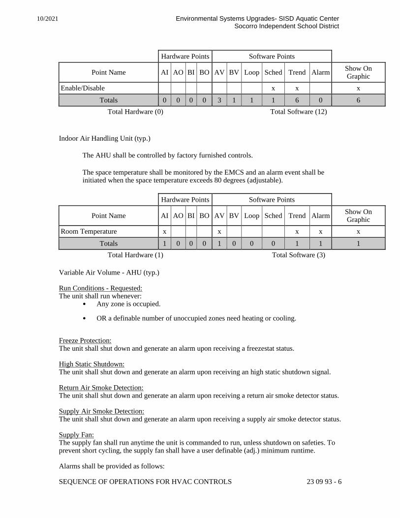
SEQUENCE OF OPERATIONS FOR HVAC CONTROLS 23 09 93 - 6
10/2021 Environmental Systems Upgrades- SISD Aquatic Center Socorro Independent School District
Hardware Points Software Points
Point Name AI AO BI BO AV BV Loop Sched Trend Alarm Show On Graphic
Enable/Disable x x x
Totals 0 0 0 0 3 1 1 1 6 0 6
Total Hardware (0) Total Software (12)
Indoor Air Handling Unit (typ.)
The AHU shall be controlled by factory furnished controls.
The space temperature shall be monitored by the EMCS and an alarm event shall be initiated when the space temperature exceeds 80 degrees (adjustable).
Hardware Points Software Points
Point Name AI AO BI BO AV BV Loop Sched Trend Alarm Show On Graphic
Room Temperature x x x x x
Totals 1 0 0 0 1 0 0 0 1 1 1
Total Hardware (1) Total Software (3)
Variable Air Volume - AHU (typ.) Run Conditions - Requested: The unit shall run whenever:
• Any zone is occupied.
• OR a definable number of unoccupied zones need heating or cooling.
Freeze Protection: The unit shall shut down and generate an alarm upon receiving a freezestat status. High Static Shutdown: The unit shall shut down and generate an alarm upon receiving an high static shutdown signal. Return Air Smoke Detection: The unit shall shut down and generate an alarm upon receiving a return air smoke detector status. Supply Air Smoke Detection: The unit shall shut down and generate an alarm upon receiving a supply air smoke detector status. Supply Fan: The supply fan shall run anytime the unit is commanded to run, unless shutdown on safeties. To prevent short cycling, the supply fan shall have a user definable (adj.) minimum runtime. Alarms shall be provided as follows:

SEQUENCE OF OPERATIONS FOR HVAC CONTROLS 23 09 93 - 7
10/2021 Environmental Systems Upgrades- SISD Aquatic Center Socorro Independent School District
• Supply Fan Failure: Commanded on, but the status is off.
• Supply Fan in Hand: Commanded off, but the status is on.
• Supply Fan Runtime Exceeded: Status runtime exceeds a user definable limit (adj.).
Supply Air Duct Static Pressure Control: The controller shall measure duct static pressure and modulate the supply fan VFD speed to maintain a duct static pressure setpoint. The speed shall not drop below 30% (adj.). The static pressure setpoint shall be reset based upon the position of the zone dampers, with a goal of reducing the static pressure until at least one zone damper is nearly wide open.
• The initial duct static pressure setpoint shall be 1.5in H2O (adj.).
• If no zone damper is nearly wide open, the setpoint shall incrementally reset down to a minimum of 1.3in H2O (adj.) .
• As one or more dampers nears the wide open position, the setpoint shall incrementally reset up to a maximum of 1.8in H2O (adj.).
Alarms shall be provided as follows:
• High Supply Air Static Pressure: If the supply air static pressure is 25% (adj.) greater than setpoint.
• Low Supply Air Static Pressure: If the supply air static pressure is 25% (adj.) less than setpoint.
• Supply Fan VFD Fault.
Return Fan: The return fan shall run whenever the supply fan runs. Alarms shall be provided as follows:
• Return Fan Failure: Commanded on, but the status is off.
• Return Fan in Hand: Commanded off, but the status is on.
• Return Fan Runtime Exceeded: Status runtime exceeds a user definable limit (adj.).
• Return Fan VFD Fault.
Building Static Pressure Control: The controller shall measure building static pressure and modulate the return fan VFD speed to maintain a building static pressure setpoint of 0.05in H2O (adj.). The return fan VFD speed shall not drop below 20% (adj.). Alarms shall be provided as follows:
• High Building Static Pressure: If the building air static pressure is 25% (adj.) greater than setpoint.
• Low Building Static Pressure: If the building air static pressure is 25% (adj.) less than setpoint.

SEQUENCE OF OPERATIONS FOR HVAC CONTROLS 23 09 93 - 8
10/2021 Environmental Systems Upgrades- SISD Aquatic Center Socorro Independent School District
Gas Preheating Stage: The controller shall measure the mixed air temperature and stage the preheating to maintain its setpoint 5°F (adj.) less than the supply air temperature setpoint. To prevent short cycling, the stage shall have a user definable (adj.) minimum runtime. The preheating shall be enabled whenever:
• Outside air temperature is less than 60°F (adj.).
• AND the economizer (if present) is disabled.
• AND the supply fan status is on.
The preheating stage shall run for freeze protection whenever:
• Mixed air temperature drops from 40°F to 35°F (adj.).
• AND the supply fan status is on.
Supply Air Temperature Setpoint - Optimized: The controller shall monitor the supply air temperature and shall maintain a supply air temperature setpoint reset based on zone cooling and heating requirements The supply air temperature setpoint shall be reset for cooling based on zone cooling requirements as follows:
• The initial supply air temperature setpoint shall be 55°F (adj.).
• As cooling demand increases, the setpoint shall incrementally reset down to a minimum of 53°F (adj.).
• As cooling demand decreases, the setpoint shall incrementally reset up to a maximum of 72°F (adj.) .
If more zones need heating than cooling, then the supply air temperature setpoint shall be reset for heating as follows:
• The initial supply air temperature setpoint shall be 82°F (adj.).
• As heating demand increases, the setpoint shall incrementally reset up to a maximum of 85°F (adj.).
• As heating demand decreases, the setpoint shall incrementally reset down to a minimum of 72°F (adj.).
Cooling Coil Valve: The controller shall measure the supply air temperature and modulate the cooling coil valve to maintain its cooling setpoint. The cooling shall be enabled whenever:
• Outside air temperature is greater than 60°F (adj.).
• AND the economizer (if present) is disabled or fully open.

SEQUENCE OF OPERATIONS FOR HVAC CONTROLS 23 09 93 - 9
10/2021 Environmental Systems Upgrades- SISD Aquatic Center Socorro Independent School District
• AND the supply fan status is on.
• AND the heating (if present) is not active.
The cooling coil valve shall open to 50% (adj.) whenever the freezestat (if present) is on. Alarms shall be provided as follows:
• High Supply Air Temp: If the supply air temperature is 5°F (adj.) greater than setpoint.
Heating Coil Valve: The controller shall measure the supply air temperature and modulate the heating coil valve to maintain its heating setpoint. The heating shall be enabled whenever:
• Outside air temperature is less than 65°F (adj.).
• AND the supply fan status is on.
• AND the cooling (if present) is not active.
The heating coil valve shall open whenever:
• Supply air temperature drops from 40°F to 35°F (adj.).
• OR the freezestat (if present) is on.
Alarms shall be provided as follows:
• Low Supply Air Temp: If the supply air temperature is 5°F (adj.) less than setpoint.
Economizer: The controller shall measure the mixed air temperature and modulate the economizer dampers in sequence to maintain a setpoint 2°F (adj.) less than the supply air temperature setpoint. The outside air dampers shall maintain a minimum adjustable position of 20% (adj.) open whenever occupied. The economizer shall be enabled whenever:
• Outside air temperature is less than 65°F (adj.).
• AND the outside air enthalpy is less than 22Btu/lb (adj.)
• AND the outside air temperature is less than the return air temperature.
• AND the outside air enthalpy is less than the return air enthalpy.
• AND the supply fan status is on.
The economizer shall close whenever:
• Mixed air temperature drops from 40°F to 35°F (adj.)
• OR the freezestat (if present) is on.
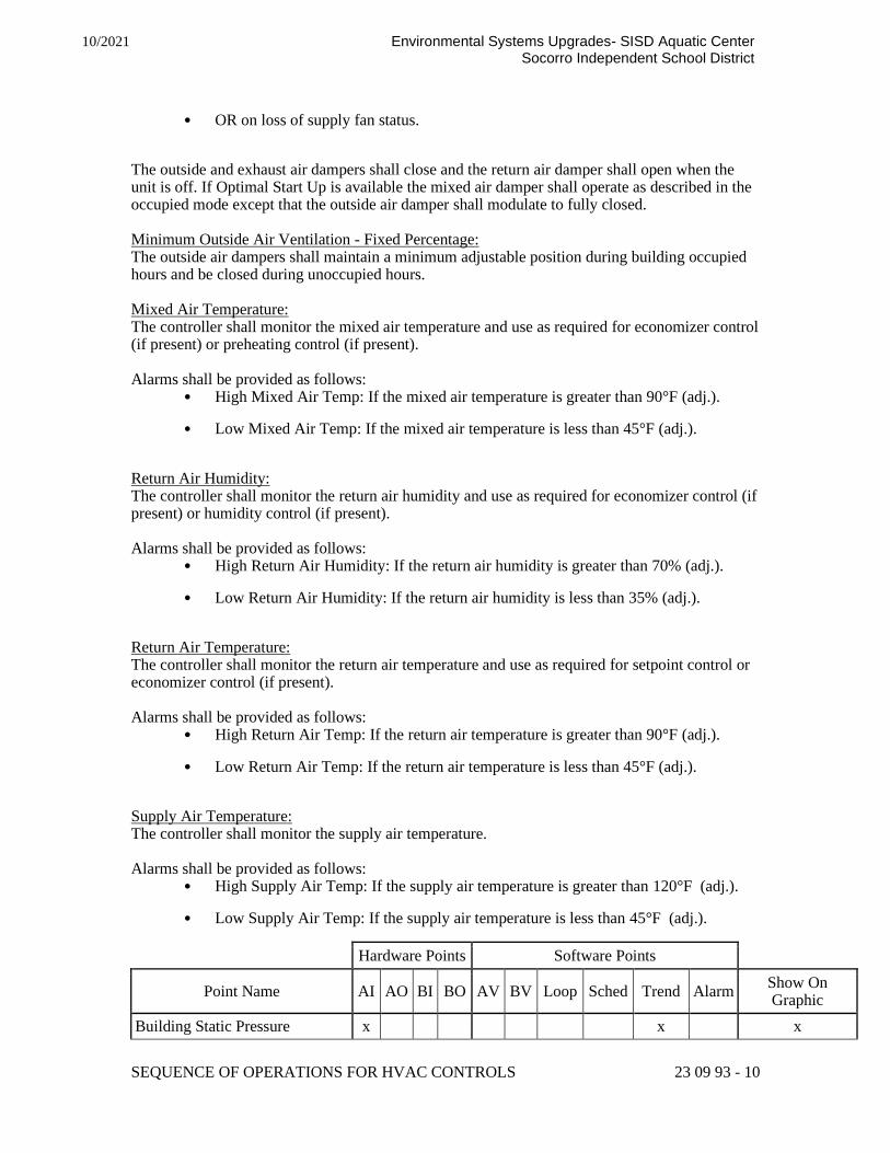
SEQUENCE OF OPERATIONS FOR HVAC CONTROLS 23 09 93 - 10
10/2021 Environmental Systems Upgrades- SISD Aquatic Center Socorro Independent School District
• OR on loss of supply fan status.
The outside and exhaust air dampers shall close and the return air damper shall open when the unit is off. If Optimal Start Up is available the mixed air damper shall operate as described in the occupied mode except that the outside air damper shall modulate to fully closed. Minimum Outside Air Ventilation - Fixed Percentage: The outside air dampers shall maintain a minimum adjustable position during building occupied hours and be closed during unoccupied hours. Mixed Air Temperature: The controller shall monitor the mixed air temperature and use as required for economizer control (if present) or preheating control (if present). Alarms shall be provided as follows:
• High Mixed Air Temp: If the mixed air temperature is greater than 90°F (adj.).
• Low Mixed Air Temp: If the mixed air temperature is less than 45°F (adj.).
Return Air Humidity: The controller shall monitor the return air humidity and use as required for economizer control (if present) or humidity control (if present). Alarms shall be provided as follows:
• High Return Air Humidity: If the return air humidity is greater than 70% (adj.).
• Low Return Air Humidity: If the return air humidity is less than 35% (adj.).
Return Air Temperature: The controller shall monitor the return air temperature and use as required for setpoint control or economizer control (if present). Alarms shall be provided as follows:
• High Return Air Temp: If the return air temperature is greater than 90°F (adj.).
• Low Return Air Temp: If the return air temperature is less than 45°F (adj.).
Supply Air Temperature: The controller shall monitor the supply air temperature. Alarms shall be provided as follows:
• High Supply Air Temp: If the supply air temperature is greater than 120°F (adj.).
• Low Supply Air Temp: If the supply air temperature is less than 45°F (adj.).
Hardware Points Software Points
Point Name AI AO BI BO AV BV Loop Sched Trend Alarm Show On Graphic
Building Static Pressure x x x

SEQUENCE OF OPERATIONS FOR HVAC CONTROLS 23 09 93 - 11
10/2021 Environmental Systems Upgrades- SISD Aquatic Center Socorro Independent School District
Hardware Points Software Points
Point Name AI AO BI BO AV BV Loop Sched Trend Alarm Show On Graphic
Mixed Air Temp x x x
Return Air Humidity x x x
Return Air Temp x x x
Supply Air Static Pressure x x x x
Supply Air Temp x x x
Cooling Valve x x x
Heating Valve x x x
Mixed Air Dampers x x x
Return Fan VFD Speed x x x
Supply Fan VFD Speed x x x
Freezestat x x x x
High Static Shutdown x x x x
Return Air Smoke Detector x x x x
Return Fan Status x x x
Return Fan VFD Fault x x
Supply Air Smoke Detector x x x x
Supply Fan Status x x x
Supply Fan VFD Fault x x x
Preheating Stage 1 x x x
Return Fan Start/Stop x x x
Supply Fan Start/Stop x x x
Building Static Pressure Setpoint x x x
Economizer Mixed Air Temp Setpoint
x x x
Preheating Mixed Air Temp Setpoint
x x x
Supply Air Static Pressure Setpoint
x x x
Supply Air Temp Setpoint x x x
High Building Static Pressure x
High Mixed Air Temp x
High Return Air Humidity x
High Return Air Temp x
High Supply Air Static Pressure x
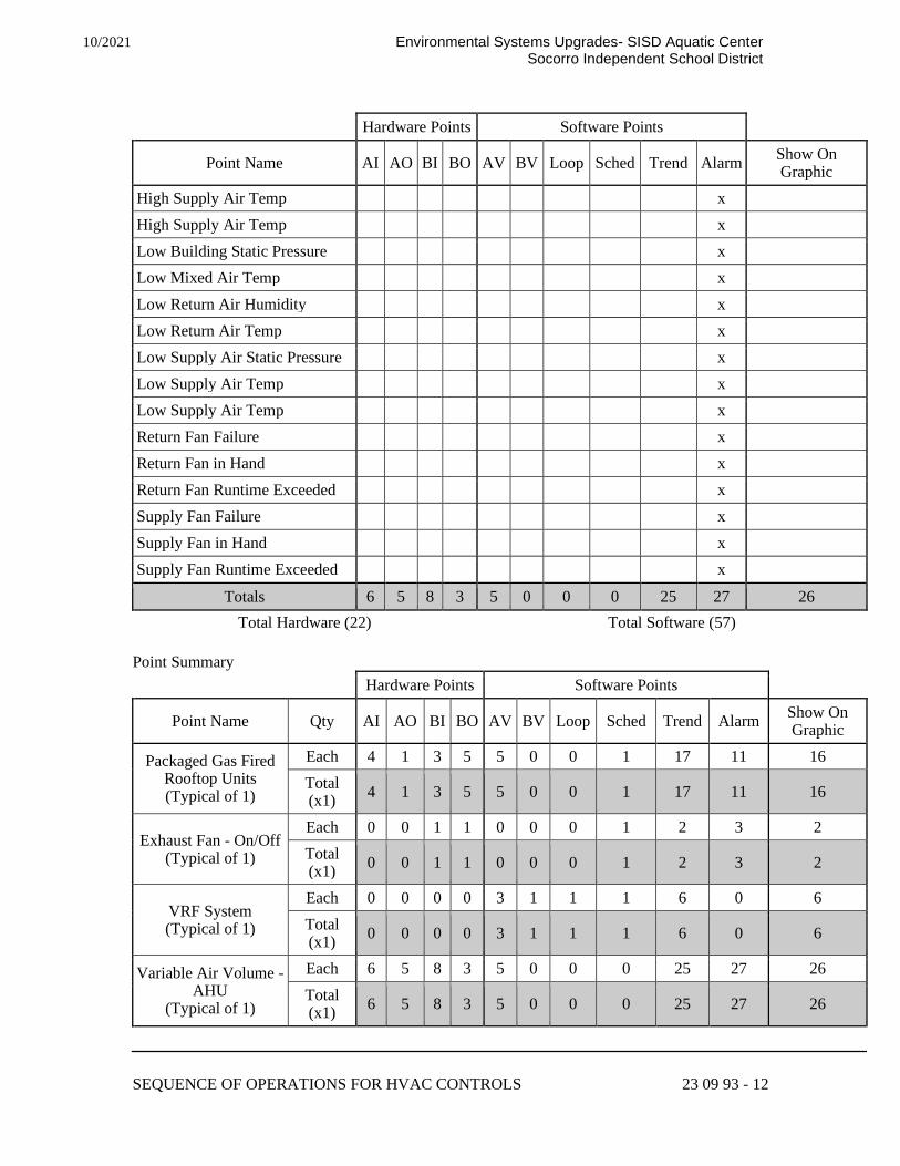
SEQUENCE OF OPERATIONS FOR HVAC CONTROLS 23 09 93 - 12
10/2021 Environmental Systems Upgrades- SISD Aquatic Center Socorro Independent School District
Hardware Points Software Points
Point Name AI AO BI BO AV BV Loop Sched Trend Alarm Show On Graphic
High Supply Air Temp x
High Supply Air Temp x
Low Building Static Pressure x
Low Mixed Air Temp x
Low Return Air Humidity x
Low Return Air Temp x
Low Supply Air Static Pressure x
Low Supply Air Temp x
Low Supply Air Temp x
Return Fan Failure x
Return Fan in Hand x
Return Fan Runtime Exceeded x
Supply Fan Failure x
Supply Fan in Hand x
Supply Fan Runtime Exceeded x
Totals 6 5 8 3 5 0 0 0 25 27 26
Total Hardware (22) Total Software (57)
Point Summary
Hardware Points Software Points
Point Name Qty AI AO BI BO AV BV Loop Sched Trend Alarm Show On Graphic
Packaged Gas Fired Rooftop Units (Typical of 1)
Each 4 1 3 5 5 0 0 1 17 11 16
Total (x1)
4 1 3 5 5 0 0 1 17 11 16
Exhaust Fan - On/Off (Typical of 1)
Each 0 0 1 1 0 0 0 1 2 3 2
Total (x1)
0 0 1 1 0 0 0 1 2 3 2
VRF System (Typical of 1)
Each 0 0 0 0 3 1 1 1 6 0 6
Total (x1)
0 0 0 0 3 1 1 1 6 0 6
Variable Air Volume - AHU
(Typical of 1)
Each 6 5 8 3 5 0 0 0 25 27 26
Total (x1)
6 5 8 3 5 0 0 0 25 27 26

SEQUENCE OF OPERATIONS FOR HVAC CONTROLS 23 09 93 - 13
10/2021 Environmental Systems Upgrades- SISD Aquatic Center Socorro Independent School District
Hardware Points Software Points
Project Totals 10 6 12 9 13 1 1 3 50 41 50
Total Hardware (37) Total Software (109)
Outside Air Conditions (typ.)
Outside Air Conditions:
The controller shall monitor the outside air temperature and humidity and calculate the
outside air enthalpy on a continual basis. These values shall be made available to the
system at all times.
Alarm shall be generated as follows:
• Sensor Failure: Sensor reading indicates shorted or disconnected sensor. In the event of a sensor failure, an alternate outside air conditions sensor shall be made available to the system without interruption in sensor readings.
If an OA Temp Sensor cannot be read, a default value of 65°F will be used.
If an OA Humidity Sensor cannot be read, a default value of 50 % will be used.
Outside Air Temperature History:
The controller shall monitor and record the high and low temperature readings for the
outside air. These readings shall be recorded on a daily, month-to-date, and year-to-date
basis.
Hardware Points Software Points
Point Name AI AO BI BO AV BV Loop Sched Trend Alarm Show On
Graphic
Outside Air Humidity x x x
Outside Air Temp x x x
Outside Air Enthalpy x x x
High Temp Month-to-Date x x
High Temp Today x x
High Temp Year-to-Date x x
Low Temp Month-to-Date x x
Low Temp Today x x
Low Temp Year-to-Date x x
Sensor Failure x
Totals 2 0 0 0 1 0 0 0 9 1 9

SEQUENCE OF OPERATIONS FOR HVAC CONTROLS 23 09 93 - 14
10/2021 Environmental Systems Upgrades- SISD Aquatic Center Socorro Independent School District
Hardware Points Software Points
Point Name AI AO BI BO AV BV Loop Sched Trend Alarm Show On
Graphic
Total Hardware (2) Total Software (11)
Hot Water Loop Pumps (typ.) Hot Water Pump Run Conditions: The hot water pumps shall be enabled whenever:
• A definable number of hot water coils need heating.
• AND outside air temperature is less than 65°F (adj.).
The pumps shall run for freeze protection anytime outside air temperature is less than 38°F (adj.).
To prevent short cycling, the pump shall run for a minimum time and be off for a minimum time (both user adjustable). Hot Water Pump Lead/Lag Operation: The two hot water pumps shall operate in a lead/lag fashion.
• The lead pump shall run first.
• On failure of the lead pump, the lag pump shall run and the lead pump shall turn off.
• On decreasing hot water differential pressure, the lag pump shall stage on and run in unison with the lead pump to maintain hot water differential pressure setpoint.
The designated lead pump shall rotate upon one of the following conditions (user selectable):
• manually through a software switch
• if pump runtime (adj.) is exceeded
• daily
• weekly
• monthly
Alarms shall be provided as follows: • Hot Water Pump 1
• Failure: Commanded on, but the status is off.
• Running in Hand: Commanded off, but the status is on.
• Runtime Exceeded: Status runtime exceeds a user definable limit.
• Hot Water Pump 2

SEQUENCE OF OPERATIONS FOR HVAC CONTROLS 23 09 93 - 15
10/2021 Environmental Systems Upgrades- SISD Aquatic Center Socorro Independent School District
• Failure: Commanded on, but the status is off.
• Running in Hand: Commanded off, but the status is on.
• Runtime Exceeded: Status runtime exceeds a user definable limit.
Hot Water Differential Pressure Control: The controller shall measure hot water differential pressure and stage the hot water pumps on in sequence to maintain its hot water differential pressure setpoint. The lead pump shall run first. The following setpoints are recommended values. All setpoints shall be field adjusted during the commissioning period to meet the requirements of actual field conditions. If the hot water differential pressure drops below a setpoint of 12lbf/in2 (adj.), the lag pump shall turn on and run in unison with the lead pump. If the hot water differential pressure rises back to 4lbf/in2 (adj.) above setpoint, the lag pump shall turn off and the lead pump shall continue to run. To prevent short cycling, there shall be a minimum user definable (adj.) delay between stages. Alarms shall be provided as follows:
• High Hot Water Differential Pressure: If the hot water differential pressure is greater than 18lbf/in2 (adj.).
• Low Hot Water Differential Pressure: If the hot water differential pressure is less than 10lbf/in2 (adj.).
The following temperatures shall be monitored: • Hot water supply.
• Hot water return.
Alarms shall be provided as follows: • High Hot Water Supply Temp: If the hot water supply temperature is greater
than 200°F (adj.).
• Low Hot Water Supply Temp: If the hot water supply temperature is less than 100°F (adj.).
Hardware Points Software Points
Point Name AI AO BI BO AV BV Loop Sched Trend Alarm Show On Graphic
Hot Water Differential Pressure
x x x
Hot Water Return Temp x x x
Hot Water Supply Temp x x x
Hot Water Pump 1 Status x x x

SEQUENCE OF OPERATIONS FOR HVAC CONTROLS 23 09 93 - 16
10/2021 Environmental Systems Upgrades- SISD Aquatic Center Socorro Independent School District
Hardware Points Software Points
Point Name AI AO BI BO AV BV Loop Sched Trend Alarm Show On Graphic
Hot Water Pump 2 Status x x x
Hot Water Pump 1 Start/Stop x x x
Hot Water Pump 2 Start/Stop x x x
Hot Water Differential Pressure Setpoint
x x
Outside Air Temp x x
High Hot Water Differential Pressure
x
High Hot Water Supply Temp x
Hot Water Pump 1 Failure x
Hot Water Pump 1 Running in Hand
x
Hot Water Pump 1 Runtime Exceeded
x
Hot Water Pump 2 Failure x
Hot Water Pump 2 Running in Hand
x
Hot Water Pump 2 Runtime Exceeded
x
Low Hot Water Differential Pressure
x
Low Hot Water Supply Temp x
Totals 3 0 2 2 2 0 0 0 7 10 9
Total Hardware (7) Total Software (19)
Single Boiler System (typ.) Cold Water Start: A three-way valve shall be provided at the boiler and shall be controlled by the EMCS. Three-way valve shall be modulated to maintain a return water temperature greater than 120°F during start-up conditions. Once the system is heated up and has return water temperatures of 120°F or higher, the mixing of outlet water with inlet water is no longer needed and the bypass shall be shut off. Boiler System Run Conditions: The boiler system shall be enabled to run whenever:
• A definable number of hot water coils need heating.
• AND outside air temperature is less than 65°F (adj.).

SEQUENCE OF OPERATIONS FOR HVAC CONTROLS 23 09 93 - 17
10/2021 Environmental Systems Upgrades- SISD Aquatic Center Socorro Independent School District
To prevent short cycling, the boiler system shall run for and be off for minimum adjustable times (both user definable), unless shutdown on safeties or outside air conditions. The boiler shall run subject to its own internal safeties and controls. The boiler system shall also run for freeze protection whenever outside air temperature is less than 38°F (adj.). Boiler Safeties: The following safeties shall be monitored:
• Boiler alarm.
• Low Water Level.
Alarms shall be provided as follows:
• Boiler alarm.
• Low Water Level alarm.
Hot Water Pump Lead/Lag Operation: The two hot water pumps shall operate in a lead/lag fashion.
• The lead pump shall run first.
• On failure of the lead pump, the lag pump shall run and the lead pump shall turn off.
• On decreasing hot water differential pressure, the lag pump shall stage on and run in unison with the lead pump to maintain hot water differential pressure setpoint.
The designated lead pump shall rotate upon one of the following conditions (user selectable):
• manually through a software switch
• if pump runtime (adj.) is exceeded
• daily
• weekly
• monthly
Alarms shall be provided as follows:
• Hot Water Pump 1
• Failure: Commanded on, but the status is off.
• Running in Hand: Commanded off, but the status is on.
• Runtime Exceeded: Status runtime exceeds a user definable limit.

SEQUENCE OF OPERATIONS FOR HVAC CONTROLS 23 09 93 - 18
10/2021 Environmental Systems Upgrades- SISD Aquatic Center Socorro Independent School District
• Hot Water Pump 2
• Failure: Commanded on, but the status is off.
• Running in Hand: Commanded off, but the status is on.
• Runtime Exceeded: Status runtime exceeds a user definable limit.
Hot Water Differential Pressure Control: The controller shall measure hot water differential pressure and stage the hot water pumps on in sequence to maintain its hot water differential pressure setpoint. The lead pump shall run first. The following setpoints are recommended values. All setpoints shall be field adjusted during the commissioning period to meet the requirements of actual field conditions. If the hot water differential pressure drops below a setpoint of 12lbf/in2 (adj.), the lag pump shall turn on and run in unison with the lead pump. If the hot water differential pressure rises back to 4lbf/in2 (adj.) above setpoint, the lag pump shall turn off and the lead pump shall continue to run. To prevent short cycling, there shall be a minimum user definable (adj.) delay between stages. Alarms shall be provided as follows:
• High Hot Water Differential Pressure: If the hot water differential pressure is greater than 18lbf/in2 (adj.).
• Low Hot Water Differential Pressure: If the hot water differential pressure is less than 10lbf/in2 (adj.).
Circulation Pump: The circulation pump shall run anytime the boiler is called to run and shall have a user definable (adj.) delay on stop. Alarms shall be provided as follows:
• Circulation Pump Failure: Commanded on, but the status is off.
• Circulation Pump Running in Hand: Commanded off, but the status is on.
• Circulation Pump Runtime Exceeded: Status runtime exceeds a user definable limit.
Boiler Enable: The boiler shall be enabled when the boiler system is commanded on. The boiler shall be enabled after pump status is proven on and shall run subject to its own internal safeties and controls. Alarms shall be provided as follows:
• Boiler Failure: Commanded on, but the status is off.

SEQUENCE OF OPERATIONS FOR HVAC CONTROLS 23 09 93 - 19
10/2021 Environmental Systems Upgrades- SISD Aquatic Center Socorro Independent School District
• Boiler Running in Hand: Commanded off, but the status is on.
• Boiler Runtime Exceeded: Status runtime exceeds a user definable limit.
Hot Water Supply Temperature Setpoint: The boiler shall maintain a hot water supply temperature setpoint as determined by its own internal controls (provided by others). Primary Hot Water Temperature Monitoring: The following temperatures shall be monitored:
• Primary hot water supply.
• Primary hot water return.
Alarms shall be provided as follows: • High Primary Hot Water Supply Temp: If greater than 200°F (adj.).
• Low Primary Hot Water Supply Temp: If less than 100°F (adj.).
Hardware Points Software Points
Point Name AI AO BI BO AV BV Loop Sched Trend Alarm Show On Graphic
Hot Water Differential Pressure
x x x
Primary Hot Water Return Temp
x x x
Primary Hot Water Supply Temp
x x x
Boiler Alarm Status x x x x
Boiler Status x x x
Circulation Pump Status x x x
Hot Water Pump 1 Status x x x
Hot Water Pump 2 Status x x x
Low Water Level x x x x
Boiler Enable x x
Circulation Pump Start/Stop x x x
Hot Water Pump 1 Start/Stop x x
Hot Water Pump 2 Start/Stop x x
Hot Water Differential Pressure Setpoint
x x
Outside Air Temp x x
Boiler Failure x
Boiler Running in Hand x

SEQUENCE OF OPERATIONS FOR HVAC CONTROLS 23 09 93 - 20
10/2021 Environmental Systems Upgrades- SISD Aquatic Center Socorro Independent School District
Hardware Points Software Points
Point Name AI AO BI BO AV BV Loop Sched Trend Alarm Show On Graphic
Boiler Runtime Exceeded x
Circulation Pump Failure x
Circulation Pump Running in Hand
x
Circulation Pump Runtime Exceeded
x
High Hot Water Differential Pressure
x
High Primary Hot Water Supply Temp
x
Hot Water Pump 1 Failure x
Hot Water Pump 1 Running in Hand
x
Hot Water Pump 1 Runtime Exceeded
x
Hot Water Pump 2 Failure x
Hot Water Pump 2 Running in Hand
x
Hot Water Pump 2 Runtime Exceeded
x
Low Hot Water Differential Pressure
x
Low Primary Hot Water Supply Temp
x
Totals 3 0 6 4 2 0 0 0 10 18 15
Total Hardware (13) Total Software (30)

SEQUENCE OF OPERATIONS FOR HVAC CONTROLS 23 09 93 - 21
10/2021 Environmental Systems Upgrades- SISD Aquatic Center Socorro Independent School District
Point Summary
Hardware Points Software Points
Point Name Qty AI AO BI BO AV BV Loop Sched Trend Alarm Show On Graphic
Hot Water Loop Pumps
(Typical of 1)
Each 3 0 2 2 2 0 0 0 7 10 9
Total (x1)
3 0 2 2 2 0 0 0 7 10 9
Single Boiler System
(Typical of 1)
Each 3 0 6 4 2 0 0 0 10 18 15
Total (x1)
3 0 6 4 2 0 0 0 10 18 15
Project Totals 6 0 8 6 4 0 0 0 17 28 24
Total Hardware (20) Total Software (49)
APPENDIX A: Glossary of Terms
Terms used within the Specification Text:
• Advanced Application Controller (AAC): A fully programmable control module. This control module may be capable of some of the advanced features found in Building Controllers (storing trends, initiating read and write requests, etc.) but it does not serve as a master controller. Advanced Application Controllers may reside on either the Ethernet/IP backbone or on a subnet.
• Application Specific Controller (ASC): A pre-programmed control module which is intended for use in a specific application. ASCs may be configurable, in that the user can choose between various pre-programmed options, but it does not support full custom programming. ASCs are often used on terminal equipment such as VAV boxes or fan coil units. In many vendors' architectures ASCs do not store trends or schedules but instead rely upon a Building Controller to provide those functions.
• BACnet/IP: An approved BACnet network type which uses an Ethernet carrier and IP addressing.
• BACnet MS/TP: An approved BACnet network type which uses a Master-Slave Token Passing configuration. MS/TP networks are unique to BACnet and utilize EIA485 twisted pair topology running at 9600 to 76,800 bps.
• BACnet over ARCNET:

SEQUENCE OF OPERATIONS FOR HVAC CONTROLS 23 09 93 - 22
10/2021 Environmental Systems Upgrades- SISD Aquatic Center Socorro Independent School District
An approved BACnet network type which uses an ARCNET (attached resource computer network) carrier. ARCNET is an industry standard that can utilize several speeds and wiring standards. The most common configuration used by BACnet controllers is an EIA485 twisted pair topology running at 156,000 bps.
• Building Controller (BC): A fully programmable control module which is capable of storing trends and schedules, serving as a router to devices on a subnet, and initiating read and write requests to other controllers. Typically this controller is located on the Ethernet/IP backbone of the BAS. In many vendors' architectures a Building Controller will serve as a master controller, storing schedules and trends for controllers on a subnet underneath the Building Controller.
• Direct Digital Control (DDC): A control system in which a digital computer or microprocessor is directly connected to the valves, dampers, and other actuators which control the system, as opposed to indirectly controlling a system by resetting setpoints on an analog pneumatic or electronic controller.
• PICS - Protocol Implementation Conformance Statement: A written document, created by the manufacturer of a device, which identifies the particular options specified by BACnet that are implemented in the device.
• Smart Actuator (SA): An actuator which is controlled by a network connection rather than a binary or analog signal. (0-10v, 4-20mA, relay, etc.)
• Smart Sensor (SS): A sensor which provides information to the BAS via network connection rather than a binary or analog signal. (0-10000 ohm, 4-20mA, dry contact, etc.)
• Web services: Web services are a standard method of exchanging data between computer systems using the XML (extensible markup language) and SOAP (simple object access protocol) standards. Web services can be used at any level within a Building Automation System (BAS), but most commonly they are used to transfer data between BAS using different protocols or between a BAS and a non-BAS system such as a tenant billing system or a utility management system.
Terms used within the Sequences of Operation:
• adj. Adjustable by the end user, through the supplied user interface.
• AI, AO, etc. (Column Headings on Points List) AI = Analog Input. A physical input to the control module.

SEQUENCE OF OPERATIONS FOR HVAC CONTROLS 23 09 93 - 23
10/2021 Environmental Systems Upgrades- SISD Aquatic Center Socorro Independent School District
AO = Analog Output. A physical output from the control module. AV = Analog Value. An intermediate (software) point that may be editable or read-only. Editable AVs are typically used to allow the user to set a fixed control parameter, such as a setpoint. Read Only AVs are typically used to display the status of a control operation. BI = Binary Input. A physical input to the control module. BO = Binary Output. A physical output from the control module. BV = Binary Value. An intermediate (software) point that may be editable or read-only. Editable BVs are typically used to allow the user to set a fixed control parameter, such as a setpoint. Read Only BVs are typically used to display the status of a control operation. Loop = A control loop. Most commonly a PID control loop. Typically a control loop will include a setpoint, an input which is compared to the setpoint, and an output which controls some action based upon the difference between the input and the setpoint. A PID control loop will also include gains for the proportional, integral, and derivative response as well as an interval which controls how frequently the control loop updates its output. These gains may be adjustable by the end user for control loop "tuning," but in self-tuning control loops or loops which have been optimized for a specific application the gains may not be adjustable. Sched = Schedule. The control algorithm for this equipment shall include a user editable schedule. Trend. The control system shall be configured to collect and display a trend log of this object. The trending interval shall be no less than one sample every 5 minutes. (Change of Value trending, where a sample is taken every time the value changes by more than a user-defined minimum, is an acceptable alternative.) Alarm. The control system shall be configured to generate an alarm when this object exceeds user definable limits, as described in the Sequence of Controls. Note: If the specifications require use of the BACnet protocol, all of the above shall be provided as BACnet objects.
• KW Demand Limiting: * An energy management strategy that reduces energy consumption when a system's electric power meter exceeds an operator-defined threshold. When power consumption exceeds defined levels, the system automatically adjust setpoints, de-energizes low priority equipment, and takes other pre-programmed actions to avoid peak demand charges. As the demand drops, the system restores loads in a predetermined manner.
• Occupant Override Switch, or Timed Local Override: A control option that allows building occupants to override the programmed HVAC schedule for a limited period of time. When the override time expires, the zone returns to its unoccupied state.
• Occupant Setpoint Adjustment: A control option that allows building occupants to adjust - within limits set by the HVAC control system - the heating and cooling setpoints of selected zones. Typically the user interface for this function is built into the zone sensor.

SEQUENCE OF OPERATIONS FOR HVAC CONTROLS 23 09 93 - 24
10/2021 Environmental Systems Upgrades- SISD Aquatic Center Socorro Independent School District
• Optimal Start-Up: * A control strategy that automatically starts an HVAC system at the latest possible time yet ensures comfort conditions by the time the building becomes occupied. In a typical implementation, a controller measures the temperature of the zone and the outside air. Then, using design heating or cooling capacity at the design outside air temperature, the system computes how long a unit must run at maximum capacity to bring the zone temperature to its occupied setpoint. The optimal start algorithm often includes a self-learning feature to adjust for variations from design capacity. A distributed system must use Run on Request with Optimal Start. (See below.)
• Requested, or Run on Request: * A control strategy that optimizes the runtime of a source piece of equipment that supplies one or more receiving units - such as an air handler unit supplying zone terminal units with heating, cooling, ventilation, or similar service. Source equipment runs only when needed, not on a fixed schedule. The source equipment runs when one or more receiving units request its services. An operator determines how many requests are required to start the source equipment. For example, if all the zones in a building are unoccupied and the zone terminal units do not need heating or cooling, the AHU will shut down. However, if a zone becomes occupied or needs cooling, the terminal unit will send a run request to the AHU to initiate the start-up sequence. If this AHU depends on a central chiller, it can send a run request to the chiller. The run on request algorithm also allows an operator to schedule occupancy for individual zones based on the needs of the occupants without having to adjust the schedules of related AHUs and chillers.
• Trim and Respond, or Setpoint Optimization: * A control strategy that optimizes the setpoint of a source piece of equipment that supplies one or more receiving units - such as an air handler unit supplying zone terminal units with heating, cooling, ventilation, or similar service. The source unit communicates with receiving units to determine heating, cooling, and other requirements, and then adjusts its setpoint. For example, if all zones are comfortable and do not request cooling, the AHU will gradually increase (trim) its supply air setpoint. When a zone requests cooling, the AHU responds by dropping its setpoint. The more zones that request cooling, the more it drops the setpoint. The AHU repeats this process throughout the day to keep zones cool, but with a supply air setpoint that is no cooler than necessary.
Contracting Terms:

SEQUENCE OF OPERATIONS FOR HVAC CONTROLS 23 09 93 - 25
10/2021 Environmental Systems Upgrades- SISD Aquatic Center Socorro Independent School District
• Furnished or Provided: The act of supplying a device or piece of equipment as required meeting the scope of work specified and making that device or equipment operational. All costs required to furnish the specified device or equipment and make it operational are borne by the division specified to be responsible for providing the device or equipment.
• Install or Installed: The physical act of mounting, piping or wiring a device or piece of equipment in accordance with the manufacturer's instructions and the scope of work as specified. All costs required to complete the installation are borne by the division specified to include labor and any ancillary materials.
• Interface: The physical device required to provide integration capabilities from an equipment vendor's product to the control system. The equipment vendor most normally furnishes the interface device. An example of an interface is the chilled water temperature reset interface card provided by the chiller manufacturer in order to allow the control system to integrate the chilled water temperature reset function into the control system.
• Integrate: The physical connections from a control system to all specified equipment through an interface as required to allow the specified control and monitoring functions of the equipment to be performed via the control system.
APPENDIX B: Abbreviations
The following abbreviations may be used in graphics, schematics, point names, and other UI applications where space is at a premium.
AC - Air Conditioning ACU - Air Conditioning Unit AHU - Air Handling Unit AI - Analog Input AO - Analog Output AUTO - Automatic AUX - Auxiliary BI - Binary Input BO - Binary Output C - Common CHW - Chilled Water CHWP - Chilled Water Pump CHWR - Chilled Water Return CHWS - Chilled Water Supply COND - Condenser CW - Condenser Water CWP - Condenser Water Pump CWR - Condenser Water Return CWS - Condenser Water Supply DA - Discharge Air

SEQUENCE OF OPERATIONS FOR HVAC CONTROLS 23 09 93 - 26
10/2021 Environmental Systems Upgrades- SISD Aquatic Center Socorro Independent School District
EA - Exhaust Air EF - Exhaust Fan EVAP - Evaporators FCU - Fan Coil Unit HOA - Hand / Off / Auto HP - Heat Pump HRU - Heat Recovery Unit HTEX - Heat Exchanger HW - Hot Water HWP - Hot Water Pump HWR - Hot Water Return HWS - Hot Water Supply MAX - Maximum MIN - Minimum MISC - Miscellaneous NC - Normally Closed NO - Normally Open OA - Outdoor Air PIU - Powered Induction Unit RA - Return Air RF - Return Fan RH - Relative Humidity RTU - Roof-top Unit SA - Supply Air SF - Supply Fan SP - Static Pressure TEMP - Temperature UH - Unit Heater UV - Unit Ventilator VAV - Variable Air Volume VVTU - Variable Volume Terminal Unit W/ - with W/O - without WSHP - Water Source Heat Pump

REFRIGERANT PIPING 232300 - 1
10/2021 Environmental Systems Upgrades- SISD Aquatic Center Socorro Independent School District
SECTION 232300 - REFRIGERANT PIPING
PART 1 - GENERAL
1.1 SCOPE OF WORK
A. The Scope of the Work of this Section of the Specifications shall include the furnishing
of all labor, materials, tools, equipment and services required to complete the Refrigerant
Handling, Pipe, Valves, Fittings & Specialties Work as hereinafter specified or as
indicated on the drawings or as noted in the equipment manufacturers piping
specifications and drawings. Without limiting the above "Scope" the work shall generally
include, but is not necessarily limited to the following:
1. Providing of pipe, pipe fittings, valves, specialties, controls and accessories
specifically manufactured for refrigeration service in accordance with the
requirements hereinafter specified and the equipment manufacturer installation
manual.
2. Proper refrigerant handling, installation and removal as required.
3. All work shall comply with equipment manufacturers written installation
instructions.
B. Related work specified in other Divisions or Sections of the Specifications shall
generally consist of, but is not necessarily limited to the following:
1. Section 230593 - Testing, Adjusting, And Balancing For HVAC
1.2 PIPE & PIPE FITTINGS
A. Each length of pipe or fitting furnished shall be marked with the manufacturer's name,
brand and specification code designator to which it conforms. All aboveground pipe and
fittings to be painted shall be bare or coated with an easily removed mill primer, while
pipe and fittings to be insulated shall be provided with a regular mill representative
primer with insulation applied over the primer.
1.3 WELDING & BRAZING
A. When welding is required, submit (3) copies of Welding Procedure Specification (WPS)
and three (3) copies of the Brazing Procedure Specification (BPS) when brazing, for all
metals to be used in accordance with ANSI/ASME B31.9 & B31.5 refrigerant piping.
Submit Welder's Performance Qualification, Technique Sheet (QW-487) and Welder/
Operator Qualification Test From (QW-484) as outlined in ASME Code Section IX.
Similar submittals for brazers shall be submitted. All welding procedures shall comply
with AWS D10.9 Qualification of Welding Procedures and Welders for Piping & Tubing.
All brazing procedures shall comply with ANSI AWS B.2.2 “Standard for Brazing
Procedure and Performance Qualifications”. Safety in brazing, welding and cutting of
pipe shall conform to ANSI Z49.1.
1.4 REFRIGERANT HANDLING
A. Refrigerants used on this project specified herein and throughout this specification shall
conform to ANSI/ASHRAE 34, Number Designation and Safety Classification of
Refrigerants.

REFRIGERANT PIPING 232300 - 2
10/2021 Environmental Systems Upgrades- SISD Aquatic Center Socorro Independent School District
B. All refrigeration work on this project shall conform to ANSI/ASHRAE 15, Safety Code
for Mechanical Refrigeration.
C. Addition or removal of refrigerant from equipment, if required, shall be done without
releasing refrigerants to the atmosphere in accordance with the Clean Air Act and
ANSI/ASHRAE 15. Persons handling refrigerants shall be EPA/RSES certified and shall
submit three (3) copies of certification/certificate to be kept on file at the
Architect/Engineer=s office.
1.5 RELATED DOCUMENTS
A. Drawings and general provisions of the Contract, including General and Supplementary
Conditions and Division 01 Specification Sections, apply to this Section.
1.6 SUMMARY
A. This Section includes refrigerant piping used for air-conditioning applications.
1.7 PERFORMANCE REQUIREMENTS
A. Line Test Pressure for Refrigerant R-410A:
1. Suction Lines for Air-Conditioning Applications: 300 psig.
2. Suction Lines for Heat-Pump Applications: 535 psig.
3. Hot-Gas and Liquid Lines: 535 psig.
1.8 ACTION SUBMITTALS
A. Manufacturer's Literature and Product Data: For each type of valve and refrigerant piping
specialty indicated. Include pressure drop, based on manufacturer's test data, for the
following:
1. Thermostatic expansion valves.
2. Solenoid valves.
3. Hot-gas bypass valves.
4. Filter dryers.
5. Strainers.
6. Pressure-regulating valves.
7. Tubing and fittings.
B. Shop Drawings: Show layout of refrigerant piping and specialties, including pipe, tube,
and fitting sizes, flow capacities, valve arrangements and locations, slopes of
horizontal runs, oil traps, double risers, wall and floor penetrations, and equipment
connection details. Show interface and spatial relationships between piping and
equipment.
1. Shop Drawing Scale: 1/4 inch equals 1 foot.
2. Refrigerant piping indicated on Drawings is schematic only. Size piping and
design actual piping layout, including oil traps, double risers, specialties, and
pipe and tube sizes to accommodate, as a minimum, equipment provided,
elevation difference between compressor and evaporator, and length of piping to
ensure proper operation and compliance with warranties of connected equipment.

REFRIGERANT PIPING 232300 - 3
10/2021 Environmental Systems Upgrades- SISD Aquatic Center Socorro Independent School District
1.9 INFORMATIONAL SUBMITTALS
A. Welding certificates.
B. Field quality-control test reports.
1.10 CLOSEOUT SUBMITTALS
A. Operation and Maintenance Data: For refrigerant valves and piping specialties to include
in maintenance manuals.
1.11 QUALITY ASSURANCE
A. Welding: Qualify procedures and personnel according to ASME Boiler and Pressure
Vessel Code: Section IX, "Welding and Brazing Qualifications."
B. Comply with ASHRAE 15, "Safety Code for Refrigeration Systems."
C. Comply with ASME B31.5, "Refrigeration Piping and Heat Transfer Components."
1.12 PRODUCT STORAGE AND HANDLING
A. Store piping and specialties in a clean and protected area with end caps in place until
installation to ensure that piping interior and exterior are clean when installed.
1.13 COORDINATION
A. Coordinate size and location of roof curbs, equipment supports, and roof penetrations.."
PART 2 - PRODUCTS
2.1 COPPER TUBE AND FITTINGS
A. Copper Tube: ASTM B 280, Type ACR.
B. Wrought-Copper Fittings: ASME B16.22.
C. Wrought-Copper Unions: ASME B16.22.
D. Solder Filler Metals: ASTM B 32. Alloy HB solder to join copper socket fittings on
copper pipe.
E. Brazing Filler Metals: Metal filler shall be of a copper, phosphorous, silver alloy,
ANSI/ASW A5.8 BCUP.5 conformance with a melting range of 1190 deg F to 1500 deg
F, AWS A5.8.
F. Flexible Connectors:

REFRIGERANT PIPING 232300 - 4
10/2021 Environmental Systems Upgrades- SISD Aquatic Center Socorro Independent School District
1. Body: Tin-bronze bellows with woven, flexible, tinned-bronze-wire-reinforced
protective jacket.
2. End Connections: Socket ends.
3. Offset Performance: Capable of minimum 3/4-inch misalignment in minimum 7-
inch- long assembly.
4. Pressure Rating: Factory test at minimum 500 psig.
5. Maximum Operating Temperature: 250 deg F.
G. Flux: Braxing flux shall conform to ANSI/AWS A5.31, Type F53-A or F53-C.
2.2 STEEL PIPE AND FITTINGS
A. Flexible Connectors:
1. Body: Stainless-steel bellows with woven, flexible, stainless-steel-wire-
reinforced protective jacket
2. End Connections:
a. NPS 2 and Smaller: With threaded-end connections.
b. NPS 2-1/2 and Larger: With flanged-end connections.
3. Offset Performance: Capable of minimum 3/4-inch misalignment in minimum 7-
inch- long assembly.
4. Pressure Rating: Factory test at minimum 500 psig.
5. Maximum Operating Temperature: 250 deg F.
2.3 VALVES AND SPECIALTIES
A. Diaphragm Packless Valves:
1. Body and Bonnet: Forged brass or cast bronze; globe design with straight-
through or angle pattern.
2. Diaphragm: Phosphor bronze and stainless steel with stainless-steel spring.
3. Operator: Rising stem and hand wheel.
4. Seat: Nylon.
5. End Connections: Socket, union, or flanged.
6. Working Pressure Rating: 500 psig.
7. Maximum Operating Temperature: 275 deg F.
B. Packed-Angle Valves:
1. Body and Bonnet: Forged brass or cast bronze.
2. Packing: Molded stem, back seating, and replaceable under pressure.
3. Operator: Rising stem.
4. Seat: Nonrotating, self-aligning polytetrafluoroethylene.
5. Seal Cap: Forged-brass or valox hex cap.
6. End Connections: Socket, union, threaded, or flanged.
7. Working Pressure Rating: 500 psig.
8. Maximum Operating Temperature: 275 deg F.
C. Check Valves:
1. Body: Ductile iron, forged brass, or cast bronze; globe pattern.
2. Bonnet: Bolted ductile iron, forged brass, or cast bronze; or brass hex plug.

REFRIGERANT PIPING 232300 - 5
10/2021 Environmental Systems Upgrades- SISD Aquatic Center Socorro Independent School District
3. Piston: Removable polytetrafluoroethylene seat.
4. Closing Spring: Stainless steel.
5. Manual Opening Stem: Seal cap, plated-steel stem, and graphite seal.
6. End Connections: Socket, union, threaded, or flanged.
7. Maximum Opening Pressure: 0.50 psig.
8. Working Pressure Rating: 500 psig.
9. Maximum Operating Temperature: 275 deg F.
D. Service Valves:
1. Body: Forged brass with brass cap including key end to remove core.
2. Core: Removable ball-type check valve with stainless-steel spring.
3. Seat: Polytetrafluoroethylene.
4. End Connections: Copper spring.
5. Working Pressure Rating: 500 psig.
E. Solenoid Valves: Comply with ARI 760 and UL 429; listed and labeled by an NRTL.
1. Body and Bonnet: Plated steel.
2. Solenoid Tube, Plunger, Closing Spring, and Seat Orifice: Stainless steel.
3. Seat: Polytetrafluoroethylene.
4. End Connections: Threaded.
5. Electrical: Molded, watertight coil in NEMA 250 enclosure of type required by
location with 1/2-inch conduit adapter.
6. Working Pressure Rating: 400 psig.
7. Maximum Operating Temperature: 240 deg F.
8. Manual operator.
F. Safety Relief Valves: Comply with ASME Boiler and Pressure Vessel Code; listed and
labeled by an NRTL.
1. Body and Bonnet: Ductile iron and steel, with neoprene O-ring seal.
2. Piston, Closing Spring, and Seat Insert: Stainless steel.
3. Seat Disc: Polytetrafluoroethylene.
4. End Connections: Threaded.
5. Working Pressure Rating: 400 psig.
6. Maximum Operating Temperature: 240 deg F.
G. Thermostatic Expansion Valves: Comply with ARI 750.
1. Body, Bonnet, and Seal Cap: Forged brass or steel.
2. Diaphragm, Piston, Closing Spring, and Seat Insert: Stainless steel.
3. Packing and Gaskets: Non-asbestos.
4. Capillary and Bulb: Copper tubing filled with refrigerant charge.
5. Suction Temperature: [40 deg F] <Insert temperature>.
6. Superheat: Adjustable.
7. Reverse-flow option (for heat-pump applications).
8. End Connections: Socket, flare, or threaded union.
9. Working Pressure Rating: [700 psig] [450 psig] <Insert value>.
H. Straight-Type Strainers:
1. Body: Brass or Welded steel with corrosion-resistant coating.
2. Screen: 100-mesh stainless steel.

REFRIGERANT PIPING 232300 - 6
10/2021 Environmental Systems Upgrades- SISD Aquatic Center Socorro Independent School District
3. End Connections: Socket or flare.
4. Working Pressure Rating: 500 psig.
5. Maximum Operating Temperature: 275 deg F.
I. Angle-Type Strainers:
1. Body: Forged brass or cast bronze.
2. Drain Plug: Brass hex plug.
3. Screen: 100-mesh monel.
4. End Connections: Socket or flare.
5. Working Pressure Rating: 500 psig.
6. Maximum Operating Temperature: 275 deg F.
J. Moisture/Liquid Indicators:
1. Body: Forged brass.
2. Window: Replaceable, clear, fused glass window with indicating element
protected by filter screen.
3. Indicator: Color coded to show moisture content in ppm.
4. Minimum Moisture Indicator Sensitivity: Indicate moisture above 60 ppm.
5. End Connections: Socket or flare.
6. Working Pressure Rating: 500 psig.
7. Maximum Operating Temperature: 240 deg F.
K. Replaceable-Core Filter Dryers: Comply with ARI 730.
1. Body and Cover: Painted-steel shell with ductile-iron cover, stainless-steel
screws, and neoprene gaskets.
2. Filter Media: 10 micron, pleated with integral end rings; stainless-steel support.
3. Desiccant Media: Activated [alumina] [charcoal].
4. Designed for reverse flow (for heat-pump applications).
5. End Connections: Socket.
6. Access Ports: NPS 1/4 connections at entering and leaving sides for pressure
differential measurement.
7. Maximum Pressure Loss: 2 psig.
8. Working Pressure Rating: 500 psig.
9. Maximum Operating Temperature: 240 deg F.
L. Permanent Filter Dryers: Comply with ARI 730.
1. Body and Cover: Painted-steel shell.
2. Filter Media: 10 micron, pleated with integral end rings; stainless-steel support.
3. Desiccant Media: Activated [alumina] [charcoal].
4. Designed for reverse flow (for heat-pump applications).
5. End Connections: Socket.
6. Access Ports: NPS 1/4 connections at entering and leaving sides for pressure
differential measurement.
7. Maximum Pressure Loss: 2 psig.
8. Working Pressure Rating: 500 psig.
9. Maximum Operating Temperature: 240 deg F.
M. Receivers: Comply with ARI 495.
1. Comply with ASME Boiler and Pressure Vessel Code; listed and labeled by an
NRTL.

REFRIGERANT PIPING 232300 - 7
10/2021 Environmental Systems Upgrades- SISD Aquatic Center Socorro Independent School District
2. Comply with UL 207; listed and labeled by an NRTL.
3. Body: Welded steel with corrosion-resistant coating.
4. Tappings: Inlet, outlet, liquid level indicator, and safety relief valve.
5. End Connections: Socket or threaded.
6. Working Pressure Rating: 500 psig.
7. Maximum Operating Temperature: 275 deg F.
N. Liquid Accumulators: Comply with ARI 495.
1. Body: Welded steel with corrosion-resistant coating.
2. End Connections: Socket or threaded.
3. Working Pressure Rating: 500 psig.
4. Maximum Operating Temperature: 275 deg F.
2.4 REFRIGERANTS
A. Available Manufacturers: Subject to compliance with requirements, manufacturers
offering products that may be incorporated into the Work include, but are not limited to,
the following:
B. Manufacturers: Subject to compliance with requirements, provide products by one of the
following:
1. Atofina Chemicals, Inc.
2. DuPont Company; Fluorochemicals Div.
3. Honeywell, Inc.; Genetron Refrigerants.
4. INEOS Fluor Americas LLC.
C. ASHRAE 34, R-410A: Pentafluoroethane/Difluoromethane.
PART 3 - EXECUTION
3.1 PIPING APPLICATIONS FOR REFRIGERANT R-410A
A. Hot-Gas and Liquid Lines, and Suction Lines for Heat-Pump Applications: Copper, Type
ACR, drawn-temper tubing and wrought-copper fittings with Alloy HB soldered joints.
B. Safety-Relief-Valve Discharge Piping: Copper, Type ACR, drawn-temper tubing and
wrought-copper fittings with Alloy HB soldered joints.
3.2 VALVE AND SPECIALTY APPLICATIONS
A. Install diaphragm packless packed-angle valves in suction and discharge lines of
compressor.
B. Install service valves for gage taps at inlet and outlet of hot-gas bypass valves and
strainers if they are not an integral part of valves and strainers.
C. Install a check valve at the compressor discharge and a liquid accumulator at the
compressor suction connection.

REFRIGERANT PIPING 232300 - 8
10/2021 Environmental Systems Upgrades- SISD Aquatic Center Socorro Independent School District
D. Except as otherwise indicated, install [diaphragm packless] [packed-angle] valves on
inlet and outlet side of filter dryers.
E. Install a full-sized, three-valve bypass around filter dryers.
F. Install solenoid valves upstream from each expansion valve and hot-gas bypass valve.
Install solenoid valves in horizontal lines with coil at top.
G. Install thermostatic expansion valves as close as possible to distributors on evaporators.
1. Install valve so diaphragm case is warmer than bulb.
2. Secure bulb to clean, straight, horizontal section of suction line using two bulb
straps. Do not mount bulb in a trap or at bottom of the line.
3. If external equalizer lines are required, make connection where it will reflect
suction-line pressure at bulb location.
H. Install safety relief valves where required by ASME Boiler and Pressure Vessel Code.
Pipe safety-relief-valve discharge line to outside according to ASHRAE 15.
I. Install moisture/liquid indicators in liquid line at the inlet of the thermostatic expansion
valve or at the inlet of the evaporator coil capillary tube.
J. Install strainers upstream from and adjacent to the following unless they are furnished as
an integral assembly for device being protected:
1. Solenoid valves.
2. Thermostatic expansion valves.
3. Hot-gas bypass valves.
4. Compressor.
K. Install filter dryers in liquid line between compressor and thermostatic expansion valve,
and in the suction line at the compressor.
L. Install receivers sized to accommodate pump-down charge.
M. Install flexible connectors at compressors.
3.3 PIPING INSTALLATION
A. Drawing plans, schematics, and diagrams indicate general location and arrangement of
piping systems; indicated locations and arrangements were used to size pipe and calculate
friction loss, expansion, pump sizing, and other design considerations. Install piping as
indicated unless deviations to layout are approved on Shop Drawings.
B. Install refrigerant piping according to ASHRAE 15.
C. Install piping in concealed locations unless otherwise indicated and except in equipment
rooms and service areas.
D. Install piping indicated to be exposed and piping in equipment rooms and service areas at
right angles or parallel to building walls. Diagonal runs are prohibited unless specifically
indicated otherwise.

REFRIGERANT PIPING 232300 - 9
10/2021 Environmental Systems Upgrades- SISD Aquatic Center Socorro Independent School District
E. Install piping above accessible ceilings to allow sufficient space for ceiling panel
removal.
F. Install piping adjacent to machines to allow service and maintenance.
G. Install piping free of sags and bends.
H. Install fittings for changes in direction and branch connections.
I. Select system components with pressure rating equal to or greater than system operating
pressure.
J. Refer to Installation Instructions for solenoid valve controllers, control wiring, and
sequence of operation.
K. Install piping as short and direct as possible, with a minimum number of joints, elbows,
and fittings.
L. Arrange piping to allow inspection and service of refrigeration equipment. Install valves
and specialties in accessible locations to allow for service and inspection. Install access
doors or panels as specified in Division 08 Section "Access Doors and Frames" if valves
or equipment requiring maintenance is concealed behind finished surfaces.
M. Install refrigerant piping in protective conduit where installed belowground.
N. Install refrigerant piping in rigid or flexible conduit in locations where exposed to
mechanical injury.
O. Slope refrigerant piping as follows:
1. Install horizontal hot-gas discharge piping with a uniform slope downward away
from compressor.
2. Install traps and double risers to entrain oil in vertical runs.
3. Liquid lines may be installed level.
P. When brazing or soldering, remove solenoid-valve coils and sight glasses; also remove
valve stems, seats, and packing, and accessible internal parts of refrigerant specialties. Do
not apply heat near expansion-valve bulb.
Q. Install piping with adequate clearance between pipe and adjacent walls and hangers or
between pipes for insulation installation.
R. Identify refrigerant piping and valves
S. Install sleeves for piping penetrations of walls, ceilings, and floors.
T. Install sleeve seals for piping penetrations of concrete walls and slabs.
U. Install escutcheons for piping penetrations of walls, ceilings, and floors.
3.4 CONCEALED PIPING

REFRIGERANT PIPING 232300 - 10
10/2021 Environmental Systems Upgrades- SISD Aquatic Center Socorro Independent School District
A. Where so indicated or specified, conceal piping in building construction or underground.
Install such piping in time so as not to cause delay to work of other trades and to allow
time for tests and approvals; do not cover before approval is obtained. Where furred
spaces are indicated, keep pipes as close to structural members as possible so as to
require minimum furring; in case of furred beams, obtain approval of resulting headroom
clearance before installing pipe. This contractor is cautioned to check clearance on
General Construction Drawings.
3.5 PIPES OVER ELECTRICAL EQUIPMENT
A. Do not run piping in electric equipment rooms and elevator machine rooms or over
electrical panels or motor control centers located in mechanical rooms. Comply with the
applicable portion of NEC Article 384.
3.6 BRAZING AND SOLDERING
A. General: Before soldering or brazing copper joints, both the outside of the tube and the
inside of the fitting shall be cleaned with a wire fitting brush until the entire joint surface
is bright and clean. The appropriate flux shall be used. Surplus brazing material shall be
removed at all joints. Tubing shall be protected against oxidation during brazing by
continuous purging of the inside of the piping using nitrogen. All piping shall be
supported prior to brazing and shall not be sprung or forced.
B. Brazing: Brazing procedure qualification shall conform to ASME/ANSI B31.1, B31.5.
Brazing procedure for joints shall be constructed in accordance with ANSI/AWS C3.4
and CDA 404/0.
C. Soldering: Soldering, soldering preparation and procedures for joints shall be in
accordance with ANSI B31.1.
3.7 ELECTROLYSIS CONTROL
A. The installation of copper tubing shall be accomplished in such a way as to not touch or
come in contact in any way with ferrous metals. Where copper tubing or fittings are
anchored, supported or may come in contact with metal construction, an insulation
nonconductor spacer, similar to rubber, fiber or an approved equal, shall be installed to
assure prevention of electrolysis. Hangers supporting copper tubing shall be copper
coated and large enough to accommodate the insulating pipe covering. Copper tubing
lines shall not be (even temporarily) supported or secured to ferrous metals. When copper
piping or tubing is connected to ferrous piping or equipment, it shall be done with the use
of a di-electric union or fitting. Do not allow copper tubing to make contact with
concrete, cement, or mortar.
3.8 PIPE JOINT CONSTRUCTION
A. Ream ends of pipes and tubes and remove burrs. Bevel plain ends of steel pipe.

REFRIGERANT PIPING 232300 - 11
10/2021 Environmental Systems Upgrades- SISD Aquatic Center Socorro Independent School District
B. Remove scale, slag, dirt, and debris from inside and outside of pipe and fittings before
assembly.
C. Soldered Joints: Construct joints according to ASTM B 828 or CDA's "Copper Tube
Handbook."
D. Brazed Joints: Construct joints according to AWS's "Brazing Handbook," Chapter
"Pipe and Tube."
1. Use Type BcuP, copper-phosphorus alloy for joining copper socket fittings with
copper pipe.
2. Use Type BAg, cadmium-free silver alloy for joining copper with bronze or steel.
E. Threaded Joints: Thread steel pipe with tapered pipe threads according to ASME
B1.20.1. Cut threads full and clean using sharp dies. Ream threaded pipe ends to remove
burrs and restore full ID. Join pipe fittings and valves as follows:
1. Apply appropriate tape or thread compound to external pipe threads unless dry-
seal threading is specified.
2. Damaged Threads: Do not use pipe or pipe fittings with threads that are corroded
or damaged. Do not use pipe sections that have cracked or open welds.
F. Steel pipe can be threaded, but threaded joints must be seal brazed or seal welded.
G. Welded Joints: Construct joints according to AWS D10.12/D10.12M.
H. Flanged Joints: Select appropriate gasket material, size, type, and thickness for service
application. Install gasket concentrically positioned. Use suitable lubricants on bolt
threads.
3.9 PIPE JOINTS
A. Make all joints gastight under pressure required for various services.
1. Threaded Joints: For threaded pipe joints, approved pipe joint compound or Teflon
tape; apply only on male threads. Cut pipe nipples evenly; cut threads, clean, remove
burrs, ream ends to full inside bore. Teflon tape shall be used in systems 150°F and
lower.
2. Brazed and Soldered Joints: For soldering or sweating joints on copper tubing, clean
and polish outer surface of tube needs and inner surface of fittings, apply flux and solder
as specified. The use of self cleaning flux is prohibited. A circular torch shall be used for
soldering joints 2 inches and larger.
3.10 HANGERS AND SUPPORTS
A. Hanger, support, and anchor products are specified in Division 23 Section "Hangers and
Supports for HVAC Piping and Equipment."
B. Install the following pipe attachments:
1. Adjustable steel clevis hangers for individual horizontal runs less than 20 feet
long.

REFRIGERANT PIPING 232300 - 12
10/2021 Environmental Systems Upgrades- SISD Aquatic Center Socorro Independent School District
2. Roller hangers and spring hangers for individual horizontal runs 20 feet or
longer.
3. Pipe Roller: MSS SP-58, Type 44 for multiple horizontal piping 20 feet or
longer, supported on a trapeze.
4. Spring hangers to support vertical runs.
5. Copper-clad hangers and supports for hangers and supports in direct contact with
copper pipe.
C. Install hangers for copper tubing with the following maximum spacing and minimum rod
sizes:
1. NPS 1/2: Maximum span, 60 inches; minimum rod size, 3/8 inch.
2. NPS 5/8: Maximum span, 60 inches; minimum rod size, 3/8 inch.
3. NPS 1: Maximum span, 60 inches; minimum rod size, 3/8 inch.
4. NPS 1-1/4: Maximum span, 60 inches; minimum rod size, 3/8 inch.
5. NPS 1-1/2: Maximum span, 60 inches; minimum rod size, 3/8 inch.
6. NPS 2: Maximum span, 96 inches; minimum rod size, 1/2 inch.
7. NPS 2-1/2: Maximum span, 10 feet; minimum rod size, 3/8 inch.
8. NPS 3: Maximum span, 10 feet; minimum rod size, 1/2 inch.
9. NPS 4: Maximum span, 12 feet; minimum rod size, 5/8 inch.
D. Install hangers for steel piping with the following maximum spacing and minimum rod
sizes:
1. NPS 2: Maximum span, 10 feet; minimum rod size, 1/2 inch.
2. NPS 2-1/2: Maximum span, 10 feet; minimum rod size, 1/2 inch.
3. NPS 3: Maximum span, 10 feet; minimum rod size, 1/2 inch.
4. NPS 4: Maximum span, 12 feet; minimum rod size, 5/8 inch.
E. Support multifloor vertical runs at least at each floor.
3.11 FIELD QUALITY CONTROL
A. Perform tests and inspections and prepare test reports.
B. Tests and Inspections:
1. Comply with ASME B31.5, Chapter VI.
2. Test refrigerant piping, specialties, and receivers. Isolate compressor, condenser,
evaporator, and safety devices from test pressure if they are not rated above the
test pressure.
3. Test high- and low-pressure side piping of each system separately at not less than
the pressures indicated in Part 1 "Performance Requirements" Article.
a. Fill system with nitrogen to the required test pressure.
b. System shall maintain test pressure at the manifold gage throughout
duration of test.
c. Test joints and fittings with electronic leak detector or by brushing a
small amount of soap and glycerin solution over joints.
d. Remake leaking joints using new materials, and retest until satisfactory
results are achieved.

REFRIGERANT PIPING 232300 - 13
10/2021 Environmental Systems Upgrades- SISD Aquatic Center Socorro Independent School District
3.12 REFIRGERANT PIPE TESTING
A. Refrigerant Leakage Test: After all components of the refrigerant system have been
installed and the piping connected, the system shall be subjected to a refrigerant leakage
test. The refrigerant leakage test shall be done with dry nitrogen before any refrigerant
pipe is insulated or covered. High and low side of the refrigerant system shall be tested
for the minimum refrigerant leakage test pressure specified in ASHRAE 15, for the
refrigerant employed in the system. System shall be provided tight and free of leaks by
allowing the refrigerant leakage test pressure to remain on the system for 24 hours with
no drop in pressure. The initial test pressure and surrounding air temperature will be
recorded. After the 24 hour hold period, the final system pressure and surrounding air
temperature will be recorded. A correction of 0.3 psi shall be allowed for each degree F
change in the initial and final temperature of the surrounding air, plus for an increase and
minus for a decrease. The system shall have passed the refrigerant leakage test if the
corrected final system pressure is equal to the initial system test pressure. If the pressures
are not equal, the leaks shall be located and repaired.
B. Refrigerant Leaks: To repair leaks, the joint shall be taken apart, thoroughly cleaned, and
remade as a new joint. Joints repaired by caulking or remelting and adding more brazing
material will not be acceptable. After leak repairs have been made, the refrigerant leakage
test shall be conducted again.
C. Evacuation Test: After the foregoing tests have been satisfactorily completed and the
pressure relieved, entire system shall be evacuated to an absolute pressure of 300
microns. During evacuation of the system, the ambient temperature shall be higher than
35 degrees F. Vacuum line shall be closed, and the system shall stand for 1 hour. After
this period, the absolute pressure shall not exceed 500 microns. If the pressure rises over
500 microns, the system shall continue to be evacuated until the system reaches 300
microns and can stand for 1 hour with the vacuum line closed without the absolute
pressure rising over 500 microns. During evacuation, pressures shall be recorded by a
thermocouple type, electronic type, or a calibrated-micron type gauge.
3.13 SYSTEM PERFORMANCE TESTS
A. After the foregoing tests have been completed and before each refrigeration system is
accepted, tests to demonstrate the general operating characteristics of all equipment shall
be conducted by an approved manufacturer's startup representative experienced in system
startup and testing. Tests demonstrate that the entire system is functioning in accordance
with the drawings and specifications. Corrections and adjustments shall be made as
necessary and tests shall be re-conducted to demonstrate that the entire system is
functioning as specified.
3.14 SYSTEM CHARGING
A. Charge system using the following procedures:
1. Install core in filter dryers after leak test but before evacuation.
2. Evacuate entire refrigerant system with a vacuum pump to 500 micrometers. If
vacuum holds for 12 hours, system is ready for charging.
3. Break vacuum with refrigerant gas, allowing pressure to build up to 2 psig.
4. Charge system with a new filter-dryer core in charging line.

REFRIGERANT PIPING 232300 - 14
10/2021 Environmental Systems Upgrades- SISD Aquatic Center Socorro Independent School District
3.15 REFRIGERANT CHARGING
A. Initial Charge: Upon completion of all the refrigerant pipe tests, the vacuum on the
system shall be broken by adding the required charge of dry refrigerant for which the
system is designed, in accordance with the manufacturer’s recommendations. Contractor
shall provide the complete charge of refrigerant in accordance with manufacturer’s
recommendations. Upon satisfactory completion of the system performance tests, any
refrigerant that has been lost from the system shall be replaced. After the system is fully
operational, service valve seal caps and blanks over gauge points shall be installed and
tightened.
B. Refrigerant Leakage: If a refrigerant leak is discovered after the system has been charged,
the leaking portion of the system shall immediately be isolated from the remainder of the
system and the refrigerant shall be pumped into the system receiver or other suitable
container. The refrigerant shall not be discharged into the atmosphere.
C. Contractor’s Responsibility: The Contractor shall, at all times during the installation and
testing of the refrigeration system, take steps to prevent the release of refrigerants into the
atmosphere. The steps shall include, but not be limited to, procedures which will
minimize the release of refrigerants to the atmosphere and the use of refrigerant recovery
devices to remove refrigerant from the system and store the refrigerant for reuse or
reclaim. At no time shall more than 3 oz. Of refrigerant be released to the atmosphere in
any one occurrence. Any system leaks within the first year shall be repaired in
accordance with the specified requirements including material, labor, and refrigerant if
the leak is the result of defective equipment, material, or installation.
3.16 ADJUSTING
A. Adjust thermostatic expansion valve to obtain proper evaporator superheat.
B. Adjust high- and low-pressure switch settings to avoid short cycling in response to
fluctuating suction pressure.
C. Adjust set-point temperature of air-conditioning controllers to the system design
temperature.
D. Perform the following adjustments before operating the refrigeration system, according to
manufacturer's written instructions:
1. Open shutoff valves in condenser water circuit.
2. Verify that compressor oil level is correct.
3. Open compressor suction and discharge valves.
4. Open refrigerant valves except bypass valves that are used for other purposes.
5. Check open compressor-motor alignment and verify lubrication for motors and
bearings.
E. Replace core of replaceable filter dryer after system has been adjusted and after design
flow rates and pressures are established.
REFRIGERANT PIPING 232300 - 15
10/2021 Environmental Systems Upgrades- SISD Aquatic Center Socorro Independent School District
3.17 REFRIGERANT SAFETY AND HANDLING
A. Provide a permanent bright red plastic sign with 0.5”, white lettering, securely attached
and easily accessible indicating:
1. The name and address of the installer.
2. The refrigerant number and amount of refrigerant.
3. The lubricant identity and amount.
4. The field test pressure applied.
END OF SECTION 232300

FABRIC DUCT 23 30 00 - 1
10/2021 Environmental Systems Upgrades- SISD Aquatic Center Socorro Independent School District
SECTION 23 30 00 FABRIC DUCT
PART 1 - GENERAL
1.1 DESCRIPTION OF WORK
A. Non-metal ductwork as indicated on drawings and by requirements of this section.
B. Required type of non-metal ductwork for this project is a fabric air dispersion system.
1.2 QUALITY ASSURANCE AND CODE COMPLIANCE
A. Quality Assurance:
1. Manufacturer must be a UL Registered Firm.
2. Any production facility used by manufacturer must be ISO 9001 registered.
3. Fabrics used must be produced in an environmentally friendly factory. The actual
production site for each individual fabric must be Oeko-Tex certified by Oeko-Tex
International - Association for the Assessment of Environmentally Friendly Textiles.
B. Codes and Standards:
1. Where fire retardant fabrics are required, products must be classified in accordance with the
25/50 smoke/flame spread development requirements of UL723 -"Standard for Test for Surface
Burning Characteristics of Building Materials" as required by UL2518 - "Outline of Investigation
for Air Dispersion System Materials".
2. If antimicrobial treated duct is specified, product must be treated with an EPA approved and
listed antimicrobial agent.
1.3 SUBMITTALS
A. Submit copy of UL/ULC Registered Firm certificate and ISO 9001 certificate from production
facility.
B. Submit UL file number under which product is Classified by Underwriter's Laboratories to
UL2518 (as required by NFPA 90A) or ULC-S102.2 for Canada.
C. If Antimicrobial treated duct is specified, submit documentation for EPA registration.
D. Submit manufacturer's drawings indicating size and placement of dispersion units, and
installation instructions.
E. Submit manufacturer's technical product data for fabric dispersion units.
F. Submit manufacturer's performance data for each fabric duct system including airflow rate,
design static pressure, inlet velocity, and isothermal throw.
G. Submit manufacturer's maintenance data.

FABRIC DUCT 23 30 00 - 2
10/2021 Environmental Systems Upgrades- SISD Aquatic Center Socorro Independent School District
1.4 WARRANTY
A. Manufacturer shall provide a 10 year non-prorated warranty, unless otherwise mentioned in
sections 2.2.A.a, 2.2.B.a, etc., below. Prorated warranties will not be accepted.
1.5 DELIVERY, STORAGE, AND HANDLING
A. Protect FabricAir® systems from damage during shipping, storage, and handling.
B. Product shall be protected from the elements at all times.
PART 2 - PRODUCTS
2.1 MANUFACTURER AND MANUFACTURER'S REPRESENTATIVE
A.. Manufacturer must comply with all previous described requirements. Approved manufacturers:
1. FabricAir, Inc.
2. Duct Sox
2.2 FABRIC AIR DISPERSION SYSTEM
A. Round fabric air dispersion system shall be constructed of FabricAir® Combi 20 fabric. The fabric
is a woven fire retardant and permeable fabric complying with the following characteristics:
1. Duct Shape: Round
2. Fabric: 100% Flame Retardant Polyester
3. Weight: 7.67 oz./yd² per ASTM D3776
4. Shrinkage: Max. 0.5% per EN ISO 5077
5. Color: STANDARD
6. Temperature Range: -40°F and +284°F
7. Base Permeability @ 0.5" WG: 2.28 CFM/SQFT per ASTM D737, Shall be verified by the
Frazier Permeability Test
8. Fire Retardancy: Shall meet the requirements of NFPA 90-A, ICC AC167 and UL 2518
9. Manufacturer shall provide a 5 year non-prorated warranty. Prorated warranties will not be
accepted.
B. SYSTEM FABRICATION REQUIREMENTS
1. The system is made with sewn in, but still removable, aluminum hoops. The rods support the
shape of the fabric system by 180° (8”-48”), 120° (49”-60”), 90° (61”-68”) and 60° (69”-80”). Hoops
must be pre-installed from factory, no installation at sight. Diameter of hoops and distance between as
specified by manufacturer.
2. Elbows of 70° or more to have 2 hoops sewn in order to maintain shape.

FABRIC DUCT 23 30 00 - 3
10/2021 Environmental Systems Upgrades- SISD Aquatic Center Socorro Independent School District
3. Air dispersion shall be accomplished with linear or polar arrays of laser cut orifices. Size of laser
cut orifices shall be from 0.56" to 4.92" diameter. Due to exact throw requirements and NC
requirements alternative flow models are not acceptable.
4. Number, spacing, and size of orifices shall be determined by the manufacturer.
5. Fabric system shall include connectors to attach to suspension system listed below.
6. Provide system in sections optimized for maintenance, connected by zippers. Zippers shall
provide closure completely around the circumference to prevent leakage. Required number of zippers
shall be specified by the manufacturer.
7. Each section to have a unique tag including information about manufacturers order number,
position, diameter of section, length of section, maintenance instruction, code compliance and contact
details for spare parts.
C. DESIGN PARAMETERS
1. Use fabric air diffusers only for positive pressure air distribution.
2. Do not use fabric air diffusers in concealed locations.
3. Fabric diffusers shall be designed to a maximum of 3" water gauge, with 0.5" being the standard.
4. Design temperatures shall be between -40°F and +284°F
5. Manufacturer shall approve all technical design parameters.
D. HANGERS AND SUPPORTS
1. Type 1: One row cable system located 2" above 12 o'clock of FabricAir® system. FabricAir®
system shall be attached to hardware using one single row of plastic hooks located at 12 o'clock
spaced 20 inches apart. Hardware to include cable, cable clamps, turnbuckles, and tie down straps as
required.
Hardware
PVC Coated Galvanized Steel Tensioning and Suspension Cable - Cable clamps, cable tensioners,
and all other factory supplied metal components shall be Galvanized Steel.
2.3 AIR HANDLER REQUIREMENTS
A. Provide adequate pre-filtering prior to the fabric duct system, all according to manufacturer's
specifications.
B. Air handler filters shall be changed per unit manufacturer's requirements. Failure to maintain
clean filters may result in a voided warranty.
C. Provide fans capable of delivering the specified air volume at the specified static pressure.

FABRIC DUCT 23 30 00 - 4
10/2021 Environmental Systems Upgrades- SISD Aquatic Center Socorro Independent School District
PART 3 - INSTALLATION
3.1 INSTALLATION OF FABRICAIR® SYSTEM
A. Examine area and conditions under which the FabricAir® systems are to be installed. Do not
continue any installation until unsatisfactory conditions have been corrected.
B. Install chosen suspension system in accordance with the requirements of the manufacturer.
Installation instructions shall be provided by the manufacturer with product.
C. Coordinate layout with suspended ceiling, lighting layouts, and all other trades that may interfere
with the installation of FabricAir® systems.
3.2 CLEANING
A. Clean air handling unit and other ductwork prior to the FabricAir® system as it is installed.
Ensure that all construction debris, including dust, is removed from the air handling unit and other
ductwork before connecting the FabricAir® system.
B. If the FabricAir® system becomes soiled during the installation, it should be removed and
cleaned following the manufacturers cleaning instructions.
END OF SECTION

HUMIDITY CONTROL AND AIR CONDITIONING 238400 - 1
10/2021 Environmental Systems Upgrades- SISD Aquatic Center Socorro Independent School District
SECTION 238400 – HUMIDITY CONTROL AND AIR CONDITIONING
PART 1 - GENERAL
1.1 RELATED DOCUMENTS
A. Drawings and general provisions of the contract, including general and supplementary conditions,
and other Division 01 specification sections, apply to this section.
1.2 SUMMARY
A. This section includes:
1. Custom Pool dehumidification units with packaged refrigeration.
2. The term “Custom” means the unit shall take on the length, shape, aspect ratio, maximum
weight, connection location and sizes, maintenance and access provisions, construction
materials, cabinet ratings, and internal component performance, size and standard of
quality as described on the plans, schedules and as specified herein. Unit shall not be
limited to manufacturer’s standard construction materials, components, predetermined
sizes or performance of those features or parameters that deviate from these
specifications.
3. Units shall be provided with stand-alone factory programmed DDC controls mounted and
wired, and a BACnet MS/TP interface to the building automation system.
1.3 QUALITY ASSURANCE
A. The unit shall be specifically designed, manufactured and tested for specialized pool
dehumidification/custom packaged refrigeration duty. Field assembled or modified standard
commercial grade equipment shall not be accepted.
B. The product, including cabinet design, materials and major components, shall have a proven
record of satisfactory use in installations of the specific application of this project for a minimum
of 5 years.
C. Where a standard quality is specified for a major component, one of the acceptable manufacturers
and models specified herein shall be provided.
D. NFPA Compliance. Units and components shall be designed, fabricated and installed in
compliance with NFPA 90A.
E. UL Compliance. Electrical components used shall be listed and labeled by UL.
F. NEMA Compliance. All motors shall comply with applicable NEMA standards.
G. AMCA Compliance. Fans shall be certified to bear the AMCA seal for air and acoustic
performance per Standards 210 and 310. Dampers shall be tested and rated according to Standard
500D.
H. AHRI Compliance. Air to air energy recovery components shall be tested in accordance with
AHRI 1060.

HUMIDITY CONTROL AND AIR CONDITIONING 238400 - 2
10/2021 Environmental Systems Upgrades- SISD Aquatic Center Socorro Independent School District
I. ETL Compliance. Complete unit shall be listed and labeled by ETL per standards ANSI/UL 1995
and CAN/CSA C22.2 #236-05.
1.4 SUBMITTALS
A. Product Data. Submit engineering documentation that demonstrates compliance with:
1. Dimensions
2. Weights
3. Gauges and type of materials
4. Construction ratings and features
5. Connection requirements
6. Access provisions
7. Component capacities
8. Performance and quality
9. Electrical and control characteristics as specified herein
Submittals without this information shall be returned without review.
B. Submittal Format. Submittal shall include a detailed description of the product and components
organized in the format of this specification to facilitate review and ensure compliance. Use of a
“check box” format shall not be used unless the information in the feature “checked”
demonstrates complete compliance with all specified requirements for that item. Use of a
manufacturer’s standard specification with contradictions or alterations listed in other statements
shall be returned without review. All components, features and vendor models shall be fully
described in writing in the appropriate section of the submittal. Component cut sheets
demonstrating compliance with the Standard of Quality in the specification may be provided as
supporting information only, with all relevant features and options included highlighted.
1.5 PRODUCT HANDLING
A. Deliver equipment to the job site with all exposed openings temporarily closed off with plywood,
sheet metal or shrink-wrap. All equipment intended for indoor use shall be shrink-wrapped prior
to shipment.
1.6 WARRANTY
A. General Warranty. Provide manufacturer’s parts warranty on the entire unit and all components
contained within for one (1) year. The warranty does not include labor. The warranty period shall
begin at start up or six (6) months after shipment, whichever occurs first. The manufacturer shall
submit a written warranty agreeing to repair or replace components that fail in materials or
workmanship within the specified warranty period. The warranty does not include parts
associated with routine maintenance, such as belts, air filters, etc.
B. Special Warranty: The manufacturer shall submit a written warranty agreeing to repair or replace
components that fail in materials or workmanship within the specified warranty period. The
warranty does not include parts associated with routine maintenance, such as belts, air filters, etc.

HUMIDITY CONTROL AND AIR CONDITIONING 238400 - 3
10/2021 Environmental Systems Upgrades- SISD Aquatic Center Socorro Independent School District
1. Compressor: Five (5) year non-prorated parts warranty shall be provided for the
compressors. The warranty period shall begin at final acceptance of equipment.
2. Flat Plate: A ten (10) year non-prorated parts warranty shall be provided for all flat plate
air-to-air heat exchangers. The warranty period shall begin at final acceptance of
equipment.
PART 2 - PRODUCTS
2.1 MANUFACTURERS
A. Provide pool dehumidification unit as manufactured by Innovent Air Handling Equipment.
B. Alternate approved equal manufacturers shall be pre-approved prior to bidding and shall be
subject to compliance with all the requirements listed in this specification. Pre-approval shall not
relieve alternate manufacturers from compliance with requirements of this specification.
Alternate manufacturers shall match the basis of design unit configurations, dimensions, weights,
capacities, unit air tunnel velocities, coil velocities, filter configurations and velocities as well as
the overall construction characteristics specified herein.
C. Alternate manufacturers seeking approval shall provide a pre-bid unit submittal to receive
consideration. In requesting approval, alternate manufacturers shall provide three reference
installations that have been in operation for a minimum of 5 years located within 300 miles of the
jobsite for the engineer to contact. The reference installations shall be of similar application,
design, features and construction to the specified equipment for this project and of equal capacity
to the largest unit on this project. For each reference installation, provide an owner contact name,
phone number, the equipment submittal for the unit(s), the manufacturer’s representative and the
date of installation.
D. Manufacturer’s local representative shall employ or contract with local factory trained and
certified service technicians with capability to support the equipment for factory authorized start-
up, warranty and service, including manufacturer’s start-up forms and requirements, control
interface, wiring and wiring schematics, packaged refrigeration systems, gas heat, and energy
recovery devices.
E. Project is based on the specified equipment. Any additional re-engineering or installation costs
associated with using alternate manufacturer’s equipment shall be borne by the installing
contractor.
2.2 UNIT ARRANGEMENT
A. The unit shall have a 15’ minimum horizontal separation from any exhaust point to any outdoor
air intake, including any Purge Mode exhaust points and outdoor air intakes, to inhibit re-
entrainment of airborne pool chemicals, moisture removed for dehumidification, and icing of
filters and dampers in the outdoor air intake.
B. Duct connections shall be located as shown on the drawings. Duct connection sizes shall not have
a higher face velocity or different aspect ratio than the specified unit.
C. Air tunnels shall be arranged as shown on the drawings. Unit height and width shall not be less
than the specified unit height and width.

HUMIDITY CONTROL AND AIR CONDITIONING 238400 - 4
10/2021 Environmental Systems Upgrades- SISD Aquatic Center Socorro Independent School District
D. Plenum curbs or raised curbs requiring internal ducting of supply or return air to meet required
duct connections are not acceptable in any form.
E. Filters shall be located within the unit cabinet (not in an external sleeve or in the hood).
F. All outdoor air intake sections shall be provided with 2” pleated MERV 8 filters at minimum,
including normal mode and purge mode intakes.
G. Maintenance access space and airflow transition space between components shall be provided as
shown on the drawings. Unit length shall not be less than the specified unit length.
H. Fans and/or filters shall not be face mounted on coils or heat transfer components.
I. The outdoor air intake shall not be located after the unit heating device to prevent risk of
condensation and stratification.
J. If Purge Mode is provided, it shall not require operation of an exhaust fan residing in the
corrosive return plenum that is off in normal mode operation.
K. Recirculation air damper, if required, shall not be located under an air-air heat exchanger due to
condensate carryover at the air velocity through the damper.
2.3 CONSTRUCTION
A. General. Construct unit with materials and features as specified herein. Provide structural base
and tube frame to house inset wall, ceiling and floor panels. Unit construction shall meet Cabinet
Performance specified in this section. Structural tube frame and panel construction shall be
provided with no individual panel exceeding 36” width. All panels on the unit shall be fully
removable without the use of cutting tools. All internal components shall be removable without
compromising the structural integrity of the unit. Unit shall be suitable for outdoor installation as
detailed on the plan drawings.
B. Cabinet Performance. Unit construction shall meet the following minimum performance criteria.
1. Base Deflection. Design structural base to limit deflection to ¼” in length and width
when rigging the unit according to manufacturer recommendations. Provide engineering
calculations demonstrating compliance with this requirement.
2. Cabinet Deflection. Construct cabinet to limit deflection of the walls and roof to L/250 at
8" w.c. static pressure, or 1.5 times the maximum static pressure within the unit at design
conditions, whichever is lower. Deflection ratings for panels only shall not be accepted.
3. Floor Deflection: Maximum floor deflection shall be L/500 (L=span in inches) when
subjected to an 800 lb/sq ft. point load. Provide test data demonstrating compliance with
this requirement.
4. Casing Air Leakage. Maximum casing leakage shall meet SMACNA duct leakage class
(DLC) rating of 5.0. Provide calculations demonstrating compliance with this
requirement.
5. Casing Insertion Loss (Acoustic rating). The panel insertion loss, per octave band, shall
not be less than the following:
Frequency (Hz): 100 125 250 500 1000 2000 4000 8000
Insertion Loss (dB): 24 16 30 32 33 34 63 60

HUMIDITY CONTROL AND AIR CONDITIONING 238400 - 5
10/2021 Environmental Systems Upgrades- SISD Aquatic Center Socorro Independent School District
6. Thermal Performance. All interior walls, floor, and ceiling shall be double wall and
insulated with polyurethane injected foam insulation having a minimum R- value of 6.3 -
7.1/inch. Fiberglass or non-injected foam insulation is not acceptable and will be rejected.
C. Base. Base shall be constructed of welded 10 ga. structural steel G channel perimeter and C
channel cross members with integral lifting lugs. Units without a welded structural steel base that
utilize lifting provisions near the top of the cabinet shall be unacceptable. Bolted bases shall not
be acceptable. Coat base exterior with 2 part epoxy primer and urethane modified enamel topcoat.
Removable lifting lugs shall be provided. Weep holes shall be provided in base channels. Base
height shall be a minimum of 8" to facilitate proper trapping of drains.
D. Frame. Frame shall be constructed of structural tube members designed to support flush-mounted
double-wall panels. Vertical frame members shall be easily removable without the use of
specialty tools or torches for replacement of large internal components. Welded frame shall not
be accepted unless all internal components can be easily removed without cutting any welds. A
closed-cell polyvinyl foam gasket with a thickness of 3/16” or greater shall be applied between all
frame members and panels, providing a thermal break between the panels and the structural
frame. Units without a structural tube frame shall be unacceptable.
1. Frame Material: Extruded 6063 Aluminum Tube
E. Floor. Floor shall be 2” thick double-wall, foam injected panel construction for optimal support
strength. Floor shall be a fastener free design, bonded to the unit base with a structural adhesive.
All seams shall be finished with an adhesive sealant providing a watertight floor system. Use of
tack welding, caulk or screws penetrating the entire floor panel anywhere in the floor shall not be
accepted. The floor shall have a smooth and flat walk-on surface. A minimum 1" lip shall be
provided around all floor penetrations. Walk-on grating shall be provided over all accessible floor
mounted duct connections. Paneled floor shall be constructed of .063” 5052-H32 mill-finished
aluminum walk-on surface and 22 gauge galvanized steel underside surface.
F. Wall and Ceiling Panels. Unit shall have non-load bearing, fully removable, heavy gauge 2"
double-wall panels which fully encapsulate the injected foam insulation. No individual panel
shall exceed 36” width. Panel edges utilizing PVC edge wrappers to cover the insulation shall not
be accepted. Panels shall be manufactured with an integral thermal break.
1. Exterior Materials: Exterior skin shall be pre-painted steel.
2. Exterior Finishes/Coatings A textured polyester paint (gray color) shall be provided.
Coating shall be salt spray tested per ASTM B117 for a minimum of 2,500 hours and
have no blistering or red rust on the face when the testing is completed.
3. Interior Materials: Interior skin shall be 5052-H32 mill-finished aluminum.
G. Thermal Break Construction. The casing (panels and frame) excluding doors, shall meet AHRI
1350 CB-1 requirements.
H. Insulation. Insulation shall be a product of a manufacturer specializing in insulating materials. All
walls, floor, and ceiling shall be double wall and insulated with polyurethane injected foam
insulation. Provide a data sheet from the insulation manufacturer confirming an R-value of 6.3 -
7.1 per inch. No insulation shall be exposed to the airstream. Non-injected foam board insulation
or air handler manufacturer produced insulating material shall not be accepted. Fiberglass,
mineral wool, and non-injected foam board insulation shall not be accepted.

HUMIDITY CONTROL AND AIR CONDITIONING 238400 - 6
10/2021 Environmental Systems Upgrades- SISD Aquatic Center Socorro Independent School District
I. Access Doors. Provide double wall doors with the same insulation and inner/outer wall material
as the wall panels. Doors shall have an integral aluminum frame and shall be mounted into the
structural frame of the unit. Door openings cut into casing panels shall not be accepted. Doors
shall be full height (up to 72”) with industrial continuous stainless steel hinges. Bi-directional
compression latches with integral roller cam and hex-screw locking assembly shall be provided.
An EPDM type door gasket shall be provided in accordance with ASTM D 2000. Supply and
exhaust airstreams shall not be covered by a single door. Access panels in lieu of access doors
shall not be accepted. Rain gutters shall be provided over all access doors that are not the full
height of the unit casing. All doors that open with pressure shall be provided with a pressure relief
safety latch. Access doors shall be provided for sections requiring routine maintenance.
J. Weather hoods: Provide weather hoods with expanded aluminum bird screens over all exposed
inlets and outlets. Hoods may ship loose for installation in the field.
K. Roof: Provide roof with standing seam construction which allows removal of individual sections
for inspection purposes without removal of the entire roof. A double wall foam injected panel
shall be provided below the roof liner creating 3 layers of metal between the conditioned air
tunnel and ambient air. Pitch roof with sufficient slope to ensure water drainage. Units over 137”
wide require double sloped roof designs. Roof overhang to be provided around complete
perimeter of the unit. No penetrations shall be made to the roof.
2.4 FLAT PLATE HEAT EXCHANGER
A. Provide cross flow air-to-air flat plate heat exchangers with thermal performance, pressure drop,
resistance to deformation, material for heat transfer surface, end plates, corners, and frames,
method of sealing, leakage rating, pressure differential resistance rating, and warranty as
specified herein and scheduled.
B. Construction. The heat exchanger shall be constructed with the following features:
1. Heat exchanger plates shall be 8 mil thickness 3003 series aluminum. Plate thickness
shall be identified and certified in submittals.
2. End plates, corners, and frames shall be constructed of aluminum. Full tube frames shall
be provided for strength. Formed steel end plates and/or heat exchangers without a full
aluminum tube frame shall not be allowed. Formed angle pieces shall not be provided in
lieu of the specified aluminum tube frame.
3. Plate edges shall be both mechanically and with sealant, and the plate corners shall be
sealed to the aluminum tube frame to limit cross contamination leakage.
4. Plates shall be completely smooth, with no dimples or corrugations for contaminants to
adhere to. Plate spacing shall be maintained by rigid integral standing ribs spaced every
two inches of width. If dimples or corrugations are used for plate separation and/or to
create turbulence, a water wash spray manifold with brass nozzles, stainless steel nozzle
holders, and a hose bibb connection shall be provided to facilitate cleaning of the heat
exchanger.
5. Airflow path shall be straight through for low pressure drop, ease of surface inspection,
washing, and to prevent deposition of contaminants. Counterflow heat exchangers do not
meet this requirement and shall not be accepted.
C. Ratings. The heat exchanger shall have the following ratings:

HUMIDITY CONTROL AND AIR CONDITIONING 238400 - 7
10/2021 Environmental Systems Upgrades- SISD Aquatic Center Socorro Independent School District
1. Maximum operating differential pressure. The heat exchanger shall be capable of
operating up to 10” w.c. differential pressure at 70°F.
2. Air Leakage. Air leakage shall be no more than 0.1% of airflow at 3” w.c. pressure
differential
D. Performance. The heat exchanger shall meet the following performance criteria:
1. Heat exchanger thermal performance shall be as scheduled.
2. Pressure drop shall not exceed the scheduled values. Pressure drop shall be corrected due
to plate deflection resulting from operating pressure differential if required by the heat
exchanger manufacturer. The corrected value shall not exceed the scheduled value.
E. Mounting in the Air Handler. The heat exchanger shall be applied in the air handler in the
following manner:
1. Heat exchanger shall be mounted in the diagonal orientation with the plates vertical to
facilitate condensate drainage.
2. Clean-in-place design. Provide exhaust air drain pan to collect condensate during cold
weather operation and wash water when maintenance is required. Provide outside air
drain pan to collect wash water when maintenance is required. Drain pans shall be
double- sloped per IAQ requirements and shall be constructed of aluminum. Drain pan
coverage shall extend below the entire heat exchanger. Drain connections shall be
through the side of the unit.
3. If the heat exchanger is not manufactured by the unit manufacturer, provide written
certification that all heat exchanger manufacturer recommendations affecting airflow and
performance have been incorporated into the air handler design, including recommended
transition space to fans and clearances from the top and bottom of the plenum. Include a
list of the recommendations and demonstrate that the air handler is in compliance.
F. Drain lines shall be properly trapped and freeze protected by the installing contractor.
G. Provide Magnehelic differential pressure gages across the outside air and exhaust air sides of the
air-to-air heat exchanger.
H. Acceptable Manufacturers. Innovent (basis of design), or approved equal by Heatex AB, model P
only, pressure resistant crossflow heat exchanger.
I. A ten (10) year non-prorated parts warranty shall be provided for all flat plate air-to-air heat
exchangers. The warranty period shall begin at start up or six (6) months after shipment,
whichever occurs first.
2.5 BLOWER/MOTOR
A. Supply Blower; Exhaust Blower;
1. Standard of Quality. Fans shall be Greenheck APD, Twin City EPQN, or Cook model
PLC with construction details as specified below.
2. Wheel. The fan wheel shall be non-overloading centrifugal type. Wheel shall be statically
and dynamically balanced to balance grade G6.3 per ANSI S2.19.

HUMIDITY CONTROL AND AIR CONDITIONING 238400 - 8
10/2021 Environmental Systems Upgrades- SISD Aquatic Center Socorro Independent School District
a. The supply fan wheel shall be manufactured with a minimum of seven, stitch
welded aluminum backward curved blades.
b. The exhaust wheel shall be manufactured with a minimum of seven, stitch
welded aluminum backward curved blades.
c. Fan wheel shall be finished with a protective coating to inhibit corrosion.
d. The wheel and fan inlet shall be carefully matched and shall have precise running
tolerances for maximum performance and operating efficiency.
3. Construction. Plenum fans shall be of the unhoused direct drive centrifugal type.
a. Fan plate shall be aerodynamically designed with high-efficiency inlet,
engineered to reduce incoming air turbulence.
b. Panels and framework shall be constructed of precision laser cut and die formed
galvanized steel to provide a rigid structure to support the drive motor, shaft,
bearings and wheel and reduce low frequency vibration.
c. Each fan shall be given an electronic vibration analysis in accordance with
ANSI/AMCA Standard 204, while operating at the specified fan RPM. The
vibration signatures shall be taken at motor mounting pedestal in the horizontal,
vertical and axial direction. The maximum allowable fan vibration shall be 0.10
in./sec peak velocity, filter-in as measured at the fan RPM.
d. Steel parts shall be coated with Hi-Pro Polyester urethane powder coating or 2
part epoxy primer and urethane modified enamel topcoat.
4. Motor. Motors shall meet or exceed EISA (Energy Independence and Security Act)
efficiencies. Motors shall be 3-phase NEMA T-frame, 60 Hz, with RPM as scheduled.
a. Enclosure shall be Totally Enclosed Fan Cooled (TEFC).
b. Motor housing shall be cast iron.
c. Service factor shall be 1.15.
d. Insulation shall be Class F.
e. Motors shall be variable frequency drive (VFD) compatible.
f. Motors 10 HP and larger shall be provided with shaft grounding rings.
5. Performance. Conform to ANSI/AMCA Standards 210 and 300. Fans shall be tested in
accordance with AMCA Publications 211 and 311 in an AMCA accredited laboratory
and certified for air and sound performance. Fans shall be licensed to bear the AMCA
ratings seal for air performance (AMCA 210) and sound performance (AMCA 300).
a. Fan brake horsepower shall not exceed the scheduled brake horsepower at the
total static pressure and airflow scheduled.
b. Provide the number of fans scheduled, no exceptions.
c. Fan motors shall be selected to run at no more than 90 Hz at design conditions.

HUMIDITY CONTROL AND AIR CONDITIONING 238400 - 9
10/2021 Environmental Systems Upgrades- SISD Aquatic Center Socorro Independent School District
6. Mounting. Blower and motor shall be mounted on a unitary isolation base.
a. Structural steel fan/motor base shall be designed by the manufacturer to properly
support the fan/motor assembly to mitigate vibration.
b. 1” deflection housed seismic rated spring isolators shall be provided.
c. Fan inlets shall be connected to a double wall foam injected plenum wall.
d. Fans shall be connected to the plenum wall with canvas flex connectors with
aluminum edge caps.
2.6 DAMPERS
A. Standard of Quality. Dampers shall be manufactured by Greenheck, Ruskin, or T. A. Morrison,
with specific models called out below.
B. Dampers shall meet or exceed the following construction and ratings.
1. Outside Air Damper; HX Face Damper; HX Bypass Damper;
a. Steel Frame and Blade Dampers, Formed Blade
1. Construction
i. Frame Material: 16 ga. galvanized steel, 5” x 1” hat channel
ii. Blade Material: Galvanized steel
iii. Blade Type: Formed 3V
iv. Linkage: Plated steel concealed in the jamb (out of airstream).
Plastic and/or gear driven linkages shall not be allowed
v. Axle Material: Plated steel
vi. Axle Bearings: Acetal (synthetic) sleeve
vii. Blade Seals: TPE
viii. Jamb seals: Stainless steel
2. Ratings. AMCA Class 1A rated at 1” w.c. and Class 1 up to 5” w.c. with
AMCA certified performance for pressure drop and leakage per AMCA
500-1D, Test Figures 5.2, 5.3, and 5.5.
i. Velocity Limit: Suitable for use to 3000 feet per minute
ii. Leakage: 3 cfm/sq. ft (AMCA Class 1A)
iii. Temperature Range: -40 deg F to 250 deg F
iv. Pressure Limit: Suitable for use to 5” w.c.
3. Manufacturer and Model Provide Greenheck model VCD-23, Ruskin
CD-36, or T. A. Morrison model 1000

HUMIDITY CONTROL AND AIR CONDITIONING 238400 - 10
10/2021 Environmental Systems Upgrades- SISD Aquatic Center Socorro Independent School District
2. Recirculation Damper;
a. Aluminum Frame and Blade Dampers, Airfoil Blade.
1. Construction
i. Frame Material: 0.125” thick aluminum, 5” x 1” hat channel
ii. Blade Material: 0.063” thick extruded aluminum
iii. Blade Type: Airfoil
iv. Linkage: Plated steel concealed in the jamb (out of airstream).
Plastic and/or gear driven linkages shall not be allowed
v. Axle Material: Minimum 1/2" plated steel
vi. Axle Bearings: Acetal (synthetic) sleeve
vii. Blade Seals: TPE
viii. Jamb seals: Stainless steel
2. Ratings. AMCA Class 1A rated at 1” w.c. and Class 1 up to 4-10” w.c.
with AMCA certified performance for pressure drop and leakage per
AMCA 500-1D, Test Figures 5.2, 5.3, and 5.5. Dampers shall be IECC
compliant.
i. Velocity Limit: Suitable for use to 6000 feet per minute
ii. Leakage: 3 cfm/sq. ft (AMCA Class 1A)
iii. Temperature Range: -40 deg F to 250 deg F
iv. Pressure Limit: Suitable for use to 10” w.c.
3. Manufacturer and Model Provide Greenheck model VCD-43, Ruskin
CD-50, or T. A. Morrison model 1500
3. Exhaust Air Gravity Damper;
a. Construction
1. Frame Material: 0.125" 6063T5 extruded aluminum channel
2. Blade Material: 0.07" 6063T5 extruded aluminum
3. Linkage: 1/8" plated steel (out of airstream)
4. Axle Material: Plated steel
5. Axle Bearings: Acetal (synthetic) sleeve
6. Blade Seals: Vinyl
7. Provide with adjustable counterbalance weights

HUMIDITY CONTROL AND AIR CONDITIONING 238400 - 11
10/2021 Environmental Systems Upgrades- SISD Aquatic Center Socorro Independent School District
b. Ratings. Leakage shall be AMCA certified per AMCA Standard 500-D, Test
Figure 5.5. Damper leakage shall comply with the current versions of the IECC
and ASHRAE 90.1.
1. Velocity Limit: Suitable for use to 3500 feet per minute
2. Temperature Limit: 180 deg F
3. Pressure Limit: Suitable for use to 10" w.c.
c. Manufacturer and Model Provide Greenheck model EM-30, Ruskin model CBD-
6, or T. A. Morrison model 7600 CWA
C. The following dampers shall be provided at a minimum (additional dampers may be required,
please consult the sequence of operation to determine what is needed):
1. Outside Air Control Damper, modulating actuator
2. Outside Air Heat Exchanger Face Damper, modulating actuator
3. Outside Air Heat Exchanger Bypass Damper, modulating actuator
4. Recirculation Air Control Damper, modulating actuator
5. Exhaust Air Damper, gravity damper
2.7 FILTERS
A. General Requirements. Provide filters as specified in this section. Filter racks shall be blanked off
to the unit casing to inhibit air bypass. Filters shall be located within the air handling unit cabinet
and shall not be in a hood or duct sleeve outside of the air handler cabinet.
B. Outside Air Pleated Filter: Provide a flat bank or V-bank filter section as shown on the unit
drawing and as follows:
1. Depth and Rating: 2” MERV 8
2. Location: Mount filters immediately downstream of the outside air inlet.
3. Rack: Provide an aluminum side access slide rack. Rack shall include vertical formed U-
channels attached to the frame at intervals across the rack to protect against filter media
getting pulled through the rack.
4. Face Velocity: Provide filters sized for 500 fpm maximum face velocity, but no higher
than the scheduled value.
5. Filters shall be rated per U.L. standard 900.
C. Aluminum filter (washable): Provide a flat bank or V-bank filter section as shown on the unit
drawing and as follows:
1. Depth: 2"
2. Location: Mount filters immediately after the return air inlet or as shown on the unit
drawing.
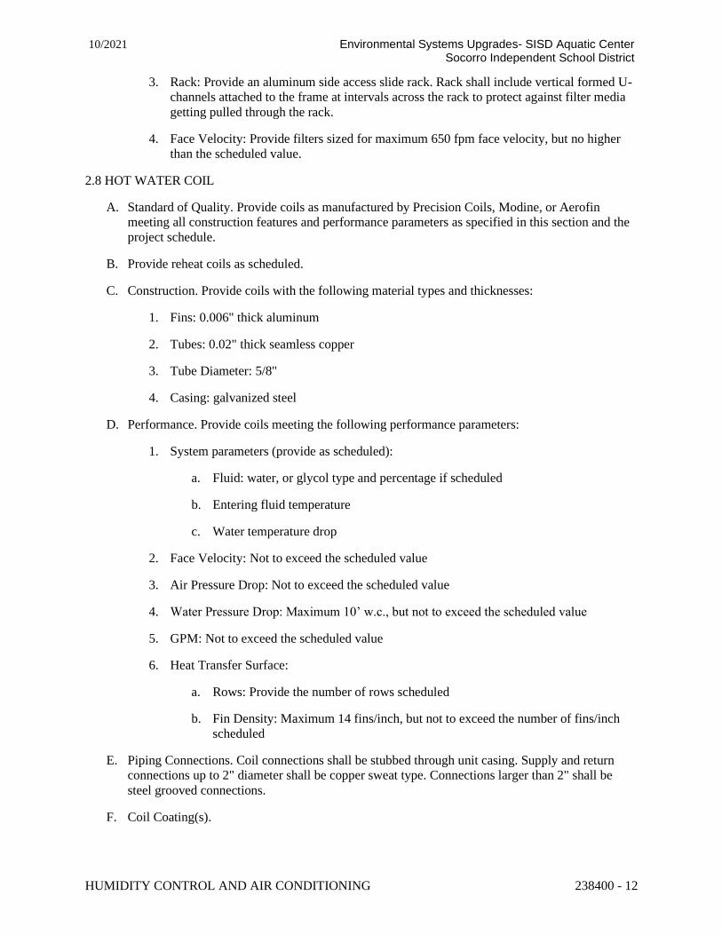
HUMIDITY CONTROL AND AIR CONDITIONING 238400 - 12
10/2021 Environmental Systems Upgrades- SISD Aquatic Center Socorro Independent School District
3. Rack: Provide an aluminum side access slide rack. Rack shall include vertical formed U-
channels attached to the frame at intervals across the rack to protect against filter media
getting pulled through the rack.
4. Face Velocity: Provide filters sized for maximum 650 fpm face velocity, but no higher
than the scheduled value.
2.8 HOT WATER COIL
A. Standard of Quality. Provide coils as manufactured by Precision Coils, Modine, or Aerofin
meeting all construction features and performance parameters as specified in this section and the
project schedule.
B. Provide reheat coils as scheduled.
C. Construction. Provide coils with the following material types and thicknesses:
1. Fins: 0.006" thick aluminum
2. Tubes: 0.02" thick seamless copper
3. Tube Diameter: 5/8"
4. Casing: galvanized steel
D. Performance. Provide coils meeting the following performance parameters:
1. System parameters (provide as scheduled):
a. Fluid: water, or glycol type and percentage if scheduled
b. Entering fluid temperature
c. Water temperature drop
2. Face Velocity: Not to exceed the scheduled value
3. Air Pressure Drop: Not to exceed the scheduled value
4. Water Pressure Drop: Maximum 10’ w.c., but not to exceed the scheduled value
5. GPM: Not to exceed the scheduled value
6. Heat Transfer Surface:
a. Rows: Provide the number of rows scheduled
b. Fin Density: Maximum 14 fins/inch, but not to exceed the number of fins/inch
scheduled
E. Piping Connections. Coil connections shall be stubbed through unit casing. Supply and return
connections up to 2" diameter shall be copper sweat type. Connections larger than 2" shall be
steel grooved connections.
F. Coil Coating(s).

HUMIDITY CONTROL AND AIR CONDITIONING 238400 - 13
10/2021 Environmental Systems Upgrades- SISD Aquatic Center Socorro Independent School District
1. Reheat: Electrofin E-Coat
2.9 HOT GAS REHEAT COIL
A. Standard of Quality. Provide coils rated in accordance with AHRI 410-200 as manufactured by
Precision Coils, Modine, or Aerofin meeting all construction features and performance
parameters as specified in this section and the project schedule.
B. Construction. Provide coils with the following material types and thicknesses:
1. Fin: 0.010” thick aluminum
2. Tubes: 0.016” thick seamless copper
3. Tube Diameter: 3/8"
4. Casing: Galvanized steel
C. Performance. Provide coils meeting the following performance parameters:
1. System parameters (provide as scheduled):
a. Fluid: R-410a
2. Face Velocity: Maximum 800 fpm, but not to exceed the scheduled value
3. Air Pressure Drop: Not to exceed the scheduled value
4. Refrigerant Pressure Drop Not to exceed 3 psi
5. Heat Transfer Surface:
a. Rows: Provide the number of rows scheduled
b. Fin Density: Maximum 14 fins/inch, but not to exceed the number of fins/inch
scheduled
D. Coil Coatings: Electrofin E-Coat
2.10 DX COIL
A. Standard of Quality. Provide coils rated in accordance with AHRI 410-2001 as manufactured by
Precision Coils, Modine, or Aerofin meeting all construction features and performance
parameters as specified in this section and the project schedule.
B. Construction. Provide coils with the following material types and thicknesses:
1. Fins: 0.006" thick aluminum
2. Tubes: 0.016" thick seamless copper
3. Tube Diameter: 3/8", 1/2", or 5/8" as required
4. Casing: galvanized steel
5. Circuiting Type: Interlaced, or as scheduled

HUMIDITY CONTROL AND AIR CONDITIONING 238400 - 14
10/2021 Environmental Systems Upgrades- SISD Aquatic Center Socorro Independent School District
C. Performance. Provide coils meeting the following performance parameters:
1. System parameters:
a. Fluid: R-410a
b. Outdoor ambient temperature: 95 deg F, or as scheduled
2. Face Velocity: Minimum 250 fpm, maximum 500 fpm, but not to exceed the scheduled
value
3. Air Pressure Drop: Not to exceed the scheduled value
4. Refrigerant Pressure Drop: Maximum 13 psi
5. Heat Transfer Surface:
a. Rows: Provide the number of rows scheduled
b. Fin Density: Maximum 12 fins/inch, but not to exceed the number of fins/inch
scheduled
D. Cooling Coil Drain Pan. All cooling coils shall be provided with aluminum IAQ drain pans that
begin at the entering air side of the coil face and extend a minimum of 12” past the leaving air
side of the coil face. Entire underside of the drain pan, including the piping run to the casing
exterior, shall be coated with no less than 2” of spray foam insulation to ensure no sweating
occurs below. Coil shall be installed on “walk-on” supports spaced a maximum of 6” apart to
allow full access to the coil face without damage to the drain pan. Pans without the feature shall
not be accepted. The drain pan shall be sloped in a minimum of 2 directions to ensure proper
drainage. The drain shall be located on the bottom of the drain pan and the connection
countersunk below the surface of the drain pan to eliminate the potential for standing water at the
connection. No side connections in the pan shall be allowed. An integral intermediate drain pan
shall be provided for coils over 44" finned height in applications where condensate is expected.
The intermediate pan shall be factory piped to the main drain pan.
E. Piping Connections. All refrigerant connections shall remain inside the unit cabinet and run
directly to the condensing section.
2.11 INTEGRAL AIR COOLED REFRIGERATION
A. Integral Packaged Air Cooled Refrigeration System - General Requirements.
1. Provide a custom integral air cooled packaged refrigeration system factory piped, wired,
charged, charged, and tested with R-410a and oil.
2. Refrigeration system shall be custom designed to provide energy efficient operation for
the specific conditions of this project and performance of each unit.
3. Construction shall integrate into the unit cabinet using the same quality construction and
finishes as the cabinet (detailed in this section). Use of a manufacturer’s standard pre-
designed condensing unit or condenser shall not be accepted. Skid mounting of a standard
condenser or condensing unit from another manufacturer shall not be accepted.
4. Use of a refrigerant to water/glycol heat exchanger and fluid cooler for the condenser(s)
shall not be accepted due to lower energy efficiency (additional heat exchanger, less

HUMIDITY CONTROL AND AIR CONDITIONING 238400 - 15
10/2021 Environmental Systems Upgrades- SISD Aquatic Center Socorro Independent School District
efficient heat transfer due to a lack of phase change in the condenser and reheat coils,
inefficient glycol required for the working fluid, and the additional maintenance for
pumps, expansion tanks, air separator, and the glycol fill).
5. System shall be factory run tested. The run test shall include the following data at a
minimum for each circuit and associated compressor(s), and for both cooling and
dehumidification operation:
a. Verification of compressor crankcase heater operation (where applicable)
b. Discharge pressure
c. % of reheat capacity (where applicable)
d. Liquid pressure, temperature, and subcooling
e. Suction pressure, temperature, and superheat
f. Compressor Discharge Temperature
g. Condenser Air Temperature Rise
h. Oil level @ sight glass
i. Amp Draw, % of RLA
j. Outdoor Ambient Temperature and humidity
k. Evaporator Coil Air Temperature Drop
l. Duration of test to achieve steady state prior to data collection (20 minutes
minimum)
m. Refrigerant charge shall be adjusted as required to pass both cooling and
dehumidification test with the same charge. The run test form with pass/fail
criteria for each parameter shall be provided with the submittal. The completed
forms shall be provided with IOMs upon shipment.
6. Submittal shall include all features as detailed in this section.
B. Condenser Section Construction:
1. Condenser section top panel shall be 2” double wall injected foam construction for
superior strength and lower vibration. Exterior panel material and finish shall be pre-
paint. Interior panel material shall be galvanized. Fan inlets shall be connected to the
injected foam top panel.
2. Condenser coils and condenser fans for each circuit shall be separated from other circuits
by a load bearing 2” double wall injected foam panel constructed of galvanized.
3. Floor shall be 2” double wall injected foam construction with aluminum top panel. Floor
panels shall be sealed to the unit base with industrial adhesive to inhibit water leakage.
An aluminum floor pan shall overlay the injected foam panel. A provision for draining
moisture to the exterior of the unit shall be provided.
4. Hail guards/vandalism guards shall be provided for all condenser sections.

HUMIDITY CONTROL AND AIR CONDITIONING 238400 - 16
10/2021 Environmental Systems Upgrades- SISD Aquatic Center Socorro Independent School District
a. For units with angled condenser coils, screens shall be constructed of expanded
aluminum mesh secured to a formed metal frame matching the unit exterior.
Screens shall be mounted vertically to protect the coils, compressors, and
refrigeration specialties. The screens shall be removable without use of tools and
be self-retaining.
b. For units with vertical condenser coils, hail guards shall be non-removable
expanded aluminum mesh secured to a formed metal frame matching the unit
exterior.
C. Minimum System Requirements.
1. R-410a refrigerant
2. Rated Efficiency. Refer to the schedule for the minimum EER requirements for the
refrigeration system. Refrigeration systems with EER’s less than what is scheduled shall
be rejected. Provide calculations demonstrating compliance with the specified EER.
3. Custom Refrigeration System Performance. Provide all parameters demonstrating
integrated, balanced performance of the system and resultant capacity at the design
airflow including:
a. Compressor operating envelope for the compressor selected with superheat,
subcooling
b. Condenser coil details (fins/rows/fin type and thickness, tube diameter, thickness,
and type (smooth, rifled) face area, face velocity, and air pressure drop
c. Evaporator coil details (fins/rows, fin type and thickness, tube diameter,
thickness, and type (smooth, rifled) face area, face velocity and air pressure drop
d. Condenser fan airflow and horsepower
e. Refrigerant pressure drop for all components and refrigerant line velocity for all
piping runs
f. Ambient design temperature and suction and condensing temperatures at design
conditions
4. Compressor Protection. Provide temperature sensors and pressure transducers on both the
suction and discharge sides of the system, and provide active compressor control logic to
keep the compressors in the compressor manufacturer’s recommend operating envelope
(variable capacity compressors), or “three strikes” compressor protection (fixed capacity
compressors).
5. Operating Efficiency. Refrigeration system control logic shall optimize efficiency
through control of liquid pressure, condenser airflow and compressor capacity to
minimize compressor lift and maximize EER as the load on the system varies.
6. Low Ambient Operating Temperature. Refrigeration system shall be designed to operate
at a minimum outdoor air temperature of 35°F.
D. Refrigeration Circuit(s). Provide 2 independent circuits completely pressure tested, dehydrated,
and factory charged with refrigerant and oil for shipment. Final charge adjustments during
commissioning shall be provided by the installing contractor.
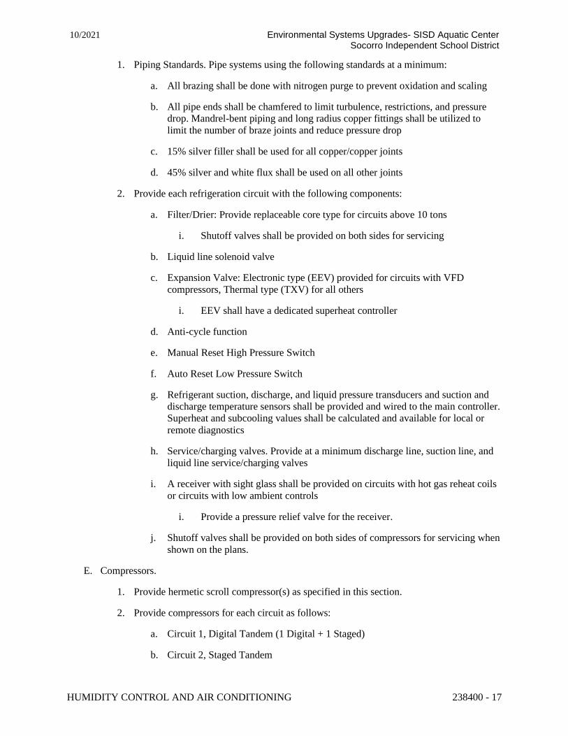
HUMIDITY CONTROL AND AIR CONDITIONING 238400 - 17
10/2021 Environmental Systems Upgrades- SISD Aquatic Center Socorro Independent School District
1. Piping Standards. Pipe systems using the following standards at a minimum:
a. All brazing shall be done with nitrogen purge to prevent oxidation and scaling
b. All pipe ends shall be chamfered to limit turbulence, restrictions, and pressure
drop. Mandrel-bent piping and long radius copper fittings shall be utilized to
limit the number of braze joints and reduce pressure drop
c. 15% silver filler shall be used for all copper/copper joints
d. 45% silver and white flux shall be used on all other joints
2. Provide each refrigeration circuit with the following components:
a. Filter/Drier: Provide replaceable core type for circuits above 10 tons
i. Shutoff valves shall be provided on both sides for servicing
b. Liquid line solenoid valve
c. Expansion Valve: Electronic type (EEV) provided for circuits with VFD
compressors, Thermal type (TXV) for all others
i. EEV shall have a dedicated superheat controller
d. Anti-cycle function
e. Manual Reset High Pressure Switch
f. Auto Reset Low Pressure Switch
g. Refrigerant suction, discharge, and liquid pressure transducers and suction and
discharge temperature sensors shall be provided and wired to the main controller.
Superheat and subcooling values shall be calculated and available for local or
remote diagnostics
h. Service/charging valves. Provide at a minimum discharge line, suction line, and
liquid line service/charging valves
i. A receiver with sight glass shall be provided on circuits with hot gas reheat coils
or circuits with low ambient controls
i. Provide a pressure relief valve for the receiver.
j. Shutoff valves shall be provided on both sides of compressors for servicing when
shown on the plans.
E. Compressors.
1. Provide hermetic scroll compressor(s) as specified in this section.
2. Provide compressors for each circuit as follows:
a. Circuit 1, Digital Tandem (1 Digital + 1 Staged)
b. Circuit 2, Staged Tandem

HUMIDITY CONTROL AND AIR CONDITIONING 238400 - 18
10/2021 Environmental Systems Upgrades- SISD Aquatic Center Socorro Independent School District
3. Compressor Technology. Compressors shall meet the following requirements:
a. Digital Scroll. Provide compressors capable of an operating range from 100%
down to 10% of the full refrigeration system capacity as manufactured by
Emerson (Copeland).
i. Provide scroll compressors with reverse rotation protection, sight glass
with moisture indicator (TXV), and oil level adjustment
ii. Provide and mount and wire the controller(s) from the compressor
manufacturer to control operation of the digital compressor(s).
iii. Compressors shall be mounted on rubber isolators
b. Fixed Speed Scroll. Piping for tandem compressors shall be engineered and
provided by the compressor manufacturer, and the performance shall be
specifically provided for the tandem set.
i. Provide scroll compressors with reverse rotation protection, sight glass
with moisture indicator (TXV), and oil level adjustment.
ii. Compressors shall be mounted on rubber isolators.
F. Condenser Coils
1. Standard of Quality. Provide copper tube/aluminum fin coils as manufactured by
Precision Coils, Modine, or Aerofin meeting all construction features and performance
parameters as specified in this section. Microchannel condenser coils shall not be used
due to the extremely dense fin spacing required and inability to repair leaks, requiring
replacement of the entire coil.
2. Construction. Provide coils with the following material types and thicknesses:
a. Tubes: 0.016 thick seamless copper w/ rifled interior
b. Fins: 0.006” thick aluminum lanced fins
c. Tube Diameter: 5/16" w/ rifled interior or 3/8" thick as required
d. Casing: Galvanized
e. Provide an integral subcooler circuit to ensure a minimum of 10 degrees of liquid
subcooling
3. Performance. Provide coils meeting the following performance parameters:
a. Condenser Design Ambient Temperature: 95°F
b. Condenser Airflow
c. Face Velocity: Maximum 600 fpm, but not to exceed the scheduled value
d. Air Pressure Drop: Not to exceed the scheduled value
e. Refrigerant Pressure Drop: Maximum 13 psi including condenser subcooler
section

HUMIDITY CONTROL AND AIR CONDITIONING 238400 - 19
10/2021 Environmental Systems Upgrades- SISD Aquatic Center Socorro Independent School District
f. Heat Transfer Surface:
i. Rows: Provide the number of rows scheduled
ii. Fin Density: Maximum 16 fins/inch, but not to exceed the number of
fins/inch scheduled
G. Condenser Fans/Motors:
1. Standard of Quality. Fans shall be Greenheck SE with construction details as specified
below.
2. Wheel. The fan wheel shall be axial type. Wheel shall be statically and dynamically
balanced.
a. The wheel shall be constructed of formed aluminum
3. Construction:
a. Motor drive frame assembly shall be formed galvanized steel channels. Fan
panels shall be galvanized steel with formed flanges pre-punched mounting
holes, and a deep formed inlet venturi. Motor shall be locked to the fan shaft
using a square key and set screw or tapered bushing.
b. Accessories: Provide powder-coated steel wire fan guard.
4. Motor. Motors shall be direct drive 1200 rpm maximum, internal rotor AC, as described
in this section:
a. Motor shall be heavy duty OPAO NEMA T-frame, 1200 RPM direct drive,
designed specifically for use in a vertical (shaft up) configuration as a condenser
fan motor. Bearings shall be permanently lubricated, double sealed ball bearings.
Motor shaft shall have a water slinger. Motor shall be variable frequency drive
(VFD) compatible. Motor shall be UL recognized and CSA listed.
5. Performance:
a. Fan motor horsepower shall not exceed the scheduled condenser fan horsepower.
b. Provide the number of fans scheduled, no exceptions.
c. Fan performance shall be tested for airflow and sound in an AMCA certified test
lab.
2.12 ELECTRICAL
A. General Requirements.
1. Units shall be provided fully factory wired per the requirements of this section.
2. Units shall be ETL listed to the Standard for Safety for Heating and Cooling Equipment,
ANSI/UL Standard 1995 and CAN/CSA C22.2 No. 236-05. Factory wiring practices,
safety provisions, components, and labeling shall be per the requirements of the ETL
listing.
3. All major electrical components shall be UL listed.

HUMIDITY CONTROL AND AIR CONDITIONING 238400 - 20
10/2021 Environmental Systems Upgrades- SISD Aquatic Center Socorro Independent School District
B. Wiring Requirements.
1. Power wiring shall be enclosed in conduit.
2. Ladder wiring diagrams shall be provided. Lines on the diagram shall be numbered, and
the associated wires shall be numbered at both terminations for help in troubleshooting.
3. Wires shall be color coded per voltage (line voltage/120V/24V) in the Electrical Panel,
and per function from the terminal blocks in the Electrical/Control panel to end devices.
Color coding shall be called out on the ladder diagram.
4. Provide units with an SCCR rating of 5kA.
5. Provide dedicated wires to end devices (transducers, analog sensors, etc.) to limit
potential electrical interference.
6. Wiring and conduit penetrations through panels or block-offs shall be provided with a
grommet per metal surface to protect against electrical short circuiting and abrasion, and
sealed with sealant to prevent leakage.
C. Major Components.
1. Non-Fused disconnect shall be provided by the unit manufacturer and mounted by the
unit manufacturer.
2. Electrical/Control Panels(s). Provide NEMA 3R panel or panels as required
a. Provide exterior panels or flush mounted enclosures as shown on the unit
drawings.
b. Provide a backplate within the panel for mounting of electrical components,
DDC controllers and expansion boards, control transformers, required fusing,
service switch, VFDs (where applicable) and terminal blocks.
3. Variable Frequency Drives shall be factory provided, wired and programmed.
a. VFDs for supply fan shall be ABB Model ACH580
b. VFDs for exhaust fan shall be ABB Model ACH580
c. A factory manual bypass shall be provided for all supply fan motors. A motor
protector shall be provided ahead of the VFD.
d. A factory manual bypass shall be provided for all exhaust fan motors. A motor
protector shall be provided ahead of the VFD.
e. Individual branch fusing per VFD shall be provided by the unit manufacturer.
f. VFD Mounting. For indoor units, mount VFDs on the unit exterior. For outdoor
units provide exterior NEMA 3R enclosure or flush mounted enclosure as shown
on the unit drawings. Provide a backplate within the enclosure for mounting of
VFDs.
4. Motor protection. Motors (including compressors) not controlled using VFDs shall have
motor starter protectors and contactors rated for the duty.

HUMIDITY CONTROL AND AIR CONDITIONING 238400 - 21
10/2021 Environmental Systems Upgrades- SISD Aquatic Center Socorro Independent School District
D. Accessories:
1. A manual reset phase loss protection relay shall be provided as part of the
compressor/refrigeration protection system. Upon sensing a loss of phase the unit shall be
de-energized.
E. Factory Refrigeration System Wiring.
1. The compressor/refrigeration protection system and associated controls shall be factory
wired.
2.13 DDC SYSTEM
A. Manufacturer shall provide a programmable digital control system for each custom unit. A user
terminal with LCD display shall provide capability of monitoring operation and changing
setpoints through an integral keypad. The user terminal shall be capable of being either unit
mounted (UUT) or remote mounted (RUT) using straight through six wire flat cable. The
manufacturer shall program the sequence of operation as specified in this section. The program
shall include the following:
1. Unit start-up and shut-down requirements including fan/airflow proving indication and
damper actuator end switch indication.
2. Temperature control for all heating and cooling devices.
3. Humidity control for all dehumidification devices and processes.
4. Economizers (dry-bulb, enthalpy, dewpoint, energy recovery) where applicable.
5. Fan controls for each mode of operation.
6. Requirements for modes of operation other than Normal Occupied mode.
7. Integration of all optional devices (firestats, smoke detectors, pressure transducers,
airflow stations, etc) specified in this section.
8. Alarms:
a. Informational auto-reset alarms shall be provided and stored for all sensors, end
devices, and components, and shall be accessible through the controller user
interface.
b. Manual reset alarms shall be provided as specified for some optional devices
(e.g. firestats, freezestats, smoke detectors, fan duct static pressure limits) and
where required to protect the space served or the equipment.
c. A list of standard alarms available to the BAS shall be included in the points list
as specified in this section.
B. The controller shall communicate with the Building Automation System (BAS) through a factory
provided BACnet MS/TP interface card. A points list necessary to control the equipment, perform
the sequence of operation, and informational points required by the BAS shall be provided as
specified in this section.

HUMIDITY CONTROL AND AIR CONDITIONING 238400 - 22
10/2021 Environmental Systems Upgrades- SISD Aquatic Center Socorro Independent School District
C. The controller shall have the capability through a web-based User Interface to remotely monitor
all inputs/outputs, control the user terminal, view status of all alarms including both alarm and
cleared time stamps, remotely upload a new program, and view historical and live log data for the
past 24 hours. The controller shall save the log data for a rolling 7 days in a csv file that can be
downloaded, with the additional capability of storing 31 days of logged data to an external thumb
drive.
D. Alarm Indication. DDC controller shall have one digital output for remote indication of an alarm
condition. (i.e. Blower current switch, differential pressure switch, damper end switch, supply
discharge low limit, freeze stat, fire stat, smoke, dirty filters…). Alarm Indication shall be
configurable to indicate only shut down alarms if desired. The type of alarm shall be
distinguishable through the BMS.
E. The Equipment manufacturer shall provide the following refrigeration system compressor
protections:
1. Cycle Time (minimum OFF and minimum ON).
2. High Saturated Discharge Temperature.
3. Low Saturated Suction temperature.
4. High Pressure Trip (manual reset).
5. Low Pressure Trip.
6. High Discharge Temperature.
F. Sequence of Operation. Manufacturer shall provide the sensors required for the Sequence of
Operation, including additional points listed in the BMS Points listed when included in this
section. The sequence of operation shall incorporate devices such as smoke detectors, filter
switches or transducers, and kill switches specified in the Electrical section of this equipment
specification.
G. BMS Points List. [Insert Standard BMS Points List from Sequence of Operation generated by the
Sequence Generator]. [Insert BMS Points List for Controls Lite if unit has Packaged
Refrigeration].
PART 3 – EXECUTION
3.1 INSTALLATION
A. Install unit per manufacturer’s recommendations and instructions as described in the Installation,
Operation and Maintenance (IOM) manual.
B. Contractor shall NOT use the units to provide temporary heating, cooling or ventilation to the
building during construction.
3.2 EXAMINATION
A. After completing the installation, inspect the air handler for damage, dirt or debris. Remove all
dirt, construction debris and repair any damage to the finish including chips, scratches or dents.
3.3 FIELD QUALITY CONTROL

HUMIDITY CONTROL AND AIR CONDITIONING 238400 - 23
10/2021 Environmental Systems Upgrades- SISD Aquatic Center Socorro Independent School District
A. After the equipment is installed, the manufacturer’s representative shall inspect the installation
and recommend any corrective actions. Do not start up the equipment until the following
operations are completed:
1. All controls are installed and fully operational.
2. Power is connected to the unit.
3. Shipping materials have been removed.
4. Filtration media is installed and clean.
5. Piping and duct connections are installed and operational.
6. Leak checks are completed on all water connections.
7. All wiring, refrigerant piping, gasketing and hardware are properly installed on any
multiple section units.
PART 4 SEQUENCE OF OPERATION
Control Application Summary:
• This P-Series unit consists of a flat plate heat exchanger, supply fan, exhaust fan, direct expansion
coil, hot water coil, hot gas reheat coil, and a unit controller. The unit controller maintains the
supply temperature set point in all modes. The supply temperature set point is reset up and down
based on return temperature drift. In dehumidification mode, the cooling is controlled to maintain
the direct expansion coil leaving air temperature and reheat is controlled to maintain the supply
discharge temperature. The supply fan provides a constant air volume set through the unit
controller. The exhaust fan is controlled to maintain a negative natatorium space pressure.
Remote On/Off:
• The unit controller shall have an input allowing the unit to be started/stopped by others.
Occupied/Unoccupied Mode:
• Occupied/Unoccupied mode shall be controlled by the BMS.
• Occupied mode:
o Supply Fan on, 100% balanced airflow.
o Exhaust Fan on, control per sequence.
o Economizer enabled.
o Dehumidification enabled.
o Heating enabled.
o Cooling enabled.
o All dampers are enabled.
• Unoccupied mode - Reduced Airflow:

HUMIDITY CONTROL AND AIR CONDITIONING 238400 - 24
10/2021 Environmental Systems Upgrades- SISD Aquatic Center Socorro Independent School District
o Supply Fan on, 67% of balanced VFD HZ, adjustable.
o Exhaust Fan on, control per sequence.
o Economizer enabled.
o Dehumidification enabled.
o Heating enabled.
o Cooling enabled.
o All dampers are enabled.
Supply Fan Control:
• The supply fan VFD shall be used for manual field balancing only.
Exhaust Fan Control:
• The exhaust fan VFD shall modulate to maintain a negative differential pressure between the pool
space and an adjacent space. Set Point: -0.04" W.C., adjustable.
• The exhaust fan VFD speed will be limited by an offset of the current outdoor damper position.
Heating:
• Heating Mode: The hot water coil is controlled to maintain the supply temperature set point.
• Heating Lockout: The hot water coil will be locked out when the outside air is > 85°F, adjustable.
Cooling:
• The economizer and mechanical cooling are controlled to maintain the supply temperature set
point. The economizer, if available, will be used as the first stage of cooling.
• Economizer Mode (energy recovery reduction type) active only if the outside air temperature <
return air temperature.
o The outside air heat exchanger face/bypass dampers modulate (bypassing outside air
around the heat exchanger) to maintain the supply temperature set point.
• Cooling Mode: The direct expansion coil is controlled to maintain the unit supply temperature set
point.
• Cooling Lockout: The direct expansion coil will be locked out when the outside air is < 50°F,
adjustable.
Dehumidification:
• Stage 1
o The outside air dampers modulate to control space dew point set point: 67°F, adjustable.

HUMIDITY CONTROL AND AIR CONDITIONING 238400 - 25
10/2021 Environmental Systems Upgrades- SISD Aquatic Center Socorro Independent School District
o When the outside air damper is at its minimum position, the recirculation air damper is at
its maximum position, and the exhaust fan VFD is at minimum exhaust (+/- space
pressure offset, described above).
• Stage 2
o The cooling is controlled to maintain the direct expansion coil leaving air temperature set
point.
o When the space dew point is above the dehumidification set point: 67°F, adjustable and
the direct expansion coil is activated for dehumidification, the DDC controller will reset
the direct expansion coil leaving air temperature set point up and down between the
values listed below in order to maintain the set point .
▪ Dehumidification coil leaving minimum set point 54.8°F, adjustable
▪ Dehumidification coil leaving maximum set point 65°F, adjustable
o Maximum outside air shall be maintained while the direct expansion coil is energized for
space dew point control (outside air damper is in its maximum position, and recirculation
air damper is in its minimum position).
• If heating is active and unable to maintain the supply temperature set point, the dehumidification
control loop shall be limited to minimum position.
Re-Heating:
• Re-Heating Mode: The hot gas reheat is controlled to maintain the supply temperature set point.
• Re-Heating Lockout: The hot gas reheat is only active when cooling is in dehumidification mode.
Supply Temperature Set Point:
• The unit controller will reset the supply temperature set point up & down between the values
listed below, in order to maintain the return temperature set point: 83°F, adjustable.
o Supply heating discharge minimum set point: 75°F, adjustable.
o Supply heating discharge maximum set point: 110°F, adjustable.
o Supply cooling discharge minimum set point: equal to the current return dew point + 2°F.
o Supply cooling discharge maximum set point: 65°F, adjustable.
Air to Air Heat Exchanger Defrost Sequence:
• The outside air heat exchanger face & bypass dampers modulate (bypassing outside air around
the heat exchanger) to maintain its leaving exhaust air temperature above the defrost set point:
38°F, adjustable.
Purge Mode:
• Purge mode shall be controlled through the BMS interface or remote switch.
• Purge mode shall be used to index the unit into maximum outside air mode for removal of
chemical off-gassing during a "pool-shocking" procedure.

HUMIDITY CONTROL AND AIR CONDITIONING 238400 - 26
10/2021 Environmental Systems Upgrades- SISD Aquatic Center Socorro Independent School District
• A digital input or a manual override on the remote user terminal can be used to energize/de-
energize the purge mode.
• In purge mode the outside and recirculation air dampers shall be modulated to their maximum
outside air position.
• Stage 1 Dehumidification overridden.
• Stage 2 Dehumidification control per sequence.
• Cooling control per sequence.
• Heating control per sequence.
• The purge mode has an adjustable "purge time limit" (adjustable on a user terminal, factory set at
180 minutes).
Master/Slave Multi-Unit Control:
• The units shall have the option to be controlled in a master/slave configuration.
• Communications between the Master and Slave unit(s) is done using Modbus TCP. A CAT5/6
cable is required and shall be terminated in a daisy chain configuration to the RJ45 switch of each
unit.
• Any unit can be a master or slave unit as set by the user through the programmable user terminal
provided with each unit. Only one master on the network.
• Each unit must have a static IP address assigned to it. The IP address(es) of the slave units shall
be entered into the programmable user terminal of the master unit.
• The slave units shall receive the following values from the master.
o Outside air dehumidification ramp.
o Space pressure ramp.
o Supply temperature set point.
• If at any time a slave unit loses communication with the master unit, it shall fall back to
standalone control.
Smoke Detector(s):
• Return and/or supply smoke detector(s), provided, installed and field wired in series, by others.
Upon detecting smoke, the smoke detector(s) shall send a single binary signal to the unit
controller to de-energize the unit.
Supply Discharge Low Limit:
• If supply discharge temperature drops below 35°F (adjustable), the DDC shall de-energize the
unit after an adjustable time delay.
Supply Discharge High Limit:

HUMIDITY CONTROL AND AIR CONDITIONING 238400 - 27
10/2021 Environmental Systems Upgrades- SISD Aquatic Center Socorro Independent School District
• If supply discharge temperature rises above 120°F (adjustable), the DDC shall de-energize the
unit after an adjustable time delay.
Phase/Voltage Monitor:
• A phase/voltage protection relay shall be provided for each unit. Upon sensing a loss of phase or
voltage, the unit shall be de-energized.
Sequence Required Sensors:
• Analog Points:
o Supply Air Temperature
o Outside Air Temperature
o Return Air Temperature
o Return Air Humidity
o Exhaust Air Temperature
o Hot Gas Reheat Leaving Air Temperature
o Flat Plate Leaving Exhaust Air Temperature
o Space Differential Pressure Sensor
• Digital Points:
o Phase/Voltage Protection Relay
Requested Additional Sensors (Monitoring Only):
• Analog Points:
o Space Air Temperature
o Space Air Humidity
o Flat Plate Entering Outside Air Temperature
o Flat Plate Leaving Supply Air Temperature
o Flat Plate Entering Exhaust Air Temperature
• Digital Points:
o Hard Wired Occupancy Input
END OF SECTION 23 84 00
Related Documents