Section 2.1 : Electrical systems : Basics review Paternité - Pas d'Utilisation Commerciale - Partage des Conditions Initiales à l'Identique : http://creativecommons.org/licenses/by-nc-sa/2.0/fr/ BRUNO GAZENGEL AND STÉPHANE DURAND

Welcome message from author
This document is posted to help you gain knowledge. Please leave a comment to let me know what you think about it! Share it to your friends and learn new things together.
Transcript

Section 2.1 :Electrical
systems : Basicsreview
Paternité - Pas d'Utilisation Commerciale - Partage des Conditions Initiales à l'Identique : http://creativecommons.org/licenses/by-nc-sa/2.0/fr/
BRUNO GAZENGEL AND STÉPHANE DURAND

Table des matières
I - Introduction 5
II - Test your prior knowledge 7
III - Definitions and conventions 11
A. Two terminal networks.................................................................................11 1. The notion of two terminal networks..................................................................................11 2. Conventions for the orientation of voltage drops and current.................................................11
B. Quadripoles (two port networks)...................................................................12 1. Notions of quadripoles (two port networks, or four terminal networks)...................................12 2. Orientation conventions...................................................................................................13 3. Relations between conventions.........................................................................................14 4. The point of conventions..................................................................................................14
Bruno Gazengel, Stéphane Durand 3
C. Complex notation in the harmonic domain......................................................15
IV - Ohms law 17
V - RLC circuits 19
A. Contents of an RLC circuit............................................................................19
B. Time domain..............................................................................................20
C. Frequency domain.......................................................................................20
VI - Notions of impedance 21
A. The notion of impedance : definition..............................................................21
B. Admittance versus Impedance......................................................................22
C. Definitions..................................................................................................22
D. Interaction generator-receiver......................................................................22
VII - Common quadripoles 25
A. Coupling equations......................................................................................25
B. The gyrator................................................................................................26
C. To know more............................................................................................27
VIII - Electrical circuit analysis 29
A. Kirchoff's Law.............................................................................................29
B. Voltage divider............................................................................................29
C. Current divider...........................................................................................30
D. Thevenin generator.....................................................................................31
E. Norton generators.......................................................................................31
IX - Conclusion 33
A. Summary...................................................................................................33
B. Test your knowledge...................................................................................33
C. Excercise 1: Series RLC circuits.....................................................................36
D. Excercise 2: Parallel RLC circuit....................................................................36
X - Bibliography 37
Introduction
Bruno Gazengel, Stéphane Durand4

I - Introduction I
ObjectiveThe aim of this section is to recall the basic governing laws of electrical circuits.
Prior knowledge neededKnowledge of basic electrical components (resistor, capacitor, inductor), voltageand currentKnowledge of the complex notation in the harmonic domain (see section 1.21).
1 - ../../Grain1.2en/index.html
Bruno Gazengel, Stéphane Durand 5

II - Test your prior knowledge
II
We recommend that you test your current knowledge. If you do not succeed, youmay need to review the basic notions (see section 1.22), or the required notions.
Exercice 1 : Test your knowledge
Question 1
What is the unit of the voltage v ?
Volt
Ampère
Coulomb
Watt
Faraday
Ohm
Joule
Question 2
What is the unit of current i ?
2 - ../../Grain1.2en/index.html
Bruno Gazengel, Stéphane Durand 7

Volt
Ampère
Coulomb
Watt
Faraday
Ohm
Joule
Question 3
What is the unit of electrical charge q ?
Volt
Ampère
Coulomb
Watt
Faraday
Ohm
Joule
Question 4
Test your prior knowledge
Bruno Gazengel, Stéphane Durand8

When a current flows between two teminals of a conductor:
There must be no voltage drop between these points
There must be a voltage drop between these points
There is a circulation of electrical charges
Question 5
What is the relation between the electrical charge and the current ?
Test your prior knowledge
Bruno Gazengel, Stéphane Durand 9

III - Definitions and conventions
III
Two terminal networks 11
Quadripoles (two port networks) 12
Complex notation in the harmonic domain 15
A. Two terminal networks
1. The notion of two terminal networks
A two terminal network is an electrical component which has two terminals. Lightbulbs, batteries, switches, resistors and motors are examples. We distinguishbetween two types of two terminal networks:
Generators: active two terminal neworks, Receivers: passive two terminal networks.
Active two terminal network
Passive two terminal network
2. Conventions for the orientation of voltage drops and current
The conventional orientation of the voltage and current is illustrated in the followingimage:
for generators, the voltage and the current both go in the same direction(left part of the figure),
Bruno Gazengel, Stéphane Durand 11

for the recievers, the current and voltage go in opposite directions (rightpart of the figure).
Conventions for the orientation of the voltage and current
B. Quadripoles (two port networks)
1. Notions of quadripoles (two port networks, or four terminal networks)
A quadripole is a system with two inputs, each one has two poles. A quadripoleallows an energy transfer between two dipoles connected to either input.The description of a dipole requires the use of four physical quantities:
The voltage drop across each input, the current entering each input.
Exemple : ExampleThe single phase electrical transformer is a quadripole.
Definitions and conventions
Bruno Gazengel, Stéphane Durand12

Single phase electrical transformer
2. Orientation conventions
There are two ways to represent a quadripole: symmetrical convention: all the currents enter the quadripole. It is therefore
seen as a recieverfrom each side (see reference 9)
Asymmetrical convention: the quadripole is seen as a system with an ouputand an input. The current enters into the left input, and exits out of the rightinput. Therefore, the receiver convention is used on the left part, and thegenerator convention used on the right (see ref 6).
Symmetrical convention
Asymmetrical convention
3. Relations between conventions
The two conventions presented above affect the connection laws betweenquadripoles.
Definitions and conventions
Bruno Gazengel, Stéphane Durand 13
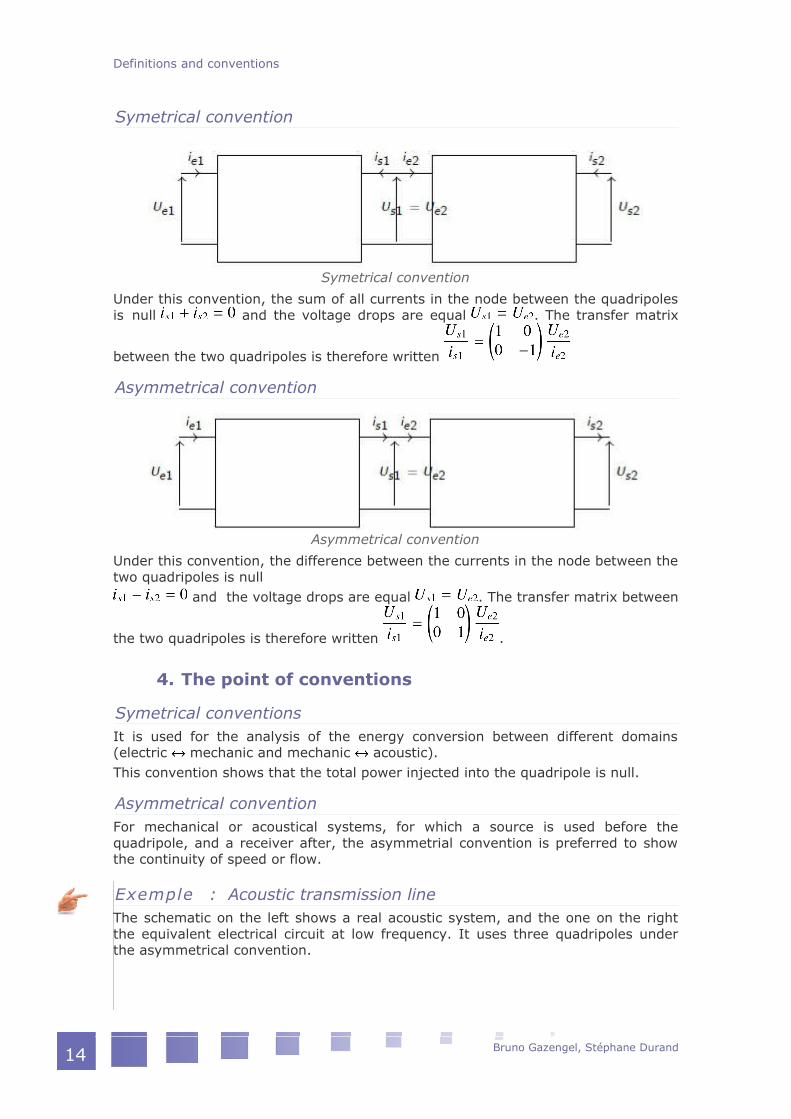
Symetrical convention
Symetrical convention
Under this convention, the sum of all currents in the node between the quadripolesis null and the voltage drops are equal . The transfer matrix
between the two quadripoles is therefore written
Asymmetrical convention
Asymmetrical convention
Under this convention, the difference between the currents in the node between thetwo quadripoles is null
and the voltage drops are equal . The transfer matrix between
the two quadripoles is therefore written .
4. The point of conventions
Symetrical conventionsIt is used for the analysis of the energy conversion between different domains(electric mechanic and mechanic acoustic).This convention shows that the total power injected into the quadripole is null.
Asymmetrical conventionFor mechanical or acoustical systems, for which a source is used before thequadripole, and a receiver after, the asymmetrial convention is preferred to showthe continuity of speed or flow.
Exemple : Acoustic transmission lineThe schematic on the left shows a real acoustic system, and the one on the rightthe equivalent electrical circuit at low frequency. It uses three quadripoles underthe asymmetrical convention.
Definitions and conventions
Bruno Gazengel, Stéphane Durand14

Acoustic transmission line
C. Complex notation in the harmonic domain
RemindersWith the hypothesis that the current and voltage are time dependant following asine law, these variables are written
for the voltage: ,
for the current: Using the complex notation (see Section 2.1, reminders: basic notions) thesebecome
for the voltage: ,
for the current: .The respective time derivatives are written
for the voltage: ,
for the current: .The respective integrals of the voltage and current can be written
for the voltage: ,
for the current: .
Definitions and conventions
Bruno Gazengel, Stéphane Durand 15

IV - Ohms law IV
In the case of an electrical resistance, the relation between the macroscopic voltageu(t) and current i(t) is Ohms law, given by:
,where R is the resistance in (Ohms).
Complément : Additional resourcesIn reality, the current that passes through the resistance increases its temperatureby the Joule effect. This in turn then modifies the value of the resistance. Theresistance is therefore time dependant, and should be written R(t).
The power dissipated by the resistance is written
Bruno Gazengel, Stéphane Durand 17

V - RLC circuits V
Contents of an RLC circuit 19
Time domain 20
Frequency domain 20
A. Contents of an RLC circuit
The RLC circuit is composed of a resistor R, an inductor (a self) L and a capacitor C.These components can be connected in series or in parallel (see the figure below).
Series RLC
Parallel RLC
Bruno Gazengel, Stéphane Durand 19

B. Time domain
The relations between voltage and current for the classic dipoles (resistor, inductor,capacitor), in the time domain, are written:
, where (t) is the current flowing through the resistor andthe voltage drop across the resistor.
, where (t) is the current flowing throught the inductor and the voltage drop across the inductor,
Symbol of an inductor
, where (t) is the current flowing through the capacitor and (t) the voltage drop across the capacitor.
Symbol of a capacitor
C. Frequency domain
Under the hypothesis that the current and voltage are time dependant following asine law, the following relations can be written using the complex notation.
For the resistor , where is the voltage drop across the resistor andi the current flowing through it,
For the inductance , where is the voltage drop across theinductor and i the current flowing through it,
For the capacitor , or, , where is the voltage dropacross the capacitance, and the current flowing through it.
RLC circuits
Bruno Gazengel, Stéphane Durand20
VI - Notions of impedance
VI
The notion of impedance : definition 21
Admittance versus Impedance 22
Definitions 22
Interaction generator-receiver 22
A. The notion of impedance : definition
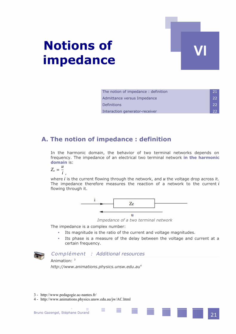
In the harmonic domain, the behavior of two terminal networks depends onfrequency. The impedance of an electrical two terminal network in the harmonicdomain is:
,where is the current flowing through the network, and the voltage drop across it.The impedance therefore measures the reaction of a network to the currentflowing through it.
Impedance of a two terminal network
The impedance is a complex number: Its magnitude is the ratio of the current and voltage magnitudes. Its phase is a measure of the delay between the voltage and current at a
certain frequency.
Complément : Additional resourcesAnimation: 3
http://www.animations.physics.unsw.edu.au4
3 - http://www.pedagogie.ac-nantes.fr/4 - http://www.animations.physics.unsw.edu.au/jw/AC.html
Bruno Gazengel, Stéphane Durand 21

B. Admittance versus Impedance
The admittance is defined as the inverse of the impedance. The electricaladmittance is written
.
Méthode : Use of the admittanceIn the case of two dual terminal networks connected in parallel, the equivalentadmittance is the sum of the admittances and of each network:
Méthode : Use of the impedanceIn the case of two dual terminal network connected in series, the equivalentimpedance is the sum of the impedances and of each of the networks:
.
C. Definitions
In the following figure, we note: the source impedance : The internal resistance of the generator (voltage or
current) which is considered ideal the load impedance : The impedance presented by the load.
The internal impedance of the generator can be measured at its output whenturned off.
Soure and load impedance
D. Interaction generator-receiver
When a generator is connected to a load, there are two way of proceeding.
Notions of impedance
Bruno Gazengel, Stéphane Durand22

Optimising the voltage transfer
The ratio should be maximum. This ratio can be written: . In thiscase ; so that .
Optimising the power transferFor the maximum power to be transmitted from the source to the load, thecalculations (detailed here,5 here6 and here7) show that the relation , where
is the complex conjugate of
Soure and load impedance
Complément : Additional resourcesA transformer can be used to modify the apparent internal impedances of thegenerator and load to maximise the power transfer.
5 - http://uel.unisciel.fr/physique/sinusoi/sinusoi_ch04/co/apprendre_ch4_06.html6 - http://en.wikipedia.org/wiki/Impedance_matching7 - http://en.wikipedia.org/wiki/Maximum_power_transfer_theorem
Notions of impedance
Bruno Gazengel, Stéphane Durand 23

VII - Common quadripoles
VII
Coupling equations 25
The gyrator 26
To know more 27
A. Coupling equations
Shown below is a virtual lossless transformer. It is used to simulate real electrictransformers for coupling effects in electroacoustics.
Ideal transformer
The equations which describe the behavior of an ideal transofrmer are:(5)
(6)where and represent the number of primary (subscript on schematic) andsecondary (subscript on schematic) windings.
Attention : CautionThe electrical impedance :
at the input of a transformer depends of the impedance at the output: :
Bruno Gazengel, Stéphane Durand 25

.
Complément : Additional resourcesAn illustration of the ideal transformer is given in this lecture8 and here9.
B. The gyrator
An ideal gyrator is a two port network whose input (respectively output) voltage(respectively output) is directly proportional to the output (respectively input)current. The ratio is usually called the "gyration resistance". In the case of thislecture, we will use the "coupling factor" (for reasons that will become apparent inthe following lectures, see section 3.210). In the case of an asymmetrical respresentation, a gyrator is illustrated by:
Gyrator
The relations between current and voltage are written:
where and represent the number of primary (subscript on schematic) andsecondary (subscript on schematic) windings.
Attention : Caution
The electrical impedance at the input of the gyrator depends on the
admittance at the output : .
C. To know more
Detailed lectures on quadripoles are given here: http://ressources.univ-
8 - http://res-nlp.univ-lemans.fr/NLP_C_M14_G02/co/Contenu_13.html9 - http://hyperphysics.phy-astr.gsu.edu/hbase/magnetic/transf.html10 - ../../Grain3.2en/index.html
Common quadripoles
Bruno Gazengel, Stéphane Durand26

lemans.fr/AccesLibre/UM/Pedago/physique/02/cours_elec/quadripo.pdf11
http://res-nlp.univ-lemans.fr/NLP_C_M14_G02/co/Module_NLP_C_M14_G02.html12
http://www.clubeea.org/uploader/mediatheque/Cours-Eln-Muret-Chap6-p217-340.pdf13
11 - http://ressources.univ-lemans.fr/AccesLibre/UM/Pedago/physique/02/cours_elec/quadripo.pdf12 - http://res-nlp.univ-lemans.fr/NLP_C_M14_G02/co/Module_NLP_C_M14_G02.html13 - http://www.clubeea.org/uploader/mediatheque/Cours-Eln-Muret-Chap6-p217-340.pdf
Common quadripoles
Bruno Gazengel, Stéphane Durand 27
VIII - Electrical circuit analysis
VIII
Kirchoff's Law 29
Voltage divider 29
Current divider 30
Thevenin generator 31
Norton generators 31
A. Kirchoff's Law
In a circuit, it is possible to calculate the voltage drops on each dipole, and thecurrent intensity in each branch of the circuit by applying the two Kirchoff laws: thenode law and the loop law.
Complément : Additional resourcesMore information14
Millman's theory is a particular form of the node law in which the currents aredescribed by the voltage drops.
Complément : Additional resourcesMore information15
14 - http://subaru.univ-lemans.fr/AccesLibre/UM/Pedago/physique/02/electri/kirchhoff.html15 - http://ressources.univ-lemans.fr/AccesLibre/UM/Pedago/physique/02/cours_elec/millman.html
Bruno Gazengel, Stéphane Durand 29

B. Voltage divider
The voltage divider is a simple electrical circuit that divides the input voltage by acertain value. This value is determined by the ratio between two resistors. Theinput voltage is applied across the two resistors and the output is taken betweenthe two resistors. The relationship between the output and input is:
Voltage divider
Complément : Additional resourcesMore information on the voltage divider here16
C. Current divider
The current divider is an electric circuit that allows the division of the input currentby a ratio of resistor values.A circuit composed of two resistors in parallel can be used to this end. The inputcurrent is applied to the circuit, and the output current flows through one of theresistors.
current divider
16 - http://subaru.univ-lemans.fr/AccesLibre/UM/Pedago/physique/02/electro/potar.html
Electrical circuit analysis
Bruno Gazengel, Stéphane Durand30

Complément : Additional resourcesMore information can be found on current dividers here17
D. Thevenin generator
The notion of equivalent Thevenin generator implies that we model a real generatorwith the perfect voltage source connected in series with a resistor whichrepresents the internal impedance of the generator. This impedance will influencethe output voltage , which will no longer be constant for any value of the load
.
Thevenin generator
Complément : Additional resourcesMore information on Thevenin generators here18
E. Norton generators
The notion of Norton generator allows us to represent an electrical source with anideal current generator connected in parallel with an internal admittance .This admittance means the output current will not be constant for every loadvalue .
17 - http://fr.wikipedia.org/wiki/Diviseur_de_courant18 - http://subaru.univ-lemans.fr/AccesLibre/UM/Pedago/physique/02/electri/thevenin.html
Electrical circuit analysis
Bruno Gazengel, Stéphane Durand 31

Norton generator
Complément : Additional resourcesMore information on Norton generators can be found here19
19 - http://subaru.univ-lemans.fr/AccesLibre/UM/Pedago/physique/02/electri/norton.html
Electrical circuit analysis
Bruno Gazengel, Stéphane Durand32

IX - Conclusion IX
Summary 33
Test your knowledge 33
Excercise 1: Series RLC circuits 36
Excercise 2: Parallel RLC circuit 36
A. Summary
The physical quantities introduced here are the voltage and the current . The relations between the basic electrical elements are the following (using
the complex notation):- For a resistor: the voltage and current are proportional .- For an inductance: the voltage follows the time derivative of the current
.- For a capacitance: the voltage follows the time integral of the current
. The impedance of an electrial system describes the reaction of a system
(voltage drop across the system) for a given current that flows through it.The impedance is a complex (magnitude, phase), frequency dependentnumber.
The admittance is defined as the inverse of the impedance. The most common electroacoustic quadripoles are the ideal transformer and
gyrator.
B. Test your knowledge
Exercice 1 : Test your knowledge
Question 1
For an inductance , the relation between the voltage and the current is
Bruno Gazengel, Stéphane Durand 33

Question 2
The impedance of a two terminal network
Is always a real number
Can be a pure imaginary number
Is the ratio of current over voltage
Is the ratio of voltage over current
Does not depend on frequency
Question 3
Association of two resistances of the same value. For two resistors in series,express the value of the total impedance
Question 4
Association of two resistances of the same value. For two resistors in parallel,express the value of the total impedance
Question 5
Association of two impedances of the same value. For two inductors in series,
Conclusion
Bruno Gazengel, Stéphane Durand34

express the value of the total impedance
Question 6
Association of two impedances of the same value. For two inductors inparallel, express the value of the total impedance
Question 7
Association of two impedances of the same value. For two capacitors inseries, express the value of the total impedance
Question 8
Association of two impedances of the same value. For two capacitors inparallel, express the value of the total impdance
Conclusion
Bruno Gazengel, Stéphane Durand 35

C. Excercise 1: Series RLC circuits
Q u e s t i o n
Write the impedance of the following system comprised of the elements , and connected in series.
Series RLC circuit
D. Excercise 2: Parallel RLC circuit
Q u e s t i o n
Write the expression of the admittance of the system comprised of theelements , a n d connected in parallel. Deduce the expression of theimpedance.
Parallel RLC circuit
Conclusion
Bruno Gazengel, Stéphane Durand36

X - Bibliography X
Jean Jacques Rousseau, Compléments d'électrocinétique, Université duMaine20 (in French)
M. Vindevoghel, M. Domon, Electrocinétique 2 : Régime sinusoïdalpermanent, cours en ligne Unisciel21 (in French)
J.J. Rousseau, Physique et simulations numériques22 (in French) J.J. Rousseau, quadripôles électriques23 (in French) Two port network, Wikipedia24
Pierre Muret, Systèmes linéaires à temps continu : quadripôles, filtrage etsynthèse des filtres, Université Joseph Fourier, Grenoble25 (in French)
20 - http://res-nlp.univ-lemans.fr/NLP_C_M14_G02/co/NLP_C_M14_G02_web.html21 - http://uel.unisciel.fr/physique/sinusoi/sinusoi/co/sinusoi.html22 - http://ressources.univ-lemans.fr/AccesLibre/UM/Pedago/physique/02/electri/rlcserie.html23 - http://ressources.univ-lemans.fr/AccesLibre/UM/Pedago/physique/02/cours_elec/quadripo.pdf24 - http://en.wikipedia.org/wiki/Two-port_network25 - http://www.clubeea.org/uploader/mediatheque/Cours-Eln-Muret-Chap6-p217-340.pdf
Bruno Gazengel, Stéphane Durand 37
Related Documents