VISUAL PERCEPTUAL CONFLICTS AND ILLUSIONS Leonard A. Temme Melvyn E. Kalich Ian P. Curry Alan R. Pinkus H. Lee Task Clarence E. Rash Vision is arguably the most important of the human senses for a Warfighter. The purpose of visual processing is to take in information about the world around us and make sense of it (Smith and Kosslyn, 2007); vision involves the sensing and the interpretation of light. The visual sense organs are the eyes, which convert incoming light energy into electrical signals (see Chapter 6, Basic Anatomy and Structure of the Human Eye). However, this transformation is not vision in its entirety. Vision also involves the interpretation of the visual stimuli and the processes of perception and ultimately cognition (see Chapters 10, Visual Perception and Cognitive Performance, and 15, Cognitive Factors). The visual system has evolved to acquire veridical information from natural scenes. It succeeds very well for most tasks. However, the information in visible light sources is often ambiguous, and to correctly interpret the properties of many scenes, the visual system must make additional assumptions about the scene and the sources of light. A side effect of these assumptions is that our visual perception cannot always be trusted; visually-perceived imagery can be deceptive or misleading, especially when a scene is quite different from those that pushed the evolution of the visual system in the past. As a result, there are situations where “seeing is not believing,” i.e., what is perceived is not necessarily real. These misperceptions are often referred to as illusions. Gregory (1997) identifies two classes of illusions: those with a physical cause and those due to the misapplication of knowledge. Physical illusions are those due to the disturbance of light between objects and the eyes, or due to the disturbance of sensory signals of eye (also known as physiological illusions). Cognitive illusions are due to misapplied knowledge employed by the brain to interpret or read sensory signals. For cognitive illusions, it is useful to distinguish specific knowledge of objects from general knowledge embodied as rules (Gregory, 1997). An important characteristic of all illusions is that there must be some means for demonstrating that the perceptual system is somehow making a mistake. Usually this implies that some aspect of the scene can be measured in a way that is distinct from visual perception (e.g., can be measured by a photometer, a spectrometer, a ruler, etc.). It is important to recognize that these “mistakes” may actually be useful features of the visual system in other contexts because the same mechanisms underlying an illusion may give rise to a veridical percept for other situations. An illusion is only an illusion if the “mistakes” are detectable by other means. While illusions may deceive the Warfigher, there are other limits of the visual system that can lead to mistakes during the conduct of a mission. These include visual masking (the reduction or elimination of the visibility of one brief stimulus, called the “target”, by the presentation of a second brief stimulus, called the “mask”), binocular rivalry (an unintentional alternation between different images presented to each eye), and spatial disorientation (a condition in which a Warfighter’s perception of position and motion does not agree with reality). Visual Masking Visual masking usually refers to the influence of one visual stimulus on the appearance of another visual stimulus, with one or the other or both stimuli being transient. Since, as this discussion will make clear, visual masking 12

Welcome message from author
This document is posted to help you gain knowledge. Please leave a comment to let me know what you think about it! Share it to your friends and learn new things together.
Transcript

VISUAL PERCEPTUAL CONFLICTS AND ILLUSIONS
Leonard A. Temme Melvyn E. Kalich Ian P. Curry Alan R. Pinkus H. Lee Task Clarence E. Rash Vision is arguably the most important of the human senses for a Warfighter. The purpose of visual processing is to take in information about the world around us and make sense of it (Smith and Kosslyn, 2007); vision involves the sensing and the interpretation of light. The visual sense organs are the eyes, which convert incoming light energy into electrical signals (see Chapter 6, Basic Anatomy and Structure of the Human Eye). However, this transformation is not vision in its entirety. Vision also involves the interpretation of the visual stimuli and the processes of perception and ultimately cognition (see Chapters 10, Visual Perception and Cognitive Performance, and 15, Cognitive Factors). The visual system has evolved to acquire veridical information from natural scenes. It succeeds very well for most tasks. However, the information in visible light sources is often ambiguous, and to correctly interpret the properties of many scenes, the visual system must make additional assumptions about the scene and the sources of light. A side effect of these assumptions is that our visual perception cannot always be trusted; visually-perceived imagery can be deceptive or misleading, especially when a scene is quite different from those that pushed the evolution of the visual system in the past. As a result, there are situations where “seeing is not believing,” i.e., what is perceived is not necessarily real. These misperceptions are often referred to as illusions. Gregory (1997) identifies two classes of illusions: those with a physical cause and those due to the misapplication of knowledge. Physical illusions are those due to the disturbance of light between objects and the eyes, or due to the disturbance of sensory signals of eye (also known as physiological illusions). Cognitive illusions are due to misapplied knowledge employed by the brain to interpret or read sensory signals. For cognitive illusions, it is useful to distinguish specific knowledge of objects from general knowledge embodied as rules (Gregory, 1997). An important characteristic of all illusions is that there must be some means for demonstrating that the perceptual system is somehow making a mistake. Usually this implies that some aspect of the scene can be measured in a way that is distinct from visual perception (e.g., can be measured by a photometer, a spectrometer, a ruler, etc.). It is important to recognize that these “mistakes” may actually be useful features of the visual system in other contexts because the same mechanisms underlying an illusion may give rise to a veridical percept for other situations. An illusion is only an illusion if the “mistakes” are detectable by other means. While illusions may deceive the Warfigher, there are other limits of the visual system that can lead to mistakes during the conduct of a mission. These include visual masking (the reduction or elimination of the visibility of one brief stimulus, called the “target”, by the presentation of a second brief stimulus, called the “mask”), binocular rivalry (an unintentional alternation between different images presented to each eye), and spatial disorientation (a condition in which a Warfighter’s perception of position and motion does not agree with reality). Visual Masking Visual masking usually refers to the influence of one visual stimulus on the appearance of another visual stimulus, with one or the other or both stimuli being transient. Since, as this discussion will make clear, visual masking
12
Chapter 12 492
occurs all the time in the real world, it certainly plays a key role in the use of visual displays and can therefore be expected to affect the use of heads-up (HUDs) and head-/helmet-mounted displays (HMDs). The following discussion uses two classic experiments to describe the general features of visual masking. Following the discussion of these experiments, some implications of visual masking are generalized to new and evolving display technologies. In the visual masking literature the visual stimulus causing masking is typically referred to as the masking stimulus (MS) or by some other term that emphasizes its masking properties. Similarly, the visual stimulus whose appearance the MS alters is typically referred to as the test stimulus (TS) or by some other term that similarly emphasizes its susceptibility to the effects of the MS. Most commonly, the MS and TS are flashed on and off with some defined temporal relation between them. If the MS and/or TS do not vary over time but have essentially unlimited exposure durations, the dependence of the TS appearance on the MS is usually considered to be due to a class of visual mechanisms that are different from masking such as simultaneous contrast. Moreover, the MS and the TS invariably have defined spatial characteristics; that is, they are not uniform illuminations of the visual field. In masking experiments, changes in the appearance of the TS can be used to assess the effects that the MS has on the visual system. To this extent, visual masking experimental methodologies are often indirect; that is, although the experiment records a defined visual characteristic of the TS, what is really of interest is the visual effect of the MS. For example, some studies refer to the MS as a conditioning stimulus or conditioning flash and treat the TS as little more than a probe of the affects of the MS on the sensitivity of the visual system. For such studies a common measure is the minimum TS luminance required for its detection. Such studies usually make the implicit assumption that TS threshold luminance at the retinal location reflects that location’s sensitivity1. Masking by light – Crawford masking The first of the two experiments to be discussed is the classic study published in 1947 by Crawford. The MS in this study was a homogeneous, circular 12° diameter light flashed on for 0.524 second every 7.2 seconds. The TS was a circular spot of light with a diameter of 0.5° that was flashed for 0.01 seconds and that was spatially centered in the MS. The task was to measure the minimum amount of light needed in the TS to detect it. These threshold measurements for one subject are in Figure 12-1, which shows TS threshold brightness as a function of time relative to the onset of the MS. The dotted vertical lines at 0 and at 0.524 seconds mark the MS onset and offset, respectively. Positive numbers indicate time after the onset of the MS while negative numbers indicate time before the onset of MS. The three different functions plotted show the results for three different levels of MS brightness. While the three functions look similar, the greater the MS brightness, the more clearly defined is the function. The results show that TS threshold is a complex function of time. Despite the fact that MS brightness is constant over its duration, the sensitivity of the visual system, as reflected by the threshold of the TS in the center of the homogeneous MS, changes over time. Consider the brightest MS: The most obvious characteristic of this function is the peak of the TS threshold near MS onset, and the rise of the TS threshold near MS offset. Between these two peaks, the TS threshold changes over the MS exposure; falling rapidly over the first 100 ms or so of the MS exposure, then more slowly until it starts to rise again, approximately 50 ms before the MS offset. After MS offset, TS threshold falls, first relatively rapidly then more gradually out past the measured time window. The most surprising aspect of the data is that TS threshold begins to increase approximately 100 ms before the onset of the MS. From one perspective, these results are very surprising since they clearly show that the MS affects visual sensitivity apparently before MS onset. This effect – that the MS operates backward in time – usually is called backward masking and has been well replicated under many conditions. It should not be over-
1 Such methodologies typically make several implicit assumptions. An example of another is that the threshold is determined by the most sensitive visual process operative at that retinal location.

Visual Perceptual Conflicts and Illusions 493
Figure 12-1. Typical Crawford-type masking data (Crawford, 1947). The x-axis is time in seconds, where 0 time is the onset of the conditioning stimulus. The y-axis is the threshold brightness of the test flash. Each of the three different functions shows data for conditioning stimulus of a different brightness. The dotted vertical lines show the onset and offset of the conditioning stimulus.
looked that a similar backward effect on visual sensitivity occurs just before MS offset, but to a lesser degree. Crawford suggested: “There seem to be two possible explanations. Either the relatively strong conditioning stimulus overtakes the weaker test stimulus on its way from retina to brain and interferes with its transmission; or the process of perception of the test stimulus, including the receptive processes in the brain, takes an appreciable time of the order of 0.1 sec., so that the impression of a second (large) stimulus within this time interferes with perception of the first stimulus.” During the more than 60 years since this report, the theoretical bases of such backward masking effects have been elaborated in great detail. But to be fair, similar masking phenomena had been well studied through the early nineteenth century with a very sophisticated understanding of what they imply about visual neural function. Metacontrast and paracontrast About six years after Crawford’s classic paper, Alpern (1953) reported a completely different kind of masking that used the visual stimulus arrangement in Figure 12-2. The stimuli were vertically-oriented rectangular bars of light that were each 2.5° by 0.5°. The TS was the bar in the middle. The MS was the pair of flanking bars. These three bars were presented to the right eye of the test subjects. The bar identified as the standard stimulus (SS) above the TS was presented to the left eye. Since the components of the stimulus array were distributed between the two eyes in this experiment, it was critical for the study to keep the eyes properly aligned. The little stimulus light, ‘z’, which was midway between the SS and the TS, was illuminated all the time and served as the fixation stimulus to help the subject minimize voluntary eye movements. Also, since z was seen by both eyes it helped the two eyes stay properly aligned. The four rectangular bars that formed the stimulus pattern of interest were presented as flashes of 5 ms duration. The variable was the time interval between the flash presentation of the TS and SS pair and the MS. The issue is the effect of the MS on the apparent brightness of the TS as a function of the temporal interval between the TS and the MS. The apparent brightness of the TS is measured by setting TS brightness to be equal to that of

Chapter 12 494
the SS, which, as mentioned, was presented in the other eye, simultaneously with the TS.2 The results are summarized in Figure 12-3.
Figure 12-2. The stimulus configuration used in the metacontrast study by Alpern (1953). The SS (standard stimulus) was presented to the left eye, the TS and MS were presented to the right eye. The MS consisted of the pair of rectangular lights that flanked the TS. Stimulus z was presented to both eyes to help the two eyes to stay aligned by providing a fixation target. Stimulus z was on all the time while all the other stimuli were flashed for 5 ms. The SS and TS were presented at the same time. The task was to set the luminance of the TS to match the SS. The experiment investigated the affect of the interval between the MS and the flash presentation of the TS and SS.
The ordinate scale is the brightness of the TS and the abscissa is the time interval between the onset of the TS and the MS; i.e., the flash onset asynchrony. Note that higher values on the ordinate reflect greater masking effects since the TS must be made brighter to match the constant brightness of the SS. It is important to note that the convention for plotting time on the abscissa in Figure 12-3 is the reverse of the convention used by Crawford, Figure 12-1. In Figure 12-3, positive time indicates that the TS occurred before the MS. Hence, the major effects that Alpern is showing are all backward in time. This figure contains eight different curves showing the effect of increasing MS brightness on visual masking. With the brightness of the MS set low (either 0.1 or 3.6 foot-Lamberts (ft-L)), the subject set the TS to about 11 foot-Lamberts (ft-L) for all temporal intervals between the MS and the TS. In other words, the TS and SS seemed about equally bright regardless of the flash onset asynchrony. The fact that the data are all about 11 ft-L for all time intervals indicates negligible visual masking when the MS are dim. On the other hand, consider the top curve which shows the TS brightness matches to the 11 ft-L SS when the MS was 3,000 ft-L. When the TS preceded the MS by about 125 ms, the TS had to be set to about 400 ft-L to match the SS of 11 ft-L. This indicates substantial masking since the TS had to be made nearly 40 times brighter to match the constant SS. Furthermore, for these stimuli, masking effects are convincingly evident out to almost 300 ms, which is 60 times longer than the duration of the MS itself. In other words, the brightness of the TS is being modulated by a MS that occurs almost 300 ms later in time and that falls on a completely different part of the retina. Admittedly, there is a great difference in brightness between the MS and the SS (3000 ft-L vs. 11 ft-L), but Figure 12-3 also plots the masking function when the MS and SS are equally bright, 11 ft-L. For those stimuli, the TS has be to about 100 ft-L to match the SS of 11 ft-L. Under these conditions the masking function peaks about 75 ms, and lasts to something between 150 to 175 ms.
2 The assumption is that masking between the two eyes is minimal with the presupposition that much of the masking phenomena are retinal. In fact, however, other research has shown that substantial masking does occur between the two eyes.

Visual Perceptual Conflicts and Illusions 495
Figure 12-3. The brightness match between the TS and the SS as a function of the temporal interval between the TS and the MS. Note positive time intervals indicate that the TS occurred before the MS whereas negative time intervals indicate that the MS occurred before the TS.
These data illustrate a visual backward masking effect most widely known in the vision science community as metacontrast. The typical earmarks of metacontrast are that the MS and TS stimulate non-overlapping parts of the retina, that the peak masking occurs when the MS follows the TS by about 100 ms or so, and that the time course of the masking function is greatly influenced by the specifics of the experiment. Alpern’s data in Figure 12-3 also illustrate this last point. The peak of the masking function tends toward larger intervals as the luminance of the MS increases. Figure 12-3 illustrates another important type of masking, often called paracontrast, which in some respects is more akin to the Crawford-type masking. When the MS precedes the TS, the apparent brightness of the TS is also reduced to some extent. This can be seen for the data plotted over the interval from 0 to -100 ms. The magnitude of the paracontrast is a fraction of that of metacontrast and would certainly not be convincingly shown by Alpern’s data. But because paracontrast has been so convincingly demonstrated in other research, it is reassuring to see evidence of it in these data. The data in Figure 12-3 illustrate that the shape of the metacontrast and paracontrast masking functions depend on the luminance of the MS. The literature generalizes this observation but the magnitude and time course of masking depends on more just the MS luminance; they depend on the specifics of the stimulus parameters as well as the response used to measure masking. In general, para- and metacontrast functions tend to be roughly either monotonic (smoothly rising or falling as a function of MS luminance) or U-shaped. Monotonic functions are sometimes called Type A while the U-shaped functions are called Type B (Kahneman, 1968). This means that the plot of TS visibility as a function of the interval between the TS and MS can take on a number of shapes. The metacontrast data in Figure 12-3 clearly show a typical U-shape or Type B function. The small size and variability of the paracontrast data obscure the shape of the functions but there is some indication for both Type A and B functions. One of the major issues masking research continues to address is the clarification and understanding of the processes that give rise to the one or other type of function. In general, studies that require discrimination or

Chapter 12 496
detection of features of the TS show different time functions than studies that record changes in TS appearance, brightness, or contrast, which, in turn, are different from functions determined simply by responses to whether or not the TS occurred. On one hand the plethora of different functions might seem to indicate uncontrolled variables, noise, or other experimental or methodological problems. On the other hand, since the results are orderly, researchers in general consider the spectrum of masking functions that different response criteria produce to be indicative of the kinds of information processing the neural visual system performs. There are now several highly quantitative models of para- and metacontrast published elaborating on known neuroanatomy and physiology (Bachmann, 1994; Breitmeyer, 1984; Breitmeyer and Ogmen, 2006). Pattern masking A third, important class of masking studies should be mentioned. These use a MS that incorporates some sort of spatial pattern. The MS structure may be a random noise pattern, an alphanumeric array, or an array of bars or gratings, or some other non-homogeneous spatial distribution appropriate for the purposes of the study. Underlying the use of such structured masking is the notion that the TS contains information and after the TS is turned off, the visual system continues to process the TS information. For example, the visual system can be expected to process a 5-ms long TS of the letter ‘D’ for longer than the 5-ms duration of the TS. Pattern masking procedures are considered to be a way of blanking or controlling the continued neural trace of the brief TS, following the idea laid out by Crawford’s comment quoted earlier (pg 285): “… the process of perception of the test stimulus, including the receptive processes in the brain, takes an appreciable time of the order of 0.1 second ..., so that the impression of a second (large) stimulus within this time interferes with perception of the first stimulus.” Based on such pattern masking research, it is now commonly recognized that a visual stimulus produces a neural trace and that this neural trace is available and recognized after the external stimulus has been turned off, as though the trace serves as an input buffer. This visual phenomenon is often referred to as an iconic memory.3 Masking – A final word Visual masking may seem to be a rather esoteric concern of vision neuropsychophysiology yet Bachmann surveyed 15 years of the “most authoritative, most cited psychology journals publishing on general problems of psychology, psychophysiology, information processing, and perception. ... among all the articles published within this period masking as a scientific topic was studied almost in 3% of the articles and masking as the method helping to study some scientific problem was employed in 11% of the articles (pg 11).” Clearly visual masking continues to be an important active area of research. Backward masking is intrinsically interesting because it describes how information is conducted through the nervous system. The two book-length reviews of visual masking by Breitmeyer and the book by Bachmann are excellent introductions to the rich literature of this area of research. To put visual masking into perceptive for its implications in the real world, cockpits, simulations, virtual reality displays, HMDs, and so forth it is helpful to remember that the time course of masking is short, only in the order of hundreds of mss. But the shortness of the masking effects does not make masking unimportant. Instead, masking seems to be fundamental to the way our visual system works. Every time the eye sees something, that something is masking what the eye had just seen the previous instant. The time domain of visual masking is the time domain of eye movements. Every eye movement involves visual masking. Current display technology enables a form of masking that is essentially new and for which there is little if any research. This masking has to do with the display of information on a transparency or a surface that appears to be
3 Iconic memory is a type of very short-term visual (or sensory) memory. An analogous memory for sound is called echoic memory, which can be defined as very brief sensory memory of some auditory stimuli.

Visual Perceptual Conflicts and Illusions 497
transparent. An example would be a HUD or HMD. On one hand, the concern historically has been whether the symbology obscures the view of the world behind it. The deeper question here is the extent to which the world behind obscures the symbology. After all, the view of the world, which is visually intricate and complex and full of all the visual information the world contains, is the background on which the symbology is presented. Any motion of the HUD or HMD relative to the world creates transients in the background relative to the superimposed, less transient symbology. The relevant question is the extent to which the visibility of the superimposed symbology is affected by the transients in the background. In this situation, the background is the MS and the foreground is the TS. The issue is more than just the summation of luminance and a reduction of contrast; the issue is the effects on visibility of the continuous presence of transients in the background MS (Harding and Rash, 2004). The same situation is increasingly common with computer displays. Web pages now display information on textured backgrounds. The information (TS) or the background (MS) may be stationary, may move, or even flash. The TS may be any gradation between an opaque overlay to a transparent one. These display technologies create environments that our visual system has not previously encountered. Since this form of masking derives from new technology, the human visual system may not have evolved biological mechanisms to process these masking effects. Our normal masking functions appear to have evolved confronting opaque surfaces rather than transparencies. It is possible that visual masking mechanisms that underlie our information processing may work in exactly the wrong way for handling (e.g., filtering) the kinds of masking effects that these new technologies create, obscuring rather than enhancing information. Binocular Rivalry An HMD can present information to one eye (monocular HMD) or both eyes (biocular or binocular HMD). When using HMDs, it is very common to have dissimilar imagery presented to the two eyes. As a result, there can be a state of competition between the two image representations in the brain. This can result in one representation being suppressed while the other forms a conscious percept (Winterbottom et al., 2007). This selective processing can alternate over time, resulting in a condition referred to as binocular rivalry. There are a number of possible bistable perceptual representations of the visual world, sometimes called bistable stimuli (i.e., having two distinct presentations) (Andrews et al., 2005; Howard, 2002 and 2005; Leopold et al., 2005; Wade, 2005). These include monocular bistable stimuli, such as transparent three-dimensional (3-D) objects, figure ground reversals, ambiguous figures, and images with dissimilar color and orientation (Figure 12-4), and biocular/binocular bistable stimuli, which can lead to binocular rivalry (Figure 12-5).
Figure 12-4. Monocular bistable stimuli: (a) Necker cube, (b) Rubin's vase versus face figure, (c) Boring's old lady versus young woman figure, and (d) Monocular rivalry, in which two physically superimposed patterns that are dissimilar in color and orientation compete for perceptual dominance (from Blake and Logothetis, 2002).

Chapter 12 498
Figure 12-5. These figure pairs can be free-fused by crossing one’s eyes and looking at a point between and just in front of the figures to be fused. The left and right figures in each pair will be brought to awareness alternately. Also apparent will be a combination or fragmented patchiness between the formations of stable single figures. The number pair is adapted from Blake (2001). The gratings are from Blake (2008).
In order to see a single, fused object viewed using two eyes, it is not necessary that the two images be identical. In fact, we use image differences in various ways to enhance perception of the visual world (Cutting and Vishton, 1995; Wagner, 2006). A close object viewed from the different angles provided by two eyes allows objects to be viewed as 3-D, a resolution of the perspective differences. The perception of layout in both personal space and action space is facilitated by binocular disparity (Cutting and Vishton, 1995). A number of studies using both gratings and small letter contrast sensitivity show binocular enhancement of visual acuity (~10%) and contrast (~40%) (Blake and Levinson, 1977; Blake, Sloan and Fox, 1981; Cagenello, Arditti and Halpern, 1993; Campbell and Green, 1965; Rabin, 1995). There is also a significant increase in brightness of objects viewed binocularly (Crozier and Holway, 1938; Lythgoe and Phillips, 1938). Although there is considerable latitude in our ability to reconcile images that are different in content or at different retinal locations in the two eyes and to capitalize on image differences, there are limits to the degree and kinds of differences that can be resolved into a stable, single, fused percept. The brain devotes significant processing power to avoid seeing double (diplopia). How the human brain handles these image differences and, in particular, how this relates to HMDs is important to HMD designs and applications. Binocular rivalry is a major concern when using monocular HMDs, particularly when one eye is free to view the user’s surrounds (Figure 12-6). However, binocular rivalry can also be a problem when using biocular or binocular HMDs, as when symbology presented to one eye overlays a view of the outside world (through a see-through HMD) seen with both eyes (Figure 12-7), as when symbology presented to one eye overlays an intensified image or forward-looking infrared (FLIR) image of the outside world presented to both eyes, when partially-overlapping images are used to expand the total HMD field-of-view (FOV) (Figures 12-8 and 12-9), or when images to the two eyes are misaligned. There are two aspects to binocular rivalry. The first is binocular. Humans, like other primates and a number of mammalian predators, have eyes in the front. This setup is used to produce a 3-D perception of the world derived from the fusion of two 2-D images. This is important for manipulating near objects and representing action space (Cutting and Vishton, 1995). Herd animals and dolphins have eyes on the sides of their heads, providing a more
Visual Perceptual Conflicts and Illusions 499
Q-SightTM (BAE Systems)
Simulated view of a scene viewed while using the Q-SightTM HMD. No suppression is depicted.
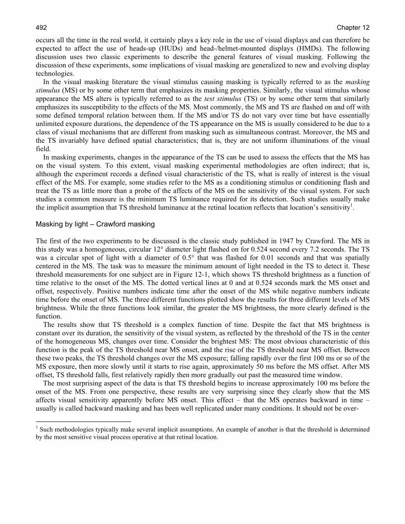
Figure 12-6. The monocular Q-SightTM (top) is a HMD system developed and manufactured by BAE Systems. Pilots using this system at night with image intensification (I2) or FLIR imagery will suppress an image from one eye, while attending to the image from the other. This ability, however, is not perfect and unexpected alternations do occur. When this type of see-through system is used during the daytime, without FLIR, a complex background with high contrast and high spatial frequencies that can be binocularly fused will tend to decrease rivalry with the symbology, although it will not necessarily eliminate it (Patterson et al., 2007).
global view (perspective) but depend largely on combining monocular cues to represent a 3-D world view. They are often very sensitive to motion and direction of objects. Much of the human brain is tied up in resolving image difference and local ambiguities from the two eyes to produce a remarkably robust, effortless visual representation of the world (Leopold et al., 2005). Andrews, Sengpiel and Blakemore (2005), in paraphrasing Hermann von Helmolz, pointed out that when constructing a perceptual representation of the visual world, the brain has to cope with the fact that any given 2-D retinal image could be the projection of countless object configurations in the 3-D world. Second, rivalry occurs when the brain cannot resolve the images from the two eyes into a fused, single percept. This is elegantly described by Tong, Meng and Blake (2006):
• “During binocular rivalry, conflicting monocular images compete for access to consciousness in a stochastic, dynamical fashion. Recent human neuroimaging and psychophysical studies suggest that rivalry entails competitive interactions at multiple neural sites, including sites that retain eye-selective information. Rivalry greatly suppresses activity in the ventral pathway and attenuates visual adaptation to form and motion; nonetheless, some information about the suppressed

Chapter 12 500
stimulus reaches higher brain areas. Although rivalry depends on low-level inhibitory interactions, high-level excitatory influences promoting perceptual grouping and selective attention can extend the local dominance of a stimulus over space and time. Inhibitory and excitatory circuits considered within a hybrid model might account for the paradoxical properties of binocular rivalry and provide insights into the neural bases of visual awareness itself.”
TopOwl™ biocular/binocular HMD with 100% overlap
Left eye view Right eye view
Figure 12-7. The TopOwl™ (top) is a biocular/binocular HMD with 100% image overlap manufactured by Thales. It is currently being used by military helicopters in several countries. The simulated views of the left and right eyes, as shown, are identical and can be free-fused. This is typical when the image is generated by a single sensor (e.g., nose-mounted FLIR), but not when using I2 tubes mounted on the sides of the helmet, which produce images from different perspectives. Symbology overlay, as depicted, is to one eye only. With the TopOwl™ system monocular or biocular symbology overlays are optional. As with monocular displays, a high contrast background with high spatial frequencies can reduce, but not eliminate binocular rivalry with symbology presented to one eye. As the contrast and higher spatial frequencies of the background lessen, as it can with low contrast I2 images, the problem of rivalry can increase (Patterson et al., 2007a).
Visual Perceptual Conflicts and Illusions 501
Helmet Integrated Display Sight (HIDSS) with partial-overlap
Combined left and right eye image
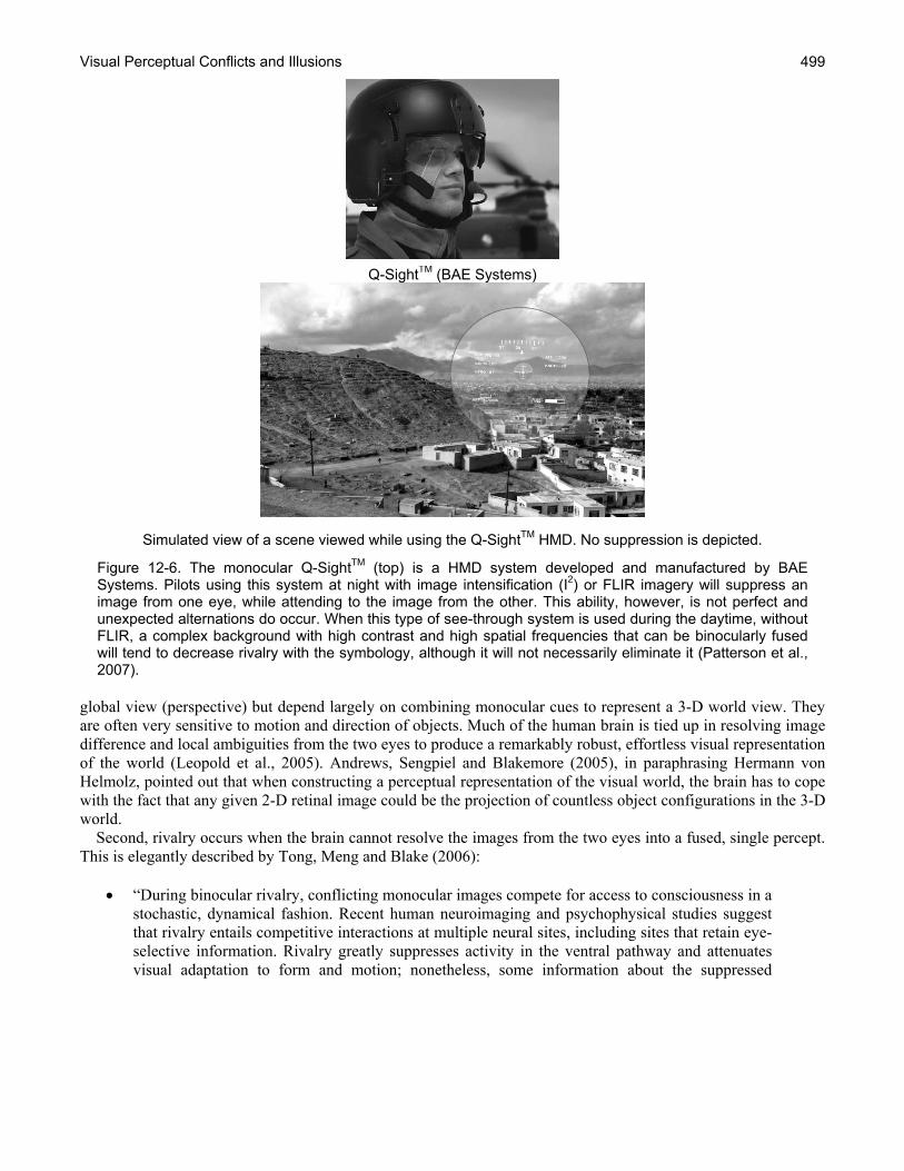
Figure 12-8. The HIDSS was a prototype partial-overlap HMD developed by Rockwell-Collins-Kaiser for the Comanche helicopter project. The image depicted here has a simulated 45% over-lap that would be biocular or binocular. The symbology is within this area. As with a HMD with full-overlap, the symbology can be presented to one or both eyes. Optically there is no border between the biocular/binocular and monocular portions of the full image. However, a form of rivalry called luning can occur, forming a perceived boundary between the two regions (Klymenko et al., 1994a).
Two of the major parallel visual geniculotstriate neural pathways, from the retina to the lateral geniculate nucleus (LGN) and from the LGN to the striate visual cortex, are the magnocellular (M) pathway and the parvocellular (P) pathway (see Chapter 6, Basic Anatomy sand Physiology of the Human Eye). The M and P neural pathways go from retina to the lateral geniculate nucleus and the striate visual cortex in the brain. The M pathway fibers originate from retinal rod photoreceptor cells and the P pathway fibers from cone photoreceptor cells. Information from the M pathway goes to the parietal lobe of the brain involved in processing "where" object-events happen. Neural cells along this pathway are particularly sensitive to movement and lower spatial frequencies associated with overall shapes of objects. Information from the P pathway goes to the inferotemporal lobe of the brain and is involved in the "identification" of objects. The neural cells along this pathway are particularly sensitive to color, the higher spatial frequencies or fine detail of objects, and contrast object contours. There is considerable evidence that image conflicts in the P pathway lead to rivalry, and image conflicts in the M pathway generally do not (He, Carlson and Chen, 2005).
Chapter 12 502
A major debate has emerged in binocular rivalry research community. It is basically about a top-down versus a bottom-up model (Andrews, Sengpiel and Cohen 2005; Blake, Westendorf and Overton, 1980; Crewther et al., 2005). Andrews, Sengpiel and Cohen (2005) represented the debate as follows:
“Two general theories have emerged. One possibility is that visual information is suppressed by inhibitory interactions prior to or at the stage of monocular confluence. In this concept, changes in perception would be mediated by shifts in the balance of suppression between neurons selective for one or another monocular image. Since these interactions must occur early in the visual pathway (e.g., the lateral geniculate nucleus or layer 4 of primary visual cortex), any changes in the activity of neurons in higher visual areas, would be explained by a loss of input, perhaps equivalent to closing one eye. The alternative hypothesis is that rivalry reflects a competition between different stimulus representations. This would be comparable to the viewing of other bistable stimuli, such as the vase-face stimulus, and as such would be relevant to the resolution of ambiguity in normal viewing.”
The general consensus is that binocular rivalry occurs at multiple stages of visual processing (Alais and Blake, 2005; Blake and Logothetis, 2002; Tong et al., 1998). It should be pointed out that there are many parallels between the study of binocular rivalry (and related ambiguous figures) and attention. There is both evidence and speculation that they all may reflect common, general neural mechanisms that influence the perceptual content of conscious awareness (Freeman, Nguyen and Alais, 2005). There is an extensive literature on binocular rivalry. Currently, a comprehensive bibliography is maintained by Robert O’Shea (2009) of the University of Otago, New Zealand. Equally informative is a binocular rivalry demonstration website maintained by Randolph Blake (2008) of Vanderbilt University, Nashville, TN. There also are a number of excellent reviews of binocular rivalry and its impact with the use of HMDs (see Alais and Blake, 2005; Blake, 2001; Hershberger et al., 1975; Howard, 2002; Laramee and Ware, 2002; Klymenko et al., 1994a,b; Patterson et al., 2007; Winterbottom et al., 2007). The most familiar result of binocular rivalry is the alternation in consciousness of competing images from the two eyes. The dominant image cannot be held indefinitely (Blake, 2008). Binocular rivalry suppression takes time to develop, on the order of 200 ms; a single fused image containing both fusable and rivalrous features can form, too quickly be followed by rivalry of the incongruous features. Eye sighting dominance probably has little impact on the length of time an image is retained in consciousness (Howard, 2002; Rash, Verona and Crowley, 1990; Rash et al., 2002). Over an extended viewing time, the rate of alternations generally slows. Image alternation is not strictly periodic, with durations generally following a Gamma distribution (Blake, 2008). There are many factors that influence alternation, but average duration of dominance generally remains constant, whereas the average duration of suppression varies inversely with stimulus strength; weak patterns tend to remain suppressed longer, increasing overall predominance of the stronger image, i.e., percentage of total viewing time (Blake 2008). The depth of suppression, loss of visual sensitivity, is on the order of 0.3 to 0.5 log units. Hershberg et al. (1975) reviewed the then-current literature on binocular rivalry and HMDs. They also performed a number of studies, including a determination of ambient scene predominance using a HMD based on contour strength variables. They defined predominance as the percentage of total viewing time during which a rivalrous image was perceived at a visibility of 90% or more. They found significant predominance effects for: 1) ambient scene complexity, 2) HMD resolution, 3) HMD luminance, 4) ambient scene luminance, 5) HMD FOV, and 6) HMD contrast. These remain key binocular rivalry variables in HMD design and use. As relative strength of competing patterns are determined by variables such as contour density, pattern contrast, spatial frequency content, and motion (Blake, 2008), it is clear that the quality of images, as defined by blur, contrast, and high spatial frequency content have an impact on the occurrence and duration of the dominant percept.
Visual Perceptual Conflicts and Illusions 503
There is evidence that cognitive factors can influence binocular rivalry alternation (Leopold et al., 2005; Freeman, Nguyen, and Alais, 2005; Patterson et al., 2007). This has fueled the bottom-up versus top-down debate regarding the neural mechanisms in binocular rivalry. Clearly, figure identity, a high order of visual processing, can be a significant factor in alternation of ambiguous figures. However, the issues in binocular rivalry are not clear-cut, where possible feed-forward and feed-back mechanisms (retroinjection to striate cortex) produce complexity (Blake, 2008; Crewther et al., 2005; de Weert, Snoeren and Konig, 2005). Blake (1988) used dichoptic presentation of meaningful and nonmeaningful text. He found no special effect of meaningful text on rivalry. As Helmholz observed, intentional effort to maintain a dominant stimulus was effective but did not prevent alternation (Patterson et al., 2007; Blake, 2005). Chong and Blake (2006) demonstrated that both exogenous and endogenous attention could increase stimulus strength of a dominant stimulus, thereby increasing its predominance. Patterson et al. (2007), in reviewing the impact of cognitive factors on binocular rivalry, concluded that attention, while having an effect on alternation, did not have a large effect, only by as much as 50%. The impact of Gestalt grouping, particularly when the features of the rival stimulus and the neighboring features form a coherent, global pattern, can increase predominance (Alais, and Blake, 1999; de Weert, Snoeren and Konig, 2005; Engel, 1956; Kovacs et al., 1997; Lee and Blake, 1999). Papathomas, Kovacs and Conway (2005) suggested that a model for Gestalt organization factors may be somewhere between top-down and bottom-up. Fusion of an image is both independent of binocular rivalry and tends to counter its occurrence (Blake and Boothroyd, 1985; Patterson et al., 2007). Fusion takes precedence over rivalry, a particularly important factor in see-through monocular HMDs with symbology superimposed on an outside scene. However, this consideration interacts with many other variables, including contrast, contour density, color, and spatial frequency content of the competing images. Another aspect of binocular rivalry is seen with partial-overlap binocular HMDs. Partial-overlapping is a technique used to expand the total FOV of binocular HMDs (see Chapter 3, Introduction to Helmet-Mounted Displays). A common portion of the angular regions seen by each eye is fused into a single percept, i. e., viewed binocularly. The right and left portions of the total FOV, flanking the fused binocular region, are viewed monocularly. Luning can develop at the transition between the two, probably a rivalrous, subjective darkening crescent area at the binocular-monocular border (Figure 12-9). This border region can be an area of reduced visibility for visually foveated objects. This is more pronounced with divergent than convergent overlap and with smaller angular regions of binocular overlap. Divergent overlap is when the monocular area imaged on each retina is from the same side as the imaging eye, whereas convergent overlap is where the monocular area imaged on each retina is from the side opposite from the imaging eye. Klymenko et al. (1994a, b) performed a series of experiments to determine factors affecting the visual fragmentation, phenomenal segregation of the total FOV into two distinct monocular areas and a binocular area. They concluded, along with other researchers, that luning is more pronounced with the divergent mode than the convergent mode. They confirmed that luning could be reduced by placing a “competing edge in the monocular field of the informational eye in order to strengthen it relative to the monocular field border of the noninformational eye. They speculated that blurring the border with the ‘noninformational eye would also weaken luning. As stated by Patterson et al. (2007), binocular rivalry does have a negative impact on visual performance, including increased reaction time and missed information/signals. They went on to say that observers (using HMDs) are not always aware of these decrements in performance. Much of the information regarding visual performance with HMDs has been gained through pilot surveys (Patterson et al., 2007; Heinecke et al., 2008; Hiatt et al., 2004; Rash, and Martin, 1988; Rash et al., 2004; Rash et al., 2002). While this literature has detailed and high-lighted problems users have with the monocular design of

Chapter 12 504
Figure 12-9. The border between the biocular/binocular central portion of a partial-overlap HMD and the flanking monocular sections can have a crescent shaped area of diminished visibility called luning, probably a variation of binocular rivalry. This area of reduced visibility can obscure objects in the field-of-view (Klymenko et al., 1994a, b).
the Integrated Helmet and Display Sighting System (IHADSS) deployed in the AH-64 Apache helicopter (Figure 12-10), surveys cannot separate out causes of visually related performance issues like undetected drift, estimates of rate of closure, slant detection, nor is it an effective medium for separating out factors like attention, monocularity, and poor image quality that can confound the relationship between reported performance issues and binocular rivalry. Despite these factors, Rash et al. (2002) found 64.4% of AH-44 Apache aviators using the IHADSS system reported unintentional alternations during flight. Most of the aviators surveyed (74.5%) reported being able to switch their attention easily from one eye to the other, and 44.9% reported having developed a strategy to aid switching such as closing one eye, glancing away, or blinking both eyes. One pilot reported “retinal rivalry when there is too much ambient light”; another reported that "If a bright light suddenly comes into view your unaided eye will dominate;” and yet another pilot reported “Binocular rivalry can occur at any time. We just deal with it (e.g. momentarily close one eye).” Most surveys of visual issues with the IHADSS were conducted during peace time. However, Heinecke et al. (2008) surveyed Apache aviators using the IHADSS during urban combat in Operation Iraqi Freedom. Their results generally paralleled those from other surveys. There was, however, on striking result that was unexpected. The incidence of problem reports was down. It would seem that the stress of combat directed attention away from equipment-user-problems and towards the task of simply making the equipment they had perform as well as possible. The Heinecke et al. (2008) report and others importantly demonstrate that humans are adaptable and find ways to make things work and new ways to apply technology. Making a monocular HMD work, with all its problems, binocular rivalry being one, is a case in point. The IHADSS has had a long, successful history and weathered several changes in military mission. The history of the individuals who have used it should provide encouragement for individuals trying to design new HMD systems with fewer problems that help users perform better and with greater transparency. Hyperstereopsis The human visual system is based on two visual detectors (the eyes), slightly separated in location on the front of the face. The distance between the pupils of the two eyes is known as the intraocular, and more commonly, the

Visual Perceptual Conflicts and Illusions 505
interpupillary distance (IPD). Each eye’s retina captures a separate and slightly different image of the external scene. The differences in the two retinal images are called horizontal disparity, retinal disparity, or binocular
Integrated Helmet and Display Sighting System (IHADSS)
Simulated view of a scene viewed while using the IHADSS HMD. The left (unaided eye) sees the cockpit and outside world; the right eye views a 30° (V) by 40° (H) portion of the outside world overlaid with symbology.
Figure 12-10. The IHADSS (top) is a monocular HMD system first developed by Honeywell and currently manufactured by Elbit. This system is used on the U.S. Army Apache AH-64 attack helicopter. The images above represent a daytime application of IHADSS. However, it should be noted that this system is usually used at night with a FLIR image in the HMD and a nighttime view of the cockpit and outside world available to the other eye. Under these conditions pilots learn to suppress vision in one eye, while attending to the image in the other. This ability, however, is not perfect and unexpected alternations do occur.
disparity. When processed by the brain, the result is a perception known as stereopsis, which is a binocular cue to depth perception (see Chapter 7, Visual Function). Humans generally do not notice depth in objects that are more than a few hundred feet away. This is because at this distance and beyond, the rays arriving at the eyes are essentially parallel, and the retinal disparity and binocular object perspective cues become too small to resolve. Stereopsis assists in the ability to estimate absolute distances between ourselves and an object, as well as the relative distances between two objects, i.e., which is closer. However, depth perception does not depend on stereopsis alone. Multiple visual cues are used to define our sense of depth. Both differences and similarities between two retinal images are fused and compared within the brain to produce depth perception (Hill, 2004). The cues for depth perception also may be monocular. Monocular cues include:

Chapter 12 506
• Relative size • Interposition • Geometric perspective • Contours • Shading and shadows • Monocular motion parallax
For the civilian community, the IPD, defining the separation between the two retinal images, ranges from 57 to 72 mm (1st to 99th percentile male) and has an average of 64 mm. The 95th percentile of U.S. military personnel falls within the 55 to 72mm range of IPD. The average IPD for U. S. Army males is 64 mm and 61 mm for females (Donelson and Gordon, 1991). In artificial situations where the input sources are located at greater than normal IPD, a condition called hyperstereo exists. A number of terms have also been applied to this visual condition, e.g., hyperstereopsis, tele-stereo, enhanced-stereo, etc. In many such hyperstereoscopic contexts, the separation between the (sources of the) inputs to the two eyes is referred to as the stereo baseline (distance). See Chapter 15, Cognitive Factors, for a case study discussion of an example hyperstereo HMD designs. The effect of greater-than-normal separation of the inputs to the two eyes produces very complicated and varied results that depend on the amount of separation and the point of fixation. For example, a pilot usually will perceive the near ground as if rising up to him/her. When a helicopter pilot is sitting on the ground, it may seem that ground level outside the cockpit is at chest level, causing some pilots to say it looks like they are sitting in a hole. However, distant objects may look natural. When this greater-than-normal separation of inputs to the two eyes exists, the convergence angle to an object being viewed is increased as compared to the convergence angle that exists for a “normal” IPD. This can cause the distance to a viewed object to appear shorter and the object to appear closer. This difference in perceived distance due to a change of convergence angle is depicted in Figure 12-11. For a normal interocular separation distance (i.e., IPD), the target point located at distance D subtends an angle of α. For the increased separation distance depicted for the I2 tubes in this diagram, the convergence angle (for this configuration) increases to β (top of diagram). However, the human visual system is still operating from the “assumption” of a normal IPD. As a consequence, the apparent convergence angle of β (bottom of diagram) causes the target object’s distance to be perceived as D'; D' < D, hence, the target object appears closer. The object size will appear to be approximately the same at both D and D', giving the impression that the object is smaller. In addition to objects appearing closer, another manifestation of hyperstereo is the ground appearing to slope upward, toward the observer, creating what is often described as a “bowl” or “dish” effect. While it is a commonly used analogy, it is slightly erroneous one. Figure 12-12 attempts to better render the illusion and presents it more as a “mountain top crater” effect. The observer describes the ground nearest to him as appearing closer (higher), with this exaggerated depth effect (the closer than effect) decreasing with distance away from the observer. When the helicopter is on the ground, the pilot perceives the near ground as being at chest level, while distant objects may look natural, a result of the non-linearity of the exaggerated depth perception with increasing distance from the observer. This hyperstereo effect results from an increased IPD and not from a proportional increase in the vertical dimension subtended by an object. The proportional angular impact of convergence decreases with distance, consequently making the apparent relative horizontal and vertical dimension of objects appear more and more normal. The hyperstereoscopic distortion is largely, although not entirely, a near effect that is usually manifested within a few hundred feet. A good-rule-of-thumb is that when the perspective differences of an object falls below one minute of arc, the impact of hyperstereo becomes negligible, and competing monocular depth cues become dominant.

Visual Perceptual Conflicts and Illusions 507
Figure 12-11. Diagram depicting change in perceived distance due to hyperstereo (Kalich et al., 2007).
Figure 12-12. Depiction of “mountain top crater” illusion due to hyperstereo. The preceding narrative is a superficial description of stereo vision and the special condition of hyperstereo. It is intended only to provide the background necessary to understand the impact on this phenomenon on HMD design. The concept of hyperstereo from a vision science perspective is a significantly more complicated topic. A more in-depth discussion would include rivalry of the retinal images and the potential impact of optical differences on hyperstereo effects (e.g., prism, binocular parallax, optical distortion, velocity and acceleration effects, etc.). Priot et al. (2006) provide an excellent review of the hyperstereo (hyperstereopsis) literature from an operational perspective. Thus far, hyperstereo has been described as a potentially problematic attribute. However, some atypical hyperstereo configurations (based on camera pairs with extremely wide baselines or temporal delays with a single camera) have been investigated for their possible use in aerial search and rescue, target detection, and traversing drop-off terrain tasks (e.g., Cheung and Milgram, 2000; Schneider and Moraglia, 1994; Watkins 1997).
Chapter 12 508
Studies evaluating hyperstereo vision HMD designs with hyperstereo are not new and date at least to the mid-1980s. The U.S. military has evaluated and conducted studies on several proposed designs. Additional studies have investigated the potential advantages of hyperstereo. The following is a synopsis of the more relevant studies and papers pertinent to this discussion:
• In 1990, the National Aeronautics and Space Administration (NASA) investigated hyperstereo for its potential use in improving hover-in-turbulence performance in rotorcraft (Parrish and Williams, 1990). While objective measures demonstrated some improvement in situation awareness, control activity, and hover stability, pilots reported a subjective dislike because of the exaggerated visual cues experienced.
• In 1992, the Night Vision Laboratory (currently Night Vision and Electronic Sensor Directorate), Fort Belvoir, Virginia, conducted an evaluation of the potential use of the Honeywell INVS/MONARC HMD in helicopters. The INVS was being developed in an attempt to design a night vision I2 system with lower weight and improved center of mass for fixed-wing aircraft. The objective lenses and intensifier tubes were placed on the side of the helmet with a separation approximately 4X that of normal IPD, introducing the condition of hyperstereo. The study’s objective was to compare aviator performance with INVS to performance with ANVIS. On initial concept flights in a TH-1 helicopter (modified AH-1S Surrogate trainer), pilots found the hyperstereopsis and sensor placement on the sides of the helmet to be major deficiencies during terrain flight. The vertical supports in the canopy always seemed to be within the FOV with any head movement, and under starlight conditions, the pilots rated the hyperstereo system unsafe and terminated the study except for demonstration rides (Kimberly and Mueck, 1992). The reported hyperstereo effects were characterized by intermediate and near objects appearing distorted and closer than normal. The ground was reported as appearing to slope upwards toward the observer and regions beneath the aircraft appearing closer than normal. Safety pilots noted a tendency to fly higher than normal during terrain flight.
• In 1992, the U.S. Air Force also conducted testing on potential ejection-safe HMD designs that demonstrated the hyperstereo effect under the Interim-Night Integrated Goggle Head Tracking System (I-NIGHTS) program (Grove, 1992; Gunderman and Stiffler, 1992). I-NIGHTS began as a joint Air Force/Navy development with the Navy as the designated lead. Candidate systems were designed by Kaiser Electronics, Honeywell (same as MONARC) and GEC Avionics). All three designs placed the I2 tubes at greater than normal IPD. Flights were conducted in the HC-130 (fixed-wing) and MH-53 and MH-60 helicopters. Interestingly, the final reports do not provide either the I2 separation distances for the HMDs or subject pilot IPDs. The hyperstereo effect apparently was not anticipated, as the flight performance evaluation questionnaire did not specifically ask about this effect, asking only one generalized question regarding image distortions. However, within individual comments, the helicopter pilots reported that the Kaiser HMD “slightly magnified images, creating the illusion of being lower than actual altitude. This became very apparent during landing where the pilot anticipated touchdown at the any moment while he was actually still 3-4 feet in the air.”
• In 1993, in support of the development of the Helmet Integrated Display Sight System (HIDSS) HMD for the U.S. Army’s RAH-66 Comanche helicopter, the USAARL and the U.S. Army Aviation and Technical Test Center (ATTC), Fort Rucker, Alabama, conducted a flight study which included an investigation of the effects of hyperstereopsis on aviator performance (Armbrust et al., 1993). Eight subject aviators flew 150.5 flight hours in an AH-64 Apache. Subjects performed a series of six modified ADS-33C (U.S. Army, 1989) maneuvers while wearing the ANVIS, Eagle Eye, and MONARC HMDs. These three systems represented IPD ratios (to normal) of 1X, 2X, and 4X, respectively. The effect of hyperstereo viewing on aviator performance was evaluated through the collection of quantitative (i.e., accuracy of hover, drift and heading) and subjective measures (i.e.,
Visual Perceptual Conflicts and Illusions 509
Subjective Workload Assessment Technique [SWAT], Perceptual Task Rating Scale [PTRS], and Subjective Performance Rating Scale [SPRS]). The study concluded that the effects of hyperstereo were minimal. It was stated that aviators “learned compensation strategies quickly.” However, it was noted that performance involving altitude estimation was affected to a greater extent. Overall, none of the subjective measures showed any difference in workload associated with the three systems. However, for low level tasks, data did show that the two hyperstereo HMDs were more difficult to fly than ANVIS.4
• In 1995-1996, Leger et al. (1998) conducted a two-phase flight test of an earlier configuration of the current TopOwlTM HMD, i.e., visor projection and 40-degree, fully-overlapped FOV. Sixty-six hours were flown in Phase One (40 hours at night; 77 flight hours were accumulated in Phase Two (45 hours at night). While various platforms were used, most of the evaluation was conducted on a SA 330 (Puma) test-bed platform developed for the TIGER program. The interocular separation was 240 mm, 46 mm less than that of the current TopOwlTM version, and was approximately 4X normal IPD. The independent variables in the study were distance and height above the ground. The study reported “a systematic under-estimation of distance and height, (with) pilots feeling closer and lower than they really were.” Pilots were reported to have “returned to nominal performance” after 5 to 10 hours of flight.
• In 1998, two German test reports documented flight experience with two hyperstereo HMD designs, the Knighthelm and the TopOwlTM (Hohne, 1998; German Air Force Test Center [WTD], 1998; in Priot et al., 2006). Both evaluations reported altitude evaluation errors. A later German evaluation of just the TopOwlTM concluded that: “The approximately double base distance of the objective lens[es] in relation to the eye creates a false range feeling during hover flight when evaluating the aircraft altitude. The impression gained is one of a low hovering altitude” (Krass and Kolletzki, 2001). In all three evaluations, pilots reported the ability to compensate after relatively few flight hours.
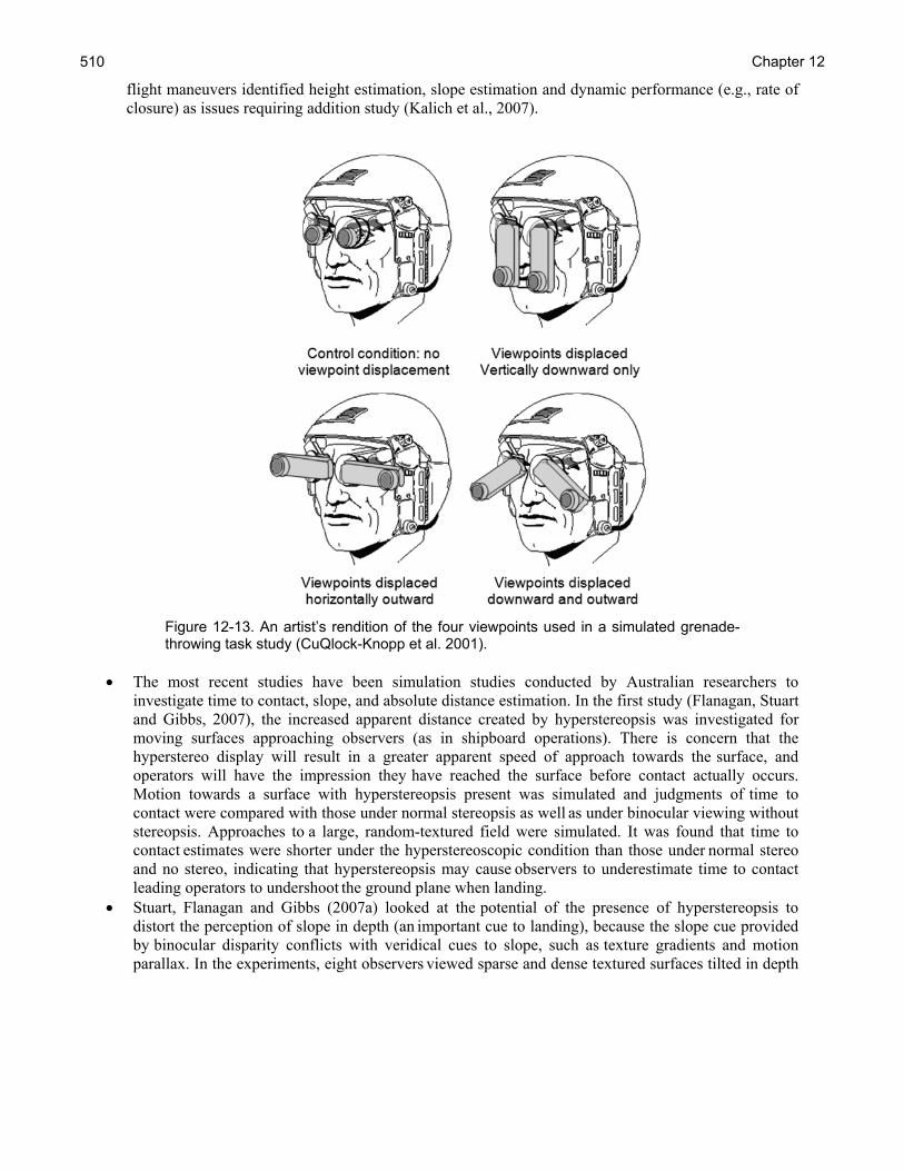
• In 2001, the U.S. Army Research Laboratory, Aberdeen Proving Ground, Maryland, conducted a study on the effects of hyperstereo viewpoint offsets of NVGs on accuracy in a simulated grenade-throwing ground task (CuQlock-Knopp et al., 2001). In the study, 32 National Guardsmen were tasked with throwing simulated grenades onto a trap-door target located 20 feet away. The measured data were the radial direction and distance from the target for each toss. Three viewpoint (hyperstereo) configurations (Figure 12-13) were compared to the normal IPD ANVIS. Only two of the three configurations presented a horizontal displacement; the third presented a vertical displacement only. The two horizontal hyperstereo distances were approximately 6.7 and 8.5 inches (170 and 216 mm), both equating to approximately 3X normal IPD. The results of the study showed that the hyperstereo resulted in a statistically significant increase in the magnitude and direction of the throwing errors.
• In 2005, the USAARL conducted a flight investigation in the UH-60 where aviators serving as the co-pilot (but not on the controls) wore the TopOwl HMD. Subjects reported an approximate 6-8 hours acclimation period that is consistent with manufacturer’s claims. However, evaluations of standard
4 One of the authors was a participant in the joint ATTC/USAARL study summarized herein. In his opinion, the reported findings did not fully capture the impact of hyperstereo on aviator performance. First, due to logistical issues, the flights were conducted under extremely benign conditions and at locations that provided too many overriding cues. Second, the AH-64 aircraft provides the least forward looking vision of any U.S. Army aircraft. This inability to look forward circumvented the potential of the pilots to accurately assess the hyperstereo effects. Third, a through review of recorded pilot comments frequently included the perception of “landing in a hole” and having to “feel for the ground.” In addition, safety pilots noted that subjects were consistently flying higher than required during terrain flight and had greater difficulty with aircraft drift. These issues were noted in the original report, but were not fully presented in the summary findings.
Chapter 12 510
flight maneuvers identified height estimation, slope estimation and dynamic performance (e.g., rate of closure) as issues requiring addition study (Kalich et al., 2007).
Figure 12-13. An artist’s rendition of the four viewpoints used in a simulated grenade-throwing task study (CuQlock-Knopp et al. 2001).
• The most recent studies have been simulation studies conducted by Australian researchers to
investigate time to contact, slope, and absolute distance estimation. In the first study (Flanagan, Stuart and Gibbs, 2007), the increased apparent distance created by hyperstereopsis was investigated for moving surfaces approaching observers (as in shipboard operations). There is concern that the hyperstereo display will result in a greater apparent speed of approach towards the surface, and operators will have the impression they have reached the surface before contact actually occurs. Motion towards a surface with hyperstereopsis present was simulated and judgments of time to contact were compared with those under normal stereopsis as well as under binocular viewing without stereopsis. Approaches to a large, random-textured field were simulated. It was found that time to contact estimates were shorter under the hyperstereoscopic condition than those under normal stereo and no stereo, indicating that hyperstereopsis may cause observers to underestimate time to contact leading operators to undershoot the ground plane when landing.
• Stuart, Flanagan and Gibbs (2007a) looked at the potential of the presence of hyperstereopsis to distort the perception of slope in depth (an important cue to landing), because the slope cue provided by binocular disparity conflicts with veridical cues to slope, such as texture gradients and motion parallax. In the experiments, eight observers viewed sparse and dense textured surfaces tilted in depth
Visual Perceptual Conflicts and Illusions 511
under three viewing conditions: normal stereo, hyper-stereo (4X magnification), and hypostereo (1/4X magnification). The surfaces were either stationary, or rotated slowly around a central vertical axis. Stimuli were projected at 6 meters (19.7 feet) to minimize conflict between accommodation and convergence, and stereo viewing was provided by a Z-ScreenTM and passive polarized glasses. Observers matched perceived visual slope using a small tilt table set by hand. Slope estimates were found to be distorted by the presence of hyperstereopsis, but to a much lesser degree than predicted by disparity magnification. The distortion was almost completely eliminated when motion parallax was present.
• The final study cited here (Stuart, Flanagan and Gibbs, 2007b) investigated the potential of increased camera separation (hyperstereo) to affect absolute depth perception, because it increases the amount of vergence (crossing) of the eyes required for binocular fusion, and because the differential
perspective from the viewpoints of the two eyes is increased. The effect of hyperstereopsis on the perception of absolute distance was investigated using a large-scale stereoscopic display system. A fronto-parallel textured surface was projected at a distance of 6 meters (19.7 feet). Three stereoscopic viewing conditions were simulated – hyperstereopsis (4X magnification), normal stereopsis, and hypostereopsis (1/4X magnification). The apparent distance of the surface was measured relative to a grid placed in a virtual "leaf room" that provided rich monocular cues, such as texture gradients and linear perspective, to absolute distance as well as veridical sterescopic disparity cues. The different
stereoscopic viewing conditions had no differential effect on the apparent distance of the textured surface at this viewing distance.
In a joint flight study between Canada, Australia and the United States, conducted in August 2008, but not yet reported, pilot interviews following an average cumulative flight time of 9 hours using the Thales Avionics TopOwlTM HMD, indicated that some level of adaptation to the hyperstereo effect may be achievable. With the exception of within 2-3 feet of the aircraft, the previously described “bowl” or “dish” effect seemed to no longer be experienced. This is a promising finding, but final analysis of the data has not been completed. The Concept of Illusions The premise underlying this section is that the phenomena usually classified as visual illusions are an essential part of normal daily vision. They are integral to what and how humans see. In fact, some vision scientists argue that much of what our visual system does under normal conditions, with all its neural machinery, may be devoted to overriding the myriad illusions that are experienced on a routine basis. The following discussion argues that visual illusions are constant, though usually unnoticed, companions to the human visual system. Operationally, vulnerability to visual illusions sets up conditions that are important for the design and use of HMDs. Just because many illusions normally go unnoticed does not mean that they are all so well-behaved in a visual world that includes HMDs. Many display technologies and strategies specifically capitalize on the propensity of the visual system to be fooled. Defining visual illusions A formal definition of visual illusions would be a logical way to start this section; but as Boring (1942) noted: “[s]trictly speaking, the concept of illusion has no place in psychology, because no experience actually copies reality…. In the sense that perception is normally dependent upon subjective factors as well as upon the stimulus, all perception is ‘illusory’ in so far as it does not precisely mirror the stimulus. In this broad sense, the term illusion becomes practically meaningless.” This point is important because the word illusion should denote more than just a failure to mirror precisely the stimulus. Gregory (1996) makes a similar point, noting that it is a lot

Chapter 12 512
easier to provide examples of different illusions and fit them into different categories than it is to provide a good definition. Nevertheless, there are at least two broad types of definitions for illusions. One type of definition notes the differences between some aspect of reality and the perception of that aspect. This type of definition emphasizes the disparity between the perception and the reality, an emphasis that seems to presuppose the existence of perceptions without such disparities, which, as Boring pointed out above, is not all that sound a premise. This type of definition also invites considerable philosophical speculation about reality and truth. Another type of definition seems to carry with it some implied explanation or mechanism, such as misperception of size, distance, shape, lighting, or color. The result is that a definition of illusions, like the illusions themselves, is a surprisingly elusive. The study of illusions5 Scientists have been systematically studying illusions since at least the middle of the 19th century. 6 These scientists have argued that illusions reveal something about how the visual system goes actually functions. At the very least, illusions may be tools for understanding the normal workings of the visual system. Like any other tool, its usefulness depends on how it is used. Certainly, in the military battlespace that includes HMDs and their symbology, visual illusions have a pragmatic importance. In essence, our interpretations of synthetic vision displays, virtual reality displays, and conformal displays are at their core visual illusions, albeit controlled ones. Proximal vs. distal stimuli In a discussion of illusions, it is important to distinguish between the physical object and the image of that object on the retina. The retinal image is sometimes called the proximal image, because that is the stimulus that is close, directly landing on the sensory receptor system and directly affecting it. The physical objects that exist in the distance, sometimes called the distal stimuli, really have no direct impact on the receptor system itself. All the visual information about the physical world and all the objects that it contains depend on the proximal, retinal image. It is on the retina that the light energy has its biological effects on the retinal photoreceptors. The visual system constructs the distal world from the retinal image, in a sense back-projecting the proximal stimulus to the world. The problem is that “… since a given state of retinal stimulation is compatible with a countless number of distal arrangements, there is necessarily an irreducible equivocally in optical stimulation that makes going from optical input to distal arrangement impossible” (Epstein, 1995). Distance perception cues A previously-made statement is that many visual illusions generally go unnoticed in daily life. It is not that they are ignored, they’re just not “seen.” For example, consider the perception of depth. The importance of having two eyes for the perception of depth is considered absolute; that each of the two eyes has a slightly different view of the world, and the disparity between the two eyes is important for seeing depth. But many of the cues for depth are actually monocular. However, humans with only one eye away can see and judge depth quite well. But the retina, upon which the optics of the eye projects that rich ménage of everything we see, is really a two dimensional surface stretched on the inside of the rear wall of the eye. There is no depth information within that image; or more precisely, there is no more depth information there than can be found on a printed page. It is true that the world is 3-D; it has depth. It is also true that our perception of the world is 3-D, i.e., containing depth
5 This section will discuss only visual illusions although all the major sensory systems – hearing, vestibular, kinesthetic, somatosensory, etc. – have demonstrated illusory phenomena. 6 J.J. Oppel is usually credited with the first systematic study of what he referred to as optical geometric illusions in: Uber geometrisch-optische Tauschungen. Jahresbericht des Frankfurter Vereins, 55, 37-47, (1854-1855).

Visual Perceptual Conflicts and Illusions 513
information. But, the interface, the retina, is flat containing no depth but just a pattern of light. Whatever depth we appreciate with one eye depends as much on illusion as does any impression of depth conveyed by relatively poorly-printed graphics on a sheet of paper. Therefore, exploring the monocular cues to depth will be instructive in understanding illusions. Monocular depth cues Interestingly, the first understanding of monocular depth cues was discovered and mastered over the centuries by artists with scientists following (surprisingly far) behind, performing the more mundane work of cataloguing, classifying, analyzing, and possibly even explaining these cues. In our discussion we will introduce briefly some of the more obvious of these monocular cues with further exploration being left to the reader via any of the standard texts on visual perception (e.g., Sekuler and Blake, 2005; Wolfe et al., 2005). Monocular depth cues can be organized in three general categories: (a) cues derived from pictorial renderings of an image on a surface like the retina, (b) cues derived from the physiological responses of the eye, and (c) cues derived from the motion of the eye. Pictorial depth cues Pictorial cues are probably the most obvious and are described by many visual perception text books and include the following:
• Linear perspective refers to the compelling impression that a pair of straight, parallel lines (like railroad tracks or highway lanes) seem to get closer together the further they are in the distance. In other words, the size of the retinal image of an object gets smaller as the object gets further away. See Figure 12-14.
Figure 12-14. Linear perspective as a monocular cue. The highway lanes appear to get closer together the further away they are.
• The relative size of known objects provides some distance information. Up to a point, one can estimate how far away someone is by how big the person’s image is. Since people are generally between five and six feet tall, seeing someone smaller than one’s thumb induces the belief that the person appears to be far away, not just tiny. See Figure 12-15.
Chapter 12 514
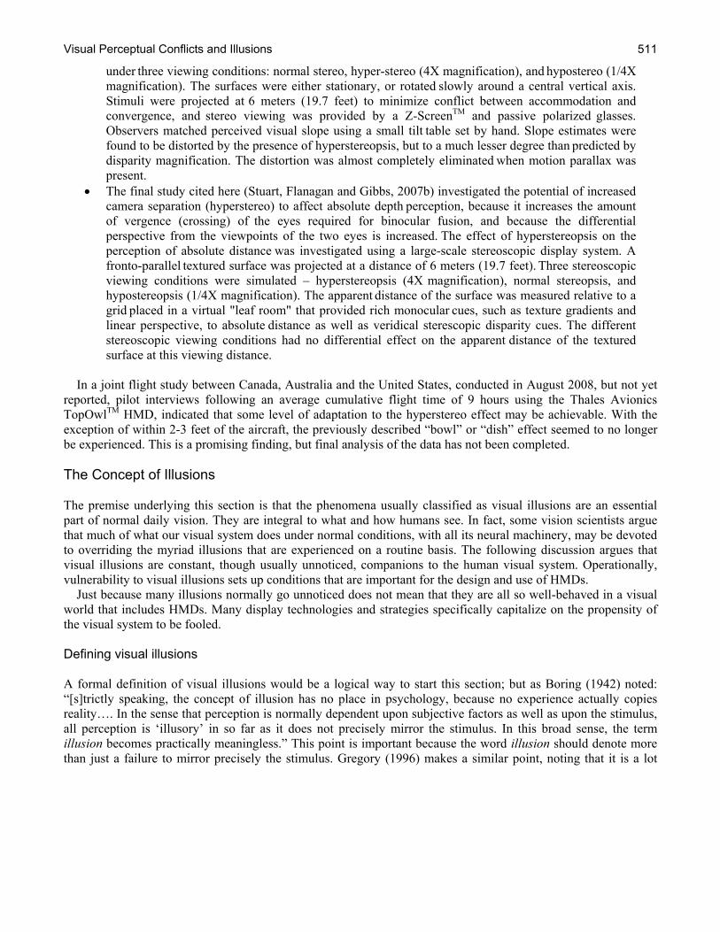
Figure 12-15. Relative size as a monocular cue. In this painting, by making the size of the people smaller, they are perceived as being further away.
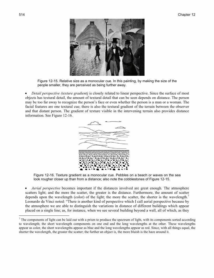
• Detail perspective (texture gradient) is closely related to linear perspective. Since the surface of most objects has textural detail, the amount of textural detail that can be seen depends on distance. The person may be too far away to recognize the person’s face or even whether the person is a man or a woman. The facial features are one textural cue; there is also the textural gradient of the terrain between the observer and that distant person. The gradient of texture visible in the intervening terrain also provides distance information. See Figure 12-16.
Figure 12-16. Texture gradient as a monocular cue. Pebbles on a beach or waves on the sea look rougher closer up than from a distance; also note the cobblestones of Figure 12-15.
• Aerial perspective becomes important if the distances involved are great enough. The atmosphere scatters light; and the more the scatter, the greater is the distance. Furthermore, the amount of scatter depends upon the wavelength (color) of the light; the more the scatter, the shorter is the wavelength.7 Leonardo da Vinci noted: “There is another kind of perspective which I call aerial perspective because by the atmosphere we are able to distinguish the variations in distance of different buildings which appear placed on a single line; as, for instance, when we see several building beyond a wall, all of which, as they
7 The components of light can be laid out with a prism to produce the spectrum of light, with its components sorted according to wavelength; the short wavelength components on one end and the long wavelengths at the other. These wavelengths appear as color, the short wavelengths appear as blue and the long wavelengths appear as red. Since, with all things equal, the shorter the wavelength, the greater the scatter; the further an object is, the more bluish is the haze around it.
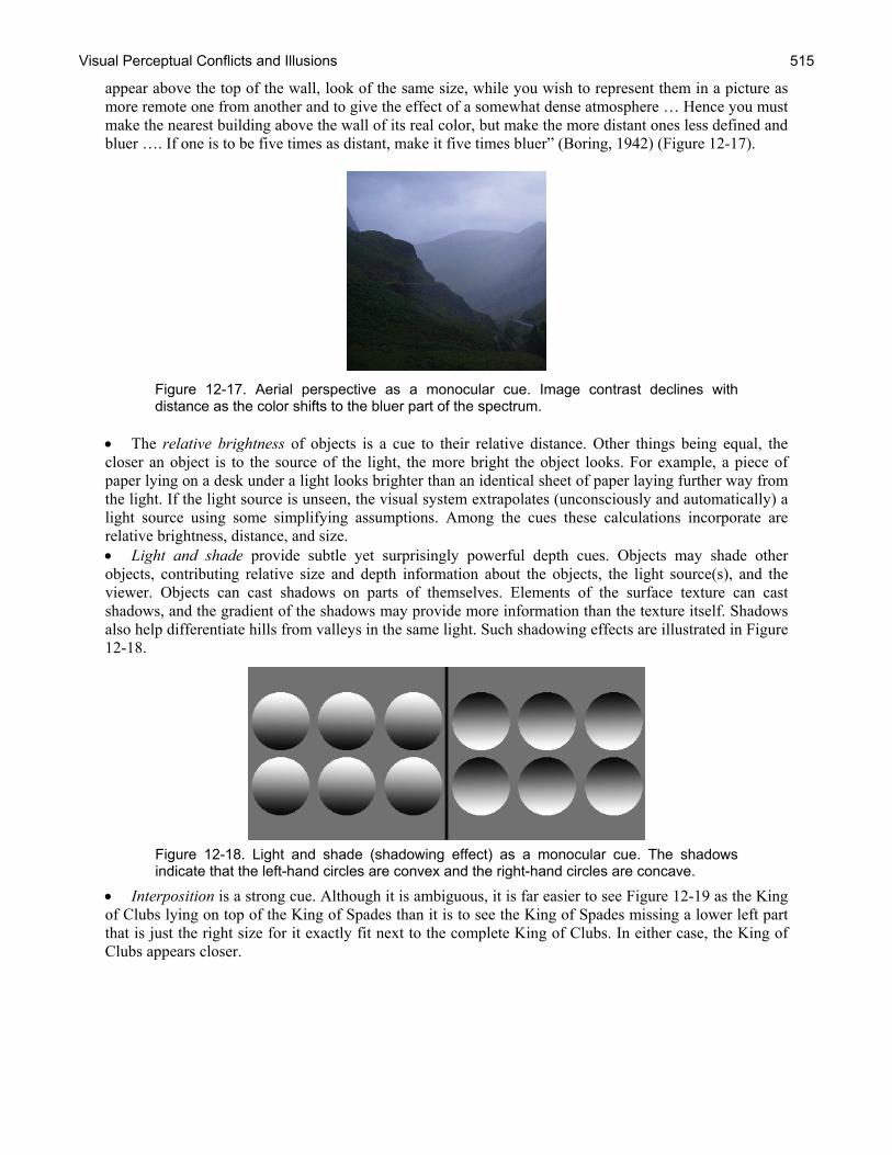
Visual Perceptual Conflicts and Illusions 515
appear above the top of the wall, look of the same size, while you wish to represent them in a picture as more remote one from another and to give the effect of a somewhat dense atmosphere … Hence you must make the nearest building above the wall of its real color, but make the more distant ones less defined and bluer …. If one is to be five times as distant, make it five times bluer” (Boring, 1942) (Figure 12-17).
Figure 12-17. Aerial perspective as a monocular cue. Image contrast declines with distance as the color shifts to the bluer part of the spectrum.
• The relative brightness of objects is a cue to their relative distance. Other things being equal, the closer an object is to the source of the light, the more bright the object looks. For example, a piece of paper lying on a desk under a light looks brighter than an identical sheet of paper laying further way from the light. If the light source is unseen, the visual system extrapolates (unconsciously and automatically) a light source using some simplifying assumptions. Among the cues these calculations incorporate are relative brightness, distance, and size. • Light and shade provide subtle yet surprisingly powerful depth cues. Objects may shade other objects, contributing relative size and depth information about the objects, the light source(s), and the viewer. Objects can cast shadows on parts of themselves. Elements of the surface texture can cast shadows, and the gradient of the shadows may provide more information than the texture itself. Shadows also help differentiate hills from valleys in the same light. Such shadowing effects are illustrated in Figure 12-18.
Figure 12-18. Light and shade (shadowing effect) as a monocular cue. The shadows indicate that the left-hand circles are convex and the right-hand circles are concave.
• Interposition is a strong cue. Although it is ambiguous, it is far easier to see Figure 12-19 as the King of Clubs lying on top of the King of Spades than it is to see the King of Spades missing a lower left part that is just the right size for it exactly fit next to the complete King of Clubs. In either case, the King of Clubs appears closer.

Chapter 12 516
Figure 12-19. Interposition as a monocular cue. The card that appears to be on top also appears closer.
Most of these monocular depth cues are rather easy to appreciate; yet some of these, such as texture gradient, light, and shade may pose more of a challenge than other cues to incorporate in HMDs, virtual reality, synthetic vision or other displays. The way these cues are implemented almost certainly affects the perception and judgment of size and distance of objects in the visual scene, how they are laid out and their relative positions (Rogers, 1995). Physiological depth cues Physiological depth cues are less apparent than the monocular depth cues, and their impact on depth perception more difficult to assess. These physiological cues depend on the muscular activity or motion of the eyes:
• Accommodation refers to the change of the focusing power of the eye as the visual system shifts attention between objects that are at different distances. The physiology of accommodation is extraordinarily elegant; coordinating lens and iris/pupil diameter changes for the two eyes. The neuromuscular system controlling these binocularly coordinated responses is driven by distance cues which most evidence suggests are calculated from the types of blur in the retinal image of the specific objects on which the eye is focused at the moment. The eye’s objective target is under conscious, higher order control, shifting from moment to moment, but the calculation of the retinal image blur in the image of the object of regard is unconscious and automatic. This rapid automatic analysis of the nature of the image blur is a depth cue to which the observer is oblivious. • Convergence refers to the pointing of the eyes’ line of sight. Each eye’s line of sight must be coordinated so the eyes are looking at the same thing. That way, the two eyes triangulate. When the eyes look at something that is close, the lines of sight converge. When the eyes look at something far away, the lines of sight are less convergent. Convergence is frequently associated with eye elevation; things that are near tend to be lower in the visual world; things that are far tend to be higher. Since accommodation, convergence, and the pupil’s response are all highly coordinated, their neuromuscular systems are closely coordinated but not identical since there is more voluntary control of the six extra-ocular muscles of each eye that determine eye pointing than there is of focusing and pupil constriction.
When the systems work, these depth cues function without being consciously noticed, but they are nonetheless important. In the context of the use of HMDs, these ocular-motor depth cues should be considered. A frequently-suggested strategy is to arrange the optical elements of the HMD so that the display approximates optical infinity. Thus, there is no relative motion between the HMD symbology and the objects seen through the HMD in the far

Visual Perceptual Conflicts and Illusions 517
distance, since they are superimposed on each other and are at the same optical distance. This strategy is based on the idea that the accommodation of the eye is at rest when the eye is focused at its far point. But some individuals apparently do not tolerate this strategy well, and its implementation becomes complicated when the users have refractive errors that need to be individually corrected. This is particularly challenging for individuals who are farsighted. It should also be noted that setting the optics of the HMD at infinity does not address whether accommodation, convergence, and pupil/iris constriction play a role in the size and distance perception of objects nor does it address any additional effects these ocular-motor responses may have on other visual illusions. Boring (1942) makes the important point that in the history of experimental psychology the monocular depth cues, although obvious, were considered secondary and less important than the binocular cues of convergence and accommodation, which were considered the primary cues for depth. The fact that accommodation and convergence require a motor response contributed to the idea that they are the primary depth cues. The motor responses provide sensory motor information about the distances of the viewed objects whereas the monocular depth cues provide information with which judgments are made. Accordingly, painting of perspective was based on the unreliability of the depth cues. Distances of remote objects depend upon the monocular depth cues; these seen distances are the result of cognitive judgments whereas the binocular depth cues, which after Wheatstone’s 1838 stereoscope, included retinal disparity (see below), were immediate and sensory. This distinction of primary and secondary depth cues may be seen as historically quaint on one hand; but on the other hand, it is reminiscent of today’s language of bottom-up and top-down distinctions. In this context, HMDs and related display compromise the primary depth cues as well as the secondary ones. Kinetic depth cues Kinetic (motion-based) depth cues are those that derive from movements an eye makes as it views the world or by objects as they approach or recede. For eye movements, these are not the accommodation and convergence motions; rather, these motions involve the translation and rotation of the eye as the head and body move through the environment. As objects in motion become smaller, they appear to recede into the distance or move farther away; objects in motion that appear to be getting larger seem to be coming closer. Using kinetic depth perception, the brain calculates a time to contact distance at a particular velocity. For example, automobile driving requires constantly judging the dynamically changing headway by kinetic depth perception. At the heart of kinetic depth is motion parallax. Motion parallax is relatively easy to demonstrate. Look at a distant object, something like a picture on the wall, close one eye, and hold up an index finger. Move your head sideways a couple of inches, slowly back and forth, so you can see the picture changing sides behind your finger. The distant picture seems to move in the same direction as your eye relative to your finger whereas your finger seems to move in the opposite direction of your eye relative to the picture. You have just demonstrated to yourself the difference between with and against motion, one of the most fundamental and important principles of geometric optics.8 This is also the basis of motion parallax. When you move through a world that contains things at a variety of distances from you, their relative with and against motions signals their relative distances. This occurs even without you consciously being aware of these relative motions. In fact, when you move around, the objects in the world look stationary, these things don’t look as though they are moving at all. It is hard to incorporate this important cue in a non-see through HMDs without incorporating some signal about the motion of the eye or head and using that signal to drive the display. If the display is in a vehicle, it may be necessary to integrate eye and/or head motion with vehicular motion to fabricate such parallax cues in a HMD.9
8 Remember how the optics of the HMD sets its symbology at optical infinity so that there is no relative motion between the symbology and the distant world on which the symbology is superimposed? There is no relative motion because they are both at the same optical distance. This is exactly the same principle. 9 Do kinetic depth cues contribute to simulator sickness in visual simulators?
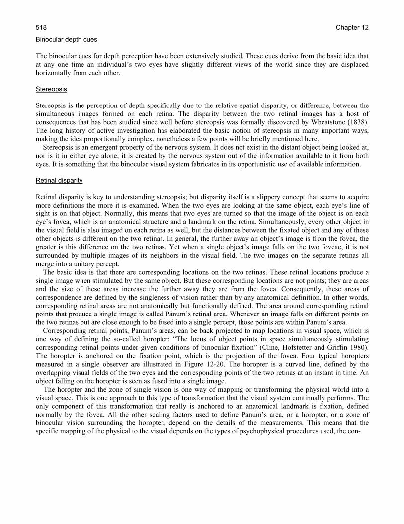
Chapter 12 518
Binocular depth cues The binocular cues for depth perception have been extensively studied. These cues derive from the basic idea that at any one time an individual’s two eyes have slightly different views of the world since they are displaced horizontally from each other. Stereopsis Stereopsis is the perception of depth specifically due to the relative spatial disparity, or difference, between the simultaneous images formed on each retina. The disparity between the two retinal images has a host of consequences that has been studied since well before stereopsis was formally discovered by Wheatstone (1838). The long history of active investigation has elaborated the basic notion of stereopsis in many important ways, making the idea proportionally complex, nonetheless a few points will be briefly mentioned here. Stereopsis is an emergent property of the nervous system. It does not exist in the distant object being looked at, nor is it in either eye alone; it is created by the nervous system out of the information available to it from both eyes. It is something that the binocular visual system fabricates in its opportunistic use of available information. Retinal disparity Retinal disparity is key to understanding stereopsis; but disparity itself is a slippery concept that seems to acquire more definitions the more it is examined. When the two eyes are looking at the same object, each eye’s line of sight is on that object. Normally, this means that two eyes are turned so that the image of the object is on each eye’s fovea, which is an anatomical structure and a landmark on the retina. Simultaneously, every other object in the visual field is also imaged on each retina as well, but the distances between the fixated object and any of these other objects is different on the two retinas. In general, the further away an object’s image is from the fovea, the greater is this difference on the two retinas. Yet when a single object’s image falls on the two foveae, it is not surrounded by multiple images of its neighbors in the visual field. The two images on the separate retinas all merge into a unitary percept. The basic idea is that there are corresponding locations on the two retinas. These retinal locations produce a single image when stimulated by the same object. But these corresponding locations are not points; they are areas and the size of these areas increase the further away they are from the fovea. Consequently, these areas of correspondence are defined by the singleness of vision rather than by any anatomical definition. In other words, corresponding retinal areas are not anatomically but functionally defined. The area around corresponding retinal points that produce a single image is called Panum’s retinal area. Whenever an image falls on different points on the two retinas but are close enough to be fused into a single percept, those points are within Panum’s area. Corresponding retinal points, Panum’s areas, can be back projected to map locations in visual space, which is one way of defining the so-called horopter: “The locus of object points in space simultaneously stimulating corresponding retinal points under given conditions of binocular fixation” (Cline, Hofstetter and Griffin 1980). The horopter is anchored on the fixation point, which is the projection of the fovea. Four typical horopters measured in a single observer are illustrated in Figure 12-20. The horopter is a curved line, defined by the overlapping visual fields of the two eyes and the corresponding points of the two retinas at an instant in time. An object falling on the horopter is seen as fused into a single image. The horopter and the zone of single vision is one way of mapping or transforming the physical world into a visual space. This is one approach to this type of transformation that the visual system continually performs. The only component of this transformation that really is anchored to an anatomical landmark is fixation, defined normally by the fovea. All the other scaling factors used to define Panum’s area, or a horopter, or a zone of binocular vision surrounding the horopter, depend on the details of the measurements. This means that the specific mapping of the physical to the visual depends on the types of psychophysical procedures used, the con-
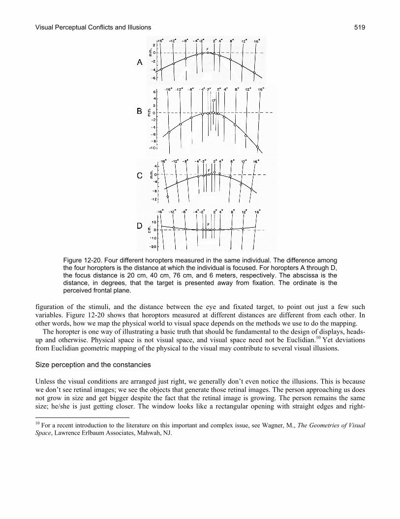
Visual Perceptual Conflicts and Illusions 519
Figure 12-20. Four different horopters measured in the same individual. The difference among the four horopters is the distance at which the individual is focused. For horopters A through D, the focus distance is 20 cm, 40 cm, 76 cm, and 6 meters, respectively. The abscissa is the distance, in degrees, that the target is presented away from fixation. The ordinate is the perceived frontal plane.
figuration of the stimuli, and the distance between the eye and fixated target, to point out just a few such variables. Figure 12-20 shows that horoptors measured at different distances are different from each other. In other words, how we map the physical world to visual space depends on the methods we use to do the mapping. The horopter is one way of illustrating a basic truth that should be fundamental to the design of displays, heads-up and otherwise. Physical space is not visual space, and visual space need not be Euclidian.10 Yet deviations from Euclidian geometric mapping of the physical to the visual may contribute to several visual illusions. Size perception and the constancies Unless the visual conditions are arranged just right, we generally don’t even notice the illusions. This is because we don’t see retinal images; we see the objects that generate those retinal images. The person approaching us does not grow in size and get bigger despite the fact that the retinal image is growing. The person remains the same size; he/she is just getting closer. The window looks like a rectangular opening with straight edges and right- 10 For a recent introduction to the literature on this important and complex issue, see Wagner, M., The Geometries of Visual Space, Lawrence Erlbaum Associates, Mahwah, NJ.

Chapter 12 520
angled corners, regardless of where we stand when we look through it. The things we look at stay constant; they don’t change. That is obvious; so obvious, in fact, that it is hard to understand why such constancy in perception is worth discussing in the first place. Obviously, it would make no sense for things to be organized any other way. After all, if we were bound to see only the retinal image rather than the object in the world, our visual world would change with every motion of the eye since every motion of the eye changes the retina image of the world. Visual perception doesn’t work that way, fortunately. The open book lying on the table slightly to one side does not look like a misshapen parallelogram; it looks, exactly like what it is, an open book and to see it as a twisted parallelogram-type figure requires an immensely artificial mental act that is more analysis than perception. This constancy of an object’s shape illustrates the constancies at work. Objects keep their size, shape, brightness, color, and so forth as we move around them, or they around us. Which is the illusion, the distal objects we see in the world, which frankly look nothing like their images on the retina, or the retinal image that is all but invisible to us, completely obscured by the constancy of objects? The retinal image is fundamentally different from the distal image; but that difference is invisible to us who sense only the ever-changing retinal image but who see only the constant distal object. Which one is real and which the illusion?11 Size constancy Size constancy is discussed briefly in Chapter 10 (Visual Perception and Cognitive performance) but is worth revisiting in the context of illusions. Certainly one of the most important studies of size constancy is that of Holway and Boring (1941), which has been discussed, replicated, analyzed, and argued about since it was first reported. For that study, a subject sat at the right angle juncture of two corridors so that the subject could look down only one corridor at a time (Figure 12-21). In one corridor, ten feet away from the subject, a white disk of light was projected. The diameter of this disk, the response disk, was adjustable. Along the other corridor other disks were presented at various distances out to 120 feet (36.6 meters), denoted stimulus disks. Each of these stimulus disks had a different, though constant, diameter. In fact, their diameters were directly proportional to their distance from the subject so that the diameters of all of the stimulus disks produced a constant 1° diameter size image on the retina. The task of the subject was to set the diameter of the response disk, at the constant 10 feet (3 meters), so that it matched the diameter of each of the stimulus disks along the corridor, out to 120 feet (3636 meters). The intensity of the light from the disks was adjusted so that the light was constant and equal at the eyes of the subject for all disks. In general, one of two types of results can be predicted. On one hand, subjects might see the different diameters of the stimulus disks along the corridor exactly as they actually were; the further away the stimulus disk, the bigger is its diameter. In this case, the large-diameter stimulus disks at greater distance along the corridor would be matched by setting the diameter of the response disk to be large. Similarly, the smaller-diameter stimulus disks at the closer distances would be matched by setting the diameter of the response disk to be small. In this case, it would be as though the subjects were using a tape measure to set the diameters. This is evidence of size constancy. On the other hand, subjects might recognize the retinal image of each of these circles is the same size, 1°, and try to set them all to that size. In this case, the subjects would be responding to the retinal image rather than to the actual physical dimensions of the stimulus disks. This would be a matter of simple trigonometry, keeping the angle constant.
11 The situation is more complicated than that because the object’s image exists independently of the retinal image, not the other way around. Consequently, the more inclusive analysis should distinguish the object from its image and from the retinal projection of that image.
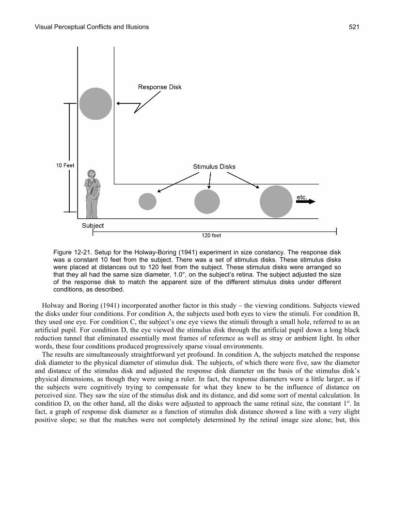
Visual Perceptual Conflicts and Illusions 521
Figure 12-21. Setup for the Holway-Boring (1941) experiment in size constancy. The response disk was a constant 10 feet from the subject. There was a set of stimulus disks. These stimulus disks were placed at distances out to 120 feet from the subject. These stimulus disks were arranged so that they all had the same size diameter, 1.0°, on the subject’s retina. The subject adjusted the size of the response disk to match the apparent size of the different stimulus disks under different conditions, as described.
Holway and Boring (1941) incorporated another factor in this study – the viewing conditions. Subjects viewed the disks under four conditions. For condition A, the subjects used both eyes to view the stimuli. For condition B, they used one eye. For condition C, the subject’s one eye views the stimuli through a small hole, referred to as an artificial pupil. For condition D, the eye viewed the stimulus disk through the artificial pupil down a long black reduction tunnel that eliminated essentially most frames of reference as well as stray or ambient light. In other words, these four conditions produced progressively sparse visual environments. The results are simultaneously straightforward yet profound. In condition A, the subjects matched the response disk diameter to the physical diameter of stimulus disk. The subjects, of which there were five, saw the diameter and distance of the stimulus disk and adjusted the response disk diameter on the basis of the stimulus disk’s physical dimensions, as though they were using a ruler. In fact, the response diameters were a little larger, as if the subjects were cognitively trying to compensate for what they knew to be the influence of distance on perceived size. They saw the size of the stimulus disk and its distance, and did some sort of mental calculation. In condition D, on the other hand, all the disks were adjusted to approach the same retinal size, the constant 1°. In fact, a graph of response disk diameter as a function of stimulus disk distance showed a line with a very slight positive slope; so that the matches were not completely determined by the retinal image size alone; but, this

Chapter 12 522
deviation was small, suggesting that not all of the distance cues were completely eliminated. In other words, under the sparsest visual conditions, the size matching approached the size of the image projected onto the retina, but not totally. Conditions B, and C produced results intermediate between the two extremes of A and D; the more rich the visual configuration, the more the subject is able to recognize the diameter and distance of the stimulus disk. The richer the stimulus environment, the more the matches were determined by the physical diameter of the stimulus disk and less by the retinal projection. Conversely, the poorer the stimulus environment, the more the matches were determined by the retinal projections of the stimulus disk and less by the physical diameter. This leads to several interesting questions regarding HMDs. What kind of visual environment confronts an operator using a HMD? How rich are the size and distance cues? Are they sufficient to support the size or distance constancies? For example, the Holway-Boring experiment was partly replicated with night vision goggles (NVGs) (Zalevski, Meehan and Hughes, 2001). The visual environment NVGs provide is not that of full daytime, but neither is the environment completely sparse. Its somewhere in between and the size judgments were consistent with that. The response disk diameters were not completely determined by the retinal image size or by the diameters of the stimulus disks; but were closer to the physical stimulus disk diameter than they were to the retinal size. The perceived sizes of an object seen with and without NVGs need not be the same. From this alone it can be expected that NVGs can affect judgments about apparent size, distance, or both. These results further suggest that it may be possible to develop a metric for the evaluation of different visual display technologies based on the extent to which they enable or degrade size constancy. Shape, brightness, and color constancies Shape, brightness, and color are some of the other constancies that contribute to our inability to see the retinal image. As demonstrated by the Holway-Boring experiment, the extent to which these constancies hold depends on the specifics of the visual stimuli. In other words, for any specific situation, the extent to which these constancies actually hold depends on the visual conditions produced by an HMD. Underlying the logic of the Holway-Boring experiment is the simple geometry of the retinal image, which may be described as the size-distance invariance hypothesis. The ratio of an object’s size to its distance defines geometrically the retinal image size of that object. The geometry of this relationship is not hypothetical; it is trigonometric. But the dependence of the perceived size of the object on this size/distance ratio is hypothetical. The whole point of the Holway-Boring experiment and its many subsequent replications (and precursors) is that the perceived size of an object need not be determined solely by the geometry that defines the retinal image size. The point is that the perceived size, as well as the perceived distance, of an object is only partly determined by the retinal image. In fact, the conditions in which retinal image size is the determining factor are extremely artificial and difficult to set up. Consequently, the importance of the retinal image size in determining the perception of an object’s size is rather small. The logic and the shortcomings of the size/distance hypothesis illustrated by the Holway-Boring experiment is analogous to the shape/slant invariance hypothesis; that a retinal projection of a given form and size determines a unique relation of apparent shape to apparent slant.12 Again, the relationship between the slant and shape depends upon the specifics of the stimulus field. At night, with little or no moon, the landing field looks like a trapezoid or parallelogram; during the day, it looks like a landing field rather than a geometric figure. The same logic applies to the color of an object, which is another of an object’s constancies. Severe disorientation would ensue if an object radically changed its color every time the lighting conditions change. Lighting changes commonly are used in theatre for dramatic effect but the colors of the objects usually do not appear to change; they appear to remain the same.
12 For an excellent review see Sedgwick, H. A.: (1988) Space perception. In: Boff, K., Kaufman, L., and Thomas, J. (Eds.), Handbook of Perception and Human Performance, (Chapter 21, pp 1-57). New York: Wiley.

Visual Perceptual Conflicts and Illusions 523
Static Illusions Visual illusions are more typically associated with geometric illusions of form or shape than with the various constancies described above. Common visual illusions typically refer to geometric illusions, ambiguous figures, illusory contours, and impossible figures. Such illusions collectively are referred to as static illusions. Geometric illusions The term “geometric illusions” refers usually to any of a class of illusions that occurs in line drawings (Robinson, 1998). These geometric illusions may be among the most commonly discussed visual illusions possibly because they are so easily illustrated. Figure 12-22 shows one version of the classic Muller-Lyer illusion. Figure 12-23 shows a few other less common geometric illusions, including the Oppel-Kundt illusion (also referred to as the filled-space illusion), which is particularly important historically. Oppel reported this illusion in 1855, in the first formal scientific investigation of this class of visual phenomena, coining the phrase “geometrisch-optische Tauschung” (translated as “geometrical-optical exchanges”) (Coren and Girgus, 1978). Since then, thousands of such graphic illustrations may have been created, with possibly nearly as many scientific papers and reports discussing them. The hope of discovering some parsimonious organization for the large universe of fascinating graphics along with simplifying or unifying explanations has been behind much of the interest and research in these geometric optical illusions. Much of the current research in this area is informed by contemporary neurophysiology and electrophysiology of the visual system and by the initiative of artificial vision.13 According to Robinson (1998), who has provided an excellent review of the field from Oppel through to the early 1970s, “It would not be too bold to claim that stimuli in the visual field almost always interact, especially if they are close together or concurrent. Thus, judgments of the degree of separation and the orientation of lines or areas are influenced by the degree of separation and orientation of other lines or areas in the visual field, especially if they are close by. This makes it easy to invent variations of illusion figures once one has appreciated the essential configuration that gives rise to the illusions.” This suggests not only that there may be an unbounded set of such illusions, but that there are certain common themes or methods by which they function. Robinson suggests three general factors, the specifics of which may differ from instance to instance.
Figure 12-22. The classic Muller-Lyer geometric static illusion in which the distance between the left and right tips of arrows is identical between the upper figure and the lower one, but appears to be longer in the latter than in the former.
The first, and possibly the most important, factor is the role of ambiguity in the illusion. The information in the graphic is just not adequate. This causes perception to vacillate among the possibilities, unable to settle on the real situation. Line drawings specifically work because they evoke rather than delimit. The second factor Robinson proposes is that the illusions evoke processes that normally lead to definitive perceptions, but the illusions fail to provide the closure necessary for a definitive percept. For example, Gregory (1996) has argued that these illusions, like the Miller-Lyer illusion, may engage perceptual processes that encode size and distance but with inadequate and indefinite stimuli. The third factor is what Robinson refers to as the visual system’s inability to 13 The theme of much of this research is to look for physiological functions that seem to mirror the perceptual phenomena. The temptation is to interpret the correlation as an explanation, an approach which has well known pitfalls.

Chapter 12 524
cope with certain input. He uses blurring as an example. To my way of thinking, these all come down to the ambiguity resulting from the sparseness of the stimulus conditions. These are the same factors or influences that underlie the various constancies discussed above; the sparseness or inadequacy of the distal stimulus or visual field result in increased perceptual ambiguities. These are the conditions that confront real operators controlling real vehicles in the real world under conditions of poor visibility.
Figure 12-23. Three different versions of the Oppel-Kundt illusion. For each version, the filled and the unfilled spaces are the same size.
Ambiguous or reversible figures Ambiguous or reversible figures traditionally have been differentiated from “geometrisch-optische Tauschungen.” The most famous of these is the Necker cube, which is illustrated in Figure 12-24 (with two additional reversible figure illusions shown in Figure 12-25 – the Mach’s book and Rubin’s vase-face illusions). According to Boring (1942), in 1832, L. A. Necker a Swiss naturalist studying crystals, noted the ambiguous reversible nature of the two-dimension drawing that bears his name. These figures, like the optical illusions described above, have been extensively studied. Some of this work has been reviewed recently (Long and Toppino, 2004). A couple of points should be made about these ambiguous figures.
Figure 12-24. The Necker cube (left) and two possible interpretations (middle and right),
Figure 12-25. Mach’s book (left) which may be seen as an open book with pages facing you, or as the covers of a book, with the spine facing you, and Rubin’s vase-face illusion (right), which may be perceived as a white goblet in front of the background or the two black profiles in front of the white background.
The ambiguity contained in the reversible figures causes the perception to vacillate among well-defined alternatives, usually just two. This is a different situation than the one posed by the geometric illusions where the perception is not set by alternatives but involves a range of indecision. Underlying the continued interest in these reversible figures is an assumption that is often not made explicit. The alternation in perception among the well-

Visual Perceptual Conflicts and Illusions 525
defined alternatives reflects the activity of some set of neural processes operative within the viewer. This in turn implies a form of psychophysical isomorphism, which presupposes a view of the relation between the physical and the psychological. A more general model of psychophysical isomorphism assumes that point-to-point relationships in the neuro-sensory systems are preserved in the sensory-psychophysical systems. The analogous model invoked by ambiguous figures can be identified as phenomenal isomorphism, the alternative perceptions of the ambiguous figure are different sensory-psychophysical phenomena that derive from different neuro-sensory systems. Since there are two percepts with common elements, there are two neuro-sensory systems that also have common elements. Since the Necker cube is a flat projection of a 3-D object, depth is implied in the image. Some researchers, like Gregory, point out that with depth, come expectations of distance and size relations; an object should look bigger when it is near than when it is far; but the opposing faces of the Necker cube are the same size, a violation of these non-conscious expectations, which, in turn contributes to the instability of the perception. The perceptual ambiguity of some of these figures results in two different views of the same object, for example, the Necker cube remains a cube and the Mach book remains a book. That is different from the vase/face (Figure 12-25) or the duck/rabbit figures (Figure 12-26). These structures alternate between two completely different percepts; each of which is itself complete and unambiguous. In the face/vase illusion, for example, there is really nothing missing in either of the profiles facing each other; each is a complete profile. Viewing the two profiles relegates the space between them to the background. The background too is unambiguous and complete; it does not contain anything. Similarly, when the vase is in view, it is complete; there is nothing ambiguous about it. Nor is there anything ambiguous about the space around it; the space is merely the background. The profiles cease to exist as profiles to become the background. There is depth implied in this figure, to be sure; but depth seems to play less of a role in this face/vase illusion than it does in the Necker cube. Depth cues may play an even smaller role in the wife/mother-in-law (Figure 12-27) or the duck/rabbit reversals. In other words, ambiguities about depth and other cues seem to play different roles in these different figures; these ambiguous figures do not all work the same way. Just because the phenomenology seems similar among these reversible figures, an alternation between two unstable percepts, does not necessarily mean the same neural systems are responsible for the phenomena. This suggests further that the visual processes involved with these different figures may well be different, and conversely, different neural systems may result in apparently similar phenomenology. Some of these systems may be very early in the visual processing while other may be very late, the former having very little cognitive contributions while the latter may be more cognitive and less bound by the stimulus. This distinction is usually referred to at bottom-up or top-down, respectively.
Figure 12 -26. Duck Rabbit illusion. Figure 12-27. The young/old woman illusion.
These illusions have another important characteristic. The figures support alternative perceptions, each of which is well-structured and complete. The visual system does not need to fill-in or supply missing graphical elements in order to complete the picture. There are no missing graphical elements in these percepts. The ambiguity in the figures does not reside in the different percepts; the ambiguity resides in the figure itself; it supports at least one too many complete percepts. This is a completely different type of ambiguity than that
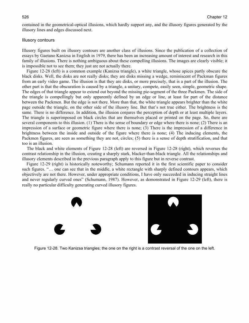
Chapter 12 526
contained in the geometrical-optical illusions, which hardly support any, and the illusory figures generated by the illusory lines and edges discussed next. Illusory contours Illusory figures built on illusory contours are another class of illusions. Since the publication of a collection of essays by Gaetano Kanizsa in English in 1979, there has been an increasing amount of interest and research in this family of illusions. There is nothing ambiguous about these compelling illusions. The images are clearly visible; it is impossible not to see them; they just are not actually there. Figure 12-28 (left) is a common example (Kanizsa triangle), a white triangle, whose apices partly obscure the black disks. Well, the disks are not really disks; they are disks missing a wedge, reminiscent of Packman figures from an early video game. The illusion is that they are disks, or more precisely, that is a part of the illusion. The other part is that the obscuration is caused by a triangle, a unitary, compete, easily seen, simple, geometric shape. The edges of that triangle appear to extend out beyond the missing pie-segment of the three Packmen. The side of the triangle is compellingly but only apparently defined by an edge or line, at least for part of the distance between the Packmen. But the edge is not there. More than that, the white triangle appears brighter than the white page outside the triangle, on the other side of the illusory line. But that’s not true either. The brightness is the same. There is no difference. In addition, the illusion conjures the perception of depth or at least multiple layers. The triangle is superimposed on black circles that are themselves placed or printed on the page. So, there are several components to this illusion. (1) There is the sense of boundary or edge where there is none; (2) There is an impression of a surface or geometric figure where there is none; (3) There is the impression of a difference in brightness between the inside and outside of the figure where there is none; (4) The inducing elements, the Packmen figures, are seen as something they are not, circles; (5) there is a sense of depth stratification, and that too is an illusion. The black and white elements of Figure 12-28 (left) are reversed in Figure 12-28 (right), which reverses the contrast relationship in the illusion, creating a sharply stark, blacker-than-black triangle. All the relationships and illusory elements described in the previous paragraph apply to this figure but in reverse contrast. Figure 12-29 (right) is historically noteworthy; Schumann reported it in the first scientific paper to consider such figures. “… one can see that in the middle, a white rectangle with sharply defined contours appears, which objectively are not there. However, under appropriate conditions, I have only succeeded in inducing straight lines and never regularly curved ones” (Schumann, 1987). However, as demonstrated in Figure 12-29 (left), there is really no particular difficulty generating curved illusory figures.
Figure 12-28. Two Kanizsa triangles; the one on the right is a contrast reversal of the one on the left.

Visual Perceptual Conflicts and Illusions 527
Figure 12-29. (Left) Illusory figures built on curved illusory contours; (Right) The first of this class of illusory figures to be reported in the literature (Schumann, 1987).
There exists currently a large literature on this type of illusions, which includes a great deal of discussion concerning the necessary and sufficient conditions for these illusions and their underling causes. The issues raised are really quite complicated, far exceeding the scope of the present review; but there is one more point that needs to be made about them, particularly in the context of see-through HMDs and superimposed, transparent HUD displays. Can these illusory edges and the figures occur with HMDs, either intentionally as design elements, or accidentally, interacting in the see-through fashion, superimposing symbology on the scene? These illusory contours and figures are not far removed from perceptions involving transparency, as Figure 12-30 suggests. It may be suspected that they will be increasingly important as HMD technology develops.
Figure 12-30. The elements on the left can combine to produce the illusion of transparency (Kanizsa, 1979).
Impossible figures Impossible figures (objects) belong to a final class of static visual illusions to be discussed here and are distinct from those discussed above. These optical illusions, e.g., the Devil’s tuning fork (Figure 12-31, left) or the Freemish crate (Figure 12-31, right), are not so much a visual illusion as they are unambiguous, explicit depictions of physical impossibilities. They live in a middle ground between perception and logic, taxing both. Many of the figures and illustrations by Escher work on this principle. These may be better described as illusions of higher order cognition than of perception. This distinction is not to minimize their importance by any means. It may be that some episodes of spatial disorientation (SD) in aircraft are analogous to these cognitive illusions. One classification of SD distinguishes between instances when individuals recognize that they are disoriented from instances in which the SD goes unrecognized. When the individual recognizes the SD, the challenge is to reconcile two different and mutually exclusive visions of reality. The aviator struggles to figure out how to accomplish this. It is a cognitive problem; the two sources of information just do not fit together. This is very much the experience of fitting the Devil’s Tuning Fork into a single percept; it just doesn’t fit.
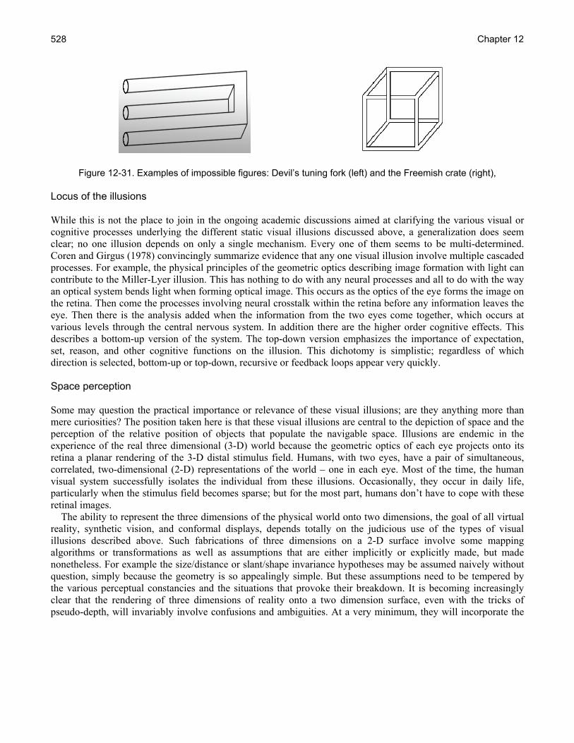
Chapter 12 528
Figure 12-31. Examples of impossible figures: Devil’s tuning fork (left) and the Freemish crate (right), Locus of the illusions While this is not the place to join in the ongoing academic discussions aimed at clarifying the various visual or cognitive processes underlying the different static visual illusions discussed above, a generalization does seem clear; no one illusion depends on only a single mechanism. Every one of them seems to be multi-determined. Coren and Girgus (1978) convincingly summarize evidence that any one visual illusion involve multiple cascaded processes. For example, the physical principles of the geometric optics describing image formation with light can contribute to the Miller-Lyer illusion. This has nothing to do with any neural processes and all to do with the way an optical system bends light when forming optical image. This occurs as the optics of the eye forms the image on the retina. Then come the processes involving neural crosstalk within the retina before any information leaves the eye. Then there is the analysis added when the information from the two eyes come together, which occurs at various levels through the central nervous system. In addition there are the higher order cognitive effects. This describes a bottom-up version of the system. The top-down version emphasizes the importance of expectation, set, reason, and other cognitive functions on the illusion. This dichotomy is simplistic; regardless of which direction is selected, bottom-up or top-down, recursive or feedback loops appear very quickly. Space perception Some may question the practical importance or relevance of these visual illusions; are they anything more than mere curiosities? The position taken here is that these visual illusions are central to the depiction of space and the perception of the relative position of objects that populate the navigable space. Illusions are endemic in the experience of the real three dimensional (3-D) world because the geometric optics of each eye projects onto its retina a planar rendering of the 3-D distal stimulus field. Humans, with two eyes, have a pair of simultaneous, correlated, two-dimensional (2-D) representations of the world – one in each eye. Most of the time, the human visual system successfully isolates the individual from these illusions. Occasionally, they occur in daily life, particularly when the stimulus field becomes sparse; but for the most part, humans don’t have to cope with these retinal images. The ability to represent the three dimensions of the physical world onto two dimensions, the goal of all virtual reality, synthetic vision, and conformal displays, depends totally on the judicious use of the types of visual illusions described above. Such fabrications of three dimensions on a 2-D surface involve some mapping algorithms or transformations as well as assumptions that are either implicitly or explicitly made, but made nonetheless. For example the size/distance or slant/shape invariance hypotheses may be assumed naively without question, simply because the geometry is so appealingly simple. But these assumptions need to be tempered by the various perceptual constancies and the situations that provoke their breakdown. It is becoming increasingly clear that the rendering of three dimensions of reality onto a two dimension surface, even with the tricks of pseudo-depth, will invariably involve confusions and ambiguities. At a very minimum, they will incorporate the
Visual Perceptual Conflicts and Illusions 529
confusions and ambiguities that are inherent in the real world. This is evidenced by the growing volume of human factors research on the relative strengths and weaknesses of various perspective or 3-D displays, some of which is discussed by St. John et al. (2001), as well as in Chapters 2, The Human-Machine Interface Challenge, and Chapter 10, Visual Perception and Cognitive Performance. One of the deepest conundrums of visual perception is mapping the dimensions of physical space into a spatial representation of visual spatial experience. The 3-D geometry of the visual world is transformed into the planar geometry of the retina. One of the themes of this discussion is that at any one moment the image on the retina of the distal visual stimulus field is highly confusing, ambiguous, and complicated. Our neural-visual machinery is designed to take apart and analyze that confusing, ambiguous, and complicated surface rendering. Separate, simultaneous systems tuned to specific aspects of the image perform these multiple simultaneous analyses, splaying the image apart in different regions of the brain. Color information processed in regions A, edge information processed in regions B, occulo-motor information in regions C, visual disparities in regions D, and so on, all at roughly the same time, and all these regions overlapping or sharing information to some extent. With such a complicated ensemble of cross-talking (leaky) parallel systems, each analyzing particular pieces of the visual puzzle, why should there be one mapping of physical into visual space? And, if there is more than one, how many are there? Are they all equally important? What is their relative importance to a specific task, be it perceptual or motor? And, how would these different mappings be accommodated to HMDs, either see-through or otherwise? Some vision researchers have explicitly argued that the visual system incorporates multiple simultaneous mappings of the space around us. For example, the earlier discussion of the horoptor described one approach to mapping equal perceptual distances based on fusional areas, the regions that produce single vision. Another approach is mapping regions of the visual field that have equal sensitivity to such specified stimulus parameters as luminance, color or motion. This technique, perimetry, is common to the eye clinic (Aulhorn and Harms, 1972). Yet another approach is to equalize or re-scale the visual field in terms of acuity (Anstis, 1974) or cortical magnification (Crowey and Rolls, 1974), size and distance judgments (Wagner, 2004), or any of a number of other specific visual functions (MacLeod and Willen, 1995). The number of different approaches to providing a visual representation of the physical is large. Mapping for one dimension may violate mappings in other dimensions, which could produce confusions and misjudgments along these dimensions. In a 2-D representation of 3-D space, distance perception of necessity is confused and confusing. Objects get smaller as they get further away but there is a catch, perspective. The effect is not obvious, even textbooks on perception, in illustrations and discussions of depth perception have gotten it wrong (Gillam, 1981). Smallman, Manes and Cowen (2003) state, “It is not widely appreciated, even among vision researchers, that projected width across a scene (X) and projected depth into a scene (Y) taper differently with distance in to the scene. Projected width is inversely proportional to distance. Projected depth (Y) on the other hand is inversely proportional to the square of distance because of foreshortening.” These different relationships certainly complicate the perception and understanding of size and distance information represented in graphical displays. They also complicate the perception and understanding of size and distance information represented in the real world; these are not noticed, because, perception is itself an illusion. Creating displays that mimic or emulate the real world may build these illusions into the display and produce much the same effects. Dynamic Illusions As with static visual illusions, dynamic illusions are constantly present. The success of visual information display technologies, including head-mounted and virtual ones, will be better served by understanding that visual perceptions inevitably involve some form of illusions and raises challenges for defining the criteria and desiderata for such displays. A survey of U.S. Army AH-64 Apache helicopter accidents, reported for the period from 1985 to 2002, concluded that dynamic illusions are particularly important when using the Apache’s HMD, the Integrated Helmet and Display Sighting System (IHADSS) (Rash et al., 2003). Of the 228 reported accidents,

Chapter 12 530
approximately 93 (41%) involved the HMD in some way, and for 21 of these, the HMD and pilotage night vision sensor system played a role in the accident sequence itself. Furthermore, the most frequent causal factor in all of the accidents studied was the presence of dynamic (motion-based) illusions, which were identified as disorientation (14%), illusory drift (24%), faulty closure judgment (10%), and undetected drift (24%). The relatively important role of dynamic illusions reported in these accidents suggests that the illusions associated with motion perception warrant special attention. The survey reported that the second most frequent cause was degraded vision (i.e., reduced resolution and contrast). This is consistent with the arguments made in the earlier discussion of static illusions, i.e., the more sparse or degraded the visual stimulus field, the more pronounced are the illusory percepts. Nevertheless, the absence of an accident does not mean that the pilot had no visual illusions, since pilots routinely and successfully control aircraft in the presence of multiple visual illusions. What is motion perception? Understanding dynamic illusions requires some understanding of motion perception14 and, of course, at least some of the more common illusions associated with motion. An interesting question is why the perception of motion poses any special perceptual problems. When an object moves in the visual field, such as an automobile passing in front of the eye, the image of the object flows over the retina. It might seem obvious that the movement of the car’s image over the retina should produce the perception of the car moving through a static environment. Or, consider a situation in which an individual tracks a passing car with their gaze. In this case, eye movement keeps the image of the car relatively stable on the retina, but the image of the rest of the world around the car is moving. The image of the static environment moves over the retina as the retina moves to keep the image of the car relatively stable. In both cases, there is still differential motion between the images of the moving car and the static environment. Since humans have the perception of motion when an image of an object courses over the retina, it may not only seem a strange but even an unjustified violation of parsimony to ague that there may exist a special system responsible for motion perception. Consider the passenger in the car, such that the image of the world through which the passenger is passing is visible around him through the windows. As the passenger looks through the windshield, vehicular structures, such as its hood, dashboard, the spots on the transparent glass of the windshield, are all approximately stationary relative to him and the moving world outside. As the car travels, the visual system effortlessly disambiguates the complex patterns of differential motions on the retina. But, as impressive as this accomplishment is, since all these motions are associated with streaming objects that have specific and constant identities, one is tempted still to not be totally convinced that it is necessary to postulate a special system responsible for the perception of motion. Let’s say that the driver stops the car at a red light, and the passenger turns his head to look at the driver. Another car pulls to a stop the adjacent lane, on the diver’s side, filling the passenger’s view of the world behind the diver. As the passenger views the driver, he suddenly perceives the car he is in begin to roll slowly backwards and in a reflective reaction turns quickly to look out the back window to check that the car he is in is not going to roll backward into a car to the rear. However, he quickly ascertain see that his car is not moving at all, and the driver still has a foot on the brake. What really happened is that the light has turned green and the car, which had had seen as stationary behind the driver, in fact had begun gradually to pull forward while his car remained stationary. As the passenger was attending to the driver, some part of the visual system registered the motion of the car visible behind him. That situation produced a strong, compelling sense of motion, even though the passenger and the car he is in were not moving.15 Let’s examine another situation. An individual arrive at a movie house and spend the next two hours watching a film. Several hundred million dollars were spent and thousands of people worked on the creation of this extended, two-hour illusion. There were no real actors moving in front of the moviegoer, as actually occurs in a stage-
14 See Chapter 10, Visual Perception and Cognitive Performance, for an expanded discussion on motion perception. 15 This sensation of movement of the self in space produced purely by visual stimulation is called vection.

Visual Perceptual Conflicts and Illusions 531
theater. Rather, he just spent two hours watching a sequence of two-dimensional distributions of variously-colored light. The whole experience is conjured. At the end of the show the credits appear to “roll” by. They are read as if they “scroll upward.” 16 The movie often ends with a final stationary image, e.g., production company logo or a final message. For a moment, it may be perceived as a curious fact that this stationary image seems to move in the opposite (“downward”) direction. Motion perception and Gestalt psychology Boring (1942) noted that Perkinje’s studies of motion sickness and vertigo from 1820 through 1827 may mark the beginning of the scientific study of motion perception and illusions. By 1831, the physicist Michael Faraday had described stroboscopic motion, and the word stroboscope had come into use by 1833. Interestingly, many of the devices and effects used to generate such motion perceptions were created for parlor amusement and entertainment. In other words, entertainment drove much of these 19th century technological innovations in much the same way that entertainment is driving display technologies today. During this same period, Addams (1834) published, “An Account of a Peculiar Optical Phaenomenon Seen after Having Looked at a Moving Body.” He was reporting a motion aftereffect sometimes called the waterfall illusion. After watching the water coursing downward in a waterfall for a few minutes, such nearby stationary objects as rocks, grass, trees, etc., appear to move in the opposite direction. This illusion is what occurs with the previously described credits at the end of the film. Over the years, many researchers (including Helmholtz [1909]) have argued incorrectly that such motion aftereffects (MAEs) were due to eye movements. Others, including Ernst Mach, have argued that eye movements cannot account for MAEs. For example, if one eye looks at a pair of spirals simultaneously rotating in opposite directions, the eye will have simultaneous MAEs in different circular directions; this cannot be accounted for by eye movements. Mach and others argued that MAEs must reflect the operation of some kind of neural-retinal mechanism(s). Certainly, by the 1870s some vision scientists had begun to argue that motion per se was a basic visual, if not retinal, process. Exner (1875) studied the perception of two electric sparks separated in time and distance. He found that when the pair of sparks was flashed with a delay of 45 ms or longer, the order of illumination could be detected. When the sparks were moved closer together, their sequential illumination provoked a perception of motion that was seen even with a delay as brief as 14 ms. In other words, motion was seen even when the time interval between the two sparks was too brief to determine the order in which they were illuminated. The argument developed that motion does not depend upon an object changing its location over time. Exner (1875 ) concluded that motion was a sensation rather than a perception.17 This argument of motion has special importance historically; it is the very root of Gestalt psychology. In Wertheimer’s 1912 paper on his studies of apparent motion, specifically on something called phi motion, he extended the arguments that Mach and Exner made almost thirty years earlier. He emphasized that such motion perception does not depend on an object or its identity, and that motion perception is not a derived reality but it is a basic phenomenon that reflects cortical processes. He further argued that the veracity of the perception of motion is not dependent on the real motion of a real object but depends on what happens in the brain. These arguments quickly led to a number of studies of differing types of motion, as the Gestaltists differentiated a number of motion types. Table 12-1 is based on Boring’s summary and lists a number of these motions and their characteristics.
16 Of course, the credits aren’t really scrolling, as that too is an illusion resulting from the rapid sequential presentation of static images, just like the rest of the film. 17 Although the distinction between a sensation and perception is important historically but less clear today, it is still embodied in the dichotomy between top-down and bottom-up processing. Sensations reflect the atomistic, basic, raw function of a sensory system; while perception is the resultant organization of the basic building blocks into a neural event that is more than the sum of the sensations. A percept is the organization of the set of sensations. But, these distinctions are all just words that beg careful definitions.
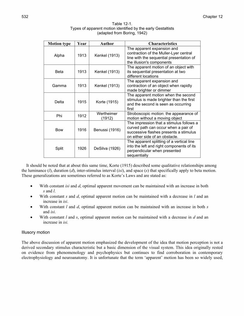
Chapter 12 532
Table 12-1. Types of apparent motion identified by the early Gestaltists
(adapted from Boring, 1942)
Motion type Year Author Characteristics
Alpha 1913 Kenkel (1913)
The apparent expansion and contraction of the Muller-Lyer central line with the sequential presentation of the illusion's components
Beta 1913 Kenkel (1913) The apparent motion of an object with its sequential presentation at two different locations
Gamma 1913 Kenkel (1913) The apparent expansion and contraction of an object when rapidly made brighter or dimmer
Delta 1915 Korte (1915)
The apparent motion when the second stimulus is made brighter than the first and the second is seen as occurring first
Phi 1912 Wertheimer (1912)
Stroboscopic motion: the appearance of motion without a moving object
Bow 1916 Benussi (1916)
The impression that a stimulus follows a curved path can occur when a pair of successive flashes presents a stimulus on either side of an obstacle.
Split 1926 DeSilva (1926)
The apparent splitting of a vertical line into the left and right components of its perpendicular when presented sequentially
It should be noted that at about this same time, Korte (1915) described some qualitative relationships among the luminance (l), duration (d), inter-stimulus interval (isi), and space (s) that specifically apply to beta motion. These generalizations are sometimes referred to as Korte’s Laws and are stated as:
• With constant isi and d, optimal apparent movement can be maintained with an increase in both
s and l. • With constant s and d, optimal apparent motion can be maintained with a decrease in l and an
increase in isi. • With constant l and d, optimal apparent motion can be maintained with an increase in both s
and isi. • With constant l and s, optimal apparent motion can be maintained with a decrease in d and an
increase in isi.
Illusory motion The above discussion of apparent motion emphasized the development of the idea that motion perception is not a derived secondary stimulus characteristic but a basic dimension of the visual system. This idea originally rested on evidence from phenomenology and psychophysics but continues to find corroboration in contemporary electrophysiology and neuroanatomy. It is unfortunate that the term ‘apparent’ motion has been so widely used,
Visual Perceptual Conflicts and Illusions 533
because it is imprecise. All perceived motion, whether real or illusory, is apparent. Illusory motion would have been a more accurate term, referring to a situation in which motion is seen but is not actually present Regardless of the word employed, apparent or illusory, the perception of motion and the processing of motion information now are known to depend upon the function of basic processes in the visual system. Furthermore, the study of the dependence of the percept on stimulus conditions reveals how these systems work. The emphasis on apparent motion begs the further question of whether there are differences between illusory and real motion. This broad question probably only really makes sense in the context of specific cases, since there are so many types of such motion percepts. The present discussion will address five different types of illusory motion: (1) stroboscopic motion, (2) the autokinetic effect, (3) induced motion, (4) the Pulfrich phenomenon, and (5) motion aftereffects. Each of these types illustrates the operation of different processes involved with motion perception. Together, they illustrate the range of phenomena that can provoke illusory motion. Furthermore, not only do these five phenomena occur in increasingly complex stimulus fields; but each occurs in the real world and affects visually-dependent performance, at least in the context of aviation in the real world. Stroboscopic motion
As Wertheimer and his colleagues were studying illusory motion and building their arguments about Gestalt psychology, more pragmatically-oriented individuals were developing techniques to use the same phenomena to make moving pictures. The rapid sequential presentation of stationary images produces stroboscopic motion, also called the phi phenomenon (or beta motion).18 It is extraordinary how endemic this type of illusory stroboscopic motion is in modern society, whereas it was a curiosity in the mid-19th century. Possibly the simplest example of the basic experimental paradigm may involve a pair of easily observed, identical, short flashes of lights, F1 and F2, presented one right after another, each with a relatively short, well-defined, constant duration (e.g., 250 ms). The interval between the offset of F1 and the onset of F2 is typically referred to as the inter-stimulus interval (ISI) and in this simple example may be set equal to the flash duration (i.e., 250 ms). When F1 and F2 are presented at the same location but separated in time by the 250 ms ISI, the percept is relatively simple: A light comes on, goes off, comes on, goes off, etc., all in the same location. Since F1 and F2 are identical and in the same location, the observer actually perceives only one flashing light. The situation becomes more interesting when F1 and F2 are spatially separated (e.g., a few degrees) (Figure 12-32), so that one is to the side of the other, e.g., F2 is to the right of F1. With the ISI still at 250 ms, the percept is unambiguously that of two different lights presented in succession at two different locations. When the ISI is very short (e.g., 30 ms), F1 and F2 appear as two simultaneous flashes next to each other; the ISI is too short for the visual system to detect. Clearly, the percept depends on the duration of the ISI. The interesting issue is how the percept changes as a function of the ISI. Specifically, in the ISI range between the 30 ms and 250 ms, there is a range of ISIs that produces a very strong perception of motion between F1 and F2. It is as though F1 jumps clearly and unambiguously to F2. F1 and F2 are not seen as two separate flashes, either simultaneously or successively presented; rather, they are seen as a single flash that moves from one place to another. The ISI that gives the strongest perception of such motion depends upon the spatial distance between the flashes, their luminance, duration, and size, exactly as described by Korte’s laws. For example, in the situation described here, with F1 and F2 separated by a few degrees, an ISI of about 60 ms would a produce strong definitive, unambiguous perception of motion.
18 The phi phenomenon is a perceptual illusion described by Max Wertheimer by which a perception of motion is produced by a succession of still images.
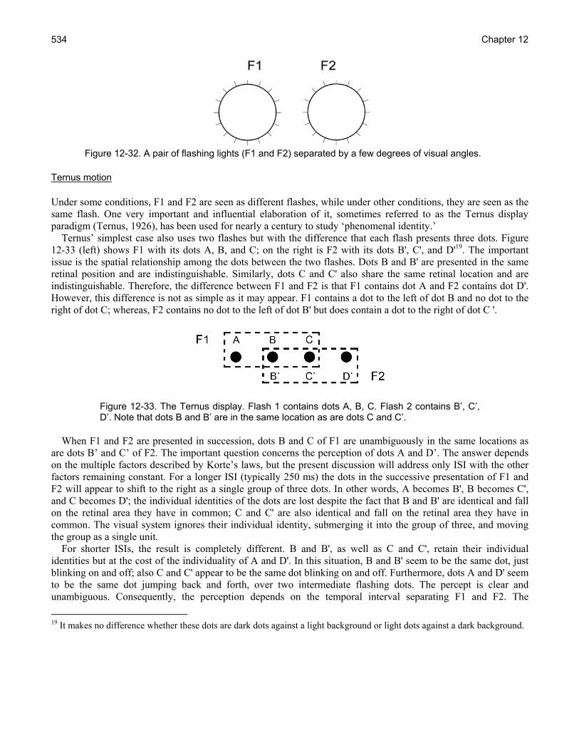
Chapter 12 534
Figure 12-32. A pair of flashing lights (F1 and F2) separated by a few degrees of visual angles. Ternus motion Under some conditions, F1 and F2 are seen as different flashes, while under other conditions, they are seen as the same flash. One very important and influential elaboration of it, sometimes referred to as the Ternus display paradigm (Ternus, 1926), has been used for nearly a century to study ‘phenomenal identity.’ Ternus’ simplest case also uses two flashes but with the difference that each flash presents three dots. Figure 12-33 (left) shows F1 with its dots A, B, and C; on the right is F2 with its dots B', C', and D'19. The important issue is the spatial relationship among the dots between the two flashes. Dots B and B' are presented in the same retinal position and are indistinguishable. Similarly, dots C and C' also share the same retinal location and are indistinguishable. Therefore, the difference between F1 and F2 is that F1 contains dot A and F2 contains dot D'. However, this difference is not as simple as it may appear. F1 contains a dot to the left of dot B and no dot to the right of dot C; whereas, F2 contains no dot to the left of dot B' but does contain a dot to the right of dot C '.
Figure 12-33. The Ternus display. Flash 1 contains dots A, B, C. Flash 2 contains B’, C’, D’. Note that dots B and B’ are in the same location as are dots C and C’.
When F1 and F2 are presented in succession, dots B and C of F1 are unambiguously in the same locations as are dots B’ and C’ of F2. The important question concerns the perception of dots A and D’. The answer depends on the multiple factors described by Korte’s laws, but the present discussion will address only ISI with the other factors remaining constant. For a longer ISI (typically 250 ms) the dots in the successive presentation of F1 and F2 will appear to shift to the right as a single group of three dots. In other words, A becomes B', B becomes C', and C becomes D'; the individual identities of the dots are lost despite the fact that B and B' are identical and fall on the retinal area they have in common; C and C' are also identical and fall on the retinal area they have in common. The visual system ignores their individual identity, submerging it into the group of three, and moving the group as a single unit. For shorter ISIs, the result is completely different. B and B', as well as C and C', retain their individual identities but at the cost of the individuality of A and D'. In this situation, B and B' seem to be the same dot, just blinking on and off; also C and C' appear to be the same dot blinking on and off. Furthermore, dots A and D' seem to be the same dot jumping back and forth, over two intermediate flashing dots. The percept is clear and unambiguous. Consequently, the perception depends on the temporal interval separating F1 and F2. The
19 It makes no difference whether these dots are dark dots against a light background or light dots against a dark background.
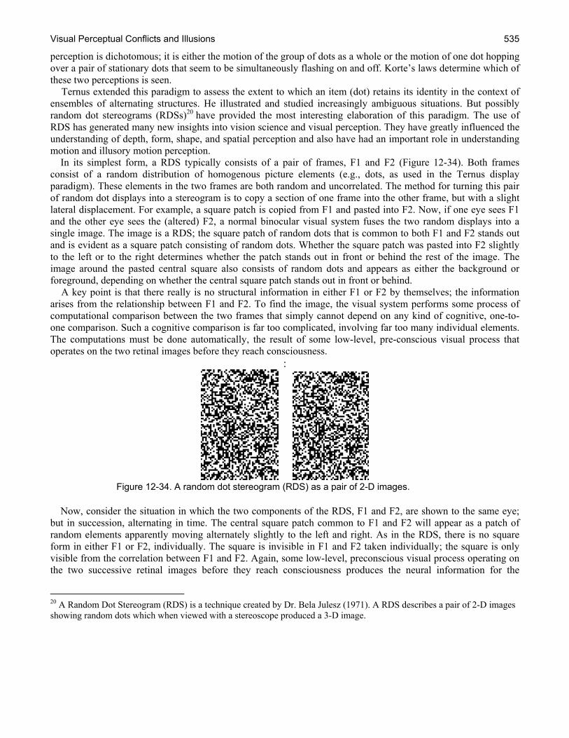
Visual Perceptual Conflicts and Illusions 535
perception is dichotomous; it is either the motion of the group of dots as a whole or the motion of one dot hopping over a pair of stationary dots that seem to be simultaneously flashing on and off. Korte’s laws determine which of these two perceptions is seen. Ternus extended this paradigm to assess the extent to which an item (dot) retains its identity in the context of ensembles of alternating structures. He illustrated and studied increasingly ambiguous situations. But possibly random dot stereograms (RDSs)20 have provided the most interesting elaboration of this paradigm. The use of RDS has generated many new insights into vision science and visual perception. They have greatly influenced the understanding of depth, form, shape, and spatial perception and also have had an important role in understanding motion and illusory motion perception. In its simplest form, a RDS typically consists of a pair of frames, F1 and F2 (Figure 12-34). Both frames consist of a random distribution of homogenous picture elements (e.g., dots, as used in the Ternus display paradigm). These elements in the two frames are both random and uncorrelated. The method for turning this pair of random dot displays into a stereogram is to copy a section of one frame into the other frame, but with a slight lateral displacement. For example, a square patch is copied from F1 and pasted into F2. Now, if one eye sees F1 and the other eye sees the (altered) F2, a normal binocular visual system fuses the two random displays into a single image. The image is a RDS; the square patch of random dots that is common to both F1 and F2 stands out and is evident as a square patch consisting of random dots. Whether the square patch was pasted into F2 slightly to the left or to the right determines whether the patch stands out in front or behind the rest of the image. The image around the pasted central square also consists of random dots and appears as either the background or foreground, depending on whether the central square patch stands out in front or behind. A key point is that there really is no structural information in either F1 or F2 by themselves; the information arises from the relationship between F1 and F2. To find the image, the visual system performs some process of computational comparison between the two frames that simply cannot depend on any kind of cognitive, one-to-one comparison. Such a cognitive comparison is far too complicated, involving far too many individual elements. The computations must be done automatically, the result of some low-level, pre-conscious visual process that operates on the two retinal images before they reach consciousness.
:
Figure 12-34. A random dot stereogram (RDS) as a pair of 2-D images.
Now, consider the situation in which the two components of the RDS, F1 and F2, are shown to the same eye; but in succession, alternating in time. The central square patch common to F1 and F2 will appear as a patch of random elements apparently moving alternately slightly to the left and right. As in the RDS, there is no square form in either F1 or F2, individually. The square is invisible in F1 and F2 taken individually; the square is only visible from the correlation between F1 and F2. Again, some low-level, preconscious visual process operating on the two successive retinal images before they reach consciousness produces the neural information for the
20 A Random Dot Stereogram (RDS) is a technique created by Dr. Bela Julesz (1971). A RDS describes a pair of 2-D images showing random dots which when viewed with a stereoscope produced a 3-D image.
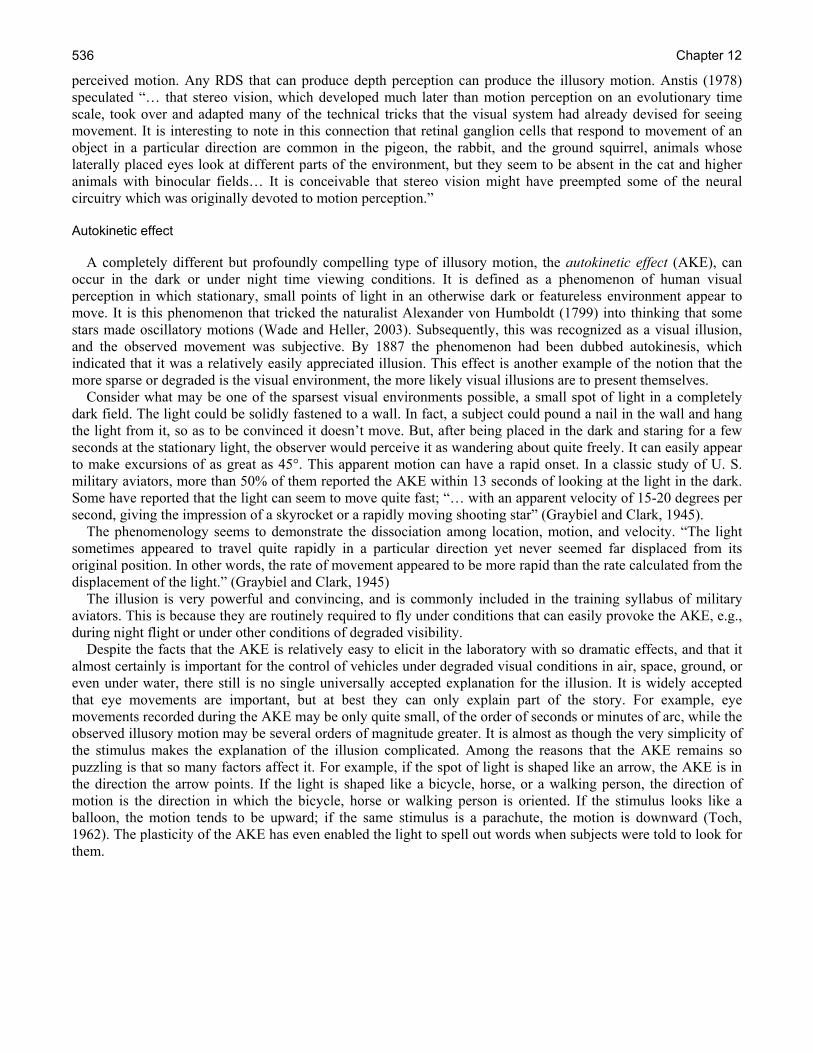
Chapter 12 536
perceived motion. Any RDS that can produce depth perception can produce the illusory motion. Anstis (1978) speculated “… that stereo vision, which developed much later than motion perception on an evolutionary time scale, took over and adapted many of the technical tricks that the visual system had already devised for seeing movement. It is interesting to note in this connection that retinal ganglion cells that respond to movement of an object in a particular direction are common in the pigeon, the rabbit, and the ground squirrel, animals whose laterally placed eyes look at different parts of the environment, but they seem to be absent in the cat and higher animals with binocular fields… It is conceivable that stereo vision might have preempted some of the neural circuitry which was originally devoted to motion perception.” Autokinetic effect A completely different but profoundly compelling type of illusory motion, the autokinetic effect (AKE), can occur in the dark or under night time viewing conditions. It is defined as a phenomenon of human visual perception in which stationary, small points of light in an otherwise dark or featureless environment appear to move. It is this phenomenon that tricked the naturalist Alexander von Humboldt (1799) into thinking that some stars made oscillatory motions (Wade and Heller, 2003). Subsequently, this was recognized as a visual illusion, and the observed movement was subjective. By 1887 the phenomenon had been dubbed autokinesis, which indicated that it was a relatively easily appreciated illusion. This effect is another example of the notion that the more sparse or degraded is the visual environment, the more likely visual illusions are to present themselves. Consider what may be one of the sparsest visual environments possible, a small spot of light in a completely dark field. The light could be solidly fastened to a wall. In fact, a subject could pound a nail in the wall and hang the light from it, so as to be convinced it doesn’t move. But, after being placed in the dark and staring for a few seconds at the stationary light, the observer would perceive it as wandering about quite freely. It can easily appear to make excursions of as great as 45°. This apparent motion can have a rapid onset. In a classic study of U. S. military aviators, more than 50% of them reported the AKE within 13 seconds of looking at the light in the dark. Some have reported that the light can seem to move quite fast; “… with an apparent velocity of 15-20 degrees per second, giving the impression of a skyrocket or a rapidly moving shooting star” (Graybiel and Clark, 1945). The phenomenology seems to demonstrate the dissociation among location, motion, and velocity. “The light sometimes appeared to travel quite rapidly in a particular direction yet never seemed far displaced from its original position. In other words, the rate of movement appeared to be more rapid than the rate calculated from the displacement of the light.” (Graybiel and Clark, 1945) The illusion is very powerful and convincing, and is commonly included in the training syllabus of military aviators. This is because they are routinely required to fly under conditions that can easily provoke the AKE, e.g., during night flight or under other conditions of degraded visibility. Despite the facts that the AKE is relatively easy to elicit in the laboratory with so dramatic effects, and that it almost certainly is important for the control of vehicles under degraded visual conditions in air, space, ground, or even under water, there still is no single universally accepted explanation for the illusion. It is widely accepted that eye movements are important, but at best they can only explain part of the story. For example, eye movements recorded during the AKE may be only quite small, of the order of seconds or minutes of arc, while the observed illusory motion may be several orders of magnitude greater. It is almost as though the very simplicity of the stimulus makes the explanation of the illusion complicated. Among the reasons that the AKE remains so puzzling is that so many factors affect it. For example, if the spot of light is shaped like an arrow, the AKE is in the direction the arrow points. If the light is shaped like a bicycle, horse, or a walking person, the direction of motion is the direction in which the bicycle, horse or walking person is oriented. If the stimulus looks like a balloon, the motion tends to be upward; if the same stimulus is a parachute, the motion is downward (Toch, 1962). The plasticity of the AKE has even enabled the light to spell out words when subjects were told to look for them.

Visual Perceptual Conflicts and Illusions 537
The most widely accepted explanation of the AKE is some version of that proposed by Gregory and Zangwill (1963). This class of explanations calls on the notion of a cortico-cortical feed-forward signal (efferent copy).21 As Helmholtz first pointed out, physically moving the eyeball causes the entire image on the retina to appear to move. On the other hand, if the eye of an awake person is immobilized so that it cannot move, the person reports that the world seems to jump when attempting or willing the immobilized eye to move. These observations have been taken as evidence that when the nervous system sends an efferent signal to the extraocular muscles to move the eye, the sensory/perceptual systems receive a copy of that efferent signal so that the interpretation of the retinal image includes the anticipated voluntary motion of the eye. The results of the anticipated ocular motion are calculated into the percept. The perception of movement when the eye is passively moved is attributed to the absence of the efferent copy, whereas the perception of movement when the restrained eye attempts to move is attributed to the present of the efferent copy. Consistent with this idea is the demonstration that if the conjunctival sack around the eye is anesthetized, the eye can be mechanically moved in the dark without any perception of where the eye is looking. Apparently, there is no information coming from the eye about its orientation or position other than what is provided by the images on the retina themselves. It is as though the eye has no proprioception other than the visual image, so the efferent copy serves that purpose. Gregory and Zangwill (1963) proposed that, in a degraded sparse visual environment with few stimuli, the AKE is due to spontaneous fluctuations in this efferent copy system. The AKE is a clear example of the complexity of the illusions that occur in a sparse environment. The environment is sparse and the illusions are compelling, but the explanation is complex. Again, the AKE is not just a laboratory curiosity but something that should be anticipated in the real world, though admittedly under some extreme conditions. Under normal daytime viewing conditions, the AKE rarely occurs. The relative position of an object with respect to other objects in the visual field provides information sufficient to determine whether the object is moving or not. Some have argued that the perception that an object is moving depends on the perception of stability (Dichgans and Brandt, 1978). That is, the perception of motion includes the perception of non-motion. With fewer visual elements there is decreased information about relative non-motion. With fewer elements in the visual field there is less information available concerning the relative distances among the stimulus elements. These relative distances among the visual elements is the very information missing during the AKE, information that would allow the calibration of the null point of the efferent copy.
Induced motion Induced motion is the incorrectly perceived velocity/direction of the motion of an object caused by background motion (Duncker, 1929). Levine and Shefner (1991) give the following example: ``...consider a cloudy night sky with the moon ducking in and out of the drifting clouds. The moon is actually stationary relative to the clouds, but because the clouds take up so much more room in the visual field than the moon, they appear to be stationary while the moon seems to move in the opposite direction from them.'' Unlike the AKE, there really is motion in this situation; the real motion of the cloud near the stationary moon, but the motion was misinterpreted. Simply because there is some structure in the visual field does not necessarily mean that the percept will be veridical. Movement was attributed to the wrong element. This perceptual misunderstanding emphasized the notion that all motion is relative. Without a reference there is no motion.22 The sensitivity to the motion of a single dot in an otherwise empty visual field is very poor when compared to the sensitivity to the motion of the same dot when another dot is near by. But with two dots; which one moved?
21 Efferent copy theory was developed by von Holst and Mittelsteadt (1950) to account for head adjustments made by flies in response to moving stimuli. The efferent copy mechanism is invoked to explain such phenomena as how a person perceives a motionless world when he/she shifts his/her eyes but perceives a moving world when pushed by someone else (Frijda, 2006). 22 With respect to the AKE, the stimulus element is seen to be in motion with respect to one’s self.
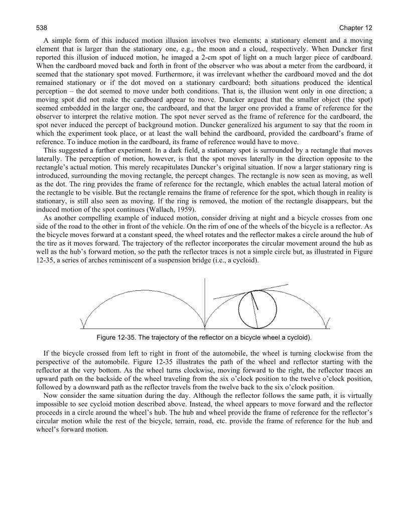
Chapter 12 538
A simple form of this induced motion illusion involves two elements; a stationary element and a moving element that is larger than the stationary one, e.g., the moon and a cloud, respectively. When Duncker first reported this illusion of induced motion, he imaged a 2-cm spot of light on a much larger piece of cardboard. When the cardboard moved back and forth in front of the observer who was about a meter from the cardboard, it seemed that the stationary spot moved. Furthermore, it was irrelevant whether the cardboard moved and the dot remained stationary or if the dot moved on a stationary cardboard; both situations produced the identical perception – the dot seemed to move under both conditions. That is, the illusion went only in one direction; a moving spot did not make the cardboard appear to move. Duncker argued that the smaller object (the spot) seemed embedded in the larger one, the cardboard, and that the larger one provided a frame of reference for the observer to interpret the relative motion. The spot never served as the frame of reference for the cardboard, the spot never induced the percept of background motion. Duncker generalized his argument to say that the room in which the experiment took place, or at least the wall behind the cardboard, provided the cardboard’s frame of reference. To induce motion in the cardboard, its frame of reference would have to move. This suggested a further experiment. In a dark field, a stationary spot is surrounded by a rectangle that moves laterally. The perception of motion, however, is that the spot moves laterally in the direction opposite to the rectangle’s actual motion. This merely recapitulates Duncker’s original situation. If now a larger stationary ring is introduced, surrounding the moving rectangle, the percept changes. The rectangle is now seen as moving, as well as the dot. The ring provides the frame of reference for the rectangle, which enables the actual lateral motion of the rectangle to be visible. But the rectangle remains the frame of reference for the spot, which though in reality is stationary, is still also seen as moving. If the ring is removed, the motion of the rectangle disappears, but the induced motion of the spot continues (Wallach, 1959). As another compelling example of induced motion, consider driving at night and a bicycle crosses from one side of the road to the other in front of the vehicle. On the rim of one of the wheels of the bicycle is a reflector. As the bicycle moves forward at a constant speed, the wheel rotates and the reflector makes a circle around the hub of the tire as it moves forward. The trajectory of the reflector incorporates the circular movement around the hub as well as the hub’s forward motion, so the path the reflector traces is not a simple circle but, as illustrated in Figure 12-35, a series of arches reminiscent of a suspension bridge (i.e., a cycloid).
Figure 12-35. The trajectory of the reflector on a bicycle wheel a cycloid).
If the bicycle crossed from left to right in front of the automobile, the wheel is turning clockwise from the perspective of the automobile. Figure 12-35 illustrates the path of the wheel and reflector starting with the reflector at the very bottom. As the wheel turns clockwise, moving forward to the right, the reflector traces an upward path on the backside of the wheel traveling from the six o’clock position to the twelve o’clock position, followed by a downward path as the reflector travels from the twelve back to the six o’clock position. Now consider the same situation during the day. Although the reflector follows the same path, it is virtually impossible to see cycloid motion described above. Instead, the wheel appears to move forward and the reflector proceeds in a circle around the wheel’s hub. The hub and wheel provide the frame of reference for the reflector’s circular motion while the rest of the bicycle, terrain, road, etc. provide the frame of reference for the hub and wheel’s forward motion.
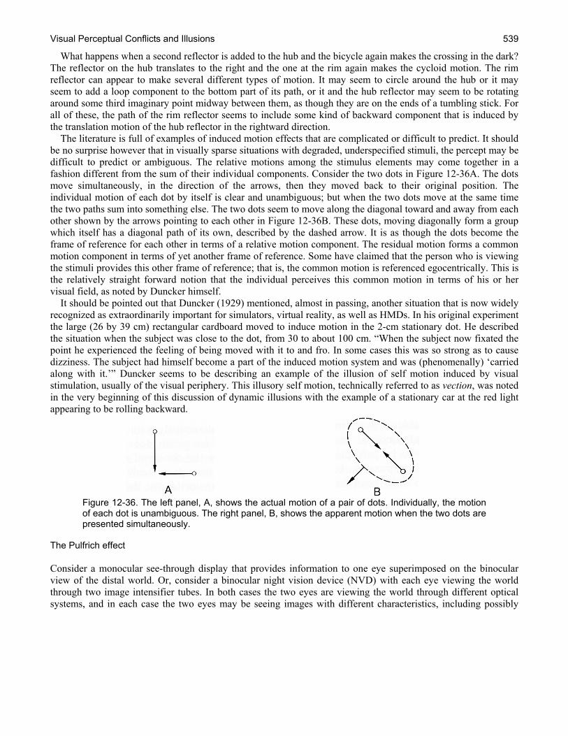
Visual Perceptual Conflicts and Illusions 539
What happens when a second reflector is added to the hub and the bicycle again makes the crossing in the dark? The reflector on the hub translates to the right and the one at the rim again makes the cycloid motion. The rim reflector can appear to make several different types of motion. It may seem to circle around the hub or it may seem to add a loop component to the bottom part of its path, or it and the hub reflector may seem to be rotating around some third imaginary point midway between them, as though they are on the ends of a tumbling stick. For all of these, the path of the rim reflector seems to include some kind of backward component that is induced by the translation motion of the hub reflector in the rightward direction. The literature is full of examples of induced motion effects that are complicated or difficult to predict. It should be no surprise however that in visually sparse situations with degraded, underspecified stimuli, the percept may be difficult to predict or ambiguous. The relative motions among the stimulus elements may come together in a fashion different from the sum of their individual components. Consider the two dots in Figure 12-36A. The dots move simultaneously, in the direction of the arrows, then they moved back to their original position. The individual motion of each dot by itself is clear and unambiguous; but when the two dots move at the same time the two paths sum into something else. The two dots seem to move along the diagonal toward and away from each other shown by the arrows pointing to each other in Figure 12-36B. These dots, moving diagonally form a group which itself has a diagonal path of its own, described by the dashed arrow. It is as though the dots become the frame of reference for each other in terms of a relative motion component. The residual motion forms a common motion component in terms of yet another frame of reference. Some have claimed that the person who is viewing the stimuli provides this other frame of reference; that is, the common motion is referenced egocentrically. This is the relatively straight forward notion that the individual perceives this common motion in terms of his or her visual field, as noted by Duncker himself. It should be pointed out that Duncker (1929) mentioned, almost in passing, another situation that is now widely recognized as extraordinarily important for simulators, virtual reality, as well as HMDs. In his original experiment the large (26 by 39 cm) rectangular cardboard moved to induce motion in the 2-cm stationary dot. He described the situation when the subject was close to the dot, from 30 to about 100 cm. “When the subject now fixated the point he experienced the feeling of being moved with it to and fro. In some cases this was so strong as to cause dizziness. The subject had himself become a part of the induced motion system and was (phenomenally) ‘carried along with it.’” Duncker seems to be describing an example of the illusion of self motion induced by visual stimulation, usually of the visual periphery. This illusory self motion, technically referred to as vection, was noted in the very beginning of this discussion of dynamic illusions with the example of a stationary car at the red light appearing to be rolling backward.
Figure 12-36. The left panel, A, shows the actual motion of a pair of dots. Individually, the motion of each dot is unambiguous. The right panel, B, shows the apparent motion when the two dots are presented simultaneously.
The Pulfrich effect Consider a monocular see-through display that provides information to one eye superimposed on the binocular view of the distal world. Or, consider a binocular night vision device (NVD) with each eye viewing the world through two image intensifier tubes. In both cases the two eyes are viewing the world through different optical systems, and in each case the two eyes may be seeing images with different characteristics, including possibly
Chapter 12 540
different brightnesses. The monocular display could be imposing a filter that reduces the amount of light to one eye;23 or the brightness of the two NVG tubes may be mismatched. Such luminance differences between the two eyes are known to affect the apparent depth of moving images. This dynamic illusion, called the Pulfrich effect, is important for optical systems designed to provide separate images to each eye. It also reveals important aspects of how the visual system works, aspects that are essentially unrelated to the kinds of illusions discussed so far. The Pulfrich effect has been defined as “the apparently ellipsoid or circular excursion of a pendulum actually swinging in a plane perpendicular to the direction of view when a light-absorbing filter is placed in front of one eye” (Cline, Hofstetter and Griffin, 1980). It is easy to demonstrate the Pulfrich phenomenon; a common classroom demonstration uses a pendulum and a filter of some sort. The filter does not have to be at all precise; the lens of a generic sunglass is sufficient. The pendulum swings back and forth in a left right direction in front of an observer who is watching the swinging motion with both eyes. An observer with normal binocular vision under normal viewing conditions sees the pendulum swinging back and forth in the frontal plane. Now the individual puts the filter in front of one eye, say the right eye, so that the right eye is still seeing the same image as the left eye, only dimmer because of the optical density of the filter. The pendulum is still seen with both eyes, but no longer seems to be swinging back and forth in the frontal plane. Instead, the pendulum seems to be swinging out of the plane in an arc. Specifically, with the filter in front of the right eye, as the pendulum moves toward the left, the path seems to bow away from the observer and as the pendulum swings back toward the right, it seems to bow toward the observer. In other words, its path seems to have a counter clockwise component to it when seen from above. This effect is more powerfully seen against a rich contoured background, which is one of the differences between this effect and the other dynamic illusions discussed earlier. Since it does occur in a rich environment, good visibility is no guarantee against its occurrence. If anything, good visibility makes the illusion stronger. The most widely accepted explanation of this phenomenon rests on the basic idea that nerve conduction is not instantaneous. Rather, it takes a finite amount of time for information to travel through the nervous system and that the speed of the conduction depends upon the stimulus luminance. Moreover, somewhere in the visual system the information from the two eyes must come together so that the information for the two eyes can be compared. This is the fundamental basis of stereoscoptic vision which provides the ability to see depth. This aspect of vision depends on a comparison of the neural information arriving from the two eyes. Under normal conditions, the information arrives at approximately the same time. But the comparison of the neural information from the two eyes will be disrupted if the timing of the signals from the two eyes is sufficiently altered. That’s what the filter does to cause the Pulfrich effect; it disrupts the relative timing of the signals. As a general rule of vision, the dimmer the visual stimulus, the longer is its latency. This has been demonstrated in a great number of ways and is a consistent finding in many experiments. With the filter in front of the right eye, the neural signals from the right eye are delayed relative to those from the left eye24. If the pendulum moves from the right to the left and the signal from the right eye are delayed relative to the left eye, the right eye signal shows the pendulum lagging behind, that is, to the right or temporally in the visual field to where the pendulum would be without the filter. With the pendulum moving from the right to the left and the filter in front of the right eye, the right eye’s image, which lags behind that of the left eye, is shifted more laterally than it would otherwise be without the filter. The relative displacement of the image towards the temple in the right eye relative to that of the left eye informs the visual system that the right eye image is distant; at the position where the lines-of-sight from the two eyes would intersect. The same logical arguments hold for the return trip of the pendulum. With the filter still over the
23 This is certainly the case in the monocular HMD, the Integrated Helmet and Display System (IHADSS), used in the AH-64 Apache helicopter. See Chapter 4, Visual Helmet-Mounted Displays. 24 It may be argued that the Pulfrich effect is not an illusion; but, as will be made clear by its explanation, the effect reflects an exquisite sensitivity to luminance differences between stimuli to the two eyes.

Visual Perceptual Conflicts and Illusions 541
right eye the right eye signal still lags. As the pendulum moves rightward, the image of the pendulum in the right eye visual field is nasal to where it would be without the filter. Since it is nasal, it is interpreted (seen) as closer. 25 The Pulfrich effect depends on relative neural conduction speed; and those speeds can be manipulated in a number of ways, for example by dark adaptation. One eye can be made more sensitive than the other eye by dark adapting the one independently of the other. In this case, a dim light presented to the more sensitive dark adapted eye would look brighter than a more intense light presented to the less sensitive, non-dark adapted eye. Yet, the latency of the more sensitive dark adapted eye would be slower than that of the less sensitive non-dark adapted eye, regardless of the apparent relative brightness of the two lights. It has even been reported that the luminance imbalance between the two eyes that produces the Pulfrich effect can produce differences in size, distance, and velocity judgments. This effect reportedly occurred just by looked out the side window of a relatively slowly moving car while putting the filter over either the leading or following eye. “With the filter over the leading eye, the velocity of the vehicle seemed increased, with the lens over the following eye, it seemed reduced. Objects by the roadside seemed further away or nearer according to whether the leading or following eye was looking through the lens.” (Robinson, 1998) It is relatively easy to envision how electro-optical systems that provide different displays to each eye could have similar effects. The luminance presented to the two eyes inadvertently could be sufficiently different to cause differential visual latencies for the two eyes. Even if the user notices the luminance differences, the possible impact on perception might not be anticipated or realized. Over time, the eyes could well adapt independently to the luminance of their individual displays; so that the user would not even notice the differences. None the less, the differences in latency, and the distortions resulting from the Pulfrich effect would remain. During the designing of the AH-64’s monocular IHADSS HMD in the late 1970s, vision scientists expressed considerable concern over the potential for such problems as the Pulfrich effect. However, after nearly three decades of fielding, number studies of AH-64 Apache pilot visual problems and complaints have failed to confirm this concern (Rash, 2008). Motion aftereffects (MAEs) Motion aftereffects (MAE) were introduced earlier in the development of the notion that the perception of motion is a basic visual sensation rather than simply derived by the displacement of an object over the retina or across the visual field. MAEs are frequently referred to as the waterfall illusion in reference to the initial report by Addams (1864) that after a prolonged period of viewing the downward rush of waterfall, stationary objects seemed to have an upward motion to them. Helmholtz (1909) noted that while watching the landscape pass from the window of a carriage, the interior of the railroad car, when looked at, seemed to move in the opposite direction. Purkinje (1825) noted the MAE after watching a military parade pass in review. The effect is easily experienced today while riding a bicycle, watch the ground pass, then stop; the stationary ground seems to flow in the opposite direction. MAEs were originally attributed to eye movements, an idea that was soon shown to be inadequate. Consider, for example, a stimulus shaped like the blades of a windmill with a diameter of about 2°. An observer looks at the center of the windmill blades as they rotate clockwise at a speed that permits them to be clearly visible individually rather than fuse into a blurred disk. After a few minutes, the rotation stops so that the blades are stationary. Nonetheless, the blades seem to rotate counterclockwise demonstrating a MAE. In other words, the stimulus generates a strong apparent motion in the absence of real motion. But this MAE cannot be attributed to eye movements because eye movements normally do not have such a circular component to them.
25 It may be noted that when the Pulfrich effect is demonstrated between the two eye, and the eyes are following the pendulum, the depth effect probably includes an adjustment of line of sight between the two eye. The effect however, has also been demonstrated within one eye using stimuli of different intensities, in which case the depth effects are monocular. This only demonstrates further that the Pulfrich effect derives from the impact of luminance on conduction speed.
Chapter 12 542
Furthermore, consider an elaboration of this experiment. The same 2° windmill rotates clockwise, but the observer looks slightly below it, so that in this case the windmill stimulus is in a part of the visual field above where the subject is looking. The subject holds fixation for a few minutes setting up the conditions for a MAE. When the windmill stops rotating the MAE is seen; the stationary windmill again seems to rotate counterclockwise; but only as long as it falls on the part of the retina that had been stimulated by the motion. If the eye changes fixation position so that the stationary windmill falls on a new location, say for example, the eye is now fixated above the windmill, the MAE immediately disappears. But it reappears when the eye returns to the original fixation position. This demonstrates that the MAE is localized; it depends on local stimulus conditions. The MAE is not uniform over the whole visual field, as would be the case if it depended on eye motions. In fact, two MAEs can be set up in the same eye at the same time, one going in one direction while the other goes in the opposite direction. These and similar demonstrations have been taken as strong evidence that the MAE depends upon localizable neural activity. It should be noted that the MAEs have been set up with rotating spirals, so that the stimulus seems to be expanding or contracting depending on the direction of the spiral and the turn. The MAE in this case is one of depth, so MAEs can occur in the third dimension as well. Furthermore, they can occur with RDS displays that logically require the function of a post-retinal component. The present discussion included MAEs because they are powerful and easily experienced so they can be expected to affect some aspects of performance in environment that include motion. Furthermore, MAEs have been very influential in the development of the theory underlying many parts of vision. The activity of parallel spatiotemporal channels underlies, or at least enables, much of visual perception. These individual spatiotemporal channels are thought to be essentially independent or parallel. This independence includes a channel’s relative involvement with or contribution to MAEs. That is, the different spatiotemporal channels’ underlying motion perception adapt independently. The extent of a channel’s adaptation is determined by its relative sensitivity (i.e., tuning) to such different stimulus parameters as orientation, temporal and/or spatial frequency, color, as well as disparity and/or depth. Such independence among these channels means that, given the right conditions, at the same time and in the same retinal location, MAEs can occur in some motion channels but need not occur in others. This raises the possibility that multiple MAEs may be active at any one time in any one section of the retina, given the right stimulus conditions. It is reasonable to expect that these different MAEs tend to be mutually self-consistent in the real world. But, such self-consistency may not be the case in a fabricated world of HUDs and see-through displays. It may be that disparate MAEs generated by artificial environments in different parallel channels simultaneously may have consequences that have not yet been appreciated. Real motion The above discussion raises the question: “How relevant is illusory motion to the perception of real motion?” This simple question has a simple answer: It depends. There are different types of illusory motion; each of the ones described above almost certainly reflect different motion processes. In fact, they were chosen in part to illustrate the range of phenomena that can produce illusory motion; and this is not a complete list by any means. The same thing may be said about the perception of real motion. The relation between illusory and real motion depends on the specific stimulus conditions, and on how the question is posed. Consider, for example, stroboscopic motion in which two relatively brief spots of light are flashed alternately on two different locations on the retina. Some inter-stimulus interval (ISI) between the two flashes will produce a unambiguous perception of motion; say with an ISI of about 75 ms. Some researchers question whether the motion seen in this situation has any bearing on the motion seen when a single spot of light moves between the same two retinal locations. On the other hand, some argue that the very similarity of the appearance of real and illusory motion points to the activity of a common set of processes. This similarity between these two types of motion has been at least in part responsible for what is described as a lock-and-key notion. Specifically, the extent to which motion is seen depends upon the extent to which the stimulus is within the input tolerances of the processes that underlie motion perception. The simple fact that real
Visual Perceptual Conflicts and Illusions 543
and illusory motion look so much alike means that they must have something in common; and common sense suggests that the more they have in common, the more alike they look, although this does not prove the case. A second point is that real and illusory motion both are capable of generating a MAE. To the extent that such MAEs reflect the continued activity of some sort of process involved with motion perception, could indicate the extent to which the real and illusory motion stimulate such a motion sensitive process. Currently, there is anatomical and physiological evidence bearing on the issue as well, helping to clarify the similarities and differences. Under normal viewing conditions with real objects that move in a continuous fashion, the retinal image is certainly not continuous because of the eye’s constant blinks and twitches. It is as though the visual system has been designed so that it cannot differentiate between the jerkiness of real moving images and ones that are stroboscopic. As far as the eye itself is concerned, there may not be all that much difference between the real and illusory motion. Real and illusory motion combined Remember the cowboy movies with the spokes of the wagon wheel going backwards, or the movie in which the aircraft starts it engine and the propeller appears to reverse direction repeatedly? These were images of the real motion of the wheel that combined with intermittent or illusory motion of the film to produce an emergent perception that was not present in isolation in either of the original stimuli. Depending on the technology the same thing could happen with HUDs and HMDs. To understand how the wagon wheel effect emerges, consider a wheel with evenly spaced spokes. If the wheel moves forward from left to right, the spokes rotate around the wheel’s hub in a clockwise fashion. Consider the situation in which the image of the spokes are systematically photographed and displayed such that: (a) for the first image, a spoke is at the noon position; (b) for the second image the wheel has changed its clockwise rotational speed so that a spoke is at the eleventh o’clock position; (c) for the third image the rotational speed of the wheel has changed so that a spoke is at the ten o’clock position; (d) for the fourth image a spoke is at the nine o’clock position; and so on. When the whole sequence of groups is projected, it will look as though the wheel has a spoke moving in a counter clockwise direction as the wheel itself moves across the screen from left to right. It should also be noted that, as far as vision is concerned, all the spokes are identical so it is irrelevant which of the spokes is at the designated position. This perception (is it an illusion?) depends upon the fact that all the spokes are perceptually equivalent; vision does not discriminate among the different spokes. If the wheel has two equally spaced spokes, it is irrelevant whether 5/12ths or 11/12ths of a rotation is completed; either of these puts one of the perceptually equivalent spokes at the 11 o’clock position. In other words, the phenomenon is not due merely to the sampling rate of the display, which in this case is a film, but also to the equally important fact that visual system treats all the spokes identically. This suggests that in some sense the visual system calculates the equivalency of the different spokes. The perception of motion and form are not completely separable. For example, consider a bunch of dots that are essentially indistinguishable, like a school of fish, or a distant galaxy. There is the aggregate, the school, and its elements, the fish. Each element has its own motion which is somewhat separate from the summed motion of the aggregate. The shape of the aggregate changes because of the motion of its elements yet it retains its overall identity. If the aggregate passes over a background of other identical random elements, the aggregate still maintains its identity as it moves. In other words, no matter how amorphous is the aggregate shape derived from an average or shared motion component, the aggregate still has an identity that is motion-dependent. These types of situations can be expected to occur with see-through systems that superimpose imagery on views of the real world or from other sensors. The imagery component, derived from some form of electronic synthesis with its time constants, produces illusory motion that combines with the view of the real world with its moving elements. These moving elements may be real, as in a see-through design of a HMD, or with the output of electro-optical sensor such as a forward-looking infrared (FLIR) or a head-mounted image intensification night vision device. These systems combine multiple apparent motions, either real or synthesized.
Chapter 12 544
Real motion incorporates illusions When a real object moves away from an observer, the size of the object’s image on the observer’s retina gets smaller, and the motion of the image on the retina decreases. The ideas underlying size constancy and retinal image size (see Chapter 10, Visual perception and Cognitive Performance), apply to velocity. For example, two gulf carts traveling at the same speed, simultaneously, across a football field, one at the 10-yard line and one at the 60-yard line will, to someone standing at one of the goal posts, appear under daytime viewing conditions to be about the same size26 and to be traveling at about the same speed. The phenomenal or apparent distance sets the scale rather than the distance traversed on the retina. This has been studied in the laboratory. One classic experiment measured the apparent velocity of downwardly moving black dots as they passed through a rectangular aperture that was vertically oriented, like a window (Brown. 1931). Two such devices were used in the experiment, one placed closer to the observer than the other. The observer’s task was to adjust the speed of one set of dots so that they appear to be moving at the same speed as the other set. When the subject set the apparent velocity of the one set to equal the other, the physical velocities were essentially identical; distance made no difference. But there are confounding factors. Since the two devices are at different distances, the retinal size of the dots, the space between the dots, and the aperture are different between the two displays. The retinal images from the closer device are larger than those from the further device. The observer probably was setting the velocity of the dots of the near device to traverse across the aperture in the same time as it took the dots to traverse across the aperture of the far device. The observer was equating the rate of change with respect to the figure. The constancy of apparently velocity was the result of the differences in apparent size. So the two displays were placed at the same distance right next to each other but one display was half the size of the other. Its aperture was halved as were dot diameter and the spacing between the dots. The observer’s task was the same – to set the velocity of the downward streaming motion of the dots so that it appeared equal. In the dark, when the observer saw only the two displays, the velocity of the smaller display was just about half that of the larger one. The velocities were set with respect to the relative size of the displays. The displays provided the frame of reference. But as soon as the lights were turned on so that the surrounding room was visible; this relationship broke down. The surrounding room provided the frame of reference for the apparent velocity. The experiment matched the velocity of the dots with a frame of reference that was either other dots or the surrounding environment. But the experimental result is not unambiguous. The velocity may just as well be the rate of displacement of the moving dots with respect to the frame of reference. The rate of displacement needs some consideration. It may be that the rate of displacement describes a change in the configuration more than it describes motion per se. For example, the matching may have been based on the perception that a dot was closer to bottom of the aperture than the dot in the other display, or that the dot in one display remained centered longer but in the other display it was off center more quickly. In other words, the velocity that was so neatly studied in the experiment, may have measured a velocity that is dependent more on a change in form or structure that a ‘pure’ velocity. Often the problem becomes one of identifying the actual stimulus components that provide the frame of reference, which in turn, determine the perception. Because of the importance of binocularity for display technology, a related experiment should be noted. It is very similar in design but instead of using dark dots against a light background in an aperture; luminous dots were presented in a totally dark room (Rock, Hill and Fineman, 1968). One display was located at four times the distance of the other display. The observer’s task was the same as previously described, to set the motion of the far display so that it matched that of the near one. The observer saw no frame of reference in this study. The luminous dots were in the dark. The only frame of reference was the one provided by the observer, that is, an egocentric one.
26 Even if the carts are of different make and model so that they differ in size and shape, the individuals driving them would provide a size reference.

Visual Perceptual Conflicts and Illusions 545
When the observer used both eyes to make the adjustment, the speeds were approximately equal; but when the observer viewed the displays with only one eye through an artificial pupil the speed of the far display was four times that of the near one. With both eyes and the natural pupil, even though the dots were completely in the dark, the observer had information about their distance because of the eyes’ convergence and accommodation. The artificial pupil eliminated this distance information so that the velocity judgments were based on the velocity of the retinal image in the absence of distance information. This demonstrates, again, the extraordinary power of accommodation and vengeance as cues for distance, albeit cues which are essentially unconscious. This also demonstrates the extraordinary measures that need to be taken to ensure that the retinal image determines perception. The Ames window illusion Real motion in the real world also can be surprisingly ambiguous. Boring (1942) tells of Sinsteden who noted that the blades of a windmill seen obliquely in silhouette against the bright evening sky seemed to reverse their direction of rotation periodically. The blades appeared to rotate clockwise, then counterclockwise. According to Robinson (1998) the same effect can be seen with rotating radar antenna in the middle distance. Figure 12-37 pictures a windmill in silhouette from an oblique angle. Notice the middle vane of the three visible vanes. The curved arrow shows the direction in which this vane moves. It is pointing to the left; but which way is that, clockwise or counterclockwise? If we are approaching the windmill from the front, then the vanes are turning in the counterclockwise direction. If we are approaching the windmill from behind; then the vanes are turning in the clockwise direction. If we can’t tell the direction, if it is ambiguous, then the rotation can be one or the other. If the frame of reference is ambiguous, so is the motion.27 In this demonstration it is not only the velocity but the direction of motion that is underdetermined.
Figure 12-37. Whether the vanes are turning clockwise or counter clockwise depends on whether the vane with the question mark is near or far. Is the left or right side seen as the plane of rotation? (after Boring, 1942)
Ames (1951) developed what has become a relatively well-know demonstration of the ambiguity of perceived motion. This demonstration involved a trapezoidal window as illustrated in Figure 12-38.28 The left and right sides of the window are parallel, although of unequal lengths, while the top and bottom are of equal length but are not parallel. When the trapezoidal window is seen viewed in a frontal plane, which is equivalent to the window
27 This effect is well shown by casting the shadow of a slowly rotating vane upon a screen, thus removing all information of which is the back and which the front. 28 The Ames trapezoid (Ames window) is a style of window which, when observed frontally, appears to be a rectangular window but is, in fact, a trapezoid.

Chapter 12 546
being parallel to the page, the window looks like a regular rectangular window seen at an angle. For the demonstrations, the window’s long, nonparallel bottom side was mounted on a vertical shaft, and the window rotated on this shaft at about 3 to 6 revolutions per minute (rpm). From a top down view, the window rotated in a clockwise direction. The observer viewed it with either one or two eyes from a distance of about 10 to 25 feet (x to x meters). The window was illuminated in an otherwise dark room.
Figure 12-38. Ames trapezoid or window. Although the rotation of the window was at a consistent speed in a constant direction, it certainly did not look as though that were the case. According to Ames: “As the trapezoidal window slowly rotates about a vertical axis, instead of appearing to rotate completely around, it appears to oscillate back and forth through an angle of about 100°.” To understand what is going on, remember that the parallel vertical sides of the window are of unequal lengths so that the top and bottom pieces of the window, though equally long, are not parallel. When the window is in the frontal plane, the observer simply assumes that the left and right parallel sides are equally long and the two non-parallel sides to be identical and horizontal. Since the visual system perceives the two vertical sides to be essentially identical, even though one is substantially longer than the other, the visual system creates a perception that is consistent with the given stimulus conditions.29 If the two vertical sides of the window are identical, then the longer side has to be closer than the shorter side. This also means that the non-parallel top and bottom pieces can be seen as horizontal and therefore, parallel, just as they should be in a normal window. In order for the observer to see the trapezoidal window as rectangular means that the visual system fails to recognize that the window is in the frontal plane. Instead, the window appears to be at an angle such that the short side is seen to be at a greater distance than the larger side. Imagine that the window is in the frontal plane with the long vertical side on the right and the shorter side on the left. In this orientation the long side is at the 3 o’clock position and the short one is at the 9 o’clock position relative to an observer at the 6 o’clock position. As the window rotates clockwise through 360°, the long side approaches the observer positioned at the 6 o’clock position. From the observer’s point of view, the window’s long side approaches as it sweeps leftward; and, after the long side passes the 6 o’clock position, the long side seems to recede at it continues to sweep leftward to the 9 o’clock position. Of course, as the long side sweeps from the 3 to 9 o’clock position passing through the 6 o’clock position, the short side sweeps from the 9 to the 3 o’clock position, passing through the 12 o’clock position. The question is what happens as the long side continues its journey from the 9 o’clock to the 12 o’clock position. The key to this is to remember that the long side always seems to be closer to the observer than the
29 Note that the stimulus conditions include the observer’s past experiences.
Visual Perceptual Conflicts and Illusions 547
frontal plane while the short side always seems to be further away from the observer than the frontal plane because of their relative size. According to this way of thinking about the window’s appearance there is really no paradox or confusion at all. When the long side passes through the 9 o’clock position, it moves leftward, but since the long side seems to be closer to the observer than does the frontal plane, the long side seems to be approaching the observer at the 6 o’clock position rather than moving toward the 12 o’clock position, which is what it is actually doing. Conversely, as short side moves from the 3 to the 6 o’clock position it always seems to be further from the observer than does the frontal plane, so the short side seems to be heading back to the 12 o’clock position. These illusions are very powerful, apparently sufficiently powerful to force the visual system to accept impossibilities simply in order to be consistent with the illusion of oscillation. The visual system cannot free itself from the basic illusion that the window is rectangular. All the subsequent perceptions are forced to conform to that basic misperception. But this is exactly Ames’ point. The visual system is more than just easily confounded; the visual system conforms its perceptions to its expectations. According to this idea, the visual system can neither accept, nor anticipate the reality of a trapezoidal window. All its experience is with rectangular ones. Even when the observer knows about the trapezoidal nature of the window, it is not enough to conform the perception to the reality. The visual system makes as much sense of the world as it can, and it uses its past experiences as the basis to accomplish this. This is more than just an early demonstration that perception is as much a top down as bottom up affair. Therefore, the visual system configures the stimuli to fit its understanding of the world, and this understanding is what previous experience had prepared it to expect. The difficulty of overcoming these expectations may be one of the reasons why spatial disorientation occurs. All of the observers who reported to Ames that they saw the window oscillate were in a sense experiencing unrecognized spatial disorientation. They had no idea that they were mistaken. This is a problem that must be addressed with HMDs and HUDs. From the discussion so far, it would seem that vision is a rather passive process. The studies presented have emphasized a stationary receptor system responding to a rather simple, artificially-sparse pattern of lights in a correspondingly simple, artificially-sparse environment. In a sense, studies deriving from this tradition, which is commonly referred to as physiological optics,30 are designed to reveal mechanisms, processes, or functions operative in the visual neurosensory system of the organism. The basic assumption underlying the tradition of physiological optics has been that there is not much difference among physiology, sensation, perception, and psychology. But even the most sedentary of seeing beings do not remain completely stationary throughout their life cycle. The visual processes that underlie the perception of motion resulting from the movement of an organism through the environment are certainly as important for the survival of the organism as are the visual processes that underlie the perception of the motion resulting from the movement of elements in the environment surrounding the organism when it is stationary. Over the last half of the twentieth century there has been an increasing emphasis on considering the visual environment of the organism as it moves and acts in the world. This emphasis on the moving organism owes much to the influence of J. J. Gibson (1959; 1966; 1979). This newer approach has been called ecological optics to contrast it with physiological optics. Ecological optics emphasizes the visual ecology in which the behaving organism acts and is far less interested than physiological optics in what goes on inside the organism per se, and far more interested in the interaction between the organism and the environment. This approach to the study of vision sees the organism and the visual environment affecting each other in a tight feedback loop. According to ecological vision there is no guarantee that any of the painstaking studies of physiological optics with its carefully controlled pulses of light under rigorously controlled lighting conditions have any bearing on the way the visual system functions in the real world. The field of
30 This tradition has its roots in Herman von Helmholtz (1866/1963) A Treatise on Physiological Optics. 3 Volumes (J.P.C. Southall, Ed. and Translator). New York: Dover.

Chapter 12 548
ecological optics challenges the very validity of the microscopic level of analysis of the laboratory studies. This point of view raises the possibility that many of the results of these laboratory studies may be simply experimental artifacts. At least two factors contribute to the increased importance of ecological optics. The first is the undeniable artificiality of traditional physiological optics. The second is the rise of computational vision, including virtual realities, computer or artificial vision, image analysis, display technology, and so forth. The extent to which real world visual information analysis, the domain of ecological optics, has increased in importance is proportional to the extent that computational vision has moved into the real world. The ambient optic array The idea of the ambient optic array, which is central to ecological optics, may be considered simply as the different patterns in the light that surrounds the organism’s eyes. It is the different brightnesses, colors, shades, shadows, and so forth, that the eyes see as they look at the world, real or virtual. The ambient optic array is not composed of the individual points of light devoid of structure, substance, or meaning. That is the purview of physiological optics, the response of the visual to the parameters of the individual light stimuli. Ecological optics is concerned with the information about the environment that is contained in the pattern of stimulus parameters that comprise the ambient optic array. The fundamental idea is that the information in the ambient optic array is sufficient; it contains all the information that the organism needs. The ambiguities of visual illusions, impossible figures, the Ames demonstrations, and the like, are due to the artificiality of the contrivances that intentionally under-specify the stimulus. The stimuli may be amusing and even illustrative, but what they mean in the real world of real perception is limited; they are not much more informative than any of the other studies derived from physiological optics. Consider the real world that a pilot confronts from the cockpit. The horizon divides the sky from the ground and the kind of information the optic array contains differs from the two areas. The sky is characterized by open expansive areas, gradual changes of shade and brightness, and possibly clouds. All of these contain relatively low spatial frequency information. On the other hand, the high spatial frequency information resides on the ground plane. The topography and terrain provide this information. Much of it can be described as visual texture. Even such large objects as landing fields or football stadiums become indistinct, lose their individual identity, and become visual texture at a great enough distance and in a certain visibility. This is not the only difference between the sky field and the ground field; texture is only one of the more obvious and basic. Texture differences between sky and ground survive when the pilot lands the aircraft and stands on the ground. The visual array from the sky is still characterized by low spatial frequencies while the ground contains objects that recede into texture at distance. As the pilot stands beside the aircraft, the texture of the local asphalt remains, as do elements of its granularity. But as the ground stretches across the airfield, to the fence that borders it, the various components of the ground merge into an indistinct average. The difference between sky and ground remains a basic characteristic of terrestrial vision, and one of the clearest dimensions of the difference is texture. The surfaces of all objects have some type of structure that is relatively, but not perfectly, homogenous. Each surface has characteristic texture or granularity, the density of the surface elements. There are ways to quantify texture and texture differences between objects. The merging and changes in optical texture with distance is an important source of information in the ground plan optic array. A convenient example is the regular black/white checkerboard pattern of a tiled floor. From one wall, the regular check pattern spreads out to the other walls. Its regularity is obvious as is its flatness. In fact, the regularity is visually consistent with its flatness; any deviation from flatness would be immediately evident as an irregularity. But despite the fact that all the tiles look square, not a single image from a single tile is square. Further, the outline of every tile is different. The differences are lawful, described by linear projective geometry. This texture information is not restricted to the side view. Wherever texture is in the visual field, there is some kind of texture flow during self-motion. With forward velocity, texture elements stream in a radial direction when

Visual Perceptual Conflicts and Illusions 549
the eye is oriented in the direction of motion. There is a tendency to think of this flow field as providing heading information; but this is probably an exaggeration since the eye is constantly scanning the visual array. The eyes of a pilot, driver, or other moving individual are sampling moving texture gradients as the eyes change their line of sight and with each line of sight change the eye picks up different information from different segments of the array. In terms of information content, the radial flow field may be the one with the least amount of dynamic information. One of the challenges of a HUD is the ability to provide texture information when it is important. One problem is that texture information requires high frequencies, which usually involve relatively high resolution and the associated hardware and computational overhead that high resolution requires. So much of the behavior that is determined by texture is non-conscious. It is hard to notice when the texture is missing. Our normal visual systems function perfectly well at night. Observers fill in the missing textures without even noticing. Is it noticeable when these are wrong or inaccurately realized in a virtual display? They certainly do not seem to be a problem in some animations. The visual system may be very forgiving about the inaccuracies in the representation of texture. However, such inaccuracies may be deadly when controlling an automobile or aircraft. The degradation or inadequate representation of texture information in fact may have contributed to some of the AH-64 accidents attributed to dynamic illusions. A final word on visual illusions The main premise underlying the preceding sections on static and dynamic illusions is that there are many processes that lead to illusory perceptions, and that these are far more likely to occur under degraded visual conditions. The visual system is very good at filling in missing information while ignoring other, even conflicting, information in order to create a coherent picture of the world. Most of the time, the process is unnoticeable. Visual perceptions need only be sufficiently adequate for function; i.e. survival, and that is the limit of the scale of precision or accuracy required. The images provided by HMDs and other electro-optical displays provide information to the user. There are some applications in which the user is passive, merely observing the display; for example, watching the animation. The accuracy needed for that task is certainly not the same as needed for the successful control of a system, such as holding a helicopter in a hover. For this task, texture and shear may be vital. The more controversial point is that the successful completion of the task does not necessarily prove that the perceptions were accurate; it means merely that the task was successfully completed. Whatever misperceptions may have occurred did not prevent the successful completion of the task. The next time the task is attempted under similar visual conditions, the misperceptions may be more intrusive. There is a tendency to consider the rich images from natural world as the gold standard against which displays should be judged. The realism of photo realistic synthetic reality displays has an intuitive appeal. Part of the shortcoming of this intuitive appeal is its naiveté. Realism itself is full of potential illusions, and realism usually is good enough for every day tasks. But when confronted with tasks that go beyond those for which the visual system has evolved, misperception can occur. Assuming survival, blind to the errors in perception, learning may not have occurred for the next time. Illusions and HMDs This discussion of visual illusions has argued that they are not just curiosities but an integral part of normal vision. Furthermore, they make possible pseudo-reality, virtual realty, conformal and other advanced displays (e.g., HMDs). These displays depend on the ability of the visual system to see what is not there, or equivalently, its very fallibility and failure to see what is there. The successful implementation or migration of these emerging display technologies to head-mounted systems presumes the understanding and control of the illusions that fundamentally underlies the ability of the visual system to make sense of the displays.
Chapter 12 550
The illusions (misperceptions of reality) that occur when using HMDs and NVGs are often not unique to these devices (Crowley, 1991; Crowley, Rash and Stephens, 1992), but the effects of these illusions may be exacerbated because of certain characteristics of HMDs and NVGs. This section briefly discusses several reported NVG and HMD illusions. NVG illusions The misperception of depth is probably one of the most commonly reported illusions when using NVGs (Crowley, 1991; Miller and Tredici, 1992; U.S. Army Safety Center, 1991). Although not unique to NVGs, the use of NVGs does increase the probability and, perhaps, the severity of the misperception of depth during flight. The characteristics of NVGs that exacerbate the misperception of depth include:
• Reduced visual acuity (thereby reducing stereopsis capability [Wiley, 1989] and reducing texture gradient perception [Miller and Tredici, 1992])
• Lack of color (reduces aerial perspective) • Potentially unbalanced light levels in the two channels (causing the Pulfrich effect [Crowley, 1991;
Pinkus and Task, 2004]) • Limited field of view (reduces geometric perspective) • Elimination of the physiological link between accommodation and convergence. Accommodation
depends on the NVG eyepiece setting, whereas convergence depends on the distance of the object being viewed and the NVG input/output optical axes alignment (Miller and Tredici, 1992)
Crowley (1991) provides aircrew comments extracted from his survey that exemplify many of these distance misperceptions, e.g.:
• “A break in cloud cover allowed a large amount of moonlight to illuminate ground between aircraft and ridgeline (about 10 miles) giving illusion of hills being much closer (only 5 miles away).” This problem (brighter objects appearing closer than the really are) could occur without NVGs, but the NVGs can enhance the effect due to their limited dynamic range and the auto gain feature.
• “We were lead of flight of 2…even though radar altimeter was functioning, both aircraft descended to within 35 feet of ocean surface with no visible change in ocean surface.” This is an example of the problem of no color and relatively low resolution of the NVGs making it more difficult to see already limited surface texture (such as the ocean surface) to gauge distance (altitude in this case).
Crowley (1991) noted that three respondents in his survey described a “3-D effect” or “disturbed depth perception,” which they attributed to brightness differences in the two channels of the NVGs. Crowley noted this could be due to the Pulfrich effect, which can give rise to a false stereopsis-induced depth perception. Pinkus and Task (2004) found in a controlled laboratory study that a brightness ratio of 1 to 1.26 (one channel is 26% brighter than the other) between channels is enough to make the Pulfrich effect statistically detectable, at least some of the time. A sample of fielded NVGs measured in the early 1990’s indicated approximately 8.5% had a brightness imbalance of 1.24 or more, indicating the Pulfrich effect could be responsible for some depth misperceptions with NVGs. It is especially difficult to gauge the distance or identify small light sources or groups of light sources with or without NVGs. However, for small, bright light sources NVGs produce a “halo” effect around the light source that can make it appear. The size of the halo depends on the particular image intensifier tube and the size can even vary across the surface of a single tube. Also, the NVGs make point sources of light much brighter than they would appear to the unaided eye and the lack of color in the NVGs makes it more difficult to differentiate
Visual Perceptual Conflicts and Illusions 551
between different light sources. All of these factors can produce misperceptions when using NVGs. A couple of relevant light source related misperceptions from Crowley’s survey (1991):
• “…while flying over water, joined on the red running light of an oil tanker vice wingman.” • “…noticed a very bright light at my 10:00 – same altitude, very close. …made a hard right turn to
avoid what I thought was another aircraft. Flight engineer reported that it was an automobile on a hill.”
Several respondents in the Crowley survey (1991) report misperception of the slope of the ground during landing with a helicopter when using NVGs. Two such reports indicate that the slope could be more or less than what was perceived:
• “Troop insertion…misjudged percent of slope on landing to the ground. Hit left skid high…the slope was much more severe than anticipated.”
• “A student I was instructing assessed flat ground as nearly 15° and refused to land even when ordered to.”
There are several possible explanations for the misperception of slope such as reduced texture visible through the NVGs, false geometric perspective due to terrain features, or lighting intensity effects. Another possible explanation of this misperception may be the fiber optics image rotators used in NVGs. These devices are intended to re-invert the image from the micro-channel plate of the NVGs so that the image viewed through the eyepiece will be right side up. However, there is a tolerance on the fiber optics rotators of +/- 1°. If the two oculars of an NVG happen to have image rotators that are within tolerance but in opposite directions (one plus 1° and one minus 1°), then it is possible to have an image rotation difference between the two channels of 2°. This rotation difference could induce a false stereopsis that could make flat ground appear to be sloping toward or away from the observer depending on the direction of the rotational difference. This is an area that could use more research. Misperception of motion is another commonly reported illusion that can occur with or without NVGs. The limited field of view and reduced visual acuity when using NVGs can add to the already existing conditions that can produce motion illusions. One NVG visual effect reported by one of Crowley’s responds that may fit in this category was especially interesting:
“…while flying over smooth water in a turn, the reflected stars in the lake could be seen…after looking inside the cockpit to outside, the appearance of the stars when looking down in to the turn produced severe vertigo.” Since the NVGs amplify light making stars (and reflection of stars) much more visible than they would be to the unaided eye, this effect would be enhanced with the use of NVGs. The pattern of stars reflecting off of the smooth water would appear stationary because the image of the stars is at optical infinity. This would provide the illusion that the helicopter was stationary when, in fact, the pilot knew that the aircraft was flying at a relatively high rate of speed. The conflict between knowing that the aircraft is moving relatively fast and seeing the star pattern below as stationary (instead of streaming by as cultural lighting would) may have added to the vertigo.
Several respondents in the Crowley (1991) survey reported faulty attitude judgments:
“Ridgelines at various angles behind each other produce false and confusing horizons.” Although these illusions may also occur without NVGs the limited field of view and reduced visual acuity are most likely significant contributing factors.
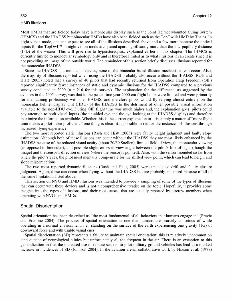
Chapter 12 552
HMD illusions Most HMDs that are fielded today have a monocular display such as the Joint Helmet Mounted Cuing System (JHMCS) and the IHADSS but binocular HMDs have also been fielded such as the TopOwl® HMD by Thales. In night vision mode, one can expect to see all of the illusions described above and a few more because the optical inputs for the TopOwl™ in night vision mode are spaced apart significantly more than the interpupillary distance (IPD) of the wearer. This will give rise to hyperstereopsis, explained earlier in this chapter. The JHMCS is currently limited to monocular symbology only and is therefore limited as to what illusions it can create since it is not providing an image of the outside world. The remainder of this section briefly discusses illusions reported for the monocular IHADSS. Since the IHADSS is a monocular device, none of the binocular-based illusion mechanisms can occur. Also, the majority of illusions reported when using the IHADSS probably also occur without the IHADSS. Rash and Hiatt (2005) noted that a survey of 40 pilots that had recently returned from Operation Iraqi Freedom (OIF) reported significantly fewer instances of static and dynamic illusions for the IHADSS compared to a previous survey conducted in 2000 (n = 216 for this survey). The explanation for the difference, as suggested by the aviators in the 2005 survey, was that in the peace-time year 2000 era flight hours were limited and were primarily for maintaining proficiency with the IHADSS, and therefore pilots would fly relying almost entirely on the monocular helmet display unit (HDU) of the IHADSS to the detriment of other possible visual information available to the non-HDU eye. During OIF flight time was much higher and, the explanation goes, pilots could pay attention to both visual inputs (the un-aided eye and the eye looking at the IHADSS display) and therefore maximize the information available. Whether this is the correct explanation or it is simply a matter of “more flight time makes a pilot more proficient,” one thing is clear: it is possible to reduce the instances of illusions through increased flying experience. The two most reported static illusions (Rash and Hiatt, 2005) were faulty height judgment and faulty slope estimation. Although both of these illusions can occur without the IHADSS they are most likely enhanced by the IHADSS because of the reduced visual acuity (about 20/60 Snellen), limited field of view, the monocular viewing (as opposed to binocular), and possible slight errors in view angle between the pilot’s line of sight (though the image) and the sensor’s direction of view (where the sensor is pointed). Also, with the sensor mounted so far from where the pilot’s eyes, the pilot must mentally compensate for the shifted view point, which can lead to height and slope misperceptions. The two most reported dynamic illusions (Rash and Hiatt, 2005) were undetected drift and faulty closure judgment. Again, these can occur when flying without the IHADSS but are probably enhanced because of all of the same limitations listed above. This section on NVG and HMD illusions was intended to provide a sampling of some of the types of illusions that can occur with these devices and is not a comprehensive treatise on the topic. Hopefully, it provides some insights into the types of illusions, and their root causes, that are actually reported by aircrew members when operating with NVGs and HMDs. Spatial Disorientation Spatial orientation has been described as “the most fundamental of all behaviors that humans engage in” (Previc and Ercoline 2004). The process of spatial orientation is one that humans are scarcely conscious of while operating in a normal environment, i.e., standing on the surface of the earth experiencing one gravity (1G) of downward force and with usable visual cues. Spatial disorientation (SD) represents a failure to maintain spatial orientation; this is relatively uncommon on land outside of neurological clinics but unfortunately all too frequent in the air. There is an exception to this generalization in that the increased use of remote sensors to pilot military ground vehicles has lead to a marked increase in incidences of SD (Johnson 2004). In the aviation arena, collaborative work by Hixson et al. (1977)
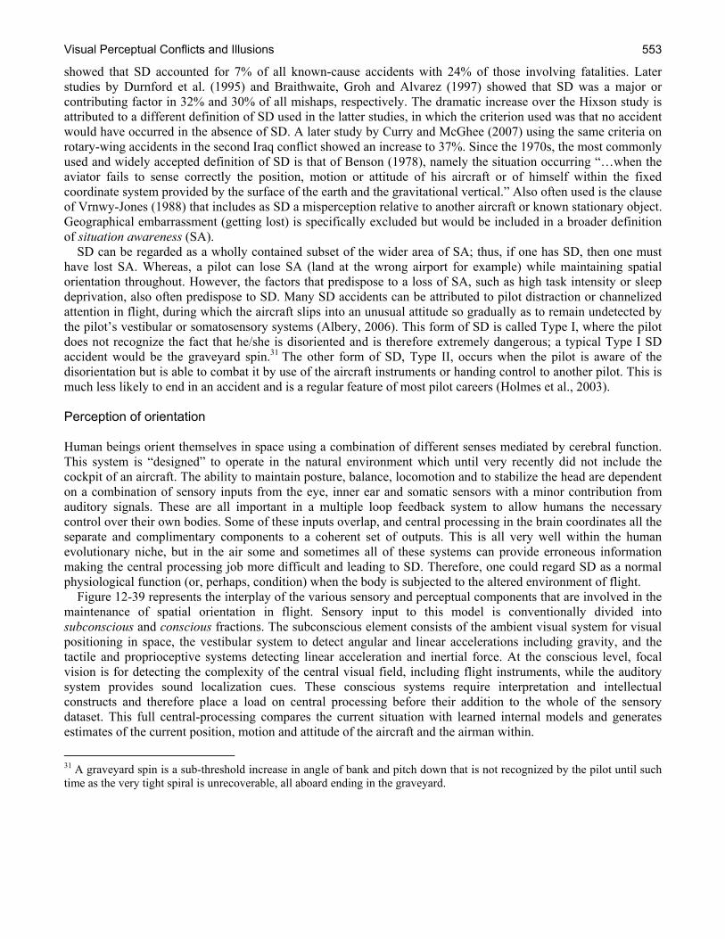
Visual Perceptual Conflicts and Illusions 553
showed that SD accounted for 7% of all known-cause accidents with 24% of those involving fatalities. Later studies by Durnford et al. (1995) and Braithwaite, Groh and Alvarez (1997) showed that SD was a major or contributing factor in 32% and 30% of all mishaps, respectively. The dramatic increase over the Hixson study is attributed to a different definition of SD used in the latter studies, in which the criterion used was that no accident would have occurred in the absence of SD. A later study by Curry and McGhee (2007) using the same criteria on rotary-wing accidents in the second Iraq conflict showed an increase to 37%. Since the 1970s, the most commonly used and widely accepted definition of SD is that of Benson (1978), namely the situation occurring “…when the aviator fails to sense correctly the position, motion or attitude of his aircraft or of himself within the fixed coordinate system provided by the surface of the earth and the gravitational vertical.” Also often used is the clause of Vrnwy-Jones (1988) that includes as SD a misperception relative to another aircraft or known stationary object. Geographical embarrassment (getting lost) is specifically excluded but would be included in a broader definition of situation awareness (SA). SD can be regarded as a wholly contained subset of the wider area of SA; thus, if one has SD, then one must have lost SA. Whereas, a pilot can lose SA (land at the wrong airport for example) while maintaining spatial orientation throughout. However, the factors that predispose to a loss of SA, such as high task intensity or sleep deprivation, also often predispose to SD. Many SD accidents can be attributed to pilot distraction or channelized attention in flight, during which the aircraft slips into an unusual attitude so gradually as to remain undetected by the pilot’s vestibular or somatosensory systems (Albery, 2006). This form of SD is called Type I, where the pilot does not recognize the fact that he/she is disoriented and is therefore extremely dangerous; a typical Type I SD accident would be the graveyard spin.31 The other form of SD, Type II, occurs when the pilot is aware of the disorientation but is able to combat it by use of the aircraft instruments or handing control to another pilot. This is much less likely to end in an accident and is a regular feature of most pilot careers (Holmes et al., 2003). Perception of orientation Human beings orient themselves in space using a combination of different senses mediated by cerebral function. This system is “designed” to operate in the natural environment which until very recently did not include the cockpit of an aircraft. The ability to maintain posture, balance, locomotion and to stabilize the head are dependent on a combination of sensory inputs from the eye, inner ear and somatic sensors with a minor contribution from auditory signals. These are all important in a multiple loop feedback system to allow humans the necessary control over their own bodies. Some of these inputs overlap, and central processing in the brain coordinates all the separate and complimentary components to a coherent set of outputs. This is all very well within the human evolutionary niche, but in the air some and sometimes all of these systems can provide erroneous information making the central processing job more difficult and leading to SD. Therefore, one could regard SD as a normal physiological function (or, perhaps, condition) when the body is subjected to the altered environment of flight. Figure 12-39 represents the interplay of the various sensory and perceptual components that are involved in the maintenance of spatial orientation in flight. Sensory input to this model is conventionally divided into subconscious and conscious fractions. The subconscious element consists of the ambient visual system for visual positioning in space, the vestibular system to detect angular and linear accelerations including gravity, and the tactile and proprioceptive systems detecting linear acceleration and inertial force. At the conscious level, focal vision is for detecting the complexity of the central visual field, including flight instruments, while the auditory system provides sound localization cues. These conscious systems require interpretation and intellectual constructs and therefore place a load on central processing before their addition to the whole of the sensory dataset. This full central-processing compares the current situation with learned internal models and generates estimates of the current position, motion and attitude of the aircraft and the airman within.
31 A graveyard spin is a sub-threshold increase in angle of bank and pitch down that is not recognized by the pilot until such time as the very tight spiral is unrecoverable, all aboard ending in the graveyard.
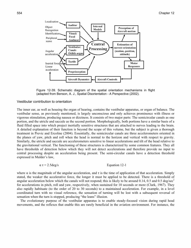
Chapter 12 554
Figure 12-39. Schematic diagram of the spatial orientation mechanisms in flight (adapted from Benson, A. J., Spatial Disorientation - A Perspective (2002).
Vestibular contribution to orientation The inner ear, as well as housing the organ of hearing, contains the vestibular apparatus, or organ of balance. The vestibular sense, as previously mentioned, is largely unconscious and only achieves prominence with illness or vigorous stimulation, producing nausea or dizziness. It consists of two major parts: The semicircular canals as one portion, and the utricle and saccule as the second portion. Morphologically, both portions have a similar basis of a fluid filled space into which project inertially sensitive structures that are attached to nerves leading to the brain. A detailed explanation of their function is beyond the scope of this volume, but the subject is given a thorough treatment in Previc and Ercoline (2004). Essentially, the semicircular canals are three accelerometers oriented in the planes of yaw, pitch and roll when the head is normal to the horizon and vertical with respect to gravity. Similarly, the utricle and saccule are accelerometers sensitive to linear accelerations and tilt of the head relative to the gravitational vertical. The functioning of these structures is characterized by some common features. They all have thresholds of detection below which they will not detect accelerations and therefore provide no input to central processing despite an acceleration being present. The semi-circular canals have a detection threshold expressed in Mulder’s law, α τ = 2.5deg/s Equation 12-1 where α is the magnitude of the angular acceleration, and τ is the time of application of that acceleration. Simply stated, the weaker the accelerative force, the longer it must be applied to be detected. There is a threshold of angular acceleration below which the canals will not respond; this is likely to be around 0.14, 0.5 and 0.5 deg/sec2 for accelerations in pitch, roll and yaw, respectively, when sustained for 10 seconds or more (Clark, 1967). They also rapidly habituate (to the order of 20 to 30 seconds) to a maintained acceleration. For example, in a level coordinated turn with no visual reference, the sensation of turning will be lost with a subsequent reversal of sensation when the turn is stopped, producing “the leans” illusion. The evolutionary purpose of the vestibular apparatus is to enable steady-focused vision during rapid head movements, and the reflexes that enable this are rarely beneficial in the aviation environment. For instance, the

Visual Perceptual Conflicts and Illusions 555
counter-rotation illusion described above can lead to nystagmus, an involuntary oculomotor response that destabilizes the retinal image. The utricle and saccule (collectively known as the otolith organ) function in a similar manner to the semi-circular canals but detect linear rather than angular accelerations. They are also responsible for our sensation of gravity and therefore have a baseline level of activity providing the vertical reference up. In zero-G environments, it is not unusual for individuals to feel upside down when they are not – a potent source of motion sickness. In a normal gravitational environment, the otolith organ also senses the attitude of the head relative to the gravitational vertical. This can lead to problems in the flight environment, as this means that the otolith organ cannot differentiate between a head tilt and a sustained linear acceleration (Figure 12-40). Many aircraft have been lost in conditions of limited visibility when a take-off (+GX) acceleration was misperceived as a backward head tilt, hence pitch up and a forward correction applied to the controls resulting in a nose-over into the ground or sea. This is known as the somatogravic illusion. The otolith organ does have a detection threshold, but there is a wide variation in values quoted (Guedry, 1974). The most accepted values for detection of sustained linear acceleration are 0.01 m/sec2 (0.03 feet/sec2 or 0.001G) for a supine subject and 0.06 m/sec2 (0.20 feet/sec2 or 0.006G) for an erect subject (Meiry, 1965). This is a very fine level of detection, and for all practical aviation purposes the otolith organ will detect all translational accelerations. However, the organ does not detect linear velocity so is of no utility, for instance, in detecting the ongoing drift of a hovering helicopter once the initial acceleration has stopped.
Upright Backward Head Tilt Forward Acceleration Figure 12-40. With gravity coming from directly above, the otolith organ will detect head tilt and acceleration as producing the same resultant gravitational vector.
One of the primary roles of the vestibular system is stabilization of the retinal image. This allows humans to simultaneously move through their environment and be able to continue to see what they are looking at. In normal circumstances, vision provides approximately 85% of our orientation information; unfortunately, the aviation environment cannot be described as normal. The dynamic milieu of flight can produce problems with image stabilization, and visual acuity starts to fall when the velocity of inappropriate eye movements exceeds 3° to 5°/second. Clearly, if there was no compensatory reflex, then head movements, which tend to be of high frequency, would disturb vision. The relatively slow retinal processing (around 70 ms) cannot compensate for head movement, but the vestibular system via the vestibulo-ocular reflex (VOR) with latency of less than 16 ms can. The VOR has been quantified in the three dimensions of pitch, roll and yaw and has been shown to relate back to the gravitational vertical rather than the head orientation after perturbation, indicating a central processing function after the pure reflex of the VOR (Angaleski and Hess, 1994; Merfield et al., 1993). In other words, stabilization of the VOR functions for Earth-fixed but not head-fixed targets (Cheung, 2004). This presents a problem in flight as the aircraft movements are often of high rate and amplitude resulting in the breakdown of the

Chapter 12 556
combination of vestibulo-ocular and optokinetic mechanisms and the destabilization of the retinal image. For instance, prolonged rotational stimulation with a sudden cessation can lead to rotational nystagmus and the disruption of vision. Nystagmus is the flicking of the eye in a plane of movement and is named for the fast phase. In an initial acceleration to the right, the eyes drift to the left (slow phase). As the rotation continues, the eyes flick back to the right (fast phase) and then start the slow drift to the left again. This is a normal part of the stabilization mechanism of gaze, also seen in ice skaters. Unfortunately, when the sustained turn is stopped, there is an initiation of a reverse nystagmus due to the inability of the vestibular system to detect sustained velocity. This reverse nystagmus can be severe enough to make fixation on instruments or the outside scene impossible and lead to significant spatial disorientation. Tactile and proprioceptive contribution to orientation The somatosensory system is a widespread and diverse sensory system comprised of the receptors and processing centers that process touch, temperature, proprioception (body position), and nociception (pain). It consists of cutaneous tactile sensors and proprioceptors in muscles, ligaments, tendons and joint capsules. Together these sensors provide information on the body’s orientation with respect to gravity and influence numerous force-feedback loops that help to determine conscious and unconscious muscular action to maintain that orientation. They are also fundamental in the everyday activities of movement and fine motor control. Thus, the output from these sensors is both pervasive and powerful and led aviators to the impression that they could “fly by the seat of their pants.” Unfortunately, these somatosensors are as vulnerable to confusion in the flight environment as is the vestibular system. Consider an aircraft accelerating in the longitudinal axis at 2G, the tactile sensation on the skin of the pilot’s back is exactly the same as in an aircraft accelerating vertically at 1G. In addition to this basic problem, the nature of the sensors themselves can produce erroneous orientation information. One special sensor in skeletal muscle is called the spindle, which is particularly sensitive to stretch. The amount of its activity is crucial to our knowledge of where our limbs are. Experiments have shown that under conditions of vibration (Goodwin, McCloskey and Matthews, 1972) or high G turning (Lackner and Levine, 1979), the spindles produce erroneous information leading to an uncertainty as to the position of our limbs. There are several other sensory inputs from muscle, tendon and joint capsule that all detect stretch, compression and activity and therefore provide information to central processing. All of these can and do provide inaccurate information under one or other circumstance of the flight environment. In the event that a pilot has no dependable visual references, the somatosensory and vestibular systems both provide information that can either confuse or override the other. The unusual force patterns of some flight maneuvers that stimulate vestibular illusions also stimulate somatosensors to provide the brain with an altered perception of orientation and even a changed feel of the aircraft controls (Lackner and Dizio, 1989). All of the somatosensors are likely to produce misleading information to the brain when exposed to the altered gravitational environment of flight, particularly in rotary-wing flight with six degrees of freedom. A system produced by evolution to provide powerful unconscious information regarding body position and motor control while in the 1G environment on the earth’s surface may not function appropriately in an aircraft. The very power of these stimuli is a cause of disorientation in flight without visual cues and should convince any pilot that they cannot fly “by the seat of their pants.” Auditory contribution to orientation The human auditory system gathers sound information and passes it to the auditory cortex in the brain for interpretation. One of the system’s functions is to localize sound and this is achieved by detecting the differences in sound intensity and time of arrival incident on the ears, all facilitated by the shape of the external ear (Batteau, 1974). The predominant portion of sound that contributes to its localization is the low frequency sound and its interaural time difference (Wightman and Kistler, 1992), which is that portion of the audible sound spectrum that
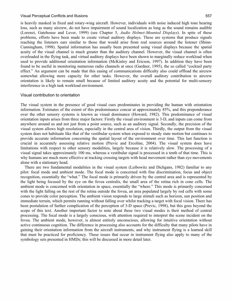
Visual Perceptual Conflicts and Illusions 557
is heavily masked in fixed and rotary-wing aircraft. However, individuals with noise induced high tone hearing loss, such as many aircrew, do not have impairment of sound localization as long as the sound remains audible (Lorenzi, Gatehouse and Lever, 1999) (see Chapter 5, Audio Helmet-Mounted Displays). In spite of these problems, efforts have been made to create virtual auditory displays. These are systems that produce signals reaching the listeners ears similar to those that would arise from real sources around the listener (Shinn-Cunningham, 1998). Spatial information has usually been presented using visual displays because the spatial acuity of the visual channel is much greater than the auditory channel. However, the visual channel is often overloaded in the flying task, and virtual auditory displays have been shown to marginally reduce workload when used to provide additional orientation information (McKinley and Ericson, 1997). In addition they have been found to be useful in monitoring numerous radio channels at once (Gardner, 1995), the so called “cocktail party effect.” An argument can be made that this easing of communications difficulty also could offload the aircrew somewhat allowing more capacity for other tasks. However, the overall auditory contribution to aircrew orientation is likely to remain small because of limited auditory acuity and the potential for multi-sensory interference in a high task workload environment. Visual contribution to orientation The visual system in the presence of good visual cues predominates in providing the human with orientation information. Estimates of the extent of this predominance concur at approximately 85%, and this preponderance over the other sensory systems is known as visual dominance (Howard, 1982). This predominance of visual orientation inputs arises from three major factors: Firstly the visual environment is 3-D, and inputs can come from anywhere around us and not just from a point source, such as an auditory signal. Secondly, the precision of the visual system allows high resolution, especially in the central area of vision. Thirdly, the output from the visual system does not habituate like that of the vestibular system when exposed to steady state motion but continues to provide accurate information concerning the spatial layout of the environment over time. This last function is crucial in accurately assessing relative motion (Previc and Ercoline, 2004). The visual system does have limitations with respect to other sensory modalities, largely because it is relatively slow. The processing of a visual signal takes approximately 100 ms, whereas a vestibular signal is processed in a tenth of that time. This is why humans are much more effective at tracking crossing targets with head movement rather than eye movements alone with a stationary head. There are two fundamental modalities in the visual system (Leibowitz and Dichgans, 1982) familiar to any pilot: focal mode and ambient mode. The focal mode is concerned with fine discrimination, focus and object recognition, essentially the “what.” The focal mode is primarily driven by the central area and is represented by the light being focused by the eye on the fovea centralis, the small area of the retina rich in cone cells. The ambient mode is concerned with orientation in space, essentially the “where.” This mode is primarily concerned with the light falling on the rest of the retina outside the fovea, an area populated largely by rod cells with some cones to provide color perception. The ambient vision responds to large stimuli such as horizon, sun position and immediate terrain, which permits running without falling over whilst tracking a target with focal vision. There has been postulation of further complication of the perception of 3-D space (Previc, 1998), but this goes beyond the scope of this text. Another important factor to note about these two visual modes is their method of central processing. The focal mode is a largely conscious, with attention required to interpret the scene incident on the fovea. The ambient mode, however, is almost entirely unconscious, allowing for intuitive orientation without active continuous cognition. The difference in processing also accounts for the difficulty that many pilots have in gaining their orientation information from the aircraft instruments, and why instrument flying is a learned skill that must be practiced for proficiency. These issues that occur in instrument flying also apply to many of the symbology sets presented in HMDs; this will be discussed in more detail later.
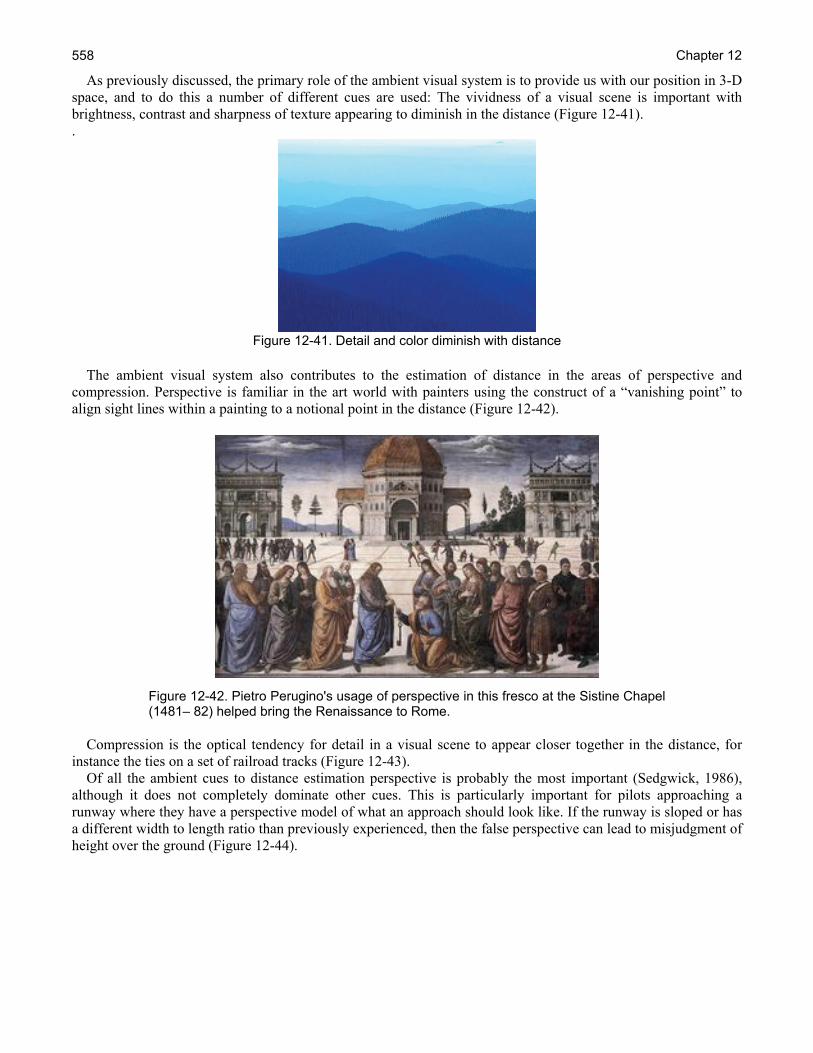
Chapter 12 558
As previously discussed, the primary role of the ambient visual system is to provide us with our position in 3-D space, and to do this a number of different cues are used: The vividness of a visual scene is important with brightness, contrast and sharpness of texture appearing to diminish in the distance (Figure 12-41). .
Figure 12-41. Detail and color diminish with distance
The ambient visual system also contributes to the estimation of distance in the areas of perspective and compression. Perspective is familiar in the art world with painters using the construct of a “vanishing point” to align sight lines within a painting to a notional point in the distance (Figure 12-42).
Figure 12-42. Pietro Perugino's usage of perspective in this fresco at the Sistine Chapel (1481– 82) helped bring the Renaissance to Rome.
Compression is the optical tendency for detail in a visual scene to appear closer together in the distance, for instance the ties on a set of railroad tracks (Figure 12-43). Of all the ambient cues to distance estimation perspective is probably the most important (Sedgwick, 1986), although it does not completely dominate other cues. This is particularly important for pilots approaching a runway where they have a perspective model of what an approach should look like. If the runway is sloped or has a different width to length ratio than previously experienced, then the false perspective can lead to misjudgment of height over the ground (Figure 12-44).

Visual Perceptual Conflicts and Illusions 559
Figure 12-43. Compression and perspective on a set of railroad tracks.
Figure 12-44. The importance of perspective in determining runway slope.
Other key cues are those of motion flow and parallax, which interact with linear perspective to allow the perception of relative motion. All of these cues act within the framework of the surface of the earth and the gravitational vertical supplied visually by the celestial bodies. All of these ambient visual cues are effectively monocular, as anything more than 6 meters (20 feet) away is close to optical infinity, and therefore the incident light rays are effectively parallel. This has important implications for the design of optical displays that attempt to utilize the unconscious ambient system for orientation. A good illustration of the importance of ambient vision in orientation is the autokinetic illusion. In this illusion, a watcher fixates on a small light in an otherwise darkened space. After some minutes, the light will appear to move in a random fashion as the watchers perception of their own orientation breaks down. The visual world changes as humans move through it, and this change is consistent with the observer’s 3-D vector. This apparent motion of the visual surroundings is termed the optical flow field (Gibson, 1966). The optical flow rate of objects in the visual field during motion of the observer can be described as: rate β = ( v / r ) sin β Equation 12-2

Chapter 12 560
where β is the angle of the target from the center of the visual field in degrees, v is the forward velocity, and r is the radial distance to the target. It can be seen that this formula expresses the real world phenomenon that the farther an observer is away from something the slower it appears to be moving. Thus, a jet pilot flying at 400 knots and 200 feet (61 maters) perceives the ground passing at the same rate as a helicopter pilot flying at 120 knots and 60 feet (18.3 meters). This can cause problems for pilots who use this visual cue to judge their height above ground, as their perception will vary with their own velocity. A very familiar illusion is caused by the optical flow field; if there is motion in the field which creates the same retinal image as self-motion through space then there is a misperception of movement. The everyday demonstration if this would be when sitting on a stopped train in a station while another train moves away from the next platform. The perception of movement in the opposite sense to a movement in the optical field is called vection and was first described by Ernst Mach in the late 19th century. Vection can be a particular problem in helicopters hovering close to the ground. The rotor downwash produces movement on the surface of water, in dust/snow or even on a cornfield. This apparent movement is rarely completely radial from the machine and can give rise to a very strong sensation of motion that the pilot may attempt to correct, resulting in drift and a possible accident. Many helicopters have ended flights on their sides as a result of blowing snow or dust and the vection illusion combining with the whiteout or brownout to rob the pilot of a stable visual reference. Vection appears to be a function of the periphery of vision and experiments have shown that the stimulus must be outside the central 50° of regard (Previc and Neel, 1995). Indeed if the object moving in the periphery is concentrated on then the vection disappears. The final feature of vection that is of interest to those involved in SD work is that slower stimuli have a tendency to produce a stronger vection response (Berthoz, Pavard and Young, 1975). The vection response drops off at angular velocities of 60°/sec (1 Hertz), if one imagines the train moving away from the station then there is an initial surge of vection followed by a diminution as the train gets faster. As well as increasing speed diminishing it, the vection response tends to habituate between 10 and 20 seconds after starting, thus making the first few seconds the most disorienting and therefore the most dangerous. Another interesting function of the ambient visual system is that perception of speed is influenced by the nature of what is going past in the optical field (Denton, 1980). A driver on a desert highway will consistently underestimate the vehicle’s speed, whereas a driver on a road through a forest will consistently overestimate. This is due to the relative richness of the visual field and can lead to disorientation and accidents in ground vehicles. The same phenomenon tends to not be an issue for fixed wing pilots but very low level helicopter pilots do encounter it. The predominance of the ambient visual system in framing the human perception of orientation can be problematic in other ways. In some special cases such as those of the Ames rooms, an illusion of a perceptual framework can override the objective evidence provided by the focal vision (Dwyer, Ashton and Broerse, 1990) (Figure 12-45).
Figure 12-45. The Ames room illusion (Dwyer, Ashton and Broerse, 1990).
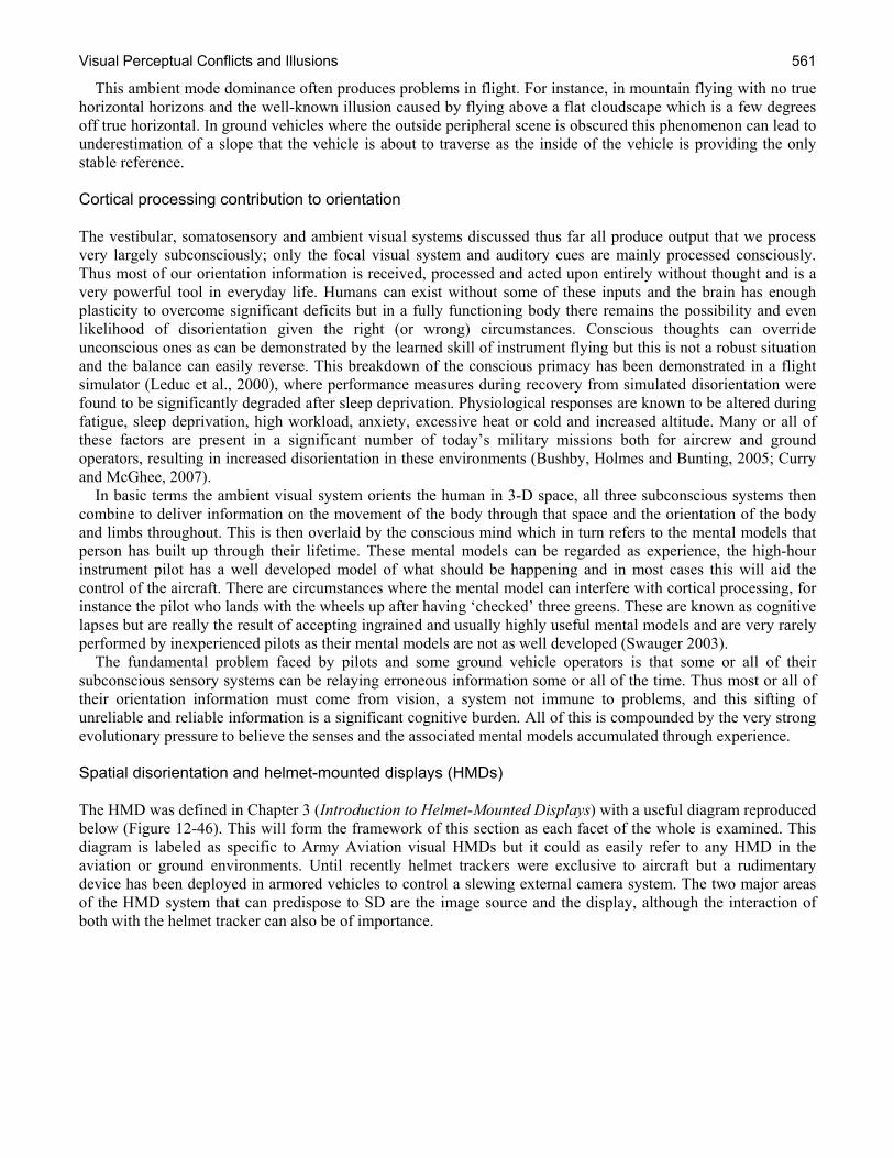
Visual Perceptual Conflicts and Illusions 561
This ambient mode dominance often produces problems in flight. For instance, in mountain flying with no true horizontal horizons and the well-known illusion caused by flying above a flat cloudscape which is a few degrees off true horizontal. In ground vehicles where the outside peripheral scene is obscured this phenomenon can lead to underestimation of a slope that the vehicle is about to traverse as the inside of the vehicle is providing the only stable reference. Cortical processing contribution to orientation The vestibular, somatosensory and ambient visual systems discussed thus far all produce output that we process very largely subconsciously; only the focal visual system and auditory cues are mainly processed consciously. Thus most of our orientation information is received, processed and acted upon entirely without thought and is a very powerful tool in everyday life. Humans can exist without some of these inputs and the brain has enough plasticity to overcome significant deficits but in a fully functioning body there remains the possibility and even likelihood of disorientation given the right (or wrong) circumstances. Conscious thoughts can override unconscious ones as can be demonstrated by the learned skill of instrument flying but this is not a robust situation and the balance can easily reverse. This breakdown of the conscious primacy has been demonstrated in a flight simulator (Leduc et al., 2000), where performance measures during recovery from simulated disorientation were found to be significantly degraded after sleep deprivation. Physiological responses are known to be altered during fatigue, sleep deprivation, high workload, anxiety, excessive heat or cold and increased altitude. Many or all of these factors are present in a significant number of today’s military missions both for aircrew and ground operators, resulting in increased disorientation in these environments (Bushby, Holmes and Bunting, 2005; Curry and McGhee, 2007). In basic terms the ambient visual system orients the human in 3-D space, all three subconscious systems then combine to deliver information on the movement of the body through that space and the orientation of the body and limbs throughout. This is then overlaid by the conscious mind which in turn refers to the mental models that person has built up through their lifetime. These mental models can be regarded as experience, the high-hour instrument pilot has a well developed model of what should be happening and in most cases this will aid the control of the aircraft. There are circumstances where the mental model can interfere with cortical processing, for instance the pilot who lands with the wheels up after having ‘checked’ three greens. These are known as cognitive lapses but are really the result of accepting ingrained and usually highly useful mental models and are very rarely performed by inexperienced pilots as their mental models are not as well developed (Swauger 2003). The fundamental problem faced by pilots and some ground vehicle operators is that some or all of their subconscious sensory systems can be relaying erroneous information some or all of the time. Thus most or all of their orientation information must come from vision, a system not immune to problems, and this sifting of unreliable and reliable information is a significant cognitive burden. All of this is compounded by the very strong evolutionary pressure to believe the senses and the associated mental models accumulated through experience. Spatial disorientation and helmet-mounted displays (HMDs) The HMD was defined in Chapter 3 (Introduction to Helmet-Mounted Displays) with a useful diagram reproduced below (Figure 12-46). This will form the framework of this section as each facet of the whole is examined. This diagram is labeled as specific to Army Aviation visual HMDs but it could as easily refer to any HMD in the aviation or ground environments. Until recently helmet trackers were exclusive to aircraft but a rudimentary device has been deployed in armored vehicles to control a slewing external camera system. The two major areas of the HMD system that can predispose to SD are the image source and the display, although the interaction of both with the helmet tracker can also be of importance.
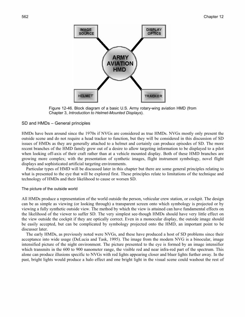
Chapter 12 562
Figure 12-46. Block diagram of a basic U.S. Army rotary-wing aviation HMD (from Chapter 3, Introduction to Helmet-Mounted Displays).
SD and HMDs – General principles HMDs have been around since the 1970s if NVGs are considered as true HMDs. NVGs mostly only present the outside scene and do not require a head tracker to function, but they will be considered in this discussion of SD issues of HMDs as they are generally attached to a helmet and certainly can produce episodes of SD. The more recent branches of the HMD family grew out of a desire to allow targeting information to be displayed to a pilot when looking off-axis of their craft rather than at a vehicle mounted display. Both of these HMD branches are growing more complex; with the presentation of synthetic images, flight instrument symbology, novel flight displays and sophisticated artificial targeting environments. Particular types of HMD will be discussed later in this chapter but there are some general principles relating to what is presented to the eye that will be explored first. These principles relate to limitations of the technique and technology of HMDs and their likelihood to cause or worsen SD. The picture of the outside world All HMDs produce a representation of the world outside the person, vehicular crew station, or cockpit. The design can be as simple as viewing (or looking through) a transparent screen onto which symbology is projected or by viewing a fully synthetic outside view. The method by which the view is attained can have fundamental effects on the likelihood of the viewer to suffer SD. The very simplest see-though HMDs should have very little effect on the view outside the cockpit if they are optically correct. Even in a monocular display, the outside image should be easily accepted, but can be complicated by symbology projected onto the HMD, an important point to be discusser later. The early HMDs, as previously noted were NVGs, and these have produced a host of SD problems since their acceptance into wide usage (DeLucia and Task, 1995). The image from the modern NVG is a binocular, image intensified picture of the night environment. The picture presented to the eye is formed by an image intensifier which transmits in the 600 to 900 nanometer range, the visible red and near infra-red part of the spectrum. This alone can produce illusions specific to NVGs with red lights appearing closer and bluer lights further away. In the past, bright lights would produce a halo effect and one bright light in the visual scene could washout the rest of
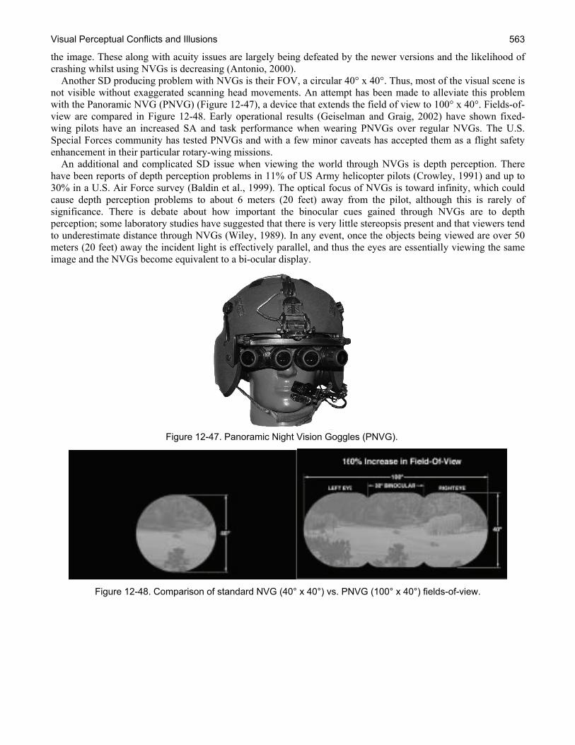
Visual Perceptual Conflicts and Illusions 563
the image. These along with acuity issues are largely being defeated by the newer versions and the likelihood of crashing whilst using NVGs is decreasing (Antonio, 2000). Another SD producing problem with NVGs is their FOV, a circular 40° x 40°. Thus, most of the visual scene is not visible without exaggerated scanning head movements. An attempt has been made to alleviate this problem with the Panoramic NVG (PNVG) (Figure 12-47), a device that extends the field of view to 100° x 40°. Fields-of-view are compared in Figure 12-48. Early operational results (Geiselman and Graig, 2002) have shown fixed-wing pilots have an increased SA and task performance when wearing PNVGs over regular NVGs. The U.S. Special Forces community has tested PNVGs and with a few minor caveats has accepted them as a flight safety enhancement in their particular rotary-wing missions. An additional and complicated SD issue when viewing the world through NVGs is depth perception. There have been reports of depth perception problems in 11% of US Army helicopter pilots (Crowley, 1991) and up to 30% in a U.S. Air Force survey (Baldin et al., 1999). The optical focus of NVGs is toward infinity, which could cause depth perception problems to about 6 meters (20 feet) away from the pilot, although this is rarely of significance. There is debate about how important the binocular cues gained through NVGs are to depth perception; some laboratory studies have suggested that there is very little stereopsis present and that viewers tend to underestimate distance through NVGs (Wiley, 1989). In any event, once the objects being viewed are over 50 meters (20 feet) away the incident light is effectively parallel, and thus the eyes are essentially viewing the same image and the NVGs become equivalent to a bi-ocular display.
Figure 12-47. Panoramic Night Vision Goggles (PNVG).
Figure 12-48. Comparison of standard NVG (40° x 40°) vs. PNVG (100° x 40°) fields-of-view.
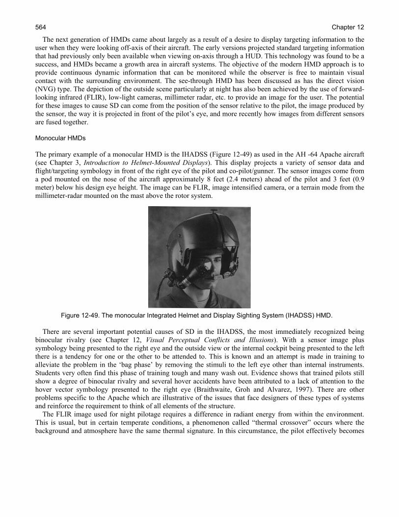
Chapter 12 564
The next generation of HMDs came about largely as a result of a desire to display targeting information to the user when they were looking off-axis of their aircraft. The early versions projected standard targeting information that had previously only been available when viewing on-axis through a HUD. This technology was found to be a success, and HMDs became a growth area in aircraft systems. The objective of the modern HMD approach is to provide continuous dynamic information that can be monitored while the observer is free to maintain visual contact with the surrounding environment. The see-through HMD has been discussed as has the direct vision (NVG) type. The depiction of the outside scene particularly at night has also been achieved by the use of forward-looking infrared (FLIR), low-light cameras, millimeter radar, etc. to provide an image for the user. The potential for these images to cause SD can come from the position of the sensor relative to the pilot, the image produced by the sensor, the way it is projected in front of the pilot’s eye, and more recently how images from different sensors are fused together. Monocular HMDs The primary example of a monocular HMD is the IHADSS (Figure 12-49) as used in the AH -64 Apache aircraft (see Chapter 3, Introduction to Helmet-Mounted Displays). This display projects a variety of sensor data and flight/targeting symbology in front of the right eye of the pilot and co-pilot/gunner. The sensor images come from a pod mounted on the nose of the aircraft approximately 8 feet (2.4 meters) ahead of the pilot and 3 feet (0.9 meter) below his design eye height. The image can be FLIR, image intensified camera, or a terrain mode from the millimeter-radar mounted on the mast above the rotor system.
Figure 12-49. The monocular Integrated Helmet and Display Sighting System (IHADSS) HMD.
There are several important potential causes of SD in the IHADSS, the most immediately recognized being binocular rivalry (see Chapter 12, Visual Perceptual Conflicts and Illusions). With a sensor image plus symbology being presented to the right eye and the outside view or the internal cockpit being presented to the left there is a tendency for one or the other to be attended to. This is known and an attempt is made in training to alleviate the problem in the ‘bag phase’ by removing the stimuli to the left eye other than internal instruments. Students very often find this phase of training tough and many wash out. Evidence shows that trained pilots still show a degree of binocular rivalry and several hover accidents have been attributed to a lack of attention to the hover vector symbology presented to the right eye (Braithwaite, Groh and Alvarez, 1997). There are other problems specific to the Apache which are illustrative of the issues that face designers of these types of systems and reinforce the requirement to think of all elements of the structure. The FLIR image used for night pilotage requires a difference in radiant energy from within the environment. This is usual, but in certain temperate conditions, a phenomenon called “thermal crossover” occurs where the background and atmosphere have the same thermal signature. In this circumstance, the pilot effectively becomes
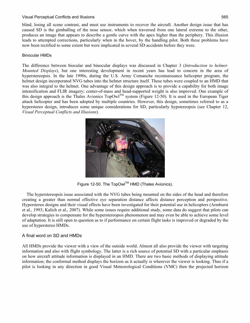
Visual Perceptual Conflicts and Illusions 565
blind, losing all scene contrast, and must use instruments to recover the aircraft. Another design issue that has caused SD is the gimballing of the nose sensor, which when traversed from one lateral extreme to the other, produces an image that appears to describe a gentle curve with the apex higher than the periphery. This illusion leads to attempted corrections, particularly when in the hover, by the handling pilot. Both these problems have now been rectified to some extent but were implicated in several SD accidents before they were. Binocular HMDs The difference between biocular and binocular displays was discussed in Chapter 3 (Introduction to helmet-Mounted Displays), but one interesting development in recent years has lead to concern in the area of hyperstereopsis. In the late 1990s, during the U.S. Army Comanche reconnaissance helicopter program, the helmet design incorporated NVG tubes into the helmet structure itself. These tubes were coupled to an HMD that was also integral to the helmet. One advantage of this design approach is to provide a capability for both image intensification and FLIR imagery; center-of-mass and head-supported weight is also improved. One example of this design approach is the Thales Avionics TopOwlTM system (Figure 12-50). It is used in the European Tiger attack helicopter and has been adopted by multiple countries. However, this design, sometimes referred to as a hyperstereo design, introduces some unique considerations for SD, particularly hypstereopsis (see Chapter 12, Visual Perceptual Conflicts and Illusions).
Figure 12-50. The TopOwlTM HMD (Thales Avionics).
The hyperstereopsis issue associated with the NVG tubes being mounted on the sides of the head and therefore creating a greater than normal effective eye separation distance affects distance perception and perspective. Hyperstereo designs and their visual effects have been investigated for their potential use in helicopters (Armburst et al., 1993; Kalich et al., 2007). While some issues require additional study, some data do suggest that pilots can develop strategies to compensate for the hyperstereopsis phenomenon and may even be able to achieve some level of adaptation. It is still open to question as to if performance on certain flight tasks is improved or degraded by the use of hyperstereo HMDs. A final word on SD and HMDs All HMDs provide the viewer with a view of the outside world. Almost all also provide the viewer with targeting information and also with flight symbology. The latter is a rich source of potential SD with a particular emphasis on how aircraft attitude information is displayed in an HMD. There are two basic methods of displaying attitude information; the conformal method displays the horizon as it actually is wherever the viewer is looking. Thus if a pilot is looking in any direction in good Visual Meteorological Conditions (VMC) then the projected horizon
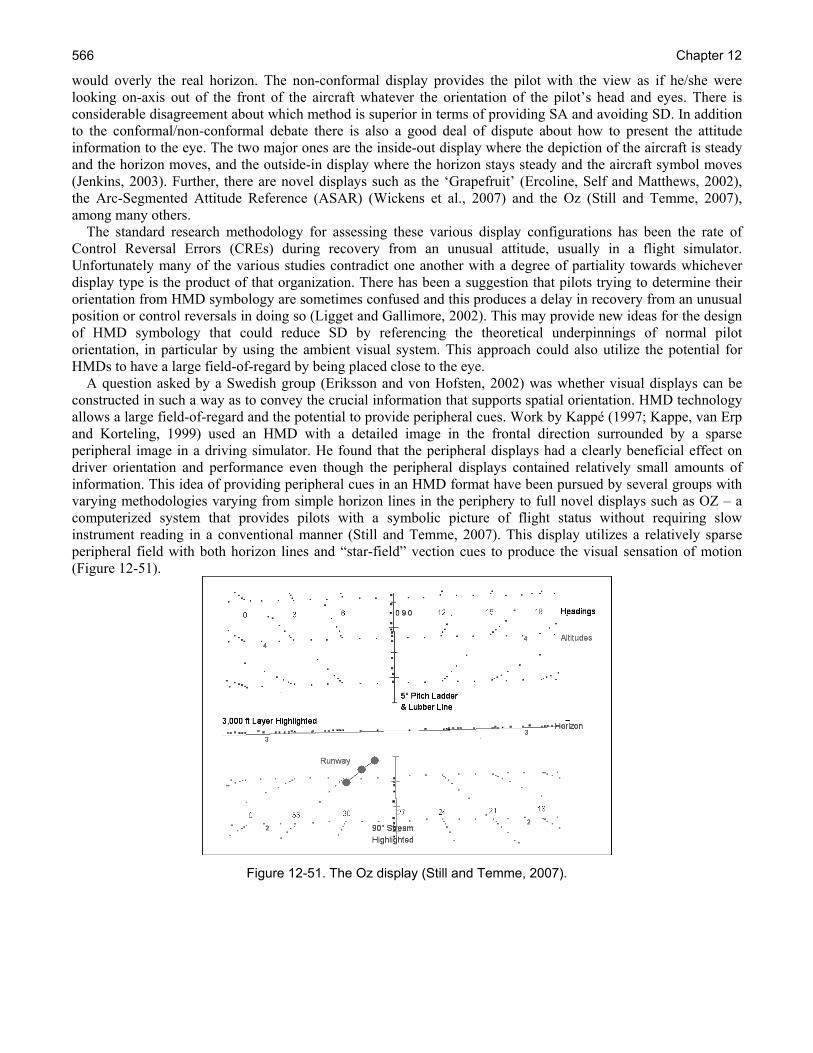
Chapter 12 566
would overly the real horizon. The non-conformal display provides the pilot with the view as if he/she were looking on-axis out of the front of the aircraft whatever the orientation of the pilot’s head and eyes. There is considerable disagreement about which method is superior in terms of providing SA and avoiding SD. In addition to the conformal/non-conformal debate there is also a good deal of dispute about how to present the attitude information to the eye. The two major ones are the inside-out display where the depiction of the aircraft is steady and the horizon moves, and the outside-in display where the horizon stays steady and the aircraft symbol moves (Jenkins, 2003). Further, there are novel displays such as the ‘Grapefruit’ (Ercoline, Self and Matthews, 2002), the Arc-Segmented Attitude Reference (ASAR) (Wickens et al., 2007) and the Oz (Still and Temme, 2007), among many others. The standard research methodology for assessing these various display configurations has been the rate of Control Reversal Errors (CREs) during recovery from an unusual attitude, usually in a flight simulator. Unfortunately many of the various studies contradict one another with a degree of partiality towards whichever display type is the product of that organization. There has been a suggestion that pilots trying to determine their orientation from HMD symbology are sometimes confused and this produces a delay in recovery from an unusual position or control reversals in doing so (Ligget and Gallimore, 2002). This may provide new ideas for the design of HMD symbology that could reduce SD by referencing the theoretical underpinnings of normal pilot orientation, in particular by using the ambient visual system. This approach could also utilize the potential for HMDs to have a large field-of-regard by being placed close to the eye. A question asked by a Swedish group (Eriksson and von Hofsten, 2002) was whether visual displays can be constructed in such a way as to convey the crucial information that supports spatial orientation. HMD technology allows a large field-of-regard and the potential to provide peripheral cues. Work by Kappé (1997; Kappe, van Erp and Korteling, 1999) used an HMD with a detailed image in the frontal direction surrounded by a sparse peripheral image in a driving simulator. He found that the peripheral displays had a clearly beneficial effect on driver orientation and performance even though the peripheral displays contained relatively small amounts of information. This idea of providing peripheral cues in an HMD format have been pursued by several groups with varying methodologies varying from simple horizon lines in the periphery to full novel displays such as OZ – a computerized system that provides pilots with a symbolic picture of flight status without requiring slow instrument reading in a conventional manner (Still and Temme, 2007). This display utilizes a relatively sparse peripheral field with both horizon lines and “star-field” vection cues to produce the visual sensation of motion (Figure 12-51).
Figure 12-51. The Oz display (Still and Temme, 2007).
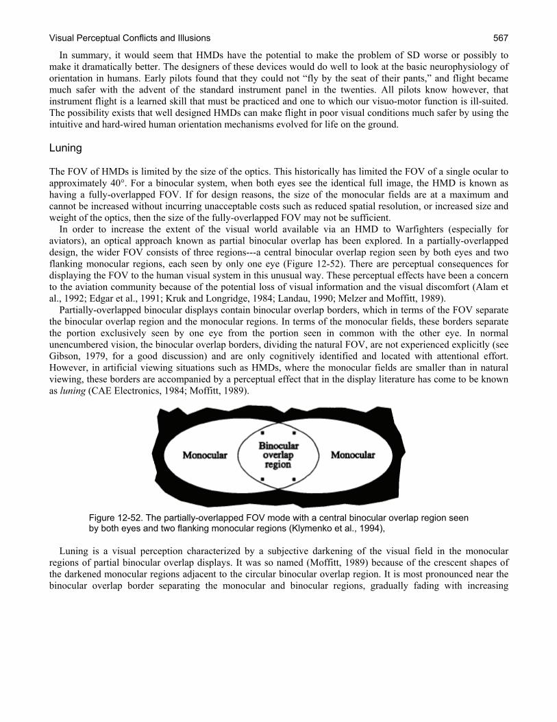
Visual Perceptual Conflicts and Illusions 567
In summary, it would seem that HMDs have the potential to make the problem of SD worse or possibly to make it dramatically better. The designers of these devices would do well to look at the basic neurophysiology of orientation in humans. Early pilots found that they could not “fly by the seat of their pants,” and flight became much safer with the advent of the standard instrument panel in the twenties. All pilots know however, that instrument flight is a learned skill that must be practiced and one to which our visuo-motor function is ill-suited. The possibility exists that well designed HMDs can make flight in poor visual conditions much safer by using the intuitive and hard-wired human orientation mechanisms evolved for life on the ground. Luning The FOV of HMDs is limited by the size of the optics. This historically has limited the FOV of a single ocular to approximately 40°. For a binocular system, when both eyes see the identical full image, the HMD is known as having a fully-overlapped FOV. If for design reasons, the size of the monocular fields are at a maximum and cannot be increased without incurring unacceptable costs such as reduced spatial resolution, or increased size and weight of the optics, then the size of the fully-overlapped FOV may not be sufficient. In order to increase the extent of the visual world available via an HMD to Warfighters (especially for aviators), an optical approach known as partial binocular overlap has been explored. In a partially-overlapped design, the wider FOV consists of three regions---a central binocular overlap region seen by both eyes and two flanking monocular regions, each seen by only one eye (Figure 12-52). There are perceptual consequences for displaying the FOV to the human visual system in this unusual way. These perceptual effects have been a concern to the aviation community because of the potential loss of visual information and the visual discomfort (Alam et al., 1992; Edgar et al., 1991; Kruk and Longridge, 1984; Landau, 1990; Melzer and Moffitt, 1989). Partially-overlapped binocular displays contain binocular overlap borders, which in terms of the FOV separate the binocular overlap region and the monocular regions. In terms of the monocular fields, these borders separate the portion exclusively seen by one eye from the portion seen in common with the other eye. In normal unencumbered vision, the binocular overlap borders, dividing the natural FOV, are not experienced explicitly (see Gibson, 1979, for a good discussion) and are only cognitively identified and located with attentional effort. However, in artificial viewing situations such as HMDs, where the monocular fields are smaller than in natural viewing, these borders are accompanied by a perceptual effect that in the display literature has come to be known as luning (CAE Electronics, 1984; Moffitt, 1989).
Figure 12-52. The partially-overlapped FOV mode with a central binocular overlap region seen by both eyes and two flanking monocular regions (Klymenko et al., 1994),
Luning is a visual perception characterized by a subjective darkening of the visual field in the monocular regions of partial binocular overlap displays. It was so named (Moffitt, 1989) because of the crescent shapes of the darkened monocular regions adjacent to the circular binocular overlap region. It is most pronounced near the binocular overlap border separating the monocular and binocular regions, gradually fading with increasing

Chapter 12 568
distance from the border. The prominence of luning fluctuates over time and appears not to be strongly under attentional control (see Figure 12-53).
Figure 12-53. Luning in partial-overlap HMDs (Rash, 2001).
Luning may be related to binocular rivalry and suppression. Binocular rivalry refers to the alterations in the appearance of a binocular stimulus which is dichoptic, i.e., where each eye’s image alternately dominates the phenomenal binocular FOV by suppressing the other eye’s input. Over time, one and then the other eye may successfully compete and dominate awareness. Suppression refers to the phenomenal disappearance of one eye’s input due to monocular dominance by the other eye. Partial suppression refers to the partial disappearance of one eye’s input. In the partial binocular overlap display mode, each eye’s monocular region is the result of dichoptic competition between a portion of its monocular field and the other eye’s monocular field border and dark background. If the background is completely suppressed, the total FOV looks natural, where the binocular and monocular regions are both seen as one continuous visual world. If an eye’s monocular region is partially suppressed by the dark background of the other eye, then this dark background will appear in monocular regions of the first eye with the greatest darkening – luning – occurring near the binocular overlap border. In the monocular regions of partial binocular overlap displays, both the dichoptic differences in luminance and the presence of the monocular edge—the luminance drop--at the binocular overlap border likely affect luning. This luminance transition between the monocular field and the background occurs in what we shall refer to as the noninformational eye. During fusion it is matched to a region within the monocular field of the informational eye. There are a number of interocular inhibitory processes in addition to binocular rivalry of dichoptic stimuli (Fox, 1991), which may also contribute to luning (e.g., see Gur, 1991, on Ganzfeld fade-out and blackout, and Bolanowski and Doty, 1987, on blankout). Binocular rivalry and the interocular inhibitory process of suppression due to rivalry between dichoptic stimuli is can be one working hypothesis of luning. There are different types of binocular rivalry including piecemeal dominance, binocular superimposition, and binocular transparency (Yang, Rose and Blake, 1992). Binocular transparency describes the percept when both dichoptic stimuli are seen simultaneously, but appear “scissioned,” or segregated in depth; superimposition describes the situation in which both dichoptic stimuli appear to occupy the same space; and piecemeal dominance refers to small isolated parts of each eye’s image dominating the binocular percept. Since luning is a change in apparent brightness (a darkening of a region), which can spread or recede overtime, this particular occurrence of binocular rivalry (see Kaufman, 1963) theoretically appears also to be related to the ubiquitous contrast, and color, spreading phenomena (see Grossberg (1987) for a catalogue and neural net theory of such phenomena), such as neon color spreading (see Nakayama, Shimojo and Ramachandran, 1990). Luning appears to emanate from the binocular overlap border and is attenuated by placing physical contours in the location of this border, that is, in the location within the
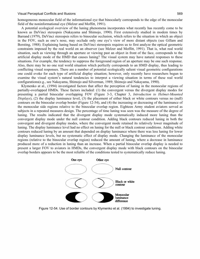
Visual Perceptual Conflicts and Illusions 569
homogeneous monocular field of the informational eye that binocularly corresponds to the edge of the monocular field of the noninformational eye (Melzer and Moffitt, 1991). A potential ecological overview of the luning phenomena incorporates what recently has recently come to be known as DaVinci stereopsis (Nakayama and Shimojo, 1990). First extensively studied in modem times by Barrand (1979), DaVinci stereopsis refers to binocular occlusion, which refers to the situation in which an object in the FOV, such as one’s nose, may occlude only one eye’s view of more distant objects (see Gillam and Borsting, 1988). Explaining luning based on DaVinci stereopsis requires us to first analyze the optical geometric constraints imposed by the real world on an observer (see Melzer and Moffitt, 1991). That is, what real world situation, such as viewing through an aperture or viewing past an object in front of the face, corresponds to the artificial display mode of the HMD that causes luning? The visual system may have natural responses to these situations. For example, the tendency to suppress the foreground region of an aperture may be one such response. Also, there may be no one real world situation which perfectly corresponds to an HMD display, thus leading to conflicting visual responses. There are a number of potential ecologically salient visual geometric configurations one could evoke for each type of artificial display situation; however, only recently have researchers begun to examine the visual system’s natural tendencies to interpret a viewing situation in terms of these real world configurations(e.g., see Nakayama, Shimojo and Silverman, 1989; Shimojo and Nakayama, 1990). Klymenko at al., (1994) investigated factors that affect the perception of luning in the monocular regions of partially-overlapped HMDs. These factors included: (1) the convergent versus the divergent display modes for presenting a partial binocular overlapping FOV (Figure 3-3, Chapter 3, Introduction to Helmet-Mounted Displays), (2) the display luminance level, (3) the placement of either black or white contours versus no (null) contours on the binocular overlap border (Figure 12-54), and (4) the increasing or decreasing of the luminance of the monocular side regions relative to the binocular overlap region. Eighteen Army student aviators served as subjects in a repeated measures design. The percentage of time luning was seen was the measure of the degree of luning. The results indicated that the divergent display mode systematically induced more luning than the convergent display mode under the null contour condition. Adding black contours reduced luning in both the convergent and divergent display modes, where the convergent mode retained its relatively lower magnitude of luning. The display luminance level had no effect on luning for the null or black contour conditions. Adding white contours reduced luning by an amount that depended on display luminance where there was less luning for lower display luminance levels, but no systematic effect of display mode. Changing the luminance of the monocular regions (relative to the binocular overlap region) reduced the amount of luning, where a decrease in luminance produced more of a reduction in luning than an increase. When a partial binocular overlap display is needed to present a larger FOV to aviators in HMDs, the convergent display mode with black contours on the binocular overlap borders appears to be the most reliable of the conditions tested to systematically reduce luning.
Figure 12-54. Use of border contours by Klymenko et al. (1994) to investigate luning.
Chapter 12 570
References Addams, R. (1834) An account of a peculiar optical phenomenon seen after having looked at a moving body.
London and Edinburgh Philosophical. Magazine and Journal of Science, 5, 373–374. Alam, M.S., Zheng, S.H., Iftekharuddin, K.M., and Karim, M.A. (1992). Study of field-of-view overlap for night
vision applications. Proceeding of the 19.92 IEEE National Aerospace and Electronics Conference, NEACON, 3, 1249-1255. Dayton, OH.
Alais, D., and Blake, R. (1999). Grouping visual features during binocular rivalry. Vision Research, 39(26), 4341-4353.
Alais, D., and Blake, R. (Eds.). (2005). Binocular Rivalry. Cambridge, MA: The MIT Press. Albery, W. (2006). Development of Multisensory Orientation Technology for Reducing Spatial Disorientation
Mishaps. AFRL-HE-WP-TR-2006-0024. Alpern, M (1953). Metacontrast. Journal of the Optical Society of America, 43, 648-657. Ames, A. (1951). Visual perception and the rotating trapezoidal window. Psychological Monographs: General
and Applied, 65, No. 324. Andrews, T.J., Sengpiel, F., and Blakemore, C. (2005). From contour to object-face rivalry: multiple neural
mechanisms resolve perceptual ambiguity. Chapter 11. In: Binocular Rivalry, Alais, D., and Blake, R., (Eds.), Cambridge, MA: MIT Press.
Angaleski, D.E., and Hess, B.J.M. (1994). Inertial Representation of Angular Motion in the Vestibular System of Rhesus Monkeys. I. Vestibuloocular Reflex. Journal of Neurophysiology, 71, 1222-1249.
Anstis, S.M. (1974). Letter: A chart demonstrating variations in acuity with retinal position. Vision Research, 14(7), 589-592.
Antonio, J.C. (2000). Reducing NVG-Related Spatial Disorientation Mishaps. Recent Trends in Spatial Disorientation Research. November 15 – 17, San Antonio, Texas.
Armbrust, J., Ros, N., Hale, S., and Rabin, J. (1993). Final report, developmental test (DT) of the Night Vision Pilotage System. Fort Rucker, AL: U.S. Army Aviation Technical Test Center. TECOM Project No. 4-AI-100-RAH-008.
Aulhorn, E., and Harms, H. (1972). Visual perimetry. In: Handbook of Sensory Physiology: Visual Psychophysics VII/4. Jameson, D., and Hurvich , L.M. (Eds.), New York, NY: Springer-Verlag. p 102-145.
Bachmann, T. (1994). Psychophysiology of Visual Masking: The Fine Structure of Conscious Experience. Commack, NY: Nova Science Publishers, Inc.
Baldin, J.B., Dennis, R.J., Ivan, D.J., Miller, R.E., III, Belihar, R.P., Jackson, W.G., Jr, Tredici, T.J., Datko, L.M., and Hiers, P.L. (1999). The 1995 Aircrew Operational Vision Survey: Results, Analysis, and Recommendations. USAF School of Aerospace Medicine, SAM-AF-BR-TR-1999-0003, Brooks Air Force Base, Texas.
Barrand, A.G. (1979). An ecological approach to binocular perception: the neglected facts of occlusion. Doctoral dissertation, Cornell University.
Batteau, D.W. (1964). The Role of the Pinna in Human Sound Localization. Cambridge, MA: United Research Inc.
Benson, A.J. (1978). Spatial Disorientation: General aspects. In: Aviation Medicine. Dhenin, G. (Ed.). London: Tri-Med Books.
Benson, A.J. (2002). Spatial Disorientation – A Perspective. Part of: Spatial Disorientation in Military Vehicles: Causes, Consequences and Cures. RTO-MP-086.
Berthoz, A., Pavard, B., Young, L.R. (1975). Perception of linear horizontal self-motion induced by peripheral vision (Linear vection). Experimental Brain Research, 23, 471-489.
Blake, R., (2008). Retrieved from Vanderbilt University binocular rivalry demonstration website: http://www.psy.vanderbilt.edu/faculty/blake/rivalry/BR.html
Blake, R. (2001). A primer on binocular rivalry, including current controversies. Brain and Mind, 2, 5-38.
Visual Perceptual Conflicts and Illusions 571
Blake , R. (1988). Dichoptic reading: the role of meaning in binocular rivalry. Perception and Psychophysics, 44, 133-141.
Blake, R., and Boothroyd, K. (1985). The precedence of binocular fusion over binocular rivalry. Perception and Psychophysics, 37(2), 114-124.
Blake, R., and Levinson, E. (1977). Spatial properties of binocular neurons in the human visual system. Experimental Brain Research, 27, 221-232.
Blake, R., and Logothetis, N.E. (2002). Visual competition. Nature Reviews Neuroscience, 3, 13-21. Blake, R. (2005). Landmarks in the history of binocular rivalry. Chapter 1. In: Binocular Rivalry, Alais, D., and
Blake, R. (Eds.), (p. 1- 27). Cambridge, MA: MIT Press. Blake, R., Sloane, M., and Fox, R. (1981). Further developments in binocular summation. Perception and
Psychophysics, 30, 266-276. Blake, R., Westendorf, D.H., and Overton, R. (1980). What is suppressed during binocular rivalry? Perception, 9,
223-231. Bolanowski, S.J., and Doty, R.W. (1987). Perceptual “blankout” of monocular Homogeneous fields (Ganzfelder)
is prevented with binocular viewing. Vision Research, 27, 967-982. Boring E.G. (1942). Sensation and Perception in the History of Experimental Psychology. New York, NY:
Appleton-Century-Crofts. Braithwaite, M.G., Groh, S., and Alvarez, E. (1997). Spatial disorientation in U.S. Army helicopter accidents: An
update of the 1987-92 survey to include 1993-95. Fort Rucker, AL: U.S. Army Aeromedical Research Laboratory. USAARL Technical Report 97-13.
Breitmeyer, B.G. (1984). Visual Masking: An Integrative Approach. New York: Oxford University Press Breitmeyer, B.G., and Ogmen H. (2006). Visual Masking: Time Slices Through Conscious and Unconscious
Vision. New York: Oxford University Press. Brown, J.F. (1931). The visual perception of velocity. Psychologische Forschung, 14, 199-232. Bushby, A., Holmes, S., and Bunting, A. (2005). An assessment of the influence of spatial disorientation upon
British military aircraft accidents. Aviation, Space, and Environmental Medicine, 76(3), Sect 1, 217-219. CAE Electronics. (1984). Wide-field-of-view, helmet-mounted infinity display system development. Brooks Air
Force Base, TX: Air Force Systems Command. AFHRLTR- 84-27. Cagenollo, R., Arditi, A. and Halpern, D.L. (1993). Binocular enhancement of visual acuity. Journal of the
Optical Society of America A, 10, 1841-1848. Campbell, F.W., and Green, D.G. (1965). Monocular versus binocular visual acuity. Nature, 208, 191-192. Cheung, B. (2004). Nonvisual Spatial Orientation Mechanisms. In: Spatial Disorientation in Aviation. Vol. 203.
Progress in Astronautics and Aeronautics. Chong, S. C., and Blake, R. (2006). Exogenous attention and endogenous attention influence initial dominance in
binocular rivalry. Vision Research, 46(11), 1794-1803. Clark, B. (1967). Threshold for the perception of angular acceleration in man. Aerospace Medicine, 38, 443-450. Crawford, B.H. (1947). Visual adaptation in relation to brief conditioning stimuli. Proceedings of the Royal
Society of London, 134B, 283-302. Crewther, D.P., Jones, R., Munro, J., Price, T., Pulis, S., and Crewther, S. (2005). A neural network model of top-
down rivalry. Chapter 18. In: Binocular Rivalry, Alais, D. and Blake, R., (Eds), (p. 337-353). Cambridge, MA: MIT Press.
Cline, D., Hofstetter, H .W., and Griffin, J. R. (Eds.) (1980). Dictionary of Visual Science. Radnor, PA. Chilton Company.
Coren, S., and Girgus, J.S. (1978). Visual llusions. In: Handbook of Sensory Physiology: Perception VIII. Held, R., Leibowitz, H.W., and Teuber, H.L. (Eds.). New York, NY: Springer-Verlag.
Crowey, A., and Rolls, E.T. (1974). Human cortical magnification factor and its relation to visual acuity. Experimental Brain Research, 21(5), 447-454.

Chapter 12 572
Crowley, J.S. (1991). Human Factors of Night Vision Devices: Anecdotes from the Field Concerning Visual Illusions and Other Effects. Fort Rucker, AL: U.S. Army Aeromedical Research Laboratory. USAARL Report No: 91-15.
Crowley, J.S., Rash, C.E., and Stephens, R.L. (1992). Visual illusions and other effects with night vision goggles. Proceedings of SPIE, Helmet-Mounted Displays III, 1695, 166-180.
Crozier, W.J., and Holway, A.H. (1939). Theory and measurement of visual mechanisms. I. A visual discriminometer. II. Threshold stimulus intensity and retinal position. Journal of General Physiology, 22, 341-364.
Curry, I.P, and McGhee, J.S. (2007). Spatial Disorientation as a cause of Mishaps in Combat Helicopter Operations. Presented to the Aerospace Medical Association Annual Meeting. New Orleans, LA.
Cutting, J.E., and Vishton, P.M. (1995). Perceiving layout and knowing distances: the integration, relative potency, and contextual use of different information about depth. In: Perceptual Space. Epstein, W., and Rogers, S. (Eds.). New York: Academic Press. p. 69-117.
de Weert, C.M.M., Snoeren, P.R., and Koning, A. (2005) Interactions between binocular rivalry and Gestalt formation. Vision Research, 45, 2571-2579.
DeLucia, P.R., and Task, H.L. (1995). Depth and collision judgment using Night Vision Goggles. International Journal of Aviation Psychology, 5(4), 371-386.
Denton, G. G. (1980). The Influence of Visual Pattern on Perceived Speed. Perception, 9, 393-402. Dichgans, J., and Brandt, T. (1978). Visual-vestibular interaction: Effects on self-motion perception and postural
control. In: Handbook of Sensory Physiology: Perception VIII. Held, R., Leibowitz, H.W., and Teuber, H.L. (Eds.). New York, NY: Springer-Verlag. p. 755-804.
Duncker K (1929) Über induzierte Bewegung (Ein Beitrag zur Theorie optisch wahrgenommener Bewegung). Psychol Forsch, 12, 180-259.
Durnford, S.J., Crowley, J.S., Rosado, N.R., Harper, J., and DeRoche, S. (1995). Spatial Disorientation: A survey of U.S. Army helicopter accidents 1987-92. Fort Rucker, AL: U.S. Army Aeromedical Research Laboratory. USAARL Technical Report 95-25.
Dwyer, J., Ashton, R., and Broerse, J., (1990). Emmert’s law in the Ames room. Perception, 19(1), 35-41. Edgar, G.K., Carr, K.T., Williams, M., and Clark A.L. (1991). The effect upon visual performance of varying
binocular overlap. AGARD Symposium on Helmet-Mounted Displays and Night Vision Goggles. AGARD Conference Proceedings, 517, 8-1 to 8-15.
Epstein, W. (1995). The metatheoretical context. In: Perception of Space and Motion, Epstein, W., and Rogers, S.J. (Eds.). San Diego: Academic Press Inc.
Ercoline, W.R., Self, B.P., and Matthews, R.S.J. (2002). Effects of three helmet-mounted display symbologies on unusual attitude recognition and recovery. Aviation, Space and Environmental Medicine, 73(11), 1953-1958.
Eriksson, L., and von Hofsten, C. (2002). On the Possibility of Couteracting or Reducing G-Induced Spatial Disorientation With Visual Displays. Presented to the RTO HFM symposium, Spatial Disorientation in Military Vehicles: Causes, Consequences and Cures, La Coruna, Spain. 15-17 April 2002, and published in RTO-MP-086.
Exner, S. (1875). Pflügers Arch. ges. Physiol. 11, 403−432. Fox, R. (1991). Binocular rivalry. In: Vision and Visual Dysfunction, 9, 93- 110. Boca Raton, FL: CRC Press, Inc. Freeman, A.W., Nguyen, V.A., and Alais, D. (2005). The nature and depth of binocular rivalry suppression.
Chapter 3. In: Binocular Rivalry, Alais, D., and Blake, R. (Eds.). Cambridge, MA: MIT Press. Frijda, N.H. (2006). The Laws of Emotion. London: Routledge. p. 47-62. Gardner, W.G. (1995). Transaural 3-D audio. MIT Media Laboratories Perceptual Computing Section, Technical
Report No. 342. Geiselman, E.E., and Craig, J.L. (2002). Panoramic Night Vision Goggle Update. Wright-Patterson Air Force
Base, OH: U.S. Air Force Research Laboratory. Technical report, AFRL-HE-TR-2002-0083.
Visual Perceptual Conflicts and Illusions 573
Geudry, F.E. (1974). Psychophysics of vestibular sensation. In: Handbook of Sensory Physiology, 6, 3-154, Kornhuber, H.H. (Ed.). Berlin: Springer-Verlag.
Gibson, J.J. (1959). The Perception of the Visual World. Boston: Houghton Mifflin. Gibson, J.J. (1966). The Senses Considered as Perceptual Systems. Boston, MA: Houghton Mifflin. Gibson, J.J. (1979). The Ecological Approach to Visual Perception. Boston, MA : Houghton-Mifflin. Gillam, B. (1981). False percpectives. Perception, 10, 3113-318. Gillam, B., and Borsting, E. (1988). The role of monocular regions in stereoscopic displays. Perception, 17, 603-
608. Goodwin, G.M., McCloskey, D.I., and Matthews, P.B.C. (1972). The contributions of muscle afferents to
kinasthesia shown by vibration induced illusions of movement and by the effects of paralyzing joint afferents. Brain, 95, 705-708.
Graybiel, A., and Clark, B. (1945). The autokinetic illusion and its significance in night flying. Journal of Aviation Medicine, 16, 111-151.
Gregory, R. (1997). Knowledge in perception and illusion. Philosophical Transactions of the Royal Society B, 352, 1121-1128.
Gregory, R.L. (1996). What are illusions. Perception, 25(5), 503. Gregory, R.L., and Zangwill, O.L.(1963). The origin of the autokinetic effect. Quarterly Journal of Experimental
Psychology, 15, 255-261. Grossberg, S. (1987). Cortical dynamics of three-dimensional form, color, and brightness Perception: II.
Binocular theory. Perception and Psychophysics, 4, 117-158. Gur, M. (1991). Perceptual fade-out occurs in the binocularly viewed Ganzfeld. Perception, 20, 645-654. Harding, T.H., and Rash C.E. (2004). Potential see-through performance deficits in U.S. Army developmental
helmet-mounted displays. Proceedings of the SPIE, Helmet- and Head-Mounted Displays IX: Technologies and Applications, 5442, 273-279.
He, S., Carlson, T, and Chen, X. (2005). Parallel pathways and temporal dynamics in binocular rivalry. Chapter 5. In: Binocular Rivalry, Alais, D., and Blake, R. (Eds.), (p. 82-100), Cambridge, MA: MIT Press.
Heinecke, J.K., Rash, C.E., Ranaudo, R., and Hiatt, K.L. (2008). Apache aviator evaluation of dual-technology night vision systems in Operation Iraqi Freedom (OIF) urban combat (Master’s Thesis). Fort Rucker, AL: U.S. Army Aeromedical Research Laboratory. USAARL Report No. 2008-05.
Helmholtz, H. (1909). Handbuch der Physiologischen Optik. 3rd Edition, Vol. 3 (translated by Southall [1962]). Hershberger, M. L., and Guerin, D. F. (1975). Binocular rivalry in helmet-mounted display applications. Dayton,
OH: Armstrong Aerospace Medical Research Laboratory. AMRL-TR-75-48. Hiatt, K.I., Rash, C.E., Harris, E.S., and McGillberry, W.H. (2004). Apache aviator visual experiences with the
IHADSS helmet-mounted display in operation Iraqi Freedom. Fort Rucker, AL: U.S. Army Aeromedical Research Laboratory. USAARL Report No. 2004-20.
Hixson, W.C., and Spezia, E. (1977). Incidence and cost of orientation-error accidents in regular Army aircraft over a five-year study period: Summary report. Joint Army/Navy report NAMRL-1238/USAARL Technical Report 77-19.
Holmes, S.R., Bunting, A., Brown, D.L., Hiatt, K.L., Braithwaite, M.G., and Harrigan, M.J. (2003). Survey of spatial disorientation in military pilots and navigators. Aviation, Space, Environmental Medicine, 74(9), 957-65.
Holway, A.H., and Boring, E.G. (1941). Determinants of apparent visual size with distance variant. American Journal of Psychology, 54, 21-37.
Howard, I.P. (1982). Human Visual Orientation. New York: Wiley. Howard, I.P. (2002). Binocular fusion and rivalry. Chapter 7. In: Seeing in Depth, Howard, I.P., and Rogers, B.J.
(Eds.). Ontario, Canada: I. Porteous. p. 272-315. Howard, I.P. (2005). Binocular rivalry and the perception of depth. Chapter 10. In: Binocular Rivalry, Alais, D.,
and Blake, R. (Eds.). Cambridge, MA: MIT Press. p. 169-186.

Chapter 12 574
Jenkins, J.C. (2003). Development of helmet-mounted display symbology for use as a primary flight reference. Proceedings of SPIE, Helmet-Mounted Displays, 5079, 333-345.
Johnson, C.W. (2004). The role of night vision equipment in military incidents and accidents. Human Error, Safety and Systems Development. Johnson, C.W, and Palanque, P. (Eds.). Kluwer Academic Publishers.
Julesz, B. (1971). Foundations of Cyclopean Perception. Chicago: The University of Chicago Press. Kahneman, D. (1968). Methods, findings, and theory in studies of visual masking. Psychological Bulletin, 70,
404-425. Kalich, M.E., Rash, C.E., McLean, W.E., Ramiccio, J.G. (2007). A limited flight study for investigating
hyperstereo vision. Proceedings of the SPIE, Head- and Helmet-Mounted Displays XII: Design and Applications 6557, 65570I.
Kanizsa, G. (1979). Organization in Vision: Essays on Gestalt Perception. New York: Praeger. Kappé, B. (1997). Visual Information in Virtual Environments. PhD thesis, University of Utecht, and TNO,
Netherlands. ISBN 9039318921. Kappé, B, van Erp, J, and Korteling, J.E. (1999). Effects of head-slaved and peripheral displays on lane-keeping
performance and spatial orientation. Human Factors, 41(3), 453-466. Kaufman, L. (1963). On the spread of suppression and binocular rivalry. Vision Research, 3, 401-415. Kenkel, F. (1913). Untersuchungen uber den Zusammenhang zwischen Erscheinungsgrobe und
Erscheinungsbewegung bei einigen sogenannten optischen Tauschungen. Zeitschrift für Psychologie, 67, 358–449.
Klymenko, V., Verona, R.W., Martin, J.S., Beasley, H.H., and McLean, W.E. (1994a). Factors Affecting the Perception of Luning in Monocular Regions of Partial Binocular Overlap Displays. For Rucker, AL: U.S. Army Aeromedical Research Laboratory. USAARL Report No. 94-47.
Klymenko, V., Verona, R.W., Martin, J.S., Beasley, H.H., and McLean, W.E. (1994b). Factors affecting the perception of luning in monocular regions of partial binocular overlap displays. Fort Rucker, AL: U.S. Army Aeromedical Research Laboratory. USAARL Report No. 94-47.
Korte, A. (1915). Kinematoskopische Untersuchangen. Zeitschrift fiir Psychologie, 72, 193-206. Kovács, I., Papathomas, T.V., Yang, M. and Fehér, A. 1997: When the brain changes its mind, Interocular
grouping during binocular rivalry, Proceedings of the National. Academy of Sciences, USA. 93, 15508-15511. Kruk, R., and Longridge, T.M. (1984). Binocular overlap in a fiber optic helmet mounted display. The Image 3
Conference Proceedings, 363, 363-377. Brooks Air Force Base, TX: Air Force Human Resources Laboratory. Air Force Systems Command. AFHRL-TR-84-36.
Lackner, J.R., and Dizio, P. (1989). Gravitational Effects on Nystagmus and Perception of Orientation. Representation of Three Dimensional Space in the Vestibular, Oculomotor and Visual Systems, Cohen, B., and V. Henn, V., (Eds.). Annals of the New York Academy of Science, 545, 93-104.
Lackner, J.R., and Levine, M.S. (1979). Changes in apparent body orientation and sensory localization induced by vibration of postural muscles: Vibratory myasthetic illusions. Aviation, Space and Environmental Medicine, 50, 346-354.
Landau, F. (1990). The effect on visual recognition performance of rregistration and overlap for a biocular helmet-mounted display. Proceedings of SPIE, Helmet-Mounted Displays II, 1290, 173-184.
Laramee, R.S., and Ware, C. (2002). Rivalry and interference with a head mounted display. ACM Transactions on Computer-Human Interaction, 9(3), 238-251.
Leduc, P.A., Riley, D., Hoffman, S.M., Brock, M.E., Norman, D, Johnson, P.A., Williamson, R., and Estrada, A. (2000). The Effects of Sleep Deprivation on Spatial Disorientation. Fort Rucker, AL: U.S. Army Aeromedical Research Laboratory. USAARL Technical Report 2000-09.
Lee, S-H., and Blake, R. (1999). Rival ideas about binocular rivalry. Vision Research. 39(8), 1447-1454. Leopold, D.A., Maier, A, Wilke, M., and Logothetis, N.K. (2005). Binocular rivalry and the illusion of monocular
vision. Chapter 13. In: Binocular Rivalry, Alais, D. and Blake, R. (Eds.), (p. 232-258). Cambridge, MA: MIT Press.
Visual Perceptual Conflicts and Illusions 575
Liebowitz, H.W., and Dichgans, G. (1982). The Ambient VISUAL System and Spatial Orientation. Spatial Disorientation in Flight: Current Problems, AGARD, Neuilly sur Seine, France, p. B4-1 to B4-4.
Levine, M., and Shefner, J. (1991). Fundamentals of Sensation and Perception, Pacific Grove, CA: Brooks/Cole Publishing Company.
Ligget, K.L., and Gallimore, J.J. (2002). An analysis of control reversal errors during unusual attitude recoveries using helmet-mounted display symbology. Aviation, Space, and Environmental Medicine, 73(2), 102-111.
Long, G.M., and Toppino, T. C. (2004). Enduring interest in perceptual ambiguity: Alternative views of reversible figures. Psychological Bulletin, 130(4), 748-768.
Lorenzi, C., Gatehouse, S., and Lever, C. (1999). Sound localization in noise in hearing-impaired listeners. Journal of the Acoustical Society of America, 105(6), 3454-3463.
Lythgoe, R. J. and Phillips, L. R. (1938). Binocular summation during dark adaptation. Journal of Physiology, 91, 427-436.
MacLeod, D.I.A. and Willen, J.D. (1995). Is there a visual space? In: Luce, R.D., Hoffman, D.D., D’Zmura, M.D., Iverson, G.J., and RomneyA.K., (Eds., Geometric representations of perceptual phenomena: Papers in honor of Tarow Indow on this 70th Birthday. Mahway, N.J. Erlbaum.
McKinley, R.L., and Ericson, M.A. (1997). Flight Demonstration of a 3-D auditory display. In: Binaural and Spatial Hearing in Real and Virtual Environments, Gilkey, R., and Anderson, T., (Eds.). New York: Erlbaum. p. 665-682.
Meiry, J.L. (1965). The vestibular System and Human Dynamic Space Orientation. Masters Thesis, Massachusetts Institute of Technology, Cambridge, MA.
Melzer, J. E., and Moffitt, K. (1989). Partial binocular-overlap in helmet-mounted displays. Proceedings of SPIE, Display System Optics II, 1117, 56-62.
Melzer, J.E., and Moffitt, K. (1991). An ecological approach to partial binocular-overlap. Proceedings of SPIE, Large Screen Projection, Avionic, and Helmet-Mounted Displays, 1456, 175-191.
Merfield, D.M., Young, L.R., Paige, G.D., and Tomko, D.L. (1993). Three-dimensional eye movements of squirrel monkeys following postrotatory tilt. Journal of Vestibular Research, 3, 123-139.
Miller, R.E., and Tredici, T. J. (1992). Night vision manual for the flight surgeon (AL-SR-1992-0002). Brooks AFB, TX: Armstrong lab.
Moffitt, K. (1989). Luning and target detection. (Company working document.) San Jose, CA: Kaiser Electronics. Nakayama, K., and Shimojo, S. (1990). Da Vinci stereopsis: depth and subjective occluding contours from
unpaired image points. Vision Research, 30, 1811-1825. Nakayama K., Shimojo, S., and Ramachandran, V.S. (1990). Transparency: relation to depth, subjective contours,
luminance, and neon color spreading. Perception, 19, 497-513. O’Shea, R. (2009). Binocular rivalry. Retrieved on 20 Jan 2009: http://psy.otago.ac.nz/r_oshea/
BR_bibliography/br_bibliography.html. Papathomas, T.V., Kovacs, I., and Conway, T. (2005). Interocular groupings in binocular rivalry: basic attributes
and combinations. Chapter 9. In: Binocular Rivalry, Alais, D., and Blake, R. (Eds.), (p. 155-168).Cambridge, MA: MIT Press.
Patterson, R., Winterbottom, M., and Pierce, B. (2007). Binocular rivalry and head-worn displays. Human Factors, 49(6), 1083-1096.
Pinkus, A.R., and Task, H.L. (2004). Night Vision Goggle Luminance Disparity and the Pulfrich Phenomenon. Proceedings of SPIE, Helmet- and Head-Mounted Displays IX, 5442, 54-63.
Previc, F.H., and Neel, R.L. (1995). The effects of visual surround eccentricity and size in manual and postural control. Journal of Vestibular Research, 5, 399-404.
Previc, F.H. (1998). The Neurophysiology of 3-D space. Psychological Bulletin, 124, 123-164. Previc, F.H., and Ercoline, W.R. (2004). Spatial disorientation in aviation. In: Progress in Astronautics and
Aeronautics. Reston, VA: American Institute of Aeronautics and Astronautics.
Chapter 12 576
Purkinje, J.E. (1825). Beobachtungen und Versuche zur Physiologie der Sinne. Neue Beitrage zur Kenntniss des Sehens in Subjektiver Hinsicht (Berlin: Reimer).
Rabin, J. (1995). Two eyes are better than one: binocular enhancement in the contrast domain. Ophthalmic and Physiological Optics, 15(1), 45-48.
Rash, C.E. (2008). A 25-year retrospective review of visual complaints and illusions associated with a monocular helmet-mounted display. Health and Safety Aspects of Visual Displays, Displays, 29(2), 70-80.
Rash, C.E., and Hiatt, K.L. (2005). Apache flight experience in operation Iraqi Freedom (OIF) shows reduced incidents of visual illusions and problems with the monocular helmet-mounted display. American Helicopter Society 61st Annual Forum, Grapevine, TX, June 1-3.
Rash, C.E., and Martin, J.S. (1988). The impact of the U.S. Army’s AH-64 helmet-mounted display on future aviation helmet design. Fort Rucker, AL: U.S. Army Aeromedical Research Laboratory. USAARL Report No. 88-13.
Rash, C.E., Reynolds, B.S., Stelle, J.A., Peterson, R.D., and LeDuc, P.A. (2004). The role of helmet-mounted displays in A”H-64 Apache accidents. U.S. Army Medical Department Journal, April-June, 7-16.
Rash, C.E., Suggs, C.L., Mora, J.C., van de Pol, C., Reynolds, B.S., and Crowley, J.S. (2002). Visual Issues Survey of AH-64 Apache aviators (year 2000). Fort Rucker, AL: U.S. Army Aeromedical Research Laboratory. USAARL Report No. 2002-02.
Rash, C.E., Verona, R., and Crowley, J. (1990). Human factors and safety considerations of night vision systems flight using thermal imaging systems. Proceedings of SPIE, Helmet-Mounted Displays II, 1290, 142-164.
Robinson, J.O. (1998). The Psychology of Visual Illusions. Mineola, NY: Dover Publications. Rock I., Hill, A., and Fineman, M. (1968). Speed constancy as a function of size constancy. Perception and
Psychophysics, 4, 37-40. Rogers, S. (1995). Perceiving pictorial space. In: Perception of Space and Motion, Epstein, W. and Rogers, S.
(Eds.). San Diego: Academic Press. Schumann, F (1987). Contributions to the analysis of visual perception – First paper: Some observations on the
combination of visual impressions into units (Translated into English by Anne Hogg). In: The Perception of Illusory Contours, Petry, S., and Meyer. G. (Eds.). New York: Springer-Verlag.
Sedgwick, H.A. (1986). Space perception. In: Handbook of Perception and Human Performance, Boff, K.R., Kaufman, L., and Thomas, J.P (Eds.), 21.1-21.57.
Sekuler, R., and Blake, R. (2005). Perception. New York: McGraw-Hill. Shimojo, S., and Nakayama, K. (1990). Real world occlusion constraints and binocular rivalry. Vision Research,
30, 69-80. Shinn-Cunningham, B. (1998). Applications of virtual auditory displays. Proceedings of the 20th International
Conference of the IEEE Engineering in Biology and Medicine Society. 20(3), 1105-1108. Smallman, H.S., Manes, D.I., and Cowen, M.B. (2003). Measuring and modeling the misinterpretation of 3-D
perspective views. Proceedings of the Human Factors and Eergonomics Society 47th Annual Meeting, 1615-1619.
Smith, E.E., and Kosslyn, S.M. (2007). Cognitive Psychology: Mind and Brain. Upper Saddle River, NJ: Pearson Education, Inc.
St. John, M., Cowen, M.B., Smallman, H.S., and Oonk, H.M. (2001). The use of 2D and 3D displays for shape understanding versus relative-position tasks. Human Factors, 43, 79-98.
Still, D.L., and Temme, L.A. (2007). Hover training display: Rationale and implementation. Proceedings of SPIE-The International Society for Optical Engineering, 6956, 695607-695607-15.
Swauger, S. (2003). How Good Pilots Make Bad Decisions: A Model for Understanding and Teaching Failure Management to Pilots. 12th Symposium on Aviation Psychology. April 14-17, Dayton, OH.
Ternus, J. (1926). Experimentalle Untersuchung uber phanomenale Identitat” Psychologische Forsch, 7, 81-136. Translated as “The problem of phenomenal identity.” In: A Sourcebook of Gestalt Psychology, Ellis, W.D. (Ed.), London: Routledge (1936/1999).
Visual Perceptual Conflicts and Illusions 577
Toch, H.H. (1962). The effect of ‘meaning’ on the autokinetic illusion. American Journal of Psychology, 75, 605-611.
Tong, F., Meng, M., and Blake, R. (2006). Neural bases of binocular rivalry. Trends in Cognitive Sciences, 10(11), 502-511.
Tong, F., Nakayama, K., Vaughan, J.T., and Kanwisher, N. (1998). Binocular rivalry and visual awareness in human extrastriate cortex. Neuron. 21, 753-759.
U.S. Army Safety Center. (1991). NVG desert operations. Flightfax April, Ft. Rucker, AL, p. 3-7. von Holst, E., and Mittlestaedt, H. (1950) Das Reafferenzprinzip. Naturwissenschaften, 37, 464–476. Vrnwy-Jones, P. (1988). Disorientation accidents and incidents in U.S. Army helicopters 1 Jan 1980 to 30 Apr
1987. Fort Rucker, AL: U.S. Army Aeromedical Research Laboratory. USAARL Technical Report 88-3. Wade, N.J. (2005). Ambiguities and rivalries in the history of binocular vision. Chapter 2. In: Binocular Rivalry,
Alais, D., and Blake, R. (Eds.). Cambridge, MA: MIT Press. Wade, N.J., and Heller, D. (2003). Visual motion illusions, eye movements, and the search for objectivity.
Journal of the History of the Neurosciences, 12(4), 376-395. Wagner, M. (2006). The Geometries of Visual Space. Mahwah, New Jersey: Lawrence Erlbaum Associates, Inc. Wallach, H. (1959). The perception of motion. Scientific American, 201, 56-60. Wertheimer, M. (1912). Experimentelle Studien fiber das Sehen von Bewegung. Zeitschriftfiir Psychologie, 61,
161-265. Wheatstone, C. (1838). Contributions to the physiology of vision – Part one. On some remarkable, and hitherto
unobserved, phenomena of binocular vision. Philosophical Transactions of the Royal Society of London, 128, 371-394.
Wickens, C.D, Self, B.P, Andre, T.S, Reynolds, T.J, Ronald, L. (2007). Unusual Attitude Recoveries with a Spatial Disorientation Icon. International Journal of Aviation Psychology, 17(2), 153-165.
Wightman, F.L., and Kistler, D.J. (1992). The dominant role of low-frequency interaural time difference in sound localization. Journal of the Acoustical Society of America, 91(3), 1648-61.
Wiley, R.W. (1989). Visual Acuity and Stereopsis with Night Vision Goggles. Fort Rucker, AL: U.S. Army Aeromedical Research Laboratory. USAARL Report No. 89-9.
Winterbottom, M.D., Patterson, R., Pierce, B.J., and Rogers, J. (2007). Binocular rivalry and attention in helmet-mounted display applciations. Mesa, AZ: Air Force Research Laboratory. AFRL-HE-AZ-TP-2007-06.
Wolf, J.M., Kluender, K.R., Levi, D.M., and Bartoshuk, L.M. (Eds.) (2005). Sensation and Perception. Sunderland, MA: Sinauer Associates, Inc.
Yang, Y., Rose, D., and Blake, R. (1992). On the variety of percepts associated with dichoptic viewing of dissimilar monocular stimuli. Perception, 21, 47-62.
Yoshitaka, S., Yoshinori, T., and Hideo, T. (2003). Examination of the Pulfrich phenomenon by using a monocular HMD (Head Mounted Display). Japan Air Self-Defence Force, Aeromedical Lab. Reports of Aeromedical Laboratory, 43(1), 1-11.
Zalevski, A., Meehan, J.W., and Hughes, P.K. (2001). Size estimation with night vision goggles. Australian Government, Department of Defence Science and Technology Organization, Report No. DSTO-RR-0201.

Chapter 12 578
Related Documents