CHABOT - LAS POSITAS COMMUNITY COLLEGE DISTRICT TECHNICAL STANDARDS September 30, 2018 14 21 43 – Page 1 V.1 ELECTRIC TRACTION PASSENGER AND SERVICE ELEVATOR SECTION 14 21 43 ELECTRIC TRACTION PASSENGER AND SERVICE ELEVATOR PART 1 - GENERAL 1.1 Description A. Work Included: The extent of the work is indicated on the drawings. B. Work of this Section includes labor, materials, tools, equipment, appliances and services required to manufacture, deliver and install the units complete as shown on the drawings, as specified herein, and/or as required by job conditions. C. The work and /or requirements specified in all sections is described in singular with the understanding that identical work shall be performed on all units or associated systems unless otherwise specified herein. D. The work shall include, but is not limited to the following: 1. One (1) 2500-pounds capacity MRL gearless traction passenger elevator operating at 150 feet per minute rated speed. 2. One (1) 2500-pounds capacity MRL gearless traction service elevator operating at 150 feet per minute rated speed. E. Abbreviations and Symbols 1. The following abbreviations, Associations, Institutions, and Societies may appear in the Project Manual or Contract Documents: ADA American with Disabilities Act AHJ Authority Having Jurisdiction AIA American Institute of Architects ANSI American National Standards Institute ASME American Society of Mechanical Engineers ASTM American Society for Testing and Materials AWS American Welding Society CBC California Building Code IBC International Building Code IEEE Institute of Electrical and Electronics Engineers NEC National Electrical Code NEMA National Electrical Manufacturers Association NFPA National Fire Protection Agency OSHA Occupational Safety and Health Act

Welcome message from author
This document is posted to help you gain knowledge. Please leave a comment to let me know what you think about it! Share it to your friends and learn new things together.
Transcript
CHABOT - LAS POSITAS COMMUNITY COLLEGE DISTRICT TECHNICAL STANDARDS
September 30, 2018 14 21 43 – Page 1V.1 ELECTRIC TRACTION PASSENGER AND SERVICE ELEVATOR
SECTION 14 21 43
ELECTRIC TRACTION PASSENGER AND SERVICE ELEVATOR
PART 1 - GENERAL
1.1 Description
A. Work Included: The extent of the work is indicated on the drawings.
B. Work of this Section includes labor, materials, tools, equipment, appliances and services required to manufacture, deliver and install the units complete as shown on the drawings, as specified herein, and/or as required by job conditions.
C. The work and /or requirements specified in all sections is described in singular with the understanding that identical work shall be performed on all units or associated systems unless otherwise specified herein.
D. The work shall include, but is not limited to the following:
1. One (1) 2500-pounds capacity MRL gearless traction passenger elevator operating at 150 feet per minute rated speed.
2. One (1) 2500-pounds capacity MRL gearless traction service elevator operating at 150 feet per minute rated speed.
E. Abbreviations and Symbols
1. The following abbreviations, Associations, Institutions, and Societies may appear in the Project Manual or Contract Documents:
ADA American with Disabilities ActAHJ Authority Having JurisdictionAIA American Institute of ArchitectsANSI American National Standards InstituteASME American Society of Mechanical EngineersASTM American Society for Testing and MaterialsAWS American Welding SocietyCBC California Building CodeIBC International Building CodeIEEE Institute of Electrical and Electronics EngineersNEC National Electrical CodeNEMA National Electrical Manufacturers AssociationNFPA National Fire Protection AgencyOSHA Occupational Safety and Health Act

CHABOT - LAS POSITAS COMMUNITY COLLEGE DISTRICT TECHNICAL STANDARDS
September 30, 2018 14 21 43 – Page 2V.1 ELECTRIC TRACTION PASSENGER AND SERVICE ELEVATOR
F. Codes and Ordinances / Regulatory Agencies
1. Work specified by the Contract Documents shall be performed in compliance with applicable Federal, State, and municipal codes and ordinances in effect at the time of Contract execution. Regulations of the Authority Having Jurisdiction shall be fulfilled by the Contractor and Subcontractors. The entire installation, when completed, shall conform with all applicable regulations set forth in the latest editions of:
a. Local and/or State laws applicable for logistical area of project work.b. Building Code applicable to the AHJ.c. Elevator Code applicable to the AHJ.d. Safety Code for Elevators and Escalators, ASME A17.1 and all supplements as
modified and adopted by the AHJ.e. Safety Code for Elevators and Escalators, A17.1S supplement to A17.1 as
modified and adopted by the AHJ for Machine Room Less installations (MRL).f. Guide for Inspection of Elevators, Escalators, and Moving Walks, ASME A17.2.g. National Electrical Code (ANSI/NFPA 70).h. Americans with Disabilities Act - Accessibility Guidelines for Building and Facilities
and/or A117.1 Accessibility as may be applicable to the AHJ.i. ASME A17.5/CSA-B44.1 - Elevator and escalator electrical equipment.
2. The Contractor shall advise the Owner’s Representative of pending code changes that could be applicable to this project and provide quotations for compliance with related costs.
G. Reference Standards
1. AISC - Specification for the Design, Fabrication and Erection of Structural Steel for Buildings.
2. ANSI/AWS D1.1 - Structural Welding Code, Steel.3. ANSI/NFPA 80 - Fire Doors and Windows.4. ANSI/UL 10B - Fire Tests of Door Assemblies.5. ANSI/IEEE - 519-Latest Edition6. ANSI/IEEE - Guide for Surge Withstand Capability (SWC) Tests7. ANSI Z97.1 – Laminated/Safety Tempered Glass
H. Definitions
1. Defective Work: Operation or control system failure, including excessive malfunctions; performances below specified ratings; excessive wear; unusual deterioration or aging of materials or finishes; unsafe conditions; need for excessive maintenance; abnormal noise or vibration; and similar unusual, unexpected, and unsatisfactory conditions.
2. Provide: Where used in this document, provide shall mean to install new device, apparatus, system, equipment or feature as specified in this document.
3. Definitions in ASME A17.1 as amended or modified by the AHJ apply to work of this Section.
1.2 PERMITS AND SUBMITTALS
A. Permits
1. Comply with the requirements of Division 01.
CHABOT - LAS POSITAS COMMUNITY COLLEGE DISTRICT TECHNICAL STANDARDS
September 30, 2018 14 21 43 – Page 3V.1 ELECTRIC TRACTION PASSENGER AND SERVICE ELEVATOR
2. Prior to commencing work specified by the Contract Documents, the Contractor shall, at its own expense, obtain all permits or variances as may be required by the AHJ and provide satisfactory evidence of having obtained said permits and variances to both the Owner’s Representative and Consultant.
3. File necessary drawings for approval of all Authorities Having Jurisdiction.
B. Submittals
1. Comply with the requirements of Division 01.2. Submit the following
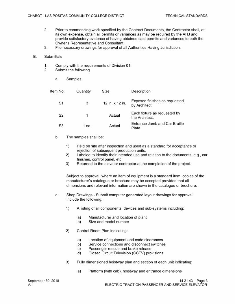
a. Samples
Item No. Quantity Size Description
S1 3 12 in. x 12 in. Exposed finishes as requested by Architect.
S2 1 Actual Each fixture as requested by the Architect.
S3 1 ea. Actual Entrance Jamb and Car Braille Plate.
b. The samples shall be:
1) Held on site after inspection and used as a standard for acceptance or rejection of subsequent production units.
2) Labeled to identify their intended use and relation to the documents, e.g., car finishes, control panel, etc.
3) Returned to the elevator contractor at the completion of the project.
Subject to approval, where an item of equipment is a standard item, copies of the manufacturer’s catalogue or brochure may be accepted provided that all dimensions and relevant information are shown in the catalogue or brochure.
c. Shop Drawings - Submit computer generated layout drawings for approval. Include the following:
1) A listing of all components, devices and sub-systems including:
a) Manufacturer and location of plantb) Size and model number
2) Control Room Plan indicating:
a) Location of equipment and code clearancesb) Service connections and disconnect switchesc) Passenger rescue and brake released) Closed Circuit Television (CCTV) provisions
3) Fully dimensioned hoistway plan and section of each unit indicating:
a) Platform (with cab), hoistway and entrance dimensions
CHABOT - LAS POSITAS COMMUNITY COLLEGE DISTRICT TECHNICAL STANDARDS
September 30, 2018 14 21 43 – Page 4V.1 ELECTRIC TRACTION PASSENGER AND SERVICE ELEVATOR
b) All running clearancesc) Location of fixturesd) Buffers, service ladders and pit reactionse) Location of insertsf) Rail Reactions
4) Entrance details5) Sill support detail6) Fixture details including hall lanterns, hall pushbutton stations, car operating
panel, etc.7) Wiring diagrams8) Insert diagrams9) Cab details including wall, ceiling, base, handrail, lighting, fixtures, front
return and transom plans and sections10) MRL criteria including:
a) Location of machine and governorb) Structural requirements and reactionsc) Clearancesd) Access requirements
3. Calculations
a. Rail loadsb. Pit and control room reactionsc. Heat emissions in control room and hoistwayd. Electrical loads including, accelerating and running currents. Include all auxiliary
loads.e. Submit design calculations identifying seismic design forces and support
capacities. Calculations shall be certified by a registered professional engineer.
C. Keys
1. Upon the initial acceptance of work specified by the Contract Documents on each unit, the Contractor shall deliver to the Owner, six (6) keys for each general key-operated device that is provided under these specifications in accordance with ASME A17.1, Part 8 standards as may be adopted and modified by the AHJ.
2. All other keying of access or operation of equipment shall be provided in accordance with ASME A17.1 Part 8 as may be adopted and modified by the AHJ.
D. Diagnostic Tools
1. Prior to seeking final acceptance of the project, the Contractor shall deliver to the Owner any specialized tools required to perform diagnostic evaluations, adjustments, and/or programming changes on any microprocessor-based control equipment installed by the Contractor. All such tools shall become the property of the Owner.
a. Owner’s diagnostic tools shall be configured to perform all levels of diagnostics, systems adjustment and software program changes which are available to the Contractor.
b. Owner’s diagnostic tools that require periodic re-calibration and/or re-initiation shall be performed by the Contractor at no additional cost to the Owner for a period equal to the term of the maintenance agreement from the date of final acceptance of the project.

CHABOT - LAS POSITAS COMMUNITY COLLEGE DISTRICT TECHNICAL STANDARDS
September 30, 2018 14 21 43 – Page 5V.1 ELECTRIC TRACTION PASSENGER AND SERVICE ELEVATOR
c. The Contractor shall provide a temporary replacement, at no additional cost to the Owner, during those intervals in which the Owner might find it necessary to surrender a diagnostic tool for re-calibration, re-initiation or repair.
2. Contractor shall deliver to the Owner, printed instructions, access codes, passwords or other proprietary information necessary to interface with the microprocessor-control equipment.
E. Service Support Requirements / Spare Parts
1. Printed Circuit Boards, Software Programs and Spare Parts
a. Prior to seeking final acceptance of the project as specified by the Contract Documents, the Contractor shall deliver to the Owner a spare replacement for each printed circuit board that is needed to fully operate any one (1) of the following:
1) Elevator and the group dispatch/supervisory controller where applicable:
a) Circuit boards shall be exact duplicates of those in use and shall be provided with “as installed” software programs.
b) Circuit boards shall be “run in” on the job site to demonstrate its ability to function in a normal manner.
c) All spare printed circuit boards shall become property of the Owner.
F. Wiring Diagrams, Operating Manuals and Maintenance Data
1. Comply with the requirements of Division 01.2. Deliver to the Owner, four (4) identical volumes of printed information organized into
neatly bound manuals prior to seeking final acceptance of the project. 3. The manuals shall also be submitted in electronic format on non-volatile media,
incorporating raw ‘CAD’ and/or Acrobat ‘PDF’ file formats.4. Manuals, as well as electronic copies, shall contain the following:
a. Step-by-step adjusting, programming and troubleshooting procedures that pertain to the solid-state microprocessor-control and motor drive equipment.
b. Passwords or identification codes required to gain access to each software program in order to perform diagnostics or program changes.
c. A composite listing of the individual settings chosen for variable software parameters stored in the software programs of both the motion and dispatch controllers.
d. Method of control and operation.
5. Provide four (4) sets of “AS INSTALLED” straight-line wiring diagrams in both hard and electronic format in accordance with the following requirements:
a. Displaying name and symbol of each relay, switch or other electrical component utilized including identification of each wiring terminal.
b. Electrical circuits depicted shall include all those which are hard wired in both the machine room and hoistway.
c. Supplemental wiring changes performed in the field shall be incorporated into the diagrams in order to accurately replicate the completed installation.
6. Furnish four (4) bound instructions and recommendations for maintenance, with special reference to lubrication and lubricants.

CHABOT - LAS POSITAS COMMUNITY COLLEGE DISTRICT TECHNICAL STANDARDS
September 30, 2018 14 21 43 – Page 6V.1 ELECTRIC TRACTION PASSENGER AND SERVICE ELEVATOR
7. Manuals or photographs showing controller repair parts with part numbers listed.
G. Patents
1. Patent licenses which may be required to perform work specified by the Contract Documents shall be obtained by the Contractor at its own expense.
2. The Contractor agrees to defend and save harmless the Owner, Consultant and agents, servants, and employees thereof from any liability resulting from the manufacture or use of any patented invention, process or article of appliance in performing work specified in the Contract Documents.
1.3 QUALITY ASSURANCE
A. Qualifications
1. The work shall be performed by a company specialized in the business of manufacturing, installing and servicing conveying systems of the type and character required by these specifications with a minimum of ten (10) years’ experience.
2. Prior written acceptance is required for manufacturers other than those listed, before quoting this project. Requests for acceptance will not be considered unless they are submitted before bid date and are accompanied by the following information:
a. List of five (5) similar installations having exact equipment being proposed for this project arranged to show name of project, system description and date of completed installation. The list shall include the names, position and resumes of the construction team and field supervisor of the installations.
b. Complete literature, performance and technical data describing the proposed equipment. Include the names, position and resumes of the proposed construction team and field supervisor.
c. List of ten (10) service accounts by building name, building manager or owner, including phone numbers.
d. Location of closest service office from which conveying system will be maintained.e. Location of closest parts inventory for this installation.f. List of the names, positions and resumes of the construction teams and field
supervisor for the installation.
B. Structural, Mechanical and Electrical Design Parameters
1. The mechanical and electrical systems and the building structure have been designed for the following design loads:
a. Structural Loads:
1) The pit, machine room and rail loads are shown on the drawings.
2. Power supply: 460-3-60 (EE to verify) 3. Electrical Loads:
a. Passenger Elevator
1) 10 HP2) 13 A. FLR (Full Load Running)3) 33 A. FLA (Full Load Acceleration)

CHABOT - LAS POSITAS COMMUNITY COLLEGE DISTRICT TECHNICAL STANDARDS
September 30, 2018 14 21 43 – Page 7V.1 ELECTRIC TRACTION PASSENGER AND SERVICE ELEVATOR
b. Service Elevator
1) 10 HP2) 13 A. FLR (Full Load Running)3) 33 A. FLA (Full Load Acceleration)
4. Heat Release:
a. Passenger Elevator: 5000b. Service Elevator: 5000
5. Submit a written statement with the bid that the above design loads and the clearance requirements shown on the Architectural drawings are acceptable for the proposed equipment. If not, specifically state the design variances.
a. After the award, if the type of equipment provided requires structure, mechanical and electrical system changes and/or revisions, the Elevator Contractor shall be responsible for all additional design and construction costs.
1) Electrical equipment, motors, controllers, etc., installed under this contract shall have necessary CSA/US or UL listing as may be required by the AHJ. Equipment shall be labeled or tagged accordingly.
1.4 DELIVERY / STORAGE / HANDLING / COORDINATION
A. Delivery and Storage of Material and Tools
1. Comply with the requirements of Division 01.2. Delivery, Storage and Handling:
a. Deliver materials to the site ready for use in the accepted manufacturer's original and unopened containers and packaging, bearing labels as to type of material, brand name and manufacturer's name. Delivered materials shall be identical to accepted samples.
b. Store materials under cover in a dry and clean location, off the ground.c. Remove delivered materials which are damaged or otherwise not suitable for
installation from the job site and replace with acceptable materials.
3. The Owner shall bear no responsibility for the materials, equipment or tools of the Contractor and shall not be liable for any loss thereof or damage thereto.
4. The Contractor shall confine storage of materials on the job site to the limits and locations designated by the Owner and shall not unnecessarily encumber the premises or overload any portion with materials to a greater extent than the structural design load of the Facility.
B. Work with Other Trades / Coordination
1. Coordinate installation of sleeves, block outs, equipment with integral anchors, and other items that are embedded in concrete or masonry for the applicable equipment. Furnish templates, sleeves, equipment with integral anchors, and installation instructions and deliver to Project site in time for installation.
2. Coordinate sequence of installation with other work to avoid delaying the Work.3. Coordinate locations and dimensions of other work relating to the equipment scheduled
for installation including pit ladders, sumps, and floor drains in pits; entrance subsills;

CHABOT - LAS POSITAS COMMUNITY COLLEGE DISTRICT TECHNICAL STANDARDS
September 30, 2018 14 21 43 – Page 8V.1 ELECTRIC TRACTION PASSENGER AND SERVICE ELEVATOR
machine beams; and electrical service, electrical outlets, lights, and switches in pits and machine rooms, secondary levels, overhead sheave rooms and hoistways as it relates to the specific equipment.
4. The Contractor shall also include all charges connected with:
a. Testing of the unit(s) for acceptance by the AHJ.b. Maintenance required for temporary service.
5. All equipment shall be restored to a "like new" condition at the Contractor's expense prior to acceptance of the work by the Construction Manager.
1.5 WARRANTY / MAINTENANCE SERVICES
A. Contract Close-Out, Guarantee and Warranties
1. Comply with the requirements of Division 01.2. Guarantee and Warranties:
a. Warrant the equipment installed under these specifications against defects in material and quality of installation and correct any defects not due to ordinary wear and tear or improper use of car which may develop within one year from the date each unit is completed and placed in permanent operation and accepted by the Owner.
b. This warrantee shall be written and issued at the completion of each unit prior to final payment.
B. Maintenance
1. Interim Maintenance: Provide full protective maintenance on the units that are completed and accepted by the AHJ and that may be put in service prior to the overall project completion. The maintenance service shall be as hereinafter specified under the Full Protective Maintenance Service in “3” below and include all code mandated safety and local law tests and inspections that may come due while on this service.
a. The price quoted shall be on a per unit per month basis.
2. Warranty Maintenance: Provide full protective maintenance on the specified equipment for a period of twelve (12) months from the date of final acceptance of the entire installation as specified under the Full Protective Maintenance Service in “3” below.
a. The price for this service shall be included in the base price or as otherwise specified in the contract documents.
3. Full Protective Maintenance Service: Submit a separate price for a Full Protective Maintenance Service for the specified units based on a five (5) year contract. The price shall be submitted on the company's own form but shall include all requirements as specified hereinafter. Note: All maintenance shall comply with Part 8 of the ASME A17.1 Code and modified or amended by the Authority Having Jurisdiction.
a. Maintenance work shall be performed by trained certified/qualified personnel directly employed and supervised by the service contractor.
b. Perform scheduled maintenance work and repairs during the regular working hours of regular working days of the trade. All work shall be coordinated with the Building Manager.

CHABOT - LAS POSITAS COMMUNITY COLLEGE DISTRICT TECHNICAL STANDARDS
September 30, 2018 14 21 43 – Page 9V.1 ELECTRIC TRACTION PASSENGER AND SERVICE ELEVATOR
4. Provide emergency callback service and repair twenty-four (24) hours a day, seven (7) days a week, including holidays, between regular examinations at no extra cost to the Owner. The response time during working hours shall not exceed one (1) hour. Perform emergency repairs within four (4) hours to restore the equipment to operating order. The following conditions will require emergency callback services for elevators:
a. Passenger entrapment.b. Failure or malfunction of control system.c. Shutdown of any elevator.
5. Maintenance shall include monthly examination, adjustment, lubrication, repair or replacement of electrical and mechanical parts of all equipment and apparatus.
6. The maintenance services shall also cover relamping of machine room and pit lighting fixtures, signal and operating fixtures, communication system, cab ventilation system, monitoring and control panels. The disconnect means, fuses, car enclosures, car doors and hoistway entrances are excluded. Repair equipment whenever required and use only genuine standard parts produced and manufactured for equipment concerned.
a. Include a minimum of three (3) hours of monthly labor per unit for the specified scheduled preventive maintenance service.
b. The performance of mandated inspections and tests of the equipment, as required by the AHJ, shall be included in this agreement.
1) Where required by the AHJ, witnessing shall be performed by a third party licensed agency hired directly by the Owner.
2) Where testing is required to be performed after normal business hours, Contractor shall invoice the after-hours work at the premium portion of the hourly billing rate only.
c. Provide monthly firefighter and semi-annual emergency power tests and inspections as required by Code. There will be two (2) emergency power tests per year which shall be conducted after work hours at no extra cost to the Owner.
d. One (1) month prior to the warranty expiration period, perform a Performance and Maintenance survey of all devices covered under the agreement and submit a report listing the recorded performance data, the emergency call-back services rendered during the year, and recommendations to further improve reliability and performance.
1) When requested, provide a recording of each car's acceleration, deceleration and jerk rates along with a 3-day history of average corridor call wait times from 7 a.m. to 6 p.m. as recorded on a specified Tuesday, Wednesday and Thursday.
2) Provide and document all Category 1 Periodic Tests.
e. During every scheduled maintenance visit, make sure the machine room and pit areas are clean.
1) Paint the machine room floor and machine room equipment every three (3) years.
f. Adjust controls and maintain the equipment to meet the performance requirements as hereinafter specified.
g. If overtime repairs and maintenance services are requested and pre-approved by the Owner, the Contractor shall pay for the regular labor portion, and the Owner will cover the premium portion of the labor only.
CHABOT - LAS POSITAS COMMUNITY COLLEGE DISTRICT TECHNICAL STANDARDS
September 30, 2018 14 21 43 – Page 10V.1 ELECTRIC TRACTION PASSENGER AND SERVICE ELEVATOR
h. Keep permanent record of inspections, maintenance services including lubrication procedures, emergency call-back services, repairs and replacements.
i. Maintain a complete set of updated wiring diagrams and schematic control diagrams in the machine room and provide the Owner with an additional record set.
7. Supply all necessary lubricants, cleaning materials and repair parts required to keep the system in good working order during maintenance periods.
8. Maintain an adequate stock of spare parts for maintenance or repair work and minor callback service repairs within the confines of the building in areas designated and assigned by the Owner. Maintain a catalog of spare parts available on site.
9. Additional parts of other equipment required for maintenance and repair of the systems may be stored at the Contractor's facilities with the understanding delivery of same for emergency procedures must be made within two (2) hours to the job site.
10. Other materials and equipment normally not stocked by the Trade Contractor locally must be available within twenty-four (24) hours for delivery to the job site from remote facilities and/or Supplier Contractors responsible to the Contractor for stocking the materials or equipment.
11. If the requirements for stockade of parts as defined herein are not met on any item, immediately notify the Owner in writing as to the circumstances and provide a confirmed delivery date for the required materials and equipment.
12. Should it become necessary to work on the equipment, proper safety barricades shall be erected to protect people from all hazards.
13. If for any reason (such as strike), it is mutually agreed to temporarily reduce the level of maintenance, the monthly amount of the maintenance contract shall be reduced to reflect the reduction in maintenance services.
14. Should the Owner request that the maintenance Contractor perform any work on the equipment of this Contract, but not included in the terms of the Contract, then payment for such work shall be based on the rates included in the Contract for time and material.
15. Thirty (30) days before the annual renewal of this agreement, adjust monthly maintenance price as follows:
a. Eighty percent (80 percent) of the current maintenance price based on current straight-time hourly rate for a mechanic.
b. Twenty percent (20 percent) of the current maintenance price based on the established difference in the “Producer Commodity Prices for Wholesale Metals and Metal Products Index”.
c. Notwithstanding anything to the contrary, the maximum annual increase shall not be more than three percent (3.0 percent) of the total contracted payment for the preceding contract year.
16. Cancellation: The Owner has the right to cancel this contract on 30 days notice.17. Obtain the following minimum insurance coverage:
a. Commercial General Liability Insurance on an Occurrence basis including:
1) Bodily Injury, Property Damage including Personal Injury and death.2) “Per Project” endorsement.3) Broad form property damage liability.4) Blanket Contractual Liability including contractual liability assumed by this
contract.5) Independent Contractors Protective Liability coverage. The minimum limit
for Comprehensive Liability insurance coverage shall be:

CHABOT - LAS POSITAS COMMUNITY COLLEGE DISTRICT TECHNICAL STANDARDS
September 30, 2018 14 21 43 – Page 11V.1 ELECTRIC TRACTION PASSENGER AND SERVICE ELEVATOR
a) Each Occurrence: $1,000,000General Aggregate: $2,000,000including “Per Project”endorsement Products andCompleted Operations Aggregate: $1,000,000
b) Excess liability limits of not less than:Each Occurrence: $4,000,000Coverage to follow form of underlying policies.
6) Worker’s Compensation Insurance – In accordance with the statutory limits.7) Employer’s Liability Insurance – With a minimum limit of not less than:
a) Bodily Injury by Accident: $1,000,000 each accidentb) Bodily Injury by Disease: $1,000,000 each employeec) Bodily Injury by Disease: $1,000,000 policy limit
8) Statutory State Disability Benefits Insurance covering all persons employed by the Contractor in connection with this contract.
b. The foregoing insurance policies shall be primary to any other insurance which may be carried by the Owner or Owner’s Agent and shall name the Owner, the Owner’s Agent and the Consultant as additional insured with a specific policy endorsement as follows:
Brookfield Properties Gensler Architects VDA (Van Deusen & Associates)
c. Certificates of Insurance evidencing such coverage shall be filed with the Owner’s Agent prior to the commencement of the contract and all renewals of insurance certificates shall be furnished prior to the expiration of any coverage herein.
d. The policies shall contain a provision giving Owner and Owner’s Agent thirty (30) days, or any longer period prescribed by California Insurance Law, prior written notice of any change or cancellation of such insurance, in the event of cancellation of Non Payment of Premium, in which ten (10) day notice will be provided. This notice shall be included on the Certificate of Insurance.
e. All insurance must be with a licensed and admitted insurance carrier maintaining no less than an A.M. Best’s rating of “A” or better, shall be size VII, and shall be subject to acceptance by Owner’s Agent in its sole discretion.
f. The Contractor agrees that the required insurance is not intended to limit the Contractor’s liability in the event that Contractor is deemed to be negligent in causing bodily injury or property damage during the course of its operation.
g. The Contractor shall, at its own expense, maintain physical damage insurance in the amounts and against the perils desired by the Contractor on all property of any kind owned or rented by the Contractor. The Contractor hereby waives its rights of recovery against the owner for any damage or loss to property of any kind which is owned or rented by Contractor or for which the Contractor is liable.
h. The Purchaser/Owner may have the Contractor's work and systems' performance operation checked monthly to ensure the Contractor is performing in accordance with this Contract. If the work requirements are not maintained, the Purchaser/Owner will retain the monthly payment to the Contractor until the Consultant verifies that the work and/or operating performance is back to standard. If three (3) consecutive months of substandard maintenance is noted, the Owner has the right to immediately cancel the Contract without notice to the Contractor.

CHABOT - LAS POSITAS COMMUNITY COLLEGE DISTRICT TECHNICAL STANDARDS
September 30, 2018 14 21 43 – Page 12V.1 ELECTRIC TRACTION PASSENGER AND SERVICE ELEVATOR
1) The Consultant, Purchaser and/or Owner's Designee may withhold approval for payment on any request to such extent as may be necessary to protect the Owner from loss on account of:
a) Negligence on the part of the Contractor to execute the work properly or failure to perform any provisions of the contract, The Owner, after three (3) days written notice to the Contractor, may, without prejudice to any other remedy make good such deficiencies and may deduct the cost of the contract.
b) Claims filed or reasonable evidence indicating probable filing of claims due to the Contractor's failure to perform.
c) Failure of Contractor to make payments properly to subcontractor for material and labor used to fulfill contractual requirements.
d) Damage to the building as a result of work performed or another subcontractor's failure to perform.
i. Contractor shall notify Purchaser and Consultant in writing regarding any necessary services, coverage or times which may have been omitted from the maintenance contract specifications and any irregularities, discrepancies or duplications that could affect the full comprehensive intent of the agreement.
1) Any duplication of work or coverage is specified as a means of demonstrating the contract requirements, but such duplication, if any, is not intended to expand coverage or increase requirements for such work or services and such duplication shall not increase costs or provide justification for extra or additional charge to the Purchaser.
1.6 ALTERNATES / ALLOWANCES
A. Alternates
1. Value Engineering Alternate
a. It is understood that the base specification reflects minimum standards. The above Value Engineering Alternate allows individual contractors to suggest special performance criteria which may be of interest to the Owner and may reflect a degree of quality above the requirements of the base specification.
b. Voluntary alternate prices may be acceptable as a deviation from, not a substitution for, the basis of bid work of this bid package.
c. In order to submit a voluntary alternate, the following must be provided at the time of the bid.
1) A complete bid reflecting the requirements of the base specification.2) All alternates must be accompanied with pertinent data, technical
documentation and reference/installation for review.3) Along with the pricing for voluntary alternates submit the maintenance prices
for each.
2. Allowances
a. Passenger elevator cab allowance $40,000 per elevator
CHABOT - LAS POSITAS COMMUNITY COLLEGE DISTRICT TECHNICAL STANDARDS
September 30, 2018 14 21 43 – Page 13V.1 ELECTRIC TRACTION PASSENGER AND SERVICE ELEVATOR
PART 2 - PRODUCTS
2.1 GENERAL DESCRIPTION
A. Passenger Elevator
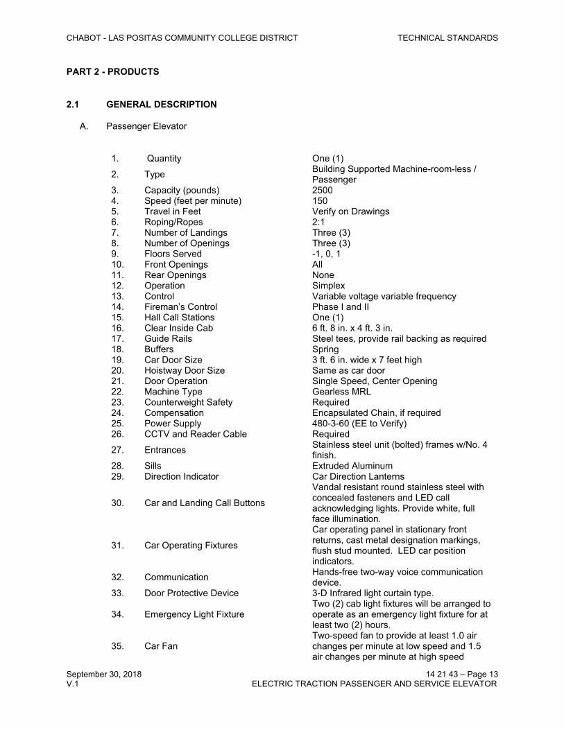
1. Quantity One (1)
2. Type Building Supported Machine-room-less / Passenger
3. Capacity (pounds) 25004. Speed (feet per minute) 1505. Travel in Feet Verify on Drawings6. Roping/Ropes 2:17. Number of Landings Three (3)8. Number of Openings Three (3)9. Floors Served -1, 0, 110. Front Openings All 11. Rear Openings None12. Operation Simplex13. Control Variable voltage variable frequency14. Fireman’s Control Phase I and II15. Hall Call Stations One (1)16. Clear Inside Cab 6 ft. 8 in. x 4 ft. 3 in.17. Guide Rails Steel tees, provide rail backing as required18. Buffers Spring19. Car Door Size 3 ft. 6 in. wide x 7 feet high20. Hoistway Door Size Same as car door21. Door Operation Single Speed, Center Opening22. Machine Type Gearless MRL23. Counterweight Safety Required24. Compensation Encapsulated Chain, if required25. Power Supply 480-3-60 (EE to Verify)26. CCTV and Reader Cable Required
27. Entrances Stainless steel unit (bolted) frames w/No. 4 finish.
28. Sills Extruded Aluminum29. Direction Indicator Car Direction Lanterns
30. Car and Landing Call Buttons
Vandal resistant round stainless steel with concealed fasteners and LED call acknowledging lights. Provide white, full face illumination.
31. Car Operating Fixtures
Car operating panel in stationary front returns, cast metal designation markings, flush stud mounted. LED car position indicators.
32. Communication Hands-free two-way voice communication device.
33. Door Protective Device 3-D Infrared light curtain type.
34. Emergency Light FixtureTwo (2) cab light fixtures will be arranged to operate as an emergency light fixture for at least two (2) hours.
35. Car FanTwo-speed fan to provide at least 1.0 air changes per minute at low speed and 1.5 air changes per minute at high speed

CHABOT - LAS POSITAS COMMUNITY COLLEGE DISTRICT TECHNICAL STANDARDS
September 30, 2018 14 21 43 – Page 14V.1 ELECTRIC TRACTION PASSENGER AND SERVICE ELEVATOR
36. Cab Enclosure As specified and shown on drawings.

CHABOT - LAS POSITAS COMMUNITY COLLEGE DISTRICT TECHNICAL STANDARDS
September 30, 2018 14 21 43 – Page 15V.1 ELECTRIC TRACTION PASSENGER AND SERVICE ELEVATOR
B. Service Elevator
1. Quantity One (1)
2. Type Building Supported Machine-room-less / Passenger
3. Capacity (lbs) 25004. Speed (fpm) 1505. Travel in Feet Verify on Drawings6. Roping/Ropes 2:17. Number of Landings Two (2)8. Number of Openings Two (2)9. Front Openings One (1)10. Rear Openings One (1)11. Floors served 0 and 112. Operation Simplex13. Control Variable voltage variable frequency14. Fireman’s Control Phase I and II15. Number of Hall Stations One (1)16. Clear Inside Cab 6 ft.8 in. x 4 ft. 3 in.17. Guide Rails Steel tees, provide rail backing as required18. Buffers Spring19. Car Door Size 3 ft. 6 in. wide x 7 feet high20. Hoistway Door Size Same as car door21. Door Operation Single Speed, Center Opening22. Machine Type Gearless MRL23. Counterweight Safety Required24. Compensation Encapsulated Chain, if required25. Power Supply 480-3-6026. CCTV and Card Reader By Others27. CCTV and Reader Cable Required28. PA Speaker By Others29. PA Cable Required
30. Entrances Stainless steel unit (bolted) frames w/No. 4 finish.
31. Sills Extruded Aluminum
32. Car Operating Fixtures
Car operating panel in stationary front returns, cast metal designation markings, flush stud mounted. LED car position indicators.
33. Direction Indicators Car Direction Lanterns34. Communication Hands-free communication device 35. Door Protective Device 3-D Infrared light curtain type.
36. Emergency Light FixtureTwo (2) cab light fixtures will be arranged to operate as an emergency light fixture for at least two (2) hours.
37. Car FanTwo-speed fan to provide at least 1.0 air changes per minute at low speed and 1.5 air changes per minute at high speed
38. Cab Enclosure As specified and shown on drawings.
2.2 MANUFACTURERS
A. Pre-Approved Equipment Manufacturers

CHABOT - LAS POSITAS COMMUNITY COLLEGE DISTRICT TECHNICAL STANDARDS
September 30, 2018 14 21 43 – Page 16V.1 ELECTRIC TRACTION PASSENGER AND SERVICE ELEVATOR
1. In addition to Original Equipment Manufacturers, the following manufacturer’s equipment and materials have been pre-approved for use on this project.
2. Other manufacturers/products not specifically mentioned below shall be considered for approval on an individual basis.
a. Controls: MCE, SmartRiseb. Tracks, Hangers, Interlocks and Door Operators - G.A.L., ECI.c. Fixtures – EPCO Survivor Plus CA or equal.d. Door Protective Device - Janus, Panachrome Plus or equal. e. Cabs and Entrances - EDI/ECI, National Cab and Door, Tyler, Velis, Gunderlin,
Forms and Surfaces, Eklunds, EMCO, Columbia Elevator Products, Sterling, CityLift.
f. Machines - Hollister-Whitney, Titan, Imperial, Torin.g. Motors - Imperial Electric, General Electric, Baldor, Reuland Electric.h. VVVF Power Drives - Mitsubishi, MagneTek, Yaskawa, TorqMax.i. VVVF Emergency Power Systems – MCE, Reynolds and Reynolds Electronics.j. Guide Rails - Savera, Monteferro.k. Electrical Traveling Cables – Draka, James Monroel. Guide Shoes/Rollers – ELSCO, G.A.L.m. Wire Ropes - Paulsen, Bethlehem, Wayland, Draka.n. Intercommunications/Telephones - Webb Electronics, K-Tec, Ring, Wurtec, Janus,
approved equal.
3. Original Equipment Manufacturers may substitute their own branded equipment subject to the following:
a. All requirements of the specifications are met regarding performance, appearance, serviceability and support.
b. A full stock of all regular and critical replacement parts required for this project are maintained at a facility within fifty (50) miles of the project site.
1) Any parts not stocked at the above referenced facility shall be identified with the location of the nearest source and shall be available for next-day delivery upon demand.
c. All parts and software shall be made available for purchase to a qualified elevator maintenance firm within one-business day delivery without direct Owner involvement.
1) Provide details of parts supply facility and a list of current parts pricing for all major components required for the installation.
d. All specialized tools, equipment, software, and passwords, required to maintain, repair, adjust the operation, and perform code mandated tests/inspections are provided to the Owner as part of the base installation.
1) Updates to these items shall be available via the parts supply facility referenced above.
e. Technical support of the product(s) shall be available to the Owner’s elevator service provider.
2.3 CONTROL FEATURES / OPERATION
CHABOT - LAS POSITAS COMMUNITY COLLEGE DISTRICT TECHNICAL STANDARDS
September 30, 2018 14 21 43 – Page 17V.1 ELECTRIC TRACTION PASSENGER AND SERVICE ELEVATOR
A. Motion Control
1. Smooth step-less acceleration and deceleration of the elevator car shall be provided in either direction of travel during both single and multiple floor runs.
2. Use digital logic to calculate optimum acceleration and deceleration patterns during each run.
a. The amplitude of acceleration and deceleration shall not exceed 2.6 - 2.8 ft./sec2
for MRL traction, and 3.5 - 4 ft./sec2 for gearless traction elevators. b. The maximum jerk rate shall be 1.5 to 2.0 times the acceleration and deceleration.c. The maximum velocity which the elevator achieves in either direction of travel
while operating under load conditions that vary between empty car and full rated load shall be within ± 3 percent of the rated speed.
3. Floor leveling accuracy of ± ¼ inch as measured between the car entrance threshold and the landing sill on any given floor shall be provided.
a. This accuracy standard shall be maintained under varying load conditions and without need for releveling corrections caused by overshooting or stopping short of the floor.
4. Elapsed flight time during a typical elevator one floor run shall not exceed values as further specified.
a. Timing, as measured between the moment door closing operations begin and when the doors are 3/4 open at the next adjacent floor, shall remain consistent under varying load conditions in either direction of travel.
B. Simplex Selective Collective Operation
1. Provide simplex selective collective operation from a riser of hall push button stations.2. The registration of one or more car calls shall dispatch the car to the selected floors.
a. The car shall also respond to registered hall calls in the same direction of travel. b. Car and hall calls shall be canceled when answered.
3. Stops in response to calls that are registered in either the car or hall push button stations shall occur in the natural order of progression in which the floors are encountered, depending on the direction of car travel, and irrespective of the order in which calls are registered.
4. When the car has responded to the highest or lowest call, and calls are registered for the opposite direction, the car shall reverse direction automatically and respond to those registered calls.
5. When the car arrives at its last stop and reverses direction of travel, all previously registered car calls shall be automatically cancelled.
6. When the car arrives at a landing where both up and down hall calls are registered, it will answer the call in the direction of travel.
a. After a pre-determined delay, if no car call is registered, the car shall respond to calls registered for the opposite direction. Car doors shall close immediately, re-open and respond to the call for the opposite direction.
b. Hall lantern operation shall always correspond to direction of service.
7. When an empty car reverses direction at a landing with no hall calls, the doors shall not open and the hall lantern shall not operate.

CHABOT - LAS POSITAS COMMUNITY COLLEGE DISTRICT TECHNICAL STANDARDS
September 30, 2018 14 21 43 – Page 18V.1 ELECTRIC TRACTION PASSENGER AND SERVICE ELEVATOR
8. If the car has no car calls registered and arrives at a floor where both up and down hall calls have been registered, the car shall respond to the hall call corresponding to the last direction of car travel. If, after making its stop, a car call is not registered and no other hall calls exist ahead of the car corresponding to its original direction of travel, the doors shall close and immediately reopen in response to the hall call for the opposite direction.
9. The car shall maintain its original direction at each stop until the doors are fully closed to permit a passenger to register a car call before the car reverses its direction of travel.
C. Independent Service Operation
1. The car operating station shall be equipped with a key-operated switch labeled “IND SER”.
2. Locate the switch in the locked service compartment.3. When placed in the “on” position the following shall occur:
a. Group elevator - the elevator shall bypass corridor calls and travel directly to any floor chosen by registration of a car call. Hall calls shall remain registered for service by another elevator in the group.
4. During Independent Service Operation, the elevator doors shall remain open at any landing until the door close or a car call push button is pressed and maintained until the doors are fully closed.
5. If more than one (1) car call is registered, all registered car calls shall extinguish when the elevator stops in response to the first call.
6. Fire Emergency Recall shall automatically override Independent Service Operation and engage Phase I - Fire Emergency Recall Operation following a period of approximately forty-five (45) seconds.
D. Inspection Service Operation
1. Provide a key operated switch in locked service panel that, when turned to the ‘ON’ position, shall cause the elevator to be removed from service and placed in Inspection Service Operation.
2. Limited operation of the car shall be provided through pressing the highest or lowest car call push buttons (if up and down buttons are not provided) in the main car operating panel only.
3. The car shall move at a speed not to exceed 150 feet per minute (0.75 meters per second) as per code with both the hall and car door panels in the closed and locked position.
4. The Inspection Service switch shall be keyed differently than other typical keys used in the operation of the elevator. Keying shall be in accordance with Security Group Classifications as required by applicable code.
5. The top of the elevator car shall be equipped with a control for limited operation of the car during repairs, maintenance and inspection conducted in the hoistway. The transfer of control to the top of car operating device shall cause that device to be the sole means of control for the elevator.
a. Visual and audible indication shall be provided on the top of the car when Firefighters’ Emergency Operation is initiated.
6. Power door operating equipment shall be rendered inoperative while the car is being operated in the Inspection Service mode with the exception of power closing of the door. The control system shall maintain closing power on the door while the elevator is moving under Inspection Service Operation.
7. The in-car Inspection Service switch shall be rendered ineffective when the top of car inspection control is activated.
CHABOT - LAS POSITAS COMMUNITY COLLEGE DISTRICT TECHNICAL STANDARDS
September 30, 2018 14 21 43 – Page 19V.1 ELECTRIC TRACTION PASSENGER AND SERVICE ELEVATOR
8. Machine Room Inspection Operation and Inspection Operation with open door circuits shall be provided in accordance with A17.1 Safety Code, as modified and adopted, where required or allowed by the AHJ.
E. Hoistway Access Operation
1. Provisions shall be made to allow access to the hoistway through the use of hoistway access switches.
2. Operating the access switch shall permit the car to move at a speed not to exceed 150 feet per minute (0.75 meters per second) as per code with the hall and car doors in the open position to obtain access to the top of the car or climb-in pit.
3. The car shall automatically stop motion when the car top is level with the hoistway door sill for access to top of car.
4. The access key switch(es) shall be keyed differently than other typical keys used in the operation of the elevator. Keying shall be in accordance with Security Group Classifications as required by applicable code.
5. Access operation shall be disabled when top of car inspection operation is in effect.
F. Firefighters’ Emergency Operation
1. Firefighters Service Operation and devices shall meet applicable code requirements of the AHJ.
2. Contractor shall be responsible for compliance in all aspects of Firefighters Service including, but not limited to the mode of operation, initiation of operation, operating control and signaling devices as well as fixture engraving including operating instructions applicable to and where required by the AHJ.
G. Emergency Power Operation / Sequential Recall
1. Provisions shall be included in the elevator control system whereby all affected elevators shall automatically return to the fire recall designated landing in progressive numerical sequence at normal speed, unless otherwise specified, immediately after transferring to the emergency power system.
a. Car and corridor calls shall become inoperative and all previously registered calls shall be canceled.
b. As each car arrives at the designated landing, it shall park out of service with its door(s) in the open position.
2. An illuminated signal marked “ELEVATOR EMERGENCY POWER” shall be provided in the elevator lobby at the designated level to indicate that the normal power supply has failed and the emergency power is in effect.
3. In the event an elevator fails to respond to a recall command within forty-five (45) seconds under Emergency Power Operation, that car shall be bypassed and the next car in the sequence shall be recalled.
4. Upon completion of the recall process, one or more elevators shall be automatically selected to run on the emergency power source. Where more than one (1) elevator can operate on emergency power simultaneously, the Contractor shall coordinate the maximum number of elevators with Owner.
5. Coordinate the sequence of automatic recall operation of the elevators with the Owner.6. Interlock all elevators to allow to operate the maximum number of elevators at a time.7. An emergency power control panel for all elevators shall be provided where directed by
the Owner containing an indicator light per elevator that becomes illuminated whenever a transfer to emergency power takes place.

CHABOT - LAS POSITAS COMMUNITY COLLEGE DISTRICT TECHNICAL STANDARDS
September 30, 2018 14 21 43 – Page 20V.1 ELECTRIC TRACTION PASSENGER AND SERVICE ELEVATOR
a. Means shall be provided on or adjacent to the control panel to indicate that the elevator is at the designated level with the doors in the open position.
8. A key-operated override switch and a manual selector switch with a position indicator for each elevator shall be provided in the emergency control panel.
a. Activating the key-operated override switch while on emergency power shall cancel the previously mentioned automatic recall sequence and allow positioning of the manual selector switch to select a car for operation.
9. Prior to return to normal power, the building ATS shall provide a “pre-transfer” signal to the elevator equipment that will initiate the landing of elevators prior to transfer from emergency power to normal power.
a. Timer of the pre-transfer signal shall be adjustable from 15 to 30 seconds.
10. The following additional requirements apply:
a. Firefighters’ Service Operation will remain active at all times during emergency power operation but limited to the elevator selected to be in operation.
b. All car lighting will remain active with car lighting on separate emergency power feeders in addition to battery back-up.
c. Communications will remain active at all times via emergency power feeders in addition to battery back-up.
d. Remote monitoring will be active from each group dispatcher for selected elevators using an uninterrupted power supply (UPS) to maintain the central processing unit during power transfers.
e. Position indicator for each elevator will be active in the selected elevator and security room (where applicable), as well as lobby display panels.
11. Testing of elevators under emergency power shall be accomplished with the building ATS providing necessary “pre-transfer” signals to the elevator control apparatus.
a. Prior to testing, the building ATS shall provide a “pre-transfer” signal to initiate the landing of the elevators prior to the transfer from normal to emergency power.
b. After testing, the building ATS shall provide a “pre-transfer” signal to initiate the landing of the elevators prior to the transfer from emergency to normal power.
H. Elevator Safety Requirements for Seismic Zone 4
1. Guarding of equipment, machine supports, guide rail systems, the design of counterweight car frame and platform, safeties and signaling devices shall meet the requirements of ASME A17.1 as may be modified by the AHJ.
2. Guide rails, guide rail supports and their fastenings shall meet requirements for the seismic zone.
I. Passenger Rescue Feature
1. Provide a device in the control room to move the elevator car to a floor landing in the event of controller or power failure.
a. This device must be speed controlled to prevent an overspeed condition.b. A line of sight must be provided between the Passenger Rescue Feature device
and the elevator car.
CHABOT - LAS POSITAS COMMUNITY COLLEGE DISTRICT TECHNICAL STANDARDS
September 30, 2018 14 21 43 – Page 21V.1 ELECTRIC TRACTION PASSENGER AND SERVICE ELEVATOR
1) Coordinate line of sight requirements with the control room requirements.
2. Provide a manual brake release lever attached to the control cabinet for rescue of passengers.
a. A visual display shall be provided with the control cabinet, which indicates car position, speed and directions.
J. Door Operation
1. Car and hoistway doors shall be arranged to operate in unison without excessive noise or slamming in either direction of travel.
a. Door opening speeds of two (2) feet per second shall be provided in conjunction with closing speeds of 1.0 feet per second in accordance with governing code.
b. Door operation shall commence as the car stops level at the floor and the machine brake is applied. Pre-door opening shall not be permitted.
2. Where the hoistway door and the car door are mechanically coupled, the kinetic energy of the closing door system shall be based upon the sum of the hoistway and the car door weights, as well as all parts rigidly connected thereto, including the rotational inertia effects of the door operator and the connecting transmission to the door panels.
3. The force necessary to prevent closing of the car and hoistway door from rest shall not exceed 30 lbf. This force shall be measured on the leading edge of the door with the door at any point between one third and two thirds of its travel.
4. Door open and door close time shall be measured between the moment car door operation in either direction begins and the instant at which that cycle is completed.
5. When responding to either a car or corridor call, the amount of time that the elevator door remains stationary in the open position shall be adjustable up to sixty (60) seconds.
a. Door open dwell time for a corridor call shall be separate of that for a car call, and in both cases, dwell time shall be canceled whenever the car door protection device is momentarily interrupted by passenger transfers, followed by a reduced door open dwell time of approximately one (1) second (adjustable) after the door protection device is cleared of obstructions.
6. The interruption of one or more infrared light beams (dual or multi-beam non-contact) during the close cycle shall cause the immediate reversing of the doors to the full open position.
7. The door closing cycle shall be arranged so that, in the event the door protective devices become continually obstructed after the normal door open dwell time has expired, and following a time interval of approximately thirty (30) seconds (adjustable), a warning tone shall sound and the door closing cycle shall commence at reduced speed and torque per applicable Code requirements.
8. Each car operating station shall be provided with a “door open” and “door close” push button.
a. Pressure on the “door open” button shall cause doors in the full open position to remain so and doors engaged in the close cycle to reverse direction and assume the full open position so long as pressure remains applied to the button.
b. The “door open” buttons shall also control the open cycle during Phase II - Emergency In-car Operation.
c. The “door close” push button shall function on Independent Service, Attendant Service and Phase II - Emergency In-car Operation as well as during normal automatic operations.
CHABOT - LAS POSITAS COMMUNITY COLLEGE DISTRICT TECHNICAL STANDARDS
September 30, 2018 14 21 43 – Page 22V.1 ELECTRIC TRACTION PASSENGER AND SERVICE ELEVATOR
9. Repeated attempts by the power door operator to open or close the door at any landing shall be monitored by the control system.
a. In the event the door fails to cycle properly after a preset (adjustable) number of attempts, the car shall either travel to the next stop or remove itself from service, depending upon whether the malfunction is in the open or close cycle.
10. Each hoistway door shall be provided with an automatic self-closing mechanism arranged so that the door shall close and lock if the car should leave the landing while the hoistway door is unlocked.
11. Car doors shall be arranged to prevent their being manually opened from inside the car unless the elevator is positioned within a floor landing zone.
2.4 CONTROL ROOM EQUIPMENT
A. Controller / Dispatcher
1. The elevators shall have microprocessor based controller/dispatchers.2. Digital logic shall calculate optimum acceleration, deceleration and velocity patterns for
the car to follow during each run. 3. Closed-loop distance and velocity feedback shall monitor the actual performance of the
elevator car with the desired speed profile. 4. System operating software shall be stored in non-volatile memory.5. Elevator control relays, contactors, switches, capacitors, resistors, fuses, circuit breakers,
overload relays, power supplies, electronic circuit boards, microprocessors, static motor drive units, wiring terminal blocks and related components shall be totally enclosed inside a free-standing metal cabinet with hinged access doors.
a. Provide natural or mechanical ventilation for the controller cabinets.b. Equip the vent openings and exhaust fans with filters.
6. Mount equipment to moisture-resistant, noncombustible panels supported from the steel frame.
7. Provide "noise filter" between hoistway wiring and controller/dispatchers to eliminate interference.
8. Optically isolate communication cables between components.9. Wiring: Wiring on the units, whether factory or field wiring, shall be done in neat order,
and all connections shall be made to studs and/or terminals by means of grommets, solderless lugs or similar connections. All wiring shall be copper.
10. Terminal Blocks: Provide terminal blocks with identifying studs on units for connection of board wiring and external wiring.
11. Marking: Identifying symbols or letters shall be permanently marked on or adjacent to each device on the unit, and the marking shall be identical with marking used on the wiring diagrams. In addition to the identifying marks, the ampere rating shall be marked adjacent to all fuse holders.
12. The manufacturer’s standard on-board “LCD” display shall be incorporated on the main processor board and/or otherwise incorporated in the controller cabinet. The “LCD” shall be capable of providing alpha-numeric characters to view the operational status of the elevator and/or group functions depending on the application. The display shall provide the user with necessary information for troubleshooting and reprogramming of the basic system parameters.
a. Where the “LCD” is not an integral part of the controller and troubleshooting/reprogramming requires the use of a separate tool, the tool shall
CHABOT - LAS POSITAS COMMUNITY COLLEGE DISTRICT TECHNICAL STANDARDS
September 30, 2018 14 21 43 – Page 23V.1 ELECTRIC TRACTION PASSENGER AND SERVICE ELEVATOR
be maintained in the control room and accessible to service personnel. This tool, along with all technical documentation for the correct use of the tool, shall remain the property of the Owner.
b. Password protection of critical programming features is required to prevent accidental changes to life-safety and other non-typical control settings.
c. Where a separate dispatch or group control panel is provided, a separate “LCD” display shall be provided to view group functions.
13. In the event diagnostics and monitoring is accomplished via Field Service Tools, provide the required Field Service Tools with related control system appurtenances for diagnostic evaluations, system monitoring and field adjustments.
a. Provide instructions for proper use of such diagnostic tools and/or equipment with all coding and other operational requirements.
b. Maintain and calibrate the diagnostic tools, and update the associated instructions and other related documents under the service agreement.
1) Should the agreement be cancelled for any reason by either party, maintenance and updating of diagnostic tools shall be provided to the Owner at the Contractor's cost without the need to purchase or lease additional diagnostic devices, special tools or instructions from the original equipment provider.
2) The Owner may request field and technical instructions be provided by the original installation contractor or manufacturer for proper servicing by other qualified elevator company personnel.
3) The established cost plus profit, as previously specified, shall be applicable for the life of the system.
a) If the equipment for fault diagnosis is not completely self-contained within the controllers but requires a separate detachable device, that device shall be furnished to the Owner as part of this installation.
b) Such device shall be in possession of and become property of the Owner.
14. Microprocessor Documentation
a. Provide and/or obtain complete information on systems' design, component parts, installation and/or modification procedures, adjusting procedures and associated computer conceptual logic circuitry and field connection.
b. Provide microprocessor upgrading and/or modifications to programs that have been assigned to enhance the operation of the equipment for a period of 10 years after project approval.
B. VVVF AC Drive
1. Provide a solid-state, variable voltage, variable frequency (VVVF), 3-phase AC hoist motor drive system as part of the microprocessor-based equipment.
a. VVVF drive system shall be a low-noise, flux-vector inverter device.b. Include a digital LED readout and touch-key pad to facilitate software parameter
adjustments, monitor system operation and display fault codes.
2. The drive shall utilize a 3-phase, full wave rectifier and capacitor bank to provide direct current power for solid-state inversion.

CHABOT - LAS POSITAS COMMUNITY COLLEGE DISTRICT TECHNICAL STANDARDS
September 30, 2018 14 21 43 – Page 24V.1 ELECTRIC TRACTION PASSENGER AND SERVICE ELEVATOR
3. The inverter shall utilize IGBT power semiconductors and duty cycle modulation fundamental frequency of not less than one kilohertz to synthesize 3-phase, variable voltage variable frequency output.
4. The system shall be designed and configured with the following countermeasures for noise generated by the pulse-width modulated (PWM) inverters.
a. Control of radiated noise via inverter and/or motor cables.b. Conducted noise through power lines.c. Induction noise and ground noise.
5. Inverter shall be encased in metal and independently grounded.6. A noise filter for the input power line shall be provided to prevent penetration into radios,
wireless equipment and smoke detectors.7. A 3 percent three-phase line reactor shall be provided on the power system rated at the
utility voltage input to the drive and sized for the rated drive current.8. The drive shall:
a. Be configured as a complete digital drive system.b. Be totally software configurable.c. Interface with external equipment/signals via either discrete local I/O connections
or high speed Local Area Network (LAN).d. Be located within the limits of the control cabinet (where system size allows) or
separately mounted in an appropriate chassis with hinged swing-out doors with clearances equal to the cabinet width dimensions.
e. Provide programmable linear or S-curve acceleration.f. Provide free run or programmable linear or S-curve deceleration.g. Have controlled reversing.
9. Operating and Environmental Conditions:
a. Have a service factor of 1.0.b. Rated for continuous duty.c. Humidity – 90 percent rated humidity non- condensing.d. Cooling - forced air when required.e. Digital display for:
1) Running - output frequency, motor RPM, output current, voltage.2) Setting - Parameters values for setup and review.3) Trip - separate message for each trip, last 30 trips to be retained in memory.
10. Protective Features:
a. Motor overspeed.b. Adjustable current limit.c. Isolated control circuitry.d. Digital display for fault conditions. e. Selectable automatic restart at momentary power loss.f. Manual restart.g. Over/Under Voltage.h. Line to line and line to ground faults.i. Over-temperature.
C. Overspeed Governor
1. Provide a speed governor, located overhead, to operate the car safety.
CHABOT - LAS POSITAS COMMUNITY COLLEGE DISTRICT TECHNICAL STANDARDS
September 30, 2018 14 21 43 – Page 25V.1 ELECTRIC TRACTION PASSENGER AND SERVICE ELEVATOR
a. Maintain the proper tension in the governor rope with a weighted tension sheave located in the pit.
1) Springs used to develop the tension are not acceptable.
b. Provide rope grip jaws, designed to clamp the governor rope to actuate the car safety upon a predetermined overspeed downward.
1) The centrifugal type governor shall trip and set rope jaws within 60 degrees of governor sheave rotation after reaching rated tripping speed.
c. Design the governor rope tripping device so that no appreciable damage to or deformation of the governor rope shall result from the stopping action of the device in operating the car safety.
d. Provide an electrical governor overspeed protective device which shall remove power from the driving machine motor and brake before or at the application of the safety.
1) The setting for the overspeed switch shall be as prescribed in the ASME A17.1 Safety Code.
2) Locate and enclose the switch to ensure that excess lubrication will not enter the switch enclosure.
3) Overspeed switch shall operate in both direction of travel on systems employing a static power drive unit.
e. Seal and tag the governor with the running speed, tripping speed and date last tested.
f. Design the governor to prevent false tripping due to conditions caused by rope dynamics.
g. Governor shall be mounted to the guide rail system or machine beam supports in the hoistway overhead.
1) Coordinate access requirements and testing procedures with the AHJ.2) Where governor access is not required by the AHJ, governor shall be
capable of being manually reset from outside the hoistway.
D. Equipment Isolation
1. Provide effective sound isolation between machines, deflector sheaves, solid state motor drive units and filters, from building structure to reduce noise transmission to occupied spaces, elevators and elevator cabs.
2. When operating per plans and specifications, the elevator equipment shall not generate noise levels in excess of NC-40 in occupied tenant spaces and shall be free of pure tones. For the purposes of this specification, a pure tone shall be defined as a sound level in any one-third octave band which is greater than 5 dB above both adjacent one-third octave bands, in the range 45 to 11,200 Hz.
3. Provide the following as a minimum:
a. Resiliently isolate the entire elevator deflector integral unitized base from the building supports by means of effective neoprene-in-shear isolators having a minimum static deflection of 3/8 inch.
b. Isolate the transformers and reactance units from the building structure by means of approved neoprene-in-shear isolators having a minimum static deflection of 3/8 inch.
CHABOT - LAS POSITAS COMMUNITY COLLEGE DISTRICT TECHNICAL STANDARDS
September 30, 2018 14 21 43 – Page 26V.1 ELECTRIC TRACTION PASSENGER AND SERVICE ELEVATOR
c. Solid state rectification units shall be mounted on ¾ inch thick minimum, neoprene-in-shear pad isolators and an effective electrical filter/reactance limiting electrical noise shall be provided.
d. Use flexible conduit with ground wire for motor, machine, drive, governor and position/velocity transducer connections.
e. Isolate the hitch plates and deflector sheave support assembly from the car structure (crosshead) by means of an elastomer pad in compression designed to provide 1/8 inch deflection under dynamic loading.
E. Sequential Transformer Contactor / Controller
1. Where step-up, step-down or isolation transformers are used, provide each elevator with an electrical disconnect panel located between the main line disconnect and the transformer.
2. The electrical disconnect panel shall have the following features:
a. A properly sized contactor to interrupt the main line wiring to the car transformer rated for a minimum of 500,000 operations.
b. An internal timer for contactor control adjustable from 5 to 30 seconds.c. A push-activated emergency disconnect switch to deactivate the line contactor.d. A timer bypass switch to manually bypass internal timer operation.e. A jewel to indicate that the unit is active and the contactor is engaged.f. Terminals for external supervisory control to facilitate group to group sequencing
as required.
3. Mount the components in a ventilated NEMA rated cabinet or in the controller.4. Mount the sequence controller in close proximity to, or bundled with, the isolation
transformer enclosure.
a. Where conditions allow, the contactor may be installed within the confines of the controller cabinet.
b. Timing and bypass circuitry shall be located within the cabinet and properly identified.
F. Overhead / and Governor Stop Switches
1. Provide a positive action stop switch at the following locations as required by applicable code:
a. Overhead machine/sheave space.b. Overhead governor access panel or space as may be mandated by the AHJ.
2. The switch shall be arranged to prevent the application of power to the hoist motor and machine brake when placed in the “OFF” position.
a. Clearly identify the switch with permanent marking on the switch cover that indicates “RUN” and “STOP” positions.
G. Ascending Car Overspeed Protection Device
1. Provide a device designed to prevent an ascending elevator from striking the hoistway overhead structure.
2. The device shall decelerate the car with any load up to the rated capacity by applying an emergency brake.

CHABOT - LAS POSITAS COMMUNITY COLLEGE DISTRICT TECHNICAL STANDARDS
September 30, 2018 14 21 43 – Page 27V.1 ELECTRIC TRACTION PASSENGER AND SERVICE ELEVATOR
a. The device shall detect an ascending car overspeed condition of not greater than 10 percent higher than the speed that the car governor is set to trip.
b. The device, when activated, shall prevent operation of the car until the device is manually reset.
c. The device shall meet the requirements of the ASME A17.1 Safety Code as may be modified by the AHJ.
H. Unintended Car Movement Protection Device
1. Provide a device to prevent unintended car movement away from the landing when the car and hoistway doors are not closed and locked.
a. The device shall prevent such movement in the event of failure of:
1) The electric driving machine motor.2) The brake.3) The machine shaft or shaft coupling.4) Machine gearing.5) Control system.6) Any component upon which the speed of the car depends.7) Suspension ropes and the drive sheave of the traction machine are
excluded.
b. The device shall prevent operation of the car until the device is manually reset.c. The device shall meet the requirements of the ASME A17.1 Safety Code as may
be modified by the AHJ.
I. Emergency Brake
1. Provide a mechanical device, independent of the normal braking system, that will stop the elevator should it overspeed or move in an unintended manner.
2. The device used may be arranged to apply force to the car or counterweight rails, suspension or compensation ropes, drive sheave or brake drum.
3. The emergency brake shall be provided with a marking plate indicating the range of total masses (car with attachments and its load) for:
a. The range of speeds at which it is set to operate.b. The criteria such as rail lubrication requirements that may be critical to the
performance.
2.5 HOISTWAY EQUIPMENT
A. Machine Beams
1. Provide support beams, angles, plates, rails, bearing plates, blocking steel members to support machines, governors, deflector and overhead sheaves. The machinery and deflector sheaves shall be located within the hoistway as shown on the drawings. Coordinate attachments of the machine beams to the building structure with the structural drawings.
2. Mounting of the hoist machine and deflector sheaves shall incorporate isolation to minimize the transmission of noise and/or vibration to the building structure.
B. Gearless Elevator MRL Hoisting Machine
CHABOT - LAS POSITAS COMMUNITY COLLEGE DISTRICT TECHNICAL STANDARDS
September 30, 2018 14 21 43 – Page 28V.1 ELECTRIC TRACTION PASSENGER AND SERVICE ELEVATOR
1. Provide a permanent magnet synchronous motor (PMSM), alternating current (AC) gearless traction machine, specially designed and manufactured for elevator service. The machine shall have high starting torque and low starting current, rated for 500 C (900
F) continuous operation, and a minimum of 240 starts per hour.
a. The traction driving sheave and brake drum shall be cast integral and bolted securely to the main armature shaft.
b. Securely mount the machine frame, including motor fields, bearing stands and brake on a heavy steel bedplate.
c. The armature shaft shall be supported in ball or roller type bearings.d. The driving sheave shall be cast from the best grade of metal with a Brinell
hardness of 215 to 230 and shall be machined with grooves, providing maximum traction with a minimum of rope and sheave wear.
1) Roping requirements and type of steel rope used as suspension means shall be engineered by the contractor and manufacturer of the equipment for maximum life of ropes and sheave.
e. Ensure that adequate ventilation of internal stator windings and rotating element is provided to prevent overheating with thermal overload protection. (Constant velocity fan for constant cooling.)
f. Equip housing with eyebolt(s) for lifting.g. Provide a spring applied and electrically released electro-mechanical brake.h. Swivel type brake shoes shall be applied to the braking surface simultaneously
and with equal pressure by means of helical compression springs. i. Design the brake for quick release to provide smooth and gradual application of
the brake shoes.
1) An emergency brake shall be an integral part of the machine design.
j. Provide 14-gauge hoist cable guards at the car-drop and counterweight-drop side of the machine sheave.
1) Guards shall prevent access to cables at pinch points.2) Guards shall have no sharp edges.3) Guards shall be properly mounted to prevent vibration.
k. Provide service platforms, grating, handrails, ladders and required accessories to service and maintain the hoisting machines.
C. Deflector Sheave
1. Provide hoisting machine deflector sheave(s) with related apparatus and structural mounting supports.
a. Locate and size new sheave to maximize use of available clearances.b. Support bearings shall be of a roller type designed for a minimum of twice the total
load calculation.c. The sheaves shall be equipped with suitable lubrication devices.d. The deflector sheave shall be provided with means to guard the hoist ropes so
they do not jump out of their respective grooves during a slack rope condition.
D. Machine Brake
1. Provide an electro-mechanical brake.

CHABOT - LAS POSITAS COMMUNITY COLLEGE DISTRICT TECHNICAL STANDARDS
September 30, 2018 14 21 43 – Page 29V.1 ELECTRIC TRACTION PASSENGER AND SERVICE ELEVATOR
a. Drum or disk-type brakes shall be spring applied and electrically released. b. Design the brake electro-magnet for quick release and application of brake shoes.c. Swivel type brake shoes shall be applied to the braking surface (pulley or disk). d. The brake lining material shall be non-asbestos and shall be attached to two (2)
cast iron shoes.e. The brake pulley or disk shall act as the coupling between the drive motor shaft
and the worm shaft.
2. The brake shall be designed and adjusted to safely hold 125 percent of rated full load capacity in accordance with applicable code.
E. Guide Rails / Inserts / Brackets
1. Provide machined, standard size steel “T” section guide rails with tongue and grooved joints for the car and counterweight. Use not less than 15.0-pound car rails. Size rails to span the support points shown on structural drawings.
2. The car guide rails shall be as follows:
a. At operating speeds of 350 fpm and below: Savera Super Line, Monteferro S or approved equal
3. The section modulus and moment of inertia of the fishplates shall not be less than that of the rail. Connect rails to fishplate with four (4) bolts.
4. For concrete and concrete block hoistways furnish rail brackets and provide inserts and an insert location drawing to Construction Manager or General Contractor.
5. Brackets shall be used to support the rails from the hoistway framing and/or inserts.
a. The rails shall be attached to the brackets by heavy clamps or clips.b. Bolting or welding rails to brackets shall only be allowed in certain instances.c. Do not attach brackets to the top flange of hoistway framing steel.
6. Provide rail backing where the vertical distance between support framing is greater than 14 feet and no intermediate support framing is shown on the drawing.
7. All guide rails shall be erected plumb and parallel to a maximum deviation of 1/8 inch (plus or minus 1/16 inch).
8. Provide oversized steel members and brackets for the rails where the distances exceed the manufacturer’s standard dimensions.
9. Provide rail backing and connect rails to top and bottom of structural members as shown on structural drawings where the vertical distance between support framing is greater than 14 feet, and no intermediate support framing is shown on the contact documents.
F. Counterweight Assembly / Frame
1. Counterweight shall consist of a steel frame welded or bolted together and necessary steel sub-weights.
a. Sub-weights shall be held within the frame by not less than 2 tie-rods passing through holes in all weights with rods equipped with locknuts, secured by washers and cotter pins at each end.
b. The counterweight shall be equal to the weight of the elevator car and approximately 40 percent of the contract (specified) capacity.
c. Provide the required pit counterweight guard where no compensation is used.d. The bottom of the counterweight shall have a buffer striking plate and means to
attach knock-off blocks to compensate for varying rope length.
CHABOT - LAS POSITAS COMMUNITY COLLEGE DISTRICT TECHNICAL STANDARDS
September 30, 2018 14 21 43 – Page 30V.1 ELECTRIC TRACTION PASSENGER AND SERVICE ELEVATOR
e. Where a counterweight is located between elevators, provide a guard between the counterweight and the adjacent elevator extending the full height of the shaft as required by Code.
f. Provide counterweight safety stopping device.
G. Roller Guides
1. Provide roller guide shoes with adjustable mounting base, rigidly bolted to the top and bottom of each side of the car and counterweight frame.
a. Roller guides shall consist of a set of sound reducing neoprene or polyurethane wheels in precision bearings held in contact with the three finished rail surfaces by adjustable stabilizing springs.
b. The bearings shall be sealed or provided with grease fittings for lubrication.c. Equip roller guides with adjustable stops to control postwise float.d. Fit the top car roller guides with galvanized, painted or powder coated steel
guards.
2. Approved applications and manufacturers:
a. Gearless traction elevators: ELSCO Model B for car roller guides and ELSCO Model C for counterweight guides, or approved equal.
H. Hoist Ropes / Belts
1. Pre-formed traction steel wire rope, specifically constructed for elevator applications, shall be provided for suspension of the elevator car and counterweight assembly.
a. Fastenings shall be accomplished by use of individual tapered rope sockets with adjustable shackles.
b. General design requirements for rope shackles and the method of securing wire rope shall conform with ASME A17.1 elevator safety code as modified by, and/or in addition to codes and standards accepted by the AHJ.
c. Provide machine-room-less elevators with hoist ropes having steel core.d. Properly select rope / belts for the application and compatibility with the machine
drive sheave hardness and groove profile. Design shall provide for a minimum service life of ten years and shall be substantiated by calculations during the submittal phase.
2. Provide anti-spinout as required by applicable code at all shackles where applicable.3. Coated steel belts with steel cords embedded in polyurethane case may be used in lieu
of conventional steel hoist ropes subject to approval of the AHJ.
I. Governor Rope
1. Pre-formed wire rope specifically constructed for elevator applications, shall be provided for governor ropes.
a. Rope shall be traction steel or iron in accordance with OEM design requirements.b. Rope diameter and method of fastening shall be in accordance with ASME A17.1
Safety Code as adopted and/or otherwise modified by the AHJ.

CHABOT - LAS POSITAS COMMUNITY COLLEGE DISTRICT TECHNICAL STANDARDS
September 30, 2018 14 21 43 – Page 31V.1 ELECTRIC TRACTION PASSENGER AND SERVICE ELEVATOR
J. Electrical Conduit / Wiring / Traveling Cable
1. Electrical wiring shall be provided.
a. All wiring shall be stranded copper conductors, manufactured in compliance with ANSI/ASTM B174-71 and UL 62 requirements, and polyvinyl chloride insulation complying with ETT requirements of UL 62 and Article 400 of the National Electric Code.
b. Electrical wiring provided for hoistway interlock shall be of a flame retardant type, capable of withstanding temperatures of at least 392 degrees Fahrenheit. Conductors shall be Type SF or equivalent.
c. Each run of electrical conduit or duct shall contain no less than 10 percent spare wires and, in any case, no fewer than two (2) spare wires.
d. Crimp-on type wire terminals shall be used where possible.
2. Traveling cable shall be provided.
a. Each traveling cable shall be provided with a flame and water resistant polyvinyl chloride jacket.
b. Electrical wiring shall consist of stranded copper conductors, manufactured in compliance with ANSI/ASTM B174-71 and UL 62 requirements, and polyvinyl chloride insulation complying with ETT requirements of UL 62 and Article 400 of the National Electric Code.
c. Each traveling cable shall contain no less than 10 percent spare wires.d. Traveling cable exceeding 100 feet in length shall be provided with a steel wire
rope support strand from which the cable shall be suspended.e. Traveling cable must be contained within an approved electrical conduit to within 6
feet of the final suspension point in the hoistway.f. Each traveling cable shall be arranged to provide no fewer than six (6) individually
shielded pairs of 20-gauge wire and arranged to contain no less than one (1) coaxial cable for CCTV remote monitoring.
g. Traveling cable conductors that terminate at a hoistway center box shall be connected to stud blocks provided for that purpose.
1) Each wiring terminal shall be clearly identified by its nomenclature as shown on the “as built” wiring diagrams and solderless, crimp-on type wire terminals shall be used where possible.
h. The attachment of a traveling cable to the underside of the elevator car shall be performed so that a minimum loop diameter of 30x the cable diameter is provided.
i. Pre-hang the cables for at least 24 hours with ends suitably weighted to eliminate twisting during operation.
3. Rigidly supported EMT conduit, flexible metal conduit and galvanized steel trough shall be utilized throughout the hoistway.
a. Both EMT and flexible conduit shall be connected on either end by use of compression fittings and secured in place with metal clamps sized in accordance with the diameter of conduit utilized.
1) Wire or plastic wire ty-raps shall not constitute an acceptable means of fastening.
b. The use of flexible metal conduit shall be limited to runs not greater than 3feet in length.

CHABOT - LAS POSITAS COMMUNITY COLLEGE DISTRICT TECHNICAL STANDARDS
September 30, 2018 14 21 43 – Page 32V.1 ELECTRIC TRACTION PASSENGER AND SERVICE ELEVATOR
K. Normal and Final Terminal Stopping Devices
1. Provide normal terminal stopping devices to stop the car automatically from any speed obtained under normal operation within the top and bottom overtravel, independent of the operating devices, final terminal stopping device and the buffers.
2. Provide final terminal stopping devices to stop the car and counterweight automatically from the speed specified within the top clearance and bottom overtravel.
3. The terminal stopping devices shall have rollers with rubber or other approved composition tread to provide silent operation when actuated by the cam fixed to the top of the car.
a. Terminal stopping devices that are not mechanically operated (i.e.: magnetic proximity) shall be provided by the manufacturer of the control equipment, intended for use as a terminal limit, and designed for reliable operation in the hoistway environment.
4. Final terminal limits shall be pinned so as to prevent movement after final adjustment where required by the AHJ.
2.6 PIT EQUIPMENT
A. Car and Counterweight Buffers
1. Provide spring buffers with necessary blocking and horizontal steel braces under the car and counterweight.
2. Spring buffer shall bring the car and counterweight to rest from governor tripping speed at an average rate of retardation not exceeding gravity (32 ft/s²).
3. The buffer shall be tested and approved by a qualified testing laboratory.4. Provide a permanent data plate in the vicinity of the counterweight buffer indicating the
maximum designed counterweight runby.5. Support buffers from the pit floor level with all required blocking and bracing steel
members.
B. Governor Rope Tension Assembly
1. Provide a governor rope tension assembly.
a. Maintain the proper tension in the governor rope with a weighted tension sheave located in the pit.
1) Springs used to develop the tension are not acceptable.
b. The sheave shall be of proper diameter and set directly plumb with the governor rope drop to prevent the rope from pulling off of the sheave at an angle.
c. Lubrication fittings shall be provided on the assembly.d. The assembly shall have necessary rope guards to prevent accidental contact of
the rope/sheave by service personnel and to prevent the governor rope from jumping off of the sheave.
C. Pit Stop Switch
1. Where pit depth does not exceed 67 inches, each elevator pit shall be provided with a push/pull or toggle switch that is conspicuously designated “EMERGENCY STOP” and

CHABOT - LAS POSITAS COMMUNITY COLLEGE DISTRICT TECHNICAL STANDARDS
September 30, 2018 14 21 43 – Page 33V.1 ELECTRIC TRACTION PASSENGER AND SERVICE ELEVATOR
located so as to be readily accessible from the hoistway entrance on the lowest landing served at a height of approximately 18 inches above the floor.
a. This switch shall be arranged to prevent the application of power to the hoist motor and machine brake when placed in the “OFF” position.
2. Where climb-in pit depth exceeds 67 inches, each pit shall be provided with two (2) push/pull or toggle switches conspicuously designated “EMERGENCY STOP”.
a. Both of these stop switches, shall be located immediately adjacent to the pit access ladder.
1) Place one stop switch approximately 47 inches above the pit floor.2) Place the second stop switch 18 inches above the hoistway entrance sill on
the lowest landing served.3) These switches shall be arranged so as to prevent the application of power
to the hoist motor or machine brake when either one is placed in the “OFF” position.
2.7 HOISTWAY ENTRANCES
A. Hoistway Entrance Structure
1. Frames - The frames shall be constructed of 14-gauge sheet steel.
a. Passenger Elevators - Provide stainless steel with No. 4 finish standard bolted type construction having matching end caps. Provide 2 in. wide square profile.
2. Doors - The doors shall be constructed of 16-gauge sheet steel, not less than 1-1/4 in. thick, reinforced to accept hangers, interlocks or door closers.
3. Equip all hoistway landing doors with one-piece full height non-vision wings of material and finish to match hall side of door panels. The doors shall be as follows:
a. Passenger Elevators – All Floors: Stainless steel with No. 4 finish
4. Entrances shall bear 1 ½ hour label of Underwriters Laboratories, Inc.5. Provide each door panel with two removable laminated plastic composition guides,
arranged to run in sill grooves with a minimum clearance, replaceable without removing the door from the hangers and incorporating a steel fire stop.
6. Provide the leading edge of door panels with continuous black rubber astragal bumper strips.
a. The strips shall be relatively inconspicuous when the doors are closed and shall be easily replaced.
7. Provide rubber bumpers at the top and bottom of the door to stop them at their limit of travel in opening direction.
8. Sills - Provide narrow-type, extruded sills with the nosing approximately one (1) inch deep and running the full length of door travel.
a. The sills shall be at least 3/8 inch thick.b. The wearing surface shall be of a non-slip type.c. Rigidly secure the sills to the building construction by means of steel sill support
brackets or blocking with necessary metal shimming or adjustments.

CHABOT - LAS POSITAS COMMUNITY COLLEGE DISTRICT TECHNICAL STANDARDS
September 30, 2018 14 21 43 – Page 34V.1 ELECTRIC TRACTION PASSENGER AND SERVICE ELEVATOR
1) Passenger Elevators – At all Floors - Extruded aluminum
d. Provide and rigidly secure sill support members to the building structure after blocking and leveling them with necessary metal shimming.
1) Use 4 in. x 4 in. x ¼ in. angle for single speed entrances. 2) If formed sheet steel sill support members are used, the structural properties
of these members shall match or exceed the structural properties of 4 in. x 4 in. x ¼ in. angle for single speed entrances.
9. Struts - Provide 3 in. x 3 in. x ¼ in. hot rolled steel angle struts.
a. If formed sheet steel struts are used, the structural properties of formed struts shall match or exceed the structural properties of 3 in. x 3 in. x 1/4 in. steel angle.
b. Extend the struts from top of sill to either the bottom of floor beam or intermediate framing above.
c. Bolt struts in place with not less than two (2) bolts at each end.d. Strut clip angles or brackets shall have a thickness not less than the thickness of
the supported strut.
10. Track Support - 3/16-inch-thick steel track support plate shall extend between and be bolted to the vertical steel struts with no less than two (2) bolts at each end.
11. Track Covers – 16 gauge steel cover plates shall extend the full travel of the doors.
a. Covers shall be made in sections for service access to hangers, sheaves, tracks and interlocks.
b. The sections above the door opening shall be movable from within the elevator car.
c. Cover fastening devices shall be non-removable from the cover.
12. Fascias – 16 gauge steel fascia plates shall extend at least the full width of the door and be secured at hanger support and sill with oval head machine screws.
a. Provide fascia plates where the clearance between the edge of the loading side of the platform and the inside face of the hoistway enclosure exceeds the code allowed clearance.
13. Toe Guards - Provide 16 gauge steel toe guards to extend 12 inches below any sill not protected by fascia.
a. The toe guards shall extend the full width of the door and shall return to the hoistway wall at a 15-degree angle and be firmly fastened.
14. Dust Covers - Provide 16-gauge steel dust covers to extend 6 inches above any header not protected by fascia.
a. The dust covers shall extend to a full width of travel of the doors, return to the hoistway wall at a 15-degree angle and be firmly fastened.
15. The bottom of each horizontally sliding hoistway door panel shall be equipped with guiding members and safety retainers in accordance with A17.1 Safety Code as adopted and/or modified by the AHJ.
a. The bottom hoistway door panel safety retainers shall be of stainless steel "Z" bar design, or shall be otherwise designed to prevent displacement of the door panel.

CHABOT - LAS POSITAS COMMUNITY COLLEGE DISTRICT TECHNICAL STANDARDS
September 30, 2018 14 21 43 – Page 35V.1 ELECTRIC TRACTION PASSENGER AND SERVICE ELEVATOR
B. Tracks / Hangers / Closers / Related Equipment
1. Formed or extruded steel landing door hanger tracks shall be provided.2. Each landing door panel shall be suspended from a pair of door hanger assemblies that
are compatible with the hanger tracks.
a. Hanger assemblies shall be directly mounted to the door panel using 3/8 in. diameter or better hardware.
b. Solid steel blocks shall be used where job-site conditions dictate the use of spacers between hanger assemblies and the landing door panel.
c. Hanger assemblies shall be adjusted or shimmed so that door panels are suspended in a plumb manner with no more than 3/8 in. vertical clearance to the cab entrance threshold.
d. Up-thrust rollers shall be adjusted for minimal operating clearance against the bottom edge of the hanger track.
e. Means shall be provided to prevent hangers from jumping the track.f. Blocks shall be provided to prevent rollers from overrunning the end of the track.
3. Each set of center opening landing doors shall be provided with a cable driven relating mechanism which is compatible for use with the door hanger assemblies.
a. The relating mechanism shall be properly tensioned and adjusted so as to equalize the relationship between the door panels and the hoistway entrance.
b. Each set of single speed, center-opening doors shall be provided with spirator-type spring closers.
C. Interlocks
1. Each set of landing doors shall be provided with a complete electromechanical interlock assembly.
a. Each interlock assembly shall consist of:
1) A switch housing with contacts2) Lock keeper3) Clutch engagement/release subassembly4) Associated linkages
b. Arrange the lock so that individual leading door panels (side slide or center opening) are locked when in the closed position.
2. Non-typical mounting arrangements for interlocks and/or related mechanisms must receive prior approval from the Consultant.
2.8 CAR EQUIPMENT / FRAME
A. Car Frame and Platform
1. The car frame shall be made of steel members, with the required factor of safety.2. The car platform shall consist of a steel frame with necessary steel stringers, all securely
welded together.3. The frame and platform shall be so braced and reinforced that no strain will be
transmitted to the elevator car.

CHABOT - LAS POSITAS COMMUNITY COLLEGE DISTRICT TECHNICAL STANDARDS
September 30, 2018 14 21 43 – Page 36V.1 ELECTRIC TRACTION PASSENGER AND SERVICE ELEVATOR
a. Provide platform with two (2) layers of ¾ in. thick marine grade plywood. b. Cover the underside of the car platform with sheet steel.
4. The support frame shall carry rubber pads on which the platform shall rest without any connection to the steel frame for sound and vibration isolation.
5. Provide extruded aluminum thresholds having non-slip surface, guide grooves.
B. Car Safety
1. Provide a governor actuated mechanical safety device mounted under the car platform and securely bolted to the car sling.
2. The car safety shall be sized for the capacity and speed noted herein.
a. When tripped, the safety mechanism shall engage the rails with sufficient force to stop a fully loaded car with an average rate of retardation within the limits given in A17.1 Safety Code as adopted and/or otherwise modified by the AHJ.
3. Install a car safety marking plate of corrosion resistant metal and, in addition to the data required by Code, indicate the manufacturer's name and manufacturer's catalog designation number for safety.
4. Make provisions to release the car safety. In no event shall the safety be released by downward motion of the car. Raising the car to reset the safety shall be allowed.
5. Provide an electrical safety plank switch that will interrupt the power to the hoist machine and apply the machine brakes when the safety is set.
C. Automatic Leveling / Releveling / Positioning Device
1. Equip the elevator with a floor leveling device which shall automatically bring the car to a stop within ¼ in. of any floor for which a stop has been initiated regardless of load or direction of travel.
2. This device shall also provide for releveling which shall be arranged to automatically return the elevator to the floor in the event the elevator should move below or above floor level in excess of ¼ in.
3. This device shall be operative at all floors served and whether the hoistway or car door is open or closed provided there is no interruption of power to the elevator.
4. A positioning device shall be part of the controller microprocessor systems.
a. Position determination in the hoistway may be through fixed tape in the hoistway or by sensors fitted on each driving machine to encode and store car movement.
b. Design the mechanical features and electrical circuits to permit accurate control and rapid acceleration and retardation without discomfort.
D. Top-of-Car Inspection Operating Station
1. An inspection operating station shall be provided on top of the elevator car. 2. This station shall be installed so that the controls are plainly visible and readily accessible
from the hoistway entrance without stepping on the car. Locate controls so operable when standing in an upright position.
3. When the station is operational, all operating devices in the car shall be inoperative.4. Provide the following control devices and features:
a. A push/pull or toggle switch designated “EMERGENCY STOP” shall be arranged so as to prevent the application of power to the hoist motor or machine brake when in the “off” position.

CHABOT - LAS POSITAS COMMUNITY COLLEGE DISTRICT TECHNICAL STANDARDS
September 30, 2018 14 21 43 – Page 37V.1 ELECTRIC TRACTION PASSENGER AND SERVICE ELEVATOR
b. A toggle switch designated “INSPECTION” and “NORMAL” to activate the top of car Inspection Service Operation.
c. Push button designated “Up”, “Down” and “Enable” to operate the elevator on Inspection Service (the “Enable” button shall be arranged to operate in conjunction with either the “Up” or “Down” button).
d. An indicator light and warning buzzer that are subject to activation under Phase I - Fire Emergency Recall Operation.
E. Load Weighing Device
1. Provide means to measure the load in the car within an accuracy of ±4 percent of the elevator capacity.
2. Provide one of the following types of devices:
a. A device consisting of four strain gauge load cells located at each corner of the car platform and supporting a free floating car platform and cab with summing circuits to calculate the actual load under varying conditions of eccentric loading.
b. A strain gauge device located on the crosshead, arranged to measure the deflection of the crosshead and thus determine the load in the car.
c. A device consisting of four strain gauge load cells, supporting the weight of the elevator machine with summing circuits to calculate the actual load under varying conditions of load.
d. A device to measure the tension in the elevator hoist ropes and thus determine the load in the car.
3. Arrange that the output signal from the load weighing device be connected as an input to the signal and motor control systems to pre-torque of the hoisting machine motors where applicable.
4. Provide audible and visual signals in connection with the load weighing device when used as an “overload” device.
F. Car Enclosure Work Light / Receptacle
1. The top and bottom of each car shall be provided with a permanent lighting fixture and 110-volt GFI receptacle.
2. Light control switches shall be located for easy accessibility from the hoistway entrance. 3. Where sufficient overhead clearance exists, the car top lighting fixture shall be extended
no less than 24 inches above the crosshead member of the car frame.4. Light bulbs shall be guarded so as to prevent breakage or accidental contact.
G. Emergency Exit
1. Ensure the exit operates as per Code and has proper electrical contacts and mechanical locks on the exterior of the cab enclosure.
2. The top of car emergency exit shall be so arranged that it can be opened from within the car by means of a keyed spring-return cylinder-type lock having not less than a five-pin or five-disk combination and opened from the top of the car without the use of a key.
3. No other key to the building shall unlock the emergency exit lock except access switch keys which may be keyed alike.
a. Keys shall be assigned in accordance with ASME A17.1 Group 1 Security requirements.

CHABOT - LAS POSITAS COMMUNITY COLLEGE DISTRICT TECHNICAL STANDARDS
September 30, 2018 14 21 43 – Page 38V.1 ELECTRIC TRACTION PASSENGER AND SERVICE ELEVATOR
4. The top emergency exit shall be provided with an electric contact so located as to be inaccessible from the inside of the car. The opening of the electrical contact shall limit the car speed to not more than 150 ft/min (0.76 m/s).
H. Master Door Power Operator System – Variable Voltage Variable Frequency (VVVF) Alternating Current (AC)
1. Provide a heavy-duty master door operator on top of the elevator car enclosure for power opening and closing of the cab and hoistway entrance door panels.
2. Operator shall utilize an alternating current motor, controlled by a variable voltage, variable frequency (VVVF) drive and a closed-loop control with programmable operating parameters.
a. System may incorporate an encoder feedback to monitor positions with a separate speed sensing device or an encoder-less closed-loop VVVF-AC control to monitor motor parameters and vary power applied to compensate for load changes.
3. The type of system shall be designated as a high-speed operator, designed for door panel opening at an average speed of 2.0 feet per second and closing at approximately 1.0 foot per second.
a. Reduce the closing speed as required to limit kinetic energy of closing doors to within values permitted by ASME A17.1 as may be adopted and/or modified by the AHJ.
4. The door shall operate smoothly without a slam or abrupt motion in both the opening and closing cycle directions.
a. Provide controls to automatically compensate for load changes such as:
1) Wind conditions (stack effect)2) Use of different weight door panels on multiple landings3) Other unique prevailing conditions that could cause variations in operational
speeds.
b. Provide nudging to limit speed and torque in conjunction with door close signaling/closing and timing devices as permitted by ASME A17.1 as may be adopted and/or modified by the AHJ. Nudging shall be initiated by the signal control system and not from the door protective device.
5. In case of interruption or failure of electric power from any cause, the door operating mechanism shall be so designed that it shall permit emergency manual operation of both the car and corridor doors only when the elevator is located in the floor landing unlocking zone.
a. The hoistway door shall continue to be self-locking and self-closing during emergency operation.
b. The door operator and/or car door panel shall be equipped with safety switches and electrical controls to prevent operation of the elevator with the door in the open position as per ASME A17.1 Code Standards.
c. Provide zone-lock devices as required by ASME A17.1 as may be adopted and/or otherwise modified by the AHJ.

CHABOT - LAS POSITAS COMMUNITY COLLEGE DISTRICT TECHNICAL STANDARDS
September 30, 2018 14 21 43 – Page 39V.1 ELECTRIC TRACTION PASSENGER AND SERVICE ELEVATOR
6. Construct all door operating levers of heavy steel or reinforced extruded aluminum members, designed for stress and forces imposed on the related parts, linkages and fixed components during normal and emergency operation functions.
a. All pivot points shall have either ball or roller-type bearings, oilite bronze bushings or other non-metallic bushings of ample size.
7. Provide operating data / data tag permanently attached to the operator as required by applicable code and standards.
I. Door Reopening Device / 3-Dimentional
1. Provide a combination infrared curtain and 3-dimentional door protection system.2. The door shall be prevented from closing and will reopen when closing if any one of the
curtain light rays is interrupted or should an object enter the 3-dimentional detection zone.
3. The door shall start to close when the protection system is free of any obstruction.4. The infrared curtain and 3-dimentional zone protective system shall provide:
a. Protective curtain field not less than 71 inches above the sill.b. 3-dimensional protective zone field not less than 61-inches above the sill.c. Accurately positioned infrared lights to conform to the requirements of the
applicable handicapped code.d. Modular design to permit on board test operation and replacement of all circuit
boards without removing the complete unit.e. Self-contained, selectable 3-dimentional zone timeout feature to allow for closing
at nudging speed with audible signal.f. Automatic turning-off of the 3-dimentional zone in the event of three (3)
consecutive 3-dimentional triggers.
1) Light curtain shall continue to operate after 3-dimentional system timeout.
g. Selectable control of the 3-dimentional zone operation on an “always-on” or “as doors close” basis.
h. Controls to shut down the elevator when the unit fails to operate properly.i. Provide audible and visual notification of pending door close.
2.9 FINISH / MATERIALS / SIGNAGE
A. Material, Finishes and Painting
1. General
a. Cold-rolled Sheet Steel Sections: ASTM A366, commercial steel, Type Bb. Rolled Steel Floor Plate: ASTM A786c. Steel Supports and Reinforcement: ASTM A36d. Aluminum-alloy Rolled Tread Plate: ASTM B632e. Aluminum Plate: ASTM B209f. Stainless Steel: ASTM A167 Type 302, 304 or 316g. Stainless Steel Bars and Shapes: ASTM A276h. Stainless Steel Tubes: ASTM A269i. Aluminum Extrusions: ASTM B221j. Nickel Silver Extrusions: ASTM B155k. Bronze Sheet: ASTM B36(36M) alloy UNS No. C2800 (Muntz Metal)
CHABOT - LAS POSITAS COMMUNITY COLLEGE DISTRICT TECHNICAL STANDARDS
September 30, 2018 14 21 43 – Page 40V.1 ELECTRIC TRACTION PASSENGER AND SERVICE ELEVATOR
l. Structural Tubing: ASTM A500m. Bolts, Nuts and Washers: ASTM A325 and A490n. Laminated / Safety Tempered Glass: ANSI Z97.1
2. Finishes
a. Stainless Steel
1) Satin Finish: No. 4 satin, long grain2) Mirror Finish: No. 8 non-directional mirror polished
b. Sheet Steel:
1) Shop Prime: Factory-applied baked on coat of mineral filler and primer2) Finish Paint: Two (2) coats of low sheen baked enamel, color as selected by
the Architect.3) Steel Equipment: Two (2) coats of manufacturer’s standard rust-inhibiting
paint to exposed ferrous metal surfaces in both the hoistway and pit that do not have galvanized, anodized, baked enamel, or special architectural finishes.
3. Painting
a. Apply two (2) coats of paint to the control room and pit floor.b. Apply two (2) coats of clear lacquer to bronze or similar non-ferrous materials to
prevent tarnishing during a period of not less than twelve (12) months after initial acceptance by the Owner or Agent.
c. Identify all equipment including buffers, car apron, crosshead, safety plank, machine, controller, drive, governor, disconnect switch, etc., by 4 in. high numerals which shall contrast with the background to which it is applied. The identification shall be either decalcomania or stencil type.
d. Paint or provide decal-type floor designation not less than four (4) inches high on hoistway doors (hoistway side), fascias and/or walls as required by A17.1 as may be adopted and/or modified by the AHJ. The color of paint used shall contrast with the color of the surface to which it is applied.
B. Designation and Data Plates, Labeling and Signage.
1. Provide an elevator identification plate on or adjacent to each entrance frame at the designated landing only as required by code.
2. Elevators shall be identified by “Letter” only. Where a “letter” is used to identify the elevator, the letter shall indicate the Bank the elevator is in.
a. The designation numeral shall be a minimum of 3 inches in height.
3. Provide permanent engraved signage indicating the location of the main line disconnect switches for the elevator or bank of elevators.
a. The sign shall be located on or adjacent to the Firefighters’ Emergency Phase I key switch located at the designated landing.
b. Lettering must be a minimum of 6 mm (0.25 in) high in red or a color contrasting with a red background.
4. Provide floor designation cast plates at each elevator entrance, on both sides of the jamb at a height of 60 inches to the baseline of floor indication.

CHABOT - LAS POSITAS COMMUNITY COLLEGE DISTRICT TECHNICAL STANDARDS
September 30, 2018 14 21 43 – Page 41V.1 ELECTRIC TRACTION PASSENGER AND SERVICE ELEVATOR
a. Floor number designations shall be 2 in. high, 0.03 in. raised and rear flange mounted. Braille shall be beneath the floor designation.
5. Identify the designated medical emergency services elevator with 3in. high international symbol at each elevator entrance on both sides of the jamb. Cast, rear flange mounted plates shall be provided.
6. Provide raised designations and Braille markings to the left of the car call and control buttons of the car operating panel(s).
a. Designations shall be a minimum of 5/8 inch high, 0.03 inch raised and stud mounted. Provide white characters on a black background.
7. Provide elevators with data and marking plates, labels, signages and refuge space markings complying with A17.1 Elevator Safety Code as may be adopted and/or otherwise modified by the AHJ.
8. Architect shall select the designation and data plates from manufacturer’s premium line of plates.
2.10 FIXTURES / SIGNAL EQUIPMENT
A. General - Design and Finish
1. The design and location of the hall and car operating and signaling fixtures shall comply with the ADAAG and California Building Code.
2. The operating fixtures shall be selected from the manufacturer's or a third party's premium line of vandal resistant fixtures.
3. Custom designed operating and signaling fixtures shall be as shown on the drawings or as approved by the Owner / Architect.
4. The layout of the fixtures including all associated signage and engraving shall be as approved by the Owner / Architect.
5. Where no special design is shown on the drawings, the buttons shall be as follows:
a. Stainless steel raised convex type as selected by the Owner/Architect from the manufacturer's premium line of push buttons.
b. The button shall be provided with white, full face LED illumination.
6. Where no special design is shown on the drawings, the faceplates shall be as follows:
a. Passenger Elevators
1) Ground Floor: Custom designed /stainless steel faceplate with No. 4 finish.2) Typical Floors: 1/8 inch thick stainless steel faceplate with No. 4 finish.
7. Mount passenger elevator fixtures with tamperproof fasteners. The fasteners and key switch cylinder finishes shall match faceplate finish.
8. Where key-operated switch and or key operated cylinder locks are furnished in conjunction with any component of the installation, four keys for each individual switch or lock shall be furnished, stamped or permanently tagged to indicate function.
9. All caution signs, pictographs, code mandated instructions and directives shall be engraved and filled with epoxy, in Code colors.
A. Main Car Operating Panel
CHABOT - LAS POSITAS COMMUNITY COLLEGE DISTRICT TECHNICAL STANDARDS
September 30, 2018 14 21 43 – Page 42V.1 ELECTRIC TRACTION PASSENGER AND SERVICE ELEVATOR
1. Provide a main car operating push button panel in the front return panel of the car either in a surface mount configuration.
2. Car operating panel shall be flush mounted with swing type, one-piece faceplate with heavy-duty concealed hinges.
a. Mount all key switches that are required to operated and maintain the elevators exposed on the car station except those specified with in a locked service cabinet.
3. The push buttons shall become individually illuminated as they are pressed and shall extinguished as the calls are answered.
a. Provide LED call registration lights.b. The locked push button cabinet door shall open automatically upon initiation of Fire
Service Phase 1 and the “Fire Department standard key” (#1620).
4. The exposed devices in the operating panel shall include:
a. “Door open” / “Door close” buttons.b. “Alarm” button (Interfaced with emergency alarm).c. “Emergency Stop” switch per local law.d. “Help” push button to initiate the self-dialing, hands-free telephone and/or intercom
with call acknowledging feature and A.D.A. design provisions. (See individual unit clarifications).
e. Three (3) position firefighter key operated switch, call cancel button and illuminated visual/audible signal system with mandated signage engraved per ASME A 17.1 Standards as modified by the AHJ.
5. Provide a locked service cabinet flush mounted and containing the key switches required to operate and maintain the elevator, including, but not limited to:
a. Independent/Attendant service switch with associated operating buttons and signal indicators.
b. Light switch.c. Fan switch.d. G. F. I. duplex receptacle.e. Emergency light test button and indicator.f. Inspection Service Operation key switch.
6. Concealed car operating panel shall be incorporated in the swing-front return of the elevator cab.
a. Coordination with car front manufacturer shall be the responsibility of the Elevator Contractor.
7. Each car operating panel shall incorporate a digital L.E.D. floor position indicator, black-filled engraved unit I.D. number or other nomenclature, as approved by Owner, with a “No Smoking” advisory and the rated passenger load capacity.
8. Post Inspection Certificate behind an opening in the car operating panel that is fitted with a flush-mounted clear Plexiglas without a frame.
9. Locked Firemen’s Service cabinet, keyed in accordance with local Code, containing required devices and signals in accordance with ASME A17.1 Standards.
a. Automatic opening of the locked cabinet door may be provided with signals initiated by the fire detection and alarm system where approved by the Authority Having Jurisdiction.

CHABOT - LAS POSITAS COMMUNITY COLLEGE DISTRICT TECHNICAL STANDARDS
September 30, 2018 14 21 43 – Page 43V.1 ELECTRIC TRACTION PASSENGER AND SERVICE ELEVATOR
10. Car operating panel shall incorporate:
a. Black-filled engraved unit I.D. number or other nomenclature, as approved by Owner.
b. A “No Smoking” advisory.c. The rated passenger load capacity.d. 3/16 inch “Push for Alarm” engraving.e. 3/16 inch intercom usage instructions.
11. Equip the main car operating panel with security proximity card reader to disconnect the corresponding floor push button.
a. Security system shall be overridden by Phase II Firefighter’s Emergency Operations in accordance with Code.
B. Car Position Indicator
1. The position of the car in the hoistway shall be indicated by the illumination of the position indicator numeral corresponding to the floor at which the car has stopped or is passing.
a. Provide Lexan cover lens with hidden support frame behind fixture plate to protect the indicator readout.
b. Provide audible floor passing signal per ADA standards where not provided by the elevator signal control.
c. Flush mount fixture with cover to match selected transom panel finish as directed by the Owner.
C. Car Direction Lantern
1. Provide a car riding lantern with visual and audible signal in the edge of the strike and or return post.
a. The lenses shall project a minimum of ¼ inch and shall be of solid Plexiglass.b. Use tamperproof screws or concealed fasteners with surface mount faceplate.c. Car lantern shall indicate the direction of travel when doors are ¾ open.d. The unit shall sound once for the up direction and twice for the “down” direction.
D. Corridor Push Button Stations / Riser
1. A riser of push button signal fixtures shall be provided on all floors2. Each signal fixture shall consist of the following:
a. A flush-mounted faceplate.b. Illuminating tamper-resistant push buttons measuring ¾-inch at their smallest
dimension as selected by the Architect.c. A recessed mounting box, electrical, conduit and wiring.
3. Intermediate landings shall be provided with fixtures containing two (2) push buttons while terminal Landing shall be provided with fixtures containing a single push button.
4. Include firefighter key switch in the main lobby level station or other designated recall landing.
5. Push button signal fixtures shall be installed at the centerline height of 42-inches above the floor and shall be installed both plumb and flush to the finished wall.
a. Standardize the final distance on all floors.

CHABOT - LAS POSITAS COMMUNITY COLLEGE DISTRICT TECHNICAL STANDARDS
September 30, 2018 14 21 43 – Page 44V.1 ELECTRIC TRACTION PASSENGER AND SERVICE ELEVATOR
6. Fixture faceplates shall be installed adjacent to the entrance frame on front wall.
E. Fixtures shall be of a style Lobby Call Fixture Cover Engraving / MRL
1. For MRL elevators; engrave the location of the main line disconnect switches for the bank of elevators on the cover of the fixture that contains the Firefighters’ Emergency Phase I key switch at the designated landing.
a. Lettering must be a minimum of 6 mm (0.25 in) high in red or a color contrasting with a red background.
F. Hoistway Access Switch
1. Install a cylindrical type keyed switch at top terminal in order to permit the car to be moved at slow speed with the doors open to allow authorized persons to obtain access to the top of the car.
2. A similar switch shall be installed at the lowest landing in order to permit the car to be moved away from the landing with the doors open in order to gain access to the pit.
3. Locate the switch in the terminal floor entrance jambs with flush mounted faceplate at a height of 78 inches above the finished floor.
4. This switch is to be of the continuous pressure spring-return type and shall be operated by a cylinder type lock having not less than a five (5) pin or five (5) disc combination with the key removable only in the “OFF” position.
a. The lock shall not be operable by any key which operates locks or devices used for other purposes in the building and shall be available to and used only by inspectors, maintenance men and repairmen in accordance with A17.1 applicable Security Group.
G. Firefighter's Control Panel
1. Provide a Firefighter's Control Panel for elevators in the Fire Command Center as required and as directed by the Architect.
2. Provide stainless steel faceplate with tamperproof screws.3. The panel shall include:
a. 2 in. high LCD car position and travel direction indicators.b. Master intercom stationc. Two (2) position fire recall switches with engraved instructions. d. Emergency power controls and indicators as per Code requirements.e. “Car at the designated floor with its doors open” indicator. f. System status indications including seismic operation.g. Engraving for car identification, building served and floors served.
4. The control panel shall be engraved so as to identify the function of each control feature and device provided.
5. The Elevator Contractor shall provide all necessary electrical conduit and wiring between the elevator machine room(s), and the Emergency Power Control Panel.
2.11 CAR ENCLOSURES
A. Elevator Cab / General Design Requirements – Passenger Elevator Cab allowance $40,000 per elevator

CHABOT - LAS POSITAS COMMUNITY COLLEGE DISTRICT TECHNICAL STANDARDS
September 30, 2018 14 21 43 – Page 45V.1 ELECTRIC TRACTION PASSENGER AND SERVICE ELEVATOR
1. The design, materials and finishes of the cab enclosures shall be as shown on the Architectural Drawings.
2. Materials:
a. Particleboard: Premium grade, AWI, Section 200, fire retardant treated, equal to Duraflake FR.
b. Plastic Laminate: Comply with NEMA LD3, 0.05 in. thick, color, texture and finish as selected by the architect.
c. Textured stainless steel: Color and pattern as selected by Owner/Architect.
3. Steel Shell: 14-gauge furniture steel reinforced and designed to accept finished wall panels. Finish shell panels with one coat of rust inhibitive primer and two coats of enamel paint in accordance with Section 09900. Apply 1/8 in. thick, rubberized sound deadening material to the hoistway side of the shell.
a. All panels shall have minimum radii. Apply sealant beads to panel joints before bolting together with lock washers.
4. Canopy: Canopy construction methods shall match the shell walls. Use 12-gauge furniture sheet steel and adequately support canopy to comply with the loading requirements of the Code.
a. Provide necessary cutouts for the installation of fan and top emergency exit. Arrange exit panel to swing up using a heavy duty piano hinge.
b. The exit panel shall have dual locks, necessary stops and a handle.c. When in the locked position, the panel shall be flush with the interior face of the
canopy with hairline joints.
5. Base: Recess and prepare the shell to accept the base.
a. Provide concealed vent slots above side and rear wall base for proper ventilation. Arrange and size vent slots for quiet operation without any whistling. Use 16 gauge baffles to protect the hoistway side of the vent slots.
b. The elevator cab shop drawings shall include elevator vent calculations and number, location and size of top and bottom vent holes.
6. Flooring: Where finished flooring is provided under another section of these specifications, recess and prepare sub-flooring to accept the finished flooring.
7. Front Return Panels, Entrance Posts and Transom: Use 14-gauge furniture sheet steel with proper reinforcing to prevent oil canning.
a. Swing-type return panel shall have required cutouts for car operating and signaling fixtures.
b. Transom shall be 14-gauge, and be reinforced and constructed the same as the front return panels.
c. Construct entrance posts for the passenger elevators from 12-gauge sheet steel and reinforce to maintain vertical alignment with the adjacent panels.
8. Cab Doors: Standard 1 inch thick, 14-gauge hollow metal flush construction, reinforced for power operation and insulated for sound deadening. Paint hatch side of doors black and face cab side with 16-gauge sheet steel in selected material and finish. Attach cladding with adhesive and unexposed mechanical cladding.
a. The door panels shall have no binder angles. All welds shall be continuous, ground smooth and invisible.

CHABOT - LAS POSITAS COMMUNITY COLLEGE DISTRICT TECHNICAL STANDARDS
September 30, 2018 14 21 43 – Page 46V.1 ELECTRIC TRACTION PASSENGER AND SERVICE ELEVATOR
b. Drill and reinforce doors for installation of door operator hardware, door protective device, door gibs, etc.
9. Ceiling: Construction techniques for wall panels shall apply to ceiling panel construction. Locate top emergency exit inconspicuously. Construct and mount the exit panel to prevent light leakage around the perimeter of panel.
10. Ventilation: The ventilation system of the exhaust type shall be provided in each elevator.
a. The system shall include a blower driven by a direct connected motor and mounted on top of car with isolation to effectively prevent transmission of vibration to the car structure. The blower shall have not less than two operating speeds. The ventilation system shall be sized to provide one air change per minute at low speed and 1.5 air changes per minute at high speed. The unit design and installation shall be such that the maximum noise level, when operating at high speed, shall not exceed 55 dBA approximately three feet above the car floor. A three-position switch to control the blower shall be provided in the car service panel.
b. The fan or blower shall start upon the pressing of a car or landing call button and shall stop a predetermined time (approximately 2 minutes) after the car has answered the last registered call, unless emergency communication system is in use.
11. Lighting: Arrange lighting fixtures and ceiling assembly to provide even illumination without hot spots and shadows.
a. Design and configure lighting system to facilitate maintenance of the fixtures.b. The elevators shall have not less than 30-foot candle illumination at 48 inches
above the finished floor with the doors closed.
12. Handrails: All attachment hardware shall match the selected handrail and shall permit handrail removal from within the cab.
a. Provide a minimum of 10-gauge plate at the hatch side of the shell, aligned with the handrail attachment points, to assure secure handrail mounting.
b. Design handrail attachment system to support the weight of a person (250 pounds) sitting on it without any deflection and damage to the handrail, cab panel and the shell.
13. Accessories: Construct elevator cab to accommodate the door operator, hangers, interlocks and all accessory equipment provided under other sections of these specifications, including firefighter phones, and information displays.
14. All cab materials shall conform to the code prescribed flame spread rating and smoke development requirements.
B. Cab Fabrication and Installation
1. Maintain accurate relation of planes and angles with hairline fit of contacting panels and/or surfaces.
2. Any shadow gaps (reveals) between panels shall be consistent and uniform.3. Unless otherwise specified or shown on the drawings, for work exposed to view use
concealed fasteners.4. Maximum exposed edge radius at corner bends shall be 1/16 inch. There shall be no
visible grain difference at the bends.
CHABOT - LAS POSITAS COMMUNITY COLLEGE DISTRICT TECHNICAL STANDARDS
September 30, 2018 14 21 43 – Page 47V.1 ELECTRIC TRACTION PASSENGER AND SERVICE ELEVATOR
5. Form the work to the required shapes and sizes with smooth and even curves, lines and angles. Provide necessary brackets, spacers and blocking material for assembly of the cab.
6. Interior cab surfaces shall be flat and free of bow or oil canning. The maximum overall deviation between the low and high points of 24 in. x 24 in. panel section shall not exceed 1/32 inch.
7. Make weights of connections and accessories adequate to safely sustain and withstand stresses to which they will be subjected.
8. All steel work except stainless steel materials shall be painted with an approved coat of primer and one (1) coat of baked enamel paint.
9. Cab Finish Warranty Enhancement
a. Contractor shall be responsible for engineering and installing interior cab finishes in a manner that will withstand all code mandated inspections and test procedures. Failure of finishes during testing shall be repaired by the contractor without expense to the owner. Any objections or qualifications to material selection or design shall be identified during the engineering of the cab interior drawings for review by the owner.
2.12 EMERGENCY LIGHTING / COMMUNICATIONS / SIGNALING
A. Battery Back Up Emergency Lighting Fixture and Alarm
1. Provide a self-powered emergency light unit.
a. Arrange two (2) of the cab light fixtures to operate as the emergency light system.
2. Provide a car-mounted battery unit including solid-state charger and testing means enclosed in common metal container.
a. The battery shall be rechargeable nickel cadmium with a 10-year minimum life expectancy. Mount the power pack on the top of the car.
b. Provide a 6 in. diameter alarm bell mounted directly to the battery/charger unit and connected to sound when any alarm push button or stop switch in the car enclosure is operated.
c. The bell shall be configured to operate from power supplied by the building emergency power generator. The bell shall produce a sound output of between 80-90 dBa (measured from a distance of 10 ft.) mounted on top of the elevator car.
1) Activation of this bell shall be controlled by the stop switch and alarm button in the car operating station
2) The alarm button shall illuminate when pressed.
3. Where required by Code for the specific application, the unit shall provide mechanical ventilation for at least one (1) hour.
4. The operation shall be completely automatic upon failure of normal power supply.5. Unit shall be connected to normal power supply for car lights and arranged to be
energized at all times so it automatically recharges battery after use.
B. Common Alarm Bell
1. Provide a common alarm bell located in the elevator pit.

CHABOT - LAS POSITAS COMMUNITY COLLEGE DISTRICT TECHNICAL STANDARDS
September 30, 2018 14 21 43 – Page 48V.1 ELECTRIC TRACTION PASSENGER AND SERVICE ELEVATOR
a. The bell shall be configured to operate when the alarm or stop switch of any elevator is activated, during both normal and battery back-up power conditions.
C. Central Exchange Communication System / Intercom
1. Provide an ADA compatible, hands-free intercommunication system for all elevators for two-way, multi-path communication between the elevator car stations and master stations using a central exchange design system.
2. The communication system shall include:
a. A car station in each elevator.b. A master station in each machine room to communicate with the central and
satellite monitor panels, and with each car within its group.c. A master station in the Engineers Room to communicate with all stations in the
system.d. A master station for emergency responders.e. A master station where selected by the Owner.
3. The car station shall have a loudspeaker and a microphone to provide hands-free communication. The station shall be installed behind the car operating panel.
4. Master stations shall include:
a. Selector push buttonsb. Annunciator lights for each connected stationc. Speaker/microphoned. Volume control and function buttons.
5. Install one master station in the remote monitoring panel with other master stations being the desk-mount type.
6. The master stations shall communicate with other master stations and any elevator in that group.
7. A call shall be placed from the elevator car station by pressing the emergency call or alarm button.
a. This action shall cause the lamp in the corresponding button of all the designated master stations to flash and an intermittent tone to be heard.
b. When the incoming call is answered, the flashing light shall go to a steady condition.
c. Disconnection of a call is simply done by depressing the designated car button once.
d. If a call request is placed during a conversation, it shall be indicated by a flashing light and short tone of every designated master station.
e. When the original conversation is completed, the normal intermittent tone shall resume.
8. A master station shall be connected to any of its designated car stations by depressing the corresponding call button.
a. The lamp in the button shall be illuminated while the button is depressed. b. In the car station an audible tone shall be emitted and immediate communication is
established.c. The call shall be ended by depressing the button a second time, disconnecting the
circuit.d. The master stations shall call any other master station by depressing the
corresponding call button.

CHABOT - LAS POSITAS COMMUNITY COLLEGE DISTRICT TECHNICAL STANDARDS
September 30, 2018 14 21 43 – Page 49V.1 ELECTRIC TRACTION PASSENGER AND SERVICE ELEVATOR
e. The button shall lock in its down position and the lamp shall be lit with a steady light.
f. At the called master station, a short tone shall be sent out and the lamp in the button corresponding to the “calling” party shall be lit.
g. After the tone, immediate communication is established.
9. On all non-called master stations, the lamps corresponding to the calling and called stations shall be illuminated as an indication that those stations are busy.
10. Provide all power supplies, wire, conduit, fittings, etc., for both systems.11. Location of the stations, in the specified rooms or areas, shall be directed by the Owner. 12. The intercom system shall include the following features:
a. Test button and monitoring features to verify audio circuit path.b. All call buttons to initiate a call to all cars in the systems.c. Priority button in the remote monitoring panel stations.d. Visual acknowledgment and engraving for the hearing impaired.
13. Provide a battery backup power supply for the intercom capable of providing sufficient power to operate the complete system for a minimum of four (4) hours.
D. Provide two-way voice communication means within the building and comply as follows:
1. Enable emergency personnel within the building to establish two-way voice communications to each call individually. Two-way voice communication shall be established without any intentional delay and shall not require intervention by a person within the car. The means shall override communication to outside of the building.
2. Two-way voice communications, once established, shall be disconnected only when emergency personnel outside the car terminates the call.
3. Once the two-way voice communication has been established, the visual indications within the car shall illuminate. The visual indication shall be extinguished when the two-way communication is terminated.
4. Operating instructions shall be incorporated with or adjacent to the two-way voice communication outside the car. Instructions shall conform to A16 code 2.27.7.3.
E. Life Safety System
1. Install Life Safety System speaker in each elevator cab.2. Provide all necessary wiring and interfacing between the elevator system and the Life
Safety System as required.3. The Life Safety System speaker shall be furnished under Division 16.
PART 3 - EXECUTION
3.1 EXAMINATION
A. Inspection
1. Study the Contract Documents with regard to the work as specified and required so as to ensure its completeness.
2. Examine surface and conditions to which this work is to be attached or applied and notify the Owner in writing if conditions or surfaces are detrimental to the proper and expeditious installation of the work. Starting the work shall imply acceptance of the surfaces and conditions to perform the work as specified.

CHABOT - LAS POSITAS COMMUNITY COLLEGE DISTRICT TECHNICAL STANDARDS
September 30, 2018 14 21 43 – Page 50V.1 ELECTRIC TRACTION PASSENGER AND SERVICE ELEVATOR
3. Verify, by measurements at the job site, dimensions affecting the work. Bring field dimensions which are at variance with those on the accepted shop drawings to the attention of the Owner. Obtain the decision regarding corrective measures before the start of fabrication of items affected.
4. Cooperate in the coordination and scheduling of the work of this section with the work of other sections so as not to delay job progress.
3.2 INSTALLATION
A. Installation
1. Install the elevators, using skilled personnel in strict accordance with the final accepted shop drawings and other submittals.
2. Comply with the code, manufacturer’s instructions and recommendations.3. Coordinate work with the work of other building functions for proper time and sequence to
avoid delays and to ensure right-of-way of system. Use lines and levels to ensure dimensional coordination of the work.
4. Accurately and rigidly secure supporting elements within the shaftways to the encountered construction within the tolerance established.
5. Provide and install motor, switch, control, safety and maintenance and operating devices in strict accordance with the submitted wiring diagrams and applicable codes and regulations having jurisdiction.
6. Ensure sill-to-sill running clearances do not exceed 1 ¼ in. at all landings served. 7. Erect guide rails plumb and parallel with a tolerance of 1/8 in. plus or minus 1/16 in.8. Install rails so joints do not interfere with brackets, attachment points and divider beams.9. Set entrance plumb in hoistway and in alignment with guide rails prior to erection of the
front walls.10. Arrange door tracks and sheaves so that no metal-to-metal contact exists.11. Reinforce hoistway fascias to allow not more than ½ inch of deflection.12. Install elevator cab enclosure on platform plumb and align cab entrance with hoistway
entrances.13. Sound isolate cab enclosure from car structure. Allow no direct rigid connections
between enclosure and car structure and between platform and car structure.14. Isolate cab fan from canopy to minimize vibration and noise.15. Remove oil, dirt and impurities and give a factory coat of rust inhibitive paint to all
exposed surfaces of struts, hanger supports, covers, fascias, toe guards, dust covers and other ferrous metal.
16. Pre-hang traveling cables for at least 24 hours with ends suitably weighted to eliminate twisting after installation.
17. After installation, touch up in the field, surfaces of shop primed elements which have become scratched or damaged.
18. Lubricate operating parts of system as recommended by the manufacturer.
3.3 FIELD QUALITY CONTROL
A. Inspection and Testing
1. Upon completion of each work phase or individual elevator specified herein, the Contractor shall, at its own expense, arrange and assist with inspection and testing as may be required by the A.H.J. in order to secure a Permit to Operate.
B. Substantial Completion

CHABOT - LAS POSITAS COMMUNITY COLLEGE DISTRICT TECHNICAL STANDARDS
September 30, 2018 14 21 43 – Page 51V.1 ELECTRIC TRACTION PASSENGER AND SERVICE ELEVATOR
1. The work shall be deemed “Substantially Complete” for an individual unit or group of units when, in the opinion of the Consultant, the unit is complete, such that there are no material and substantial variations from the Contract Documents, and the unit is fit for its intended purpose.
2. Governing authority testing shall be completed and approved in conjunction with inspection for operation of the unit; a certificate of operation or other required documentation issued; and remaining items mandated for final acceptance completion are limited to minor punch list work not incorporating any life safety deficiencies.
3. The issuance of a substantial completion notification shall not relieve the Contractor from its obligations hereunder to complete the work.
4. Final completion cannot be achieved until all deliverables, including but not limited to training, spare parts, manuals, and other documentation requirements, have been completed.
3.4 PROTECTION / CLEANING
A. Protection and Cleaning
1. Adequately protect surfaces against accumulation of paint, mortar, mastic and disfiguration or discoloration and damage during shipment and installation.
2. Upon completion, remove protection from finished surfaces and thoroughly clean and polish surfaces with due regard to the type of material. Work shall be free from discoloration, scratches, dents and other surface defects.
3. The finished installation shall be free of defects.4. Before final completion and acceptance, repair and/or replace defective work, to the
satisfaction of the Owner, at no additional cost. 5. Remove tools, equipment and surplus materials from the site.
3.5 DEMONSTRATION
A. Performance and Operating Requirements
1. Passenger elevators shall be adjusted to meet the following performance requirements:
a. Speed: within 3 percent of rated speed under any loading condition.b. Leveling: within ¼ inch under any loading condition.c. Typical Floor-to-Floor Time: Recorded from the doors start to close on one floor
until they are 3/4 open at the next floor.d. Typical floor height: 12 feet. e. Group Passenger Elevators: 8.0 seconds.f. Door Operating Times
Door Type Opening Closing3 ft. 6 in. wide x 7 feet highCenter Opening 1.7 sec. 2.4 sec.
g. Door dwell time for hall calls: 5.0 sec with Advance lantern signalsh. Door dwell time for hall calls: 5.0 sec without Advance lantern signalsi. Door dwell time for car calls: 5.0 secondsj. Reduced non-interference dwell time: 1.0 second
2. Maintain the following ride quality requirements for the passenger elevators:
CHABOT - LAS POSITAS COMMUNITY COLLEGE DISTRICT TECHNICAL STANDARDS
September 30, 2018 14 21 43 – Page 52V.1 ELECTRIC TRACTION PASSENGER AND SERVICE ELEVATOR
a. Noise levels inside the car shall not exceed the following:
1) Car at rest with doors closed and fan off - 40 dba.2) Car at rest with doors closed, fan running - 55 dba.3) Car running at high speed, fan off - 50 dba.4) Door in operation - 60 dba.
b. Vertical and horizontal accelerations shall not exceed 14 milli-g
1) The accelerometer used for this testing shall be capable of measuring and recording acceleration to nearest 0.01 m/s² (1 milli-g) in the range of 0-2 m/s² over a frequency range from 0-80 Hz with ISO 8041 filter weights applied. Accelerometer should provide contact with the floor similar to foot pressure, 60 kPA (8.7psi).
c. Amplitude of acceleration and deceleration shall not exceed 4.0 ft/sec².d. A sustained jerk shall not be more than twice the acceleration. e. The rate of change in the acceleration/deceleration rate shall not be greater than
8.0 ft/sec3.
B. Acceptance Testing
1. Comply with the requirements of Division 01.2. The Contractor shall provide at least five (5) days prior written notice to the Owner and
Consultant regarding the exact date on which work specified in the Contract Documents will reach completion on any single unit of vertical transportation equipment.
3. In addition to conducting whatever testing procedures may be required by local inspecting authorities in order to gain approval of the completed work, and before seeking approval of said work by the Owner, the Contractor shall perform certain other tests in the presence of the Consultant.
4. The Contractor shall provide test instruments, test weights, and qualified field labor as required to safely operate the unit under load conditions that vary from empty to full rated load and, in so doing, to successfully demonstrate compliance with applicable performance standards set forth in the project specifications with regards to:
a. Operation of safety devices.b. Sustained high-speed velocity of the elevator in either direction of travel.c. Brake-to-brake running time and floor-to-floor time between adjacent floors.d. Floor leveling accuracy.e. Door opening/closing and dwell times.f. Ride quality inside the elevator car.g. Communication system.h. Load settings at which anti-nuisance, load dispatch, and load non-stop features
are activated.
5. Upon completion of work specified in the Contract Documents on the last car in any group of elevators, and in conjunction with the aforementioned testing procedures, the Contractor shall carry out additional testing of group dispatch/supervisory control features in the presence of the Consultant.
6. The Contractor shall provide test instruments and qualified field labor as required to successfully demonstrate:
a. The back-up operating mode for group dispatch failureb. Simulated and actual emergency power operationc. Firefighter and independent service operations
CHABOT - LAS POSITAS COMMUNITY COLLEGE DISTRICT TECHNICAL STANDARDS
September 30, 2018 14 21 43 – Page 53V.1 ELECTRIC TRACTION PASSENGER AND SERVICE ELEVATOR
d. Restricted access security features and card reader controlse. Zoning operations and floor parking assignmentsf. Up/down peak operation
7. After hour tests of systems such as emergency generators, fire service, and security systems shall be conducted at no extra cost to the Owner.
END OF SECTION

CHABOT - LAS POSITAS COMMUNITY COLLEGE DISTRICT TECHNICAL STANDARDS
September 30, 2018 14 21 43 – Page 54V.1 ELECTRIC TRACTION PASSENGER AND SERVICE ELEVATOR
THIS PAGE INTENTIONALLY LEFT BLANK
Related Documents