SECTION 13321 SPECIAL CONTROL SYSTEM PROGRAMMING AND TESTING 1.0 GENERAL 1.1 Summary A. Section Includes: 1. Description of Contractor Responsibilities for: a. Interfacing with the System Programmer. b- Control System Delivery. c. Control System Testing. d. Control System Start Up. e- Control System Maintenance. B. Contract Documents are a single integrated document, and as such all Divisions and Sections apply. It is the responsibility of the Contractor and its Sub-Contractors to review all sections to ensure a complete and coordinated project. C. In order to maintain interoperability with the existing control system, portions of the control system shall be provided from the named vendor as follows: 1. Programmable Logic Controllers: Modicon Momentum 2. HMI Software: Wonderware D. Scope of Work: 1 The Contractor, through the use of its Instrumentation System Subcontractor (ISS), shall be responsible for providing a complete and operating control system. The Contractor shall furnish all labor, material and supervision required to complete the work, except as modified in the paragraphs below. 2. Provided by District - The District shall provide the required software and licenses for operating the Wonderware HMI software on the host computer system. 3. Work by District's Programmer a. The District, through the services of its representative (Programmer) assigned to perform process control system configuration tasks, will perform the programming and configuration of the SCADNDCS PLCs and Operator Stations for the Project. The following will not be programmed or configured by the District. 1) District will not program the PLCs or local interface displays provided by equipment manufacturers as part of packaged systems. 13321-1 Std, Date: May 2009 Print Date: 6/25/2009 Seminary, Kirker Pass, Nob Hill & Bailey Pump Stations Rehabilitation & Standby Generator Project Project No. 109041

Welcome message from author
This document is posted to help you gain knowledge. Please leave a comment to let me know what you think about it! Share it to your friends and learn new things together.
Transcript

SECTION 13321
SPECIAL CONTROL SYSTEM PROGRAMMING AND TESTING
1.0 GENERAL
1.1 Summary
A. Section Includes:
1. Description of Contractor Responsibilities for:
a. Interfacing with the System Programmer.b- Control System Delivery.c. Control System Testing.d. Control System Start Up.e- Control System Maintenance.
B. Contract Documents are a single integrated document, and as such all Divisions andSections apply. It is the responsibility of the Contractor and its Sub-Contractors toreview all sections to ensure a complete and coordinated project.
C. In order to maintain interoperability with the existing control system, portions of the
control system shall be provided from the named vendor as follows:
1. Programmable Logic Controllers: Modicon Momentum
2. HMI Software: Wonderware
D. Scope of Work:
1 The Contractor, through the use of its Instrumentation SystemSubcontractor (ISS), shall be responsible for providing a complete andoperating control system. The Contractor shall furnish all labor, material andsupervision required to complete the work, except as modified in theparagraphs below.
2. Provided by District - The District shall provide the required software andlicenses for operating the Wonderware HMI software on the host computersystem.
3. Work by District's Programmer
a. The District, through the services of its representative (Programmer)assigned to perform process control system configuration tasks, willperform the programming and configuration of the SCADNDCS PLCsand Operator Stations for the Project. The following will not beprogrammed or configured by the District.
1) District will not program the PLCs or local interface displaysprovided by equipment manufacturers as part of packagedsystems.
13321-1Std, Date: May 2009 Print Date: 6/25/2009Seminary, Kirker Pass, Nob Hill & Bailey Pump Stations Rehabilitation & Standby Generator ProjectProject No. 109041
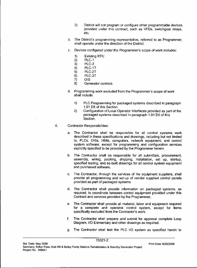
2) District will not program or configure other programmable devicesprovided under this contract, such as VFDs, switchgear relays,etc.
b. The District's programming representative, referred to as Programmer,shall operate under the direction of the District.
c. Devices configured under the Programmer's scope of work includes:
1) Existing RTU2) PLC-13) PLC-24) PLC-iT5) PLC-2T6) PLC-3T7) OIS8) Generator controls
d. Programming work excluded from the Programmer's scope of workshall include:
1) PLC Programming for packaged systems described in paragraph1.01 D5 of this Section.
2) Configuration of Local Operator Interfaces provided as part of thepackaged systems described in paragraph 1.01 D5 of thisSection.
4. Contractor Responsibilities:
a. The Contractor shall be responsible for all control systems workdescribed in these specifications and drawings, including but not limitedto, PLCs, OISs, HMIs, computers, network equipment, and controlsystem software, except for programming and configuration servicesexplicitly specified to be provided by the Programmer herein.
b. The Contractor shall be responsible for all submittals, procurement,assembly, wiring, packing, shipping, installation, set up, startup,specified testing, and as-built drawings for all control system equipmentand purchased software.
c. The Contractor, through the services of his equipment suppliers, shallprovide all programming and set-up of vendor supplied control panelsprovided as part of packaged systems.
d. The Contractor shall provide information on packaged systems, asrequired, to coordinate between control equipment provided under thisContract and services provided by the Programmer.
e. The Contractor shall provide all material, labor and equipment requiredfor a complete and operable control system, except for itemsspecifically excluded from the Contractor's work.
f. The Contractor shall prepare and submit for approval complete LoopDiagram, I/O Elementary and other drawings as required.
g. The Contractor shall test the PLC I/O system as specified herein to
13321-2Std. Date: May 2009 Print Date: 6/25/2009Seminary, Kirker Pass, Nob Hill & Bailey Pump Stations Rehabilitation & Standby Generator ProjectProject No. 109041
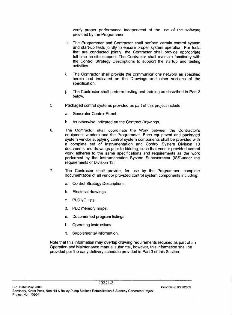
verify proper performance independent of the use of the softwareprovided by the Programmer-
h. The Programmer and Contractor shall perform certain control systemand start-up tests jointly to ensure proper system operation. For teststhat are conducted jointly, the Contractor shall provide appropriatefull-time on-site support. The Contractor shall maintain familiarity withthe Control Strategy Descriptions to support the startup and testingactivities.
i. The Contractor shall provide the communications network as specifiedherein and indicated on the Drawings and other sections of thespecification.
j. The Contractor shall perform testing and training as described in Part 3below.
5. Packaged control systems provided as part of this project include:
a. Generator Control Panel
b. As otherwise indicated on the Contract Drawings.
6. The Contractor shall coordinate the Work between the Contractor'sequipment vendors and the Programmer. Each equipment and packagedsystem vendor supplying control system components shall be provided witha complete set of Instrumentation and Control System Division 13documents and drawings prior to bidding, such that vendor provided controlwork adheres to the same specifications and requirements as the workperformed by the Instrumentation System Subcontractor (ISS)under therequirements of Division 13.
7. The Contractor shall provide, for use by the Programmer, complete
documentation of all vendor provided control system components including:
a. Control Strategy Descriptions.
b. Electrical drawings.
c. PLC I/O lists.
d. PLC memory maps.
e. Documented program listings.
f- Operating instructions.
g. Supplemental information.
Note that this information may overlap drawing requirements required as part of anOperation and Maintenance manual submittal, however, this information shall beprovided per the early delivery schedule provided in Part 3 of this Section.
13321-3Std. Date: May 2009 Print Date: 6/2512009Seminary, Kirker Pass, Nob Hill & Bailey Pump Stations Rehabilitation & Standby Generator ProjectProject No. 109041
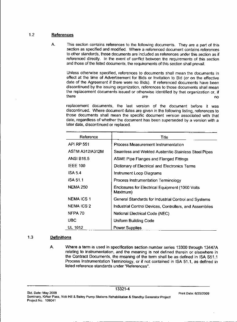
1.2 References
A. This section contains references to the following documents. They are a part of thissection as specified and modified. Where a referenced document contains referencesto other standards, those documents are included as references under this section as ifreferenced directly. In the event of conflict between the requirements of this sectionand those of the listed documents, the requirements of this section shall prevail-
Unless otherwise specified, references to documents shall mean the documents ineffect at the time of Advertisement for Bids or Invitation to Bid (or on the effectivedate of the Agreement if there were no Bids). If referenced documents have beendiscontinued by the issuing organization, references to those documents shall meanthe replacement documents issued or otherwise identified by that organization or, ifthere are no
replacement documents, the last version of the document before it wasdiscontinued. Where document dates are given in the following listing, references tothose documents shall mean the specific document version associated with thatdate, regardless of whether the document has been superseded by a version with alater date, discontinued or replaced.
Reference Title
API RP 551 Process Measurement Instrumentation
ASTM A312/A312M Seamless and Welded Austenitic Stainless Steel Pipes
ANSI B16.5 ASME Pipe Flanges and Flanged FittingsIEEE 100 Dictionary of Electrical and Electronics Terms
ISA 5.4 Instrument Loop DiagramsISA 51.1 Process Instrumentation Terminology
NEMA 250 Enclosures for Electrical Equipment (1000 VoltsMaximum)
NEMA ICS 1 General Standards for Industrial Control and SystemsNEMA ICS 2 Industrial Control Devices, Controllers, and Assemblies
NFPA 70 National Electrical Code (NEC)
UBC Uniform Building Code
UL 1012 Power Supplies
1.3 Definitions
A. Where a term is used in specification section number series 13300 through 13447Arelating to instrumentation, and the meaning is not defined therein or elsewhere inthe Contract Documents, the meaning of the term shall be as defined in ISA S51.1Process Instrumentation Terminology, or if not contained in ISA 51.1, as defined inlisted reference standards under "References".
13321-4Std. Date: May 2009 Print Date: 6/25/2009Seminary, Kirker Pass, Nob Hill & Bailey Pump Stations Rehabilitation & Standby Generator ProjectProject No. 109041
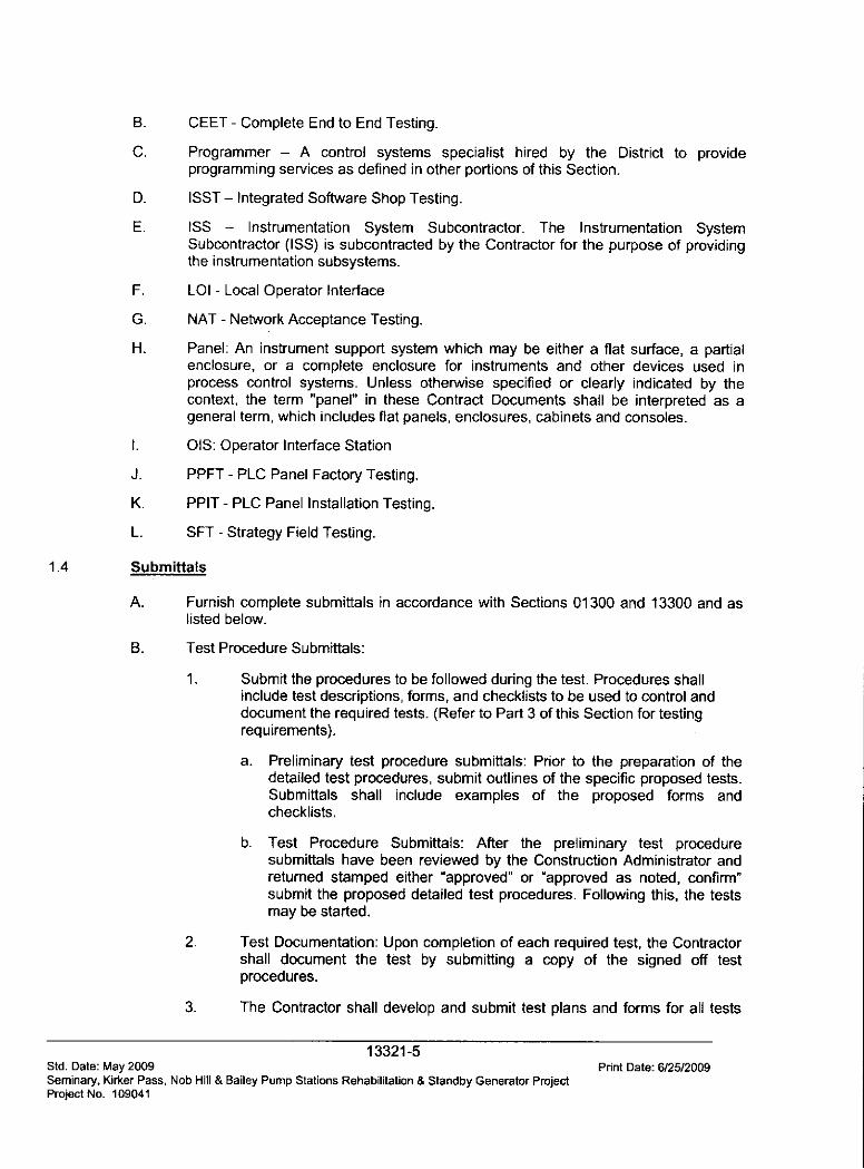
B. CEET - Complete End to End Testing.
C. Programmer - A control systems specialist hired by the District to provideprogramming services as defined in other portions of this Section.
D. ISST - Integrated Software Shop Testing.
E. ISS - Instrumentation System Subcontractor. The Instrumentation SystemSubcontractor (ISS) is subcontracted by the Contractor for the purpose of providingthe instrumentation subsystems.
F. LOI - Local Operator Interface
G. NAT - Network Acceptance Testing.
H. Panel: An instrument support system which may be either a flat surface, a partialenclosure, or a complete enclosure for instruments and other devices used inprocess control systems. Unless otherwise specified or clearly indicated by thecontext, the term "panel" in these Contract Documents shall be interpreted as ageneral term, which includes flat panels, enclosures, cabinets and consoles.
. OIS: Operator Interface Station
J. PPFT - PLC Panel Factory Testing.
K. PPIT - PLC Panel Installation Testing.
L. SFT - Strategy Field Testing.
1.4 Submittals
A. Furnish complete submittals in accordance with Sections 01300 and 13300 and aslisted below.
B. Test Procedure Submittals:
1. Submit the procedures to be followed during the test. Procedures shallinclude test descriptions, forms, and checklists to be used to control anddocument the required tests. (Refer to Part 3 of this Section for testingrequirements).
a. Preliminary test procedure submittals: Prior to the preparation of thedetailed test procedures, submit outlines of the specific proposed tests.Submittals shall include examples of the proposed forms andchecklists.
b- Test Procedure Submittals: After the preliminary test proceduresubmittals have been reviewed by the Construction Administrator andreturned stamped either "approved" or "approved as noted, confirm"submit the proposed detailed test procedures. Following this, the testsmay be started.
2. Test Documentation: Upon completion of each required test, the Contractorshall document the test by submitting a copy of the signed off testprocedures.
3. The Contractor shall develop and submit test plans and forms for all tests
13321-5Std. Date: May 2009 Print Date: 6/25/2009Seminary, Kirker Pass, Nob Hill & Bailey Pump Stations Rehabilitation & Standby Generator ProjectProject No. 109041
specified in this section, as well as all other control system related testing,except for the ISST and SFT tests. ISST and SFT test forms will beprovided by the District, through the services of the Programmer-
2.0 NOT USED
3.0 EXECUTION
3.1 Early Delivery Items
A. The Contractor shall expedite the approval and purchase of any of the followingequipment items which fall under the Contractors scope of supply. These itemsshall include, but not be limited to:
1. PLCs, including racks, power supplies and cards.
2. Workstations.
3. Communications Components.
4. Configuration Software.
5. Local Operator Interfaces.
6- Other items, as required, for a complete control system.
3.2 Coordination Meetings
A. In addition to the regular progress meetings, a minimum of three (3) coordinationmeetings shall be scheduled to coordinate the project control system software work.The District, the Contractor, the Programmer and appropriate packaged systemmanufacturers shall be in attendance.
B. Manufacturer's representatives shall have experience with the packaged systemcontrol components and software.
C. The first meeting shall be scheduled when approximately one-third of the contracttime has elapsed to review Control Software interfaces between the District'sProgrammer's work and the Contractor's work. Equipment deliveries and initial start-up issues shall also be discussed.
D. The second meeting shall be conducted when one-half to three-quarters of thecontract time has elapsed.
E. The final meeting shall be scheduled to review operational constraints associated
with testing and start up of the control system and related process equipment.
3.3 Testing
A. Tests (General)
1. As a minimum, testing shall include the following:
a. Unwitnessed Factory Tests (UFT).
b. Witnessed Factory Tests (WFT).
13321-6Std. Date: May 2009 Print Date: 6/2512009Seminary, Kirker Pass, Nob Hill & Bailey Pump Stations Rehabilitation & Standby Generator ProjectProject No. 109041
c. Operational Readiness Tests (ORT).
d. Functional Acceptance Tests (FAT).
e. 30-Day Acceptance Tests.
2. Each test shall be in the cause and effect format. The person conductingthe test shall initiate an input (cause) and upon the system's or subsystem'sproducing the correct result (effect), the specific test requirement will havebeen satisfied.
3. All tests shall be conducted in accordance with approved procedures, formsand checklist. Each specific test to be performed shall be described and aspace provided after it for sign off by the appropriate party after itssatisfactory completion.
4. Copies of these sign off test procedures, forms and checklists will constitutethe required test documentation.
5. Provide all special testing materials and equipment. Wherever possible,perform tests using actual process variables, equipment, and data. Where itis not practical to test with real process variables, equipment and data,provide suitable means of simulation. Define these simulation techniques inthe test procedures.
6. The Construction Administrator reserves the right to test or retest allspecified functions whether or not explic!tly stated in the approved TestProcedures until the functional requirements of the overall system are met.No additional compensation shall be provided for any required extendedtesting.
7. The Construction Administrator's decision shall be final regarding theacceptability and completeness of all testing.
8. No control equipment shall be shipped until the Construction Administratorhas received all test results, reviewed them, and given approval to ship theequipment.
9. The ISS shall furnish the services of field service engineers, all specialcalibration and test equipment and labor to perform the field tests.
10. Any testing or startup activity that requires the participation of theProgrammer shall be scheduled by the Contractor through writtennotification to the Construction Administrator and Programmer. Contractorshall provide regularly updated testing and startup schedules to theConstruction Administrator. In addition to any other form of notification,Contractor shall notify Programmer by email, or other mutually agreed uponmeans, two working days immediately prior to any testing or other activityrequiring the participation of the Programmer. Failure to properly notifyProgrammer shall result in rescheduling of test activity, solely at Contractorexpense and without an extension to the project completion schedule.
11. Testing and startup activities must be scheduled around treatment plantoperating needs. Testing and startup activities will require significant
13321-7Std. Date: May 2009 Print Date: 6/2512009Seminary, Kirker Pass, Nob Hill & Bailey Pump Stations Rehabilitation & Standby Generator ProjectProject No. 109041

coordination with plant staff and scheduling around facility operationalconstraints. Startup restrictions and requirements in this Section areminimums. Additional requirements are specified in other Sections of theContract Documents-
12. The Contractor shall not start any testing activity that cannot be completedby the end of the work week if so doing would disrupt treatment operations.Testing and startup activities shall not be conducted on Fridays or workingdays immediately prior to an District staff holiday.
13. Testing and startup shall be scheduled to allow proper operations stafftraining by the Contractor and Construction Administrator prior to puttingequipment into regular service.
B. Unwitnessed Factory Tests (UFT)
1. The control system equipment, except for primary elements, final controlelements, and field mounted transmitters, shall be interconnected andtested by the Contractor to ensure the system will operate as specified.
2. The purpose of the test shall be to verify the functionality, performance andstability of the hardware. The system must operate continuously for48 hours trouble free.
3. All panels, consoles and assemblies shall be inspected and tested to verifythat they are in conformance with related submittals, Specifications andDrawings. All analog and discrete input/output points shall be simulated toensure proper wiring.
4. During the tests all digital system hardware shall be operated for at leastfive days continuously without a failure to verify the system is capable ofcontinuous operation.
C. Witnessed Factory Test (WFT)
1. Implicit in the scheduling of the witnessed factory test (WFT) is theassumption that the Contractor has determined through prior, unwitnessedtests and quality assurance programs that the equipment is ready forshipment.
2. Prior to start of the WFT, all previous unwitnessed test results and formsshall have been submitted to the Construction Administrator for review andapproval.
3. As part of the factory testing, all PLC system components shall beassembled and tested in their enclosures at the Contractor's panelassembly facility, which shall be located no more than 100 miles fromConcord, California. The test set up shall include a temporary network thatincludes all network components.
4. The Contractor shall notify the District and Construction Administrator inwriting that the system is ready for the WFT and allow the District andConstruction Administrator to schedule a test date within 21 days of receipt
13321-8Std- Date: May 2009 Print Date: 6/25/2009Seminary, Kirker Pass, Nob Hill & Bailey Pump Stations Rehabilitation & Standby Generator ProjectProject No. 109041
of the "Ready to Test" letter. At the time of notification, the Contractor shallsubmit any revisions to the detailed test procedure previously approved bythe Construction Administrator in the project system plan.
5. The purpose of the test shall be to verify the functionality, performance andstability of the hardware. The system must operate continuously for96 hours trouble free. Successful completion of this test, as determined bythe District and Construction Administrator, shall be the basis for approval ofthe system to be shipped to the site.
6. All system tests specified for the unwitnessed factory test (UFT) shall berepeated. Additional tests shall be performed. All temporary cablingprovided during the UFT shall be provided for the WFT. This includes a 100percent check of all I/O to the interface terminal blocks and verification of allcommunications networks.
7. The various tests performed during the WFT shall be designed todemonstrate that hardware fulfills all the requirements of the specifications.The test conditions shall resemble, as closely as possible, the actualinstalled conditions. Any additional hardware or software that may berequired to successfully verify system operation shall be supplied at noadditional cost.
8. A complete system checklist shall be available during the test for recordingresults of selected points.
9. During the test for a period of time equal to at least 20 percent of the testduration, the Construction Administrator and Programmer shall haveunrestricted access to the system to perform ad hoc testing.
10. All control panels shall be included in these tests.
11. Perform PLC Panel Testing (PPFT) (by Contractor). The test shall confirmthat all control system equipment has been completely and correctlyassembled prior to shipment to the field. The panel shall be physicallyinspected for proper construction, assembly, wire tagging, fusing, labelingand general workmanship. Electrical tests shall be performed to verify theproper operation of all components and that the connections are correctfrom the field terminals to the PLC registers. The Contractor shall providean additional computer for testing purposes with additional PLCprogramming software installed, connect it to the PLC being tested, andperform the tests. Any computers and software delivered to the District orProgrammer shall not be used for this purpose. After the completion of theelectrical testing procedures, each cabinet shall remain energized for aperiod of not less than 24 hours, without component failures, prior toshipment from the factory.
12. Integrated Software Shop Testing (ISST) (Joint Programmer and Contractortest). After the completion of the PPF Testing, the Programmer shall loadthe process control software into the PLC and demonstrate the operation ofthe control system software. The testing shall take place at the Contractor'sfacility. The Contractor shall allow approximately 1 work day in theConstruction Schedule (per Section 01310 - Process Schedule) per 50
13321-9Std. Date: May 2009 Print Date: 6125/2009Seminary, Kirker Pass, Nob Hill & Bailey Pump Stations Rehabilitation & Standby Generator ProjectProject No. 109041

physical I/O points to accommodate ISST Testing. The Contractor shallprovide full time personnel to support the activities of the Programmerduring this test. The District reserves the right to waive the ISST, withoutpenalty.
13. Any components found to be defective during the PPFT or the ISST shall bereplaced or repaired by the Contractor prior to shipment to the project site.
14. All deficiencies identified during these tests shall be corrected and retestedprior to completion of the WFT as determined by the District andConstruction Administrator.
15. The following documentation shall be made available by the Contractor tothe Construction Administrator and Programmer at the test site both beforeand during the WFT:
a. All drawings and specifications, addenda and change orders.
b. Master copy of the test procedure.
c. List of the equipment to be tested including make, model and serialnumber.
d. Design-related hardware and software submittal applicable to theequipment being tested.
16. All test data and results shall be logged by the Contractor, and certifiedcopies of the logs shall be provided to the Construction Administrator.
17. The "punch list" of deficiencies shall be corrected prior to equipmentshipment to the job site.
D. Operational Readiness Tests (ORT)
1. General: Prior to startup and the Functional Acceptance Test, the entiresystem shall be certified (inspected, tested and documented) by theContractor that it is ready for operation. Note that the control system testingincludes the operation of equipment items outside of the Division 13 scopeof work. The Contractor shall coordinate the construction activities such thatinstrumentation and equipment items are operable during the testing period.Operational Readiness testing shall not begin until permanent power, andother service connections, are provided for all equipment items. Forequipment items requiring vendor provided start up services, this work shallbe coordinated to maximize the effectiveness of the field tests.
2. PLC Panel Installed Testing (PPIT) (by Contractor)
a. The Contractor shall inspect the installed PLC cabinets and verify thefollowing:
1) The cabinet and components are not damaged.
2) All components are installed and wiring has been completed.
13321-10Std. Dale: May 2009 Print Date: 6/25/2009Seminary, Kirker Pass, Nob Hill & Bailey Pump Stations Rehabilitation & Standby Generator ProjectProject No. 109041
3) All fuses are installed in fuse holders.
4) Cabinet wiring is free from short circuits.
b. The Contractor shall energize the cabinets and power up thecomponents.
c. The Contractor shall verify that all power supplies are operatingproperly.
d. The Contractor shall verify that all PLC cards are installed andfunctional; and that the PLC is ready to accept the PLC program.
e. Provide written certification that PPIT has been completed satisfactorilyprior to scheduling or starting BEET or loop acceptance testing.
3. Basic End-to-End Testing (BEET) (by Contractor)
a. For each and every analog and discrete circuit, the Contractor shallperform Basic End-to-End Testing (BEET). This includes, but is notlimited to, all local control panels, MCCs, and hardwired circuits incontrol panels.
b. Connect a computer equipped with PLC programming software to theassociated PLC.
c. For each input, activate the signal at the primary field device, either bycreating necessary process and equipment conditions or bydisconnecting the wires at the field device and simulating the inputsignal. At the PLC, using the PLC programming software, verify properreceipt of the signal.
d. For each output signal from the PLC, activate the PLC output signalusing the PLC programming software, and verify proper receipt of thesignal at the controlled device in the field, either by observingequipment operation or by disconnecting the wires at the equipmentand verifying proper receipt of the signal.
e. Verify proper signal receipt at all intermediate devices, such asindicators, signal trip and relay modules, etc.
4. Loop/Component Inspections and Tests (by Contractor)
a. The entire system shall be checked for proper installation, calibratedand adjusted on a loop-by-loop and component-by-component basis toensure that it is in conformance with related submittals and theseSpecifications.
b. The Loop/Component Inspections and Tests shall be implementedusing Construction Administrator-approved forms and checklists.
c. Each loop shall have a Loop Status Report to organize and track itsinspection, adjustment and calibration. These reports shall include thefollowing information and check off items with spaces for sign off by testpersonnel:
1) Project Name.
13321-11Std. Date: May 2009 Print Date: 6/25/2009Seminary, Kirker Pass, Nob Hill & Bailey Pump Stations Rehabilitation & Standby Generator ProjectProject No. 109041
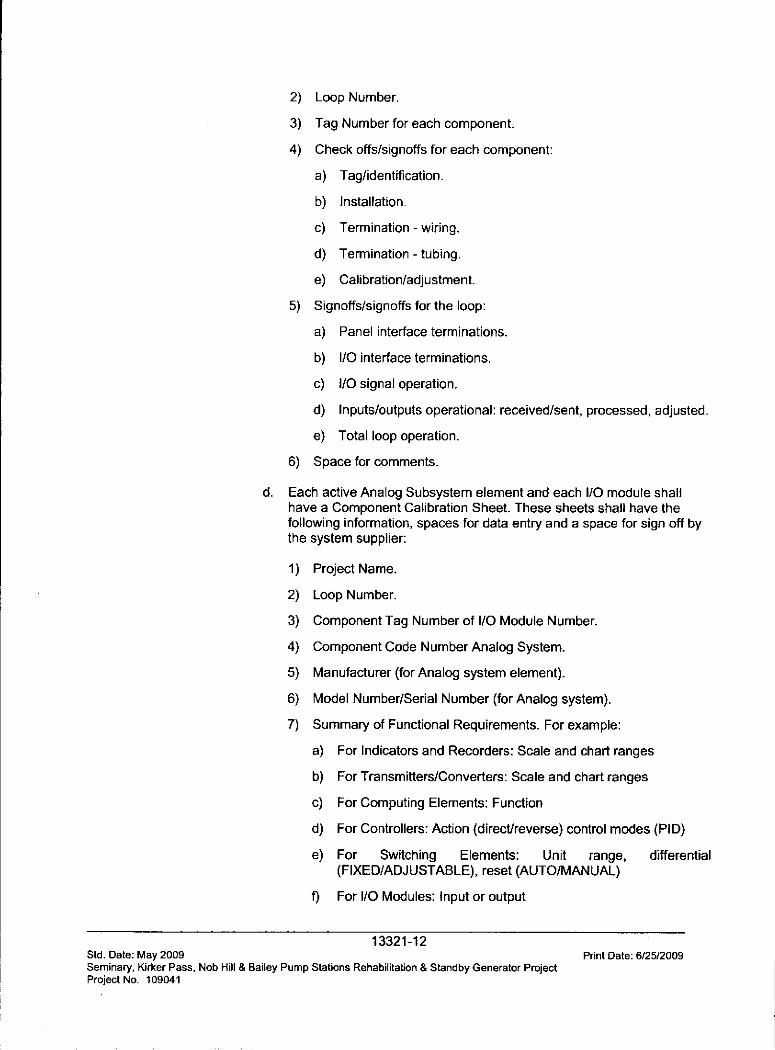
2) Loop Number.
3) Tag Number for each component.
4) Check offs/signoffs for each component:
a) Tag/identification.
b) Installation.
c) Termination - wiring.
d) Termination - tubing.
e) Calibration/adjustment
5) Signoffs/signoffs for the loop:
a) Panel interface terminations.
b) I/O interface terminations.
c) I/O signal operation.
d) Inputs/outputs operational: received/sent, processed, adjusted.
e) Total loop operation.
6) Space for comments.
d. Each active Analog Subsystem element and each I/O module shallhave a Component Calibration Sheet. These sheets shall have thefollowing information, spaces for data entry and a space for sign off bythe system supplier:
1) Project Name.
2) Loop Number.
3) Component Tag Number of I/O Module Number.
4) Component Code Number Analog System.
5) Manufacturer (for Analog system element).
6) Model Number/Serial Number (for Analog system).
7) Summary of Functional Requirements. For example:
a) For Indicators and Recorders: Scale and chart ranges
b) For Transmitters/Converters: Scale and chart ranges
c) For Computing Elements: Function
d) For Controllers: Action (direct/reverse) control modes (PID)
e) For Switching Elements: Unit range, differential(FIXED/ADJUSTABLE), reset (AUTO/MANUAL)
f For I/O Modules: Input or output
13321-12Std. Date: May 2009 Print Date: 612512009Seminary, Kirker Pass, Nob Hill & Bailey Pump Stations Rehabilitation & Standby Generator ProjectProject No. 109041
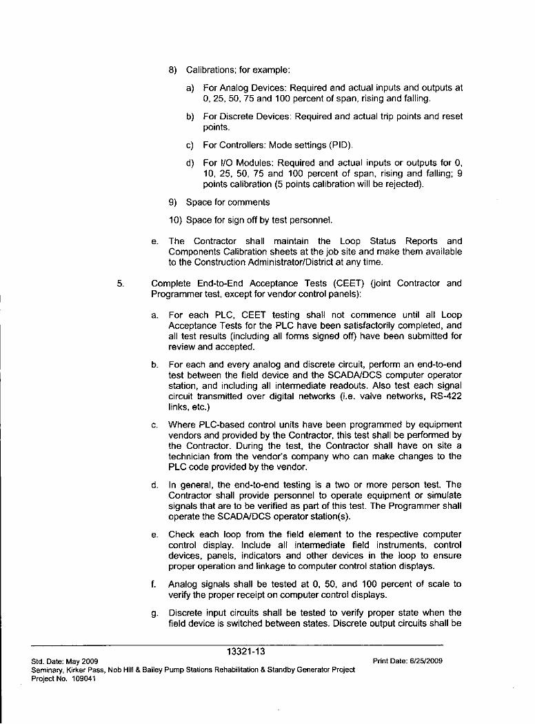
8) Calibrations; for example:
a) For Analog Devices: Required and actual inputs and outputs at0, 25, 50, 75 and 100 percent of span, rising and falling.
b) For Discrete Devices: Required and actual trip points and resetpoints.
c) For Controllers: Mode settings (PID).
d) For I/O Modules: Required and actual inputs or outputs for 0,10, 25, 50, 75 and 100 percent of span, rising and falling; 9points calibration (5 points calibration will be rejected).
9) Space for comments
10) Space for sign off by test personnel.
e. The Contractor shall maintain the Loop Status Reports andComponents Calibration sheets at the job site and make them availableto the Construction Administrator/District at any time.
5. Complete End-to-End Acceptance Tests (CEET) (joint Contractor andProgrammer test, except for vendor control panels):
a. For each PLC, CEET testing shall not commence until all LoopAcceptance Tests for the PLC have been satisfactorily completed, andall test results (including all forms signed off) have been submitted forreview and accepted.
b. For each and every analog and discrete circuit, perform an end-to-endtest between the field device and the SCADA/DCS computer operatorstation, and including all intermediate readouts. Also test each signalcircuit transmitted over digital networks (i.e. valve networks, RS-422links, etc.)
c. Where PLC-based control units have been programmed by equipmentvendors and provided by the Contractor, this test shall be performed bythe Contractor. During the test, the Contractor shall have on site atechnician from the vendor's company who can make changes to thePLC code provided by the vendor.
d. In general, the end-to-end testing is a two or more person test. TheContractor shall provide personnel to operate equipment or simulatesignals that are to be verified as part of this test. The Programmer shalloperate the SCADA/DCS operator station(s).
e. Check each loop from the field element to the respective computercontrol display. Include all intermediate field instruments, controldevices, panels, indicators and other devices in the loop to ensureproper operation and linkage to computer control station displays.
f. Analog signals shall be tested at 0, 50, and 100 percent of scale toverify the proper receipt on computer control displays.
g. Discrete input circuits shall be tested to verify proper state when thefield device is switched between states. Discrete output circuits shall be
13321-13Std. Date: May 2009 Print Date: 6/25/2009Seminary, Kirker Pass, Nob Hill & Bailey Pump Stations Rehabilitation & Standby Generator ProjectProject No. 109041
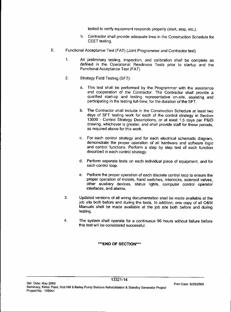
tested to verify equipment responds properly (start, stop, etc.).
h. Contractor shall provide adequate time in the Construction Schedule forCEET testing.
E_ Functional Acceptance Test (FAT) (Joint Programmer and Contractor test)
1. All preliminary testing, inspection, and calibration shall be complete asdefined in the Operational Readiness Tests prior to startup and theFunctional Acceptance Test (FAT)
2. Strategy Field Testing (SFT):
a. This test shall be performed by the Programmer with the assistanceand cooperation of the Contractor. The Contractor shall provide aqualified start-up and testing representative on-site, assisting andparticipating in the testing full-time, for the duration of the SFT.
b. The Contractor shall include in the Construction Schedule at least twodays of SFT testing work for each of the control strategy in Section13000 - Control Strategy Descriptions, or at least 1.5 days per P&IDdrawing, whichever is greater, and shall provide staff for these periods,as required above for this work.
c- For each control strategy and for each electrical schematic diagram,demonstrate the proper operation of all hardware and software logicand control functions. Perform a step by step test of each functiondescribed in each control strategy.
d. Perform separate tests on each individual piece of equipment, and foreach control loop.
e. Perform the proper operation of each discrete control loop to ensure theproper operation of motors, hand switches, interlocks, solenoid valves,other auxiliary devices, status lights, computer control operatorinterfaces, and alarms.
3. Updated versions of all wiring documentation shall be made available at thejob site both before and during the tests. In addition, one copy of all O&MManuals shall be made available at the job site both before and duringtesting.
4. The system shall operate for a continuous 96 hours without failure beforethis test will be considered successful.
***END OF SECTION***
13321-14Std. Date: May 2009 Pnnt Date: 6/2512009Seminary, Kirker Pass, Nob Hill & Bailey Pump Stations Rehabilitation & Standby Generator ProjectProject No. 109041
Related Documents


![SECURITIES AND EXCHANGE COMMISSION Integrity Life ... · SECURITIES AND EXCHANGE COMMISSION [Release Number IC-27677; File No. 812-13321] Integrity Life Insurance Company, et al.](https://static.cupdf.com/doc/110x72/5f0a9ae47e708231d42c73e1/securities-and-exchange-commission-integrity-life-securities-and-exchange-commission.jpg)