Hakuba 26PPM Laser Printer - Base Engine Technical Manual 12-1 Version 1.0 Parts List Section 12 - Parts List Contents PL1.1 Covers I . . . . . . . . . . . . . . . . . . . . . . . . . . . . . . . . . . . . . . . . . . . . . . . . . . . . . . . . . . . . . . . . 12-2 PL1.2 Covers II . . . . . . . . . . . . . . . . . . . . . . . . . . . . . . . . . . . . . . . . . . . . . . . . . . . . . . . . . . . . . . . 12-4 PL2.1 Paper Cassette I . . . . . . . . . . . . . . . . . . . . . . . . . . . . . . . . . . . . . . . . . . . . . . . . . . . . . . . . . 12-6 PL2.2 Paper Cassette II . . . . . . . . . . . . . . . . . . . . . . . . . . . . . . . . . . . . . . . . . . . . . . . . . . . . . . . . . 12-8 PL3.1 Paper Feeder . . . . . . . . . . . . . . . . . . . . . . . . . . . . . . . . . . . . . . . . . . . . . . . . . . . . . . . . . . . 12-10 PL4.1 Chute MBF . . . . . . . . . . . . . . . . . . . . . . . . . . . . . . . . . . . . . . . . . . . . . . . . . . . . . . . . . . . . 12-12 PL5.1 P/H Assy . . . . . . . . . . . . . . . . . . . . . . . . . . . . . . . . . . . . . . . . . . . . . . . . . . . . . . . . . . . . . . 12-14 PL6.1 Chute Trans & Fuser . . . . . . . . . . . . . . . . . . . . . . . . . . . . . . . . . . . . . . . . . . . . . . . . . . . . . 12-16 PL7.1 Exit . . . . . . . . . . . . . . . . . . . . . . . . . . . . . . . . . . . . . . . . . . . . . . . . . . . . . . . . . . . . . . . . . . . 12-18 PL8.1 Drive & Xerographics . . . . . . . . . . . . . . . . . . . . . . . . . . . . . . . . . . . . . . . . . . . . . . . . . . . . . 12-20 PL9.1 Frame & Size Sensor . . . . . . . . . . . . . . . . . . . . . . . . . . . . . . . . . . . . . . . . . . . . . . . . . . . . 12-22 PL10.1 Electrical . . . . . . . . . . . . . . . . . . . . . . . . . . . . . . . . . . . . . . . . . . . . . . . . . . . . . . . . . . . . . . 12-24 Using the Parts List 1. The numbers shown in each illustration correspond to the parts list number for that illustration. 2. Throughout this manual, parts are identified by the prefix “PL”, followed by a number, a decimal point, and another number. For example, PL3.1.12 means the part is item 12 of parts list 3.1. 3. The capital letters “C”, “E”, and “S” shown in an illustration stand for C-ring, E-ring, and Screw, respec- tively. 4. A shaded triangle t in an illustration indicates the item is part of an assembly. 5. The notation “with X~Y” following an part name indicates an assembly that is made up of components X through Y. For example, “1 (with 2~4)” means part 1 consists of part 2, part 3, and part 4. 6. The notation "RS" means that the part is a requested spare. Part numbers for these parts will be pro- vided as soon as they are available. 7. An asterisk * following a part name indicates the page contains a note about this part. 8. The notation “J1<>J2 and P2” is attached to a wire harness. It indicates that connector jack 1 is attached to one end of the wire harness and connector jack 2 is attached to the other end that is plugged into plug 2. 9. A notation "(part of item 1.1)" indicates that the part is included with item 1.2.1 (PL1.2, line item 1).

Welcome message from author
This document is posted to help you gain knowledge. Please leave a comment to let me know what you think about it! Share it to your friends and learn new things together.
Transcript
Hakuba 26PPM Laser Printer - Base Engine Technical Manual 12-1Version 1.0
Parts List
Section 12 - Parts List Contents
PL1.1 Covers I . . . . . . . . . . . . . . . . . . . . . . . . . . . . . . . . . . . . . . . . . . . . . . . . . . . . . . . . . . . . . . . . 12-2PL1.2 Covers II . . . . . . . . . . . . . . . . . . . . . . . . . . . . . . . . . . . . . . . . . . . . . . . . . . . . . . . . . . . . . . . 12-4PL2.1 Paper Cassette I . . . . . . . . . . . . . . . . . . . . . . . . . . . . . . . . . . . . . . . . . . . . . . . . . . . . . . . . . 12-6PL2.2 Paper Cassette II . . . . . . . . . . . . . . . . . . . . . . . . . . . . . . . . . . . . . . . . . . . . . . . . . . . . . . . . . 12-8PL3.1 Paper Feeder. . . . . . . . . . . . . . . . . . . . . . . . . . . . . . . . . . . . . . . . . . . . . . . . . . . . . . . . . . . 12-10PL4.1 Chute MBF . . . . . . . . . . . . . . . . . . . . . . . . . . . . . . . . . . . . . . . . . . . . . . . . . . . . . . . . . . . . 12-12PL5.1 P/H Assy . . . . . . . . . . . . . . . . . . . . . . . . . . . . . . . . . . . . . . . . . . . . . . . . . . . . . . . . . . . . . . 12-14PL6.1 Chute Trans & Fuser . . . . . . . . . . . . . . . . . . . . . . . . . . . . . . . . . . . . . . . . . . . . . . . . . . . . . 12-16PL7.1 Exit. . . . . . . . . . . . . . . . . . . . . . . . . . . . . . . . . . . . . . . . . . . . . . . . . . . . . . . . . . . . . . . . . . . 12-18PL8.1 Drive & Xerographics. . . . . . . . . . . . . . . . . . . . . . . . . . . . . . . . . . . . . . . . . . . . . . . . . . . . . 12-20PL9.1 Frame & Size Sensor . . . . . . . . . . . . . . . . . . . . . . . . . . . . . . . . . . . . . . . . . . . . . . . . . . . . 12-22PL10.1 Electrical . . . . . . . . . . . . . . . . . . . . . . . . . . . . . . . . . . . . . . . . . . . . . . . . . . . . . . . . . . . . . . 12-24
Using the Parts List1. The numbers shown in each illustration correspond to the parts list number for that illustration. 2. Throughout this manual, parts are identified by the prefix “PL”, followed by a number, a decimal point,
and another number. For example, PL3.1.12 means the part is item 12 of parts list 3.1.3. The capital letters “C”, “E”, and “S” shown in an illustration stand for C-ring, E-ring, and Screw, respec-
tively.4. A shaded triangle t in an illustration indicates the item is part of an assembly.5. The notation “with X~Y” following an part name indicates an assembly that is made up of components
X through Y. For example, “1 (with 2~4)” means part 1 consists of part 2, part 3, and part 4.6. The notation "RS" means that the part is a requested spare. Part numbers for these parts will be pro-
vided as soon as they are available.7. An asterisk * following a part name indicates the page contains a note about this part.8. The notation “J1<>J2 and P2” is attached to a wire harness. It indicates that connector jack 1 is
attached to one end of the wire harness and connector jack 2 is attached to the other end that isplugged into plug 2.
9. A notation "(part of item 1.1)" indicates that the part is included with item 1.2.1 (PL1.2, line item 1).

12-2 Hakuba 26PPM Laser Printer - Base Engine Technical ManualVersion 1.0
Parts List
PL1.1 Covers I
Hakuba 26PPM Laser Printer - Base Engine Technical Manual 12-3Version 1.0
Parts List
PL1.1 Covers IITEM PART NUMBER PART NAME
1 048E64591 COVER LEFT2 048K76270 COVER ASSY I/F3 ---4 048E64642 COVER OPTION5 048K76455 COVER ASSY TOP (with 23)6 802K51410 CONTROL ASSY PANEL (with 7)7 162K43680 HARNESS ASSY PANEL (J362-J363)8 048E64612 COVER RIGHT9 048K76243 COVER ASSY FRONT (with 10~13,15~17,20~22,26)10 --- COVER FRONT11 --- LATCH ASSY L12 --- LEVER13 --- LATCH ASSY R14 003E48991 STOPPER COVER15 --- CHUTE ENV16 003E43880 STOPPER TRAY17 050K37121 TRAY ASSY MBF18 ---19 048E64624 COVER FRONT L/H20 --- CHUTE MBF21 --- ENV GEAR COVER22 354W24254 CLIP23 --- SPRING EARTH EXIT 224 --- JOINT SPRING25 --- SPRING FRONT26 004K01870 CLEANING PAD ASSY27 --- CONTROL PANEL OVERLAY

12-4 Hakuba 26PPM Laser Printer - Base Engine Technical ManualVersion 1.0
Parts List
PL1.2 Covers II
Hakuba 26PPM Laser Printer - Base Engine Technical Manual 12-5Version 1.0
Parts List
PL1.2 Covers IIITEM PART NUMBER PART NAME
1 --- SPRING LATCH2 --- LATCH L3 --- LATCH R4 --- COVER LATCH5 --- COVER REAR6 --- ARM DIRECTION7 --- CAP ENVELOPE8 --- CHUTE ASSY FACE UP9 --- STOPPER PIVOT R10 003E46120 STOPPER11 --- GUIDE RAIL DUP L12 --- GUIDE RAIL DUP R13 --- OVER FACE UP98 600K79530 KIT CAP ENVELOPE (qty. 2 of item 7)99 802K12743 COVER ASSY REAR (with 1~9)

12-6 Hakuba 26PPM Laser Printer - Base Engine Technical ManualVersion 1.0
Parts List
PL2.1 Paper Cassette I
Hakuba 26PPM Laser Printer - Base Engine Technical Manual 12-7Version 1.0
Parts List
PL2.1 Paper Cassette IITEM PART NUMBER PART NAME
1 --- CASSETTE ASSY (with 2~23)2 --- PLATE ASSY BOTTOM3 ---4 ---5 604K04810 KIT GUIDE END6 --- HOUSING EXTENSION7 --- SLIDE RACK8 --- SPRING EXTENSION9 --- LATCH SPRING10 --- PLATE SIZE11 --- BASE EXTENSION12 --- GUIDE SIZE L13 --- GUIDE ASSY SIDE R14 --- LINK15 --- BASE CST16 --- RACK17 --- PINION18 --- CASSETTE SUB ASSY [same PL2.21]19 --- ACTUATOR CST20 --- COVER ACTUATOR21 --- LABEL BUTTON22 --- LABEL INDICATOR23 --- LABEL CST INSTRUCTION

12-8 Hakuba 26PPM Laser Printer - Base Engine Technical ManualVersion 1.0
Parts List
PL2.2 Paper Cassette II
Hakuba 26PPM Laser Printer - Base Engine Technical Manual 12-9Version 1.0
Parts List
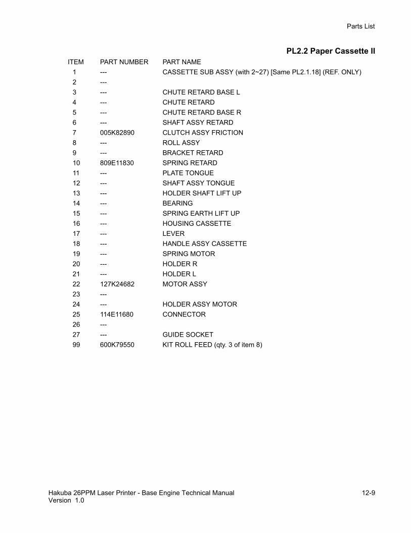
PL2.2 Paper Cassette IIITEM PART NUMBER PART NAME
1 --- CASSETTE SUB ASSY (with 2~27) [Same PL2.1.18] (REF. ONLY)2 ---3 --- CHUTE RETARD BASE L4 --- CHUTE RETARD5 --- CHUTE RETARD BASE R6 --- SHAFT ASSY RETARD7 005K82890 CLUTCH ASSY FRICTION8 --- ROLL ASSY9 --- BRACKET RETARD10 809E11830 SPRING RETARD11 --- PLATE TONGUE12 --- SHAFT ASSY TONGUE13 --- HOLDER SHAFT LIFT UP14 --- BEARING15 --- SPRING EARTH LIFT UP16 --- HOUSING CASSETTE17 --- LEVER18 --- HANDLE ASSY CASSETTE19 --- SPRING MOTOR20 --- HOLDER R21 --- HOLDER L22 127K24682 MOTOR ASSY23 ---24 --- HOLDER ASSY MOTOR25 114E11680 CONNECTOR26 ---27 --- GUIDE SOCKET99 600K79550 KIT ROLL FEED (qty. 3 of item 8)

12-10 Hakuba 26PPM Laser Printer - Base Engine Technical ManualVersion 1.0
Parts List
PL3.1 Paper Feeder

Hakuba 26PPM Laser Printer - Base Engine Technical Manual 12-11Version 1.0
Parts List
PL3.1 Paper FeederITEM PART NUMBER PART NAME
1 022K66290 ROLL ASSY TURN (with 2)2 121K20151 CLUTCH ASSY TURN3 --- SPRING EXTENSION4 809E11630 SPRING CHUTE5 --- COVER CST FEED6 120E16960 ACTUATOR N/P7 830E18132 SUPPORT ACTUATOR8 --- FRAME ASSY FEEDER9 --- CLAMP10 --- SPRING LATCH L11 --- ACTUATER LOW PAPER12 --- SUPPORT ACTUATOR L/P13 130E81970 SENSOR PHOTO :FACE CONTROL,LOW PAPER14 162K47211 HARNESS ASSY N/SNSR (J66-J661,J662)15 ---16 ---17 --- ROLL 718 --- COVER FEEDER19 600K79320 FEEDER ASSY (with 20~29)20 --- SHAFT FEED21 --- BEARING22 --- SUPPORT ASSY NUDGER23 --- CLUTCH NUDGER24 --- CLUTCH GEAR25 --- CLUTCH ASSY O/W26 --- ROLL ASSY27 --- GEAR 25T28 --- GEAR 31T29 --- SPRING NUDGER30 --- GEAR 431 --- GEAR 232 --- COVER GEAR33 --- BRACKET34 --- GEAR 335 --- GEAR 136 160K52781 PWBA FEEDER37 121K19010 CLUTCH ASSY FEED38 --- BEARING39 --- HARNESS ASSY N/MOT (J67-J671)40 --- SOCKET41 --- SUPPORT ROLL-742 --- CHUTE TURN43 --- STOPPER CST44 --- CLAMP96 600K79640 KIT SOCKET & HARNESS (39, 40) (same as )97 600K79652 KIT ACTUATOR & SUPPORT (11, 12)98 022K56902 KIT FEEDER ASSY (1~40)99 600K79550 KIT ROLL FEED (qty. 3 of item 26)

12-12 Hakuba 26PPM Laser Printer - Base Engine Technical ManualVersion 1.0
Parts List
PL4.1 Chute MBF

Hakuba 26PPM Laser Printer - Base Engine Technical Manual 12-13Version 1.0
Parts List
PL4.1 Chute MBFITEM PART NUMBER PART NAME
1 054K22391 CHUTE MBF ASSY (with 2~31)2 --- ROLL ASSY MBF (with 3~6,28)3 --- SHAFT ASSY MBF4 --- CAM PICK UP MBF5 --- CORE6 022K50815 ROLL ASSY MBF7 --- BEARING8 --- TRAY BOTTOM ASSY (with 11,12)9 ---10 ---11 --- TRAY BOTTOM12 120E17121 ACTUATOR N/P MBF13 --- SPRING TRAY BOTTOM MBF14 --- BEARING EXIT15 019K94573 PAD ASSY RETARD16 ---17 ---18 ---19 130E81970 SENSOR PHOTO :PAPER SET20 --- PLATE EARTH MBF21 --- CHUTE ASSY MBF22 ---23 121E85920 SOLENOID PICK UP24 809E20171 SPRING MBF25 007E54661 GEAR PICK UP26 --- PLATE ENV CONECTOR27 113K82141 CONECTOR ASSY ENV28 --- CAM PICK UP MBF (LEFT)29 162K47021 HARNESS ASSY MBF NOPAP (J45-J451)30 --- PLATE ENV ASSY (with 26,27) . . . . . . . . . . . . . . . . . . 31 019K96830 PAD ASSY PICK UP32 --- GUIDE ROLL

12-14 Hakuba 26PPM Laser Printer - Base Engine Technical ManualVersion 1.0
Parts List
PL5.1 P/H Assy

Hakuba 26PPM Laser Printer - Base Engine Technical Manual 12-15Version 1.0
Parts List
PL5.1 P/H AssyITEM PART NUMBER PART NAME
1 --- TONER SENSOR2 --- HOLDER TONER SENSOR3 --- SPRING TONER SENSOR4 054K14985 P/H ASSY (with 2,5~31,36~39)5 --- ROLL REGI METAL6 --- CHUTE UPPER ASSY7 059K11911 ROLL REGI RUBBER8 --- CHUTE INLET9 --- SPRING EARTH BOTTOM10 120E13331 ACTUATOR REGI11 809E19722 SPRING SENSOR REGI12 130E81970 SENSOR PHOTO :REGI13 --- BEARING METAL14 809E22950 SPRING REGI15 007E54671 GEAR REGI METAL16 007E54681 GEAR REGI RUBBER17 --- BEARING RUBBER R18 --- BEARING RUBBER L19 121E85821 CLUTCH REGI20 --- CHUTE BOTTOM UPPER21 --- SPRING EARTH RIGHT22 --- SPRING EARTH CENTER23 --- SCREW EARTH24 --- SPRING LEFT25 --- RESISTOR26 --- CHUTE BOTTOM LOWER27 --- CHUTE CST28 162K47011 HARNESS ASSY REGI (J43-J432,J433)29 --- SPRING TORSION30 --- HANDLE LEVER31 --- BEARING METAL R32 --- HARNESS ASSY TONER SENSOR (J42-J421)33 --- CUSHION TNS34 006E60981 SHAFT 1435 007E54650 GEAR 1436 809E19030 SPRING REGI L37 --- LABEL INLET38 --- CLAMP39 --- CAP INLET99 600K79381 KIT TONER SENSOR (with 1~3, 32, 33)

12-16 Hakuba 26PPM Laser Printer - Base Engine Technical ManualVersion 1.0
Parts List
PL6.1 Chute Trans & Fuser

Hakuba 26PPM Laser Printer - Base Engine Technical Manual 12-17Version 1.0
Parts List
PL6.1 Chute Trans & FuserITEM PART NUMBER PART NAME
1 --- BTR CHUTE ASSY (with 2~6,13)2 022K55010 BTR ASSY3 054K15000 CHUTE TRANS ASSY (with 4~6,13)4 --- BEARING BTR SUP5 --- SPRING BTR6 --- CHUTE TRANS (REFERENCE ONLY)7 126K14941 120V FUSER ASSY (with 15)-- 126K14941 220V FUSER ASSY (with 15)8 ---9 ---10 --- WIRE ASSY DTS11 --- WIRE ASSY TR12 962K06310 120V HARNESS ASSY FUSER-M (J271,J11,J27,J262)-- 962K06310 220V HARNESS ASSY FUSER-M (J271,J11,J27,J262)13 --- SPRING BTR L14 --- HOLDER BTR15 --- THUMB SCREW

12-18 Hakuba 26PPM Laser Printer - Base Engine Technical ManualVersion 1.0
Parts List
PL7.1 Exit

Hakuba 26PPM Laser Printer - Base Engine Technical Manual 12-19Version 1.0
Parts List
PL7.1 ExitITEM PART NUMBER PART NAME
1 105K14904 ELIMINATOR ASSY EXIT2 120E13350 ACTUATOR FULL STACK3 --- GATE EXIT4 --- SPRING EXIT5 --- GEAR EXIT-176 --- BEARING EXIT7 059K11950 ROLL ASSY MID-18 --- ROLL PINCH EXIT OUT9 --- ROLL PINCH EXIT10 --- SPRING PINCH EXIT11 059K11960 ROLL ASSY MID-212 --- ROLL PINCH13 --- SPRING PINCH MID14 --- SPRING PINCH15 --- CHUTE EXIT16 130E81970 SENSOR PHOTO :EXIT17 162K46981 HARNESS ASSY FS SNR (J31-J311)18 --- COVER INTERLOCK19 --- GEAR EXIT-2320 --- GEAR EXIT-3321 127K35830 MOTOR ASSY EXIT22 --- GEAR EXIT-17/4723 --- GEAR EXIT-3224 --- SPRING EARTH EXIT25 --- BEARING MID98 600K79540 KIT BEARING (qty. 6 of item 6)99 054K22170 CHUTE EXIT ASSY (with 1~17, 19~24)

12-20 Hakuba 26PPM Laser Printer - Base Engine Technical ManualVersion 1.0
Parts List
PL8.1 Drive & Xerographics

Hakuba 26PPM Laser Printer - Base Engine Technical Manual 12-21Version 1.0
Parts List
PL8.1 Drive & XerographicsITEM PART NUMBER PART NAME
1 --- CRU2 --- HARNESS ASSY CRU SNS (J25-J251)3 --- LABEL ARROW4 032K94111 CRU TOP GUIDE ASSY (with 3)5 --- SPRING6 --- SENSOR ASSY CRU7 962K14480 HARNESS ASSY ROS (J21,J22-J211,J212,J213,J223)8 ---9 062K11210 ROS ASSY10 --- CRU SIDE GUIDE ASSY-R (with 11,12,15~18)11 --- CRU SIDE GUIDE12 --- SPRING CLIP13 007K87580 GEAR ASSY DRIVE14 127K35701 MOTOR ASSY MAIN15 --- ARM GUIDE A16 --- SPRING GUIDE A17 --- SPRING GUIDE B18 --- ARM GUIDE B19 --- DUCT ROS20 --- DUCT FUSER99 032K96660 KIT SENSOR CRU

12-22 Hakuba 26PPM Laser Printer - Base Engine Technical ManualVersion 1.0
Parts List
PL9.1 Frame & Size Sensor

Hakuba 26PPM Laser Printer - Base Engine Technical Manual 12-23Version 1.0
Parts List
PL9.1 Frame & Size SensorITEM PART NUMBER PART NAME
1 --- PLATE ASSY LEFT2 --- CLAMP PRESS3 --- CLAMP PRESS L4 --- CLAMP I/F5 --- ELEC BOX LOWER B6 --- ELEC BOX LOWER A7 127E13840 FAN ASSY8 --- DUCT FAN9 --- EDGE SADDLE H10 --- CLAMP AC11 --- PLATE INSULATOR12 --- PLATE HANDLE13 162K47001 HARNESS ASSY FEEDER (J33-J331)14 --- SHAFT CAM15 --- CAM SW16 --- COVER SIZE SENSOR17 ---18 ---19 160K52771 PWBA SIZE 120 162K48420 HARNESS ASSY SIZE M (J51-P511)21 --- HOUSING SIZE SENSOR22 ---99 802K09970 KIT SIZE SENSOR 1

12-24 Hakuba 26PPM Laser Printer - Base Engine Technical ManualVersion 1.0
Parts List
PL10.1 Electrical

Hakuba 26PPM Laser Printer - Base Engine Technical Manual 12-25Version 1.0
Parts List
PL10.1 ElectricalITEM PART NUMBER PART NAME
1 162K47201 HARNESS ASSY ESS (J287-J282,J288)2 160K91624 PWB ESS3 101K39511 PANEL BACK ASSY4 162K49271 HARNESS ASSY OCT-M (J35-P202)5 --- ADAPTER6 --- POWER CORD7 110K08571 SWITCH ASSY I/L REAR8 --- WIRE ASSY AC (J285)9 162K46991 HARNESS ASSY DUP-M (J34-P341)10 162K46941 HARNESS ASSY CONN (J23-J231)11 160K52761 PWBA CONN12 110K08561 SWITCH ASSY I/L FRONT13 160K85653 PWBA HKBMCU14 105K15402 PWBA HKB 5VDC15 162K46972 HARNESS ASSY LVPS (J28-J281)16 ---17 105K19860 PWBA HKB LVPS-120
105K19860 PWBA HKB LVPS-23018 110E94430 MAIN SWITCH19 162K46962 HARNESS ASSY HVPS (J26-J261)20 105K19750 PWBA HVPS21 --- HOUSING HVPS99 830E60020 BLANKING PLATE CONTROLLER (not shown)

12-26 Hakuba 26PPM Laser Printer - Base Engine Technical ManualVersion 1.0
Parts List

HAKUBA 26PPM Laser Printer - Option Feeder Technical Manual TRAY12-1Version 1.0
Parts List
Section 12 - Parts List Contents
PL11.1 Option Feeder I. . . . . . . . . . . . . . . . . . . . . . . . . . . . . . . . . . . . . . . . . . . . . . . . . . . . . . . . . . . 12-2PL11.2 Option Feeder II . . . . . . . . . . . . . . . . . . . . . . . . . . . . . . . . . . . . . . . . . . . . . . . . . . . . . . . . . . 12-4
Using the Parts List1. The numbers shown in each illustration correspond to the parts list number for that illustration. 2. Throughout this manual, parts are identified by the prefix “PL”, followed by a number, a decimal point,
and another number. For example, PL3.1.12 means the part is item 12 of parts list 3.1.3. The capital letters “C”, “E”, and “S” shown in an illustration stand for C-ring, E-ring, and Screw, respec-
tively.4. A shaded triangle t in an illustration indicates the item is part of an assembly.5. The notation “with X~Y” following an part name indicates an assembly that is made up of components
X through Y. For example, “1 (with 2~4)” means part 1 consists of part 2, part 3, and part 4.6. The notation "RS" means that the part is a requested spare. Part numbers for these parts will be pro-
vided as soon as they are available.7. An asterisk * following a part name indicates the page contains a note about this part.8. The notation “J1<>J2 and P2” is attached to a wire harness. It indicates that connector jack 1 is
attached to one end of the wire harness and connector jack 2 is attached to the other end that isplugged into plug 2.
9. A notation "(part of item 1.1)" indicates that the part is included with item 1.2.1 (PL1.2, line item 1).

TRAY12-2 HAKUBA 26PPM Laser Printer - Option Feeder Technical ManualVersion 1.0
Parts List
PL11.1 Option Feeder Ia

HAKUBA 26PPM Laser Printer - Option Feeder Technical Manual TRAY12-3Version 1.0
Parts List
PL11.1 Option Feeder IITEM PART NUMBER PART NAME
1 --- OPTION FEEDER ASSY (with 2~22)2 --- BRACKET ASSY OPT GEAR3 007E54920 GEAR OPT I4 --- PLATE TOP F5 162K48431 HARNESS ASSY SIZE OPTION (J52-J521)6 --- HOUSING SIZE SENSOR7 160K53061 PWBA SIZE OPTION8 ---9 ---10 --- SHAFT CAM11 --- CAM SW12 --- COVER SIZE SENSOR13 56735601 HARNESS ASSY SIZE M (J53-J531)14 --- CLAMP15 --- FRAME ASSY MAIN16 802E04931 HOUSING SIDE R17 022K56912 FEEDER ASSY [Same PL11.2.1]18 --- CASSETTE ASSY [Same PL2.1.1]19 802E04920 HOUSING SIDE L20 600K79670 KIT SCREW (qty. 3)21 --- SPRING EARTH OPT FDR22 --- BLOCK OPT CST99 802K09980 HOUSING ASSY SIZE SENSOR 2 (with items 5~13)

TRAY12-4 HAKUBA 26PPM Laser Printer - Option Feeder Technical ManualVersion 1.0
Parts List
PL11.2 Option Feeder II

HAKUBA 26PPM Laser Printer - Option Feeder Technical Manual TRAY12-5Version 1.0
Parts List
PL11.2 Option Feeder IIITEM PART NUMBER PART NAME
1 022K56912 FEEDER ASSY (with 2~44) [Same PL11.1.17]2 022K66300 ROLL ASSY TURN (with 3)3 121K20151 CLUTCH ASSY TURN4 --- SPRING EXTENSION5 809E11630 SPRING CHUTE6 120E16960 ACTUATER N/P7 830E18132 SUPPORT ACTUATER8 --- FRAME ASSY FEEDER9 --- CLAMP10 --- SPRING LATCH L11 --- ACTUATER LOW PAPER12 --- SUPPORT ACTUATER L/P13 130E81970 SENSOR PHOTO :FACE CONTROL,LOW PAPER14 162K47030 HARNESS ASSY N/SNSR (J66-J661,J662)15 ---16 ---17 --- ROLL 718 --- COVER FEEDER19 --- FEEDER ASSY (with 20~29)20 --- SHAFT FEED21 --- BEARING22 --- SUPPORT ASSY NUDGER23 --- CHUTE NUDGER24 --- CLUTCH GEAR25 --- CLUTCH ASSY O/W26 --- ROLL ASSY27 --- GEAR 25T28 --- GEAR 31T29 --- SPRING NUDGER30 --- GEAR 431 --- GEAR 232 --- COVER GEAR33 --- BRACKET34 --- GEAR 335 --- GEAR OPT36 160K52781 PWBA FEEDER37 121K19010 CLUTCH ASSY FEED38 --- BEARING39 --- HARNESS ASSY N/MOT (J67-J671)40 --- SOCKET41 --- SUPPORT ROLL-742 --- CHUTE TURN43 --- STOPPER CST44 --- CLAMP96 600K79640 KIT SOCKET & HARNESS (39, 40)97 600K79652 KIT ACTUATOR & SUPPORT (11, 12)98 022K56902 KIT FEEDER ASSY (1~40)99 600K79550 KIT ROLL FEED (qty. 3 of item 26)

TRAY12-6 HAKUBA 26PPM Laser Printer - Option Feeder Technical ManualVersion 1.0
Parts List
HAKUBA 26PPM Laser Printer - Envelope Feeder Technical Manual ENV12-1Version 1.0
Parts List
Section 12 - Parts List Contents
PL12.1 Envelope Feeder I . . . . . . . . . . . . . . . . . . . . . . . . . . . . . . . . . . . . . . . . . . . . . . . . . . . . . . . . 12-2PL12.2 Envelope Feeder II . . . . . . . . . . . . . . . . . . . . . . . . . . . . . . . . . . . . . . . . . . . . . . . . . . . . . . . . 12-4
Using the Parts List1. The numbers shown in each illustration correspond to the parts list number for that illustration. 2. Throughout this manual, parts are identified by the prefix “PL”, followed by a number, a decimal point,
and another number. For example, PL3.1.12 means the part is item 12 of parts list 3.1.3. The capital letters “C”, “E”, and “S” shown in an illustration stand for C-ring, E-ring, and Screw, respec-
tively.4. A shaded triangle t in an illustration indicates the item is part of an assembly.5. The notation “with X~Y” following an part name indicates an assembly that is made up of components
X through Y. For example, “1 (with 2~4)” means part 1 consists of part 2, part 3, and part 4.6. The notation "RS" means that the part is a requested spare. Part numbers for these parts will be pro-
vided as soon as they are available.7. An asterisk * following a part name indicates the page contains a note about this part.8. The notation “J1<>J2 and P2” is attached to a wire harness. It indicates that connector jack 1 is
attached to one end of the wire harness and connector jack 2 is attached to the other end that isplugged into plug 2.
9. A notation "(part of item 1.1)" indicates that the part is included with item 1.2.1 (PL1.2, line item 1).

ENV12-2 HAKUBA 26PPM Laser Printer - Envelope Feeder Technical ManualVersion 1.0
Parts List
PL12.1 Envelope Feeder I

HAKUBA 26PPM Laser Printer - Envelope Feeder Technical Manual ENV12-3Version 1.0
Parts List
PL12.1 Envelope Feeder IITEM PART NUMBER PART NAME
1 --- ENVELOPE FEEDER ASSY (with 2~30)2 054E14453 CHUTE TOP3 --- SPRING RETARD4 --- HOLDER RETARD5 --- CLUTCH ASSY TORQUE 296 --- ROLL ASSY RETARD (with 7)7 --- ROLL RETARD8 --- BEARING FEEDER9 --10 --11 031E93291 ARM WEIGHT12 --- HOLDER WEIGHT13 --- GUIDE SIDE ENV L14 --- GUIDE SIDE ENV R15 ---16 --- ENVELOPE FEEDER SUB ASSY [Same PL12.2.1]17 --- GEAR PINION18 ---19 --- COVER BOTTOM20 --- TRAY EXTENSION21 ---22 --- HARNESS ASSY SENSOR (J412-J417)23 130K60390 SENSOR ASSY EXIT ENV24 --- COVER WEIGHT25 --26 --- PLATE CHUTE27 --- SPRING PINCH28 --- CAP PINCH29 --- SHAFT PINCH30 059E93940 ROLL PINCH99 600K79310 KIT ROLL ASSY RETARD (with items 3~8)

ENV12-4 HAKUBA 26PPM Laser Printer - Envelope Feeder Technical ManualVersion 1.0
Parts List
PL12.2 Envelope Feeder II

HAKUBA 26PPM Laser Printer - Envelope Feeder Technical Manual ENV12-5Version 1.0
Parts List
PL12.2 Envelope Feeder IIITEM PART NUMBER PART NAME
1 --- ENVELOPE FEEDER SUB ASSY (with 2~34) [Same PL12.1.16]2 --- COVER GEAR3 007E27420 GEAR 294 --- GEAR DRIVE 215 007E36080 GEAR 236 121K87180 CLUTCH ASSY TORQUE 257 --- BEARING FEEDER8 007E28780 GEAR IDLER 219 121K87201 CLUTCH ASSY ONE WAY 2610 --- BEARING CLUTCH ELEC11 121K87190 CLUTCH ELEC 2912 006E47120 SHAFT CLUTCH ELEC 1713 121K87210 CLUTCH ASSY ONE WAY TRUQUE 26A14 ---15 --- ROLL ASSY TRANS (with 16)16 --- ROLL TRANS17 --- ROLL ASSY BOTTOM18 059E91910 ROLL PINCH ENV19 --- BELT FEED20 --- CHASSIS MAIN21 --- ACTUATOR N/P ENVELOPE22 130E81970 SENSOR PHOTO :NO PAPER23 059K13390 ROLL ASSY FEED 1 (with 26)24 ---25 059K13401 ROLL ASSY FEED 2 (with 26)26 --- ROLL FEEDER27 ---28 ---29 ---30 --- CONNECTOR ENV31 --- HARNESS ASSY MAIN (J411-J418)32 --- HARNESS ASSY CLUTCH (J413-J416)33 --- PWBA ENV34 --- HARNESS ASSY N/P (J414-J415)

ENV12-6 HAKUBA 26PPM Laser Printer - Envelope Feeder Technical ManualVersion 1.0
Parts List

HAKUBA 26PPM Laser Printer - Duplex Technical Manual DUP12-1Version 1.0
Parts List
Section 12 - Parts List Contents
PL13.1 Duplex I . . . . . . . . . . . . . . . . . . . . . . . . . . . . . . . . . . . . . . . . . . . . . . . . . . . . . . . . . . . . . . . . 12-2PL13.2 Duplex II . . . . . . . . . . . . . . . . . . . . . . . . . . . . . . . . . . . . . . . . . . . . . . . . . . . . . . . . . . . . . . . . 12-4
Using the Parts List1. The numbers shown in each illustration correspond to the parts list number for that illustration. 2. Throughout this manual, parts are identified by the prefix “PL”, followed by a number, a decimal point,
and another number. For example, PL3.1.12 means the part is item 12 of parts list 3.1.3. The capital letters “C”, “E”, and “S” shown in an illustration stand for C-ring, E-ring, and Screw, respec-
tively.4. A shaded triangle t in an illustration indicates the item is part of an assembly.5. The notation “with X~Y” following an part name indicates an assembly that is made up of components
X through Y. For example, “1 (with 2~4)” means part 1 consists of part 2, part 3, and part 4.6. The notation "RS" means that the part is a requested spare. Part numbers for these parts will be pro-
vided as soon as they are available.7. An asterisk * following a part name indicates the page contains a note about this part.8. The notation “J1<>J2 and P2” is attached to a wire harness. It indicates that connector jack 1 is
attached to one end of the wire harness and connector jack 2 is attached to the other end that isplugged into plug 2.
9. A notation "(part of item 1.1)" indicates that the part is included with item 1.2.1 (PL1.2, line item 1).

DUP12-2 HAKUBA 26PPM Laser Printer - Duplex Technical ManualVersion 1.0
Parts List
PL13.1 Duplex I
HAKUBA 26PPM Laser Printer - Duplex Technical Manual DUP12-3Version 1.0
Parts List
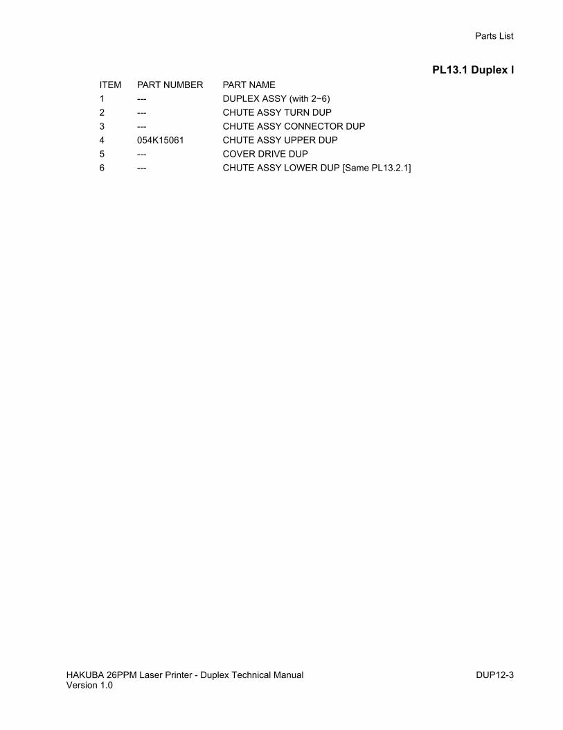
PL13.1 Duplex IITEM PART NUMBER PART NAME 1 --- DUPLEX ASSY (with 2~6)2 --- CHUTE ASSY TURN DUP3 --- CHUTE ASSY CONNECTOR DUP4 054K15061 CHUTE ASSY UPPER DUP5 --- COVER DRIVE DUP6 --- CHUTE ASSY LOWER DUP [Same PL13.2.1]

DUP12-4 HAKUBA 26PPM Laser Printer - Duplex Technical ManualVersion 1.0
Parts List
PL13.2 Duplex II

HAKUBA 26PPM Laser Printer - Duplex Technical Manual DUP12-5Version 1.0
Parts List
PL13.2 Duplex IIITEM PART NUMBER PART NAME1 --- CHUTE ASSY LOWER DUP (with 2~19) [Same PL13.1.6]2 059K12151 ROLL ASSY DUP3 003E47580 STOPPER BELT DUP4 --- GEAR DUP 17/PULLEY5 --- BEARING DUP6 --- GEAR DUP 187 --- GEAR DUP 17/398 127K36520 MOTOR ASSY DUP9 423W15455 BELT SYNCHRONOUS10 --- CHUTE LOWER DUP11 --- LATCH DUP12 --- SPRING LATCH DUP13 --- HARNESS ASSY DUP SNR (J36-J361)14 130E81970 SENSOR PHOTO IN-H (L)15 ---16 160K53051 PWBA DUP17 --- COVER DUP18 130K83310 SENSOR ASSY DUP19 --- LABLE HANDLE DUP

DUP12-6 HAKUBA 26PPM Laser Printer - Duplex Technical ManualVersion 1.0
Parts List

HAKUBA 26PPM Laser Printer - Offset Catch Tray Technical Manual OCT12-1Version 1.0
Parts List
Section 12 - Parts List Contents
PL14.1 Offset Catch Tray I . . . . . . . . . . . . . . . . . . . . . . . . . . . . . . . . . . . . . . . . . . . . . . . . . . . . . . . . 12-2PL14.2 Offset Catch Tray II . . . . . . . . . . . . . . . . . . . . . . . . . . . . . . . . . . . . . . . . . . . . . . . . . . . . . . . 12-4
Using the Parts List1. The numbers shown in each illustration correspond to the parts list number for that illustration. 2. Throughout this manual, parts are identified by the prefix “PL”, followed by a number, a decimal point,
and another number. For example, PL3.1.12 means the part is item 12 of parts list 3.1.3. The capital letters “C”, “E”, and “S” shown in an illustration stand for C-ring, E-ring, and Screw, respec-
tively.4. A shaded triangle t in an illustration indicates the item is part of an assembly.5. The notation “with X~Y” following an part name indicates an assembly that is made up of components
X through Y. For example, “1 (with 2~4)” means part 1 consists of part 2, part 3, and part 4.6. The notation "RS" means that the part is a requested spare. Part numbers for these parts will be pro-
vided as soon as they are available.7. An asterisk * following a part name indicates the page contains a note about this part.8. The notation “J1<>J2 and P2” is attached to a wire harness. It indicates that connector jack 1 is
attached to one end of the wire harness and connector jack 2 is attached to the other end that isplugged into plug 2.
9. A notation "(part of item 1.1)" indicates that the part is included with item 1.2.1 (PL1.2, line item 1).

OCT12-2 HAKUBA 26PPM Laser Printer - Offset Catch Tray Technical ManualVersion 1.0
Parts List
PL14.1 Offset Catch Tray I

HAKUBA 26PPM Laser Printer - Offset Catch Tray Technical Manual OCT12-3Version 1.0
Parts List
PL14.1 Offset Catch Tray IITEM PART NAME
1 --- OFFSET CATCH TRAY ASSY (with 2~17)2 050K38631 TRAY EXIT ASSY3 --- SPRING TRAY4 050E89160 TRAY EXIT5 ---6 012E09551 LINK WEIGHT7 802E02773 COVER REAR8 ---9 ---10 ---11 802E02755 COVER OCT12 054K22380 CHUTE EXIT INNER ASSY [Same PL14.2.1]13 --- HOOK COVER14 --- COVER LOWER15 --- HINGE COVER16 --- SPRING COVER L17 --- SPRING COVER R

OCT12-4 HAKUBA 26PPM Laser Printer - Offset Catch Tray Technical ManualVersion 1.0
Parts List
PL14.2 Offset Catch Tray II

HAKUBA 26PPM Laser Printer - Offset Catch Tray Technical Manual OCT12-5Version 1.0
Parts List
PL14.2 Offset Catch Tray IIITEM PART NAME
1 054K22380 CHUTE EXIT INNER ASSY (with 2~45) [Same PL14.1.12]2 --- HARNESS ASSY OCT UNIT (J202-J209)3 --- HOLDER PWBA4 160K88240 PWBA OCT5 --- PLATE EARTH6 127K28640 MOTOR DRIVE ASSY7 --- GEAR EXIT 208 --- BEARING EXIT9 --- GEAR 2710 --- GEAR 2611 --- GEAR 47W12 --- GEAR EXIT13 --- ELIMINATOR14 --- HSG GEAR15 121K20551 SOLENOID DIRECTION16 011E09450 LEVER SOLENOID17 --- PIN SOLENOID18 130K84220 SENSOR ASSY EXIT OCT19 120E17191 ACTUATOR FULL STACK20 130E81970 SENSOR FULL STACK21 --- HARNESS ASSY OCT SNR (J224-225,J226,J227,J228)22 --- ROLL ASSY OFFSET (with 23~26,45)23 --- ROLL ASSY EXIT24 --- ROLL PINCH EXIT25 --- BEARING OFFSET26 --- GUIDE OCT27 --- HOLDER OCT28 --- SHAFT EXIT29 --- ROLL ASSY MID OCT30 --- ROLL PINCH OCT31 --- SPRING PINCH MID32 054E14431 CHUTE EXIT INNER33 ---34 802K05770 OFFSET ASSY (with 35~39)35 --- MOTOR OFFSET ASSY36 --- HSG OFFSET37 130E81970 SENSOR OCT HOME38 --- LEVER OFFSET39 --- GEAR CORE40 --- FERRITE CORE41 --- WIRE ASSY OCT42 ---43 --- BRACKET SENSOR44 --- EDGE SADDLE45 --- SPRING PINCH EXIT

OCT12-6 HAKUBA 26PPM Laser Printer - Offset Catch Tray Technical ManualVersion 1.0
Parts List

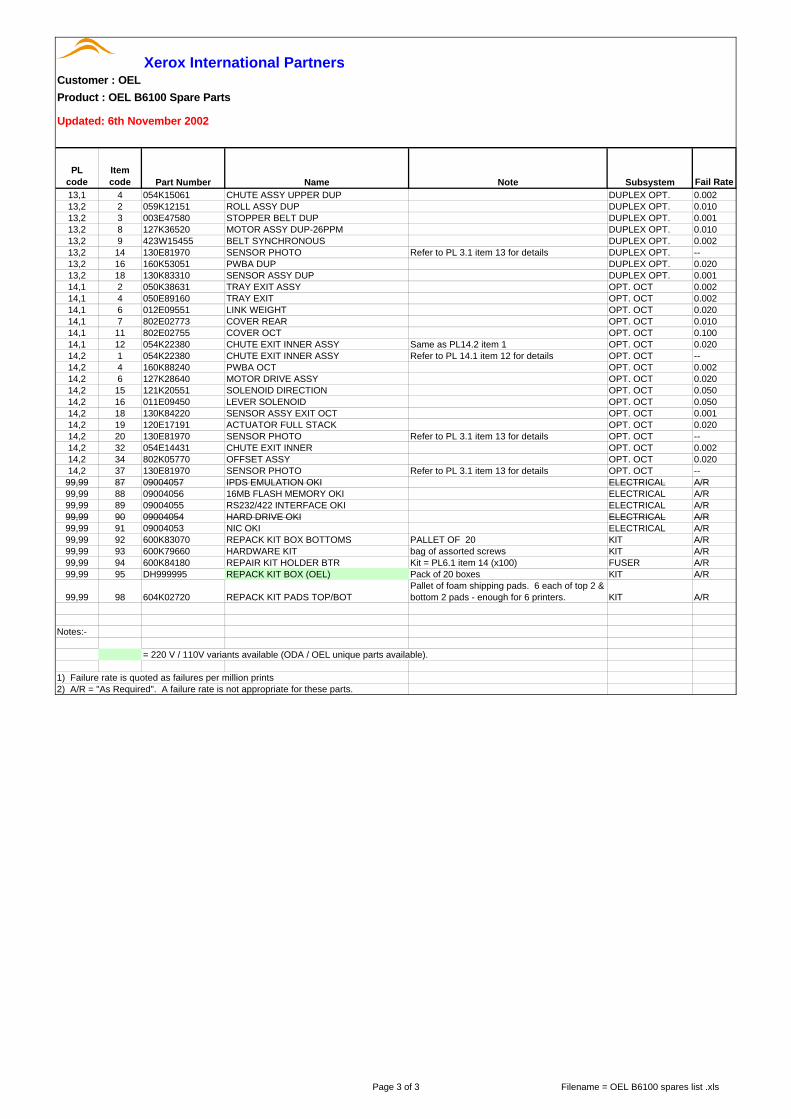
Xerox International PartnersCustomer : OEL
Product : OEL B6100 Spare Parts
Updated: 6th November 2002
PLcode
Itemcode Part Number Name Note Subsystem Fail Rate
1,1 1 048E64591 COVER LEFT COVERS 0,0011,1 2 048K76270 COVER ASSY I/F COVERS 0,0011,1 4 048E64642 COVER OPTION COVERS 0,0011,1 5 048K76455 COVER ASSY TOP With PL1.1 item 23 COVERS 0,0011,1 6 802K51410 CONTROL ASSY PANEL (OEL) With PL1.1 item 7 ELECTRICAL 0.0101,1 7 162K43680 HARNESS ASSY PANEL ELECTRICAL 0.0011,1 8 048E64612 COVER RIGHT COVERS 0.0011,1 9 048K76243 COVER ASSY FRONT With PL1.1 items 10-13, 15-17, 20-22 & 26 COVERS 0.0051,1 14 003E48991 STOPPER COVER COVERS 0.0101,1 16 003E43880 STOPPER TRAY COVERS 0.0501,1 17 050K37121 TRAY ASSY MBF MSI 0.0501,1 19 048E64624 COVER ASSY L/H No Logo, same as Genicom's EU version MSI 0.0011,1 19 802E49470 COVER ASSY L/H OEL MSI 0.0011,1 22 354W24254 KL CLIP COVERS 0.0011,1 26 004K01870 CLEANING PAD ASSY MSI A/R1,2 10 003E46120 STOPPER COVERS 0.0101,2 98 600K79530 KIT CAP ENVELOPE ICE GREEN Kit = PL1.2 item 7 (x2) COVERS 0.1001,2 99 802K12743 COVER ASSY REAR With PL1.2 items 1-9 COVERS 0.1002,1 5 604K04810 KIT GUIDE END CST 0.0032,2 7 005K82890 CLUTCH ASSY FRICTION CST 0.1002,2 10 809E11830 SPRING RETARD CST 0.0022,2 22 127K24682 MOTOR ASSY CST 0.0502,2 25 114E11680 CONNECTOR CST 0.001
2,2 99 600K79550 KIT ROLL FEEDSame as PL3.1 item 99 & PL11.2 item 99.Kit = PL2.2 item 8 & PL3.1 item 26 (x2) FEEDER A/R
3,1 1 022K51531 ROLL ASSY TURN 1 FEEDER 0.0203,1 2 121K20151 CLUTCH ASSY TURN Same as PL11.2 item 3 FEEDER 0.1003,1 4 809E11630 SPRING CHUTE Same as PL11.2 item 5 FEEDER 0.0013,1 6 120E16960 ACTUATOR N/P Same as PL11.2 item 6 FEEDER 0.0503,1 7 830E18132 SUPPORT ACTUATOR Same as PL11.2 item 7 FEEDER 0.001
3,1 13 130E81970 SENSOR PHOTO
Same as PL4.1 item 19, PL5.1 item 12, PL7.1 item 16, PL11.2 item 13, PL12.2 item 22, PL13.2 item 14, PL14.2 item 20 & PL14.2 item 37 FEEDER 0.001
3,1 14 162K47211 HARNESS ASSY N/SNSR Same as PL11.2 item 14 FEEDER 0.0013,1 19 600K79320 FEEDER ASSY FEEDER 0.1003,1 36 160K52781 PWBA FEEDER Same as PL11.2 item 36 FEEDER 0.0023,1 37 121K19010 CLUTCH ASSY FEED Same as PL11.2 item 37 FEEDER 0.100
3,1 96 600K79640 KIT SOCKET & HARNESSKit = PL3.1 items 39 & 40Same as PL11.2 item 96 FEEDER 0.002
3,1 97 600K79652 KIT ACTUATOR & SUPPORTKit = PL3.1 items 11, 12 & 18Same as PL11.2 item 97 FEEDER 0.050
3,1 98 022K56902 KIT FEEDER ASSY 1Kit = PL3.1 items 1-44Same as PL11.2 item 98 FEEDER 0.600
3,1 99 600K79550 KIT ROLL FEED Refer to PL 2.2 Item 99 for details FEEDER --4,1 1 054K22391 CHUTE MBF ASSY With PL4.1 items 2-31 MSI 0.5004,1 6 022K50815 ROLL ASSY MBF MSI 0.1004,1 12 120E17121 ACTUATOR N/P MBF MSI 0.0504,1 15 019K94573 PAD ASSY RETARD MSI 0.0504,1 19 130E81970 SENSOR PHOTO Refer to PL 3.1 item 13 for details MSI --4,1 23 121E85920 SOLENOID PICK UP MSI 0.0504,1 24 809E20171 SPRING MBF MSI 0.0014,1 25 007E54661 GEAR PICK UP MSI 0.0054,1 27 113K82141 CONNECTOR ASSY ENV MSI 0.0054,1 29 162K47021 HARNESS ASSY MBF N/P MSI 0.0014,1 31 019K96831 PAD PICK UP ASSY MSI 0.0505,1 4 054K14985 P/H ASSY With PL5.1 items 2, 5-31, 36-39 PAP XPORT 0.1005,1 7 059K11911 ROLL REGI RUBBER PAP XPORT 0.0025,1 10 120E13331 ACTUATOR REGI PAP XPORT 0.0205,1 11 809E19722 SPRING SENSOR REGI PAP XPORT 0.0015,1 12 130E81970 SENSOR PHOTO Refer to PL 3.1 item 13 for details PAP XPORT --5,1 14 809E22950 SPRING REGI R PAP XPORT 0.0015,1 15 007E54671 GEAR REGI METAL PAP XPORT 0.0015,1 16 007E54681 GEAR REGI RUBBER PAP XPORT 0.0015,1 19 121E85821 CLUTCH REGI PAP XPORT 0.1005,1 28 162K47011 HARNESS ASSY REGI PAP XPORT 0.0015,1 34 006E60981 SHAFT 14 PAP XPORT 0.0015,1 35 007E54650 GEAR 14 PAP XPORT 0.0015,1 36 809E19030 SPRING REGI L PAP XPORT 0.0015,1 99 600K79381 KIT TONER SENSOR With PL5.1 items 1-3, 32 & 33 XEROGRAPHICS 0.0506,1 2 022K55010 BTR ASSY XEROGRAPHICS 0.2006,1 3 054K15000 CHUTE TRANS ASSY With PL6.1 items 4-6, 13 PAP XPORT 0.0306,1 7 126K14941 FUSER ASSY 230V FUSER 5.006,1 12 962K06310 HARNESS ASSY FUSER-M 230V FUSER 0.0017,1 1 105K14904 ELIMINATOR EXIT EXIT 0.0027,1 2 120E13350 ACTUATOR FULL STACK EXIT 0.050
Page 1 of 3 Filename = OEL B6100 spares list .xls

Xerox International PartnersCustomer : OEL
Product : OEL B6100 Spare Parts
Updated: 6th November 2002
PLcode
Itemcode Part Number Name Note Subsystem Fail Rate
7,1 7 059K11950 ROLL ASSY MID-1 EXIT 0.0207,1 11 059K11960 ROLL ASSY MID-2 EXIT 0.0207,1 16 130E81970 SENSOR PHOTO Refer to PL 3.1 item 13 for details EXIT --7,1 17 162K46981 HARNESS ASSY FS SNR EXIT 0.0017,1 21 127K35830 MOTOR ASSY EXIT EXIT 0.0207,1 98 600K79540 KIT BEARING Kit = PL7.1 item 6 (x6) EXIT 0.0057,1 99 054K22170 CHUTE EXIT ASSY With PL7.1 items 1-16, 19-25 EXIT 0.0508,1 1 675K00020 CRU OEL XEROGRAPHICS 0.08,1 4 032K94111 CRU TOP GUIDE ASSY With PL8.1 item 3 XEROGRAPHICS 0.0508,1 7 962K14480 HARNESS ASSY ROS/VDO XEROGRAPHICS 0.0018,1 9 062K11210 ROS ASSY XEROGRAPHICS 0.2008,1 13 007K87580 GEAR ASSY DRIVE DRIVE 0.0508,1 14 127K35701 MOTOR ASSY MAIN (N) DRIVE 0.1008,1 99 032K96660 KIT SENSOR CRU OKI With PL8.1 items 2, 5 & 6 XEROGRAPHICS 0.0029,1 7 127E13840 FAN ASSY ELECTRICAL 0.0209,1 13 162K47001 HARNESS ASSY FEEDER ELECTRICAL 0.0019,1 19 160K52771 PWBA SIZE 1 ELECTRICAL 0.0029,1 20 162K48420 HARNESS ASSY SIZE M Same as PL11.01.13 ELECTRICAL 0.0019,1 99 802K09970 KIT SIZE SENSOR 1 With PL9.1 items 13-16, 19-21 ELECTRICAL 0.05010,1 1 162K47201 HARNESS ASSY ESS ELECTRICAL 0.00110,1 2 160K91620 PWB ESS (CONTROLLER) ELECTRICAL 0.25010,1 3 101K39511 PANEL BACK ASSY OKI ELECTRICAL 0.00110,1 4 162K49271 HARNESS ASSY OCT-M ELECTRICAL 0.00110,1 7 110K08571 SWITCH ASSY I/L REAR ELECTRICAL 0.00510,1 9 162K46991 HARNESS ASSY DUP-M ELECTRICAL 0.00210,1 10 162K46942 HARNESS ASSY CONN ELECTRICAL 0.00110,1 11 160K52761 PWBA CONN ELECTRICAL 0.00210,1 12 110K08561 SWITCH ASSY I/L FRONT ELECTRICAL 0.00510,1 13 160K85653 PWBA HKB 26 MCU ELECTRICAL 0.25010,1 14 105K15402 PWB HKB 5VDC ELECTRICAL 0.05010,1 15 162K46972 HARNESS ASSY LVPS ELECTRICAL 0.00110,1 17 105K19860 PWBA LVPS 230V ELECTRICAL 0.18010,1 18 110E94430 MAIN SWITCH ELECTRICAL 0.00210,1 19 162K46962 HARNESS ASSY HVPS ELECTRICAL 0.00110,1 20 105K19750 PWBA HVPS ELECTRICAL 0.05010,1 99 DH100199 BLANKING PLATE ESS OKI ELECTRICAL 0.00111,1 3 007E54920 GEAR OPT 1 OPT. FEEDER 0.00111,1 5 162K48431 HARNESS ASSY SIZE OPTION OPT. FEEDER 0.00111,1 7 160K53061 PWBA SIZE OPTION OPT. FEEDER 0.00211,1 16 802E04931 HOUSING SIDE R OPT. FEEDER 0.02011,1 17 022K56912 FEEDER ASSY Same as PL11.2 item 1 OPT. FEEDER 0.60011,1 19 802E04920 HOUSING SIDE L OPT. FEEDER 0.02011,1 98 600K79670 KIT SCREW Kit = PL11.1 item 20 (x3) OPT. FEEDER A/R11,1 99 802K09980 HOUSING ASSY SIZE SENSOR 2 With PL11.1 items 5-7, 10-13 OPT. FEEDER 0.05011,2 1 022K56912 FEEDER ASSY Refer to PL 11.2 item 17 for details OPT. FEEDER --11,2 2 022K55001 ROLL ASSY TURN 2 OPT. FEEDER 0.00211,2 3 121K20151 CLUTCH ASSY TURN Refer to PL 3.1 item 2 for details OPT. FEEDER --11,2 5 809E11630 SPRING CHUTE Refer to PL 3.1 item 4 for details OPT. FEEDER --11,2 6 120E16960 ACTUATOR N/P Refer to PL 3.1 item 6 for details OPT. FEEDER --11,2 7 830E18132 SUPPORT ACTUATOR Refer to PL 3.1 item 7 for details OPT. FEEDER --11,2 13 130E81970 SENSOR PHOTO Refer to PL 3.1 item 13 for details OPT. FEEDER --11,2 14 162K47030 HARNESS ASSY N/SNSR Refer to PL 3.1 item 14 for details OPT. FEEDER --11,2 36 160K52781 PWBA FEEDER Refer to PL 3.1 item 36 for details OPT. FEEDER --11,2 37 121K19010 CLUTCH ASSY FEED Refer to PL 3.1 item 37 for details OPT. FEEDER --11,2 96 600K79640 KIT SOCKET & HARNESS Refer to PL 3.1 item 96 for details OPT. FEEDER --11,2 97 600K79652 KIT ACTUATOR & SUPPORT Refer to PL 3.1 item 97 for details OPT. FEEDER --11,2 98 022K56902 KIT FEEDER ASSY 1 Refer to PL 3.1 item 98 for details OPT. FEEDER --
11,2 99 600K79550 KIT ROLL FEEDRefer to PL 2.2 Item 99 for details.Kit = PL11.2 item 26 (x3). OPT. FEEDER --
12,1 2 054E14453 CHUTE TOP OPT. ENV. FDR 0.00212,1 11 031E93291 ARM WEIGHT OPT. ENV. FDR 0.20012,1 23 130K60390 SENSOR ASSY EXIT ENV OPT. ENV. FDR 0.00112,1 30 059E93940 ROLL PINCH OPT. ENV. FDR 0.01012,1 99 600K79310 KIT ROLL ASSY RETARD With PL12.1 items 3-8 OPT. ENV. FDR 0.00212,2 3 007E27420 GEAR 29 OPT. ENV. FDR 0.00112,2 5 007E36080 GEAR 23 OPT. ENV. FDR 0.00112,2 6 121K87180 CLUTCH ASSY TORQUE 25 OPT. ENV. FDR 0.10012,2 8 007E28780 GEAR IDLER 21 OPT. ENV. FDR 0.00112,2 9 121K87201 CLUTCH ASSY ONE WAY 26 OPT. ENV. FDR 0.10012,2 11 121K87190 CLUTCH ELEC 29 OPT. ENV. FDR 0.10012,2 12 006E47120 SHAFT CLUTCH ELEC 17 OPT. ENV. FDR 0.00112,2 13 121K87210 CLUTCH ASSY ONE WAY 26A OPT. ENV. FDR 0.10012,2 18 059E91910 ROLL PINCH ENV OPT. ENV. FDR 0.00212,2 22 130E81970 SENSOR PHOTO Refer to PL 3.1 item 13 for details OPT. ENV. FDR --12,2 23 059K13390 ROLL ASSY FEED 1 OPT. ENV. FDR 0.02012,2 25 059K13401 ROLL ASSY FEED 2 OPT. ENV. FDR 0.020
Page 2 of 3 Filename = OEL B6100 spares list .xls
Xerox International PartnersCustomer : OEL
Product : OEL B6100 Spare Parts
Updated: 6th November 2002
PLcode
Itemcode Part Number Name Note Subsystem Fail Rate
13,1 4 054K15061 CHUTE ASSY UPPER DUP DUPLEX OPT. 0.00213,2 2 059K12151 ROLL ASSY DUP DUPLEX OPT. 0.01013,2 3 003E47580 STOPPER BELT DUP DUPLEX OPT. 0.00113,2 8 127K36520 MOTOR ASSY DUP-26PPM DUPLEX OPT. 0.01013,2 9 423W15455 BELT SYNCHRONOUS DUPLEX OPT. 0.00213,2 14 130E81970 SENSOR PHOTO Refer to PL 3.1 item 13 for details DUPLEX OPT. --13,2 16 160K53051 PWBA DUP DUPLEX OPT. 0.02013,2 18 130K83310 SENSOR ASSY DUP DUPLEX OPT. 0.00114,1 2 050K38631 TRAY EXIT ASSY OPT. OCT 0.00214,1 4 050E89160 TRAY EXIT OPT. OCT 0.00214,1 6 012E09551 LINK WEIGHT OPT. OCT 0.02014,1 7 802E02773 COVER REAR OPT. OCT 0.01014,1 11 802E02755 COVER OCT OPT. OCT 0.10014,1 12 054K22380 CHUTE EXIT INNER ASSY Same as PL14.2 item 1 OPT. OCT 0.02014,2 1 054K22380 CHUTE EXIT INNER ASSY Refer to PL 14.1 item 12 for details OPT. OCT --14,2 4 160K88240 PWBA OCT OPT. OCT 0.00214,2 6 127K28640 MOTOR DRIVE ASSY OPT. OCT 0.02014,2 15 121K20551 SOLENOID DIRECTION OPT. OCT 0.05014,2 16 011E09450 LEVER SOLENOID OPT. OCT 0.05014,2 18 130K84220 SENSOR ASSY EXIT OCT OPT. OCT 0.00114,2 19 120E17191 ACTUATOR FULL STACK OPT. OCT 0.02014,2 20 130E81970 SENSOR PHOTO Refer to PL 3.1 item 13 for details OPT. OCT --14,2 32 054E14431 CHUTE EXIT INNER OPT. OCT 0.00214,2 34 802K05770 OFFSET ASSY OPT. OCT 0.02014,2 37 130E81970 SENSOR PHOTO Refer to PL 3.1 item 13 for details OPT. OCT --99,99 87 09004057 IPDS EMULATION OKI ELECTRICAL A/R99,99 88 09004056 16MB FLASH MEMORY OKI ELECTRICAL A/R99,99 89 09004055 RS232/422 INTERFACE OKI ELECTRICAL A/R99,99 90 09004054 HARD DRIVE OKI ELECTRICAL A/R99,99 91 09004053 NIC OKI ELECTRICAL A/R99,99 92 600K83070 REPACK KIT BOX BOTTOMS PALLET OF 20 KIT A/R99,99 93 600K79660 HARDWARE KIT bag of assorted screws KIT A/R99,99 94 600K84180 REPAIR KIT HOLDER BTR Kit = PL6.1 item 14 (x100) FUSER A/R99,99 95 DH999995 REPACK KIT BOX (OEL) Pack of 20 boxes KIT A/R
99,99 98 604K02720 REPACK KIT PADS TOP/BOTPallet of foam shipping pads. 6 each of top 2 & bottom 2 pads - enough for 6 printers. KIT A/R
Notes:-
= 220 V / 110V variants available (ODA / OEL unique parts available).
1) Failure rate is quoted as failures per million prints2) A/R = "As Required". A failure rate is not appropriate for these parts.
Page 3 of 3 Filename = OEL B6100 spares list .xls
Related Documents


