Greene County Design Standards - Adopted April 5, 1999 SECTION 111 - OPEN CHANNELS Greene County Design Standards - Adopted April 5, 1999. SECTION 111 - OPEN CHANNELS Page 1 of 14 SECTION 111 - OPEN CHANNELS 111.1 GENERAL DESIGN CONSIDERATIONS 111.2 GENERAL DESIGN REQUIREMENTS 111.2.1 Design Flow 111.2.2 Maximum Depth 111.2.3 Freeboard 111.2.4 Horizontal Alignment 111.2.5 Easements 111.2.6 Grades 111.2.7 Allowable Velocities 111.2.8 Utility Clearances 111.2.9 Plan Requirements 111.3 HYDRAULIC DESIGN 111.3.1 Uniform Flow 111.3.2 Gradually Varied Flow 111.3.3 Rapidly Varied Flow 111.4 DESIGN & CONSTRUCTION REQUIREMENTS 111.4.1 Natural Channels 111.4.2 Grass Channels 111.4.3 Low Flow (Trickle) Channels 111.4.4 Composite Channels 111.4.5 Concrete Channels 111.4.6 Riprap Linings 111.4.7 Other Types of Erosion Resistant Channel Linings 111.4.8 Drop Structures 111.5 ROADSIDE DITCHES 111.6 FLOODPLAIN REQUIREMENTS 111.7 REFERENCES Figure 111.1 Typical Natural Channel Figure 111.2 Typical Grass-Lined Channel Figure 111.3 Manning’s Roughness Coefficients for Grass-Lined Channels Figure 111.4 Concrete Trickle Channel Figure 111.5 Typical Grass-Lined Channel with Concrete Trickle Channel Figure 111.6 Typical Channel with Concrete Invert and Grass Side Slopes Figure 111.7 Trapezoidal Concrete Channel Figure 111.8 Rectangular Concrete Channel Figure 111.9 Typical Riprap Lined Channel Figure 111.10 Typical Roadside Ditches Table 111.1 Manning’s Roughness Coefficient for Various Channel Linings Table 111.2 Maximum Allowable Shear Stress for Various Lining Types

Welcome message from author
This document is posted to help you gain knowledge. Please leave a comment to let me know what you think about it! Share it to your friends and learn new things together.
Transcript
Greene County Design Standards - Adopted April 5, 1999
SECTION 111 - OPEN CHANNELS
Greene County Design Standards - Adopted April 5, 1999.
SECTION 111 - OPEN CHANNELS Page 1 of 14
SECTION 111 - OPEN CHANNELS
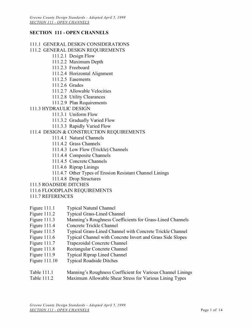
111.1 GENERAL DESIGN CONSIDERATIONS111.2 GENERAL DESIGN REQUIREMENTS
111.2.1 Design Flow111.2.2 Maximum Depth 111.2.3 Freeboard111.2.4 Horizontal Alignment111.2.5 Easements111.2.6 Grades111.2.7 Allowable Velocities111.2.8 Utility Clearances111.2.9 Plan Requirements
111.3 HYDRAULIC DESIGN111.3.1 Uniform Flow111.3.2 Gradually Varied Flow111.3.3 Rapidly Varied Flow
111.4 DESIGN & CONSTRUCTION REQUIREMENTS111.4.1 Natural Channels111.4.2 Grass Channels
111.4.3 Low Flow (Trickle) Channels111.4.4 Composite Channels111.4.5 Concrete Channels111.4.6 Riprap Linings111.4.7 Other Types of Erosion Resistant Channel Linings111.4.8 Drop Structures
111.5 ROADSIDE DITCHES111.6 FLOODPLAIN REQUIREMENTS111.7 REFERENCES
Figure 111.1 Typical Natural ChannelFigure 111.2 Typical Grass-Lined ChannelFigure 111.3 Manning’s Roughness Coefficients for Grass-Lined ChannelsFigure 111.4 Concrete Trickle ChannelFigure 111.5 Typical Grass-Lined Channel with Concrete Trickle ChannelFigure 111.6 Typical Channel with Concrete Invert and Grass Side SlopesFigure 111.7 Trapezoidal Concrete ChannelFigure 111.8 Rectangular Concrete ChannelFigure 111.9 Typical Riprap Lined ChannelFigure 111.10 Typical Roadside Ditches
Table 111.1 Manning’s Roughness Coefficient for Various Channel LiningsTable 111.2 Maximum Allowable Shear Stress for Various Lining Types

Greene County Design Standards - Adopted April 5, 1999
SECTION 111 - OPEN CHANNELS
Greene County Design Standards - Adopted April 5, 1999.
SECTION 111 - OPEN CHANNELS Page 2 of 14
SECTION 111 - OPEN CHANNELS
This section covers the evaluation of the capacity and stability of natural drainage channels, anddesign of constructed drainage channels, swales, and roadside ditches.
111.1 GENERAL DESIGN CONSIDERATIONS
Except for roadside ditches and swales, open channels are nearly always a component of themajor (emergency) drainage system. There are a number of factors which must be considered indetermining whether to specify an open drainageway as opposed to an underground storm drain:material and installation cost, maintenance costs and problems, acceptability to the developer orhome buyer, public safety, appearance, etc. Effective planning and design of open drainagewayscan significantly reduce the cost of storm drainage facilities, while enhancing the quality of thedevelopment.
In planning a subdivision, the designer should begin by determining the location and the width ofexisting drainageways. Streets and lots should be laid out in a manner to preserve the existingdrainage system to the greatest degree practical. In addition to reducing the cost of the drainagesystem, sediment and erosion control costs will also be reduced. Constructed channels should beused only when it is not practical or feasible to utilize existing drainageways.
111.2 GENERAL DESIGN REQUIREMENTS
111.2.1 Design Flow
Open channels shall be designed to convey the peak flow rate resulting from a storm having arainfall intensity corresponding to the time of concentration at the point of interest or a durationwhich produces the maximum runoff rate at the point of interest, depending upon the methodused for computing runoff. Open channels draining less than two hundred (200) acres can bedesigned for runoff rates computed by the Rational Method. The peak flow rate considered shallbe determined using fully urbanized conditions in the watershed. Effects of detention basins inreducing peak flow rates in the upstream watershed will be considered only if the detentionbasins are included in a hydrologic model used to estimate the peak flow rate and provided thedetention basins are located in permanent drainage easements.
The design storm frequency shall be as follows:
Total drainage area less than one (1) square mile: 25-year (4% AEP) stormTotal drainage area one (1) square mile or more: 100-year (1% AEP) storm
111.2.2 Maximum Depth
Unless otherwise approved due to unavoidable physical or right-of-way constraints, themaximum depth for the 25-year storm shall be three feet (3') in constructed channels.
Greene County Design Standards - Adopted April 5, 1999
SECTION 111 - OPEN CHANNELS
Greene County Design Standards - Adopted April 5, 1999.
SECTION 111 - OPEN CHANNELS Page 3 of 14
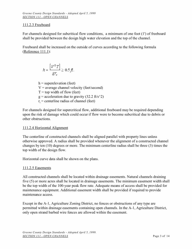
111.2.3 Freeboard
For channels designed for subcritical flow conditions, a minimum of one foot (1') of freeboardshall be provided between the design high water elevation and the top of the channel.
Freeboard shall be increased on the outside of curves according to the following formula(Reference 111.1):
h = superelevation (feet)V = average channel velocity (feet/second)T = top width of flow (feet)g = acceleration due to gravity (32.2 ft/s^2)rc = centerline radius of channel (feet)
For channels designed for supercritical flow, additional freeboard may be required dependingupon the risk of damage which could occur if flow were to become subcritical due to debris orother obstructions.
111.2.4 Horizontal Alignment
The centerline of constructed channels shall be aligned parallel with property lines unlessotherwise approved. A radius shall be provided whenever the alignment of a constructed channelchanges by ten (10) degrees or more. The minimum centerline radius shall be three (3) times thetop width of the design flow.
Horizontal curve data shall be shown on the plans.
111.2.5 Easements
All constructed channels shall be located within drainage easements. Natural channels drainingfive (5) or more acres shall be located in drainage easements. The minimum easement width shallbe the top width of the 100-year peak flow rate. Adequate means of access shall be provided formaintenance equipment. Additional easement width shall be provided if required to providemaintenance access.
Except in the A-1, Agriculture Zoning District, no fences or obstructions of any type arepermitted within drainage easements containing open channels. In the A-1, Agriculture District,only open strand barbed wire fences are allowed within the easement.
Greene County Design Standards - Adopted April 5, 1999
SECTION 111 - OPEN CHANNELS
Greene County Design Standards - Adopted April 5, 1999.
SECTION 111 - OPEN CHANNELS Page 4 of 14
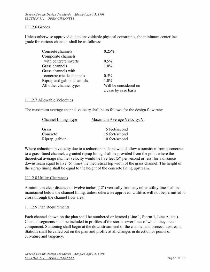
111.2.6 Grades
Unless otherwise approved due to unavoidable physical constraints, the minimum centerlinegrade for various channels shall be as follows:
Concrete channels 0.25%Composite channels with concrete inverts 0.5%Grass channels 1.0%Grass channels with concrete trickle channels 0.5%Riprap and gabion channels 1.0%All other channel types Will be considered on
a case by case basis
111.2.7 Allowable Velocities
The maximum average channel velocity shall be as follows for the design flow rate:
Channel Lining Type Maximum Average Velocity, V
Grass 5 feet/secondConcrete 15 feet/secondRiprap, gabion 10 feet/second
Where reduction in velocity due to a reduction in slope would allow a transition from a concreteto a grass-lined channel, a grouted riprap lining shall be provided from the point where thetheoretical average channel velocity would be five feet (5') per second or less, for a distancedownstream equal to five (5) times the theoretical top width of the grass channel. The height ofthe riprap lining shall be equal to the height of the concrete lining upstream.
111.2.8 Utility Clearances
A minimum clear distance of twelve inches (12") vertically from any other utility line shall bemaintained below the channel lining, unless otherwise approved. Utilities will not be permitted tocross through the channel flow area.
111.2.9 Plan Requirements
Each channel shown on the plan shall be numbered or lettered (Line 1, Storm 1, Line A, etc.).Channel segments shall be included in profiles of the storm sewer lines of which they are acomponent. Stationing shall begin at the downstream end of the channel and proceed upstream.Stations shall be called out on the plan and profile at all changes in direction or points ofcurvature and tangency.
Greene County Design Standards - Adopted April 5, 1999
SECTION 111 - OPEN CHANNELS
Greene County Design Standards - Adopted April 5, 1999.
SECTION 111 - OPEN CHANNELS Page 5 of 14
111.3 HYDRAULIC DESIGN
111.3.1 Uniform Flow
Open channels having a design flow rate less than five hundred (500) cfs may be designedassuming uniform flow conditions in conjunction with computed headwater depths at culvertsand other hydraulic structures or reservoir stages at detention and sediment basins. Water surfaceprofiles using techniques for gradually varied flow may be required for design flow rates lessthan five hundred (500) cfs where accurate determination flooding depths is necessary to ensureflood safety.
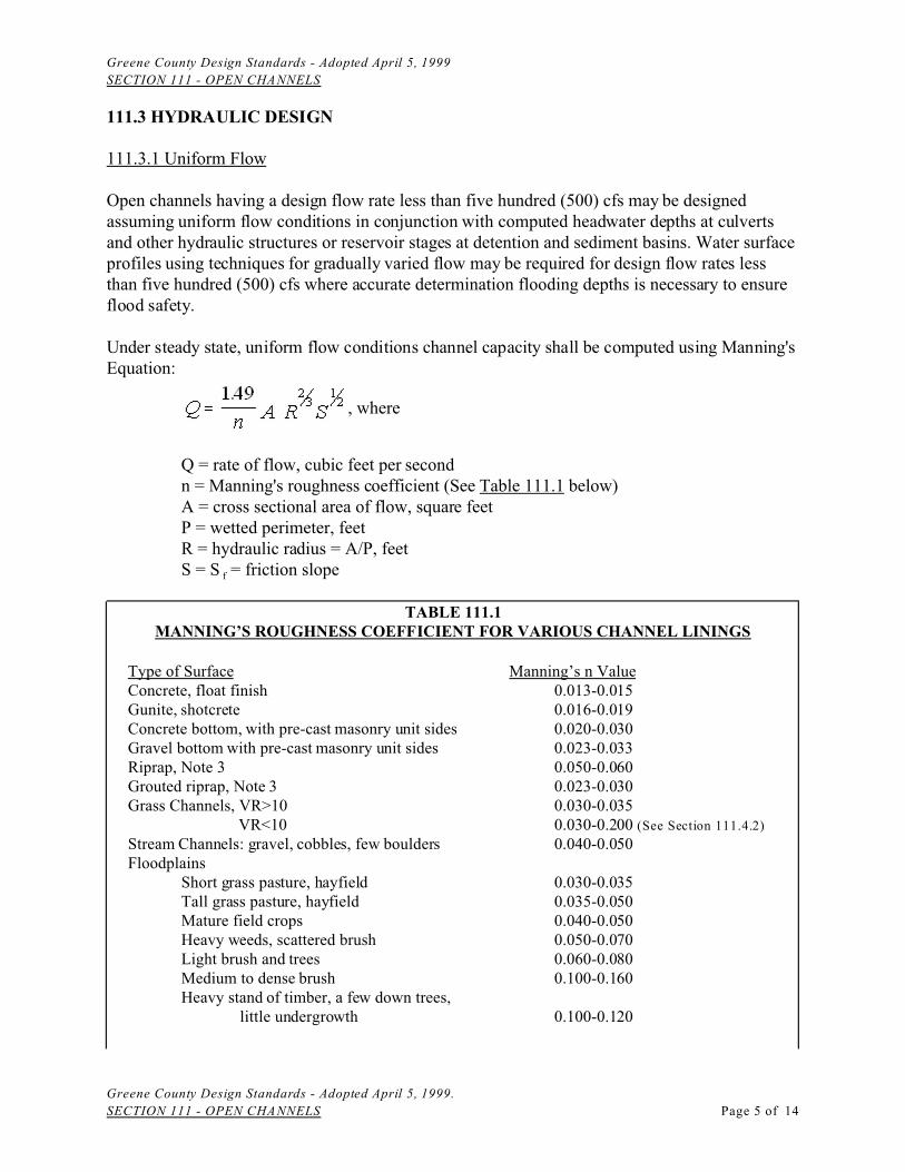
Under steady state, uniform flow conditions channel capacity shall be computed using Manning'sEquation:
, where
Q = rate of flow, cubic feet per secondn = Manning's roughness coefficient (See Table 111.1 below)A = cross sectional area of flow, square feetP = wetted perimeter, feetR = hydraulic radius = A/P, feetS = S f = friction slope
TABLE 111.1MANNING’S ROUGHNESS COEFFICIENT FOR VARIOUS CHANNEL LININGS
Type of Surface Manning’s n ValueConcrete, float finish 0.013-0.015Gunite, shotcrete 0.016-0.019Concrete bottom, with pre-cast masonry unit sides 0.020-0.030Gravel bottom with pre-cast masonry unit sides 0.023-0.033Riprap, Note 3 0.050-0.060Grouted riprap, Note 3 0.023-0.030Grass Channels, VR>10 0.030-0.035
VR<10 0.030-0.200 (See Section 111.4.2)
Stream Channels: gravel, cobbles, few boulders 0.040-0.050Floodplains
Short grass pasture, hayfield 0.030-0.035Tall grass pasture, hayfield 0.035-0.050Mature field crops 0.040-0.050Heavy weeds, scattered brush 0.050-0.070Light brush and trees 0.060-0.080Medium to dense brush 0.100-0.160Heavy stand of timber, a few down trees,
little undergrowth 0.100-0.120
Greene County Design Standards - Adopted April 5, 1999
SECTION 111 - OPEN CHANNELS
Greene County Design Standards - Adopted April 5, 1999.
SECTION 111 - OPEN CHANNELS Page 6 of 14
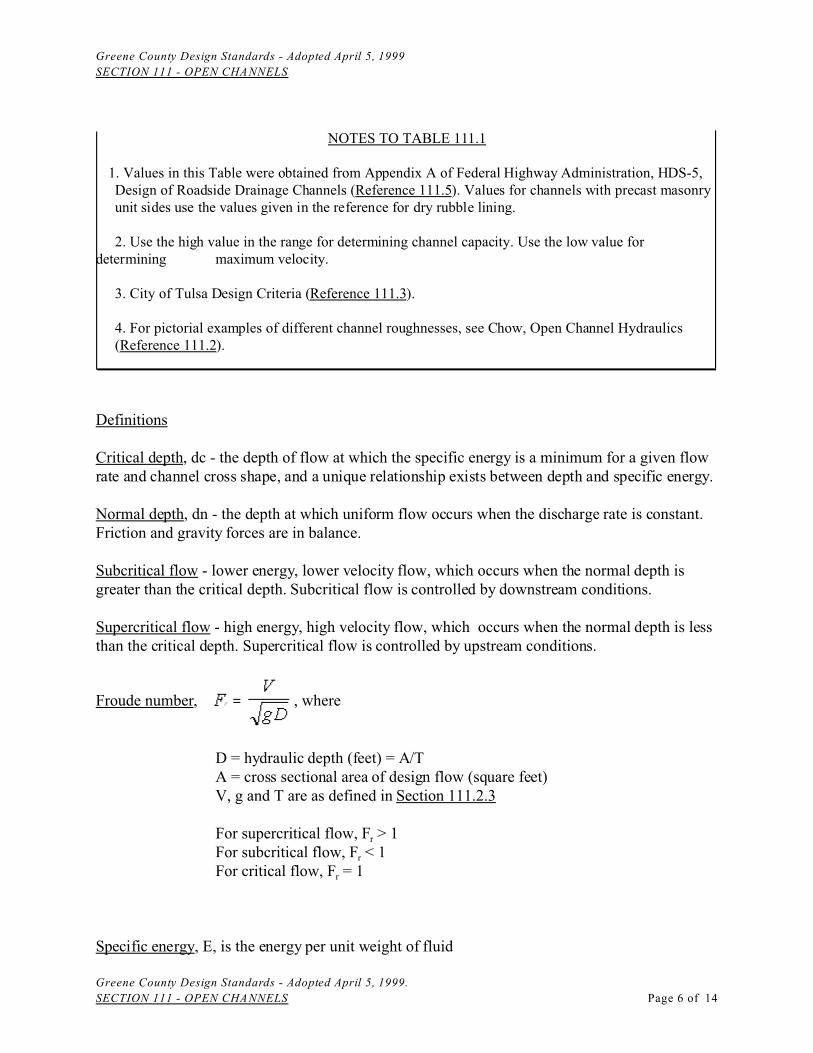
NOTES TO TABLE 111.1
1. Values in this Table were obtained from Appendix A of Federal Highway Administration, HDS-5, Design of Roadside Drainage Channels (Reference 111.5). Values for channels with precast masonryunit sides use the values given in the reference for dry rubble lining.
2. Use the high value in the range for determining channel capacity. Use the low value fordetermining maximum velocity.
3. City of Tulsa Design Criteria (Reference 111.3).
4. For pictorial examples of different channel roughnesses, see Chow, Open Channel Hydraulics (Reference 111.2).
Definitions
Critical depth, dc - the depth of flow at which the specific energy is a minimum for a given flowrate and channel cross shape, and a unique relationship exists between depth and specific energy.
Normal depth, dn - the depth at which uniform flow occurs when the discharge rate is constant.Friction and gravity forces are in balance.
Subcritical flow - lower energy, lower velocity flow, which occurs when the normal depth isgreater than the critical depth. Subcritical flow is controlled by downstream conditions.
Supercritical flow - high energy, high velocity flow, which occurs when the normal depth is lessthan the critical depth. Supercritical flow is controlled by upstream conditions.
Froude number, , where
D = hydraulic depth (feet) = A/TA = cross sectional area of design flow (square feet)V, g and T are as defined in Section 111.2.3
For supercritical flow, Fr > 1For subcritical flow, Fr < 1For critical flow, Fr = 1
Specific energy, E, is the energy per unit weight of fluid
Greene County Design Standards - Adopted April 5, 1999
SECTION 111 - OPEN CHANNELS
Greene County Design Standards - Adopted April 5, 1999.
SECTION 111 - OPEN CHANNELS Page 7 of 14
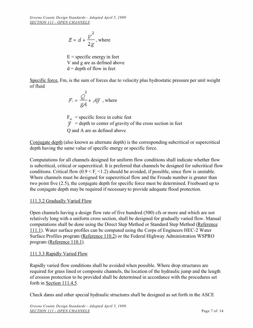
, where
E = specific energy in feetV and g are as defined aboved = depth of flow in feet
Specific force, Fm, is the sum of forces due to velocity plus hydrostatic pressure per unit weightof fluid
, where
Fm = specific force in cubic feet = depth to center of gravity of the cross section in feet
Q and A are as defined above
Conjugate depth (also known as alternate depth) is the corresponding subcritical or supercriticaldepth having the same value of specific energy or specific force.
Computations for all channels designed for uniform flow conditions shall indicate whether flowis subcritical, critical or supercritical. It is preferred that channels be designed for subcritical flow conditions. Critical flow (0.9 < Fr <1.2) should be avoided, if possible, since flow is unstable.Where channels must be designed for supercritical flow and the Froude number is greater thantwo point five (2.5), the conjugate depth for specific force must be determined. Freeboard up tothe conjugate depth may be required if necessary to provide adequate flood protection.
111.3.2 Gradually Varied Flow
Open channels having a design flow rate of five hundred (500) cfs or more and which are notrelatively long with a uniform cross section, shall be designed for gradually varied flow. Manualcomputations shall be done using the Direct Step Method or Standard Step Method (Reference111.1). Water surface profiles can be computed using the Corps of Engineers HEC-2 WaterSurface Profiles program (Reference 110.2) or the Federal Highway Administration WSPROprogram (Reference 110.1).
111.3.3 Rapidly Varied Flow
Rapidly varied flow conditions shall be avoided when possible. Where drop structures arerequired for grass lined or composite channels, the location of the hydraulic jump and the lengthof erosion protection to be provided shall be determined in accordance with the procedures setforth in Section 111.4.5.
Check dams and other special hydraulic structures shall be designed as set forth in the ASCE
Greene County Design Standards - Adopted April 5, 1999
SECTION 111 - OPEN CHANNELS
Greene County Design Standards - Adopted April 5, 1999.
SECTION 111 - OPEN CHANNELS Page 8 of 14
Design Manual (Reference 111.1)
111.4 DESIGN & CONSTRUCTION REQUIREMENTS
111.4.1 Natural Channels
Perennial Streams and Losing Streams
The stream channel of perennially flowing streams or intermittent streams classified as losingstreams in the Missouri Clean Water Laws shall not be modified or channelized except whereunavoidable to construct road crossings or to repair erosion and stabilize the stream channel.
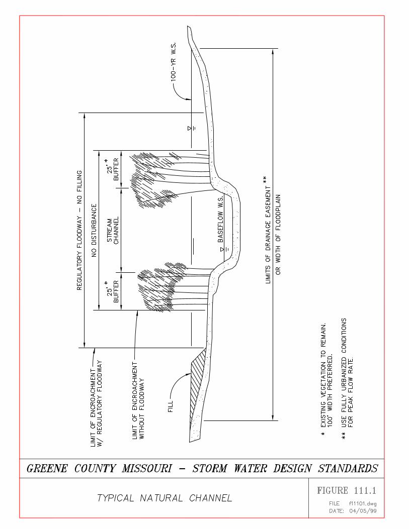
Trees and vegetation shall not be removed within twenty-five feet (25') of the stream bank.Clearing of brush and undergrowth shall be minimal. It is preferred that existing vegetationremain within one hundred feet (100') of the stream bank.
Any work within a Federally designated floodplain requires a Floodplain Development Permit. A Conditional Letter of Map Revision (CLOMR) must be obtained for any filling within thefloodway. Work within the stream channel may require a Department of the Army "404" permit.
Tributary Watercourses
Intermittent streams which have a defined channel should not be modified or channelized exceptwhere unavoidable for road crossings or to repair erosion and stabilize the stream channel. Noclearing is permitted within twenty-five feet (25') of the stream bank except to removeunderbrush and fallen timber.
Natural watercourses in which flow is broad and shallow, and which have no defined channelshould not be modified or channelized. Removal of trees and vegetation within the watercourseshould be avoided as much as practical.
Determining Flooding Limits for Watercourses
The area inundated by the peak flow from the 100-year (1% AEP) storm is considered to be theflooding area for any watercourse, whether or not it is designated on the Flood Insurance RateMaps for Greene County. An implicit drainage easement is considered to exist along the areainundated by the peak flow from the 1% AEP (100-year) storm.
For the purpose of preliminary planning and design, the approximate limits of the floodplain canbe determined using approximate methods.
In determining the capacity and depth of flow in natural watercourses, they shall be analyzed byselecting the most restrictive channel section for each reach and determining the normal depth byanalyzing the channel as an irregular section using representative "n" values for each segment ofthe channel cross-section.
Greene County Design Standards - Adopted April 5, 1999
SECTION 111 - OPEN CHANNELS
Greene County Design Standards - Adopted April 5, 1999.
SECTION 111 - OPEN CHANNELS Page 9 of 14
Development Guidelines
Where the width of the existing drainageway cannot accommodate the needs of the development,the fringe areas of the drainageway can be filled, and tributary watercourses may be channelizedwithin the limitations described above. The combination of filling and channeling shall notincrease the estimated high water elevation for the 100-year (1% AEP) peak flow rate by morethan one foot (1') over pre-project conditions at the upstream boundary or any point upstream ofthe site.
Where the effects of increased frequency of flow or increased velocity may significantly effectthe stability or the stream channel, measures such as grade checks, check dams or bankstabilization may be required.
A typical natural channel cross section is shown in Figure 111.1.
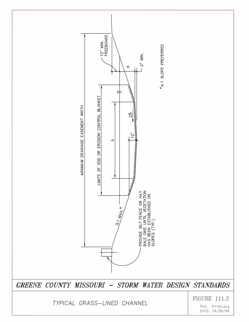
111.4.2 Grass Channels
Grass lined channels shall have a minimum slope of 1% (one percent). The bottom slope may bedecreased to 0.5% (five-tenths percent) if a concrete trickle channel is provided.
Maximum side slopes shall be 3:1, with 4:1 preferred.
In order to establish growth in the channel bottom, the bottom twelve inches (12") of the channeldepth shall be lined with sod, or suitable erosion control blanket.
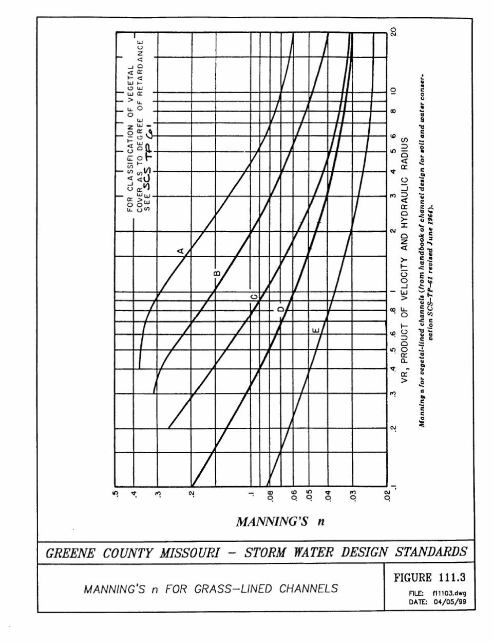
A typical grass lined channel cross section is shown in Figure 111.2. Manning's roughness coefficient ("n", also known as the retardance coefficient) for grasschannels shall be determined based upon the product of the velocity and the hydraulic radius (V xR) using the chart shown in Figure 111.3 (Reference 111.7). Retardance curve "C" shall be usedin determining channel capacity. Retardance curve "D" shall be used in determining velocity.
111.4.3 Low Flow (Trickle) Channels
Trickle channels shall be provided in constructed grass channels (not natural channels) wherebase flow or perennial flow prevents the establishment or re-establishment of a sod bottom.Types of trickle channels are as follows:
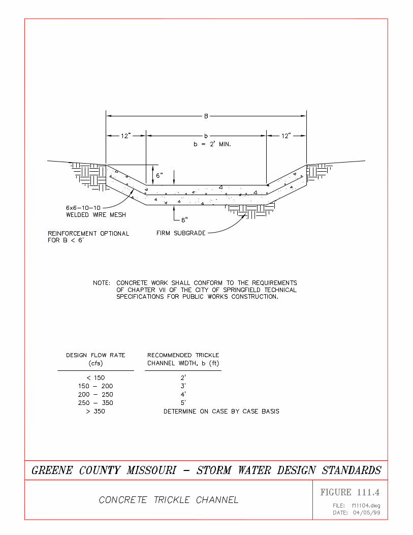
A. Concrete Trickle Channels
Trickle channel capacity shall be approximately five percent (5%) of the design flow rate. Astandard concrete trickle channel cross-section is shown in Figure 111.4. Other shapes may beused, provided capacity calculations are submitted and construction details are provided on theplans.
Concrete trickle channels may be unreinforced up to a total width of five feet (5'). For total
Greene County Design Standards - Adopted April 5, 1999
SECTION 111 - OPEN CHANNELS
Greene County Design Standards - Adopted April 5, 1999.
SECTION 111 - OPEN CHANNELS Page 10 of 14
widths of five feet (5') to ten feet (10'), the trickle channel shall be reinforced with 6 X 6-10-10welded wire mesh. For widths greater than ten feet (10'), see requirements for concrete channels.
Trickle channel alignment shall be the same as the overall channel alignment. Radii at changes indirection shall be the minimum radius required based upon the channel top width.
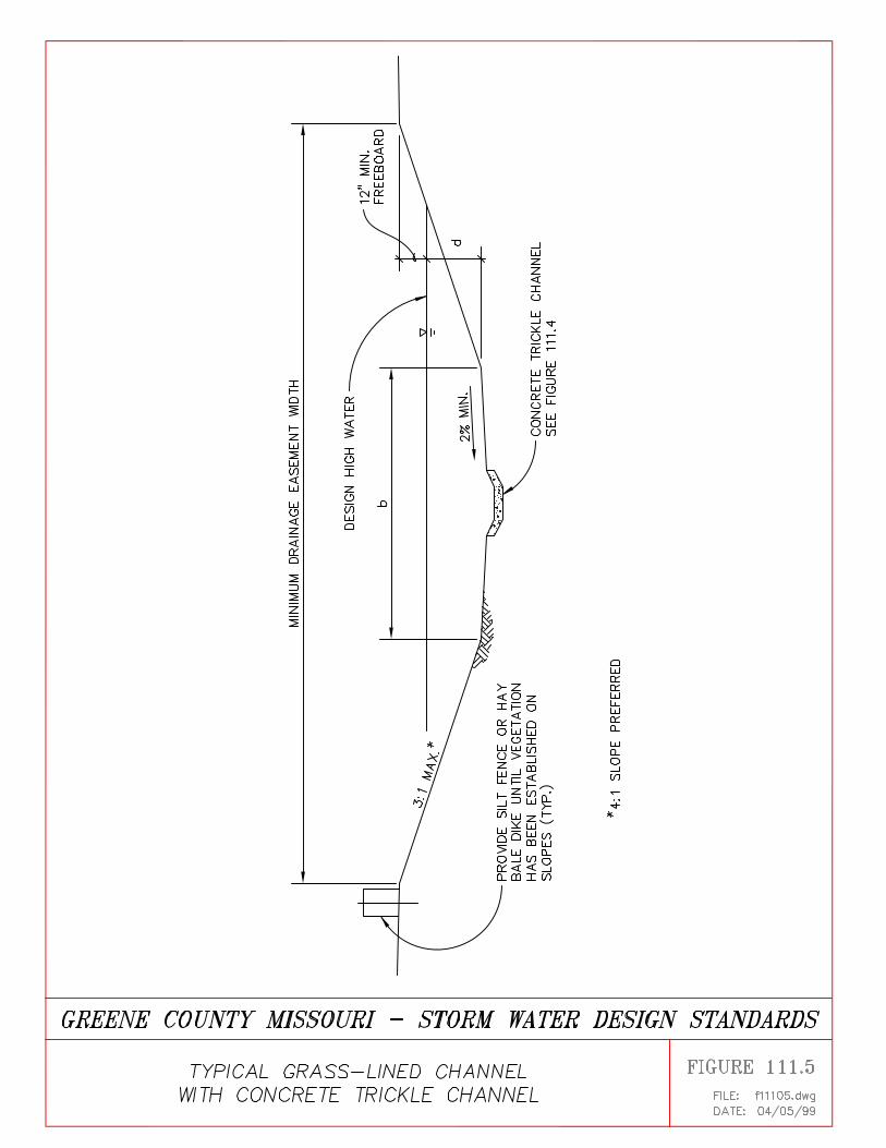
Capacity of grass channels with trickle channels may be determined as a composite cross-sectionin accordance with Section 111.4.3 , or the additional capacity of the trickle channel can beignored.
A typical cross section of a grass channel with a concrete trickle channel is shown in Figure111.5.
Erosion potential at the grass/concrete interface should be checked. Shear stress or tractive forceshall be determined as follows and shall be limited to the maximum values set forth below:
Shear force, , where
= unit shear stress (pounds per square foot)
= unit weight of water = 62.4 pounds per cubic foots = channel slope (feet per foot)d = distance from the water surface to the channel lining at the point of interest (feet)
TABLE 111.2
Maximum Allowable Shear Stress for Various Lining Types
Lining Type Maximum Shear Stress
Grass, sod 0.60 psfJute fiber net 0.40 psfStraw erosion control blanket
with attached netting 1.45 psfExcelsior (wood fiber) erosion
control blanket with netting 1.55 psfSynthetic erosion control blanket 2.00 psf
The foregoing values were obtained from Table 9.5 of the ASCE Design Manual (Reference111.1) Manufacturer's data shall be submitted for erosion control blankets specified.
B. Other Types of Trickle Channels
Trickle channels of porous pavers, gravel filled Geoweb, submerged flow wetlands, natural stoneand other materials can be specified, and are encouraged to improve aesthetics and water quality.However, assurance must be given that quality control will be maintained during construction
Greene County Design Standards - Adopted April 5, 1999
SECTION 111 - OPEN CHANNELS
Greene County Design Standards - Adopted April 5, 1999.
SECTION 111 - OPEN CHANNELS Page 11 of 14
and that adequate maintenance will be provided after construction.
Complete computations and construction specifications must be submitted for alternative typesof trickle channel linings.
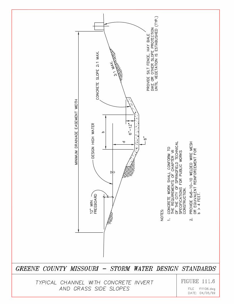
111.4.4 Composite Channels
Many different channel shapes and lining types are possible. Different shapes and lining typescan be combined in a composite design. In determining the capacity and depth of flow incomposite channels, they shall be analyzed as an irregular section using representative "n" valuesfor each segment of the channel cross-section. Velocity limitations set forth above shall beadhered to for each lining type. Allowable shear stress at the interface between grass or othererodible linings and erosion resistant linings may not exceed the maximum values set forth inTable 111.4.3.
A typical cross section of a channel with a concrete invert and grass slopes is shown in Figure111.6.
111.4.5 Concrete Channels
Where velocities or slopes cannot be limited to values required for natural, grass, or compositechannels due to right-of-way or other constraints, concrete channels may be utilized. Concretechannel shapes will typically be trapezoidal or rectangular. Other shapes may be used, but areless efficient.
Crushed rock bedding and pore pressure relief are required whenever the lining height exceedstwelve inches (12"). Whenever the concrete channel bottom is wide enough to accommodateconstruction or maintenance equipment (generally eight feet (8') wide or more), it shall bedesigned to carry an HS-20 leading and shall be reinforced. Welded wire mesh or steelreinforcing bars shall may by used.
Concrete channels shall be designed for subcritical flow where possible. Where flow issupercritical, the conjugate depth must be checked and additional freeboard may be required asprovided in Section 111.2.3.
Where slopes must be decreased to provide stability or maintain subcritical flow, drop structuresshould be provided.
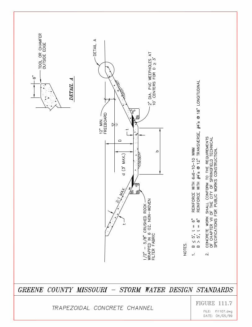
Trapezoidal Concrete Channels
Maximum side slopes shall be 2:1. Total channel depth is limited to three feet (3') unlessotherwise approved. For depths greater than twelve inches (12"), the channel slopes shall bereinforced with 6 X 6-10-10 welded wire mesh. A typical trapezoidal concrete channel section isshown in Figure 111.7.
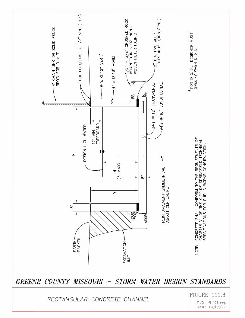
Rectangular Concrete Channels
Greene County Design Standards - Adopted April 5, 1999
SECTION 111 - OPEN CHANNELS
Greene County Design Standards - Adopted April 5, 1999.
SECTION 111 - OPEN CHANNELS Page 12 of 14
Vertical side walls shall be reinforced to withstand earth pressure and other anticipated loads.Design for hydrostatic pressure is not required if weep holes are provided for relief.A typical rectangular concrete channel section is shown in Figure 111.8.
A toe wall extending a minimum of eighteen inches (18") below grade shall be provided at thedownstream end of any concrete channel section, and should be provided at maximum intervalsof about one hundred feet (100') along the channel.
111.4.6 Riprap Linings
The use of riprap for channel linings is discouraged primarily due to poor construction practice.Because of the amount of labor required to properly place and chink stones into a stable mass,loose riprap is seldom stable. Further, gradations of stone tend to be highly variable and poorlycontrolled.
Loose riprap is susceptible to silting in, encouraging growth of weeds and vegetation, andcreating a maintenance and appearance problem. These problems can be overcome somewhat bygrouting the riprap; however, construction practice for grouted riprap is equally poor resulting ina highly variable penetration by the grout.
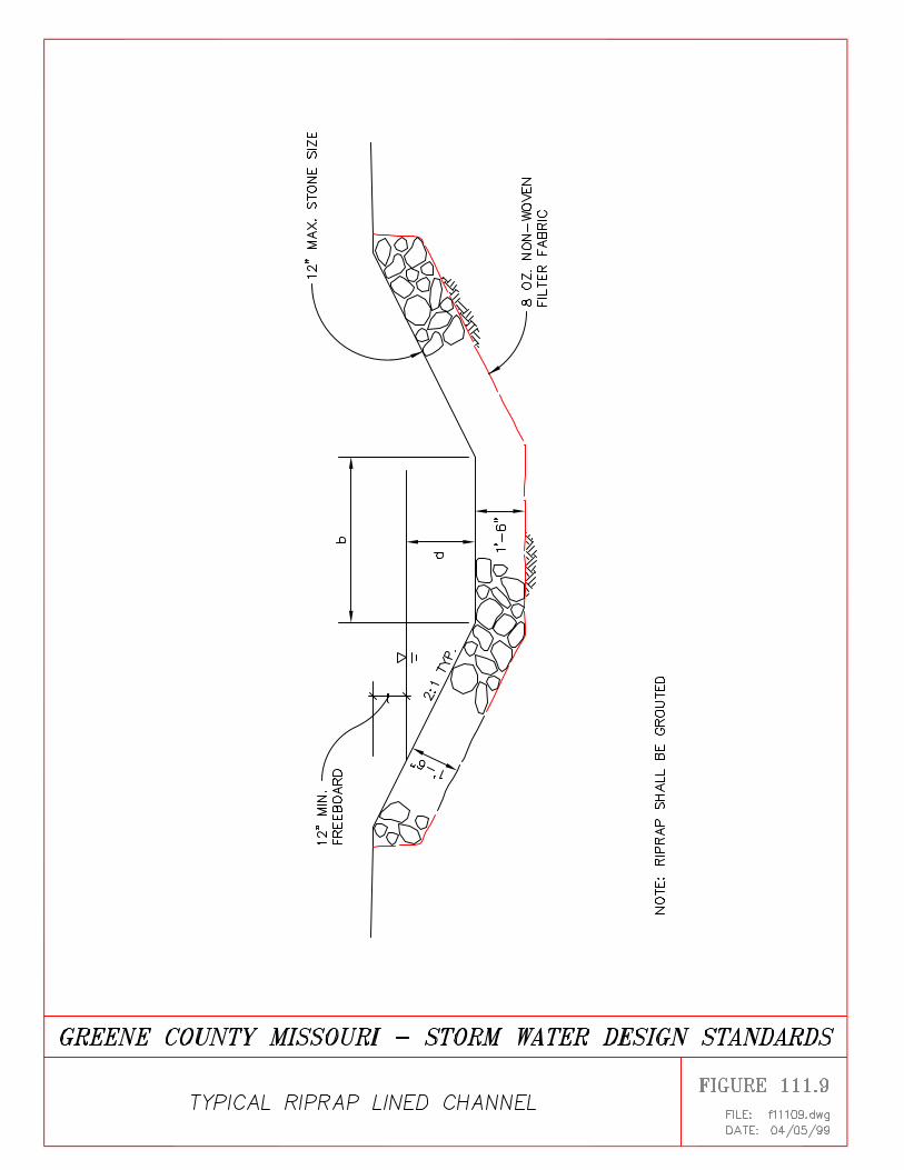
Riprap linings are best specified for only short distances in zones where erosion potential is high.Where riprap is specified it should be grouted to minimize maintenance problems, unless theinstallation is temporary. The maximum stone size should be twelve inches (12"). The riprapshall be laid over a non-woven filter fabric in order to prevent undercutting of the subgrade.
A typical riprap lining is shown in Figure 111.9.
111.4.7 Other Types of Erosion Resistant Channel Linings
Designers are encouraged to use other types of linings in order to reduce cost and improveappearance of drainage channels. Invert lining materials include concrete, reno mattresses, gravelfilled Geoweb, Geoweb filled with lean concrete, etc.
Sidewall lining materials include gabions, and precast concrete units, such as Keystone blocks,Loffelstein units, Windsor stone, and many other types of precast units.
In specifying any type of these linings, the manufacturer's installation instructions shall be strictlyfollowed.
111.4.8 Drop Structures
Where the channel slope must be decreased to provide stability, maintain subcritical flow, orreduce velocity to acceptable levels, drop structures may be provided. Grass lined channels shallbe provided with erosion resistant linings downstream to the point at which the average channelvelocity has returned to the allowable rate for the type of channel lining provided. Drop
Greene County Design Standards - Adopted April 5, 1999
SECTION 111 - OPEN CHANNELS
Greene County Design Standards - Adopted April 5, 1999.
SECTION 111 - OPEN CHANNELS Page 13 of 14
structures for vertical wall channels shall be designed in accordance with the ASCE DesignManual (Reference 111.1) or the U.S. Bureau of Reclamation Design of Small Canal Structures(Reference 111.4). Drop structures for trapezoidal channels shall be designed in accordance withthe City of Tulsa Design Criteria (Reference 111.3) or King's Handbook of Hydraulics(Reference 111.8).
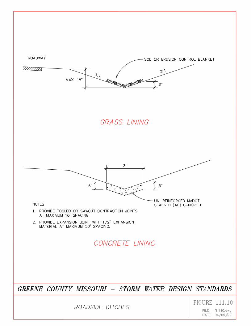
111.5 ROADSIDE DITCHES
Roadside ditches shall be designed for a maximum depth of two feet (2') measured from theroadway shoulder, and maximum 3:1 side slopes. Roadside ditches shall be grass lined and shallconform to the same velocity requirements as grass lined channels. The bottom six inches (6") ofthe ditch depth shall be lined with sod or erosion control blanket, or the developer must assumemaintenance responsibility for the ditch until growth is firmly established. A security agreementor performance bond will be required during the maintenance period.
Where the full flow velocity in the ditch exceeds five feet (5') per second, a concrete ditch lineras shown in Figure 111.10 shall be provided.
111.6 FLOODPLAIN REQUIREMENTS
Design of channels within floodplains shown on the Flood Insurance Rate Maps for GreeneCounty must be done in accordance with requirements of Article XIX, Floodplain ManagementOrdinance of the Greene County Zoning Regulations.
111.7 REFERENCES
1. American Society of Civil Engineers Manuals and Reports of Engineering Practice No. 77(WEF Manual of Practice FD-20), Design and Construction of Urban Stormwater ManagementSystems, Chapters 6 and 8. American Society of Civil Engineers, New York, NY, 1992.
2. Chow, V.T. Open Channel Hydraulics. McGraw-Hill Book Company, 1959.
3. City of Tulsa, Storm Drainage Criteria Manual, Department of Stormwater Management,Tulsa, OK, 1991.
4. U.S. Bureau of Reclamation, Design of Small Canal Structures, USBR Water ResourcesTechnical Publication, Washington, D. C., 1974.
5. U.S. Department of Transportation, Design of Roadside Drainage Channels, Hydraulic DesignSeries No. 4 (HDS-4) Federal Highway Administration, Washington, D.C., 1983.
6. U.S. Department of Transportation, Design of Stable Channels with Flexible Linings,Hydraulic Engineering Circular No. 15 (HEC-15)< Federal Highway Administration,Washington, D.C., 1975.
7. U. S. Soil Conservation Service, Handbook of Channel Design for Soil and Water
Greene County Design Standards - Adopted April 5, 1999
SECTION 111 - OPEN CHANNELS
Greene County Design Standards - Adopted April 5, 1999.
SECTION 111 - OPEN CHANNELS Page 14 of 14
Conservation. Publications No. SCS-TP-61, U.S. Government Printing Office, Washington,D.C., 1954.
m:\data\wp51\storm2\swregs\section 111.wpd
Related Documents