Technical Publications 5144243-100 Revision 1 ADVANTAGE SIM MD Conformance Statement do not duplicate Copyright© 2006 by General Electric Co.

Welcome message from author
This document is posted to help you gain knowledge. Please leave a comment to let me know what you think about it! Share it to your friends and learn new things together.
Transcript
TechnicalPublications
5144243-100Revision 1
ADVANTAGE SIM MD
Conformance Statement
do not duplicate
Copyright© 2006 by General Electric Co.

GE Medical Systems Advantage SIM MDDirection 5144243-100 Rev.1
THIS PAGE LEFT INTENTIONALLY BLANK
2 / 80
GE Medical Systems Advantage SIM MDDirection 5144243-100 Rev.1
REVISION HISTORY
REV DATE REASON FOR CHANGE
A July 06th, 2005 Initial release
0 August 05th, 2005 Update for ME
1 February 16th, 2006 Updated for M3
3 / 80

GE Medical Systems Advantage SIM MDDirection 5144243-100 Rev.1
THIS PAGE LEFT INTENTIONALLY BLANK
4 / 80
GE Medical Systems Advantage SIM MDDirection 5144243-100 Rev.1
TABLE OF CONTENTS
REVISION HISTORY..................................................................................................................3
SECTION 1INTRODUCTION....................................................................................................10
1.1Overview..............................................................................................................................................10
1.2Overall DICOM Conformance Statement Document Structure....................................................10
1.3Intended Audience...............................................................................................................................13
1.4Scope and Field of Application..........................................................................................................13
1.5Important Remarks............................................................................................................................14
1.6References............................................................................................................................................14
1.7Definitions............................................................................................................................................15
1.8Symbols and Abbreviations................................................................................................................15
SECTION 2NETWORK CONFORMANCE STATEMENT.........................................................16
2.1Introduction.........................................................................................................................................16
SECTION 3SECONDARY CAPTURE INFORMATION OBJECT IMPLEMENTATION............17
3.1Introduction.........................................................................................................................................17
3.2SC Image IOD Implementation.........................................................................................................17
3.3SC Image IOD Entity-Relationship Model.......................................................................................183.3.1Entities Description........................................................................................................................183.3.2Advantage Sim Mapping of DICOM entities................................................................................18
3.4SC Image IOD Module Table.............................................................................................................19
3.5Information Module Definitions........................................................................................................193.5.1Patient Entity Modules...................................................................................................................20
3.5.1.1Patient Module........................................................................................................................203.5.1Study Entity Modules.....................................................................................................................20
3.5.1.1General Study..........................................................................................................................20
5 / 80
GE Medical Systems Advantage SIM MDDirection 5144243-100 Rev.1
3.5.2Series Entity Modules....................................................................................................................203.5.2.1General Series.........................................................................................................................20
3.5.3Equipment Entity Modules............................................................................................................203.5.3.1General Equipment.................................................................................................................203.5.1.1SC Equipment.........................................................................................................................21
3.5.2Image Entity Modules....................................................................................................................213.5.2.1General Image.........................................................................................................................213.5.2.2Image Pixel.............................................................................................................................223.5.2.3SC Image.................................................................................................................................223.5.2.4SOP Common..........................................................................................................................22
SECTION 4RT IMAGE INFORMATION OBJECT IMPLEMENTATION...................................23
4.1Introduction.........................................................................................................................................23
4.2RT Image IOD Implementation.........................................................................................................23
4.3RT Image IOD Entity-Relationship Model.......................................................................................234.3.1Entities Description........................................................................................................................244.3.2Advantage Sim Mapping of DICOM entities................................................................................24
4.4RT Image IOD Module Table.............................................................................................................24
4.5Information Module Definitions........................................................................................................254.5.1Patient Entity Modules...................................................................................................................25
4.5.1.1Patient Module........................................................................................................................254.5.2Study Entity Modules.....................................................................................................................25
4.5.2.1General Study..........................................................................................................................254.5.1Series Entity Modules....................................................................................................................26
4.5.1.1RT Series.................................................................................................................................264.5.1Equipment Entity Modules............................................................................................................26
4.5.1.1General Equipment.................................................................................................................264.5.2Image Entity Modules....................................................................................................................26
4.5.2.1General Image.........................................................................................................................264.5.2.2Image Pixel.............................................................................................................................274.5.1.1RT Image.................................................................................................................................274.5.1.2SOP Common..........................................................................................................................28
SECTION 5RT STRUCTURE SET INFORMATION OBJECT IMPLEMENTATION (AS SCU) AND REQUIREMENTS (AS SCP)............................................................................................30
5.1Introduction.........................................................................................................................................30
5.2RT Structure Set IOD Implementation.............................................................................................30
5.3RT Structure Set IOD Entity-Relationship Model...........................................................................315.3.1Entities Description........................................................................................................................32
6 / 80
GE Medical Systems Advantage SIM MDDirection 5144243-100 Rev.1
5.3.2Advantage Sim Mapping of DICOM entities................................................................................32
5.4RT Structure Set IOD Module Table.................................................................................................32
5.5Information Module Definitions........................................................................................................335.5.1Patient Entity Modules...................................................................................................................33
5.5.1.1Patient Module........................................................................................................................335.5.2Study Entity Modules.....................................................................................................................34
5.5.2.1General Study..........................................................................................................................345.5.3Series Entity Modules....................................................................................................................34
5.5.3.1RT Series.................................................................................................................................345.5.4Equipment Entity Modules............................................................................................................35
5.5.4.1General Equipment.................................................................................................................355.5.5Structure Set Entity Modules.........................................................................................................35
5.5.5.1Structure Set............................................................................................................................355.5.1.1ROI Contour............................................................................................................................395.5.1.1RT ROI Observations..............................................................................................................405.5.1.1SOP Common..........................................................................................................................41
5.6Private Data Dictionary for RT Structure Set..................................................................................41
SECTION 6RT PLAN INFORMATION OBJECT IMPLEMENTATION (AS SCU) AND REQUIREMENTS (AS SCP).....................................................................................................43
6.1Introduction.........................................................................................................................................43
6.2RT Plan IOD Implementation............................................................................................................44
6.3RT Plan IOD Entity-Relationship Model..........................................................................................456.3.1Entities Description........................................................................................................................466.3.2Advantage Sim Mapping of DICOM entities................................................................................46
6.4RT Plan IOD Module Table................................................................................................................46
6.5Information Module Definitions........................................................................................................476.5.1Patient Entity Modules...................................................................................................................47
6.5.1.1Patient Module........................................................................................................................476.5.2Study Entity Modules.....................................................................................................................48
6.5.2.1General Study..........................................................................................................................486.5.3Series Entity Modules....................................................................................................................48
6.5.3.1RT Series.................................................................................................................................486.5.4Equipment Entity Modules............................................................................................................49
6.5.4.1General Equipment.................................................................................................................496.5.5Plan Entity Modules.......................................................................................................................49
6.5.5.1RT General Plan......................................................................................................................496.5.1.1RT Patient Setup......................................................................................................................506.5.1.2RT Beams................................................................................................................................52
7 / 80
GE Medical Systems Advantage SIM MDDirection 5144243-100 Rev.1
6.5.1.3SOP Common..........................................................................................................................60
6.6Private Data Dictionary for RT Plan.................................................................................................60
SECTION 7CT IMAGE INFORMATION OBJECT REQUIREMENTS......................................61
7.1Introduction.........................................................................................................................................61
7.2CT Image IOD Implementation.........................................................................................................61
7.3CT Image IOD Entity-Relationship Model.......................................................................................617.3.1Entities Description........................................................................................................................627.3.2Advantage Sim Mapping of DICOM entities................................................................................62
7.4CT Image IOD Module Table.............................................................................................................63
7.5Information Module Definitions........................................................................................................637.5.1Patient Entity Modules...................................................................................................................63
7.5.1.1Patient Module........................................................................................................................637.5.1Study Entity Modules.....................................................................................................................64
7.5.1.1General Study..........................................................................................................................647.5.1.2Patient Study...........................................................................................................................64
7.5.2Series Entity Modules....................................................................................................................647.5.2.1General Series.........................................................................................................................64
7.5.3Common Frame Of Reference Entity Modules.............................................................................657.5.3.1Frame Of Reference................................................................................................................65
7.5.4Equipment Entity Modules............................................................................................................657.5.4.1General Equipment.................................................................................................................65
7.5.5Image Entity Modules....................................................................................................................657.5.5.1General Image.........................................................................................................................657.5.1.1Image Plane.............................................................................................................................667.5.1.2Image Pixel.............................................................................................................................667.5.1.3Contrast/Bolus (not mandatory)..............................................................................................667.5.1.4CT Image.................................................................................................................................677.5.1.5CT Image Attribute Descriptions............................................................................................687.5.1.1SOP Common..........................................................................................................................68
SECTION 8MR IMAGE INFORMATION OBJECT REQUIREMENTS......................................69
8.1Introduction.........................................................................................................................................69
8.2MR Image IOD Implementation.......................................................................................................69
8.3MR Image IOD Entity-Relationship Model.....................................................................................698.3.1Entities Description........................................................................................................................708.3.2Advantage Sim Mapping of DICOM entities................................................................................70
8 / 80
GE Medical Systems Advantage SIM MDDirection 5144243-100 Rev.1
8.4MR Image IOD Module Table...........................................................................................................71
8.5Information Module Definitions........................................................................................................718.5.1Image Entity Modules....................................................................................................................71
8.5.1.1MR Image...............................................................................................................................718.5.1.1MR Image Attributes description:...........................................................................................72
SECTION 9PET IMAGE INFORMATION OBJECT REQUIREMENTS....................................74
9.1Introduction.........................................................................................................................................74
9.2PET Image IOD Implementation......................................................................................................74
9.3PET Image IOD Entity-Relationship Model....................................................................................749.3.1Entities Description........................................................................................................................759.3.2Advantage Sim Mapping of DICOM entities................................................................................75
9.4PET Image IOD Module Table..........................................................................................................76
9.5Information Module Definitions........................................................................................................769.5.1Series Entity Modules....................................................................................................................77
9.5.1.1PET Series...............................................................................................................................779.5.1.1PET Isotope.............................................................................................................................779.5.1.1PET Multi-gated Acquisition..................................................................................................789.5.1.1NM/PET Patient Orientation...................................................................................................78
9.5.1Image Entity Modules....................................................................................................................799.5.1.1PET Image...............................................................................................................................79
9.6Private Data Dictionary for PET images..........................................................................................80
9 / 80
GE Medical Systems Advantage SIM MD 7.0Direction 5144243-100 Rev.1
SECTION 1INTRODUCTION
1.1Overview
This DICOM Conformance Statement is divided into sections as described below:
, Introduction, which describes the overall structure, intent and references for this Conformance Statement.
, Network Conformance Statement, which specifies the GEMS equipment compliance to the DICOM requirements for the implementation of networking features.
, Secondary Capture Information Object Implementation, which defines the GEMS equipment compliance to DICOM requirements for the implementation of a Secondary Capture information object.
, RT Image Information Object Implementation, which defines the GEMS equipment compliance to DICOM requirements for the implementation of an RT Image information object.
, RT Structure Set Information Object Implementation, which defines the GEMS equipment compliance to DICOM requirements for the implementation of an RT Structure Set information object generated by Advantage Sim, and the requirements for RT Structure Set objects imported into Advantage Sim.
, RT Plan Information Object Implementation, which defines the GEMS equipment compliance to DICOM requirements for the implementation of an RT Plan information object generated by Advantage Sim, and the requirements for RT Plan objects imported into Advantage Sim.
, CT Image Information Object Requirements, which defines the requirements for CT Images used as input to Advantage Sim.
, MR Image Information Object Requirements, which defines the requirements for MR Images used as input to Advantage Sim.
, PET Image Information Object Requirements, which defines the requirements for PET Images used as input to Advantage Sim.
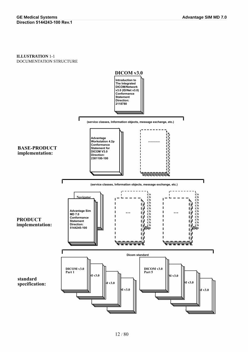
1.2Overall DICOM Conformance Statement Document Structure
The Documentation Structure of the GEMS Conformance Statements and their relationship with the DICOM v3.0 Conformance Statements is shown in ILLUSTRATION 1-1.
This document specifies the DICOM v3.0 implementation for the Advantage Sim application. It forms part of the following document set:
ADVANTAGE SIM MD
Conformance Statement
Direction # 5144243-100
DICOM Conformance Statement documents the DICOM compatibility of the Advantage Sim application, which is not already provided by the base platform application, Advantage Workstation. The DICOM compatibility of this base application is in turn described in the document:
10 / 80

GE Medical Systems Advantage SIM MD 7.0Direction 5144243-100 Rev.1
ADVANTAGE WORKSTATION 4.2Conformance Statement for DICOM V3.0Direction ........# 2381100-100
Those sections of the Advantage Sim Conformance Statement, which have been modified with respect to the Workstation Conformance Statement, are included in the current document. The reader should refer to the Advantage Workstation Conformance Statement for all sections not found in the current document.
11 / 80
GE Medical Systems Advantage SIM MD 7.0Direction 5144243-100 Rev.1
ILLUSTRATION 1-1DOCUMENTATION STRUCTURE
12 / 80
DICOM v3.0 Part 4
DICOM v3.0 Part 3
DICOM v3.0 Part 2
DICOM v3.0 Part 1
DICOM v3.0 Part 8
DICOM v3.0 Part 7
DICOM v3.0 Part 6
DICOM v3.0 Part 5
BASE-PRODUCT implementation:
standard specification:
PRODUCT implementation:
..............
DICOM v3.0 Introduction to The Integrated DICOM/Network v3.0 (ID/Net v3.0) Conformance Statement Direction: 2118780
(service classes, Information objects, message exchange, etc.)
(service classes, Information objects, message exchange, etc.)
Dicom standard
Navigator Conformance Statement for DICOM.v3.0 (ID/Net v3.0) Direction: xxxxxxx
Advantage Sim MD 7.0 Conformance Statement Direction: 5144245-100
DICOM.v3.0 Direction: xxxxxxx …
DICOM.v3.0 Direction: xxxxxxx …
Advantage Workstation 4.2p Conformance Statement for DICOM V3.0 Direction: 2381100-100
GE Medical Systems Advantage SIM MD 7.0Direction 5144243-100 Rev.1
The above DICOM Conformance Statements document the DICOM Conformance Statement and Technical Specification required to interoperate with the GEMS DICOM v3.0 network interface. Introductory information, which is applicable to all GEMS DICOM v3.0 Conformance Statements, is described in the document:
Introduction to the Integrated DICOM/Network v3.0 (ID/Net v3.0)Conformance StatementDirection ........# 2118780.
This Introduction familiarizes the reader with DICOM terminology and general concepts. It should be read prior to reading the individual products’ GEMS Conformance Statements.
The GEMS Conformance Statement, contained in this document, also specifies the Lower Layer communications, which it supports (e.g. TCP/IP). However, the Technical Specifications are defined in the DICOM v3.0 Part 8 Standard.
For more information regarding DICOM, copies of the Standard may be obtained on the Internet at <http://medical.nema.org>. Comments on the Standard may be addressed to:
DICOM Secretariat
NEMA
1300 N. 17th Street, Suite 1847
Rosslyn, VA 22209
USA
Phone: +1.703.841.3200
1.3Intended Audience
The reader of this document is concerned with software design and/or system integration issues. It is assumed that the reader of this document is familiar with the DICOM Standards and with the terminology and concepts, which are used in those Standards.
If readers are unfamiliar with DICOM terminology they should first refer to the document listed below, then read the DICOM Standard itself, prior to reading this Conformance Statement document.
Introduction to the Integrated DICOM/Network v3.0 (ID/Net v3.0)Conformance StatementDirection ........# 2118780.
1.4Scope and Field of Application
It is the intent of this document, in conjunction with the Introduction to the Integrated DICOM/Network v3.0 (ID/Net v3.0) Conformance Statement, Direction: 2118780, and the Advantage Workstation 4.2 Conformance Statement for DICOM V3.0, Direction 2381100-100 to provide an unambiguous specification for GEMS implementations. This specification, called a Conformance Statement, includes a DICOM v3.0 Conformance Statement and is necessary to ensure proper processing and interpretation of GEMS medical data exchanged using DICOM. The GEMS Conformance Statements are available to the public.
The reader of this Conformance Statement should be aware that different GEMS devices are capable of using different Information Object Definitions. For example, a GEMS CT Scanner may send images using the CT Information Object, MR Information Object, Secondary Capture Object, etc.
13 / 80
GE Medical Systems Advantage SIM MD 7.0Direction 5144243-100 Rev.1
Included in this Conformance Statement are the Module Definitions, which define all data elements, used by this GEMS implementation. If the user encounters unspecified private data elements while parsing a GEMS Data Set, the user is well advised to ignore those data elements (per the DICOM v3.0 standard). Unspecified private data element information is subject to change without notice. If, however, the device is acting as a “full fidelity storage device”, it should retain and retransmit all of the private data elements, which are sent by GEMS devices.
1.5Important Remarks
The use of these DICOM Conformance Statements, in conjunction with the DICOM v3.0 Standards, is intended to facilitate communication with GE imaging equipment. However, by itself, it is not sufficient to ensure that inter-operation will be successful. The user (or user’s agent) needs to proceed with caution and address at least four issues:
•Integration – The integration of any device into an overall system of interconnected devices goes beyond the scope of standards (DICOM v3.0), and of this introduction and associated DICOM Conformance Statements when interoperability with non-GE equipment is desired. The responsibility to analyze the applications requirements and to design a solution that integrates GE imaging and radiotherapy equipment with non–GE systems is the user’s responsibility and should not be underestimated. The user is strongly advised to ensure that such an integration analysis is correctly performed.
•Validation – Testing the complete range of possible interactions between any GE device and non–GE devices, before the connection is declared operational, should not be overlooked. Therefore, the user should ensure that any non–GE provider accepts full responsibility for all validation required for their connection with GE devices. This includes the accuracy of the image or therapy data once it has crossed the interface between the GE imaging or radiotherapy equipment and the non–GE device and the stability of the image or radiotherapy data for the intended applications.
Such a validation is required before any clinical use (diagnosis and/or treatment) is performed. It applies when images and radiotherapy data acquired on GE imaging equipment are processed/displayed on a non-GE device, as well as when images and radiotherapy data acquired on non-GE equipment is processed/displayed on a GE console or workstation.
•Future Evolution – GE understands that the DICOM Standard will evolve to meet the user’s growing requirements. GE is actively involved in the development of the DICOM v3.0 Standard. DICOM v3.0 will incorporate new features and technologies and GE may follow the evolution of the Standard. The GEMS protocol is based on DICOM v3.0 as specified in each Conformance Statement. Evolution of the Standard may require changes to devices, which have implemented DICOM v3.0. In addition, GE reserves the right to discontinue or make changes to the support of communications features (on its products) reflected on by these DICOM Conformance Statements. The user should ensure that any non–GE provider, which connects with GE devices, also plans for the future evolution of the DICOM Standard. Failures to do so will likely result in the loss of function and/or connectivity as the DICOM Standard changes and GE Products are enhanced to support these changes.
•Interaction – It is the sole responsibility of the non–GE provider to ensure that communication with the interfaced equipment does not cause degradation of GE imaging or radiotherapy equipment performance and/or function.
1.6References
A list of references which is applicable to all DICOM v3.0 Conformance Statements is included in the Introduction to the Integrated DICOM/Network v3.0 (ID/Net v3.0) Conformance Statement, Direction: 2118780.
14 / 80
GE Medical Systems Advantage SIM MD 7.0Direction 5144243-100 Rev.1
The information object implementation refers to DICOM PS3.3-1998 (Information Object Definitions).
1.7Definitions
A set of definitions which is applicable to all DICOM v3.0 Conformance Statements is included in the Introduction to the Integrated DICOM/Network v3.0 (ID/Net v3.0) Conformance Statement, Direction: 2118780.
A set of definitions, which is applicable to radiotherapy, is included in DICOM PS3.3-1998 (Information Object Definitions).
1.8Symbols and Abbreviations
A list of symbols and abbreviations which is applicable to all DICOM v3.0 Conformance Statements is included in the Introduction to the Integrated DICOM/Network v3.0 (ID/Net v3.0) Conformance Statement, Direction: 2118780.
A set of symbols and abbreviations, which is applicable to radiotherapy, is available in CEI/IEC 1217: 1996 (Radiotherapy equipment – Coordinates, movements and scales).
15 / 80
GE Medical Systems Advantage SIM MD 7.0Direction 5144243-100 Rev.1
SECTION 2NETWORK CONFORMANCE STATEMENT
2.1Introduction
This section of the conformance statement (CS) specifies the Advantage Sim compliance to DICOM Media Interchange.
Advantage Sim is a radiotherapy virtual simulation application that is installed on the same hardware platform as the base application, Advantage Workstation (Conformance Statement for DICOM V3.0 Direction: 2381100-100.). This base application is a Networked Medical Imaging Console dedicated to Examination Review and Diagnosis. The workstation uses DICOM services to import acquisition images for possible further analysis or processing, and to export images and radiotherapy data to other vendors. Additionally, radiotherapy data may be imported for further processing by Advantage Workstation or Advantage Sim.
The goal of this document is to give a detailed description of:
• the CT, MR and PET IMAGE DICOM IODs that are required to reconstruct the 3D volumes
• the SC IMAGE and RT IMAGE IOD written by the application
• the RT STRUCTURE SET and RT PLAN IOD written and red by the application.
Note that the format of this section strictly follows the format defined in DICOM Standard PS 3.2 (Conformance). Please refer to that part of the standard while reading this section.
16 / 80
GE Medical Systems Advantage SIM MD 7.0Direction 5144243-100 Rev.1
SECTION 3SECONDARY CAPTURE INFORMATION OBJECT IMPLEMENTATION
3.1Introduction
This section specifies the use of the DICOM Secondary Capture Image IOD to represent the information included in Secondary Capture images produced by this implementation. Corresponding attributes are conveyed using the module construct.
Note that the implementation described in this section relates to generation of SC Images by the Advantage Sim product only. The Advantage Sim application does not display SC Images directly, but relies on the Advantage Workstation product for this function. SC Image conformance for Advantage Workstation is described in a related document entitled Advantage Workstation 4.2 Conformance Statement for DICOM V3.0, Direction 2381100-100.
3.2SC Image IOD Implementation
This section defines the implementation of the SC Image information object in the Advantage Sim application. It refers to the DICOM Standard, Part 3 (Information Object Definition).
17 / 80
GE Medical Systems Advantage SIM MD 7.0Direction 5144243-100 Rev.1
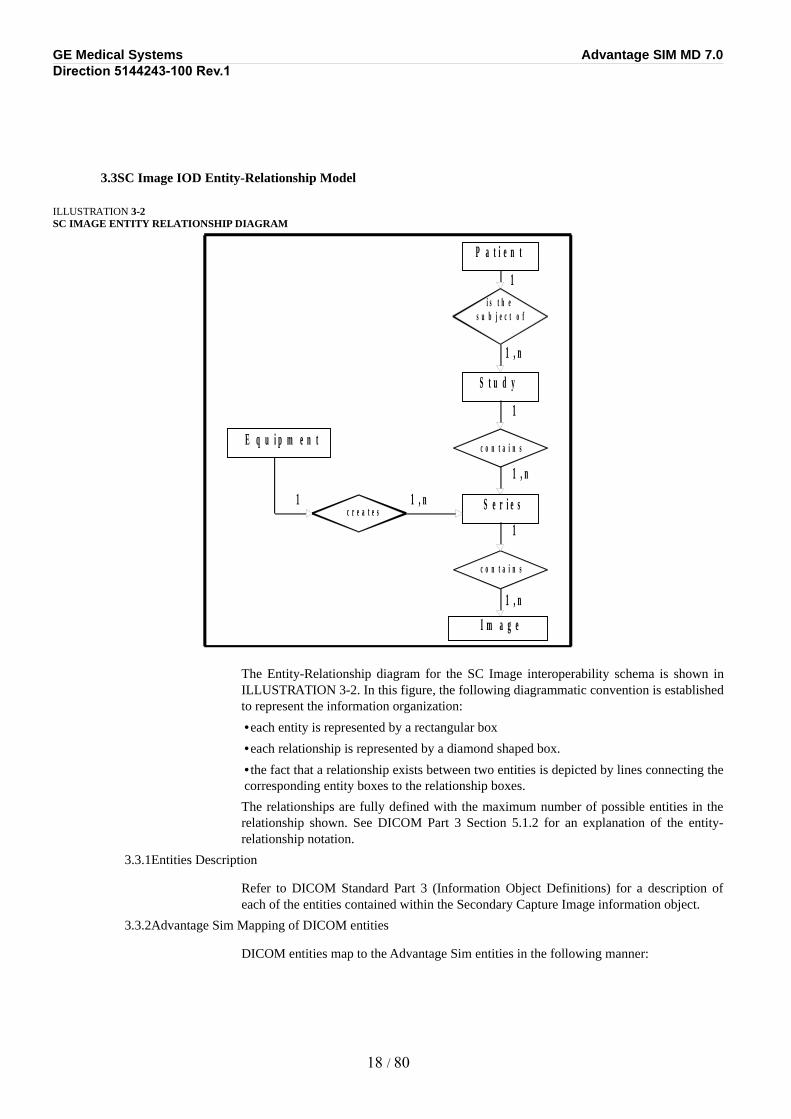
3.3SC Image IOD Entity-Relationship Model
ILLUSTRATION 3-2SC IMAGE ENTITY RELATIONSHIP DIAGRAM
The Entity-Relationship diagram for the SC Image interoperability schema is shown in ILLUSTRATION 3-2. In this figure, the following diagrammatic convention is established to represent the information organization:
•each entity is represented by a rectangular box
•each relationship is represented by a diamond shaped box.
•the fact that a relationship exists between two entities is depicted by lines connecting the corresponding entity boxes to the relationship boxes.
The relationships are fully defined with the maximum number of possible entities in the relationship shown. See DICOM Part 3 Section 5.1.2 for an explanation of the entity-relationship notation.
3.3.1Entities Description
Refer to DICOM Standard Part 3 (Information Object Definitions) for a description of each of the entities contained within the Secondary Capture Image information object.
3.3.2Advantage Sim Mapping of DICOM entities
DICOM entities map to the Advantage Sim entities in the following manner:
18 / 80
P a t i e n t
i s t h e s u b j e c t o f
S t u d y
c o n t a i n s
S e r i e s
c o n t a i n s
I m a g e
c r e a t e s
E q u i p m e n t
1
1
1
1
1 , n
1 , n
1 , n
1 , n
GE Medical Systems Advantage SIM MD 7.0Direction 5144243-100 Rev.1
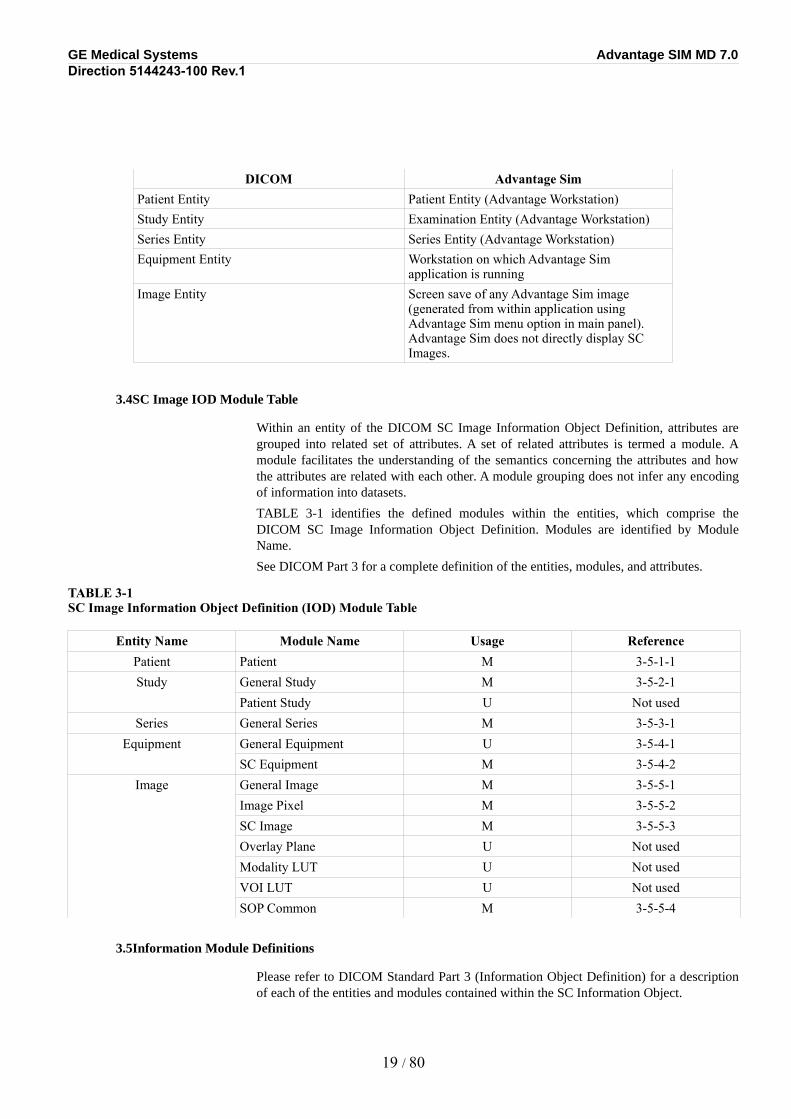
DICOM Advantage SimPatient Entity Patient Entity (Advantage Workstation)Study Entity Examination Entity (Advantage Workstation)Series Entity Series Entity (Advantage Workstation)Equipment Entity Workstation on which Advantage Sim
application is runningImage Entity Screen save of any Advantage Sim image
(generated from within application using Advantage Sim menu option in main panel). Advantage Sim does not directly display SC Images.
3.4SC Image IOD Module Table
Within an entity of the DICOM SC Image Information Object Definition, attributes are grouped into related set of attributes. A set of related attributes is termed a module. A module facilitates the understanding of the semantics concerning the attributes and how the attributes are related with each other. A module grouping does not infer any encoding of information into datasets.
TABLE 3-1 identifies the defined modules within the entities, which comprise the DICOM SC Image Information Object Definition. Modules are identified by Module Name.
See DICOM Part 3 for a complete definition of the entities, modules, and attributes.
TABLE 3-1SC Image Information Object Definition (IOD) Module Table
Entity Name Module Name Usage ReferencePatient Patient M 3-5-1-1Study General Study M 3-5-2-1
Patient Study U Not usedSeries General Series M 3-5-3-1
Equipment General Equipment U 3-5-4-1SC Equipment M 3-5-4-2
Image General Image M 3-5-5-1Image Pixel M 3-5-5-2SC Image M 3-5-5-3Overlay Plane U Not usedModality LUT U Not usedVOI LUT U Not usedSOP Common M 3-5-5-4
3.5Information Module Definitions
Please refer to DICOM Standard Part 3 (Information Object Definition) for a description of each of the entities and modules contained within the SC Information Object.
19 / 80
GE Medical Systems Advantage SIM MD 7.0Direction 5144243-100 Rev.1
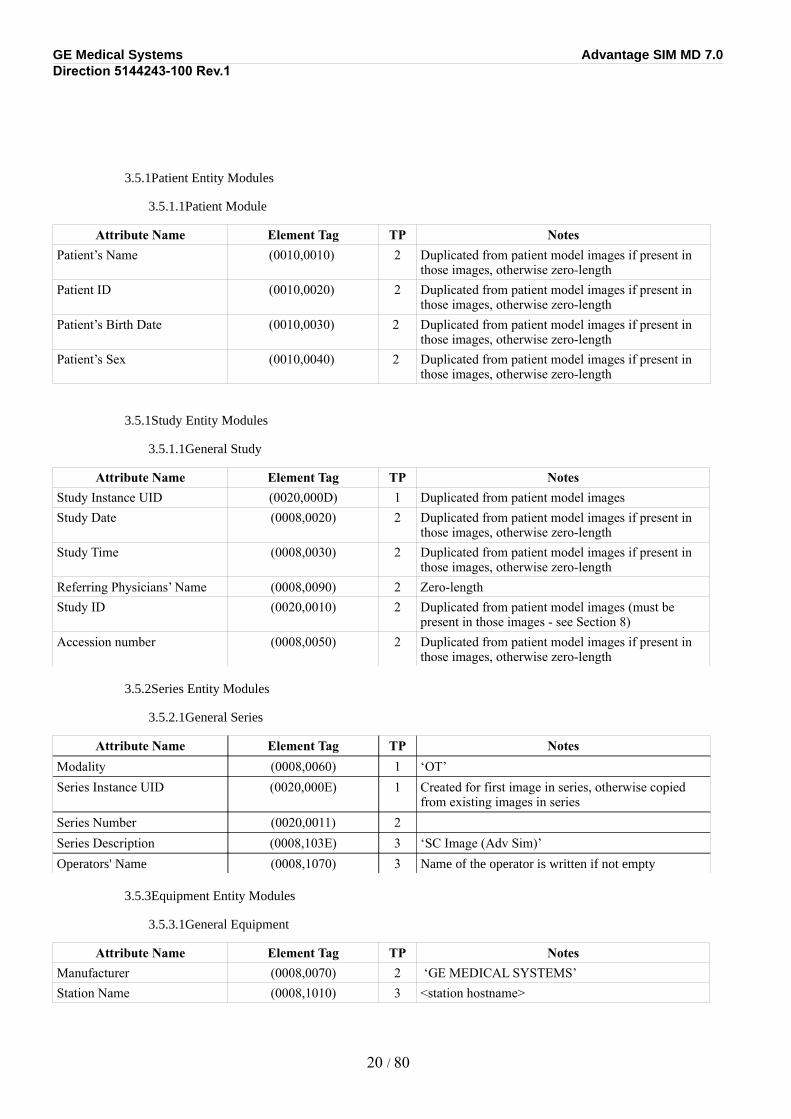
3.5.1Patient Entity Modules
3.5.1.1Patient Module
Attribute Name Element Tag TP NotesPatient’s Name (0010,0010) 2 Duplicated from patient model images if present in
those images, otherwise zero-lengthPatient ID (0010,0020) 2 Duplicated from patient model images if present in
those images, otherwise zero-lengthPatient’s Birth Date (0010,0030) 2 Duplicated from patient model images if present in
those images, otherwise zero-lengthPatient’s Sex (0010,0040) 2 Duplicated from patient model images if present in
those images, otherwise zero-length
3.5.1Study Entity Modules
3.5.1.1General Study
Attribute Name Element Tag TP NotesStudy Instance UID (0020,000D) 1 Duplicated from patient model imagesStudy Date (0008,0020) 2 Duplicated from patient model images if present in
those images, otherwise zero-lengthStudy Time (0008,0030) 2 Duplicated from patient model images if present in
those images, otherwise zero-lengthReferring Physicians’ Name (0008,0090) 2 Zero-lengthStudy ID (0020,0010) 2 Duplicated from patient model images (must be
present in those images - see Section 8)Accession number (0008,0050) 2 Duplicated from patient model images if present in
those images, otherwise zero-length
3.5.2Series Entity Modules
3.5.2.1General Series
Attribute Name Element Tag TP NotesModality (0008,0060) 1 ‘OT’Series Instance UID (0020,000E) 1 Created for first image in series, otherwise copied
from existing images in seriesSeries Number (0020,0011) 2Series Description (0008,103E) 3 ‘SC Image (Adv Sim)’Operators' Name (0008,1070) 3 Name of the operator is written if not empty
3.5.3Equipment Entity Modules
3.5.3.1General Equipment
Attribute Name Element Tag TP NotesManufacturer (0008,0070) 2 ‘GE MEDICAL SYSTEMS’Station Name (0008,1010) 3 <station hostname>
20 / 80
GE Medical Systems Advantage SIM MD 7.0Direction 5144243-100 Rev.1
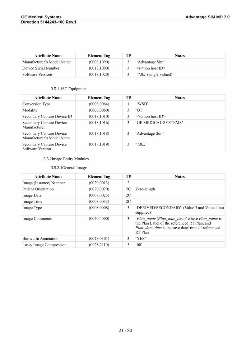
Attribute Name Element Tag TP NotesManufacturer’s Model Name (0008,1090) 3 ‘Advantage Sim’Device Serial Number (0018,1000) 3 <station host ID>Software Versions (0018,1020) 3 ‘7.0x’ (single-valued)
3.5.1.1SC Equipment
Attribute Name Element Tag TP NotesConversion Type (0008,0064) 1 ‘WSD’Modality (0008,0060) 3 ‘OT’Secondary Capture Device ID (0018,1010) 3 <station host ID>Secondary Capture Device Manufacturer
(0018,1016) 3 ‘GE MEDICAL SYSTEMS’
Secondary Capture Device Manufacturer’s Model Name
(0018,1018) 3 ‘Advantage Sim’
Secondary Capture Device Software Version
(0018,1019) 3 ‘7.0.x’
3.5.2Image Entity Modules
3.5.2.1General Image
Attribute Name Element Tag TP NotesImage (Instance) Number (0020,0013) 2Patient Orientation (0020,0020) 2C Zero-lengthImage Date (0008,0023) 2C Image Time (0008,0033) 2C Image Type (0008,0008) 3 ‘DERIVED\SECONDARY’ (Value 3 and Value 4 not
supplied)Image Comments (0020,4000) 3 ‘Plan_name (Plan_date_time)’ where Plan_name is
the Plan Label of the referenced RT Plan, and Plan_date_time is the save date/ time of referenced RT Plan
Burned In Annotation (0028,0301) 3 ‘YES’Lossy Image Compression (0028,2110) 3 ‘00’
21 / 80
GE Medical Systems Advantage SIM MD 7.0Direction 5144243-100 Rev.1
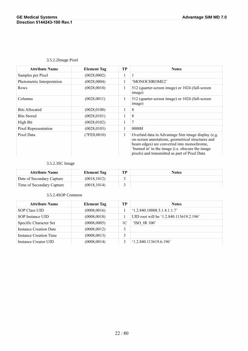
3.5.2.2Image Pixel
Attribute Name Element Tag TP NotesSamples per Pixel (0028,0002) 1 1Photometric Interpretation (0028,0004) 1 ‘MONOCHROME2’Rows (0028,0010) 1 512 (quarter-screen image) or 1024 (full-screen
image)Columns (0028,0011) 1 512 (quarter-screen image) or 1024 (full-screen
image)Bits Allocated (0028,0100) 1 8Bits Stored (0028,0101) 1 8High Bit (0028,0102) 1 7Pixel Representation (0028,0103) 1 0000HPixel Data (7FE0,0010) 1 Overlaid data in Advantage Sim image display (e.g.
on-screen annotations, geometrical structures and beam edges) are converted into monochrome, ‘burned in’ to the image (i.e. obscure the image pixels) and transmitted as part of Pixel Data
3.5.2.3SC Image
Attribute Name Element Tag TP NotesDate of Secondary Capture (0018,1012) 3Time of Secondary Capture (0018,1014) 3
3.5.2.4SOP Common
Attribute Name Element Tag TP NotesSOP Class UID (0008,0016) 1 ‘1.2.840.10008.5.1.4.1.1.7’SOP Instance UID (0008,0018) 1 UID root will be ‘1.2.840.113619.2.196’Specific Character Set (0008,0005) 1C ‘ISO_IR 100’Instance Creation Date (0008,0012) 3Instance Creation Time (0008,0013) 3Instance Creator UID (0008,0014) 3 ‘1.2.840.113619.6.196’
22 / 80
GE Medical Systems Advantage SIM MD 7.0Direction 5144243-100 Rev.1
SECTION 4RT IMAGE INFORMATION OBJECT IMPLEMENTATION
4.1Introduction
This section specifies the use of the DICOM RT Image IOD to represent the information included in images produced by this implementation. Corresponding attributes are conveyed using the module construct.
4.2RT Image IOD Implementation
This section defines the implementation of the RT Image information object in the Advantage Sim application. It refers to the DICOM Standard 2000, Part 3 (Information Object Definitions). The Advantage Sim application does not display RT Images directly, but relies on the Advantage Workstation product for this function.
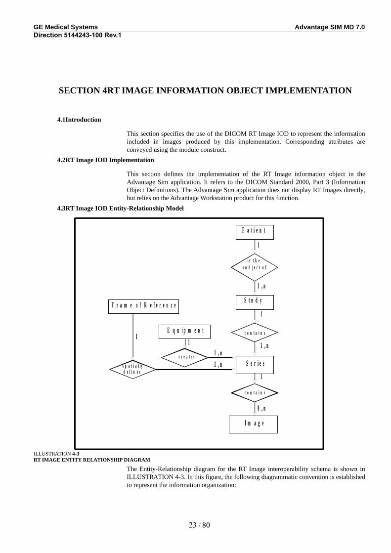
4.3RT Image IOD Entity-Relationship Model
ILLUSTRATION 4-3RT IMAGE ENTITY RELATIONSHIP DIAGRAM
The Entity-Relationship diagram for the RT Image interoperability schema is shown in ILLUSTRATION 4-3. In this figure, the following diagrammatic convention is established to represent the information organization:
23 / 80
P a t i e n t
i s t h e s u b j e c t o f
S t u d y
c o n t a i n s
S e r i e s
c o n t a i n s
I m a g e
c r e a t e s
E q u i p m e n t
1
1
1
1 , n
0 , n
1 , n
1 , n
s p a t i a l l y
1 1
d e f i n e s
F r a m e o f R e f e r e n c e
1 , n
GE Medical Systems Advantage SIM MD 7.0Direction 5144243-100 Rev.1
•each entity is represented by a rectangular box.
•each relationship is represented by a diamond shaped box.
•the fact that a relationship exists between two entities is depicted by lines connecting the corresponding entity boxes to the relationship boxes.
The relationships are fully defined with the maximum number of possible entities in the relationship shown. See DICOM Part 3 Section 5.1.2 for an explanation of the entity-relationship notation.
4.3.1Entities Description
Refer to DICOM Standard 2000 Part 3 (Information Object Definitions) for a description of each of the entities contained within the RT Image information object.
4.3.2Advantage Sim Mapping of DICOM entities
DICOM entities map to the Advantage Sim entities in the following manner:
DICOM Advantage SimPatient Entity Patient Entity (Advantage Workstation)Study Entity Examination Entity (Advantage Workstation)Series Entity Series Entity (Advantage Workstation)Frame of Reference Entity No mappingEquipment Entity Workstation on which Advantage Sim
application is runningImage Entity Screen Save of DRR (digitally-reconstructed
radiograph) image only (generated from within application using Advantage Sim menu option in main panel). Advantage Sim does not directly display RT Images.
4.4RT Image IOD Module Table
Within an entity of the DICOM RT Image Information Object Definition, attributes are grouped into related set of attributes. A set of related attributes is termed a module. A module facilitates the understanding of the semantics concerning the attributes and how the attributes are related with each other. A module grouping does not infer any encoding of information into datasets.
TABLE 4-2 identifies the defined modules within the entities, which comprise the DICOM RT Image Information Object Definition. Modules are identified by Module Name.
See DICOM Standard 2000 Part 3 for a complete definition of the entities, modules, and attributes.
TABLE 4-2RT IMAGE INFORMATION OBJECT DEFINITION (IOD) MODULE TABLE
Entity Name Module Name Usage ReferencePatient Patient M 4-5-1-1
24 / 80
GE Medical Systems Advantage SIM MD 7.0Direction 5144243-100 Rev.1
Entity Name Module Name Usage ReferenceStudy General Study M 4-5-2-1
Patient Study U Not usedSeries RT Series M 4-5-3-1
Frame of Reference Frame of Reference U Not usedEquipment General Equipment M 4-5-4-1
Image General Image M 4-5-5-1Image Pixel M 4-5-5-2Contrast/bolus C Not usedCine C Not usedMulti-Frame C Not usedRT Image M 4-5-5-3Modality LUT U Not usedVOI LUT U Not usedApproval U Not usedCurve U Not usedAudio U Not usedSOP Common M 4-5-5-4
4.5Information Module Definitions
Please refer to DICOM Standard 2000 Part 3 (Information Object Definitions) for a description of each of the entities and modules contained within the RT Image Information Object.
4.5.1Patient Entity Modules
4.5.1.1Patient Module
Attribute Name Element Tag TP NotesPatient’s Name (0010,0010) 2 Duplicated from patient model images if present in
those images, otherwise zero-lengthPatient ID (0010,0020) 2 Duplicated from patient model images if present in
those images, otherwise zero-lengthPatient’s Birth Date (0010,0030) 2 Duplicated from patient model images if present in
those images, otherwise zero-lengthPatient’s Sex (0010,0040) 2 Duplicated from patient model images if present in
those images, otherwise zero-length
4.5.2Study Entity Modules
4.5.2.1General Study
Attribute Name Element Tag TP NotesStudy Instance UID (0020,000D) 1 Duplicated from patient model images
25 / 80
GE Medical Systems Advantage SIM MD 7.0Direction 5144243-100 Rev.1
Attribute Name Element Tag TP NotesStudy Date (0008,0020) 2 Duplicated from patient model images if present in
those images, otherwise zero-lengthStudy Time (0008,0030) 2 Duplicated from patient model images if present in
those images, otherwise zero-lengthReferring Physicians’ Name (0008,0090) 2 Zero-lengthStudy ID (0020,0010) 2 Duplicated from patient model images (must be
present in those images - see Section 8)Accession number (0008,0050) 2 Duplicated from patient model images if present in
those images, otherwise zero-length
4.5.1Series Entity Modules
4.5.1.1RT Series
Attribute Name Element Tag TP NotesModality (0008,0060) 1 ‘RTIMAGE’Series Instance UID (0020,000E) 1 Created for first image in series, otherwise copied
from existing images in seriesSeries Number (0020,0011) 2Series Description (0008,103E) 3 ‘Adv Sim RT Images’
4.5.1Equipment Entity Modules
4.5.1.1General Equipment
Attribute Name Element Tag TP NotesManufacturer (0008,0070) 2 ‘GE MEDICAL SYSTEMS’Station Name (0008,1010) 3 <station hostname> Manufacturer’s Model Name (0008,1090) 3 ‘Advantage Sim’Device Serial Number (0018,1000) 3 <station host ID>Software Versions (0018,1020) 3 ‘7.0.x’ (single-valued)
4.5.2Image Entity Modules
4.5.2.1General Image
Attribute Name Element Tag TP NotesImage (Instance) Number (0020,0013) 2Patient Orientation (0020,0020) 2C Zero-lengthImage Date (0008,0023) 2C Image Time (0008,0033) 2C Image Comments (0020,4000) 3 ‘Plan_name (Plan_date_time)’ where Plan_name is
the Plan Label of the referenced RT Plan, and Plan_date_time is the save date/ time of referenced RT Plan
26 / 80
GE Medical Systems Advantage SIM MD 7.0Direction 5144243-100 Rev.1
4.5.2.2Image Pixel
Attribute Name Element Tag TP NotesSamples per Pixel (0028,0002) 1 1Photometric Interpretation (0028,0004) 1 ‘MONOCHROME2’Rows (0028,0010) 1 512 (quarter-screen image) or ‘1024’ (full-screen
image)Columns (0028,0011) 1 512 (quarter-screen image) or ‘1024’ (full-screen
image)Bits Allocated (0028,0100) 1 8Bits Stored (0028,0101) 1 8High Bit (0028,0102) 1 7Pixel Representation (0028,0103) 1 0000HPixel Data (7FE0,0010) 1 Overlaid data in Advantage Sim image display (e.g.
on-screen annotations, geometrical structures and beam edges) are converted into monochrome, ‘burned in’ to the image (i.e. obscure the image pixels) and transmitted as part of Pixel Data
4.5.1.1RT Image
Attribute Name Element Tag TP NotesRT Image Label (3002,0002) 1 Name of associated beam in referenced RT PlanRT Image Name (3002,0003) 3 ‘Plan_name (Plan_date_time)’ where Plan_name is
the Plan Label of the referenced RT Plan, and Plan_date_time is the save date/time of referenced RT Plan
Operators’ Name (0008,1070) 2 Is written if not zero length
Image Type (0008,0008) 1 ‘DERIVED\SECONDARY\DRR’ Conversion Type (0008,0064) 2 ‘WSD’Reported Values Origin (3002,000A) 2C ‘PLAN’RT Image Plane (3002,000C) 1 ‘NORMAL’X-Ray Image Receptor Angle (3002,000E) 2 0Image Plane Pixel Spacing (3002,0011) 2 Pixels will always be squareRT Image Position (3002,0012) 2 First pixel transmitted always has negative x and
positive y values (i.e. image viewed from treatment machine gantry with eyes fixed along gantry X axis and top of head towards gantry wall)
Radiation Machine Name (3002,0020) 2 Name (including suffix) of machine associated with beam in Advantage Sim
Primary Dosimeter Unit (300A,00B3) 2 Zero-lengthRadiation Machine SAD (3002,0022) 2 Source-axis distance of machine associated with
beam in Advantage SimRT Image SID (3002,0026) 2 Equal to SAD of machine associated with beam in
Advantage Sim (i.e. image is always projected onto isocenter)
27 / 80
GE Medical Systems Advantage SIM MD 7.0Direction 5144243-100 Rev.1
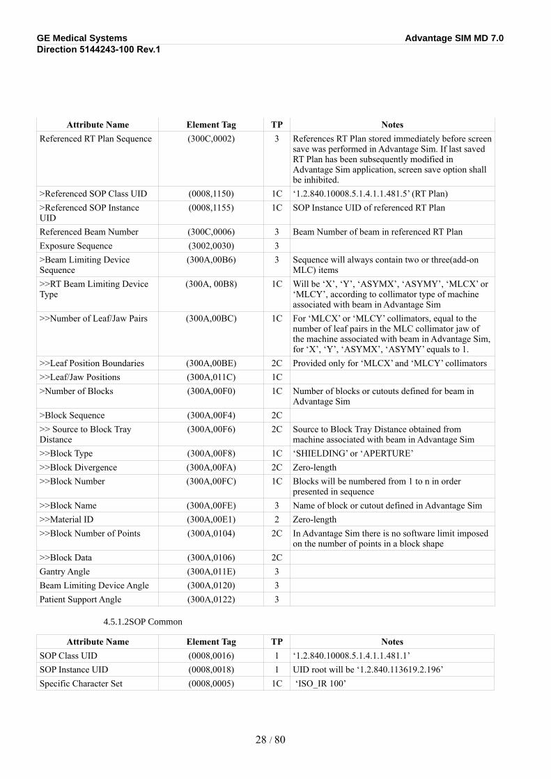
Attribute Name Element Tag TP NotesReferenced RT Plan Sequence (300C,0002) 3 References RT Plan stored immediately before screen
save was performed in Advantage Sim. If last saved RT Plan has been subsequently modified in Advantage Sim application, screen save option shall be inhibited.
>Referenced SOP Class UID (0008,1150) 1C ‘1.2.840.10008.5.1.4.1.1.481.5’ (RT Plan)>Referenced SOP Instance UID
(0008,1155) 1C SOP Instance UID of referenced RT Plan
Referenced Beam Number (300C,0006) 3 Beam Number of beam in referenced RT PlanExposure Sequence (3002,0030) 3>Beam Limiting Device Sequence
(300A,00B6) 3 Sequence will always contain two or three(add-on MLC) items
>>RT Beam Limiting Device Type
(300A, 00B8) 1C Will be ‘X’, ‘Y’, ‘ASYMX’, ‘ASYMY’, ‘MLCX’ or ‘MLCY’, according to collimator type of machine associated with beam in Advantage Sim
>>Number of Leaf/Jaw Pairs (300A,00BC) 1C For ‘MLCX’ or ‘MLCY’ collimators, equal to the number of leaf pairs in the MLC collimator jaw of the machine associated with beam in Advantage Sim, for ‘X’, ‘Y’, ‘ASYMX’, ‘ASYMY’ equals to 1.
>>Leaf Position Boundaries (300A,00BE) 2C Provided only for ‘MLCX’ and ‘MLCY’ collimators>>Leaf/Jaw Positions (300A,011C) 1C>Number of Blocks (300A,00F0) 1C Number of blocks or cutouts defined for beam in
Advantage Sim>Block Sequence (300A,00F4) 2C>> Source to Block Tray Distance
(300A,00F6) 2C Source to Block Tray Distance obtained from machine associated with beam in Advantage Sim
>>Block Type (300A,00F8) 1C ‘SHIELDING’ or ‘APERTURE’>>Block Divergence (300A,00FA) 2C Zero-length>>Block Number (300A,00FC) 1C Blocks will be numbered from 1 to n in order
presented in sequence>>Block Name (300A,00FE) 3 Name of block or cutout defined in Advantage Sim>>Material ID (300A,00E1) 2 Zero-length>>Block Number of Points (300A,0104) 2C In Advantage Sim there is no software limit imposed
on the number of points in a block shape>>Block Data (300A,0106) 2CGantry Angle (300A,011E) 3Beam Limiting Device Angle (300A,0120) 3Patient Support Angle (300A,0122) 3
4.5.1.2SOP Common
Attribute Name Element Tag TP NotesSOP Class UID (0008,0016) 1 ‘1.2.840.10008.5.1.4.1.1.481.1’SOP Instance UID (0008,0018) 1 UID root will be ‘1.2.840.113619.2.196’Specific Character Set (0008,0005) 1C ‘ISO_IR 100’
28 / 80

GE Medical Systems Advantage SIM MD 7.0Direction 5144243-100 Rev.1
Attribute Name Element Tag TP NotesInstance Creation Date (0008,0012) 3Instance Creation Time (0008,0013) 3Instance Creator UID (0008,0014) 3 ‘1.2.840.113619.6.196’
29 / 80
GE Medical Systems Advantage SIM MD 7.0Direction 5144243-100 Rev.1
SECTION 5RT STRUCTURE SET INFORMATION OBJECT IMPLEMENTATION (AS SCU) AND REQUIREMENTS (AS SCP)
5.1Introduction
This section specifies the use of the DICOM RT Structure Set IOD to represent the information included in structure sets produced by this implementation, and also specifies the requirements for the RT Structure Set IOD when being used as input to Advantage Sim. Corresponding attributes are conveyed using the module construct.
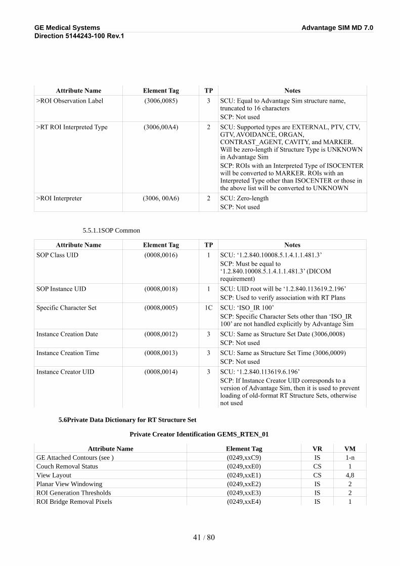
Advantage Sim implements the RT Structure Set IOD as a Standard Extended object, containing six additional elements defined in the Structure Set Module (see Section 5-5-5-1 of this document). These attributes are:
•In the Structure Set Module, top level:
•Couch Removal Status (0249,xxE0), indicating if the treatment couch had been removed by the Advantage Sim software;
•View Layout (0249,xxE1), storing the arrangement of views;
• Planar View Windowing (0249,xxE2), the display parameters for the 2D non-DRR views.
•·Remove Couch plane's coordinates (0249,xxE6), if the treatment couch had been removed by the Advantage Sim software (See (0249,xxE0)), this value stores the coordinate used for treatment couch removal on Axial view.
•In the Structure Set Module, Structure Set ROI Sequence:
•ROI Generation Thresholds (0249,xxE3)
•ROI Bridge Removal Pixels (0249,xxE4), storing the generation parameters for automatically generated structures.
•In the Referenced Frame of Reference Sequence:
•3D Model name (0249,xxE5), storing the unique 3D model name assigned for each series.
These attributes are provided for enhanced functionality when reading RT Structure Sets created by the Advantage Sim application itself. They should be ignored by SCP implementations interpreting these objects. These attributes are not required in RT Structure Sets created by SCU implementations for use in Advantage Sim.
Note: This implementation of the RT Structure Set IOD contains the attribute Instance Number (0020,0013), formerly known as Image Number, added to the RT Structure Set object definition in September 1999 (Change Proposals CP-134 and CP-99).
Note: In comparison to previous releases of Advantage Sim, this implementation of the RT Structure Set IOD does NOT contain the Contour Number ((3006,0048), VR=IS, VM=1) and Attached Contours ((3006,0049), VR=IS, VM=1-n), added to the RT Structure Set object definition in September 1999 (Change Proposal CP-133).
5.2RT Structure Set IOD Implementation
This section defines the implementation of the RT Structure Set information object in the Advantage Sim application. It refers to the DICOM Standard 2000 Part 3 (Information Object Definitions).
30 / 80
GE Medical Systems Advantage SIM MD 7.0Direction 5144243-100 Rev.1
In the following tables, notes are provided for when Advantage Sim is acting as a producer of objects (SCU), and a consumer of objects (SCP). Notes in UPPER CASE LETTERS represent restrictions on object contents imposed by Advantage Sim when acting as an SCP (object consumer).
5.3RT Structure Set IOD Entity-Relationship Model
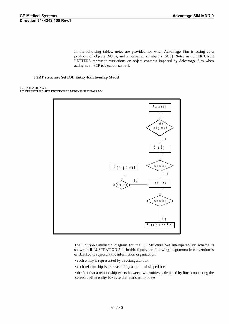
ILLUSTRATION 5-4RT STRUCTURE SET ENTITY RELATIONSHIP DIAGRAM
The Entity-Relationship diagram for the RT Structure Set interoperability schema is shown in ILLUSTRATION 5-4. In this figure, the following diagrammatic convention is established to represent the information organization:
•each entity is represented by a rectangular box.
•each relationship is represented by a diamond shaped box.
•the fact that a relationship exists between two entities is depicted by lines connecting the corresponding entity boxes to the relationship boxes.
31 / 80
P a t i e n t
i s t h e s u b j e c t o f
S t u d y
c o n t a i n s
S e r i e s
c o n t a i n s
c r e a t e s
E q u i p m e n t
1
1
1
1
1 , n
1 , n
1 , n
S t r u c t u r e S e t 0 , n
GE Medical Systems Advantage SIM MD 7.0Direction 5144243-100 Rev.1
The relationships are fully defined with the maximum number of possible entities in the relationship shown. See DICOM Part 3 Section 5.1.2 for an explanation of the entity-relationship notation.
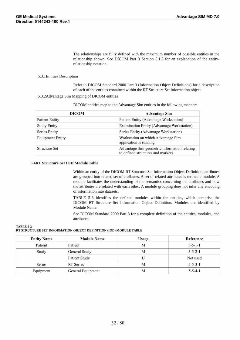
5.3.1Entities Description
Refer to DICOM Standard 2000 Part 3 (Information Object Definitions) for a description of each of the entities contained within the RT Structure Set information object.
5.3.2Advantage Sim Mapping of DICOM entities
DICOM entities map to the Advantage Sim entities in the following manner:
DICOM Advantage SimPatient Entity Patient Entity (Advantage Workstation)Study Entity Examination Entity (Advantage Workstation)Series Entity Series Entity (Advantage Workstation)Equipment Entity Workstation on which Advantage Sim
application is runningStructure Set Advantage Sim geometric information relating
to defined structures and markers
5.4RT Structure Set IOD Module Table
Within an entity of the DICOM RT Structure Set Information Object Definition, attributes are grouped into related set of attributes. A set of related attributes is termed a module. A module facilitates the understanding of the semantics concerning the attributes and how the attributes are related with each other. A module grouping does not infer any encoding of information into datasets.
TABLE 5-3 identifies the defined modules within the entities, which comprise the DICOM RT Structure Set Information Object Definition. Modules are identified by Module Name.
See DICOM Standard 2000 Part 3 for a complete definition of the entities, modules, and attributes.
TABLE 5-3RT STRUCTURE SET INFORMATION OBJECT DEFINITION (IOD) MODULE TABLE
Entity Name Module Name Usage ReferencePatient Patient M 5-5-1-1Study General Study M 5-5-2-1
Patient Study U Not usedSeries RT Series M 5-5-3-1
Equipment General Equipment M 5-5-4-1
32 / 80
GE Medical Systems Advantage SIM MD 7.0Direction 5144243-100 Rev.1
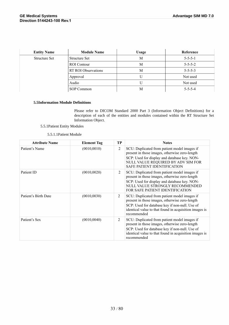
Entity Name Module Name Usage ReferenceStructure Set Structure Set M 5-5-5-1
ROI Contour M 5-5-5-2RT ROI Observations M 5-5-5-3Approval U Not usedAudio U Not usedSOP Common M 5-5-5-4
5.5Information Module Definitions
Please refer to DICOM Standard 2000 Part 3 (Information Object Definitions) for a description of each of the entities and modules contained within the RT Structure Set Information Object.
5.5.1Patient Entity Modules
5.5.1.1Patient Module
Attribute Name Element Tag TP NotesPatient’s Name (0010,0010) 2 SCU: Duplicated from patient model images if
present in those images, otherwise zero-lengthSCP: Used for display and database key. NON-NULL VALUE REQUIRED BY ADV SIM FOR SAFE PATIENT IDENTIFICATION
Patient ID (0010,0020) 2 SCU: Duplicated from patient model images if present in those images, otherwise zero-lengthSCP: Used for display and database key. NON-NULL VALUE STRONGLY RECOMMENDED FOR SAFE PATIENT IDENTIFICATION
Patient’s Birth Date (0010,0030) 2 SCU: Duplicated from patient model images if present in those images, otherwise zero-lengthSCP: Used for database key if non-null. Use of identical value to that found in acquisition images is recommended
Patient’s Sex (0010,0040) 2 SCU: Duplicated from patient model images if present in those images, otherwise zero-lengthSCP: Used for database key if non-null. Use of identical value to that found in acquisition images is recommended
33 / 80

GE Medical Systems Advantage SIM MD 7.0Direction 5144243-100 Rev.1
5.5.2Study Entity Modules
5.5.2.1General Study
Attribute Name Element Tag TP NotesStudy Instance UID (0020,000D) 1 SCU: Duplicated from patient model images
SCP: Not usedStudy Date (0008,0020) 2 SCU: Duplicated from patient model images if
present in those images, otherwise zero-lengthSCP: Not used
Study Time (0008,0030) 2 SCU: Duplicated from patient model images if present in those images, otherwise zero-lengthSCP: Not used
Referring Physicians’ Name (0008,0090) 2 SCU: Zero-lengthSCP: Not used
Study ID (0020,0010) 2 SCU: Duplicated from patient model images (must be present in those images – see )SCP: Not used
Accession number (0008,0050) 2 SCU: Duplicated from patient model images if present in those images, otherwise zero-lengthSCP: Not used
5.5.3Series Entity Modules
5.5.3.1RT Series
Attribute Name Element Tag TP NotesModality (0008,0060) 1 SCU: ‘RTSTRUCT’
SCP: Must be ‘RTSTRUCT’ (DICOM requirement)Series Instance UID (0020,000E) 1 SCU: Created for first image in series, otherwise
copied from existing images in seriesSCP: Not used
Series Number (0020,0011) 2 SCU: always providedSCP: Used for display if non-null
Series Description (0008,103E) 3 SCU: ‘Adv Sim RT Structure Sets’SCP: Used for display if provided
34 / 80
GE Medical Systems Advantage SIM MD 7.0Direction 5144243-100 Rev.1
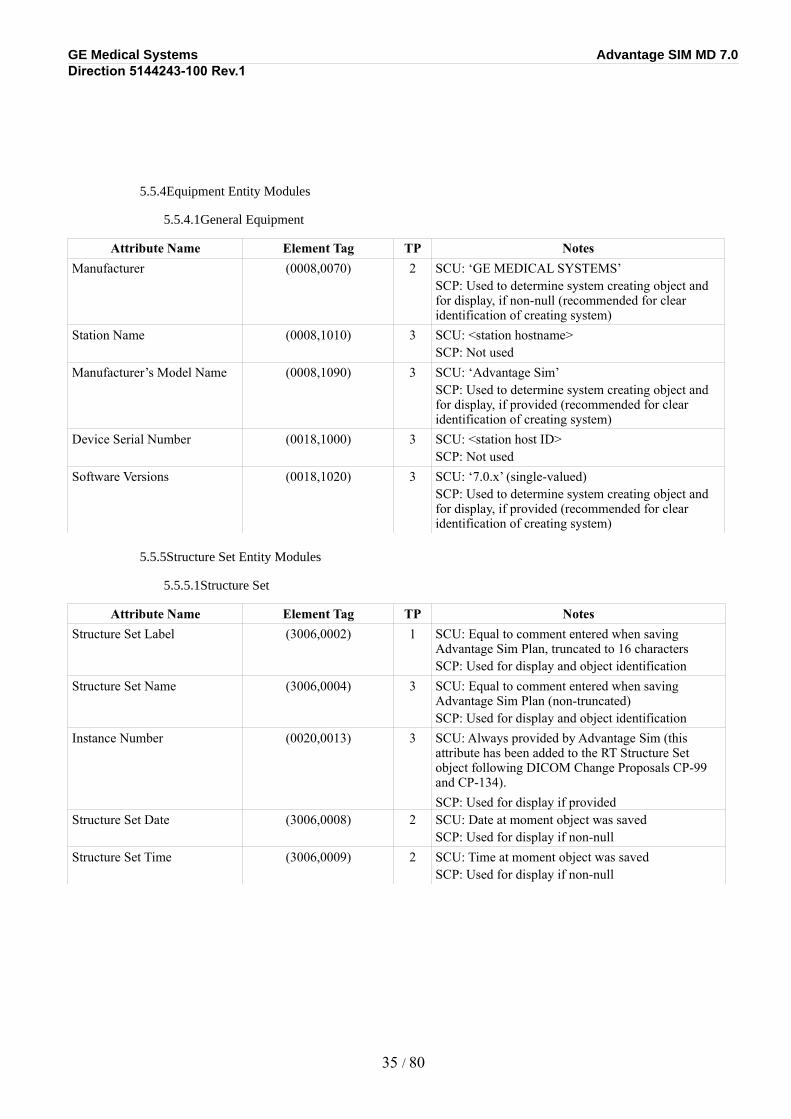
5.5.4Equipment Entity Modules
5.5.4.1General Equipment
Attribute Name Element Tag TP NotesManufacturer (0008,0070) 2 SCU: ‘GE MEDICAL SYSTEMS’
SCP: Used to determine system creating object and for display, if non-null (recommended for clear identification of creating system)
Station Name (0008,1010) 3 SCU: <station hostname>SCP: Not used
Manufacturer’s Model Name (0008,1090) 3 SCU: ‘Advantage Sim’SCP: Used to determine system creating object and for display, if provided (recommended for clear identification of creating system)
Device Serial Number (0018,1000) 3 SCU: <station host ID>SCP: Not used
Software Versions (0018,1020) 3 SCU: ‘7.0.x’ (single-valued)SCP: Used to determine system creating object and for display, if provided (recommended for clear identification of creating system)
5.5.5Structure Set Entity Modules
5.5.5.1Structure Set
Attribute Name Element Tag TP NotesStructure Set Label (3006,0002) 1 SCU: Equal to comment entered when saving
Advantage Sim Plan, truncated to 16 charactersSCP: Used for display and object identification
Structure Set Name (3006,0004) 3 SCU: Equal to comment entered when saving Advantage Sim Plan (non-truncated)SCP: Used for display and object identification
Instance Number (0020,0013) 3 SCU: Always provided by Advantage Sim (this attribute has been added to the RT Structure Set object following DICOM Change Proposals CP-99 and CP-134).SCP: Used for display if provided
Structure Set Date (3006,0008) 2 SCU: Date at moment object was savedSCP: Used for display if non-null
Structure Set Time (3006,0009) 2 SCU: Time at moment object was savedSCP: Used for display if non-null
35 / 80
GE Medical Systems Advantage SIM MD 7.0Direction 5144243-100 Rev.1
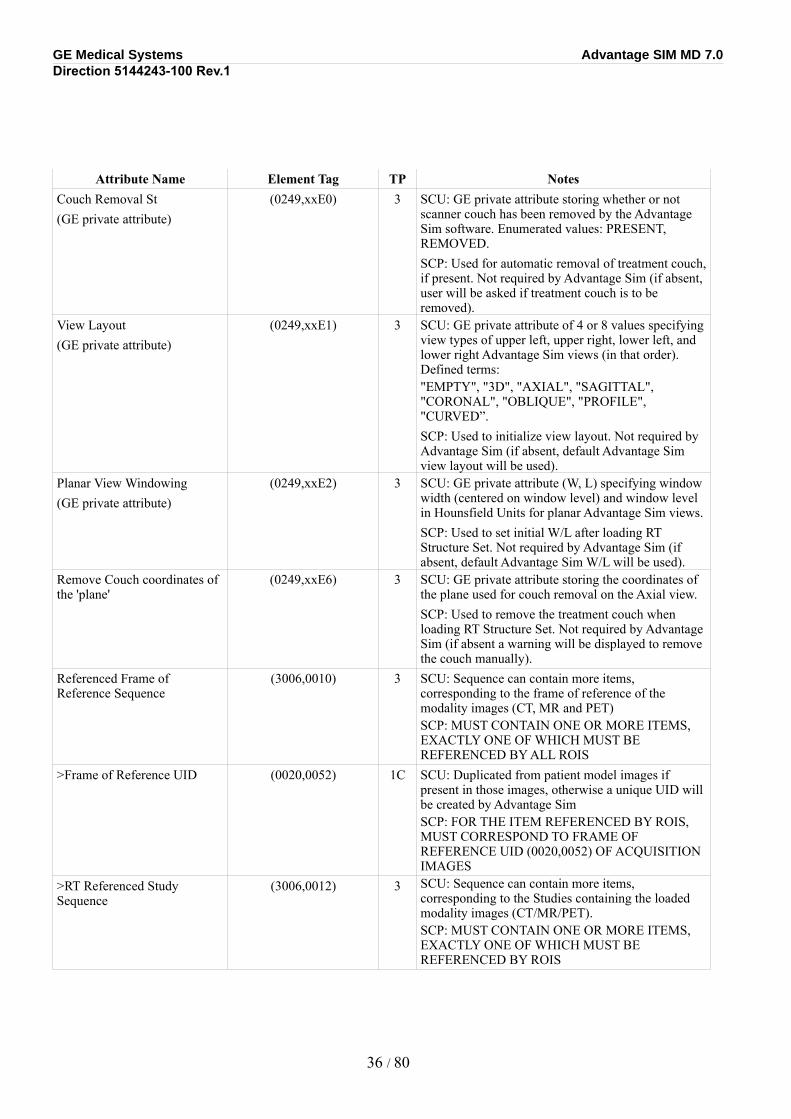
Attribute Name Element Tag TP NotesCouch Removal St(GE private attribute)
(0249,xxE0) 3 SCU: GE private attribute storing whether or not scanner couch has been removed by the Advantage Sim software. Enumerated values: PRESENT, REMOVED.SCP: Used for automatic removal of treatment couch, if present. Not required by Advantage Sim (if absent, user will be asked if treatment couch is to be removed).
View Layout(GE private attribute)
(0249,xxE1) 3 SCU: GE private attribute of 4 or 8 values specifying view types of upper left, upper right, lower left, and lower right Advantage Sim views (in that order). Defined terms:"EMPTY", "3D", "AXIAL", "SAGITTAL", "CORONAL", "OBLIQUE", "PROFILE", "CURVED”.SCP: Used to initialize view layout. Not required by Advantage Sim (if absent, default Advantage Sim view layout will be used).
Planar View Windowing(GE private attribute)
(0249,xxE2) 3 SCU: GE private attribute (W, L) specifying window width (centered on window level) and window level in Hounsfield Units for planar Advantage Sim views.SCP: Used to set initial W/L after loading RT Structure Set. Not required by Advantage Sim (if absent, default Advantage Sim W/L will be used).
Remove Couch coordinates of the 'plane'
(0249,xxE6) 3 SCU: GE private attribute storing the coordinates of the plane used for couch removal on the Axial view.SCP: Used to remove the treatment couch when loading RT Structure Set. Not required by Advantage Sim (if absent a warning will be displayed to remove the couch manually).
Referenced Frame of Reference Sequence
(3006,0010) 3 SCU: Sequence can contain more items, corresponding to the frame of reference of the modality images (CT, MR and PET)SCP: MUST CONTAIN ONE OR MORE ITEMS, EXACTLY ONE OF WHICH MUST BE REFERENCED BY ALL ROIS
>Frame of Reference UID (0020,0052) 1C SCU: Duplicated from patient model images if present in those images, otherwise a unique UID will be created by Advantage SimSCP: FOR THE ITEM REFERENCED BY ROIS, MUST CORRESPOND TO FRAME OF REFERENCE UID (0020,0052) OF ACQUISITION IMAGES
>RT Referenced Study Sequence
(3006,0012) 3 SCU: Sequence can contain more items, corresponding to the Studies containing the loaded modality images (CT/MR/PET).SCP: MUST CONTAIN ONE OR MORE ITEMS, EXACTLY ONE OF WHICH MUST BE REFERENCED BY ROIS
36 / 80
GE Medical Systems Advantage SIM MD 7.0Direction 5144243-100 Rev.1
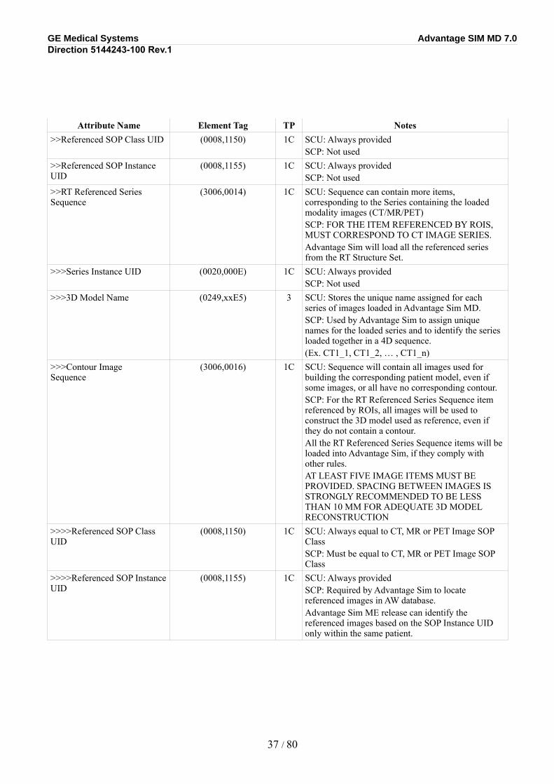
Attribute Name Element Tag TP Notes>>Referenced SOP Class UID (0008,1150) 1C SCU: Always provided
SCP: Not used>>Referenced SOP Instance UID
(0008,1155) 1C SCU: Always providedSCP: Not used
>>RT Referenced Series Sequence
(3006,0014) 1C SCU: Sequence can contain more items, corresponding to the Series containing the loaded modality images (CT/MR/PET)SCP: FOR THE ITEM REFERENCED BY ROIS, MUST CORRESPOND TO CT IMAGE SERIES.Advantage Sim will load all the referenced series from the RT Structure Set.
>>>Series Instance UID (0020,000E) 1C SCU: Always providedSCP: Not used
>>>3D Model Name (0249,xxE5) 3 SCU: Stores the unique name assigned for each series of images loaded in Advantage Sim MD. SCP: Used by Advantage Sim to assign unique names for the loaded series and to identify the series loaded together in a 4D sequence. (Ex. CT1_1, CT1_2, … , CT1_n)
>>>Contour Image Sequence
(3006,0016) 1C SCU: Sequence will contain all images used for building the corresponding patient model, even if some images, or all have no corresponding contour.SCP: For the RT Referenced Series Sequence item referenced by ROIs, all images will be used to construct the 3D model used as reference, even if they do not contain a contour. All the RT Referenced Series Sequence items will be loaded into Advantage Sim, if they comply with other rules.AT LEAST FIVE IMAGE ITEMS MUST BE PROVIDED. SPACING BETWEEN IMAGES IS STRONGLY RECOMMENDED TO BE LESS THAN 10 MM FOR ADEQUATE 3D MODEL RECONSTRUCTION
>>>>Referenced SOP Class UID
(0008,1150) 1C SCU: Always equal to CT, MR or PET Image SOP ClassSCP: Must be equal to CT, MR or PET Image SOP Class
>>>>Referenced SOP Instance UID
(0008,1155) 1C SCU: Always providedSCP: Required by Advantage Sim to locate referenced images in AW database. Advantage Sim ME release can identify the referenced images based on the SOP Instance UID only within the same patient.
37 / 80
GE Medical Systems Advantage SIM MD 7.0Direction 5144243-100 Rev.1
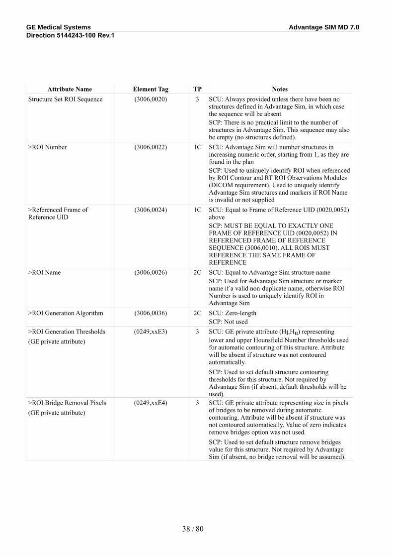
Attribute Name Element Tag TP NotesStructure Set ROI Sequence (3006,0020) 3 SCU: Always provided unless there have been no
structures defined in Advantage Sim, in which case the sequence will be absentSCP: There is no practical limit to the number of structures in Advantage Sim. This sequence may also be empty (no structures defined).
>ROI Number (3006,0022) 1C SCU: Advantage Sim will number structures in increasing numeric order, starting from 1, as they are found in the planSCP: Used to uniquely identify ROI when referenced by ROI Contour and RT ROI Observations Modules (DICOM requirement). Used to uniquely identify Advantage Sim structures and markers if ROI Name is invalid or not supplied
>Referenced Frame of Reference UID
(3006,0024) 1C SCU: Equal to Frame of Reference UID (0020,0052) aboveSCP: MUST BE EQUAL TO EXACTLY ONE FRAME OF REFERENCE UID (0020,0052) IN REFERENCED FRAME OF REFERENCE SEQUENCE (3006,0010). ALL ROIS MUST REFERENCE THE SAME FRAME OF REFERENCE
>ROI Name (3006,0026) 2C SCU: Equal to Advantage Sim structure nameSCP: Used for Advantage Sim structure or marker name if a valid non-duplicate name, otherwise ROI Number is used to uniquely identify ROI in Advantage Sim
>ROI Generation Algorithm (3006,0036) 2C SCU: Zero-lengthSCP: Not used
>ROI Generation Thresholds(GE private attribute)
(0249,xxE3) 3 SCU: GE private attribute (Hl,Hu) representing lower and upper Hounsfield Number thresholds used for automatic contouring of this structure. Attribute will be absent if structure was not contoured automatically.SCP: Used to set default structure contouring thresholds for this structure. Not required by Advantage Sim (if absent, default thresholds will be used).
>ROI Bridge Removal Pixels(GE private attribute)
(0249,xxE4) 3 SCU: GE private attribute representing size in pixels of bridges to be removed during automatic contouring. Attribute will be absent if structure was not contoured automatically. Value of zero indicates remove bridges option was not used.SCP: Used to set default structure remove bridges value for this structure. Not required by Advantage Sim (if absent, no bridge removal will be assumed).
38 / 80
GE Medical Systems Advantage SIM MD 7.0Direction 5144243-100 Rev.1
5.5.1.1ROI Contour
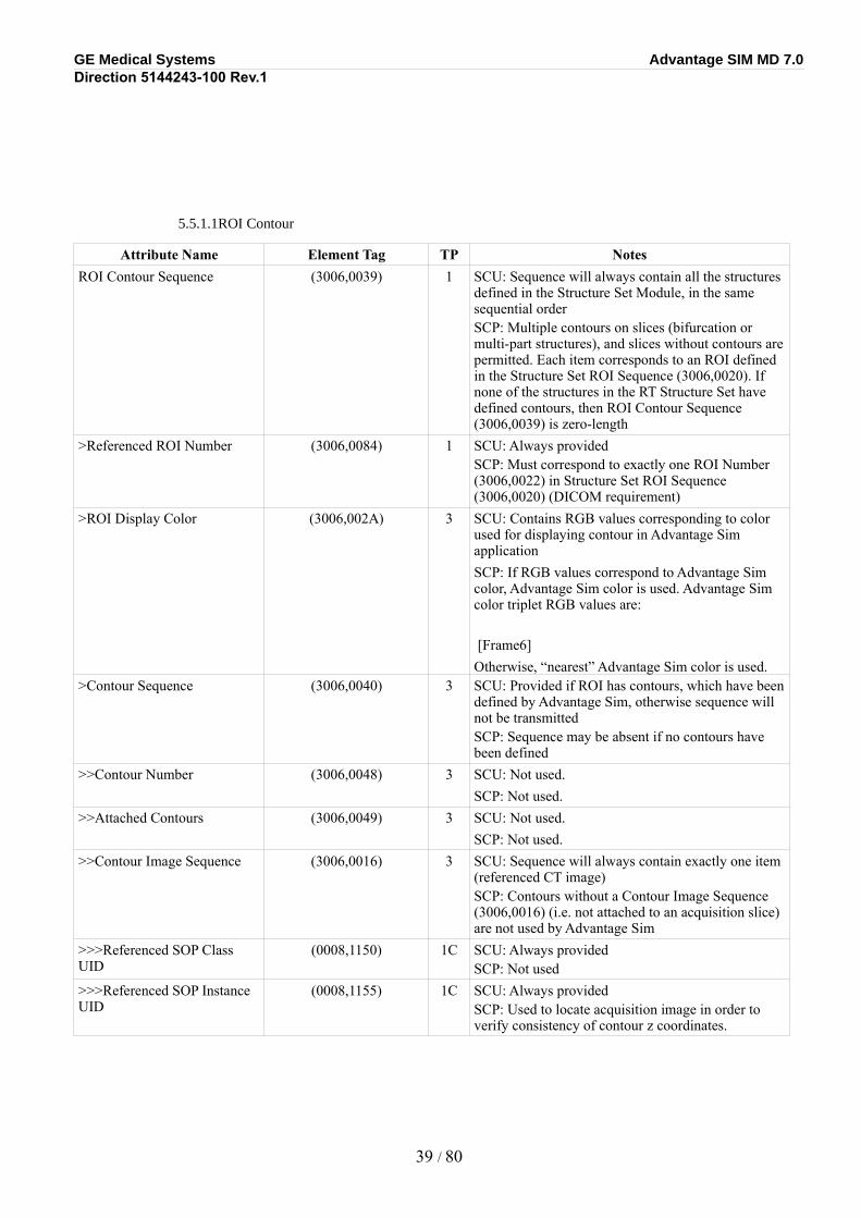
Attribute Name Element Tag TP NotesROI Contour Sequence (3006,0039) 1 SCU: Sequence will always contain all the structures
defined in the Structure Set Module, in the same sequential orderSCP: Multiple contours on slices (bifurcation or multi-part structures), and slices without contours are permitted. Each item corresponds to an ROI defined in the Structure Set ROI Sequence (3006,0020). If none of the structures in the RT Structure Set have defined contours, then ROI Contour Sequence (3006,0039) is zero-length
>Referenced ROI Number (3006,0084) 1 SCU: Always providedSCP: Must correspond to exactly one ROI Number (3006,0022) in Structure Set ROI Sequence (3006,0020) (DICOM requirement)
>ROI Display Color (3006,002A) 3 SCU: Contains RGB values corresponding to color used for displaying contour in Advantage Sim applicationSCP: If RGB values correspond to Advantage Sim color, Advantage Sim color is used. Advantage Sim color triplet RGB values are:
[Frame6] Otherwise, “nearest” Advantage Sim color is used.
>Contour Sequence (3006,0040) 3 SCU: Provided if ROI has contours, which have been defined by Advantage Sim, otherwise sequence will not be transmittedSCP: Sequence may be absent if no contours have been defined
>>Contour Number (3006,0048) 3 SCU: Not used.SCP: Not used.
>>Attached Contours (3006,0049) 3 SCU: Not used.SCP: Not used.
>>Contour Image Sequence (3006,0016) 3 SCU: Sequence will always contain exactly one item (referenced CT image)SCP: Contours without a Contour Image Sequence (3006,0016) (i.e. not attached to an acquisition slice) are not used by Advantage Sim
>>>Referenced SOP Class UID
(0008,1150) 1C SCU: Always providedSCP: Not used
>>>Referenced SOP Instance UID
(0008,1155) 1C SCU: Always providedSCP: Used to locate acquisition image in order to verify consistency of contour z coordinates.
39 / 80
GE Medical Systems Advantage SIM MD 7.0Direction 5144243-100 Rev.1
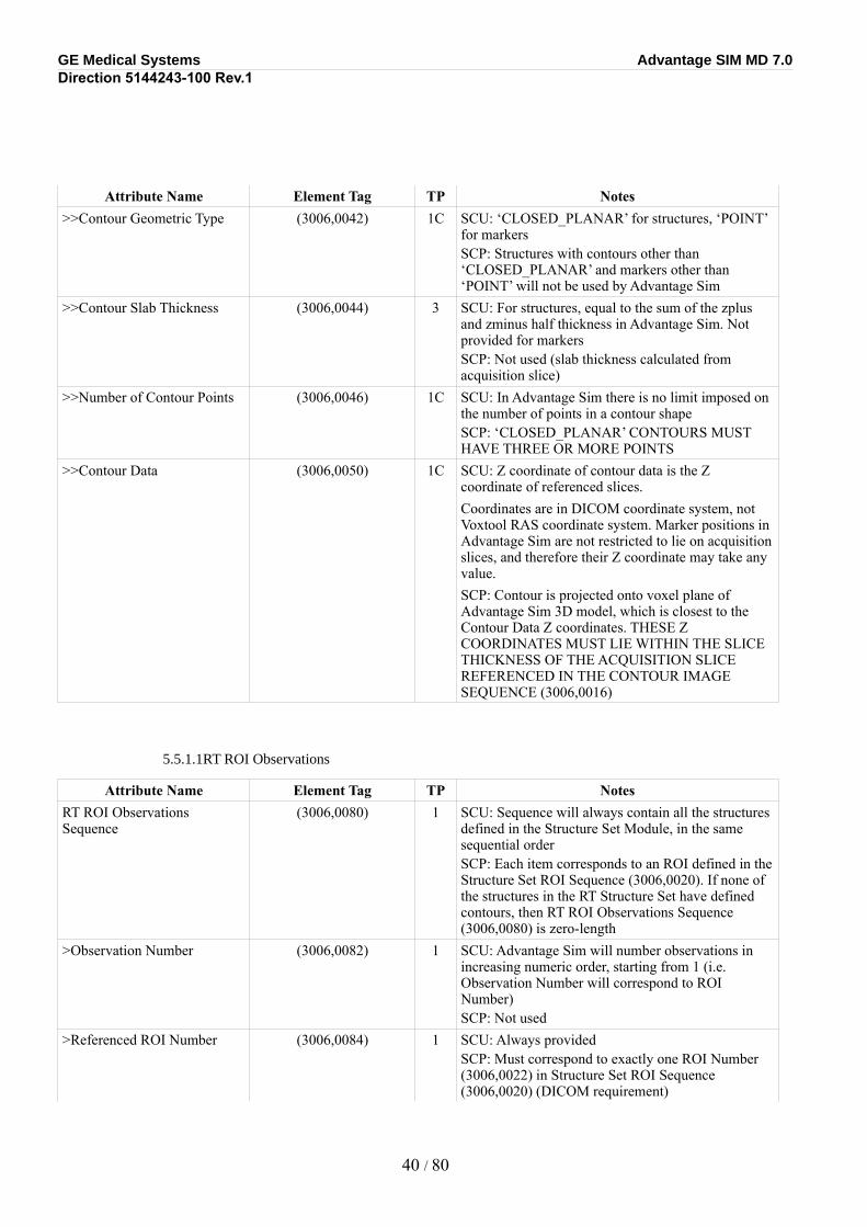
Attribute Name Element Tag TP Notes>>Contour Geometric Type (3006,0042) 1C SCU: ‘CLOSED_PLANAR’ for structures, ‘POINT’
for markersSCP: Structures with contours other than ‘CLOSED_PLANAR’ and markers other than ‘POINT’ will not be used by Advantage Sim
>>Contour Slab Thickness (3006,0044) 3 SCU: For structures, equal to the sum of the zplus and zminus half thickness in Advantage Sim. Not provided for markersSCP: Not used (slab thickness calculated from acquisition slice)
>>Number of Contour Points (3006,0046) 1C SCU: In Advantage Sim there is no limit imposed on the number of points in a contour shapeSCP: ‘CLOSED_PLANAR’ CONTOURS MUST HAVE THREE OR MORE POINTS
>>Contour Data (3006,0050) 1C SCU: Z coordinate of contour data is the Z coordinate of referenced slices.Coordinates are in DICOM coordinate system, not Voxtool RAS coordinate system. Marker positions in Advantage Sim are not restricted to lie on acquisition slices, and therefore their Z coordinate may take any value.SCP: Contour is projected onto voxel plane of Advantage Sim 3D model, which is closest to the Contour Data Z coordinates. THESE Z COORDINATES MUST LIE WITHIN THE SLICE THICKNESS OF THE ACQUISITION SLICE REFERENCED IN THE CONTOUR IMAGE SEQUENCE (3006,0016)
5.5.1.1RT ROI Observations
Attribute Name Element Tag TP NotesRT ROI Observations Sequence
(3006,0080) 1 SCU: Sequence will always contain all the structures defined in the Structure Set Module, in the same sequential orderSCP: Each item corresponds to an ROI defined in the Structure Set ROI Sequence (3006,0020). If none of the structures in the RT Structure Set have defined contours, then RT ROI Observations Sequence (3006,0080) is zero-length
>Observation Number (3006,0082) 1 SCU: Advantage Sim will number observations in increasing numeric order, starting from 1 (i.e. Observation Number will correspond to ROI Number)SCP: Not used
>Referenced ROI Number (3006,0084) 1 SCU: Always providedSCP: Must correspond to exactly one ROI Number (3006,0022) in Structure Set ROI Sequence (3006,0020) (DICOM requirement)
40 / 80
GE Medical Systems Advantage SIM MD 7.0Direction 5144243-100 Rev.1
Attribute Name Element Tag TP Notes>ROI Observation Label (3006,0085) 3 SCU: Equal to Advantage Sim structure name,
truncated to 16 charactersSCP: Not used
>RT ROI Interpreted Type (3006,00A4) 2 SCU: Supported types are EXTERNAL, PTV, CTV, GTV, AVOIDANCE, ORGAN, CONTRAST_AGENT, CAVITY, and MARKER. Will be zero-length if Structure Type is UNKNOWN in Advantage SimSCP: ROIs with an Interpreted Type of ISOCENTER will be converted to MARKER. ROIs with an Interpreted Type other than ISOCENTER or those in the above list will be converted to UNKNOWN
>ROI Interpreter (3006, 00A6) 2 SCU: Zero-lengthSCP: Not used
5.5.1.1SOP Common
Attribute Name Element Tag TP NotesSOP Class UID (0008,0016) 1 SCU: ‘1.2.840.10008.5.1.4.1.1.481.3’
SCP: Must be equal to ‘1.2.840.10008.5.1.4.1.1.481.3’ (DICOM requirement)
SOP Instance UID (0008,0018) 1 SCU: UID root will be ‘1.2.840.113619.2.196’SCP: Used to verify association with RT Plans
Specific Character Set (0008,0005) 1C SCU: ‘ISO_IR 100’SCP: Specific Character Sets other than ‘ISO_IR 100’ are not handled explicitly by Advantage Sim
Instance Creation Date (0008,0012) 3 SCU: Same as Structure Set Date (3006,0008)SCP: Not used
Instance Creation Time (0008,0013) 3 SCU: Same as Structure Set Time (3006,0009)SCP: Not used
Instance Creator UID (0008,0014) 3 SCU: ‘1.2.840.113619.6.196’SCP: If Instance Creator UID corresponds to a version of Advantage Sim, then it is used to prevent loading of old-format RT Structure Sets, otherwise not used
5.6Private Data Dictionary for RT Structure Set
Private Creator Identification GEMS_RTEN_01
Attribute Name Element Tag VR VMGE Attached Contours (see ) (0249,xxC9) IS 1-nCouch Removal Status (0249,xxE0) CS 1View Layout (0249,xxE1) CS 4,8Planar View Windowing (0249,xxE2) IS 2ROI Generation Thresholds (0249,xxE3) IS 2ROI Bridge Removal Pixels (0249,xxE4) IS 1
41 / 80

GE Medical Systems Advantage SIM MD 7.0Direction 5144243-100 Rev.1
Attribute Name Element Tag VR VM3D Model Name (0249,xxE5) CS 1Remove Couch Coordinate (0249,xxE6) CS 1
42 / 80
GE Medical Systems Advantage SIM MD 7.0Direction 5144243-100 Rev.1
SECTION 6RT PLAN INFORMATION OBJECT IMPLEMENTATION (AS SCU) AND REQUIREMENTS (AS SCP)
6.1Introduction
This section specifies the use of the DICOM RT Plan IOD to represent the information included in plans produced by this implementation, and also specifies the requirements for the RT Plan IOD when being used as input to Advantage Sim. Corresponding attributes are conveyed using the module construct.
Advantage Sim implements the RT Plan IOD as a Standard Extended object, containing four additional elements defined in the RT General Plan Module (see Section ), one additional element in the RT Patient Setup Module (see Section ), and eight additional elements in the RT Beams module (see Section ). These thirteen attributes are:
•In the RT General Plan Module:
Macro List (0249,xxF1), storing lists of presets and macros used in the Advantage Sim application;
Print Preferences (0249,xxF3), storing the default settings for the Advantage Sim print function;
Treatment Device Conventions (0249,xxF4), storing the conventions (IEC-1217 or machine-based) used when displaying beam angles and collimator jaws.
•In the RT Patient Setup Module:
Patient Scanned Position (0249,xxF2), storing a copy of the Patient Position (0018,5100) in the acquisition images.
•In the RT Beams Module:
Referenced Machine SOP Class UID (0249,xxC0), and Referenced Machine SOP Instance UID (0249,xxC1) of the GE Private DICOM Treatment Machine object used for the beam;
Group Name (0249,xx51) and Group Properties (0249,xx52), properties of the Advantage Sim beam group;
Associated Markers (0249,xxCA), the list of RT Structure Set markers, which are related to the current beam;
Beam Limiting Device Mode (0249,xxF5), the operating mode of the collimator for the current beam.
DRR Settings (0249,xxF6), the current DRR settings for the current beam;
Conformation Algorithm (0249,xxF7), the conformation algorithm used for the current beam.
43 / 80
GE Medical Systems Advantage SIM MD 7.0Direction 5144243-100 Rev.1
These attributes are provided for enhanced functionality when reading RT Plans created by the Advantage Sim application itself. They should be ignored by SCP implementations interpreting these objects. These attributes are not required in RT Plans created by SCU implementations for use in Advantage Sim.
6.2RT Plan IOD Implementation
This section defines the implementation of the RT Plan information object in the Advantage Sim application. It refers to the DICOM Standard 2000 Part 3 (Information Object Definitions).
In the following tables, notes are provided for when Advantage Sim is acting as a producer of objects (SCU), and a consumer of objects (SCP). Notes in UPPER CASE LETTERS represent restrictions on object contents imposed by Advantage Sim when acting as an SCP (object consumer).
44 / 80
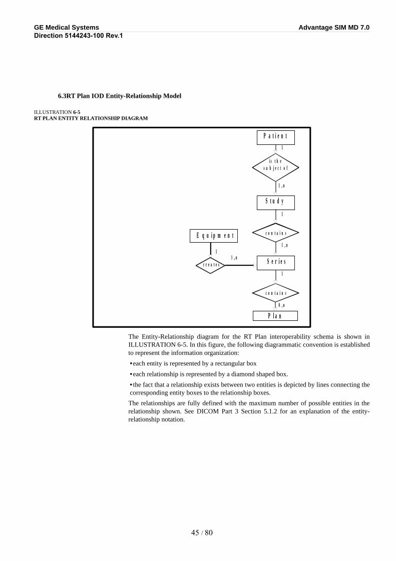
GE Medical Systems Advantage SIM MD 7.0Direction 5144243-100 Rev.1
6.3RT Plan IOD Entity-Relationship Model
ILLUSTRATION 6-5RT PLAN ENTITY RELATIONSHIP DIAGRAM
P a t i e n t
i s t h e s u b j e c t o f
S t u d y
c o n t a i n s
S e r i e s
c o n t a i n s
c r e a t e s
E q u i p m e n t
1
1
1
1
1 , n
1 , n
1 , n
P l a n 0 , n
The Entity-Relationship diagram for the RT Plan interoperability schema is shown in ILLUSTRATION 6-5. In this figure, the following diagrammatic convention is established to represent the information organization:
•each entity is represented by a rectangular box
•each relationship is represented by a diamond shaped box.
•the fact that a relationship exists between two entities is depicted by lines connecting the corresponding entity boxes to the relationship boxes.
The relationships are fully defined with the maximum number of possible entities in the relationship shown. See DICOM Part 3 Section 5.1.2 for an explanation of the entity-relationship notation.
45 / 80
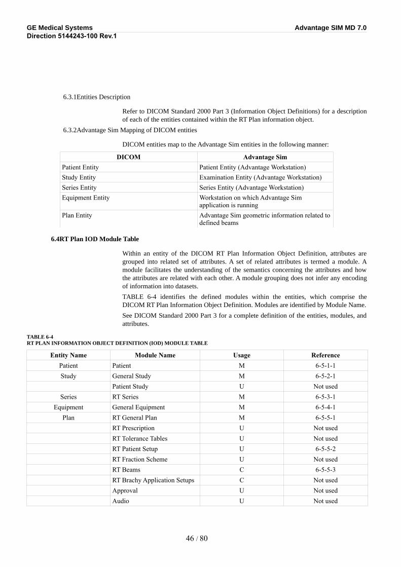
GE Medical Systems Advantage SIM MD 7.0Direction 5144243-100 Rev.1
6.3.1Entities Description
Refer to DICOM Standard 2000 Part 3 (Information Object Definitions) for a description of each of the entities contained within the RT Plan information object.
6.3.2Advantage Sim Mapping of DICOM entities
DICOM entities map to the Advantage Sim entities in the following manner:
DICOM Advantage SimPatient Entity Patient Entity (Advantage Workstation)Study Entity Examination Entity (Advantage Workstation)Series Entity Series Entity (Advantage Workstation)Equipment Entity Workstation on which Advantage Sim
application is runningPlan Entity Advantage Sim geometric information related to
defined beams
6.4RT Plan IOD Module Table
Within an entity of the DICOM RT Plan Information Object Definition, attributes are grouped into related set of attributes. A set of related attributes is termed a module. A module facilitates the understanding of the semantics concerning the attributes and how the attributes are related with each other. A module grouping does not infer any encoding of information into datasets.
TABLE 6-4 identifies the defined modules within the entities, which comprise the DICOM RT Plan Information Object Definition. Modules are identified by Module Name.
See DICOM Standard 2000 Part 3 for a complete definition of the entities, modules, and attributes.
TABLE 6-4RT PLAN INFORMATION OBJECT DEFINITION (IOD) MODULE TABLE
Entity Name Module Name Usage ReferencePatient Patient M 6-5-1-1Study General Study M 6-5-2-1
Patient Study U Not usedSeries RT Series M 6-5-3-1
Equipment General Equipment M 6-5-4-1Plan RT General Plan M 6-5-5-1
RT Prescription U Not usedRT Tolerance Tables U Not usedRT Patient Setup U 6-5-5-2RT Fraction Scheme U Not usedRT Beams C 6-5-5-3RT Brachy Application Setups C Not usedApproval U Not usedAudio U Not used
46 / 80
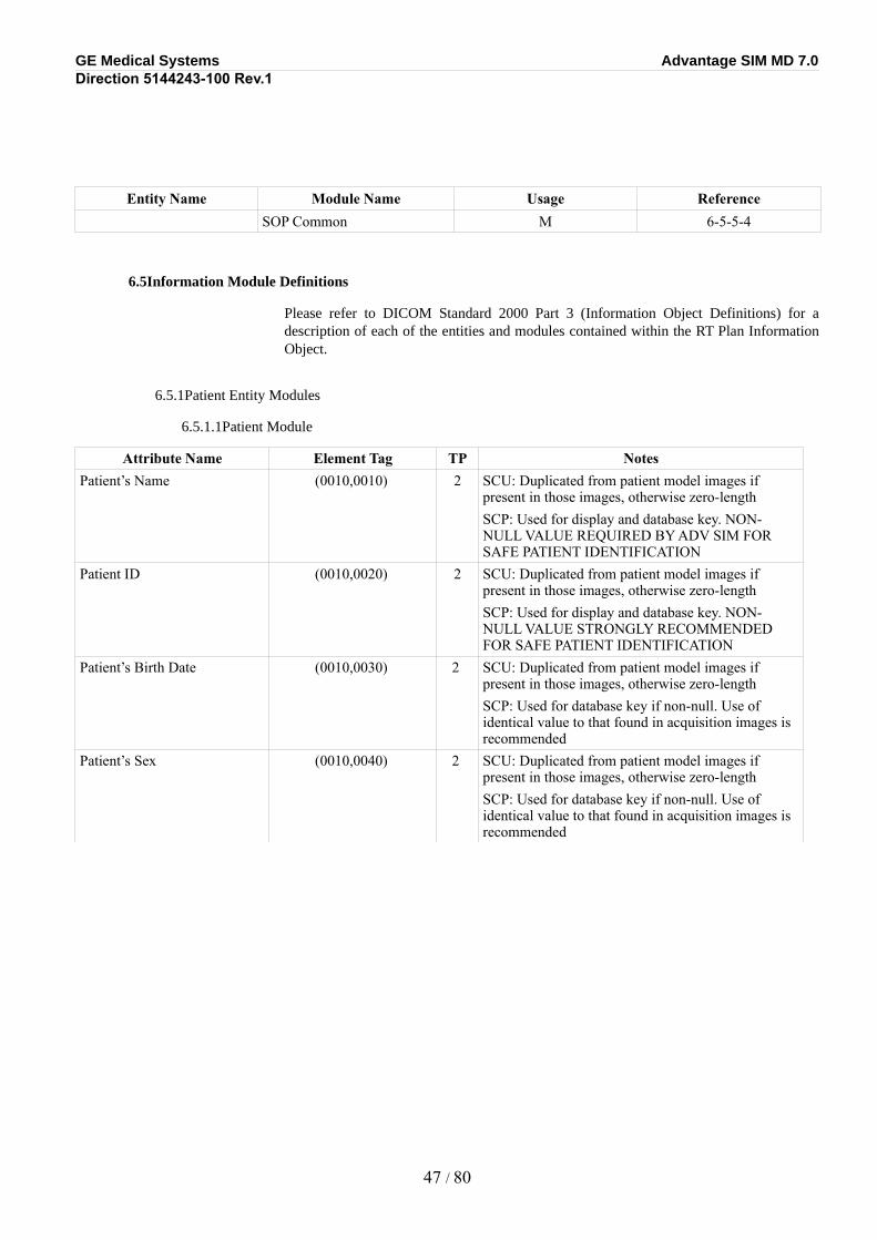
GE Medical Systems Advantage SIM MD 7.0Direction 5144243-100 Rev.1
Entity Name Module Name Usage ReferenceSOP Common M 6-5-5-4
6.5Information Module Definitions
Please refer to DICOM Standard 2000 Part 3 (Information Object Definitions) for a description of each of the entities and modules contained within the RT Plan Information Object.
6.5.1Patient Entity Modules
6.5.1.1Patient Module
Attribute Name Element Tag TP NotesPatient’s Name (0010,0010) 2 SCU: Duplicated from patient model images if
present in those images, otherwise zero-lengthSCP: Used for display and database key. NON-NULL VALUE REQUIRED BY ADV SIM FOR SAFE PATIENT IDENTIFICATION
Patient ID (0010,0020) 2 SCU: Duplicated from patient model images if present in those images, otherwise zero-lengthSCP: Used for display and database key. NON-NULL VALUE STRONGLY RECOMMENDED FOR SAFE PATIENT IDENTIFICATION
Patient’s Birth Date (0010,0030) 2 SCU: Duplicated from patient model images if present in those images, otherwise zero-lengthSCP: Used for database key if non-null. Use of identical value to that found in acquisition images is recommended
Patient’s Sex (0010,0040) 2 SCU: Duplicated from patient model images if present in those images, otherwise zero-lengthSCP: Used for database key if non-null. Use of identical value to that found in acquisition images is recommended
47 / 80
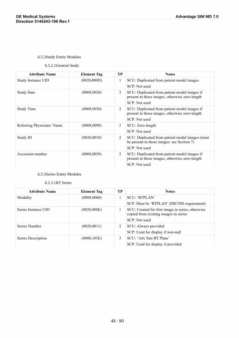
GE Medical Systems Advantage SIM MD 7.0Direction 5144243-100 Rev.1
6.5.2Study Entity Modules
6.5.2.1General Study
Attribute Name Element Tag TP NotesStudy Instance UID (0020,000D) 1 SCU: Duplicated from patient model images
SCP: Not usedStudy Date (0008,0020) 2 SCU: Duplicated from patient model images if
present in those images, otherwise zero-lengthSCP: Not used
Study Time (0008,0030) 2 SCU: Duplicated from patient model images if present in those images, otherwise zero-lengthSCP: Not used
Referring Physicians’ Name (0008,0090) 2 SCU: Zero-lengthSCP: Not used
Study ID (0020,0010) 2 SCU: Duplicated from patient model images (must be present in those images: see Section 7)SCP: Not used
Accession number (0008,0050) 2 SCU: Duplicated from patient model images if present in those images, otherwise zero-lengthSCP: Not used
6.5.3Series Entity Modules
6.5.3.1RT Series
Attribute Name Element Tag TP NotesModality (0008,0060) 1 SCU: ‘RTPLAN’
SCP: Must be ‘RTPLAN’ (DICOM requirement)Series Instance UID (0020,000E) 1 SCU: Created for first image in series, otherwise
copied from existing images in seriesSCP: Not used
Series Number (0020,0011) 2 SCU: Always providedSCP: Used for display if non-null
Series Description (0008,103E) 3 SCU: ‘Adv Sim RT Plans’SCP: Used for display if provided
48 / 80
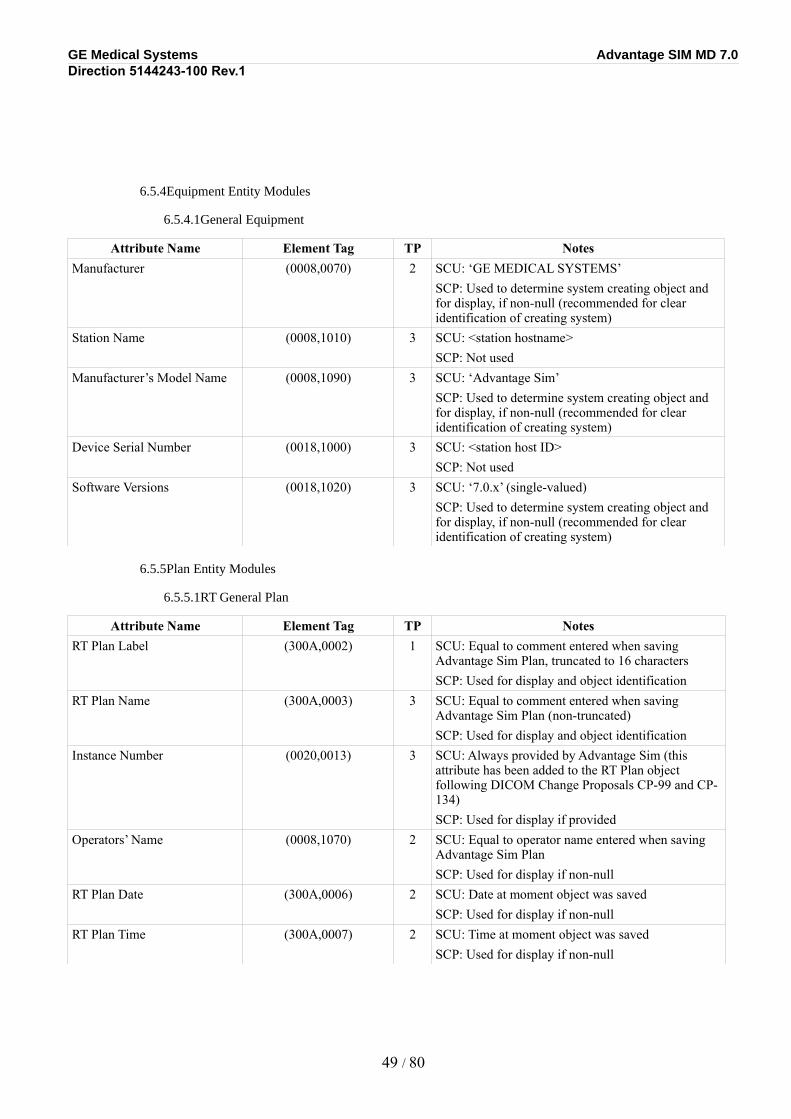
GE Medical Systems Advantage SIM MD 7.0Direction 5144243-100 Rev.1
6.5.4Equipment Entity Modules
6.5.4.1General Equipment
Attribute Name Element Tag TP NotesManufacturer (0008,0070) 2 SCU: ‘GE MEDICAL SYSTEMS’
SCP: Used to determine system creating object and for display, if non-null (recommended for clear identification of creating system)
Station Name (0008,1010) 3 SCU: <station hostname> SCP: Not used
Manufacturer’s Model Name (0008,1090) 3 SCU: ‘Advantage Sim’SCP: Used to determine system creating object and for display, if non-null (recommended for clear identification of creating system)
Device Serial Number (0018,1000) 3 SCU: <station host ID>SCP: Not used
Software Versions (0018,1020) 3 SCU: ‘7.0.x’ (single-valued)SCP: Used to determine system creating object and for display, if non-null (recommended for clear identification of creating system)
6.5.5Plan Entity Modules
6.5.5.1RT General Plan
Attribute Name Element Tag TP NotesRT Plan Label (300A,0002) 1 SCU: Equal to comment entered when saving
Advantage Sim Plan, truncated to 16 charactersSCP: Used for display and object identification
RT Plan Name (300A,0003) 3 SCU: Equal to comment entered when saving Advantage Sim Plan (non-truncated)SCP: Used for display and object identification
Instance Number (0020,0013) 3 SCU: Always provided by Advantage Sim (this attribute has been added to the RT Plan object following DICOM Change Proposals CP-99 and CP-134)SCP: Used for display if provided
Operators’ Name (0008,1070) 2 SCU: Equal to operator name entered when saving Advantage Sim PlanSCP: Used for display if non-null
RT Plan Date (300A,0006) 2 SCU: Date at moment object was savedSCP: Used for display if non-null
RT Plan Time (300A,0007) 2 SCU: Time at moment object was savedSCP: Used for display if non-null
49 / 80
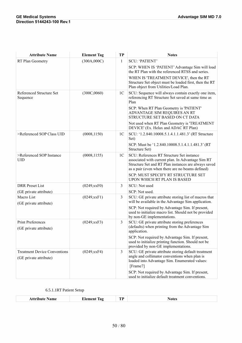
GE Medical Systems Advantage SIM MD 7.0Direction 5144243-100 Rev.1
Attribute Name Element Tag TP NotesRT Plan Geometry (300A,000C) 1 SCU: ‘PATIENT’
SCP: WHEN IS ‘PATIENT’ Advantage Sim will load the RT Plan with the referenced RTSS and series.WHEN IS 'TREATMENT DEVICE', then the RT Structure Set object must be loaded first, then the RT Plan object from Utilities/Load Plan.
Referenced Structure Set Sequence
(300C,0060) 1C SCU: Sequence will always contain exactly one item, referencing RT Structure Set saved at same time as PlanSCP: When RT Plan Geometry is 'PATIENT' ADVANTAGE SIM REQUIRES AN RT STRUCTURE SET BASED ON CT DATANot used when RT Plan Geometry is 'TREATMENT DEVICE' (Ex. Helax and ADAC RT Plan)
>Referenced SOP Class UID (0008,1150) 1C SCU: ‘1.2.840.10008.5.1.4.1.1.481.3’ (RT Structure Set)SCP: Must be ‘1.2.840.10008.5.1.4.1.1.481.3’ (RT Structure Set)
>Referenced SOP Instance UID
(0008,1155) 1C SCU: References RT Structure Set instance associated with current plan. In Advantage Sim RT Structure Set and RT Plan instances are always saved as a pair (even when there are no beams defined)SCP: MUST SPECIFY RT STRUCTURE SET UPON WHICH RT PLAN IS BASED
DRR Preset List(GE private attribute)
(0249,xxF0) 3 SCU: Not usedSCP: Not used.
Macro List(GE private attribute)
(0249,xxF1) 3 SCU: GE private attribute storing list of macros that will be available in the Advantage Sim application.SCP: Not required by Advantage Sim. If present, used to initialize macro list. Should not be provided by non-GE implementations.
Print Preferences(GE private attribute)
(0249,xxF3) 3 SCU: GE private attribute storing preferences (defaults) when printing from the Advantage Sim application.SCP: Not required by Advantage Sim. If present, used to initialize printing function. Should not be provided by non-GE implementations.
Treatment Device Conventions(GE private attribute)
(0249,xxF4) 3 SCU: GE private attribute storing default treatment angle and collimator conventions when plan is loaded into Advantage Sim. Enumerated values: [Frame7] SCP: Not required by Advantage Sim. If present, used to initialize default treatment conventions.
6.5.1.1RT Patient Setup
Attribute Name Element Tag TP Notes
50 / 80
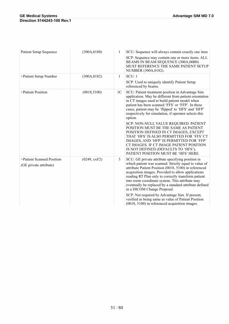
GE Medical Systems Advantage SIM MD 7.0Direction 5144243-100 Rev.1
Patient Setup Sequence (300A,0180) 1 SCU: Sequence will always contain exactly one itemSCP: Sequence may contain one or more items. ALL BEAMS IN BEAM SEQUENCE (300A,00B0) MUST REFERENCE THE SAME PATIENT SETUP NUMBER (300A,0182).
>Patient Setup Number (300A,0182) 1 SCU: 1SCP: Used to uniquely identify Patient Setup referenced by beams.
>Patient Position (0018,5100) 1C SCU: Patient treatment position in Advantage Sim application. May be different from patient orientation in CT images used to build patient model when patient has been scanned ‘FFS’ or ‘FFP’. In these cases, patient may be ‘flipped’ to ‘HFS’ and ‘HFP’ respectively for simulation, if operator selects this option.SCP: NON-NULL VALUE REQUIRED. PATIENT POSITION MUST BE THE SAME AS PATIENT POSITION DEFINED IN CT IMAGES, EXCEPT THAT ‘HFS’ IS ALSO PERMITTED FOR ‘FFS’ CT IMAGES, AND ‘HFP’ IS PERMITTED FOR ‘FFP’ CT IMAGES. IF CT IMAGE PATIENT POSITION IS NOT DEFINED (DEFAULTS TO ‘HFS’), PATIENT POSITION MUST BE ‘HFS’ HERE.
>Patient Scanned Position(GE private attribute)
(0249, xxF2) 3 SCU: GE private attribute specifying position in which patient was scanned. Strictly equal to value of attribute Patient Position (0018, 5100) in referenced acquisition images. Provided to allow applications reading RT Plan only to correctly transform patient into room coordinate system. This attribute may eventually be replaced by a standard attribute defined in a DICOM Change Proposal.SCP: Not required by Advantage Sim. If present, verified as being same as value of Patient Position (0018, 5100) in referenced acquisition images.
51 / 80
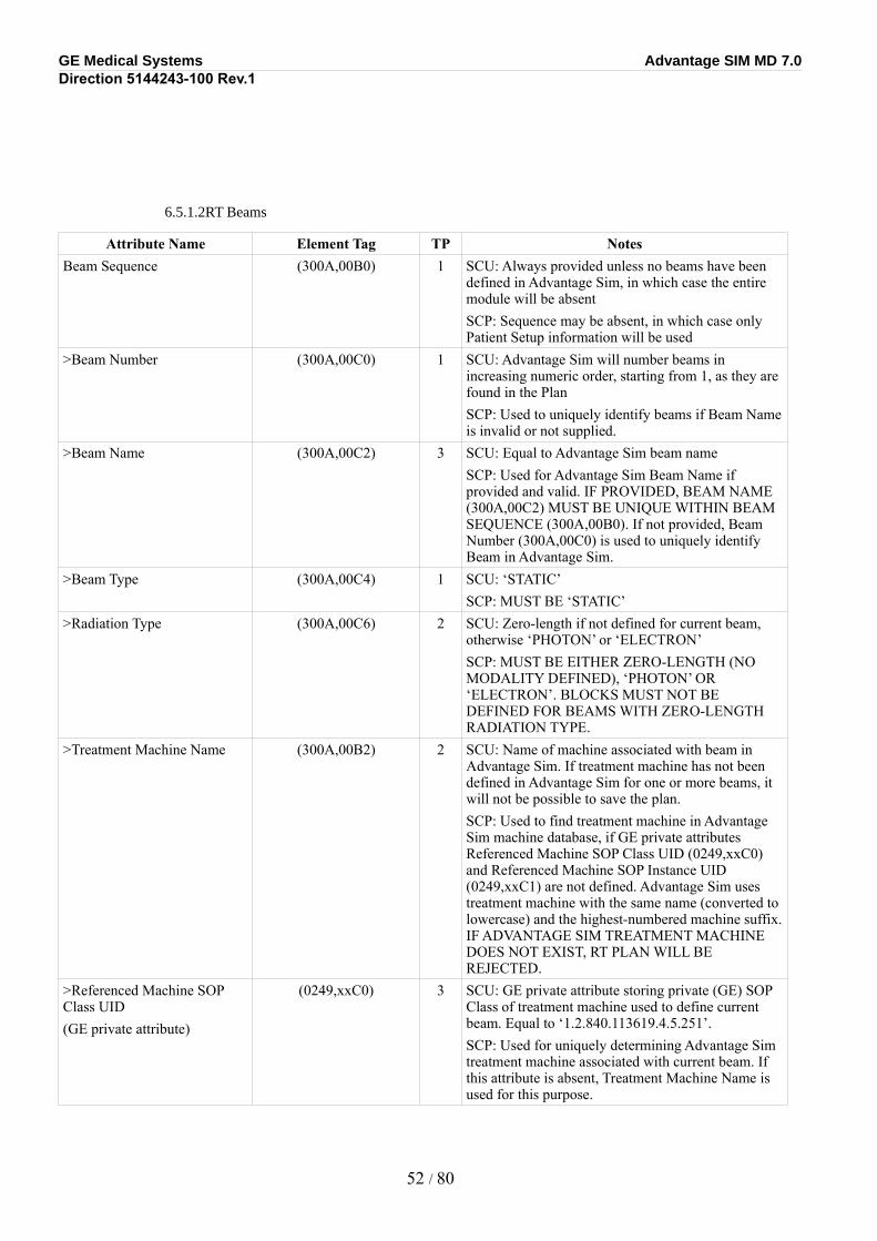
GE Medical Systems Advantage SIM MD 7.0Direction 5144243-100 Rev.1
6.5.1.2RT Beams
Attribute Name Element Tag TP NotesBeam Sequence (300A,00B0) 1 SCU: Always provided unless no beams have been
defined in Advantage Sim, in which case the entire module will be absentSCP: Sequence may be absent, in which case only Patient Setup information will be used
>Beam Number (300A,00C0) 1 SCU: Advantage Sim will number beams in increasing numeric order, starting from 1, as they are found in the PlanSCP: Used to uniquely identify beams if Beam Name is invalid or not supplied.
>Beam Name (300A,00C2) 3 SCU: Equal to Advantage Sim beam nameSCP: Used for Advantage Sim Beam Name if provided and valid. IF PROVIDED, BEAM NAME (300A,00C2) MUST BE UNIQUE WITHIN BEAM SEQUENCE (300A,00B0). If not provided, Beam Number (300A,00C0) is used to uniquely identify Beam in Advantage Sim.
>Beam Type (300A,00C4) 1 SCU: ‘STATIC’SCP: MUST BE ‘STATIC’
>Radiation Type (300A,00C6) 2 SCU: Zero-length if not defined for current beam, otherwise ‘PHOTON’ or ‘ELECTRON’SCP: MUST BE EITHER ZERO-LENGTH (NO MODALITY DEFINED), ‘PHOTON’ OR ‘ELECTRON’. BLOCKS MUST NOT BE DEFINED FOR BEAMS WITH ZERO-LENGTH RADIATION TYPE.
>Treatment Machine Name (300A,00B2) 2 SCU: Name of machine associated with beam in Advantage Sim. If treatment machine has not been defined in Advantage Sim for one or more beams, it will not be possible to save the plan.SCP: Used to find treatment machine in Advantage Sim machine database, if GE private attributes Referenced Machine SOP Class UID (0249,xxC0) and Referenced Machine SOP Instance UID (0249,xxC1) are not defined. Advantage Sim uses treatment machine with the same name (converted to lowercase) and the highest-numbered machine suffix. IF ADVANTAGE SIM TREATMENT MACHINE DOES NOT EXIST, RT PLAN WILL BE REJECTED.
>Referenced Machine SOP Class UID(GE private attribute)
(0249,xxC0) 3 SCU: GE private attribute storing private (GE) SOP Class of treatment machine used to define current beam. Equal to ‘1.2.840.113619.4.5.251’.SCP: Used for uniquely determining Advantage Sim treatment machine associated with current beam. If this attribute is absent, Treatment Machine Name is used for this purpose.
52 / 80
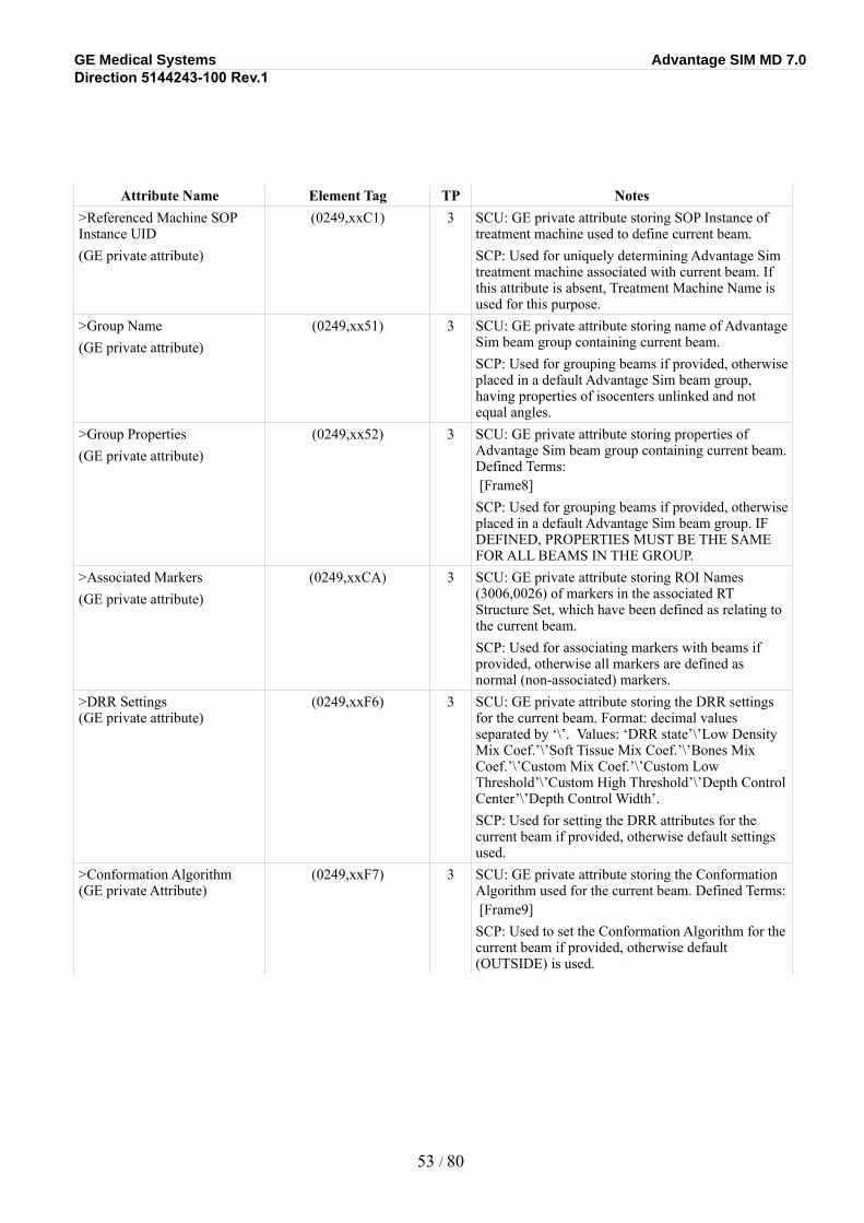
GE Medical Systems Advantage SIM MD 7.0Direction 5144243-100 Rev.1
Attribute Name Element Tag TP Notes>Referenced Machine SOP Instance UID(GE private attribute)
(0249,xxC1) 3 SCU: GE private attribute storing SOP Instance of treatment machine used to define current beam.SCP: Used for uniquely determining Advantage Sim treatment machine associated with current beam. If this attribute is absent, Treatment Machine Name is used for this purpose.
>Group Name(GE private attribute)
(0249,xx51) 3 SCU: GE private attribute storing name of Advantage Sim beam group containing current beam.SCP: Used for grouping beams if provided, otherwise placed in a default Advantage Sim beam group, having properties of isocenters unlinked and not equal angles.
>Group Properties(GE private attribute)
(0249,xx52) 3 SCU: GE private attribute storing properties of Advantage Sim beam group containing current beam. Defined Terms: [Frame8] SCP: Used for grouping beams if provided, otherwise placed in a default Advantage Sim beam group. IF DEFINED, PROPERTIES MUST BE THE SAME FOR ALL BEAMS IN THE GROUP.
>Associated Markers(GE private attribute)
(0249,xxCA) 3 SCU: GE private attribute storing ROI Names (3006,0026) of markers in the associated RT Structure Set, which have been defined as relating to the current beam.SCP: Used for associating markers with beams if provided, otherwise all markers are defined as normal (non-associated) markers.
>DRR Settings (GE private attribute)
(0249,xxF6) 3 SCU: GE private attribute storing the DRR settings for the current beam. Format: decimal values separated by ‘\’. Values: ‘DRR state’\’Low Density Mix Coef.’\’Soft Tissue Mix Coef.’\’Bones Mix Coef.’\’Custom Mix Coef.’\’Custom Low Threshold’\’Custom High Threshold’\’Depth Control Center’\’Depth Control Width’.SCP: Used for setting the DRR attributes for the current beam if provided, otherwise default settings used.
>Conformation Algorithm(GE private Attribute)
(0249,xxF7) 3 SCU: GE private attribute storing the Conformation Algorithm used for the current beam. Defined Terms: [Frame9] SCP: Used to set the Conformation Algorithm for the current beam if provided, otherwise default (OUTSIDE) is used.
53 / 80
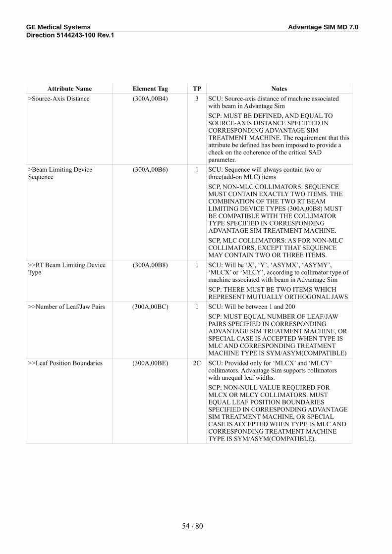
GE Medical Systems Advantage SIM MD 7.0Direction 5144243-100 Rev.1
Attribute Name Element Tag TP Notes>Source-Axis Distance (300A,00B4) 3 SCU: Source-axis distance of machine associated
with beam in Advantage SimSCP: MUST BE DEFINED, AND EQUAL TO SOURCE-AXIS DISTANCE SPECIFIED IN CORRESPONDING ADVANTAGE SIM TREATMENT MACHINE. The requirement that this attribute be defined has been imposed to provide a check on the coherence of the critical SAD parameter.
>Beam Limiting Device Sequence
(300A,00B6) 1 SCU: Sequence will always contain two or three(add-on MLC) itemsSCP, NON-MLC COLLIMATORS: SEQUENCE MUST CONTAIN EXACTLY TWO ITEMS. THE COMBINATION OF THE TWO RT BEAM LIMITING DEVICE TYPES (300A,00B8) MUST BE COMPATIBLE WITH THE COLLIMATOR TYPE SPECIFIED IN CORRESPONDING ADVANTAGE SIM TREATMENT MACHINE.SCP, MLC COLLIMATORS: AS FOR NON-MLC COLLIMATORS, EXCEPT THAT SEQUENCE MAY CONTAIN TWO OR THREE ITEMS.
>>RT Beam Limiting Device Type
(300A,00B8) 1 SCU: Will be ‘X’, ‘Y’, ‘ASYMX’, ‘ASYMY’, ‘MLCX’ or ‘MLCY’, according to collimator type of machine associated with beam in Advantage SimSCP: THERE MUST BE TWO ITEMS WHICH REPRESENT MUTUALLY ORTHOGONAL JAWS
>>Number of Leaf/Jaw Pairs (300A,00BC) 1 SCU: Will be between 1 and 200SCP: MUST EQUAL NUMBER OF LEAF/JAW PAIRS SPECIFIED IN CORRESPONDING ADVANTAGE SIM TREATMENT MACHINE, OR SPECIAL CASE IS ACCEPTED WHEN TYPE IS MLC AND CORRESPONDING TREATMENT MACHINE TYPE IS SYM/ASYM(COMPATIBLE)
>>Leaf Position Boundaries (300A,00BE) 2C SCU: Provided only for ‘MLCX’ and ‘MLCY’ collimators. Advantage Sim supports collimators with unequal leaf widths.SCP: NON-NULL VALUE REQUIRED FOR MLCX OR MLCY COLLIMATORS. MUST EQUAL LEAF POSITION BOUNDARIES SPECIFIED IN CORRESPONDING ADVANTAGE SIM TREATMENT MACHINE, OR SPECIAL CASE IS ACCEPTED WHEN TYPE IS MLC AND CORRESPONDING TREATMENT MACHINE TYPE IS SYM/ASYM(COMPATIBLE).
54 / 80
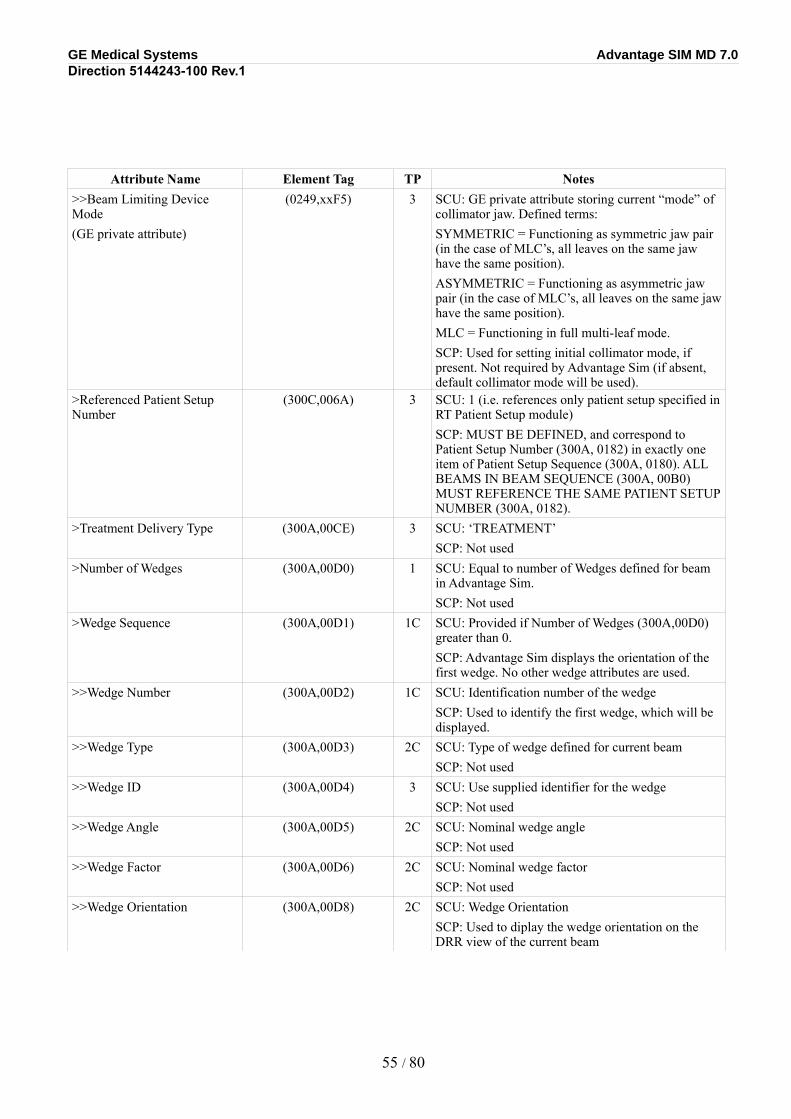
GE Medical Systems Advantage SIM MD 7.0Direction 5144243-100 Rev.1
Attribute Name Element Tag TP Notes>>Beam Limiting Device Mode(GE private attribute)
(0249,xxF5) 3 SCU: GE private attribute storing current “mode” of collimator jaw. Defined terms:SYMMETRIC = Functioning as symmetric jaw pair (in the case of MLC’s, all leaves on the same jaw have the same position).ASYMMETRIC = Functioning as asymmetric jaw pair (in the case of MLC’s, all leaves on the same jaw have the same position).MLC = Functioning in full multi-leaf mode.SCP: Used for setting initial collimator mode, if present. Not required by Advantage Sim (if absent, default collimator mode will be used).
>Referenced Patient Setup Number
(300C,006A) 3 SCU: 1 (i.e. references only patient setup specified in RT Patient Setup module)SCP: MUST BE DEFINED, and correspond to Patient Setup Number (300A, 0182) in exactly one item of Patient Setup Sequence (300A, 0180). ALL BEAMS IN BEAM SEQUENCE (300A, 00B0) MUST REFERENCE THE SAME PATIENT SETUP NUMBER (300A, 0182).
>Treatment Delivery Type (300A,00CE) 3 SCU: ‘TREATMENT’SCP: Not used
>Number of Wedges (300A,00D0) 1 SCU: Equal to number of Wedges defined for beam in Advantage Sim.SCP: Not used
>Wedge Sequence (300A,00D1) 1C SCU: Provided if Number of Wedges (300A,00D0) greater than 0.SCP: Advantage Sim displays the orientation of the first wedge. No other wedge attributes are used.
>>Wedge Number (300A,00D2) 1C SCU: Identification number of the wedgeSCP: Used to identify the first wedge, which will be displayed.
>>Wedge Type (300A,00D3) 2C SCU: Type of wedge defined for current beamSCP: Not used
>>Wedge ID (300A,00D4) 3 SCU: Use supplied identifier for the wedgeSCP: Not used
>>Wedge Angle (300A,00D5) 2C SCU: Nominal wedge angleSCP: Not used
>>Wedge Factor (300A,00D6) 2C SCU: Nominal wedge factorSCP: Not used
>>Wedge Orientation (300A,00D8) 2C SCU: Wedge OrientationSCP: Used to diplay the wedge orientation on the DRR view of the current beam
55 / 80
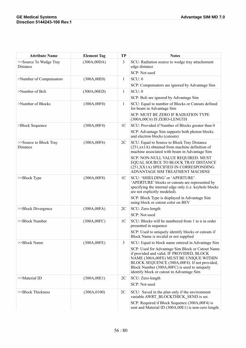
GE Medical Systems Advantage SIM MD 7.0Direction 5144243-100 Rev.1
Attribute Name Element Tag TP Notes>>Source To Wedge Tray Distance
(300A,00DA) 3 SCU: Radiation source to wedge tray attachement edge distanceSCP: Not used
>Number of Compensators (300A,00E0) 1 SCU: 0SCP: Compensators are ignored by Advantage Sim
>Number of Boli (300A,00ED) 1 SCU: 0SCP: Boli are ignored by Advantage Sim
>Number of Blocks (300A,00F0) 1 SCU: Equal to number of Blocks or Cutouts defined for beam in Advantage SimSCP: MUST BE ZERO IF RADIATION TYPE (300A,00C6) IS ZERO-LENGTH
>Block Sequence (300A,00F4) 1C SCU: Provided if Number of Blocks greater than 0SCP: Advantage Sim supports both photon blocks and electron blocks (cutouts)
>>Source to Block Tray Distance
(300A,00F6) 2C SCU: Equal to Source to Block Tray Distance (251,xx1A) obtained from machine definition of machine associated with beam in Advantage SimSCP: NON-NULL VALUE REQUIRED. MUST EQUAL SOURCE TO BLOCK TRAY DISTANCE (251,XX1A) SPECIFIED IN CORRESPONDING ADVANTAGE SIM TREATMENT MACHINE
>>Block Type (300A,00F8) 1C SCU: ‘SHIELDING’ or ‘APERTURE’. ‘APERTURE’ blocks or cutouts are represented by specifying the internal edge only (i.e. keyhole blocks are not explicitly modeled).SCP: Block Type is displayed in Advantage Sim using block or cutout color on BEV
>>Block Divergence (300A,00FA) 2C SCU: Zero-lengthSCP: Not used
>>Block Number (300A,00FC) 1C SCU: Blocks will be numbered from 1 to n in order presented in sequenceSCP: Used to uniquely identify blocks or cutouts if Block Name is invalid or not supplied
>>Block Name (300A,00FE) 3 SCU: Equal to block name entered in Advantage SimSCP: Used for Advantage Sim Block or Cutout Name if provided and valid. IF PROVIDED, BLOCK NAME (300A,00FE) MUST BE UNIQUE WITHIN BLOCK SEQUENCE (300A,00F4). If not provided, Block Number (300A,00FC) is used to uniquely identify block or cutout in Advantage Sim
>>Material ID (300A,00E1) 2C SCU: Zero-lengthSCP: Not used
>>Block Thickness (300A,0100) 2C SCU: Saved in the plan only if the environment variable AWRT_BLOCKTHICK_SEND is set.SCP: Required if Block Sequence (300A,00F4) is sent and Material ID (300A,00E1) is non-zero length.
56 / 80
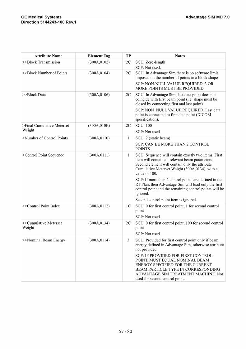
GE Medical Systems Advantage SIM MD 7.0Direction 5144243-100 Rev.1
Attribute Name Element Tag TP Notes>>Block Transmission (300A,0102) 2C SCU: Zero-length
SCP: Not used.>>Block Number of Points (300A,0104) 2C SCU: In Advantage Sim there is no software limit
imposed on the number of points in a block shapeSCP: NON-NULL VALUE REQUIRED. 3 OR MORE POINTS MUST BE PROVIDED
>>Block Data (300A,0106) 2C SCU: In Advantage Sim, last data point does not coincide with first beam point (i.e. shape must be closed by connecting first and last point).SCP: NON_NULL VALUE REQUIRED. Last data point is connected to first data point (DICOM specification).
>Final Cumulative Meterset Weight
(300A,010E) 2C SCU: 100SCP: Not used
>Number of Control Points (300A,0110) 1 SCU: 2 (static beam)SCP: CAN BE MORE THAN 2 CONTROL POINTS.
>Control Point Sequence (300A,0111) 1 SCU: Sequence will contain exactly two items. First item will contain all relevant beam parameters. Second element will contain only the attribute Cumulative Meterset Weight (300A,0134), with a value of 100.SCP: If more than 2 control points are defined in the RT Plan, then Advantage Sim will load only the first control point and the remaining control points will be ignored.Second control point item is ignored.
>>Control Point Index (300A,0112) 1C SCU: 0 for first control point, 1 for second control pointSCP: Not used
>>Cumulative Meterset Weight
(300A,0134) 2C SCU: 0 for first control point, 100 for second control pointSCP: Not used
>>Nominal Beam Energy (300A,0114) 3 SCU: Provided for first control point only if beam energy defined in Advantage Sim, otherwise attribute not providedSCP: IF PROVIDED FOR FIRST CONTROL POINT, MUST EQUAL NOMINAL BEAM ENERGY SPECIFIED FOR THE CURRENT BEAM PARTICLE TYPE IN CORRESPONDING ADVANTAGE SIM TREATMENT MACHINE. Not used for second control point.
57 / 80
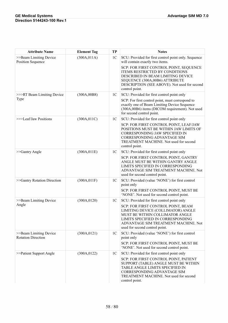
GE Medical Systems Advantage SIM MD 7.0Direction 5144243-100 Rev.1
Attribute Name Element Tag TP Notes>>Beam Limiting Device Position Sequence
(300A,011A) 1C SCU: Provided for first control point only. Sequence will contain exactly two items.SCP: FOR FIRST CONTROL POINT, SEQUENCE ITEMS RESTRICTED BY CONDITIONS DESCRIBED IN BEAM LIMITING DEVICE SEQUENCE (300A,00B6) ATTRIBUTE DESCRIPTION (SEE ABOVE). Not used for second control point.
>>>RT Beam Limiting Device Type
(300A,00B8) 1C SCU: Provided for first control point onlySCP: For first control point, must correspond to exactly one of Beam Limiting Device Sequence (300A,00B6) items (DICOM requirement). Not used for second control point.
>>>Leaf/Jaw Positions (300A,011C) 1C SCU: Provided for first control point onlySCP: FOR FIRST CONTROL POINT, LEAF/JAW POSITIONS MUST BE WITHIN JAW LIMITS OF CORRESPONDING JAW SPECIFIED IN CORRESPONDING ADVANTAGE SIM TREATMENT MACHINE. Not used for second control point.
>>Gantry Angle (300A,011E) 1C SCU: Provided for first control point onlySCP: FOR FIRST CONTROL POINT, GANTRY ANGLE MUST BE WITHIN GANTRY ANGLE LIMITS SPECIFIED IN CORRESPONDING ADVANTAGE SIM TREATMENT MACHINE. Not used for second control point.
>>Gantry Rotation Direction (300A,011F) 1C SCU: Provided (value ‘NONE’) for first control point onlySCP: FOR FIRST CONTROL POINT, MUST BE ‘NONE’. Not used for second control point.
>>Beam Limiting Device Angle
(300A,0120) 1C SCU: Provided for first control point onlySCP: FOR FIRST CONTROL POINT, BEAM LIMITING DEVICE (COLLIMATOR) ANGLE MUST BE WITHIN COLLIMATOR ANGLE LIMITS SPECIFIED IN CORRESPONDING ADVANTAGE SIM TREATMENT MACHINE. Not used for second control point.
>>Beam Limiting Device Rotation Direction
(300A,0121) 1C SCU: Provided (value ‘NONE’) for first control point onlySCP: FOR FIRST CONTROL POINT, MUST BE ‘NONE’. Not used for second control point.
>>Patient Support Angle (300A,0122) 1C SCU: Provided for first control point onlySCP: FOR FIRST CONTROL POINT, PATIENT SUPPORT (TABLE) ANGLE MUST BE WITHIN TABLE ANGLE LIMITS SPECIFIED IN CORRESPONDING ADVANTAGE SIM TREATMENT MACHINE. Not used for second control point.
58 / 80
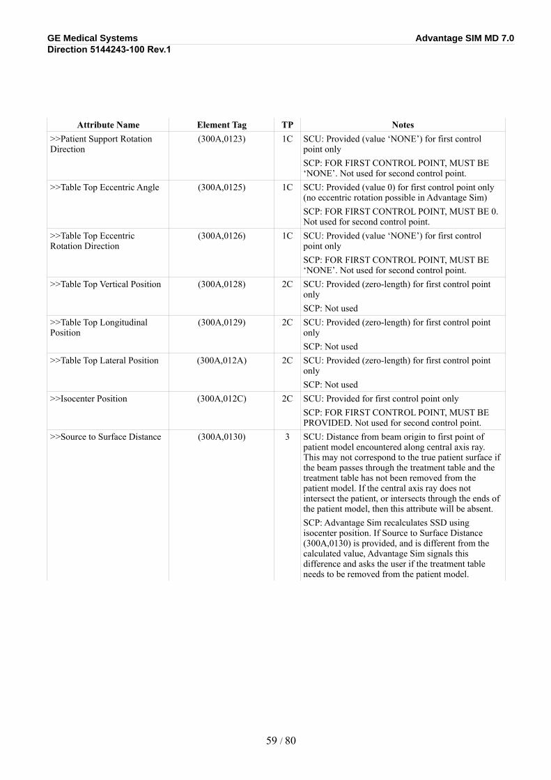
GE Medical Systems Advantage SIM MD 7.0Direction 5144243-100 Rev.1
Attribute Name Element Tag TP Notes>>Patient Support Rotation Direction
(300A,0123) 1C SCU: Provided (value ‘NONE’) for first control point onlySCP: FOR FIRST CONTROL POINT, MUST BE ‘NONE’. Not used for second control point.
>>Table Top Eccentric Angle (300A,0125) 1C SCU: Provided (value 0) for first control point only (no eccentric rotation possible in Advantage Sim)SCP: FOR FIRST CONTROL POINT, MUST BE 0. Not used for second control point.
>>Table Top Eccentric Rotation Direction
(300A,0126) 1C SCU: Provided (value ‘NONE’) for first control point onlySCP: FOR FIRST CONTROL POINT, MUST BE ‘NONE’. Not used for second control point.
>>Table Top Vertical Position (300A,0128) 2C SCU: Provided (zero-length) for first control point onlySCP: Not used
>>Table Top Longitudinal Position
(300A,0129) 2C SCU: Provided (zero-length) for first control point onlySCP: Not used
>>Table Top Lateral Position (300A,012A) 2C SCU: Provided (zero-length) for first control point onlySCP: Not used
>>Isocenter Position (300A,012C) 2C SCU: Provided for first control point onlySCP: FOR FIRST CONTROL POINT, MUST BE PROVIDED. Not used for second control point.
>>Source to Surface Distance (300A,0130) 3 SCU: Distance from beam origin to first point of patient model encountered along central axis ray. This may not correspond to the true patient surface if the beam passes through the treatment table and the treatment table has not been removed from the patient model. If the central axis ray does not intersect the patient, or intersects through the ends of the patient model, then this attribute will be absent.SCP: Advantage Sim recalculates SSD using isocenter position. If Source to Surface Distance (300A,0130) is provided, and is different from the calculated value, Advantage Sim signals this difference and asks the user if the treatment table needs to be removed from the patient model.
59 / 80
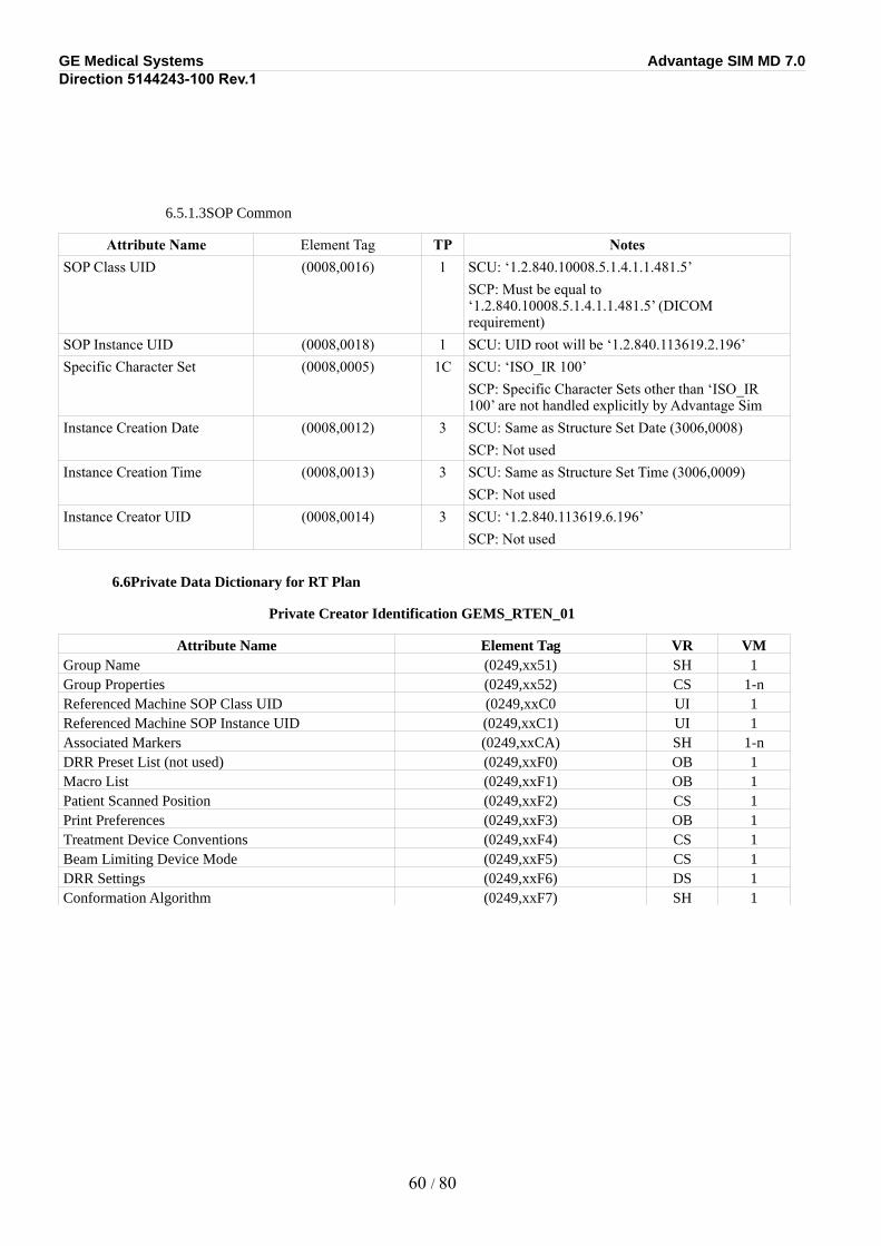
GE Medical Systems Advantage SIM MD 7.0Direction 5144243-100 Rev.1
6.5.1.3SOP Common
Attribute Name Element Tag TP NotesSOP Class UID (0008,0016) 1 SCU: ‘1.2.840.10008.5.1.4.1.1.481.5’
SCP: Must be equal to ‘1.2.840.10008.5.1.4.1.1.481.5’ (DICOM requirement)
SOP Instance UID (0008,0018) 1 SCU: UID root will be ‘1.2.840.113619.2.196’Specific Character Set (0008,0005) 1C SCU: ‘ISO_IR 100’
SCP: Specific Character Sets other than ‘ISO_IR 100’ are not handled explicitly by Advantage Sim
Instance Creation Date (0008,0012) 3 SCU: Same as Structure Set Date (3006,0008)SCP: Not used
Instance Creation Time (0008,0013) 3 SCU: Same as Structure Set Time (3006,0009)SCP: Not used
Instance Creator UID (0008,0014) 3 SCU: ‘1.2.840.113619.6.196’SCP: Not used
6.6Private Data Dictionary for RT Plan
Private Creator Identification GEMS_RTEN_01
Attribute Name Element Tag VR VMGroup Name (0249,xx51) SH 1Group Properties (0249,xx52) CS 1-nReferenced Machine SOP Class UID (0249,xxC0 UI 1Referenced Machine SOP Instance UID (0249,xxC1) UI 1Associated Markers (0249,xxCA) SH 1-nDRR Preset List (not used) (0249,xxF0) OB 1Macro List (0249,xxF1) OB 1Patient Scanned Position (0249,xxF2) CS 1Print Preferences (0249,xxF3) OB 1Treatment Device Conventions (0249,xxF4) CS 1Beam Limiting Device Mode (0249,xxF5) CS 1DRR Settings (0249,xxF6) DS 1Conformation Algorithm (0249,xxF7) SH 1
60 / 80
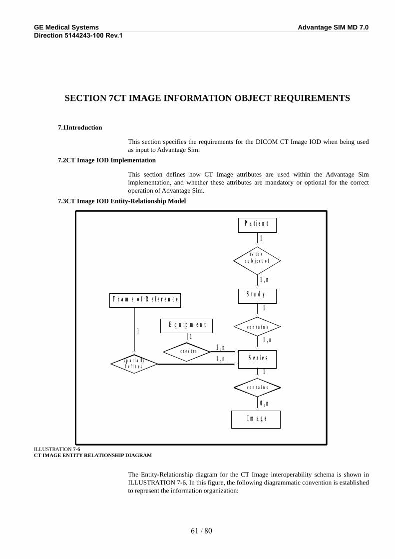
GE Medical Systems Advantage SIM MD 7.0Direction 5144243-100 Rev.1
SECTION 7CT IMAGE INFORMATION OBJECT REQUIREMENTS
7.1Introduction
This section specifies the requirements for the DICOM CT Image IOD when being used as input to Advantage Sim.
7.2CT Image IOD Implementation
This section defines how CT Image attributes are used within the Advantage Sim implementation, and whether these attributes are mandatory or optional for the correct operation of Advantage Sim.
7.3CT Image IOD Entity-Relationship Model
ILLUSTRATION 7-6CT IMAGE ENTITY RELATIONSHIP DIAGRAM
The Entity-Relationship diagram for the CT Image interoperability schema is shown in ILLUSTRATION 7-6. In this figure, the following diagrammatic convention is established to represent the information organization:
61 / 80
P a t i e n t
i s t h e s u b j e c t o f
S t u d y
c o n t a i n s
S e r i e s
c o n t a i n s
I m a g e
c r e a t e s
E q u i p m e n t
1
1
1
1 , n
0 , n
1 , n
1 , n
s p a t i a l l y
1 1
d e f i n e s
F r a m e o f R e f e r e n c e
1 , n
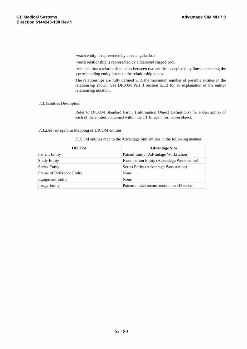
GE Medical Systems Advantage SIM MD 7.0Direction 5144243-100 Rev.1
•each entity is represented by a rectangular box
•each relationship is represented by a diamond shaped box.
•the fact that a relationship exists between two entities is depicted by lines connecting the corresponding entity boxes to the relationship boxes.
The relationships are fully defined with the maximum number of possible entities in the relationship shown. See DICOM Part 3 Section 5.1.2 for an explanation of the entity-relationship notation.
7.3.1Entities Description
Refer to DICOM Standard Part 3 (Information Object Definitions) for a description of each of the entities contained within the CT Image information object.
7.3.2Advantage Sim Mapping of DICOM entities
DICOM entities map to the Advantage Sim entities in the following manner:
DICOM Advantage SimPatient Entity Patient Entity (Advantage Workstation)Study Entity Examination Entity (Advantage Workstation)Series Entity Series Entity (Advantage Workstation)Frame of Reference Entity NoneEquipment Entity NoneImage Entity Patient model reconstruction on 3D server
62 / 80
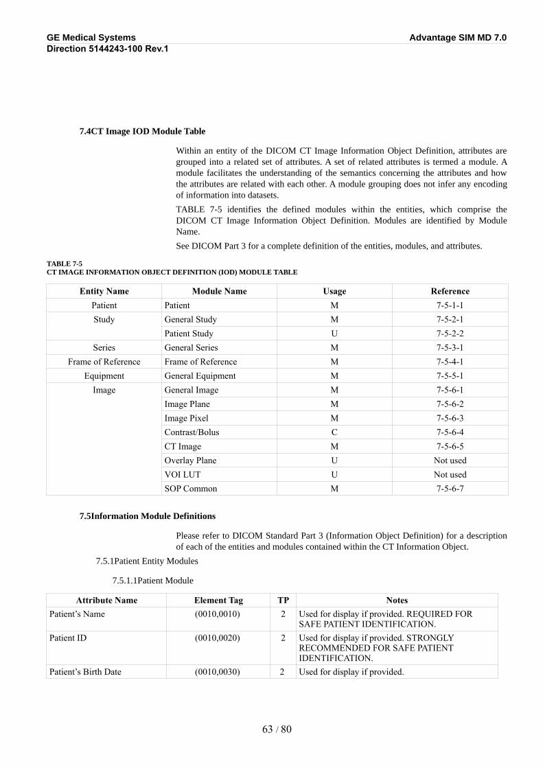
GE Medical Systems Advantage SIM MD 7.0Direction 5144243-100 Rev.1
7.4CT Image IOD Module Table
Within an entity of the DICOM CT Image Information Object Definition, attributes are grouped into a related set of attributes. A set of related attributes is termed a module. A module facilitates the understanding of the semantics concerning the attributes and how the attributes are related with each other. A module grouping does not infer any encoding of information into datasets.
TABLE 7-5 identifies the defined modules within the entities, which comprise the DICOM CT Image Information Object Definition. Modules are identified by Module Name.
See DICOM Part 3 for a complete definition of the entities, modules, and attributes.
TABLE 7-5CT IMAGE INFORMATION OBJECT DEFINITION (IOD) MODULE TABLE
Entity Name Module Name Usage ReferencePatient Patient M 7-5-1-1Study General Study M 7-5-2-1
Patient Study U 7-5-2-2Series General Series M 7-5-3-1
Frame of Reference Frame of Reference M 7-5-4-1Equipment General Equipment M 7-5-5-1
Image General Image M 7-5-6-1Image Plane M 7-5-6-2Image Pixel M 7-5-6-3Contrast/Bolus C 7-5-6-4CT Image M 7-5-6-5Overlay Plane U Not usedVOI LUT U Not usedSOP Common M 7-5-6-7
7.5Information Module Definitions
Please refer to DICOM Standard Part 3 (Information Object Definition) for a description of each of the entities and modules contained within the CT Information Object.
7.5.1Patient Entity Modules
7.5.1.1Patient Module
Attribute Name Element Tag TP NotesPatient’s Name (0010,0010) 2 Used for display if provided. REQUIRED FOR
SAFE PATIENT IDENTIFICATION.Patient ID (0010,0020) 2 Used for display if provided. STRONGLY
RECOMMENDED FOR SAFE PATIENT IDENTIFICATION.
Patient’s Birth Date (0010,0030) 2 Used for display if provided.
63 / 80
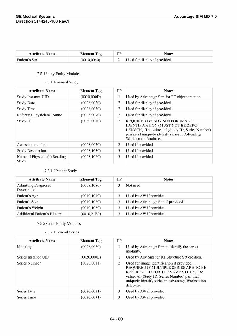
GE Medical Systems Advantage SIM MD 7.0Direction 5144243-100 Rev.1
Attribute Name Element Tag TP NotesPatient’s Sex (0010,0040) 2 Used for display if provided.
7.5.1Study Entity Modules
7.5.1.1General Study
Attribute Name Element Tag TP NotesStudy Instance UID (0020,000D) 1 Used by Advantage Sim for RT object creation.Study Date (0008,0020) 2 Used for display if provided.Study Time (0008,0030) 2 Used for display if provided.Referring Physicians’ Name (0008,0090) 2 Used for display if provided.Study ID (0020,0010) 2 REQUIRED BY ADV SIM FOR IMAGE
IDENTIFICATION (MUST NOT BE ZERO-LENGTH). The values of (Study ID, Series Number) pair must uniquely identify series in Advantage Workstation database.
Accession number (0008,0050) 2 Used if provided.Study Description (0008,1030) 3 Used if provided.Name of Physician(s) Reading Study
(0008,1060) 3 Used if provided.
7.5.1.2Patient Study
Attribute Name Element Tag TP NotesAdmitting Diagnoses Description
(0008,1080) 3 Not used.
Patient’s Age (0010,1010) 3 Used by AW if provided.Patient's Size (0010,1020) 3 Used by Advantage Sim if provided.Patient’s Weight (0010,1030) 3 Used by AW if provided.Additional Patient’s History (0010,21B0) 3 Used by AW if provided.
7.5.2Series Entity Modules
7.5.2.1General Series
Attribute Name Element Tag TP NotesModality (0008,0060) 1 Used by Advantage Sim to identify the series
modality.Series Instance UID (0020,000E) 1 Used by Adv Sim for RT Structure Set creation.Series Number (0020,0011) 2 Used for image identification if provided.
REQUIRED IF MULTIPLE SERIES ARE TO BE REFERENCED FOR THE SAME STUDY. The values of (Study ID, Series Number) pair must uniquely identify series in Advantage Workstation database.
Series Date (0020,0021) 3 Used by AW if provided.Series Time (0020,0031) 3 Used by AW if provided.
64 / 80
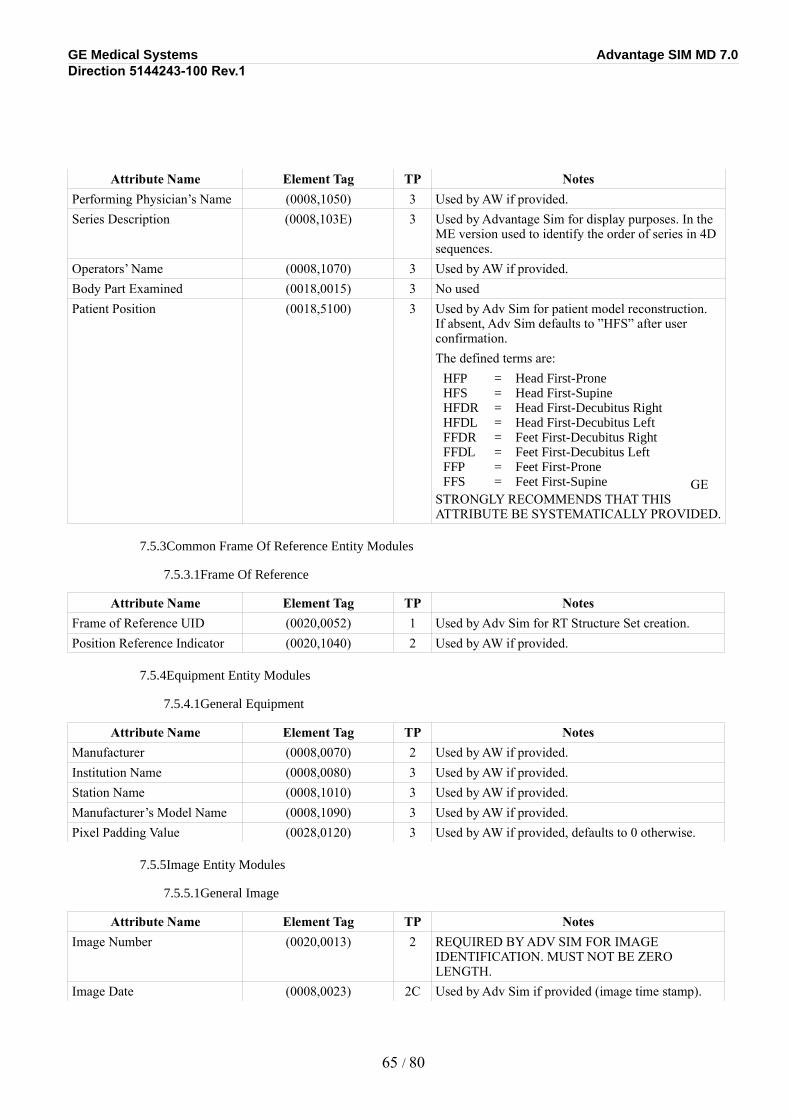
GE Medical Systems Advantage SIM MD 7.0Direction 5144243-100 Rev.1
Attribute Name Element Tag TP NotesPerforming Physician’s Name (0008,1050) 3 Used by AW if provided.Series Description (0008,103E) 3 Used by Advantage Sim for display purposes. In the
ME version used to identify the order of series in 4D sequences.
Operators’ Name (0008,1070) 3 Used by AW if provided.Body Part Examined (0018,0015) 3 No usedPatient Position (0018,5100) 3 Used by Adv Sim for patient model reconstruction.
If absent, Adv Sim defaults to ”HFS” after user confirmation.The defined terms are:
HFP = Head First-ProneHFS = Head First-SupineHFDR = Head First-Decubitus RightHFDL = Head First-Decubitus LeftFFDR = Feet First-Decubitus RightFFDL = Feet First-Decubitus LeftFFP = Feet First-ProneFFS = Feet First-Supine GE
STRONGLY RECOMMENDS THAT THIS ATTRIBUTE BE SYSTEMATICALLY PROVIDED.
7.5.3Common Frame Of Reference Entity Modules
7.5.3.1Frame Of Reference
Attribute Name Element Tag TP NotesFrame of Reference UID (0020,0052) 1 Used by Adv Sim for RT Structure Set creation.Position Reference Indicator (0020,1040) 2 Used by AW if provided.
7.5.4Equipment Entity Modules
7.5.4.1General Equipment
Attribute Name Element Tag TP NotesManufacturer (0008,0070) 2 Used by AW if provided.Institution Name (0008,0080) 3 Used by AW if provided.Station Name (0008,1010) 3 Used by AW if provided.Manufacturer’s Model Name (0008,1090) 3 Used by AW if provided.Pixel Padding Value (0028,0120) 3 Used by AW if provided, defaults to 0 otherwise.
7.5.5Image Entity Modules
7.5.5.1General Image
Attribute Name Element Tag TP NotesImage Number (0020,0013) 2 REQUIRED BY ADV SIM FOR IMAGE
IDENTIFICATION. MUST NOT BE ZERO LENGTH.
Image Date (0008,0023) 2C Used by Adv Sim if provided (image time stamp).
65 / 80
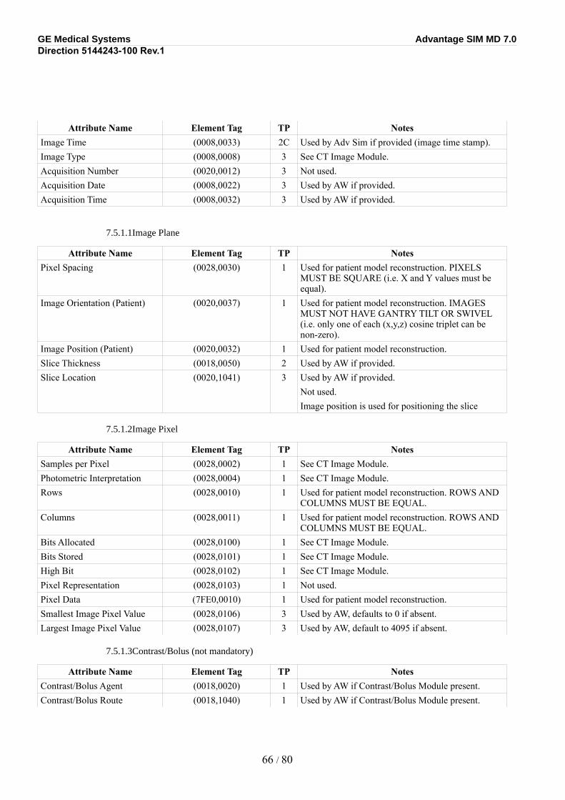
GE Medical Systems Advantage SIM MD 7.0Direction 5144243-100 Rev.1
Attribute Name Element Tag TP NotesImage Time (0008,0033) 2C Used by Adv Sim if provided (image time stamp).Image Type (0008,0008) 3 See CT Image Module.Acquisition Number (0020,0012) 3 Not used.Acquisition Date (0008,0022) 3 Used by AW if provided.Acquisition Time (0008,0032) 3 Used by AW if provided.
7.5.1.1Image Plane
Attribute Name Element Tag TP NotesPixel Spacing (0028,0030) 1 Used for patient model reconstruction. PIXELS
MUST BE SQUARE (i.e. X and Y values must be equal).
Image Orientation (Patient) (0020,0037) 1 Used for patient model reconstruction. IMAGES MUST NOT HAVE GANTRY TILT OR SWIVEL (i.e. only one of each (x,y,z) cosine triplet can be non-zero).
Image Position (Patient) (0020,0032) 1 Used for patient model reconstruction.Slice Thickness (0018,0050) 2 Used by AW if provided.Slice Location (0020,1041) 3 Used by AW if provided.
Not used. Image position is used for positioning the slice
7.5.1.2Image Pixel
Attribute Name Element Tag TP NotesSamples per Pixel (0028,0002) 1 See CT Image Module.Photometric Interpretation (0028,0004) 1 See CT Image Module.Rows (0028,0010) 1 Used for patient model reconstruction. ROWS AND
COLUMNS MUST BE EQUAL.Columns (0028,0011) 1 Used for patient model reconstruction. ROWS AND
COLUMNS MUST BE EQUAL.Bits Allocated (0028,0100) 1 See CT Image Module.Bits Stored (0028,0101) 1 See CT Image Module.High Bit (0028,0102) 1 See CT Image Module.Pixel Representation (0028,0103) 1 Not used.Pixel Data (7FE0,0010) 1 Used for patient model reconstruction.Smallest Image Pixel Value (0028,0106) 3 Used by AW, defaults to 0 if absent.Largest Image Pixel Value (0028,0107) 3 Used by AW, default to 4095 if absent.
7.5.1.3Contrast/Bolus (not mandatory)
Attribute Name Element Tag TP NotesContrast/Bolus Agent (0018,0020) 1 Used by AW if Contrast/Bolus Module present.Contrast/Bolus Route (0018,1040) 1 Used by AW if Contrast/Bolus Module present.
66 / 80
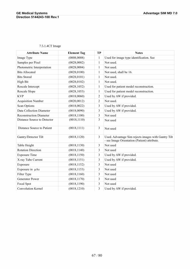
GE Medical Systems Advantage SIM MD 7.0Direction 5144243-100 Rev.1
7.5.1.4CT Image
Attribute Name Element Tag TP NotesImage Type (0008,0008) 1 Used for image type identification. See Samples per Pixel (0028,0002) 1 Not used.Photometric Interpretation (0028,0004) 1 Not used.Bits Allocated (0028,0100) 1 Not used, shall be 16.Bits Stored (0028,0101) 1 Not used.High Bit (0028,0102) 1 Not used.Rescale Intercept (0028,1052) 1 Used for patient model reconstruction.Rescale Slope (0028,1053) 1 Used for patient model reconstruction.KVP (0018,0060) 2 Used by AW if provided.Acquisition Number (0020,0012) 2 Not used.Scan Options (0018,0022) 3 Used by AW if provided.Data Collection Diameter (0018,0090) 3 Used by AW if provided.Reconstruction Diameter (0018,1100) 3 Not usedDistance Source to Detector (0018,1110) 3 Not used
Distance Source to Patient (0018,1111) 3 Not used
Gantry/Detector Tilt (0018,1120) 3 Used. Advantage Sim rejects images with Gantry Tilt - see Image Orientation (Patient) attribute.
Table Height (0018,1130) 3 Not usedRotation Direction (0018,1140) 3 Not usedExposure Time (0018,1150) 3 Used by AW if provided.X-ray Tube Current (0018,1151) 3 Used by AW if provided.Exposure (0018,1152) 3 Not usedExposure in μAs (0018,1153) 3 Not usedFilter Type (0018,1160) 3 Not usedGenerator Power (0018,1170) 3 Not usedFocal Spot (0018,1190) 3 Not usedConvolution Kernel (0018,1210) 3 Used by AW if provided.
67 / 80
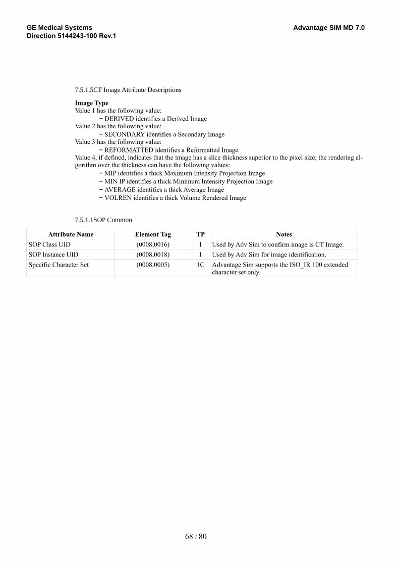
GE Medical Systems Advantage SIM MD 7.0Direction 5144243-100 Rev.1
7.5.1.5CT Image Attribute Descriptions
Image TypeValue 1 has the following value:
− DERIVED identifies a Derived ImageValue 2 has the following value:
− SECONDARY identifies a Secondary ImageValue 3 has the following value:
− REFORMATTED identifies a Reformatted ImageValue 4, if defined, indicates that the image has a slice thickness superior to the pixel size; the rendering al-gorithm over the thickness can have the following values:
− MIP identifies a thick Maximum Intensity Projection Image− MIN IP identifies a thick Minimum Intensity Projection Image− AVERAGE identifies a thick Average Image− VOLREN identifies a thick Volume Rendered Image
7.5.1.1SOP Common
Attribute Name Element Tag TP NotesSOP Class UID (0008,0016) 1 Used by Adv Sim to confirm image is CT Image.SOP Instance UID (0008,0018) 1 Used by Adv Sim for image identification.Specific Character Set (0008,0005) 1C Advantage Sim supports the ISO_IR 100 extended
character set only.
68 / 80
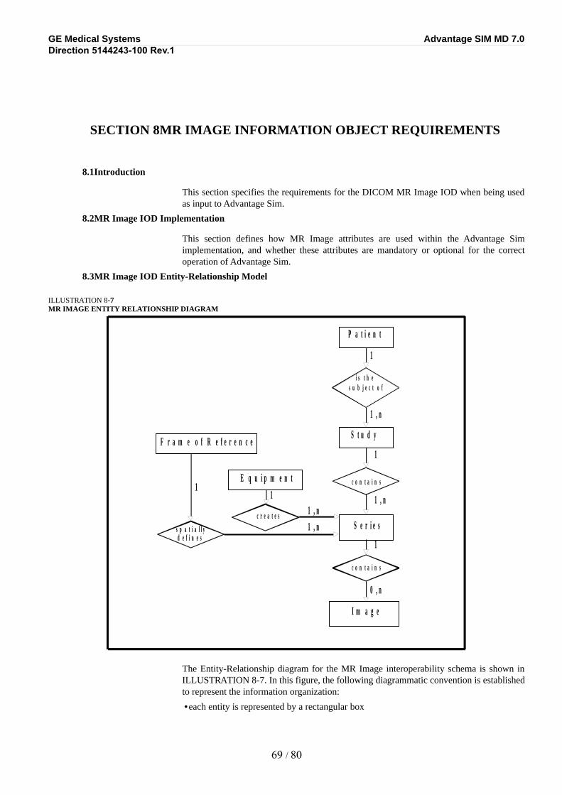
GE Medical Systems Advantage SIM MD 7.0Direction 5144243-100 Rev.1
SECTION 8MR IMAGE INFORMATION OBJECT REQUIREMENTS
8.1Introduction
This section specifies the requirements for the DICOM MR Image IOD when being used as input to Advantage Sim.
8.2MR Image IOD Implementation
This section defines how MR Image attributes are used within the Advantage Sim implementation, and whether these attributes are mandatory or optional for the correct operation of Advantage Sim.
8.3MR Image IOD Entity-Relationship Model
ILLUSTRATION 8-7MR IMAGE ENTITY RELATIONSHIP DIAGRAM
The Entity-Relationship diagram for the MR Image interoperability schema is shown in ILLUSTRATION 8-7. In this figure, the following diagrammatic convention is established to represent the information organization:
•each entity is represented by a rectangular box
69 / 80
P a t i e n t
i s t h e s u b j e c t o f
S t u d y
c o n t a i n s
S e r i e s
c o n t a i n s
I m a g e
c r e a t e s
E q u i p m e n t
1
1
1
1 , n
0 , n
1 , n
1 , n
s p a t i a l l y
1 1
d e f i n e s
F r a m e o f R e f e r e n c e
1 , n
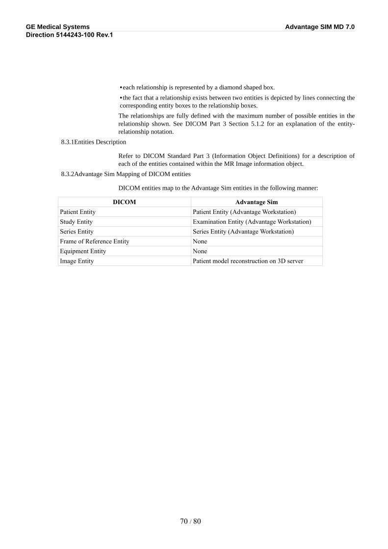
GE Medical Systems Advantage SIM MD 7.0Direction 5144243-100 Rev.1
•each relationship is represented by a diamond shaped box.
•the fact that a relationship exists between two entities is depicted by lines connecting the corresponding entity boxes to the relationship boxes.
The relationships are fully defined with the maximum number of possible entities in the relationship shown. See DICOM Part 3 Section 5.1.2 for an explanation of the entity-relationship notation.
8.3.1Entities Description
Refer to DICOM Standard Part 3 (Information Object Definitions) for a description of each of the entities contained within the MR Image information object.
8.3.2Advantage Sim Mapping of DICOM entities
DICOM entities map to the Advantage Sim entities in the following manner:
DICOM Advantage SimPatient Entity Patient Entity (Advantage Workstation)Study Entity Examination Entity (Advantage Workstation)Series Entity Series Entity (Advantage Workstation)Frame of Reference Entity NoneEquipment Entity NoneImage Entity Patient model reconstruction on 3D server
70 / 80
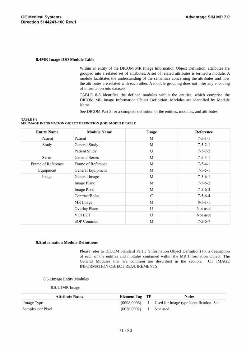
GE Medical Systems Advantage SIM MD 7.0Direction 5144243-100 Rev.1
8.4MR Image IOD Module Table
Within an entity of the DICOM MR Image Information Object Definition, attributes are grouped into a related set of attributes. A set of related attributes is termed a module. A module facilitates the understanding of the semantics concerning the attributes and how the attributes are related with each other. A module grouping does not infer any encoding of information into datasets.
TABLE 8-6 identifies the defined modules within the entities, which comprise the DICOM MR Image Information Object Definition. Modules are identified by Module Name.
See DICOM Part 3 for a complete definition of the entities, modules, and attributes.
TABLE 8-6MR IMAGE INFORMATION OBJECT DEFINITION (IOD) MODULE TABLE
Entity Name Module Name Usage ReferencePatient Patient M 7-5-1-1Study General Study M 7-5-2-1
Patient Study U 7-5-2-2Series General Series M 7-5-3-1
Frame of Reference Frame of Reference M 7-5-4-1Equipment General Equipment M 7-5-5-1
Image General Image M 7-5-6-1Image Plane M 7-5-6-2Image Pixel M 7-5-6-3Contrast/Bolus C 7-5-6-4MR Image M 8-5-1-1Overlay Plane U Not usedVOI LUT U Not usedSOP Common M 7-5-6-7
8.5Information Module Definitions
Please refer to DICOM Standard Part 3 (Information Object Definition) for a description of each of the entities and modules contained within the MR Information Object. The General Modules that are common are described in the section: CT IMAGE INFORMATION OBJECT REQUIREMENTS.
8.5.1Image Entity Modules
8.5.1.1MR Image
Attribute Name Element Tag TP Notes Image Type (0008,0008) 1 Used for image type identification. See
Samples per Pixel (0028,0002) 1 Not used.
71 / 80
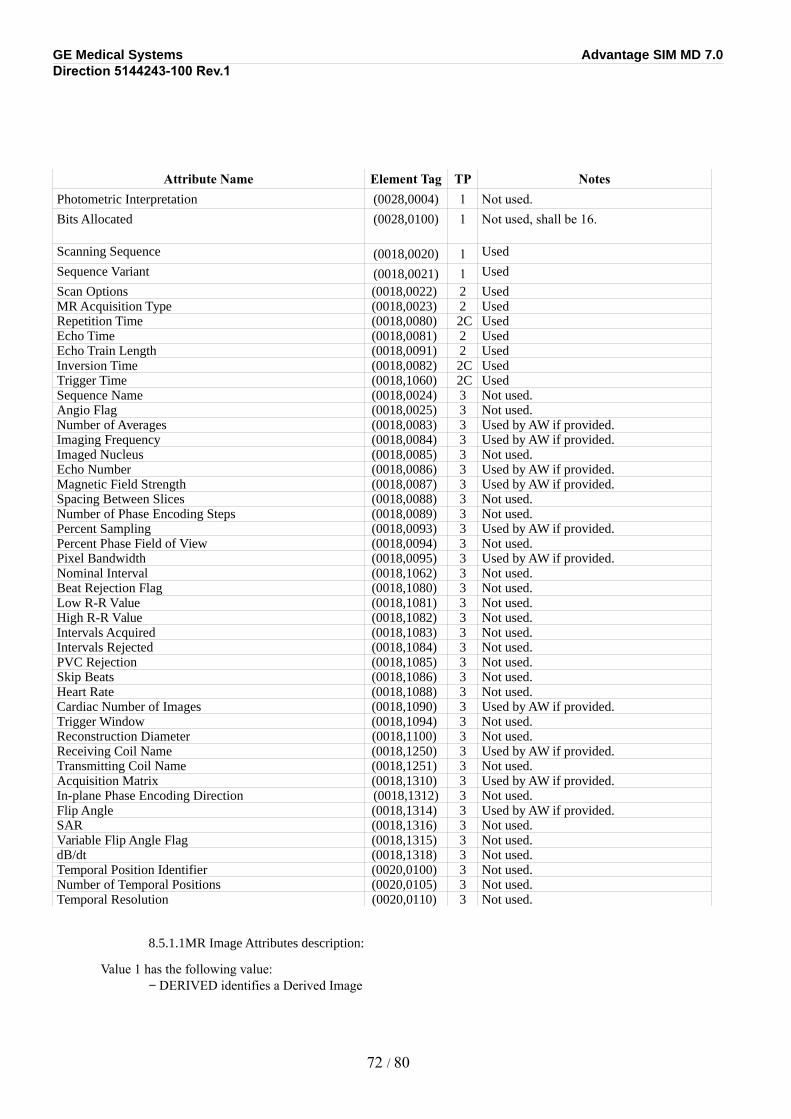
GE Medical Systems Advantage SIM MD 7.0Direction 5144243-100 Rev.1
Attribute Name Element Tag TP NotesPhotometric Interpretation (0028,0004) 1 Not used.Bits Allocated (0028,0100) 1 Not used, shall be 16.
Scanning Sequence (0018,0020) 1 Used
Sequence Variant (0018,0021) 1 Used
Scan Options (0018,0022) 2 UsedMR Acquisition Type (0018,0023) 2 UsedRepetition Time (0018,0080) 2C UsedEcho Time (0018,0081) 2 UsedEcho Train Length (0018,0091) 2 UsedInversion Time (0018,0082) 2C UsedTrigger Time (0018,1060) 2C UsedSequence Name (0018,0024) 3 Not used.Angio Flag (0018,0025) 3 Not used.Number of Averages (0018,0083) 3 Used by AW if provided.Imaging Frequency (0018,0084) 3 Used by AW if provided.Imaged Nucleus (0018,0085) 3 Not used.Echo Number (0018,0086) 3 Used by AW if provided.Magnetic Field Strength (0018,0087) 3 Used by AW if provided.Spacing Between Slices (0018,0088) 3 Not used.Number of Phase Encoding Steps (0018,0089) 3 Not used.Percent Sampling (0018,0093) 3 Used by AW if provided.Percent Phase Field of View (0018,0094) 3 Not used.Pixel Bandwidth (0018,0095) 3 Used by AW if provided.Nominal Interval (0018,1062) 3 Not used.Beat Rejection Flag (0018,1080) 3 Not used.Low R-R Value (0018,1081) 3 Not used.High R-R Value (0018,1082) 3 Not used.Intervals Acquired (0018,1083) 3 Not used.Intervals Rejected (0018,1084) 3 Not used.PVC Rejection (0018,1085) 3 Not used.Skip Beats (0018,1086) 3 Not used.Heart Rate (0018,1088) 3 Not used.Cardiac Number of Images (0018,1090) 3 Used by AW if provided.Trigger Window (0018,1094) 3 Not used.Reconstruction Diameter (0018,1100) 3 Not used.Receiving Coil Name (0018,1250) 3 Used by AW if provided.Transmitting Coil Name (0018,1251) 3 Not used.Acquisition Matrix (0018,1310) 3 Used by AW if provided.In-plane Phase Encoding Direction (0018,1312) 3 Not used.Flip Angle (0018,1314) 3 Used by AW if provided.SAR (0018,1316) 3 Not used.Variable Flip Angle Flag (0018,1315) 3 Not used.dB/dt (0018,1318) 3 Not used.Temporal Position Identifier (0020,0100) 3 Not used.Number of Temporal Positions (0020,0105) 3 Not used.Temporal Resolution (0020,0110) 3 Not used.
8.5.1.1MR Image Attributes description:
Value 1 has the following value:− DERIVED identifies a Derived Image
72 / 80
GE Medical Systems Advantage SIM MD 7.0Direction 5144243-100 Rev.1
Value 2 has the following value:− SECONDARY identifies a Secondary Image
Value 3 has the following value:− PJN identifies a MIP reconstructed image− REFORMATTED identifies a Multi Planar Reformatted Image
PJN is the same than PROJECTION IMAGE, and REFORMATTED is the same than MPR, but it kept in order to ensure the image can be pushed on old GE MR system.Value 4, if defined, indicates that the image has a slice thickness superior to the pixel size; the rendering algorithm over the thickness can have the following values:
− MIP identifies a thick Maximum Intensity Projection Image− MIN IP identifies a thick Minimum Intensity Projection Image− AVERAGE identifies a thick Average Image− VOLREN identifies a thick Volume Rendered Image
73 / 80
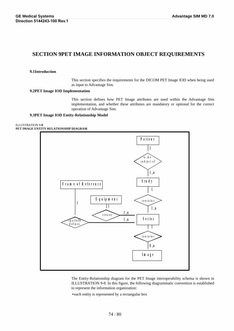
GE Medical Systems Advantage SIM MD 7.0Direction 5144243-100 Rev.1
SECTION 9PET IMAGE INFORMATION OBJECT REQUIREMENTS
9.1Introduction
This section specifies the requirements for the DICOM PET Image IOD when being used as input to Advantage Sim.
9.2PET Image IOD Implementation
This section defines how PET Image attributes are used within the Advantage Sim implementation, and whether these attributes are mandatory or optional for the correct operation of Advantage Sim.
9.3PET Image IOD Entity-Relationship Model
ILLUSTRATION 9-8PET IMAGE ENTITY RELATIONSHIP DIAGRAM
The Entity-Relationship diagram for the PET Image interoperability schema is shown in ILLUSTRATION 9-8. In this figure, the following diagrammatic convention is established to represent the information organization:
•each entity is represented by a rectangular box
74 / 80
P a t i e n t
i s t h e s u b j e c t o f
S t u d y
c o n t a i n s
S e r i e s
c o n t a i n s
I m a g e
c r e a t e s
E q u i p m e n t
1
1
1
1 , n
0 , n
1 , n
1 , n
s p a t i a l l y
1 1
d e f i n e s
F r a m e o f R e f e r e n c e
1 , n
GE Medical Systems Advantage SIM MD 7.0Direction 5144243-100 Rev.1
•each relationship is represented by a diamond shaped box.
•the fact that a relationship exists between two entities is depicted by lines connecting the corresponding entity boxes to the relationship boxes.
The relationships are fully defined with the maximum number of possible entities in the relationship shown. See DICOM Part 3 Section 5.1.2 for an explanation of the entity-relationship notation.
9.3.1Entities Description
Refer to DICOM Standard Part 3 (Information Object Definitions) for a description of each of the entities contained within the PET Image information object.
9.3.2Advantage Sim Mapping of DICOM entities
DICOM entities map to the Advantage Sim entities in the following manner:
DICOM Advantage SimPatient Entity Patient Entity (Advantage Workstation)Study Entity Examination Entity (Advantage Workstation)Series Entity Series Entity (Advantage Workstation)Frame of Reference Entity NoneEquipment Entity NoneImage Entity Patient model reconstruction on 3D server
75 / 80
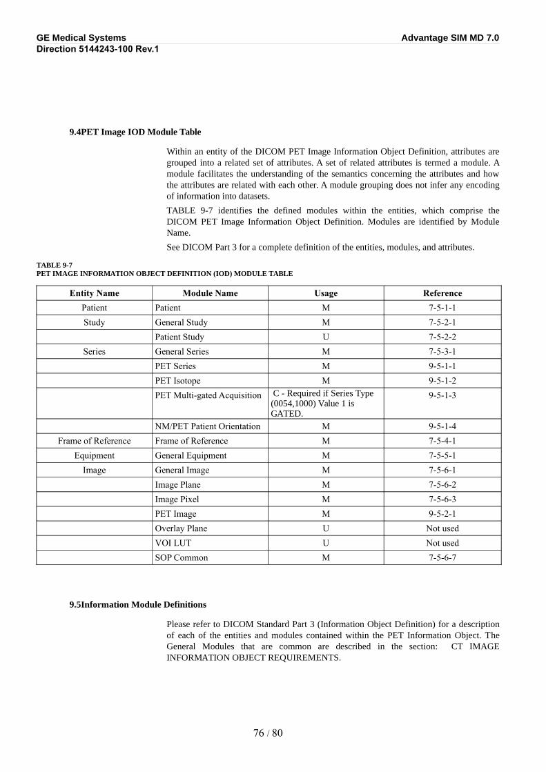
GE Medical Systems Advantage SIM MD 7.0Direction 5144243-100 Rev.1
9.4PET Image IOD Module Table
Within an entity of the DICOM PET Image Information Object Definition, attributes are grouped into a related set of attributes. A set of related attributes is termed a module. A module facilitates the understanding of the semantics concerning the attributes and how the attributes are related with each other. A module grouping does not infer any encoding of information into datasets.
TABLE 9-7 identifies the defined modules within the entities, which comprise the DICOM PET Image Information Object Definition. Modules are identified by Module Name.
See DICOM Part 3 for a complete definition of the entities, modules, and attributes.
TABLE 9-7PET IMAGE INFORMATION OBJECT DEFINITION (IOD) MODULE TABLE
Entity Name Module Name Usage ReferencePatient Patient M 7-5-1-1Study General Study M 7-5-2-1
Patient Study U 7-5-2-2Series General Series M 7-5-3-1
PET Series M 9-5-1-1PET Isotope M 9-5-1-2PET Multi-gated Acquisition C - Required if Series Type
(0054,1000) Value 1 is GATED.
9-5-1-3
NM/PET Patient Orientation M 9-5-1-4Frame of Reference Frame of Reference M 7-5-4-1
Equipment General Equipment M 7-5-5-1Image General Image M 7-5-6-1
Image Plane M 7-5-6-2Image Pixel M 7-5-6-3PET Image M 9-5-2-1Overlay Plane U Not usedVOI LUT U Not usedSOP Common M 7-5-6-7
9.5Information Module Definitions
Please refer to DICOM Standard Part 3 (Information Object Definition) for a description of each of the entities and modules contained within the PET Information Object. The General Modules that are common are described in the section: CT IMAGE INFORMATION OBJECT REQUIREMENTS.
76 / 80
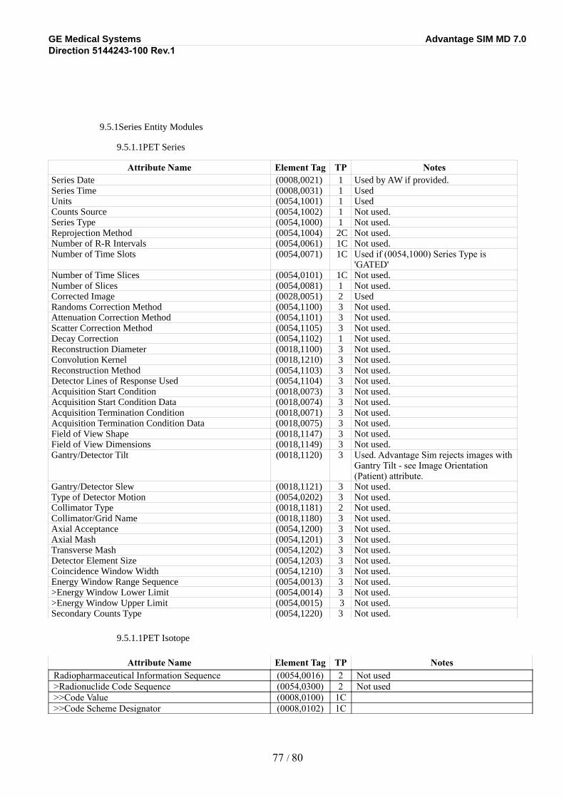
GE Medical Systems Advantage SIM MD 7.0Direction 5144243-100 Rev.1
9.5.1Series Entity Modules
9.5.1.1PET Series
Attribute Name Element Tag TP NotesSeries Date (0008,0021) 1 Used by AW if provided. Series Time (0008,0031) 1 UsedUnits (0054,1001) 1 UsedCounts Source (0054,1002) 1 Not used.Series Type (0054,1000) 1 Not used.Reprojection Method (0054,1004) 2C Not used.Number of R-R Intervals (0054,0061) 1C Not used.Number of Time Slots (0054,0071) 1C Used if (0054,1000) Series Type is
'GATED'Number of Time Slices (0054,0101) 1C Not used.Number of Slices (0054,0081) 1 Not used.Corrected Image (0028,0051) 2 UsedRandoms Correction Method (0054,1100) 3 Not used.Attenuation Correction Method (0054,1101) 3 Not used.Scatter Correction Method (0054,1105) 3 Not used.Decay Correction (0054,1102) 1 Not used.Reconstruction Diameter (0018,1100) 3 Not used.Convolution Kernel (0018,1210) 3 Not used.Reconstruction Method (0054,1103) 3 Not used.Detector Lines of Response Used (0054,1104) 3 Not used.Acquisition Start Condition (0018,0073) 3 Not used.Acquisition Start Condition Data (0018,0074) 3 Not used.Acquisition Termination Condition (0018,0071) 3 Not used.Acquisition Termination Condition Data (0018,0075) 3 Not used.Field of View Shape (0018,1147) 3 Not used.Field of View Dimensions (0018,1149) 3 Not used.Gantry/Detector Tilt (0018,1120) 3 Used. Advantage Sim rejects images with
Gantry Tilt - see Image Orientation (Patient) attribute.
Gantry/Detector Slew (0018,1121) 3 Not used.Type of Detector Motion (0054,0202) 3 Not used.Collimator Type (0018,1181) 2 Not used.Collimator/Grid Name (0018,1180) 3 Not used.Axial Acceptance (0054,1200) 3 Not used.Axial Mash (0054,1201) 3 Not used.Transverse Mash (0054,1202) 3 Not used.Detector Element Size (0054,1203) 3 Not used.Coincidence Window Width (0054,1210) 3 Not used.Energy Window Range Sequence (0054,0013) 3 Not used.>Energy Window Lower Limit (0054,0014) 3 Not used.>Energy Window Upper Limit (0054,0015) 3 Not used.Secondary Counts Type (0054,1220) 3 Not used.
9.5.1.1PET Isotope
Attribute Name Element Tag TP NotesRadiopharmaceutical Information Sequence (0054,0016) 2 Not used>Radionuclide Code Sequence (0054,0300) 2 Not used>>Code Value (0008,0100) 1C>>Code Scheme Designator (0008,0102) 1C
77 / 80
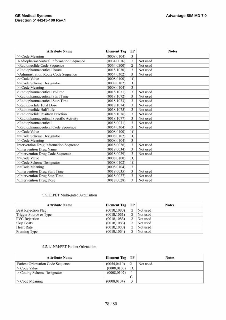
GE Medical Systems Advantage SIM MD 7.0Direction 5144243-100 Rev.1
Attribute Name Element Tag TP Notes>>Code Meaning (0008,0104) 3 Radiopharmaceutical Information Sequence (0054,0016) 2 Not used>Radionuclide Code Sequence (0054,0300) 2 Not used>Radiopharmaceutical Route (0018,1070) 3 Not used>Administration Route Code Sequence (0054,0302) 3 Not used>>Code Value (0008,0100) 1C>>Code Scheme Designator (0008,0102) 1C>>Code Meaning (0008,0104) 3>Radiopharmaceutical Volume (0018,1071) 3 Not used>Radiopharmaceutical Start Time (0018,1072) 3 Not used>Radiopharmaceutical Stop Time (0018,1073) 3 Not used>Radionuclide Total Dose (0018,1074) 3 Not used>Radionuclide Half Life (0018,1075) 3 Not used>Radionuclide Positron Fraction (0018,1076) 3 Not used>Radiopharmaceutical Specific Activity (0018,1077) 3 Not used>Radiopharmaceutical (0018,0031) 3 Not used>Radiopharmaceutical Code Sequence (0054,0304) 3 Not used>>Code Value (0008,0100) 1C>>Code Scheme Designator (0008,0102) 1C>>Code Meaning (0008,0104) 3Intervention Drug Information Sequence (0018,0026) 3 Not used>Intervention Drug Name (0018,0034) 3 Not used>Intervention Drug Code Sequence (0018,0029) 3 Not used>>Code Value (0008,0100) 1C>>Code Scheme Designator (0008,0102) 1C>>Code Meaning (0008,0104) 3>Intervention Drug Start Time (0018,0035) 3 Not used>Intervention Drug Stop Time (0018,0027) 3 Not used>Intervention Drug Dose (0018,0028) 3 Not used
9.5.1.1PET Multi-gated Acquisition
Attribute Name Element Tag TP NotesBeat Rejection Flag (0018,1080) 2 Not usedTrigger Source or Type (0018,1061) 3 Not usedPVC Rejection (0018,1085) 3 Not usedSkip Beats (0018,1086) 3 Not usedHeart Rate (0018,1088) 3 Not usedFraming Type (0018,1064) 3 Not used
9.5.1.1NM/PET Patient Orientation
Attribute Name Element Tag TP NotesPatient Orientation Code Sequence (0054,0410) 2 Not used.> Code Value (0008,0100) 1C> Coding Scheme Designator (0008,0102) 1
C> Code Meaning (0008,0104) 3
78 / 80
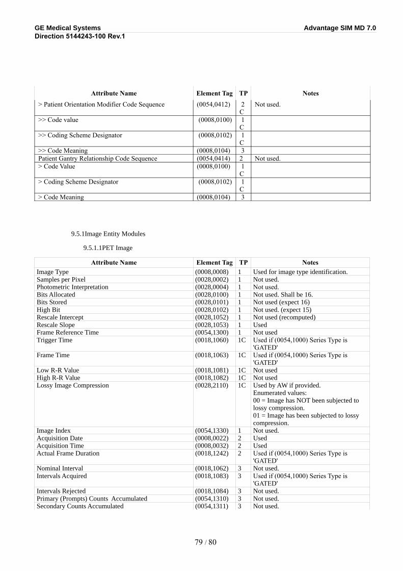
GE Medical Systems Advantage SIM MD 7.0Direction 5144243-100 Rev.1
Attribute Name Element Tag TP Notes> Patient Orientation Modifier Code Sequence (0054,0412) 2
CNot used.
>> Code value (0008,0100) 1C
>> Coding Scheme Designator (0008,0102) 1C
>> Code Meaning (0008,0104) 3Patient Gantry Relationship Code Sequence (0054,0414) 2 Not used.> Code Value (0008,0100) 1
C> Coding Scheme Designator (0008,0102) 1
C> Code Meaning (0008,0104) 3
9.5.1Image Entity Modules
9.5.1.1PET Image
Attribute Name Element Tag TP NotesImage Type (0008,0008) 1 Used for image type identification.Samples per Pixel (0028,0002) 1 Not used.Photometric Interpretation (0028,0004) 1 Not used.Bits Allocated (0028,0100) 1 Not used. Shall be 16.Bits Stored (0028,0101) 1 Not used (expect 16)High Bit (0028,0102) 1 Not used. (expect 15)Rescale Intercept (0028,1052) 1 Not used (recomputed)Rescale Slope (0028,1053) 1 UsedFrame Reference Time (0054,1300) 1 Not usedTrigger Time (0018,1060) 1C Used if (0054,1000) Series Type is
'GATED'Frame Time (0018,1063) 1C Used if (0054,1000) Series Type is
'GATED'Low R-R Value (0018,1081) 1C Not usedHigh R-R Value (0018,1082) 1C Not usedLossy Image Compression (0028,2110) 1C Used by AW if provided.
Enumerated values: 00 = Image has NOT been subjected to lossy compression. 01 = Image has been subjected to lossy compression.
Image Index (0054,1330) 1 Not used.Acquisition Date (0008,0022) 2 UsedAcquisition Time (0008,0032) 2 UsedActual Frame Duration (0018,1242) 2 Used if (0054,1000) Series Type is
'GATED'Nominal Interval (0018,1062) 3 Not used.Intervals Acquired (0018,1083) 3 Used if (0054,1000) Series Type is
'GATED'Intervals Rejected (0018,1084) 3 Not used.Primary (Prompts) Counts Accumulated (0054,1310) 3 Not used.Secondary Counts Accumulated (0054,1311) 3 Not used.
79 / 80
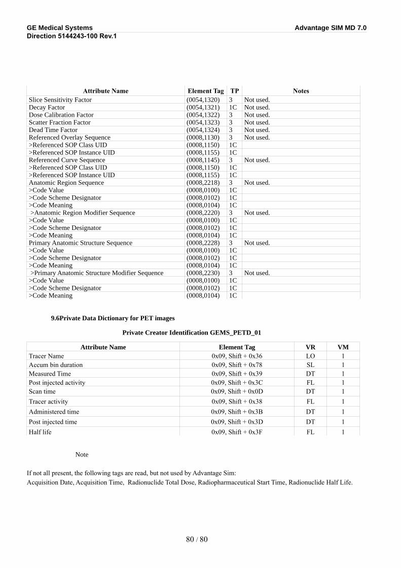
GE Medical Systems Advantage SIM MD 7.0Direction 5144243-100 Rev.1
Attribute Name Element Tag TP NotesSlice Sensitivity Factor (0054,1320) 3 Not used.Decay Factor (0054,1321) 1C Not used.Dose Calibration Factor (0054,1322) 3 Not used.Scatter Fraction Factor (0054,1323) 3 Not used.Dead Time Factor (0054,1324) 3 Not used.Referenced Overlay Sequence (0008,1130) 3 Not used.>Referenced SOP Class UID (0008,1150) 1C>Referenced SOP Instance UID (0008,1155) 1CReferenced Curve Sequence (0008,1145) 3 Not used.>Referenced SOP Class UID (0008,1150) 1C>Referenced SOP Instance UID (0008,1155) 1CAnatomic Region Sequence (0008,2218) 3 Not used.>Code Value (0008,0100) 1C>Code Scheme Designator (0008,0102) 1C>Code Meaning (0008,0104) 1C >Anatomic Region Modifier Sequence (0008,2220) 3 Not used.>Code Value (0008,0100) 1C>Code Scheme Designator (0008,0102) 1C>Code Meaning (0008,0104) 1CPrimary Anatomic Structure Sequence (0008,2228) 3 Not used.>Code Value (0008,0100) 1C>Code Scheme Designator (0008,0102) 1C>Code Meaning (0008,0104) 1C >Primary Anatomic Structure Modifier Sequence (0008,2230) 3 Not used.>Code Value (0008,0100) 1C>Code Scheme Designator (0008,0102) 1C>Code Meaning (0008,0104) 1C
9.6Private Data Dictionary for PET images
Private Creator Identification GEMS_PETD_01
Attribute Name Element Tag VR VMTracer Name 0x09, Shift + 0x36 LO 1Accum bin duration 0x09, Shift + 0x78 SL 1Measured Time 0x09, Shift + 0x39 DT 1Post injected activity 0x09, Shift + 0x3C FL 1Scan time 0x09, Shift + 0x0D DT 1Tracer activity 0x09, Shift + 0x38 FL 1Administered time 0x09, Shift + 0x3B DT 1Post injected time 0x09, Shift + 0x3D DT 1Half life 0x09, Shift + 0x3F FL 1
Note
If not all present, the following tags are read, but not used by Advantage Sim: Acquisition Date, Acquisition Time, Radionuclide Total Dose, Radiopharmaceutical Start Time, Radionuclide Half Life.
80 / 80
Related Documents