CHEROKEE HARD ROCK CASINO 4 04052018.0915 Concrete Forming and Accessories H17018.01 031000 - 1 SECTION 031000 CONCRETE FORMING AND ACCESSORIES PART 1 - GENERAL 1.1 WORK INCLUDED A. This section includes formwork for cast-in-place concrete, including water stops, and installation of embedded items. 1.2 RELATED WORK SPECIFIED ELSEWHERE A. Concrete Reinforcement - Section 03 20 00 B. Cast-In-Place Concrete - Section 03 30 00 C. Under-Slab Vapor Retarder – Section 07 26 00 1.3 QUALITY ASSURANCE A. Comply with the American Concrete Institute Standard, ACI 347-04, Recommended Practice for Concrete Formwork. 1.4 REFERENCE STANDARDS, latest editions of the following: A. American Society for Testing and Materials (ASTM) 1. ASTM D 226 Specification for Asphalt - Saturated Organic Felt used in Roofing and Waterproofing" 2. ASTM D 1751 Specification for Preformed Expansion Joint Filler for Concrete Paving and Structural Construction (Nonextruding and Resilient Bituminous Types) PART 2 - PRODUCTS 2.1 MATERIALS A. Forms for Exposed Finish Concrete: Plywood complying with Voluntary Product Standard PS 1-07 "B-B (Concrete Form) Plywood", Class I, Exterior Grade or better or metal, metal-framed plywood or other acceptable panel-type materials. Plywood shall be mill-oiled and edge- sealed, with each piece bearing legible inspection trademark. Furnish in largest practicable sizes to minimize number of joints. Provide form material with sufficient thickness to withstand pressure of newly placed concrete without bow or deflection. B. Forms for Unexposed Finish Concrete: Use plywood, lumber, metal or other acceptable material. Provide lumber dressed on at least 2 edges and one side for tight fit.

Welcome message from author
This document is posted to help you gain knowledge. Please leave a comment to let me know what you think about it! Share it to your friends and learn new things together.
Transcript
CHEROKEE HARD ROCK CASINO 4
04052018.0915 Concrete Forming and Accessories
H17018.01 031000 - 1
SECTION 031000 CONCRETE FORMING AND ACCESSORIES
PART 1 - GENERAL
1.1 WORK INCLUDED
A. This section includes formwork for cast-in-place concrete, including water stops, and
installation of embedded items.
1.2 RELATED WORK SPECIFIED ELSEWHERE
A. Concrete Reinforcement - Section 03 20 00
B. Cast-In-Place Concrete - Section 03 30 00
C. Under-Slab Vapor Retarder – Section 07 26 00
1.3 QUALITY ASSURANCE
A. Comply with the American Concrete Institute Standard, ACI 347-04, Recommended Practice
for Concrete Formwork.
1.4 REFERENCE STANDARDS, latest editions of the following:
A. American Society for Testing and Materials (ASTM)
1. ASTM D 226 Specification for Asphalt - Saturated Organic Felt used
in Roofing and Waterproofing"
2. ASTM D 1751 Specification for Preformed Expansion Joint Filler for
Concrete Paving and Structural Construction
(Nonextruding and Resilient Bituminous Types)
PART 2 - PRODUCTS
2.1 MATERIALS
A. Forms for Exposed Finish Concrete: Plywood complying with Voluntary Product Standard PS
1-07 "B-B (Concrete Form) Plywood", Class I, Exterior Grade or better or metal, metal-framed
plywood or other acceptable panel-type materials. Plywood shall be mill-oiled and edge-
sealed, with each piece bearing legible inspection trademark. Furnish in largest practicable
sizes to minimize number of joints. Provide form material with sufficient thickness to
withstand pressure of newly placed concrete without bow or deflection.
B. Forms for Unexposed Finish Concrete: Use plywood, lumber, metal or other acceptable
material. Provide lumber dressed on at least 2 edges and one side for tight fit.
CHEROKEE HARD ROCK CASINO 4
04052018.0915 Concrete Forming and Accessories
H17018.01 031000 - 2
C. Form Coatings: Commercial formulation that will not bond with, stain, or adversely affect
concrete surfaces, and will not impair subsequent treatments of concrete surfaces.
D. Chamfer Strips: ¾ inch by ¾ inch wood, PVC, or rubber.
E. Preformed Construction Joint: 24-gage steel, galvanized, shaped to form a continuous tongue
and groove key.
F. Preformed Control Joint: Rigid plastic or metal strip with removable top section.
G. Expansion Joint Material: Asphalt saturated fiberboard, ½ inch thick, meeting the requirements
of ASTM D 1751.
H. Felt: Asphalt-saturated organic felt, weighing 30 pounds per 100 square feet, meeting the
requirements of ASTM D 226.
I. Water stops: PVC, meeting the requirements of CRD-C572. Provide 6 inches wide dumbbell
shape water stop with 3/16-inch minimum web thickness and 3/8 inch minimum end bulb
diameter.
OR
J. Water stops: Volclay RX manufactured by Colloid Environmental Technologies Co.
(CETCO).
K. Recycled Content: Minimum 5 percent post-consumer content, or minimum 20 percent pre-
consumer recycled content at contractor’s option.
PART 3 - EXECUTION
3.1 COORDINATION
A. Coordinate the installation of joint materials and moisture barriers with placement of forms and
reinforcing steel. Set screeds accurately. Embedded items shall be accurately aligned and
adequately supported. Verify installation of mechanical, plumbing, and electrical items to be
embedded in concrete. Correct any unsatisfactory condition before proceeding further.
3.2 PREPARATION
A. Form Coating: Coat contact surfaces of forms with a form coating compound before
reinforcement is placed. Thin form-coating compounds with thinning agent and apply as
specified in manufacturer's instructions. Do not allow excess form-coating material to
accumulate in forms or to come into contact with concrete surfaces against which fresh
concrete will be placed.
3.3 INSTALLATION
A. Formwork: Formwork shall support vertical and lateral loads that are applied until such loads
can be supported by concrete structure. Formwork shall be readily removable without impact,
CHEROKEE HARD ROCK CASINO 4
04052018.0915 Concrete Forming and Accessories
H17018.01 031000 - 3
shock or damage to cast-in-place concrete surfaces and adjacent materials. Construct forms to
sizes, shapes, lines and dimensions shown. Perform surveys to obtain accurate alignment.
Provide for recesses, chamfers, blocking, anchorages, inserts, and other features required in
work. Select materials to obtain required finishes. Butt joints solidly and provide backup at
joints to prevent leakage of cement paste.
B. Chamfer Strips: Provide at exposed corners and edges.
C. Form Ties: Use factory fabricated, adjustable-length, removable or snap-off metal form ties,
designed to prevent form deflection and to prevent spalling concrete surfaces upon removal.
D. Cleaning and Tightening: Thoroughly clean forms and adjacent surfaces to receive concrete.
Remove chips, wood, sawdust, dirt, or other debris before concrete is placed. Retighten forms
and bracing after concrete placement as required to eliminate mortar leaks and maintain proper
alignment.
3.4 INSTALLATION OF EMBEDDED ITEMS
A. General: Set anchorage devices and other embedded items accurately. Use setting drawings,
diagrams, templates and printed instructions provided by supplier. Secure embedded items
such that they are not displaced during placement of concrete.
B. Water stops: Install according to manufacturers printed instructions. Splice water stop sections
using square cut butt joints and fuse sections together with indirect heat from preheated splicing
iron. Use of direct flame is prohibited.
1. Place water stops in all concrete construction joints in basement walls around the
building perimeter that are exposed to soil, weather, or moisture, and in any other
construction joints that have the potential to allow water infiltration into the building.
3.5 JOINTS
A. Construction Joints in Elevated Slabs and Beams: Construction joints in Elevated Slabs, Beams,
Grade Beams, and other flexural members shall only be made as shown in the contract
drawings or as approved by the Engineer of Record. Joints shall be constructed in accordance
with ACI 318 Section 6.4 with provisions made for the transfer of shear and other forces.
Reinforcement shall be continuous through these joints unless noted otherwise.
B. Construction Joints in Walls, Foundations, and Slabs on Grade: Provide keyways at least 1 ½
inches deep in vertical construction joints in walls and construction joints in slabs on grade and
foundations. Discontinue every other horizontal bar through slab on grade construction joints
unless noted otherwise.
C. Preformed Construction Joint for Slabs on Grade: Secure with galvanized steel stakes, 1/8 inch
thick by 1-1/8 inches wide with ½ inch deep rib and tapered point. Splice adjoining joints with
24 gage steel, galvanized splice plates.
D. Isolation Joints in Slabs on Grade: Construct isolation joints in interior slabs using 30 lb. felt.
Provide isolation joints at points of contact between slabs on grade and vertical surfaces, such
as column pedestals, foundation walls, grade beams and elsewhere as indicated. Construct
CHEROKEE HARD ROCK CASINO 4
04052018.0915 Concrete Forming and Accessories
H17018.01 031000 - 4
isolation joints on exterior slabs abutting vertical surfaces with ½ inch thick expansion joint
material.
E. Control Joints in Slabs-on-Grade:
1. Preformed Strip: Insert premolded rigid plastic, or metal strip into fresh
concrete. Cut groove for strip using 10-foot long straight edge cutting tool.
Depths of strip shall be one fourth of slab thickness. Press strip into groove such
that top of strip is level with the concrete surface. Pull off removable top section,
if any, prior to troweling.
2. Saw Cut: Contractor may saw cut control joints instead of using preformed
strips. Saw cut joints shall be 1/8 inch wide. Saw cut depth should equal 1/4 of
slab depth. Cut joints after concrete has hardened sufficiently to prevent
raveling; usually 4 to 12 hours after slab has been cast and finished. Use
diamond or silicone-carbide blades.
F. Control Joints in Walls: Create weakened planes in cantilevered retaining walls at 25 feet on
center. Use preformed strips, placed vertically, full height in each face of wall. Depth of strips
shall be one inch.
3.6 REMOVAL OF FORMWORK
A. General: Prevent excessive deflection, distortion, and damage to concrete when forms are
stripped. Provide crush plates or wrecking plates where stripping may damage cast concrete
surfaces.
B. Formwork and supports at sides of concrete shall remain in place for 24 hours after concrete
placement. This period represents cumulative number of hours, not necessarily consecutive,
during which the temperature of the air surrounding the concrete is above 50 degrees F.
Formwork and shoring which support the weight of concrete shall not be removed until
concrete has attained its specified compressive strength.
C. Ensure safety of the structure. Do not superimpose any load on concrete until forms are
removed and concrete is cured.
3.7 RE-USE OF FORMS
A. General: Clean and repair surfaces of forms to be re-used in work. Split, frayed, delaminated,
or otherwise damaged form facing material will not be acceptable for exposed surfaces. Apply
new form coating compound as specified for new formwork.
When forms are intended for successive concrete placement, thoroughly clean surfaces and
remove fins and latence. Align and secure joints to avoid offsets. Do not use "patched" forms
for exposed concrete surfaces.
END OF SECTION 031000
CHEROKEE HARD ROCK CASINO 4
03222018.0832 Concrete Reinforcement
H17018.01 032000 - 1
SECTION 032000 CONCRETE REINFORCEMENT
PART 1 - GENERAL
1.1 WORK INCLUDED
A. This section includes fabrication and installation of deformed bar and welded wire fabric
reinforcing steel.
1.2 RELATED WORK SPECIFIED ELSEWHERE
A. Concrete Forming and Accessories - Section 03 10 00.
B. Cast In Place Concrete - Section 03 30 00.
1.3 QUALITY ASSURANCE
A. Reference Standards:
1. American Concrete Institute (ACI)
a. ACI 301-05 Specifications for Structural Concrete for
Buildings
b. ACI 315-99 Details and Detailing of Concrete
Reinforcement
c. ACI 318-05 Building Code Requirements for Structural
Concrete
2. American Society for Testing and Materials (ASTM)
a. ASTM A 82/ Standard Specification for Steel Wire, plain,
A82M-07 for Concrete Reinforcement
b. ASTM A 185/ Standard Specification for Steel Welded
A185M-07 Wire Reinforcement, Plain, for Concrete
c. ASTM A 615/ Standard Specification for Deformed and
A 615M-09b Plain Carbon-Steel Bars for Concrete
Reinforcement
3. Concrete Reinforcing Steel Institute (CRSI). Design Handbook - 2002 Edition
1.4 SUBMITTALS
A. Shop Drawings: Submit shop drawings for reinforcing steel. Comply with ACI 315
requirements showing layout, bar schedules, stirrup spacing, diagrams of bent bars, and
arrangement of reinforcing steel. Shop Drawings shall not be made by reproduction of the
Contract Drawings.
CHEROKEE HARD ROCK CASINO 4
03222018.0832 Concrete Reinforcement
H17018.01 032000 - 2
PART 2 - PRODUCTS
2.1 MATERIALS
A. Reinforcing Bars: ASTM A 615, Grade 60. Stirrups and ties may be Grade 40.
B. Welded Wire Fabric: ASTM A 185, flat sheets.
C. Steel Wire: ASTM A 82, 16 gage.
D. Supports for Reinforcing Steel: Wire bar type and precast concrete block type meeting the
requirements of CRSI Manual of Standard Practice.
2.2 FABRICATION
A. Fabricate reinforcing steel in accordance with fabricating tolerances in ACI 315.
B. Do not fabricate reinforcing steel until shop drawings are approved.
PART 3 - EXECUTION
3.1 PLACING BAR SUPPORTS
A. General: Provide bar supports meeting the requirements of CRSI Specification for Placing Bar
Supports.
B. Slabs-on-grade: Use supports with sand plates or precast concrete blocks or horizontal runners
where base material will not support chair legs.
3.2 PLACING REINFORCING STEEL
A. General: Comply with CRSI Code of Standard Practice for "Placing Reinforcing Bars".
B. Clean reinforcing steel of loose rust and mill scale, earth, ice, and other materials, which reduce
or destroy bond with concrete.
C. Accurately position, support and secure reinforcing steel against displacement by formwork,
construction, or concrete placement operations. Place reinforcing steel to obtain minimum
coverages. Arrange, space and securely tie bars and bar supports to hold reinforcing steel in
position during concrete placement operations. Set wire ties so ends are directed into concrete,
not toward exposed concrete surfaces.
Concrete Cover:
Concrete cast against and permanently exposed to earth 3 inches
Concrete exposed to earth or weather:
Bars larger than No. 5 2 inches
Bars No. 5 or smaller. 1 ½ inches
CHEROKEE HARD ROCK CASINO 4
03222018.0832 Concrete Reinforcement
H17018.01 032000 - 3
D. Rebar Splices: Locate at points of minimum stress or as shown on contract drawings. Unless
noted otherwise, provide lap splices 30 bar diameters (18 inches minimum) in length.
E. Welded Wire Fabric Splices: Lap one complete wire spacing.
F. Corner Reinforcing: Provide corner bars of same size and spacing as horizontal reinforcing
steel. Lap with horizontal reinforcing 30 bar diameters or 18 inches minimum length.
G. Reinforcing at Construction/Control Joints: Continue reinforcing steel through construction
joints unless noted otherwise. Discontinue reinforcing steel 2 inches from preformed
construction joints in slabs-on-grade. Cut alternate longitudinal bars at weakened plane control
joints in walls.
END OF SECTION 032000
CHEROKEE HARD ROCK CASINO 4
04052018.0832 Cast-in-Place Concrete
H17018.01 033000 - 1
SECTION 033000 CAST IN PLACE CONCRETE
PART 1 - GENERAL
1.1 WORK INCLUDED
A. This section covers cast-in-place concrete including finishing, surface repair and curing.
1.2 RELATED WORK SPECIFIED ELSEWHERE
A. Concrete Forming and Accessories - Section 03 10 00
B. Concrete Reinforcement - Section 03 20 00
C. Under Slab Vapor Retarder – Section 07 26 00
1.3 QUALITY ASSURANCE
A. Reference Standards: Meet the requirements of the following codes, specifications and
standards, latest versions of the following:
1. American Concrete Institute (ACI) Publications;
a. ACI 301 Specifications for Structural Concrete for
Buildings
b. ACI 306.1 Standard Specification for Cold Weather
Concreting
c. ACI 318 Building Code Requirements for Structural
Concrete.
2. ASTM International (ASTM);
a. ASTM C 31/ Standard Practice for Making and
C31M Curing Concrete Test Specimens in the Field
b. ASTM C 33/ Standard Specification for Concrete
C33M Aggregates
c. ASTM C 39/ Standard Test Method for Compressive
C39M Strength of Cylindrical Concrete Specimens
d. ASTM C 94/ Standard Specification for Ready-Mixed
C 94M Concrete
e. ASTM C 131 Standard Test Method for Resistance to
Degradation of Small-Size Coarse Aggregate by
CHEROKEE HARD ROCK CASINO 4
04052018.0832 Cast-in-Place Concrete
H17018.01 033000 - 2
Abrasion and Impact in the Los Angeles
Machine
f. ASTM C 136 Standard Test Method for Sieve Analysis of
Fine and Coarse Aggregates
g. ASTM C 143 Standard Test Method for Slump of
C 143M Hydraulic Cement Concrete
h. ASTM C 150/ Standard Specification for Portland Cement
C150M
i. ASTM C 171 Standard Specification for Sheet Materials for
Curing Concrete
j. ASTM C 172/ Standard Practice for Sampling Freshly
C172M Mixed Concrete
k. ASTM C 173/ Standard Test Method for Air Content of
C 173M Freshly Mixed Concrete by the Volumetric
Method
l. ASTM C 231/ Standard Test Method for Air Content of
C231M Freshly Mixed Concrete by the Pressure
Method
m. ASTM C 260/ Standard Specification for Air Entraining
C260M Admixtures for Concrete
n. ASTM C 309 Standard Specification for Liquid
Membrane-Forming Compounds for Curing
Concrete
o. ASTM C 330/ Standard Specification for Lightweight
330M Aggregates for Structural Concrete
p. ASTM C 494/ Standard Specification for Chemical
C 494M Admixtures for Concrete
q. ASTM C 567 Standard Test Method for Determining Density
of Structural Lightweight Concrete
r. ASTM C 618 Standard Specification for Coal Fly Ash and
Raw or Calcined Natural Pozzolan for Use in
Concrete
s. ASTM D 4318 Standard Test Method for Liquid Limit, Plastic
Limit, and Plasticity Index of Soils
CHEROKEE HARD ROCK CASINO 4
04052018.0832 Cast-in-Place Concrete
H17018.01 033000 - 3
B. Environmental Requirements: Manufacturer and Contractor shall conform to Federal, State,
and Local V.O.C. (Volatile Organic Compound) Regulations in area where Project is located.
Notify A/E in writing if variations to Specifications herein are required.
1. V.O.C. content shall be a maximum 250 (55) gm/liter, unless more stringent
codes or laws apply.
1.4 SUBMITTALS
A. Product Data: Submit manufacturer's product data with application and installation
instructions for proprietary materials and admixtures.
B. Concrete Mix Design:
1. Submit mix design in accordance with ACI-301, Section 4.
2. Submit with mix design results of laboratory tests performed within previous 12
months indicating aggregates from the proposed source comply with the
requirements of ASTM C 33 or C 330 as applicable.
3. Submit the proposed area of use for each mix design submitted (footings,
stemwalls, slabs, walls, columns, etc.).
C. Granular Base Course: Submit gradation, plasticity index, and wear information.
D. Test Reports: Submit copies of test reports for concrete compressive strength, air content,
temperature and slump. Submit copies of granular base course test reports.
1.5 QUALITY ASSURANCE
A. Manufacturer Qualifications: A firm experienced in manufacturing ready-mixed concrete
products and that complies with ASTM C 94/C 94M requirements for production facilities and
equipment.
Manufacturer certified according to NRMCA's "Certification of Ready Mixed Concrete
Production Facilities."
B. Environmental Requirements: Manufacturer and Contractor shall conform to Federal, State,
and Local V.O.C. (Volatile Organic Compound) Regulations in area where Project is located.
Notify A/E in writing if variations to Specifications herein are required.
1. V.O.C. content shall be a maximum 250 (55) gm/liter, unless more stringent
codes or laws apply.
PART 2 - PRODUCTS
2.1 MATERIALS
A. Portland Cement: ASTM C 150, Type I or II, low alkali. Use one brand of cement throughout
project.
CHEROKEE HARD ROCK CASINO 4
04052018.0832 Cast-in-Place Concrete
H17018.01 033000 - 4
B. Normal Weight Aggregates: ASTM C 33. Provide aggregates from a single source for
exposed concrete.
C. Lightweight Aggregates: ASTM C330. Provide aggregates from single source for each class of
concrete.
D. Water: Potable.
E. Air-Entraining Admixture: ASTM C 260.
F. Water Reducing Admixture: ASTM C 494.
G. Fly-Ash: ASTM C 618, Class C
H. Moisture-Retaining Cover: Provide waterproof paper, polyethylene film, or
polyethylene-coated burlap meeting the requirements of ASTM C 171.
I. Liquid Membrane-Forming Curing Compound: Liquid type membrane-forming curing
compound meeting the requirements of ASTM C 309; Type 1-D with fugitive dye for interior
concrete and foundations; Type 2, white pigmented, for exposed exterior concrete except
exposed exterior Architectural concrete, use Type 1-D.
Curing compound shall NOT be used on interior slabs, except exposed integrally colored
concrete slabs. Curing compound to be used on integrally colored concrete slabs shall be
approved by the manufacturer of the color.
J. Vapor Retarder shall comply with Section 07 26 00 of these Specifications.
K. Granular base shall meet the following grading requirements when tested in accordance with
ASTM C 136.
Granular base shall meet the gradation and material properties requirements as listed in the
General Structural Notes.
The plasticity Index shall be no greater than 3 when tested in accordance with ASTM D 4318.
The coarse aggregate shall have a percent wear of 50 or less when tested in accordance with
ASTM C 131.
2.2 PROPORTIONING AND DESIGN OF MIXES
A. Prepare design mixes for each type and strength of concrete by either laboratory trial mixture
or field experience methods as specified in ACI 301, Section 4. If trial mixture method is used,
employ an independent testing facility, acceptable to Architect, for preparing and reporting
proposed mix designs.
B. Submit written reports to Architect, or Engineer, of each proposed mix for each class of
concrete at least 15 days prior to start of work. Do not begin concrete production until mixes
have been approved.
CHEROKEE HARD ROCK CASINO 4
04052018.0832 Cast-in-Place Concrete
H17018.01 033000 - 5
C. Structural lightweight concrete shall have a measured equilibrium density not exceeding 115
pounds per cubic foot when tested in accordance with ASTM C 567.
D. Refer to the General Structural Notes for concrete strengths.
E. Slabs-on-ground or on vapor retarder shall have a water/total cementitious ratio not to exceed
0.45.
F. Admixtures
1. Structural lightweight concrete may have an entrained air content up to a
maximum of 10 percent.
2. Use water reducing admixture conforming to ASTM C 494, Type A, in all
concrete unless approved otherwise by the Structural Engineer.
3. All other admixtures shall have the written approval of the Architect or
Structural Engineer.
4. Calcium chloride is not permitted.
5. All admixtures, except high range water reducers, shall be added to the concrete
at the batch plant.
PART 3 - EXECUTION
3.1 COORDINATION
A. Coordinate the installation of joint materials and moisture barriers with placement of forms and
reinforcing steel. Set screeds accurately. Embedded items shall be accurately aligned and
adequately supported. Verify installation of mechanical, plumbing, and electrical items to be
embedded in concrete. Correct any unsatisfactory condition before proceeding further.
3.2 PREPARATION
A. Before placing concrete, clean and roughen surface of previously placed concrete. Clean
reinforcing steel. Remove debris, providing clean-outs at bottom of forms when necessary.
Moisten surfaces to receive concrete unless otherwise prepared. Remove excess water before
placing concrete.
3.3 CONCRETE PLACEMENT
A. General: Comply with ACI 301.
B. Place concrete continuously in layers not deeper than 24 inches. Concrete shall not be placed
against concrete which has hardened sufficiently to cause the formation of seams or planes of
CHEROKEE HARD ROCK CASINO 4
04052018.0832 Cast-in-Place Concrete
H17018.01 033000 - 6
weakness. If a section cannot be placed continuously, provide construction joints. Deposit
concrete as nearly as practicable to its final location to avoid segregation. Do not use vibrators
to transport concrete.
C. Maintain reinforcing in proper position during concrete placement operations.
D. Consolidate concrete, immediately after placing, by mechanical vibrating equipment
supplemented by hand-spading, rodding or tamping. Use equipment and procedures for
consolidation of concrete in accordance with ACI recommended practices.
E. Bring slab surfaces to correct level with straightedge and strikeoff. Use bull floats or darbies
to smooth surface. Do not disturb slab surfaces prior to beginning finishing operations.
F. Cold Weather Concreting: Protect concrete work from physical damage or reduced strength
caused by frost, freezing or low temperatures. Comply with ACI 306.1.
G. Hot Weather Concreting: When hot weather conditions exist that would impair quality and
strength of concrete, reduce delivery time of ready mix concrete, lower the temperature of
materials, or add retarder to ensure that the concrete is plastic. Retempering with water is not
allowed. Comply with ACI 305R.
3.4 FINISH OF FORMED SURFACES
A. Rough Form Finish: Provide where formed concrete surfaces are not exposed to view. Tie
holes and surface imperfections shall be repaired and patched and fins and other projections
exceeding ¼ inch in height rubbed down or chipped off.
3.5 FINISH OF HORIZONTAL SURFACES
A. At tops of foundation walls and grade beams finish with a texture matching adjacent formed
surfaces unless otherwise indicated.
3.6 SLAB FINISHES
A. Float Finish: Begin floating when surface water has disappeared and when concrete has
stiffened sufficiently to permit operation of power-driven or hand floats. Consolidate surface
with power-driven floats, or by hand-floating if area is small or inaccessible to power units.
Check and level surface plane to a tolerance not exceeding ¼ inch in 10 feet when tested with a
10 foot straightedge.
B. Scratch Finish: Apply scratch finish to slab surfaces that are to receive floor topping. Roughen
surface before final set, using stiff brushes, or brooms.
C. Trowel Finish: Apply trowel finish to all slab surfaces unless noted otherwise. After floating,
begin first trowel finish using a power-driven or hand trowel. Finish concrete surface by a final
hand-trowel operation, free of trowel marks, and uniform in texture and appearance. The final
surface finish for slabs-on-grade shall have a minimum FF = 25 and a minimum FL = 20 per
ACI requirements. The final surface finish for elevated slabs shall have a minimum FF = 25.
CHEROKEE HARD ROCK CASINO 4
04052018.0832 Cast-in-Place Concrete
H17018.01 033000 - 7
D. Broom Finish: Apply on exterior slabs, ramps, steps, and sidewalks. Immediately after
concrete has received a float finish, draw a broom or burlap belt across the surface to give a
coarse transverse scored texture.
3.7 CONCRETE CURING AND PROTECTION
A. General: Protect freshly placed concrete from premature drying and excessive cold or hot
temperatures. Start initial curing as soon as free water has disappeared from concrete surface
after placing and finishing. Continue curing for at least 7 days.
B. Moisture-retaining Cover curing: All interior concrete slabs, except exposed integrally colored
concrete slabs, are to be cured with a moisture retaining cover for the first 7 days. After that
time, the cover shall be removed and the slab should be allowed to dry. Cover concrete
surfaces with moisture-retaining cover for curing concrete, placed in widest practicable width
with sides and ends lapped at least 3 inches and sealed. Repair any holes or tears in cover
during curing period.
C. Curing compound: At contractor’s option, exterior concrete slabs may be cured using curing
compound. All vertical concrete (walls, beams, etc…) shall be cured using curing compound –
apply compound to the vertical surface as soon as the forms are removed. Apply curing
compound uniformly in accordance with the manufacturer's printed instructions. Curing
compound shall NOT be used on interior slabs, except exposed integrally colored concrete
slabs.
D. Exposed integrally colored concrete slabs: Use curing compound recommended by the concrete
supplier. Apply with and airless sprayer.
3.8 CONCRETE SURFACE REPAIRS
A. Patching Surface Imperfections: Remove loose material and patch surface imperfections and
holes left by tie rods with cement mortar. Surface imperfections include honeycomb, excessive
air voids, sand streaking and cracks.
3.9 FOR EXPOSED-TO-VIEW SURFACES
A. Blend white portland cement and standard portland cement so that, when dry, patching mortar
will match color surrounding. Provide test areas at inconspicuous location to verify mixture
and color match before proceeding with patching. Compact mortar in place and strike-off
slightly higher than surrounding surface.
3.10 FIELD QUALITY CONTROL
A. The Owner shall employ the services of a qualified testing laboratory to perform tests and
submit test reports.
B. Sampling Fresh Concrete: ASTM C 172.
C. Slump: ASTM C 143; one test for each set of compressive strength test specimens.
D. Air Content: ASTM C 173 or C 231 for each set of compressive strength test specimens.
CHEROKEE HARD ROCK CASINO 4
04052018.0832 Cast-in-Place Concrete
H17018.01 033000 - 8
E. Concrete Temperature: Test hourly when air temperature is 40 degrees F. and below, when 80
degrees F and above; and when compression test specimens are made.
F. Compression Test Specimen: ASTM C 31, one set of 4 standard cylinders for each
compressive strength test, unless otherwise directed. Mold and store cylinders for laboratory
cured test specimens except when field cure test specimens are required. Mold one set of
standard cylinders for volume of concrete specified below or fraction thereof.
1. Slabs on Grade or Metal Deck 30 cubic yards
2. Footings and stem walls 50 cubic yards
3. All other locations (unless noted otherwise) 30 cubic yards
G. Compressive Strength Tests: ASTM C 39; test 1 specimen at 7 days, 2 specimens at 28 days,
and retain one specimen in reserve for later testing. Additional Tests: The testing laboratory
will make additional tests of in-place concrete when test results indicate specified concrete
strengths and other characteristics have not been attained in the structure as directed by the
Architect. The testing laboratory may conduct tests to determine adequacy of concrete by cored
cylinders complying with ASTM C 42 or by other methods as directed by the Architect or
Engineer. The Owner shall pay for such tests conducted, and any other additional testing as
may be required, when unacceptable concrete is verified.
H. Granular Base Course: ASTM C 136 and ASTM D 4318 for every 500 square yards of
building slab area.
END OF SECTION 033000
CHEROKEE HARD ROCK CASINO 4
04052018.0904 Reinforced Unit Masonry
H17018.01 042200 - 1
SECTION 042200 REINFORCED UNIT MASONRY
PART 1 - GENERAL
1.1 WORK INCLUDED
A. This section includes the construction of reinforced hollow core unit masonry, masonry veneer
and special shapes. It includes all split face units and smooth face units, as well as masonry
mortar and grout.
1.2 RELATED WORK SPECIFIED ELSEWHERE
A. Concrete Reinforcement - Section 03 20 00
B. Division 07 Section “Water Repellents” for water repellents applied to unit masonry
assemblies.
C. Division 07 Section “Sheet Metal Flashing and Trim” for exposed sheet metal flashing.
D. Division 07 Section “Fire stopping” for fire stopping at tops of masonry walls and at openings
in masonry walls.
E. Division 08 Section “Louvers and Vents” for wall vents (brick vents).
F. Products furnished, but not installed, under this Section include the following:
1. Anchor sections of adjustable masonry anchors for connecting to structural
frame, installed under Division 05 Section “Structural Steel” and Division 13
Section “Metal Building Systems”.
G. Products installed, but not furnished, under this Section include the following:
1. Cast-stone trim, furnished under Division 04 Section “Cast Stone”.
2. Steel lintels for unit masonry, furnished under Division 05 Section “Metal
Fabrications”.
3. Manufactured reglets in masonry joints for metal flashing, furnished under
Division 07 Section “Sheet Metal Fabrications”.
4. Hollow-metal frames in unit masonry openings, furnished under Division 08
Section “Steel Doors and Frames”.
1.3 QUALITY ASSURANCE
A. Reference Standards. Latest edition of the following:
1. ASTM International (ASTM)
CHEROKEE HARD ROCK CASINO 4
04052018.0904 Reinforced Unit Masonry
H17018.01 042200 - 2
a. ASTM A 615/ Standard Specification for Deformed and
A615M Plain Carbon-Steel Bars for Concrete
Reinforcement
b. ASTM C 90 Standard Specification for Load bearing
Concrete Masonry Units
a. ASTM C 780 Standard Test Methods for Preconstruction and
Construction Evaluation of Mortars for Pain and
reinforced Masonry
d. ASTM C 270 Standard Specification for Mortar for Unit
Masonry
e. ASTM C 476 Standard Specification for Grout for Masonry
f. ASTM C 1019 Standard Test Method for Sampling and Testing
Grout
2. American Concrete Institute (ACI)
a. ACI 530.1 Specification for Masonry Structures
1.4 SUBMITTALS
A. Product Data: Submit sample of exposed masonry unit of each color and texture to be used to
complete the work. Submit copies of test reports performed within last 12 months for
representative specimens to be used in accordance with ASTM C 140 for strength, absorption
and moisture content, and ASTM C 426 for drying shrinkage.
B. Test Reports: Submit copies of test reports for masonry units, mortar and grout.
1.5 PRODUCT DELIVERY, STORAGE, AND HANDLING
A. Store masonry units above ground on level platforms, which allows air circulation under
stacked units.
B. Cover and protect against wetting prior to use.
C. Handle units on pallets or flat bed barrows.
D. Store cementitious ingredients in weather-tight enclosures.
E. Waste Management and Disposal: As specified in Division 01 Section “Construction Waste
Management” and as follows:
1. Separate and recycle waste materials in accordance with the Waste Management
Plan and to the maximum extent economically feasible.
a. Fold up metal banding; flatten and place in designated area for recycling.
CHEROKEE HARD ROCK CASINO 4
04052018.0904 Reinforced Unit Masonry
H17018.01 042200 - 3
b. Collect wood packing shims and pallets; place in designated area.
2. Recycling: Undamaged, excess masonry materials are Contractor’s property and
shall be removed from the Project site for his use.
3. Disposal as Fill Material: Dispose of clean masonry waste, including broken
masonry units, waste mortar, and excess or soil contaminated sand, by crushing
and mixing with fill material as fill is placed.
a. Crush masonry waste to less than 2 inches in greatest dimension.
b. Mix masonry waste with at least 2 parts specified fill material for each
part masonry waste. Fill material is specified in Division 31 Section
“Earth Moving”.
c. Do not dispose of masonry waste as fill within 18 inches of finished
grade.
4. Excess Masonry Waste: Remove excess, clean masonry waste that cannot be
used as fill, as described above, and other masonry waste and legally dispose of
off Owner’s property.
PART 2 - PRODUCTS
2.1 MATERIALS
A. Hollow Core Split Faced Scored Units: ASTM C 90.
B. Hollow Core Units: ASTM C90.
C. Burnished
D. Aggregate: Scoria, natural color at exposed block.
E. Aggregate: Natural color at concealed block.
F. Mortar: ASTM C 270 “Standard Specification for Mortar for Unit Masonry,” Type S, f’c =
1800psi.
G. Grout: ASTM C 476 “Standard Specification for Grout for Masonry.”
H. Cell Reinforcing: ASTM A 615 “Standard Specification for Deformed and Plain Billet-Steel
Bars for Concrete Reinforcement,” Grade 60. Comply with Section 03 20 00.
I. Bond Beam and Lintel Reinforcing: ASTM A 615, Grade 60. Comply with Section 03 20 00.
J. Joint Reinforcing: Hot Dipped Galvanized, Standard Ladder Type 9 Gage Wire Dur-O-Wal or
approved equal.
CHEROKEE HARD ROCK CASINO 4
04052018.0904 Reinforced Unit Masonry
H17018.01 042200 - 4
K. Control Joint Material: Rubber, neoprene or PVC joint material for use with standard sash
block by Dur-O-Wal or approved equal.
L. Vertical Bar Positioner: Steel by Dur-O-Wal or approved equal.
M. Mortar Plasticizer: Easy Spread by American Colloid Company or approved equal.
PART 3 - EXECUTION
3.1 GENERAL
A. Provide jamb, header, lintel, bond beam, etc. units as required to complete the work. Lay only
dry and unfrozen masonry units.
B. All exposed masonry shall be scoria aggregate, split face, scored finish unless noted otherwise
on the drawings. Masonry not exposed to view may be smooth finished.
C. Discard any broken, chipped, or discolored masonry units.
D. Use masonry saws to cut and fit masonry units.
E. Lay units in running bond pattern with vertical joints located at center of masonry units in
alternate course below.
F. Set units plumb, true to line and with level courses accurately spaced.
G. Adjust masonry unit to final position while mortar is soft and plastic.
H. Anchors, flashing accessories and similar devices shall be built in as masonry progresses.
3.2 MORTAR
A. Mix all cementitious materials and sand in a mechanical batch mixer for a minimum of 5
minutes. Adjust the consistency of the mortar to the satisfaction of the mason, but add only as
much water as is compatible with convenience in using the mortar. If the mortar begins to
stiffen from evaporation or from absorption of a pat if the mixing water, re-temper the mortar
immediately by adding water, and remix the mortar.
B. Mortar for exterior walls shall have waterproofing added in accordance with the manufacturer’s
recommendations.
C. Addition of admixtures or re-tempering of mortar at the mixer to extend its use will not be
permitted.
3.3 RE-TEMPERING
A. All mortar shall be used within 2-1/2 hours of initial mixing and no mortar shall be used after it
has begun to set. Re-tempering of mortar in which setting has saturated will not be permitted.
However, mortar shall be re-tempered, except as above qualified, as necessary to keep it plastic.
CHEROKEE HARD ROCK CASINO 4
04052018.0904 Reinforced Unit Masonry
H17018.01 042200 - 5
3.4 JOINTS
A. Provide joints 3/8 inch nominal thickness and tooled unless shown otherwise on drawings.
B. Construct uniform joints.
C. Units shall be placed with sufficient pressure to extrude mortar and provide a tight joint.
3.5 REINFORCEMENT
A. Reinforcement shall be secured against displacement prior to grouting at a spacing not greater
than 4 feet.
B. Provide rebar lap lengths specified in the General Structural Notes on the drawings. Provide 6
inches minimum lap for all ladder type joint reinforcing.
3.6 GROUTING
A. Grout all cells, which are below grade.
B. Grout lintel blocks over masonry openings and each jamb of masonry openings.
C. Grout pours shall not exceed 5 feet in height.
D. Grout all cells solid, which contain reinforcing.
Grout shall have a slump range of 8 to 11 inches tested in accordance with ASTM C143.
Consolidate grout pours 12 inches or less in height by mechanical vibration or by puddling.
Consolidate pours exceeding 12 inches in height by mechanical vibration and reconsolidate by
mechanical vibration after initial water loss and settlement has occurred. Typically this occurs
within 2-4 minutes of placement of grout.
Place grout within 1-1/2 hours from introducing water in the mixture and prior to initial set.
3.7 POINTING AND CLEANING
A. At completion of unit masonry work, fill holes in joints and tool.
B. Cut out and repoint defective joints.
C. Dry brush masonry surface after mortar has set, at end of each day's work and after final
pointing.
D. Leave work and surrounding surfaces clean and free of mortar spots and droppings.
3.8 PROTECTION OF WORK
A. Protect sills, ledges, and offsets from mortar drippings or other damage during construction.
B. Remove misplaced mortar or grout immediately.
CHEROKEE HARD ROCK CASINO 4
04052018.0904 Reinforced Unit Masonry
H17018.01 042200 - 6
C. Cover top of walls with non-staining waterproof coverings when work is not in progress.
D. Provide adequate bracing during construction to prevent damage from wind loads.
3.9 WEATHER CONDITIONS
A. Do not place concrete masonry units when air temperature is below 20 degrees F.
B. For temperatures between 20 degrees F and 40 degrees F, sand and mixing water shall be
heated to produce mortar temperatures between 40 degrees F and 120 degrees F. Mortar shall
be maintained above 32 degrees F during placement.
C. Masonry shall be protected from freezing for 24 hours after placement.
3.10 FIELD QUALITY CONTROL
A. The Owner shall employ the services of a qualified testing laboratory to perform tests and
submit test reports.
B. Concrete Masonry Units (CMU): Test in accordance with ASTM C 140. “Standard Test
Methods of Sampling and Testing Concrete Masonry Units.” Six units shall be sampled and
tested for each lot of 10,000 units or less delivered to the job site. Twelve units shall be
sampled from each lot of more than 10,000 units and less than 100,000 units.
C. Mortar: By proportions according to ASTM C 780 “Standard Test Method for Preconstruction
and Construction Evaluation of Mortars for Plain and Reinforced Masonry.”
D. Grout: Mold and test 4 test specimens in accordance with ASTM C 1019 “Test Method for
Sampling and Testing Grout” from each day’s grout placement. Test grout slump prior to each
day’s grouting process. Submit slump value with test specimen results. See General Structural
Notes for required strength.
END OF SECTION 042200
CHEROKEE HARD ROCK CASINO 4
04052018.0906 Structural Steel
H17018.01 051000 - 1
SECTION 051000 STRUCTURAL STEEL
PART 1 - GENERAL
1.1 WORK INCLUDED
A. This section includes the fabrication and erection of structural steel.
1.2 RELATED WORK SPECIFIED ELSEWHERE
A. Steel Joists - Section 05 21 00
B. Metal Deck - Section 05 30 00
C. Painting – Section 09 91 00
1.3 QUALITY ASSURANCE
A. Qualifications of Fabricator: Fabricator shall have a minimum of 5 years experience in the
fabrication of structural steel of structures of similar size. Fabricator shall have AISC or IAS
certification or other certification as approved by the building official and the engineer of
record. If the fabricator does not have approved certification, special inspection shall be done
on the fabrication process and on the fabricated material as required by Section 1704.2,
Inspection of Fabricators of the International Building Code. The non-certified fabricator shall
engage a special inspector that meets the requirements of IBC section 1704.1 and is acceptable
to the building official and the engineer of record. Provide documentation verifying
certification or provide special inspector information for approval prior to issuance of a
building permit.
B. Qualifications of Erector: Erector shall have a minimum of 5 years experience in the erection
of structural steel of structures of similar size.
C. Qualifications of Field Welders: Welders shall be certified in accordance with AWS D1.1
within the last 12 months.
D. Reference Standards, latest edition of the following:
1. ASTM International (ASTM)
a. ASTM A 36/ Standard Specification for Carbon Structural
A36M Steel
b. ASTM A 53/ Standard Specification for Pipe, Steel, Black
A 53M and Hot-Dipped, Zinc-coated Welded and
Seamless
c. ASTM A 61/ Standard Specification for General
A6M Requirements for Rolled Structural Steel
Bars, Plates, Shapes, and Sheet Piling.
CHEROKEE HARD ROCK CASINO 4
04052018.0906 Structural Steel
H17018.01 051000 - 2
d. ASTM A 307 Standard Specification for Carbon Steel Bolts
and Studs, 60,000 PSI Tensile Strength
e. ASTM A 325 Standard Specification for Structural Bolts,
Steel, Heat Treated, 120/105 ksi Minimum
Tensile Strength
f. ASTM A 490 Specification for Structural Bolts, Alloy Steel,
Heat Treated, 150 ksi Minimum Tensile
Strength
g. ASTM A 500/ Standard Specification for Cold-Formed
A500M Welded and Seamless Carbon Steel
Structural Tubing in Rounds and Shapes
h. ASTM A 992/ Standard Specification for Structural Steel
A 992M Shapes
i. ASTM C 1107/ Standard Specification for Packaged Dry,
C1107M Hydraulic-Cement Grout (non-shrink)
j. ASTM F1554 Standard Specification for Anchor Bolts,
Steel, 36, 55, and 105-ksi Yield Strength.
2. American Welding Society (AWS), latest edition.
a. AWS D1.1 Structural Welding Code-Steel
3. American Institute of Steel Construction (AISC), Steel Construction Manual,
latest edition.
a. Specification for Structural Steel Buildings
b. AISC Code of Standard Practice
c. Specification for Structural Joints Using ASTM A 325 or A 490 Bolts.
1.4 SUBMITTALS
A. Shop Drawings: Submit shop drawings including erection plans, complete details and
schedules for fabrication and assembly of structural steel members. Include details of cuts,
connections, camber, holes, and other pertinent data. Indicate welds by standard AWS
symbols, and show size, length, and type of each weld. Shop drawings shall not be made by
reproduction of the Contract Drawings.
B. Provide setting drawings and directions for installation of anchor bolts and other anchorages to
be installed by others.
C. Welder Certification: Submit affidavit stating that all welders are certified in accordance with
AWS and provide copies of welder’s certificates.

CHEROKEE HARD ROCK CASINO 4
04052018.0906 Structural Steel
H17018.01 051000 - 3
1.5 PRODUCT DELIVERY, STORAGE, AND HANDLING
A. Support structural steel above ground on skids, pallets, platforms, or other supports.
B. Protect steel from damage.
C. Store packaged materials in original unbroken package or container.
D. Do not store materials on structure in a manner that might cause distortion or damage to
members or supporting structures.
E. Replace damaged shapes or members.
F. Waste Management and Disposal; As specified in Division 01 Section “Construction Waste
Management” and as follows: Collect cut offs and scrap and place in designated area for
recycling in accordance with the Waste Management Plan and local recycler standards.
PART 2 - PRODUCTS
2.1 MATERIALS
A. All Wide Flange Shapes shall conform to ASTM A 992, Grade 50 unless noted otherwise.
B. All Angles, Channels, Plates, and Bars: ASTM A 36.
C. Structural Steel Pipe: ASTM A 53, Type E or S, Grade B Fy=35 ksi
D. Rectangular or Square Hollow Structural Section: ASTM A 500, Grade B, Fy = 46 ksi.
E. Round Hollow Structural Sections: ASTM A 500, Grade B, Fy-42 ksi.
F. Anchor Bolts: ASTM F1554, Grade 36
G. High Strength Tension Control Threaded Fasteners: Meet requirements of ASTM A 325 or
ASTM A 490.
H. Headed Anchor Shear Studs: By the Nelson Division of TRW.
I. Welding Electrodes: E 70 Series.
J. Shop Primer Paint: Fabricators standard rust inhibitive primer.
K. Non-Metallic, Non-Shrink Grout: Meets the requirements of ASTM C 1107.
L. Nonmetallic, Shrinkage-Resistant Grout: ASTM C 1107, factory-packaged, nonmetallic
aggregate grout, noncorrosive, non-staining, mixed with water to consistency suitable for
application and a 30-minute working time. Grout shall have a minimum 28 day compressive
strength of 6,000 psi.
CHEROKEE HARD ROCK CASINO 4
04052018.0906 Structural Steel
H17018.01 051000 - 4
1. Subject to compliance with requirements, provide products by one of the
following or an approved equal:
a. Five Star Fluid Grout 100; Five Star Products, Inc., Fairfield,
Connecticut.
b. Crystex; L&M Construction Chemicals, Inc. Omaha, Nebraska.
c. Sure-Grip High Performance Grout; Dayton superior Corp., Miamisburg,
Ohio.
d. Sonnogrout 10K; Sonneborn Building Products, Shakopee, Minnesota.
e. Sealight Pac-It Grout; W.R. Meadows, Inc., Hampshire, Illinois.
f. Enduro 50; Conspec Marketing & Manufacturing Co., Inc, Kansas City,
Kansas.
2.2 FABRICATION
A. Fabrication shall be in accordance with the AISC "Code of Standard Practice for Buildings and
Bridges".
B. Connections: Weld or bolt shop connections as indicated on the approved shop drawings.
Design connections to support reactions and forces where indicated on the drawings.
C. Shop Welds: Shall be visually inspected by the Fabricator’s quality control department.
2.3 SHOP PAINTING
A. General: Shop paint structural steel, except those members or portions of members to be
embedded in concrete, mortar or to receive sprayed on fireproofing. Paint embedded steel,
which is partially exposed on exposed portions and initial 2 inch of embedded areas only.
B. Do not paint surfaces, which are to be welded or high-strength bolted with friction-type
connections.
C. Surface Preparation: After inspection and before shipping, clean steel work to be painted.
Remove loose rust, loose mill scale, and spatter, slag or flux deposits. Clean steel in
accordance with Steel Structures Painting Council (SSPC) as follows:
1. SP-1 "Solvent Cleaning"
2. SP-2 "Hand Tool Cleaning"
3. SP-3 “Power Tool Cleaning”. For Architecturally Exposed Structural Steel,
AESS, see Architectural drawings for locations.
D. Painting: After surface preparation, apply structural steel primer paint in accordance with
manufacturer's instructions. Provide one coat.
CHEROKEE HARD ROCK CASINO 4
04052018.0906 Structural Steel
H17018.01 051000 - 5
PART 3 - EXECUTION
3.1 COORDINATION
A. Field Measurements: Verify all elevations, locations, and dimensions of surfaces to receive
structural steel.
B. Anchor Bolts and Other Embedded Items: Verify locations and positions of anchor bolts and
other embedded items used to support structural steel.
All Anchor bolts for column base plates, anchors and bearing plates for beams
shall be located prior to installation by a Registered Professional surveyor. The
Professional Surveyor shall use project control points, such as bench marks, grid
lines, or building corners established and accurately maintained by the General
Contractor for vertical and horizontal control of location. Templates shall be used
to locate groupings of bolts or anchors and shall be confirmed as to orientation
and hole geometry accuracy.
Anchor bolts and bearing plates with anchors shall be stabilized against
movement, vertical and horizontal, prior to and during concrete casting of
concrete supporting these devices.
Upon completion of the concrete casting the Professional Surveyor shall verify
vertical and horizontal locations and orientation of anchor bolts or bearing plates
with anchors. A report shall be furnished to the Engineer of Record (through the
General Contractor and Architect) noting non compliant locations.
The EOR, will furnish remedial actions required to correct the non compliant
anchor bolt or bearing plate locations. Allow ten days for the EOR's report on
remedial actions necessary.
It shall be the General Contractor's responsibility to have this work performed.
C. Correct any unsatisfactory conditions prior to erection of structural steel.
3.2 PREPARATION
A. Clean surfaces to receive structural steel prior to erection.
3.3 ERECTION
A. General: Erect structural steel in accordance with AISC "Code of Standard Practice for Steel
Buildings and Bridges".
B. Field Assembly: Assemble structural steel accurately to the lines and elevations shown on the
drawings. Align and adjust components accurately before fastening.
C. Temporary Bracing: Provide temporary bracing or guys to secure structural steel against wind,
seismic, or construction loads. It is the responsibility of the Contractor to maintain stability of
the structure during erection.
CHEROKEE HARD ROCK CASINO 4
04052018.0906 Structural Steel
H17018.01 051000 - 6
D. Field Bolted Connections: Install high strength tension control bolts in accordance with AISC
Specifications for Structural Joints Using ASTM A325 and A490 Bolts and the manufacturer's
instructions. Where clearance within a connection does not permit the use of tension control
bolts, standard A325 bolts shall be used and inspected in accordance with the AISC
Specification for Structural Joints.
E. Field Welding: Perform all welds in accordance with AWS.
F. Welded Connections: Field welds shall be visually inspected according to AWS D1.1/D1.1M.
a. In addition to visual inspection, field welds will be tested and inspected according to
AWS D1.1/D1.1M and the following inspection procedures, at testing agency’s option:
i. Liquid Penetrant Inspection: ASTM E 165.
ii. Magnetic Particle Inspection: ASTM E 709; performed on root pass and on
finished weld. Cracks or zones of incomplete fusion or penetration will not be
accepted.
iii. Ultrasonic Inspection: ASTM E 164.
iv. Radiographic Inspection: ASTM E 94
G. Gas Cutting: Do not use gas-cutting torches in field to cut structural framing.
H. Do not enlarge unfair holes by burning. Ream holes that must be enlarged to admit bolts.
I. Field Touch-up Painting (Primer): Paint all exterior exposed bolts, washers, and nuts after
connections have been tightened and checked. Paint all exterior exposed field welds. Paint all
exterior exposed abrasions in shop coat. Use same paint as for shop painting.
J. Grout Placement: Comply with the manufacturer's instructions.
K. Tighten anchor bolts after supported members have been positioned and plumbed.
END OF SECTION 051000
CHEROKEE HARD ROCK CASINO 4
04052018.0907 Steel Joists
H17018.01 052100 - 1
SECTION 052100 STEEL JOISTS
PART 1 - GENERAL
1.1 WORK INCLUDED
A. This section includes the fabrication and erection of open web steel joists.
1.2 RELATED WORK SPECIFIED ELSEWHERE
A. Structural Steel - Section 05 10 00
B. Painting – Section 09 91 00
1.3 QUALITY ASSURANCE
A. Qualification of Fabricator: Fabricator shall be a member of the Steel Joist Institute.
B. Qualification of Field Welders: Welders shall be certified in accordance with AWS D1.1
within the last 12 months.
C. Reference Standards, latest versions of the following:
1. ASTM International
a. ASTM A 307 Standard Specification for Carbon Steel Bolts
and Studs, 60 000 PSI Tensile Strength
2. Steel Joist Institute (SJI) Standard Specifications, Load Tables and Weight
Tables for Steel Joists and Joist Girders
a. Standard Specifications and Load Tables,
Open Web Steel Joists, K-Series. SJI
b. Standard Specifications and Load Tables
for Longspan Steel Joists, LH-Series and
Deep Longspan Steel Joists, DHL Series SJI
1.4 SUBMITTALS
A. Certification: Submit manufacturer's certification that joists comply with SJI Specifications.
B. Shop Drawings: Submit detailed drawings showing layout of joist units, special connections,
jointing and accessories. Include mark, number, type, location and spacing of joists and
bridging. Shop Drawings shall not be made by reproduction of the Contract Drawings.
CHEROKEE HARD ROCK CASINO 4
04052018.0907 Steel Joists
H17018.01 052100 - 2
1.5 PRODUCT DELIVERY, STORAGE, AND HANDLING
A. Support structural steel above ground on skids, pallets, platforms, or other supports
B. Protect steel from damage.
C. Store packaged materials in original unbroken package or container.
D. Do not store materials on structure in a manner that might cause distortion or damage to
members or supporting structures.
E. Replace damaged shapes or members.
F. Waste Management and Disposal: As specified in Division 01 Section “Construction Waste
Management” and as follows:
1. Collect off cuts and scrap and place in designated area for recycling in
accordance with the Waste Management Plan and local recycler standards.
PART 2 - PRODUCTS
2.1 MATERIALS
A. Steel: Comply with SJI Specifications.
B. Unfinished Threaded Fasteners: ASTM A 307, Grade A, regular hexagon type, low carbon
steel.
C. Steel Prime Paint: Comply with SJI Specifications.
2.2 FABRICATION
A. Fabricate steel joists in accordance with SJI Specification.
B. Extended Ends: Provide extended ends on joists as required complying with applicable SJI
Specifications and load tables.
C. Ceiling Extensions: Provide ceiling extensions in areas having ceilings attached directly to
joist bottom chord. Provide an extended bottom chord element of sufficient strength to support
ceiling construction. Extend ends to within ½ inch of finished wall surface unless otherwise
indicated.
D. Bridging: Provide horizontal or diagonal type bridging for "open web" joists, as required by
SJI Specifications.
E. Shop Painting: Remove loose scale, heavy rust, and other foreign materials from fabricated
joists and accessories before application of shop paint.
F. Apply one shop coat of primer paint to steel joists and accessories, by spray, dipping, or other
method to provide a continuous dry paint film thickness of not less than 0.50 mil.
CHEROKEE HARD ROCK CASINO 4
04052018.0907 Steel Joists
H17018.01 052100 - 3
PART 3 - EXECUTION
3.1 COORDINATION
A. Verify all elevation locations and dimensions of surfaces to receive steel joists. Furnish plates,
angles, etc. as required to secure steel joists.
3.2 ERECTION
A. Place and secure steel joists in accordance with SJI Specifications, approved shop drawings,
and as herein specified.
B. Placing Joists: Do not start placement of steel joists until supporting work is in place and
secured. Place joists on supporting work, adjust and align in accurate locations and spacing
before permanently fastening.
C. Bridging: Install bridging simultaneously with joist erection, before construction loads are
applied. Anchor ends of bridging lines at top and bottom chords where terminating at walls or
beams.
D. Fastening Joists: Field weld joists to supporting steel framework in accordance with SJI
Specifications for type of joists used. Coordinate welding sequence and procedure with placing
of joists unless noted on contract drawings. Bolt joists to supporting steel framework where
required by SJI Specifications.
E. Touch-Up Painting: After joist installation, paint field bolt heads and nuts, and welded areas,
abraded or rusty surfaces on joists and steel supporting members. Wire brush surfaces and
clean with solvent before painting. Use same type of paint as used for shop painting.
END OF SECTION 052100
CHEROKEE HARD ROCK CASINO 4
04052018.0909 Metal Decking
H17018.01 053000 - 1
SECTION 053000 METAL DECKING
PART 1 - GENERAL
1.1 WORK INCLUDED
A. Provide all metal decking complete in place as shown on the drawings, specified herein, and
needed for a complete and proper installation.
1.2 RELATED WORK SPECIFIED ELSEWHERE
A. Structural Steel - Section 05 10 00
B. Steel Joists - Section 05 21 00
C. Cold-Formed Metal Framing - Section 05 40 00
D. Painting – Section 09 91 00
1.3 QUALITY ASSURANCE
A. Reference Standards, latest editions of the following:
1. Qualification of Field Welders: Welders shall be certified in accordance with
AWS D1.3 within the last 12 months.
2. ASTM International.
a. ASTM A 653/ Standard Specification for Steel Sheet,
A653M Zinc-Coated (Galvanized) or Zinc-Iron Alloy-
Coated (Galvannealed) by the Hot-Dip Process
b. A 1008/ Standard Specification for Steel, Sheet,
A 1008M Cold-Rolled, Carbon, Structural, High-Strength
Low Alloy, High-Strength Low Alloy with
Improved Formability
c. ASTM A 1011/ Standard Specification for Steel, Sheet and
A 1011M Strip, Hot Rolled, Carbon, Structural, High-
Strength Low-Alloy, High-Strength Low Alloy
with Improved Formability, and Ultra- High-
Strength
3. American Welding Society (AWS), latest edition.
a. D1.3 Structural Welding Code - Sheet Steel
4. Steel Deck Institute.
CHEROKEE HARD ROCK CASINO 4
04052018.0909 Metal Decking
H17018.01 053000 - 2
a. SDI Design Manual for Floor Decks, Form Decks
and Roof Decks
b. SDI Diaphragm Design Manual Third Edition
1.4 SUBMITTALS
A. Product Data: Submit manufacturer's specifications and installation instructions for each type
of decking and accessories.
B. Shop Drawings: Submit detailed drawings showing layout and types of deck panels, anchorage
details, and conditions requiring closure panels, supplementary framing, sump pans, cant strips,
cut openings, special jointing or other accessories. Shop Drawings shall not be made by
reproduction of the Contract Drawings.
1.5 PRODUCT DELIVERY, STORAGE, AND HANDLING
A. Support metal deck above ground on skids, pallets, platforms or other supports.
B. Protect metal deck from damage.
C. Store packaged materials in original unbroken package or container.
D. Waste Management and Disposal: As specified in Division 01 Section “Construction Waste
Management” and as follows:
1. Collect off cuts and scrap and place in designated area for recycling in
accordance with the Waste Management Plan and local recycler standards.
PART 2 - PRODUCTS
2.1 MATERIALS
A. Metal Roof Deck: ASTM A 1008, Grade C. See plans for type, size and finish. Metal deck
used in fire rated assemblies shall meet the requirements of UL. The UL mark on the product
will be accepted as evidence of compliance.
B. Metal Floor Deck: ASTM A 1011 with galvanized finish. See plans for type and size.
C. Finishes:
1. Painted: Manufacturer's baked-on, rust-inhibitive paint.
2. Galvanized: Conform to ASTM A 653, G60.
PART 3 - EXECUTION
CHEROKEE HARD ROCK CASINO 4
04052018.0909 Metal Decking
H17018.01 053000 - 3
3.1 COORDINATION
A. All edge angle shall be in place with proper attachment prior to installation of metal deck. All
roof and floor opening frames shall be installed prior to deck installation.
3.2 INSTALLATION
A. General: Install deck units and accessories in accordance with manufacturer's
recommendations and final shop drawings, and as specified herein. Locate deck bundles to
prevent overloading of structural members.
B. Place deck units on supporting steel framework and adjust to final position with ends accurately
aligned and bearing on supporting members before being permanently fastened. Do not stretch
or contract side lap interlocks.
C. Place deck units in straight alignment for entire length of run.
D. Place deck units flat and square secured to adjacent framing without warp or excessive
deflection.
E. Lap ends of deck units a minimum of 2 inches over supports.
F. Place deck units to permit proper attachment to the perimeter deck angle.
G. Do not use deck units for storage or working platforms until permanently secured.
H. Cut and neatly fit deck units and accessories around other work projecting through or adjacent
to the decking, as shown.
I. Fasten deck units to steel supporting members as shown on the structural drawings.
J. Fasten side laps of units as called for on the structural drawings.
K. Care shall be exercised in the selection of electrodes and amperage to provide positive welds
and to prevent high amperage blowholes.
L. Comply with AWS D1.3 requirements and procedures.
M. Provide additional metal reinforcement and closure pieces as required for strength, continuity
of decking and support of other work shown.
N. Install closure strips at all locations as recommended by the manufacturer to provide a complete
installation.
O. Provide cleaning and touch-up painting of field welds, abraded areas and rust spots, as required
for all exposed areas after erection and before proceeding with field painting.
END OF SECTION 053000
CHEROKEE HARD ROCK CASINO 4
04052018.0910 Cold-Formed Metal Framing
H17018.01 054000 - 1
SECTION 054000 COLD FORMED METAL FRAMING
PART 1 - GENERAL
1.1 WORK INCLUDED
A. This section includes all lightgage studs, joists and track, 20 gage or heavier, including
bridging, and related accessories as indicated on the Contract Drawings and specified herein.
1.2 RELATED WORK SPECIFIED ELSEWHERE
A. Structural Steel - Section 05 10 00
B. Steel Joists - Section 05 21 00
C. Painting – Section 09 91 00
1.3 QUALITY ASSURANCE
A. Reference Standards, latest editions of the following:
1. American Iron and Steel Institute (AISI) North American Specification for the
Design of Cold-Formed Steel Structural Members.
2. American Welding Society of (AWS) D1.3, Structural Welding Code-Sheet
Steel.
3. ASTM International.
a. ASTM A 653/ Standard Specification for Steel Sheet,
A653M Zinc-Coated (Galvanized) or Zinc-Iron Alloy-
Coated (Galvannealed) by the Hot-Dip Process
b. A 1008/ Standard Specification for Steel, Sheet,
A 1008M Cold-Rolled, Carbon, Structural, High-Strength
Low Alloy, High-Strength Low Alloy with
Improved Formability
c. ASTM A 1011/ Standard Specification for Steel, Sheet and
A 1011M Strip, Hot Rolled, Carbon, Structural, High-
Strength Low-Alloy, High-Strength Low Alloy
with Improved Formability, and Ultra-High-
Strength
4. Qualifications of Erector: Erector shall have a minimum of 5 years experience in
the erection of structural steel of structures of similar size.
5. Qualifications of Field Welders: Welders shall be certified in accordance with
AWS D1.1 within the last 12 months.
CHEROKEE HARD ROCK CASINO 4
04052018.0910 Cold-Formed Metal Framing
H17018.01 054000 - 2
1.4 SUBMITTALS
A. Submit manufacturer's product information and installation instructions for each item of
lightgage framing. Submit shop drawings for all prefabricated lightgage systems.
1.5 PRODUCT DELIVERY, STORAGE, AND HANDLING
A. Protect metal framing units from rusting and damage. Deliver to project site in manufacturer's
unopened containers or bundles, fully identified with name, brand, type, and grade. Store off
ground in a dry ventilated space or protect with suitable waterproof coverings.
B. Waste Management and Disposal: As specified in Division 01 Section “Construction Waste
Management” and as follows:
1. Collect off cuts and scrap and place in designated area for recycling in
accordance with the Waste Management Plan and local recycler standards.
PART 2 - PRODUCTS
2.1 MATERIALS
A. Metal Framing:
1. All 12, 14, and 16 gage steel studs and joists shall be formed from steel that
meets the requirements of one of the following standards with a minimum yield
strength of 50,000 psi:
a. Painted Material - ASTM A 1011, Grade 50.
b. Galvanized Material - ASTM A 653 Grade 50.
2. All 18 and 20 gage steel studs and joists; all track, bridging and accessories shall
be formed from steel that meets the requirements of one of the following with a
minimum yield strength of 33,000 psi:
a. Painted Material - ASTM A 1008, Grade C.
b. Galvanized Material - ASTM A 653.
B. Material Finishes: All stud and joist components shall be primed with paint meeting the
performance requirements of TT-P-1636C, or shall be formed from steel having a G-60
galvanized coating or better.
2.2 FABRICATION
CHEROKEE HARD ROCK CASINO 4
04052018.0910 Cold-Formed Metal Framing
H17018.01 054000 - 3
A. Framing components may be prefabricated into panels prior to erection. Prefabricated panels
shall be square, with components attached to prevent racking. Handling and lifting of panels
shall be done in a manner as to not cause distortion in any member.
B. All framing components shall be cut squarely for attachment to perpendicular members, or as
required for an angular fit against abutting members. Members shall be held positively in place
until properly fastened.
PART 3 - EXECUTION
3.1 INSTALLATION
A. Install metal framing systems in accordance with manufacturer's printed instructions and
recommendations, unless otherwise indicated on Contract Drawings.
B. Install and align tracks accurately to layout at base and tops of studs. Secure tracks as indicated
on Contract Drawings. Provide fasteners at corners and ends of tracks.
C. Install supplementary framing, blocking and bracing in metal framing system to support
fixtures, equipment, etc. Comply with stud manufacturer's recommendations and industry
standards, considering weight and loading of each item.
D. Secure studs to top and bottom tracks by welding at both inside and outside flanges or with a
minimum of 2-#8 self tapping screws (one per flange) up to 16 gage material and 2-#10 self
tapping screws (one per flange) for 14 gage and thicker, unless noted otherwise.
E. Frame wall openings larger than 2 foot-0 inches square with double studs at each jamb of frame
except where more than 2 are either shown or indicated in manufacturer's instructions. Install
tracks and jack studs above and below wall openings. Anchor tracks to jamb studs with stud
shoes or by welding, and space jack studs same as full-height studs of wall. Secure stud system
wall opening frame in manner indicated.
F. All components of build-up stud sections, including jack studs, full height studs, columns,
headers, etc. shall be welded together with utilizing 1/8” fillet welds 1” long at 12” on center
along the full height of each flange to flange connection.
G. Install horizontal bridging in stud system, spaced (vertical distance) at no more than 4 foot – 0
inches o.c. Weld at each intersection.
H. Touch-up shop-applied protective coatings damaged during handling and installation. Use
compatible primer for prime coated surfaces; use galvanizing repair paint for galvanized
surfaces, such as zinc-rich paint.
END OF SECTION 054000
CHEROKEE HARD ROCK CASINO 4
04052018.0911 Under Slab Vapor Retarder for Concrete Slabs-On-Grade
H17018.01 072600 - 1
SECTION 072600 UNDER-SLAB VAPOR RETARDER
PART 1 – GENERAL
1.1 SUMMARY
A. Products Supplied Under This Section
1. Vapor Retarder, seam tape, mastic, pipe boots for installation under concrete slabs.
1.2 RELATED WORK SPECIFIED ELSEWHERE
A. Cast-in-place Concrete - Section 03 30 00
B. Concrete Forming and Accessories - Section 03 20 00
C. Earthwork for Building Construction - Section 31 23 11
1.3 REFERENCES, latest editions of the following:
A. American Society for Testing and Materials (ASTM)
1. ASTM E 96/ Standard Test Methods for Water Vapor
E96M Transmission of Materials
2. ASTM E 154 Standard Test Methods for Water Vapor
Retarders Used in Contact with Earth Under
Concrete Slabs
3. ASTM E 1643 Standard Practice for Selection, Design,
Installation and Inspection of Water Vapor
Retarders Used in Contact with Earth or
Granular Fill Under Concrete Slabs
4. ASTM E 1745 Standard Specification for Plastic Water Vapor
Retarders Used in Contact with Soil or Granular
Fill Under Concrete Slabs
B. American Concrete Institute (ACI)
1. ACI 302.2R, Guide for Concrete Slabs that Receive Moisture-Sensitive Flooring
Materials.
1.4 SUBMITTALS
A. Quality Control / Assurance
1. Comply with Section 01 33 00 – Submittal Procedures.
2. Independent laboratory test results showing compliance with ASTM & ACI Standards.
CHEROKEE HARD ROCK CASINO 4
04052018.0911 Under Slab Vapor Retarder for Concrete Slabs-On-Grade
H17018.01 072600 - 2
3. Manufacturer’s samples, literature
4. Manufacturer’s installation instructions for placement, seaming and pipe boot
installation
B. Delivery, Storage, and Handling
1. Deliver materials to site in manufacturer's original, unopened containers and packaging,
with labels clearly identifying product name and manufacturer.
2. Store materials in a clean dry area in accordance with manufacturer's instructions.
3. Stack membrane on smooth ground or wood platform to eliminate warping.
4. Protect materials during handling and application to prevent damage or contamination.
5. Ensure membrane is stamped with manufacturer’s name, product name and membrane
thickness at intervals of no more than 85” (220 cm).
C. Environmental requirements
1. Product not intended for uses subject to abuse or permanent exposure to the elements.
2. Do not apply on frozen ground.
PART 2 – PRODUCTS
2.1 MATERIALS
A. Vapor Retarder (Performance-Based Specifications)
1. Vapor Retarder must have the following qualities at minimum and meet floor finish
manufacturer’s warranty requirements.
a. Water Vapor Retarder ASTM E1745: Meets or exceeds Class A
b. Maximum Permeance ASTM E96: 0.01 Perms or as required to meet
Flooring Manufacturer’s Warranties.
c. Tensile Strength ASTM E154, Section 9: not less than 45 LBS.
Force/Inch
d. Puncture Resistance ASTM D1709, Method B.
e. Thickness of Retarder (plastic) ACI 302.1R-96: Not less than 15 mils
f. Material: Virgin Polyethylene or Polyolefin
CHEROKEE HARD ROCK CASINO 4
04052018.0911 Under Slab Vapor Retarder for Concrete Slabs-On-Grade
H17018.01 072600 - 3
2. Vapor Retarder Products, may be by one of the following manufacturers or an
approved equal, as long as the requirements above are met.
a. Epro, http://eproserv.com
b. Fortifiber, http://www.fortifiber.com
c. Stego Industries, http://www.stegoindustries.com
d. W.R. Meadows, http://www.wrmeadows.com
e. Raven Industries, http://www.vaporblock.com
f. Reef Industries, http://www.reefindustries.com
g. Insulation Solutions, http://www.insulationsolution.com
2.2 ACCESSORIES
A. Seam Tape
1. Tape must have the following qualities:
a. Water Vapor Transmission Rate ASTM E 96 0.3 perms or lower
B. Vapor Proofing Mastic
1. Mastic must have the following qualities:
a. Water Vapor Transmission Rate ASTM E 96 0.3 perms or lower
C. Pipe Boots
1. Construct pipe boots from vapor Retarder material, pressure sensitive tape and/or mastic
per manufacturer’s instructions.
PART 3 – EXECUTION
3.1 EXAMINATION
A. Examine surfaces to receive membrane. Ensure compaction requirements have been completed
and geotechnical firm has confirmed compaction requirements have been met. Notify Architect
if surfaces are not acceptable. Do not begin surface preparation or application until
unacceptable conditions have been corrected.
3.2 SURFACE PREPARATION
A. Prepare surfaces in accordance with manufacturers instructions.
CHEROKEE HARD ROCK CASINO 4
04052018.0911 Under Slab Vapor Retarder for Concrete Slabs-On-Grade
H17018.01 072600 - 4
3.3 INSTALLATION
A. Install Vapor Retarder:
1. Installation shall be in accordance with manufacturer’s instructions and ASTM E 1643.
a. Unroll Vapor Retarder with the longest dimension parallel with the direction of
the pour.
b. Lap Vapor Retarder over footings and seal to foundation walls.
c. Overlap joints 6 inches and seal with manufacturer’s tape.
d. Seal all penetrations (including pipes) per manufacturer’s instructions.
e. No penetration of the Vapor Retarder is allowed except for reinforcing steel and
permanent utilities.
f. Repair damaged areas by cutting patches of Vapor Retarder, overlapping
damaged area 6 inches and taping all four sides with tape.
END OF SECTION 072600
CHEROKEE HARD ROCK CASINO 4
04052018.0912 Earthwork for Building Construction
H17018.01 312311 - 1
SECTION 312311 EARTHWORK FOR BUILDING CONSTRUCTION
PART 1 - GENERAL
1.1 WORK INCLUDED
A. The work covered by this Section consists of furnishing all plant, labor, equipment,
appurtenances and material in performing all operations, hauling, placing, spreading, watering,
processing, compacting and shaping earth sections, within the building limits, complete in
place in accordance with the Project Manual and Drawings.
1.2 RELATED WORK ELSEWHERE
A. Clearing - Section 31 10 00
B. Under-Slab Vapor Retarder – Section 07 26 00
C. General Foundation Notes on Drawings.
D. Project Soils Report – shall be completely reviewed and understood by the contractor. In case
of conflict or omission, the Project Soils Report shall govern.
1.3 SUBSURFACE SOIL DATA
A. Subsurface soil investigations have been made and the results are available for examination by
the Contractor. This is not a warranty of conditions, the Contractor is expected to examine the
site and determine for himself the character of materials to be encountered.
B. No additional allowance will be made for rock removal, site clearing and grading, filling,
compaction, disposal, or removal of any unclassified materials.
1.4 REFERENCES
A. ASTM International, latest version of the following:
1. ASTM D 1556 Standard Test Method for Density of Soil in
Place by the Sand-Cone Method
2. ASTM D 698 Standard Test Methods for Laboratory
Compaction Characteristics of Soil Using
Standard Effort (12,400 ft-lbf/ft3 (600 kN-
m/m3))
3. ASTM D 4318 Test Methods for Liquid Limit, Plastic Limit,
and Plasticity Index of Soils
4. ASTM D 6938 Standard Test Method for In-Place Density and
Water Content of Soil and Soil-Aggregate by
Nuclear Methods (Shallow Depth)
CHEROKEE HARD ROCK CASINO 4
04052018.0912 Earthwork for Building Construction
H17018.01 312311 - 2
1.5 SUBMITTALS
A. Submit copies of materials certificates and test results for materials in accordance with type of
tests, frequencies and remarks as outlined in the sampling and testing schedule.
1.6 TESTING AND INSPECTION
A. General: The Owner shall employ the services of a registered, licensed Geotechnical Engineer
to observe all controlled earthwork soil testing. The testing laboratory shall provide
continuous on-site observation by experienced personnel during construction of fill material.
The Contractor shall notify the testing laboratory at least two working days in advance of any
field operations of controlled earthwork, or of any resumption of operations after stoppages.
B. Report of Field Density Tests
1. The Geotechnical Engineer shall submit, daily, the results of field density tests
required by these specifications.
C. Costs of Tests and Inspection
1. The cost of testing, inspecting and engineering, as specified in this section of the
specifications, shall be borne by the Owner.
D. Lines and Grades: Alignment and grade of all elements shall be made on true tangents and
curves. Grades shall conform to the elevations indicated on Drawings, with minor
adjustments, to provide a smooth approach at building lines, at connections to existing paving
and to provide proper drainage. Correct irregularities at no cost to the Owner.
1.7 WEATHER LIMITATIONS
A. Controlled fill shall not be constructed when the atmospheric temperature is below 35 degrees
F. When the temperature falls below 35 degrees, it shall be the responsibility of the Contractor
to protect all areas of completed work against any detrimental effects of ground freezing by
methods approved by the testing laboratory. Any areas that are damaged by freezing shall be
reconditioned, reshaped, and compacted by the Contractor in conformance with the
requirements of this specification without additional cost to the Owner.
PART 2 - PRODUCTS
2.1 STRUCTURAL FILL MATERIAL
A. Material shall consist of soils that conform to the following physical characteristics:
Sieve Size Percent Passing
Sq. Openings By Weight
6 inch 100
CHEROKEE HARD ROCK CASINO 4
04052018.0912 Earthwork for Building Construction
H17018.01 312311 - 3
3 inch 90 - 100
No. 4 50 - 100
No. 200 10 - 50
B. The plasticity index of the material to be used for fill or backfill, as determined in
accordance with ASTM D 4318 shall not exceed 10.
PART 3 - EXECUTION
3.1 PREPARATION
A. Clearing and Grubbing: Prior to placing structural fill all borrow areas and areas to receive
structural fill shall be stripped of vegetation and deleterious materials. Strippings shall be
hauled offsite or stockpiled for subsequent use in landscaped areas or non-structural fill areas
as designated by the Owner or his representative and approved by the Geotechnical Engineer.
3.2 CONSTRUCTION AREA TREATMENT
A. Site Preparation - Fill Areas: Prior to placing structural fill the areas to be filled shall be
scarified to a depth of eight inches and moisture conditioned as described below. The area to
be filled shall then be compacted to a minimum of 95 percent of maximum density as
determined in accordance with ASTM D 1557. Any soft or "spongy" areas shall be removed as
directed by the Geotechnical Engineer and replaced with structural fill as described herein.
B. Site Preparation - Cut Areas: Following excavation to rough grade all building and pavement
areas shall be scarified to a depth of eight inches and moisture conditioned as described below.
All building and paved areas shall be compacted to a minimum of 95 percent of maximum
density as determined by ASTM D 1557.
3.3 EQUIPMENT AND METHODS
A. In areas not accessible to heavy equipment, distribute by and compact with hand operated
vibratory compactors.
3.4 BORROW
A. The Contractor shall provide sufficient material for fill to the lines, elevations and cross
sections as shown on the contract drawings from borrow areas.
B. The Contractor shall obtain from the Owners of said borrow areas the right to excavate
material, shall pay all royalties and other charges involved, and shall pay all expenses in
developing the source including the cost of right-of-way required for hauling the material.
3.5 COMPACTION
A. Fill shall be spread in layers not exceeding 8 inches, watered as necessary, and compacted.
Moisture content at time of compaction shall plus/minus 2 percent of optimum moisture. A
CHEROKEE HARD ROCK CASINO 4
04052018.0912 Earthwork for Building Construction
H17018.01 312311 - 4
density of not less than 95 percent of maximum dry density shall be obtained within the
building pads.
B. Optimum moisture content and maximum dry density for each soil type used shall be
determined in accordance with ASTM D 1557.
C. Compaction of the fill shall be by mechanical means only. Where vibratory compaction
equipment is used, it shall be the Contractor's responsibility to ensure that the vibrations do not
damage nearby buildings or other adjacent property. Where vibratory compaction is not
possible, pneumatic rolling equipment shall be used.
MINIMUM
MATERIAL PERCENT COMPACTION
Structural & granular fill in construction area 95
Subgrade below structural fill 95
Structural fill under exterior walls 95
Miscellaneous backfill 90
3.6 MOISTURE CONTROL
A. The material, while being compacted, shall be within the moisture range of 2 percent below to
2 percent above optimum, well distributed throughout the layer.
3.7 DENSITY REQUIREMENTS
A. Density of undisturbed soils, in-place fill and backfill shall be determined in accordance with
the procedures of ASTM D 1556 or ASTM D 6938. If tests indicate that the density of
in-place soil is less than required, the material shall be scarified, moistened or dried as
necessary to obtain proper moisture content and recompacted as necessary to achieve the
proper densities. Sufficient density tests shall be made and reports submitted by the Testing
Laboratory indicating all cut and fill areas were compacted and graded in accordance with the
requirements.
3.8 SLOPE PROTECTION & DRAINAGE
A. Berming and grading shall be done as may be necessary to prevent surface water from flowing
into and out of the construction area. Any water accumulating therein shall be removed by
pumping or by other methods.
3.9 SOIL EROSION PROTECTION
A. The Contractor shall ensure that no soil erodes or blows from the site into public right-of-way
or onto private property.
B. The Contractor shall promptly clean up any material which erodes or blows into the public
right-of-way or onto private property.
3.10 PRESERVATION OF PROPERTY
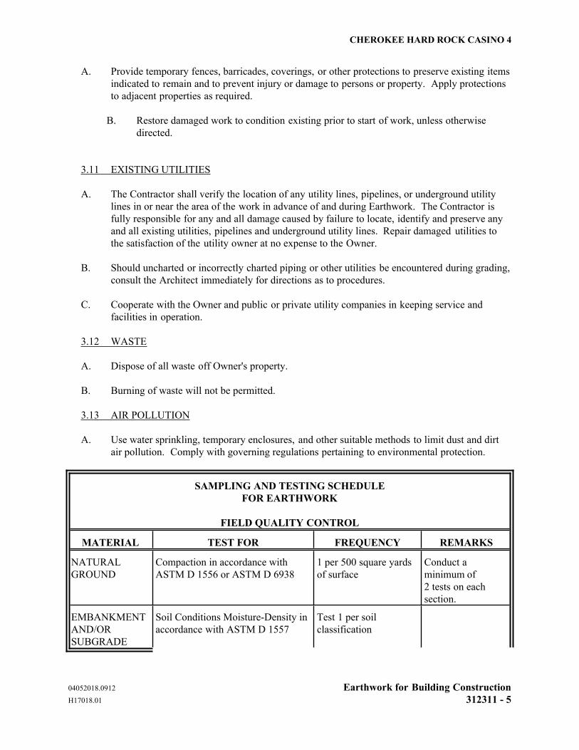
CHEROKEE HARD ROCK CASINO 4
04052018.0912 Earthwork for Building Construction
H17018.01 312311 - 5
A. Provide temporary fences, barricades, coverings, or other protections to preserve existing items
indicated to remain and to prevent injury or damage to persons or property. Apply protections
to adjacent properties as required.
B. Restore damaged work to condition existing prior to start of work, unless otherwise
directed.
3.11 EXISTING UTILITIES
A. The Contractor shall verify the location of any utility lines, pipelines, or underground utility
lines in or near the area of the work in advance of and during Earthwork. The Contractor is
fully responsible for any and all damage caused by failure to locate, identify and preserve any
and all existing utilities, pipelines and underground utility lines. Repair damaged utilities to
the satisfaction of the utility owner at no expense to the Owner.
B. Should uncharted or incorrectly charted piping or other utilities be encountered during grading,
consult the Architect immediately for directions as to procedures.
C. Cooperate with the Owner and public or private utility companies in keeping service and
facilities in operation.
3.12 WASTE
A. Dispose of all waste off Owner's property.
B. Burning of waste will not be permitted.
3.13 AIR POLLUTION
A. Use water sprinkling, temporary enclosures, and other suitable methods to limit dust and dirt
air pollution. Comply with governing regulations pertaining to environmental protection.
SAMPLING AND TESTING SCHEDULE
FOR EARTHWORK
FIELD QUALITY CONTROL
MATERIAL TEST FOR FREQUENCY REMARKS
NATURAL
GROUND
Compaction in accordance with
ASTM D 1556 or ASTM D 6938
1 per 500 square yards
of surface
Conduct a
minimum of
2 tests on each
section.
EMBANKMENT
AND/OR
SUBGRADE
Soil Conditions Moisture-Density in
accordance with ASTM D 1557
Test 1 per soil
classification
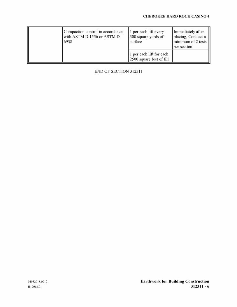
CHEROKEE HARD ROCK CASINO 4
04052018.0912 Earthwork for Building Construction
H17018.01 312311 - 6
1 per each lift every
300 square yards of
surface
Immediately after
placing, Conduct a
minimum of 2 tests
per section
Compaction control in accordance
with ASTM D 1556 or ASTM D
6938
1 per each lift for each
2500 square feet of fill
END OF SECTION 312311
CHEROKEE HARD ROCK CASINO 4
04052018.0914 Drilled Piers
H17018.01 316329 - 1
SECTION 316329 DRILLED PIERS
PART 1 - GENERAL
1.1 RELATED DOCUMENTS
A. Drawings and general provisions of Contract, including Supplemental General Conditions
which apply to work of this section.
1.2 SUMMARY
A. Extent of drilled piers is shown on drawings, including locations, diameters of shafts, bottom
elevations, and details of construction.
1.3 SUBSURFACE SOIL DATA
A. Subsurface soil investigations have been made and the results are available for examination by
the Contractor. The Contractor is expected to examine the site and determine for himself the
character of the materials to be encountered.
1.4 REFERENCES, latest editions of the following:
A. American Concrete Institute (ACI)
1. ACI 301 Specifications for Structural Concrete for Buildings
2. ACI 336.1 Standard Specification for the Construction of Drilled
Piers
B. ASTM International (ASTM)
1. ASTM A 615/ Standard Specification for Deformed and Plain
A 615M Carbon-Steel Bars for Concrete Reinforcement
2. ASTM C 31/ Standard Practice for Making and Curing Concrete
C 31M Test Specimens in the Field
3. ASTM C 39/ Standard Test Method for Compressive Strength of
C 39M Cylindrical Concrete Specimens
4. ASTM C 94/ Standard Specification for Ready-Mixed Concrete
C 94M
5. ASTM C 143/ Standard Test Method for Slump of Hydraulic
C 143M Cement Concrete
6. ASTM C 172-04 Standard Practice for Sampling Freshly Mixed
C172M Concrete
CHEROKEE HARD ROCK CASINO 4
04052018.0914 Drilled Piers
H17018.01 316329 - 2
7. ASTM C 173/ Standard Test Method for Air Content of Freshly
C 173M Mixed Concrete by the Volumetric Method
8. ASTM C 231/ Standard Test Method for Air Content of Freshly
C231M Mixed Concrete by the Pressure Method
9. ASTM C 260/ Standard Specification for Air-Entraining
C260M Admixtures for Concrete
10. ASTM C 494/ Standard Specification for Chemical Admixtures for
C 494M Concrete
1.5 SUBMITTALS
A. Reports: Submit the following reports directly to Engineer, with copy to others as designated.
1. Concrete Materials Test Reports as proposed for use in concrete mixes.
1.6 QUALITY ASSURANCE
A. Codes and Standards: Comply with provisions of American Concrete Institute (ACI)
"Standard Specification for the Construction of Drilled Piers" (ACI 336.1), and as herein
specified.
B. Drilled Pier Installer Qualifications: Not less than three successfully completed contracts with
similar soil conditions, shaft sizes, depths and volumes of work contained in this project.
Submit satisfactory proof of compliance to Engineer.
C. Materials and installed work may require testing and retesting at any time during progress of
work. Allow free access to material stockpiles and facilities. Tests, including retesting of
rejected materials and installed work, will be Contractor's responsibility.
D. Certificates of material properties and compliance with specified requirements may be
submitted in lieu of testing, when acceptable to Engineer. Certificates of compliance must be
signed by materials producer and Contractor.
1.7 JOB CONDITIONS
A. Site Information: Data on indicated subsurface conditions are not intended as representations
or warranties of continuity of such conditions. It is expressly understood that the Owner will
not be responsible for interpretations or conclusions drawn by Contractor. Data is made
available for convenience of Contractor and is not guaranteed to represent conditions that may
be encountered.
B. Additional test borings and other exploratory operations may be made by Contractor at no
additional cost to Owner.
CHEROKEE HARD ROCK CASINO 4
04052018.0914 Drilled Piers
H17018.01 316329 - 3
1.8 EXISTING UTILITIES
A. Locate existing underground utilities by careful hand excavation before starting drilled pier
excavation operations. If utilities are to remain in place, provide protection from damage
during drilled pier operations.
B. Should uncharted or incorrectly charted piping or other utilities be encountered during
excavation, consult Engineer immediately for directions as to procedure. Cooperate with
Owner and or utility companies in keeping services and facilities in operation. Repair
damaged utilities to satisfaction of utility Owner.
C. Do not interrupt existing utilities serving facilities occupied and used by Owner or others,
except when permitted in writing by Owner and after acceptable temporary utility services
have been provided.
PART 2 - PRODUCTS
2.1 CONCRETE AND RELATED MATERIALS:
Concrete and related materials are specified in Division-3 sections.
A. Maximum Aggregate Size: Not larger than three-fourths of minimum clear spacing between
individual reinforcing bars or bundles of bars.
B. Water: Clean, potable.
C. Air-Entraining Admixture: ASTM C 260.
D. Water-Reducing Admixture: ASTM C 494, Type A, containing no set-accelerating or set-
retarding compounds, chlorides, fluorides or nitrates.
E. Reinforcing Bars and Dowels: ASTM A 615, Grade 60.
2.2 CONCRETE MIX DESIGN
A. General: Use independent testing facility for preparing and reporting proposed mix designs.
Testing facility shall not be same as used for field quality control testing.
B. Design mix in accordance with Section 4 of ACI 301 to produce concrete for drilled piers with
minimum 28-day compressive strength of 4000 psi.
C. Admixtures: Use air-entraining admixture in concrete, unless otherwise directed. Add air-
entraining admixture at manufacturer's prescribed rate to result in concrete at point of
placement having 4 percent to 6 percent air content.
D. Slump Limits: Proportion and design mixes to result in concrete slump at point of placement
of 6 inches plus or minus 1 ½ inches.
CHEROKEE HARD ROCK CASINO 4
04052018.0914 Drilled Piers
H17018.01 316329 - 4
2.3 CONCRETE MIXING
A. Ready-Mix Concrete: Comply with requirements of ASTM C 94, and as herein specified.
B. During hot weather, or under conditions contributing to rapid setting of concrete, a shorter
mixing time than specified in ASTM C 94 may be required.
C. When air temperature is between 85 deg.F (30 deg.C) and 90 deg.F (32 deg.C), reduce mixing
and delivery time from 1-1/2 hours to 75 minutes, and when air temperature is above 90 deg.F
(32 deg.C), reduce mixing and delivery time to 60 minutes.
PART 3 - EXECUTION
3.1 DRILLED PIER EXCAVATION
A. General: Excavate holes for drilled piers to elevation as shown on drawings. Drilled pier
design dimensions shown are minimums.
B. Construction Tolerances: Locate centerline of drilled piers within the following tolerances.
1. Maximum permissible variation of location not more than 1/24th of shaft
diameter or 3 inches, whichever is less.
2. Shafts out of plumb:
a. For unreinforced piers extending through materials offering minimal or
no lateral restraint (i.e. water, normally consolidated organic soils, and
soils that might liquefy during an earthquake) - 12.5 percent of pier
diameter.
b. For unreinforced piers extending through materials offering lateral
restraint (soils other than those indicated in a.) - not more than 1.5
percent of pier length.
c. For reinforced concrete shafts - Out-of-plumb tolerance shall be 2.0
percent of the pier length.
3. Concrete cut-off elevation, plus 1 inch to minus 3 inches.
4. If above tolerances are exceeded, provide corrective construction to compensate
for excessive eccentricity. Submit proposed corrective construction methods to
Engineer for review before proceeding.
C. Obstructions: If rock, boulders, or other unforeseen obstructions are encountered which cannot
be removed by standard drilled pier excavation methods, and if such obstructions are not
indicated by available subsurface data, removal of such obstructions will be paid for in
accordance with terms of contract relative to changes in work.
CHEROKEE HARD ROCK CASINO 4
04052018.0914 Drilled Piers
H17018.01 316329 - 5
D. Inspection
1. Each drilled pier must be inspected before placing concrete. The Contractor
shall engage the services of a Registered Professional Geotechnical Engineer
under whose supervision full-time inspection of the drilling and casting of the
piers will be performed.
2. Provide facilities as required to assist inspection of excavations, and cooperate
with inspecting personnel to expedite work.
3. Notify Engineer and testing facility at least 24 hours prior to time excavations
will be drilled.
E. Overexcavation: No payment will be made for extra length, when drilled pier shafts are
excavated to a greater depth than required, due to overdrilling by Contractor. Complete drilled
pier and fill extra depth with concrete, if other conditions are satisfactory. Overexcavated
shafts will be measured and paid for to original design or authorized depth.
3.2 REINFORCING STEEL AND DOWELS
A. Fabricate and erect reinforcing cages in shafts as one continuous unit. Place reinforcement
accurately and symmetrically about axis of hole and hold securely in position during concrete
placement.
B. Use templates to set anchor bolts, leveling plates and other accessories furnished under work of
other sections. Provide blocking and holding devices to maintain required position during
concrete placement.
C. Protect exposed ends of extended reinforcing, dowels, or anchor bolts from mechanical damage
and exposure to weather.
3.3 CONCRETE PLACEMENT
A. General: Fill drilled piers with concrete immediately after inspection and approval by testing
laboratory. Use protection sheets (cut out to receive concrete) over excavation openings,
extending at least 12 inches beyond edge.
B. Place concrete through a hopper centered in the reinforcing cage so that stream of concrete
does not hit reinforcing or sides of hole. Let concrete free-fall for entire depth of shaft. Place
concrete continuously and in a smooth flow without segregating. Provide mechanical vibration
for consolidation of top 5 feet of each shaft.
C. Place concrete in-the-dry unless placing underwater is acceptable to Engineer. If water occurs,
and it is impracticable to dewater drilled pier excavation, and reasonable attempts to seal off
water flow have failed, allow water level to attain its normal level and place concrete by tremie
method. Control placement operations to ensure that tremie is not broken during continuous
placing from bottom to top. Other methods of depositing concrete underwater, such as pump
placement, may be used, subject to the approval of the Engineer.
CHEROKEE HARD ROCK CASINO 4
04052018.0914 Drilled Piers
H17018.01 316329 - 6
D. Stop concrete placement at cut-off elevation shown, screed level, and apply a scoured, rough
finish. Where cut-off elevation is above ground elevation, form top section above grade and
extend shaft to required elevation.
3.4 FIELD QUALITY CONTROL
A. Quality Control Testing During Construction: Sample and test concrete for quality control
during placement, as follows:
1. Sampling Fresh Concrete: ASTM C 172.
2. Slump: ASTM C 143, one test for each concrete load at point of discharge; and
one for each set of compressive strength test specimens.
3. Air Content: ASTM C 173, or ASTM C 231, one for each set of compressive
strength test specimens.
4. Compression Test Specimens: ASTM C 31, one set of 4 standard cylinders for
each compressive strength test, unless otherwise directed. Mold and store
cylinders for laboratory cured test specimens except when field-cure test
specimens are required.
5. Compressive Strength Tests: ASTM C 39, one set of four cylinders for every 30
cubic yards of concrete placed. One specimen tested at 7 days, 2 specimens
tested at 28 days, and one specimen retained in reserve for later testing if
required.
6. Report test results in writing to Engineer and Contractor on same day tests are
made. Include in reports project identification name and number, date of
concrete placement, name of Contractor, name of concrete supplier and truck
number, name of concrete testing service, concrete type, location of drilled pier,
design compressive strength at 28 days, concrete mix proportions and materials;
compressive breaking strength and type of break for both 7-day test and 28-day
tests.
B. Additional Concrete Tests: Testing service may take core samples of in-place concrete when
test results are such that there is reasonable doubt specified concrete strengths have not been
attained.
3.5 INSPECTION AND TESTS FOR DRILLED PIERS
A. Soil testing facility shall perform and report specified tests, and additional tests which may be
required. Conduct tests and provide reports as soon as possible to not delay concreting
operations for acceptable excavations.
END OF SECTION 316329
Related Documents
![MagnumStone - Masters Concrete€¦ · ACI-318, Building Code Requirements for Structural Concrete (ACI 318-02) and Commentary (ACI 318R-02), American Concrete Institute, 2002.].](https://static.cupdf.com/doc/110x72/5e8f550e805e3d1975788f43/magnumstone-masters-aci-318-building-code-requirements-for-structural-concrete.jpg)