SECTION 00 0101 PROJECT TITLE PAGE PROJECT MANUAL FOR BUTLER COUNTY PUBLIC HEALTH ADDITION OWNER: BUTLER COUNTY, IA 428 6TH STREET ALLISON, IA 50602 PROJECT NUMBER: 2112202420 BUTLER COUNTY, IA 610 OAK STREET ALLISON IA 50602 ENGINEER: SHIVE-HATTERY, INC. 222 THIRD AVE. SE, SUITE 300 CEDAR RAPIDS, IA 52401 BIDS DUE: JUNE 30, 2022 2:30 PM 610 OAK STREET ALLISON, IA 50602 NON-MANDATORY PREBID MEETING: JUNE 21, 2022 10:30 AM 610 OAK STREET ALLISON, IA 50602 ISSUED FOR: ISSUED FOR BID JUNE 15, 2022

Welcome message from author
This document is posted to help you gain knowledge. Please leave a comment to let me know what you think about it! Share it to your friends and learn new things together.
Transcript
SECTION 00 0101
PROJECT TITLE PAGE
PROJECT MANUALFOR
BUTLER COUNTY PUBLIC HEALTH ADDITION
OWNER:
BUTLER COUNTY, IA
428 6TH STREET
ALLISON, IA 50602
PROJECT NUMBER: 2112202420
BUTLER COUNTY, IA
610 OAK STREET
ALLISON IA 50602
ENGINEER:
SHIVE-HATTERY, INC.
222 THIRD AVE. SE, SUITE 300
CEDAR RAPIDS, IA 52401
BIDS DUE:
JUNE 30, 2022
2:30 PM
610 OAK STREET
ALLISON, IA 50602
NON-MANDATORY PREBID MEETING:
JUNE 21, 2022
10:30 AM
610 OAK STREET
ALLISON, IA 50602
ISSUED FOR:
ISSUED FOR BID JUNE 15, 2022

END OF SECTION
Butler County Public Health AdditionProject # 2112202420
Issued for Bid June 15, 2022 Project Information00 0102 - 1
SECTION 00 0102 PROJECT INFORMATION
PART 1 GENERAL
1.1 PROJECT IDENTIFICATION
A. The Owner, hereinafter referred to as Owner: Butler County, IA
1.2 PROJECT DESCRIPTION
A. Summary Project Description: The project consists of 4256 sf addition and 1280 sf of garage area to the existing County Emergency Management Building to expand exam rooms, office space, and medical support spaces.
1.3 PROCUREMENT TIMETABLE
A. The Owner reserves the right to change the schedule or terminate the entire procurement process at any time.
1.4 PROCUREMENT DOCUMENTS
A. Availability of Documents: Complete sets of procurement documents may be obtained:
1. From Owner at the Project Manager's address listed above.
PART 2 PRODUCTS (NOT USED)
PART 3 EXECUTION (NOT USED)
END OF SECTION

Butler County Public Health AdditionProject # 2112202420
Issued for Bid June 15, 2022 Certifications Page00 0105 - 1
SECTION 00 0105
CERTIFICATIONS PAGE
I hereby certify that this engineering document was prepared by me or under my direct personal supervision and that I am a duly licensed Professional Engineer under the laws of the State of Iowa.
__________________________________ June 15, 2022Signature DatePrinted or typed name: Matthew K. GordonLicense Number: 19216My license renewal date is: December 31, 2022Pages, Sheets, or Divisions covered by this Seal: 00, 01, 26, 27, 28
I hereby certify that this engineering document was prepared by me or under my direct personal supervision and that I am a duly licensed Professional Engineer under the laws of the State of Iowa.
__________________________________ June 15, 2022Signature DatePrinted or typed name: Jeremy L. HuismanLicense Number: 19258My license renewal date is: December 31, 2022Pages, Sheets, or Divisions covered by this Seal: 22, 23

Butler County Public Health Addition Project # 2112202420
Certifications Page 00 0105 - 2 Issued for Bid June 15, 2022
END OF SECTION
Butler County Public Health Addition Project # 2112202420
Issued for Bid June 15, 2022 TABLE OF CONTENTS00 0110-1
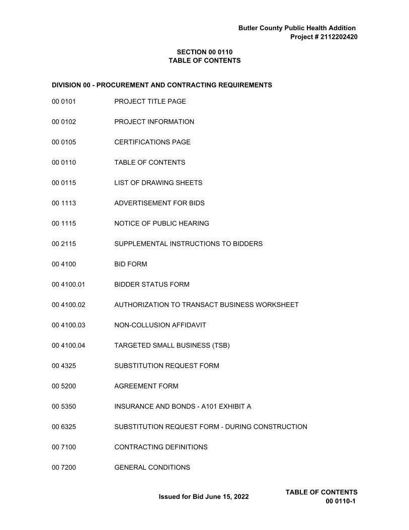
SECTION 00 0110TABLE OF CONTENTS
DIVISION 00 - PROCUREMENT AND CONTRACTING REQUIREMENTS
00 0101 PROJECT TITLE PAGE
00 0102 PROJECT INFORMATION
00 0105 CERTIFICATIONS PAGE
00 0110 TABLE OF CONTENTS
00 0115 LIST OF DRAWING SHEETS
00 1113 ADVERTISEMENT FOR BIDS
00 1115 NOTICE OF PUBLIC HEARING
00 2115 SUPPLEMENTAL INSTRUCTIONS TO BIDDERS
00 4100 BID FORM
00 4100.01 BIDDER STATUS FORM
00 4100.02 AUTHORIZATION TO TRANSACT BUSINESS WORKSHEET
00 4100.03 NON-COLLUSION AFFIDAVIT
00 4100.04 TARGETED SMALL BUSINESS (TSB)
00 4325 SUBSTITUTION REQUEST FORM
00 5200 AGREEMENT FORM
00 5350 INSURANCE AND BONDS - A101 EXHIBIT A
00 6325 SUBSTITUTION REQUEST FORM - DURING CONSTRUCTION
00 7100 CONTRACTING DEFINITIONS
00 7200 GENERAL CONDITIONS
Butler County Public Health Addition Project # 2112202420
TABLE OF CONTENTS 2 – 00 0110 Issued for Bid June 15, 2022
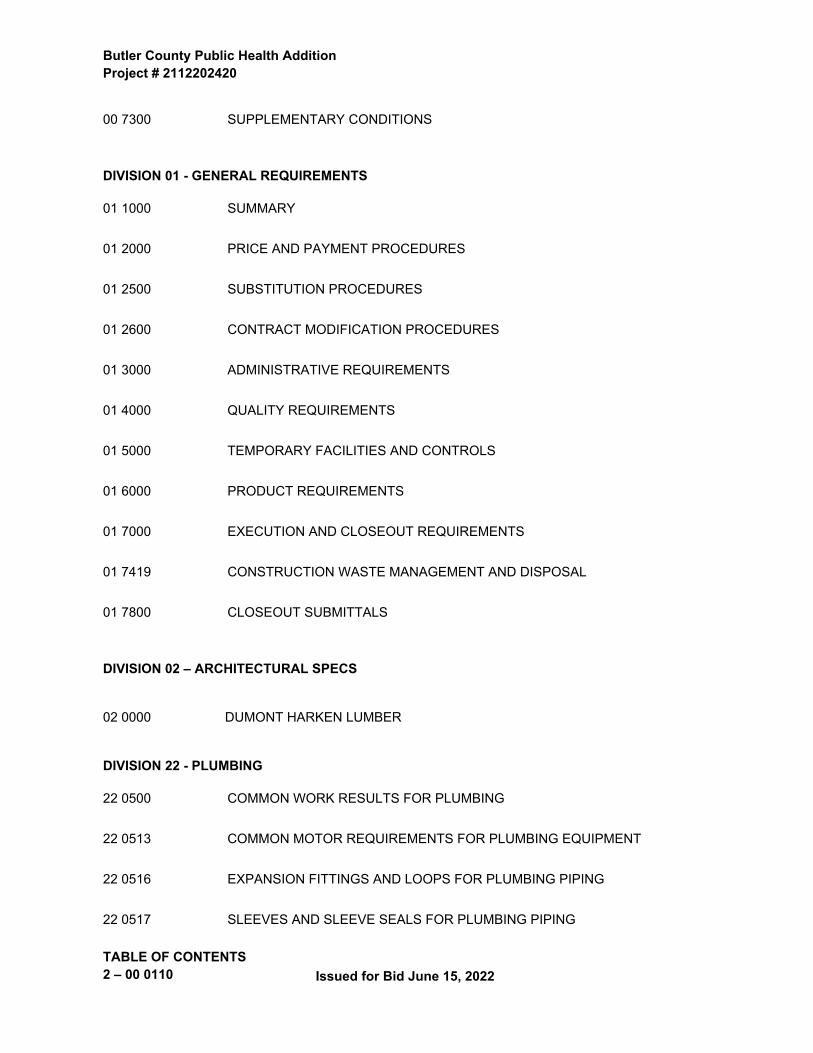
00 7300 SUPPLEMENTARY CONDITIONS
DIVISION 01 - GENERAL REQUIREMENTS
01 1000 SUMMARY
01 2000 PRICE AND PAYMENT PROCEDURES
01 2500 SUBSTITUTION PROCEDURES
01 2600 CONTRACT MODIFICATION PROCEDURES
01 3000 ADMINISTRATIVE REQUIREMENTS
01 4000 QUALITY REQUIREMENTS
01 5000 TEMPORARY FACILITIES AND CONTROLS
01 6000 PRODUCT REQUIREMENTS
01 7000 EXECUTION AND CLOSEOUT REQUIREMENTS
01 7419 CONSTRUCTION WASTE MANAGEMENT AND DISPOSAL
01 7800 CLOSEOUT SUBMITTALS
DIVISION 02 – ARCHITECTURAL SPECS
02 0000 DUMONT HARKEN LUMBER
DIVISION 22 - PLUMBING
22 0500 COMMON WORK RESULTS FOR PLUMBING
22 0513 COMMON MOTOR REQUIREMENTS FOR PLUMBING EQUIPMENT
22 0516 EXPANSION FITTINGS AND LOOPS FOR PLUMBING PIPING
22 0517 SLEEVES AND SLEEVE SEALS FOR PLUMBING PIPING
Butler County Public Health Addition Project # 2112202420
Issued for Bid June 15, 2022 TABLE OF CONTENTS00 0110-3
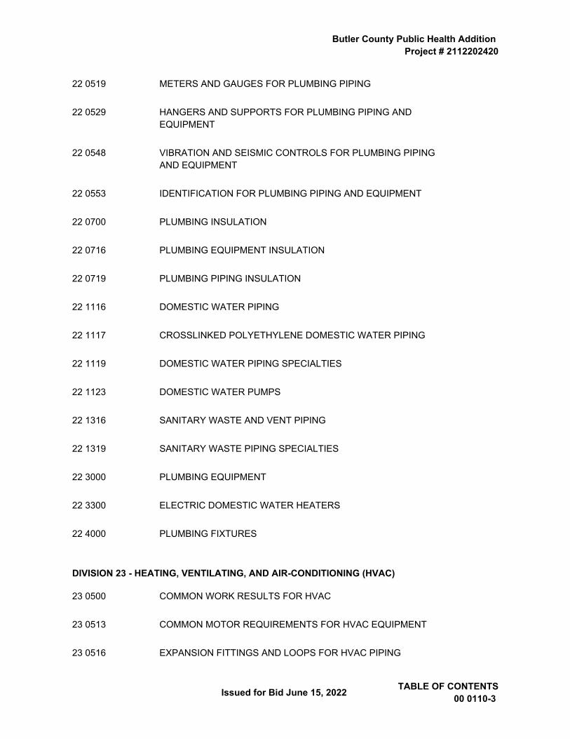
22 0519 METERS AND GAUGES FOR PLUMBING PIPING
22 0529 HANGERS AND SUPPORTS FOR PLUMBING PIPING AND EQUIPMENT
22 0548 VIBRATION AND SEISMIC CONTROLS FOR PLUMBING PIPING AND EQUIPMENT
22 0553 IDENTIFICATION FOR PLUMBING PIPING AND EQUIPMENT
22 0700 PLUMBING INSULATION
22 0716 PLUMBING EQUIPMENT INSULATION
22 0719 PLUMBING PIPING INSULATION
22 1116 DOMESTIC WATER PIPING
22 1117 CROSSLINKED POLYETHYLENE DOMESTIC WATER PIPING
22 1119 DOMESTIC WATER PIPING SPECIALTIES
22 1123 DOMESTIC WATER PUMPS
22 1316 SANITARY WASTE AND VENT PIPING
22 1319 SANITARY WASTE PIPING SPECIALTIES
22 3000 PLUMBING EQUIPMENT
22 3300 ELECTRIC DOMESTIC WATER HEATERS
22 4000 PLUMBING FIXTURES
DIVISION 23 - HEATING, VENTILATING, AND AIR-CONDITIONING (HVAC)
23 0500 COMMON WORK RESULTS FOR HVAC
23 0513 COMMON MOTOR REQUIREMENTS FOR HVAC EQUIPMENT
23 0516 EXPANSION FITTINGS AND LOOPS FOR HVAC PIPING
Butler County Public Health Addition Project # 2112202420
TABLE OF CONTENTS 4 – 00 0110 Issued for Bid June 15, 2022
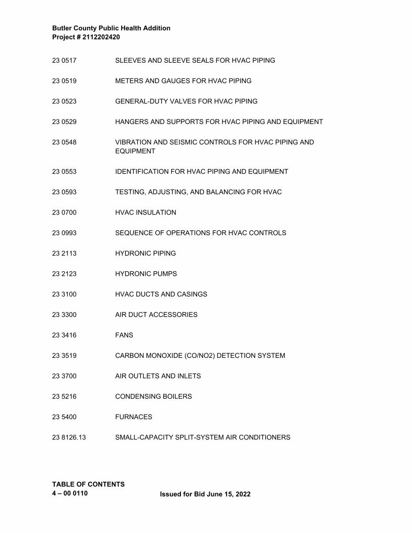
23 0517 SLEEVES AND SLEEVE SEALS FOR HVAC PIPING
23 0519 METERS AND GAUGES FOR HVAC PIPING
23 0523 GENERAL-DUTY VALVES FOR HVAC PIPING
23 0529 HANGERS AND SUPPORTS FOR HVAC PIPING AND EQUIPMENT
23 0548 VIBRATION AND SEISMIC CONTROLS FOR HVAC PIPING AND EQUIPMENT
23 0553 IDENTIFICATION FOR HVAC PIPING AND EQUIPMENT
23 0593 TESTING, ADJUSTING, AND BALANCING FOR HVAC
23 0700 HVAC INSULATION
23 0993 SEQUENCE OF OPERATIONS FOR HVAC CONTROLS
23 2113 HYDRONIC PIPING
23 2123 HYDRONIC PUMPS
23 3100 HVAC DUCTS AND CASINGS
23 3300 AIR DUCT ACCESSORIES
23 3416 FANS
23 3519 CARBON MONOXIDE (CO/NO2) DETECTION SYSTEM
23 3700 AIR OUTLETS AND INLETS
23 5216 CONDENSING BOILERS
23 5400 FURNACES
23 8126.13 SMALL-CAPACITY SPLIT-SYSTEM AIR CONDITIONERS
Butler County Public Health Addition Project # 2112202420
Issued for Bid June 15, 2022 TABLE OF CONTENTS00 0110-5
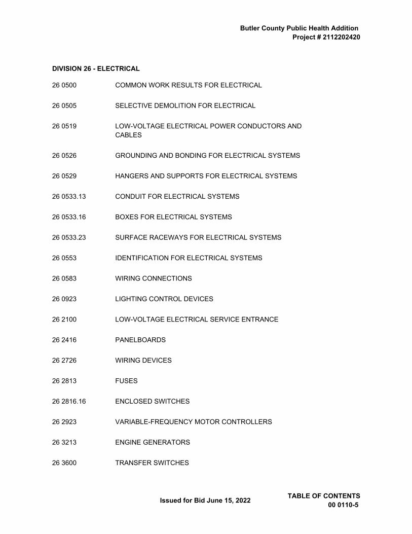
DIVISION 26 - ELECTRICAL
26 0500 COMMON WORK RESULTS FOR ELECTRICAL
26 0505 SELECTIVE DEMOLITION FOR ELECTRICAL
26 0519 LOW-VOLTAGE ELECTRICAL POWER CONDUCTORS AND CABLES
26 0526 GROUNDING AND BONDING FOR ELECTRICAL SYSTEMS
26 0529 HANGERS AND SUPPORTS FOR ELECTRICAL SYSTEMS
26 0533.13 CONDUIT FOR ELECTRICAL SYSTEMS
26 0533.16 BOXES FOR ELECTRICAL SYSTEMS
26 0533.23 SURFACE RACEWAYS FOR ELECTRICAL SYSTEMS
26 0553 IDENTIFICATION FOR ELECTRICAL SYSTEMS
26 0583 WIRING CONNECTIONS
26 0923 LIGHTING CONTROL DEVICES
26 2100 LOW-VOLTAGE ELECTRICAL SERVICE ENTRANCE
26 2416 PANELBOARDS
26 2726 WIRING DEVICES
26 2813 FUSES
26 2816.16 ENCLOSED SWITCHES
26 2923 VARIABLE-FREQUENCY MOTOR CONTROLLERS
26 3213 ENGINE GENERATORS
26 3600 TRANSFER SWITCHES
Butler County Public Health Addition Project # 2112202420
TABLE OF CONTENTS 6 – 00 0110 Issued for Bid June 15, 2022
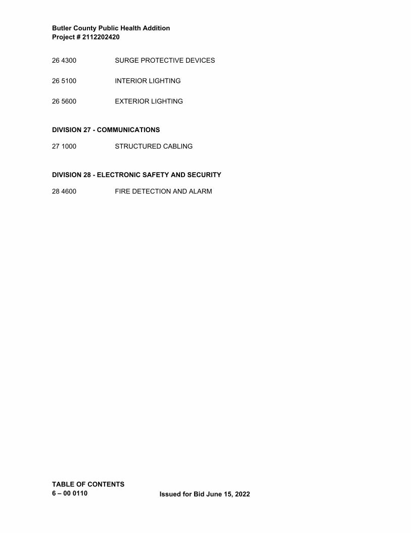
26 4300 SURGE PROTECTIVE DEVICES
26 5100 INTERIOR LIGHTING
26 5600 EXTERIOR LIGHTING
DIVISION 27 - COMMUNICATIONS
27 1000 STRUCTURED CABLING
DIVISION 28 - ELECTRONIC SAFETY AND SECURITY
28 4600 FIRE DETECTION AND ALARM
Butler County Public Health AdditionProject # 2112202420
Issued for Bid June 15, 2022 List of Drawing Sheets00 0115 - 1
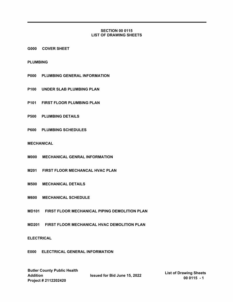
SECTION 00 0115 LIST OF DRAWING SHEETS
G000 COVER SHEET
PLUMBING
P000 PLUMBING GENERAL INFORMATION
P100 UNDER SLAB PLUMBING PLAN
P101 FIRST FLOOR PLUMBING PLAN
P500 PLUMBING DETAILS
P600 PLUMBING SCHEDULES
MECHANICAL
M000 MECHANICAL GENRAL INFORMATION
M201 FIRST FLOOR MECHANCAL HVAC PLAN
M500 MECHANICAL DETAILS
M600 MECHANICAL SCHEDULE
MD101 FIRST FLOOR MECHANICAL PIPING DEMOLITION PLAN
MD201 FIRST FLOOR MECHANICAL HVAC DEMOLITION PLAN
ELECTRICAL
E000 ELECTRICAL GENERAL INFORMATION
Butler County Public Health Addition Project # 2112202420
List of Drawing Sheets 00 0115 - 2 Issued for Bid June 15, 2022
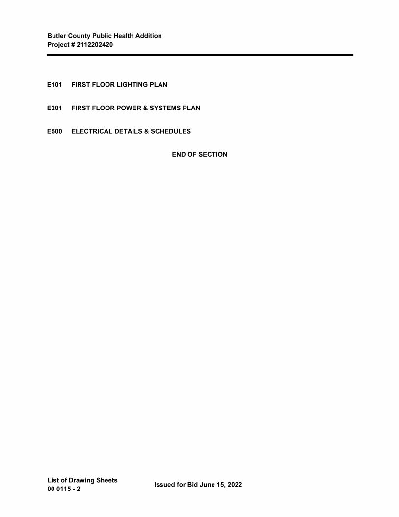
E101 FIRST FLOOR LIGHTING PLAN
E201 FIRST FLOOR POWER & SYSTEMS PLAN
E500 ELECTRICAL DETAILS & SCHEDULES
END OF SECTION
Butler County Public Health AdditionProject # 2112202420
Issued for Bid June 15, 2022 Advertisement for Bids00 1113 - 1
SECTION 00 1113
ADVERTISEMENT FOR BIDS
PROJECT: BUTLER COUNTY PUBLIC HEALTH ADDITION
BUTLER COUNTY PUBLIC HEALTH
BIDS DUE: June 30, 2022 at 2:30 PM
THE Owner (HEREINAFTER REFERRED TO AS Owner ):
Butler County, IA
428 6th Street
Allison, IA 50602
Engineer (hereinafter referred to as Engineer):
Shive-Hattery, Inc.
222 Third Ave. SE, Suite 300
Cedar Rapids, IA 52401
NON-MANDATORY PREBID MEETING: June 21, 2022
TIME: 10:30 AM
LOCATION: 610 Oak Street, Allison, IA 50602
TO: POTENTIAL BIDDERS
Sealed bids will be received by the Owner at 610 Oak Street until 2:30 PM, Central Time, on June 30, 2022.
Sealed bids will be opened and publicly read at the 428 6th Street at 9:00 AM, Central Time, on July 1, 2022 or at such later time and place as may then be fixed.
Bids will be considered by the Owner at a public meeting to be held at 428 6th Street at 9:00 AM, Central Time, on June 14, 2022 or at such later time and place as may then be fixed.
The general nature of the work is as follows:
The project consists of 4256 sf addition and 1280 sf of garage area to the existing County Emergency Management Building to include exam rooms, office space, and medical support spaces for the Public Health Department.
The work must commence on August 1, 2022 and must be completed on May 26, 2023.
Bidding documents may be examined at the Owners office, butlercounty.iowa.gov and at the following location(s):
Butler County Public Health Addition Project # 2112202420
Advertisement for Bids 00 1113 - 2 Issued for Bid June 15, 2022
Rapids Reproductions, DFS Plan Room, Shive-Hattery Custom Portal, rapidsrepro.com 6015 Huntington Ct. NE, Cedar Rapids, IA 52402iSqFt isqft.com 4500 W. Lake Forest Drive Ste. 502, Cincinnati, OH 45242Master Builders of Iowa mbionline.com, 221 Park Street, Des Moines, IA 50309 [email protected]
Copies of the Bidding documents may be obtained by Bidders and Sub-bidders at Rapids Reproductions, DFS Plan Room, Shive-Hattery Custom Portal, rapidsrepro.com 6015 Huntington Ct. NE, Cedar Rapids, IA 52402. There is no deposit. It is requested that bidders return the documents in good condition within ten days after receipt of bids.
All Bidders are required to provide a statement regarding their residency status as required by 875 Iowa Administrative Code Chapter 156.
Contractors using “materials, supplies, and equipment” on projects in designated “exempt entities” may purchase these items without liability for the sales tax. The contractor must have a purchasing agent authorization letter and an exemption certificate from the public entity to present to the retailer, which specifies the construction project and will be available for that project only.
No bid may be withdrawn for a period of 30 days after the date of the scheduled closing time for the receipt of bids.
The Owner seeks to provide opportunities for Targeted Small Businesses in the awarding of contracts and is authorized to award contracts to Targeted Small Businesses per the Iowa Acts of the 73rd General Assembly, 1989 Regular Session, Senate File 2274. For further information about the Targeted Small Business policies, contact the Owner. This project has a target for Targeted Small Business participation of ten percent (10%).
Bidders shall be prepared to submit a performance bond and payment bond and a two-year maintenance bond conditioned on the faithful performance of the contract. Out-of-state bidders shall be prepared to submit an Out-of-State Contractor Bond to the Iowa Division of Labor in accordance with Chapter 91C of the Code of Iowa.
It is the intent of the Owner to award a contract to the lowest responsible, responsive bidder provided the bid has been submitted in accordance with the bidding requirements. The Owner reserves the right to waive informalities or irregularities. The Owner reserves the right to reject any or all bids.
Published by order of the Board of Directors of the Butler County, Iowa.
By: Leslie GroenTitle: Butler County AuditorPublish: June 15, 2022
Submit your offer on the Bid Form provided. Bidders may supplement this form as appropriate.
Butler County Public Health AdditionProject # 2112202420
Issued for Bid June 15, 2022 Notice Of Public Hearing00 1115 - 1
SECTION 00 1115 NOTICE OF PUBLIC HEARING
FOR IOWA CITIES, COUNTIES AND SCHOOL DISTRICTS
BUTLER COUNTY PUBLIC HEALTH ADDITION
BUTLER COUNTY, IA
To Whom It May Concern:
You are hereby notified that at 9:00 AM, Central Time on June 14, 2022, at the 428 6th Street, Allison, IA 50602, there will be a public hearing on the proposed plans, specifications, form of contract, and estimated cost of the project. Any persons interested may appear and file objections to the proposed plans, specifications, form of contract, or cost of such improvement.
The following is a description of the Public Improvement. The project consists of 4256 sf addition and 1280 sf of garage area to the existing County Emergency Management Building to include exam rooms, office space, and medical support spaces for the Public Health Department.
The location of the project is as follows:
Proposed drawings, specifications, and form of contract may be examined at Butler County, IA , during the hours of 8:00 AM to 3:30 PM.
Published by order of the Board of Directors, Butler County, IA.
By: Leslie Groen
Title: Butler County Auditor
Publish: June 8, 2022
END OF SECTION

Butler County Public Health AdditionProject # 2112202420
Issued for Bid June 15, 2022 Supplemental Instructions to
Bidders00 2115 - 1
SECTION 00 2115 SUPPLEMENTAL INSTRUCTIONS TO BIDDERS
ARTICLE 1: DEFINITIONS
No Supplements
ARTICLE 2: BIDDER'S REPRESENTATIONS
Add the following Subparagraphs to Paragraph 2.1:
2.1.5 Work shall commence on or about August 1 , 20 22 , and must be completed by May 26 , 20 23. Modifications to the existing buiolding gas supply (heating) must be complete by November 1, 2022. The new building shall be fully enclosed and ready to be heated (by teporary means) by not later than December 1, 2022.
2.1.6 The Bidder is fully experienced and properly qualified to perform the class of work provided for herein, and that it is properly licensed, equipped, organized and financed to perform such work. The Bidder shall act as an independent contractor and not as the agent of Owner in performing the Contract. The Bidder shall maintain complete control over its employees and all of its subcontractors. Nothing contained in this Contract or any subcontract awarded by Bidder shall create any contractual relationship between any such subcontractor and Owner. The Bidder shall perform all work in accordance with its own methods subject to compliance with the Contract and shall adhere to the schedule of progress and completion deadlines.
2.1.7 The Bidder has included all work associated with the Contract Documents in their Bid, regardless of any direction given by or dictated by any Bid Depositories, other Agencies or Municipalities not specifically party to the Contract. The Bidder shall coordinate the scopes of work to be performed by themselves and their individual Subcontractors prior to bid sufficiently to ensure that all work associated with the Contract Documents, regardless of the Drawing or Specification Section in which they appear, are covered in the Bid.
2.1.8 The Bidder has familiarized themselves with federal, state, and local laws, ordinances, rules and regulations affecting performance of the Work and employment of labor.
Add the following Paragraph 2.2 and Subparagraphs 2.2.1 thru 2.2.3:
2.2. Preference
2.2.1 The State of Iowa, its agencies, and its political subdivisions, including cities, school districts and public utilities are required by Iowa Code Section 73A.21 to require a reciprocal resident bidder and resident labor force preference.
2.2.2 A “Resident Bidder” means a person or entity authorized to transact business in the State of Iowa and having a place of business for transacting business within the state at which it is conducting and has conducted business for at least three years prior to the date of the first advertisement for the public improvement. If another state or foreign country has a more stringent definition of a resident bidder, the more stringent definition is applicable as to bidders from that state or foreign country.
Butler County Public Health Addition Project # 2112202420
Supplemental Instructions to Bidders 00 2115 - 2
Issued for Bid June 15, 2022
2.2.3 A resident bidder shall be allowed a preference as against a nonresident bidder from a state or foreign country other than Iowa if that state our foreign country gives or requires any preference to bidders from that state of foreign country, including but not limited to any preference to bidders, the imposition of any type of labor force preference, or any other form of preferential treatment to bidders or laborers from that state of foreign county. The preference allowed shall be equal to the preference given or required by the state or foreign country in which the nonresident bidder is a resident.
ARTICLE 3: BIDDING DOCUMENTS
Delete Subparagraph 3.1.1 and substitute the following Subparagraph 3.1.1:
Add subparagraphs 3.2.1.1, 3.2.1.2 and 3.2.1.3 as follows:
3.2.1.1 If a discrepancy between different parts of the contract documents exists, the more stringent or higher cost requirement shall apply.
3.2.1.2 Bidders will not be entitled to any additional compensation or any extension of the Contract Time for conditions that can be determined by examining the site and the Bidding and Contract Documents.
3.2.1.3 Prior to bid, it is the responsibility of each bidder, sub-contractor, and material supplier to examine the documents for the work of all trades that may have an effect on the work that the bidder, sub-contractor, or supplier intends to perform.
Add subparagraphs 3.3.2.1 and 3.3.2.2 as follows:
3.3.2.1 Substitution requests must be submitted by prospective bidders on 00 4325 - Substitution Request Form. Substitution requests from manufacturers, distributors, or other entities that are not bidding as a general contractor will be rejected without review.
3.3.2.2 Approval of a substitution request does not in any way diminish the contractor's obligation to meet the specified requirements or the Engineer's design intent.
Delete Subparagraph 3.4.3 and replace with the following:
3.4.3 Addenda will be issued in order to be received by all planholders of record not less than 48 Hours prior to the date and time that bids are due, except an addendum withdrawing the Request for Bids or one which includes postponement of the date for receipt of bids.
ARTICLE 4: BIDDING PROCEDURES
4.1 Preparation of Bids
Delete Subparagraph 4.1.5 and replace with the following:
4.1.5 All Alternates are not required to be bid. Insert language from the Schedule of Bid Prices or from the Bid Form that describes how Alternates are to be bid.
Add the following Subparagraph 4.1.9:
Butler County Public Health Addition Project # 2112202420
Issued for Bid June 15, 2022 Supplemental Instructions to
Bidders00 2115 - 3
4.1.9 The Contractor shall take note and comply with all governing laws, rules, and regulations affecting the Work. This may include such laws, rules, and regulations as:
4.1.9.1. Licensing of Contractors for special requirements, e.g. hazardous waste removal.
4.1.9.2. Requirements for special construction permits.
4.1.9.3. Exemption from sales tax, if applicable.
4.1.9.4. Wage rates and employment requirements when required by law or by Owner.
4.1.9.5. Local labor requirements.
4.1.9.6. Non-discriminatory hiring practices.
4.1.9.7. Targeted small business participation.
4.2 Bid Security
Delete Subparagraph 4.2.1 and substitute the following Subparagraph:
4.2.1 Each Bidder shall accompany the bid with a bid security, in a separate envelope, as security that the successful Bidder will enter into a Contract for the work bid upon and will furnish after the award of the Contract, a corporate surety bond or bonds, acceptable to the Owner, for the faithful performance of the Contract, in an amount equivalent to 100% of the amount of the Contract. The Bidder's security shall be in an amount equivalent to 5% of the Bid Amount, and shall be in the form of a cashier's or certified check drawn on a bank in Iowa or a bank chartered under the laws of the United States, or a certified share draft drawn on a credit union in Iowa or chartered under the laws of the United States or a bid bond from a corporate surety satisfactory to the Owner. Should the Bidder refuse to enter into such Contract or fail to furnish such bonds, the amount of the bid security shall be forfeited to the Owner as liquidated damages, not as a penalty. The amount of the bid security shall not be forfeited to the Owner in the event the Owner fails to comply with Paragraph 6.2. Bid security of the successful bidder will be held by the Owner until an Agreement is fully executed and bonds are received and acceptable to the Owner.
4.3 Submission of Bids
Delete Subparagraph 4.3.1 and substitute the following Subparagraphs 4.3.1 and Subparagraph(s):
4.3.1 All copies of the Bid and other documents, not including the bid security, required to be submitted with the Bid, shall be enclosed in a sealed opaque envelope. The bid security, if any, shall be submitted in a separate sealed opaque envelope. Each envelope shall bear the return address of the bidder and shall be addressed as follows:
TO: Butler County, IA
Address: 610 Oak Street, Allison, IA 50602
BID FOR: Butler County Public Health Addition
or as applicable:
Butler County Public Health Addition Project # 2112202420
Supplemental Instructions to Bidders 00 2115 - 4
Issued for Bid June 15, 2022
BID SECURITY FOR: Butler County Public Health Addition
4.3.1.a Each bidder who is not a Targeted Small Business (TSB) and who will be using a TSB subcontractor or supplier shall submit with the bid on the Targeted Small Business Participation Form provided herein, the name(s) of Iowa Targeted Small Business(es) to which a subcontract will be awarded, a description of the work to be performed, and the dollar amount assigned to the work to be performed.
4.3.1.b If a prime contractor fails to meet the Targeted Small Business participation goal indicated, the prime contractor shall provide a list of Targeted Small Business(es) contacted on the Targeted Small Business Contact Form provided herein.
4.3.1.c If the Bid, the bid security, if any, and other documents required to be submitted with the Bid are sent by mail, the sealed envelopes shall be enclosed in a separate mail envelope with the notation "SEALED BID ENCLOSED" on the face thereof.
4.4 Modification or Withdrawal of Bid
Add Subparagraph 4.4.1.1 as follows:
4.4.1.1 The specific time period during which Bids may not be withdrawn shall be as stated on the Bid Form bound herein.
Add Article 4.5 Pre-Bid Conference as follows:
4.5 Pre-Bid Conference
4.4.5 The Advertisement for Bid includes notification of a non-mandatory pre-bid conference for the purpose of answering questions and providing information to prospective Bidders. The pre-bid conference will be held at 610 Oak Street, Allison, IA 50602 on June 21, 2022 at 10:30 AM.
ARTICLE 5: CONSIDERATION OF BIDS
5.1 Opening of Bids
Paragraph 5.1 No Supplements
Delete subparagraph 5.3.1 and substitute the following subparagraph:
5.3.1 It is the intent of the Owner to award a contract or multiple contracts to the lowest responsible, responsive Bidder(s) provided the Bid(s) has/have been submitted in accordance with the requirements of the Bidding Documents and does/do not exceed the funds available. The Owner shall have the right to waive informalities and irregularities in a Bid or Bids received and to accept the Bid(s) which, in the Owner’s judgment, is/are in the Owner’s best interests.
ARTICLE 6: POST-BID INFORMATION
Add Subparagraph 6.1.1 as follows:
Butler County Public Health Addition Project # 2112202420
Issued for Bid June 15, 2022 Supplemental Instructions to
Bidders00 2115 - 5
6.1.1 Out-of-state-bidders shall furnish documentation prior to execution of the Agreement that confirms the Bidder is in compliance with Chapter 91C Construction Contractors and Chapter 490 Business Corporation Division XV Foreign Corporations of the Code of Iowa.
ARTICLE 7: PERFORMANCE BOND AND PAYMENT BOND
No Supplements.
ARTICLE 8: FORM OF AGREEMENT BETWEEN OWNER AND CONTRACTOR
Add the following Paragraph 8.1 Execution of Agreement:
8.1 The selected Bidder shall, within ten (10) calendar days after receipt of Notice of Award, sign and deliver the required number of executed counterparts of the Agreement along with any required attached documents. Within ten (10) calendar days after receipt of executed documents from the selected Bidder, the Owner shall deliver one fully executed counterpart to the Contractor.
END OF SECTION

Butler County Public Health AdditionProject # 2112202420
Issued for Bid June 15, 2022 Bid Form00 4100 - 1
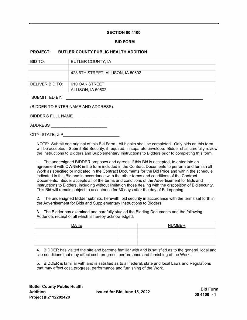
SECTION 00 4100
BID FORM
PROJECT: BUTLER COUNTY PUBLIC HEALTH ADDITION
BID TO: BUTLER COUNTY, IA
428 6TH STREET, ALLISON, IA 50602
DELIVER BID TO: 610 OAK STREETALLISON, IA 50602
SUBMITTED BY: _____________________________________________________________
(BIDDER TO ENTER NAME AND ADDRESS).
BIDDER'S FULL NAME _________________________
ADDRESS _________________________
CITY, STATE, ZIP_________________________
NOTE: Submit one original of this Bid Form. All blanks shall be completed. Only bids on this form will be accepted. Submit Bid Security, if required, in separate envelope. Bidder shall carefully review the Instructions to Bidders and Supplementary Instructions to Bidders prior to completing this form.
1. The undersigned BIDDER proposes and agrees, if this Bid is accepted, to enter into an agreement with OWNER in the form included in the Contract Documents to perform and furnish all Work as specified or indicated in the Contract Documents for the Bid Price and within the schedule indicated in this Bid and in accordance with the other terms and conditions of the Contract Documents. Bidder accepts all of the terms and conditions of the Advertisement for Bids and Instructions to Bidders, including without limitation those dealing with the disposition of Bid security. This Bid will remain subject to acceptance for 30 days after the day of Bid opening.
2. The undersigned Bidder submits, herewith, bid security in accordance with the terms set forth in the Advertisement for Bids and Supplementary Instructions to Bidders.
3. The Bidder has examined and carefully studied the Bidding Documents and the following Addenda, receipt of all which is hereby acknowledged:
DATE NUMBER
4. BIDDER has visited the site and become familiar with and is satisfied as to the general, local and site conditions that may affect cost, progress, performance and furnishing of the Work.
5. BIDDER is familiar with and is satisfied as to all federal, state and local Laws and Regulations that may affect cost, progress, performance and furnishing of the Work.
Butler County Public Health Addition Project # 2112202420
Bid Form 00 4100 - 2 Issued for Bid June 15, 2022
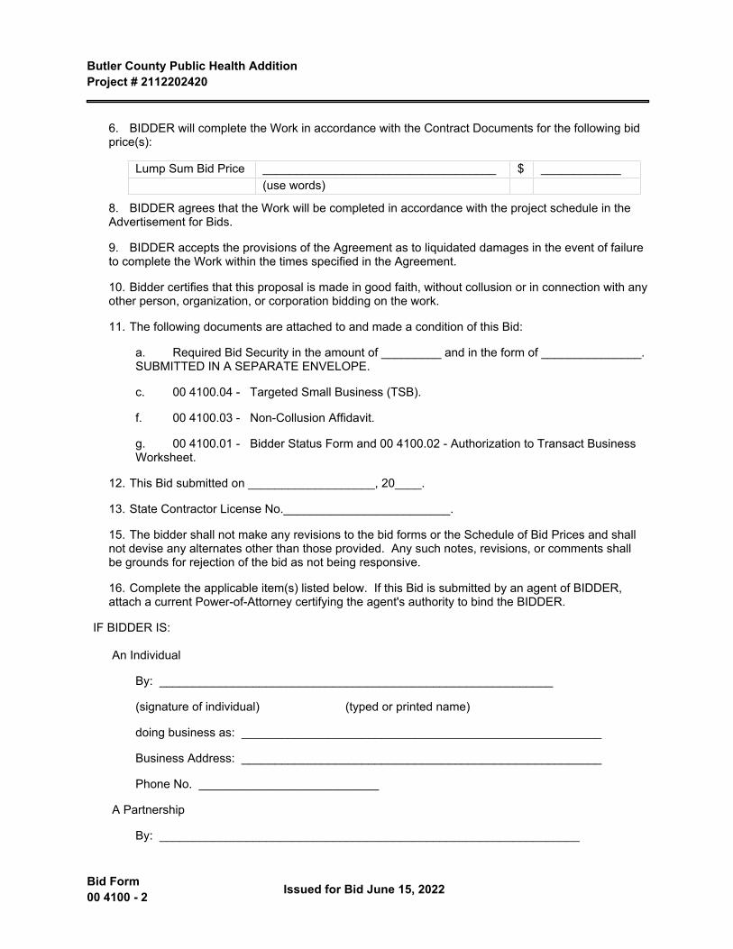
6. BIDDER will complete the Work in accordance with the Contract Documents for the following bid price(s):
Lump Sum Bid Price ___________________________________ $ ____________(use words)
8. BIDDER agrees that the Work will be completed in accordance with the project schedule in the Advertisement for Bids.
9. BIDDER accepts the provisions of the Agreement as to liquidated damages in the event of failure to complete the Work within the times specified in the Agreement.
10. Bidder certifies that this proposal is made in good faith, without collusion or in connection with any other person, organization, or corporation bidding on the work.
11. The following documents are attached to and made a condition of this Bid:
a. Required Bid Security in the amount of _________ and in the form of _______________. SUBMITTED IN A SEPARATE ENVELOPE.
c. 00 4100.04 - Targeted Small Business (TSB).
f. 00 4100.03 - Non-Collusion Affidavit.
g. 00 4100.01 - Bidder Status Form and 00 4100.02 - Authorization to Transact Business Worksheet.
12. This Bid submitted on ___________________, 20____.
13. State Contractor License No._________________________.
15. The bidder shall not make any revisions to the bid forms or the Schedule of Bid Prices and shall not devise any alternates other than those provided. Any such notes, revisions, or comments shall be grounds for rejection of the bid as not being responsive.
16. Complete the applicable item(s) listed below. If this Bid is submitted by an agent of BIDDER, attach a current Power-of-Attorney certifying the agent's authority to bind the BIDDER.
IF BIDDER IS:
An Individual
By: ___________________________________________________________
(signature of individual) (typed or printed name)
doing business as: ______________________________________________________
Business Address: ______________________________________________________
Phone No. ___________________________
A Partnership
By: _______________________________________________________________
Butler County Public Health Addition Project # 2112202420
Issued for Bid June 15, 2022 Bid Form00 4100 - 3
(Firm Name)
________________________________________________________________
(signature of general partner) (typed or printed name)
Business Address: ______________________________________________________
Phone No. _____________________________
A Corporation
By: ________________________________________________________________
(Corporation Name)
State of Incorporation: ____________________________________________________
By: ________________________________________________________________
(signature of person authorized to sign)
________________________________________________________________
(typed or printed name and title)
Attest: ________________________________________________________________
(Secretary)
Business Address: _______________________________________________________
Phone No. ______________________________
END OF SECTION

Butler County Public Health AdditionProject # 2112202420
Issued for Bid June 15, 2022 Bidder Status Form00 4100.01 - 1
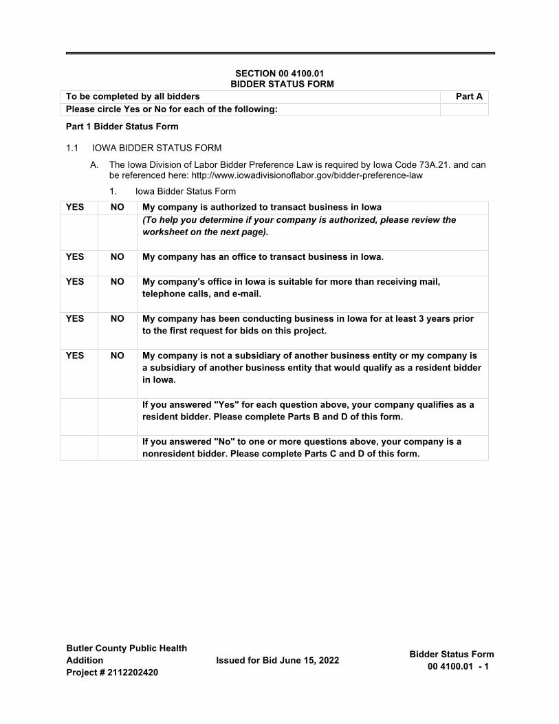
SECTION 00 4100.01 BIDDER STATUS FORM
To be completed by all bidders Part APlease circle Yes or No for each of the following:
Part 1 Bidder Status Form
1.1 IOWA BIDDER STATUS FORM
A. The Iowa Division of Labor Bidder Preference Law is required by Iowa Code 73A.21. and can be referenced here: http://www.iowadivisionoflabor.gov/bidder-preference-law
1. Iowa Bidder Status Form
YES NO My company is authorized to transact business in Iowa(To help you determine if your company is authorized, please review the worksheet on the next page).
YES NO My company has an office to transact business in Iowa.
YES NO My company's office in Iowa is suitable for more than receiving mail, telephone calls, and e-mail.
YES NO My company has been conducting business in Iowa for at least 3 years prior to the first request for bids on this project.
YES NO My company is not a subsidiary of another business entity or my company is a subsidiary of another business entity that would qualify as a resident bidder in Iowa.
If you answered "Yes" for each question above, your company qualifies as a resident bidder. Please complete Parts B and D of this form.
If you answered "No" to one or more questions above, your company is a nonresident bidder. Please complete Parts C and D of this form.
Butler County Public Health Addition Project # 2112202420
Bidder Status Form 00 4100.01 - 2 Issued for Bid June 15, 2022
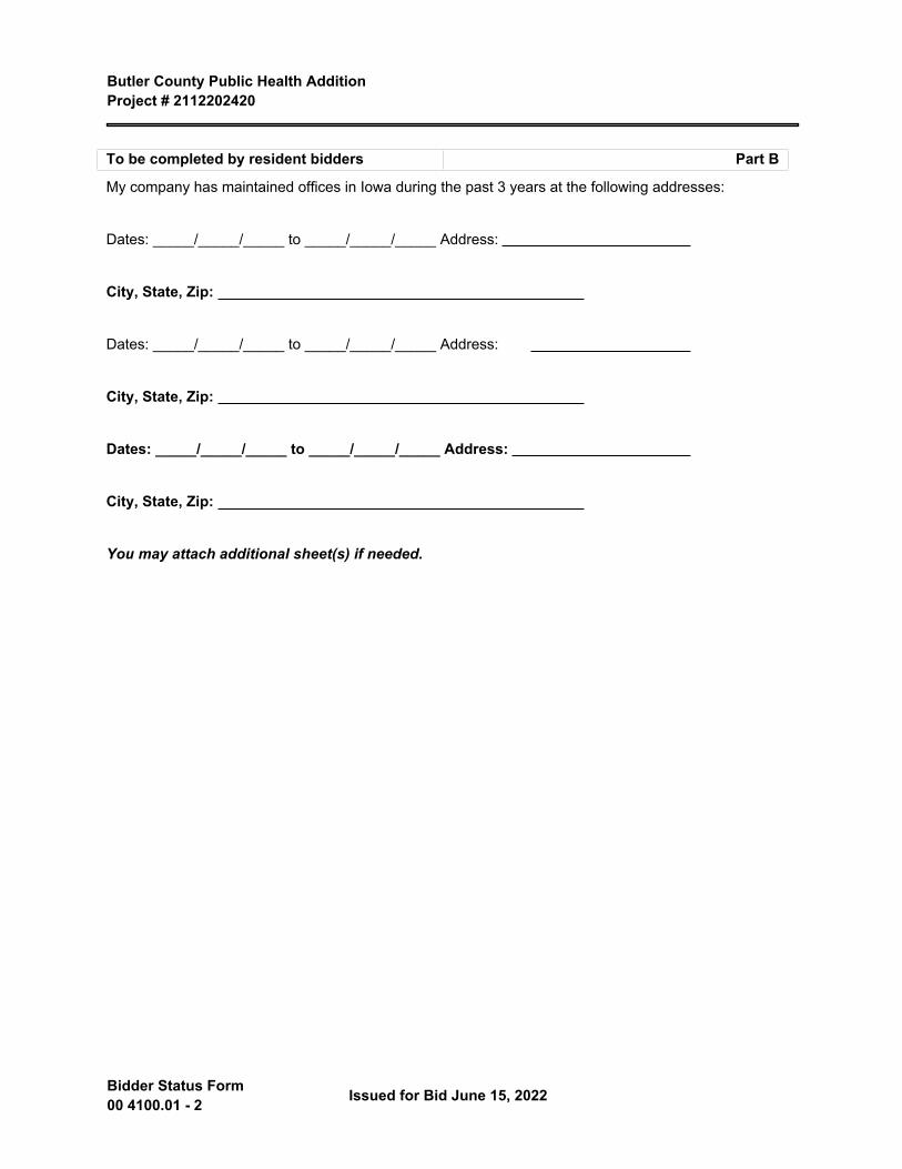
To be completed by resident bidders Part B
My company has maintained offices in Iowa during the past 3 years at the following addresses:
Dates: _____/_____/_____ to _____/_____/_____ Address:
City, State, Zip:
Dates: _____/_____/_____ to _____/_____/_____ Address:
City, State, Zip:
Dates: _____/_____/_____ to _____/_____/_____ Address:
City, State, Zip:
You may attach additional sheet(s) if needed.
Butler County Public Health Addition Project # 2112202420
Issued for Bid June 15, 2022 Bidder Status Form00 4100.01 - 3
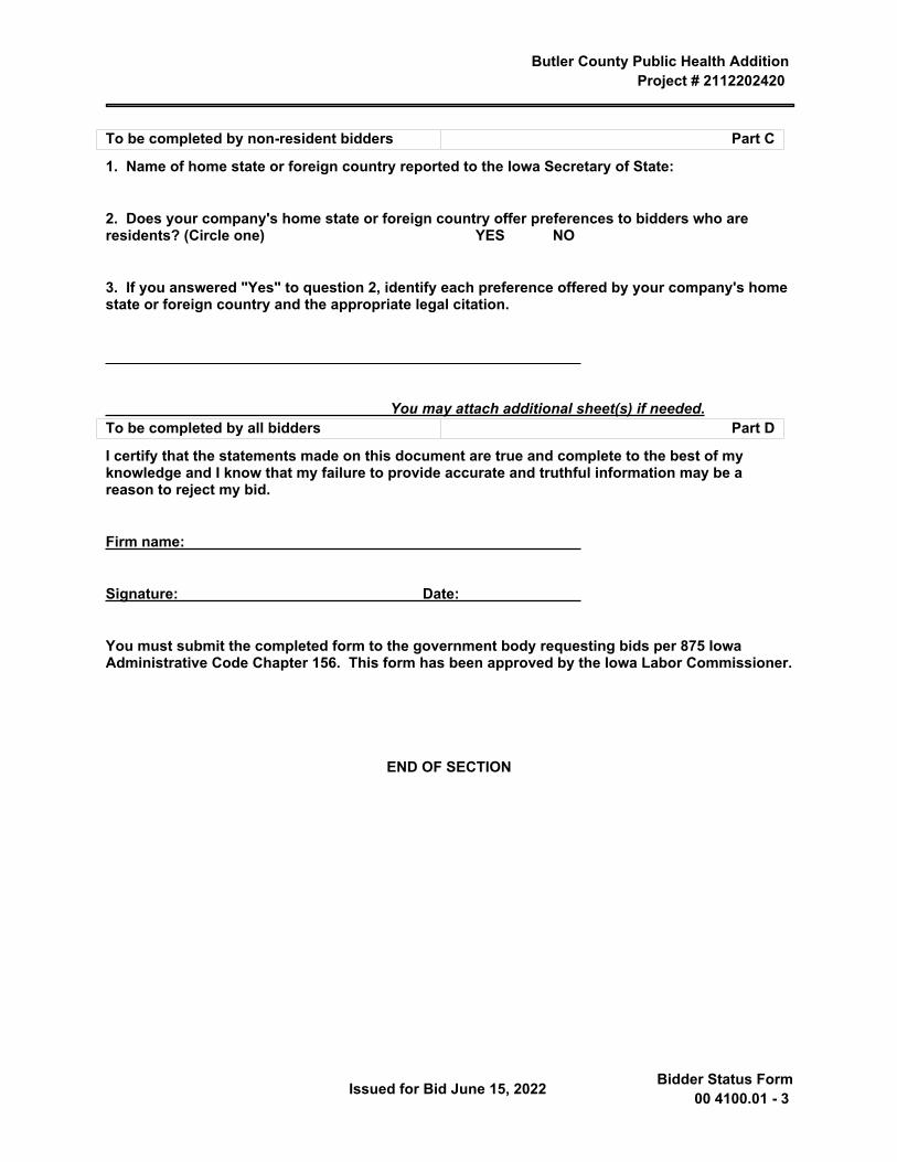
To be completed by non-resident bidders Part C
1. Name of home state or foreign country reported to the Iowa Secretary of State:
2. Does your company's home state or foreign country offer preferences to bidders who are residents? (Circle one) YES NO
3. If you answered "Yes" to question 2, identify each preference offered by your company's home state or foreign country and the appropriate legal citation.
You may attach additional sheet(s) if needed.To be completed by all bidders Part D
I certify that the statements made on this document are true and complete to the best of my knowledge and I know that my failure to provide accurate and truthful information may be a reason to reject my bid.
Firm name:
Signature: Date:
You must submit the completed form to the government body requesting bids per 875 Iowa Administrative Code Chapter 156. This form has been approved by the Iowa Labor Commissioner.
END OF SECTION

Butler County Public Health AdditionProject # 2112202420
Issued for Bid June 15, 2022 Authorization to Transact
Business Worksheet00 4100.02 - 1
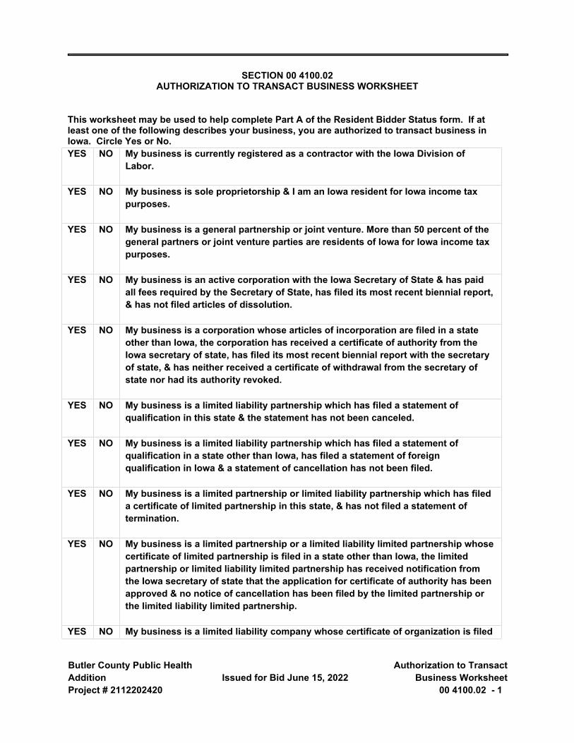
SECTION 00 4100.02 AUTHORIZATION TO TRANSACT BUSINESS WORKSHEET
This worksheet may be used to help complete Part A of the Resident Bidder Status form. If at least one of the following describes your business, you are authorized to transact business in Iowa. Circle Yes or No.YES NO My business is currently registered as a contractor with the Iowa Division of
Labor.
YES NO My business is sole proprietorship & I am an Iowa resident for Iowa income tax purposes.
YES NO My business is a general partnership or joint venture. More than 50 percent of the general partners or joint venture parties are residents of Iowa for Iowa income tax purposes.
YES NO My business is an active corporation with the Iowa Secretary of State & has paid all fees required by the Secretary of State, has filed its most recent biennial report, & has not filed articles of dissolution.
YES NO My business is a corporation whose articles of incorporation are filed in a state other than Iowa, the corporation has received a certificate of authority from the Iowa secretary of state, has filed its most recent biennial report with the secretary of state, & has neither received a certificate of withdrawal from the secretary of state nor had its authority revoked.
YES NO My business is a limited liability partnership which has filed a statement of qualification in this state & the statement has not been canceled.
YES NO My business is a limited liability partnership which has filed a statement of qualification in a state other than Iowa, has filed a statement of foreign qualification in Iowa & a statement of cancellation has not been filed.
YES NO My business is a limited partnership or limited liability partnership which has filed a certificate of limited partnership in this state, & has not filed a statement of termination.
YES NO My business is a limited partnership or a limited liability limited partnership whose certificate of limited partnership is filed in a state other than Iowa, the limited partnership or limited liability limited partnership has received notification from the Iowa secretary of state that the application for certificate of authority has been approved & no notice of cancellation has been filed by the limited partnership or the limited liability limited partnership.
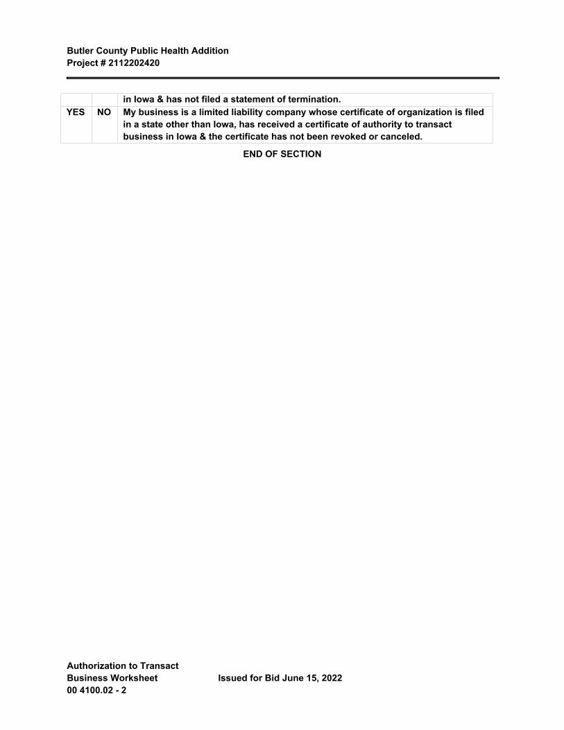
YES NO My business is a limited liability company whose certificate of organization is filed
Butler County Public Health Addition Project # 2112202420
Authorization to Transact Business Worksheet 00 4100.02 - 2
Issued for Bid June 15, 2022
in Iowa & has not filed a statement of termination.YES NO My business is a limited liability company whose certificate of organization is filed
in a state other than Iowa, has received a certificate of authority to transact business in Iowa & the certificate has not been revoked or canceled.
END OF SECTION
Butler County Public Health AdditionProject # 2112202420
Issued for Bid June 15, 2022 Non-Collusion Affidavit00 4100.03 - 1
SECTION 00 4100.03
NON-COLLUSION AFFIDAVIT
The undersigned bidder or agent, being duly sworn on oath, says that he/she has not, nor has any other member, representative, or agent of the firm, company, corporation or partnership represented by him, entered into any combination, collusion or agreement with any person relative to the price to be bid by anyone at such letting nor to prevent any person from bidding nor to include anyone to refrain from bidding, and that this bid is made without reference to any other bid and without any agreement, understanding or combination with any other person in reference to such bidding.
He/She further says that no person or persons, firms, or corporation has, have or will receive directly or indirectly, any rebate, fee gift, commission or thing of value on account of such sale.
OATH AND AFFIRMATION
I HEREBY AFFIRM UNDER THE PENALTIES FOR PERJURY THAT THE FACTS AND INFORMATION CONTAINED IN THE FOREGOING BID FOR PUBLIC WORKS ARE TRUE AND CORRECT.
Dated this _______ day of _____________________________, ___________________.
Name of organization: _____________________________________________________
Title of person signing: _____________________________________________________
Signature: _______________________________________________________________
ACKNOWLEDGEMENT
STATE OF __________________________________)
COUNTY OF ________________________________)
Before me, a Notary Public, personally appeared the above named and swore that the statements contained in the foregoing document are true and correct.
SUBSCRIBED AND SWORN TO ME THIS _______ DAY OF _____________________________,
Butler County Public Health Addition Project # 2112202420
Non-Collusion Affidavit 00 4100.03 - 2 Issued for Bid June 15, 2022
Notary Public Signature: ______________________________________________
My Commission Expires: ______________________________________________
END OF SECTION
Butler County Public Health AdditionProject # 2112202420
Issued for Bid June 15, 2022 Targeted Small Business (TSB)00 4100.04 - 1
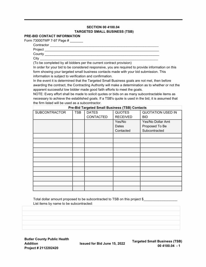
SECTION 00 4100.04 TARGETED SMALL BUSINESS (TSB)
PRE-BID CONTACT INFORMATIONForm 730007WP 7-97 Page # _______
Contractor __________________________________________________________Project _____________________________________________________________County _____________________________________________________________City _______________________________________________________________(To be completed by all bidders per the current contract provision)In order for your bid to be considered responsive, you are required to provide information on this form showing your targeted small business contacts made with your bid submission. This information is subject to verification and confirmation.In the event it is determined that the Targeted Small Business goals are not met, then before awarding the contract, the Contracting Authority will make a determination as to whether or not the apparent successful low bidder made good faith efforts to meet the goals.NOTE: Every effort shall be made to solicit quotes or bids on as many subcontractable items as necessary to achieve the established goals. If a TSB's quote is used in the bid, it is assumed that the firm listed will be used as a subcontractor.
Pre-Bid Targeted Small Business (TSB) ContactsSUBCONTRACTOR TSB DATES
CONTACTEDQUOTES RECEIVED
QUOTATION USED IN BID
Yes/NoDates Contacted
Yes/No Dollar Amt Proposed To Be Subcontracted
Total dollar amount proposed to be subcontracted to TSB on this project $__________________List items by name to be subcontracted:
Butler County Public Health Addition Project # 2112202420
Targeted Small Business (TSB) 00 4100.04 - 2 Issued for Bid June 15, 2022
END OF SECTION
Butler County Public Health AdditionProject # 2112202420
Issued for Bid June 15, 2022 Substitution Request Form00 4325 - 1
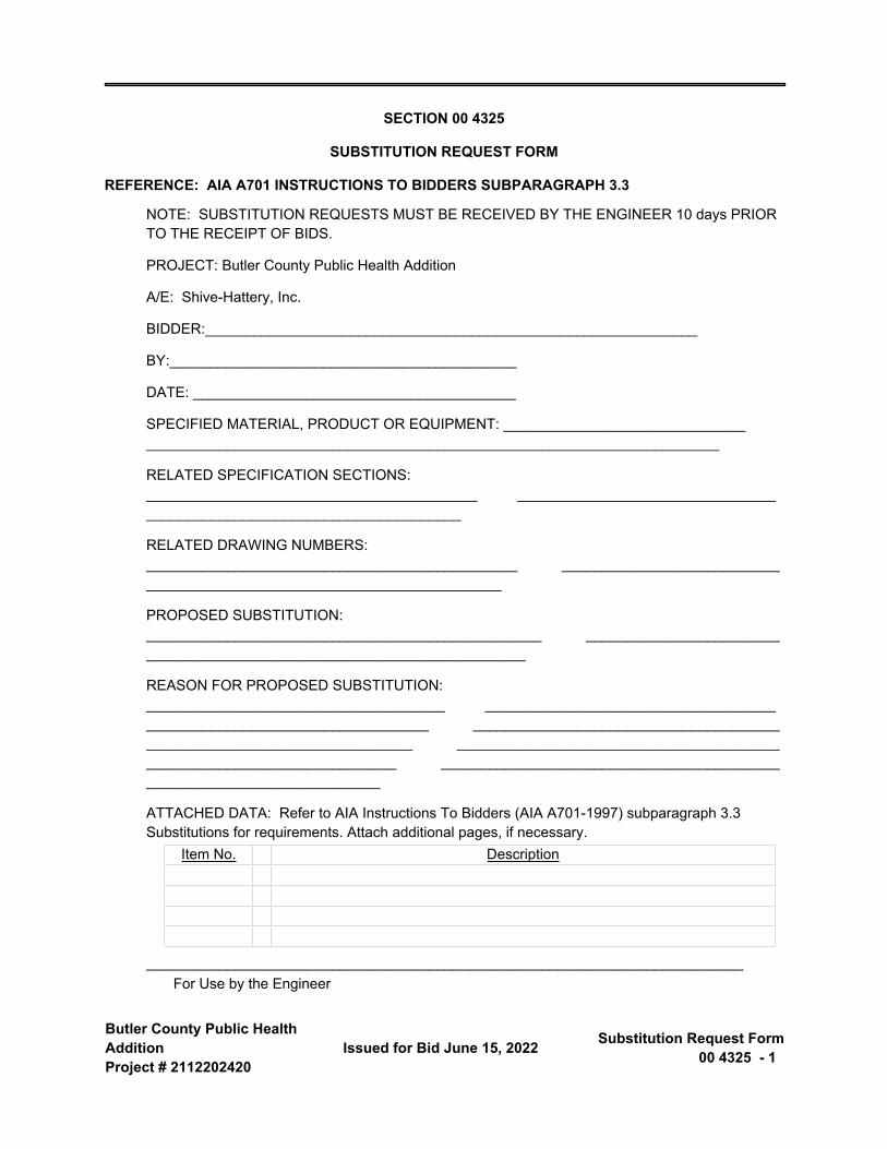
SECTION 00 4325
SUBSTITUTION REQUEST FORM
REFERENCE: AIA A701 INSTRUCTIONS TO BIDDERS SUBPARAGRAPH 3.3
NOTE: SUBSTITUTION REQUESTS MUST BE RECEIVED BY THE ENGINEER 10 days PRIOR TO THE RECEIPT OF BIDS.
PROJECT: Butler County Public Health Addition
A/E: Shive-Hattery, Inc.
BIDDER:_____________________________________________________________
BY:___________________________________________
DATE: ________________________________________
SPECIFIED MATERIAL, PRODUCT OR EQUIPMENT: ______________________________ _______________________________________________________________________
RELATED SPECIFICATION SECTIONS: _________________________________________ _______________________________________________________________________
RELATED DRAWING NUMBERS: ______________________________________________ _______________________________________________________________________
PROPOSED SUBSTITUTION: _________________________________________________ _______________________________________________________________________
REASON FOR PROPOSED SUBSTITUTION: _____________________________________ _______________________________________________________________________ _______________________________________________________________________ _______________________________________________________________________ _______________________________________________________________________
ATTACHED DATA: Refer to AIA Instructions To Bidders (AIA A701-1997) subparagraph 3.3 Substitutions for requirements. Attach additional pages, if necessary.
Item No. Description
__________________________________________________________________________For Use by the Engineer
Butler County Public Health Addition Project # 2112202420
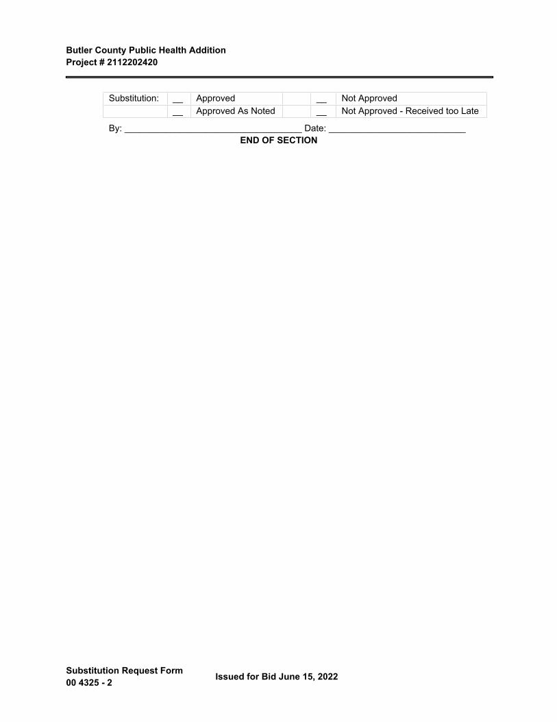
Substitution Request Form 00 4325 - 2 Issued for Bid June 15, 2022
Substitution: __ Approved __ Not Approved__ Approved As Noted __ Not Approved - Received too Late
By: ___________________________________ Date: ___________________________END OF SECTION
Butler County Public Health AdditionProject # 2112202420
Issued for Bid June 15, 2022 Agreement Form00 5200 - 1
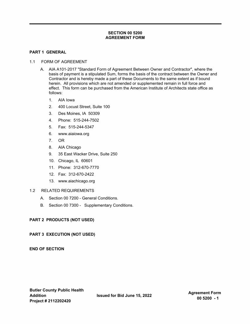
SECTION 00 5200 AGREEMENT FORM
PART 1 GENERAL
1.1 FORM OF AGREEMENT
A. AIA A101-2017 "Standard Form of Agreement Between Owner and Contractor", where the basis of payment is a stipulated Sum, forms the basis of the contract between the Owner and Contractor and is hereby made a part of these Documents to the same extent as if bound herein. All provisions which are not amended or supplemented remain in full force and effect. This form can be purchased from the American Institute of Architects state office as follows:
1. AIA Iowa2. 400 Locust Street, Suite 1003. Des Moines, IA 503094. Phone: 515-244-75025. Fax: 515-244-53476. www.aiaiowa.org7. OR8. AIA Chicago9. 35 East Wacker Drive, Suite 25010. Chicago, IL 6060111. Phone: 312-670-777012. Fax: 312-670-242213. www.aiachicago.org
1.2 RELATED REQUIREMENTS
A. Section 00 7200 - General Conditions.
B. Section 00 7300 - Supplementary Conditions.
PART 2 PRODUCTS (NOT USED)
PART 3 EXECUTION (NOT USED)
END OF SECTION

Butler County Public Health AdditionProject # 2112202420
Issued for Bid June 15, 2022 Insurance and Bonds - A101
Exhibit A00 5350 - 1
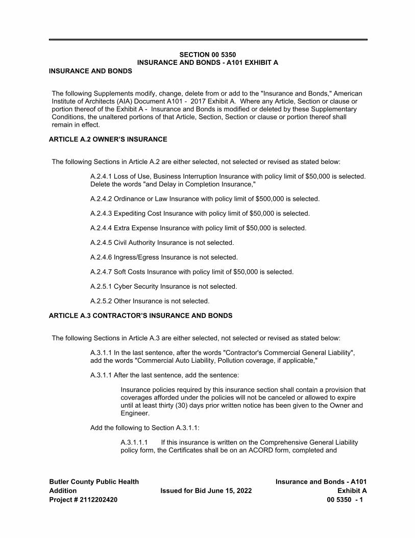
SECTION 00 5350 INSURANCE AND BONDS - A101 EXHIBIT A
INSURANCE AND BONDS
The following Supplements modify, change, delete from or add to the "Insurance and Bonds," American Institute of Architects (AIA) Document A101 - 2017 Exhibit A. Where any Article, Section or clause or portion thereof of the Exhibit A - Insurance and Bonds is modified or deleted by these Supplementary Conditions, the unaltered portions of that Article, Section, Section or clause or portion thereof shall remain in effect.
ARTICLE A.2 OWNER’S INSURANCE
The following Sections in Article A.2 are either selected, not selected or revised as stated below:
A.2.4.1 Loss of Use, Business Interruption Insurance with policy limit of $50,000 is selected. Delete the words "and Delay in Completion Insurance,"
A.2.4.2 Ordinance or Law Insurance with policy limit of $500,000 is selected.
A.2.4.3 Expediting Cost Insurance with policy limit of $50,000 is selected.
A.2.4.4 Extra Expense Insurance with policy limit of $50,000 is selected.
A.2.4.5 Civil Authority Insurance is not selected.
A.2.4.6 Ingress/Egress Insurance is not selected.
A.2.4.7 Soft Costs Insurance with policy limit of $50,000 is selected.
A.2.5.1 Cyber Security Insurance is not selected.
A.2.5.2 Other Insurance is not selected.
ARTICLE A.3 CONTRACTOR’S INSURANCE AND BONDS
The following Sections in Article A.3 are either selected, not selected or revised as stated below:
A.3.1.1 In the last sentence, after the words "Contractor's Commercial General Liability", add the words "Commercial Auto Liability, Pollution coverage, if applicable,"
A.3.1.1 After the last sentence, add the sentence:
Insurance policies required by this insurance section shall contain a provision that coverages afforded under the policies will not be canceled or allowed to expire until at least thirty (30) days prior written notice has been given to the Owner and Engineer.
Add the following to Section A.3.1.1:
A.3.1.1.1 If this insurance is written on the Comprehensive General Liability policy form, the Certificates shall be on an ACORD form, completed and
Butler County Public Health Addition Project # 2112202420
Insurance and Bonds - A101 Exhibit A 00 5350 - 2
Issued for Bid June 15, 2022
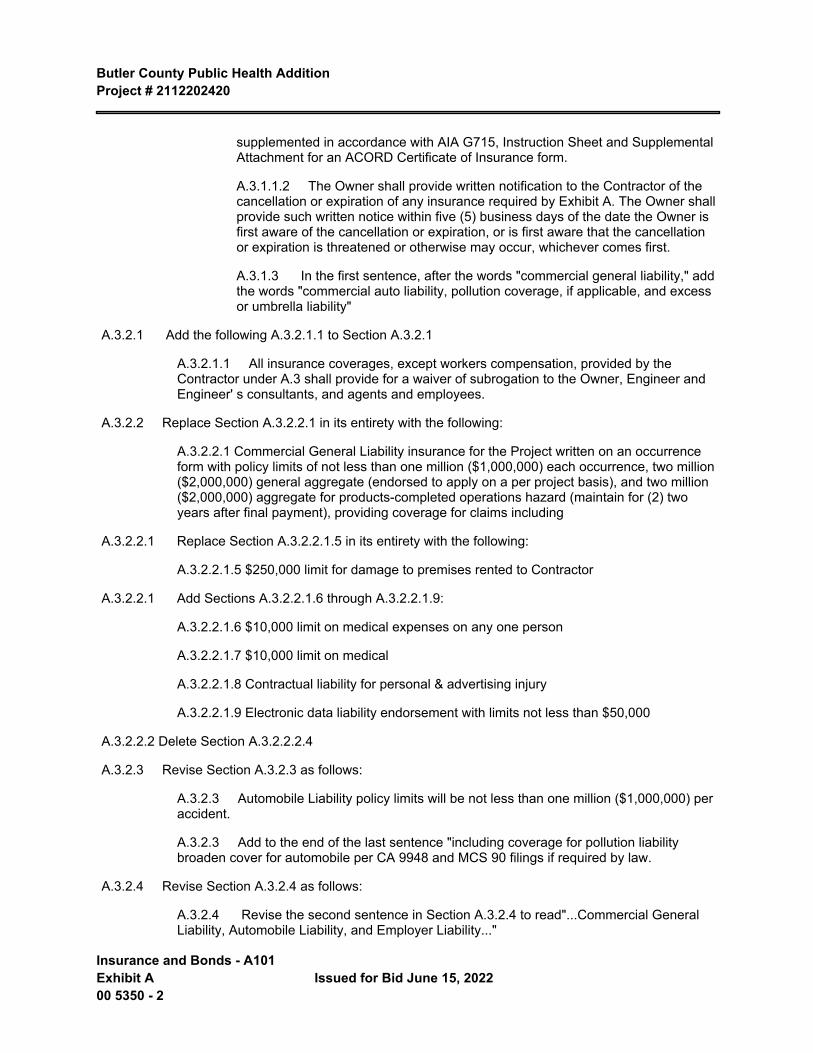
supplemented in accordance with AIA G715, Instruction Sheet and Supplemental Attachment for an ACORD Certificate of Insurance form.
A.3.1.1.2 The Owner shall provide written notification to the Contractor of the cancellation or expiration of any insurance required by Exhibit A. The Owner shall provide such written notice within five (5) business days of the date the Owner is first aware of the cancellation or expiration, or is first aware that the cancellation or expiration is threatened or otherwise may occur, whichever comes first.
A.3.1.3 In the first sentence, after the words "commercial general liability," add the words "commercial auto liability, pollution coverage, if applicable, and excess or umbrella liability"
A.3.2.1 Add the following A.3.2.1.1 to Section A.3.2.1
A.3.2.1.1 All insurance coverages, except workers compensation, provided by the Contractor under A.3 shall provide for a waiver of subrogation to the Owner, Engineer and Engineer' s consultants, and agents and employees.
A.3.2.2 Replace Section A.3.2.2.1 in its entirety with the following:
A.3.2.2.1 Commercial General Liability insurance for the Project written on an occurrence form with policy limits of not less than one million ($1,000,000) each occurrence, two million ($2,000,000) general aggregate (endorsed to apply on a per project basis), and two million ($2,000,000) aggregate for products-completed operations hazard (maintain for (2) two years after final payment), providing coverage for claims including
A.3.2.2.1 Replace Section A.3.2.2.1.5 in its entirety with the following:
A.3.2.2.1.5 $250,000 limit for damage to premises rented to Contractor
A.3.2.2.1 Add Sections A.3.2.2.1.6 through A.3.2.2.1.9:
A.3.2.2.1.6 $10,000 limit on medical expenses on any one person
A.3.2.2.1.7 $10,000 limit on medical
A.3.2.2.1.8 Contractual liability for personal & advertising injury
A.3.2.2.1.9 Electronic data liability endorsement with limits not less than $50,000
A.3.2.2.2 Delete Section A.3.2.2.2.4
A.3.2.3 Revise Section A.3.2.3 as follows:
A.3.2.3 Automobile Liability policy limits will be not less than one million ($1,000,000) per accident.
A.3.2.3 Add to the end of the last sentence "including coverage for pollution liability broaden cover for automobile per CA 9948 and MCS 90 filings if required by law.
A.3.2.4 Revise Section A.3.2.4 as follows:
A.3.2.4 Revise the second sentence in Section A.3.2.4 to read"...Commercial General Liability, Automobile Liability, and Employer Liability..."
Butler County Public Health Addition Project # 2112202420
Issued for Bid June 15, 2022 Insurance and Bonds - A101
Exhibit A00 5350 - 3
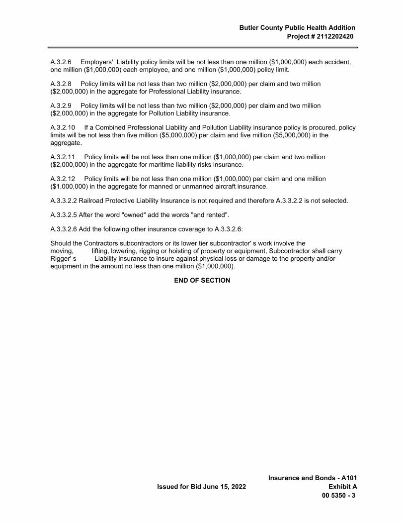
A.3.2.6 Employers' Liability policy limits will be not less than one million ($1,000,000) each accident, one million ($1,000,000) each employee, and one million ($1,000,000) policy limit.
A.3.2.8 Policy limits will be not less than two million ($2,000,000) per claim and two million ($2,000,000) in the aggregate for Professional Liability insurance.
A.3.2.9 Policy limits will be not less than two million ($2,000,000) per claim and two million ($2,000,000) in the aggregate for Pollution Liability insurance.
A.3.2.10 If a Combined Professional Liability and Pollution Liability insurance policy is procured, policy limits will be not less than five million ($5,000,000) per claim and five million ($5,000,000) in the aggregate.
A.3.2.11 Policy limits will be not less than one million ($1,000,000) per claim and two million ($2,000,000) in the aggregate for maritime liability risks insurance.
A.3.2.12 Policy limits will be not less than one million ($1,000,000) per claim and one million ($1,000,000) in the aggregate for manned or unmanned aircraft insurance.
A.3.3.2.2 Railroad Protective Liability Insurance is not required and therefore A.3.3.2.2 is not selected.
A.3.3.2.5 After the word "owned" add the words "and rented".
A.3.3.2.6 Add the following other insurance coverage to A.3.3.2.6:
Should the Contractors subcontractors or its lower tier subcontractor' s work involve the moving, lifting, lowering, rigging or hoisting of property or equipment, Subcontractor shall carry Rigger' s Liability insurance to insure against physical loss or damage to the property and/or equipment in the amount no less than one million ($1,000,000).
END OF SECTION

Butler County Public Health AdditionProject # 2112202420
Issued for Bid June 15, 2022 Substitution Request Form -
During Construction00 6325 - 1
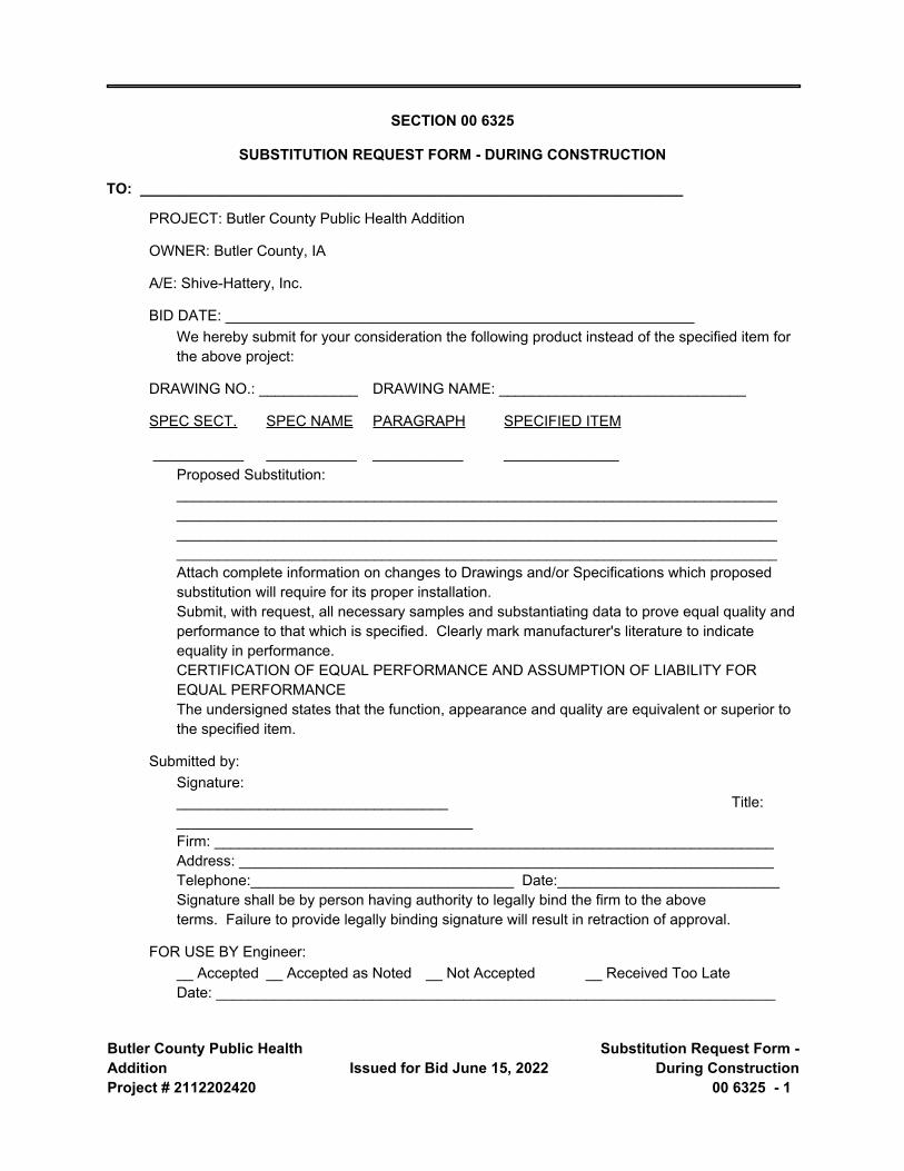
SECTION 00 6325
SUBSTITUTION REQUEST FORM - DURING CONSTRUCTION
TO: __________________________________________________________________
PROJECT: Butler County Public Health Addition
OWNER: Butler County, IA
A/E: Shive-Hattery, Inc.
BID DATE: _________________________________________________________We hereby submit for your consideration the following product instead of the specified item for the above project:
DRAWING NO.: ____________ DRAWING NAME: ______________________________
SPEC SECT. SPEC NAME PARAGRAPH SPECIFIED ITEM
___________ ___________ ___________ ______________Proposed Substitution: _________________________________________________________________________ _________________________________________________________________________ _________________________________________________________________________ _________________________________________________________________________Attach complete information on changes to Drawings and/or Specifications which proposed substitution will require for its proper installation.Submit, with request, all necessary samples and substantiating data to prove equal quality and performance to that which is specified. Clearly mark manufacturer's literature to indicate equality in performance.CERTIFICATION OF EQUAL PERFORMANCE AND ASSUMPTION OF LIABILITY FOR EQUAL PERFORMANCEThe undersigned states that the function, appearance and quality are equivalent or superior to the specified item.
Submitted by:Signature: _________________________________ Title: ____________________________________Firm: ____________________________________________________________________Address: _________________________________________________________________Telephone:________________________________ Date:___________________________Signature shall be by person having authority to legally bind the firm to the above terms. Failure to provide legally binding signature will result in retraction of approval.
FOR USE BY Engineer:__ Accepted __ Accepted as Noted __ Not Accepted __ Received Too LateDate: ____________________________________________________________________
Butler County Public Health Addition Project # 2112202420
Substitution Request Form - During Construction 00 6325 - 2
Issued for Bid June 15, 2022
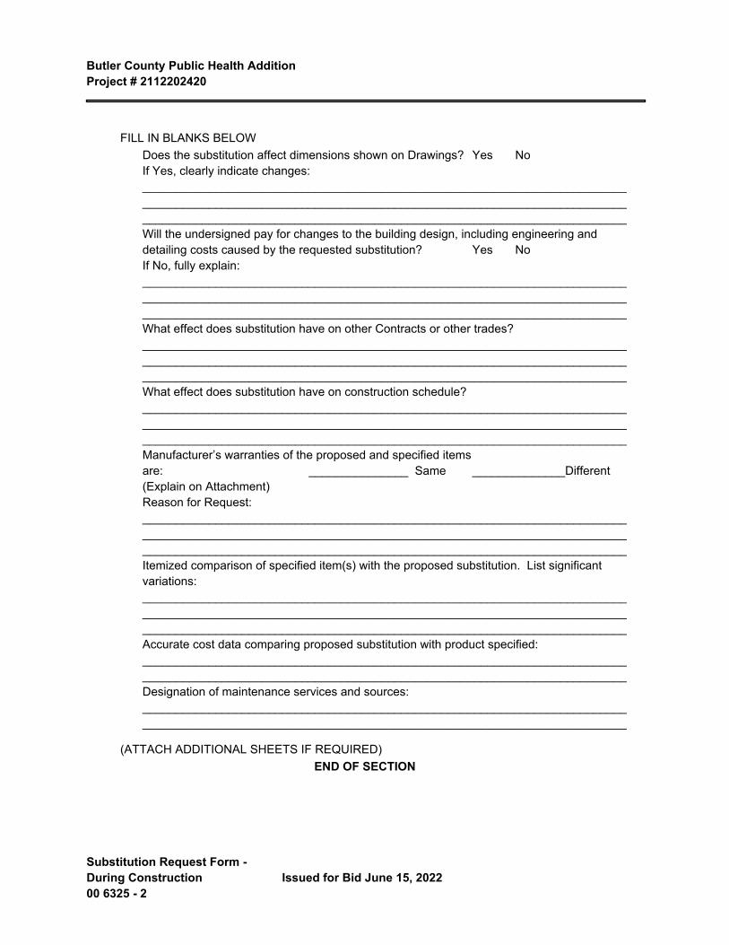
FILL IN BLANKS BELOWDoes the substitution affect dimensions shown on Drawings? Yes NoIf Yes, clearly indicate changes: _________________________________________________________________________ _________________________________________________________________________ _________________________________________________________________________Will the undersigned pay for changes to the building design, including engineering and detailing costs caused by the requested substitution? Yes NoIf No, fully explain: _________________________________________________________________________ _________________________________________________________________________ _________________________________________________________________________What effect does substitution have on other Contracts or other trades? _________________________________________________________________________ _________________________________________________________________________ _________________________________________________________________________What effect does substitution have on construction schedule? _________________________________________________________________________ _________________________________________________________________________ _________________________________________________________________________Manufacturer’s warranties of the proposed and specified items are: _______________ Same ______________Different (Explain on Attachment)Reason for Request: _________________________________________________________________________ _________________________________________________________________________ _________________________________________________________________________Itemized comparison of specified item(s) with the proposed substitution. List significant variations: _________________________________________________________________________ _________________________________________________________________________ _________________________________________________________________________Accurate cost data comparing proposed substitution with product specified: _________________________________________________________________________ _________________________________________________________________________Designation of maintenance services and sources: _________________________________________________________________________ _________________________________________________________________________
(ATTACH ADDITIONAL SHEETS IF REQUIRED)END OF SECTION
Butler County Public Health AdditionProject # 2112202420
Issued for Bid June 15, 2022 Contracting Definitions00 7100 - 1
SECTION 00 7100 CONTRACTING DEFINITIONS
PART 1 GENERAL
1.1 APPLICABILITY: THESE DEFINITIONS ARE INTEGRAL TO THE AGREEMENT.
1.2 DEFINITIONS - DESIGN-BUILD DOCUMENTS
A. Contract Documents: As defined in the Conditions of the Contract and as follows:
1. At the time of execution of the Agreement, Contract Documents consist of the following:
a. The Agreement and Conditions of the Contract, and other documents listed on the Table of Contents under the heading Contracting Requirements.
2. From time to time after execution of the Agreement, upon approval by the Owner, the following types of documents will be incorporated into Contract Documents:
a. Drawings and other documents documenting the design.
b. Construction drawings and specifications detailing the execution of the design.
B. Project Program: The Owner's requirements for size, arrangement, organization, and location of functional spaces , description of space functions, identification of fittings, equipment, and furnishings, description of the physical and environmental requirements for each space, together with a description of the image, goals, or "mission" of the project.
1.3 DEFINITIONS - TIME PERIODS AND MILESTONE DATES
A. Preliminary Design: The time period during which the design criteria are finalized and preliminary drawings and written descriptions are prepared to illustrate the proposed design of the work or a portion of the work to the Owner, as described in the Conditions of the Contract.
B. Design Development: The time period during which the form, arrangement, size, and materials of the work or a portion of the work are determinedas described in the Conditions of the Contract.
C. Construction Documents: The time period during which process working drawings, specifications, and other documents describing the work or a portion of the work are prepared in sufficient detail to allow accurate and complete construction.
D. Construction: The time period from the beginning of work on the project site until final payment as defined by the Conditions of the Contract.
E. Substantial Completion: The date as defined in the Conditions of the Contract. Date of Substantial Completion is the due date for the following:
1. Design-Builder's complete punchlist of items to be completed.2. Owner's complete punchlist of items to be completed.3. Compliance with requirements of governing authorities, for submittals, inspections, and
permits.4. Compliance with Owner's requirements for access to areas occupied by the Owner.
F. Closeout: The time period during which all details of both construction and commissioning are completed.
Butler County Public Health Addition Project # 2112202420
Contracting Definitions 00 7100 - 2 Issued for Bid June 15, 2022
1. The Closeout period is the time from Date of Substantial Completion until final payment, both as defined by the Conditions of the Contract.
2. Before and during the Closeout period, the Owner will ascertain whether the completed project complies with Contract Documents.
G. Occupancy: The time period during which the project is occupied for its intended purpose.
1. The Occupancy period begins at Date of Substantial Completion, as defined by the Conditions of the Contract.
H. Correction Period: The time period defined by the Conditions of the Contract.
PART 2 PRODUCTS - NOT USED
PART 3 EXECUTION - NOT USED
END OF SECTION
Butler County Public Health AdditionProject # 2112202420
Issued for Bid June 15, 2022 General Conditions00 7200 - 1
SECTION 00 7200
GENERAL CONDITIONS
FORM OF GENERAL CONDITIONS
AIA A201-2017 "General Conditions of the Contract for Construction" is the General Conditions between the Owner and the Contractor and is hereby made a part of these documents to the same extent as if bound herein. The document can be purchased from the American Institute of Architects state office as follows:
AIA Iowa400 Locust Street, Suite 100
Des Moines, IA 50309Phone: 515-244-7502
Fax: 515-244-5347www.aiaiowa.org
OR
AIA Chicago35 East Wacker Drive, Suite 250
Chicago, IL 60601Phone: 312-670-7770
Fax: 312-670-2422www.aiachicago.org
END OF SECTION

Butler County Public Health AdditionProject # 2112202420
Issued for Bid June 15, 2022 Supplementary Conditions00 7300 - 1
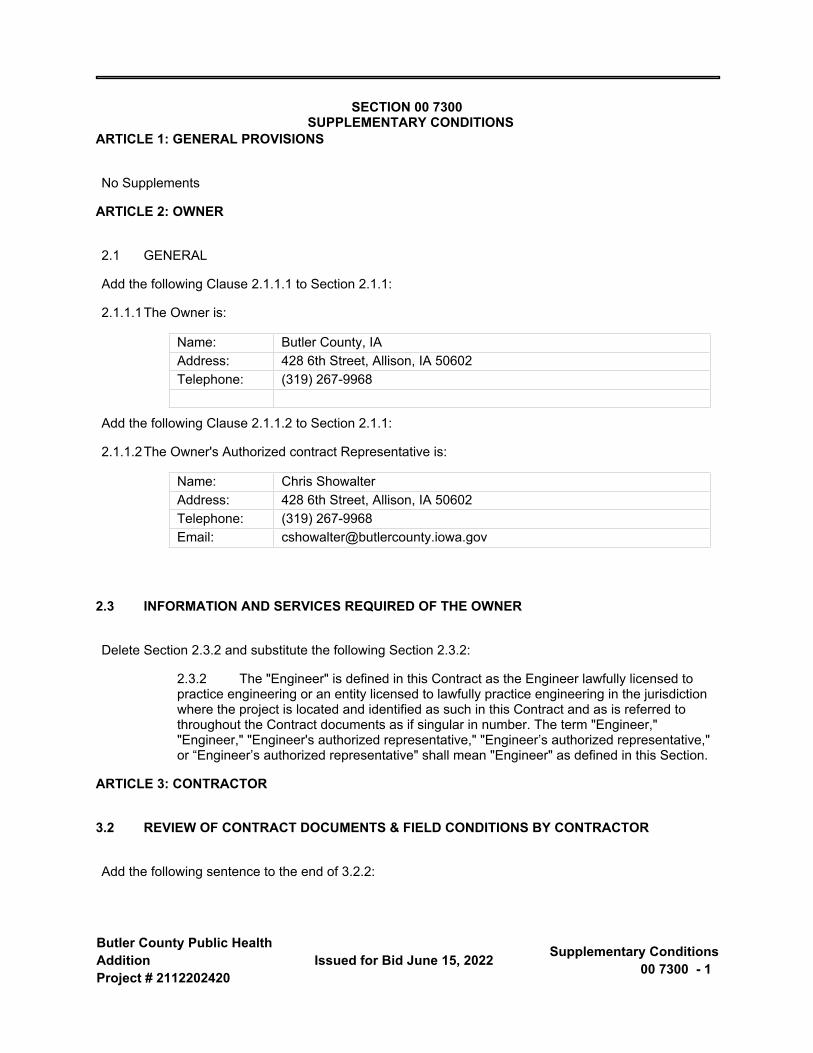
SECTION 00 7300 SUPPLEMENTARY CONDITIONS
ARTICLE 1: GENERAL PROVISIONS
No Supplements
ARTICLE 2: OWNER
2.1 GENERAL
Add the following Clause 2.1.1.1 to Section 2.1.1:
2.1.1.1The Owner is:
Name: Butler County, IA Address: 428 6th Street, Allison, IA 50602Telephone: (319) 267-9968
Add the following Clause 2.1.1.2 to Section 2.1.1:
2.1.1.2The Owner's Authorized contract Representative is:
Name: Chris ShowalterAddress: 428 6th Street, Allison, IA 50602Telephone: (319) 267-9968Email: [email protected]
2.3 INFORMATION AND SERVICES REQUIRED OF THE OWNER
Delete Section 2.3.2 and substitute the following Section 2.3.2:
2.3.2 The "Engineer" is defined in this Contract as the Engineer lawfully licensed to practice engineering or an entity licensed to lawfully practice engineering in the jurisdiction where the project is located and identified as such in this Contract and as is referred to throughout the Contract documents as if singular in number. The term "Engineer," "Engineer," "Engineer's authorized representative," "Engineer’s authorized representative," or “Engineer’s authorized representative" shall mean "Engineer" as defined in this Section.
ARTICLE 3: CONTRACTOR
3.2 REVIEW OF CONTRACT DOCUMENTS & FIELD CONDITIONS BY CONTRACTOR
Add the following sentence to the end of 3.2.2:
Butler County Public Health Addition Project # 2112202420
Supplementary Conditions 00 7300 - 2 Issued for Bid June 15, 2022
3.2.2 The Contractor also represents that all Contract Documents for the Project have been examined, including those intended for work of trades not normally performed by the Contractor's own forces, and that it has become thoroughly familiar with all conditions which may pertain to or affect the Work under the Contract.
3.3 SUPERVISION AND CONSTRUCTION PROCEDURES
Add the following Sections 3.3.4 and 3.3.5:
3.3.4 The Owner reserves the right to retain ownership to any materials or equipment that is part of the existing facility. If material or equipment is to be removed from the site, the Contractor shall detach such items and before removing from site, obtain permission from the Owner, or his designee, to do so. All items not retained by Owner shall be removed in a proper manner by the Contractor.
3.3.5 The Contractor shall submit to the Owner before construction begins one copy of Material Safety Data Sheets of hazardous substances to be stored on the Owner’s premises or incorporated in the performance of this contract. The Contractor shall also keep Material Safety Data Sheets posted at the work site for all substances while these substances are on the Owner’s premises. Hazardous substances shall be any substance which is covered by Law (Right to Know Rules).
3.4 LABOR AND MATERIALS
Add the following sentence to the end of 3.4.1:
3.4.1 Work required by the Contract Documents to be performed after working hours or work the Contractor elects to perform after hours shall be included in the Contract Sum.
Add Sections 3.4.4 through 3.4.8:
3.4.4 After the Contract has been executed, the Owner and the Engineer will consider a formal request for the substitution of products in place of those specified only under the conditions set forth in the Specifications, Division 01, General Requirements.
3.4.5 By making requests for substitutions based on Subparagraph 3.4.4 above, the Contractor:
1. Represents that the Contractor has personally investigated the proposed substitute product and determined that it is equal or superior in all respects to that specified;
2. Represents that the Contractor will provide the same warranty for the substitution that the Contractor would for the specified product;
3. Certifies that the cost data presented in the substitution request is complete and includes all related costs under this Contract except the Engineer's review and/or redesign costs, and waives all claims for additional costs related to the substitution which subsequently become apparent; and
4. Will coordinate the installation of the accepted substitute, making such changes as may be required for the Work to be complete in all respects at the Contractor's expense.
Butler County Public Health Addition Project # 2112202420
Issued for Bid June 15, 2022 Supplementary Conditions00 7300 - 3
3.4.6 The Owner shall be entitled to reimbursement from the Contractor for amounts paid to the Engineer for reviewing the Contractor's proposed substitutions and making agreed-upon changes in the Drawings and Specifications resulting from such substitutions.
3.4.7 The Owner shall be entitled to deduct from the Contract Sum amounts paid to the Engineer or Engineer's Consultants to evaluate the Contractor's proposed substitutions and to make agreed-upon changes in the Contract Documents made necessary by the Owner's acceptance of such substitutions.
3.4.8 The Contractor, and its subcontractors, shall conform to local labor laws of the State in which the project resides. Prior to starting Work, the Contractor shall become familiar with local labor and trade conditions, skilled and unskilled, and shall conform to the local conditions. The Contractor shall consider the availability of labor in the area and import labor as may be required, at the Contractor's expense, to meet the Schedule for the Work.
3.6 TAXES
Delete the language in Section 3.6 and substitute the following Sections:
3.6.1 This Project is exempt from State and local sales and use taxes on sales of building materials and fixtures to construction contractors for incorporation into real estate for governmental bodies of the State of Iowa. The Contractor shall continue to pay sales tax on items that do not become a part of the Project. For details, refer to .
3.6.2 The Owner as a designated exempt entity will complete an online application to register this Project with the Iowa Department of Revenue and Finance. The Owner will distribute Tax Exemption Certificates and Authorization Letters to the Contractor and all Subcontractors who have been identified at, or before filing of the Performance Bond.
3.6.3 On or before the time the Performance Bond is filed, the Contractor shall provide a listing to the Owner identifying all Subcontractors. Contractor and Subcontractors shall make copies of the Tax Exemption Certificate and provide a copy to each supplier providing construction material. This Certificate will allow the Contractor and Subcontractors to purchase qualified building materials free from sales tax for the Project. The Tax Exemption Certificate and Authorization Letter have been developed exclusively for this purpose and are applicable only for this specific Project.
3.6.4 If the online registration is not available at the time The Contract is approved by the Owner, the Owner will notify the Contractor, in writing, and the cost of sales tax on all construction materials used for the Project will be added to the Contract Sum. The Contractor shall then submit Form 35-002 to the Owner for Iowa sales/use tax paid.
3.6.5 Payment will be made in accordance with the payment provisions set out in these specifications and the Advertisement for Bids and Notice of Public Hearing. Notwithstanding anything in these specifications and the Advertisement for Bides and Notice of Public Hearing to the contrary, no Final Payment shall be released until Form 35-002 has been filed with the Owner, where applicable, and all lien waivers are on file.
3.6.6 Notwithstanding anything herein to the contrary, Contractor shall file with Owner forms contemplated by the Iowa Code enabling Owner to apply for a refund for any sales or use tax paid in carrying out the work.
3.7 PERMITS, FEES, NOTICES, AND COMPLIANCE WITH LAWS
Butler County Public Health Addition Project # 2112202420
Supplementary Conditions 00 7300 - 4 Issued for Bid June 15, 2022
Delete Section 3.7.5 and substitute the following Section 3.7.5:
3.7.5 If, in the course of the Work, the Contractor knowingly encounters and recognizes human remains, burial markers, archeological sites or wetlands not indicated in the Contract Documents, the Contractor shall immediately suspend any operations that would affect them and shall notify the Owner and Engineer. Upon receipt of such notice, the Owner shall promptly take any action necessary to obtain governmental authorization required to resume the operations. The Contractor shall continue to suspend such operations until otherwise instructed by the Owner but shall continue with all other operations that do not affect those remains and features. Requests for adjustments in the Contract Sum and Contract Time arising from the existence or good faith belief of such existence of such remains or features may be made as provided in Article 15.
Add Clauses 3.7.5.1 through 3.7.5.3 to Section 3.7.5:
3.7.5.1 Upon securing building permits, any plan reviews and fees which may be required by the State or Local Jurisdiction Having Authority in which the project resides, such as Fire Alarm and Automatic Sprinkler System, shall be borne by the Contractor.
3.7.5.2 The Contractor is responsible for scheduling inspections related to the performance of its Work and ensuring Work is complete for inspections. The Contractor is responsible for any costs associated with re-inspection caused by Work that is not in accordance with the requirements of the Contract Documents. In addition, the Contractor is responsible for costs associated with Engineering services related to evaluation of the deficiencies and development of an acceptable solution.
3.7.5.3 The Owner shall be entitled to deduct from the Contract Sum amounts paid to the Engineer or Engineer's Consultants for services related to evaluation of the deficiencies and development of an acceptable solution, including agreed-upon changes in the Contract Documents.
Add the following Section 3.7.6 and associated clauses 3.7.6.1 thru 3.7.6.3:
3.7.6 The State of Iowa, its agencies, and its political subdivisions, including cities, school districts, public partnerships, and public utilities are required by Iowa Code Section 73A.21 to require a reciprocal resident bidder and resident labor force preference.
3.7.6.1 A “Resident Bidder” means a person or entity authorized to transact business in the State of Iowa and having a place of business for transacting business within the state at which it is conducting and has conducted business for at least three years prior to the date of the first advertisement for the public improvement. If another state or foreign country has a more stringent definition of a resident bidder, the more stringent definition is applicable as to bidders from that state or foreign country.
3.7.6.2 A resident bidder shall be allowed a preference as against a nonresident bidder from a state or foreign country other than Iowa if that state our foreign country gives or requires any preference to bidders from that state of foreign country, including but not limited to any preference to bidders, the imposition of any type of labor force preference, or any other form of preferential treatment to bidders or laborers from that state of foreign county. The preference allowed shall be equal to the preference given or required by the state or foreign country in which the nonresident bidder is a resident.
Butler County Public Health Addition Project # 2112202420
Issued for Bid June 15, 2022 Supplementary Conditions00 7300 - 5
3.7.6.3 If the Contractor is a nonresident bidder, the Contractor is required to specify in the Agreement between the Owner and Contractor whether any preference (as described in 3.7.6.2) is in effect in the nonresident bidder’s state or country at the time of this bid and identify the source of the regulation.
3.9 SUPERINTENDENT
Delete Section 3.9.1 and substitute the following Section 3.9.1:
3.9.1 The Contractor shall employ a competent superintendent and necessary assistants who shall be in attendance at the Project site whenever two or more subcontractors are performing the Work. The superintendent’s absence from the project site when work is being performed does not relieve the Contractor of any responsibility for correctly performing the Work. The superintendent shall represent the Contractor, and communications given to the superintendent shall be as binding as if given to the Contractor.
3.10 CONTRACTOR’S CONSTRUCTION AND SUBMITTAL SCHEDULE
Delete the last sentence of Section 3.10.2 so that the Section now reads:
3.10.2 The Contractor promptly after being awarded the Contract and thereafter as necessary to maintain a current submittal schedule, shall submit a submittal schedule for the Engineer’s approval. The Engineer's approval shall not be unreasonably delayed or withheld. The submittal schedule shall (1) be coordinated with the Contractor’s construction schedule, and (2) allow the Engineer reasonable time to review submittals.
3.12 SHOP DRAWINGS, PRODUCT DATA AND SAMPLES
Add the following Section 3.12.11:
3.12.11 The Engineer's and its Consultants' review of Contractor's submittals will be limited to examination of an initial submittal and one (1) re-submittal. The Engineer's review of additional submittals will be made only with the consent of the Owner after written notification to the Contractor and Owner by the Engineer. The Owner shall be entitled to deduct from the Contract Sum amounts paid to the Engineer for evaluation of such additional re-submittals.
3.13 USE OF SITE
Add the following Sections 3.13.1 and 3.13.2:
3.13.1 Contractor shall perform the Work so as to cause a minimum of inconvenience to and interruption of the Owner's operations. Any and all interruptions of the operations of the Owner necessary for the performance of the Work shall be noted in the Progress Schedule and the Contractor shall additionally give the Owner sufficient advanced written notice of such interruption as to allow the Owner to adjust operations accordingly. Contractor's failure to give the Owner timely written notice of such intentions shall place the responsibility of any resulting delays or additional costs solely with the Contractor.
Butler County Public Health Addition Project # 2112202420
Supplementary Conditions 00 7300 - 6 Issued for Bid June 15, 2022
3.13.2 The Contractor, any subcontractor, supplier, vendor or anyone else for whom the Contractor is responsible, shall not bring on the site any asbestos, PCB's, petroleum, hazardous waste or radioactive materials, except for proper use in performing the Work.
3.14 CUTTING AND PATCHING
Delete Section 3.14.1 and replace with the following:
3.14.1 The Contractor shall be responsible for cutting, fitting or patching required to complete the Work or to make its parts fit together properly. Contractor shall be responsible for cutting and patching not specifically indicated on the drawings, but required for completion of their Work. No structural member shall be cut unless approved by the Engineer or Engineer's Consultants. All areas requiring cutting, fitting, or patching shall be restored to the condition existing prior to the cutting, fitting, or patching, unless otherwise required by the Contract Documents.
ARTICLE 4: ENGINEER
4.1 GENERAL
Add the following clause 4.1.1.1 to section 4.1.1:
4.1.1.1The Engineer is:
Name: Shive-Hattery, Inc.Address: 222 Third Ave. SE, Suite 300Phone: 319-364-0227Project Contact Person: Matt GordonContact Person Email: [email protected]
4.2 ADMINISTRATION OF THE CONTRACT
Add Clause 4.2.2.1 to Section 4.2.2:
4.2.2.1 The Owner is entitled to reimbursement from the Contractor for amounts paid the Engineer for site visits made necessary by the fault of the Contractor or by defects and deficiencies in the Work. The Owner shall be entitled to deduct from the Contract Sum amounts paid to the Engineer for such site visits.
Add the following sentence to the end of Section 4.2.13:
4.2.13 The term aesthetic effect includes, but is not limited to color, texture, profile, and relationship of masses.
ARTICLE 5: SUBCONTRACTORS
5.2 AWARD OF SUBCONTRACTS AND OTHER CONTRACTS FOR PORTIONS OF THE WORK
Delete Section 5.2.1 and substitute with the following Section 5.2.1:
Butler County Public Health Addition Project # 2112202420
Issued for Bid June 15, 2022 Supplementary Conditions00 7300 - 7
5.2.1 Unless otherwise stated in the Contract Documents, the Contractor, within seven (7) calendar days after award of the contract and prior to execution of the contract, shall notify the Owner and Engineer of the persons or entities (proposed for each principal portion of the work including those who are to furnish materials or equipment fabricated to a special design). After receipt of the information the Engineer may notify the contractor within seven (7) calendar days whether or not the Owner or the Engineer, after due investigation, (1) has reasonable objection to any such proposed person or entity, or (2) requires additional time and/or information to complete the review. Failure of the Engineer to reply within this time period shall constitute notice of no reasonable objections.
ARTICLE 6: CONSTRUCTION BY OWNER OR BY SEPARATE CONTRACTORS
No Supplements
ARTICLE 7: CHANGES IN THE WORK
7.1 GENERAL
Add the following Section 7.1.4 and associated clauses 7.1.4.1 thru 7.1.4.9:
7.1.4 The combined overhead and profit included in the total cost to the Owner of a change in the Work shall be based on the following schedule:
7.1.4.1 For the Contractor, for Work performed by the Contractor's own forces, 15 percent of the cost.
7.1.4.2 For the Contractor, for Work performed by the Contractor's Subcontractors, 5 percent of the amount due the Subcontractors.
7.1.4.3 For each Subcontractor involved, for Work performed by that Subcontractor's own forces, 15 percent of the cost.
7.1.4.4 For each Subcontractor involved, for Work performed by the Subcontractor's Sub-subcontractors, 5 percent of the amount due the Sub-subcontractor.
7.1.4.5 The maximum allowable combined overhead and profit passed through to the Owner under any circumstances shall be a maximum of 25 percent.
7.1.4.6 Cost to which overhead and profit is to be applied shall be determined in accordance with Section 7.3.4.
7.1.4.7 In order to facilitate checking of quotations for extras or credits, all proposals, except those so minor that their property can be seen by inspection, shall be accompanied by a complete itemization of costs including labor, materials, and subcontracts. Itemize labor by trade, tasks, hour quantities and labor rates. Itemize materials by product, quantity and unit price. Where major cost items are subcontracts, they shall be itemized also. In no case will a change involving over $500 be approved without such itemization.
7.1.4.8 The Contractor represents that proposals will include all related costs prior to presentation to the Owner or Engineer for consideration.
Butler County Public Health Addition Project # 2112202420
Supplementary Conditions 00 7300 - 8 Issued for Bid June 15, 2022
7.1.4.9 The Engineer's review of the Contractor's proposals will be limited to one initial submittal and one re-submittal. The Owner is entitled to obtain reimbursement from the Contractor for amounts paid to the Engineer for evaluation and response to additional re-submittals, wherein the first two submittals were not prepared in accordance with the Contract Documents.
7.2 CHANGE ORDERS
Add the following Section 7.2.2:
7.2.2 The forms used to process a Change Order will include AIA Document AIA G701, Change Order.
ARTICLE 8: TIME
8.1 DEFINITIONS
Delete Section 8.1.4 and substitute the following Section 8.1.4:
8.1.4 The term "Day" as used in the Contract Documents shall mean working day, excluding weekends and legal holidays.
8.2 PROGRESS AND COMPLETION
8.2.2 Delete the word "knowingly" in the first sentence.
8.2.3 Revise the end of the sentence after "Substantial Completion" as follows:
"...and Final Completion within the Contract Times specified."
ARTICLE 9: PAYMENTS AND COMPLETION
9.3 APPLICATION FOR PAYMENT
Delete Section 9.3.1 and substitute the following Section 9.3.1:
(For governmental bodies in Iowa, including the State, Counties, Cities, School Districts, etc.)
9.3.1 At least 30 (thirty) days before the date established for each progress payment, the Contractor shall submit to the Engineer an itemized Application for Payment for operations completed in accordance with the schedule of values. The application shall be notarized, if required, and supported by all data substantiating the Contractor’s right to payment that the Owner or Engineer require, such as copies of requisitions, and releases and waivers of liens from Subcontractors and suppliers. If the Contract Documents require the Owner to retain a portion of the payments until some future time, the Applications for Payment shall clearly state the percentage and the amount to be retained. The
Butler County Public Health Addition Project # 2112202420
Issued for Bid June 15, 2022 Supplementary Conditions00 7300 - 9
form of Application for Payment shall be a notarized current edition of AIA Document AIA G702 , Application and Certification for Payment, supported by current edition of AIA Document AIA G703, Continuation Sheet.
9.3.1.3 Until Substantial Completion, the Owner shall pay 95 percent of the amount due the Contractor on account of progress payments.
9.5 DECISIONS TO WITHHOLD CERTIFICATION
Delete Section 9.5.4 in its entirety.
9.6 PROGRESS PAYMENTS
Delete Section 9.6.1 and substitute the following Section 9.6.1:
9.6.1 After the Engineer has issued a Certificate for Payment and the Owner has approved the Application for Payment the Owner shall make payment in the manner provided in the contract Documents and in accordance with Iowa Code Chapters 26 and 573, latest edition.
Delete the first two sentences of Section 9.6.4 so that it reads as follows:
9.6.4 Neither the Owner nor Engineer shall have an obligation to pay, or to see to the payment of money to, a Subcontractor or supplier, except as may otherwise be required by law.
9.8 SUBSTANTIAL COMPLETION
Delete Section 9.8.1 and substitute the following Section 9.8.1:
9.8.1 Substantial Completion is the stage in the progress of the Work as being when any of the following occurs:
1) Completion of the public improvement project or the highway, bridge, or culvert project or when the work on the public improvement or the highway, bridge, or culvert project has been substantially completed in general accordance with the terms and provisions of the contract.
2) The work on the public improvement or on the designated portion is substantially completed in general accordance with the terms of the contract so that the governmental entity or the department can occupy or utilize the public improvements or designated portion of the public improvement for its intended purpose. This subparagraph shall not apply to highway, bridge, or culvert projects.
3) The public improvement project or the highway, bridge, or culvert project is certified as having been substantially completed by either of the following:
(a) The Engineer authorized to make such certification.(b) The authorized contract representative.
Butler County Public Health Addition Project # 2112202420
Supplementary Conditions 00 7300 - 10 Issued for Bid June 15, 2022
4) The governmental entity or the department is occupying or utilizing the public improvement for its intended purpose. This subparagraph shall not apply to highway, bridge, or culvert projects.
9.10 FINAL COMPLETION AND FINAL PAYMENT
Add the following Clause 9.10.1.1 to Section 9.10.1:
9.10.1.1 The Engineer will perform no more than two inspections to determine whether the Work or a designated portion thereof has attained Final Completion in accordance with the Contract Documents. The Owner is entitled to reimbursement from the Contractor for the amounts paid to the Engineer for any additional inspections.
Delete Section 9.10.2 and substitute the following Section:
9.10.2 Neither final payment nor any remaining retained percentage shall become due until the Contractor submits to the Engineer (1) an affidavit that payrolls, bills for materials and equipment, and other indebtedness connected with the Work for which the Owner or the Owner’s property might be responsible or encumbered (less amounts withheld by Owner) have been paid or otherwise satisfied, (2) a certificate evidencing that insurance required by the Contract Documents to remain in force after final payment is currently in effect. (3) a written statement that the Contractor knows of no substantial reason that the insurance will not be renewable to cover the period required by the Contract Documents, (4) consent of surety, if any, to final payment and (5), if required by the Owner, other data establishing payment or satisfaction of obligations, such as receipts, releases and waivers of liens, claims, security interests or encumbrances arising out of the Contract, to the extent and in such form as may be designated by the Owner. If a Subcontractor refuses to furnish a release or waiver required by the Owner, the Contractor may furnish a bond satisfactory to the Owner to indemnify the Owner against such lien. If such lien remains unsatisfied after payments are made, the Contractor shall refund to the Owner all money that the Owner may be compelled to pay in discharging such lien, including all costs and reasonable attorneys’ fees.
Add the following Section 9.10.6:
9.10.6 Final payment will be made no less than thirty (30) days after the date of acceptance of the Work by the Owner subject to the provisions of Sections 9.10.1 through 9.10.5. The following documents shall be completed by the contract completion date listed on the Form of Agreement and shall be received prior to making final payment:
1) Building Permit(s)
2) Certificate of Occupancy
3) Affidavits
4) Warranties
5) Lien Waivers
6) Record Drawings
7) Operation & Maintenance manuals
Butler County Public Health Addition Project # 2112202420
Issued for Bid June 15, 2022 Supplementary Conditions00 7300 - 11
Add the following Section 9.10.7 and Clauses 9.10.7.1 thru 9.10.7.4:
9.10.7 The following clauses are in accordance with Iowa Code, Chapter 26, Section 26.13, Early Release of Retainage, and are reiterated here for reference. Other provisions of Chapter 26, Chapter 573, and other applicable Chapters of the Code also apply:
9.10.7.1 At any time after all work on the project is substantially completed, the Contractor may request the release of all or part of the retained funds owed. The request shall be accompanied by a sworn statement of the Contractor that, ten (10) calendar days prior to filing the request, notice was given as required by Section 7 (of Chapter 26) to all known subcontractors, sub-subcontractors and suppliers.
9.10.7.2 Except as provided under Section 3 (of Chapter 26), upon receipt of such request, the Owner shall release all or part of the retained funds. Retained funds that are approved as payable shall be paid at the time of the next monthly payment or within 30 days, whichever is sooner. If partial retained funds are released pursuant to a Contractor’s request, no retained funds shall be subsequently held based on that portion of the work. If within 30 days of when payment becomes due the Owner does not release the retained funds due, interest shall accrue on the amount of retained funds at the rate of interest that is calculated as the prime rate plus one percent per year as of the day interest begins to accrue until the amount is paid.
9.10.7.3 If labor and/or materials are yet to be provided at the time the request for the release of the retained funds is made, an amount equal to 200% of the value of the labor and/or materials yet to be provided, as determined by the Owner, may be withheld until such labor and/or materials are provided.
9.10.7.4 An itemization of the labor and/or materials yet to be provided, or the reason that the request of retained funds is denied, shall be provided to the Contractor within 30 calendar days of the receipt for release of retained funds.
ARTICLE 10: PROTECTION OF PERSONS AND PROPERTY
10.2 SAFETY OF PERSONS AND PROPERTY
Delete Section 10.2.2 and substitute the following Section 10.2.2:
10.2.2 The Contractor shall give notices and comply with applicable laws, ordinances, regulations and lawful orders of public authorities bearing safety of persons or property or their protection from damage, injury or loss. This requirement also includes compliance with Iowa’s Smoke Free Air Act and Iowa’s Sex Offender law which no longer allows registered sex offenders to be on school property without the school’s permission. Refer to the Acknowledgment and Certification document 00 7300.01 that all Contractors, Subcontractors, and Vendors must sign.
Delete Section 10.2.4 and substitute the following Section 10.2.4:
10.2.4 When use, handling, and/or storage of explosives or other hazardous materials or equipment or unusual methods is necessary for execution of the work, the Contractor shall give the Owner reasonable advance notice and shall exercise utmost care and carry on such activities under the supervision of properly qualified personnel.
Butler County Public Health Addition Project # 2112202420
Supplementary Conditions 00 7300 - 12 Issued for Bid June 15, 2022
ARTICLE 11: INSURANCE AND BONDS
11.1 CONTRACTOR’S INSURANCE AND BONDS
Add the following paragraphs to Section 11.1.2
11.1.2.1 The Contractor shall deliver the required bonds to the Owner not later than ten days following the date the Agreement is entered into, or if the work is to be commenced prior thereto in response to a letter of intent, the Contractor shall, prior to commencement of the work, submit evidence satisfactory to the Owner that such bonds will be furnished.
11.1.2.2 The Contractor shall require the attorney-in-fact who executes the required bonds on behalf of the surety to affix thereto a certified and current copy of the power of attorney.
ARTICLE 12: UNCOVERING AND CORRECTION OF WORK
Add the following Clause 12.2.2.4 to Section 12.2.2:
12.2.2.4 Upon request by the Owner and prior to the expiration of one year from the date of Substantial Completion, the Engineer will conduct and the Contractor shall attend a meeting with the Owner to review the facility operations and performance.
ARTICLE 13: MISCELLANEOUS PROVISIONS
13.1 GOVERNING LAW
Delete the language in Section 13.1 and substitute the following language:
13.1 The Contract shall be governed by the law of the place where the Project is located.
13.6 EQUAL EMPLOYMENT OPPORTUNITY
Add the following subparagraphs to 13.6:
13.6.1 The Contractor shall conform in all respects with the provisions of the Federal Civil Rights Act, the Code of Iowa, Chapter 216 Civil Rights Commission and the rules and regulations adopted thereto by the Iowa Civil Rights Commission. The Contractor shall not discriminate against any employee or applicant because of race, color, religion, sex, national origin, sexual orientation, gender identity, ancestry, age, marital status, physical or mental handicap. The Contractor shall require similar clauses in all of its subcontracts for service or materials.
ADD THE FOLLOWING SECTION TO ARTICLE 13:
13.11 NICOTINE FREE ZONE
Butler County Public Health Addition Project # 2112202420
Issued for Bid June 15, 2022 Supplementary Conditions00 7300 - 13
Add the following subparagraph to 13.11:
13.11.1 Nicotine is not allowed on the Owner’s premises which includes personal or company vehicles parked on the Owner’s property.
ARTICLE 14: TERMINATION OR SUSPENSION OF THE CONTRACT
No Supplements
ARTICLE 15: CLAIMS AND DISPUTES
15.1 CLAIMS
Delete Section 15.1.2 in its entirety and substitute the following Section 15.1.2 and Clauses 15.1.2.1 thru 15.1.2.3:
15.1.2 Time Limits on Claims - As between the Owner and the Contractor, the commencement of the statutory limitation period shall be as follows:
15.1.2.1 Before Substantial Completion. As to acts or failures to act occurring prior to the relevant date of Substantial Completion, any applicable statute of limitations shall commence to run and any alleged cause of action shall be deemed to have accrued in any and all events not later than such date of Substantial Completion.
15.1.2.2 Between Substantial Completion and Final Certificate for Payment. As to acts or failures to act occurring subsequent to the relevant date of Substantial Completion and prior to issuance of the final Certificate for Payment, any applicable statute of limitations shall commence to run and any alleged cause of action shall be deemed to have accrued in any and all events not later than the date of issuance of the final Certificate for Payment.
15.1.2.3 After Final Certificate of Payment. As to acts or failures to act occurring after the relevant date of issuance of the final Certificate for Payment, any applicable statute of limitations shall commence to run and any alleged cause of action shall be deemed to have accrued in any and all events not later than the date of any act or failure to act by the Contractor pursuant to any Warranty provided under Section 3.5, the date of any correction of the Work or failure to correct the Work by the Contractor under Section 12.2, or the date of actual commission of any other act or failure to perform any duty or obligation by the Contractor or Owner, whichever occurs last.
Add Clauses 15.1.5.3 and 15.1.5.4 to Section 15.1.5:
15.1.5.3 Claims for increase in the Contract Time shall set forth in detail the circumstances that form the basis for the Claim, the date upon which each cause of delay began to affect the progress of the Work, the date upon which each cause of delay ceased to affect the progress of the Work and the number of days’ increase in the Contract Time claimed as a consequence of each such cause of delay. The Contractor shall provide such supporting documentation as the Owner may require including, where appropriate, a revised construction schedule indicating all the activities affected by the circumstances forming the basis of the Claim.
Butler County Public Health Addition Project # 2112202420
Supplementary Conditions 00 7300 - 14 Issued for Bid June 15, 2022
15.1.5.4 The Contractor shall not be entitled to a separate increase in the Contract Time for each one of the number of causes of delay which may have concurrent or interrelated effects on the progress of the Work, or for concurrent delays due to the fault of the Contractor.
END OF SECTION
Butler County Public Health AdditionProject # 2112202420
Issued for Bid June 15, 2022 Summary01 1000 - 1
SECTION 01 1000 SUMMARY
PART 1 GENERAL
1.1 PROJECT
A. Project Name: Butler County Public Health Addition
B. Engineer's Name: Shive-Hattery, Inc.
C. The Project consists of the construction of The project consists of 4256 sf addition and 1280 sf of garage area to the existing County Emergency Management Building to include exam rooms, office space, and medical support spaces for the Public Health Department.
1.2 CONTRACT DESCRIPTION
A. Contract Type: A single prime contract based on a Stipulated Price as described in Document 00 5200 - Agreement Form.
1.3 DESCRIPTION OF ALTERATIONS WORK
A. Scope of alterations work is indicated on drawings.
1.4 PROJECT SCHEDULE
A. The project schedule is defined in the Advertisement for Bids.
1.5 WORK UNDER OTHER CONTRACTS
A. General: Cooperate fully with separate contractors so work on those contracts may be carried out smoothly, without interfering with or delaying work under this Contract. Coordinate the Work of this Contract with work performed under separate contracts.
1.6 OWNER OCCUPANCY
A. Owner intends to occupy the Project upon Substantial Completion.
B. Cooperate with Owner to minimize conflict and to facilitate Owner's operations.
C. Schedule the Work to accommodate Owner occupancy.
1.7 CONTRACTOR USE OF SITE AND PREMISES
A. General: Contractor shall have full use of premises for construction operations, including use of Project site, during construction period. Each Contractor's use of premises is limited only by Owner's right to perform work or to retain other contractors on portions of Project.
B. Arrange use of site and premises to allow:
1. Owner occupancy. Allow for Owner occupancy of Project siteand use by the public.2. Work by Others.
C. Provide access to and from site as required by law and by Owner:
1. Emergency Building Exits During Construction: Keep all exits required by code open during construction period; provide temporary exit signs if exit routes are temporarily altered.
Butler County Public Health Addition Project # 2112202420
Summary 01 1000 - 2 Issued for Bid June 15, 2022
2. Do not obstruct roadways, sidewalks, or other public ways without permit.3. Driveways and Entrances: Keep driveways, parking garage, loading areas, and
entrances serving premises clear and available to Owner, Owner's employees, or emergency vehicles at all times. Do not use these areas for parking or storage of materials.
a. Schedule deliveries to minimize use of driveways and entrances.
b. Schedule deliveries to minimize space and time requirements for storage of materials and equipment on-site.
D. Existing building spaces may not be used for storage.
E. Use of Existing Building: Maintain existing building in a weathertight condition throughout construction period. Repair damage caused by construction operations. Protect building and its occupants during construction period.
F. Utility Outages and Shutdown:
1. Do not interrupt utilities serving facilities occupied by Owner or others unless permitted under the following conditions and then only after arranging to provide temporary utility services according to requirements indicated:
2. Limit disruption of utility services to hours the building is unoccupied.3. Do not disrupt or shut down life safety systems, including but not limited to fire sprinklers
and fire alarm system, without 7 days notice to Owner and authorities having jurisdiction.4. Prevent accidental disruption of utility services to other facilities.5. Do not proceed with utility interruptions without Owner's written permission.
END OF SECTION
Butler County Public Health AdditionProject # 2112202420
Issued for Bid June 15, 2022 Price and Payment Procedures01 2000 - 1
SECTION 01 2000 PRICE AND PAYMENT PROCEDURES
PART 1 GENERAL
1.1 SECTION INCLUDES
A. Procedures for preparation and submittal of applications for progress payments.
1.2 RELATED REQUIREMENTS
A. Section 00 5000 - Contracting Forms and Supplements: Forms to be used.
B. Section 00 7200 - General Conditions: Additional requirements for progress payments, final payment, changes in the Work.
C. Section 00 7300 - Supplementary Conditions: Percentage allowances for Contractor's overhead and profit.
1.3 DEFINITIONS
A. Schedule of Values: A statement furnished by Contractor allocating portions of the Contract Sum to various portions of the Work and used as the basis for reviewing Contractor's Applications for Payment.
1.4 SCHEDULE OF VALUES
A. Coordination: Coordinate preparation of the Schedule of Values with preparation of Contractor's Construction Schedule.
B. Correlate line items in the Schedule of Values with other required administrative forms and schedules, including the following:
1. Application for Payment forms with Continuation Sheets.2. Submittals Schedule.3. Contractor's Construction Schedule.
C. Form to be used: AIA Document G703 Continuation Sheets
D. Content: Use the Project Manual table of contents as a guide to establish line items for the Schedule of Values. Provide at least one line item for each Specification Section.
1. Identification: Include the following Project identification on the Schedule of Values:
a. Project name and location.
b. Name of Engineer.
c. Engineer's project number.
d. Contractor's name and address.
e. Date of submittal.
E. Electronic media printout including equivalent information will be considered in lieu of standard form specified; submit draft to Engineer for approval.
F. Forms filled out by hand will not be accepted.

Butler County Public Health Addition Project # 2112202420
Price and Payment Procedures 01 2000 - 2 Issued for Bid June 15, 2022
G. Submit Schedule of Values to Engineer at earliest possible date but no later than 7 days after date on the Notice of Award .
H. Format: Utilize the Table of Contents of this Project Manual. Identify each line item with number and title of the specification Section. Identify site mobilization. Provide at least one line item for each Specification Section. Arrange the Schedule of Values in tabular form with separate columns to indicate the following for each item listed:
1. Related Specification Section or Division.2. Description of the Work.3. Name of subcontractor.4. Name of manufacturer or fabricator.
1.5 APPLICATIONS FOR PROGRESS PAYMENTS
A. Payment Period: Submit at intervals stipulated in the Agreement.
B. Electronic media printout including equivalent information will be considered in lieu of standard form specified; submit sample to Engineer for approval.
C. Forms filled out by hand will not be accepted.
D. Execute certification by signature of authorized officer.
E. Submit one electronic copy of each Application for Payment.
END OF SECTION

Butler County Public Health AdditionProject # 2112202420
Issued for Bid June 15, 2022 Substitution Procedures01 2500 - 1
SECTION 01 2500 SUBSTITUTION PROCEDURES
PART 1 GENERAL
1.1 SECTION INCLUDES
A. Procedural requirements for proposed substitutions.
1.2 RELATED REQUIREMENTS
A. Section 00 2113 - Instructions to Bidders: Restrictions on timing of substitution requests.
B. Section 00 4325 - Substitution Request Form: Required form for substitution requests made prior to award of contract (During procurement).
C. Section 00 6325 - Substitution Request Form - During Construction: Required form for substitution requests made after award of contract (During construction).
D. Section 01 3000 - Administrative Requirements: Submittal procedures, coordination.
E. Section 01 6000 - Product Requirements: Fundamental product requirements, product options, delivery, storage, and handling.
1.3 DEFINITIONS
A. Substitutions: Changes from Contract Documents requirements proposed by Contractor to materials, products, assemblies, and equipment.
1. Substitutions for Cause: Proposed due to changed Project circumstances beyond Contractor's control.
a. Unavailability.
b. Regulatory changes.
2. Substitutions for Convenience: Proposed due to possibility of offering substantial advantage to the Project.
a. Substitution requests offering advantages solely to the Contractor will not be considered.
PART 2 PRODUCTS - NOT USED
PART 3 EXECUTION
3.1 GENERAL REQUIREMENTS
A. A Substitution Request for products, assemblies, materials, and equipment constitutes a representation that the submitter:
1. Has investigated proposed product and determined that it meets or exceeds the quality level of the specified product, equipment, assembly, or system.
2. Agrees to provide the same warranty for the substitution as for the specified product.
Butler County Public Health Addition Project # 2112202420
Substitution Procedures 01 2500 - 2 Issued for Bid June 15, 2022
3. Agrees to coordinate installation and make changes to other work that may be required for the work to be complete, with no additional cost to Owner.
4. Waives claims for additional costs or time extension that may subsequently become apparent.
5. Agrees to reimburse Owner and Engineer for review or redesign services associated with re-approval by authorities.
B. Document each request with complete data substantiating compliance of proposed substitution with Contract Documents. Burden of proof is on proposer.
C. Content: Include information necessary for tracking the status of each Substitution Request, and information necessary to provide an actionable response.
1. Forms indicated in the Project Manual are adequate for this purpose, and must be used.D. Limit each request to a single proposed substitution item.
1. Submit an electronic document, combining the request form with supporting data into single document.
3.2 SUBSTITUTION PROCEDURES DURING PROCUREMENT
A. Submittal Time Restrictions:
B. Submittal Form (before award of contract):
1. Submit substitution requests by completing the form in Section 00 4325; see this section for additional information and instructions. Use only this form; other forms of submission are unacceptable.
3.3 SUBSTITUTION PROCEDURES DURING CONSTRUCTION
A. Submittal Form (after award of contract):
1. Submit substitution requests by completing the form in Section 00 6325; see this section for additional information and instructions. Use only this form; other forms of submission are unacceptable.
B. Submit request for Substitution for Cause within 14 days of discovery of need for substitution, but not later than 14 days prior to time required for review and approval by Engineer, in order to stay on approved project schedule.
C. Submit request for Substitution for Convenience immediately upon discovery of its potential advantage to the project, but not later than 14 days prior to time required for review and approval by Enginee, in order to stay on approved project schedule.
1. In addition to meeting general documentation requirements, document how the requested substitution benefits the Owner through cost savings, time savings, greater energy conservation, or in other specific ways.
2. Document means of coordinating of substitution item with other portions of the work, including work by affected subcontractors.
3. Bear the costs engendered by proposed substitution of:
a. Owner's compensation to the Engineer for any required redesign, time spent processing and evaluating the request.
b. Other construction by Owner.
c. Other unanticipated project considerations.
Butler County Public Health Addition Project # 2112202420
Issued for Bid June 15, 2022 Substitution Procedures01 2500 - 3
D. Substitutions will not be considered under one or more of the following circumstances:
1. When they are indicated or implied on shop drawing or product data submittals, without having received prior approval.
2. Without a separate written request.3. When acceptance will require revisions to Contract Documents.
3.4 RESOLUTION
A. Engineer may request additional information and documentation prior to rendering a decision. Engineer will request information or documentation within 7 days of receipt of a request for substitution.
B. Engineer will notify Contractor in writing of decision to accept or reject request within 15 days of receipt of request, or 7 days of receipt of additional information or documentation, whichever is later.
3.5 ACCEPTANCE
A. Accepted substitutions change the work of the Project. They will be documented and incorporated into work of the project by Change Order, Construction Change Directive, or similar instruments provided for in the Conditions of the Contract.
3.6 CLOSEOUT ACTIVITIES
A. See Section 01 7800 - Closeout Submittals, for closeout submittals.
B. Include completed Substitution Request Forms as part of the Project record. Include both approved and rejected Requests.
END OF SECTION

Butler County Public Health AdditionProject # 2112202420
Issued for Bid June 15, 2022 Contract Modification
Procedures01 2600 - 1
SECTION 01 2600 CONTRACT MODIFICATION PROCEDURES
PART 1 GENERAL
1.1 SECTION INCLUDES
A. Minor Changes in the Work
B. Proposal Requests
C. Change Order Procedures
D. Construction Change Directive
1.2 SUMMARY
A. This Section specifies administrative and procedural requirements for handling and processing Contract modifications.
1.3 MINOR CHANGES IN THE WORK
A. Engineer will issue supplemental instructions authorizing Minor Changes in the Work, not involving adjustment to the Contract Sum or the Contract Time, as a Software-Generated "Instruction to Contractor".
1.4 PROPOSAL REQUESTS
A. Proposal Requests: Engineer will issue a detailed description of proposed changes in the Work that may require adjustment to the Contract Sum or the Contract Time. If necessary, the description will include supplemental or revised Drawings and Specifications.
1. Proposal Requests issued by Engineer are for information only. Do not consider them instructions either to stop work in progress or to execute the proposed change.
2. Within 20 days after receipt of Proposal Request, submit a quotation estimating cost adjustments to the Contract Sum and the Contract Time necessary to execute the change.
a. Include a list of quantities of products required or eliminated and unit costs, with total amount of purchases and credits to be made. If requested, furnish survey data to substantiate quantities.
b. Indicate applicable taxes, delivery charges, equipment rental, and amounts of trade discounts.
c. Include costs of labor and supervision directly attributable to the change.
d. Include an updated Contractor's Construction Schedule that indicates the effect of the change, including, but not limited to, changes in activity duration, start and finish times, and activity relationship. Use available total float before requesting an extension of the Contract Time.
B. Contractor-Initiated Proposals: If latent or unforeseen conditions require modifications to the Contract, Contractor may propose changes by submitting a request for a change to Engineer.
Butler County Public Health Addition Project # 2112202420
Contract Modification Procedures 01 2600 - 2
Issued for Bid June 15, 2022
1. Include a statement outlining reasons for the change and the effect of the change on the Work. Provide a complete description of the proposed change. Indicate the effect of the proposed change on the Contract Sum and the Contract Time.
2. Include a list of quantities of products required or eliminated and unit costs, with total amount of purchases and credits to be made. If requested, furnish survey data to substantiate quantities.
3. Indicate applicable taxes, delivery charges, equipment rental, and amounts of trade discounts.
4. Include costs of labor and supervision directly attributable to the change.5. Include an updated Contractor's Construction Schedule that indicates the effect of the
change, including, but not limited to, changes in activity duration, start and finish times, and activity relationship. Use available total float before requesting an extension of the Contract Time.
6. Comply with requirements in Division 01 Section 01 6000 "Product Requirements" if the proposed change requires substitution of one product or system for product or system specified.
7. Proposal Request Form: Use AIA Document G709 for Proposal Requests.C. Stipulated Sum/Price Change Order: Based on Proposal Request and Contractor's fixed price
quotation or Contractor's request for a Change Order as approved by Engineer.
D. Unit Price Change Order: For predetermined unit prices and quantities, the Change Order will be executed on a fixed unit price basis. For unit costs or quantities of units of work which are not predetermined, execute Work under a Construction Change Directive. Changes in Contract Sum/Price or Contract Time will be computed as specified for Time and Material Change Order.
E. Construction Change Directive: Engineer may issue a directive, on AIA Form G714 Construction Change Directive signed by the Owner, instructing the Contractor to proceed with a change in the Work, for subsequent inclusion in a Change Order. Document will describe changes in the Work, and designate method of determining any change in Contract Sum/Price or Contract Time. Promptly execute the change.
F. Time and Material Change Order: Submit itemized account and supporting data after completion of change, within time limits indicated in the Conditions of the Contract. Engineer will determine the change allowable in Contract Sum/Price and Contract Time as provided in the Contract Documents.
G. Maintain detailed records of work done on Time and Material basis. Provide full information required for evaluation of proposed changes, and to substantiate costs for changes in the Work.
H. Change Order Forms: AIA G701 Change Order.
I. Execution of Change Orders: Engineer will issue Change Orders for signatures of parties as provided in the Conditions of the Contract.
1.5 CHANGE ORDER PROCEDURES
A. On Owner's approval of a Proposal Request, Engineer will issue a Change Order for signatures of Owner and Contractor on AIA Document G701.
1.6 CONSTRUCTION CHANGE DIRECTIVE
Butler County Public Health Addition Project # 2112202420
Issued for Bid June 15, 2022 Contract Modification
Procedures01 2600 - 3
A. Construction Change Directive: Engineer may issue a Construction Change Directive on AIA Document G714. Construction Change Directive instructs Contractor to proceed with a change in the Work, for subsequent inclusion in a Change Order.
1. Construction Change Directive contains a complete description of change in the Work. It also designates method to be followed to determine change in the Contract Sum or the Contract Time.
B. Documentation: Maintain detailed records on a time and material basis of work required by the Work Change Directive.
PART 2 PRODUCTS (NOT USED)
PART 3 EXECUTION (NOT USED)
END OF SECTION 01 2600

Butler County Public Health AdditionProject # 2112202420
Issued for Bid June 15, 2022 Administrative Requirements01 3000 - 1
SECTION 01 3000 ADMINISTRATIVE REQUIREMENTS
PART 1 GENERAL
1.1 SECTION INCLUDES
A. General administrative requirements.
B. Electronic document submittal service.
C. Preconstruction meeting.
D. Pre-installation meeting.
E. Progress meetings.
F. Construction progress schedule.
G. Submittals for review, information, and project closeout.
H. Number of copies of submittals.
I. Requests for Interpretation (RFI) procedures.
J. Submittal procedures.
K. Administrative and supervisory personnel
L. Requests for information (RFI).
M. Engineer's Digital Data Files
1.2 RELATED REQUIREMENTS
A. Section 00 7200 - General Conditions: Dates for applications for payment.
B. Section 00 7300 - Supplementary Conditions: Duties of the Construction Manager.
C. Section 01 6000 - Product Requirements: General product requirements.
D. Section 01 7000 - Execution and Closeout Requirements: Additional coordination requirements.
E. Section 01 7800 - Closeout Submittals: Project record documents; operation and maintenance data; warranties and bonds.
1.3 REFERENCE STANDARDS
A. AIA G810 - Transmittal Letter 2001.
1.4 GENERAL ADMINISTRATIVE REQUIREMENTS
A. Comply with requirements of Section 01 7000 - Execution and Closeout Requirements for coordination of execution of administrative tasks with timing of construction activities.
B. Make the following types of submittals to Engineer:
1. Requests for Interpretation (RFI).2. Requests for substitution.3. Shop drawings, product data, and samples.
Butler County Public Health Addition Project # 2112202420
Administrative Requirements 01 3000 - 2 Issued for Bid June 15, 2022
4. Test and inspection reports.5. Design data.6. Manufacturer's instructions and field reports.7. Applications for payment and change order requests.8. Progress schedules.9. Coordination drawings.10. Correction Punch List and Final Correction Punch List for Substantial Completion.11. Closeout submittals.
1.5 DEFINITIONS
A. RFI: Request from Contractor seeking interpretation, information, or clarification of the Contract Documents.
B. Action Submittals: Written and graphic information that does require Enigneer's responsive action.
C. Informational Submittals: Written information that does not require Engineer's responsive action. Submittals may be rejected for not complying with requirements.
1.6 PROJECT COORDINATION
A. Each contractor shall participate in coordination requirements. Certain areas of responsibility will be assigned to a specific contractor.
B. Coordination (Single-Prime): Each contractor shall coordinate its construction operations with those of other contractors and entities to ensure efficient and orderly installation of each part of the Work. Coordinate operations with operations included in different Sections, that depend on each other for proper installation, connection, and operation.
1. Schedule construction operations in sequence required to obtain the best results where installation of one part of the Work depends on installation of other components, before or after its own installation.
2. Coordinate installation of different components with other contractors to ensure maximum accessibility for required maintenance, service, and repair.
3. Make adequate provisions to accommodate items scheduled for later installation.4. Where availability of space is limited, coordinate installation of different components to
ensure maximum performance and accessibility for required maintenance, service, and repair of all components, including mechanical and electrical.
5. In finished areasexcept as otherwise indicated, conceal pipes, ducts, and wiring within the construction. Coordinate locations of fixtures and outlets with finish elements.
C. Prepare memoranda for distribution to each party involved, outlining special procedures required for coordination. Include such items as required notices, reports, and list of attendees at meetings.
1. Prepare similar memoranda for Owner and separate contractors if coordination of their Work is required.
D. Administrative Procedures: Coordinate scheduling and timing of required administrative procedures with other construction activities and activities of other contractors to avoid conflicts and to ensure orderly progress of the Work. Such administrative activities include, but are not limited to, the following:
Butler County Public Health Addition Project # 2112202420
Issued for Bid June 15, 2022 Administrative Requirements01 3000 - 3
1. Preparation of Contractor's Construction Schedule.2. Preparation of the Schedule of Values.3. Installation and removal of temporary facilities and controls.4. Delivery and processing of submittals.5. Progress meetings.6. Preinstallation conferences.7. Project closeout activities.
E. Conservation: Coordinate construction activities to ensure that operations are carried out with consideration given to conservation of energy, water, and materials.
1. Salvage materials and equipment involved in performance of, but not actually incorporated into, the Work. Refer to other Sections for disposition of salvaged materials that are designated as Owner's property.
1.7 ADMINISTRATIVE AND SUPERVISORY PERSONNEL
A. General: In addition to Project superintendent, provide other administrative and supervisory personnel as required for proper performance of the Work.
B. Key Personnel Names: Within 15 days of starting construction operations, submit a list of key personnel assignments, including superintendent and other personnel in attendance at Project site. Identify individuals and their duties and responsibilities; list addresses, email addresses, and telephone numbers, including home, mobile, and office telephone numbers. Provide names, addresses, and telephone numbers of individuals assigned as standbys in the absence of individuals assigned to Project.
1.8 PROJECT MEETINGS
A. General: Schedule and conduct meetings and conferences at Project site, unless otherwise indicated.
B. Attendees: Inform participants and others involved, and individuals whose presence is required, of date and time of each meeting. Notify Owner and Engine of scheduled meeting dates and times.
C. Agenda: Prepare the meeting agenda. Distribute the agenda to all invited attendees.
D. Minutes: Record significant discussions and agreements achieved. Distribute the meeting minutes to everyone concerned, including Owner and Engineer, within three days of the meeting.
1.9 REQUESTS FOR INFORMATION (RFI)
A. Procedure: Immediately on discovery of the need for information or interpretation of the Contract Documents, prepare and submit a Request for Information (RFI) in the form specified, with a necessary question regarding ambiguities or conflicts in the documents or field conditions, concealed conditions at the site, clarification of a contract requirement, dimensions, or other information for which clarification is required.
1. RFI's shall originate with Contractor, Engineer, or Owner. RFIs submitted by entities other than Contractor, Engineer, or Owner will be returned with no response.
2. Coordinate and submit RFIs in a prompt manner so as to avoid delays in Contractor's work or work of subcontractors.
Butler County Public Health Addition Project # 2112202420
Administrative Requirements 01 3000 - 4 Issued for Bid June 15, 2022
3. The Contractor is required to review all RFI's submitted by subcontractor's and suppliers for completeness, accuracy, validity, and justification prior to submission to the Engineer. The Contractor can commonly answer subcontractor /supplier RFI's without delegation to the Engineer.
4. Promptly submit any RFI's that could result in a delay of the activities on the critical path if the resolution is not obtained promptly. Provide a date on each RFI that the response is required by, in order to not have an impact on the critical path of construction activities.
5. In the case of a condition that requires a change in the work to resolve a conflict or other condition, the Contractor shall include a recommendation for resolution of the condition and submit a separate Change Order Request (COR).
6. The Engineer's response to an RFI is not an authorization to proceed with work involving additional cost, time or both. If the response involves additional work the Contractor shall provide the Engineer with a complete description of work added and work deleted by the response within seven (7) days of the issued date of the RFI response. If the response involves additional work for which the Contractor will seek an adjustment to the contract sum, time or both, the Contractor shall submit a cost proposal in the form of a Change Order Request (COR) to the Engineer. The Contractor shall not proceed with incorporating the response into the work until a Change Order or, Construction Change Directive has been fully executed.
7. Unless notified otherwise by the Contractor, the Engineer's RFI response shall have the same effect as the Engineer's order for minor changes in the Work. The Contractor will proceed with the Work, and the response will be incorporated into the contract that same as the Engineer's written order for minor changes in the Work. Notify the Engineer in writing if noted modifications cannot be made due to conflicting circumstances in the field, in other contract documents, or for other reasons.
8. The Contractor shall not incorporate any language into RFI’s or Change Proposals that imply future additional costs or delays beyond those fully explained within the document. The Contractor may stipulate conditions or constraints under which the pricing or time may change; however, such conditions or constraints shall not infringe on the Engineer’s or Owner’s right to adequate time for review of the issue.
9. The Contractor shall not submit Confirming RFI's, i.e., RFI's requesting confirmation of information already in the contract documents or previously provided, or requesting confirmation to questions previously answered or clarification previously given. Similarly the Contractor shall not submit Repetitive RFI's, i.e., RFI's, wherein the same information is requested more than once, even if phrased in another format or asked in a different manner. Confirming& Repetitive RFI's are considered frivolous.
10. The Contractor shall not retain or suppress RFI's for group submissions. Each individual RFI is to be submitted expeditiously upon occurrence. Numerous RFI's submitted in a short time period will not be considered reasonable, and will result in review times being extended accordingly.
11. The Contractor shall not install any components in locations other than as indicated on the contract documents unless 1) all other affected work has been reviewed and coordinated with the relocation; and 2) the relocation is the resolution for an RFI, including a statement by the Contractor that the relocation has been coordinated with other affected work.
12. The Contractor shall not use an RFI as a means of proposing a deviation, an alternative product, arrangement, or installation for the Contractor's convenience; these proposals shall be submitted as Substitution Requests, and the RFI voided. A contractor-proposed
Butler County Public Health Addition Project # 2112202420
Issued for Bid June 15, 2022 Administrative Requirements01 3000 - 5
alternative arrangement or installation submitted as an RFI will not become the subsequent basis for a claim by the contractor.
13. The Owner is entitled to reimbursement from the Contractor for amounts paid to the Engineer for evaluating and responding to:
a. Incomplete, illegitimate, or frivolous Contractor's requests for information and requests for information that are not prepared in accordance with the Contract Documents.
b. Contractor requests for information where the requested information is available to the Contractor from a careful study and comparison of the contract documents, field conditions, contractor-prepared coordination drawings, other Owner/Engineer-provided information or prior project correspondence or documentation.
c. Contractor-proposed alternative arrangements or installations for the convenience of the contractor which, upon acceptance, requires the Engineer to revise the contract documents.
B. Content of the RFI: Include a detailed, legible description of item needing interpretation and the following:
1. Project name.2. Date.3. Name of Contractor.4. Name of Engineer.5. RFI number, numbered sequentially.6. Specification Section number and title and related paragraphs, as appropriate.7. Drawing number and detail references, as appropriate.8. Field dimensions and conditions, as appropriate.9. Contractor's suggested solution(s). If Contractor's solution(s) impact the Contract Time or
the Contract Sum, Contractor shall state impact in the RFI.10. Contractor's signature or review stamp.11. Attachments: Include drawings, descriptions, measurements, photos, Product Data,
Shop Drawings, and other information necessary to fully describe items needing information or interpretation. Each RFI shall include sufficient detail for evaluation.
a. Supplementary drawings prepared by Contractor shall include dimensions, thicknesses, structural grid references, and details of affected materials, assemblies, and attachments.
C. Software-Generated RFI's: Software-generated form with substantially the same content as indicated above.
D. Engineer Action: Engineer will review each RFI, determine action required, and return it. Allow an average of ten working days for Engineer's response for each RFI. RFI's received after 1:00 p.m. will be considered as received the following working day. Some issues may take longer for review, the recipient of the RFI shall notify the sender of the RFI if additional time is required.
1. The following RFI's will be returned without action:
a. Requests for approval of submittals.
Butler County Public Health Addition Project # 2112202420
Administrative Requirements 01 3000 - 6 Issued for Bid June 15, 2022
b. Requests for approval of substitutions or deviations.
c. Requests for coordination information already indicated in the Contract Documents.
d. Requests for adjustments in the Contract Time or the Contract Sum.
e. Requests for interpretation of Engineer's actions on submittals.
f. Incomplete, inaccurate, invalid, and unjustified RFI's or RFI's with numerous errors.
g. Confirming or Repetitive RFI's.
2. Engineer's action may include a request for additional information, in which case Engineer's time for response will start again.
3. Engineer's action on RFI's that may result in a change to the Contract Time or the Contract Sum may be eligible for Contractor to submit a Change Proposal according to Division 01 Section "Contract Modification Procedures."
a. If the Contractor believes the RFI response warrants change in the Contract Time or the Contract Sum, notify Engineer in writing within seven days of receipt of the RFI response.
E. RFI Log: RFI Log will be maintained on the Newforma Info Exchange Site provided by the Engineer. The software/site will be used to generate, transmit, log, and receive RFIs and RFI responses on the project. The RFI Log can be exported from the site and used to communicate with other project team members. Software log with not less than the following:
1. Project name.2. Name and address of Contractor.3. Name and address of Engineer.4. RFI number including RFIs that were dropped and not submitted.5. RFI description.6. Date the RFI was submitted.7. Date Engineer response was received.8. Identification of related Minor Change in the Work, Construction Change Directive, and
Proposal Request, as appropriate.9. Identification of related Field Order, Work Change Directive, and Proposal Request, as
appropriate.
1.10 ENGINEER’S DIGITAL DATA FILES
A. General: The Engineer will provide digital data files of the contract drawings to the Contractor for use in preparing submittals.
1. The Engineer makes no representations as to the accuracy or completeness of digital data files as they relate to the Contract Drawings.
2. The digital data files are available in Revit 2021, AutoCAD 2018, or PDF.3. Contractor shall execute a digital data licensing agreement in the form of AIA Document
C106.4. The digital data files will be transmitted to the contractor via Newforma Info Exchange
Server. By downloading these documents, the Contractor agrees to also accept the following terms and conditions:
Butler County Public Health Addition Project # 2112202420
Issued for Bid June 15, 2022 Administrative Requirements01 3000 - 7
a. Definitions: “S-H” shall mean Shive-Hattery, Inc., Shive-Hattery A/E Services, P.C., or Design Organization, a Division of Shive-Hattery, Inc. “Client” shall mean the person or entity that has executed an Agreement with S-H for services resulting in this electronic file. “Other Party” shall mean any person or entity other than S-H or Client.
b. Where these electronic files are provided under the terms and conditions of a contract and such contract terms and conditions conflict with these terms and conditions, then the contract terms and conditions shall prevail.
c. In the event these electronic files are provided as a project deliverable to a Client of S-H:
1) The electronic files are submitted to the Client for a 30-day Acceptance Period.During this period, the Client may review and examine these files; any
errors detected during this time will be corrected by S-H as part of the basic agreement. Any changes requested after the Acceptance Period will be considered additional services to be performed on a time and material basis at S-H’s current standard fee schedule.
2) Because data stored on electronic media can deteriorate undetected or can be modified without S-H’s knowledge, the Client agrees that S-H will not be held liable for the completeness or correctness of the electronic media after an acceptance period of 30 days after delivery of the electronic files.
d. Any use or reuse of original or altered electronic files by the Client or Other Party without written verification, or CAD adaptation for the specific purpose intended by S-H, will be at the Client’s or Other Party’s risk and full legal responsibility. Furthermore, the Client or Other Party will, to the fullest extent permitted by the law, indemnify and hold S-H harmless from any and all claims, suits, liability, demands, or costs arising out of or resulting therefrom. Any verification of such adaptation by the Client will entitle S-H to additional compensation at S-H’s current standard fee schedule.
e. S-H makes no warranty as to the compatibility of these files with other hardware or software.
f. These electronic files were prepared by S-H and are instruments of S-H’s service for use solely with respect to this project and S-H shall be deemed the author of these documents and shall retain all common law, statutory, and other reserved rights, including the copyright.
PART 2 PRODUCTS - NOT USED
PART 3 EXECUTION
3.1 ELECTRONIC DOCUMENT SUBMITTAL SERVICE
A. All documents transmitted for purposes of administration of the contract are to be in electronic (PDF, MS Word, or MS Excel) format, as appropriate to the document, and transmitted via an
Butler County Public Health Addition Project # 2112202420
Administrative Requirements 01 3000 - 8 Issued for Bid June 15, 2022
Internet-based submittal service that receives, logs and stores documents, provides electronic stamping and signatures, and notifies addressees via email.
1. Besides submittals for review, information, and closeout, this procedure applies to Requests for Interpretation (RFIs), progress documentation, contract modification documents (e.g. supplementary instructions, change proposals, change orders), applications for payment, field reports and meeting minutes, Contractor's correction punchlist, and any other document any participant wishes to make part of the project record.
2. Contractor and Engineer are required to use this service.3. It is Contractor's responsibility to submit documents in allowable format.4. Subcontractors, suppliers, and Engineer's consultants are to be permitted to use the
service at no extra charge.5. Users of the service need an email address, internet access, and PDF review software
that includes ability to mark up and apply electronic stamps (such as Adobe Acrobat, www.adobe.com, or Bluebeam PDF Revu, www.bluebeam.com), unless such software capability is provided by the service provider.
6. Paper document transmittals will not be reviewed; emailed electronic documents will not be reviewed.
7. All other specified submittal and document transmission procedures apply, except that electronic document requirements do not apply to samples or color selection charts.
B. Submittal Service: The selected service is:
1. Newforma ConstructEx: www.newforma.com/products/constructex/#sle.C. Training: A minimum one, one-hour, web-based training session will be arranged for all
participants, with representatives of Engineer and Contractor participating; further training is the responsibility of the user of the service.
D. Project Closeout: Engineer will determine when to terminate the service for the project and is responsible for obtaining archive copies of files for Owner.
3.2 NEWFORMA INFO EXCHANGE SERVER
A. Newforma Info Exchange server: The Eningeer will provide the Contractor access to this server to download and upload files via any internet-capable computer running Internet Explorer.
B. Benefits and features of Newforma Info Exchange for the Contractor include:
1. A collaborative submittal log is maintained within Newforma Info Exchange by the Engineer and Contractor.
2. Submittal data files transmitted through Newforma Info Exchange bypass the file sizelimits of email systems.
3. Submittal data files transferred through Newforma Info Exchange are encrypted.4. Notifications and reminders can be optionally scheduled and expiration dates for
documents can be automatically set.5. CD/DVD disc: The contractor is required to keep backup copies of any data submitted to
the Engineer in CD/DVD format. The Contractors transmittal letter identifying the project and contents of the disc must accompany the CD/DVD.
C. Exceptions: The following submittals are not to be done electronically.
Butler County Public Health Addition Project # 2112202420
Issued for Bid June 15, 2022 Administrative Requirements01 3000 - 9
1. Samples, color charts, original warranties, and notarized affidavits.
3.3 PRECONSTRUCTION MEETING
A. Engineer will schedule a meeting after Notice of Award.
B. Hold the conference at Project site or another convenient location. Conduct the meeting to review responsibilities and personnel assignments.
C. Attendance Required Authorized Representatives of:
1. Owner.2. Engineer and their subconsultants.3. Contractor and its superintendent; major subcontractors; suppliers, and other concerned
parties.D. Agenda: Discuss items of significance that could affect progress, including the following:
1. Execution of Owner-Contractor Agreement.2. Submission of executed bonds and insurance certificates.3. Distribution of Contract Documents.4. Procedure for maintaining Record Documents.5. Use of premises and existing building.6. Submission of list of subcontractors, list of products, schedule of values, and progress
schedule.7. Submission of initial Submittal schedule.8. Designation of personnel representing the parties to Contract and their duties.9. Procedures and processing of field decisions, submittals, substitutions, applications for
payments, proposal request, Change Orders, and Contract closeout procedures.10. Scheduling (tentative construction schedule and phasing).11. Critical work sequencing and long-lead items.12. Procedures for RFIs.
a. Incomplete, illegitimate, or frivolous Contractor's requests for information and requests for information that are not prepared in accordance with the Contract Documents.
b. Contractor requests for information where the requested information is available to the Contractor from a careful study and comparison of the contract documents, field conditions, contractor-prepared coordination drawings, other owner/engineer-provided information or prior project correspondence or documentation.
13. Procedures for testing and inspecting.14. Work restrictions.15. Owner's occupancy requirements.16. Responsibility for temporary facilities and controls.17. Construction waste management and recycling.18. Parking availability.19. Office, work, and storage areas.
Butler County Public Health Addition Project # 2112202420
Administrative Requirements 01 3000 - 10 Issued for Bid June 15, 2022
20. Equipment deliveries and priorities.21. First aid.22. Safety and Security.23. Progress cleaning.24. Working hours.
E. Record minutes and distribute copies within two days after meeting to participants, with two copies to Engineer, Owner, Contractor participants, and those affected by decisions made.
3.4 PREINSTALLATION MEETINGS
A. Engineer will schedule a meeting at the Project site prior to Contractor occupancy.
B. Attendance Required:: Installer and representatives of manufacturers and fabricators involved in or affected by the installation and its coordination or integration with other materials and installations that have preceded or will follow, shall attend the meeting. Advise Engineer of scheduled meeting dates.
1. Contractor.2. Owner.3. Eng.4. Contractor's superintendent.5. Major subcontractors.
C. Agenda: Review progress of other construction activities and preparations for the particular activity under consideration, including requirements for the following:
1. The Contract Documents.2. Use of premises by Owner and Contractor.3. Construction facilities and controls provided by Owner.4. Temporary utilities provided by Owner.5. Temporary facilities and controls.6. Security and housekeeping procedures.7. Schedules, including time schedules.8. Application for payment procedures.9. Procedures for testing and inspecting requirements.10. Procedures for maintaining record documents.11. Incomplete, illegitimate, or frivolous Contractor's requests for information and requests for
information that are not prepared in accordance with the Contract Documents.12. Contractor requests for information where the requested information is available to the
Contractor from a careful study and comparison of the contract documents, field conditions, contractor-prepared coordination drawings, other owner/engineer-provided information or prior project correspondence or documentation.
13. Related RFIs.14. Deliveries.15. Review of mockups.
Butler County Public Health Addition Project # 2112202420
Issued for Bid June 15, 2022 Administrative Requirements01 3000 - 11
16. Compatibility problems.17. Weather limitations.18. Manufacturer's written recommendations.19. Warranty requirements.20. Space and access limitations.21. Installation procedures.22. Protection of adjacent work.23. Protection of construction and personnel.
D. Do not proceed with installation if the conference cannot be successfully concluded. Initiate whatever actions are necessary to resolve impediments to performance of the Work and reconvene the conference at earliest feasible date.
E. Record minutes and distribute copies within two days after meeting to participants, with electronic copies to Engineer, Owner, participants, and those affected by decisions made. Record significant conference discussions, agreements, and disagreements, including required corrective measures and actions.
3.5 PROGRESS MEETINGS
A. Schedule and administer meetings throughout progress of the Work at maximum bi-weekly intervals. Coordinate dates of meetings with preparation of payment requests.
B. Contractor will make arrangements for meetings, prepare agenda with copies for participants, preside at meetings.
C. Attendance Required: Owner, Engineer, Contractor Project Manager and Job Superintendent as appropriate to agenda topics for each meeting. All participants at the conference shall be familiar with Project and authorized to conclude matters relating to the Work.
D. Agenda:
1. Review minutes of previous meetings.2. Review of work progress.3. Field observations, problems, and decisions.4. Identification of problems that impede, or will impede, planned progress.5. Review of submittals schedule and status of submittals.6. Review of RFIs log and status of responses.7. Review of off-site fabrication and delivery schedules.8. Maintenance of progress schedule.9. Corrective measures to regain projected schedules.10. Planned progress during succeeding work period.11. Coordination of projected progress.12. Maintenance of quality and work standards.13. Effect of proposed changes on progress schedule and coordination.14. Access.15. Site utilization.16. Temporary facilities and controls.
Butler County Public Health Addition Project # 2112202420
Administrative Requirements 01 3000 - 12 Issued for Bid June 15, 2022
17. Work hours.18. Hazards and risks.19. Progress cleaning.20. Status of correction of deficient items.21. Field observations.22. RFIs.23. Status of proposal requests.24. Status of Change Orders.25. Pending claims and disputes.26. Documentation of information for payment requests.27. Other business relating to work.
E. Record minutes and distribute copies within two days after meeting to participants, and those affected by decisions made.
3.6 PROJECT CLOSEOUT CONFERENCE
A. Schedule the conference to review requirements and responsibilities related to project closeout. Set a time convenient to Owner and Engineer, but no later than 30 days prior to the scheduled date of substantial completion.
1. Attendees: Authorized representatives of Owner, Engineer, and their consultants; Contractor and their superintendent; major subcontractors; suppliers; and other concerned parties shall attend the meeting. Participants at the meeting shall be familiar with the Project and authorized to conclude matters relating to the Work.
2. Agenda: Discuss items of significance that could affect or delay Project closeout, including the following:
a. Procedures required prior to Substantial Completion Inspection and Final Completion Inspection.
1) Procedure to request Engineer review to determine the date of Substantial Completion.
2) Preparation and submission of Contractor's punch list.3) Engineer's process for Substantial Completion review and preparation of the
supplemental and final punch lists.
b. Procedures for processing Applications for Payment at Substantial Completion and Final Completion.
c. Requirements for completing Closeout Documentation.
1) Affidavits2) Release of Claims or Liens
d. Completion time for correcting defective work.
e. Partial release of Retainage
f. Preparation and submission of Record Documents
g. Responsibility for removing temporary facilities and controls.
Butler County Public Health Addition Project # 2112202420
Issued for Bid June 15, 2022 Administrative Requirements01 3000 - 13
h. Final cleaning
i. Preparation for final completion review.
3. Record minutes and distribute copies within two days after meeting to participants, and those affected by decisions made.
3.7 CONSTRUCTION PROGRESS SCHEDULE
A. Within 10 days after date of the Agreement, submit preliminary schedule defining planned operations for the first 60 days of work, with a general outline for remainder of work.
B. If preliminary schedule requires revision after review, submit revised schedule within 10 days.
C. Within 20 days after review of preliminary schedule, submit draft of proposed complete schedule for review.
1. Include written certification that major contractors have reviewed and accepted proposed schedule.
D. Within 10 days after joint review, submit complete schedule.
E. Submit updated schedule with each Application for Payment.
3.8 REQUESTS FOR INFORMATION (RFI)
A. Definition: A request seeking one of the following:
1. An interpretation, amplification, or clarification of some requirement of Contract Documents arising from inability to determine from them the exact material, process, or system to be installed; or when the elements of construction are required to occupy the same space (interference); or when an item of work is described differently at more than one place in Contract Documents.
2. A resolution to an issue which has arisen due to field conditions and affects design intent.B. Whenever possible, request clarifications at the next appropriate project progress meeting,
with response entered into meeting minutes, rendering unnecessary the issuance of a formal RFI.
C. Preparation: Prepare an RFI immediately upon discovery of a need for interpretation of Contract Documents. Failure to submit a RFI in a timely manner is not a legitimate cause for claiming additional costs or delays in execution of the work.
1. Prepare a separate RFI for each specific item.
a. Review, coordinate, and comment on requests originating with subcontractors and/or materials suppliers.
b. Do not forward requests which solely require internal coordination between subcontractors.
2. Prepare in a format and with content acceptable to Owner.3. Prepare using software provided by the Electronic Document Submittal Service.
D. Reason for the RFI: Prior to initiation of an RFI, carefully study all Contract Documents to confirm that information sufficient for their interpretation is definitely not included.
1. Include in each request Contractor's signature attesting to good faith effort to determine from Contract Documents information requiring interpretation.
2. Unacceptable Uses for RFIs: Do not use RFIs to request the following::
Butler County Public Health Addition Project # 2112202420
Administrative Requirements 01 3000 - 14 Issued for Bid June 15, 2022
a. Approval of substitutions (see Section - 01 6000 - Product Requirements)
3. Improper RFIs: Requests not prepared in compliance with requirements of this section, and/or missing key information required to render an actionable response. They will be returned without a response, with an explanatory notation.
3.9 SUBMITTALS FOR REVIEW
A. When the following are specified in individual sections, submit them for review:
1. Product data.2. Shop drawings.3. Samples for selection.4. Samples for verification.
B. Submit to Engineer for review for the limited purpose of checking for compliance with information given and the design concept expressed in Contract Documents.
C. Samples will be reviewed for aesthetic, color, or finish selection.
D. After review, provide copies and distribute in accordance with SUBMITTAL PROCEDURES article below and for record documents purposes described in Section 01 7800 - Closeout Submittals.
3.10 SUBMITTALS FOR INFORMATION
A. When the following are specified in individual sections, submit them for information:
1. Design data.2. Certificates.3. Test reports.4. Inspection reports.5. Manufacturer's instructions.6. Manufacturer's field reports.7. Other types indicated.
B. Submit for Engineer's knowledge as contract administrator or for Owner.
3.11 SUBMITTALS FOR PROJECT CLOSEOUT
A. When the following are specified in individual sections, submit them at project closeout in compliance with requirements of Section 01 7800 - Closeout Submittals:
1. Project record documents.2. Operation and maintenance data.3. Warranties.4. Bonds.5. Other types as indicated.
3.12 NUMBER OF COPIES OF SUBMITTALS
A. Electronic Documents: Submit one electronic copy in Adobe Portable Document Format PDF format; an electronically-marked up file will be returned. Create PDFs at native size and right-
Butler County Public Health Addition Project # 2112202420
Issued for Bid June 15, 2022 Administrative Requirements01 3000 - 15
side up; illegible files will be rejected. Submit separate PDF files for each specification section. Multiple sections combined into one PDF file will be returned to the Contractor.
1. Name Files according to the following format: <Section Number> <Item Description>. For example: 08 1113 Hollow Metal Doors Shop Drawings.
2. For shop drawings, the size of the electronic image must be equal with the standard paper size of the sheet, for example:
3. A 30” x 42” drawing should not be placed on an 11” x 17” sheet size.4. An 11” x 17” drawing should not be placed on a 30” x 42” sheet size.5. For electronic shop drawings larger than 11” x 17”, one hard copy of the drawing(s) is
required to be submitted with the electronic copy. The hard copy will NOT be returned to the Contractor.
6. If the Engineer deems the electronic submittal illegible, corrupted, and unusable, or if the file size is unreasonably large, then a new electronic copy or hard copy will be required.
B. Samples: Submit the number specified in individual specification sections; one of which will be retained by Engineer.
1. After review, produce duplicates of the Engineer's review information.2. Retained samples will not be returned to Contractor unless specifically so stated.
3.13 SUBMITTAL PROCEDURES
A. General Requirements:
1. Transmit using approved form.
a. Use form generated by Electronic Document Submittal Service software.
2. Sequentially identify each item. For revised submittals use original number and a sequential numerical suffix.
3. Schedule submittals to expedite the Project, and coordinate submission of related items.
a. For each submittal for review, allow 15 days excluding delivery time to and from the Contractor.
b. For sequential reviews involving Engineer's consultants, Owner, or another affected party, allow an additional 7 days.
B. Product Data Procedures:
1. Submit only information required by individual specification sections.2. Collect required information into a single submittal.3. Do not submit (Material) Safety Data Sheets for materials or products.
C. Shop Drawing Procedures:
1. Prepare accurate, drawn-to-scale, original shop drawing documentation by interpreting the Contract Documents and coordinating related Work.
2. Generic, non-project specific information submitted as shop drawings do not meet the requirements for shop drawings.
D. Submittal System: The contractor will provide electronic submittals using Newforma Info Exchange Server provided by the Engineer.
E. Submittal Schedule:
Butler County Public Health Addition Project # 2112202420
Administrative Requirements 01 3000 - 16 Issued for Bid June 15, 2022
1. In preparing the schedule, the Contractor should consider time required for review, ordering, manufacturing, fabrication, and delivery plus include additional time required for making corrections or revision to submittals noted by Engineer and additional time for handling and reviewing submittals required by those corrections.
a. Coordinate submittal schedule with list of subcontracts, the schedule of values, and Contractor’s construction schedule.
b. Initial Submittal: Submit concurrently with startup construction schedule. Include submittals required during the first 60 days of construction. List those submittals required to maintain orderly progress of the Work and those required early because of long lead time for manufacture or fabrication.
c. Final Submittal: Submit concurrently with the first complete submittal of Contractor’s construction schedule. Submit revised submittal schedule to reflect changes in current status and timing for submittals.
d. Format: Arrange the following information in a tabular format:
1) Schedule date for first submittal.2) Specification Section number and title.3) Submittal category: Action or Informational.4) Name of subcontractor.5) Description of the Work covered.6) Scheduled date for Engineer's final release or approval.7) Scheduled date of fabrication.8) Scheduled dates for purchasing.9) Scheduled dates for installation.10) Activity or event number.
F. Coordination: Coordinate preparation and processing of submittals with performance of construction activities. Transmit each submittal sufficiently in advance of performance of related construction activities to avoid delay.
1. Coordinate transmittal of different types of submittals for related parts of the Work so processing will not be delayed because of need to review submittals concurrently for coordination. Engineer reserves the right to withhold action on a submittal requiring coordination with other submittals until related submittals are received. This includes the right to withhold action on a submittal requiring color selection until all related color samples or submittals are received.
2. The Contractor is responsible for assuring that each submittal is in full compliance with the submittal requirements prior to forwarding to the Engineer for review. Submittals which are incomplete will be considered as not submitted until all submittal requirements are fulfilled. The engineer has sole discretion to return incomplete submittals without review, to hold submittals until all requirements are fulfilled, to review partial submittals, or to waive partial requirements. In exercising this discretion, the Eningeer will incur no obligation to apply the same action to any other submittal.
3. The Contractor is responsible for timely submission of submittals to allow for review and any subsequent corrections necessary prior to undertaking any work covered by the submittal.
G. Processing Time: Allow enough time for submittal review, including time for re-submittals, as follows. Time for review shall commence on Engineer's receipt of submittal. No extension of
Butler County Public Health Addition Project # 2112202420
Issued for Bid June 15, 2022 Administrative Requirements01 3000 - 17
the Contract Time will be authorized because of failure to transmit submittals enough in advance of the Work to permit processing, including re-submittals.
1. Initial Review: Allow 15 days for initial review of each submittal. Allow additional time if coordination with subsequent submittals or consultants is required. Engineer will advise Contractor when a submittal being processed requires extended review time for coordination.
2. Intermediate Review: If intermediate submittal is necessary, process it in same manner as initial submittal.
3. Resubmittal Review: Allow 15 days for review of each resubmittal.4. Sequential Review: Where the Contract Documents indicate that submittals shall be
reviewed sequentially by Engineer's consultants, Owner, or other parties, allow 21 days for initial review of each submittal
5. Concurrent Consultant Review: Where the Contract Documents indicate that submittals may be transmitted simultaneously to Engineer and to Engineer's consultants, allow 15 days for review of each submittal. Submittal will be returned to Engineer before being returned to Contractor.
6. Except for required concurrent reviews, the Contractor shall not retain or suppress submittals for group submissions. Each individual submittal is to be transmitted expeditiously upon preparation. Numerous submittals transmitted in a short time period will not be considered reasonable, and will result in review times being extended accordingly. In such cases, the Contractor may request priority consideration of certain submittals.
7. Should the Contractor request an expedited review in order to maintain schedule, the requests will be approved at the sole discretion of Engineer. Rejection will not be cause for any claims for delay or additional cost by the Contractor. The Contractor shall be solely responsible should such rejection result in the completion of construction to occur after the contract deadlines.
H. Transmittal Form: Use Newforma Info Exchange Transmittal as approved by the Engineer.
I. Transmit each submittal with a copy of approved submittal form.
J. Transmittal: Package each submittal individually and appropriately for transmittal and handling. Transmit each submittal using a transmittal form. Engineer will reject and return received from sources other than Contractor.
1. Transmittal Form Content: Provide locations on form for the following information:
a. Project name.
b. Date.
c. Destination (To:).
d. Source (From:).
e. Names of subcontractor, manufacturer, and supplier.
f. Category and type of submittal.
g. Submittal purpose and description.
h. Specification Section number and title.
i. Transmittal number (numbered consecutively).
Butler County Public Health Addition Project # 2112202420
Administrative Requirements 01 3000 - 18 Issued for Bid June 15, 2022
j. Remarks.
k. Signature of transmitter.
K. On an attached separate sheet, prepared on Contractor's letterhead, record relevant information, requests for data, revisions other than those requested by Engineer on previous submittals, and deviations from requirements in the Contract Documents, including minor variations and limitations. Include same label information as related submittal.
L. Sequentially number the transmittal form. Revise submittals with original number and a sequential alphabetic suffix.
M. Identify Project, Contractor, Subcontractor or supplier; pertinent drawing and detail number, and specification section number, as appropriate on each copy.
N. Apply Contractor's stamp, signed or initialed certifying that review, approval, verification of Products required, field dimensions, adjacent construction Work, and coordination of information is in accordance with the requirements of the Work and Contract Documents. Provide a space approximately 6 by 8 inches on label or beside title block to record Contractor's review and approval markings and action taken by Engineer.
O. Include the following information on label for processing and recording action taken:
1. Project name.2. Date.3. Name and address of Engineer.4. Name and address of Contractor.5. Name and address of subcontractor.6. Name and address of supplier.7. Submittal number or other unique identifier, including revision identifier.
a. Submittal number shall use Specification Section number followed by a decimal point and then a sequential number (e.g., 06-1000.01). Re-submittals shall include an alphabetic suffix after another decimal point (e.g., 06-1000.01.A).
P. Identify variations from Contract Documents and Product or system limitations that may be detrimental to successful performance of the completed Work.
Q. When revised for resubmission, identify all changes made since previous submission.
R. Distribute reviewed submittals as appropriate. Instruct parties to promptly report any inability to comply with requirements.
S. Submittals not requested will not be recognized or processed.
3.14 SUBMITTAL REVIEW
A. Submittals for Review: Enginee will review each submittal, and approve, or take other appropriate action.
B. Submittals for Information: Engineer will acknowledge receipt and review. See below for actions to be taken.
C. Engine's actions will be reflected by marking each returned submittal using virtual stamp on electronic submittals.
D. Engineer's and consultants' and consultants' actions on items submitted for review:

Butler County Public Health Addition Project # 2112202420
Issued for Bid June 15, 2022 Administrative Requirements01 3000 - 19
1. Authorizing purchasing, fabrication, delivery, and installation:
a. "Approved", or language with same legal meaning.
b. "Approved as Noted, Resubmission not required", or language with same legal meaning.
1) At Contractor's option, submit corrected item, with review notations acknowledged and incorporated.
c. "Approved as Noted, Resubmit for Record", or language with same legal meaning.
2. Not Authorizing fabrication, delivery, and installation:E. Engineer's and consultants' and consultants' actions on items submitted for information:
1. Items for which no action was taken:
a. "Received" - to notify the Contractor that the submittal has been received for record only.
2. Items for which action was taken:
a. "Reviewed" - no further action is required from Contractor.
3.15 ACTION SUBMITTALS
A. General: Prepare and submit Action Submittals required by individual Specification Sections.
B. Product Data: Collect information into a single submittal for each element of construction and type of product or equipment.
1. Submit Product Data before or concurrent with Samples.
3.16 INFORMATIONAL SUBMITTALS
A. General: Prepare and submit Informational Submittals required by other Specification Sections.
1. Number of Copies: Submit PDF copies of each submittal, unless otherwise indicated. Engineer will not return copies.
2. Certificates and Certifications: Provide a notarized statement that includes signature of entity responsible for preparing certification. Certificates and certifications shall be signed by an officer or other individual authorized to sign documents on behalf of that entity.
3. Test and Inspection Reports: Comply with requirements specified in Division 01 Quality Requirements.
B. Insurance Certificates and Bonds: Prepare written information indicating current status of insurance or bonding coverage. Include name of entity covered by insurance or bond, limits of coverage, amounts of deductibles, if any, and term of the coverage.
C. Material Safety Data Sheets (SDS): Submit information directly to Owner; do not submit to Engineer except as required in "Action Submittals" Article.
3.17 CONTRACTOR'S REVIEW
A. Review each submittal and check for coordination with other Work of the Contract and for compliance with the Contract Documents. Review each submittal for accuracy and completeness of dimensions and quantities, and for performance of equipment or systems. Note corrections and field dimensions. Mark with approval stamp before submitting
Butler County Public Health Addition Project # 2112202420
Administrative Requirements 01 3000 - 20 Issued for Bid June 15, 2022
to Engineer. Submittals deemed by the Engineer to not have been reviewed by the Contractor prior to submission may be returned and considered as "Not Submitted".
B. Approval Stamp: Stamp each submittal with a uniform, approval stamp. Include Project name and location, submittal number, Specification Section title and number, name of reviewer, date of Contractor's approval, and statement certifying that submittal has been reviewed, checked, and approved for compliance with the Contract Documents and coordinated with other Work of the contract.
3.18 ENGINEER'S ACTION
A. General: Engineer will not review submittals that do not bear Contractor's approval stamp and will return them without action.
B. Action Submittals: Engineer will review each submittal, make marks to indicate corrections or modifications required, and return it. Engineer will stamp each submittal with an action stamp and will mark stamp appropriately to indicate action taken, as follows:
1. Furnish as Submitted: Denotes that the submittal meets the criteria of the drawings and specifications and no revisions are required. The Contractor may proceed with fabrication or procurement of the item reviewed and may proceed with the work shown on the drawings and specifications for this item.
2. Furnish as Corrected: Denotes that there are deficiencies, but the Contractor may proceed with fabrication or procurement of the item reviewed and may proceed with the work shown on the drawings and specifications for the item if the deficiencies are first corrected.
3. Revise and Resubmit: Denotes that the submittal does apply to the drawings and specifications, but insufficient detail has been shown or the submittal contains too many errors or omissions. The Contractor may NOT proceed with fabrication or procurement of the item reviewed and may NOT proceed with the work shown on the drawings and specifications for the item. The Contractor must revise the submittal and resubmit for review.
4. Incomplete - Resubmit: Denotes that some portion of the submittal is incomplete and the Engineer cannot, therefore, review the submittal. The Engineer will describe the incompleteness by comment on the submittal. The Contractor may NOT proceed with fabrication or procurement of the item reviewed and may NOT proceed with the work shown on the drawings and specifications for the item. The Contractor must revise the submittal and resubmit for review.
5. Rejected: Denotes that the submittal does not apply to the item specified or was not specified. The Contractor may NOT proceed with fabrication or procurement of the item reviewed and may NOT proceed with the work shown on the drawings and specifications for the item, and the Contractor must prepare a new submittal. The Engineer will describe the reason for rejection by comment on the submittal.
C. Informational Submittals: Engineer will review each submittal and will not return it, or will return it if it does not comply with requirements. Engineer will forward each submittal to appropriate party.
D. Partial submittals are not acceptable, will be considered nonresponsive, and will be returned without review.
E. Submittals not required by the Contract Documents may not be reviewed and may be discarded.
Butler County Public Health Addition Project # 2112202420
Issued for Bid June 15, 2022 Administrative Requirements01 3000 - 21
F. Engineers review is only for limited purpose of checking for general conformance with the information given and design concept expressed in the Contract Documents.
G. Unless notified otherwise by the Contractor, the Engineer’s notations, comments, and mark-ups on approved submittals shall have the same effect as the Engineer's order for minor changes in the Work not involving adjustment in the contract sum or extension in the contract time. The Contractor will proceed with the work, and the response will be incorporated into the contract the same as the Engineer's written order for minor changes in the Work. Notify Engineer in writing if noted modifications cannot be made due to conflicting circumstances in the field, in other contract documents, or for other reasons.
H. If the Contractor believes that the Engineer’s notations, comments, or mark-ups constitute a change that results in added cost or time, the Contractor is to notify the Engineer in writing within seven (7) days of receipt of the reviewed submittal. Do not proceed with changes that result in added cost or time until the matter is resolved in accordance with other provisions of the contract.
END OF SECTION

Butler County Public Health AdditionProject # 2112202420
Issued for Bid June 15, 2022 Quality Requirements01 4000 - 1
SECTION 01 4000 QUALITY REQUIREMENTS
PART 1 GENERAL
1.1 SECTION INCLUDES
A. Submittals.
B. Quality assurance.
C. References and standards.
D. Testing and inspection agencies and services.
E. Contractor's construction-related professional design services.
F. Control of installation.
G. Tolerances.
H. Defect Assessment.
1.2 RELATED REQUIREMENTS
A. Document 00 7200 - General Conditions: Inspections and approvals required by public authorities.
B. Section 01 3000 - Administrative Requirements: Submittal procedures.
1.3 DEFINITIONS
A. Contractor's Quality Control Plan: Contractor's management plan for executing the Contract for Construction.
B. Contractor's Professional Design Services: Design of some aspect or portion of the project by party other than the design professional of record. Provide these services as part of the Contract for Construction.
1. Design Services Types Required:
a. Construction-Related: Services Contractor needs to provide in order to carry out the Contractor’s sole responsibilities for construction means, methods, techniques, sequences, and procedures.
b. Design-Related: Design services explicitly required to be performed by another design professional due to highly-technical and/or specialized nature of a portion of the project. Services primarily involve engineering analysis, calculations, and design, and are not intended to alter the aesthetic aspects of the design.
C. Design Data: Design-related, signed and sealed drawings, calculations, specifications, certifications, shop drawings and other submittals provided by Contractor, and prepared directly by, or under direct supervision of, appropriately licensed design professional.
1.4 CONTRACTOR'S CONSTRUCTION-RELATED PROFESSIONAL DESIGN SERVICES
A. Coordination: Contractor's professional design services are subject to requirements of project's Conditions for Construction Contract.
Butler County Public Health Addition Project # 2112202420
Quality Requirements 01 4000 - 2 Issued for Bid June 15, 2022
1.5 DEFINITIONS
A. Quality-Assurance Services: Activities, actions, and procedures performed before and during execution of the Work to guard against defects and deficiencies and substantiate that proposed construction will comply with requirements.
B. Quality-Control Services: Tests, inspections, procedures, and related actions during and after execution of the Work to evaluate that actual products incorporated into the Work and completed construction comply with requirements. Services do not include contract enforcement activities performed by Engineer.
C. Preconstruction Testing: Tests and inspections that are performed specifically for the Project before products and materials are incorporated into the Work to verify performance or compliance with specified criteria.
D. Product Testing: Tests and inspections that are performed by an NRTL, an NVLAP, or a testing agency qualified to conduct product testing and acceptable to authorities having jurisdiction, to establish product performance and compliance with industry standards.
E. Source Quality-Control Testing: Tests and inspections that are performed at the source, i.e., plant, mill, factory, or shop.
F. Field Quality-Control Testing: Tests and inspections that are performed on-site for installation of the Work and for completed Work.
G. Testing Agency: An entity engaged to perform specific tests, inspections, or both. Testing laboratory shall mean the same as testing agency.
H. Installer/Applicator/Erector: Contractor or another entity engaged by Contractor as an employee, Subcontractor, or Sub-subcontractor, to perform a particular construction operation, including installation, erection, application, and similar operations.
1. Using a term such as "carpentry" does not imply that certain construction activities must be performed by accredited or unionized individuals of a corresponding generic name, such as "carpenter." It also does not imply that requirements specified apply exclusively to tradespeople of the corresponding generic name.
I. Experienced: When used with an entity, "experienced" means having successfully completed a minimum of five previous projects similar in size and scope to this Project; being familiar with special requirements indicated; and having complied with requirements of authorities having jurisdiction.
1.6 SUBMITTALS
A. See Section 01 3000 - Administrative Requirements, for submittal procedures.
B. Schedule of Tests and Inspections: Prepare in tabular form and include the following:
1. Specification Section number and title.2. Description of test and inspection.3. Identification of applicable standards.4. Identification of test and inspection methods.5. Number of tests and inspections required.6. Time schedule or time span for tests and inspections.7. Entity responsible for performing tests and inspections.8. Requirements for obtaining samples.
Butler County Public Health Addition Project # 2112202420
Issued for Bid June 15, 2022 Quality Requirements01 4000 - 3
9. Unique characteristics of each quality-control service.C. Test Reports: After each test/inspection, promptly submit one copy of the report to Engineer
and to Contractor.
1. Include:
a. Date issued.
b. Project title and number.
c. Name, address, and telephone number of testing agency.
d. Name of inspector.
e. Date and time of sampling or inspection.
f. Description of the Work and test and inspection method.
g. Record of temperature and weather conditions at time of sample taking and testing and inspecting.
h. Identification of product and specifications section.
i. Location in the Project.
j. Type of test/inspection.
k. Date of test/inspection.
l. Results of test/inspection.
m. Conformance with Contract Documents. Comments or professional opinion on whether tested or inspected Work complies with the Contract Document requirements.
n. When requested by Engineer, provide interpretation of results.
D. Permits, Licenses, and Certificates: For Owner's records, submit copies of permits, licenses, certifications, inspection reports, releases, jurisdictional settlements, notices, receipts for fee payments, judgments, correspondence, records, and similar documents, established for compliance with standards and regulations bearing on performance of the Work.
1.7 QUALITY ASSURANCE
A. Testing Agency Qualifications:
B. Designer Qualifications: Where professional engineering design services and design data submittals are specifically required of Contractor by Contract Documents, provide services of a Professional Engineer experienced in design of this type of work and licensed in the State in which the Project is located.
C. Quality-Control Personnel Qualifications. Engage a person with requisite training and experience to implement and manage quality assurance (QA) and quality control (QC) for the project.
1.8 QUALITY ASSURANCE
A. General: Qualifications paragraphs in this Article establish the minimum qualification levels required; individual Specification Sections specify additional requirements.
Butler County Public Health Addition Project # 2112202420
Quality Requirements 01 4000 - 4 Issued for Bid June 15, 2022
B. Installer Qualifications: A firm or individual experienced in installing, erecting, or assembling work similar in material, design, and extent to that indicated for this Project, whose work has resulted in construction with a record of successful in-service performance.
C. Manufacturer Qualifications: A firm experienced in manufacturing products or systems similar to those indicated for this Project and with a record of successful in-service performance, as well as sufficient production capacity to produce required units.
D. Fabricator Qualifications: A firm experienced in producing products similar to those indicated for this Project and with a record of successful in-service performance, as well as sufficient production capacity to produce required units.
E. Professional Engineer Qualifications: A professional engineer who is legally qualified to practice in jurisdiction where Project is located and who is experienced in providing engineering services of the kind indicated. Engineering services are defined as those performed for installations of the system, assembly, or product that are similar to those indicated for this Project in material, design, and extent.
F. Specialists: Certain sections of the Specifications require that specific construction activities shall be performed by entities who are recognized experts in those operations. Specialists shall satisfy qualification requirements indicated and shall be engaged for the activities indicated.
1. Requirement for specialists shall not supersede building codes and regulations governing the Work.
G. Testing Agency Qualifications: An NRTL, an NVLAP, or an independent agency with the experience and capability to conduct testing and inspecting indicated, as documented according to ASTM E 548; and with additional qualifications specified in individual Sections; and where required by authorities having jurisdiction, that is acceptable to authorities.
1. NRTL: A nationally recognized testing laboratory according to 29 CFR 1910.7.2. NVLAP: A testing agency accredited according to NIST's National Voluntary Laboratory
Accreditation Program.H. Factory-Authorized Service Representative Qualifications: An authorized representative of
manufacturer who is trained and approved by manufacturer to inspect installation of manufacturer's products that are similar in material, design, and extent to those indicated for this Project.
I. Preconstruction Testing: Where testing agency is indicated to perform preconstruction testing for compliance with specified requirements for performance and test methods, comply with the following:
1. Contractor responsibilities include the following:
a. Provide test specimens representative of proposed products and construction.
b. Submit specimens in a timely manner with sufficient time for testing and analyzing results to prevent delaying the Work.
c. Provide sizes and configurations of test assemblies, mockups, and laboratory mockups to adequately demonstrate capability of products to comply with performance requirements.
d. First subparagraph below attempts to ensure that tested assemblies will be representative of actual construction. This requirement may complicate testing and add cost.
Butler County Public Health Addition Project # 2112202420
Issued for Bid June 15, 2022 Quality Requirements01 4000 - 5
e. Build site-assembled test assemblies and mockups using installers who will perform same tasks for Project.
1.9 CONFLICTING REQUIREMENTS
A. General: If compliance with two or more standards is specified and the standards establish different or conflicting requirements for minimum quantities or quality levels, comply with the most stringent requirement. Refer uncertainties and requirements that are different, but apparently equal, to Engineer for a decision before proceeding.
B. Minimum Quantity or Quality Levels: The quantity or quality level shown or specified shall be the minimum provided or performed. The actual installation may comply exactly with the minimum quantity or quality specified, or it may exceed the minimum within reasonable limits. To comply with these requirements, indicated numeric values are minimum or maximum, as appropriate, for the context of requirements. Refer uncertainties to Engineer for a decision before proceeding.
1.10 TESTING AND INSPECTION AGENCIES AND SERVICES
A. Owner will employ and pay for services of an independent testing agency to perform other specified testing.
B. Employment of agency in no way relieves Contractor of obligation to perform Work in accordance with requirements of Contract Documents.
C. Owner will furnish Contractor with names, addresses, and telephone numbers of testing agencies engaged and a description of types of testing and inspecting they are engaged to perform.
D. Payment for these services will be made from testing and inspecting allowances, as authorized by Change Orders.
E. Costs for retesting and reinspecting construction that replaces or is necessitated by work that failed to comply with the Contract Documents will be charged to Contractorand the Contract Sum will be adjusted by Change Order.
F. Acceptable Testing Agencies
1. Shive-Hattery, Inc.
PART 2 PRODUCTS
2.1 REQUIREMENTS
A. Comply with the requirements specified in Division 01 Product Requirements.
PART 3 EXECUTION
3.1 TEST AND INSPECTION LOG
A. Prepare a record of tests and inspections. Include the following:
1. Date test or inspection was conducted.2. Description of the Work tested or inspected.3. Date test or inspection results were transmitted to Engineer.4. Identification of testing agency or special inspector conducting test or inspection.
Butler County Public Health Addition Project # 2112202420
Quality Requirements 01 4000 - 6 Issued for Bid June 15, 2022
B. Maintain log at Project site. Post changes and modifications as they occur. Provide access to test and inspection log for Engineer's reference during normal working hours.
3.2 REPAIR AND PROTECTION
A. General: On completion of testing, inspecting, sample taking, and similar services, repair damaged construction and restore substrates and finishes.
1. Provide materials and comply with installation requirements specified in other Specification Sections. Restore patched areas and extend restoration into adjoining areas with durable seams that are as invisible as possible.
2. Comply with the Contract Document requirements for Division 01 Section "Cutting and Patching."
B. Protect construction exposed by or for quality-control service activities.
C. Repair and protection are Contractor's responsibility, regardless of the assignment of responsibility for quality-control services.
3.3 CONTROL OF INSTALLATION
A. Monitor quality control over suppliers, manufacturers, products, services, site conditions, and workmanship, to produce work of specified quality.
B. Comply with manufacturers' instructions, including each step in sequence.
C. Should manufacturers' instructions conflict with Contract Documents, request clarification from Engineer before proceeding.
D. Comply with specified standards as minimum quality for the work except where more stringent tolerances, codes, or specified requirements indicate higher standards or more precise workmanship.
E. Have work performed by persons qualified to produce required and specified quality.
F. Verify that field measurements are as indicated on shop drawings or as instructed by the manufacturer.
G. Secure products in place with positive anchorage devices designed and sized to withstand stresses, vibration, physical distortion, and disfigurement.
3.4 TOLERANCES
A. Monitor fabrication and installation tolerance control of products to produce acceptable Work. Do not permit tolerances to accumulate.
B. Comply with manufacturers' tolerances. Should manufacturers' tolerances conflict with Contract Documents, request clarification from Engineer before proceeding.
C. Adjust products to appropriate dimensions; position before securing products in place.
3.5 TESTING AND INSPECTION
A. Testing Agency Duties:
1. Provide qualified personnel at site. Cooperate with Engineer and Contractor in performance of services.
2. Perform specified sampling and testing of products in accordance with specified standards.
Butler County Public Health Addition Project # 2112202420
Issued for Bid June 15, 2022 Quality Requirements01 4000 - 7
3. Ascertain compliance of materials and mixes with requirements of Contract Documents.4. Promptly notify Engineer and Contractor of observed irregularities or non-compliance of
Work or products.5. Perform additional tests and inspections required by Eng.6. Submit reports of all tests/inspections specified.
B. Limits on Testing/Inspection Agency Authority:
1. Agency may not release, revoke, alter, or enlarge on requirements of Contract Documents.
2. Agency may not approve or accept any portion of the Work.3. Agency may not assume any duties of Contractor.4. Agency has no authority to stop the Work.
C. Contractor Responsibilities:
1. Deliver to agency at designated location, adequate samples of materials proposed to be used that require testing, along with proposed mix designs.
2. Cooperate with laboratory personnel, and provide access to the Work and to manufacturers' facilities.
3. Provide incidental labor and facilities:
a. To provide access to Work to be tested/inspected.
b. To obtain and handle samples at the site or at source of Products to be tested/inspected.
c. To facilitate tests/inspections.
d. To provide storage and curing of test samples.
4. Notify Engineer and laboratory 24 hours prior to expected time for operations requiring testing/inspection services.
5. Employ services of an independent qualified testing laboratory and pay for additional samples, tests, and inspections required by Contractor beyond specified requirements.
6. Arrange with Owner's agency and pay for additional samples, tests, and inspections required by Contractor beyond specified requirements.
D. Re-testing required because of non-compliance with specified requirements shall be performed by the same agency on instructions by Engin.
E. Re-testing required because of non-conformance to specified requirements shall be paid for by Contractor. Costs for retesting and reinspecting construction that replaces or is necessitated by work that failed to comply with the Contract Documents will be charged to Contractor, and the Contract Sum will be adjusted by Change Order.
F. Schedule of Tests and Inspections: Prepare a schedule of tests, inspections, and similar quality-control services required by the Contract Documents. Submit schedule within 30 days of date established for commencement of the Work.
1. Distribution: Distribute schedule to Owner, Engineer, testing agencies, and each party involved in performance of portions of the Work where tests and inspections are required.
3.6 DEFECT ASSESSMENT
A. Replace Work or portions of the Work not complying with specified requirements.

Butler County Public Health Addition Project # 2112202420
Quality Requirements 01 4000 - 8 Issued for Bid June 15, 2022
END OF SECTION
Butler County Public Health AdditionProject # 2112202420
Issued for Bid June 15, 2022 Temporary Facilities and
Controls01 5000 - 1
SECTION 01 5000 TEMPORARY FACILITIES AND CONTROLS
PART 1 GENERAL
1.1 SECTION INCLUDES
A. Temporary utilities.
B. Security requirements.
C. Vehicular access and parking.
D. Waste removal facilities and services.
1.2 RELATED REQUIREMENTS
A. Section 01 5100 - Temporary Utilities.
1.3 TEMPORARY UTILITIES - SEE SECTION 01 5100
A. Owner will provide the following:
1. Electrical power, consisting of connection to existing facilities.2. Water supply, consisting of connection to existing facilities.
B. Use trigger-operated nozzles for water hoses, to avoid waste of water.
1.4 SECURITY - SEE SECTION 01 3553
A. Provide security and facilities to protect Work, existing facilities, and Owner's operations from unauthorized entry, vandalism, or theft.
B. Coordinate with Owner's security program.
1.5 VEHICULAR ACCESS AND PARKING
A. Coordinate access and haul routes with governing authorities and Owner.
B. Provide and maintain access to fire hydrants, free of obstructions.
C. Provide means of removing mud from vehicle wheels before entering streets.
D. Provide temporary parking areas to accommodate construction personnel. When site space is not adequate, provide additional off-site parking.
1.6 WASTE REMOVAL
A. Provide waste removal facilities and services as required to maintain the site in clean and orderly condition.
B. Provide containers with lids. Remove trash from site periodically.
C. If materials to be recycled or re-used on the project must be stored on-site, provide suitable non-combustible containers; locate containers holding flammable material outside the structure unless otherwise approved by the authorities having jurisdiction.
D. Open free-fall chutes are not permitted. Terminate closed chutes into appropriate containers with lids.
Butler County Public Health Addition Project # 2112202420
Temporary Facilities and Controls 01 5000 - 2
Issued for Bid June 15, 2022
PART 2 PRODUCTS - NOT USED
PART 3 EXECUTION - NOT USED
END OF SECTION
Butler County Public Health AdditionProject # 2112202420
Issued for Bid June 15, 2022 Product Requirements01 6000 - 1
SECTION 01 6000 PRODUCT REQUIREMENTS
PART 1 GENERAL
1.1 SECTION INCLUDES
A. Administrative and procedural requirements for selection of products for use in Project
B. Product delivery
C. Manufacturers' standard special warranties on products
D. Comparable products
E. Re-use of existing products.
F. Transportation, handling, storage and protection.
G. Product option requirements.
H. Substitution limitations.
I. Maintenance materials, including extra materials, spare parts, tools, and software.
1.2 REFERENCE STANDARDS
A. NEMA MG 1 - Motors and Generators 2018.
1.3 DEFINITIONS
A. Products: Items purchased for incorporating into the Work, whether purchased for Project or taken from previously purchased stock. The term "product" includes the terms "material," "equipment," "system," and terms of similar intent.
1. Named Products: Items identified by manufacturer's product name, including make or model number or other designation shown or listed in manufacturer's published product literature, that is current as of date of the Contract Documents.
2. New Products: Items that have not previously been incorporated into another project or facility. Products consisting of recycled-content materials are allowed, unless explicitly stated otherwise. Products salvaged or recycled from other projects are not considered new products.
3. Comparable Product: Product that is demonstrated and approved through submittal process, or where indicated as a product substitution, to have the indicated qualities related to type, function, dimension, in-service performance, physical properties, appearance, and other characteristics that equal or exceed those of specified product.
B. Substitutions: Changes in products, materials, equipment, and methods of construction from those required by the Contract Documents and proposed by Contractor.
C. Basis-of-Design Product Specification: Where a specific manufacturer's product is named and accompanied by the words "basis of design," including make or model number or other designation, to establish the significant qualities related to type, function, dimension, in-service performance, physical properties, appearance, and other characteristics for purposes of evaluating comparable products of other named manufacturers.
1.4 SUBMITTALS
Butler County Public Health Addition Project # 2112202420
Product Requirements 01 6000 - 2 Issued for Bid June 15, 2022
A. Proposed Products List: Submit list, in tabular form, of major products proposed for use, with name of manufacturer, trade name, and model number of each product.
1. Initial List: Submit within 30 days after date of Agreement. Include a written explanation for omissions of data and for variations from Contract requirements.
a. At Contractor's option, initial list may be limited to product selections and designations that must be established early in Contract period.
2. For products specified only by reference standards, list applicable reference standards.3. Completed List: Submit within 60 days after date of Agreement.4. Include a written explanation for omissions of data and for variations from Contract
requirements.5. Coordinate product list with Contractor's Construction Schedule and the Submittals
Schedule.6. Form: Tabulate information for each product under the following column headings:
a. Specification Section number and title.
b. Generic name used in the Contract Documents.
c. Proprietary name, model number, and similar designations.
d. Manufacturer's name and address.
e. Supplier's name and address.
f. Installer's name and address.
g. Projected delivery date or time span of delivery period.
h. Identification of items that require early submittal approval for scheduled delivery date.
7. Engineer's Action: Engineer will respond in writing to Contractor within 15 days of receipt of completed product list. Engineer's response will include a list of unacceptable product selections and a brief explanation of reasons for this action. Engineer's response, or lack of response, does not constitute a waiver of requirement to comply with the Contract Documents.
B. Product Data Submittals: Submit manufacturer's standard published data. Mark each copy to identify applicable products, models, options, and other data. Supplement manufacturers' standard data to provide information specific to this Project.
C. Shop Drawing Submittals: Prepared specifically for this Project; indicate utility and electrical characteristics, utility connection requirements, and location of utility outlets for service for functional equipment and appliances.
D. Sample Submittals: Illustrate functional and aesthetic characteristics of the product, with integral parts and attachment devices. Coordinate sample submittals for interfacing work.
1. For selection from standard finishes, submit samples of the full range of the manufacturer's standard colors, textures, and patterns.
E. Comparable Product Requests: Identify product or fabrication or installation method to be replaced. Include Specification Section number and title and Drawing numbers and titles.
1. Conditions: Engineer will consider Contractor's request for comparable product when the following conditions are satisfied. If the following conditions are not satisfied, Engineer

Butler County Public Health Addition Project # 2112202420
Issued for Bid June 15, 2022 Product Requirements01 6000 - 3
will return requests without action, except to record noncompliance with these requirements:
a. Evidence that the proposed product does not require extensive revisions to the Contract Documents, that it is consistent with the Contract Documents and will produce the indicated results, and that it is compatible with other portions of the Work.
b. Detailed comparison of significant qualities of proposed product with those named in the Specifications. Significant qualities include attributes such as performance, weight, size, durability, visual effect, and specific features and requirements indicated.
c. Evidence that proposed product provides specified warranty.
d. List of similar installations for completed projects with project names and addresses and names and addresses of e and owners, if requested.
e. Samples, if requested.
2. Engineer's Action: If necessary, Engineer will request additional information or documentation for evaluation within one week of receipt of a comparable product request. Engineer will notify Contractor of approval or rejection of proposed comparable product request within 15 days of receipt of request, or 15 days of receipt of additional information or documentation, whichever is later.
a. Form of Approval: Comply with requirements specified in Division 01 "Administrative Requirements."
F. Basis-of-Design Product Specification Submittal: Comply with requirements specified in Division 01 "Administrative Requirements." Show compliance with requirements.
1.5 COMPATIBILITY OF OPTIONS
A. Compatibility of Options: If Contractor is given option of selecting between two or more products for use on Project, product selected shall be compatible with products previously selected, even if previously selected products were also options.
1. Each contractor is responsible for providing products and construction methods compatible with products and construction methods of other contractors.
2. If a dispute arises between contractors over concurrently selectable but incompatible products, Engineer will determine which products shall be used.
1.6 PRODUCT WARRANTIES
A. Warranties specified in other Sections shall be in addition to, and run concurrent with, other warranties required by the Contract Documents. Manufacturer's disclaimers and limitations on product warranties do not relieve Contractor of obligations under requirements of the Contract Documents.
1. Manufacturer's Warranty: Preprinted written warranty published by individual manufacturer for a particular product and specifically endorsed by manufacturer to Owner.
2. Special Warranty: Written warranty required by or incorporated into the Contract Documents, either to extend time limit provided by manufacturer's warranty or to provide more rights for Owner.

Butler County Public Health Addition Project # 2112202420
Product Requirements 01 6000 - 4 Issued for Bid June 15, 2022
B. Special Warranties: Prepare a written document that contains appropriate terms and identification, ready for execution. Submit a draft for approval before final execution.
1. Manufacturer's Standard Form: Modified to include Project-specific information and properly executed.
a. Specified Form: When specified forms are included with the Specifications, prepare a written document using appropriate form properly executed.
b. Refer to Divisions 02 through 48 for specific content requirements and particular requirements for submitting special warranties.
C. Submittal Time: Comply with requirements in Division 01 "Execution and Closeout Requirements" and " Closeout Submittals."
PART 2 PRODUCTS
2.1 PRODUCT SELECTION PROCEDURES
A. General Product Requirements: Provide products that comply with the Contract Documents, that are undamaged and, unless otherwise indicated, that are new at time of installation.
1. Provide products complete with accessories, trim, finish, fasteners, and other items needed for a complete installation and indicated use and effect.
a. Standard Products: If available, and unless custom products or nonstandard options are specified, provide standard products of types that have been produced and used successfully in similar situations on other projects.
1) Owner reserves the right to limit selection to products with warranties not in conflict with requirements of the Contract Documents.
2) Where products are accompanied by the term "as selected," Engineer will make selection.
3) Where products are accompanied by the term "match sample," sample to be matched is Engineer's.
4) Descriptive, performance, and reference standard requirements in the Specifications establish "salient characteristics" of products.
5) Or Equal: Where products are specified by name and accompanied by the term "or equal" or "or approved equal" or "or approved," comply with provisions in Part 2 "Comparable Product Requests" Article to obtain approval for use of an unnamed product
B. Product Selection Procedures.
1. Product: Where Specifications name a single product and manufacturer, provide the named product that complies with requirements.
2. Manufacturer/Source: Where Specifications name a single manufacturer or source, provide a product by the named manufacturer or source that complies with requirements.
3. Products: Where Specifications include a list of names of both products and manufacturers, provide one of the products listed that complies with requirements.
4. Manufacturers: Where Specifications include a list of manufacturers' names, provide a product by one of the manufacturers listed that complies with requirements.
Butler County Public Health Addition Project # 2112202420
Issued for Bid June 15, 2022 Product Requirements01 6000 - 5
5. Available Products: Where Specifications include a list of names of both products and manufacturers, provide one of the products listed, or an unnamed product, that complies with requirements. Comply with provisions in Part 2 "Comparable Product Requests" Article for consideration of an unnamed product.
6. Available Manufacturers: Where Specifications include a list of manufacturers, provide a product by one of the manufacturers listed, or an unnamed manufacturer, that complies with requirements. Comply with provisions in Part 2 "Comparable Product Requests" Article for consideration of an unnamed product.
7. Product Options: Where Specifications indicate that sizes, profiles, and dimensional requirements on Drawings are based on a specific product or system, provide the specified product or system. Comply with provisions in Part 2 "Product Substitutions" Article for consideration of an unnamed product or system.
8. Basis-of-Design Product: Where Specifications name a product and include a list of manufacturers, provide the specified product or a comparable product by one of the other named manufacturers. Drawings and Specifications indicate sizes, profiles, dimensions, and other characteristics that are based on the product named. Comply with provisions in Part 2 "Comparable Product Requests" Article for consideration of an unnamed product by the other named manufacturers.
9. Visual Matching Specification: Where Specifications require matching an established Sample, select a product that complies with requirements and matches Engineer's sample. Engineer's decision will be final on whether a proposed product matches.
a. If no product available within specified category matches and complies with other specified requirements, comply with provisions in Part 2 "Product Substitutions" Article for proposal of product.
10. Visual Selection Specification: Where Specifications include the phrase "as selected from manufacturer's colors, patterns, textures" or a similar phrase, select a product that complies with other specified requirements.
2.2 EXISTING PRODUCTS
A. Do not use materials and equipment removed from existing premises unless specifically required or permitted by Contract Documents.
B. Unforeseen historic items encountered remain the property of the Owner; notify Owner promptly upon discovery; protect, remove, handle, and store as directed by Owner.
C. Existing materials and equipment indicated to be removed, but not to be re-used, relocated, reinstalled, delivered to the Owner, or otherwise indicated as to remain the property of the Owner, become the property of the Contractor; remove from site.
2.3 NEW PRODUCTS
A. Provide new products unless specifically required or permitted by Contract Documents.
B. Use of products having any of the following characteristics is not permitted:
1. Made using or containing CFC's or HCFC's.C. Where other criteria are met, Contractor shall give preference to products that:
1. If used on interior, have lower emissions.2. If wet-applied, have lower VOC content.
D. Motors: Refer to Section 22 0513 - Common Motor Requirements for Plumbing Equipment, NEMA MG 1 Type. Specific motor type is specified in individual specification sections.
Butler County Public Health Addition Project # 2112202420
Product Requirements 01 6000 - 6 Issued for Bid June 15, 2022
2.4 PRODUCT OPTIONS
A. Products Specified by Reference Standards or by Description Only: Use any product meeting those standards or description.
B. Products Specified by Naming One or More Manufacturers: Use a product of one of the manufacturers named and meeting specifications, no options or substitutions allowed.
C. Products Specified by Naming One or More Manufacturers with a Provision for Substitutions: Submit a request for substitution for any manufacturer not named.
2.5 MAINTENANCE MATERIALS
A. Furnish extra materials, spare parts, tools, and software of types and in quantities specified in individual specification sections.
B. Deliver to Project site; obtain receipt prior to final payment.
PART 3 EXECUTION
3.1 SUBSTITUTION LIMITATIONS
A. See Section 01 2500 - Substitution Procedures.
3.2 TRANSPORTATION AND HANDLING
A. Package products for shipment in manner to prevent damage; for equipment, package to avoid loss of factory calibration.
B. If special precautions are required, attach instructions prominently and legibly on outside of packaging.
C. Deliver, store, and handle products using means and methods that will prevent damage, deterioration, and loss, including theft.
D. Coordinate delivery with installation time to ensure minimum holding time for items that are flammable, hazardous, easily damaged, or sensitive to deterioration, theft, and other losses.
E. Deliver products to project site in an undamaged condition in manufacturer's original sealed container or other packaging system, complete with labels and instructions for handling, storing, unpacking, protecting, and installing.
F. Coordinate schedule of product delivery to designated prepared areas at project site in order to minimize long-term site storage time, overcrowding of construction spaces, and potential damage to stored materials.
G. Transport and handle products in accordance with manufacturer's instructions.
H. Transport materials in covered trucks to prevent contamination of product and littering of surrounding areas.
I. Promptly inspect shipments on delivery to ensure that products comply with requirements of the Contract Documents, quantities are correct, and products are properly protected and undamaged.
J. Provide equipment and personnel to handle products by methods to prevent soiling, disfigurement, or damage, and to minimize handling.
K. Arrange for the return of packing materials, such as wood pallets, where economically feasible.
Butler County Public Health Addition Project # 2112202420
Issued for Bid June 15, 2022 Product Requirements01 6000 - 7
3.3 STORAGE AND PROTECTION
A. Provide protection of stored materials and products against theft, casualty, or deterioration.
B. Designate receiving/storage areas for incoming products so that they are delivered according to installation schedule and placed convenient to work area in order to minimize waste due to excessive materials handling and misapplication. See Section 01 7419.
C. Store and protect products in accordance with manufacturers' instructions.
D. Store with seals and labels intact and legible.
E. Store sensitive products in weathertight, climate-controlled enclosures in an environment favorable to product.
F. For exterior storage of fabricated products, place on sloped supports above ground.
G. Protect products from damage or deterioration due to construction operations, weather, precipitation, humidity, temperature, sunlight and ultraviolet light, dirt, dust, and other contaminants.
H. Comply with manufacturer's warranty conditions, if any.
I. Cover products subject to deterioration by the elements, above ground, with impervious sheet covering. Provide adequate ventilation to prevent condensation and degradation of products.
J. Prevent contact with material that may cause corrosion, discoloration, or staining.
K. Provide equipment and personnel to store products by methods to prevent soiling, disfigurement, or damage.
L. Arrange storage of products to permit access for inspection and measurement of quantity or counting of units. Periodically inspect to verify products are undamaged and are maintained in acceptable condition.
M. Store materials in a manner that will not endanger Project structure.
N. Store cementitious products and materials on elevated platforms.
O. Store items subject to sun damage such as foam and, plastics away from exposure to sunlight, except to extent necessary for period of installation and concealment.
P. Comply with product manufacturer's written instructions for temperature, humidity, ventilation, and weather-protection requirements for storage
Q. Protect stored products and liquids from damage from freezing
R. Provide a secure location and enclosure at Project site for storage of materials and equipment by Owner's construction forces. Coordinate location with Owner.
END OF SECTION

Butler County Public Health AdditionProject # 2112202420
Issued for Bid June 15, 2022 Execution and Closeout
Requirements01 7000 - 1
SECTION 01 7000 EXECUTION AND CLOSEOUT REQUIREMENTS
PART 1 GENERAL
1.1 SECTION INCLUDES
A. Examination, preparation, and general installation procedures.
B. Requirements for alterations work, including selective demolition.
C. Cutting and patching.
D. Surveying for laying out the work.
E. Cleaning and protection.
F. Substantial Completion.
G. Final Completion.
H. Closeout procedures, including Contractor's Correction Punch List, except payment procedures.
I. General requirements for maintenance service.
1.2 RELATED REQUIREMENTS
A. Section 01 1000 - Summary: Limitations on working in existing building; continued occupancy; work sequence; identification of salvaged and relocated materials.
B. Section 01 3000 - Administrative Requirements: Submittals procedures, Electronic document submittal service.
C. Section 01 4000 - Quality Requirements: Testing and inspection procedures.
D. Section 01 7800 - Closeout Submittals: Project record documents, operation and maintenance data, warranties, and bonds.
1.3 QUALITY ASSURANCE
A. Operational Elements: Do not cut and patch operating elements and related components in a manner that results in reducing their capacity to perform as intended or that results in increased maintenance or decreased operational life or safety. Operating elements include the following:
1. Primary operational systems and equipment.2. Mechanical systems piping and ducts.3. Control systems.4. Communication systems.5. Electrical wiring systems.
B. Life Safety Elements: Do not cut and patch life safety elements and related components in a manner that results in reducing their capacity to perform as intended or that results in increased maintenance or decreased operational life or safety. Life Safety Elements include the following:
1. Fire Alarm Devices, circuits or power serving such devices.
Butler County Public Health Addition Project # 2112202420
Execution and Closeout Requirements 01 7000 - 2
Issued for Bid June 15, 2022
2. Air and Smoke Barriers.3. Fire Suppression systems.4. Fire Rated walls.5. Fire Rated doors and associated hardware.6. Security cameras, video, CCTV, remote locking devices and other security systems.7. Emergency Lighting and power circuits serving other areas remaining occupied.
1.4 PROJECT CONDITIONS
A. Use of explosives is not permitted.
B. Ventilate enclosed areas to assist cure of materials, to dissipate humidity, and to prevent accumulation of dust, fumes, vapors, or gases.
C. Noise Control: Provide methods, means, and facilities to minimize noise produced by construction operations.
D. Pest and Rodent Control: Provide methods, means, and facilities to prevent pests and insects from damaging the work.
E. Rodent Control: Provide methods, means, and facilities to prevent rodents from accessing or invading premises.
1.5 COORDINATION
A. Coordinate scheduling, submittals, and work of the various sections of the Project Manual to ensure efficient and orderly sequence of installation of interdependent construction elements, with provisions for accommodating items installed later.
B. Notify affected utility companies and comply with their requirements.
C. Verify that utility requirements and characteristics of new operating equipment are compatible with building utilities. Coordinate work of various sections having interdependent responsibilities for installing, connecting to, and placing in service, such equipment.
D. Coordinate space requirements, supports, and installation of mechanical and electrical work that are indicated diagrammatically on drawings. Follow routing indicated for pipes, ducts, and conduit, as closely as practicable; place runs parallel with lines of building. Utilize spaces efficiently to maximize accessibility for other installations, for maintenance, and for repairs.
E. In finished areas except as otherwise indicated, conceal pipes, ducts, and wiring within the construction. Coordinate locations of fixtures and outlets with finish elements.
F. Coordinate completion and clean-up of work of separate sections.
G. After Owner occupancy of premises, coordinate access to site for correction of defective work and work not in accordance with Contract Documents, to minimize disruption of Owner's activities.
1.6 SUBSTANTIAL COMPLETION
A. Preliminary Procedures: Before requesting inspection for determining date of Substantial Completion, complete the following. List items below that are incomplete in request.
1. Prepare and submit a list of items to be completed and corrected (punch list), the value of items on the list, and reasons why the Work is not complete. Additionally, attach a copy of work required for each room to the door entering the room. Subcontractor and
Butler County Public Health Addition Project # 2112202420
Issued for Bid June 15, 2022 Execution and Closeout
Requirements01 7000 - 3
Superintendent to initial as each Work item is completed. Attach supplemental lists as required.
2. Submit specific warranties, workmanship bonds, maintenance service agreements, final certifications, and similar documents.
3. Obtain and submit releases permitting Owner unrestricted use of the Work and access to services and utilities. Include occupancy permits, operating certificates, and similar releases by applicable authorities having jurisdiction.
4. Complete startup testing and balancing of building systems, submit final test & balance reports.
5. Terminate and remove temporary facilities from Project site, along with mockups, construction tools, and similar elements.
6. Submit changeover information related to Owner's occupancy, use, operation, and maintenance (including Operation & Maintenance Manuals).
7. Touch up and otherwise repair and restore marred exposed finishes to eliminate visual defects.
B. Inspection Procedures: Submit a written request for inspection for Substantial Completion a minimum of seven (7) days in advance of the requested Substantial Completion inspection date. On receipt of request, Engineer may notify Contractor of unfulfilled requirements. On date of inspection, Engineer will conduct a review and either proceed with inspection or notify Contractor that the project is not Substantially Complete due to unfulfilled requirements.
1. Upon inspection the Engineer and the Owner’s representative will accompany the Contractor on a walk-through review of the Contractor’s punch list. Should the Engineer and/or the Owner’s representative observe work which is incomplete or defective which is not included on the contractor’s punch list, the Engineer will prepare a supplemental punch list of items to be completed or corrected.
2. Engineer will prepare the Certificate of Substantial Completion after inspection or will notify Contractor of items, either on Contractor's list or additional items identified by Engineer, that must be completed or corrected before certificate will be issued.
3. Results of the completed inspection will form the basis of requirements for establishing Final Completion.
1.7 FINAL COMPLETION
A. Preliminary Procedures: Before requesting final inspection for determining date of Final Completion, complete the following:
1. Submit a final Application for Payment according to Division 01 Section "Price and Payment Procedures".
2. Submit certified copy of Engineer's Substantial Completion inspection list of items to be completed or corrected (punch list), endorsed and dated by Contractor. The certified copy of the list shall state that the Work, including each item on the list has been completed or otherwise resolved for acceptance. Provide explanations for each proposed resolution to incomplete items.
3. Submit evidence of final, continuing insurance coverage complying with insurance requirements.
4. Submit pest-control final inspection report and warranty.
Butler County Public Health Addition Project # 2112202420
Execution and Closeout Requirements 01 7000 - 4
Issued for Bid June 15, 2022
5. Instruct Owner's personnel in operation, adjustment, and maintenance of products, equipment, and systems. Submit demonstration and training videos. Obtain signed attendance sheets and submit them to the Engineer.
B. Inspection Procedures: Submit a written request for inspection for Final Completion, a minimum of (7) days in advance of the requested Final Completion Inspection Date. On receipt of request, Engineer may notify Contractor of unfulfilled requirements. On date of inspection, Engineer will conduct a review and either proceed with inspection or notify Contractor that the project is not Finally Complete due to unfulfilled requirements.
1. Upon Inspection the Engineer and the Owner’s representative will accompany the Contractor’s superintendent on a walk-through review of the Substantial Completion punch list.
2. Engineer will process the final Application for Payment after inspection providing all closeout documentation has been received and is acceptable, or the Engineer will notify Contractor of construction and/or documentation that must be completed or corrected before final Application for Payment will be processed.
1.8 LIST OF INCOMPLETE ITEMS (PUNCH LIST)
A. Preparation: Submit one copy of the list. Include name and identification of each space and area affected by construction operations for incomplete items and items needing correction including, if necessary, areas disturbed by Contractor that are outside the limits of construction.
1. Organize list of spaces in sequential order starting with exterior areas first and proceeding from lowest floor to highest floor.
2. Organize items applying to each space by major element, including categories for ceiling, individual walls, floors, equipment, and building systems.
3. Indicate the subcontractor responsible for each item; provide spaces for subcontractor and superintendent to initial each item as Work is completed.
4. Include the following information at the top of each page:
a. Project name.
b. Date.
c. Name of Engineer.
d. Name of Contractor.
e. Page number.
1.9 WARRANTIES
A. Submittal Time: Submit written warranties on request of Engineer for designated portions of the Work where commencement of warranties other than date of Substantial Completion is indicated.
B. Partial Occupancy: Submit properly executed warranties within 15 days of completion of designated portions of the Work that are completed and occupied or used by Owner during construction period by separate agreement with Contractor.
C. Organize warranty documents into an orderly sequence based on the table of contents of the Project Manual.
Butler County Public Health Addition Project # 2112202420
Issued for Bid June 15, 2022 Execution and Closeout
Requirements01 7000 - 5
1. Bind warranties and bonds in heavy-duty, 3-ring, vinyl-covered, loose-leaf binders, thickness as necessary to accommodate contents, and sized to receive 8-1/2-by-11-inch (215-by-280-mm) paper.
2. Provide heavy paper dividers with plastic-covered tabs for each separate warranty. Mark tab to identify the product or installation. Provide a typed description of the product or installation, including the name of the product and the name, address, and telephone number of Installer.
3. Identify each binder on the front and spine with the typed or printed title "WARRANTIES," Project name, and name of Contractor.
D. Provide additional copies of each warranty to include in operation and maintenance manuals.
PART 2 PRODUCTS
2.1 PATCHING MATERIALS
A. General: Comply with requirements specified in other Sections.
B. New Materials: As specified in product sections; match existing products and work for patching and extending work.
C. Type and Quality of Existing Products: Determine by inspecting and testing products where necessary, referring to existing work as a standard.
1. If identical materials are unavailable or cannot be used, use materials that, when installed, will match the visual and functional performance of in-place materials.
D. Product Substitution: For any proposed change in materials, submit request for substitution described in Section 01 6000 - Product Requirements.
2.2 CLEANING PRODUCTS
A. Cleaning Agents: Use cleaning materials and agents recommended by manufacturer or fabricator of the surface to be cleaned. Do not use cleaning agents that are potentially hazardous to health or property or that might damage finished surfaces.
PART 3 EXECUTION
3.1 EXAMINATION
A. Verify that existing site conditions and substrate surfaces are acceptable for subsequent work. Start of work means acceptance of existing conditions.
B. Verify that existing substrate is capable of structural support or attachment of new work being applied or attached.
C. Examine and verify specific conditions described in individual specification sections.
D. Take field measurements before confirming product orders or beginning fabrication, to minimize waste due to over-ordering or misfabrication.
E. Verify that utility services are available, of the correct characteristics, and in the correct locations.
F. Prior to Cutting: Examine existing conditions prior to commencing work, including elements subject to damage or movement during cutting and patching. After uncovering existing work,
Butler County Public Health Addition Project # 2112202420
Execution and Closeout Requirements 01 7000 - 6
Issued for Bid June 15, 2022
assess conditions affecting performance of work. Beginning of cutting or patching means acceptance of existing conditions.
G. Compatibility: Before patching, verify compatibility with and suitability of substrates, including compatibility with in-place finishes or primers.
H. Proceed with installation only after unsafe or unsatisfactory conditions have been corrected.
3.2 PREPARATION
A. Clean substrate surfaces prior to applying next material or substance.
B. Seal cracks or openings of substrate prior to applying next material or substance.
C. Apply manufacturer required or recommended substrate primer, sealer, or conditioner prior to applying any new material or substance in contact or bond.
D. Temporary Support: Provide temporary support of Work to be cut.
E. Protection: Protect in-place construction during cutting and patching to prevent damage. Provide protection from adverse weather conditions for portions of Project that might be exposed during cutting and patching operations.
F. Adjoining Areas: Avoid interference with use of adjoining areas or interruption of free passage to adjoining areas.
G. Existing Utility Services and Mechanical/Electrical Systems: Where existing services/systems are required to be removed, relocated, or abandoned, bypass such services/systems before cutting to minimize interruption to occupied areas.
3.3 LAYING OUT THE WORK
A. Verify locations of survey control points prior to starting work.
B. Promptly notify Engineer of any discrepancies discovered.
C. Protect survey control points prior to starting site work; preserve permanent reference points during construction.
D. Promptly report to Engineer the loss or destruction of any reference point or relocation required because of changes in grades or other reasons.
E. Replace dislocated survey control points based on original survey control. Make no changes without prior written notice to Engineer.
F. Utilize recognized engineering survey practices.
G. Establish elevations, lines and levels. Locate and lay out by instrumentation and similar appropriate means:
1. Site improvements including pavements; stakes for grading, fill and topsoil placement; utility locations, slopes, and invert elevations.
2. Grid or axis for structures.3. Building foundation, column locations, ground floor elevations.
H. Periodically verify layouts by same means.
I. Maintain a complete and accurate log of control and survey work as it progresses.
3.4 GENERAL INSTALLATION REQUIREMENTS
Butler County Public Health Addition Project # 2112202420
Issued for Bid June 15, 2022 Execution and Closeout
Requirements01 7000 - 7
A. Install products as specified in individual sections, in accordance with manufacturer's instructions and recommendations, and so as to avoid waste due to necessity for replacement.
B. Make vertical elements plumb and horizontal elements level, unless otherwise indicated.
C. Install equipment and fittings plumb and level, neatly aligned with adjacent vertical and horizontal lines, unless otherwise indicated.
D. Make consistent texture on surfaces, with seamless transitions, unless otherwise indicated.
E. Make neat transitions between different surfaces, maintaining texture and appearance.
3.5 ALTERATIONS
A. Drawings showing existing construction and utilities are based on casual field observation and existing record documents only.
1. Verify that construction and utility arrangements are as indicated.2. Report discrepancies to Engineer before disturbing existing installation.3. Beginning of alterations work constitutes acceptance of existing conditions.
B. Remove existing work as indicated and as required to accomplish new work.
1. Remove items indicated on drawings.2. Relocate items indicated on drawings.3. Where new surface finishes are to be applied to existing work, perform removals, patch,
and prepare existing surfaces as required to receive new finish; remove existing finish if necessary for successful application of new finish.
4. Where new surface finishes are not specified or indicated, patch holes and damaged surfaces to match adjacent finished surfaces as closely as possible.
C. Services (Including but not limited to HVAC, Plumbing, Fire Protection, Electrical, and Telecommunications): Remove, relocate, and extend existing systems to accommodate new construction.
1. Maintain existing active systems that are to remain in operation; maintain access to equipment and operational components; if necessary, modify installation to allow access or provide access panel.
2. Where existing systems or equipment are not active and Contract Documents require reactivation, put back into operational condition; repair supply, distribution, and equipment as required.
3. Where existing active systems serve occupied facilities but are to be replaced with new services, maintain existing systems in service until new systems are complete and ready for service.
a. Disable existing systems only to make switchovers and connections; minimize duration of outages.
b. Provide temporary connections as required to maintain existing systems in service.
4. Verify that abandoned services serve only abandoned facilities.5. Remove abandoned pipe, ducts, conduits, and equipment , including those above
accessible ceilings; remove back to source of supply where possible, otherwise cap stub and tag with identification; patch holes left by removal using materials specified for new construction.
Butler County Public Health Addition Project # 2112202420
Execution and Closeout Requirements 01 7000 - 8
Issued for Bid June 15, 2022
D. Protect existing work to remain.
1. Prevent movement of structure; provide shoring and bracing if necessary.2. Perform cutting to accomplish removals neatly and as specified for cutting new work.3. Repair adjacent construction and finishes damaged during removal work.
E. Adapt existing work to fit new work: Make as neat and smooth transition as possible.
F. Patching: Where the existing surface is not indicated to be refinished, patch to match the surface finish that existed prior to cutting. Where the surface is indicated to be refinished, patch so that the substrate is ready for the new finish.
G. Refinish existing surfaces as indicated:
1. Where rooms or spaces are indicated to be refinished, refinish all visible existing surfaces to remain to the specified condition for each material, with a neat transition to adjacent finishes.
2. If mechanical or electrical work is exposed accidentally during the work, re-cover and refinish to match.
H. Clean existing systems and equipment.
I. Remove demolition debris and abandoned items from alterations areas and dispose of off-site; do not burn or bury.
J. Do not begin new construction in alterations areas before demolition is complete.
K. Comply with all other applicable requirements of this section.
3.6 CUTTING AND PATCHING
A. Whenever possible, execute the work by methods that avoid cutting or patching. Proceed with cutting and patching at the earliest feasible time, and complete without delay.
1. Cut in-place construction to provide for installation of other components or performance of other construction, and subsequently patch as required to restore surfaces to their original condition.
B. See Alterations article above for additional requirements.
C. Perform whatever cutting and patching is necessary to:
1. Complete the work.2. Fit products together to integrate with other work.3. Provide openings for penetration of mechanical, electrical, and other services.4. Match work that has been cut to adjacent work.5. Repair areas adjacent to cuts to required condition.6. Repair new work damaged by subsequent work.7. Remove samples of installed work for testing when requested.8. Remove and replace defective and non-complying work.
D. Execute work by methods that avoid damage to other work and that will provide appropriate surfaces to receive patching and finishing. In existing work, minimize damage and restore to original condition.
E. Employ skilled and experienced installer to perform cutting for weather exposed and moisture resistant elements, and sight exposed surfaces.
Butler County Public Health Addition Project # 2112202420
Issued for Bid June 15, 2022 Execution and Closeout
Requirements01 7000 - 9
F. Cut rigid materials such as concrete and masonry using masonry saw or core drill. Pneumatic tools not allowed without prior approval.
G. Restore work with new products in accordance with requirements of Contract Documents.
H. Fit work air tight to pipes, sleeves, ducts, conduit, and other penetrations through surfaces.
I. At penetrations of fire rated walls, partitions, ceiling, or floor construction, completely seal voids with fire rated fire rated material , to full thickness of the penetrated element.
J. Patching: Patch construction by filling, repairing, refinishing, closing up, and similar operations following performance of other Work. Patch with durable seams that are as invisible as possible. Provide materials and comply with installation requirements specified in other Sections.
1. Finish patched surfaces to match finish that existed prior to patching. On continuous surfaces, refinish to nearest intersection or natural break. For an assembly, refinish entire unit.
2. Match color, texture, and appearance.3. Repair patched surfaces that are damaged, lifted, discolored, or showing other
imperfections due to patching work. If defects are due to condition of substrate, repair substrate prior to repairing finish.
4. Inspection: Where feasible, test and inspect patched areas after completion to demonstrate integrity of installation.
5. Exposed Finishes: Restore exposed finishes of patched areas and extend finish restoration into retained adjoining construction in a manner that will eliminate evidence of patching and refinishing.
a. Clean piping, conduit, and similar features before applying paint or other finishing materials.
b. Restore damaged pipe covering to its original condition.
6. Floors and Walls: Where walls or partitions that are removed extend one finished area into another, patch and repair floor and wall surfaces in the new space. Provide an even surface of uniform finish, color, texture, and appearance. Remove in-place floor and wall coverings and replace with new materials, if necessary, to achieve uniform color and appearance.
a. Where patching occurs in a painted surface, apply primer and intermediate paint coats over the patch and apply final paint coat over entire unbroken surface containing the patch. Provide additional coats until patch blends with adjacent surfaces.
7. Ceilings: Patch, repair, or rehang in-place ceilings as necessary to provide an even-plane surface of uniform appearance.
8. Exterior Building Enclosure: Patch components in a manner that restores enclosure to a weathertight condition.
3.7 PROGRESS CLEANING
A. Maintain areas free of waste materials, debris, and rubbish. Maintain site in a clean and orderly condition.
Butler County Public Health Addition Project # 2112202420
Execution and Closeout Requirements 01 7000 - 10
Issued for Bid June 15, 2022
B. Remove debris and rubbish from pipe chases, plenums, attics, crawl spaces, and other closed or remote spaces, prior to enclosing the space.
C. Broom and vacuum clean interior areas prior to start of surface finishing, and continue cleaning to eliminate dust.
D. Collect and remove waste materials, debris, and trash/rubbish from site periodically and dispose off-site; do not burn or bury.
3.8 PROTECTION OF INSTALLED WORK
A. Protect installed work from damage by construction operations.
B. Provide special protection where specified in individual specification sections.
C. Provide temporary and removable protection for installed products. Control activity in immediate work area to prevent damage.
D. Provide protective coverings at walls, projections, jambs, sills, and soffits of openings.
E. Protect finished floors, stairs, and other surfaces from traffic, dirt, wear, damage, or movement of heavy objects, by protecting with durable sheet materials.
F. Prohibit traffic or storage upon waterproofed or roofed surfaces. If traffic or activity is necessary, obtain recommendations for protection from waterproofing or roofing material manufacturer.
G. Remove protective coverings when no longer needed; reuse or recycle coverings if possible.
3.9 ADJUSTING
A. Adjust operating products and equipment to ensure smooth and unhindered operation.
3.10 FINAL CLEANING
A. General: Provide final cleaning. Conduct cleaning and waste-removal operations to comply with local laws and ordinances and Federal and local environmental and antipollution regulations.
B. Cleaning: Employ experienced workers or professional cleaners for final cleaning. Clean each surface or unit to condition expected in an average commercial building cleaning and maintenance program. Comply with manufacturer's written instructions.
1. Use cleaning materials that are nonhazardous.2. Clean interior and exterior glass, surfaces exposed to view; remove temporary labels,
stains and foreign substances, polish transparent and glossy surfaces, vacuum carpeted and soft surfaces.
3. Remove all labels that are not permanent. Do not paint or otherwise cover fire test labels or nameplates on mechanical and electrical equipment.
4. Clean equipment and fixtures to a sanitary condition with cleaning materials appropriate to the surface and material being cleaned.
5. Clean filters of operating equipment.6. Clean debris from roofs, gutters, downspouts, scuppers, overflow drains, area drains, and
drainage systems.7. Clean site; sweep paved areas, rake clean landscaped surfaces.
Butler County Public Health Addition Project # 2112202420
Issued for Bid June 15, 2022 Execution and Closeout
Requirements01 7000 - 11
8. Remove waste, surplus materials, trash/rubbish, and construction facilities from the site; dispose of in legal manner; do not burn or bury.
9. Remove tools, construction equipment, machinery, and surplus material from Project site.10. Leave Project clean and ready for occupancy.
3.11 CLOSEOUT PROCEDURES
A. Make submittals that are required by governing or other authorities.
B. Accompany Engineer on preliminary inspection to determine items to be listed for completion or correction in the Contractor's Correction Punch List for Contractor's Notice of Substantial Completion.
C. Notify Engineer when work is considered ready for Engineer's Substantial Completion inspection.
D. Submit written certification containing Contractor's Correction Punch List, that Contract Documents have been reviewed, work has been inspected, and that work is complete in accordance with Contract Documents and ready for Engineer's Substantial Completion inspection.
E. Conduct Substantial Completion inspection and create Final Correction Punch List containing Engineer's and Contractor's comprehensive list of items identified to be completed or corrected and submit to Engineer.
F. Correct items of work listed in Final Correction Punch List and comply with requirements for access to Owner-occupied areas.
G. Notify Engineer when work is considered finally complete and ready for Engineer's Substantial Completion final inspection.
H. Complete items of work determined by E listed in executed Certificate of Substantial Completion.
3.12 MAINTENANCE
A. Provide service and maintenance of components indicated in specification sections.
B. Maintenance Period: As indicated in specification sections or, if not indicated, not less than one year from the Date of Substantial Completion or the length of the specified warranty, whichever is longer.
C. Examine system components at a frequency consistent with reliable operation. Clean, adjust, and lubricate as required.
D. Include systematic examination, adjustment, and lubrication of components. Repair or replace parts whenever required. Use parts produced by the manufacturer of the original component.
E. Maintenance service shall not be assigned or transferred to any agent or subcontractor without prior written consent of the Owner.
END OF SECTION

Butler County Public Health AdditionProject # 2112202420
Issued for Bid June 15, 2022 Construction Waste
Management and Disposal01 7419 - 1
SECTION 01 7419 CONSTRUCTION WASTE MANAGEMENT AND DISPOSAL
PART 1 GENERAL
1.1 WASTE MANAGEMENT REQUIREMENTS
A. Owner requires that this project generate the least amount of trash and waste possible.
B. Employ processes that ensure the generation of as little waste as possible due to error, poor planning, breakage, mishandling, contamination, or other factors.
C. Minimize trash/waste disposal in landfills; reuse, salvage, or recycle as much waste as economically feasible.
D. Contractor shall submit periodic Waste Disposal Reports; all landfill disposal, incineration, recycling, salvage, and reuse must be reported regardless of to whom the cost or savings accrues; use the same units of measure on all reports.
E. Methods of trash/waste disposal that are not acceptable are:
1. Burning on the project site.2. Burying on the project site.3. Dumping or burying on other property, public or private.4. Other illegal dumping or burying.
F. Regulatory Requirements: Contractor is responsible for knowing and complying with regulatory requirements, including but not limited to Federal, state and local requirements, pertaining to legal disposal of all construction and demolition waste materials.
1.2 DEFINITIONS
A. Clean: Untreated and unpainted; not contaminated with oils, solvents, caulk, or the like.
B. Construction and Demolition Waste: Solid wastes typically including building materials, packaging, trash, debris, and rubble resulting from construction, remodeling, repair and demolition operations.
C. Hazardous: Exhibiting the characteristics of hazardous substances, i.e., ignitibility, corrosivity, toxicity or reactivity.
D. Nonhazardous: Exhibiting none of the characteristics of hazardous substances, i.e., ignitibility, corrosivity, toxicity, or reactivity.
E. Nontoxic: Neither immediately poisonous to humans nor poisonous after a long period of exposure.
F. Recyclable: The ability of a product or material to be recovered at the end of its life cycle and remanufactured into a new product for reuse by others.
G. Recycle: To remove a waste material from the project site to another site for remanufacture into a new product for reuse by others.
H. Recycling: The process of sorting, cleansing, treating and reconstituting solid waste and other discarded materials for the purpose of using the altered form. Recycling does not include burning, incinerating, or thermally destroying waste.
I. Return: To give back reusable items or unused products to vendors for credit.
Butler County Public Health Addition Project # 2112202420
Construction Waste Management and Disposal 01 7419 - 2
Issued for Bid June 15, 2022
J. Reuse: To reuse a construction waste material in some manner on the project site.
K. Salvage: To remove a waste material from the project site to another site for resale or reuse by others.
L. Sediment: Soil and other debris that has been eroded and transported by storm or well production run-off water.
M. Source Separation: The act of keeping different types of waste materials separate beginning from the first time they become waste.
N. Toxic: Poisonous to humans either immediately or after a long period of exposure.
O. Trash: Any product or material unable to be reused, returned, recycled, or salvaged.
P. Waste: Extra material or material that has reached the end of its useful life in its intended use. Waste includes salvageable, returnable, recyclable, and reusable material.
1.3 SUBMITTALS
A. See Section 01 3000 - Administrative Requirements, for submittal procedures.
B. Waste Disposal Reports: Submit at specified intervals, with details of quantities of trash and waste, means of disposal or reuse, and costs; show both totals to date and since last report.
1. Submit updated Report with each Application for Progress Payment; failure to submit Report will delay payment.
2. Submit Report on a form acceptable to Owner.3. Landfill Disposal: Include the following information:
a. Identification of material.
b. Amount, in tons or cubic yards (cubic meters), of trash/waste material from the project disposed of in landfills.
c. State the identity of landfills, total amount of tipping fees paid to landfill, and total disposal cost.
d. Include manifests, weight tickets, receipts, and invoices as evidence of quantity and cost.
4. Incinerator Disposal: Include the following information:
a. Identification of material.
b. Amount, in tons or cubic yards (cubic meters), of trash/waste material from the project delivered to incinerators.
c. State the identity of incinerators, total amount of fees paid to incinerator, and total disposal cost.
d. Include manifests, weight tickets, receipts, and invoices as evidence of quantity and cost.
5. Recycled and Salvaged Materials: Include the following information for each:
a. Identification of material, including those retrieved by installer for use on other projects.
Butler County Public Health Addition Project # 2112202420
Issued for Bid June 15, 2022 Construction Waste
Management and Disposal01 7419 - 3
b. Amount, in tons or cubic yards (cubic meters), date removed from the project site, and receiving party.
c. Transportation cost, amount paid or received for the material, and the net total cost or savings of salvage or recycling each material.
d. Include manifests, weight tickets, receipts, and invoices as evidence of quantity and cost.
e. Certification by receiving party that materials will not be disposed of in landfills or by incineration.
6. Material Reused on Project: Include the following information for each:
a. Identification of material and how it was used in the project.
b. Amount, in tons or cubic yards (cubic meters).
c. Include weight tickets as evidence of quantity.
7. Other Disposal Methods: Include information similar to that described above, as appropriate to disposal method.
PART 3 EXECUTION
2.1 WASTE MANAGEMENT PROCEDURES
A. See Section 01 3000 for additional requirements for project meetings, reports, submittal procedures, and project documentation.
B. See Section 01 5000 for additional requirements related to trash/waste collection and removal facilities and services.
C. See Section 01 6000 for waste prevention requirements related to delivery, storage, and handling.
D. See Section 01 7000 for trash/waste prevention procedures related to demolition, cutting and patching, installation, protection, and cleaning.
2.2 WASTE MANAGEMENT PLAN IMPLEMENTATION
A. Manager: Designate an on-site person or persons responsible for instructing workers and overseeing and documenting results of the Waste Management Plan.
B. Communication: Distribute copies of the Waste Management Plan to job site foreman, each subcontractor, Owner, and Engineer.
C. Instruction: Provide on-site instruction of appropriate separation, handling, and recycling, salvage, reuse, and return methods to be used by all parties at the appropriate stages of the project.
D. Meetings: Discuss trash/waste management goals and issues at project meetings.
1. Prebid meeting.2. Preconstruction meeting.3. Regular job-site meetings.
Butler County Public Health Addition Project # 2112202420
Construction Waste Management and Disposal 01 7419 - 4
Issued for Bid June 15, 2022
E. Facilities: Provide specific facilities for separation and storage of materials for recycling, salvage, reuse, return, and trash disposal, for use by all contractors and installers.
1. Provide containers as required.2. Provide adequate space for pick-up and delivery and convenience to subcontractors.3. Keep recycling and trash/waste bin areas neat and clean and clearly marked in order to
avoid contamination of materials.F. Hazardous Wastes: Separate, store, and dispose of hazardous wastes according to applicable
regulations.
G. Recycling: Separate, store, protect, and handle at the site identified recyclable waste products in order to prevent contamination of materials and to maximize recyclability of identified materials. Arrange for timely pickups from the site or deliveries to recycling facility in order to prevent contamination of recyclable materials.
H. Reuse of Materials On-Site: Set aside, sort, and protect separated products in preparation for reuse.
I. Salvage: Set aside, sort, and protect products to be salvaged for reuse off-site.
END OF SECTION
Butler County Public Health AdditionProject # 2112202420
Issued for Bid June 15, 2022 Closeout Submittals01 7800 - 1
SECTION 01 7800 CLOSEOUT SUBMITTALS
PART 1 GENERAL
1.1 SECTION INCLUDES
A. Project record documents.
B. Operation and maintenance data.
C. Warranties and bonds.
1.2 RELATED REQUIREMENTS
A. Section 00 7200 - General Conditions: Performance bond and labor and material payment bonds, warranty, and correction of work.
B. Section 01 3000 - Administrative Requirements: Submittals procedures, shop drawings, product data, and samples.
C. Section 01 7000 - Execution and Closeout Requirements: Contract closeout procedures.
D. Individual Product Sections: Specific requirements for operation and maintenance data.
E. Individual Product Sections: Warranties required for specific products or Work.
1.3 SUBMITTALS
A. Project Record Documents: Submit documents to Enginee with claim for final Application for Payment.
B. Operation and Maintenance Data:
1. Submit two copies of preliminary draft or proposed formats and outlines of contents before start of Work. Engineer will review draft and return one copy with comments.
2. For equipment, or component parts of equipment put into service during construction and operated by Owner, submit completed documents within ten days after acceptance.
3. Submit one copy of completed documents 15 days prior to final inspection. This copy will be reviewed and returned after final inspection, with Engineer comments. Revise content of all document sets as required prior to final submission.
4. Submit two sets of revised final documents in final form within 10 days after final inspection.C. Warranties and Bonds:
1. For equipment or component parts of equipment put into service during construction with Owner's permission, submit documents within 10 days after acceptance.
2. Make other submittals within 10 days after Date of Substantial Completion, prior to final Application for Payment.
3. For items of Work for which acceptance is delayed beyond Date of Substantial Completion, submit within 10 days after acceptance, listing the date of acceptance as the beginning of the warranty period.
PART 2 PRODUCTS - NOT USED
Butler County Public Health Addition Project # 2112202420
Closeout Submittals 01 7800 - 2 Issued for Bid June 15, 2022
PART 3 EXECUTION
3.1 PROJECT RECORD DOCUMENTS
A. Maintain on site one set of the following record documents; record actual revisions to the Work:
1. Drawings.2. Addenda.3. Change Orders and other modifications to the Contract.4. Reviewed shop drawings, product data, and samples.5. Manufacturer's instruction for assembly, installation, and adjusting.
B. Ensure entries are complete and accurate, enabling future reference by Owner.
C. Store record documents separate from documents used for construction.
D. Record information concurrent with construction progress.
E. Record Drawingsand Shop Drawings: Legibly mark each item to record actual construction including:
1. Field changes of dimension and detail.2. Details not on original Contract drawings.
3.2 OPERATION AND MAINTENANCE DATA
A. Product Data: Mark each sheet to clearly identify specific products and component parts, and data applicable to installation. Delete inapplicable information.
B. Drawings: Supplement product data to illustrate relations of component parts of equipment and systems, to show control and flow diagrams. Do not use Project Record Documents as maintenance drawings.
C. Typed Text: As required to supplement product data. Provide logical sequence of instructions for each procedure, incorporating manufacturer's instructions.
3.3 OPERATION AND MAINTENANCE DATA FOR MATERIALS AND FINISHES
A. For Each Product, Applied Material, and Finish:
1. Product data, with catalog number, size, composition, and color and texture designations.2. Information for re-ordering custom manufactured products.
B. Instructions for Care and Maintenance: Manufacturer's recommendations for cleaning agents and methods, precautions against detrimental cleaning agents and methods, and recommended schedule for cleaning and maintenance.
C. Moisture protection and weather-exposed products: Include product data listing applicable reference standards, chemical composition, and details of installation. Provide recommendations for inspections, maintenance, and repair.
D. Additional information as specified in individual product specification sections.
E. Where additional instructions are required, beyond the manufacturer's standard printed instructions, have instructions prepared by personnel experienced in the operation and maintenance of the specific products.
3.4 OPERATION AND MAINTENANCE DATA FOR EQUIPMENT AND SYSTEMS
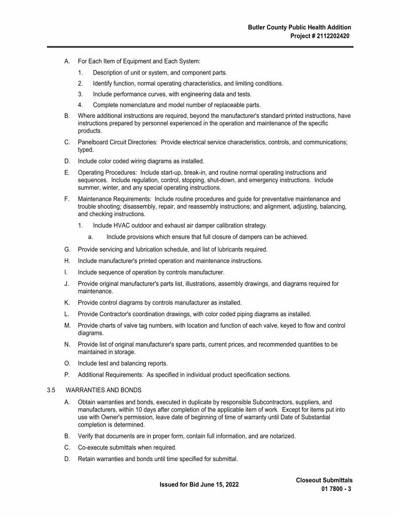
Butler County Public Health Addition Project # 2112202420
Issued for Bid June 15, 2022 Closeout Submittals01 7800 - 3
A. For Each Item of Equipment and Each System:
1. Description of unit or system, and component parts.2. Identify function, normal operating characteristics, and limiting conditions.3. Include performance curves, with engineering data and tests.4. Complete nomenclature and model number of replaceable parts.
B. Where additional instructions are required, beyond the manufacturer's standard printed instructions, have instructions prepared by personnel experienced in the operation and maintenance of the specific products.
C. Panelboard Circuit Directories: Provide electrical service characteristics, controls, and communications; typed.
D. Include color coded wiring diagrams as installed.
E. Operating Procedures: Include start-up, break-in, and routine normal operating instructions and sequences. Include regulation, control, stopping, shut-down, and emergency instructions. Include summer, winter, and any special operating instructions.
F. Maintenance Requirements: Include routine procedures and guide for preventative maintenance and trouble shooting; disassembly, repair, and reassembly instructions; and alignment, adjusting, balancing, and checking instructions.
1. Include HVAC outdoor and exhaust air damper calibration strategy.
a. Include provisions which ensure that full closure of dampers can be achieved.
G. Provide servicing and lubrication schedule, and list of lubricants required.
H. Include manufacturer's printed operation and maintenance instructions.
I. Include sequence of operation by controls manufacturer.
J. Provide original manufacturer's parts list, illustrations, assembly drawings, and diagrams required for maintenance.
K. Provide control diagrams by controls manufacturer as installed.
L. Provide Contractor's coordination drawings, with color coded piping diagrams as installed.
M. Provide charts of valve tag numbers, with location and function of each valve, keyed to flow and control diagrams.
N. Provide list of original manufacturer's spare parts, current prices, and recommended quantities to be maintained in storage.
O. Include test and balancing reports.
P. Additional Requirements: As specified in individual product specification sections.
3.5 WARRANTIES AND BONDS
A. Obtain warranties and bonds, executed in duplicate by responsible Subcontractors, suppliers, and manufacturers, within 10 days after completion of the applicable item of work. Except for items put into use with Owner's permission, leave date of beginning of time of warranty until Date of Substantial completion is determined.
B. Verify that documents are in proper form, contain full information, and are notarized.
C. Co-execute submittals when required.
D. Retain warranties and bonds until time specified for submittal.

Butler County Public Health Addition Project # 2112202420
Closeout Submittals 01 7800 - 4 Issued for Bid June 15, 2022
END OF SECTION
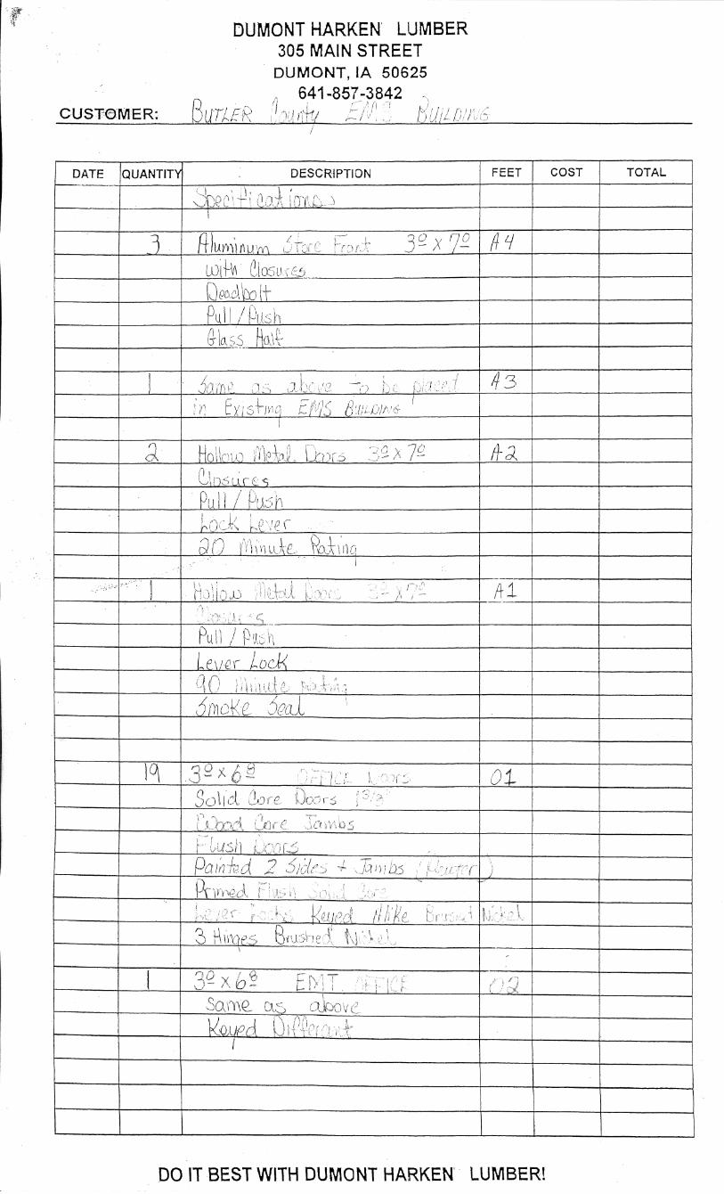
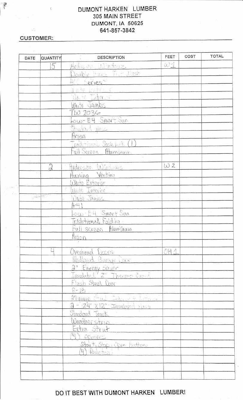
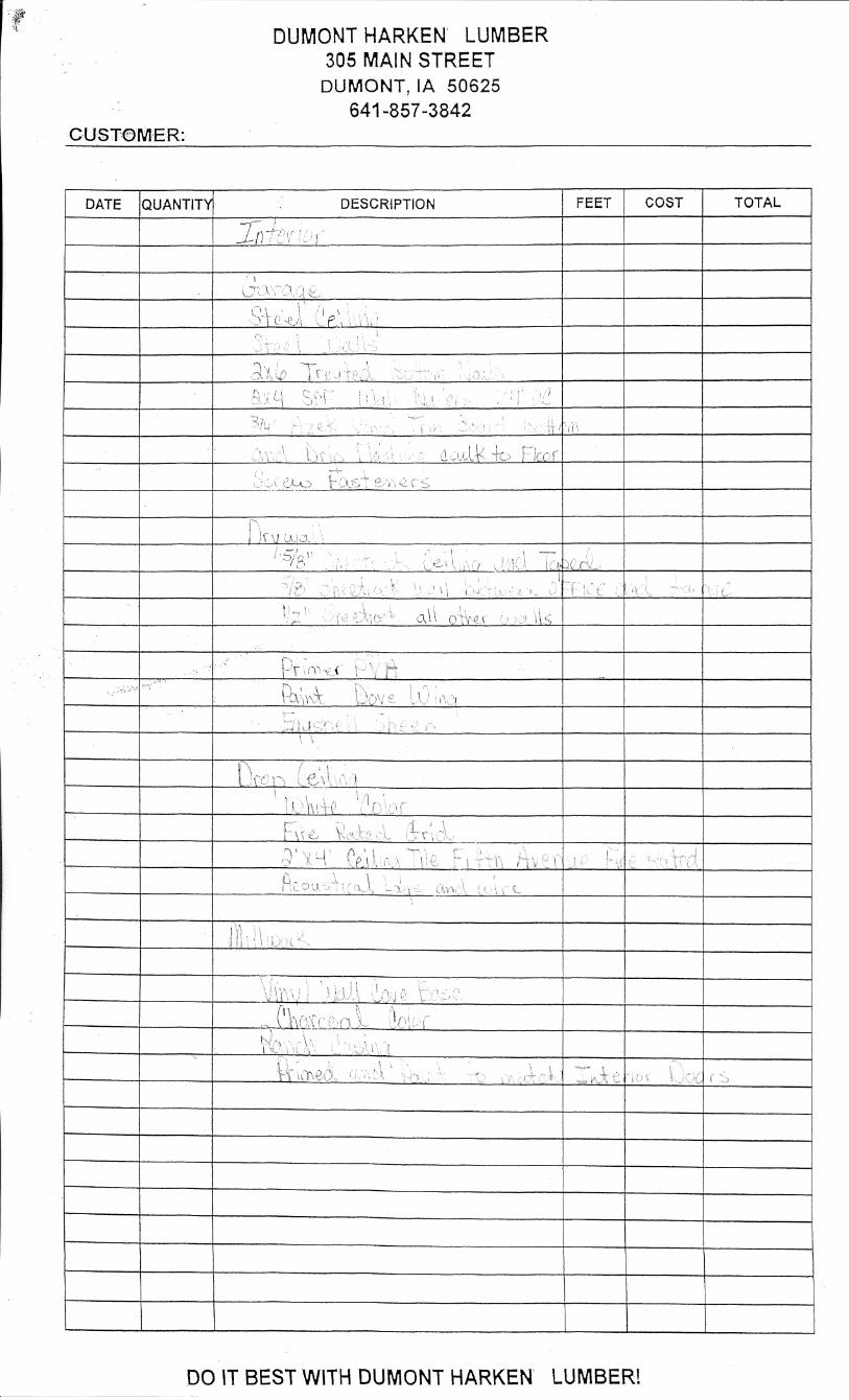
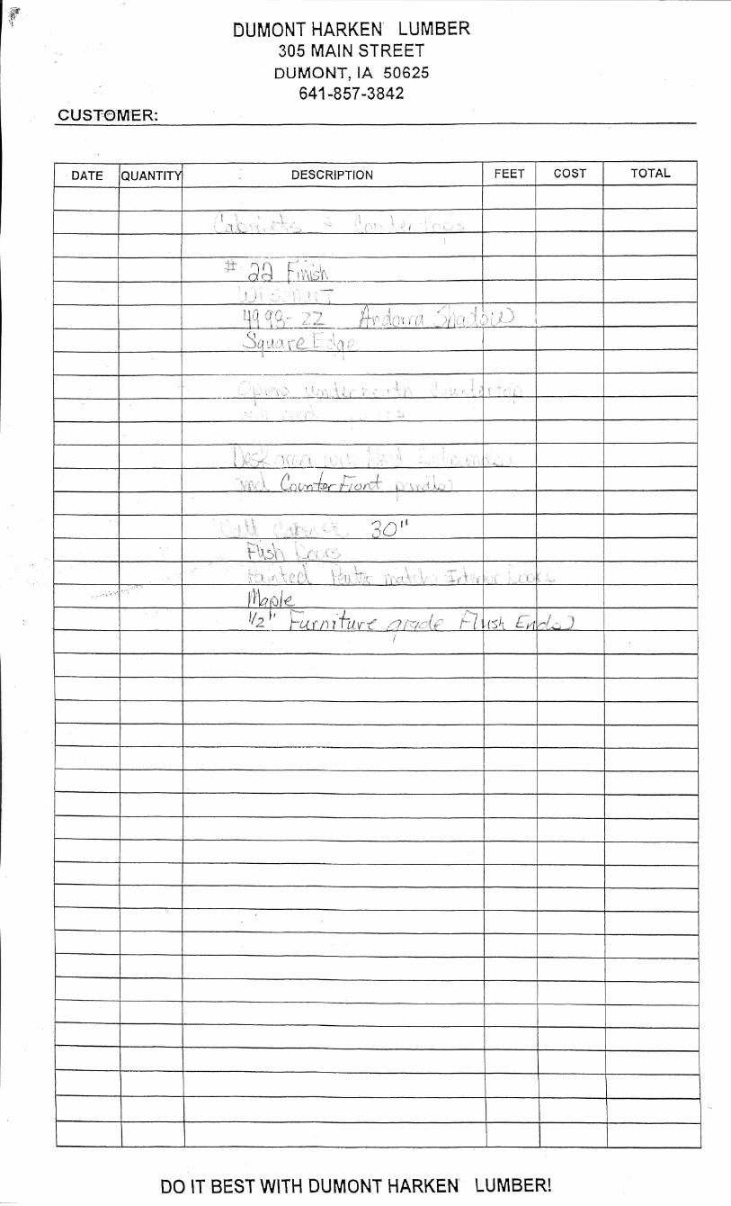
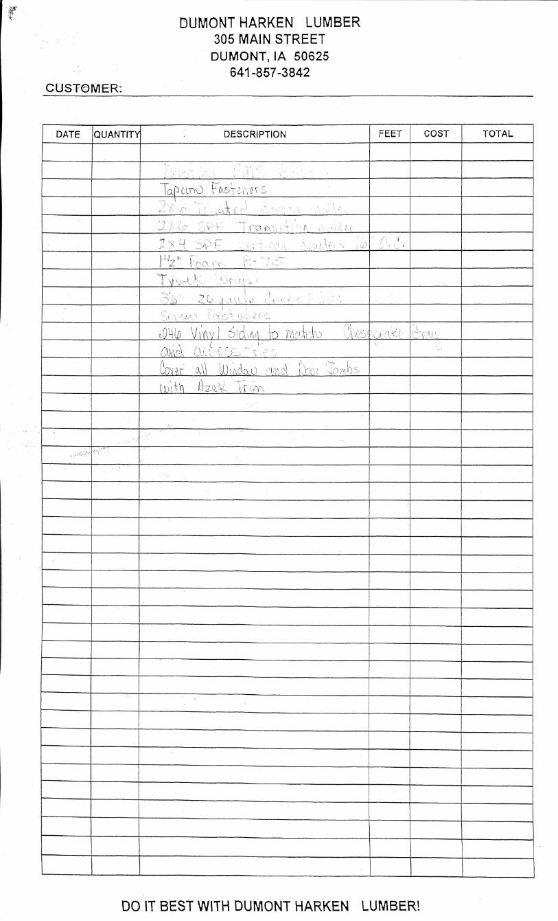
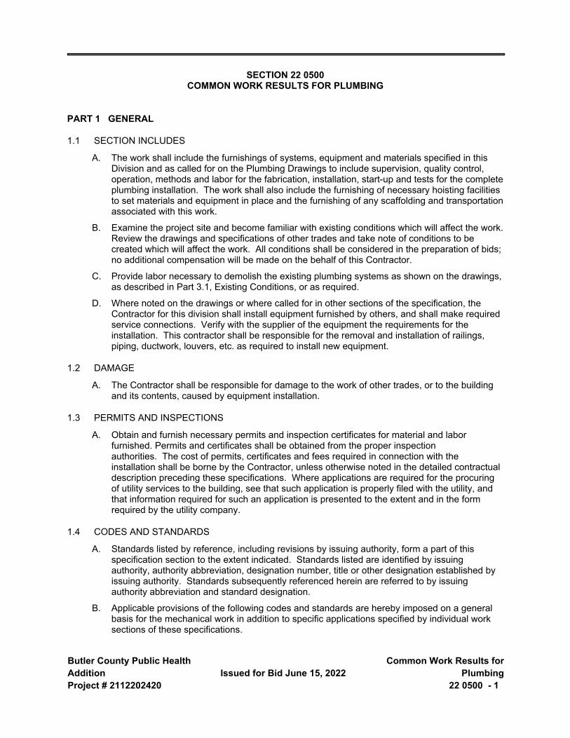
Butler County Public Health AdditionProject # 2112202420
Issued for Bid June 15, 2022 Common Work Results for
Plumbing22 0500 - 1
SECTION 22 0500 COMMON WORK RESULTS FOR PLUMBING
PART 1 GENERAL
1.1 SECTION INCLUDES
A. The work shall include the furnishings of systems, equipment and materials specified in this Division and as called for on the Plumbing Drawings to include supervision, quality control, operation, methods and labor for the fabrication, installation, start-up and tests for the complete plumbing installation. The work shall also include the furnishing of necessary hoisting facilities to set materials and equipment in place and the furnishing of any scaffolding and transportation associated with this work.
B. Examine the project site and become familiar with existing conditions which will affect the work. Review the drawings and specifications of other trades and take note of conditions to be created which will affect the work. All conditions shall be considered in the preparation of bids; no additional compensation will be made on the behalf of this Contractor.
C. Provide labor necessary to demolish the existing plumbing systems as shown on the drawings, as described in Part 3.1, Existing Conditions, or as required.
D. Where noted on the drawings or where called for in other sections of the specification, the Contractor for this division shall install equipment furnished by others, and shall make required service connections. Verify with the supplier of the equipment the requirements for the installation. This contractor shall be responsible for the removal and installation of railings, piping, ductwork, louvers, etc. as required to install new equipment.
1.2 DAMAGE
A. The Contractor shall be responsible for damage to the work of other trades, or to the building and its contents, caused by equipment installation.
1.3 PERMITS AND INSPECTIONS
A. Obtain and furnish necessary permits and inspection certificates for material and labor furnished. Permits and certificates shall be obtained from the proper inspection authorities. The cost of permits, certificates and fees required in connection with the installation shall be borne by the Contractor, unless otherwise noted in the detailed contractual description preceding these specifications. Where applications are required for the procuring of utility services to the building, see that such application is properly filed with the utility, and that information required for such an application is presented to the extent and in the form required by the utility company.
1.4 CODES AND STANDARDS
A. Standards listed by reference, including revisions by issuing authority, form a part of this specification section to the extent indicated. Standards listed are identified by issuing authority, authority abbreviation, designation number, title or other designation established by issuing authority. Standards subsequently referenced herein are referred to by issuing authority abbreviation and standard designation.
B. Applicable provisions of the following codes and standards are hereby imposed on a general basis for the mechanical work in addition to specific applications specified by individual work sections of these specifications.
Butler County Public Health Addition Project # 2112202420
Common Work Results for Plumbing 22 0500 - 2
Issued for Bid June 15, 2022
1. ASHRAE Std 90.1 I-P - Energy Standard for Buildings Except Low-Rise Residential Buildings
2. ANSI/ASME Pressure Piping Standards (B31)3. ICC (IBC) - International Building Code4. ICC (IECC) - International Energy Conservation Code5. ICC (IFC) - International Fire Code6. ICC (IFGC) - International Fuel Gas Code7. ICC (IMC) - International Mechanical Code8. Uniform Plumbing Code9. NFPA Codes and Standards
C. Any product used for dispensing potable water shall meet NSF 61 and NSF 372 testing standards. Third party testing shall be required.
D. If any work indicated on the drawings or specified herein conflicts in any way with any of the rules and regulations of the above Authorities, the Contractor shall promptly notify the Architect/Engineer in writing and do so no less than 72 hours before bids are opened. In the event the Contractor fails to notify the Architect/Engineer and changes are required by said conflicts, the Contractor shall make such changes as are required without additional cost to this Owner.
E. Installations must be safe in every respect, and must not create a condition which will be harmful to building occupants; to operating, installing or testing personnel; to workmen; or to the public. The contractor for each installation shall be solely responsible for providing installations which will meet these conditions. If the Contractor believes that the installation will not be safe for all parties, report these beliefs in writing to the Architect/Engineer before any equipment is purchased or work is installed, giving recommendations. The Architect/Engineer will work out required changes and adjustments in contract price where adjustments are warranted.
1.5 DRAWINGS
A. A complete set of up-to-date Project Drawings and Specifications shall be kept on the site at all times. Prior to installing any of the work, check the drawings for dimensions and see that the work does not interfere with clearance required for ceilings, beams, foundations, finished columns, pilasters, partitions and electrical equipment as shown on the drawings and details. After work is installed and it develops that interferences occur which have not been called to the Architect/Engineer's attention before the installation, the Contractor shall, at his own expense, make such changes in his work as directed by the Architect/Engineer.
B. The contract drawings for plumbing work are in part diagrammatic, intended to convey the scope of work and indicate general arrangement and approximate sizes and locations of equipment and materials. Where job conditions require reasonable changes in indicated locations and arrangement, the Contractor shall make such changes as directed by the Architect/Engineer, without additional cost to the Owner.
C. Because of the scale of the drawings, certain basic items such as pipe fittings, access panels, and sleeves may not be shown; but where such items are required by other sections of these specifications or where they are required by the nature of the work, they shall be furnished and installed. Rough-in dimensions and locations shall be verified with the supplier of equipment furnished by other trades, or by the Owner, prior to the time of roughing-in.
Butler County Public Health Addition Project # 2112202420
Issued for Bid June 15, 2022 Common Work Results for
Plumbing22 0500 - 3
D. Equipment specification may not deal individually with minute items required such as components, parts, controls and devices which may be required to produce the equipment performance specified, or as required to meet the equipment warranties. Where such items are required, they shall be included by the supplier of the equipment, whether or not specifically called for.
E. The drawings and the specifications are cooperative and supplementary. It is the intent of both said drawings and specifications to cover all mechanical requirements in their entirety as nearly as possible. The Contractor shall closely check the drawings and specifications for any obvious errors or omissions and bring any such condition to the attention of the Architect/Engineer prior to the receipt of bids, in order to permit clarification by means of a mailed Addendum. If there is no question prior to the bid proposal date, the Architect/Engineer shall assume that the drawings and specifications are complete and correct and will expect the intent of said documents to be complied with, and the installation to be complete in all respects, according to said intent.
F. Locate equipment which must be serviced, operated or maintained in fully accessible positions. Minor deviations from the contract drawings may be made to allow for better accessibility, but changes of magnitude, or which involve extra cost, shall not be made without prior approval. Ample space shall be allowed for removal of parts that may require replacement or service in the future.
G. All valves, pumps, etc. shall be accessible for maintenance purposes. Locate items carefully and coordinate with other trades so that each valve and piece of equipment is accessible and functional. Items located above a non-accessible ceiling, chase, or soffit shall be accessible through an access door. Coordinate location of access doors with the general contractor.
1.6 RESPONSIBILITY
A. The Contractor's responsibility shall not end with the installation and connecting of the various apparatus. It shall include the services of an experienced superintendent, who shall be constantly in charge of the work, together with the qualified journeymen, helpers and laborers required to properly unload, install, connect, adjust, start, operate and test the work involved, including equipment and materials furnished by other trades or by the Owner, until such time as the entire plumbing installation functions properly in every detail.
1.7 COORDINATION
A. Coordinate the work with other trades prior to installation.
B. No piping or equipment, which is foreign to the electrical equipment, or architectural appurtenances shall be run over the top of any electrical panels or electrical equipment, in accordance with NEC 110.26. This does not prohibit sprinkler protection for the installation.
C. The determination of quantities of material and equipment required shall be made from the drawings. Schedules on the drawings and in the specifications are completed as an aid, but where discrepancies arise, it shall be the Contractor's responsibility to provide the required quantity.
D. Where the specifications state that equipment shall be furnished, installed or provided, it shall be understood to mean this Contractor shall furnish and install completely, unless it is specifically stated that the equipment is to be furnished and installed by others.
E. The Architect/Engineer reserves the right to determine space priority of the contractors in the event of interference between the piping and equipment of the various contractors. Conflicts between the drawings and specifications, or between requirements set forth for the various trades, shall be called to the attention of the Architect/Engineer. If clarification is not asked for
Butler County Public Health Addition Project # 2112202420
Common Work Results for Plumbing 22 0500 - 4
Issued for Bid June 15, 2022
prior to the taking of bids, it will be assumed that none is required, and that the Contractor has submitted his bid in conformance with plans and specifications as issued and that no interference exists.
F. No piping or equipment foreign to an elevator hoistway and machine room shall be run inside the hoistway or machine room in accordance with NEC 620.37 and ASME A17.1 Safety Code for Elevators and Escalators.
1.8 GUARANTEE AND MAINTENANCE
A. Materials and equipment shall be guaranteed to be free from defects and to be new equipment; no secondhand, used or salvaged equipment will be allowed. The Owner's existing equipment which is to be relocated or reinstalled under this contract shall be refurbished, cleaned and repaired, and made subject to the guarantee and maintenance as herein specified, unless specifically noted otherwise.
B. Keep the entire portion of the work in repair, without additional cost to the Owner, so far as defects in workmanship, apparatus, material or construction are concerned for one (1) year from the date of final acceptance, except as otherwise specified herein.
C. Equipment which fails to meet performance ratings as specified and shown on the drawings shall be removed and replaced by new equipment that meets the specified requirements, without additional cost to the Owner.
D. Materials and workmanship shall be subject to the review of the Architect/Engineer, in whose presence various tests shall be made as required by these specifications.
PART 2 PRODUCTS
2.1 SUBMITTALS
A. Submit shop drawings and catalog data for plumbing equipment as called for in Division 01 - General Requirements.
B. Submittal data for plumbing equipment shall consist of shop drawings and/or catalog cuts showing technical data necessary to evaluate the material or equipment to include dimensions, wiring diagrams, performance curves, rating, and other descriptive data necessary to describe fully the item proposed and its operating characteristics. Shop drawings shall be submitted on equipment and materials as required by the specifications.
C. Approval of materials, including alternate or substitute items, shall be obtained in writing from the Architect/Engineer, verbal approval will not be considered binding.
D. Shop drawings shall be submitted and shall have been signed, checked, approved, and initialed by the Contractor prior to submittal to the Architect/Engineer. The Architect/Engineer will review shop drawings to aid in interpreting the plans and specifications, and will in so doing assume that the shop drawings conform to specified requirements set forth in this specification. The approval of the shop drawing by the Architect/Engineer does not relieve the Contractor of the responsibility of complying with elements of the specification. The name of the job, Architect/Engineer, location, and specification section shall appear on all pages of shop drawings. Equipment marks (such as S-1, WH-1) shall be indicated for each item.
E. Near completion of project, before conducting Owner orientation and training sessions and before authorization of final payment, submit to the Owner or their designated Representative for review: three (3) sets of installation and operational information, parts lists, and
Butler County Public Health Addition Project # 2112202420
Issued for Bid June 15, 2022 Common Work Results for
Plumbing22 0500 - 5
maintenance instructional manuals. These OMMs shall be organized, formatted and bound in accordance with Division 01 - General Requirements.
F. At the completion of the project, prepare and submit to the Owner record drawings showing the location of piping and valves. Drawing shall give accurate dimensions of such equipment for future use by the Owner. This drawing shall be submitted as soon as work is completed and before authorization of final payment.
2.2 SUBCONTRACTORS AND MATERIALS
A. Submit to the Architect/Engineer for review, when requested, a list of subcontractors, materials and equipment proposed to be used. The list must be reviewed by the Architect/Engineer before this Contractor may enter into any subcontractual agreement. Equipment, materials, and devices, etc. shall be subject to the review of the Architect/Engineer, whether or not said items are herein specified.
2.3 STANDARDS OF MATERIALS AND WORKMANSHIP
A. Materials shall be new, complete with manufacturer's guarantee or warranty, and shall be as listed by Underwriters Laboratories (UL), Inc., American Water Works Association (AWWA), American Gas Association (AGA), etc., if a standard has been established by that agency for the type of material.
B. Materials shall also comply with applicable standards of the National Electrical Manufacturer's Association, National Board of Fire Underwriters, National Fire Protection Association, National Safety Council, National Bureau of Standards, the National Electrical Code and the Williams-Steiger Occupational Safety and Health Act of 1970. Such standards are hereby made a part of these specifications.
C. Work shall be performed by workmen skilled in the particular craft, shall be executed in a workmanlike manner, and shall present a neat mechanical appearance when completed. Align, level and adjust equipment for satisfactory operation, and install so that connecting and disconnecting of piping and accessories can be made readily and so that parts are easily accessible for inspection, operation and maintenance. Methods and techniques of installation shall be subject to the review of the Architect/Engineer.
D. Materials shall be the standard product of a reputable manufacturer regularly engaged in the manufacture of the specific product. Materials of the same type of class shall be the products of one manufacturer. For example, faucets shall be from the same manufacturer.
E. Materials shall be protected from damage, and stored indoors or protected from the weather at all times, unless other storage arrangements are approved by the Architect/Engineer.
F. Bearing lubrication fittings shall be as recommended by the manufacturer and shall be extended, where necessary, to an accessible location.
G. Material and equipment shall be installed in strict accordance with the manufacturer's recommendations.
2.4 MATERIAL SUBSTITUTIONS
A. Proposals as submitted shall be based on the products specifically named in the specification or on the drawings. Material or equipment by manufacturers other than those specified may be used only by permission of the Architect/Engineer. Such permission for substitution must be requested, in writing and in accordance with Division 01 - General Requirements.
Butler County Public Health Addition Project # 2112202420
Common Work Results for Plumbing 22 0500 - 6
Issued for Bid June 15, 2022
B. The Architect/Engineer reserves the sole right for the approval of proposed material or equipment, and the phrase, "or approved equivalent", used in these specifications, or on the drawings, shall be interpreted to mean an equivalent approved by the Architect/Engineer.
C. Changes required by alternate equipment shall be made at no additional cost to the Owner; and costs incurred by other trades, public utilities or the Owner, as a result of the use of such equipment, shall be the responsibility of the Contractor.
D. Furnish to the Architect/Engineer, when requested, samples of proposed material or equipment substitutions. These samples shall remain with the Architect/Engineer as long as needed.
E. Identify the differences in alternate material or equipment as compared to that specified, and indicate the benefits to the project as a result of selecting the alternative.
F. The Architect/Engineer reserves the right to refuse approval of equipment which does not meet the specification, in their opinion, or of equipment for which no local experience of satisfactory service is available. The Architect/Engineer further reserves the right to reject equipment for which maintenance service and the availability of replacement parts is questionable.
2.5 JOINING MATERIALS
A. Refer to individual Division 22 piping sections for special joining materials not listed below.
B. Pipe-Flange Gasket Materials: Suitable for chemical and thermal conditions of piping system contents.
1. ASME B16.21, nonmetallic, flat, asbestos-free, 1/8-inch (3.2-mm) maximum thickness unless thickness or specific material is indicated.
a. Full-Face Type: For flat-face, Class 125, cast-iron and cast-bronze flanges.
b. Narrow-Face Type: For raised-face, Class 250, cast-iron and steel flanges.
1) AWWA C110, rubber, flat face, 1/8 inch (3.2 mm) thick, unless otherwise indicated; and full-face or ring type, unless otherwise indicated.
C. Flange Bolts and Nuts: ASME B18.2.1, carbon steel, unless otherwise indicated.
D. Plastic, Pipe-Flange Gasket, Bolts, and Nuts: Type and material recommended by piping system manufacturer, unless otherwise indicated.
E. Solder Filler Metals: ASTM B 32, lead-free alloys. Include water-flushable flux according to ASTM B 813.
F. Brazing Filler Metals: AWS A5.8, BCuP Series, copper-phosphorus alloys for general-duty brazing, unless otherwise indicated; and AWS A5.8, BAg1, silver alloy for refrigerant piping, unless otherwise indicated.
G. Welding Filler Metals: Comply with AWS D10.12 for welding materials appropriate for wall thickness and chemical analysis of steel pipe being welded.
H. Solvent Cements for Joining Plastic Piping:
1. ABS Piping: ASTM D 2235.2. CPVC Piping: ASTM F 493.3. PVC Piping: ASTM D 2564. Include primer according to ASTM F 656.4. PVC to ABS Piping Transition: ASTM D 3138.5. Fiberglass Pipe Adhesive: As furnished or recommended by pipe manufacturer.
Butler County Public Health Addition Project # 2112202420
Issued for Bid June 15, 2022 Common Work Results for
Plumbing22 0500 - 7
2.6 TRANSITION FITTINGS
A. AWWA Transition Couplings: Same size as, and with pressure rating at least equal to and with ends compatible with piping to be joined.
1. Available Manufacturers:
a. Cascade Waterworks Mfg. Co.
b. Dresser Industries, Inc.; DMD Div.
c. Ford Meter Box Company, Incorporated (The); Pipe Products Div.
2. JCM Industries.
a. Smith-Blair, Inc.
b. Viking Johnson.
1) Underground Piping NPS 1-1/2 (DN 40) and Smaller: Manufactured fitting or coupling.
2) Underground Piping NPS 2 (DN 50) and larger: AWWA C219, metal sleeve-type coupling.
3) Aboveground Pressure Piping: Pipe fitting.3. Plastic-to-Metal Transition Fittings: CPVC one-piece fitting with manufacturer's Schedule
80 equivalent dimensions; one end with threaded brass insert, and one solvent-cement-joint end.
a. Available Manufacturers:
1) Eslon Thermoplastics.4. Plastic-to-Metal Transition Adaptors: One-piece fitting with manufacturer's SDR 11
equivalent dimensions; one end with threaded brass insert, and one solvent-cement-joint end.
a. Available Manufacturers:
1) Thompson Plastics, Inc.5. Plastic-to-Metal Transition Unions: MSS SP-107, CPVC four-part union. Include brass
end, solvent-cement-joint end, rubber O-ring, and union nut.
a. Available Manufacturers:
1) NIBCO INC.2) NIBCO, Inc.; Chemtrol Div.
6. Flexible Transition Couplings for Underground Nonpressure Drainage Piping: ASTM C 1173 with elastomeric sleeve, ends same size as piping to be joined, and corrosion-resistant metal band on each end.
a. Available Manufacturers:
1) Cascade Waterworks Mfg. Co.2) Fernco, Inc.3) Mission Rubber Company.4) Plastic Oddities, Inc.
2.7 DIELECTRIC FITTINGS
Butler County Public Health Addition Project # 2112202420
Common Work Results for Plumbing 22 0500 - 8
Issued for Bid June 15, 2022
A. Description: Combination fitting of copper alloy and ferrous materials with threaded, solder-joint, plain, or weld-neck end connections that match piping system materials.
B. Insulating Material: Suitable for system fluid, pressure, and temperature.
C. Dielectric Unions: Factory-fabricated, union assembly, for 250-psig (1725-kPa) minimum working pressure at 180 deg F (82 deg C).
1. Available Manufacturers:
a. Capitol Manufacturing Co.
b. Central Plastics Company.
c. Eclipse, Inc.
d. Epco Sales, Inc.
e. Hart Industries, International, Inc.
2. Watts Industries, Inc.; Water Products Div.
a. Zurn Industries, Inc.; Wilkins Div.
2.8 GROUT
A. Description: ASTM C 1107, Grade B, nonshrink and nonmetallic, dry hydraulic-cement grout.
B. Characteristics: Post-hardening, volume-adjusting, nonstaining, noncorrosive, nongaseous, and recommended for interior and exterior applications.
1. Design Mix: 5000-psi (34.5-MPa), 28-day compressive strength.2. Packaging: Premixed and factory packaged.
PART 3 EXECUTION
3.1 EXISTING CONDITIONS
A. Examine the existing buildings and grounds or site and become familiar with the conditions as they exist, or that will in any manner affect the work under this contract. No allowance will be made subsequently, in this connection, on behalf of the Contractor for any error or negligence by the Contractor.
B. Existing equipment, such as duct or pipe, in or on the existing building and grounds which is to be replaced, or which interferes in any way with the remodeling of the existing facilities and/or installation of new equipment, shall be removed from the premises or relocated by this Contractor, as directed by the Architect/Engineer. Do not remove from the premises any equipment that may have maintenance value to the Owner without permission of the Owner. Equipment, duct or pipe not to be reused shall be removed from the premises, unless otherwise noted herein or shown on the drawings.
C. Where existing equipment is removed or changed, all piping no longer in service shall be removed and stubs plugged as directed by the Architect/Engineer. Building surfaces damaged and openings left by removal of equipment shall be repaired by the proper trades and paid for by this Contractor, unless otherwise noted on the drawings. The cutting and fitting shall be done by this Contractor. The cutting of floor, ceiling or wall surfaces shall be done by this Contractor with extreme care, in order to avoid any disrupting or damage of existing utility services which may be encountered. Coordinate with other trades and with the General
Butler County Public Health Addition Project # 2112202420
Issued for Bid June 15, 2022 Common Work Results for
Plumbing22 0500 - 9
Contractor or Construction Manager to minimize the damage to the building in order to reduce the amount of patching required.
D. Where new openings are cut and concealed piping is encountered, such items shall be removed or relocated as required. Where systems to be removed stub through floors, walls or ceilings, openings shall be patched so that no evidence of the former installation remains.
E. Existing active services (water, gas, sewer, electric), when encountered, shall be protected against damage. Do not prevent or disturb operation of active services that are to remain. If active services are encountered which require relocation, make request to authorities with jurisdiction for determination of procedures. Where existing services are to be abandoned, they shall be terminated in conformance with requirements of the utility or municipality having jurisdiction.
F. The location, size and elevation of underground utilities shown on the drawings are in accordance with data supplied by the Owner and/or the various utility companies. The Contractor shall verify this data and shall report any discrepancies to the Architect/Engineer, in writing, before submitting his bid.
3.2 INTERRUPTION OF SERVICE
A. Changes in service shall be made so as to provide a minimum of interference with the operation of services in the building. When changes require shutdown of building services, notify the proper building authorities no less than 48 hours in advance and obtain approval from these authorities before making changes. Such notices shall give duration and nature of shutdown. Temporary arrangements shall be approved by the Architect/Engineer and/or Owner.
B. Any and all interruptions to building services shall be in accordance with Division 01 - General Requirements.
3.3 PIPING SYSTEMS - COMMON REQUIREMENTS
A. Drawing plans, schematics, and diagrams indicate general location and arrangement of piping systems. Indicated locations and arrangements were used to size pipe and calculate friction loss, expansion, pump sizing, and other design considerations. Install piping as indicated unless deviations to layout are approved on Coordination Drawings.
B. Install piping in concealed locations, unless otherwise indicated and except in equipment rooms and service areas.
C. Install piping indicated to be exposed and piping in equipment rooms and service areas at right angles or parallel to building walls. Diagonal runs are prohibited unless specifically indicated otherwise.
D. Install piping above accessible ceilings to allow sufficient space for ceiling panel removal.
E. Install piping at indicated slopes.
F. Install fittings for changes in direction and branch connections.
G. Install piping to allow application of insulation.
H. Select system components with pressure rating equal to or greater than system operating pressure.
3.4 OPENINGS, CUTTING, AND PATCHING
Butler County Public Health Addition Project # 2112202420
Common Work Results for Plumbing 22 0500 - 10
Issued for Bid June 15, 2022
A. The General Contractor shall coordinate the placing of openings in the new structure, as required for the installation of the plumbing work.
B. Furnish to the General Contractor the accurate locations and sizes for required openings. This shall not relieve this Contractor of the responsibility of checking to assure that proper size openings are provided. When additional patching is required due to this Contractor's failure to inspect this work, this Contractor shall make arrangements for the patching required to properly close the opening, to include patch painting. This Contractor shall pay any additional cost incurred in this respect.
C. When cutting and patching of the structure is made necessary due to this Contractor's failure to install piping, sleeves or equipment on schedule, or due to this Contractor's failure to furnish, on schedule, the information required for the leaving of openings, it shall be this Contractor's responsibility to make arrangements for this cutting and patching. This Contractor shall pay any additional cost incurred in this respect.
D. Provide cutting and patching and patch painting in the existing structure, as required for the installation of the work. Furnish lintels and supports as required for openings. Cutting of structural support members will not be permitted without prior approval of the Architect/Engineer. Extent of cutting shall be minimized. Use core drills, power saws or other machines which will provide neat, minimum openings. Patching shall match adjacent materials and textures and shall be performed by craftsmen skilled in the respective craft required.
E. Underfloor Plumbing Work:
1. Contractor shall coordinate all related activity with General Contractor at least 24 hours before beginning construction activity.
2. Contractor, before saw-cutting floor, must first field verify all existing piping service, sizes, locations, depths, flow directions as well as coordinate with any other trades who may have utilities such as wires or conduits concealed beneath floor and which may be subject to damage and subsequent service interruptions. The cost to repair any damaged utilities shall be borne by The Contractor.
3. Contractor shall be responsible for erecting and maintaining suitable temporary construction barriers and enclosures for containment of all construction dust and debris. Enclosures and barriers shall be maintained under negative pressure and fans and filters as needed to assist with containment.
3.5 EXCAVATION AND BACKFILL
A. See Division 31 - Trenching and Backfilling for requirements for trench excavation, backfill, and compaction.
B. Contractor shall coordinate all related activity with General Contractor at least 24 hours before beginning construction activity.
C. The Contractor shall be responsible for erecting and monitoring of all safety barricades and related protection around excavation and work areas.
D. Trenches and excavations may be backfilled by the Contractor only after required testing has been satisfactorily performed and locations of connections and appurtenances which will be concealed have been recorded by the Contractor in the construction record documents.
E. Bedding:
1. Gravity Storm Sewer or Sanitary Sewer Pipe Bedding Material:
a. Rigid Pipe:
Butler County Public Health Addition Project # 2112202420
Issued for Bid June 15, 2022 Common Work Results for
Plumbing22 0500 - 11
1) Rigid gravity storm or sanitary sewer pipe shall be provided with compacted granular bedding having a minimum thickness of 4" (100 mm) or 1/8th of the outside pipe diameter, whichever is greater.
2) Clean gravel or crushed rock shall meet the following gradation for rigid sewer pipe. (RCP, DIP, VCP):
b. Non-Rigid Pipe:
1) Non-rigid gravity storm or sanitary sewer pipe shall be provided with compacted granular bedding having a minimum thickness of 4" (100 mm) or 1/4th of the outside pipe diameter, whichever is greater.
2) Gravel or crushed rock shall meet the following gradation for non-rigid sewer pipe: 100% passing a ¾" (19 mm) sieve, 50-80% passing a No. 4 (4.75 mm) sieve, and 25-60% passing a No. 8 (2.36 mm) sieve. (IADOT Gradation No. 10).
2. Water mains or sanitary sewer force mains may be installed with undisturbed or compacted soil bedding provided the subgrade is consistent and the Contractor provides hand excavation for bells such that the pipe barrel bears evenly on the subgrade.
3. Contractor shall be responsible for prompt cleanup and disposal of all unsuitable or excess bedding materials.
F. Backfill:
1. Suitable excavated material: Free of cinders, ashes, refuse, rocks, pavement fragments, vegetative or organic matter. Unless noted otherwise on the plans, sand shall not be used.
2. Granular backfill shall be crushed limestone or gravel with 100% passing a ¾" (19 mm) sieve, 50-80% passing a No. 4 (4.75 mm) sieve, and 25-60% passing a No. 8 (2.36 mm) sieve. (IADOT Gradation No. 10)
3. Place backfill simultaneously on both sides of pipe to prevent displacement and place at an angle so that impact on installed pipe is minimized.
4. Backfill in the pipe envelope (top of bedding to a point 12" (300 mm) above the pipe) shall be hand placed. Material shall be of even consistency and free of clumps and boulders, finely divided, and shall be compacted to 90% maximum Standard Proctor Density. Material within the pipe envelope shall be the same as specified for trench backfill, unless noted otherwise on the Plans
5. Contractor shall be responsible for prompt cleanup and disposal of all unsuitable or excess backfill materials.
3.6 CONCRETE AND MASONRY WORK
A. Concrete work included herein or shown on the drawings shall be in conformance with Division 3 - Concrete.
B. Concrete work included herein or shown on the drawings shall be done only by experienced cement finishers. Brickwork, where included, shall be laid only by experienced brick masons. Brick shall be of uniform size, hard burned, and shall be laid in cement mortar, except for patch work at a location where cement and lime mortar has previously been used. Exposed, finish brickwork shall match existing brickwork as closely as practical and shall be to the satisfaction of the Architect/Engineer and Owner.
C. Concrete bases and pads for mechanical equipment will be furnished by General Contractor. This Contractor shall coordinate size and location.
Butler County Public Health Addition Project # 2112202420
Common Work Results for Plumbing 22 0500 - 12
Issued for Bid June 15, 2022
D. Concrete bases and pads for mechanical equipment shall be furnished by this Contractor. Size bases to extend minimum of 4" beyond equipment base in any direction, and 4" above finished floor elevation. Construct of reinforced concrete, roughen floor slab beneath base for bond, and provide steel rod anchors between floor and base. Locate anchor bolts using equipment manufacturer's templates. Chamfer top and edge corners.
E. Locate, furnish and install all support, hanger and equipment anchor bolts and related hardware.
F. Underfloor Plumbing Work:
1. Contractor shall coordinate all related activity with General Contractor at least 24 hours before beginning construction activity.
2. Contractor shall saw cut, remove and properly dispose of concrete and related debris as required to accommodate new underfloor piping and fixtures.
3. Patch floor to match adjacent floor textures and reinforce with #3 rebar, 18” O.C. (drill and grout 3” imbed).
4. Unless noted otherwise, concrete shall be commercial grade with a minimum 28-day compressive strength of 3,000 PSI. Do not allow air content of troweled finished floors to exceed 3%
3.7 ROOF OPENINGS
A. Roof openings required by this Contractor that are not shown on the Structural or Architectural Drawings shall be cut and adequately reinforced by an experienced roofing contractor.
B. Roof penetrations for piping shall be through curbed roof openings. Equipment supports shall be by curbed and flashed runners meeting current National Roofing Contractor Association (NRCA) standards and details. Pitch pockets, pitch pans, and wood blocking are not acceptable.
C. All roof work shall be completed such that it does not void any existing roof warranty.
3.8 PAINTING
A. The finish of any item that has been marred, scratched or damaged in any way by this Contractor shall be repainted at the expense of this Contractor, and to the satisfaction of the Architect/Engineer and the Owner.
B. Painting and finishing of exposed mechanical systems including piping and duct shall be as shown on the drawings and per Division 9 - Finishes.
3.9 CLEANING
A. Keep the premises clean of all dirt and debris, caused by the work in accordance with Division 1 - General Requirements.
B. Keep the premises clean of all debris caused by the work at all times, and keep materials stored, in areas designated by the Owner, in such a manner as not to interfere with the progress of the work of other Contractors or with the operation of existing facilities.
C. At the conclusion of the construction, the site shall be thoroughly cleaned of all rubble, debris and unused material and shall be left in good order. Closed off spaces shall be cleaned of waste such as material, cartons, and wood frame members used in the construction.
3.10 SUSPENSION FROM WOOD STRUCTURAL MEMBERS
Butler County Public Health Addition Project # 2112202420
Issued for Bid June 15, 2022 Common Work Results for
Plumbing22 0500 - 13
A. In general, concentrated or other loads shall not be suspended directly from the bottom of wood structural members, unless approved by the Architect/Engineer. Loads suspended from open web joists or trusses may be transferred to the bottom chord of the structural member at the panel points. Loads suspended from solid web joists shall be transferred to the joists only through the top flange or web. Suspension systems shall be reviewed by the Architect/Engineer.
3.11 WIRING FOR PLUMBING EQUIPMENT
A. The Division 26 Contractor shall provide power including connection to all electrically powered equipment furnished by the Division 22 Contractor. Where electrical disconnect switches are not explicitly specified to be furnished as part of Division 22 equipment, the Electrical Contractor shall furnish suitable type(s) and properly rated electrical disconnect switches for all said mechanical equipment.
B. Provide integral wiring, alarm wiring, control wiring, temperature control wiring and interlock wiring for equipment furnished, whether or not such wiring is furnished by the equipment vendor.
C. Except as noted otherwise or where other sections call for motor starters to be furnished by manufacturers as part of their equipment, the Division 26 Electrical Contractor shall furnish motor starters as required for motors furnished by this Division 22 Contractor.
D. Furnish shop drawings including but not limited to detailed schedules and wiring diagrams to other interested trades including Division 26 electrical contractor for all electrically powered equipment furnished. Schedules shall include: electrical loads and characteristics, max. overcurrent fuse protection / circuit breaker needs, disconnect requirements, motor starter requirements and motor horsepower(s). Include drawings as needed to depict locations of electrical and control panels, service clearances, disconnects as well as wiring connection points.
E. The Division 22 Contractor shall be responsible to pay for all additional costs incurred due to equipment substitutions by Division 22 Contractor, which require either larger electrical service or service of a different electrical characteristic than scheduled on the Drawings.
F. Prior to bid submission, this Division 22 Contractor shall review the Electrical Drawings and promptly bring to the attention of the Architect/Engineer, any omissions or errors in the electrical services required for equipment proposed to be furnished.
3.12 PROTECTION
A. Special steps shall be taken as necessary for the protection of equipment and materials furnished under Division 22. Equipment and materials shall be protected by Contractor from any physical damage due to weather elements, dirt, dents, sheet rock installation, and painting until the project is completed. Damage, if incurred, shall be promptly repaired at no additional cost to Owner, as-needed to restore equipment and materials to original as-new condition.
B. Protection of equipment during the finishing (sheet rock, plastering and painting) of the building interior shall be the responsibility of the contractor or contractors performing that work. This shall not relieve this Division 22 Contractor of the ultimate responsibility of checking and ensuring that adequate protection is provided and maintained at all times.
C. Where the installation or connection of equipment requires Division 22 Contractor to work in areas previously finished by other Contractors, the Division 22 Contractor shall be responsible to ensure that such finished areas are adequately protected and are not marred, soiled or otherwise damaged during the course of their said work. If damage occurs this Division 22
Butler County Public Health Addition Project # 2112202420
Common Work Results for Plumbing 22 0500 - 14
Issued for Bid June 15, 2022
Contractor shall be responsible to arrange for the other Contractors to repair and refinish any damaged areas and shall pay for all repair, rework and refinishing required.
D. When heavy materials must be placed upon or transported over the roof deck, sheeting shall be placed to distribute the weight and support such materials. Any damage shall be immediately corrected at no cost to the Owner.
3.13 ASBESTOS IDENTIFICATION AND CONTROL
A. In the event that suspected asbestos containing material (ACM) is encountered during the course of the work, cease operations in the immediate area and promptly notify both the Owner and Architect/Engineer. Suspected materials will then be sampled and analyzed by the Owner’s Representative.
B. Should ACM be confirmed, the Owner's Representative shall direct the abatement procedures. This work shall be awarded either by subcontract to the Contractor or under a separate contract.
C. During abatement operations, cease operations in the immediate area of the abatement. Operations in other areas of the project may be performed, but care must be taken to control dust to avoid contamination of air monitoring samples. The Contractors shall coordinate activities with the asbestos abatement contractor as well as the Owner’s Representative.
D. Should no ACM be identified, operations in the restricted areas may be resumed. At the discretion of the Owner or Owner’s representative, any schedule delays caused by identification, analysis or abatement may be added in the form of an extension of time to the contract via a Change Order.
3.14 NOISE AND VIBRATION
A. Contractor shall install all equipment in a such a manner so as to control the transmission of noise and vibration from any installed equipment, components or systems, so the sound level in any occupied area does not exceed NC-35 levels. Contractor shall correct all objectionable noise levels in any occupied areas and at no additional cost to Owner, which are due to improperly installed or isolated equipment, components or systems.
3.15 TESTS AND DEMONSTRATIONS
A. Systems shall be tested and placed in proper working order prior to demonstrating systems to the Owner.
B. Prior to acceptance of the plumbing installation, demonstrate to the Owner or his designated representatives essential features and functions of all systems installed, and instruct the Owner in the proper operation and maintenance of such systems.
C. Furnish the necessary trained personnel to perform the demonstrations and instructions, and arrange to have the manufacturer's representatives for the system present to assist with the demonstrations. The Owner and Contractor shall each sign a certification stating that the training has been performed and the Owner accepts same.
3.16 UTILITY REBATE APPLICATIONS
A. This contractor shall be responsible for gathering information necessary for completing local utility rebate applications, and submitting to the proper utility companies for gas and electric rebates. Potential rebates include high efficiency gas boilers, thermostats, timeclocks, motors, and other items furnished by this plumbing contractor.

Butler County Public Health Addition Project # 2112202420
Issued for Bid June 15, 2022 Common Work Results for
Plumbing22 0500 - 15
END OF SECTION

Butler County Public Health AdditionProject # 2112202420
Issued for Bid June 15, 2022 Common Motor Requirements
for Plumbing Equipment22 0513 - 1
SECTION 22 0513 COMMON MOTOR REQUIREMENTS FOR PLUMBING EQUIPMENT
PART 1 GENERAL
1.1 SECTION INCLUDES
A. General construction and requirements.
B. Applications.
C. Single phase electric motors.
1.2 RELATED REQUIREMENTS
A. Section 26 0583 - Wiring Connections: Electrical characteristics and wiring connections.
1.3 REFERENCE STANDARDS
A. NEMA MG 1 - Motors and Generators 2018.
B. NFPA 70 - National Electrical Code Most Recent Edition Adopted by Authority Having Jurisdiction, Including All Applicable Amendments and Supplements.
1.4 SUBMITTALS
A. See Section 01 3000 - Administrative Requirements for submittal procedures.
B. Product Data: Provide wiring diagrams with electrical characteristics and connection requirements.
C. Certification: Provide manufacturer's literature indicating NEMA premium motor efficiency as tested in accordance with IEEE Standard 112, Test Method B. Provide documentation to verify motors served by variable frequency drives meet NEMA MG1.
D. Test Reports: Indicate test results verifying nominal efficiency and power factor for three phase motors larger than 1/2 horsepower.
E. Manufacturer's Installation Instructions: Indicate setting, mechanical connections, lubrication, and wiring instructions.
F. Operation Data: Include instructions for safe operating procedures.
1.5 COORDINATION
A. Coordinate features of motors, installed units, and accessory devices to be compatible with the following.
1. Motor controllers2. Torque, speed, and horsepower requirements of the load3. Ratings and characteristics of supply circuit and required control sequence.4. Ambient and environmental conditions of installation location.5. Motors for operation with variable speed drives shall include motor shaft grounding kits to
divert adverse shaft currents away from the motor bearings. This contractor shall ensure (via field observation and measurement) that the shaft is effectively grounded upon startup.
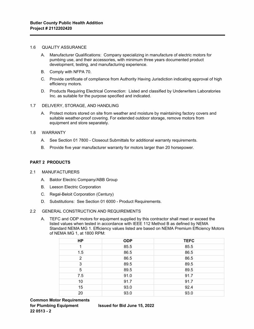
Butler County Public Health Addition Project # 2112202420
Common Motor Requirements for Plumbing Equipment 22 0513 - 2
Issued for Bid June 15, 2022
1.6 QUALITY ASSURANCE
A. Manufacturer Qualifications: Company specializing in manufacture of electric motors for pumbing use, and their accessories, with minimum three years documented product development, testing, and manufacturing experience.
B. Comply with NFPA 70.
C. Provide certificate of compliance from Authority Having Jurisdiction indicating approval of high efficiency motors.
D. Products Requiring Electrical Connection: Listed and classified by Underwriters Laboratories Inc. as suitable for the purpose specified and indicated.
1.7 DELIVERY, STORAGE, AND HANDLING
A. Protect motors stored on site from weather and moisture by maintaining factory covers and suitable weather-proof covering. For extended outdoor storage, remove motors from equipment and store separately.
1.8 WARRANTY
A. See Section 01 7800 - Closeout Submittals for additional warranty requirements.
B. Provide five year manufacturer warranty for motors larger than 20 horsepower.
PART 2 PRODUCTS
2.1 MANUFACTURERS
A. Baldor Electric Company/ABB Group
B. Leeson Electric Corporation
C. Regal-Beloit Corporation (Century)
D. Substitutions: See Section 01 6000 - Product Requirements.
2.2 GENERAL CONSTRUCTION AND REQUIREMENTS
A. TEFC and ODP motors for equipment supplied by this contractor shall meet or exceed the listed values when tested in accordance with IEEE 112 Method B as defined by NEMA Standard NEMA MG 1. Efficiency values listed are based on NEMA Premium Efficiency Motors of NEMA MG 1, at 1800 RPM:
HP ODP TEFC1 85.5 85.5
1.5 86.5 86.52 86.5 86.53 89.5 89.55 89.5 89.5
7.5 91.0 91.710 91.7 91.715 93.0 92.420 93.0 93.0
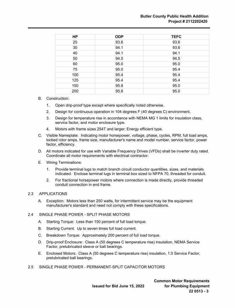
Butler County Public Health Addition Project # 2112202420
Issued for Bid June 15, 2022 Common Motor Requirements
for Plumbing Equipment22 0513 - 3
HP ODP TEFC25 93.6 93.630 94.1 93.640 94.1 94.150 94.5 94.560 95.0 95.075 95.0 95.4
100 95.4 95.4125 95.4 95.4150 95.8 95.0200 95.8 95.0
B. Construction:
1. Open drip-proof type except where specifically noted otherwise.2. Design for continuous operation in 104 degrees F (40 degrees C) environment.3. Design for temperature rise in accordance with NEMA MG 1 limits for insulation class,
service factor, and motor enclosure type.4. Motors with frame sizes 254T and larger: Energy efficient type.
C. Visible Nameplate: Indicating motor horsepower, voltage, phase, cycles, RPM, full load amps, locked rotor amps, frame size, manufacturer's name and model number, service factor, power factor, efficiency.
D. All motors indicated for use with Variable Frequency Drives (VFDs) shall be inverter duty rated. Coordinate all motor requirements with electrical contractor.
E. Wiring Terminations:
1. Provide terminal lugs to match branch circuit conductor quantities, sizes, and materials indicated. Enclose terminal lugs in terminal box sized to NFPA 70, threaded for conduit.
2. For fractional horsepower motors where connection is made directly, provide threaded conduit connection in end frame.
2.3 APPLICATIONS
A. Exception: Motors less than 250 watts, for intermittent service may be the equipment manufacturer's standard and need not comply with these specifications.
2.4 SINGLE PHASE POWER - SPLIT PHASE MOTORS
A. Starting Torque: Less than 150 percent of full load torque.
B. Starting Current: Up to seven times full load current.
C. Breakdown Torque: Approximately 200 percent of full load torque.
D. Drip-proof Enclosure: Class A (50 degrees C temperature rise) insulation, NEMA Service Factor, prelubricated sleeve or ball bearings.
E. Enclosed Motors: Class A (50 degrees C temperature rise) insulation, 1.0 Service Factor, prelubricated ball bearings.
2.5 SINGLE PHASE POWER - PERMANENT-SPLIT CAPACITOR MOTORS
Butler County Public Health Addition Project # 2112202420
Common Motor Requirements for Plumbing Equipment 22 0513 - 4
Issued for Bid June 15, 2022
A. Starting Torque: Exceeding one fourth of full load torque.
B. Starting Current: Up to six times full load current.
C. Multiple Speed: Through tapped windings.
D. Open Drip-proof or Enclosed Air Over Enclosure: Class A (50 degrees C temperature rise) insulation, minimum 1.0 Service Factor, prelubricated sleeve or ball bearings, automatic reset overload protector.
PART 3 EXECUTION
3.1 INSTALLATION
A. Install in accordance with manufacturer's instructions.
B. Install securely on firm foundation. Mount ball bearing motors with shaft in any position.
C. Check line voltage and phase and ensure agreement with nameplate.
D. Verify motor shaft grounding kit is properly installed and adjusted.
E. Verify motor and sheave alignment for all belt driven and direct coupled equipment.
END OF SECTION
Butler County Public Health AdditionProject # 2112202420
Issued for Bid June 15, 2022 Expansion Fittings and Loops
for Plumbing Piping22 0516 - 1
SECTION 22 0516 EXPANSION FITTINGS AND LOOPS FOR PLUMBING PIPING
PART 1 GENERAL
1.1 SECTION INCLUDES
A. Provide material, equipment, labor, and supervision necessary to install expansion joints as required by Drawings and this Section.
B. Flexible pipe connectors.
C. Expansion joints and compensators.
1.2 RELATED REQUIREMENTS
A. Section 22 1005 - Plumbing Piping.
1.3 REFERENCE STANDARDS
A. ASME B16.5 - Pipe Flanges and Flanged Fittings: NPS 1/2 through NPS 24 Metric/Inch Standard 2020.
B. EJMA (STDS) - EJMA Standards Tenth Edition.
C. UL (DIR) - Online Certifications Directory Current Edition.
1.4 SUBMITTALS
A. See Section 01 3000 - Administrative Requirements, for submittal procedures.
B. Product Data:
1. Flexible Pipe Connectors: Indicate maximum temperature and pressure rating, face-to-face length, live length, hose wall thickness, hose convolutions per foot (meter) and per assembly, fundamental frequency of assembly, braid structure, and total number of wires in braid.
2. Expansion Joints: Indicate maximum temperature and pressure rating, and maximum expansion compensation.
C. Design Data: Indicate selection calculations.
D. Manufacturer's Instructions: Indicate manufacturer's installation instructions, special procedures, and external controls.
E. Maintenance Data: Include adjustment instructions.
F. Project Record Documents: Record installed locations of flexible pipe connectors, expansion joints, anchors, and guides.
1.5 DELIVERY, STORAGE, AND HANDLING
A. Deliver materials in manufacturer's original unopened, undamaged containers with identification labels intact.
B. During loading, transporting, unloading, and storage, the Contractor shall exercise care to prevent damage to materials.
C. Accept equipment on site in shipping containers with labeling in place. Inspect for damage.
Butler County Public Health Addition Project # 2112202420
Expansion Fittings and Loops for Plumbing Piping 22 0516 - 2
Issued for Bid June 15, 2022
D. Provide temporary end caps and closures on equipment. Maintain in place until installation. Maintain end caps through shipping, storage, and handling as required to prevent pipe end damage and eliminate dirt and moisture from inside of pipe and tube.
E. Protect corrugations and end fittings from damage. Any damaged components shall be replaced.
PART 2 PRODUCTS
2.1 REGULATORY REQUIREMENTS
A. Comply with UL (DIR) requirements.
2.2 FLEXIBLE PIPE CONNECTORS - STEEL PIPING
A. Manufacturers:
1. Mercer Rubber Company2. The Metraflex Company3. Mason Industries4. Twin City Hose5. Substitutions: See Section 01 6000 - Product Requirements.
B. Inner Hose: Carbon steel.
C. Exterior Sleeve: Single braided, stainless steel.
D. Pressure Rating: 125 psi and 450 degrees F (862 kPa and 232 degrees C).
E. Joint: Flanged.
F. Size: Use pipe sized units.
G. Maximum offset: 3/4 inch (20 mm) on each side of installed center line.
2.3 FLEXIBLE PIPE CONNECTORS - COPPER PIPING
A. Manufacturers:
1. Mercer Rubber Company; [______]: www.mercer-rubber.com/#sle.2. The Metraflex Company; [______]: www.metraflex.com/#sle.3. Substitutions: See Section 01 6000 - Product Requirements.
B. Inner Hose: Bronze.
C. Exterior Sleeve: Braided bronze.
D. Pressure Rating: 125 psi and 450 degrees F (862 kPa and 232 degrees C).
E. Joint: Flanged.
F. Size: Use pipe sized units.
G. Maximum offset: 3/4 inch (20 mm) on each side of installed center line.
H. Application: Copper piping.
2.4 EXPANSION JOINTS - TWO-PLY BRONZE BELLOWS TYPE
Butler County Public Health Addition Project # 2112202420
Issued for Bid June 15, 2022 Expansion Fittings and Loops
for Plumbing Piping22 0516 - 3
A. Manufacturers:
1. Mercer Rubber Company2. The Metraflex Company3. Flexonics4. Mason Industries5. Twin City Hose6. Substitutions: See Section 01 6000 - Product Requirements.
B. Construction: Bronze with anti-torque device, limit stops, internal guides.
C. Pressure Rating: 125 psi and 400 degrees F (862 kPa and 204 degrees C).
D. Maximum Compression: 1-3/4 inches (45 mm).
E. Maximum Extension: 1/4 inch (6 mm).
F. Joint: Soldered.
G. Size: Use pipe sized units.
H. Application: Copper piping.
2.5 EXPANSION JOINTS - STEEL WITH PACKED SLIDING SLEEVE
A. Working Pressure and Temperature: Class 150.
B. Joint: Flanged.
C. Size: Use pipe sized units.
D. Application: Steel piping 2 inches (50 mm) and over.
2.6 EXPANSION JOINTS - COPPER WITH PACKED SLIDING SLEEVE
A. Working Pressure: 125 psi (862 kPa).
B. Maximum Temperature: 250 degrees F (121 degrees C).
C. Joint: Flanged.
D. Size: Use pipe sized units.
E. Application: Copper or steel piping 2 inches (50 mm) and over.
2.7 EXPANSION JOINTS - HOSE AND BRAID
A. Manufacturers:
1. The Metraflex Company2. Substitutions: See Section 01 6000 - Product Requirements.
B. Provide flexible loops with two flexible sections of hose and braid, two 90 degree elbows, and 180 degree return with support bracket and air release or drain plug. Loops shall be installed in a neutral, precompressed or pre-extended condition as required for application. Install, size and guide per manufactrer's recommendation.
C. Provide flexible loops capable of movement in the x, y, and z planes. Flexible loops to impart no thrust loads to the building structure.
Butler County Public Health Addition Project # 2112202420
Expansion Fittings and Loops for Plumbing Piping 22 0516 - 4
Issued for Bid June 15, 2022
D. Flexible Connectors: Flanged, braided type with wetted components of stainless steel, sized to match piping.
1. Maximum Allowable Working Pressure: 150 psig (1030 kPa) at 120 degrees F (49 degrees C).
2. Accommodate the Following:
a. Axial Deflection in Compression and Expansion: [_____] inch ([_____] mm).
b. Lateral Movement: [_____] inch ([_____] mm).
c. Angular Rotation: 15 degrees.
d. Force developed by 1.5 times specified maximum allowable operating pressure.
3. End Connections: Same as specified for pipe jointing.4. Provide necessary accessories including, but not limited to, swivel joints.5. Provide stainless steel expansion loops for steel piping systems.
2.8 ACCESSORIES
PART 3 EXECUTION
3.1 INSTALLATION
A. Provide for taking up expansion, heating hot water, and steam lines and risers by means of installing loops, anchors, buides, offsets, bends, and mechanical expansion joints/compensators.
B. Install in accordance with manufacturer's instructions.
C. Install in accordance with EJMA (Expansion Joint Manufacturers Association) Standards.
D. Prefabricated expansion loops shall be mounted in horizontal position and supported per manufacturer's recommendations.
E. Install flexible pipe connectors on pipes connected to vibration isolated equipment. Provide line size flexible connectors.
F. Install flexible connectors at right angles to displacement. Install one end immediately adjacent to isolated equipment and anchor other end. Install in horizontal plane unless indicated otherwise.
G. Anchor pipe to building structure where indicated. Provide pipe guides so movement is directed along axis of pipe only. Erect piping such that strain and weight is not on cast connections or apparatus.
H. Provide support and equipment required to control expansion and contraction of piping. Provide loops, pipe offsets, and swing joints, or expansion joints where required.
I. Substitute grooved piping for vibration isolated equipment instead of flexible connectors. Grooved piping need not be anchored.
END OF SECTION
Butler County Public Health AdditionProject # 2112202420
Issued for Bid June 15, 2022 Sleeves and Sleeve Seals for
Plumbing Piping22 0517 - 1
SECTION 22 0517 SLEEVES AND SLEEVE SEALS FOR PLUMBING PIPING
PART 1 GENERAL
1.1 SECTION INCLUDES
A. Pipe sleeves.
B. Pipe sleeve-seals.
1.2 RELATED REQUIREMENTS
A. Section 07 8400 - Firestopping.
1.3 REFERENCE STANDARDS
A. ASTM C592 - Standard Specification for Mineral Fiber Blanket Insulation and Blanket-Type Pipe Insulation (Metal-Mesh Covered) (Industrial Type) 2022.
B. ASTM E814 - Standard Test Method for Fire Tests of Penetration Firestop Systems 2013a (Reapproved 2017).
1.4 SUBMITTALS
A. See Section 01 3000 - Administrative Requirements for submittal procedures.
B. Shop Drawings: Indicate pipe materials used, jointing methods, supports, floor and wall penetration seals. Indicate installation, layout, weights, mounting and support details, and piping connections.
1.5 QUALITY ASSURANCE
A. Manufacturer Qualifications: Company specializing in manufacturing the Products specified in this section with minimum three years documented experience.
B. Installer Qualifications: Company specializing in performing work of the type specified this section.
1. Minimum three years experience.2. Approved by manufacturer.
C. Clean equipment, pipes, valves, and fittings of grease, metal cuttings, and sludge that may have accumulated from the installation and testing of the system.
1.6 DELIVERY, STORAGE, AND HANDLING
A. Deliver and store sleeve and sleeve seals in shipping containers, with labeling in place.
B. Provide temporary protective coating on cast iron and steel sleeves if shipped loose.
1.7 WARRANTY
A. See Section 01 7800 - Closeout Submittals, for additional warranty requirements.
B. Correct defective Work within a five year period after Date of Substantial Completion.
Butler County Public Health Addition Project # 2112202420
Sleeves and Sleeve Seals for Plumbing Piping 22 0517 - 2
Issued for Bid June 15, 2022
PART 2 PRODUCTS
2.1 PIPE SLEEVES
A. Vertical Piping:
1. Sleeve Length: 1 inch (25 mm) above finished floor.2. Provide sealant for watertight joint.3. Blocked Out Floor Openings: Provide 1-1/2 inch (40 mm) angle set in silicon adhesive around
opening.4. Drilled Penetrations: Provide 1-1/2 inch (40 mm) angle ring or square set in silicone adhesive
around penetration.B. Clearances:
1. Provide allowance for insulated piping.2. Wall, Floor, Partitions, and Beam Flanges: 1 inch (25 mm) greater than external pipe diameter.3. All Rated Openings: Caulked tight with fire stopping material complying with ASTM E814 in
accordance with Section 07 8400 to prevent the spread of fire, smoke, and gases.
2.2 PIPE-SLEEVE SEALS
A. Manufacturers:
1. Advance Products & Systems, LLC2. Flexicraft Industries3. GPT Industries4. Substitutions: See Section 01 6000 - Product Requirements.
B. Modular Mechanical Seal:
1. Synthetic rubber interlocking links continuously fill annular space between pipe and wall/casing opening.
2. Provide watertight seal between pipe and wall/casing opening.3. Elastomer element size and material in accordance with manufacturer's recommendations.4. Glass reinforced plastic pressure end plates.
C. Sealing Compounds:
1. Provide packing and sealing compound to fill pipe to sleeve thickness.2. Combined packing and sealing compounding to match partition fire-resistance hourly rating.
D. Pipe Segment Sleeves:
1. Bearing Walls: Steel, cast iron, or terracotta pipe.2. Masonry Structures: Sheet, metal, or fiber pipe.
PART 3 EXECUTION
Butler County Public Health Addition Project # 2112202420
Issued for Bid June 15, 2022 Sleeves and Sleeve Seals for
Plumbing Piping22 0517 - 3
3.1 PREPARATION
A. Ream sleeve. Remove burrs. Bevel plain end ferrous pipe.
B. Remove scale and foreign material, from inside and outside, before assembly.
3.2 INSTALLATION
A. Route piping in orderly manner, plumb and parallel to building structure. Maintain gradient.
B. Install piping to conserve building space, to not interfere with use of space and other work.
C. Install piping and pipe sleeves to allow for expansion and contraction without stressing pipe, joints, or connected equipment.
D. Structural Considerations: Do not penetrate building structural members unless indicated and verified with Engineer.
E. Provide sleeves when penetrating footings, floors, walls, and partitions. Seal pipe including sleeve penetrations to achieve fire resistance equivalent to fire separation required.
F. Underground Piping: Caulk pipe sleeve watertight with lead and oakum or mechanically expandable chloroprene inserts with bitumen sealed metal components.
G. Aboveground Piping:
1. Pack solid using mineral fiber complying with ASTM C592.2. Fill space with an elastomer caulk to a depth of 0.50 inch (15 mm) where penetrations occur
between conditioned and unconditioned spaces.H. All Rated Openings: Caulk tight with fire stopping material complying with ASTM E814 in accordance with
Section 07 8400 to prevent the spread of fire, smoke, and gases.
I. Caulk exterior wall sleeves watertight with lead and oakum or mechanically expandable chloroprene inserts with mastic-sealed components.
J. Manufactured Sleeve-Seal Systems:
1. Install manufactured sleeve-seal systems in sleeves located in grade slabs and exterior concrete walls at piping entrances into building.
2. Provide sealing elements of the size, quantity, and type required for the piping and sleeve inner diameter or penetration diameter.
3. Locate piping in center of sleeve or penetration.4. Install field assembled sleeve-seal system components in annular space between sleeve and piping.5. Tighten bolting for a water-tight seal.6. Install in accordance with manufacturer's recommendations.
K. When installing more than one piping system material, ensure system components are compatible and joined to ensure the integrity of the system. Provide necessary joining fittings. Ensure flanges, union, and couplings for servicing are consistently provided.
3.3 CLEANING
A. Upon completion of work, clean all parts of the installation.
B. Clean equipment, pipes, valves, and fittings of grease, metal cuttings, and sludge that may have accumulated from the installation and testing of the system.
Butler County Public Health Addition Project # 2112202420
Sleeves and Sleeve Seals for Plumbing Piping 22 0517 - 4
Issued for Bid June 15, 2022
C. See Section 01 7419 - Construction Waste Management and Disposal for additional requirements.
END OF SECTION
Butler County Public Health AdditionProject # 2112202420
Issued for Bid June 15, 2022 Meters and Gauges for
Plumbing Piping22 0519 - 1
SECTION 22 0519 METERS AND GAUGES FOR PLUMBING PIPING
PART 1 GENERAL
1.1 SECTION INCLUDES
A. Provide equipment, materials, labor, and supervision necessary to install thermometers and gauges .
B. Thermometers
C. Thermometer Wells
D. Gauges
1.2 REFERENCE STANDARDS
A. ASME B40.100 - Pressure Gauges and Gauge Attachments; The American Society of Mechanical Engineers; 2013.
B. ASTM E1 - Standard Specification for ASTM Liquid-in-Glass Thermometers; 2014.
C. ASTM E77 - Standard Test Method for Inspection and Verification of Thermometers; 2007.
1.3 QUALIFICATIONS
A. Thermometers: Weiss, Weksler, Ashcroft, Reotemp, U.S. Gauge or Therice.
B. Gauges: Weiss, Weksler, Ashcroft, McDaniel, U.S. Gauge or Therice.
1.4 SUBMITTALS
A. Product Data: Submit manufacturer's product and installation data. Provide list that indicates use, operating range, total range and location for manufactured components.
PART 2 PRODUCTS
2.1 THERMOMETERS
A. Stem Type:
1. 9 in. "Adjust-Angle" industrial thermometer, complete with double thick glass front, non-toxic blue ribbon liquid, separable socket and arranged so the unit can be set at any required angle front to back or left to right during or after installation. Range 32 F - 240 F for hot water, 50 F - 400 F for steam, and 0 F - 100 F for chilled or domestic cold water.
B. Dial Type:
1. 4-inch diameter, all stainless steel hermetically sealed per ASME B40.3, stainless steel stem, head and bezel. Coordinate stem length with system served. Bi-metal coil sensor, aluminum dial with black markings, glass lens, 1% full scale accuracy. Range 20 deg F - 240 deg F for hot water, 0 deg F - 100 deg F for domestic cold water.
2.2 GAUGES
Butler County Public Health Addition Project # 2112202420
Meters and Gauges for Plumbing Piping 22 0519 - 2
Issued for Bid June 15, 2022
A. 4 in. compound pressure vacuum gauge, liquid filled, aluminum, steel or stainless steel case, white dial, 1/4-in. male NPT. Range 30 in. vacuum to 100 pound pressure for water, 30 in. vacuum to 30 pound pressure for low pressure steam, 30 in. vacuum to 1-1/2 times system pressure for medium and high pressure steam. Provide siphon (pigtail) for steam gauges. Provide level handle union cock for steam and water gauges.
2.3 THERMOMETER WELLS
A. Provide thermometer wells constructed of brass or stainless steel, pressure rated to match piping system design pressure. Provide 2" extension for insulated piping. Provide cap nut with chain fastened permanently to thermometer well.
B. Manufacturer: Same as thermometers.
PART 3 EXECUTION
3.1 INSTALLATION
A. Install thermometers in discharge and hot water recirculation return piping at water heaters, and at other points as shown on the Drawings.
B. Install gauge for each pump, mounted on 1/4 in. galvanized steel pipe manifold connected to the suction and discharge of the pump, with lever handle union cocks in the manifold on each side of the gauge, so that the gauge may be opened to either the suction or discharge pressure.
C. Install gauges at pressure reducing valves and at other points as shown on the Drawings.
END OF SECTION 22 0519
Butler County Public Health AdditionProject # 2112202420
Issued for Bid June 15, 2022
Hangers And Supports For Plumbing Piping And
Equipment22 0529 - 1
SECTION 22 0529 HANGERS AND SUPPORTS FOR PLUMBING PIPING AND EQUIPMENT
PART 1 GENERAL
1.1 SECTION INCLUDES
A. Provide equipment, materials, labor and supervision necessary to install pipe hangers and supports.
B. Pipe support systems shall secure pipes in place, prevent pipe vibration, provide vertical adjustment for maintaining required grades, and provide for expansion and contraction.
C. Where supports are attached to concrete or other structural members, care shall be taken to prevent damage or weakening of the structural members.
D. Where concrete inserts are to be used, it shall be this Contractor’s responsibility to accurately locate and attach inserts to concrete forms.
1.2 REFERENCE STANDARDS
A. American National Standards Institute, ANSI:
1. ANSI B31.1 Power Piping2. ANSI B31.9 Building Services Piping
B. Manufacturers Standardization Society of the Valve and Fittings Industry, MSS, 1815 North Fort Myer Drive, Arlington, VA 22209.
1. MSS SP-58: Pipe Hangers and Supports - Materials, Design and Manufacturer.2. MSS SP-69: Pipe Hangers and Supports - Selection and Application.
C. Anvil International, 2 Holland Way, Exeter, NH 03833, www.anvilintl.com, (603) 418-2800.
1. Pipe Hangers and Supports Catalog (Jan. 2015)
1.3 DEFINITIONS
A. Pipe Hanger: A device normally suspended from structure and is used to carry the piping weight in tension.
B. Pipe Support: A device by which piping is normally carried from beneath and is used to carry the piping weight in compression.
1.4 SUBMITTALS
A. Submit manufacturer’s product data on all hangers and support devices. Product data to include, but not be limited to materials, finishes, approvals, load ratings, and dimensional information.
PART 2 PRODUCTS
2.1 HANGERS AND SUPPORTS
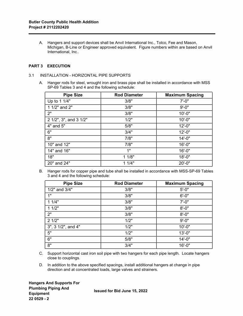
Butler County Public Health Addition Project # 2112202420
Hangers And Supports For Plumbing Piping And Equipment 22 0529 - 2
Issued for Bid June 15, 2022
A. Hangers and support devices shall be Anvil International Inc., Tolco, Fee and Mason, Michigan, B-Line or Engineer approved equivalent. Figure numbers within are based on Anvil International, Inc..
PART 3 EXECUTION
3.1 INSTALLATION - HORIZONTAL PIPE SUPPORTS
A. Hanger rods for steel, wrought iron and brass pipe shall be installed in accordance with MSS SP-69 Tables 3 and 4 and the following schedule:
Pipe Size Rod Diameter Maximum SpacingUp to 1 1/4" 3/8" 7'-0"1 1/2" and 2" 3/8" 9'-0"2" 3/8" 10'-0"2 1/2", 3", and 3 1/2" 1/2" 10'-0"4" and 5" 5/8" 12'-0"6" 3/4" 12'-0"8" 7/8" 14'-0"10" and 12" 7/8" 16'-0"14" and 16" 1" 16'-0"18" 1 1/8" 18'-0"20" and 24" 1 1/4" 20'-0"
B. Hanger rods for copper pipe and tube shall be installed in accordance with MSS-SP-69 Tables 3 and 4 and the following schedule:
Pipe Size Rod Diameter Maximum Spacing1/2" and 3/4" 3/8" 5'-0"1" 3/8" 6'-0"1 1/4" 3/8" 7'-0"1 1/2" 3/8" 8'-0"2" 3/8" 8'-0"2 1/2" 1/2" 9'-0"3", 3 1/2", and 4" 1/2" 10'-0"5" 1/2" 13'-0"6" 5/8" 14'-0"8" 3/4" 16'-0"
C. Support horizontal cast iron soil pipe with two hangers for each pipe length. Locate hangers close to couplings.
D. In addition to the above specified spacings, install additional hangers at change in pipe direction and at concentrated loads, large valves and strainers.
Butler County Public Health Addition Project # 2112202420
Issued for Bid June 15, 2022
Hangers And Supports For Plumbing Piping And
Equipment22 0529 - 3
E. Where more than one pipe is to be run parallel together, they may be supported on trapeze type hangers. Trapeze bar angles and hanger rods shall be of sufficient size to support the particular group of pipes. Trapeze hanger spacing shall be based on the smallest pipe on the rack. When hanging from light gauge metal trusses, coordinate pipe hanger spacing and hanger rod connection points with the truss manufacturer.
F. For suspending hanger rods from brackets attached to walls, use welded steel brackets: Fig. 194 for loads up to 750 lbs; Fig. 195 for loads up to 1500 lbs; Fig. 199 for loads up to 3000 lbs.
G. Where pipes are to be racked along walls, use '' Unistrut'' pipe racks or 12 gauge steel strut channel, 1-5/8" x 1-5/8" minimum.
1. Mount pipes to strut channel with two-piece pipe straps to match outside diameter of pipe including insulation.
H. Attach all pipe hangers from support rods using double locknuts tightened to prevent loosening.
3.2 INSTALLATION - VERTICAL PIPE SUPPORTS
A. Support vertical steel, wrought iron, copper and brass pipe at every other floor line.
B. Support vertical cast iron soil pipe at every floor line.
C. In addition to the above, support vertical pipes at base of riser with base fitting set on concrete or brick pier, or by hanger located on horizontal connection close to riser.
D. Where pipe sleeves extend above floor, place pipe clamps at ceiling below and support clamp extensions from inserts or other approved attachment.
3.3 PIPE ATTACHMENTS
A. For horizontal steel and wrought iron pipe, use carbon steel adjustable clevis hanger, Fig. 260. For floor support or support directly above steel beams, use adjustable pipe roll stand, Fig. 177.
B. For horizontal copper pipe and tube, use copper-plated, carbon steel adjustable swivel ring, Fig. CT-69.
C. When thermal expansion for horizontal pipe is in excess of ½” axially, use adjustable steel yoke pipe roll, Fig. 181, or adjustable pipe roll stand, Fig. 177.
D. For horizontal cast iron soil pipe, use carbon steel adjustable clevis hanger, Fig. 260.
E. For vertical steel, wrought iron and cast iron pipe, use extension pipe or riser clamps, Fig. 261.
F. For vertical copper pipe and tube, use copper-plated, copper plated copper tubing riser pipe clamp, Fig. CT-121.
3.4 INTERMEDIATE ATTACHMENTS
A. Hanger rods: Carbon steel single or double end threaded, Figs. 140, 253 as required. Continuous threaded rod, Fig. 146 may be used wherever possible.
B. Chain wire or perforated strap hangers will not be permitted. One pipe shall not be suspended from another pipe.
3.5 STRUCTURAL ATTACHMENTS
Butler County Public Health Addition Project # 2112202420
Hangers And Supports For Plumbing Piping And Equipment 22 0529 - 4
Issued for Bid June 15, 2022
A. For attaching steel or copper plated hanger rods to reinforced concrete, use galvanized malleable iron universal concrete inserts; Fig. 282 for loads up to 1140 lbs.
B. For attaching steel hanger rods to structural steel beams, use malleable iron C-clamps; Fig. 92, Fig. 93 or Fig. 94 with retaining clip Fig. 89 or Fig. 89X for loads up to 500 lbs; Fig. 218 with extension piece for loads up to 1,365 lbs. For copper plated hanger rods, use copper plated malleable iron C-clamps; Fig. CT-138R for loads up to 180 lbs.
C. For attaching steel hanger rods to wood structural members, use malleable iron ceiling flange; Fig. 153 for loads up to 1,270 lbs. For copper plated hanger rods, use copper plated malleable iron ceiling flange: Fig. CT-128R for loads up to 180 lbs.
D. Vertical expansion shields or toggles shall not be used for suspending hanger rods, except with permission in cases where inserts have been omitted or cannot be used. If permitted, use expansion shields; for rod sizes up to ½”, 320 lbs. max. load. For hanger rods larger than ½” use attachment plate, Fig. 52, with wedge anchors.
E. Powder actuated anchoring methods shall not be used.
3.6 PIPE COVERING PROTECTION
A. Hangers and supports for insulated piping shall not injure or pierce insulation. Provide insulation protection shields in conjunction with hanger or roll device. Use Fig. 160 and 165, Protection Saddles.
3.7 SUPPLEMENTAL STEEL
A. Provide supplemental steel as required to hang or support plumbing equipment or piping.
END OF SECTION 22 0529
Butler County Public Health AdditionProject # 2112202420
Issued for Bid June 15, 2022
Vibration and Seismic Controls for Plumbing Piping and
Equipment22 0548 - 1
SECTION 22 0548 VIBRATION AND SEISMIC CONTROLS FOR PLUMBING PIPING AND EQUIPMENT
PART 1 GENERAL
1.1 SECTION INCLUDES
A. This specification pertains to the furnishing and installation of vibration isolation devices for plumbing piping and rotating or reciprocating mechanical equipment.
B. This work shall include all material and labor required for installation of the resilient mounting and suspension systems, adjusting each mounting system, and measurement of isolator system performance when so requested by the Architect/Engineer. Specific mounting arrangements for each item of mechanical equipment shall be as described herein and as indicated by schedules and details on the drawings.
1.2 QUALIFICATIONS
A. All rotating mechanical equipment shall be isolated from the structure by means of vibration isolators. The isolators and bases shall be as tabulated on the Vibration Isolation Schedule in this section. Any equipment not listed in this schedule shall be isolated with the isolator type and deflection shown in the 2011 ASHRAE HVAC Applications Handbook, Chapter 48, Table 47.
B. Vibration isolators and bases shall be as manufactured by Kinetics Noise Control, Mason Industries, Amber Booth or approved equivalent, and shall all be provided by the mechanical contractor form a single manufacturer to assure single responsibility for the performance of all isolation equipment. The isolator manufacturer's submittal shall include a tabulation of the design data with dimensions for both free and operating heights of the isolators.
C. Engage manufacturer to provide technical supervision of installation of support isolation units produced, and of associated inertia bases.
D. The Contractor and the vibration isolation manufacturer or his regularly designated and factory authorized representative shall perform the following tasks in addition to the supply and installation of isolation equipment:
1. Obtain from the Architect/Engineer the approved manufacturer's name, model number, and other necessary identifying data for each item of mechanical equipment to be resiliently mounted. Coordinate resilient mounting systems with the exact equipment to be furnished in regard to physical size, isolator locations, weight, rotating speed, etc. Direct contact and cooperation between the vibration isolation device fabricator and the equipment manufacturer will be required.
2. Select piping systems isolators for proper coordination with the physical arrangement of pipe lines and with the physical characteristics of the building.
3. Provide on-the-job supervision as required during installation of resiliently mounted equipment and piping to assure that vibration isolators are installed in strict accordance with normally accepted practices for critical environments.
4. Replace, at no extra cost to the Owner, isolators which do not produce the required deflection, are improperly loaded above or below their correct operating height, or which do not produce the required isolation.
Butler County Public Health Addition Project # 2112202420
Vibration and Seismic Controls for Plumbing Piping and Equipment 22 0548 - 2
Issued for Bid June 15, 2022
5. Cooperate with other contractors engaged in this project so that the installation of vibration isolation devices will proceed in a manner that is in the best interests of the Owner.
6. Notify the Architect/Engineer of project conditions which affect vibration isolation system installation of performance and which are found to be different from conditions indicated by the drawings or described by the specifications. Should vibrations isolation system installation proceed without such notifications, remedial work required to achieve proper isolator performance shall be accomplished by the contractor at no additional cost to the Owner.
7. Be alert for possible short-circuiting of vibration isolation systems by piping supports, electrical connections, temperature control connections, drain lines, building construction, etc., and notify the involved contractor as to these problems or potential problems. Where such situations cannot be easily resolved, notify the Architect/Engineer so that preventive or remedial action can take place on a timely basis. Remedial measures required shall be undertaken by the contractor responsible at no additional cost to the Owner.
E. Vibration isolation products furnished as part of factory-fabricated equipment are specified as part of the equipment assembly in other Division 22 sections.
F. Refer to other sections of these specifications for equipment foundations, hangers, sealants, gaskets and other work related to vibration isolation work.
G. Where equipment manufacturer's recommendations differ from specified vibration isolation, submit to Architect for review and approval.
H. Furnish templates to fabricators of equipment bases, foundations and other support systems, as needed for coordination of vibration isolation units with other work.
1.3 SUBMITTALS
A. Product Data: Submit manufacturer's specifications, detailed drawings, performance characteristic data and installation instructions for each type of unit required. Indicate equipment to be installed with isolator, tabulation of design data with dimensions for both free and operating heights of isolators, and load on each.
1.4 PERFORMANCE REQUIREMENTS
A. Seismic-Restraint Loading:
1. Site Class as Defined in the IBC: A.
PART 2 PRODUCTS
2.1 GENERAL
A. The vibration isolation systems described herein and identified by type number designations shall be applied to specific classifications of mechanical equipment as indicated in the Vibration Isolation Schedule.
2.2 TYPE 1 ISOLATORS (RUBBER & GLASS FIBER PADS AND HANGERS)
A. Pre-compressed Molded Fiberglass Vibration Isolation Pads, individually coated with a flexible moisture impervious elastomeric membrane. Pads shall be fine (.00018 dia.) bonded annealed
Butler County Public Health Addition Project # 2112202420
Issued for Bid June 15, 2022
Vibration and Seismic Controls for Plumbing Piping and
Equipment22 0548 - 3
glass fibers which have been stabilized during manufacture by overloading the material ten times. Pads shall have a constant natural frequency over the operating load range, and the stiffness shall increase proportionately with load applied. Pads shall be no taller than the shortest horizontal dimension. Where the equipment base does not provide a uniform load surface, steel plates shall be bonded to the top of the pads. Alternately, Neoprene Mounts incorporating completely enclosed metal inserts to permit bolting the supported unit may be used.
2.3 TYPE 2 ISOLATORS (PAD AND HANGER TYPE)
A. Molded isolators shall come in a range of 30 to 70 durometer and shall be designed for up to ½" deflection.
B. Hangers shall be designed for a 20° to 35° misalignment.
2.4 TYPE 3 ISOLATORS (SPRINGS)
A. Freestanding, Un-housed, laterally stable steel springs with leveling bolts and ¼-in. thick ribbed isolation pads. To assure stability, the spring shall have a lateral spring stiffness equal to the rated vertical stiffness, and shall be designed to provide 50% overload capacity. In capacities up to 5,000 lbs., springs shall be replaceable. In capacities over 5,000 lbs., springs shall be welded to the top and bottom load plate assemblies.
B. Combination Spring and Rubber Hangers. The pre-compressed fiberglass shall be coated with a moisture impervious elastomeric membrane in series with springs, all encased in welded steel brackets. Springs shall be as specified for Type 3 isolators. Hangers shall be designed for 50% overload capacity, and shall accommodate rod misalignment over a 30° arc. Brackets shall be designed to carry 500% overload without failure.
2.5 TYPE 4 ISOLATORS
A. Freestanding, Laterally Stable Spring Isolators with vertical limit stops to assure a constant operating height if the supported weight is removed, and to reduce movement due to wind loads. Limit stops shall be isolated from the housing to prevent short-circuiting.
2.6 TYPE A BASES
A. No base required. Isolators may be attached directly to the supported equipment.
2.7 TYPE D BASES
A. Roof Curb Isolators: Fabricated frame units sized to match roof curbs as shown, formed with isolation springs between extruded aluminum upper and lower sections, which are shaped and positioned to prevent metal-to-metal contact. Provide continuous airtight and waterproof seal between upper and lower extrusions. Include provisions for anchorage of frame unit to roof curb, and for anchorage of equipment to unit. Equivalent to Mason Type CMAB or RSC as required.
2.8 PIPING ISOLATION
A. Piping over 1 in. diameter in mechanical equipment rooms, and piping three supports away from other mechanical equipment shall be isolated from the structure by means of vibration and noise isolators.
B. Suspended piping shall be isolated with Type 3 Hangers.

Butler County Public Health Addition Project # 2112202420
Vibration and Seismic Controls for Plumbing Piping and Equipment 22 0548 - 4
Issued for Bid June 15, 2022
C. Floor mounted piping shall be isolated with Type 3 Isolators.
D. Flexible members shall be incorporated in the piping adjacent to all equipment housing pipe connections.
2.9 PUMP CONNECTORS
A. Provide flexible connectors at suction and discharge of circulating pumps.
B. Pipe connectors shall be 18 in. for pipe sizes 6 in. and larger, and 12 in. for smaller pipes.
C. Pipe connectors shall be of Butyl rubber material with reinforced carcasses and integral rubber and threaded flanges. Connectors shall be suitable for 200-degree water at 150 psi working pressure.
D. Protection against elongation shall be provided by tie rod control units with rubber grommets.
E. Pipe connectors shall be Type 150 B with split galvanized retaining ring as manufactured by Mercer or approved equivalent.
2.10 ELECTRICAL CONNECTIONS TO RESILIENTLY MOUNTED EQUIPMENT
A. Electrical connections to equipment which is supported or suspended by vibration isolators shall be made with long lengths of flexible conduit or flexible armored cable. These flexible connections must be located so as to prevent rigid conduit connections between the resiliently mounted equipment and the building structure.
PART 3 INSTALLATION
3.1 EXECUTION
A. General: Except as otherwise indicated, comply with manufacturer's instructions for the installation and load application to vibration isolation materials and units. Adjust to ensure that units do not exceed rated operating deflections or bottom out under loading, and are not short-circuited by other contacts or bearing points. Remove space blocks and similar devices (if any) intended for temporary protection against overloading during installation.
B. Anchor and attach units to substrate and equipment as required for secure operation and to prevent displacement by normal forces, and as indicated.
C. Adjust leveling devices as required to distribute loading uniformly onto isolators. Shim units as required where leveling devices cannot be used to distribute loading properly.
D. Flexible Pipe Connectors: Refer to other section of these Specifications for the installation of flexible pipe connectors.
E. Install vibration isolators that are furnished with equipment.
END OF SECTION 22 0548
Butler County Public Health AdditionProject # 2112202420
Issued for Bid June 15, 2022 Identification for Plumbing
Piping and Equipment22 0553 - 1
SECTION 22 0553 IDENTIFICATION FOR PLUMBING PIPING AND EQUIPMENT
PART 1 GENERAL
1.1 SECTION INCLUDES
A. Provide materials, equipment labor and supervision necessary to install piping identification products.
B. Comply with ANSI A13.1 for lettering size, length or color field, colors, and installed viewing angles of identification devices.
1.2 REFERENCE STANDARDS
A. ASME A13.1 - Scheme for the Identification of Piping Systems; The American Society of Mechanical Engineers; 2007.
B. ASTM D709 - Standard Specification for Laminated Thermosetting Materials; 2013.
1.3 SUBMITTALS
A. Submit manufacturer's product data.
B. Submit sample of each type of identification product and clearly identify the contents in a schedule.
C. List: Submit list of wording, symbols, letter size, and color coding for mechanical identification.
D. Schedule:
1. Submit valve schedule for each system, typewritten and reproduced on 8-1/2" x 11" bond paper. Tabulate valve ID tag number, system, system abbreviation (as shown on tag), location of valve (room or space), and variations for identification (if any). Mark valves that are intended for emergency shut-off and similar special uses, by special "flags" in margin of schedule.
PART 2 PRODUCTS
2.1 MANUFACTURERS
A. Brady Corp., Industrial Safety Supply, Emedco, Seton or Brimar.
B. Engineer approved alternative
2.2 PIPE MARKERS
A. Provide manufacturer's standard preprinted, semi-rigid snap-on or self-sticking, color-coded pipe markers, complying with ANSI A13.1.
B. Provide full-band pipe markers, extending 360° around pipe at each location or self-sticking pipe markers, fastened in the following method:
1. Snap-on application of pre-tensioned semi-rigid plastic pipe marker.2. Secure to piping and install banding tape on both ends of each pipe label.
Butler County Public Health Addition Project # 2112202420
Identification for Plumbing Piping and Equipment 22 0553 - 2
Issued for Bid June 15, 2022
C. Lettering shall be manufacturer's pre-printed nomenclature which best describes piping system in each instance, as selected by Architect/Engineer in cases of variance.
D. Print each pipe marker with arrows indicating direction of flow, integrally with piping system service lettering (to accommodate both directions), or as separate unit of plastic or on banding tape.
2.3 EQUIPMENT MARKERS
A. Provide engraved signage nameplates and tags constructed of multi-layered acrylic that has been treated for outdoor use and can withstand temperatures up to 160° F. Nameplates shall have beveled edges with contrasting color core, letters, and border. Minimum size of nameplate shall be 3" high by 6" long. The minimum letter height shall be 3/4". Attachment shall be by double faced 2 mil permanent acrylic adhesive. For equipment that doesn't allow for direct attachment, furnish sheet metal backing to integrate with equipment such that signage can be read from 5 feet above the finished floor. Unless noted otherwise, signage shall be provided with black lettering, black border, and yellow core. All signage shall include up to 14 characters per line, minimum of 3 lines per tag. Furnish signage for equipment shown in Section 3:
1. All pumps shall include the full name description for system served such as "Primary Chilled Water Pump – 1."
B. All equipment shall be named consistent with the plans and specifications as indicated on the schedules or as directed by the Owner.
2.4 BRASS VALVE TAGS
A. Provide manufacturer's standard brass valve tags with stamped black filled lettering, with piping system abbreviation in 1/4" high letters and sequenced valve numbers 1/2" high, and with 3/16" hole for fastener.
B. Provide 1-1/2" round brass tags with black lettering. Seton 250 BL or equal.
2.5 VALVE TAG FASTENERS
A. Manufacturer's standard solid brass chain or solid brass S-hooks of sizes required for proper attachment of tags to valves and manufactured specifically for that purpose.
2.6 VALVE SCHEDULE FRAMES
A. For each page of schedule, provide glazed display frame, with screws for removable mounting on masonry walls. Provide frames of finished hardwood or extruded aluminum, with SSD-grade sheet glass.
2.7 PIPING AND EQUIPMENT IDENTIFICATION
A. Piping systems that shall be identified by their controls (including directional arrows) on this project shall include, but are not necessarily limited to the following:
1. Domestic cold water, hot water, and hot water recirculation.2. Sanitary and sanitary vent.
B. Provide name plates for all equipment scheduled on the drawings. Coordinate nameplate tag with Owner's sequencing system. If the Owner has no preference, the nameplates shall correspond with the equipment schedule. Equipment shall include but is not limited to the following:
Butler County Public Health Addition Project # 2112202420
Issued for Bid June 15, 2022 Identification for Plumbing
Piping and Equipment22 0553 - 3
1. Air separators.2. Pumps.3. Expansion tanks.4. Water heaters.5. Tanks
PART 3 EXECUTION
3.1 INSTALLATION OF MECHANICAL IDENTIFICATION
A. Where identification is to be applied to surfaces that require insulation, painting or other covering or finish, including valve tags in finished mechanical spaces, install identification after completion of covering and painting. Install identification prior to installation of acoustical ceilings and similar removable concealment.
B. Install pipe markers on each system, and include arrows to show normal direction of flow.
C. Locate pipe markers as follows: wherever piping is exposed to view in occupied spaces, machine rooms, accessible maintenance spaces (shafts, tunnels, plenums) above lay-in type ceilings and exterior non-concealed locations.
1. Near each valve and control device.2. Near each branch, excluding short take-offs for fixtures, mark each pipe at branch where
there could be question of flow pattern.3. Near locations where pipes pass through walls or floors/ceilings, (both sides) or center
non-accessible enclosures.4. At access doors, manholes, and similar access points that permit view of concealed
piping.5. Near major equipment items and other points of origination and termination.6. At each pipe passage to underground.7. Spaced intermediately at maximum spacing of 50 feet along each piping run, except
reduce spacing to 25 feet in congested areas of piping and equipment.8. On piping above removable acoustical ceilings, maximum spacing of 10 feet along each
piping run.9. Where self-sticking labels are used, the pipe or its covering surface shall be properly
prepared. This consists of removal of loose dirt, oil and grease, loose paint or peeling insulation covering. This can be done with a brush and cloth; washing is not required. Use solvent for removal of oil or grease.
10. Banding tape must be used on both ends of all self-sticking labels. The tape shall encircle the pipe completely and overlap itself so the banding tape can adhere to itself.
D. Provide valve tags for all major valves 1/2" size or larger. Included are all main, zone and branch valves, valves in all equipment rooms, etc. All types of valves, ball, globe, butterfly, cocks, control, regulating, relief, reducing, solenoid, etc. are to be identified except check valves. Do not identify end use point valves for plumbing fixtures, and similar rough-in connections.
E. List each tagged valve in schedule for each system showing function and location. Provide separate charts for mechanical divisions of work. Charts shall be installed on a conspicuous
Butler County Public Health Addition Project # 2112202420
Identification for Plumbing Piping and Equipment 22 0553 - 4
Issued for Bid June 15, 2022
wall in the main mechanical equipment room. Provide unframed copies of valve lists as part of closeout documents.
3.2 ADJUSTING AND CLEANING
A. Relocate any mechanical identification device which has become visually blocked by work of this division or by other divisions.
B. Clean face of identification devices and glass frames of valve schedules.
END OF SECTION 22 0553
Butler County Public Health AdditionProject # 2112202420
Issued for Bid June 15, 2022 Plumbing Insulation22 0700 - 1
SECTION 22 0700 PLUMBING INSULATION
PART 1 GENERAL
1.1 SECTION INCLUDES
A. Provide equipment, materials, labor and supervision necessary to install insulation to hot and cold surfaces of piping, tanks, ductwork, fittings and other surfaces.
B. Insulation shall include insulating materials, jackets, adhesive, mastic coatings, tie wire and other materials as required to complete the insulating work.
1.2 CODES AND STANDARDS
A. Insulating materials, jackets and mastics shall meet flame spread, fuel contribution and smoke developed ratings in accordance with NFPA-90A. Flame spread rating in accordance with NFPA 255, ASTM E-84, or UL 723 of not more than 25; smoke developed rating of not more than 50, unless otherwise noted in this section.
B. Insulation that has been treated with a flame-retardant additive to meet the flame spread and smoke developed ratings shown above is not permitted.
C. Insulation materials shall be non-corrosive to the materials they are applied to, including stress corrosion cracking of stainless steel and shall not breed or promote mold, fungus or bacteria.
D. Insulation shall meet or exceed all requirements of ASHRAE/IES 90.1 - Energy Standard for Buildings Except Low-Rise Residential Buildings .
1.3 QUALIFICATION
A. Insulating materials by Owens-Corning, Armacell, Pittsburgh-Corning, Knauf, Johns Manville, or Engineer approved equivalent.
B. Mastics and adhesives as recommended by insulation manufacturer.
1.4 SUBMITTALS
A. Product Data: Submit manufacturer's technical product data and installation instructions for each type of mechanical insulation and jacket. Submit schedule showing manufacturer's product number, flame spread and smoke development rating, k-value, density, temperature limitations, sound absorption coefficients, thickness, and furnished accessories for each mechanical system requiring insulation.
PART 2 PRODUCTS
2.1 INSULATION
A. Description:
1. Type A: Preformed, sectional, heavy density fiberglass insulation, suitable for operating temperatures form - 20 F to +850 F. Equipped with factory-applied, all-service vapor barrier jacket constructed of white Kraft paper bonded to aluminum foil reinforced with fiberglass yarn, with pressure-sensitive, self-sealing longitudinal laps and butt strips. Thermal conductivity of 0.23 BTU-in/hr-ft2- F @ 75 F mean temperature. Water
Butler County Public Health Addition Project # 2112202420
Plumbing Insulation 22 0700 - 2 Issued for Bid June 15, 2022
vapor permeance of 0.02 perms. Johns Manville "Micro-Lok HP or Engineer approved equivalent.
2. Type B: Flexible, elastomeric pipe and sheet insulation with closed-cell structure. Shall comply with ASTM C534, Type I, Grade 1 for tubular materials and ASTM C534 Type II, Grade 1 for sheet materials. Suitable for operating temperatures from –40° F to 220° F. Outdoor applications, and where otherwise noted, shall receive a weather-resistant, protective, latex enamel finish. Thermal conductivity of 0.28 BTU-in/hr-ft2-°F @ 75° F mean temperature. Water vapor permeance of 0.08 perms. Insulation shall be equivalent to Armacell AP Armaflex; adhesive equivalent to Armacell Armaflex 520 or Armaflex 520 BLV Low-VOC Contact Adhesive; finish equivalent to Armacell Armaflex WB finish.
3. Type C: Flexible, elastomeric thermal insulation with an expanded, closed-cell structure. Pre-slit tubular form with a pressure-sensitive adhesive strip for closure and vapor sealing of the longitudinal joint. Butt joints, sealed with 3M-471 tape. White color. Suitable for operating temperature of 40 F to 200 F. Thermal conductivity of 0.28 BTU-in/hr-ft2- F mean temperature. Water vapor permeance of 0.20 perms. Insulation shall be Armacell Self-Seal Armaflex 2000 or Engineer approved equivalent.
4. Type D: Preformed, rigid, expanded, 90% closed-cell polyisocyanurate suitable for operating temperatures of - 320 F to +300 F. Equipped with factory applied, all-service vapor barrier jacket constructed of white Kraft paper bonded to aluminum foil reinforced with fiberglass yarn, with pressure-sensitive, self-sealing longitudinal laps and butt strips. Thermal conductivity for aged material of 0.18 BTU-in/hr-ft2- F @ 75 F mean temperature. Water vapor permeance of 0.02 perms. Thermacor "CTI" or Engineer approved equivalent.
5. Type E: Preformed, rigid, cellular glass for operating temperature of - 290 F to +1000 F. Thermal conductivity of 0.35 BTU-in/hr-ft2- F @ 75 F mean temperature. Water vapor permeance of 0.00 perms. Pittsburgh-Corning "FOAMGLAS" or Engineer approved equivalent.
6. Type F: Hydrous calcium silicate, premolded, asbestos-mercury-lead-free, suitable for applications up to 1200 F. Thermal conductivity of 0.437 BTU-in/hr-ft2- F @ 300 F mean temperature per ASTM C335. Insulation shall have low chloride content such that it will not cause or promote stress corrosion cracking of stainless steel. Johns Manville "Thermo-12 Gold" or Engineer approved equivalent.
7. Type G: Semi-rigid fiberglass blanket with factory applied foil Skrim-Kraft (FSK) suitable for operating temperature of - 20 F to +650 F. Thermal conductivity of 0.27 BTU-in/hr-ft2- F @ 75 F mean temperature. Water vapor permeance of 0.02 perms. Knauf "Pipe and Tank" insulation or Engineer approved equivalent.
2.2 PIPE INSULATION SCHEDULE
SERVICE TYPE THICKNESS PIPE SIZES
DOMESTIC COLD A,B,C 1/2" LESS THAN 1-1/2" WATER 1-1/2" AND LARGER
DOMESTIC HOT WATER A,B,C 1" LESS THAN 1-1/2" (UP TO 140 DEG F) 1-1/2" 1-1/2" AND LARGER INCLUDING HW CIRC.
COLD CONDENSATE A,B,C 1/2" ALL SIZES DRAINS
HORIZONTAL STORM A,B,C 1" ALL SIZES DRAINAGE
ALL EXPOSED STORM A,B,C 1" ALL SIZES DRAIN PIPING
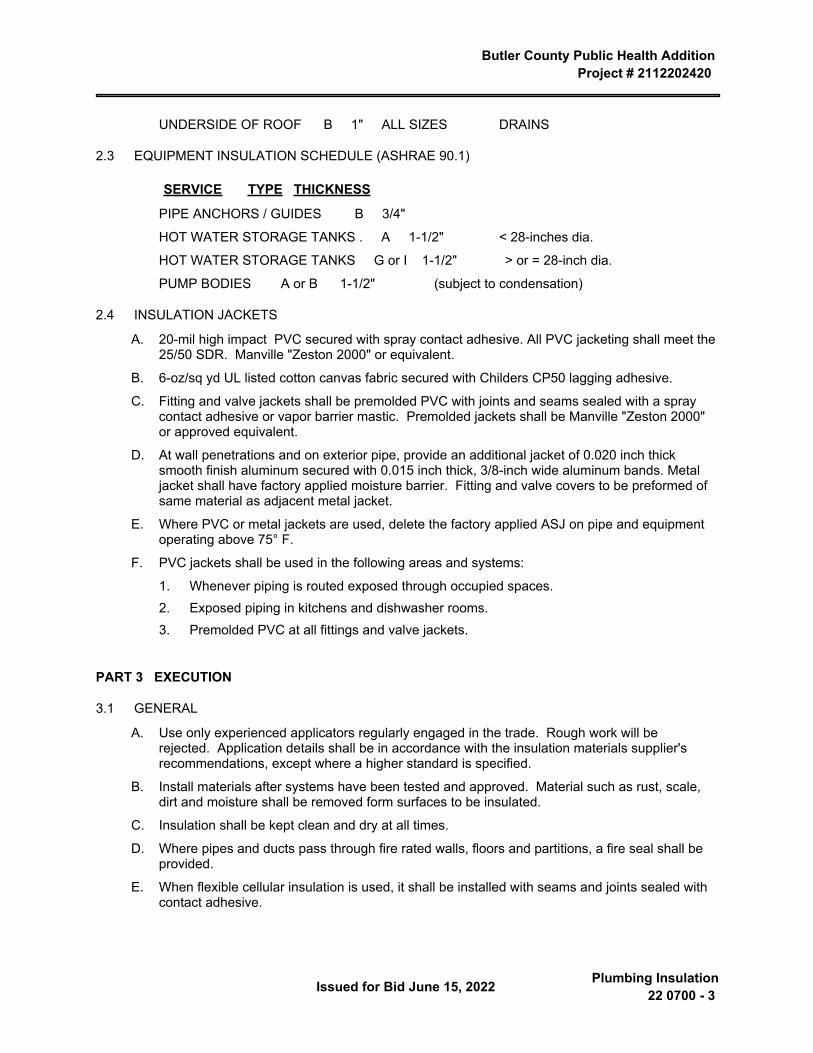
Butler County Public Health Addition Project # 2112202420
Issued for Bid June 15, 2022 Plumbing Insulation22 0700 - 3
UNDERSIDE OF ROOF B 1" ALL SIZES DRAINS
2.3 EQUIPMENT INSULATION SCHEDULE (ASHRAE 90.1)
SERVICE TYPE THICKNESS
PIPE ANCHORS / GUIDES B 3/4"
HOT WATER STORAGE TANKS . A 1-1/2" < 28-inches dia.
HOT WATER STORAGE TANKS G or I 1-1/2" > or = 28-inch dia.
PUMP BODIES A or B 1-1/2" (subject to condensation)
2.4 INSULATION JACKETS
A. 20-mil high impact PVC secured with spray contact adhesive. All PVC jacketing shall meet the 25/50 SDR. Manville "Zeston 2000" or equivalent.
B. 6-oz/sq yd UL listed cotton canvas fabric secured with Childers CP50 lagging adhesive.
C. Fitting and valve jackets shall be premolded PVC with joints and seams sealed with a spray contact adhesive or vapor barrier mastic. Premolded jackets shall be Manville "Zeston 2000" or approved equivalent.
D. At wall penetrations and on exterior pipe, provide an additional jacket of 0.020 inch thick smooth finish aluminum secured with 0.015 inch thick, 3/8-inch wide aluminum bands. Metal jacket shall have factory applied moisture barrier. Fitting and valve covers to be preformed of same material as adjacent metal jacket.
E. Where PVC or metal jackets are used, delete the factory applied ASJ on pipe and equipment operating above 75° F.
F. PVC jackets shall be used in the following areas and systems:
1. Whenever piping is routed exposed through occupied spaces.2. Exposed piping in kitchens and dishwasher rooms.3. Premolded PVC at all fittings and valve jackets.
PART 3 EXECUTION
3.1 GENERAL
A. Use only experienced applicators regularly engaged in the trade. Rough work will be rejected. Application details shall be in accordance with the insulation materials supplier's recommendations, except where a higher standard is specified.
B. Install materials after systems have been tested and approved. Material such as rust, scale, dirt and moisture shall be removed form surfaces to be insulated.
C. Insulation shall be kept clean and dry at all times.
D. Where pipes and ducts pass through fire rated walls, floors and partitions, a fire seal shall be provided.
E. When flexible cellular insulation is used, it shall be installed with seams and joints sealed with contact adhesive.
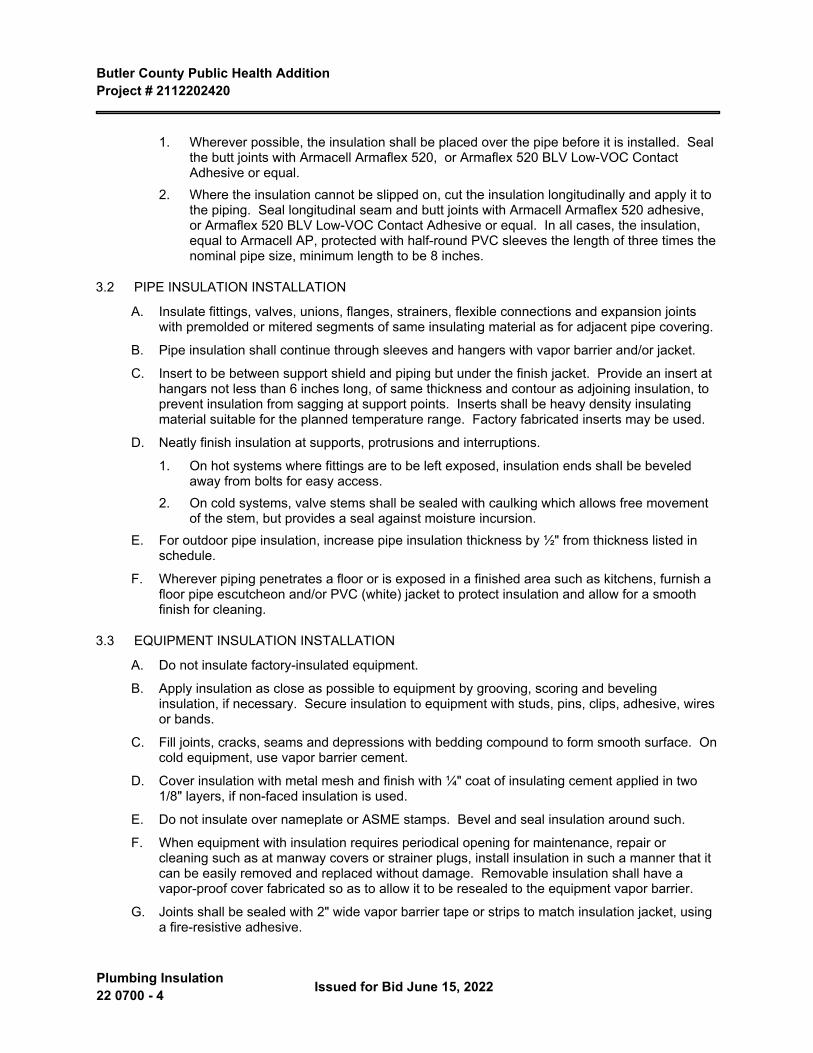
Butler County Public Health Addition Project # 2112202420
Plumbing Insulation 22 0700 - 4 Issued for Bid June 15, 2022
1. Wherever possible, the insulation shall be placed over the pipe before it is installed. Seal the butt joints with Armacell Armaflex 520, or Armaflex 520 BLV Low-VOC Contact Adhesive or equal.
2. Where the insulation cannot be slipped on, cut the insulation longitudinally and apply it to the piping. Seal longitudinal seam and butt joints with Armacell Armaflex 520 adhesive, or Armaflex 520 BLV Low-VOC Contact Adhesive or equal. In all cases, the insulation, equal to Armacell AP, protected with half-round PVC sleeves the length of three times the nominal pipe size, minimum length to be 8 inches.
3.2 PIPE INSULATION INSTALLATION
A. Insulate fittings, valves, unions, flanges, strainers, flexible connections and expansion joints with premolded or mitered segments of same insulating material as for adjacent pipe covering.
B. Pipe insulation shall continue through sleeves and hangers with vapor barrier and/or jacket.
C. Insert to be between support shield and piping but under the finish jacket. Provide an insert at hangars not less than 6 inches long, of same thickness and contour as adjoining insulation, to prevent insulation from sagging at support points. Inserts shall be heavy density insulating material suitable for the planned temperature range. Factory fabricated inserts may be used.
D. Neatly finish insulation at supports, protrusions and interruptions.
1. On hot systems where fittings are to be left exposed, insulation ends shall be beveled away from bolts for easy access.
2. On cold systems, valve stems shall be sealed with caulking which allows free movement of the stem, but provides a seal against moisture incursion.
E. For outdoor pipe insulation, increase pipe insulation thickness by ½" from thickness listed in schedule.
F. Wherever piping penetrates a floor or is exposed in a finished area such as kitchens, furnish a floor pipe escutcheon and/or PVC (white) jacket to protect insulation and allow for a smooth finish for cleaning.
3.3 EQUIPMENT INSULATION INSTALLATION
A. Do not insulate factory-insulated equipment.
B. Apply insulation as close as possible to equipment by grooving, scoring and beveling insulation, if necessary. Secure insulation to equipment with studs, pins, clips, adhesive, wires or bands.
C. Fill joints, cracks, seams and depressions with bedding compound to form smooth surface. On cold equipment, use vapor barrier cement.
D. Cover insulation with metal mesh and finish with ¼" coat of insulating cement applied in two 1/8" layers, if non-faced insulation is used.
E. Do not insulate over nameplate or ASME stamps. Bevel and seal insulation around such.
F. When equipment with insulation requires periodical opening for maintenance, repair or cleaning such as at manway covers or strainer plugs, install insulation in such a manner that it can be easily removed and replaced without damage. Removable insulation shall have a vapor-proof cover fabricated so as to allow it to be resealed to the equipment vapor barrier.
G. Joints shall be sealed with 2" wide vapor barrier tape or strips to match insulation jacket, using a fire-resistive adhesive.

Butler County Public Health Addition Project # 2112202420
Issued for Bid June 15, 2022 Plumbing Insulation22 0700 - 5
END OF SECTION 22 0700

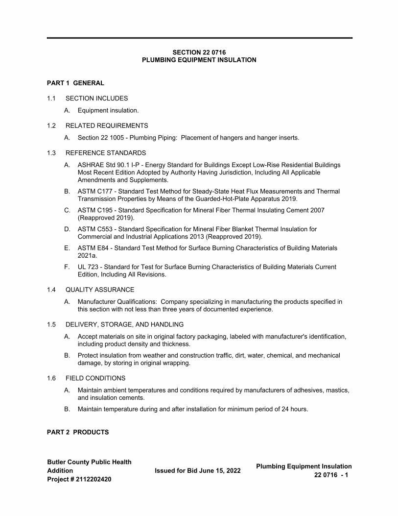
Butler County Public Health AdditionProject # 2112202420
Issued for Bid June 15, 2022 Plumbing Equipment Insulation22 0716 - 1
SECTION 22 0716 PLUMBING EQUIPMENT INSULATION
PART 1 GENERAL
1.1 SECTION INCLUDES
A. Equipment insulation.
1.2 RELATED REQUIREMENTS
A. Section 22 1005 - Plumbing Piping: Placement of hangers and hanger inserts.
1.3 REFERENCE STANDARDS
A. ASHRAE Std 90.1 I-P - Energy Standard for Buildings Except Low-Rise Residential Buildings Most Recent Edition Adopted by Authority Having Jurisdiction, Including All Applicable Amendments and Supplements.
B. ASTM C177 - Standard Test Method for Steady-State Heat Flux Measurements and Thermal Transmission Properties by Means of the Guarded-Hot-Plate Apparatus 2019.
C. ASTM C195 - Standard Specification for Mineral Fiber Thermal Insulating Cement 2007 (Reapproved 2019).
D. ASTM C553 - Standard Specification for Mineral Fiber Blanket Thermal Insulation for Commercial and Industrial Applications 2013 (Reapproved 2019).
E. ASTM E84 - Standard Test Method for Surface Burning Characteristics of Building Materials 2021a.
F. UL 723 - Standard for Test for Surface Burning Characteristics of Building Materials Current Edition, Including All Revisions.
1.4 QUALITY ASSURANCE
A. Manufacturer Qualifications: Company specializing in manufacturing the products specified in this section with not less than three years of documented experience.
1.5 DELIVERY, STORAGE, AND HANDLING
A. Accept materials on site in original factory packaging, labeled with manufacturer's identification, including product density and thickness.
B. Protect insulation from weather and construction traffic, dirt, water, chemical, and mechanical damage, by storing in original wrapping.
1.6 FIELD CONDITIONS
A. Maintain ambient temperatures and conditions required by manufacturers of adhesives, mastics, and insulation cements.
B. Maintain temperature during and after installation for minimum period of 24 hours.
PART 2 PRODUCTS
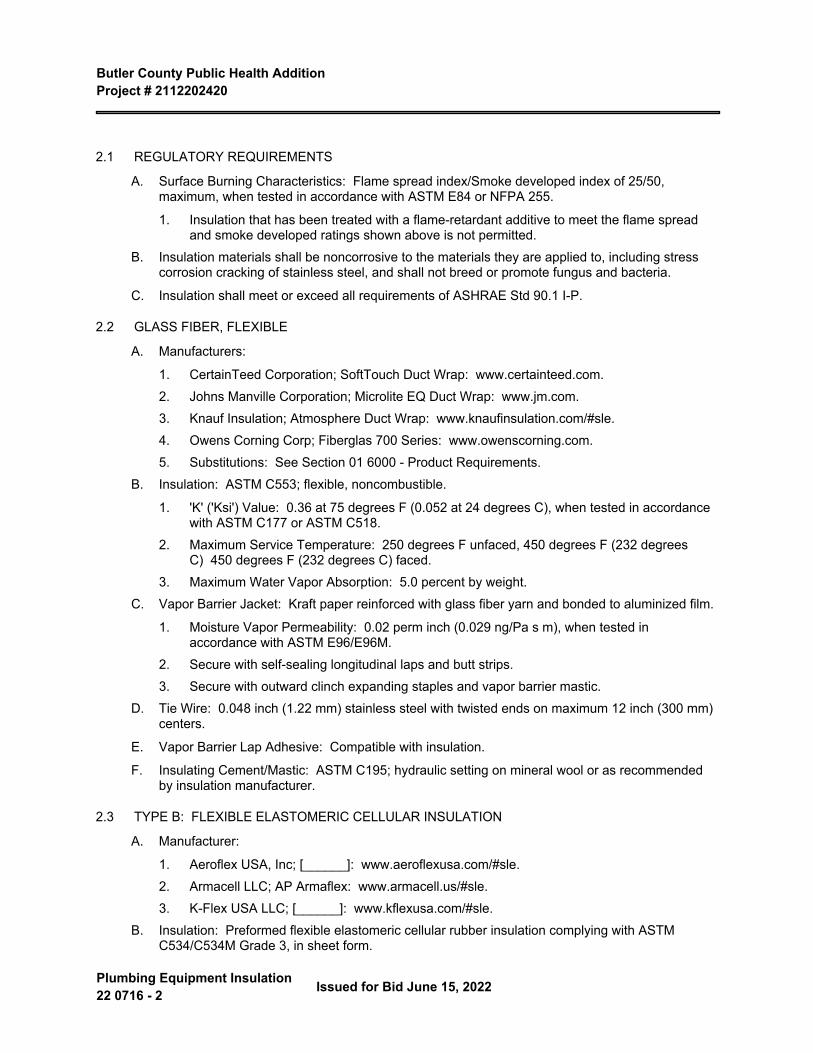
Butler County Public Health Addition Project # 2112202420
Plumbing Equipment Insulation 22 0716 - 2 Issued for Bid June 15, 2022
2.1 REGULATORY REQUIREMENTS
A. Surface Burning Characteristics: Flame spread index/Smoke developed index of 25/50, maximum, when tested in accordance with ASTM E84 or NFPA 255.
1. Insulation that has been treated with a flame-retardant additive to meet the flame spread and smoke developed ratings shown above is not permitted.
B. Insulation materials shall be noncorrosive to the materials they are applied to, including stress corrosion cracking of stainless steel, and shall not breed or promote fungus and bacteria.
C. Insulation shall meet or exceed all requirements of ASHRAE Std 90.1 I-P.
2.2 GLASS FIBER, FLEXIBLE
A. Manufacturers:
1. CertainTeed Corporation; SoftTouch Duct Wrap: www.certainteed.com.2. Johns Manville Corporation; Microlite EQ Duct Wrap: www.jm.com.3. Knauf Insulation; Atmosphere Duct Wrap: www.knaufinsulation.com/#sle.4. Owens Corning Corp; Fiberglas 700 Series: www.owenscorning.com.5. Substitutions: See Section 01 6000 - Product Requirements.
B. Insulation: ASTM C553; flexible, noncombustible.
1. 'K' ('Ksi') Value: 0.36 at 75 degrees F (0.052 at 24 degrees C), when tested in accordance with ASTM C177 or ASTM C518.
2. Maximum Service Temperature: 250 degrees F unfaced, 450 degrees F (232 degrees C) 450 degrees F (232 degrees C) faced.
3. Maximum Water Vapor Absorption: 5.0 percent by weight.C. Vapor Barrier Jacket: Kraft paper reinforced with glass fiber yarn and bonded to aluminized film.
1. Moisture Vapor Permeability: 0.02 perm inch (0.029 ng/Pa s m), when tested in accordance with ASTM E96/E96M.
2. Secure with self-sealing longitudinal laps and butt strips.3. Secure with outward clinch expanding staples and vapor barrier mastic.
D. Tie Wire: 0.048 inch (1.22 mm) stainless steel with twisted ends on maximum 12 inch (300 mm) centers.
E. Vapor Barrier Lap Adhesive: Compatible with insulation.
F. Insulating Cement/Mastic: ASTM C195; hydraulic setting on mineral wool or as recommended by insulation manufacturer.
2.3 TYPE B: FLEXIBLE ELASTOMERIC CELLULAR INSULATION
A. Manufacturer:
1. Aeroflex USA, Inc; [______]: www.aeroflexusa.com/#sle.2. Armacell LLC; AP Armaflex: www.armacell.us/#sle.3. K-Flex USA LLC; [______]: www.kflexusa.com/#sle.
B. Insulation: Preformed flexible elastomeric cellular rubber insulation complying with ASTM C534/C534M Grade 3, in sheet form.
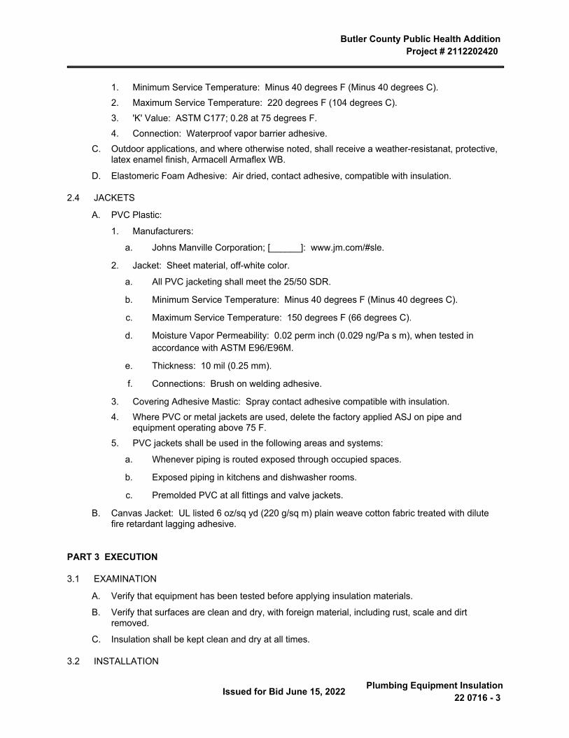
Butler County Public Health Addition Project # 2112202420
Issued for Bid June 15, 2022 Plumbing Equipment Insulation22 0716 - 3
1. Minimum Service Temperature: Minus 40 degrees F (Minus 40 degrees C).2. Maximum Service Temperature: 220 degrees F (104 degrees C).3. 'K' Value: ASTM C177; 0.28 at 75 degrees F.4. Connection: Waterproof vapor barrier adhesive.
C. Outdoor applications, and where otherwise noted, shall receive a weather-resistanat, protective, latex enamel finish, Armacell Armaflex WB.
D. Elastomeric Foam Adhesive: Air dried, contact adhesive, compatible with insulation.
2.4 JACKETS
A. PVC Plastic:
1. Manufacturers:
a. Johns Manville Corporation; [______]: www.jm.com/#sle.
2. Jacket: Sheet material, off-white color.
a. All PVC jacketing shall meet the 25/50 SDR.
b. Minimum Service Temperature: Minus 40 degrees F (Minus 40 degrees C).
c. Maximum Service Temperature: 150 degrees F (66 degrees C).
d. Moisture Vapor Permeability: 0.02 perm inch (0.029 ng/Pa s m), when tested in accordance with ASTM E96/E96M.
e. Thickness: 10 mil (0.25 mm).
f. Connections: Brush on welding adhesive.
3. Covering Adhesive Mastic: Spray contact adhesive compatible with insulation.4. Where PVC or metal jackets are used, delete the factory applied ASJ on pipe and
equipment operating above 75 F.5. PVC jackets shall be used in the following areas and systems:
a. Whenever piping is routed exposed through occupied spaces.
b. Exposed piping in kitchens and dishwasher rooms.
c. Premolded PVC at all fittings and valve jackets.
B. Canvas Jacket: UL listed 6 oz/sq yd (220 g/sq m) plain weave cotton fabric treated with dilute fire retardant lagging adhesive.
PART 3 EXECUTION
3.1 EXAMINATION
A. Verify that equipment has been tested before applying insulation materials.
B. Verify that surfaces are clean and dry, with foreign material, including rust, scale and dirt removed.
C. Insulation shall be kept clean and dry at all times.
3.2 INSTALLATION
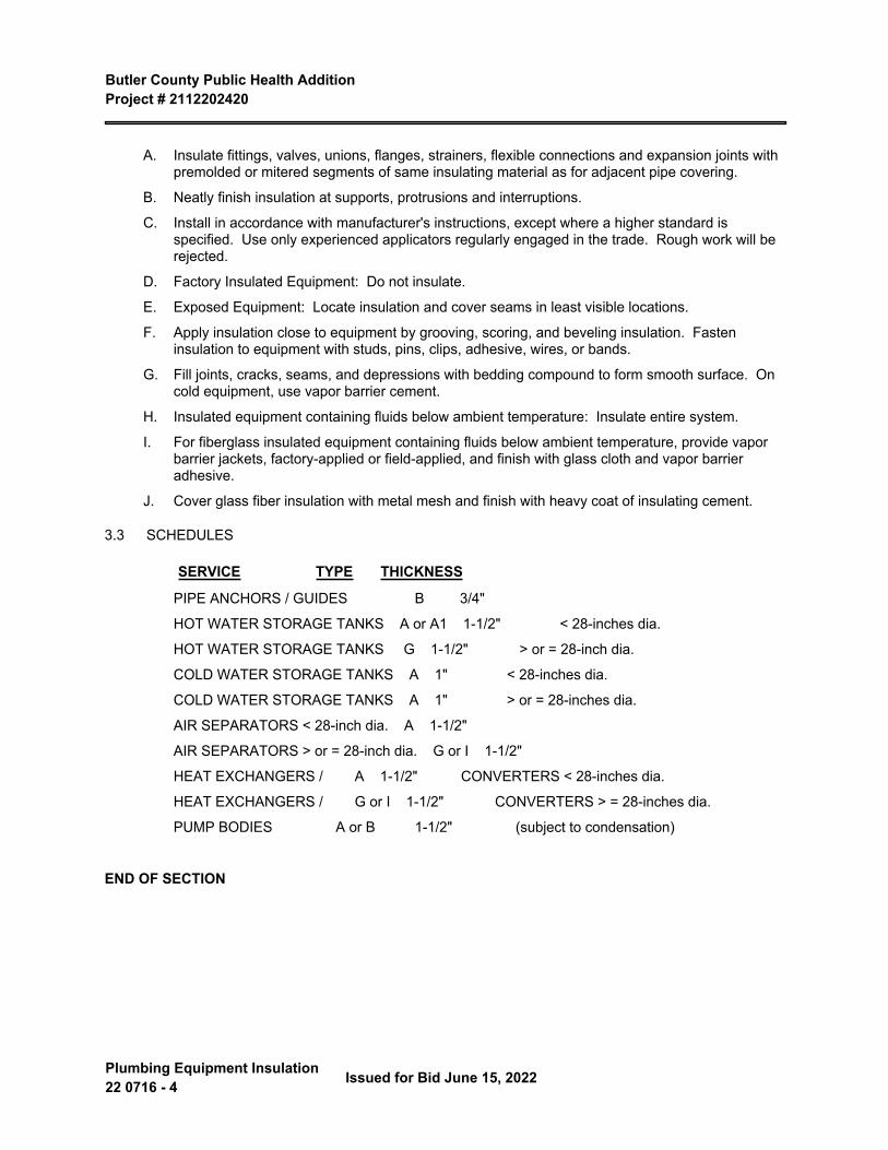
Butler County Public Health Addition Project # 2112202420
Plumbing Equipment Insulation 22 0716 - 4 Issued for Bid June 15, 2022
A. Insulate fittings, valves, unions, flanges, strainers, flexible connections and expansion joints with premolded or mitered segments of same insulating material as for adjacent pipe covering.
B. Neatly finish insulation at supports, protrusions and interruptions.
C. Install in accordance with manufacturer's instructions, except where a higher standard is specified. Use only experienced applicators regularly engaged in the trade. Rough work will be rejected.
D. Factory Insulated Equipment: Do not insulate.
E. Exposed Equipment: Locate insulation and cover seams in least visible locations.
F. Apply insulation close to equipment by grooving, scoring, and beveling insulation. Fasten insulation to equipment with studs, pins, clips, adhesive, wires, or bands.
G. Fill joints, cracks, seams, and depressions with bedding compound to form smooth surface. On cold equipment, use vapor barrier cement.
H. Insulated equipment containing fluids below ambient temperature: Insulate entire system.
I. For fiberglass insulated equipment containing fluids below ambient temperature, provide vapor barrier jackets, factory-applied or field-applied, and finish with glass cloth and vapor barrier adhesive.
J. Cover glass fiber insulation with metal mesh and finish with heavy coat of insulating cement.
3.3 SCHEDULES
SERVICE TYPE THICKNESS
PIPE ANCHORS / GUIDES B 3/4"
HOT WATER STORAGE TANKS A or A1 1-1/2" < 28-inches dia.
HOT WATER STORAGE TANKS G 1-1/2" > or = 28-inch dia.
COLD WATER STORAGE TANKS A 1" < 28-inches dia.
COLD WATER STORAGE TANKS A 1" > or = 28-inches dia.
AIR SEPARATORS < 28-inch dia. A 1-1/2"
AIR SEPARATORS > or = 28-inch dia. G or I 1-1/2"
HEAT EXCHANGERS / A 1-1/2" CONVERTERS < 28-inches dia.
HEAT EXCHANGERS / G or I 1-1/2" CONVERTERS > = 28-inches dia.
PUMP BODIES A or B 1-1/2" (subject to condensation)
END OF SECTION
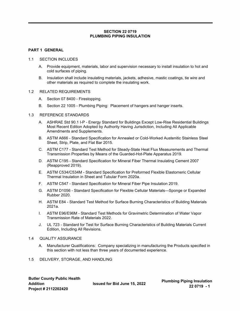
Butler County Public Health AdditionProject # 2112202420
Issued for Bid June 15, 2022 Plumbing Piping Insulation22 0719 - 1
SECTION 22 0719 PLUMBING PIPING INSULATION
PART 1 GENERAL
1.1 SECTION INCLUDES
A. Provide equipment, materials, labor and supervision necessary to install insulation to hot and cold surfaces of piping.
B. Insulation shall include insulating materials, jackets, adhesive, mastic coatings, tie wire and other materials as required to complete the insulating work.
1.2 RELATED REQUIREMENTS
A. Section 07 8400 - Firestopping.
B. Section 22 1005 - Plumbing Piping: Placement of hangers and hanger inserts.
1.3 REFERENCE STANDARDS
A. ASHRAE Std 90.1 I-P - Energy Standard for Buildings Except Low-Rise Residential Buildings Most Recent Edition Adopted by Authority Having Jurisdiction, Including All Applicable Amendments and Supplements.
B. ASTM A666 - Standard Specification for Annealed or Cold-Worked Austenitic Stainless Steel Sheet, Strip, Plate, and Flat Bar 2015.
C. ASTM C177 - Standard Test Method for Steady-State Heat Flux Measurements and Thermal Transmission Properties by Means of the Guarded-Hot-Plate Apparatus 2019.
D. ASTM C195 - Standard Specification for Mineral Fiber Thermal Insulating Cement 2007 (Reapproved 2019).
E. ASTM C534/C534M - Standard Specification for Preformed Flexible Elastomeric Cellular Thermal Insulation in Sheet and Tubular Form 2020a.
F. ASTM C547 - Standard Specification for Mineral Fiber Pipe Insulation 2019.
G. ASTM D1056 - Standard Specification for Flexible Cellular Materials—Sponge or Expanded Rubber 2020.
H. ASTM E84 - Standard Test Method for Surface Burning Characteristics of Building Materials 2021a.
I. ASTM E96/E96M - Standard Test Methods for Gravimetric Determination of Water Vapor Transmission Rate of Materials 2022.
J. UL 723 - Standard for Test for Surface Burning Characteristics of Building Materials Current Edition, Including All Revisions.
1.4 QUALITY ASSURANCE
A. Manufacturer Qualifications: Company specializing in manufacturing the Products specified in this section with not less than three years of documented experience.
1.5 DELIVERY, STORAGE, AND HANDLING
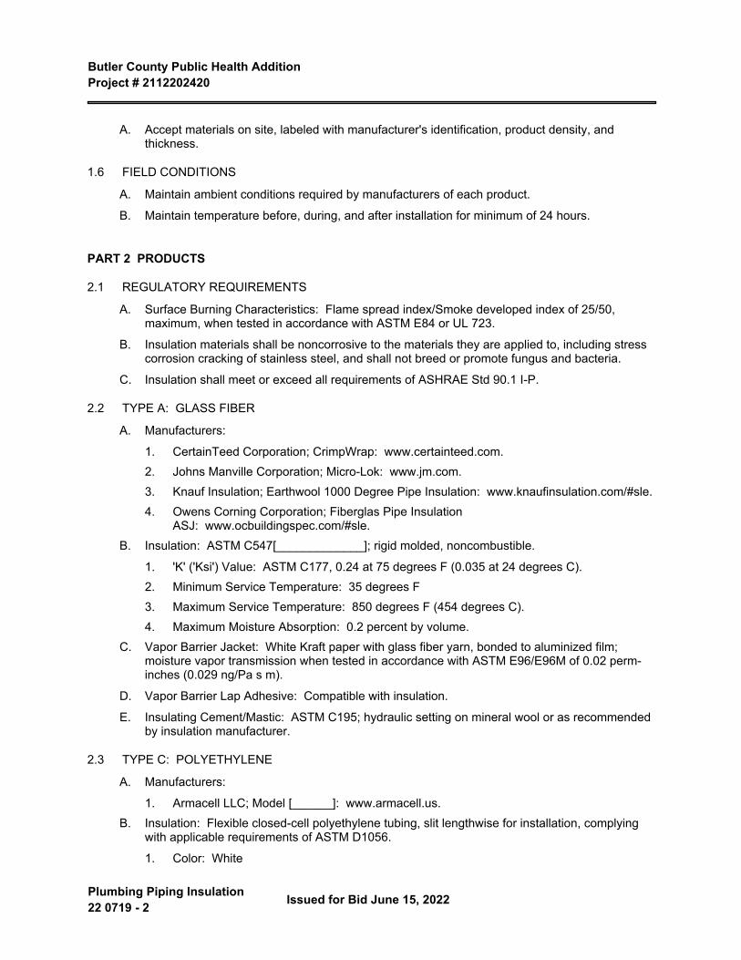
Butler County Public Health Addition Project # 2112202420
Plumbing Piping Insulation 22 0719 - 2 Issued for Bid June 15, 2022
A. Accept materials on site, labeled with manufacturer's identification, product density, and thickness.
1.6 FIELD CONDITIONS
A. Maintain ambient conditions required by manufacturers of each product.
B. Maintain temperature before, during, and after installation for minimum of 24 hours.
PART 2 PRODUCTS
2.1 REGULATORY REQUIREMENTS
A. Surface Burning Characteristics: Flame spread index/Smoke developed index of 25/50, maximum, when tested in accordance with ASTM E84 or UL 723.
B. Insulation materials shall be noncorrosive to the materials they are applied to, including stress corrosion cracking of stainless steel, and shall not breed or promote fungus and bacteria.
C. Insulation shall meet or exceed all requirements of ASHRAE Std 90.1 I-P.
2.2 TYPE A: GLASS FIBER
A. Manufacturers:
1. CertainTeed Corporation; CrimpWrap: www.certainteed.com.2. Johns Manville Corporation; Micro-Lok: www.jm.com.3. Knauf Insulation; Earthwool 1000 Degree Pipe Insulation: www.knaufinsulation.com/#sle.4. Owens Corning Corporation; Fiberglas Pipe Insulation
ASJ: www.ocbuildingspec.com/#sle.B. Insulation: ASTM C547[_____________]; rigid molded, noncombustible.
1. 'K' ('Ksi') Value: ASTM C177, 0.24 at 75 degrees F (0.035 at 24 degrees C).2. Minimum Service Temperature: 35 degrees F3. Maximum Service Temperature: 850 degrees F (454 degrees C).4. Maximum Moisture Absorption: 0.2 percent by volume.
C. Vapor Barrier Jacket: White Kraft paper with glass fiber yarn, bonded to aluminized film; moisture vapor transmission when tested in accordance with ASTM E96/E96M of 0.02 perm-inches (0.029 ng/Pa s m).
D. Vapor Barrier Lap Adhesive: Compatible with insulation.
E. Insulating Cement/Mastic: ASTM C195; hydraulic setting on mineral wool or as recommended by insulation manufacturer.
2.3 TYPE C: POLYETHYLENE
A. Manufacturers:
1. Armacell LLC; Model [______]: www.armacell.us.B. Insulation: Flexible closed-cell polyethylene tubing, slit lengthwise for installation, complying
with applicable requirements of ASTM D1056.
1. Color: White

Butler County Public Health Addition Project # 2112202420
Issued for Bid June 15, 2022 Plumbing Piping Insulation22 0719 - 3
2. 'K' ('Ksi') Value: ASTM C177; 0.25 at 75 degrees F (0.036 at 24 degrees C).3. Maximum Service Temperature: 200 degrees F (93 degrees C).4. Density: 2 lb/cu ft (32 kg/cu m).5. Maximum Moisture Absorption: 1.0 percent by volume.6. Moisture Vapor Permeability: 0.05 perm inch (0.073 ng/Pa s m), when tested in
accordance with ASTM E96/E96M.7. Connection: Contact adhesive.8. Butt joints sealed with 3M-471 tape.
2.4 TYPE B: FLEXIBLE ELASTOMERIC CELLULAR INSULATION
A. Manufacturer:
1. Aeroflex USA, Inc; [______]: www.aeroflexusa.com/#sle.2. Armacell LLC; AP Armaflex: www.armacell.us/#sle.3. K-Flex USA LLC; Insul-Tube: www.kflexusa.com/#sle.4. Substitutions: See Section 01 6000 - Product Requirements.
B. Insulation: Preformed flexible elastomeric cellular rubber insulation complying with ASTM C534/C534M Grade 1; use molded tubular material wherever possible.
1. Minimum Service Temperature: Minus 40 degrees F (Minus 40 degrees C).2. Maximum Service Temperature: 220 degrees F (104 degrees C).3. 'K' Value: ASTM C177; 0.28 at 75 degrees F.4. Connection: Waterproof vapor barrier adhesive.
C. Outdoor applications, and where otherwise noted, shall receive a weather-resistanat, protective, latex enamel finish, Armacell Armaflex WB.
D. Elastomeric Foam Adhesive: Air dried, contact adhesive, compatible with insulation.
2.5 TYPE M: PLENUM WRAP
A. Manufacturer:
1. 3M; Fire Barrier Plenum Wrap 5A+2. Substitutions: See Section 01 6000 - Product Requirements.
B. Insulation: Non asbestos containing, inorganic fiber blanket encapsulated with a scrim-reinforced foil, tested to ASTM E84, NFPA 262 (UL 910) and UL 1887.
1. Density: 6 pcf2. Joining: 3M FSK Facing Tape 3320 or as recommended by manufacturer.3. Maximum flame spread over PVC: 2.6 ft.4. Maximum flame spread and smoke developed rating over PVC: 5.5. Install per manufacturer's written instructions.
2.6 JACKETS
A. PVC Plastic.
1. Manufacturers:
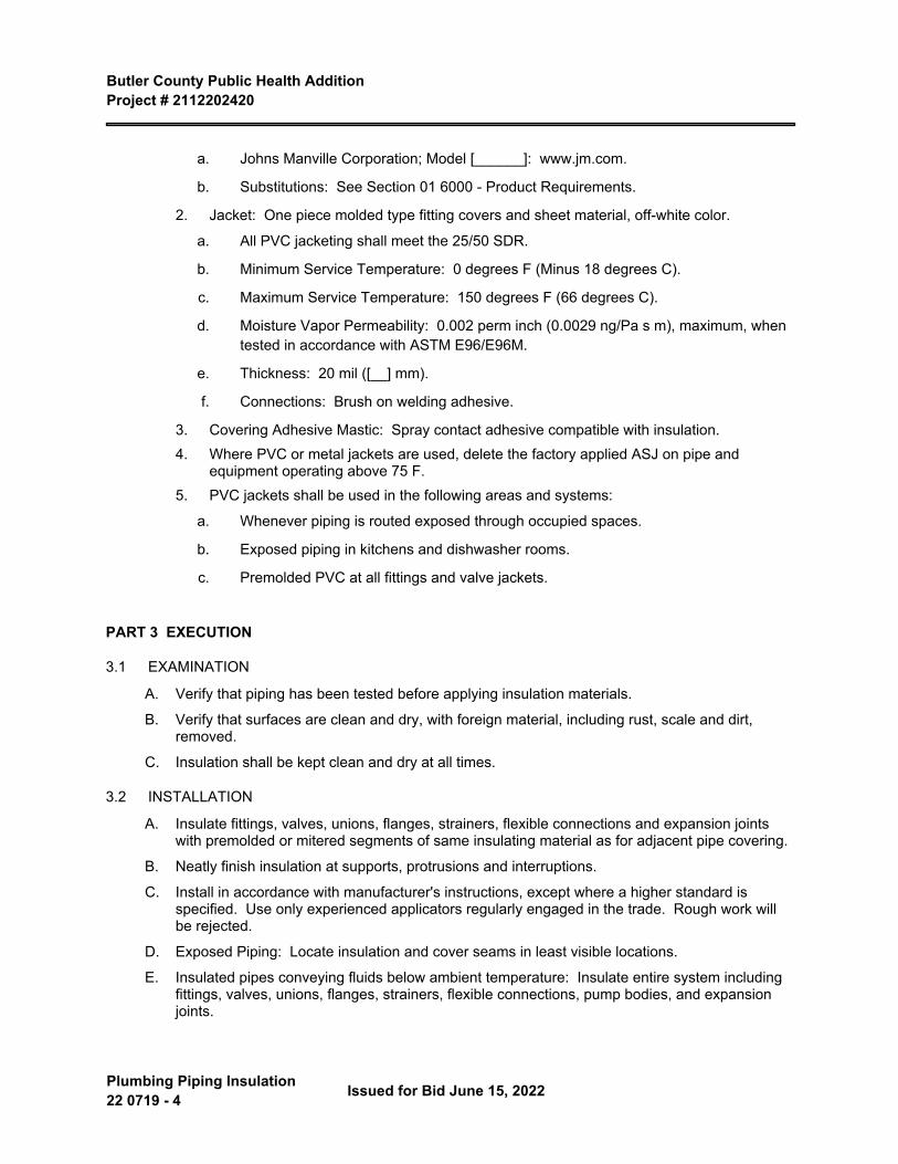
Butler County Public Health Addition Project # 2112202420
Plumbing Piping Insulation 22 0719 - 4 Issued for Bid June 15, 2022
a. Johns Manville Corporation; Model [______]: www.jm.com.
b. Substitutions: See Section 01 6000 - Product Requirements.
2. Jacket: One piece molded type fitting covers and sheet material, off-white color.
a. All PVC jacketing shall meet the 25/50 SDR.
b. Minimum Service Temperature: 0 degrees F (Minus 18 degrees C).
c. Maximum Service Temperature: 150 degrees F (66 degrees C).
d. Moisture Vapor Permeability: 0.002 perm inch (0.0029 ng/Pa s m), maximum, when tested in accordance with ASTM E96/E96M.
e. Thickness: 20 mil ([__] mm).
f. Connections: Brush on welding adhesive.
3. Covering Adhesive Mastic: Spray contact adhesive compatible with insulation.4. Where PVC or metal jackets are used, delete the factory applied ASJ on pipe and
equipment operating above 75 F.5. PVC jackets shall be used in the following areas and systems:
a. Whenever piping is routed exposed through occupied spaces.
b. Exposed piping in kitchens and dishwasher rooms.
c. Premolded PVC at all fittings and valve jackets.
PART 3 EXECUTION
3.1 EXAMINATION
A. Verify that piping has been tested before applying insulation materials.
B. Verify that surfaces are clean and dry, with foreign material, including rust, scale and dirt, removed.
C. Insulation shall be kept clean and dry at all times.
3.2 INSTALLATION
A. Insulate fittings, valves, unions, flanges, strainers, flexible connections and expansion joints with premolded or mitered segments of same insulating material as for adjacent pipe covering.
B. Neatly finish insulation at supports, protrusions and interruptions.
C. Install in accordance with manufacturer's instructions, except where a higher standard is specified. Use only experienced applicators regularly engaged in the trade. Rough work will be rejected.
D. Exposed Piping: Locate insulation and cover seams in least visible locations.
E. Insulated pipes conveying fluids below ambient temperature: Insulate entire system including fittings, valves, unions, flanges, strainers, flexible connections, pump bodies, and expansion joints.
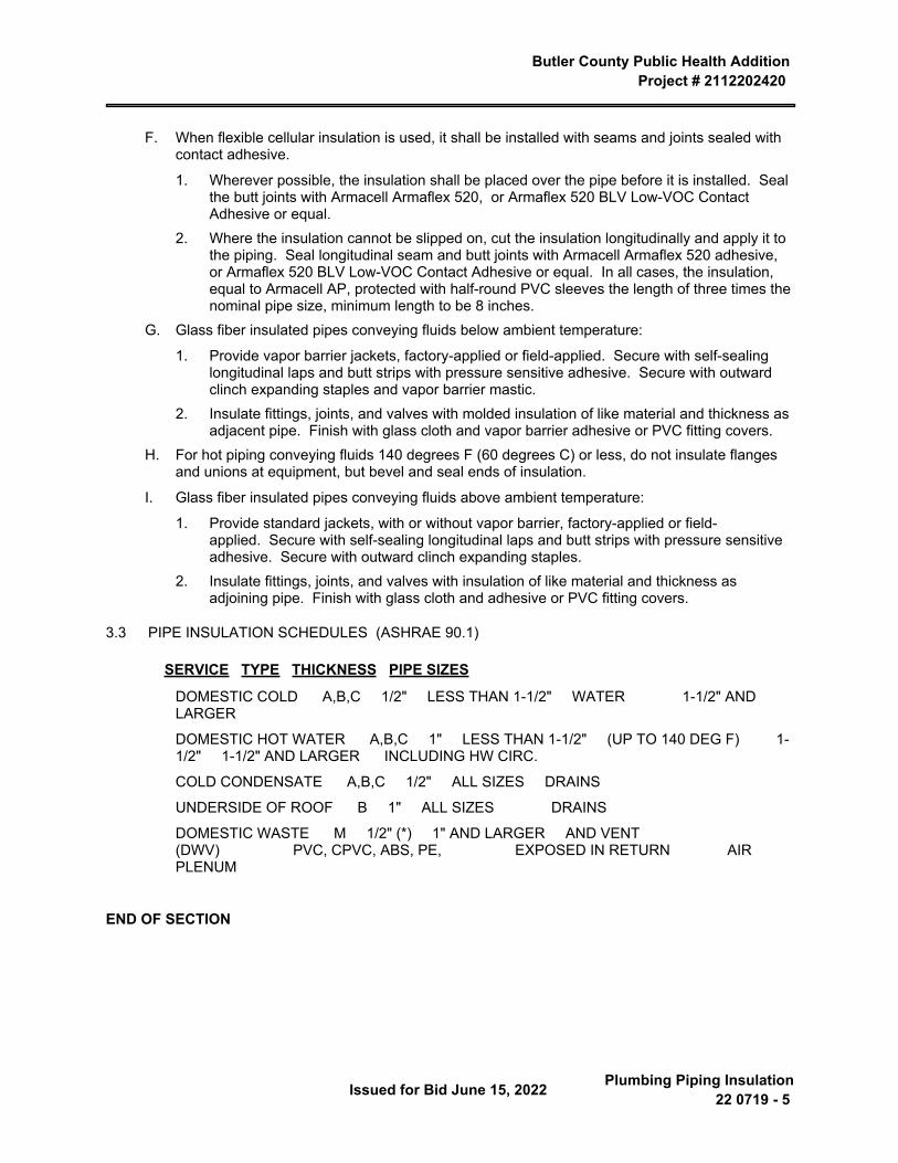
Butler County Public Health Addition Project # 2112202420
Issued for Bid June 15, 2022 Plumbing Piping Insulation22 0719 - 5
F. When flexible cellular insulation is used, it shall be installed with seams and joints sealed with contact adhesive.
1. Wherever possible, the insulation shall be placed over the pipe before it is installed. Seal the butt joints with Armacell Armaflex 520, or Armaflex 520 BLV Low-VOC Contact Adhesive or equal.
2. Where the insulation cannot be slipped on, cut the insulation longitudinally and apply it to the piping. Seal longitudinal seam and butt joints with Armacell Armaflex 520 adhesive, or Armaflex 520 BLV Low-VOC Contact Adhesive or equal. In all cases, the insulation, equal to Armacell AP, protected with half-round PVC sleeves the length of three times the nominal pipe size, minimum length to be 8 inches.
G. Glass fiber insulated pipes conveying fluids below ambient temperature:
1. Provide vapor barrier jackets, factory-applied or field-applied. Secure with self-sealing longitudinal laps and butt strips with pressure sensitive adhesive. Secure with outward clinch expanding staples and vapor barrier mastic.
2. Insulate fittings, joints, and valves with molded insulation of like material and thickness as adjacent pipe. Finish with glass cloth and vapor barrier adhesive or PVC fitting covers.
H. For hot piping conveying fluids 140 degrees F (60 degrees C) or less, do not insulate flanges and unions at equipment, but bevel and seal ends of insulation.
I. Glass fiber insulated pipes conveying fluids above ambient temperature:
1. Provide standard jackets, with or without vapor barrier, factory-applied or field-applied. Secure with self-sealing longitudinal laps and butt strips with pressure sensitive adhesive. Secure with outward clinch expanding staples.
2. Insulate fittings, joints, and valves with insulation of like material and thickness as adjoining pipe. Finish with glass cloth and adhesive or PVC fitting covers.
3.3 PIPE INSULATION SCHEDULES (ASHRAE 90.1)
SERVICE TYPE THICKNESS PIPE SIZES
DOMESTIC COLD A,B,C 1/2" LESS THAN 1-1/2" WATER 1-1/2" AND LARGER
DOMESTIC HOT WATER A,B,C 1" LESS THAN 1-1/2" (UP TO 140 DEG F) 1-1/2" 1-1/2" AND LARGER INCLUDING HW CIRC.
COLD CONDENSATE A,B,C 1/2" ALL SIZES DRAINS
UNDERSIDE OF ROOF B 1" ALL SIZES DRAINS
DOMESTIC WASTE M 1/2" (*) 1" AND LARGER AND VENT (DWV) PVC, CPVC, ABS, PE, EXPOSED IN RETURN AIR PLENUM
END OF SECTION

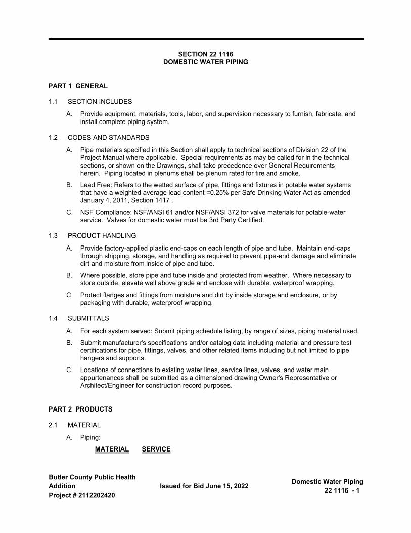
Butler County Public Health AdditionProject # 2112202420
Issued for Bid June 15, 2022 Domestic Water Piping22 1116 - 1
SECTION 22 1116 DOMESTIC WATER PIPING
PART 1 GENERAL
1.1 SECTION INCLUDES
A. Provide equipment, materials, tools, labor, and supervision necessary to furnish, fabricate, and install complete piping system.
1.2 CODES AND STANDARDS
A. Pipe materials specified in this Section shall apply to technical sections of Division 22 of the Project Manual where applicable. Special requirements as may be called for in the technical sections, or shown on the Drawings, shall take precedence over General Requirements herein. Piping located in plenums shall be plenum rated for fire and smoke.
B. Lead Free: Refers to the wetted surface of pipe, fittings and fixtures in potable water systems that have a weighted average lead content =0.25% per Safe Drinking Water Act as amended January 4, 2011, Section 1417 .
C. NSF Compliance: NSF/ANSI 61 and/or NSF/ANSI 372 for valve materials for potable-water service. Valves for domestic water must be 3rd Party Certified.
1.3 PRODUCT HANDLING
A. Provide factory-applied plastic end-caps on each length of pipe and tube. Maintain end-caps through shipping, storage, and handling as required to prevent pipe-end damage and eliminate dirt and moisture from inside of pipe and tube.
B. Where possible, store pipe and tube inside and protected from weather. Where necessary to store outside, elevate well above grade and enclose with durable, waterproof wrapping.
C. Protect flanges and fittings from moisture and dirt by inside storage and enclosure, or by packaging with durable, waterproof wrapping.
1.4 SUBMITTALS
A. For each system served: Submit piping schedule listing, by range of sizes, piping material used.
B. Submit manufacturer's specifications and/or catalog data including material and pressure test certifications for pipe, fittings, valves, and other related items including but not limited to pipe hangers and supports.
C. Locations of connections to existing water lines, service lines, valves, and water main appurtenances shall be submitted as a dimensioned drawing Owner's Representative or Architect/Engineer for construction record purposes.
PART 2 PRODUCTS
2.1 MATERIAL
A. Piping:
MATERIAL SERVICE

Butler County Public Health Addition Project # 2112202420
Domestic Water Piping 22 1116 - 2 Issued for Bid June 15, 2022
Ductile iron water pipe, standard Underground water service main 3" dia. mechanical joint. ASTM A 536. ANSI A21.5 and larger. AWWA C151
Copper water tube, hard temper ASTM B88:
Type K Domestic water piping lines under building, concealed in solid concrete or masonry walls or construction; underground water service up to 3" dia.Type L Aboveground domestic water piping lines.
PVC pipe, Schedule 40, ASTM D1785 Aboveground and belowground domestic water piping lines.
Brass pipe, Schedule 40, chromium Exposed piping connections for plumbing plated, ASTM B43 fixtures, showers and chrome plated tanks.
B. Fittings:
1. Cast iron water pipe - Class 250, ANSI A21.20, AWWA C110, standard mechanical joint fitting with lugs for connecting to pipe.
2. Threaded pipe - ASME B16.3 malleable iron fittings, 125-pound, standard flat band water pattern.
3. Copper water tube, cast bronze or wrought copper, solder joint type. ANSI B16.18 and B16.22.
4. PVC pipe - Schedule 40 fittings, socket-type, ASTM D2466.5. Brass pipe - cast bronze screwed, 125 pound, flat band water pattern, chromium plated, for
chromium-plated pipe.
2.2 JOINTS
A. Threaded pipe - make joints using approved pipe joint compound, applied to male threads only. Cut pipe square, cut threads clean, remove burrs, and ream ends to full size of bore. Threads shall not be exposed on chromium-plated pipe.
B. Welded pipe - welding shall conform to welding sections of ASME B31.1 "Code for Power Piping". Pipe up to 2" diameter shall be threaded and coupled and Pipe 2-1/2" diameter or larger shall be welded.
C. Copper water and drainage tube - use 95-5 tin antimony or silver solder, cut pipe square, clean and polish tube ends and inner surface of fittings, apply flux and solder joint as recommended by manufacturer of solder type fittings. Use same methods for copper refrigerant pipe, except use silver solder with 15% silver content, equivalent to Sil-Flos 15.
D. Solid wall schedule 40 PVC DWV - solvent cemented joints per ASTM D2466.
E. Threadless brass pipe - use brazing alloy which will flow freely at 1300 degree F. Use flux and brazing method as recommended by manufacturer of brazing alloy.
F. When soldering use paste fluxes that are approved by the manufacturer for use with Lead Free Alloys.
2.3 GENERAL VALVE APPLICATIONS
A. Drawings indicate valve types to be used. If valve applications are not indicated, use the following:
1. Shutoff Service: Ball, Butterfly, or Gate valves.
a. Piping NPS 2 (DN 50) and smaller: Furnish bronze ball or gate valves.
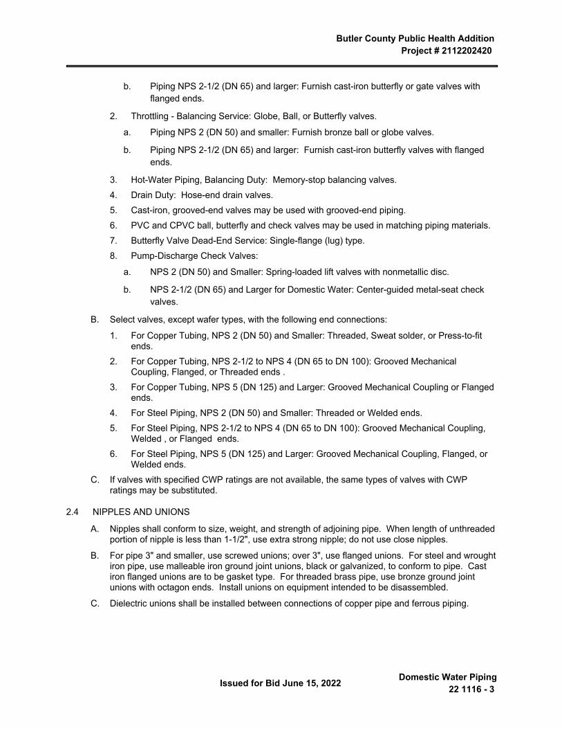
Butler County Public Health Addition Project # 2112202420
Issued for Bid June 15, 2022 Domestic Water Piping22 1116 - 3
b. Piping NPS 2-1/2 (DN 65) and larger: Furnish cast-iron butterfly or gate valves with flanged ends.
2. Throttling - Balancing Service: Globe, Ball, or Butterfly valves.
a. Piping NPS 2 (DN 50) and smaller: Furnish bronze ball or globe valves.
b. Piping NPS 2-1/2 (DN 65) and larger: Furnish cast-iron butterfly valves with flanged ends.
3. Hot-Water Piping, Balancing Duty: Memory-stop balancing valves.4. Drain Duty: Hose-end drain valves.5. Cast-iron, grooved-end valves may be used with grooved-end piping.6. PVC and CPVC ball, butterfly and check valves may be used in matching piping materials.7. Butterfly Valve Dead-End Service: Single-flange (lug) type.8. Pump-Discharge Check Valves:
a. NPS 2 (DN 50) and Smaller: Spring-loaded lift valves with nonmetallic disc.
b. NPS 2-1/2 (DN 65) and Larger for Domestic Water: Center-guided metal-seat check valves.
B. Select valves, except wafer types, with the following end connections:
1. For Copper Tubing, NPS 2 (DN 50) and Smaller: Threaded, Sweat solder, or Press-to-fit ends.
2. For Copper Tubing, NPS 2-1/2 to NPS 4 (DN 65 to DN 100): Grooved Mechanical Coupling, Flanged, or Threaded ends .
3. For Copper Tubing, NPS 5 (DN 125) and Larger: Grooved Mechanical Coupling or Flanged ends.
4. For Steel Piping, NPS 2 (DN 50) and Smaller: Threaded or Welded ends.5. For Steel Piping, NPS 2-1/2 to NPS 4 (DN 65 to DN 100): Grooved Mechanical Coupling,
Welded , or Flanged ends.6. For Steel Piping, NPS 5 (DN 125) and Larger: Grooved Mechanical Coupling, Flanged, or
Welded ends.C. If valves with specified CWP ratings are not available, the same types of valves with CWP
ratings may be substituted.
2.4 NIPPLES AND UNIONS
A. Nipples shall conform to size, weight, and strength of adjoining pipe. When length of unthreaded portion of nipple is less than 1-1/2", use extra strong nipple; do not use close nipples.
B. For pipe 3" and smaller, use screwed unions; over 3", use flanged unions. For steel and wrought iron pipe, use malleable iron ground joint unions, black or galvanized, to conform to pipe. Cast iron flanged unions are to be gasket type. For threaded brass pipe, use bronze ground joint unions with octagon ends. Install unions on equipment intended to be disassembled.
C. Dielectric unions shall be installed between connections of copper pipe and ferrous piping.
Butler County Public Health Addition Project # 2112202420
Domestic Water Piping 22 1116 - 4 Issued for Bid June 15, 2022
2.5 SLEEVES
A. Floor sleeves shall be provided by the contractor. Coordinate with existing structure and notify engineer if structure interferes with design.
B. Sleeves passing through non-load bearing walls and partitions shall be galvanized sheet steel with lock seam joints of minimum gauges as follows: For pipes 2-1/2" in size and smaller - 24-gauge; 3 in. to 6 in. - 22-gauge; over 6 in. - 20-gauge.
C. Sleeves passing through load bearing walls, concrete beams, fireproof walls, foundations, footings, and waterproof floors shall be Schedule 40 galvanized steel pipe or cast iron pipe.
D. Sleeves for insulated piping shall be of sufficient internal diameter to take pipe and insulation and to allow for free movement of pipe. Waterproof sleeves shall be of sufficient internal diameter to take pipe and waterproofing material.
E. In finished areas where pipes are exposed, sleeves shall be terminated flush with wall, partitions and ceilings, and shall extend 1/2 in. above finished floors. Extend sleeves 1 in. above finished floors in areas likely to entrap water and fill space between sleeves and pipe with graphite packing and caulking compound.
F. Sleeves passing through membrane waterproofing or roofing shall be flashed and sealed.
2.6 PIPE ESCUTCHEONS
A. Provide pipe escutcheons with inside diameter closely fitting pipe outside diameter, or outside of pipe insulation where pipe is insulated. Select outside diameter of escutcheon to completely cover pipe penetration hole in floors, walls, or ceilings; and pipe sleeve extensions, if any. Furnish pipe escutcheons with chrome finish for occupied areas, prime paint finish for unoccupied areas.
B. Pipe Escutcheons for Moist Areas: For waterproof floors, and areas where water and condensation can be expected to accumulate, provide cast brass or sheet brass escutcheons, solid or split hinged.
C. Pipe Escutcheons for Dry Areas: Provide sheet steel escutcheons, solid or split hinged.
D. Manufacturer: Chicago Specialty; Producers Specialty; or Sanitary-Dash.
2.7 GUARDS
A. Where exposed insulated piping extends through floor, provide sheet metal guard around insulation to extend up from floor 60 inches. Guard to be galvanized sheet steel not less than 26-gauge.
2.8 FIRE SAFING
A. Metal piping and sleeves passing through floors, roof, partitions and fire walls, shall be provided with firestop by packing space between pipe and sleeve with UL listed non-sag and self-leveling fire safing insulation per manufacturer's instructions.
B. Plastic piping passing through fire rated floors and fire rated walls shall be provided with firestop by providing intumescent wrap strip around the pipe, enclosed in steel collar attached to structure.
C. Cracks, Voids, or Holes Up to 4" Diameter: Use non-sag or self-leveling putty or caulking, one-piece intumescent elastomer, non-corrosive to metal, compatible with synthetic cable jackets, and capable of expanding 10 times when exposed to flame or heat, UL listed.
Butler County Public Health Addition Project # 2112202420
Issued for Bid June 15, 2022 Domestic Water Piping22 1116 - 5
D. Openings 4" or Greater: Use sealing system capable of passing 3-hour fire test in accordance with ASTM E814, consisting of wall wrap or liner, partitions, and end caps capable of expanding when exposed to temperatures of 250 to 350 degree F (121 to 177 degree C), UL listed.
E. Seal all holes or voids made by penetrations to ensure an effective barrier against smoke, fire, toxic and combustible gases.
F. Unless protected, from possible loading or traffic, install firestopping materials in floors having void openings or four (4) inches or more to support the same floor load requirements.
G. Manufacturer: Subject to compliance with requirements, provide non-sag and self-leveling fire barrier caulk, wrap/strip, moldable putty and sheet forms of one of the following:
1. 3M Brand.2. Flame Stop.3. Dow Corning.4. Metacaulk.
H. Horizontal penetrations through fire rated walls where plenum rated cables or tubing bundles are being installed shall be made with EZ-Path Fire-rated Pathway by Specified Technologies, Inc.
2.9 MECHANICAL SLEEVE SEALS
A. Modular mechanical type, consisting of interlocking synthetic rubber links shaped to continuously fill annular space between pipe and sleeve, connected with bolts and pressure plates which cause rubber sealing elements to expand when tightened, providing watertight seal and electrical insulation.
B. Manufacturer: Thunderline.
2.10 WATER METERS
A. Consult with Utility as to extent of work, costs, fees, and permits involved. Pay such costs and fees; obtain permits.
B. The meter construction shall include cast bronze meter housing, stainless steel trim and disc spindle.
PART 3 EXECUTION
3.1 INSTALLATION
A. Install pipe for plumbing and mechanical systems as shown on the Drawings, as called for in other Sections, and as specified herein
B. Arrange and install piping approximately as indicated, straight, plumb, and as direct as possible, form right angles on parallel lines with building walls. Keep pipes close to walls, partitions, and ceilings, offsetting only where necessary to follow walls and avoid interference with other mechanical items. Locate groups of pipes parallel to each other; space at a distance to permit applying full insulation and to permit access for servicing valves. Piping to be run in concealed locations unless indicated exposed, or in equipment rooms.
C. Install horizontal piping as high as possible without sags or humps so that proper grades can be maintained for drainage. Branch piping shall come off the tops of mains unless shown otherwise.
Butler County Public Health Addition Project # 2112202420
Domestic Water Piping 22 1116 - 6 Issued for Bid June 15, 2022
D. Locate valves within reachable distance from equipment being served for easy access and operation. Do not locate valves with stems below horizontal.
E. Check piping for interference with other trades; avoid placing water pipes over electrical equipment.
F. Verify final equipment locations before roughing in.
G. Where rough-ins are required for equipment furnished by others, verify exact rough-in dimensions with Owner or equipment supplier before roughing-in.
H. Roll cut or groove piping ends as required based on piping material, wall thickness, size, pressure and joining methods. Refer to manufacturer's installation instructions. All grooved products covered under this section shall be furnished by one manufacturer.
I. Press fit piping connections shall be made in accordance with manufacturer's installation instructions, using the manufacturer's approved tools and methods. Installation must meet or exceed IAPMO PS 117 functional performance criteria.
J. Install shutoff valve close to water main on each branch and riser serving plumbing fixtures or equipment, on each water supply to equipment, and on each water supply to plumbing fixtures that do not have supply stops. Use ball or gate valves for piping NPS 2 (DN 50) and smaller. Use butterfly or gate valves for piping NPS 2-1/2 (DN 65) and larger.
K. Install drain valves for equipment at base of each water riser, at low points in horizontal piping, and where required to drain water piping.
1. Install hose-end drain valves at low points in water mains, risers, and branches.2. Install stop-and-waste drain valves where indicated.
L. Install balancing valve in each hot-water circulation return branch and discharge side of each pump and circulator. Set balancing valves partly open to restrict but not stop flow. Use ball valves for piping NPS 2 (DN 50) and smaller and butterfly valves for piping NPS 2-1/2 (DN 65) and larger. Balancing valves are specified in Division 22 Section "Domestic Water Piping Specialties."
M. Install calibrated balancing valves in each hot-water circulation return branch and discharge side of each pump and circulator. Set calibrated balancing valves partly open to restrict but not stop flow. Calibrated balancing valves are specified in Division 22 Section "Domestic Water Piping Specialties."
3.2 WATER METER INSTALLATION
A. Rough-in domestic water piping for water meter installation and install water meter(s) according to Utility company's requirements.
B. Water meters will be provided and installed by Utility company. Contractor shall pay required costs and fees.
C. Water Meter Type:
1. Install displacement-type water meters with shutoff valve on water-meter inlet. Install valve on water-meter outlet and valved bypass around meter unless prohibited by Authorities Having Jurisdiction.
3.3 SLEEVES
A. Install sleeves for piping passing through floors, roof, walls and foundations.
B. Install fire-proofing per manufacturer's written instructions.
Butler County Public Health Addition Project # 2112202420
Issued for Bid June 15, 2022 Domestic Water Piping22 1116 - 7
3.4 ESCUTCHEONS
A. Install escutcheons for pipes entering finished spaces.
3.5 MECHANICAL SLEEVE SEAL INSTALLATION
A. Install mechanical sleeve seals at all pipe penetrations through foundations below grade.
B. Loosely assemble rubber links around pipe and bolts and pressure plates located under each bolt head and nut. Push into sleeve and center. Tighten bolts until links have expanded to form watertight seal.
3.6 PIPE PENETRATIONS
A. Penetrations shall be free of debris and dirt. Dam the penetration (when required) with an acceptable material. Apply firestop material to the penetration per manufacturer's installation instructions. Use a caulking gun, putty knife or other normal trade tools. Remove damming materials where necessary after cure. Clean up with Xylene.
3.7 FIRE SAFING
A. Install fire safing at all penetrations through walls, floors, etc. per manufacturer's installation instructions as required to meet UL listing.
3.8 FIELD QUALITY CONTROL
A. Inspect domestic water piping as follows:
1. Do not enclose, cover, or put piping into operation until it has been inspected and approved by authorities having jurisdiction.
2. During installation, notify authorities having jurisdiction at least 24 hours before inspection must be made. Perform tests specified below in presence of authorities having jurisdiction:
a. Roughing-in Inspection: Arrange for inspection of piping before concealing or closing-in after roughing-in and before setting fixtures.
b. Final Inspection: Arrange final inspection for authorities having jurisdiction to observe tests specified below and to ensure compliance with requirements.
3. Re-inspection: If authorities having jurisdiction find that piping will not pass test or inspection, make required corrections and arrange for re-inspection.
4. Reports: Prepare inspection reports and have them signed by authorities having jurisdiction.
B. Test domestic water piping as follows:
1. Fill domestic water piping. Check components to determine that they are not air bound and that piping is full of water.
2. Test for leaks and defects in new piping and parts of existing piping that have been altered, extended, or repaired. If testing is performed in segments, submit separate report for each test, complete with diagram of portion of piping tested.
3. Leave new, altered, extended, or replaced domestic water piping uncovered and unconcealed until it has been tested and approved. Expose work that was covered or concealed before it was tested.
4. Cap and subject piping to static water pressure of 50 psig (345 kPa) above operating pressure, without exceeding pressure rating of piping system materials. Isolate test
Butler County Public Health Addition Project # 2112202420
Domestic Water Piping 22 1116 - 8 Issued for Bid June 15, 2022
source and allow to stand for four hours. Leaks and loss in test pressure constitute defects that must be repaired.
5. Repair leaks and defects with new materials and retest piping or portion thereof until satisfactory results are obtained.
6. Prepare reports for tests and required corrective action.
3.9 ADJUSTING
A. Perform the following adjustments before operation:
1. Close drain valves, hydrants, and hose bibbs.2. Open shutoff valves to fully open position.3. Open throttling valves to proper setting.4. Adjust balancing valves in hot-water-circulation return piping to provide adequate flow.
a. Manually adjust ball-type balancing valves in hot-water-circulation return piping to provide flow of hot water in each branch.
b. Adjust calibrated balancing valves to flows indicated.
5. Remove plugs used during testing of piping and plugs used for temporary sealing of piping during installation.
6. Remove and clean strainer screens. Close drain valves and replace drain plugs.7. Remove filter cartridges from housings and verify that cartridges are as specified for
application where used and are clean and ready for use.8. Check plumbing specialties and verify proper settings, adjustments, and operation.
3.10 CLEANING
A. Domestic water piping shall be cleaned and disinfected prior to substantial completion. Immediately prior to occupancy, the system(s) shall be flushed and a water sample submitted to the local Water Works for testing.
B. Clean and disinfect potable domestic water piping as follows:
1. Purge new piping and parts of existing domestic water piping that have been altered, extended, or repaired before using.
2. Use purging and disinfecting procedures prescribed by authorities having jurisdiction or, if methods are not prescribed, procedures described in either AWWA C651 or AWWA C652 or as described below:
a. Flush piping system with clean, potable water until dirty water does not appear at outlets.
b. Fill and isolate system according to either of the following:
1) Fill system or part thereof with water/chlorine solution with at least 50 ppm (50 mg/L) of chlorine. Isolate with valves and allow to stand for 24 hours.
2) Fill system or part thereof with water/chlorine solution with at least 200 ppm (200 mg/L) of chlorine. Isolate and allow to stand for three hours.(a) Flush system with clean, potable water until no chlorine is in water coming
from system after the standing time.
Butler County Public Health Addition Project # 2112202420
Issued for Bid June 15, 2022 Domestic Water Piping22 1116 - 9
(b) Submit water samples in sterile bottles to authorities having jurisdiction. Repeat procedures if biological examination shows contamination.
C. Clean interior of domestic water piping system. Remove dirt and debris as work progresses.
D. Prepare and submit reports of purging and disinfecting activities.
END OF SECTION 22 1116

Butler County Public Health AdditionProject # 2112202420
Issued for Bid June 15, 2022 Crosslinked Polyethylene
Domestic Water Piping22 1117 - 1
SECTION 22 1117 CROSSLINKED POLYETHYLENE DOMESTIC WATER PIPING
PART 1 GENERAL
1.1 SECTION INCLUDES
A. Potable hot and cold water branch piping, using crosslinked polyethylene (PEX) tubing and cold expansion fittings with reinforcing rings.
1.2 REFERENCE STANDARDS
A. ASTM International
1. ASTM E84 Standard Test Method for Surface Burning Characteristics of Building Materials.
2. ASTM E119 Standard Test Methods for Fire Tests of Building Construction and Materials.3. ASTM E814 Standard Test Method for Fire Tests of Through-Penetration Fire Stops4. ASTM F876 Standard Specification for Cross-linked Polyethylene (PEX) Tubing5. ASTM F877 Standard Specification for Cross-linked Polyethylene (PEX) Plastic Hot- and
Cold-Water Distribution Systems6. ASTM F1960 Standard specification for Cold Expansion Fittings with PEX reinforcing
Rings for Use with Cross-linked Polyethylene (PEX) TubingB. American National Standards Institute (ANSI)/National Sanitation Foundation (NSF)
1. ANSI/NSF Standard 14 Plastics Piping System Components and Related Materials2. ANSI/NSF Standard 61 Drinking Water System Components – Health Effects
C. American National Standards Institute (ANSI)/Underwriters Laboratories, Inc. (UL)
1. ANSI/UL 263 Standard for Safety for Fire Tests of Building Construction and MaterialsD. International Code Council (ICC) Evaluation Service Report No. ESR 1099
E. The International Association of Plumbing and Mechanical Officials (IAMPO) Files 3558, 3946, and 3960.
F. Plastics Pipe Institute (PPI) Technical Report TR-4/06
G. Uponor, Inc., Professional Plumbing Installation Guide, 2010
1.3 QUALITY ASSURANCE
A. Installer Qualifications: Use an installer with demonstrated experience on projects of similar size and complexity and possessing documentation proving successful completion of PEX plumbing installation training by the PEX tubing manufacturer.
B. Regulatory Requirements and Approvals: Provide domestic potable system that complies with requirements of the following:
1. International Code Council (ICC) Evaluation Service Report No. ESR 10992. IAMPO - Files 3558, 3946, and 3960.
C. Certifications: Provide letters of certification as follows:
Butler County Public Health Addition Project # 2112202420
Crosslinked Polyethylene Domestic Water Piping 22 1117 - 2
Issued for Bid June 15, 2022
1. Installer is trained by the PEX tubing manufacturer to install the PEX potable water distribution system.
2. Installer will use skilled workers holding a trade qualification license or equivalent, or apprentices under the supervision of a licensed trades professional.
1.4 SUBMITTALS
A. Submit shop drawings and catalog data for plumbing equipment as called for in Division 01 - General Requirements.
B. Product Data: Submit manufacturer’s product submittal data and installation instructions.
C. Quality Assurance/Control Submittals: Submit the following:
1. Test Reports: Upon request, submit test reports from recognized testing laboratories.2. Certificates: Submit the following:
a. Manufacturer’s certificate that products comply with specified requirements.
b. Certificate indicating that the installer is authorized to install the manufacturer’s products.
D. Closeout Submittals: Submit the following:
1. Warranty documents specified herein.2. Operation and Maintenance data.
1.5 SYSTEM DESCRIPTION
A. Design Requirements
1. Standard grade hydrostatic pressure ratings from Plastics Pipe Institute (PPI) in accordance with TR-3 as listed in TR-4. The following three standard-grade hydrostatic ratings are required:
a. 200°F (93°C) at 80 psi (551 kPa)
b. 180°F (82°C) at 100 psi (689 kPa)
c. 73.4°F (23°C) at 160 psi (1,102 kPa)
2. Certification of flame spread/smoke development rating of 25/50 in accordance with ASTM E84 provided the installation meets one of the following requirements:
a. Tubing spacing is a minimum of 18 inches apart for the following sizes:
1) 3/8 inch (9.53mm)2) 1/2 inch (12.7mm)3) 5/8 inch (15.88mm)4) 3/4 inch (19.05mm)
b. Each tube is wrapped with ½” fiberglass insulation with a flame spread of not more than 20 and a smoke-developed rating of not more than 30 and a nominal density of 4.0 to 4.5 pcf.
1) Tubing can run with three tubes separated by zero inches and then 18 inches between the next group of three tubes.
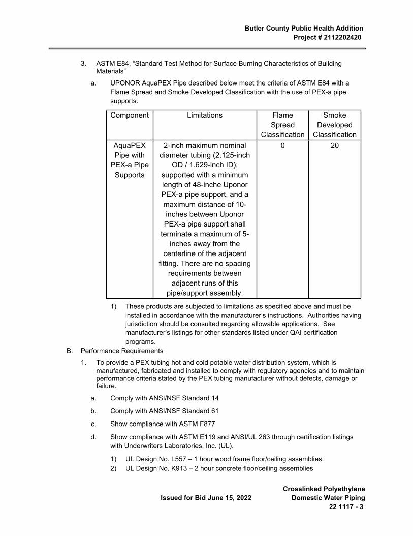
Butler County Public Health Addition Project # 2112202420
Issued for Bid June 15, 2022 Crosslinked Polyethylene
Domestic Water Piping22 1117 - 3
3. ASTM E84, “Standard Test Method for Surface Burning Characteristics of Building Materials”
a. UPONOR AquaPEX Pipe described below meet the criteria of ASTM E84 with a Flame Spread and Smoke Developed Classification with the use of PEX-a pipe supports.
Component Limitations Flame Spread
Classification
Smoke Developed
ClassificationAquaPEX Pipe with
PEX-a PipeSupports
2-inch maximum nominal diameter tubing (2.125-inch
OD / 1.629-inch ID); supported with a minimum length of 48-inche Uponor PEX-a pipe support, and a maximum distance of 10-inches between Uponor PEX-a pipe support shall
terminate a maximum of 5-inches away from the
centerline of the adjacent fitting. There are no spacing
requirements between adjacent runs of this
pipe/support assembly.
0 20
1) These products are subjected to limitations as specified above and must be installed in accordance with the manufacturer’s instructions. Authorities having jurisdiction should be consulted regarding allowable applications. See manufacturer’s listings for other standards listed under QAI certification programs.
B. Performance Requirements
1. To provide a PEX tubing hot and cold potable water distribution system, which is manufactured, fabricated and installed to comply with regulatory agencies and to maintain performance criteria stated by the PEX tubing manufacturer without defects, damage or failure.
a. Comply with ANSI/NSF Standard 14
b. Comply with ANSI/NSF Standard 61
c. Show compliance with ASTM F877
d. Show compliance with ASTM E119 and ANSI/UL 263 through certification listings with Underwriters Laboratories, Inc. (UL).
1) UL Design No. L557 – 1 hour wood frame floor/ceiling assemblies.2) UL Design No. K913 – 2 hour concrete floor/ceiling assemblies
Butler County Public Health Addition Project # 2112202420
Crosslinked Polyethylene Domestic Water Piping 22 1117 - 4
Issued for Bid June 15, 2022
3) UL Design No. U372 – 1 hour wood stud/gypsum wallboard wall assemblies.4) UL Design No. V444 – 1 hour steel stud/gypsum wallboard wall assemblies.
1.6 DELIVERY, STORAGE AND HANDLING
A. Comply with manufacturer’s ordering instructions and lead-time requirements to avoid construction delays.
B. Deliver materials in manufacturer’s original, unopened, undamaged containers with identification labels intact.
C. Store materials protected from exposure to harmful environmental conditions and at temperature and humidity conditions recommended by the manufacturer.
1. Store PEX tubing in cartons or under cover to avoid dirt or foreign material from being introduced into the tubing.
2. Do not expose PEX tubing to direct sunlight for more than 30 days. If construction delays are encountered, provide cover to portions of tubing exposed to direct sunlight.
1.7 WARRANTY
A. Provide 25 year warranty for material and fittings. Installation shall be in accordance with manufacturer’s written recommendations.
PART 2 PRODUCTS
2.1 HOT AND COLD POTABLE WATER DISTRIBUTION SYSTEM
A. Manufacturer:
1. Uponor (Wisbro)2. Engineer approved equivalent manufacturer.
2.2 MATERIALS
A. Tubing:
1. Manufacturer: Uponor (Wirsbo) AQUAPEX or engineer-approved equivalent.2. Material: Crosslinked polyethylene (PEX) manufactured by PEX-a or Engel method.
Manufactured in accordance with ASTM F876 and ASTM F877 and tested for compliance by an independent third party agency.
3. Plastics Pipe Institute (PPI) Standard grade hydrostatic design and pressure ratings.4. Fire-rated assembly listings in accordance with ANSI/UL 263.
a. UL Design No. K913 – 2 hour concrete floor/ceiling assemblies.
b. UL Design No. V444 – 1-hour steel stud/gypsum wallboard wall assemblies.
5. Minimum Bend Radius (cold bending): No less than six times the outside diameter. Use a bend support as supplied by the PEX tubing manufacturer for tubing with a bend radius less than stated.
6. Nominal Inside diameter: Provide tubing with nominal inside diameter, in accordance with ASTM F876 as indicated.
Butler County Public Health Addition Project # 2112202420
Issued for Bid June 15, 2022 Crosslinked Polyethylene
Domestic Water Piping22 1117 - 5
a. 3/8” (9.53mm)
b. 1/2” (12.7mm)
c. 3/4” (19.05mm)
d. 1” (25.4mm)
e. 1 1/4” (31.75mm)
f. 1 1/2" (38.1mm)
g. 2” (50.8mm)
B. Fittings:
1. Material: Fitting material shall be ASTM F1960 compliant.2. Type: PEX-a cold expansion fitting.
a. Assembly consists of the appropriate ProPEX insert with a corresponding ProPEX Ring.
C. Manifolds:
1. Material:
a. Type L copper body with UNS 3600 series brass ProPEX outlet connections.
2. Manifold Type:
a. Uponor ProPEX Copper Manifold.
b. Engineer approved equivalent.
3. All manifolds manufactured with the appropriate-sized ProPEX fittings on the manifold supply inlets.
D. Accessories:
1. Angle stops and straight stops that are compatible with PEX tubing are supplied by the PEX tubing manufacturer.
2. Bend supports designed for maintaining tight radius bends are supplied by the PEX tubing manufacturer.
3. ProPEX expander tool to install the ASTM F1960 compatible fittings are supplied by the PEX tubing manufacturer.
4. The tubing manufacturer provides clips and/or PEX rails for supporting tubing runs.
PART 3 EXECUTION
3.1 MANUFACTURER’S INSTRUCTIONS
A. Comply with manufacturer’s product data, including product technical bulletins, installation instructions, design drawings and the Uponor Professional Plumbing Installation Guide.
3.2 EXAMINATION
A. Site Verification of Conditions:

Butler County Public Health Addition Project # 2112202420
Crosslinked Polyethylene Domestic Water Piping 22 1117 - 6
Issued for Bid June 15, 2022
1. Verify that site conditions are acceptable for installation of the PEX potable water system.2. Do not proceed with installation of the PEX potable water system until unacceptable
conditions are corrected.
3.3 INSTALLATION
A. Tubing:
1. Install tubing in accordance with the tubing manufacturer’s recommendations and as indicated in the installation handbook
2. Do not install PEX tubing within 6 inches (152mm) of gas appliance vents or within 12 inches (305mm) of any recessed light fixture.
3. Do not solder within 18 inches (457mm) of PEX tubing in the same waterline. Make sweat connections prior to making PEX connections.
4. Do not expose PEX tubing to direct sunlight for more than 30 days.5. Ensure no glues, solvents, sealants or chemicals come in contact with the tubing without
prior permission from the tubing manufacturer.6. Use grommets or sleeves at the penetration for PEX tubing passing through metal studs.7. Protect PEX tubing with sleeves where abrasion may occur.8. Use strike protectors where PEX tubing penetrates a stud or joist and has the potential for
being struck with a screw or nail.9. Use tubing manufacturer-supplied bend supports where bends are less than six times the
outside tubing diameter.10. Minimum horizontal supports are installed not less than 32 inches between hangers in
accordance with model plumbing codes and the installation handbook.11. PEX riser installations require epoxy-coated riser clamps installed at the base of the
ceiling per floor.12. A mid-story support is required for riser applications.13. Pressurize tubing with air in accordance with applicable codes or in the absence of
applicable codes to a pressure of 25 psi (173 kPa) above normal working pressure of the system.
14. Comply with safety precautions when pressure testing, including use of compressed air, where applicable. Do not use water to pressurize the system if ambient air temperature has the possibility of dropping below 32°F (0°C).
B. Through-penetration Firestop:
1. Ensure compliance of one- and two-hour rated through penetration assemblies in accordance with ASTM E814.
2. A list of firestop manufacturers that list PEX tubing with their firestop systems is available from the PEX tubing manufacturer.
3.4 FIELD QUALITY CONTROL
A. Manufacturer’s Field Services: Provide manufacturer’s field service consisting of product use recommendations and periodic site visits for inspection or product installation in accordance with manufacturer’s instructions.
3.5 CLEANING
Butler County Public Health Addition Project # 2112202420
Issued for Bid June 15, 2022 Crosslinked Polyethylene
Domestic Water Piping22 1117 - 7
A. Remove temporary coverings and protection of adjacent work areas.
B. Repair or replace damaged installed products.
C. Clean installed products in accordance with manufacturer’s instructions prior to Owner’s acceptance.
D. Remove construction debris from project site and legally dispose of debris.
3.6 PROTECTION
A. Protect installed work from damage due to subsequent construction activity on the site.
END OF SECTION 22 1117

Butler County Public Health AdditionProject # 2112202420
Issued for Bid June 15, 2022 Domestic Water Piping
Specialties22 1119 - 1
SECTION 22 1119 DOMESTIC WATER PIPING SPECIALTIES
PART 1 GENERAL
1.1 SECTION INCLUDES
A. Provide materials, equipment, labor, and supervision necessary to install water supply system as required by the Drawings and this Section.
1.2 CODES AND STANDARDS
A. ASSE 1011 - Hose Connection Vacuum Breakers.
B. ASSE 1012 - Performance Requirements for Backflow Preventer with Intermediate Atmospheric Vent.
C. ASSE 1013 - Performance Requirements for Reduced Pressure Principle Backflow Preventers and Reduced Pressure Fire Protection Principal Backflow Preventers.
D. ASSE 1019 - Vacuum Breaker Wall Hydrants, Freeze Resistant Automatic Draining Type.
E. ASSE 1048 - Performance Requirements for Double Check Detector Fire Protection Backflow Assemblies.
F. ASSE 1052 - Performance Requirements for Hose Connection Backflow Preventers.
G. ANSI / AWWA, C700
H. The Plumbing and Drainage Institute - PDI Standard WH 201 for Water Hammer Arrestors
I. Uniform Plumbing Code.
J. NFPA Codes and Standards
K. University of Southern California Foundation for Cross-Connection Control and Hydraulic Research - USCFCCC.
L. Lead Free: Refers to the wetted surface of pipe, fittings and fixtures in potable water systems that have a weighted average lead content =0.25% per Safe Drinking Water Act as amended January 4, 2011, Section 1417 .
M. NSF Compliance: NSF/ANSI 61 and/or NSF/ANSI 372 for valve materials for potable-water service. Valves for domestic water must be 3rd Party Certified.
1.3 SUBMITTALS
A. Product data: Submit manufacturer's specifications and/or catalog data including material and pressure test certifications for all equipment herein.
B. Installation, Operations and Maintenance data.
1. Include signed copies of certified testing results reports.
1.4 EXTRA MATERIALS
A. Furnish the following extra materials to Owner at the completion of the project:
1. A spare service kit for each installed backflow preventer.2. Extra Hose End Vacuum Breakers for Hose Bibbs - One

Butler County Public Health Addition Project # 2112202420
Domestic Water Piping Specialties 22 1119 - 2
Issued for Bid June 15, 2022
3. Extra Loose Keys for Exterior Wall Hydrants and Hose Bibbs: Two.
PART 2 PRODUCTS
2.1 GENERAL
A. Provide piping materials and factory-fabricated piping products of sizes, types, pressure ratings, and capacities as indicated. Where not indicated, provide proper selection as determined by Installer to comply with installation requirements. Provide sizes and types matching piping and equipment connections; provide fittings of materials that match pipe materials used in water supply systems. Where more than one type of material or product are indicated, selection is Installer's option.
2.2 WATER HAMMER ARRESTORS
A. Water hammer arrestors shall be piston type of copper construction, sized and certified to function in accordance with PDI Standard WH 201.
B. Units shall be pre-charged and suitable for operation in temperature 34° F to 250° F (1° C to 120° C) and maximum 150 psi (1000kPa) working pressure, and shall be designed so as to limit surge pressure to 150 lbs. from a flow velocity of 10 fps at 60 psig through 50 feet of pipe the same size as the shock absorber.
C. Manufacturer: Subject to compliance with requirements, provide water hammer arrestors manufacture by one of the following:
1. Sioux Chief (piston type only, where specified)2. Watts3. Zurn4. JR Smith5. Wade6. Josam7. MIFAB8. Precision Plumbing Products9. Engineer approved equivalent
2.3 BACKFLOW PREVENTERS
A. Backflow prevention devices shall be designed and tested for compliance with USCFCCC manual for cross connection control, and ASSE and AWWA standards as applicable to backflow prevention and cross connection control.
B. Reduced Pressure Principle Backflow Preventer
1. Reduced pressure-type backflow preventer shall consist of two independently operating, spring loaded check valves separated by an independent diaphram type differential pressure relief valve located between check valves, provide third check valve that opens under backpressure in case of a diaphram failure. Provide non-threaded drain connection with air gap and pipe to nearest floor drain.
2. Provide gate valves for shut-off duty on both sides of backflow preventer, an in-line strainer on upstream side of backflow preventer and four (4) test cocks.
Butler County Public Health Addition Project # 2112202420
Issued for Bid June 15, 2022 Domestic Water Piping
Specialties22 1119 - 3
3. Manufacturer: Subject to compliance with requirements, provide reduced pressure principal backflow preventer manufactured by one of the following:
a. Watts
b. Febco
c. Zurn, Wilkins Division
d. Engineer approved equivalent
C. Calibrated Balance Valve (Globe Type) with Flow Meter Fittings
1. Provide as indicated, calibrated balance valves equipped with two metering/test ports with internal check valves and protective caps to facilitate connecting to differential pressure meter to balance valves.
2. Valve shall be globe style and shall provide precise flow measurement, precision flow balancing and positive shut-off with no drip seat. Valve shall be leak tight at full rated pressure.
3. Valves shall have memory stop feature to allow valve to be closed for service and then re-opened to set point without disturbing balance position. Provide calibrated nameplate or division ring scale to indicate valve position.
4. Valve need not be line size, but shall be sized for specific application.5. Provide balance valves designed for low flow applications for flows of 1 GPM and lower.6. Valves ½” through 2” shall be constructed of dezincification resistant brass or bronze
alloy.7. Valves 2 ½” through 12” shall be constructed of iron with ANSI Class 125/150 flanged or
grooved ends.8. Manufacturer: Subject to compliance with requirements, provide calibrated balance
valves by Nibco, Armstrong, Grinnell or an engineer-approved equivalent.D. Atmospheric Vacuum Breaker
1. Anti-siphon vacuum breaker shall be brass body with polished chrome finish and include lightweight disc float with water hammer resistant silicone disc to assure tight seating.
2. Units shall be installed a minimum 6" above highest point of water outlet.3. Device shall NOT be used under continuous pressure, or where there is a possibility that
a back pressure condition may develop.4. Units shall have temperature and pressure ratings not less than 110° F and 125 psi
working pressure.5. Manufacturer: Subject to compliance with requirements, provide vacuum breakers
manufactured by one of the following:
a. Febco
b. Watts
c. Zurn, Wilkins Division
d. Engineer approved equivalent
E. Hose Connection Vacuum Breaker
Butler County Public Health Addition Project # 2112202420
Domestic Water Piping Specialties 22 1119 - 4
Issued for Bid June 15, 2022
1. Anti-siphon vacuum breaker shall be brass body with polished chrome finish and include stainless steel working parts and durable rubber diaphragm and disc for positive seating.
2. Device shall NOT be used under continuous pressure or where there is a possibility that a back pressure condition may develop.
3. Units shall have temperature and pressure ratings not less than 110° F and 125 psi working pressure.
4. Manufacturer: Subject to compliance with requirements, vacuum breakers manufactured by one of the following:
a. Febco
b. Watts
c. Zurn, Wilkins Division
d. Woodford
e. Engineer approved equivalent
2.4 THERMOSTATIC MIXING VALVES
A. Valve shall be chrome-plated brass body with paraffin activation technology integral temperature adjustment. Reference plumbing fixture schedule for size and flow requirements.
B. Cabinet shall be as scheduled for recessed or surface mounting with keyed lock.
C. Manufacturer: Subject to compliance with requirements, provide valves manufactured by one of the following:
1. Holby Valve Company2. Lawler3. Leonard4. Symmons Industries5. Powers6. Engineer approved equivalent
2.5 HOSE BIBBS
A. Manufacturer: Subject to compliance with requirements, provide hose bibbs manufactured by one of the following:
1. Woodford2. Watts3. Engineer approved equivalent
B. Interior non-mixing type:
1. Bronze or brass with integral mounting flange, replaceable hexagonal disc, hose thread spout, with handwheel, and ASSE 1011 compliant vacuum breaker or ASSE 1052 compliant backflow preventer.
2.6 WALL HYDRANTS
Butler County Public Health Addition Project # 2112202420
Issued for Bid June 15, 2022 Domestic Water Piping
Specialties22 1119 - 5
A. Manufacturer: Subject to compliance with requirements, provide wall hydrants manufactured by one of the following:
1. Woodford2. Watts3. Engineer approved equivalent
B. Freeze resistant, ASSE 1019, auto-draining, stainless steel stem, one piece valve plunger, copper casing tubes, wall clamp with rough finish, chrome plated box and lockable cover, hose thread spout, lockshield with removable key and ASSE 1052 approved backflow preventer.
2.7 WASHING MACHINE - LAUNDRY FITTING BOXES
A. Manufacturer: Subject to compliance with requirements, provide laundry boxes manufactured by one of the following:
1. IPS Corporation/Water-Tite2. Oatey3. Engineer approved equivalent
B. Description: Recessed, wall mounted, powder coated metal, preformed rough-in box with brass quarter turn ball valve stops, water hammer arrestors, 2-inch dia. socket with grommets for waste, slip in finishing cover.
2.8 REFRIGERATOR - ICE MAKER BOXES
A. Manufacturer: Subject to compliance with requirements, provide laundry boxes manufactured by one of the following:
1. IPS Corporation/Water-Tite2. Oatey3. Engineer approved equivalent
B. Description: Recessed, wall mounted, powder coated metal, preformed rough-in box with lead free copper quarter turn ball valve stop, water hammer arrestor. Valves shall conform to NSF 61 standards.
PART 3 EXECUTION
3.1 INSTALLATION
A. Extend cold water and hot water piping to each fixture and other equipment requiring water supplies.
B. Generally follow indicated lines, exact layout to be made on job for alignment with surrounding work and space for covering.
C. Pitch pipes to accessible drainage point where unions, plugged tees or drainage valves shall be provided.
D. Install water hammer arrestors on each service at each fixture or group of fixtures.
E. Water supply to fixtures and containers shall be so installed as to prevent back siphonage of polluted water in to the water supply. Supplies shall be either above the flood rim of the fixture or separated from the drainage end by means of approved vacuum breakers.
Butler County Public Health Addition Project # 2112202420
Domestic Water Piping Specialties 22 1119 - 6
Issued for Bid June 15, 2022
F. Provide valves as shown and specified herein. Branch serving four or more fixtures shall be provided with an accessible shut-off valve.
G. Pipes built into masonry or concrete construction shall be wrapped with tar paper or burlap to prevent bonding to the concrete.
H. No pipe shall be located in an outside wall or other location where freezing is likely to occur, and no pipe shall be in contact with or attached to a structural member in a manner that causes the transmission of noise to the structure. Block ends of runs to prevent movement due to water hammer.
I. Consult with utility company for water meter requirements. Provide shut-off valves upstream and downstream of meters.
J. Install approved backflow prevention devices on plumbing lines where contamination of domestic water may occur, including, but not limited to, the following locations. Install devices in accordance with manufacturer's instructions, complete with accessories as required.
1. Boiler feed water piping2. Custodial rooms3. Premise isolation4. Domestic Water Supply
K. Extend relief piping from backflow prevention devices to nearest floor drain.
L. Install water hammer arrestors, complete with accessible isolation valves on hot and cold water supply piping to all plumbing fixtures.
3.2 TESTING AND CLEANING
A. Test, flush and clean domestic water piping specialties per Section 22 1116 '' Domestic Water Piping'' requirements and in compliance with the Uniform Plumbing Code. Certification of testing results shall be provided to Owner in writing.
B. Backflow Prevention:
1. After system test, flushing, and chlorinating, backflow preventer shall be disassembled by a certified backflow specialist and all debris shall be cleared from the valve, reassembled, and tested to verify proper operation.
2. Inspect and flow test all backflow preventers in accordance with NFPA 13 and or NFPA 25 requirements and ASSE testing procedures and protocols.
3. Certification of testing results shall be provided to Owner in writing
END OF SECTION 22 1119
Butler County Public Health AdditionProject # 2112202420
Issued for Bid June 15, 2022 Domestic Water Pumps22 1123 - 1
SECTION 22 1123 DOMESTIC WATER PUMPS
GENERAL
1.1 SECTION INCLUDES
A. Provide materials, equipment, labor and supervision necessary to install pumps as required by the Drawings and this Section.
1.2 QUALIFICATIONS
A. Centrifugal pumps shall be by Aurora, Bell & Gosset, TACO, Armstrong or PACO. Model numbers and electrical characteristics as scheduled on Drawings.
1.3 PERFORMANCE AND TEST
A. Pump capacities and ratings shall be as scheduled on Drawings.
B. Pump performance and motor characteristics shall be such that motor will not be loaded beyond its service factor if operating head is reduced to 80% of specified head.
C. Pumps shall be factory-tested at specified conditions.
1.4 SUBMITTALS
A. Product Data: Submit manufacturer's pump specifications, installation and start-up instructions, and current accurate pump characteristic performance curves with selection points clearly indicated.
B. Shop Drawings: Submit manufacturer's assembly-type shop drawings indicating dimensions, weight loadings, required clearances, and methods of assembly of components.
C. Wiring Diagrams: Submit manufacturer's electrical requirements for power supply wiring to pumps. Submit manufacturer's ladder-type wiring diagrams for interlock and control wiring. Clearly differentiate between portions of wiring that are factory-installed and portions to be field-installed.
PRODUCTS
2.1 DOMESTIC WATER CIRCULATING PUMP(S)
A. Pump(s) shall be in-line type for installation in vertical or horizontal piping and shall be capable of being serviced without disturbing piping connections.
B. Pump body shall be cast bronze ASTM #B584, rated 175 psi working pressure, with gauge ports at nozzles, and with vent and drain ports.
C. Impeller shall be non-ferrous material, enclosed type, dynamically balanced, keyed to the shaft and secured by a locking cap screw or nut.
D. The liquid cavity shall be sealed from the pump bearing by an internally-flushed mechanical seal with ceramic seat of at least 98% alumina oxide content, and carbon seal ring, suitable for continuous operation at 225° F. A non-ferrous shaft sleeve shall completely cover the wetted area under the seal.
Butler County Public Health Addition Project # 2112202420
Domestic Water Pumps 22 1123 - 2 Issued for Bid June 15, 2022
E. Pump bearing bracket shall have oil lubricated bronze journal and thrust bearings. Bracket shaft shall be alloy steel having ground and hardened thrust bearing faces. A flexible coupling to dampen starting torque and torsional vibrations shall be employed.
F. The motor shall meet NEMA specifications.
G. Each pump shall be factory tested. It shall then be thoroughly cleaned and painted with at least one coat of high-grade machinery enamel prior to shipment.
H. Each pump shall be checked by the contractor and regulated for proper differential pressure, voltage and amperage draw. This data shall be noted on a permanent tag or label and fastened to pump for owner's reference.
2.2 FINISH
A. Pumps shall be thoroughly cleaned and painted with machine enamel prior to shipment.
B. Finish marred during installation shall be touched up.
EXECUTION
3.1 PREPARATION
A. In-line pumps shall be mounted in accordance with the pump manufacturer's recommendations. Layout piping system to accommodate motor removal requirements.
3.2 INSTALLATION
A. Install pumps for all fluid systems as required by the Drawings.
B. Provide the following for each centrifugal pump:
1. Flexible connector in suction and discharge line.2. Strainer or Suction diffuser and shutoff valve in suction line.3. Check valve, flow indicator, and shutoff or Triple duty valve in discharge lines.4. Pressure gauge with snubbers and turn cocks in both pump suction and discharge.
C. Suction inlet pipe for centrifugal pumps shall be a straight section of pipe of not less than five (5) pipe diameters in length between pump suction flange and any change in direction of suction line. Where space conditions will not permit suction inlet pipe of required length, provide a suction diffuser installed per manufacturer's instructions..
D. In-line pumps shall be supported in accordance with the pump manufacturer's instructions.
3.3 START-UP ASSISTANCE
A. The manufacturer shall provide start-up assistance in the form of a factory trained service technician.
END OF SECTION 22 1123
Butler County Public Health AdditionProject # 2112202420
Issued for Bid June 15, 2022 Sanitary Waste and Vent Piping22 1316 - 1
SECTION 22 1316 SANITARY WASTE AND VENT PIPING
PART 1 GENERAL
1.1 SECTION INCLUDES
A. Provide equipment, materials, tools, labor, and supervision necessary to furnish, fabricate, and install a complete soil, waste and vent system.
1.2 CODES AND STANDARDS
A. Pipe materials specified in this Section shall apply to other technical sections of Division 22 of the Project Manual where applicable. Special requirements as may be called for in the technical sections, or shown on the Drawings, shall take precedence over General Requirements herein. Piping located in plenums shall be plenum rated for fire and smoke.
B. Local and/or State Plumbing, Mechanical and Building Codes
C. Uniform Plumbing Code
D. International Mechanical Code
E. NFPA Codes and Standards
1.3 PRODUCT HANDLING
A. Provide factory-applied plastic end-caps on each length of pipe and tube. Maintain end-caps through shipping, storage, and handling as required to prevent pipe-end damage and eliminate dirt and moisture from inside of pipe and tube.
B. Where possible, store pipe and tube inside and protected from weather. Where necessary to store outside, elevate well above grade and enclose with durable, waterproof wrapping.
C. Where possible, store pipe and tube inside and protected from weather. Where necessary to store outside, elevate well above grade and enclose with durable, waterproof wrapping.
1.4 SUBMITTALS
A. For each system served: Submit piping schedule listing, by range of sizes, piping material used.
B. Submit product and performance data for equipment specified herein
C. Locations of connections to existing sanitary sewer lines, storm water lines, and related invert elevations shall be submitted as a dimensioned drawing to the Owner's Representative or Architect/Engineer for construction record purposes.
PART 2 PRODUCTS
2.1 SANITARY SEWERS, SOIL, WASTE AND VENT MATERIALS
A. Piping:
MATERIAL SERVICECast iron soil pipe, service weight, bell and spigot, ASTM A74.
Butler County Public Health Addition Project # 2112202420
Sanitary Waste and Vent Piping 22 1316 - 2 Issued for Bid June 15, 2022
Asphalt coated Sanitary and storm sewers.
Uncoated Above ground soil, waste, vent and downspouts 3" dia. and larger.
Cast iron soil pipe, service weight, no hub Above ground sanitary and storm sewers. CISPI 301, ASTM A888. Soil, waste, vent and downspouts as permitted by Code.
Copper water tube, hard temper, ASTM B88.
Type M Above ground soil, waste, vent and downspouts up to and including 3" dia.
Copper drainage tube, hard temper, Above ground soil, waste, vent and downspouts Type DWV, ASTM B306. up to and including 2-1/2" dia. as permitted by Code.
Solid wall Schedule 40 PVC pipe, Below ground soil, waste and vent piping. ASTM D2665, (DWV) drain, waste and vent.
B. Fittings
1. Material and strength of fittings for cast sewer pipes, clay sewer pipes, and concrete sewer pipe shall conform to pipe as per ASTM Standards.
2. Ductile iron and grey Iron fittings - Class 250, ANSI/AWWA C110 A21.10, standard mechanical joint fitting with lugs for connecting to pipe.
3. Copper drainage tube (M) - Cast bronze fittings, solder joint fittings. ANSI B.16, 23-69.4. Solid wall Schedule 40 PVC DWV - solvent cemented joints per ASTM D2665.
C. Joints
1. Cast iron bell and spigot soil pipe - pipe manufacturer's standard preformed, preset plastic or rubber joint, installed in accordance with manufacturer's instructions.
2. Cast iron no-hub pipe - coupling assembly tightened by torque wrench.
a. Conforming to ASTM C1540 Performance Requirements, CISPI 310, and NSF certified, type 300 series stainless steel shield secured by two or more stainless steel worm drive clamps, ASTM C564 gasket , one piece neoprene compression gasket.
b. Manufacturers:
1) Clamp All: Hi-Torq 802) MG Coupling3) Ideal Tridon4) Engineer approved equivalent
3. Copper water and drainage tube - use 95-5 tin antimony or silver solder, cut pipe square, clean and polish tube ends and inner surface of fittings, apply flux and solder joint as recommended by manufacturer of solder type fittings. Use same methods for copper refrigerant pipe, except use silver solder with 15% silver content, equivalent to Sil-Flos 15.
4. Solid wall Schedule 40 PVC DWV - solvent cemented joints per ASTM D2665.
2.2 VENTS
A. Vents through the roof shall be cast iron and shall extend at least above the highest possible water level on the roof but in no case less than 12 inches.
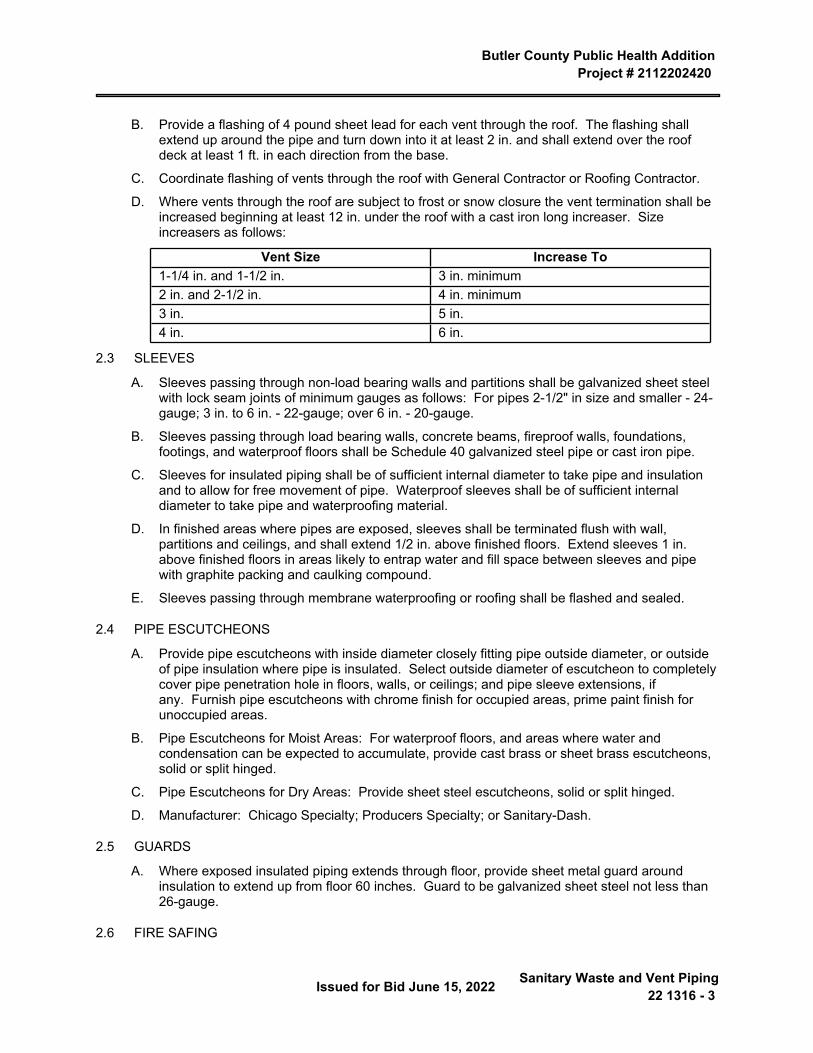
Butler County Public Health Addition Project # 2112202420
Issued for Bid June 15, 2022 Sanitary Waste and Vent Piping22 1316 - 3
B. Provide a flashing of 4 pound sheet lead for each vent through the roof. The flashing shall extend up around the pipe and turn down into it at least 2 in. and shall extend over the roof deck at least 1 ft. in each direction from the base.
C. Coordinate flashing of vents through the roof with General Contractor or Roofing Contractor.
D. Where vents through the roof are subject to frost or snow closure the vent termination shall be increased beginning at least 12 in. under the roof with a cast iron long increaser. Size increasers as follows:
Vent Size Increase To1-1/4 in. and 1-1/2 in. 3 in. minimum2 in. and 2-1/2 in. 4 in. minimum3 in. 5 in.4 in. 6 in.
2.3 SLEEVES
A. Sleeves passing through non-load bearing walls and partitions shall be galvanized sheet steel with lock seam joints of minimum gauges as follows: For pipes 2-1/2" in size and smaller - 24-gauge; 3 in. to 6 in. - 22-gauge; over 6 in. - 20-gauge.
B. Sleeves passing through load bearing walls, concrete beams, fireproof walls, foundations, footings, and waterproof floors shall be Schedule 40 galvanized steel pipe or cast iron pipe.
C. Sleeves for insulated piping shall be of sufficient internal diameter to take pipe and insulation and to allow for free movement of pipe. Waterproof sleeves shall be of sufficient internal diameter to take pipe and waterproofing material.
D. In finished areas where pipes are exposed, sleeves shall be terminated flush with wall, partitions and ceilings, and shall extend 1/2 in. above finished floors. Extend sleeves 1 in. above finished floors in areas likely to entrap water and fill space between sleeves and pipe with graphite packing and caulking compound.
E. Sleeves passing through membrane waterproofing or roofing shall be flashed and sealed.
2.4 PIPE ESCUTCHEONS
A. Provide pipe escutcheons with inside diameter closely fitting pipe outside diameter, or outside of pipe insulation where pipe is insulated. Select outside diameter of escutcheon to completely cover pipe penetration hole in floors, walls, or ceilings; and pipe sleeve extensions, if any. Furnish pipe escutcheons with chrome finish for occupied areas, prime paint finish for unoccupied areas.
B. Pipe Escutcheons for Moist Areas: For waterproof floors, and areas where water and condensation can be expected to accumulate, provide cast brass or sheet brass escutcheons, solid or split hinged.
C. Pipe Escutcheons for Dry Areas: Provide sheet steel escutcheons, solid or split hinged.
D. Manufacturer: Chicago Specialty; Producers Specialty; or Sanitary-Dash.
2.5 GUARDS
A. Where exposed insulated piping extends through floor, provide sheet metal guard around insulation to extend up from floor 60 inches. Guard to be galvanized sheet steel not less than 26-gauge.
2.6 FIRE SAFING
Butler County Public Health Addition Project # 2112202420
Sanitary Waste and Vent Piping 22 1316 - 4 Issued for Bid June 15, 2022
A. Metal piping and sleeves passing through floors, roof, partitions and fire walls, shall be provided with firestop by packing space between pipe and sleeve with UL listed non-sag and self-leveling fire safing insulation per manufacturer's instructions.
B. Plastic piping passing through fire rated floors and fire rated walls shall be provided with firestop by providing intumescent wrap strip around the pipe, enclosed in steel collar attached to structure.
C. Cracks, Voids, or Holes Up to 4" Diameter: Use non-sag or self-leveling putty or caulking, one-piece intumescent elastomer, non-corrosive to metal, compatible with synthetic cable jackets, and capable of expanding 10 times when exposed to flame or heat, UL listed.
D. Openings 4" or Greater: Use sealing system capable of passing 3-hour fire test in accordance with ASTM E814, consisting of wall wrap or liner, partitions, and end caps capable of expanding when exposed to temperatures of 250 to 350oF (121 to 177oC), UL listed.
E. Seal all holes or voids made by penetrations to ensure an effective barrier against smoke, fire, toxic and combustible gases.
F. Unless protected, from possible loading or traffic, install firestopping materials in floors having void openings or four (4) inches or more to support the same floor load requirements.
G. Manufacturer: Subject to compliance with requirements, provide non-sag and self-leveling fire barrier caulk, wrap/strip, moldable putty and sheet forms of one of the following:
1. 3M Brand.2. Flame Stop.3. Dow Corning.4. Metacaulk.
2.7 MECHANICAL SLEEVE SEALS
A. Modular mechanical type, consisting of interlocking synthetic rubber links shaped to continuously fill annular space between pipe and sleeve, connected with bolts and pressure plates which cause rubber sealing elements to expand when tightened, providing watertight seal and electrical insulation.
B. Manufacturer: Thunderline.
PART 3 EXECUTION
3.1 INSTALLATION
A. Install underground building drains as shown and in accordance with the Uniform Plumbing Code. Lay underground building drains beginning at low point of systems, true to grades and alignment indicated with unbroken continuity of invert. Place bell ends of piping facing upstream. Install required gaskets in accordance with manufacturer's recommendations for use of lubricants, cements, and other special installation requirements. Clean interior of piping of dirt and other superfluous material as work progresses. Maintain swab or drag in line and pull past each joint as it is completed. Place plugs in ends of uncompleted piping at end of day or whenever work stops.
B. Follow indicated lines generally, but make exact layout on the job to work actual fitting dimensions, align piping, and avoid interference. Provide proper support to maintain uniform fall of 1/4 in. per ft. for lines 3 in. and smaller and 1/8 in. per ft. for lines larger than 3 inches. Protect openings against the entrance of dirt.
Butler County Public Health Addition Project # 2112202420
Issued for Bid June 15, 2022 Sanitary Waste and Vent Piping22 1316 - 5
C. No soil or waste pipe shall be covered by earth or concealed by construction without first being proven free of leaks by means of a hydrostatic water test of no less than 10-feet of head or pneumatic air test of no less than 5 PSI. Pressure shall be held constant for a period of not less than 15 minutes before begining inspection or 15 minutes without the addition of air. Plastic pipe shall not be tested by air.
D. Install vents in practical alignment and supported with constant pitch back to the drainage system, concealed from finished spaces, unless shown or directed otherwise.
E. Soil, waste and vent connections to fixtures shall be accurately located and concealed from finished spaces, unless shown otherwise.
F. Refer to Division 31 - Earthwork for excavating, trenching, and backfilling requirements.
G. Contractor shall verify existing tie-in invert elevations of sanitary sewer piping prior to installation of new piping. Coordinate the site sewer tie-in invert elevation with the site utility contractor. Existing tie-in inverts that are discovered to be different from the information on the bid documents shall be reported to the General Contractor or Construction Manager and the Engineer immediately.
H. Install no-hub couplings and uniformly tighten clamps to manufacture's recommended torque specifications. No-hub coupling joints shall be properly supported so as to not be exposed to bending.
3.2 SLEEVES
A. Install sleeves for piping passing through floors, roof, walls, concrete beams, and foundations.
B. Install fire-proofing per manufacturer's written instructions.
3.3 ESCUTCHEONS
A. Install escutcheons for pipes entering finished spaces.
3.4 MECHANICAL SLEEVE SEAL INSTALLATION
A. Install mechanical sleeve seals at all pipe penetrations through foundations below grade.
B. Loosely assemble rubber links around pipe and bolts and pressure plates located under each bolt head and nut. Push into sleeve and center. Tighten bolts until links have expanded to form watertight seal.
3.5 PIPE PENETRATIONS
A. Penetrations shall be free of debris and dirt. Dam the penetration (when required) with an acceptable material. Apply fire stop material to the penetration per manufacturer's installation instructions. Use a caulking gun, putty knife or other normal trade tools. Remove damming materials where necessary after cure. Clean up with Xylene.
3.6 FIRE SAFING
A. Install fire safing at all penetrations through walls, floors, etc. per manufacturer's installation instructions as required to meet UL listing.
3.7 TESTING AND CLEANING
A. Provide labor, materials, facilities, and administration required to conduct the tests required under this section. Tests which fail to meet the specified performance shall be retested at no expense to the Owner. Repair all defective installations.
Butler County Public Health Addition Project # 2112202420
Sanitary Waste and Vent Piping 22 1316 - 6 Issued for Bid June 15, 2022
B. Flush out piping system with clean water before proceeding with required tests. Inspect each run of each system for completion of joints, supports and accessory items.
C. Testing shall be done in compliance with the Uniform Plumbing Code and to the satisfaction of the Authorities Having Jurisdiction.
D. Perform final testing after all fixtures have been set and all traps have been filled with water.
E. Hydraulic Water Testing:
1. Hydraulically pressure test each section or segment of the soil, waste and vent system prior to backfilling, encasing, enclosing or otherwise preventing visual observation of the section or segment being tested or access to repair if needed.
2. The system and all joints shall be tested with no less than 10 feet head of water pressure. Top of test standpipe to be filled with water shall be a minimum of 10 feet above the highest point of section being tested.
3. The water shall be kept in the tested system or sub-section for not less than 15 minutes before inspection for leakage begins.
4. All leaks shall be promptly repaired by replacing damaged or defective components with new parts and system shall be re-tested, repeating repair and re-testing steps as-needed, without additional cost to the Owner, until system is certified tight and leak free.
F. Pneumatic Air Pressure Testing:
1. Plastic piping shall not be tested with air. Do not overpressurize the system beyond maximum rating.
2. Pneumatically pressure test with air each section or segment of the soil, waste and vent system prior to backfilling, encasing, enclosing or otherwise preventing visual observation of the section or segment being tested or access to repair if needed.
3. The system and all joints shall be tested using an air compressor and pressure gauge or manometer testing apparatus.
4. Fill tested system with air to a uniform, stabilized gauge pressure of 5 PSI. The system shall be held at the test pressure without the addition of air for a period of not less than 15 minutes.
5. All leaks shall be promptly repaired by replacing damaged or defective components with new parts and system shall be re-tested, repeating repair and re-testing steps as-needed, without additional cost to the Owner, until system is certified tight and leak free.
END OF SECTION 22 1316
Butler County Public Health AdditionProject # 2112202420
Issued for Bid June 15, 2022 Sanitary Waste Piping
Specialties22 1319 - 1
SECTION 22 1319 SANITARY WASTE PIPING SPECIALTIES
PART 1 GENERAL
1.1 SECTION INCLUDES
A. Provide equipment, materials, labor and supervision neccessary to install soil, waste and vent system.
1.2 CODES AND STANDARDS
A. Local and/or State Plumbing, Mechanical and Building Codes
B. Uniform Plumbing Code
C. International Mechanical Code
D. NFPA Codes and Standards
1.3 SUMMARY
A. This Section includes the following sanitary drainage piping specialties:
1. Floor drains.2. Cleanouts.3. Floor sinks4. Trench drains5. Miscellaneous sanitary drainage piping specialties.
1.4 DEFINITIONS
A. ABS: Acrylonitrile-butadiene-styrene plastic.
B. FRP: Fiberglass-reinforced plastic.
C. HDPE: High-density polyethylene plastic.
D. PE: Polyethylene plastic.
E. PP: Polypropylene plastic.
F. PVC: Polyvinyl chloride plastic.
1.5 SUBMITTALS
A. Product Data: For each type of product indicated, include rated capacities, operating characteristics, and accessories.
B. Installation, Operations and Maintenance data. Include signed copies of certified testing results reports.
1.6 QUALITY ASSURANCE
A. Drainage piping specialties shall bear label, stamp, or other markings of specified testing agency.
Butler County Public Health Addition Project # 2112202420
Sanitary Waste Piping Specialties 22 1319 - 2
Issued for Bid June 15, 2022
B. Comply with NSF 14, "Plastics Piping Components and Related Materials," for plastic sanitary piping specialty components.
PART 2 PRODUCTS
2.1 CLEANOUTS
A. General:
1. Floor:
a. In floors of finished areas - epoxy coated, cast iron caulking ferrule for soil pipe hub with brass countersunk plug and cast brass round flush access cover with polished top. Furnish carpet flange and cover and cleanout ID marker for all carpeted areas.
b. In floors of unfinished areas - epoxy coated, cast iron with tapered body for caulking into soil pipe hub, with brass countersunk plug.
2. Wall:
a. In walls of finished areas - Gas and water tight bronze tapered seat, raised head plug, iron pipe size (IPS) male threads and round polished stainless steel cover plate with countersunk stainless steel cover screw. Provide with caulking ferrule where installed in cast iron soil pipe.
b. In walls of unfinished areas - Gas and water tight bronze tapered seat, raised head, iron pipe size (IPS) male threads. Provide with caulking ferrule where installed in cast iron soil pipe.
B. Manufacturers: Subject to compliance with requirements, provide clean outs by one of the following:
1. Zurn Plumbing Products Group2. J.R. Smith3. Wade4. Watts Drainage Products Inc.5. Engineer approved equivalent
2.2 FLOOR DRAINS
A. General:
1. Body: Floor and shower drains shall be epoxy coated cast iron with bottom outlet, convertible membrane clamp, adjustable collar with seepage slots.
2. Strainer: Polished heavy duty vandal-proof secured polished nickel bronze strainer and removable sediment bucket.
3. End Connections: hub and spigot, hubless, or threaded.B. Sizes: Refer to Project Drawings and Schedules.
C. Traps and Seals:
1. Drains without integral traps shall have service weight cast iron P traps.2. Provide trap primers on all floor drains and on other drains as shown on Drawings.
Butler County Public Health Addition Project # 2112202420
Issued for Bid June 15, 2022 Sanitary Waste Piping
Specialties22 1319 - 3
D. Seepage Pans:
1. Provide seepage pans of four pound sheet lead or Chloraloy 240 plastic at least 3' -0'' square for all floor drains over open space. Lead, if used, shall be thoroughly coated with asphaltum before it is placed in contact with concrete or concrete fill is poured over it.
2. Provide seepage pans of four-pound sheet lead or Chloraloy 240 plastic to cover total area of showers over open spaces. Pan shall turn up at ends at least 9 inches and corners shall be folded and properly sealed. Lead, if used, shall be thoroughly coated with asphaltum before it is placed in contact with concrete or concrete fill is poured over it
3. Flashing clamps and auxiliary drainage rims shall be provided for all drains that are to receive seepage pans.
E. Manufacturers: Subject to compliance with requirements, provide clean outs by one of the following:
1. Zurn Plumbing Products Group2. J.R. Smith3. Wade4. Watts Drainage Products Inc.5. Engineer approved equivalent
2.3 FLOOR SINKS
A. General:
1. Body: Floor sinks shall be cast iron body with white acid resisting porcelain interior and top, bottom outlet, seepage flange with seepage holes, and membrane clamping collar.
2. Strainer: Removable bottom anti-splash dome, white ABS.3. Grate: Secured, 1/2 open, medium duty with slotted openings.4. End Connections: hub and spigot, hubless, or threaded.
B. Sizes: Refer to Project Drawings and Schedules.
C. Traps and Seals:
1. Drains without integral traps shall have service weight cast iron P traps.2. Provide trap primers on all floor sinks and on other drains as shown on Drawings.
D. Manufacturers: Subject to compliance with requirements, provide clean outs by one of the following:
1. Zurn Plumbing Products Group2. J.R. Smith3. Wade4. Watts Drainage Products Inc.5. Engineer approved equivalent
2.4 TRENCH DRAINS
A. General:
1. ASME A112.6.3 - compliant floor and trench Drains.
Butler County Public Health Addition Project # 2112202420
Sanitary Waste Piping Specialties 22 1319 - 4
Issued for Bid June 15, 2022
B. Construction:
1. Epoxy coated cast iron with vertically and horizontally adjustable bottom outlet and anchor flange.
2. 0% water absorbent high density polyethylene (HDPE) with bottom outlet and anchor flange.
3. Membrane Clamping Device: Required.4. Seepage Pan: Required5. Strainer: Bottom dome and Removable stainless steel basket.6. Trap: Cast iron standard P-trap .
C. Grating: Vandal proof reinforced medium duty slotted, class A, polished nickel bronze grating.
D. Manufacturers: Subject to compliance with requirements, provide a comparable product by one of the following:
1. Josam Company2. Jay R. Smith Mfg. Co.3. Mifab, Inc.4. Tyler Pipe; Wade Div.5. Watts Drainage Products Inc.6. Zurn Plumbing Products Group7. Engineer approved equivalent
2.5 MISCELLANEOUS SANITARY DRAINAGE PIPING SPECIALTIES
A. Deep-Seal Traps
1. Description: Epoxy coated cast iron, with inlet and outlet matching connected piping and cleanout trap-seal primer valve connection.
2. Size: Same as connected waste piping.
a. NPS 2 (DN 50): 4-inch- (100-mm-) minimum water seal.
b. NPS 2-1/2 (DN 65) and Larger: 5-inch- (125-mm-) minimum water seal.
B. Air-Gap Fittings
1. Description: Epoxy coated cast iron body, ASME A112.1.2, designed to ensure fixed, positive air gap between installed inlet and outlet piping.
2. Size: Outlet shall be same size as connected waste piping and with inlet large enough for associated indirect waste piping. Unless noted otherwise the inlet to the air gap fitting shall be a larger size than the discharge of the piping leading into it.
C. Expansion Joints
1. Description: ASME A112.21.2M compliant. Cast iron body with bronze sleeve, packing and gland.
2. End Connections: hub and spigot, hubless, or threaded. Match piping connections.3. Size: Same as connected soil, waste, or vent piping.
2.6 FLASHING MATERIALS
Butler County Public Health Addition Project # 2112202420
Issued for Bid June 15, 2022 Sanitary Waste Piping
Specialties22 1319 - 5
A. Lead Sheet: ASTM B 749, Type L51121, copper bearing, with the following minimum weights and thicknesses, unless otherwise indicated:
1. General Use: 4.0-lb/sq. ft. (20-kg/sq. m), 0.0625-inch (1.6-mm) thickness.2. Vent Pipe Flashing: 3.0-lb/sq. ft. (15-kg/sq. m), 0.0469-inch (1.2-mm) thickness.3. Burning: 6-lb/sq. ft. (30-kg/sq. m), 0.0938-inch (2.4-mm) thickness.
B. Copper Sheet: ASTM B 152/B 152M, of the following minimum weights and thicknesses, unless otherwise indicated:
1. General Applications: 12 oz./sq. ft. (3.7 kg/sq. m or 0.41-mm thickness).2. Vent Pipe Flashing: 8 oz./sq. ft. (2.5 kg/sq. m or 0.27-mm thickness).
C. Zinc-Coated Steel Sheet: ASTM A 653/A 653M, with 0.20 percent copper content and 0.04-inch (1.01-mm) minimum thickness, unless otherwise indicated. Include G90 (Z275) hot-dip galvanized, mill-phosphatized finish for painting if indicated.
D. Elastic Membrane Sheet: ASTM D 4068, flexible, chlorinated polyethylene, 40-mil (1.01-mm) minimum thickness.
E. Fasteners: Metal compatible with material and substrate being fastened.
F. Metal Accessories: Sheet metal strips, clamps, anchoring devices, and similar accessory units required for installation; matching or compatible with material being installed.
G. Solder: ASTM B 32, lead-free alloy.
H. Bituminous Coating: SSPC-Paint 12, solvent-type, bituminous mastic.
2.7 OIL INTERCEPTORS
A. Oil Interceptors
1. Subject to compliance with requirements, provide a comparable product by one of the following:
a. Josam Company; Josam Div.
b. Smith, Jay R. Mfg. Co.; Division of Smith Industries, Inc.
c. Watts Drainage Products Inc.
d. Zurn Plumbing Products Group; Specification Drainage Operation.
2. Type: Factory-fabricated interceptor for separating and removing light oil from wastewater.
3. Body Material: Cast iron or steel or Plastic.4. Interior Lining: Corrosion resistant enamel or Not required.5. Exterior Coating: Corrosion restant enamel or Not required.6. End Connections: Flanged, Hub, or Threaded.7. Cleanout: Integral or Field installed on outlet.8. Mounting: Above floor, Recessed in acid resistant, coated steel frame and cradle, or
Recessed, flush with floor.9. Flow-Control Fitting: Not required or Required.10. Oil Storage Tank: Coordinate with Division 23 "Facility Fuel-Oil Piping"
Butler County Public Health Addition Project # 2112202420
Sanitary Waste Piping Specialties 22 1319 - 6
Issued for Bid June 15, 2022
PART 3 EXECUTION
3.1 INSTALLATION
A. Refer to Division 22 Section "Common Work Results for Plumbing" for piping joining materials, joint construction, and basic installation requirements.
B. Install wood-blocking reinforcement for wall-mounting-type specialties.
C. Install cleanouts in aboveground piping and building drain piping according to the following, unless otherwise indicated:
1. Size same as drainage piping up to NPS 4 (DN 100). Use NPS 4 (DN 100) for larger drainage piping unless larger cleanout is indicated.
2. Locate at each change in direction of piping greater than 45 degrees.3. Locate at minimum intervals of 50 feet (15 m) for piping NPS 4 (DN 100) and smaller and
100 feet (30 m) for larger piping.4. Locate at base of each vertical soil and waste stack.
D. For floor cleanouts for piping below floors, install cleanout deck plates with top flush with finished floor.
E. For cleanouts located in concealed piping, install cleanout wall access covers, of types indicated, with frame and cover flush with finished wall.
F. Install floor drains at low points of surface areas to be drained. Set grates of drains flush with finished floor, unless otherwise indicated.
1. Position floor drains for easy access and maintenance.2. Set floor drains below elevation of surrounding finished floor to allow floor drainage. Set
with grates depressed according to the following drainage area radii:
a. Radius, 30 Inches (750 mm) or Less: Equivalent to 1 percent slope, but not less than 1/4-inch (6.35-mm) total depression.
b. Radius, 30 to 60 Inches (750 to 1500 mm): Equivalent to 1 percent slope.
c. Radius, 60 Inches (1500 mm) or Larger: Equivalent to 1 percent slope, but not greater than 1-inch (25-mm) total depression.
3. Install floor-drain flashing collar or flange so no leakage occurs between drain and adjoining flooring. Maintain integrity of waterproof membranes where penetrated.
4. Install individual traps for floor drains connected to sanitary building drain, unless otherwise indicated.
5. Install traps on plumbing specialty drain outlets. Omit traps on indirect wastes unless trap is indicated.
6. Install deep-seal traps on floor drains, and other waste outlets unless otherwise indicated.7. Provide trap primers on all floor drains and on other drains as shown on Drawings.
G. Install air-gap fittings on draining-type backflow preventers and on indirect-waste piping discharge into sanitary drainage system.
H. Install expansion joints on vertical stacks and conductors. Position expansion joints for easy access and maintenance.
Butler County Public Health Addition Project # 2112202420
Issued for Bid June 15, 2022 Sanitary Waste Piping
Specialties22 1319 - 7
I. Install oil interceptors, including trapping, venting, and flow-control fitting, according to authorities having jurisdiction and with clear space for servicing. Coordinate oil-interceptor storage tank and gravity drain with Division 23 Section "Facility Fuel-Oil Piping."
J. Install escutcheons at wall, floor, and ceiling penetrations in exposed finished locations and within cabinets and millwork. Use deep-pattern escutcheons if required to conceal protruding pipe fittings.
3.2 COORDINATION
A. Coordinate size and location of concrete bases. Cast anchor-bolt inserts into bases. Concrete, reinforcement, and formwork requirements are specified in Division 03.
B. Coordinate size and location of roof penetrations.
3.3 FLASHING INSTALLATION
A. Fabricate flashing from single piece unless large pans, sumps, or other drainage shapes are required. Join flashing according to the following if required:
1. Lead Sheets: Burn joints of lead sheets 6.0-lb/sq. ft. (30-kg/sq. m), 0.0938-inch (2.4-mm) thickness or thicker. Solder joints of lead sheets 4.0-lb/sq. ft. (20-kg/sq. m), 0.0625-inch (1.6-mm) thickness or thinner.
B. Install sheet flashing on pipes, sleeves, and specialties passing through or embedded in floors and roofs with waterproof membrane.
1. Pipe Flashing: Sleeve type, matching pipe size, with minimum length of 10 inches (250 mm), and skirt or flange extending at least 8 inches (200 mm) around pipe.
2. Sleeve Flashing: Flat sheet, with skirt or flange extending at least 8 inches (200 mm) around sleeve.
3. Embedded Specialty Flashing: Flat sheet, with skirt or flange extending at least 8 inches (200 mm) around specialty.
C. Set flashing on floors and roofs in solid coating of bituminous cement.
D. Secure flashing into sleeve and specialty clamping ring or device.
E. Install flashing for piping passing through roofs with counterflashing or commercially made flashing fittings, according to Division 07 Section "Sheet Metal Flashing and Trim."
F. Extend flashing up vent pipe passing through roofs and turn down into pipe, or secure flashing into cast-iron sleeve having calking recess.
G. Fabricate and install flashing and pans, sumps, and other drainage shapes.
3.4 FIELD QUALITY CONTROL
A. Tests and Inspections:
1. Leak Test: After installation, charge system and test for leaks. Repair leaks and retest until no leaks exist.
2. Test and adjust controls and safeties. Replace damaged and malfunctioning controls and equipment.
3.5 PROTECTION
A. Protect drains during remainder of construction period to avoid clogging with dirt or debris and to prevent damage from traffic or construction work.
Butler County Public Health Addition Project # 2112202420
Sanitary Waste Piping Specialties 22 1319 - 8
Issued for Bid June 15, 2022
B. Place plugs in ends of uncompleted piping at end of each day or when work stops.
END OF SECTION 22 1319
Butler County Public Health AdditionProject # 2112202420
Issued for Bid June 15, 2022 Plumbing Equipment22 3000 - 1
SECTION 22 3000 PLUMBING EQUIPMENT
PART 1 GENERAL
1.1 SECTION INCLUDES
A. In-line circulator pumps.
B. Cooling condensate removal pumps.
1.2 REFERENCE STANDARDS
A. UL 778 - Standard for Motor-Operated Water Pumps Current Edition, Including All Revisions.
1.3 SUBMITTALS
A. See Section 01 3000 - Administrative Requirements, for submittals procedures.
B. Product Data:
1. Provide dimension drawings of water heaters indicating components and connections to other equipment and piping.
2. Indicate pump type, capacity, power requirements.3. Provide certified pump curves showing pump performance characteristics with pump and
system operating point plotted. Include NPSH curve when applicable.4. Provide electrical characteristics and connection requirements.
1.4 DELIVERY, STORAGE, AND HANDLING
A. Provide temporary inlet and outlet caps. Maintain caps in place until installation.
PART 2 PRODUCTS
2.1 IN-LINE CIRCULATOR PUMPS
A. Manufacturers:
1. Armstrong Fluid Technology: www.armstrongfluidtechnology.com/#sle.2. Bell & Gossett, a xylem brand; www.bellgossett.com/#sle.3. Sterling SIHI GmbH; www.sterlingsihi.com/#sle.4. Taco..
B. Casing: Bronze, rated for 125 psig (860 kPa) working pressure, with stainless steel rotor assembly.
C. Impeller: Bronze.
D. Shaft: Alloy steel with integral thrust collar and two oil lubricated bronze sleeve bearings.
E. Seal: Carbon rotating against a stationary ceramic seat.
F. Drive: Flexible coupling.
Butler County Public Health Addition Project # 2112202420
Plumbing Equipment 22 3000 - 2 Issued for Bid June 15, 2022
2.2 COOLING CONDENSATE REMOVAL PUMPS
A. Manufacturers:
1. Franklin Electric Company; www.franklin-electric.com/#sle.2. Liberty Pumps Inc; www.libertypumps.com/#sle.
B. Construction: Commercial grade, nonferrous pump with stainless steel shaft, integral discharge check valve, integral float switch, safety switch, thermoplastic reservoir, motor assembly, and power cord with ground.
C. Safety: UL 778.
PART 3 EXECUTION
3.1 INSTALLATION
A. Install plumbing equipment in accordance with manufacturer's instructions, as required by code, and complying with conditions of certification, if any.
B. Coordinate with plumbing piping and related fuel piping work to achieve operating system.
C. Pumps:
1. Ensure pumps operate at specified system fluid temperatures without vapor binding and cavitation, are non-overloading in parallel or individual operation, and operate within 25 percent of midpoint of published maximum efficiency curve.
2. Provide electrical interlocking from cooling condensate pump safety switch to associated HVAC unit(s) furnished under other Sections.
END OF SECTION
Butler County Public Health AdditionProject # 2112202420
Issued for Bid June 15, 2022 Electric Domestic Water Heaters22 3300 - 1
SECTION 22 3300 ELECTRIC DOMESTIC WATER HEATERS
PART 1 GENERAL
1.1 SECTION INCLUDES
A. Provide materials, equipment, tools, labor and supervision necessary to install Electric Domestic Water Heaters as required by the Drawings and this Section.
1.2 CODES AND STANDARDS
A. ASHRAE/ANSI/IES 90.1 - Energy Efficiency for Buildings Except Low-Rise Residential Buildings
B. IEEC - International Energy Conservation Code
C. ASME Boiler and Pressure Vessel Code
D. NFPA/NEC 70 - National Electrical Code
E. UPC - Uniform Plumbing Code
F. IMC - International Mechanical Code
G. Local and/or State Plumbing, Mechanical and Building Codes
H. NFPA Codes and Standards
I. IAPMO, NSF and U.L. 174 or 1453 Listed
J. Federal Energy Conservation Standards (2015)
K. Any product used for dispensing potable water shall meet NSF 61 and NSF 372 testing standards. Third party testing shall be required.
1.3 SUBMITTALS
A. Product Data: Submit product, dimensional, efficiency and performance data.
B. Wiring Diagrams: Submit manufacturer's electrical requirements for power supply wiring to water heaters. Submit manufacturer's ladder-type wiring diagrams for interlock and control wiring. Clearly differentiate between portions of wiring that are factory-installed and portions to be field-installed.
C. Installation, Operations and Maintenance data. Include wiring diagrams.
PART 2 PRODUCTS
2.1 ELECTRIC DOMESTIC STORAGE TANK WATER HEATERS
A. Tank: Steel, glasslined, vermin-proof CFC foam insulation, stainless steel core anode corrosion protection. Outer jacket shall be baked enamel finish. 150 PSI rated working pressure.
B. Heating Elements: Dual, medium wattage density, zinc plated copper sheath heating elements.
C. Furnish with brass drain valve, thermometer and pressure gauges, and ASME rated T&P relief valve in accordance with State and local codes, regulations and ordinances.
Butler County Public Health Addition Project # 2112202420
Electric Domestic Water Heaters 22 3300 - 2
Issued for Bid June 15, 2022
D. Electrical and Controls:
1. Provide NEMA 4 electrical junction box with terminal block for wiring connections.E. Drain Pan: Furnish corrosion resistant material, water tight drain pan with 3/4 inch min. sized
drain piping beneath water heaters.
F. Warranty: 6-year tank and parts warranty.
G. Water heater performance shall be as schedule on Drawings. Refer Schedules for energy efficiency factors, first hour ratings, recovery ratings, and storage capacity information.
H. Acceptable Manufacturers: Subject to compliance with requirements, provide equipment by one of the following:
1. A.O Smith2. State3. Lochinvar4. Rudd5. Patterson Kelly6. Engineer approved equivalent
2.2 EXPANSION - COMPRESSION TANKS
A. Description: Steel, 150 psig max. pressure and 200 degree F max. temperature rated tank constructed with welded joints and factory installed butyl rubber diaphragm and rigid, mechanically bonded polypropylene liner. Include 20 psig air factory pre-charge.
B. Construction:
1. Tappings: Factory fabricated stainless steel, welded to tank before testing and labeling. Include ASME B1.20.1 pipe threads.
2. Interior Finish: NSF 61 compliant barrier materials for potable water systems including fittings and outlets. All wetted components shall be of FDA approved materials.
3. Air Charging Valve: Factory installed, Schrader valve for field charging.C. Capacity:
1. Tank Capacity: 4.5 gallons minimum.2. Acceptance Volume: 3.2 gallons at 20 psig air side pressure.3. Air Pre-charge Pressure: 20 psi. Field adjust to system operating pressure.
PART 3 EXECUTION
3.1 INSTALLATION
A. Make hot and cold water piping connections including thermal checks.
B. Route T & P relief valve piping to within 6 inches of floor.
END OF SECTION 22 3300
Butler County Public Health AdditionProject # 2112202420
Issued for Bid June 15, 2022 Plumbing Fixtures22 4000 - 1
SECTION 22 4000 PLUMBING FIXTURES
PART 1 GENERAL
1.1 SECTION INCLUDES
A. Provide fixtures, trim, accessories, labor, tools and supervision necessary to furnish and install plumbing fixtures as required by the drawings and this Section.
1.2 FIXTURE SCHEDULE
A. Fixtures, trim, and accessories shall be of type and model numbers as scheduled on the drawings.
1.3 CODES AND STANDARDS
A. IBC - International Building Code
B. UPC - Uniform Plumbing Code
C. PDI Compliance: Comply with standards established by PDI pertaining to plumbing fixture supports.
D. ADA Compliance: Construct and install barrier-free plumbing fixtures in accordance with ADA and ANSI A117.1 requirements.
E. Local and/or State Plumbing, Mechanical and Building Codes
F. NFPA Codes and Standards
G. IAPMO, NSF and U.L.
H. Any product used for dispensing potable water shall meet NSF 61 and NSF 372 testing standards. Third party testing shall be required.
1.4 SUBMITTALS
A. Submit Product Data which shall include product description, manufacturer, model, dimensions, size, rough-in requirements, connections to other equipment, construction materials and finishes, trim, accessory schedule, and performance data for each type of fixture.
B. Submit manufacturers Installation Operation and Maintenance instructions. Include signed copies of certified testing reports.
C. Submit to the General Contractor, cut-out trim plate for sinks which are to be installed in counter tops.
PART 2 PRODUCTS AND QUALIFICATIONS
2.1 MANUFACTURERS
A. Subject to compliance with requirements, provide products manufactured by one of the following, as listed for each type of fixture, or an Engineer-approved equivalent:
1. Vitreous China and Cast Iron Enameled Fixtures: American Standard, Crane, Kohler, Eljer, and Zurn.
Butler County Public Health Addition Project # 2112202420
Plumbing Fixtures 22 4000 - 2 Issued for Bid June 15, 2022
2. Water Closet and Urinal Flush Valves: Sloan or Zurn3. Stainless Steel Sinks: Elkay or Just Mfg.4. Trim: Chicago Faucets, Delta Commercial, T&S Brass Works, or Sloan5. Drinking Fountains and Water Coolers: Elkay, Halsey Taylor, or Oasis6. Shower Valves: Chicago Faucets, Delta Commercial, Sloan, or Bradley7. Fixture Carriers: Zurn, Wade, Josam, or J.R Smith8. Janitor Sinks and Shower Bases: Crane-Fiat, Stern-Williams, or Swan9. Toilet Seats: Bemis, Church, or Olsonite
2.2 VITREOUS FIXTURES
A. Vitreousware shall be non-absorbent, even color, un-warped, two-fired vitreous china, grade A as rated by the Bureau of Standards.
B. Enameled cast iron fixtures shall have the enamel fused with the iron to provide a hard acid-resisting enameled finish.
C. Vitreous fixtures shall be white, except where other colors are called for in schedule.
D. Bathtubs shall have slip-resistant surface.
2.3 FLUSH VALVES
A. Flush valves for handicapped fixtures shall be installed in compliance with ADA requirements and shall be installed with flush valve control mounted on wide side of toilet.
B. Flush valves shall be installed with angle stop and vacuum breaker.
2.4 STAINLESS STEEL SINKS
A. Stainless steel sinks shall be fabricated from 18-gauge nickel-bearing type 302 stainless steel, with satin finish, and sound deadening treatment.
B. Where non-self rimming sinks are specified, furnish sinks with Hudee mounting rim.
C. Provide sinks with compression style clip and bolt mounting hardware.
2.5 TRIM
A. Trim shall include: Supply pipes, stop valves, faucets, tail pieces, strainers, wastes, traps, and floor and wall escutcheon plates which shall be brass. Exposed trim shall be chrome-plated.
B. Stop valves shall be compression type with loose key handle control.
C. P-traps shall be chrome-plated, adjustable cast brass with cleanout plug.
D. Faucets shall contain standardized interchangeable operating units for both hand-closing and self-closing types, closing with the pressure of the water and containing a stamped Monel metal seat.
2.6 ELECTRIC WATER COOLERS
A. Refer to Drawings and Schedules.
B. Furnish one-piece silver impregnated charcoal, NSF approved, inline water filter for all electric water coolers. Furnish an additional filter element for each Electric Water Cooler installed.
Butler County Public Health Addition Project # 2112202420
Issued for Bid June 15, 2022 Plumbing Fixtures22 4000 - 3
2.7 SHOWER VALVES
A. Shower valves shall be mixing valve type, pressure balancing, with integral stops. Refer to Plumbing Fixture Schedule on Drawings for manufacturer and model numbers.
2.8 AERATORS
A. Provide aerators of types approved by Health Departments having jurisdiction. Maximum flow to be 0.5 gpm in compliance with Energy Policy Act of 2005 and ASME/ANSI Standard A112.18.1M provide restrictive aerator as required.
B. Comply with additional fixture requirements contained in fixture Schedule as shown on Drawings.
2.9 FIXTURE CARRIERS
A. Provide cast-iron supports for fixtures of graphitic gray iron, ductile iron, or malleable iron as indicated. Provide floor mounted carriers for wall mounted fixtures.
2.10 FIXTURE BOLT CAPS
A. Provide manufacturer's standard exposed fixture bolt caps finished to match fixture finish.
2.11 ESCUTCHEONS
A. Where fixture supplies and drains penetrate walls in exposed locations and within cabinetry, provide chrome plated sheet steel escutcheons with friction clips.
PART 3 EXECUTION
3.1 INSPECTION
A. Examine roughing-in work of potable water and waste piping systems to verify actual locations of piping connections prior to installing fixtures. Also examine floors and substrates, and conditions under which fixture work is to be accomplished. Correct any incorrect locations of piping, and other unsatisfactory conditions for installation of plumbing fixtures. Do not proceed with work until unsatisfactory conditions have been corrected in manner acceptable to Installer.
3.2 INSTALLATION
A. General: Install plumbing fixtures of types indicated where shown and at indicated heights; in accordance with fixture manufacturer's written instructions, roughing-in drawings, and with recognized industry practices. Ensure that plumbing fixtures comply with requirements of the Uniform Plumbing Code and Americans with Disability Act (ADA) Standards for Accessible Design pertaining to installation of plumbing fixtures.
B. Fasten plumbing fixtures securely to indicated supports or building structure and ensure that fixtures are level and plumb. Secure plumbing supplies behind or within wall construction so as to be rigid, and not subject to pull or push movement.
C. Install fixtures and make water supply, waste, and vent connections as indicated on drawings.
D. Set fixtures in center of stalls, between partitions where required. Dimensions for spacing shall be verified.
E. Setting shall be absolutely tight and rigid on proper ground. All fixtures shall be sealed to structures (walls, floors, etc.) with non-mildew silicone caulk.
Butler County Public Health Addition Project # 2112202420
Plumbing Fixtures 22 4000 - 4 Issued for Bid June 15, 2022
F. Fixtures shall be covered with paper glued in place after they are set to prevent damage during the balance of construction, at the conclusion of work the paper shall be removed and the fixtures properly cleaned.
G. The Contractor shall be responsible for the protection of the fixtures until acceptance by the Owner. Damaged fixtures shall be replaced at no additional cost to the Owner.
H. All fixtures and accessories for handicapped use shall be installed in compliance with ADA requirements.
I. Countertop mounted stainless steel sinks shall be installed using a compression style clip and bolt mount. Snap ring installations shall NOT be permitted.
3.3 FIELD QUALITY CONTROL
A. Upon completion of installation of plumbing fixtures and after units are water pressurized, test fixtures to demonstrate capability and compliance with requirements. When possible, correct malfunctioning units at the site, then retest to demonstrate compliance; otherwise, remove and replace with new units and proceed with retesting.
B. Inspect each installed unit for damage to finish. If feasible, restore and match finish to original at site; otherwise, remove fixture and replace with new unit. Feasibility and match to be judged by Architect/Engineer. Remove cracked or dented units and replace with new units.
3.4 ADJUSTING AND CLEANING
A. Clean plumbing fixtures, trim, and strainers of dirt and debris upon completion of installation.
B. Adjust water pressure at drinking fountains, faucets, shower valves, and flush valves to provide proper flow stream and specified gpm.
C. Adjust or replace washers to prevent leaks at faucets and stops.
END OF SECTION 22 4000
Butler County Public Health AdditionProject # 2112202420
Issued for Bid June 15, 2022 Common Work Results for
HVAC23 0500 - 1
SECTION 23 0500 COMMON WORK RESULTS FOR HVAC
PART 1 GENERAL
1.1 SECTION INCLUDES
A. The work shall include the furnishings of systems, equipment and materials specified in this Division and as called for on the Mechanical Drawings to include supervision, quality control, operation, methods and labor for the fabrication, installation, start-up and tests for the complete mechanical installation. The work shall also include the furnishing of necessary hoisting facilities to set materials and equipment in place and the furnishing of any scaffolding and transportation associated with this work.
B. Examine the project site and become familiar with existing conditions which will affect the work. Review the drawings and specifications of other trades and take note of conditions to be created which will affect the work. All conditions shall be considered in the preparation of bids; no additional compensation will be made on the behalf of this Contractor.
C. Provide labor necessary to demolish the existing mechanical system as shown on the drawings, as described in Part 3, Existing Conditions, or as required.
D. Where noted on the drawings or where called for in other sections of the specification, the Contractor for this division shall install equipment furnished by others, and shall make required service connections. Verify with the supplier of the equipment the requirements for the installation. This contractor shall be responsible for the removal and installation of railings, piping, ductwork, louvers, etc. as required to install new equipment. Coordinate shipping splits for all equipment provided by this contractor.
1.2 DAMAGE
A. The Contractor shall be responsible for damage to the work of other trades or to the building and its contents, caused by equipment installation.
1.3 PERMITS AND INSPECTIONS
A. Obtain and furnish necessary permits and inspection certificates for material and labor furnished. Permits and certificates shall be obtained from the proper inspection authorities. The cost of permits, certificates and fees required in connection with the installation shall be borne by the Contractor, unless otherwise noted in the detailed contractual description preceding these specifications. Where applications are required for the procuring of utility services to the building, see that such application is properly filed with the utility, and that information required for such an application is presented to the extent and in the form required by the utility company.
1.4 CODES AND STANDARDS
A. Applicable provisions of the following codes and standards are hereby imposed on a general basis for the mechanical work (in addition to specific applications specified by individual work sections of these specifications):
1. ASHRAE/IES 90.1 - 2010 Code for Energy Efficiency2. ANSI Pressure Piping Standards (B31)3. ASHRAE Safety Code for Mechanical Refrigeration (ANSI B9.1)
Butler County Public Health Addition Project # 2112202420
Common Work Results for HVAC 23 0500 - 2
Issued for Bid June 15, 2022
4. AWWA Standards5. ASME Boiler and Pressure Vessel Code and State Boiler Code6. American Gas Association7. AWS Standards for Welding8. National Electrical Code9. Local and/or State Plumbing, Mechanical and Building Codes10. Occupational Safety and Health Act (OSHA)11. International Energy Conservation Code 201212. International Plumbing Code13. International Mechanical Code14. NFPA Standards and Pamphlets
B. If any work indicated on the drawings or specified herein conflicts in any way with any of the rules and regulations of the above authorities, the Contractor shall notify the Architect/Engineer in writing 72 hours before bids are opened. In the event the Contractor fails to notify the Architect/Engineer and changes are required by said conflicts, the Contractor shall make such changes as are required without additional cost to this Owner.
C. Installations must be safe in every respect, and must not create a condition which will be harmful to building occupants; to operating, installing or testing personnel; to workmen; or to the public. The contractor for each installation shall be solely responsible for providing installations which will meet these conditions. If the Contractor believes that the installation will not be safe for all parties, report these beliefs in writing to the Architect/Engineer before any equipment is purchased or work is installed, giving recommendations. The Architect/Engineer will work out required changes and adjustments in contract price where adjustments are warranted.
1.5 DRAWINGS
A. A complete set of drawings including civil, architectural, structural, mechanical, and electrical drawings shall be on the site at all times. Prior to installing any of the work, check the drawings for dimensions and see that the work does not interfere with clearance required for ceilings, beams, foundations, finished columns, pilasters, partitions and electrical equipment as shown on the drawings and details. After work is installed and it develops that interferences occur which have not been called to the Architect/Engineer's attention before the installation, the Contractor shall, at his own expense, make such changes in his work as directed by the Architect/Engineer.
B. The contract drawings for mechanical work are in part diagrammatic, intended to convey the scope of work and indicate general arrangement and approximate sizes and locations of equipment and materials. Where job conditions require reasonable changes in indicated locations and arrangement, the Contractor shall make such changes as directed by the Architect/Engineer, without additional cost to the Owner.
C. Because of the scale of the drawings, certain basic items such as pipe fittings, access panels, and sleeves may not be shown; but where such items are required by other sections of these specifications or where they are required by the nature of the work, they shall be furnished and installed. Rough-in dimensions and locations shall be verified with the supplier of equipment furnished by other trades, or by the Owner, prior to the time of roughing-in.
Butler County Public Health Addition Project # 2112202420
Issued for Bid June 15, 2022 Common Work Results for
HVAC23 0500 - 3
D. Equipment specification may not deal individually with minute items required such as components, parts, controls and devices which may be required to produce the equipment performance specified, or as required to meet the equipment warranties. Where such items are required, they shall be included by the supplier of the equipment, whether or not specifically called for.
E. The drawings and the specifications are cooperative and supplementary. It is the intent of both said drawings and specifications to cover all mechanical requirements in their entirety as nearly as possible. The Contractor shall closely check the drawings and specifications for any obvious errors or omissions and bring any such condition to the attention of the Architect/Engineer prior to the receipt of bids, in order to permit clarification by means of a mailed Addendum. If there is no question prior to the bid proposal date, the Architect/Engineer shall assume that the drawings and specifications are complete and correct and will expect the intent of said documents to be complied with, and the installation to be complete in all respects, according to said intent.
F. Locate equipment which must be serviced, operated or maintained in fully accessible positions. Minor deviations from the contract drawings may be made to allow for better accessibility, but changes of magnitude, or which involve extra cost, shall not be made without prior approval. Ample space shall be allowed for removal of parts that may require replacement or service in the future.
G. All valves, fire dampers, automatic dampers, smoke dampers, damper operators, reheat coils, etc. shall be accessible for maintenance purposes. Locate items carefully and coordinate with other trades so that each piece of equipment is accessible and functional. Items located above a non-accessible ceiling, chase, or soffit shall be accessible through an access door. Coordinate location of access doors with the general contractor.
1.6 RESPONSIBILITY
A. The Contractor's responsibility shall not end with the installation and connecting of the various apparatus. It shall include the services of an experienced superintendent, who shall be constantly in charge of the work, together with the qualified journeymen, helpers and laborers required to properly unload, install, connect, adjust, start, operate and test the work involved, including equipment and materials furnished by other trades or by the Owner, until such time as the entire mechanical installation functions properly in every detail.
1.7 COORDINATION
A. Coordinate the work with other trades prior to installation.
B. No piping, ducts or equipment foreign to the electrical equipment or architectural appurtenances shall be run over the top of any electrical panels or electrical equipment, in accordance with NEC 110-16 and 384-4. This does not prohibit sprinkler protection for the installation.
C. The determination of quantities of material and equipment required shall be made from the drawings. Schedules on the drawings and in the specifications are completed as an aid, but where discrepancies arise, it shall be the Contractor's responsibility to provide the required quantity.
D. Where the specifications state that equipment shall be furnished, installed or provided, it shall be understood to mean this Contractor shall furnish and install completely, unless it is specifically stated that the equipment is to be furnished and installed by others.
E. The Architect/Engineer reserves the right to determine space priority of the contractors in the event of interference between the piping and equipment of the various contractors. Conflicts
Butler County Public Health Addition Project # 2112202420
Common Work Results for HVAC 23 0500 - 4
Issued for Bid June 15, 2022
between the drawings and specifications, or between requirements set forth for the various trades, shall be called to the attention of the Architect/Engineer. If clarification is not asked for prior to the taking of bids, it will be assumed that none is required, and that the Contractor has submitted his bid in conformance with plans and specifications as issued and that no interference exists.
F. No piping, ducts or equipment foreign to an elevator hoistway and machine room shall be run inside the hoistway and machine room in accordance with NEC 620-37 and ASME A17.1, 102.2.
1.8 GUARANTEE AND MAINTENANCE
A. Materials and equipment shall be guaranteed to be free from defects and to be new equipment; no secondhand, used or salvaged equipment will be allowed.
B. Keep the entire portion of the work in repair, without additional cost to the Owner, so far as defects in workmanship, apparatus, material or construction are concerned for one (1) year from the date of final acceptance, except as otherwise specified herein.
C. Equipment, which fails to meet performance ratings as specified and shown on the drawings, shall be removed and replaced by new equipment that meets the specified requirements, without additional cost to the Owner.
D. Materials and workmanship shall be subject to the review of the Architect/Engineer, in whose presence various tests shall be made as required by these specifications.
PART 2 PRODUCTS
2.1 SUBMITTAL PROCESS
A. Submit shop drawings and catalog data for mechanical equipment specified in Division 23 in accordance with Division 01.
B. Submittal data for mechanical equipment shall consist of shop drawings and/or catalog cuts showing technical data necessary to evaluate the material or equipment to include dimensions, wiring diagrams, performance curves, rating, control sequence, and other descriptive data necessary to describe fully the item proposed and its operating characteristics. Shop drawings shall be submitted on equipment and materials as required by the specifications.
C. Approval of materials, including alternate or substitute items, shall be obtained in writing from the Architect/Engineer, verbal approval will not be considered binding.
D. Shop drawings shall be submitted and shall have been signed, checked, approved, and initialed by the Contractor prior to submittal to the Architect/Engineer. The Architect/Engineer will review shop drawings to aid in interpreting the plans and specifications, and will in so doing assume that the shop drawings conform to specified requirements set forth in this specification. The approval of the shop drawing by the Architect/Engineer does not relieve the Contractor of the responsibility of complying with elements of the specification. The name of the job, Architect/Engineer, location, and specification section shall appear on all pages of shop drawings. Equipment marks (such as EF-1, RTU-1) shall be indicated for each item.
E. At the completion of the job, furnish three (3) copies of parts lists, operating and maintenance instructions, and manuals organized and bound, in three books.
F. At the completion of the project, prepare and submit to the Owner record drawings showing the location of piping and ductwork. Drawing shall give accurate dimensions of such equipment for
Butler County Public Health Addition Project # 2112202420
Issued for Bid June 15, 2022 Common Work Results for
HVAC23 0500 - 5
future use by the Owner. This drawing shall be submitted as soon as work is completed and before authorization of final payment.
2.2 SUBCONTRACTORS AND MATERIALS
A. Submit to the Architect/Engineer for review, when requested, a list of subcontractors, materials and equipment proposed to be used. The list must be reviewed by the Architect/Engineer before this Contractor may enter into any subcontractual agreement. Equipment, materials, and devices, etc. shall be subject to the review of the Architect/Engineer, whether or not said items are herein specified.
2.3 STANDARDS OF MATERIALS AND WORKMANSHIP
A. Materials shall be new, complete with manufacturer's guarantee or warranty, and shall be as listed by Underwriters Laboratories (UL), Inc., Air Movement and Control Association (AMCA), American Gas Association (AGA), Air Conditioning and Refrigeration Institute (ARI), etc., if a standard has been established by that agency for the type of material.
B. Materials shall also comply with applicable standards of the National Electrical Manufacturer's Association, National Board of Fire Underwriters, National Fire Protection Association, National Safety Council, National Bureau of Standards, the National Electrical Code and the Williams-Steiger Occupational Safety and Health Act of 1970. Such standards are hereby made a part of these specifications.
C. Work shall be performed by workmen skilled in the particular craft, shall be executed in a workmanlike manner, and shall present a neat mechanical appearance when completed. Align, level and adjust equipment for satisfactory operation, and install so that connecting and disconnecting of piping and accessories can be made readily and so that parts are easily accessible for inspection, operation and maintenance. Methods and techniques of installation shall be subject to the review of the Architect/Engineer.
D. Materials shall be the standard product of a reputable manufacturer regularly engaged in the manufacture of the specific product. Materials of the same type of class shall be the products of one manufacturer. For example, fans shall be from the same manufacturer and pumps from the same manufacturer.
E. Materials shall be protected from damage, and stored indoors or protected from the weather at all times, unless other storage arrangements are approved by the Architect/Engineer.
F. Bearing lubrication fittings shall be as recommended by the manufacturer and shall be extended, where necessary, to an accessible location.
G. Material and equipment shall be installed in strict accordance with the manufacturer's recommendations.
2.4 MATERIAL SUBSTITUTIONS
A. Proposals as submitted shall be based on the products specifically named in the specification or on the drawings. Material or equipment by manufacturers other than those specified may be used only by permission of the Architect/Engineer. Such permission for substitution must be requested, in writingin accordance with Division 01.
B. The Architect/Engineer reserves the sole right for the approval of proposed material or equipment, and the phrase, "or approved equivalent", used in these specifications, or on the drawings, shall be interpreted to mean an equivalent approved by the Architect/Engineer.
Butler County Public Health Addition Project # 2112202420
Common Work Results for HVAC 23 0500 - 6
Issued for Bid June 15, 2022
C. Changes required by alternate equipment shall be made at no additional cost to the Owner; and costs incurred by other trades, public utilities or the Owner, as a result of the use of such equipment, shall be the responsibility of the Contractor.
D. Furnish to the Architect/Engineer, when requested, samples of proposed material or equipment substitutions. These samples shall remain with the Architect/Engineer as long as needed.
E. Identify the differences in alternate material or equipment as compared to that specified, and indicate the benefits to the project as a result of selecting the alternative.
F. The Architect/Engineer reserves the right to refuse approval of equipment which does not meet the specification, in their opinion, or of equipment for which no local experience of satisfactory service is available. The Architect/Engineer further reserves the right to reject equipment for which maintenance service and the availability of replacement parts is questionable.
PART 3 EXECUTION
3.1 EXISTING CONDITIONS
A. Examine the existing buildings and grounds and become familiar with the conditions as they exist, or that will in any manner affect the work under this contract. No allowance will be made subsequently, in this connection, on behalf of the Contractor for any error or negligence by the Contractor.
B. Existing equipment, such as duct or pipe, in or on the existing building and grounds which is to be replaced, or which interferes in any way with the remodeling of the existing facilities and/or installation of new equipment, shall be removed from the premises or relocated by this Contractor, as directed by the Architect/Engineer. Do not remove from the premises, any equipment that may have maintenance value to the Owner without permission of the Owner. Equipment, duct or pipe not to be reused shall be removed from the premises, unless otherwise noted herein or shown on the drawings.
C. Where existing equipment is removed or changed, all duct and pipe no longer in service shall be removed and stubs plugged as directed by the Architect/Engineer. Building surfaces damaged and openings left by removal of equipment shall be repaired by the proper trades and paid for by this Contractor, unless otherwise noted on the drawings. The cutting and fitting shall be done by this Contractor. The cutting of floor, ceiling or wall surfaces shall be done by this Contractor with extreme care, in order to avoid any disrupting or damage of existing utility services which may be encountered. Coordinate with other trades and with the General Contractor to minimize the damage to the building in order to reduce the amount of patching required.
D. Where new openings are cut and concealed piping is encountered, such items shall be removed or relocated as required. Where systems to be removed stub through floors, walls or ceilings, openings shall be patched so that no evidence of the former installation remains.
E. Existing active services (water, gas, sewer, electric), when encountered, shall be protected against damage. Do not prevent or disturb operation of active services that are to remain. If active services are encountered which require relocation, make request to authorities with jurisdiction for determination of procedures. Where existing services are to be abandoned, they shall be terminated in conformance with requirements of the utility or municipality having jurisdiction.
F. The location, size and elevation of underground utilities shown on the drawings are in accordance with data supplied by the Owner and/or the various utility companies. The
Butler County Public Health Addition Project # 2112202420
Issued for Bid June 15, 2022 Common Work Results for
HVAC23 0500 - 7
Contractor shall verify this data and shall report any discrepancies to the Architect/Engineer before submitting his bid.
3.2 INTERRUPTION OF SERVICE
A. Changes in service shall be made so as to provide a minimum of interference with the operation of services in the building. When changes require shutdown of building services, notify the proper building authorities no less than 24 hours in advance and obtain approval from these authorities before making changes. Such notices shall give duration and nature of shutdown. Temporary arrangements shall be approved by the Architect/Engineer and/or Owner.
B. Any and all interruptions to building services shall be in accordance with Division 01.
3.3 OPENINGS, CUTTING, AND PATCHING
A. The General Contractor shall coordinate the placing of openings in the new structure, as required for the installation of the mechanical work.
B. Furnish to the General Contractor the accurate locations and sizes for required openings. This shall not relieve this Contractor of the responsibility of checking to assure that proper size openings are provided. When additional patching is required due to this Contractor's failure to inspect this work, this Contractor shall make arrangements for the patching required to properly close the opening, to include patch painting. This Contractor shall pay any additional cost incurred in this respect.
C. When cutting and patching of the structure is made necessary due to this Contractor's failure to install piping, ducts, sleeves or equipment on schedule, or due to this Contractor's failure to furnish, on schedule, the information required for the leaving of openings, it shall be this Contractor's responsibility to make arrangements for this cutting and patching. This Contractor shall pay any additional cost incurred in this respect.
D. Provide cutting and patching and patch painting in the existing structure, as required for the installation of the work. Furnish lintels and supports as required for openings. Cutting of structural support members will not be permitted without prior approval of the Architect/Engineer. Extent of cutting shall be minimized. Use core drills, power saws or other machines which will provide neat, minimum openings. Patching shall match adjacent materials and surfaces and shall be performed by craftsmen skilled in the respective craft required.
3.4 EXCAVATION AND BACKFILL
A. See Division 31 for requirements for trench excavation, backfill, and compaction.
3.5 CONCRETE AND MASONRY WORK
A. Concrete work included herein or shown on the drawings shall be done only by experienced cement finishers. Brickwork, where included, shall be laid only by experienced brick masons. Brick shall be of uniform size, hard burned, and shall be laid in cement mortar, except for patch work at a location where cement and lime mortar has previously been used. Exposed, finish brickwork shall match existing brickwork as closely as practical and shall be to the satisfaction of the Architect/Engineer and Owner.
B. Concrete bases and pads for mechanical equipment will be furnished by General Contractor. This Contractor shall coordinate size and location.
C. Furnish equipment anchor bolts and be responsible for their proper installation and accurate location.
Butler County Public Health Addition Project # 2112202420
Common Work Results for HVAC 23 0500 - 8
Issued for Bid June 15, 2022
3.6 ROOF OPENINGS
A. Roof openings required by this Contractor that are not shown on the Structural or Architectural Drawings shall be cut and (if necessary) reinforced by an experienced roofing contractor.
B. Roof penetrations for duct and piping shall be through curbed roof openings. Equipment supports shall be by curbed and flashed runners meeting current National Roofing Contractor Association (NRCA) standards and details. Pitch pockets, pitch pans, and wood blocking are not acceptable.
C. All roof work shall be completed such that it does not void any existing roof warranty.
3.7 PAINTING
A. The finish of any item that has been marred, scratched or damaged in any way by this Contractor shall be repainted at the expense of this Contractor, and to the satisfaction of the Architect/Engineer and the Owner.
B. Painting and finishing of exposed mechanical systems including piping and duct shall be as shown on the drawings and in DIVISION 09 - FINISHES.
3.8 CLEANING
A. Keep the premises clean of all debris, caused by the work as described in DIVISION 01.
B. At the conclusion of the construction, the site shall be thoroughly cleaned of all rubble, debris and unused material and shall be left in good order. Closed off spaces shall be cleaned of waste such as material, cartons, and wood frame members used in the construction.
3.9 SUSPENSION FROM WOOD STRUCTURAL MEMBERS
A. In general, concentrated or other loads shall not be suspended directly from the bottom of wood structural members, unless approved by the Architect/Engineer. Loads suspended from open web joists or trusses may be transferred to the bottom chord of the structural member at the panel points. Loads suspended from solid web joists shall be transferred to the joists only through the top flange or web. Suspension systems shall be reviewed by the Architect/Engineer.
3.10 WIRING FOR MECHANICAL EQUIPMENT
A. The electrical contractor will provide power to and connection of motors and equipment furnished by this Contractor. Where disconnect switches are not specified to be furnished with the equipment, the electrical Contractor will furnish disconnect switches for equipment furnished by this Contractor.
B. Provide integral wiring, alarm wiring, control wiring, temperature control wiring and interlock wiring for equipment furnished, whether or not such wiring is furnished by the equipment vendor.
C. Except where other Sections call for starters to be furnished by manufacturers as part of their equipment, the electrical contractor will furnish motor starters for motors furnished by this Contractor.
D. Furnish to the electrical contractor, shop drawings and a schedule for motors and other mechanical equipment furnished, which require electrical services. The schedule shall include the locations for rough-ins, electrical loads, size, and electrical characteristics for services required.
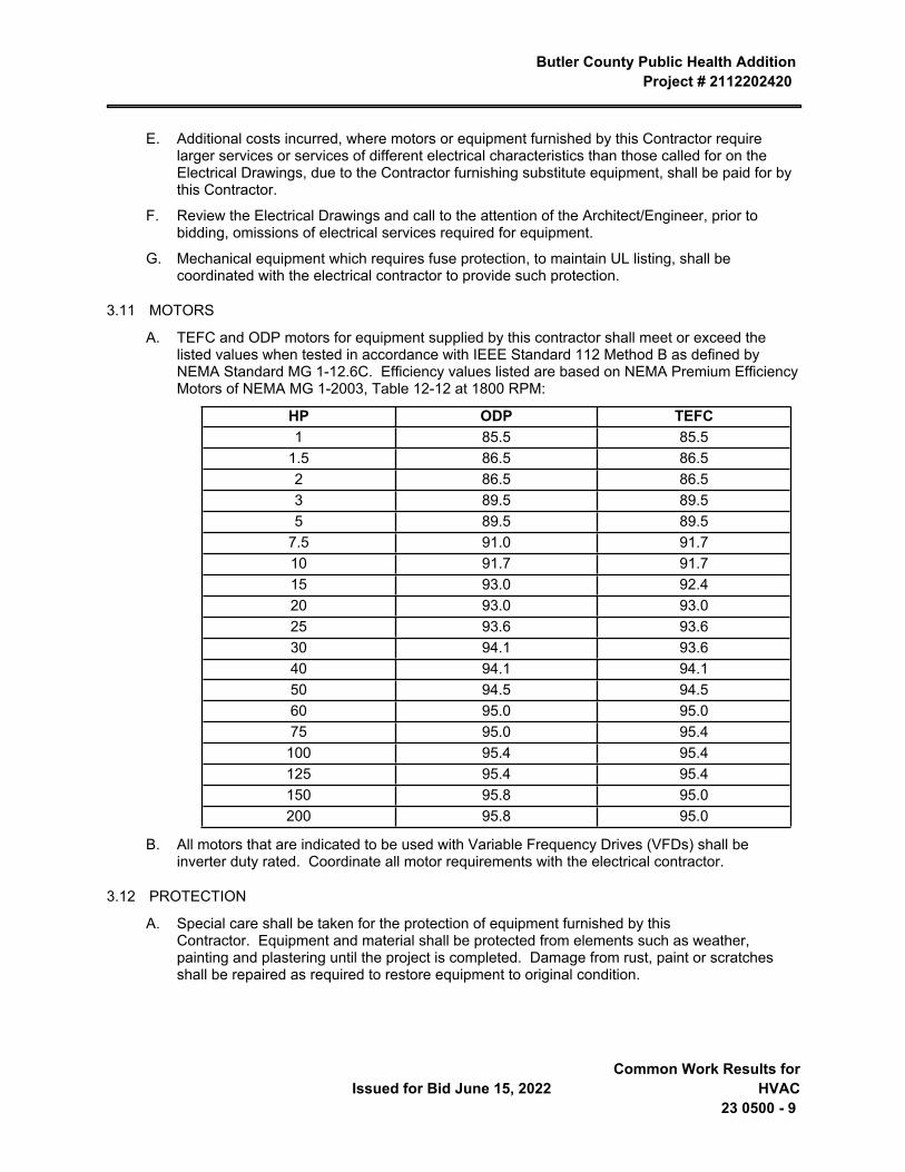
Butler County Public Health Addition Project # 2112202420
Issued for Bid June 15, 2022 Common Work Results for
HVAC23 0500 - 9
E. Additional costs incurred, where motors or equipment furnished by this Contractor require larger services or services of different electrical characteristics than those called for on the Electrical Drawings, due to the Contractor furnishing substitute equipment, shall be paid for by this Contractor.
F. Review the Electrical Drawings and call to the attention of the Architect/Engineer, prior to bidding, omissions of electrical services required for equipment.
G. Mechanical equipment which requires fuse protection, to maintain UL listing, shall be coordinated with the electrical contractor to provide such protection.
3.11 MOTORS
A. TEFC and ODP motors for equipment supplied by this contractor shall meet or exceed the listed values when tested in accordance with IEEE Standard 112 Method B as defined by NEMA Standard MG 1-12.6C. Efficiency values listed are based on NEMA Premium Efficiency Motors of NEMA MG 1-2003, Table 12-12 at 1800 RPM:
HP ODP TEFC1 85.5 85.5
1.5 86.5 86.52 86.5 86.53 89.5 89.55 89.5 89.5
7.5 91.0 91.710 91.7 91.715 93.0 92.420 93.0 93.025 93.6 93.630 94.1 93.640 94.1 94.150 94.5 94.560 95.0 95.075 95.0 95.4
100 95.4 95.4125 95.4 95.4150 95.8 95.0200 95.8 95.0
B. All motors that are indicated to be used with Variable Frequency Drives (VFDs) shall be inverter duty rated. Coordinate all motor requirements with the electrical contractor.
3.12 PROTECTION
A. Special care shall be taken for the protection of equipment furnished by this Contractor. Equipment and material shall be protected from elements such as weather, painting and plastering until the project is completed. Damage from rust, paint or scratches shall be repaired as required to restore equipment to original condition.
Butler County Public Health Addition Project # 2112202420
Common Work Results for HVAC 23 0500 - 10
Issued for Bid June 15, 2022
B. Protection of equipment during the plastering and painting of the building shall be the responsibility of the contractor performing that work, but this shall not relieve this Contractor of the responsibility of checking to assure that adequate protection is being provided.
C. Where the installation or connection of equipment requires this Contractor to work in areas previously finished by other contractors, this Contractor shall be responsible that such areas are protected and are not marred, soiled or otherwise damaged during the course of such work. This Contractor shall arrange with the other contractors for repairing and refinishing of such areas which may be damaged.
D. When heavy materials must be placed upon or transported over the roof deck, sheeting shall be placed to distribute the weight and support such materials. Any damage shall be immediately corrected at no cost to the Owner.
3.13 ASBESTOS IDENTIFICATION AND CONTROL
A. In the event that suspected asbestos containing material (ACM) is encountered during the course of the work, cease operations in the immediate area and promptly notify the Architect/Engineer. Suspected materials will then be sampled and analyzed by the Owner. Should ACM be identified, the Owner's Representative will direct the procedures for abatement, either by subcontract to the Contractor or separate contractor. During abatement operations, cease operations in the immediate area of the abatement. Operations in other areas of the project may be performed, but care must be taken to control dust to avoid contamination of the abatement containment or air monitoring samples. The Contractor shall coordinate activities with the asbestos abatement contractor.
B. Should no ACM be identified, operations may be resumed. Delays caused by identification, analysis or abatement may be added to the time of the contract, at the discretion of the Architect/Engineer by Change Order.
3.14 NOISE AND VIBRATION
A. Be responsible for the installation of all equipment in such a manner as to control the transmission of noise and vibration from any installed equipment or system, so that the sound level does not exceed NC35 in any occupied space. Be responsible for the correction of any objectionable noise in any occupied area due to improperly installed equipment.
3.15 TESTS AND DEMONSTRATIONS
A. Systems shall be tested and placed in proper working order prior to demonstrating systems to the Owner.
B. Prior to acceptance of the mechanical installation, demonstrate to the Owner or his designated representatives essential features and functions of all systems installed, and instruct the Owner in the proper operation and maintenance of such systems.
C. Furnish the necessary trained personnel to perform the demonstrations and instructions, and arrange to have the manufacturer's representatives for the system present to assist with the demonstrations. The Owner and Contractor shall each sign a certification stating that the training has been performed and the Owner accepts same.
3.16 UTILITY REBATE APPLICATIONS
A. This contractor shall be responsible for gathering information necessary for completing local utility rebate applications, and submitting to the proper utility companies for gas and electric rebates. Potential rebates include high efficiency gas boilers, thermostats, timeclocks, motors, and other items furnished by this mechanical contractor.
Butler County Public Health Addition Project # 2112202420
Issued for Bid June 15, 2022 Common Work Results for
HVAC23 0500 - 11
END OF SECTION 23 0500

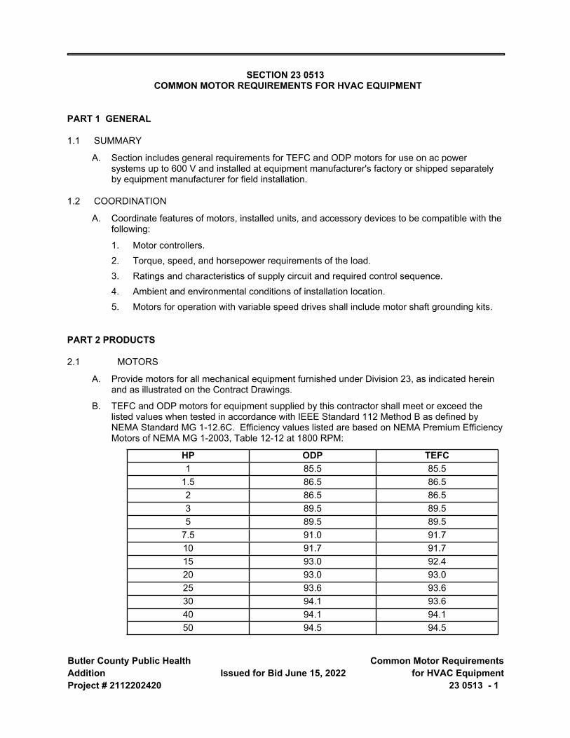
Butler County Public Health AdditionProject # 2112202420
Issued for Bid June 15, 2022 Common Motor Requirements
for HVAC Equipment23 0513 - 1
SECTION 23 0513 COMMON MOTOR REQUIREMENTS FOR HVAC EQUIPMENT
PART 1 GENERAL
1.1 SUMMARY
A. Section includes general requirements for TEFC and ODP motors for use on ac power systems up to 600 V and installed at equipment manufacturer's factory or shipped separately by equipment manufacturer for field installation.
1.2 COORDINATION
A. Coordinate features of motors, installed units, and accessory devices to be compatible with the following:
1. Motor controllers.2. Torque, speed, and horsepower requirements of the load.3. Ratings and characteristics of supply circuit and required control sequence.4. Ambient and environmental conditions of installation location.5. Motors for operation with variable speed drives shall include motor shaft grounding kits.
PART 2 PRODUCTS
2.1 MOTORS
A. Provide motors for all mechanical equipment furnished under Division 23, as indicated herein and as illustrated on the Contract Drawings.
B. TEFC and ODP motors for equipment supplied by this contractor shall meet or exceed the listed values when tested in accordance with IEEE Standard 112 Method B as defined by NEMA Standard MG 1-12.6C. Efficiency values listed are based on NEMA Premium Efficiency Motors of NEMA MG 1-2003, Table 12-12 at 1800 RPM:
HP ODP TEFC1 85.5 85.5
1.5 86.5 86.52 86.5 86.53 89.5 89.55 89.5 89.5
7.5 91.0 91.710 91.7 91.715 93.0 92.420 93.0 93.025 93.6 93.630 94.1 93.640 94.1 94.150 94.5 94.5
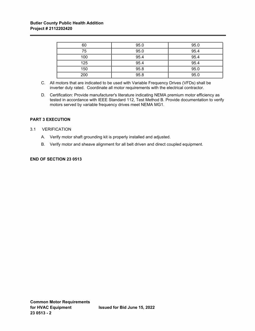
Butler County Public Health Addition Project # 2112202420
Common Motor Requirements for HVAC Equipment 23 0513 - 2
Issued for Bid June 15, 2022
60 95.0 95.075 95.0 95.4
100 95.4 95.4125 95.4 95.4150 95.8 95.0200 95.8 95.0
C. All motors that are indicated to be used with Variable Frequency Drives (VFDs) shall be inverter duty rated. Coordinate all motor requirements with the electrical contractor.
D. Certification: Provide manufacturer's literature indicating NEMA premium motor efficiency as tested in accordance with IEEE Standard 112, Test Method B. Provide documentation to verify motors served by variable frequency drives meet NEMA MG1.
PART 3 EXECUTION
3.1 VERIFICATION
A. Verify motor shaft grounding kit is properly installed and adjusted.
B. Verify motor and sheave alignment for all belt driven and direct coupled equipment.
END OF SECTION 23 0513
Butler County Public Health AdditionProject # 2112202420
Issued for Bid June 15, 2022 Expansion Fittings and Loops
for HVAC Piping23 0516 - 1
SECTION 23 0516 EXPANSION FITTINGS AND LOOPS FOR HVAC PIPING
PART 1 GENERAL
1.1 SECTION INCLUDES
A. Flexible pipe connectors.
B. Expansion joints and compensators.
1.2 RELATED REQUIREMENTS
A. Section 23 2213 - Steam and Condensate Heating Piping.
1.3 REFERENCE STANDARDS
A. UL (DIR) - Online Certifications Directory Current Edition.
1.4 SUBMITTALS
A. See Section 01 3000 - Administrative Requirements for submittal procedures.
B. Product Data:
1. Flexible Pipe Connectors: Indicate maximum temperature and pressure rating, face-to-face length, live length, hose wall thickness, hose convolutions per foot (meter) and per assembly, fundamental frequency of assembly, braid structure, and total number of wires in braid.
2. Expansion Joints: Indicate maximum temperature and pressure rating, and maximum expansion compensation.
C. Submit shop drawings showing piping systems with all anchors, guides and expansion compensators identified. Indicate amount of expansion at each loop or joint. Submit calculations.
D. Design Data: Indicate selection calculations.
PART 2 PRODUCTS
2.1 REGULATORY REQUIREMENTS
A. Comply with UL (DIR) requirements.
2.2 FLEXIBLE PIPE CONNECTORS - STEEL PIPING
A. Manufacturers:
1. Mercer Rubber Company2. The Metraflex Company3. Substitutions: See Section 01 6000 - Product Requirements.
B. Inner Hose: Bronze.
C. Exterior Sleeve: Single braided, stainless steel.
Butler County Public Health Addition Project # 2112202420
Expansion Fittings and Loops for HVAC Piping 23 0516 - 2
Issued for Bid June 15, 2022
D. Pressure Rating: 125 psi up to 12 inch (862 kPa up to 300 mm, DN).
E. End Connections: Flanged.
F. Size: Use pipe sized units.
G. Maximum offset: 3/4 inch (20 mm) on each side of installed center line.
2.3 EXPANSION JOINTS - METAL BELLOWS TYPE
2.4 ACCESSORIES
A. Pipe Alignment Guides:
B. Engineered Riser Anchor Clamps:
C. Swivel Joints:
2.5 PUMP CONNECTORS
A. Bellows type:
1. Laminated, multi-ply of 304 stainless steel2. Extend and attach to flanges by van stoning for a continuous stainless steel surface3. Carbon steel 150-lb flanges4. 150-lb working pressure5. Keflex 150 TR series
B. Furnished with carbon steel tie rods to prevent extension and spacers to limit compression
PART 3 EXECUTION
3.1 INSTALLATION
A. Install in accordance with manufacturer's instructions.
3.2 EXPANSION
3.3 JOINTS
3.4 LOOPS
3.5 ANCHORS
A. Install anchors at proper locations to prevent stresses from exceeding those permitted by ANSI B31, and to prevent transfer of loading and stresses to connected equipment.
B. Fabricate and install anchor by welding steel shapes, plates and bars to piping and to structure. Comply with ANSI B31 and with AWS standards.
C. Structural members for anchoring shall be firmly embedded or fastened into building members and shall withstand force of pipe expansion without straining building structure.
D. Where expansion joints, compensators or loops are indicated, install anchors in accordance with expansion unit manufacturer's written instructions, to limit movement of piping and forces to maximums recommended by manufacturer for each unit.
Butler County Public Health Addition Project # 2112202420
Issued for Bid June 15, 2022 Expansion Fittings and Loops
for HVAC Piping23 0516 - 3
E. Anchor Spacings: Where not otherwise indicated, install anchors at ends of principal pipe-runs, at intermediate points in pipe runs between expansion loops and bends. Make provisions for preset anchors as required to accommodate both expansion and contraction of piping.
F. Provide copper anchors for copper piping systems.
3.6 GUIDES
END OF SECTION


Butler County Public Health AdditionProject # 2112202420
Issued for Bid June 15, 2022 Sleeves and Sleeve Seals for
HVAC Piping23 0517 - 1
SECTION 23 0517 SLEEVES AND SLEEVE SEALS FOR HVAC PIPING
PART 2 PRODUCTS
1.1 PIPE SLEEVES
A. Manufacturers:
1. Flexicraft Industries; Pipe Wall Sleeve: www.flexicraft.com/#sle.B. Vertical Piping:
1. Sleeve Length: 1 inch (25 mm) above finished floor.2. Provide sealant for watertight joint.
C. Clearances:
1. Provide allowance for insulated piping.2. All Rated Openings: Caulked tight with fire stopping material in compliance with ASTM
E814 in accordance with Section 07 8400 to prevent the spread of fire, smoke, and gases.
1.2 MANUFACTURED SLEEVE-SEAL SYSTEMS
A. Manufacturers:
1. Advance Products & Systems, LLC; Innerlynx: www.apsonline.com/#sle.2. Flexicraft Industries; PipeSeal: www.flexicraft.com/#sle.
PART 3 EXECUTION
2.1 PREPARATION
A. Ream pipe and tube ends. Remove burrs. Bevel plain end ferrous pipe.
B. Remove scale and foreign material, from inside and outside, before assembly.
2.2 INSTALLATION
A. Route piping in orderly manner, plumb and parallel to building structure. Maintain gradient.
B. Install piping to conserve building space, to not interfere with use of space and other work.
C. Install piping and pipe sleeves to allow for expansion and contraction without stressing pipe, joints, or connected equipment.
D. Inserts:
1. Provide inserts for placement in concrete formwork.E. Provide sleeves when penetrating footings, floors, walls, partitions, and [_______]. Seal pipe
including sleeve penetrations to achieve fire resistance equivalent to fire separation required.
1. Underground Piping: Caulk pipe sleeve watertight with lead and oakum or mechanically expandable chloroprene inserts with bitumen sealed metal components.
2. Aboveground Piping:

Butler County Public Health Addition Project # 2112202420
Sleeves and Sleeve Seals for HVAC Piping 23 0517 - 2
Issued for Bid June 15, 2022
a. Pack solid using mineral fiber in compliance with ASTM C592.
b. Fill space with an elastomer caulk to a depth of 0.50 inch (15 mm) where penetrations occur between conditioned and unconditioned spaces.
3. Caulk exterior wall sleeves watertight with lead and oakum or mechanically expandable chloroprene inserts with mastic-sealed components.
F. When installing more than one piping system material, ensure system components are compatible and joined to ensure the integrity of the system. Provide necessary joining fittings. Ensure flanges, union, and couplings for servicing are consistently provided.
2.3 CLEANING
A. Upon completion of work, clean all parts of the installation.
B. Clean equipment, pipes, valves, and fittings of grease, metal cuttings, and sludge that may have accumulated from the installation and testing of the system.
C. See Section 01 7419 - Construction Waste Management and Disposal, for additional requirements.
END OF SECTION
Butler County Public Health AdditionProject # 2112202420
Issued for Bid June 15, 2022 Meters and Gauges for HVAC
Piping23 0519 - 1
SECTION 23 0519 METERS AND GAUGES FOR HVAC PIPING
PART 1 GENERAL
1.1 SECTION INCLUDES
A. Flow meters.
B. Pressure gauges and pressure gauge taps.
C. Thermometers and thermometer wells.
D. Static pressure gauges.
1.2 RELATED REQUIREMENTS
A. Section 23 0923 - Direct-Digital Control System for HVAC.
B. Section 23 2113 - Hydronic Piping.
1.3 REFERENCE STANDARDS
A. ASME B40.100 - Pressure Gauges and Gauge Attachments 2013.
B. ASME MFC-3M - Measurement of Fluid Flow in Pipes Using Orifice, Nozzle, and Venturi 2004 (Reaffirmed 2017).
C. ASTM E1 - Standard Specification for ASTM Liquid-in-Glass Thermometers 2014 (Reapproved 2020).
D. ASTM E77 - Standard Test Method for Inspection and Verification of Thermometers 2014 (Reapproved 2021).
E. AWWA M6 - Water Meters -- Selection, Installation, Testing, and Maintenance 2012, with Addendum (2018).
F. UL 393 - Indicating Pressure Gauges for Fire-Protection Service Current Edition, Including All Revisions.
1.4 SUBMITTALS
A. See Section 01 3000 - Administrative Requirements, for submittal procedures.
B. Product Data: Provide list that indicates use, operating range, total range and location for manufactured components.
C. Project Record Documents: Record actual locations of components and instrumentation.
D. Maintenance Materials: Furnish the following for Owner's use in maintenance of project.
1. See Section 01 6000 - Product Requirements, for additional provisions.
1.5 FIELD CONDITIONS
A. Do not install instrumentation when areas are under construction, except for required rough-in, taps, supports and test plugs.
PART 2 PRODUCTS
Butler County Public Health Addition Project # 2112202420
Meters and Gauges for HVAC Piping 23 0519 - 2
Issued for Bid June 15, 2022
2.1 LIQUID FLOW METERS
A. Manufacturers:
1. Dwyer Instruments, Inc2. McCrometer3. Venture Measurement, a Danaher Company4. Veris Industries
B. Calibrated ASME MFC-3M Venturi orifice plate and flanges with valved taps, chart for conversion of differential pressure readings to flow rate, with pressure gauge in case.
C. Annular element flow stations with meter set.
1. Measuring Station: Type 316 stainless steel pitot type flow element inserted through welded threaded couplet, with safety shut-off valves and quick coupling connections, and permanent metal tag indicating design flow rate, reading for design flow rate, metered fluid, line size, station or location number.
a. Pressure rating: 275 psi (1896 kPa).
b. Maximum temperature: 400 degrees F (204 degrees C).
c. Accuracy: Plus 0.55 percent to minus 2.30 percent.
2. Portable Meter Set: Dry single diaphragm type pressure gauge with 6 inch (150 mm) dial pointer, stainless steel wetted metal parts, variable pulsation damper, equalizing valve, two bleed valves, and master chart for direct conversion of meter readings to flow rate, mounted in rust-proof carrying case with two ten foot (3 m) long rubber test hoses with brass valves or quick connections for measuring stations.
2.2 PRESSURE GAUGES
A. Manufacturers:
1. Dwyer Instruments, Inc2. Moeller Instrument Company, Inc3. Weiss, Weksler, Ashcroft, McDaniley, U.S. Gauge or Therice4. Substitutions: See Section 01 6000 - Product Requirements.
B. Pressure Gauges: ASME B40.100, UL 393 drawn steel case, phosphor bronze bourdon tube, rotary brass movement, brass socket, with front recalibration adjustment, black scale on white background.
2.3 PRESSURE GAUGE TAPPINGS
A. Gauge Cock: Tee or lever handle, brass for maximum 150 psi (1034 kPa).
B. Needle Valve: Brass, 1/4 inch (6 mm) NPT for minimum 150 psi (1034 kPa).
C. Pulsation Damper: Pressure snubber, brass with 1/4 inch (6 mm) connections.
D. Syphon: Steel, Schedule 40, 1/4 inch (6 mm) angle or straight pattern.
2.4 STEM TYPE THERMOMETERS
A. Manufacturers:
Butler County Public Health Addition Project # 2112202420
Issued for Bid June 15, 2022 Meters and Gauges for HVAC
Piping23 0519 - 3
1. Dwyer Instruments, Inc2. Omega Engineering, Inc3. Weksler Glass Thermometer Corp
B. Thermometers
1. Provide wells constructed of brass or stainless steel, pressure rated to match piping system design, 2" extension for insulated piping and cap nut with chain fastened permanently to thermometer well.
2. Fixed Mounting: Red- or blue-appearing non-toxic liquid in glass; ASTM E1; lens front tube, cast aluminum case with enamel finish.
a. Size: 9 inch (225 mm) scale.
b. Window: Clear Lexan.
c. Accuracy: 2 percent, per ASTM E77.
d. Calibration: Degrees F.
3. Adjustable Angle: Red- or blue-appearing non-toxic liquid in glass; ASTM E1; lens front tube, cast aluminum case with enamel finish, cast aluminum adjustable joint with positive locking device; adjustable 360 degrees in horizontal plane, 180 degrees in vertical plane.
a. Size: 9 inch (225 mm) scale.
b. Window: Clear Lexan.
c. Stem: 3/4 inch (20 mm) NPT brass.
d. Accuracy: 2 percent, per ASTM E77.
e. Calibration: Degrees F.
2.5 DIAL THERMOMETERS
A. Manufacturers:
1. Dwyer Instruments, Inc2. Omega Engineering, Inc3. Weksler Glass Thermometer Corp4. Weiss, Weksler, Ashcroft, Reotemp, U.S. Gauge or Therice.
B. Thermometers
1. Fixed Mounting: Dial type bimetallic actuated; ASTM E1; stainless steel case, silicone fluid damping, white with black markings and black pointer, hermetically sealed lens, stainless steel stem.
a. Size: 5 inch (125 mm) diameter dial.
b. Lens: Clear glass.
c. Accuracy: 1 percent.
d. Calibration: Degrees F.
2.6 THERMOMETER SUPPORTS
Butler County Public Health Addition Project # 2112202420
Meters and Gauges for HVAC Piping 23 0519 - 4
Issued for Bid June 15, 2022
A. Socket: Brass separable sockets for thermometer stems with or without extensions as required, and with cap and chain.
B. Flange: 3 inch (75 mm) outside diameter reversible flange, designed to fasten to sheet metal air ducts, with brass perforated stem.
2.7 TEST PLUGS
A. Test Plug: 1/4 inch (6 mm) or 1/2 inch (13 mm) brass fitting and cap for receiving 1/8 inch (3 mm) outside diameter pressure or temperature probe with neoprene core for temperatures up to 200 degrees F (93 degrees C).
B. Test Kit: Carrying case, internally padded and fitted containing one 2-1/2 inch (60 mm) diameter pressure gauges, one gauge adapters with 1/8 inch (3 mm) probes, two 1 inch (25 mm) dial thermometers.
2.8 STATIC PRESSURE GAUGES
A. Manufacturers:
1. Dwyer Instruments, Inc2. Omega Engineering, Inc3. Veris Industries4. Weksler Glass Thermometer Corp
B. 3-1/2 inch (90 mm) diameter dial in metal case, diaphragm actuated, black figures on white background, front recalibration adjustment, 2 percent of full scale accuracy.
C. Accessories: Static pressure tips with compression fittings for bulkhead mounting, 1/4 inch (6 mm) diameter tubing.
PART 3 EXECUTION
3.1 INSTALLATION
A. Install in accordance with manufacturer's instructions.
B. Install positive displacement meters with isolating valves on inlet and outlet to AWWA M6. Provide full line size valved bypass with globe valve for liquid service meters.
C. Provide one pressure gauge per pump, installing taps before strainers and on suction and discharge of pump. Pipe to gauge.
D. Install pressure gauges with pulsation dampers. Provide gauge cock to isolate each gauge. Provide siphon on gauges in steam systems. Extend nipples and siphons to allow clearance from insulation.
E. Install thermometers in piping systems in sockets in short couplings. Enlarge pipes smaller than 2-1/2 inch (60 mm) for installation of thermometer sockets. Ensure sockets allow clearance from insulation.
F. Install thermometers in air duct systems on flanges.
G. Install thermometer sockets adjacent to controls system thermostat, transmitter, or sensor sockets. Refer to Section 23 0943. Where thermometers are provided on local panels, duct or pipe mounted thermometers are not required.
Butler County Public Health Addition Project # 2112202420
Issued for Bid June 15, 2022 Meters and Gauges for HVAC
Piping23 0519 - 5
H. Locate duct mounted thermometers minimum 10 feet (3 m) downstream of mixing dampers, coils, or other devices causing air turbulence.
I. Coil and conceal excess capillary on remote element instruments.
J. Provide instruments with scale ranges selected according to service with largest appropriate scale.
K. Install gauges and thermometers in locations where they are easily read from normal operating level. Install vertical to 45 degrees off vertical.
L. Adjust gauges and thermometers to final angle, clean windows and lenses, and calibrate to zero.
M. Locate test plugs adjacent thermometers and thermometer sockets.
N. Install thermometers in discharge and return piping at boilers, convertors, heat exchangers and chillers, at each large heating and cooling coils and at other points as shown on drawings.
O. Install gauge for each pump, mounted on 1/4 in. galvanized steel pipe manifold connected to the suction and discharge of the pump, with lever handle union cocks in the manifold on each side of the gauge, so that the gauge may be opened to either the suction or discharge pressure.
P. Install gauges with snubbers and turn cocks on the suction and discharge lines of each pump.
Q. install gauges on chiller, boiler, and convertor headers, at pressure reducing valves and at other points as shown on drawings.
3.2 SCHEDULE
A. Flow Meters, Location:
1. Heating water system.B. Pressure Gauges, Location and Scale Range:
1. Pumps, 0 to 40 psi (0 to [____] kPa).2. Backflow preventers, 0 to 100 psi (0 to [____] kPa)
C. Pressure Gauge Tappings, Location:
1. Control valves 3/4 inch (20 mm) & larger - inlets and outlets.2. Major coils - inlets and outlets.3. Boiler - inlets and outlets.
D. Stem Type Thermometers, Location and Scale Range:
1. Boilers - inlets and outlets, 0 to 200 degrees F (0 to [____] Degrees C).2. Domestic hot water supply and recirculation, 0 to 140 degrees F (0 to [____] Degrees C).
E. Dial Thermometers, Location and Scale Range:
1. Each supply air zone, 0 to 120 degrees F (0 to [____] Degrees C).2. Outside air, 0 to 120 degrees F (0 to [____] Degrees C).3. Return air, 0 to 120 degrees F (0 to [____] Degrees C).
F. Static Pressure and Filter Gauges, Location and Scale Range:
1. Supply fan discharge, 0 to 1 inches W.C. (0 to [____] Pa).

Butler County Public Health Addition Project # 2112202420
Meters and Gauges for HVAC Piping 23 0519 - 6
Issued for Bid June 15, 2022
END OF SECTION
Butler County Public Health AdditionProject # 2112202420
Issued for Bid June 15, 2022 General-Duty Valves for HVAC
Piping23 0523 - 1
SECTION 23 0523 GENERAL-DUTY VALVES FOR HVAC PIPING
PART 1 GENERAL
1.1 SECTION INCLUDES
A. Angle valves.
B. Globe valves.
C. Ball valves.
D. Butterfly valves.
E. Check valves.
F. Gate valves.
G. Chainwheels.
1.2 RELATED REQUIREMENTS
A. Section 08 3100 - Access Doors and Panels.
B. Section 23 0548 - Vibration and Seismic Controls for HVAC.
C. Section 23 0553 - Identification for HVAC Piping and Equipment.
D. Section 23 0716 - HVAC Equipment Insulation.
E. Section 23 0719 - HVAC Piping Insulation.
F. Section 23 2113 - Hydronic Piping.
1.3 ABBREVIATIONS AND ACRONYMS
A. CWP: Cold working pressure.
B. EPDM: Ethylene propylene copolymer rubber.
C. NBR: Acrylonitrile-butadiene, Buna-N, or nitrile rubber.
D. NRS: Nonrising stem.
E. OS&Y: Outside screw and yoke.
F. PTFE: Polytetrafluoroethylene.
G. RS: Rising stem.
H. TFE: Tetrafluoroethylene.
I. WOG: Water, oil, and gas.
1.4 REFERENCE STANDARDS
A. ASME B1.20.1 - Pipe Threads, General Purpose, Inch 2013 (Reaffirmed 2018).
B. ASME B16.1 - Gray Iron Pipe Flanges and Flanged Fittings: Classes 25, 125, and 250 2020.
C. ASME B16.5 - Pipe Flanges and Flanged Fittings: NPS 1/2 through NPS 24 Metric/Inch Standard 2020.
Butler County Public Health Addition Project # 2112202420
General-Duty Valves for HVAC Piping 23 0523 - 2
Issued for Bid June 15, 2022
D. ASME B16.10 - Face-to-Face and End-to-End Dimensions of Valves 2017.
E. ASME B16.18 - Cast Copper Alloy Solder Joint Pressure Fittings 2021.
F. ASME B16.34 - Valves — Flanged, Threaded, and Welding End 2020.
G. ASME B31.1 - Power Piping 2020.
H. ASME B31.9 - Building Services Piping 2020.
I. ASME BPVC-IX - Boiler and Pressure Vessel Code, Section IX - Qualification Standard for Welding, Brazing, and Fusing Procedures; Welders; Brazers; and Welding, Brazing, and Fusing Operators 2021.
J. ASTM A126 - Standard Specification for Gray Iron Castings for Valves, Flanges, and Pipe Fittings 2004 (Reapproved 2019).
K. ASTM A216/A216M - Standard Specification for Steel Castings, Carbon, Suitable for Fusion Welding, for High-Temperature Service 2021.
L. ASTM A536 - Standard Specification for Ductile Iron Castings 1984, with Editorial Revision (2019).
M. ASTM B62 - Standard Specification for Composition Bronze or Ounce Metal Castings 2017.
N. AWWA C606 - Grooved and Shouldered Joints 2015.
O. MSS SP-45 - Drain and Bypass Connections 2020.
P. MSS SP-67 - Butterfly Valves 2017, with Errata.
Q. MSS SP-70 - Gray Iron Gate Valves, Flanged and Threaded Ends 2011.
R. MSS SP-72 - Ball Valves with Flanged or Butt-Welding Ends for General Service 2010a.
S. MSS SP-80 - Bronze Gate, Globe, Angle, and Check Valves 2019.
T. MSS SP-110 - Ball Valves Threaded, Socket-Welding, Solder Joint, Grooved and Flared Ends 2010, with Errata .
1.5 SUBMITTALS
A. See Section 01 3000 - Administrative Requirements for submittal procedures.
B. Product Data: Provide data on valves including manufacturers catalog information. Submit performance ratings, rough-in details, weights, support requirements, and piping connections.
C. Submit valve schedule, indicating valve ID, type, size and intended service and location.
D. Warranty: Submit manufacturer warranty and ensure that forms have been completed in Owner's name and registered with manufacturer.
E. Maintenance Materials: Furnish Owner with one wrench for every five plug valves, in each size of square plug valve head.
1. See Section 01 6000 - Product Requirements for additional provisions.
1.6 QUALITY ASSURANCE
A. Manufacturer:
1. Obtain valves for each valve type from single manufacturer.2. Company must specialize in manufacturing products specified in this section, with not less
than three years of documented experience.
Butler County Public Health Addition Project # 2112202420
Issued for Bid June 15, 2022 General-Duty Valves for HVAC
Piping23 0523 - 3
B. Welding Materials and Procedures: Comply with ASME BPVC-IX.
1.7 MANUFACTURERS
A. Subject to compliance with requirements, provide products manufactured by one of the following, as listed for each valve type, or Engineer-approved equivalent.
1. Valve type approved Manufacturer2. Gate, Globe and Check Valves: Crane, Stockham, Lunkenheimer, Hammond, Industrial
Series, NIBCO, Milwaukee3. Characterized Colntrol Valve: Belimo, Apollo, Watts4. Ball Valves: Jamesbury, Apollo, Jenkins, Milwaukee, Watts, Powell, or NIBCO5. Buterfly Valves: Keystone, Demco, Milwaukee, Centerline, NIBCO6. High Performance Butterfly Valve: Jamesbury, Durco, Adams7. Plug Valves: Nordstrom, Stockham, W-K-M8. Refrigerant Piping Valves: Packless, Kerotest, Henry Pratt, Superior, Parker9. Automatic Valves: ASCO, Clayton, Parker10. PVC and CPVC Valves: ASAHI/America, Watts, or NIBCO
1.8 DELIVERY, STORAGE, AND HANDLING
A. Prepare valves for shipping as follows:
1. Minimize exposure of operable surfaces by setting plug and ball valves to open position.2. Protect valve parts exposed to piped medium against rust and corrosion.3. Protect valve piping connections such as grooves, weld ends, threads, and flange faces.4. Adjust globe, gate, and angle valves to the closed position to avoid clattering.5. Secure check valves in either the closed position or open position.6. Adjust butterfly valves to closed or partially closed position.
B. Use the following precautions during storage:
1. Maintain valve end protection and protect flanges and specialties from dirt.
a. Provide temporary inlet and outlet caps.
2. Store valves in shipping containers and maintain in place until installation.
a. Store valves indoors in dry environment.
b. Store valves off the ground in watertight enclosures when indoor storage is not an option.
C. Exercise the following precautions for handling:
1. Handle large valves with sling, modified to avoid damage to exposed parts.2. Avoid the use of operating handles or stems as rigging or lifting points.
PART 2 PRODUCTS
Butler County Public Health Addition Project # 2112202420
General-Duty Valves for HVAC Piping 23 0523 - 4
Issued for Bid June 15, 2022
2.1 APPLICATIONS
A. See drawings for specific valve locations.
B. Listed pipe sizes shown using nominal pipe sizes (NPS) and nominal diameter (DN).
C. Substitutions of valves with higher CWP classes or WSP ratings for same valve types are permitted when specified CWP ratings or WSP classes are not available.
D. Required Valve End Connections for Non-Wafer Types:
1. Steel Pipe:
a. Size 2 inch (50 mm, DN) and Smaller: Threaded ends.
b. Size 2-1/2 inch (65 mm, DN) and Larger: Grooved ends.
2. Copper Tube:
a. Size 2 inch (50 mm, DN) and Smaller: Threaded ends, except solder-joint valve-ends.
b. Size 2-1/2 inch (65 mm, DN) and Larger: Grooved ends.
E. Heating Hot Water Valves:
1. 2 NPS (50 DN) and Smaller, Brass and Bronze Valves:
a. Threaded ends.
b. Angle: Bronze disc, Class 125.
c. Ball: Full port, one piece, brass trim.
d. Swing Check: Bronze disc, Class 125.
e. Gate: NRS, Class 125.
f. Globe: Bronze disc, Class 125.
2.2 GENERAL REQUIREMENTS
A. Valve Pressure and Temperature Ratings: No less than rating indicated; as required for system pressures and temperatures. If no temperature or pressure rating is given for each system, Contractor shall verify valve ratings with Design Professional prior to installing.
B. Valve Sizes: Match upstream piping unless otherwise indicated.
C. Valve Actuator Types:
1. Gear Actuator: Quarter-turn valves 8 inch (200 mm, DN) and larger.2. Handwheel: Valves other than quarter-turn types.3. Hand Lever: Quarter-turn valves 6 NPS (150 DN) and smaller.4. Wrench: Plug valves with square heads.5. Chainwheel: Device for attachment to valve handwheel, stem, or other actuator, of size
and with chain for mounting height, as indicated in the "Valve Installation" Article.D. Valves in Insulated Piping: Provide 2 inch (50 mm, DN) stem extensions and the following
features:
1. Gate Valves: Rising stem.
Butler County Public Health Addition Project # 2112202420
Issued for Bid June 15, 2022 General-Duty Valves for HVAC
Piping23 0523 - 5
2. Ball Valves: Extended operating handle of non-thermal-conductive material, and protective sleeve that allows operation of valve without breaking the vapor seal or disturbing insulation.
3. Butterfly Valves: Extended neck.4. Memory Stops: Fully adjustable after insulation is installed.
E. Valve-End Connections:
1. Threaded End Valves: ASME B1.20.1.2. Flanges on Iron Valves: ASME B16.1 for flanges on iron valves.3. Pipe Flanges and Flanged Fittings 1/2 inch (15 mm, DN) through 24 inch (600 mm,
DN): ASME B16.5.4. Solder Joint Connections: ASME B16.18.5. Grooved End Connections: AWWA C606.
F. General ASME Compliance:
1. Ferrous Valve Dimensions and Design Criteria: ASME B16.10 and ASME B16.34.2. Power Piping Valves: ASME B31.1.3. Building Services Piping Valves: ASME B31.9.
G. Bronze Valves:
1. Fabricate from dezincification resistant material.2. Copper alloys containing more than 15 percent zinc are not permitted.
H. Valve Bypass and Drain Connections: MSS SP-45.
I. Source Limitations: Obtain each valve type from a single manufacturer.
2.3 BRONZE, ANGLE VALVES
A. CWP Rating: Class 125: 200 psi (1,380 kPa) and Class 150: 300 psi (2,070 kPa):
1. Comply with MSS SP-80, Type 1.2. Body: Bronze; ASTM B62, with integral seat and screw in bonnet.3. Ends: Threaded.4. Stem: Bronze.5. Disc: Bronze, PTFE, or TFE.6. Packing: Asbestos free.7. Handwheel: Bronze or aluminum.
2.4 BRONZE, GLOBE VALVES
A. CWP Rating: Class 125: 200 psi (1,380 kPa):
1. Comply with MSS SP-80, Type 1.2. Body: Bronze; ASTM B62, with integral seat and screw in bonnet.3. Ends: Threaded or solder joint.4. Stem and Disc: Bronze or PTFE.5. Packing: Asbestos free.
Butler County Public Health Addition Project # 2112202420
General-Duty Valves for HVAC Piping 23 0523 - 6
Issued for Bid June 15, 2022
a. Handwheel: Malleable iron.
2.5 BRASS, BALL VALVES
A. One Piece, Full Port with Brass Trim and Push-to-fit or Threaded Connections:
1. Comply with MSS SP-110.2. CWP Rating: 200 psi (1,379 kPa).3. Body: Forged brass.4. Ends: Threaded.5. Seats: PTFE or TFE.6. Stem: Brass.7. Ball: Chrome-plated brass.8. Operator: Handle.9. Manufacturers:
a. Ferguson Enterprises Inc; [_____]
B. Two Piece, Full Port with Stainless Steel Trim and Threaded Connections:
1. Comply with MSS SP-110.2. SWP Rating: 150 psi (1,035 kPa).3. CWP Rating: 600 psig (4140 kPa), WOG.4. Vacuum Rating: 28.9 in-Hg (97.9 kPa).5. Body: Forged brass.6. Seats: PTFE.7. Stem: Stainless Steel.8. Ball: Chrome-plated brass.9. Cap: Include cap-gasket and chain for 3/4 inch (20 mm, DN) hose connection.10. Operator: Lockable handle and memory stop.11. Manufacturers:
a. Apollo Valves; [______]
b. Ferguson Enterprises Inc
c. Jomar Valves, a division of Jomar Group; [_____]: www.jomarvalve.com/#sle.
C. Two Piece, Full Port with Press Connection:
1. WOG Rating: 250 psi (1,724 kPa).2. Body: Forged brass.3. Seats: EPDM.4. Ball: Chrome-plated brass.5. Blow-out Proof Stem: Forged brass.6. Operator: Provide lockable handle.
Butler County Public Health Addition Project # 2112202420
Issued for Bid June 15, 2022 General-Duty Valves for HVAC
Piping23 0523 - 7
7. Maximum Service Temperature: 250 degrees F (121.1 degrees C).8. Manufacturers:
a. FNW; 430: www.fnw.com/#sle.
b. Jomar Valves, a division of Jomar Group; [_____]: www.jomarvalve.com/#sle.
2.6 BRONZE, BALL VALVES
A. General:
1. Fabricate from dezincification resistant material.2. Copper alloys containing more than 15 percent zinc are not permitted.
B. One Piece, Reduced Port with Bronze Trim:
1. Comply with MSS SP-110.2. CWP Rating: 400 psi (2,758 kPa).3. Ends: Threaded.4. Seats: PTFE.5. Stem: Bronze.6. Ball: Chrome plated brass.7. Manufacturers:
a. Viega LLC
C. Two Piece, Full Port with Bronze or Brass Trim:
1. Comply with MSS SP-110.2. WSP Rating: 150 psi (1,035 kPa).3. WOG Rating: 400 psi (2,758 kPa).4. Body: Forged bronze or dezincified-brass alloy.5. Ends: Threaded.6. Seats: PTFE.7. Stem: Bronze or brass.8. Ball: Chrome plated brass.9. Operator: Provide lockable handle and stem extension.10. Manufacturers:
a. Apollo Valves
b. FNW; X450: www.fnw.com/#sle.
c. Jomar Valves, a division of Jomar Group; [_____]: www.jomarvalve.com/#sle.
d. Viega LLC
2.7 IRON, SINGLE FLANGE BUTTERFLY VALVES
A. Lug Style: Bi-directional dead-end service without use of downstream flange.
1. Size: As indicated on drawings, Class 125.
Butler County Public Health Addition Project # 2112202420
General-Duty Valves for HVAC Piping 23 0523 - 8
Issued for Bid June 15, 2022
2. Comply with MSS SP-67, Type I.3. Body Material: ASTM A126 cast iron or ASTM A536 ductile iron.4. Stem: One or two-piece stainless steel.5. Seat: NBR.6. Disc: Coated ductile iron.7. Removable Manual Actuator: Lockable handle or worm-gear-connected handwheel with
open/close position indication.8. Service Temperature Range: Minus 30 to 250 degrees F (Minus 34.4 to 121.1 degrees C).9. Operator: Gear operator with handwheel over direct-mount actuator base.10. Manufacturers:
a. Apollo Valves; [______]: www.apollovalves.com/#sle.
b. FNW; 711: www.fnw.com/#sle.
c. Jomar Valves, a division of Jomar Group; [_____]: www.jomarvalve.com/#sle.
d. Nexus Valve, Inc; [_____]: www.nexusvalve.com/#sle.
2.8 BRASS, INLINE CHECK VALVES
A. Class 150: CWP Rating: 200 psi (1,380 kPa) .
B. Maximum Service Temperature: 250 degreess F (121.1 degreess C).
C. Body: Forged brass.
D. Disc: Forged brass.
E. Seal: PTFE, bubble tight.
F. End-Connections: Press.
G. Manufacturers:
1. Jomar Valves, a division of Jomar Group; [_____]: www.jomarvalve.com/#sle.2. FNW; X431: www.fnw.com/#sle.
2.9 BRASS, HORIZONTAL SWING CHECK VALVES
A. Threaded End-Connections:
1. Class 125: CWP Rating: 200 psi (1,380 kPa).2. Body: Forged brass.3. Disc: Forged brass.4. Hinge-Pin, Screw, and Cap: Forged brass.5. Manufacturers:
a. Jomar Valves, a division of Jomar Group; [_____]: www.jomarvalve.com/#sle.
B. Press End-Connections:
1. Class 125: WOG Rating: 200 psi (1,380 kPa).
Butler County Public Health Addition Project # 2112202420
Issued for Bid June 15, 2022 General-Duty Valves for HVAC
Piping23 0523 - 9
2. Body: Forged brass.3. Disc: Forged brass.4. Hinge-Pin, Screw, and Cap: Forged brass.
2.10 BRONZE, LIFT CHECK VALVES
A. Class 125:
1. Comply with MSS SP-80, Type 1, Metal Disc to Metal Seat and Type 2, Nonmetallic Disc to Metal Seat.
2. CWP Rating: 200 psi (1,380 kPa).3. Design: Vertical flow.4. Body: Bronze.5. Ends: Threaded.6. Disc (Type 1): Bronze.7. Disc (Type 2): NBR or PTFE.
2.11 BRONZE, SWING CHECK VALVES
A. Class 125:
1. Pressure and Temperature Rating: MSS SP-80, Type 3.2. Design: Y-pattern, horizontal or vertical flow.3. WSP Rating: 200 psi (1,380 kPa).4. Body: Bronze, ASTM B62.5. End Connections: Threaded or soldered.6. Disc: Bronze.7. Manufacturers:
a. Apollo Valves; [______]: www.apollovalves.com/#sle.
2.12 BRONZE, GATE VALVES
A. Rising Stem or OS&Y:
1. Pressure-Temperature Range: MSS SP-80, Type I.2. Class 125:3. Class 150: CWP Rating; 300 psi (2,070 kPa).4. Body: ASTM B62, bronze with integral seat and screw-in bonnet.5. End Connections: Threaded or solder.6. Stem: Bronze.7. Disc: Solid wedge; bronze.8. Packing: Asbestos free.9. Handwheel Operator: Malleable iron, bronze, or aluminum.10. Manufacturers:
Butler County Public Health Addition Project # 2112202420
General-Duty Valves for HVAC Piping 23 0523 - 10
Issued for Bid June 15, 2022
a. Apollo Valves; [______]: www.apollovalves.com/#sle.
b. FNW; 1221, Federal: www.fnw.com/#sle.
B. Nonrising Stem or NRS:
1. Pressure-Temperature Range: MSS SP-80, Type I.2. Class 125:
a. WSP Rating: 125 psi (861.8 kPa), saturated.
b. CWP Rating: 200 psi (1,380 kPa).
3. Class 150: CWP Rating; 300 psi (2,070 kPa).4. Body: ASTM B62, bronze with integral seat and screw-in bonnet.5. Ends Connections: Threaded or solder.6. Stem: Bronze.7. Disc: Solid wedge; bronze.8. Packing: Asbestos free.9. Handwheel Operator: Malleable iron, bronze, or aluminum.10. Manufacturers:
a. Apollo Valves; [______]: www.apollovalves.com/#sle.
b. FNW; 1211, Federal: www.fnw.com/#sle.
2.13 IRON, GATE VALVES
A. NRS or OS&Y:
1. Comply with MSS SP-70, Type I.2. Class 125:
a. Sizes 2-1/2 to 12 inch (65 to 300 mm, DN), CWP Rating; 200 psi (1,380 kPa).
b. Sizes 14 to 24 inch (350 to 60 mm, DN), CWP Rating; 500 psi (3,450 kPa).
3. Class 250:
a. Sizes 2-1/2 to 12 inch (65 to 300 mm, DN), CWP Rating; 500 psi (3,450 kPa).
b. Sizes 14 to 24 inch (350 to 600 mm, DN), CWP Rating; 300 psi (2,068 kPa).
4. Body Material: Gray iron with bolted bonnet.5. Ends: Flanged.6. Trim: Bronze.7. Disc: Solid wedge.8. Packing and Gasket: Asbestos free.9. Manufacturers:
a. Apollo Valves; [______]: www.apollovalves.com/#sle.
b. FNW; 651B: www.fnw.com/#sle.
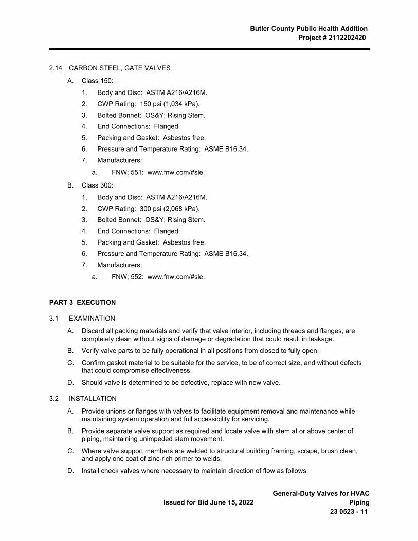
Butler County Public Health Addition Project # 2112202420
Issued for Bid June 15, 2022 General-Duty Valves for HVAC
Piping23 0523 - 11
2.14 CARBON STEEL, GATE VALVES
A. Class 150:
1. Body and Disc: ASTM A216/A216M.2. CWP Rating: 150 psi (1,034 kPa).3. Bolted Bonnet: OS&Y; Rising Stem.4. End Connections: Flanged.5. Packing and Gasket: Asbestos free.6. Pressure and Temperature Rating: ASME B16.34.7. Manufacturers:
a. FNW; 551: www.fnw.com/#sle.
B. Class 300:
1. Body and Disc: ASTM A216/A216M.2. CWP Rating: 300 psi (2,068 kPa).3. Bolted Bonnet: OS&Y; Rising Stem.4. End Connections: Flanged.5. Packing and Gasket: Asbestos free.6. Pressure and Temperature Rating: ASME B16.34.7. Manufacturers:
a. FNW; 552: www.fnw.com/#sle.
PART 3 EXECUTION
3.1 EXAMINATION
A. Discard all packing materials and verify that valve interior, including threads and flanges, are completely clean without signs of damage or degradation that could result in leakage.
B. Verify valve parts to be fully operational in all positions from closed to fully open.
C. Confirm gasket material to be suitable for the service, to be of correct size, and without defects that could compromise effectiveness.
D. Should valve is determined to be defective, replace with new valve.
3.2 INSTALLATION
A. Provide unions or flanges with valves to facilitate equipment removal and maintenance while maintaining system operation and full accessibility for servicing.
B. Provide separate valve support as required and locate valve with stem at or above center of piping, maintaining unimpeded stem movement.
C. Where valve support members are welded to structural building framing, scrape, brush clean, and apply one coat of zinc-rich primer to welds.
D. Install check valves where necessary to maintain direction of flow as follows:
Butler County Public Health Addition Project # 2112202420
General-Duty Valves for HVAC Piping 23 0523 - 12
Issued for Bid June 15, 2022
1. Lift Check: Install with stem plumb and vertical.2. Swing Check: Install horizontal maintaining hinge pin level.3. Orient plate-type and center-guided into horizontal or vertical position, between flanges.
E. Provide chainwheels on operators for valves 4 NPS (100 DN) and larger where located 96 NPS (2400 DN) or more above finished floor, terminating 60 NPS (1520 DN) above finished floor.
END OF SECTION
Butler County Public Health AdditionProject # 2112202420
Issued for Bid June 15, 2022 Hangers and Supports for HVAC
Piping and Equipment23 0529 - 1
SECTION 23 0529 HANGERS AND SUPPORTS FOR HVAC PIPING AND EQUIPMENT
PART 1 GENERAL
1.1 SECTION INCLUDES
A. Provide equipment, materials, labor and supervision necessary to install pipe hangers and supports.
B. Pipe support systems shall secure pipes in place, prevent pipe vibration, provide vertical adjustment for maintaining required grades, and provide for expansion and contraction.
C. Where supports are attached to concrete or other structural members, care shall be taken to prevent damage or weakening of the structural members.
D. Where concrete inserts are to be used, it shall be this Contractor’s responsibility to accurately locate and attach inserts to concrete forms.
1.2 REFERENCES
A. American National Standards Institute, ANSI:
B. ANSI B31.1: Power Piping
C. Manufacturers Standardization Society of the Valve and Fittings Industry, MSS, 1815 North Fort Myer Drive, Arlington, VA 22209.
1. MSS SP-58: Materials Standardization Society: Pipe Hangers and Supports-Materials, Design, and Manufacturer.
2. MSS SP-69: Materials and Standardization Society: Pipe Hangers and Supports - Selection and Application.
3. NFPA 13-Standard for the Installation of Sprinkler Systems.4. ASTM A123-Specification for Zinc Hot-Galvanized Coatings by the Hot Dip Process.5. ASTM A653 G90-Specification for Steel Sheet, Zinc on Iron and Steel.
1.3 SUBMITTALS
A. Submit manufacturer’s product data on all hangers and support devices. Product data to include, but not be limited to materials, finishes, approvals, load ratings, and dimensional information.
PART 2 PRODUCTS
2.1 HANGERS AND SUPPORTS
A. Hangers and support devices shall be Anvil International Inc., Tolco, Fee and Mason, Michigan, B-Line or approved equivalent. Figure numbers based on Anvil.
PART 3 EXECUTION
3.1 INSTALLATION - HORIZONTAL PIPE SUPPORTS
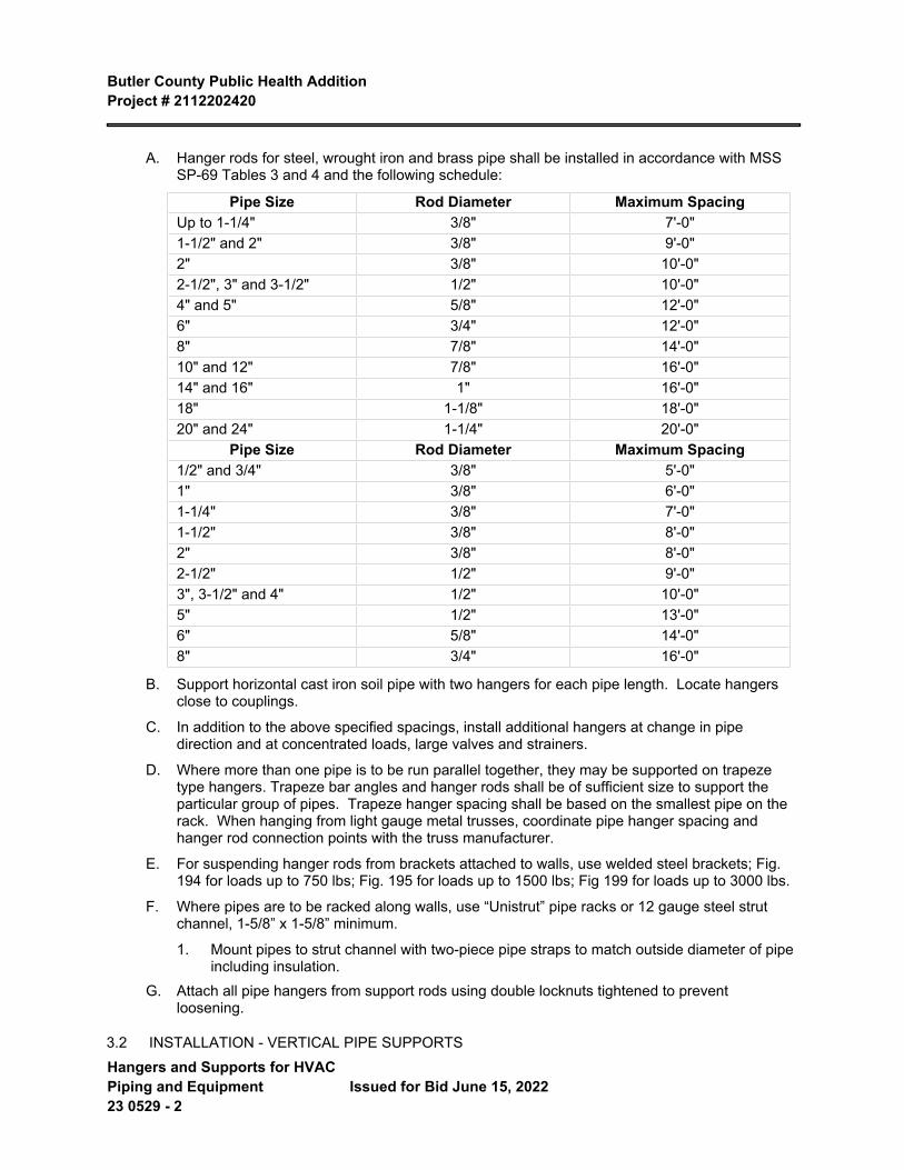
Butler County Public Health Addition Project # 2112202420
Hangers and Supports for HVAC Piping and Equipment 23 0529 - 2
Issued for Bid June 15, 2022
A. Hanger rods for steel, wrought iron and brass pipe shall be installed in accordance with MSS SP-69 Tables 3 and 4 and the following schedule:
Pipe Size Rod Diameter Maximum SpacingUp to 1-1/4" 3/8" 7'-0"1-1/2" and 2" 3/8" 9'-0"2" 3/8" 10'-0"2-1/2", 3" and 3-1/2" 1/2" 10'-0"4" and 5" 5/8" 12'-0"6" 3/4" 12'-0"8" 7/8" 14'-0"10" and 12" 7/8" 16'-0"14" and 16" 1" 16'-0"18" 1-1/8" 18'-0"20" and 24" 1-1/4" 20'-0"
Pipe Size Rod Diameter Maximum Spacing1/2" and 3/4" 3/8" 5'-0"1" 3/8" 6'-0"1-1/4" 3/8" 7'-0"1-1/2" 3/8" 8'-0"2" 3/8" 8'-0"2-1/2" 1/2" 9'-0"3", 3-1/2" and 4" 1/2" 10'-0"5" 1/2" 13'-0"6" 5/8" 14'-0"8" 3/4" 16'-0"
B. Support horizontal cast iron soil pipe with two hangers for each pipe length. Locate hangers close to couplings.
C. In addition to the above specified spacings, install additional hangers at change in pipe direction and at concentrated loads, large valves and strainers.
D. Where more than one pipe is to be run parallel together, they may be supported on trapeze type hangers. Trapeze bar angles and hanger rods shall be of sufficient size to support the particular group of pipes. Trapeze hanger spacing shall be based on the smallest pipe on the rack. When hanging from light gauge metal trusses, coordinate pipe hanger spacing and hanger rod connection points with the truss manufacturer.
E. For suspending hanger rods from brackets attached to walls, use welded steel brackets; Fig. 194 for loads up to 750 lbs; Fig. 195 for loads up to 1500 lbs; Fig 199 for loads up to 3000 lbs.
F. Where pipes are to be racked along walls, use “Unistrut” pipe racks or 12 gauge steel strut channel, 1-5/8” x 1-5/8” minimum.
1. Mount pipes to strut channel with two-piece pipe straps to match outside diameter of pipe including insulation.
G. Attach all pipe hangers from support rods using double locknuts tightened to prevent loosening.
3.2 INSTALLATION - VERTICAL PIPE SUPPORTS
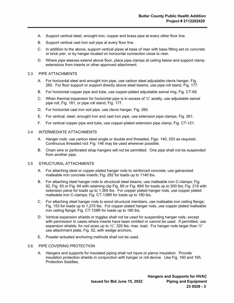
Butler County Public Health Addition Project # 2112202420
Issued for Bid June 15, 2022 Hangers and Supports for HVAC
Piping and Equipment23 0529 - 3
A. Support vertical steel, wrought iron, copper and brass pipe at every other floor line.
B. Support vertical cast iron soil pipe at every floor line.
C. In addition to the above, support vertical pipes at base of riser with base fitting set on concrete or brick pier, or by hanger located on horizontal connection close to riser.
D. Where pipe sleeves extend above floor, place pipe clamps at ceiling below and support clamp extensions from inserts or other approved attachment.
3.3 PIPE ATTACHMENTS
A. For horizontal steel and wrought iron pipe, use carbon steel adjustable clevis hanger, Fig. 260. For floor support or support directly above steel beams, use pipe roll stand, Fig. 177.
B. For horizontal copper pipe and tube, use copper-plated adjustable swivel ring, Fig. CT-69.
C. When thermal expansion for horizontal pipe is in excess of ½” axially, use adjustable swivel pipe roll, Fig. 181, or pipe roll stand, Fig. 177.
D. For horizontal cast iron soil pipe, use clevis hanger, Fig. 260.
E. For vertical, steel, wrought iron and cast iron pipe, use extension pipe clamps, Fig. 261.
F. For vertical copper pipe and tube, use copper-plated extension pipe clamp, Fig. CT-121.
3.4 INTERMEDIATE ATTACHMENTS
A. Hanger rods: use carbon steel single or double end threaded, Figs. 140, 253 as required. Continuous threaded rod: Fig. 146 may be used wherever possible.
B. Chain wire or perforated strap hangers will not be permitted. One pipe shall not be suspended from another pipe.
3.5 STRUCTURAL ATTACHMENTS
A. For attaching steel or copper plated hanger rods to reinforced concrete, use galvanized malleable iron concrete inserts; Fig. 282 for loads up to 1140 lbs.
B. For attaching steel hanger rods to structural steel beams, use malleable iron C-clamps; Fig. 92, Fig. 93 or Fig. 94 with retaining clip Fig. 89 or Fig. 89X for loads up to 500 lbs; Fig. 218 with extension piece for loads up to 1,365 lbs. For copper plated hanger rods, use copper plated malleable iron C-clamps; Fig. CT-138R for loads up to 180 lbs.
C. For attaching steel hanger rods to wood structural members, use malleable iron ceiling flange; Fig. 153 for loads up to 1,270 lbs. For copper plated hanger rods, use copper plated malleable iron ceiling flange: Fig. CT-128R for loads up to 180 lbs.
D. Vertical expansion shields or toggles shall not be used for suspending hanger rods, except with permission in cases where inserts have been omitted or cannot be used. If permitted, use expansion shields; for rod sizes up to ½”, 320 lbs. max. load. For hanger rods larger than ½” use attachment plate, Fig. 52, with wedge anchors.
E. Powder actuated anchoring methods shall not be used.
3.6 PIPE COVERING PROTECTION
A. Hangers and supports for insulated piping shall not injure or pierce insulation. Provide insulation protection shields in conjunction with hanger or roll device. Use Fig. 160 and 165, Protection Saddles.
Butler County Public Health Addition Project # 2112202420
Hangers and Supports for HVAC Piping and Equipment 23 0529 - 4
Issued for Bid June 15, 2022
3.7 SUPPLEMENTAL STEEL
A. Provide supplemental steel required to hang or support mechanical equipment or piping.
END OF SECTION 23 0529
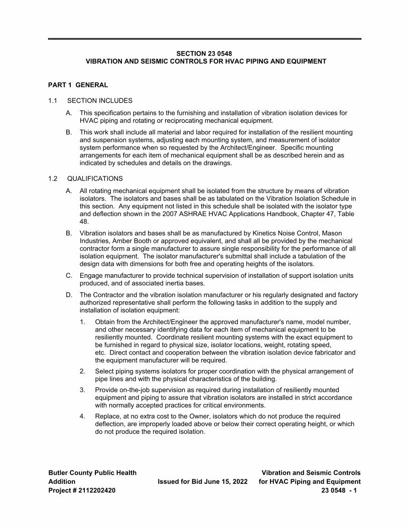
Butler County Public Health AdditionProject # 2112202420
Issued for Bid June 15, 2022 Vibration and Seismic Controls
for HVAC Piping and Equipment23 0548 - 1
SECTION 23 0548 VIBRATION AND SEISMIC CONTROLS FOR HVAC PIPING AND EQUIPMENT
PART 1 GENERAL
1.1 SECTION INCLUDES
A. This specification pertains to the furnishing and installation of vibration isolation devices for HVAC piping and rotating or reciprocating mechanical equipment.
B. This work shall include all material and labor required for installation of the resilient mounting and suspension systems, adjusting each mounting system, and measurement of isolator system performance when so requested by the Architect/Engineer. Specific mounting arrangements for each item of mechanical equipment shall be as described herein and as indicated by schedules and details on the drawings.
1.2 QUALIFICATIONS
A. All rotating mechanical equipment shall be isolated from the structure by means of vibration isolators. The isolators and bases shall be as tabulated on the Vibration Isolation Schedule in this section. Any equipment not listed in this schedule shall be isolated with the isolator type and deflection shown in the 2007 ASHRAE HVAC Applications Handbook, Chapter 47, Table 48.
B. Vibration isolators and bases shall be as manufactured by Kinetics Noise Control, Mason Industries, Amber Booth or approved equivalent, and shall all be provided by the mechanical contractor form a single manufacturer to assure single responsibility for the performance of all isolation equipment. The isolator manufacturer's submittal shall include a tabulation of the design data with dimensions for both free and operating heights of the isolators.
C. Engage manufacturer to provide technical supervision of installation of support isolation units produced, and of associated inertia bases.
D. The Contractor and the vibration isolation manufacturer or his regularly designated and factory authorized representative shall perform the following tasks in addition to the supply and installation of isolation equipment:
1. Obtain from the Architect/Engineer the approved manufacturer's name, model number, and other necessary identifying data for each item of mechanical equipment to be resiliently mounted. Coordinate resilient mounting systems with the exact equipment to be furnished in regard to physical size, isolator locations, weight, rotating speed, etc. Direct contact and cooperation between the vibration isolation device fabricator and the equipment manufacturer will be required.
2. Select piping systems isolators for proper coordination with the physical arrangement of pipe lines and with the physical characteristics of the building.
3. Provide on-the-job supervision as required during installation of resiliently mounted equipment and piping to assure that vibration isolators are installed in strict accordance with normally accepted practices for critical environments.
4. Replace, at no extra cost to the Owner, isolators which do not produce the required deflection, are improperly loaded above or below their correct operating height, or which do not produce the required isolation.
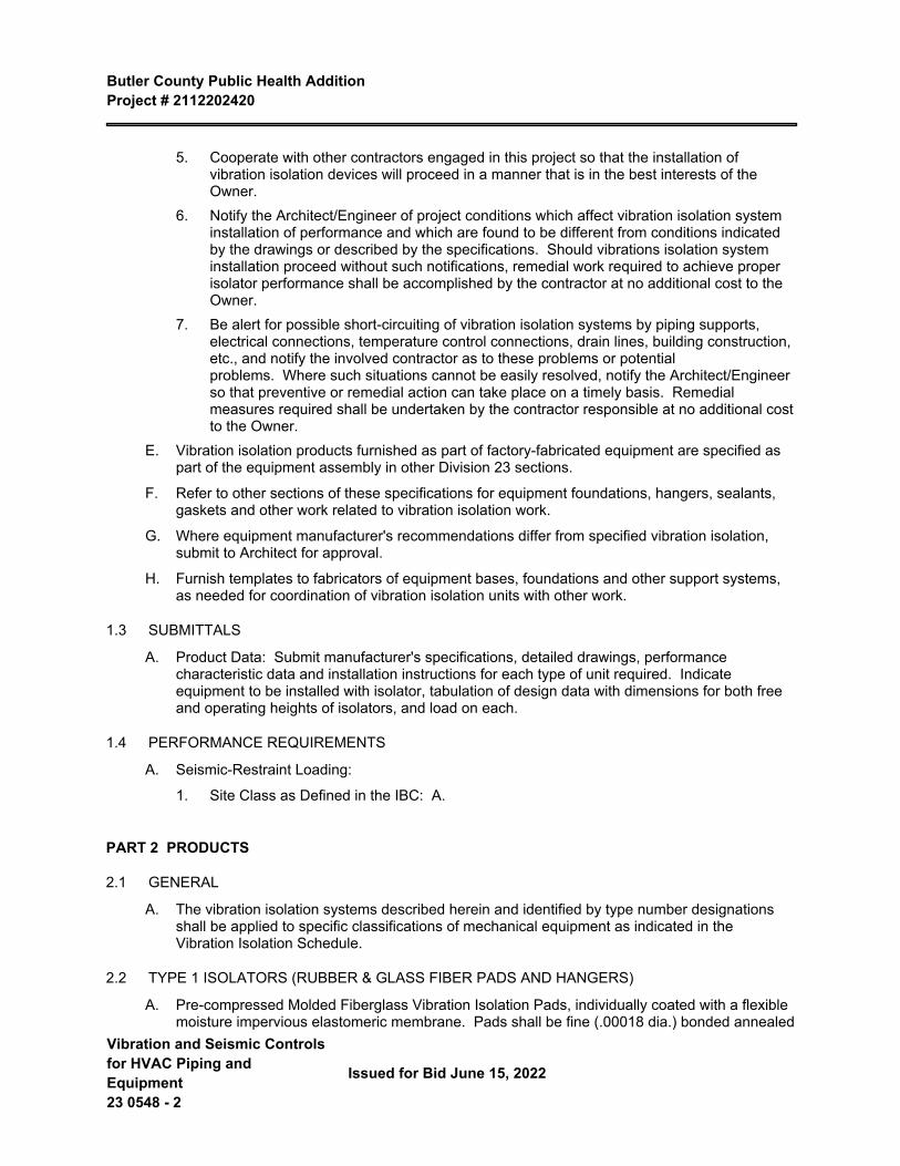
Butler County Public Health Addition Project # 2112202420
Vibration and Seismic Controls for HVAC Piping and Equipment 23 0548 - 2
Issued for Bid June 15, 2022
5. Cooperate with other contractors engaged in this project so that the installation of vibration isolation devices will proceed in a manner that is in the best interests of the Owner.
6. Notify the Architect/Engineer of project conditions which affect vibration isolation system installation of performance and which are found to be different from conditions indicated by the drawings or described by the specifications. Should vibrations isolation system installation proceed without such notifications, remedial work required to achieve proper isolator performance shall be accomplished by the contractor at no additional cost to the Owner.
7. Be alert for possible short-circuiting of vibration isolation systems by piping supports, electrical connections, temperature control connections, drain lines, building construction, etc., and notify the involved contractor as to these problems or potential problems. Where such situations cannot be easily resolved, notify the Architect/Engineer so that preventive or remedial action can take place on a timely basis. Remedial measures required shall be undertaken by the contractor responsible at no additional cost to the Owner.
E. Vibration isolation products furnished as part of factory-fabricated equipment are specified as part of the equipment assembly in other Division 23 sections.
F. Refer to other sections of these specifications for equipment foundations, hangers, sealants, gaskets and other work related to vibration isolation work.
G. Where equipment manufacturer's recommendations differ from specified vibration isolation, submit to Architect for approval.
H. Furnish templates to fabricators of equipment bases, foundations and other support systems, as needed for coordination of vibration isolation units with other work.
1.3 SUBMITTALS
A. Product Data: Submit manufacturer's specifications, detailed drawings, performance characteristic data and installation instructions for each type of unit required. Indicate equipment to be installed with isolator, tabulation of design data with dimensions for both free and operating heights of isolators, and load on each.
1.4 PERFORMANCE REQUIREMENTS
A. Seismic-Restraint Loading:
1. Site Class as Defined in the IBC: A.
PART 2 PRODUCTS
2.1 GENERAL
A. The vibration isolation systems described herein and identified by type number designations shall be applied to specific classifications of mechanical equipment as indicated in the Vibration Isolation Schedule.
2.2 TYPE 1 ISOLATORS (RUBBER & GLASS FIBER PADS AND HANGERS)
A. Pre-compressed Molded Fiberglass Vibration Isolation Pads, individually coated with a flexible moisture impervious elastomeric membrane. Pads shall be fine (.00018 dia.) bonded annealed
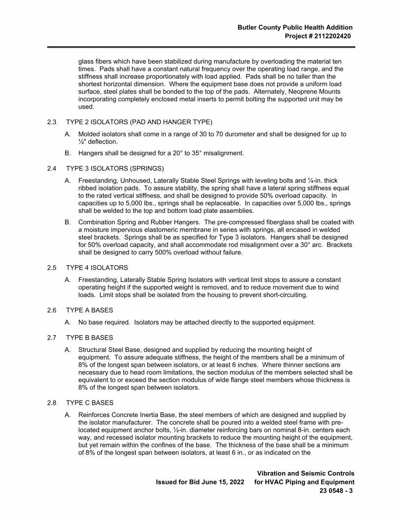
Butler County Public Health Addition Project # 2112202420
Issued for Bid June 15, 2022 Vibration and Seismic Controls
for HVAC Piping and Equipment23 0548 - 3
glass fibers which have been stabilized during manufacture by overloading the material ten times. Pads shall have a constant natural frequency over the operating load range, and the stiffness shall increase proportionately with load applied. Pads shall be no taller than the shortest horizontal dimension. Where the equipment base does not provide a uniform load surface, steel plates shall be bonded to the top of the pads. Alternately, Neoprene Mounts incorporating completely enclosed metal inserts to permit bolting the supported unit may be used.
2.3 TYPE 2 ISOLATORS (PAD AND HANGER TYPE)
A. Molded isolators shall come in a range of 30 to 70 durometer and shall be designed for up to ½" deflection.
B. Hangers shall be designed for a 20° to 35° misalignment.
2.4 TYPE 3 ISOLATORS (SPRINGS)
A. Freestanding, Unhoused, Laterally Stable Steel Springs with leveling bolts and ¼-in. thick ribbed isolation pads. To assure stability, the spring shall have a lateral spring stiffness equal to the rated vertical stiffness, and shall be designed to provide 50% overload capacity. In capacities up to 5,000 lbs., springs shall be replaceable. In capacities over 5,000 lbs., springs shall be welded to the top and bottom load plate assemblies.
B. Combination Spring and Rubber Hangers. The pre-compressed fiberglass shall be coated with a moisture impervious elastomeric membrane in series with springs, all encased in welded steel brackets. Springs shall be as specified for Type 3 isolators. Hangers shall be designed for 50% overload capacity, and shall accommodate rod misalignment over a 30° arc. Brackets shall be designed to carry 500% overload without failure.
2.5 TYPE 4 ISOLATORS
A. Freestanding, Laterally Stable Spring Isolators with vertical limit stops to assure a constant operating height if the supported weight is removed, and to reduce movement due to wind loads. Limit stops shall be isolated from the housing to prevent short-circuiting.
2.6 TYPE A BASES
A. No base required. Isolators may be attached directly to the supported equipment.
2.7 TYPE B BASES
A. Structural Steel Base, designed and supplied by reducing the mounting height of equipment. To assure adequate stiffness, the height of the members shall be a minimum of 8% of the longest span between isolators, or at least 6 inches. Where thinner sections are necessary due to head room limitations, the section modulus of the members selected shall be equivalent to or exceed the section modulus of wide flange steel members whose thickness is 8% of the longest span between isolators.
2.8 TYPE C BASES
A. Reinforces Concrete Inertia Base, the steel members of which are designed and supplied by the isolator manufacturer. The concrete shall be poured into a welded steel frame with pre-located equipment anchor bolts, ½-in. diameter reinforcing bars on nominal 8-in. centers each way, and recessed isolator mounting brackets to reduce the mounting height of the equipment, but yet remain within the confines of the base. The thickness of the base shall be a minimum of 8% of the longest span between isolators, at least 6 in., or as indicated on the
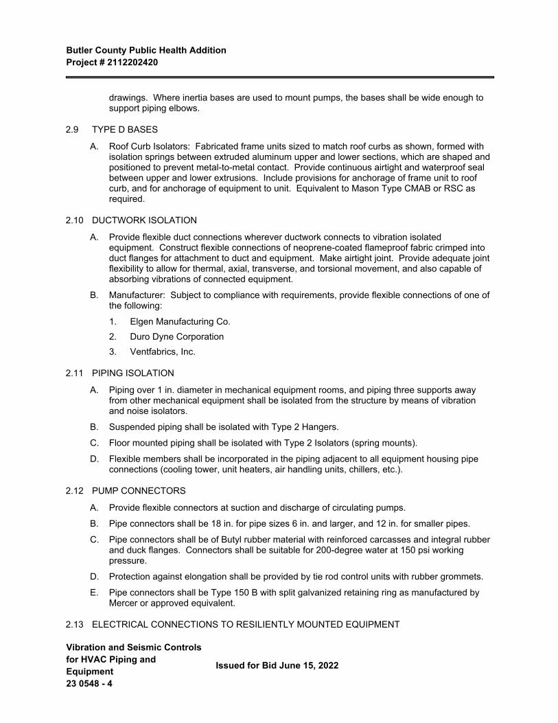
Butler County Public Health Addition Project # 2112202420
Vibration and Seismic Controls for HVAC Piping and Equipment 23 0548 - 4
Issued for Bid June 15, 2022
drawings. Where inertia bases are used to mount pumps, the bases shall be wide enough to support piping elbows.
2.9 TYPE D BASES
A. Roof Curb Isolators: Fabricated frame units sized to match roof curbs as shown, formed with isolation springs between extruded aluminum upper and lower sections, which are shaped and positioned to prevent metal-to-metal contact. Provide continuous airtight and waterproof seal between upper and lower extrusions. Include provisions for anchorage of frame unit to roof curb, and for anchorage of equipment to unit. Equivalent to Mason Type CMAB or RSC as required.
2.10 DUCTWORK ISOLATION
A. Provide flexible duct connections wherever ductwork connects to vibration isolated equipment. Construct flexible connections of neoprene-coated flameproof fabric crimped into duct flanges for attachment to duct and equipment. Make airtight joint. Provide adequate joint flexibility to allow for thermal, axial, transverse, and torsional movement, and also capable of absorbing vibrations of connected equipment.
B. Manufacturer: Subject to compliance with requirements, provide flexible connections of one of the following:
1. Elgen Manufacturing Co.2. Duro Dyne Corporation3. Ventfabrics, Inc.
2.11 PIPING ISOLATION
A. Piping over 1 in. diameter in mechanical equipment rooms, and piping three supports away from other mechanical equipment shall be isolated from the structure by means of vibration and noise isolators.
B. Suspended piping shall be isolated with Type 2 Hangers.
C. Floor mounted piping shall be isolated with Type 2 Isolators (spring mounts).
D. Flexible members shall be incorporated in the piping adjacent to all equipment housing pipe connections (cooling tower, unit heaters, air handling units, chillers, etc.).
2.12 PUMP CONNECTORS
A. Provide flexible connectors at suction and discharge of circulating pumps.
B. Pipe connectors shall be 18 in. for pipe sizes 6 in. and larger, and 12 in. for smaller pipes.
C. Pipe connectors shall be of Butyl rubber material with reinforced carcasses and integral rubber and duck flanges. Connectors shall be suitable for 200-degree water at 150 psi working pressure.
D. Protection against elongation shall be provided by tie rod control units with rubber grommets.
E. Pipe connectors shall be Type 150 B with split galvanized retaining ring as manufactured by Mercer or approved equivalent.
2.13 ELECTRICAL CONNECTIONS TO RESILIENTLY MOUNTED EQUIPMENT
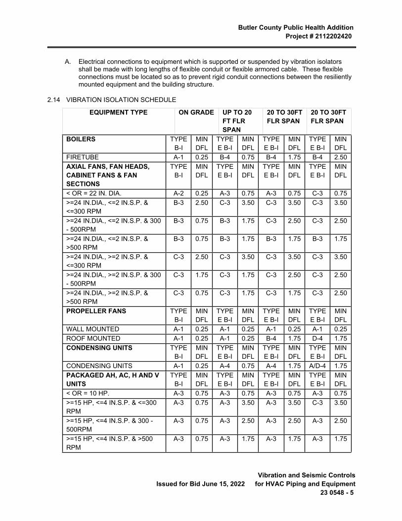
Butler County Public Health Addition Project # 2112202420
Issued for Bid June 15, 2022 Vibration and Seismic Controls
for HVAC Piping and Equipment23 0548 - 5
A. Electrical connections to equipment which is supported or suspended by vibration isolators shall be made with long lengths of flexible conduit or flexible armored cable. These flexible connections must be located so as to prevent rigid conduit connections between the resiliently mounted equipment and the building structure.
2.14 VIBRATION ISOLATION SCHEDULE
EQUIPMENT TYPE ON GRADE UP TO 20 FT FLR SPAN
20 TO 30FT FLR SPAN
20 TO 30FT FLR SPAN
BOILERS TYPE B-I
MIN DFL
TYPE E B-I
MIN DFL
TYPE E B-I
MIN DFL
TYPE E B-I
MIN DFL
FIRETUBE A-1 0.25 B-4 0.75 B-4 1.75 B-4 2.50AXIAL FANS, FAN HEADS, CABINET FANS & FAN SECTIONS
TYPE B-I
MIN DFL
TYPE E B-I
MIN DFL
TYPE E B-I
MIN DFL
TYPE E B-I
MIN DFL
< OR = 22 IN. DIA. A-2 0.25 A-3 0.75 A-3 0.75 C-3 0.75>=24 IN.DIA., <=2 IN.S.P. & <=300 RPM
B-3 2.50 C-3 3.50 C-3 3.50 C-3 3.50
>=24 IN.DIA., <=2 IN.S.P. & 300 - 500RPM
B-3 0.75 B-3 1.75 C-3 2.50 C-3 2.50
>=24 IN.DIA., <=2 IN.S.P. & >500 RPM
B-3 0.75 B-3 1.75 B-3 1.75 B-3 1.75
>=24 IN.DIA., >=2 IN.S.P. & <=300 RPM
C-3 2.50 C-3 3.50 C-3 3.50 C-3 3.50
>=24 IN.DIA., >=2 IN.S.P. & 300 - 500RPM
C-3 1.75 C-3 1.75 C-3 2.50 C-3 2.50
>=24 IN.DIA., >=2 IN.S.P. & >500 RPM
C-3 0.75 C-3 1.75 C-3 1.75 C-3 2.50
PROPELLER FANS TYPE B-I
MIN DFL
TYPE E B-I
MIN DFL
TYPE E B-I
MIN DFL
TYPE E B-I
MIN DFL
WALL MOUNTED A-1 0.25 A-1 0.25 A-1 0.25 A-1 0.25ROOF MOUNTED A-1 0.25 A-1 0.25 B-4 1.75 D-4 1.75CONDENSING UNITS TYPE
B-IMIN DFL
TYPE E B-I
MIN DFL
TYPE E B-I
MIN DFL
TYPE E B-I
MIN DFL
CONDENSING UNITS A-1 0.25 A-4 0.75 A-4 1.75 A/D-4 1.75PACKAGED AH, AC, H AND V UNITS
TYPE B-I
MIN DFL
TYPE E B-I
MIN DFL
TYPE E B-I
MIN DFL
TYPE E B-I
MIN DFL
< OR = 10 HP. A-3 0.75 A-3 0.75 A-3 0.75 A-3 0.75>=15 HP, <=4 IN.S.P. & <=300 RPM
A-3 0.75 A-3 3.50 A-3 3.50 C-3 3.50
>=15 HP, <=4 IN.S.P. & 300 - 500RPM
A-3 0.75 A-3 2.50 A-3 2.50 A-3 2.50
>=15 HP, <=4 IN.S.P. & >500 RPM
A-3 0.75 A-3 1.75 A-3 1.75 A-3 1.75

Butler County Public Health Addition Project # 2112202420
Vibration and Seismic Controls for HVAC Piping and Equipment 23 0548 - 6
Issued for Bid June 15, 2022
>=15 HP, >=4 IN.S.P. & <=300 RPM
B-3 0.75 C-3 3.50 C-3 3.50 C-3 3.50
>=15 HP, >=4 IN.S.P. & 300 - 500RPM
B-3 0.75 C-3 1.75 C-3 2.50 C-3 2.50
>=15 HP, >=4 IN.S.P. & >500 RPM
B-3 0.75 C-3 1.75 C-3 1.75 C-3 2.50
BASE TYPES: ISOLATOR TYPES:A. NO BASE, ISOLATORS ATTACHED DIRECTLY TO EQUIPMENT
1. PAD, RUBBER, OR GLASS FIBER
B. +PAD, RUBBER, OR GLASS FIBER 2. RUBBER FLOOR ISOLATOR OR HANGER
C. CONCRETE INERTIA BASE 3. SPRING FLOOR ISOLATOR OR HANGER
D. CURB-MOUNTED BASE 4. RESTRAINED SPRING ISOLATOR5. THRUST RESTRAINT (SEE ASHRAE HANDBOOK)
PART 3 INSTALLATION
3.1 EXECUTION
A. General: Except as otherwise indicated, comply with manufacturer's instructions for the installation and load application to vibration isolation materials and units. Adjust to ensure that units do not exceed rated operating deflections or bottom out under loading, and are not short-circuited by other contacts or bearing points. Remove space blocks and similar devices (if any) intended for temporary protection against overloading during installation.
B. Anchor and attach units to substrate and equipment as required for secure operation and to prevent displacement by normal forces, and as indicated.
C. Adjust leveling devices as required to distribute loading uniformly onto isolators. Shim units as required where leveling devices cannot be used to distribute loading properly.
D. Flexible Pipe Connectors: Refer to other section of these Specifications for the installation of flexible pipe connectors.
E. Install vibration isolators that are furnished with equipment.
END OF SECTION 23 0548
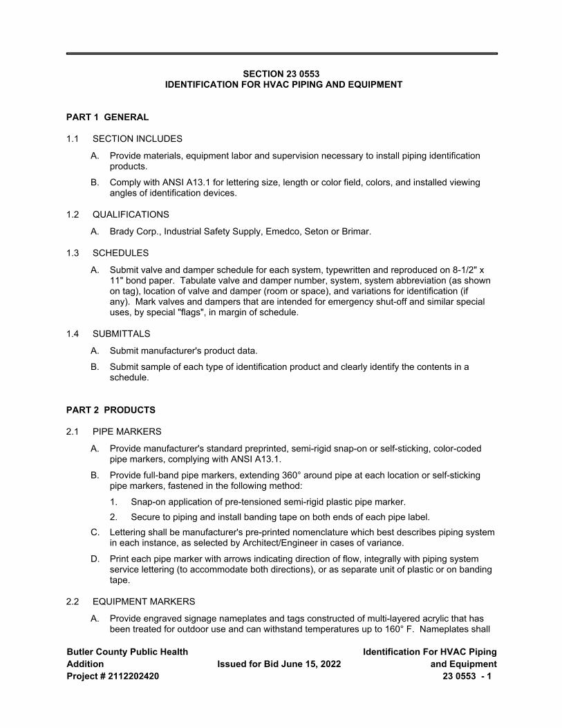
Butler County Public Health AdditionProject # 2112202420
Issued for Bid June 15, 2022 Identification For HVAC Piping
and Equipment23 0553 - 1
SECTION 23 0553 IDENTIFICATION FOR HVAC PIPING AND EQUIPMENT
PART 1 GENERAL
1.1 SECTION INCLUDES
A. Provide materials, equipment labor and supervision necessary to install piping identification products.
B. Comply with ANSI A13.1 for lettering size, length or color field, colors, and installed viewing angles of identification devices.
1.2 QUALIFICATIONS
A. Brady Corp., Industrial Safety Supply, Emedco, Seton or Brimar.
1.3 SCHEDULES
A. Submit valve and damper schedule for each system, typewritten and reproduced on 8-1/2" x 11" bond paper. Tabulate valve and damper number, system, system abbreviation (as shown on tag), location of valve and damper (room or space), and variations for identification (if any). Mark valves and dampers that are intended for emergency shut-off and similar special uses, by special "flags", in margin of schedule.
1.4 SUBMITTALS
A. Submit manufacturer's product data.
B. Submit sample of each type of identification product and clearly identify the contents in a schedule.
PART 2 PRODUCTS
2.1 PIPE MARKERS
A. Provide manufacturer's standard preprinted, semi-rigid snap-on or self-sticking, color-coded pipe markers, complying with ANSI A13.1.
B. Provide full-band pipe markers, extending 360° around pipe at each location or self-sticking pipe markers, fastened in the following method:
1. Snap-on application of pre-tensioned semi-rigid plastic pipe marker.2. Secure to piping and install banding tape on both ends of each pipe label.
C. Lettering shall be manufacturer's pre-printed nomenclature which best describes piping system in each instance, as selected by Architect/Engineer in cases of variance.
D. Print each pipe marker with arrows indicating direction of flow, integrally with piping system service lettering (to accommodate both directions), or as separate unit of plastic or on banding tape.
2.2 EQUIPMENT MARKERS
A. Provide engraved signage nameplates and tags constructed of multi-layered acrylic that has been treated for outdoor use and can withstand temperatures up to 160° F. Nameplates shall
Butler County Public Health Addition Project # 2112202420
Identification For HVAC Piping and Equipment 23 0553 - 2
Issued for Bid June 15, 2022
have beveled edges with contrasting color core, letters, and border. Minimum size of nameplate shall be 3" high by 6" long. The minimum letter height shall be 3/4". Attachment shall be by double faced 2 mil permanent acrylic adhesive. For equipment that doesn't allow for direct attachment, furnish sheet metal backing to integrate with equipment such that signage can be read from 5 feet above the finished floor. Unless noted otherwise, signage shall be provided with black lettering, black border, and yellow core. All signage shall include up to 14 characters per line, minimum of 3 lines per tag. Furnish signage for equipment shown in Section 3:
1. All pumps shall include the full name description for system served such as "Primary Chilled Water Pump – 1."
2. All air handling unit filter sections shall be labeled with the exact quantity of filters, size, and type of filter such as "14 – 24"x24"x2", 30% Pleated Filters."
B. All equipment shall be named consistent with the plans and specifications as indicated on the schedules or as directed by the Owner.
2.3 BRASS VALVE AND DAMPER TAGS
A. Provide manufacturer's standard brass valve and damper tags with stamped black filled lettering, with piping system abbreviation in 1/4" high letters and sequenced valve numbers 1/2" high, and with 3/16" hole for fastener.
B. Provide 1-1/2" round brass tags with black lettering. Seton 250 BL or equal.
2.4 VALVE AND DAMPER TAG FASTENERS
A. Manufacturer's standard solid brass chain or solid brass S-hooks of sizes required for proper attachment of tags to valves and dampers, and manufactured specifically for that purpose.
2.5 VALVE AND DAMPER SCHEDULE FRAMES
A. For each page of schedule, provide glazed display frame, with screws for removable mounting on masonry walls. Provide frames of finished hardwood or extruded aluminum, with SSD-grade sheet glass.
PART 3 EXECUTION
3.1 INSTALLATION OF MECHANICAL IDENTIFICATION
A. Where identification is to be applied to surfaces that require insulation, painting or other covering or finish, including valve tags in finished mechanical spaces, install identification after completion of covering and painting. Install identification prior to installation of acoustical ceilings and similar removable concealment.
B. Install pipe markers on each system, and include arrows to show normal direction of flow.
C. Locate pipe markers as follows: wherever piping is exposed to view in occupied spaces, machine rooms, accessible maintenance spaces (shafts, tunnels, plenums) above lay-in type ceilings and exterior non-concealed locations.
1. Near each valve and control device.2. Near each branch, excluding short take-offs for fixtures, mark each pipe at branch where
there could be question of flow pattern.
Butler County Public Health Addition Project # 2112202420
Issued for Bid June 15, 2022 Identification For HVAC Piping
and Equipment23 0553 - 3
3. Near locations where pipes pass through walls or floors/ceilings, (both sides) or center non-accessible enclosures.
4. At access doors, manholes, and similar access points that permit view of concealed piping.
5. Near major equipment items and other points of origination and termination.6. At each pipe passage to underground.7. Spaced intermediately at maximum spacing of 50' along each piping run, except reduce
spacing to 25' in congested areas of piping and equipment.8. On piping above removable acoustical ceilings, maximum spacing of 20' along each
piping run.9. Where self-sticking labels are used, the pipe or its covering surface shall be properly
prepared. This consists of removal of loose dirt, oil and grease, loose paint or peeling insulation covering. This can be done with a brush and cloth; washing is not required. Use solvent for removal of oil or grease.
10. Banding tape must be used on both ends of all self-sticking labels. The tape shall encircle the pipe completely and overlap itself so the banding tape can adhere to itself.
D. Provide valve tags for all major valves 3/4" size or larger. Included are all main, zone and branch valves, valves in all equipment rooms, etc. All types of valves, ball, globe, butterfly, cocks, control, regulating, relief, reducing, solenoid, etc. are to be identified except check valves. Do not identify end use point valves for plumbing fixtures, and similar rough-in connections.
E. Provide damper tags on all automatic control dampers, motorized dampers, and smoke dampers.
F. List each tagged valve and damper in schedule for each system showing function and location. Provide separate charts for mechanical divisions of work. Charts shall be installed on a conspicuous wall in the main mechanical equipment room. Provide unframed copies of valve and damper lists as part of closeout documents.
3.2 ADJUSTING AND CLEANING
A. Relocate any mechanical identification device which has become visually blocked by work of this division or other divisions.
B. Clean face of identification devices and glass frames of valve schedules.
3.3 PIPING DUCTWORK, AND EQUIPMENT IDENTIFICATION
A. Piping systems that shall be identified by their controls (including directional arrows) on this project shall include, but are not necessarily limited to, the following:
1. Heating water (supply and return).B. Equipment/Ductwork
1. Pumps.2. Exhaust fans.3. Directional arrows indicating flow of air at discharge and inlet of air handling units.4. Provide name plates for all equipment scheduled on the drawings. Coordinate nameplate
tag with Owner's sequencing system. If the Owner has no preference, the nameplates shall correspond with the equipment schedule.

Butler County Public Health Addition Project # 2112202420
Identification For HVAC Piping and Equipment 23 0553 - 4
Issued for Bid June 15, 2022
5. All labeling for the machinery refrigeration room shall be in accordance with ASHRAE 15.
END OF SECTION 23 0553
Butler County Public Health AdditionProject # 2112202420
Issued for Bid June 15, 2022 Testing, Adjusting, and Balancing
for HVAC23 0593 - 1
SECTION 23 0593 TESTING, ADJUSTING, AND BALANCING FOR HVAC
PART 1 GENERAL
1.1 SECTION INCLUDES
A. Testing, adjustment, and balancing of air systems.
B. Testing, adjustment, and balancing of hydronic, steam, and refrigerating systems.
1.2 RELATED REQUIREMENTS
A. Section 01 4000 - Quality Requirements: Employment of testing agency and payment for services.
1.3 REFERENCE STANDARDS
A. AABC (NSTSB) - AABC National Standards for Total System Balance, 7th Edition 2016.
B. ASHRAE Std 110 - Methods of Testing Performance of Laboratory Fume Hoods 2016, with Errata.
C. ASHRAE Std 111 - Measurement, Testing, Adjusting, and Balancing of Building HVAC Systems 2008, with Errata (2019).
D. NEBB (TAB) - Procedural Standards for Testing Adjusting and Balancing of Environmental Systems 2015, with Errata (2017).
E. SMACNA (TAB) - HVAC Systems Testing, Adjusting and Balancing 2002.
1.4 SUBMITTALS
A. See Section 01 3000 - Administrative Requirements, for submittal procedures.
B. TAB Plan: Submit a written plan indicating the testing, adjusting, and balancing standard to be followed and the specific approach for each system and component.
1. Submit to Engineer/Engineer.2. Submit to the Commissioning Authority.3. Submit six weeks prior to starting the testing, adjusting, and balancing work.4. Include certification that the plan developer has reviewed Contract Documents, the equipment
and systems, and the control system with the Engineer and other installers to sufficiently understand the design intent for each system.
5. Include at least the following in the plan:
a. List of all air flow, water flow, sound level, system capacity and efficiency measurements to be performed and a description of specific test procedures, parameters, formulas to be used.
b. Copy of field checkout sheets and logs to be used, listing each piece of equipment to be tested, adjusted and balanced with the data cells to be gathered for each.
c. Discussion of what notations and markings will be made on the duct and piping drawings during the process.
Butler County Public Health Addition Project # 2112202420
Testing, Adjusting, and Balancing for HVAC 23 0593 - 2
Issued for Bid June 15, 2022
d. Final test report forms to be used.
e. Detailed step-by-step procedures for TAB work for each system and issue, including:
1) Terminal flow calibration (for each terminal type).2) Diffuser proportioning.3) Branch/submain proportioning.4) Total flow calculations.5) Rechecking.6) Diversity issues.
f. Expected problems and solutions, etc.
g. Criteria for using air flow straighteners or relocating flow stations and sensors; analogous explanations for the water side.
h. Details of how TOTAL flow will be determined; for example:
1) Air: Sum of terminal flows via control system calibrated readings or via hood readings of all terminals, supply (SA) and return air (RA) pitot traverse, SA or RA flow stations.
2) Water: Pump curves, circuit setter, flow station, ultrasonic, etc.
i. Specific procedures that will ensure that both air and water side are operating at the lowest possible pressures and methods to verify this.
j. Confirmation of understanding of the outside air ventilation criteria under all conditions.
k. Method of verifying and setting minimum outside air flow rate will be verified and set and for what level (total building, zone, etc.).
l. Method of checking building static and exhaust fan and/or relief damper capacity.
m. Proposed selection points for sound measurements and sound measurement methods.
n. Methods for making coil or other system plant capacity measurements, if specified.
o. Time schedule for TAB work to be done in phases (by floor, etc.).
p. Description of TAB work for areas to be built out later, if any.
q. Time schedule for deferred or seasonal TAB work, if specified.
r. False loading of systems to complete TAB work, if specified.
s. Exhaust fan balancing and capacity verifications, including any required room pressure differentials.
t. Interstitial cavity differential pressure measurements and calculations, if specified.
u. Procedures for field technician logs of discrepancies, deficient or uncompleted work by others, contract interpretation requests and lists of completed tests (scope and frequency).
v. Procedures for formal progress reports, including scope and frequency.
Butler County Public Health Addition Project # 2112202420
Issued for Bid June 15, 2022 Testing, Adjusting, and Balancing
for HVAC23 0593 - 3
w. Procedures for formal deficiency reports, including scope, frequency and distribution.
C. Field Logs: Submit at least twice a week to the Commissioning Authority.
D. Control System Coordination Reports: Communicate in writing to the controls installer all setpoint and parameter changes made or problems and discrepancies identified during TAB that affect, or could affect, the control system setup and operation.
E. Progress Reports.
F. Final Report: Indicate deficiencies in systems that would prevent proper testing, adjusting, and balancing of systems and equipment to achieve specified performance.
1. Submit under provisions of Section 01 4000.2. Submit to the Commissioning Authority within two weeks after completion of testing, adjusting,
and balancing.3. Revise TAB plan to reflect actual procedures and submit as part of final report.4. Submit draft copies of report for review prior to final acceptance of Project. Provide final copies
for Engineer and for inclusion in operating and maintenance manuals.5. Provide report in PDF, Excel, or Word format, complete with cover page.6. Include set of reduced drawings with air outlets and equipment identified to correspond with data
sheets.7. Include set of reduced drawings indicating thermostat locations.8. Include actual instrument list, with manufacturer name, serial number, and date of calibration.9. Form of Test Reports: Where the TAB standard being followed recommends a report format use
that; otherwise, follow ASHRAE Std 111.10. Units of Measure: Report data in both I-P (inch-pound) and SI (metric) units.11. Include the following on the title page of each report:
a. Name of Testing, Adjusting, and Balancing Agency.
b. Address of Testing, Adjusting, and Balancing Agency.
c. Telephone number of Testing, Adjusting, and Balancing Agency.
d. Project name.
e. Project location.
f. Project Engineer.
g. Project Engineer.
h. Project Contractor.
i. Project altitude.
j. Report date.
G. Project Record Documents: Record actual locations of flow measuring stations and balancing valves and rough setting.
PART 2 PRODUCTS - NOT USED
Butler County Public Health Addition Project # 2112202420
Testing, Adjusting, and Balancing for HVAC 23 0593 - 4
Issued for Bid June 15, 2022
PART 3 EXECUTION
3.1 GENERAL REQUIREMENTS
A. Perform total system balance in accordance with one of the following:
1. AABC (NSTSB), AABC National Standards for Total System Balance.2. SMACNA (TAB).
B. Begin work after completion of systems to be tested, adjusted, or balanced and complete work prior to Substantial Completion of the project.
C. Where HVAC systems and/or components interface with life safety systems, including fire and smoke detection, alarm, and control, coordinate scheduling and testing and inspection procedures with the authorities having jurisdiction.
D. TAB Agency Qualifications:
1. Company specializing in the testing, adjusting, and balancing of systems specified in this section.2. Having minimum of three years documented experience.3. Certified by one of the following:
a. AABC, Associated Air Balance Council: upon completion submit AABC National Performance Guaranty.
b. NEBB, National Environmental Balancing Bureau: www.nebb.org/#sle.
c. TABB, The Testing, Adjusting, and Balancing Bureau of National Energy Management Institute: www.tabbcertified.org/#sle.
E. TAB Supervisor and Technician Qualifications: Certified by same organization as TAB agency.
F. OTHER CONTRACTOR RESPONSIBILITIES
1. Including balancing dampers as required by the Drawings and Specifications.2. Putting complete system into operation during duration of balancing period.3. Providing up-to-date set of Drawings and advising immediately of changes made to the system
during construction.4. Providing labor and equipment and cost of performing corrections such as dampers, belts, and
pulley changes, etc. as required without undue delay.5. Providing complete submittal information for mechanical equipment complete with pertinent
engineering information.
3.2 EXAMINATION
A. Verify that systems are complete and operable before commencing work. Ensure the following conditions:
1. Systems are started and operating in a safe and normal condition.2. Temperature control systems are installed complete and operable.3. Proper thermal overload protection is in place for electrical equipment.4. Final filters are clean and in place. If required, install temporary media in addition to final filters.
Butler County Public Health Addition Project # 2112202420
Issued for Bid June 15, 2022 Testing, Adjusting, and Balancing
for HVAC23 0593 - 5
5. Duct systems are clean of debris.6. Fans are rotating correctly.7. Fire and volume dampers are in place and open.8. Air coil fins are cleaned and combed.9. Access doors are closed and duct end caps are in place.10. Air outlets are installed and connected.11. Duct system leakage is minimized.12. Hydronic systems are flushed, filled, and vented.13. Pumps are rotating correctly.14. Proper strainer baskets are clean and in place.15. Service and balance valves are open.
B. Submit field reports. Report defects and deficiencies that will or could prevent proper system balance.
C. Beginning of work means acceptance of existing conditions.
3.3 ADJUSTMENT TOLERANCES
A. Air Handling Systems: Adjust to within plus or minus 5 percent of design for supply systems and plus or minus 10 percent of design for return and exhaust systems.
B. Air Outlets and Inlets: Adjust total to within plus 10 percent and minus 5 percent of design to space. Adjust outlets and inlets in space to within plus or minus 10 percent of design.
C. Hydronic Systems: Adjust to within plus or minus 10 percent of design.
3.4 RECORDING AND ADJUSTING
A. Field Logs: Maintain written logs including:
1. Running log of events and issues.2. Discrepancies, deficient or uncompleted work by others.3. Contract interpretation requests.4. Lists of completed tests.
B. Ensure recorded data represents actual measured or observed conditions.
C. Permanently mark settings of valves, dampers, and other adjustment devices allowing settings to be restored. Set and lock memory stops.
D. Mark on drawings the locations where traverse and other critical measurements were taken and cross reference the location in the final report.
E. After adjustment, take measurements to verify balance has not been disrupted or that such disruption has been rectified.
F. Leave systems in proper working order, replacing belt guards, closing access doors, closing doors to electrical switch boxes, and restoring thermostats to specified settings.
G. At final inspection, recheck random selections of data recorded in report. Recheck points or areas as selected and witnessed by the Owner.
Butler County Public Health Addition Project # 2112202420
Testing, Adjusting, and Balancing for HVAC 23 0593 - 6
Issued for Bid June 15, 2022
3.5 AIR SYSTEM PROCEDURE
A. Adjust air handling and distribution systems to provide required or design supply, return, and exhaust air quantities at site altitude.
B. Make air quantity measurements in ducts by Pitot tube traverse of entire cross sectional area of duct.
C. Measure air quantities at air inlets and outlets.
D. Adjust distribution system to obtain uniform space temperatures free from objectionable drafts and noise.
E. Vary total system air quantities by adjustment of fan speeds. Vary branch air quantities by damper regulation.
F. Provide system schematic with required and actual air quantities recorded at each outlet or inlet.
G. Measure static air pressure conditions on air supply units, including filter and coil pressure drops, and total pressure across the fan. Make allowances for 50 percent loading of filters.
H. Adjust outside air automatic dampers, outside air, return air, and exhaust dampers for design conditions.
I. Air ducts with electric heating coils shall be adjusted to allow coil to energize at minimum airflow conditions.
3.6 WATER SYSTEM PROCEDURE
A. Use calibrated Venturi tubes, orifices, or other metered fittings and pressure gages to determine flow rates for system balance. Where flow metering devices are not installed, base flow balance on temperature difference across various heat transfer elements in the system.
B. Adjust systems to provide specified pressure drops and flows through heat transfer elements prior to thermal testing.
C. Effect system balance with automatic control valves fully open to heat transfer elements.
D. Effect adjustment of water distribution systems by means of balancing cocks, valves, and fittings. Do not use service or shut-off valves for balancing unless indexed for balance point.
E. Where available pump capacity is less than total flow requirements or individual system parts, full flow in one part may be simulated by temporary restriction of flow to other parts.
F. Three way valves shall be tested and balanced for flow capacities at full coil flow and full bypass flow, as indicated on the drawings or at maximum coil flow, whichever is less.
3.7 SCOPE
A. Test, adjust, and balance the following:
1. Plumbing Pumps.2. HVAC Pumps.3. Direct Fired Furnaces.4. Fans.5. Air Filters.6. Exhaust Fans
Butler County Public Health Addition Project # 2112202420
Issued for Bid June 15, 2022 Testing, Adjusting, and Balancing
for HVAC23 0593 - 7
7. Supply Fans8. Fin Tubed Radiation9. Air Inlets and Outlets.
B. OUTDOOR AIR VENTILATION DATA
1. Air Handling Units shall be tested and balanced for the following conditions:2. Leakage when the outdoor air damper is in the closed position and the unit is operating at 100%
scheduled speed. Adjust damper if required to reduce leakage to the maximum allowable leakage rate as specified.
3. Capacity as scheduled on the drawings4. VAV systems only: Capacity of outdoor air when the air handling unit is at 50% capacity and
outdoor air damper is set for the scheduled air flow.5. Coordinate testing with the temperature controls contractor and identify the % actuator stroke
correlating with the above capacities.6. Submit this in report form to the engineer prior to submitting final report.
3.8 MINIMUM DATA TO BE REPORTED
A. Electric Motors:
1. Manufacturer.2. Model/Frame.3. HP/BHP.4. Phase, voltage, amperage; nameplate, actual, no load.5. RPM.6. Service factor.7. Starter size, rating, heater elements.8. Sheave Make/Size/Bore.
B. Pumps:
1. Identification/number.2. Manufacturer.3. Size/model.4. Impeller.5. Service.6. Design flow rate, pressure drop.7. Actual flow rate, pressure drop.8. Discharge pressure.9. Suction pressure.10. Total operating head pressure.11. Voltage
C. Boiler/Combustion Equipment:
1. Boiler manufacturer.
Butler County Public Health Addition Project # 2112202420
Testing, Adjusting, and Balancing for HVAC 23 0593 - 8
Issued for Bid June 15, 2022
2. Identification number3. Model number.4. Serial number.5. Firing rate.6. Heat input.7. Flue gas temperature at outlet.8. Ambient temperature.9. Heat output.10. Total hot water flow rate (GPM), specified and actual11. Hot water entering and leaving temperature, specified and actual12. Boiler pressure drop
D. Cooling Coils:
1. Identification/number.2. Location.3. Service.4. Manufacturer.5. Air flow, design and actual.6. Entering air DB temperature, design and actual.7. Leaving air DB temperature, design and actual.8. Air pressure drop, design and actual.9. Type of refrigerant for DX coils10. Coils with 3 way control valves shall have flow measured at full coil flow and full bypass flow. The
bypass balancing valve shall be adjusted for flow as indicated on the drawings or at a maximum coil flow, whichever is less.
E. Heating Coils:
1. Coils with 3 way control valves shall have flow measured at full coil flow and full bypass flow. The bypass balancing valve shall be adjusted for flow as indicated on the drawings or at a maximum coil flow, whichever is less.
F. Air Moving Equipment:
1. Location.2. Manufacturer.3. Model number.4. Serial number.5. Arrangement/Class/Discharge.6. Air flow, specified and actual.7. Total static pressure (total external), specified and actual.8. Inlet pressure.9. Discharge pressure.
Butler County Public Health Addition Project # 2112202420
Issued for Bid June 15, 2022 Testing, Adjusting, and Balancing
for HVAC23 0593 - 9
10. Fan RPM.G. Supply and Exhaust Fans:
1. Location.2. Manufacturer.3. Model number.4. Serial number.5. Air flow, specified and actual.6. Total static pressure (total external), specified and actual.7. Inlet pressure.8. Discharge pressure.9. Fan RPM.10. Fan BHP
H. Duct Leak Tests:
1. Description of ductwork under test.2. Duct design operating pressure.3. Duct design test static pressure.4. Duct capacity, air flow.
I. Air Distribution Tests (Diffusers, Registers, and Grilles):
1. Air terminal number.2. Room number/location.3. Terminal type.4. Terminal size.5. Area factor.6. Design velocity.7. Design air flow.8. Test (final) velocity.9. Test (final) air flow.10. Percent of design air flow.
END OF SECTION

Butler County Public Health AdditionProject # 2112202420
Issued for Bid June 15, 2022 HVAC Insulation23 0700 - 1
SECTION 23 0700 HVAC INSULATION
PART 1 GENERAL
1.1 SECTION INCLUDES
A. Provide equipment, materials, labor and supervision necessary to install insulation to hot and cold surfaces of piping, tanks, ductwork, fittings and other surfaces.
B. Insulation shall include insulating materials, jackets, adhesive, mastic coatings, tie wire and other materials as required to complete the insulating work.
1.2 CODES AND STANDARDS
A. Insulating materials, jackets and mastics shall meet flame spread, fuel contribution and smoke developed ratings in accordance with NFPA-90A. Flame spread rating in accordance with NFPA 255, ASTM E-84 or UL 723 of not more than 25; smoke developed rating of not more than 50, unless otherwise noted in this section.
B. Insulation that has been treated with a flame-retardant additive to meet the flame spread and smoke developed ratings shown above is not permitted.
C. Insulation materials shall be noncorrosive to the materials they are applied to, including stress corrosion cracking of stainless steel, and shall not breed or promote fungus and bacteria.
D. Insulation shall meet or exceed all requirements of the 2012 International Energy Conservation Code.
1.3 QUALIFICATION
A. Insulating materials by Owens-Corning, Aracell, Pittsburgh-Corning, Knauf, Johns Manville, or approved equivalent.
B. Mastics and adhesives as recommended by insulation manufacturer.
1.4 SUBMITTALS
A. Product Data: Submit manufacturer's technical product data and installation instructions for each type of mechanical insulation. Submit schedule showing manufacturer's product number, flame spread and smoke development rating, k-value, density, temperature limitations, sound absorption coefficients, thickness, and furnished accessories for each mechanical system requiring insulation.
PART 2 PRODUCTS
2.1 PRODUCTS
A. Description:
1. Type A: Preformed, sectional, heavy density fiberglass insulation, suitable for operating temperatures form –20° F to +850° F. Equipped with factory-applied, all-service vapor barrier jacket constructed of white Kraft paper bonded to aluminum foil reinforced with fiberglass yarn, with pressure-sensitive, self-sealing longitudinal laps and butt
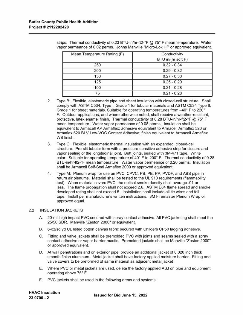
Butler County Public Health Addition Project # 2112202420
HVAC Insulation 23 0700 - 2 Issued for Bid June 15, 2022
strips. Thermal conductivity of 0.23 BTU-in/hr-ft2-°F @ 75° F mean temperature. Water vapor permeance of 0.02 perms. Johns Manville "Micro-Lok HP or approved equivalent.
Mean Temperature Rating (F) Conductivity BTU in/(hr sqft F)
250 0.32 - 0.34200 0.29 - 0.32150 0.27 - 0.30125 0.25 - 0.29100 0.21 - 0.2875 0.21 - 0.28
2. Type B: Flexible, elastomeric pipe and sheet insulation with closed-cell structure. Shall comply with ASTM C534, Type I, Grade 1 for tubular materials and ASTM C534 Type II, Grade 1 for sheet materials. Suitable for operating temperatures from –40° F to 220° F. Outdoor applications, and where otherwise noted, shall receive a weather-resistant, protective, latex enamel finish. Thermal conductivity of 0.28 BTU-in/hr-ft2-°F @ 75° F mean temperature. Water vapor permeance of 0.08 perms. Insulation shall be equivalent to Armacell AP Armaflex; adhesive equivalent to Armacell Armaflex 520 or Armaflex 520 BLV Low-VOC Contact Adhesive; finish equivalent to Armacell Armaflex WB finish.
3. Type C: Flexible, elastomeric thermal insulation with an expanded, closed-cell structure. Pre-slit tubular form with a pressure-sensitive adhesive strip for closure and vapor sealing of the longitudinal joint. Butt joints, sealed with 3M-471 tape. White color. Suitable for operating temperature of 40° F to 200° F. Thermal conductivity of 0.28 BTU-in/hr-ft2-°F mean temperature. Water vapor permeance of 0.20 perms. Insulation shall be Armacell Self-Seal Armaflex 2000 or approved equivalent.
4. Type M: Plenum wrap for use on PVC, CPVC, PB, PE, PP, PVDF, and ABS pipe in return air plenums. Material shall be tested to the UL 910 requirements (flammability test). When material covers PVC, the optical smoke density shall average .01 or less. The flame propagation shall not exceed 2.6. ASTM E84 flame spread and smoke developed rating shall not exceed 5. Installation shall include all tie wires and foil tape. Install per manufacturer's written instructions. 3M Firemaster Plenum Wrap or approved equal.
2.2 INSULATION JACKETS
A. 20-mil high impact PVC secured with spray contact adhesive. All PVC jacketing shall meet the 25/50 SDR. Manville "Zeston 2000" or equivalent.
B. 6-oz/sq yd UL listed cotton canvas fabric secured with Childers CP50 lagging adhesive.
C. Fitting and valve jackets shall be premolded PVC with joints and seams sealed with a spray contact adhesive or vapor barrier mastic. Premolded jackets shall be Manville "Zeston 2000" or approved equivalent.
D. At wall penetrations and on exterior pipe, provide an additional jacket of 0.020 inch thick smooth finish aluminum. Metal jacket shall have factory applied moisture barrier. Fitting and valve covers to be preformed of same material as adjacent metal jacket
E. Where PVC or metal jackets are used, delete the factory applied ASJ on pipe and equipment operating above 75° F.
F. PVC jackets shall be used in the following areas and systems:
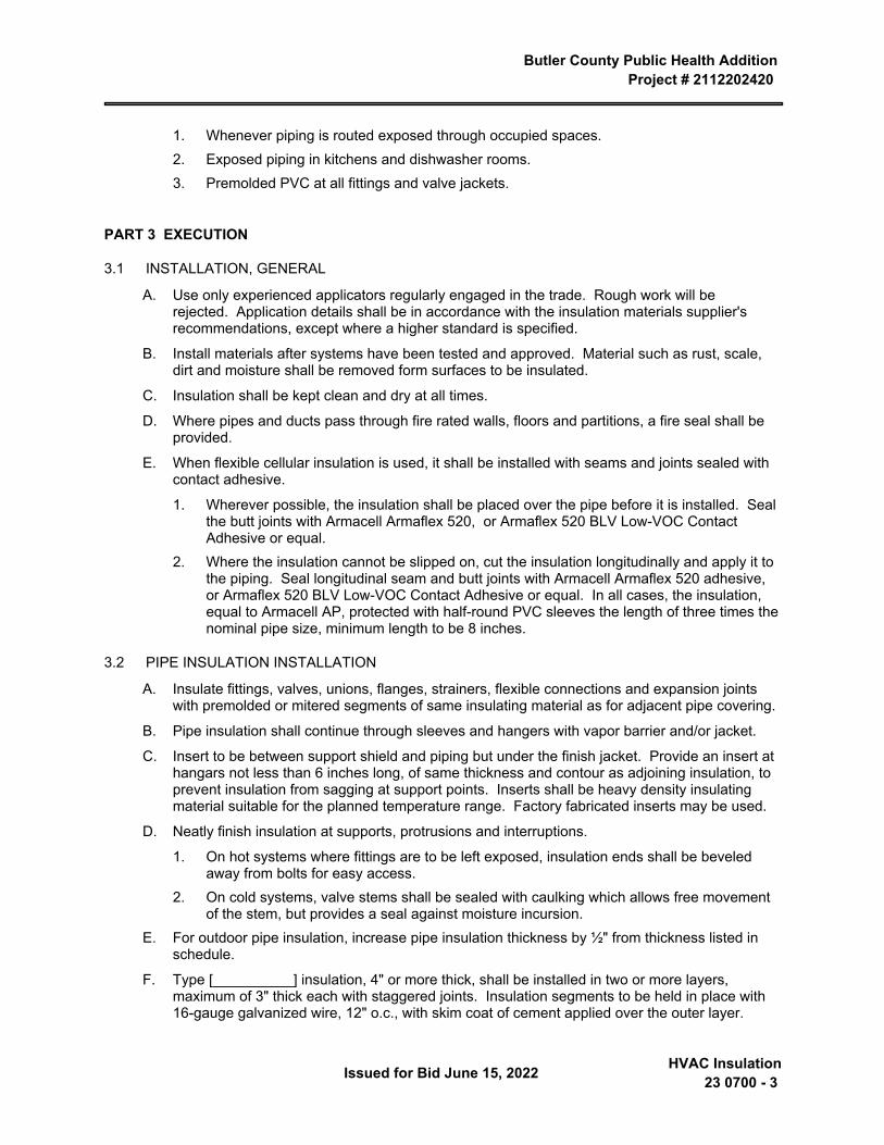
Butler County Public Health Addition Project # 2112202420
Issued for Bid June 15, 2022 HVAC Insulation23 0700 - 3
1. Whenever piping is routed exposed through occupied spaces.2. Exposed piping in kitchens and dishwasher rooms.3. Premolded PVC at all fittings and valve jackets.
PART 3 EXECUTION
3.1 INSTALLATION, GENERAL
A. Use only experienced applicators regularly engaged in the trade. Rough work will be rejected. Application details shall be in accordance with the insulation materials supplier's recommendations, except where a higher standard is specified.
B. Install materials after systems have been tested and approved. Material such as rust, scale, dirt and moisture shall be removed form surfaces to be insulated.
C. Insulation shall be kept clean and dry at all times.
D. Where pipes and ducts pass through fire rated walls, floors and partitions, a fire seal shall be provided.
E. When flexible cellular insulation is used, it shall be installed with seams and joints sealed with contact adhesive.
1. Wherever possible, the insulation shall be placed over the pipe before it is installed. Seal the butt joints with Armacell Armaflex 520, or Armaflex 520 BLV Low-VOC Contact Adhesive or equal.
2. Where the insulation cannot be slipped on, cut the insulation longitudinally and apply it to the piping. Seal longitudinal seam and butt joints with Armacell Armaflex 520 adhesive, or Armaflex 520 BLV Low-VOC Contact Adhesive or equal. In all cases, the insulation, equal to Armacell AP, protected with half-round PVC sleeves the length of three times the nominal pipe size, minimum length to be 8 inches.
3.2 PIPE INSULATION INSTALLATION
A. Insulate fittings, valves, unions, flanges, strainers, flexible connections and expansion joints with premolded or mitered segments of same insulating material as for adjacent pipe covering.
B. Pipe insulation shall continue through sleeves and hangers with vapor barrier and/or jacket.
C. Insert to be between support shield and piping but under the finish jacket. Provide an insert at hangars not less than 6 inches long, of same thickness and contour as adjoining insulation, to prevent insulation from sagging at support points. Inserts shall be heavy density insulating material suitable for the planned temperature range. Factory fabricated inserts may be used.
D. Neatly finish insulation at supports, protrusions and interruptions.
1. On hot systems where fittings are to be left exposed, insulation ends shall be beveled away from bolts for easy access.
2. On cold systems, valve stems shall be sealed with caulking which allows free movement of the stem, but provides a seal against moisture incursion.
E. For outdoor pipe insulation, increase pipe insulation thickness by ½" from thickness listed in schedule.
F. Type [__________] insulation, 4" or more thick, shall be installed in two or more layers, maximum of 3" thick each with staggered joints. Insulation segments to be held in place with 16-gauge galvanized wire, 12" o.c., with skim coat of cement applied over the outer layer.
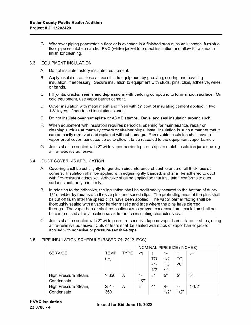
Butler County Public Health Addition Project # 2112202420
HVAC Insulation 23 0700 - 4 Issued for Bid June 15, 2022
G. Wherever piping penetrates a floor or is exposed in a finished area such as kitchens, furnish a floor pipe escutcheon and/or PVC (white) jacket to protect insulation and allow for a smooth finish for cleaning.
3.3 EQUIPMENT INSULATION
A. Do not insulate factory-insulated equipment.
B. Apply insulation as close as possible to equipment by grooving, scoring and beveling insulation, if necessary. Secure insulation to equipment with studs, pins, clips, adhesive, wires or bands.
C. Fill joints, cracks, seams and depressions with bedding compound to form smooth surface. On cold equipment, use vapor barrier cement.
D. Cover insulation with metal mesh and finish with ¼" coat of insulating cement applied in two 1/8" layers, if non-faced insulation is used.
E. Do not insulate over nameplate or ASME stamps. Bevel and seal insulation around such.
F. When equipment with insulation requires periodical opening for maintenance, repair or cleaning such as at manway covers or strainer plugs, install insulation in such a manner that it can be easily removed and replaced without damage. Removable insulation shall have a vapor-proof cover fabricated so as to allow it to be resealed to the equipment vapor barrier.
G. Joints shall be sealed with 2" wide vapor barrier tape or strips to match insulation jacket, using a fire-resistive adhesive.
3.4 DUCT COVERING APPLICATION
A. Covering shall be cut slightly longer than circumference of duct to ensure full thickness at corners. Insulation shall be applied with edges tightly banded, and shall be adhered to duct with fire-resistant adhesive. Adhesive shall be applied so that insulation conforms to duct surfaces uniformly and firmly.
B. In addition to the adhesive, the insulation shall be additionally secured to the bottom of ducts 18" or wider by means of adhesive pins and speed clips. The protruding ends of the pins shall be cut off flush after the speed clips have been applied. The vapor barrier facing shall be thoroughly sealed with a vapor barrier mastic and tape where the pins have pierced through. The vapor barrier shall be continuous to prevent condensation. Insulation shall not be compressed at any location so as to reduce insulating characteristics.
C. Joints shall be sealed with 2" wide pressure-sensitive tape or vapor barrier tape or strips, using a fire-resistive adhesive. Cuts or tears shall be sealed with strips of vapor barrier jacket applied with adhesive or pressure-sensitive tape.
3.5 PIPE INSULATION SCHEDULE (BASED ON 2012 IECC)
NOMINAL PIPE SIZE (INCHES)SERVICE TEMP
( F)TYPE <1 1
TO <1-1/2
1-1/2 TO <4
4 TO <8
8+
High Pressure Steam, Condensate
> 350 A 4-1/2"
5" 5" 5" 5"
High Pressure Steam, Condensate
251 - 350
A 3" 4" 4-1/2"
4-1/2"
4-1/2"
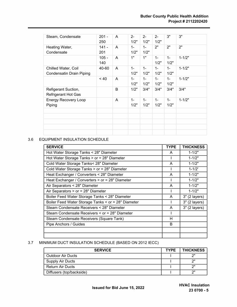
Butler County Public Health Addition Project # 2112202420
Issued for Bid June 15, 2022 HVAC Insulation23 0700 - 5
Steam, Condensate 201 - 250
A 2-1/2"
2-1/2"
2-1/2"
3" 3"
Heating Water, Condensate
141 - 201
A 1-1/2"
1-1/2"
2" 2" 2"
105 - 140
A 1" 1" 1-1/2"
1-1/2"
1-1/2"
Chilled Water, Coil Condensatin Drain Piping
40-60 A 1-1/2"
1-1/2"
1-1/2"
1-1/2"
1-1/2"
< 40 A 1-1/2"
1-1/2"
1-1/2"
1-1/2"
1-1/2"
Refigerant Suction, Refrigerant Hot Gas
B 1/2" 3/4" 3/4" 3/4" 3/4"
Energy Recovery Loop Piping
A 1-1/2"
1-1/2"
1-1/2"
1-1/2"
1-1/2"
3.6 EQUIPMENT INSULATION SCHEDULE
SERVICE TYPE THICKNESSHot Water Storage Tanks < 28" Diameter A 1-1/2"Hot Water Storage Tanks > or = 28" Diameter I 1-1/2"Cold Water Storage Tanks< 28" Diameter A 1-1/2"Cold Water Storage Tanks > or = 28" Diameter I 1-1/2'Heat Exchanger / Converters < 28" Diameter A 1-1/2"Heat Exchanger / Converters > or = 28" Diameter I 1-1/2"Air Separators < 28" Diameter A 1-1/2"Air Separators > or = 28" Diameter I 1-1/2"Boiler Feed Water Storage Tanks < 28" Diameter A 3" (2 layers)Boiler Feed Water Storage Tanks < or = 28" Diameter I 3" (2 layers)Steam Condensate Receivers < 28" Diameter A 3" (2 layers)Steam Condensate Receivers < or = 28" Diameter ISteam Condensate Receivers (Square Tank) HPipe Anchors / Guides B
3.7 MINIMUM DUCT INSULATION SCHEDULE (BASED ON 2012 IECC)
SERVICE TYPE THICKNESSOutdoor Air Ducts I 2"Supply Air Ducts I 2"Return Air Ducts I 2"Diffusers (top/backside) I 2"
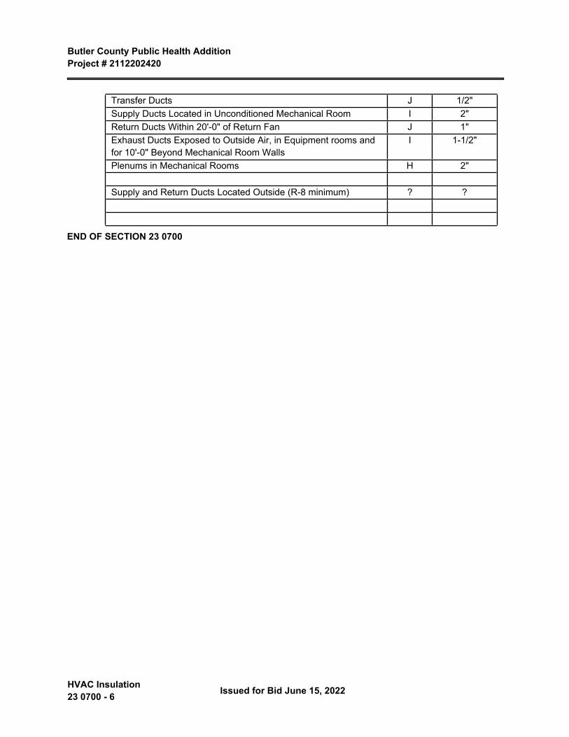
Butler County Public Health Addition Project # 2112202420
HVAC Insulation 23 0700 - 6 Issued for Bid June 15, 2022
Transfer Ducts J 1/2"Supply Ducts Located in Unconditioned Mechanical Room I 2"Return Ducts Within 20'-0" of Return Fan J 1"Exhaust Ducts Exposed to Outside Air, in Equipment rooms and for 10'-0" Beyond Mechanical Room Walls
I 1-1/2"
Plenums in Mechanical Rooms H 2"
Supply and Return Ducts Located Outside (R-8 minimum) ? ?
END OF SECTION 23 0700
Butler County Public Health AdditionProject # 2112202420
Issued for Bid June 15, 2022 Sequence of Operations for
HVAC Controls23 0993 - 1
SECTION 23 0993 SEQUENCE OF OPERATIONS FOR HVAC CONTROLS
PART 1 GENERAL
1.1 SECTION INCLUDES
A. This section defines the manner and method by which controls function. Requirements for each type of control system operation are specified. Equipment, devices, and system components required for control systems are specified in other sections.
B. Sequence of operation for:
1. Heating water zone control.2. Parking garage ventilation systems.3. Radiation and convectors.4. Refrigeration systems.
1.2 RELATED REQUIREMENTS
1.3 SUBMITTALS
A. See Section 01 3000 - Administrative Requirements for submittal procedures.
B. Sequence of Operation Documentation: Submit written sequence of operation for entire HVAC system and each piece of equipment.
1. Preface: 1 or 2 paragraph overview narrative of the system describing its purpose, components and function.
2. State each sequence in small segments and give each segment a unique number for referencing in Functional Test procedures; provide a complete description regardless of the completeness and clarity of the sequences specified in the contract documents.
3. Include at least the following sequences:
a. Start-up.
b. Normal operating mode.
c. Unoccupied mode.
d. Shutdown.
e. Temperature and pressure control, such as setbacks, setups, resets, etc.
f. Interactions and interlocks with other systems.
4. Include initial and recommended values for all adjustable settings, setpoints and parameters that are typically set or adjusted by operating staff; and any other control settings or fixed values, delays, etc. that will be useful during testing and operating the equipment.
5. For packaged controlled equipment, include manufacturer's furnished sequence of operation amplified as required to describe the relationship between the packaged controls and the control system, indicating which points are adjustable control points and which points are only monitored.
Butler County Public Health Addition Project # 2112202420
Sequence of Operations for HVAC Controls 23 0993 - 2
Issued for Bid June 15, 2022
6. Include schedules, if known.C. Control System Diagrams: Submit graphic schematic of the control system showing each
control component and each component controlled, monitored, or enabled.
1. Label with settings, adjustable range of control and limits.2. Include flow diagrams for each control system, graphically depicting control logic.3. Include the system and component layout of all equipment that the control system
monitors, enables or controls, even if the equipment is primarily controlled by packaged or integral controls.
4. Include draft copies of graphic displays indicating mechanical system components, control system components, and controlled function status and value.
5. Include all monitoring, control and virtual points specified in elsewhere.6. Include a key to all abbreviations.
D. Points List: Submit list of all control points indicating at least the following for each point.
1. Name of controlled system.2. Point abbreviation.3. Point description; such as dry bulb temperature, airflow, etc.4. Display unit.5. Control point or setpoint (Yes / No); i.e. a point that controls equipment and can have its
setpoint changed.6. Monitoring point (Yes / No); i.e. a point that does not control or contribute to the control of
equipment but is used for operation, maintenance, or performance verification.7. Intermediate point (Yes / No); i.e. a point whose value is used to make a calculation which
then controls equipment, such as space temperatures that are averaged to a virtual point to control reset.
8. Calculated point (Yes / No); i.e. a “virtual” point generated from calculations of other point values.
E. Designer's Qualification Statement.
F. Project Record Documents: Record actual locations of components and setpoints of controls, including changes to sequences made after submission of shop drawings.
PART 2 PRODUCTS - NOT USED
PART 3 EXECUTION
3.1 HEATING WATER ZONE CONTROL
A. Flow switch in heating pump discharge provides on/off indication.
B. Control heating water supply temperature set at 120 degrees F (49 degrees C) in accordance with outdoor reset schedule by modular boiler gas valve.
C. Flow switch in heating water circuit on no flow conditions closes valve and indicates alarm.
D. On outside temperatures above 65 degrees F (18 degrees C), de-energize heating pumps and suppress alarm.
Butler County Public Health Addition Project # 2112202420
Issued for Bid June 15, 2022 Sequence of Operations for
HVAC Controls23 0993 - 3
3.2 PARKING GARAGE VENTILATION SYSTEMS
A. Carbon Monoxide (CO) detector maintains maximum CO level of 50 ppm by cycling exhaust fan. When CO level exceeds 100 ppm, signal alarm.
3.3 RADIATION AND CONVECTORS
A. Single temperature thermostat set at 55 degrees F (13 degrees C) maintains constant space temperature by modulating two-way control heating valve with spring range of 3 to 7 psig (with spring range of 20 to 48 kPa).
3.4 REFRIGERATION SYSTEMS
A. Maintain constant supply air duct temperature of 55 degrees F (13 degrees C) by cycling refrigeration system and signalling step capacity, minimum of 1 steps.
END OF SECTION

Butler County Public Health AdditionProject # 2112202420
Issued for Bid June 15, 2022 Hydronic Piping23 2113 - 1
SECTION 23 2113 HYDRONIC PIPING
PART 1 GENERAL
1.1 SECTION INCLUDES
A. Hydronic system requirements.
B. Heating water piping, buried.
C. Heating water piping, above grade.
D. Radiant heating piping system.
E. Equipment drains and overflows.
F. Unions, flanges, mechanical couplings, and dielectric connections.
1.2 RELATED REQUIREMENTS
A. Section 22 0516 - Expansion Fittings and Loops for Plumbing Piping.
B. Section 23 0516 - Expansion Fittings and Loops for HVAC Piping.
C. Section 23 0523 - General-Duty Valves for HVAC Piping.
D. Section 23 0548 - Vibration and Seismic Controls for HVAC.
E. Section 23 0553 - Identification for HVAC Piping and Equipment.
F. Section 23 0719 - HVAC Piping Insulation.
G. Section 23 2114 - Hydronic Specialties.
H. Section 23 2500 - HVAC Water Treatment: Pipe cleaning.
I. Section 25 3519 - Integrated Automation Control Valves: Product furnishing.
1.3 REFERENCE STANDARDS
A. ASME BPVC-IX - Boiler and Pressure Vessel Code, Section IX - Qualification Standard for Welding, Brazing, and Fusing Procedures; Welders; Brazers; and Welding, Brazing, and Fusing Operators 2021.
B. ASME B16.3 - Malleable Iron Threaded Fittings: Classes 150 and 300 2021.
C. ASME B16.15 - Cast Copper Alloy Threaded Fittings: Classes 125 and 250 2018.
D. ASME B16.18 - Cast Copper Alloy Solder Joint Pressure Fittings 2021.
E. ASME B16.22 - Wrought Copper and Copper Alloy Solder-Joint Pressure Fittings 2021.
F. ASME B16.34 - Valves — Flanged, Threaded, and Welding End 2020.
G. ASME B31.9 - Building Services Piping 2020.
H. ASTM A53/A53M - Standard Specification for Pipe, Steel, Black and Hot-Dipped, Zinc-Coated, Welded and Seamless 2020.
I. ASTM A106/A106M - Standard Specification for Seamless Carbon Steel Pipe for High-Temperature Service 2019a.
Butler County Public Health Addition Project # 2112202420
Hydronic Piping 23 2113 - 2 Issued for Bid June 15, 2022
J. ASTM A123/A123M - Standard Specification for Zinc (Hot-Dip Galvanized) Coatings on Iron and Steel Products 2017.
K. ASTM A183 - Standard Specification for Carbon Steel Track Bolts and Nuts 2014 (Reapproved 2020).
L. ASTM A234/A234M - Standard Specification for Piping Fittings of Wrought Carbon Steel and Alloy Steel for Moderate and High Temperature Service 2019.
M. ASTM A536 - Standard Specification for Ductile Iron Castings 1984, with Editorial Revision (2019).
N. ASTM B32 - Standard Specification for Solder Metal 2020.
O. ASTM B88 - Standard Specification for Seamless Copper Water Tube 2020.
P. ASTM B88M - Standard Specification for Seamless Copper Water Tube (Metric) 2020.
Q. ASTM D1785 - Standard Specification for Poly(Vinyl Chloride) (PVC) Plastic Pipe, Schedules 40, 80, and 120 2021a.
R. ASTM D2000 - Standard Classification System for Rubber Products in Automotive Applications 2018.
S. ASTM D2235 - Standard Specification for Solvent Cement for Acrylonitrile-Butadiene-Styrene (ABS) Plastic Pipe and Fittings 2021.
T. ASTM D2241 - Standard Specification for Poly(Vinyl Chloride) (PVC) Pressure-Rated Pipe (SDR Series) 2020.
U. ASTM D2466 - Standard Specification for Poly(Vinyl Chloride) (PVC) Plastic Pipe Fittings, Schedule 40 2021.
V. ASTM D2467 - Standard Specification for Poly(Vinyl Chloride) (PVC) Plastic Pipe Fittings, Schedule 80 2020.
W. ASTM D2680 - Standard Specification for Acrylonitrile-Butadiene-Styrene (ABS) and Poly(Vinyl Chloride) (PVC) Composite Sewer Piping 2020.
X. ASTM D2855 - Standard Practice for the Two-Step (Primer and Solvent Cement) Method of Joining Poly (Vinyl Chloride) (PVC) or Chlorinated Poly (Vinyl Chloride) (CPVC) Pipe and Piping Components with Tapered Sockets 2020.
Y. ASTM F876 - Standard Specification for Crosslinked Polyethylene (PEX) Tubing 2022.
Z. ASTM F877 - Standard Specification for Crosslinked Polyethylene (PEX) Hot- and Cold-Water Distribution Systems 2020.
AA. ASTM F1476 - Standard Specification for Performance of Gasketed Mechanical Couplings for Use in Piping Applications 2007 (Reapproved 2019).
BB. AWS A5.8M/A5.8 - Specification for Filler Metals for Brazing and Braze Welding 2019.
CC. AWWA C105/A21.5 - Polyethylene Encasement for Ductile-Iron Pipe Systems 2018.
DD. AWWA C110/A21.10 - Ductile-Iron and Gray-Iron Fittings 2021.
EE. AWWA C111/A21.11 - Rubber-Gasket Joints for Ductile-Iron Pressure Pipe and Fittings 2017.
FF. AWWA C151/A21.51 - Ductile-Iron Pipe, Centrifugally Cast 2017, with Errata (2018).
GG. AWWA C606 - Grooved and Shouldered Joints 2015.
HH. DIN EN 4726 - Warm Water Surface Heating Systems and Radiator Connecting Systems - Plastics Piping Systems and Multilayer Piping Systems 2017.
Butler County Public Health Addition Project # 2112202420
Issued for Bid June 15, 2022 Hydronic Piping23 2113 - 3
1.4 ADMINISTRATIVE REQUIREMENTS
A. Preinstallation Meeting: Conduct a preinstallation meeting one week prior to the start of the work of this section; require attendance by all affected installers.
B. Sequencing: Ensure that utility connections are achieved in an orderly and expeditious manner.
1.5 QUALITY ASSURANCE
A. Provide all grooved joint couplings, fittings, valves, specialties, and grooving tools from a single manufacturer.
B. Welder Qualifications: Certify in accordance with ASME BPVC-IX.
1. Provide certificate of compliance from authority having jurisdiction, indicating approval of welders.
1.6 DELIVERY, STORAGE, AND HANDLING
A. Accept valves on site in shipping containers with labeling in place. Inspect for damage.
B. Provide temporary protective coating on cast iron and steel valves.
C. Provide temporary end caps and closures on piping and fittings. Maintain in place until installation.
D. Protect piping systems from entry of foreign materials by temporary covers, completing sections of the work, and isolating parts of completed system.
1.7 FIELD CONDITIONS
A. Do not install underground piping when bedding is wet or frozen.
PART 2 PRODUCTS
2.1 HYDRONIC SYSTEM REQUIREMENTS
A. Comply with ASME B31.9 and applicable federal, state, and local regulations.
B. Piping: Provide piping, fittings, hangers, and supports as required, as indicated, and as follows:
1. Where more than one piping system material is specified, provide joining fittings that are compatible with piping materials and ensure that the integrity of the system is not jeopardized.
2. Use non-conducting dielectric connections whenever jointing dissimilar metals.3. Grooved mechanical joints may be used in accessible locations only.
a. Accessible locations include those exposed on interior of building, in pipe chases, and in mechanical rooms, aboveground outdoors, and as approved by Engineer.
b. Grooved mechanical connections and joints comply with AWWA C606.
1) Ductile Iron: Comply with ASTM A536, Grade 65-45-12.2) Steel: Comply with ASTM A106/A106M, Grade B or ASTM A53/A53M.
c. Use rigid joints unless otherwise indicated.

Butler County Public Health Addition Project # 2112202420
Hydronic Piping 23 2113 - 4 Issued for Bid June 15, 2022
4. Provide pipe hangers and supports in accordance with ASME B31.9 or MSS SP-58 unless indicated otherwise.
C. Pipe-to-Valve and Pipe-to-Equipment Connections: Use flanges, unions, or grooved couplings to allow disconnection of components for servicing; do not use direct welded, soldered, or threaded connections.
D. Valves: Provide valves where indicated:
1. Provide drain valves where indicated, and if not indicated, provide at least at main shut-off, low points of piping, bases of vertical risers, and at equipment. Use 3/4 inch (20 mm) gate valves with cap; pipe to nearest floor drain.
2. On discharge of condenser water pumps, use spring-loaded check valves.3. Isolate equipment using butterfly valves with lug end flanges or grooved mechanical
couplings.4. For throttling, bypass, or manual flow control services, use globe, ball, or butterfly valves.5. In heating water systems, butterfly valves may be used interchangeably with gate and
globe valves.6. For shut-off and to isolate parts of systems or vertical risers, use gate, ball, or butterfly
valves.7. For throttling service, use plug cocks. Use non-lubricated plug cocks only when shut-off
or isolating valves are also provided.E. Welding Materials and Procedures: Comply with ASME BPVC-IX.
2.2 HEATING WATER PIPING, BURIED
A. Steel Pipe: ASTM A53/A53M, Schedule 40, black, with AWWA C105/A21.5 polyethylene jacket, or double layer, half-lapped polyethylene tape.
B. Copper Tube: ASTM B88 (ASTM B88M), Type K (A), annealed.
1. Fittings: ASME B16.22, wrought copper.2. Joints: Braze, AWS A5.8M/A5.8 BCuP copper/silver alloy.3. Casing: Closed glass cell insulation.
2.3 HEATING WATER PIPING, ABOVE GRADE
A. Steel Pipe: ASTM A53/A53M, Schedule 40, black, using one of the following joint types:
1. Welded Joints: ASTM A234/A234M, wrought steel welding type fittings; AWS D1.1/D1.1M welded.
2. Threaded Joints: ASME B16.3, malleable iron fittings.3. Grooved Joints: AWWA C606 grooved pipe, fittings of same material, and mechanical
couplings.B. Copper Tube: ASTM B88 (ASTM B88M), Type K (A), drawn, using one of the following joint
types:
1. Solder Joints: ASME B16.18 cast brass/bronze or ASME B16.22 solder wrought copper fittings.
a. Solder: ASTM B32 lead-free solder, HB alloy (95-5 tin-antimony) or tin and silver.
b. Braze: AWS A5.8M/A5.8 BCuP copper/silver alloy.
Butler County Public Health Addition Project # 2112202420
Issued for Bid June 15, 2022 Hydronic Piping23 2113 - 5
2. Grooved Joints: AWWA C606 grooved tube, fittings of same material, and copper-tube-dimension mechanical couplings.
3. Tee Connections: Mechanically extracted collars with notched and dimpled branch tube.4. Mechanical Press Sealed Fittings: Double pressed type complying with ASME B16.22,
utilizing EPDM, nontoxic synthetic rubber sealing elements.
a. Manufacturers:
1) Apollo Valves; [______]: www.apollovalves.com/#sle.2) Grinnell Products; [______]: www.grinnell.com/#sle.3) Viega LLC; [______]: www.viega.us/#sle.
2.4 RADIANT HEATING AND COOLING PIPING
A. Copper Tube: ASTM B88 (ASTM B88M), Type K (A) annealed.
1. Fittings: ASME B16.22, wrought copper.2. Joints: Braze, AWS A5.8M/A5.8 BCuP copper/silver alloy.
B. Polyethylene Pipe: ASTM F876 or ASTM F877, cross-linked polyethylene, 100 psig (690 kPa) operating pressure at 180 degrees F (82 degrees C).
1. Fittings: Brass and copper.2. Joints: Mechanical compression fittings.
C. Composite Polyethylene Pipe: Aluminum tube laminated between two layers of high density polyethylene.
1. Operating Pressure:
a. 125 psig (861 kPa) at maximum 140 degrees F (60 degrees C).
2. Fittings: Brass flared compression.3. Joints: Fittings adapt to copper tubing or copper tube fittings, threaded pipe and fittings,
and copper compression fittings.D. Hose: Composite hose with nitrile liner, braided fiber reinforcing, neoprene cover, 150 psig
(1034 kPa) operating pressure at 205 degrees F (96 degrees C).
1. Fittings: Copper.2. Joints: Nipple with stainless steel clamp.
2.5 EQUIPMENT DRAINS AND OVERFLOWS
A. Steel Pipe: ASTM A53/A53M, Schedule 40 galvanized; using one of the following joint types:
1. Threaded Joints: Galvanized cast iron, or ASME B16.3 malleable iron fittings.2. Grooved Joints: AWWA C606 grooved pipe, fittings of same material, and mechanical
couplings.B. Copper Tube: ASTM B88 (ASTM B88M), Type K (A), drawn; using one of the following joint
types:
1. Solder Joints: ASME B16.18 cast brass/bronze or ASME B16.22 solder wrought copper fittings; ASTM B32 lead-free solder, HB alloy (95-5 tin-antimony) or tin and silver.
2. Grooved Joints: AWWA C606 grooved pipe, fittings of same material, and mechanical couplings.
Butler County Public Health Addition Project # 2112202420
Hydronic Piping 23 2113 - 6 Issued for Bid June 15, 2022
C. PVC Pipe: ASTM D1785, Schedule 40, or ASTM D2241, SDR 21 or 26.
1. Fittings: ASTM D2466 or D2467, PVC.2. Joints: Solvent welded in accordance with ASTM D2855.
D. ABS Pipe: ASTM D2680.
1. Fittings: Compatible with piping material.2. Joints: Solvent welded with ASTM D2235 cement.
2.6 UNIONS, FLANGES, MECHANICAL COUPLINGS, AND DIELECTRIC CONNECTIONS
A. Unions for Pipe 2 Inches (50 mm) and Less:
1. Ferrous Piping: 150 psig (1034 kPa) malleable iron, threaded.2. Copper Pipe: Bronze, soldered joints.
B. Flanges for Pipe 2 Inches (50 mm) and Greater:
C. Mechanical Couplings for Grooved and Shouldered Joints: Two or more curved housing segments with continuous key to engage pipe groove, circular C-profile gasket, and bolts to secure and compress gasket.
1. Dimensions and Testing: In accordance with AWWA C606.2. Mechanical Couplings: Comply with ASTM F1476.3. Housing Material: Ductile iron, galvanized complying with ASTM A536.4. Gasket Material: Nitrile rubber suitable for operating temperature range from minus 20
degrees F to 180 degrees F (minus 29 degrees C to 82 degrees C).5. Bolts and Nuts: Hot dipped galvanized or zinc-electroplated steel.6. When pipe is field grooved, provide coupling manufacturer's grooving tools.7. Manufacturers:
a. Anvil International
b. Apollo Valves
c. Grinnell Products
d. Shurjoint Piping Products, Inc.
e. Victaulic Company
D. Dielectric Connections:
1. Waterways:
a. Water impervious insulation barrier capable of limiting galvanic current to 1 percent of short circuit current in a corresponding bimetallic joint.
b. Dry insulation barrier able to withstand 600-volt breakdown test.
c. Construct of galvanized steel with threaded end connections to match connecting piping.
d. Suitable for the required operating pressures and temperatures.
2.7 FLEXIBLE CONNECTORS
Butler County Public Health Addition Project # 2112202420
Issued for Bid June 15, 2022 Hydronic Piping23 2113 - 7
A. 4in and below shall be fabricated of a corrugated bronze inner tube with braided wire stainless steel or bronze outer jacket. Tubes to be welded to pipe ends, threaded through 2in size, flanged for sizes 2-1/2 in. through 4in
2.8 PIPE ESUTCHEONS
A. Manufacturer
1. Chicago Specialty2. Producers Specialty3. Sanitary-Dash
B. Provide pipe esutcheons with inside diameter closely fitting pipe outside diameter, or outside of pipe insulation where be is insulated. Outside diameter of esutcheon to completely cover pipe penetration hole in floors, walls, or ceilings; and pipe sleeve extensions, if any. Furnish pipe escutcheons with chrome finish for occupied areas, prime paint finish for unoccupied areas.
C. Moist Areas: For waterproof floors, and areas where water condensation can be expected to accumulate, provide cast brass or sheet brass escutcheons, solid of split hinged.
D. Dry Areas: Provide sheet steel escutcheons, solid or split hinged
PART 3 EXECUTION
3.1 PREPARATION
A. Ream pipe and tube ends. Remove burrs. Bevel plain end ferrous pipe.
B. Prepare pipe for grooved mechanical joints as required by coupling manufacturer.
C. Remove scale and dirt on inside and outside before assembly.
D. Prepare piping connections to equipment using jointing system specified.
E. Keep open ends of pipe free from scale and dirt. Protect open ends with temporary plugs or caps.
F. After completion, fill, clean, and treat systems. Refer to Section 23 2500 for additional requirements.
3.2 INSTALLATION
A. Install in accordance with manufacturer's instructions.
B. Install heating water, glycol, chilled water, condenser water, and engine exhaust piping to ASME B31.9 requirements.
C. PVC Pipe: Make solvent-welded joints in accordance with ASTM D2855.
D. Route piping in orderly manner, parallel to building structure, and maintain gradient.
E. Install piping to conserve building space and to avoid interference with use of space.
F. Group piping whenever practical at common elevations.
G. Sleeve pipe passing through partitions, walls, and floors.
H. Install firestopping to preserve fire resistance rating of partitions and other elements, using materials and methods specified [__________].
I. Slope piping and arrange to drain at low points.
Butler County Public Health Addition Project # 2112202420
Hydronic Piping 23 2113 - 8 Issued for Bid June 15, 2022
J. Install piping to allow for expansion and contraction without stressing pipe, joints, or connected equipment. Refer to Section 22 0516.
K. Grooved Joints:
1. Install in accordance with the manufacturer's latest published installation instructions.2. Gaskets to be suitable for the intended service, molded, and produced by the coupling
manufacturer.L. Inserts:
1. Provide inserts for placement in concrete formwork.2. Provide inserts for suspending hangers from reinforced concrete slabs and sides of
reinforced concrete beams.3. Where concrete slabs form finished ceiling, locate inserts flush with slab surface.
END OF SECTION
Butler County Public Health AdditionProject # 2112202420
Issued for Bid June 15, 2022 Hydronic Pumps23 2123 - 1
SECTION 23 2123 HYDRONIC PUMPS
PART 1 GENERAL
1.1 SECTION INCLUDES
A. In-line circulators.
B. Dual drive pumping system.
1.2 REFERENCE STANDARDS
A. UL 778 - Standard for Motor-Operated Water Pumps Current Edition, Including All Revisions.
1.3 SUBMITTALS
A. See Section 01 3000 - Administrative Requirements, for submittal procedures.
1.4 QUALITY ASSURANCE
PART 2 PRODUCTS
2.1 HVAC PUMPS - GENERAL
A. Provide pumps that operate at specified system fluid temperatures without vapor binding and cavitation, are non-overloading in parallel or individual operation, and operate within 25 percent of midpoint of published maximum efficiency curve.
B. Products Requiring Electrical Connection: Listed and classified by UL or testing agency acceptable to Authority Having Jurisdiction as suitable for the purpose specified and indicated.
2.2 IN-LINE CIRCULATORS
2.3 DUAL DRIVE PUMPING SYSTEM
PART 3 EXECUTION
3.1 PREPARATION
A. Lay out exact location for concrete pump bases, and furnish to General Contractor a dimensional drawing showing base sizes and locations.
3.2 INSTALLATION
A. Install in accordance with manufacturer's instructions.
B. Provide access space around pumps for service. Provide no less than minimum space recommended by manufacturer.
END OF SECTION

Butler County Public Health AdditionProject # 2112202420
Issued for Bid June 15, 2022 HVAC Ducts and Casings23 3100 - 1
SECTION 23 3100 HVAC DUCTS AND CASINGS
PART 1 GENERAL
1.1 SECTION INCLUDES
A. Metal ductwork.
B. Nonmetal ductwork.
C. Casing and plenums.
D. Buried ductwork.
E. Kitchen hood ductwork.
F. Duct cleaning.
G. Gas/flue vent
H. Ductwork leak testing
1.2 RELATED REQUIREMENTS
A. Section 23 0130.51 - HVAC Air-Distribution System Cleaning: Cleaning ducts after completion of installation.
B. Section 23 0593 - Testing, Adjusting, and Balancing for HVAC.
C. Section 23 0713 - Duct Insulation: External insulation and duct liner.
D. Section 23 3300 - Air Duct Accessories.
E. Section 23 3600 - Air Terminal Units.
F. Section 23 3700 - Air Outlets and Inlets.
1.3 REFERENCE STANDARDS
A. ASTM A653/A653M - Standard Specification for Steel Sheet, Zinc-Coated (Galvanized) or Zinc-Iron Alloy-Coated (Galvannealed) by the Hot-Dip Process 2020.
B. ASTM A666 - Standard Specification for Annealed or Cold-Worked Austenitic Stainless Steel Sheet, Strip, Plate, and Flat Bar 2015.
C. ASTM A1008/A1008M - Standard Specification for Steel, Sheet, Cold-Rolled, Carbon, Structural, High-Strength Low-Alloy, High-Strength Low-Alloy with Improved Formability, Required Hardness, Solution Hardened, and Bake Hardenable 2021a.
D. ASTM B209 - Standard Specification for Aluminum and Aluminum-Alloy Sheet and Plate 2014.
E. ASTM B209M - Standard Specification for Aluminum and Aluminum-Alloy Sheet and Plate (Metric) 2014.
F. ASTM C14 - Standard Specification for Nonreinforced Concrete Sewer, Storm Drain, and Culvert Pipe 2020.
G. ASTM E84 - Standard Test Method for Surface Burning Characteristics of Building Materials 2021a.
H. NFPA 90A - Standard for the Installation of Air-Conditioning and Ventilating Systems 2021.
Butler County Public Health Addition Project # 2112202420
HVAC Ducts and Casings 23 3100 - 2 Issued for Bid June 15, 2022
I. NFPA 90B - Standard for the Installation of Warm Air Heating and Air-Conditioning Systems 2021.
J. NFPA 96 - Standard for Ventilation Control and Fire Protection of Commercial Cooking Operations 2021.
K. SMACNA (DCS) - HVAC Duct Construction Standards Metal and Flexible 2021.
L. SMACNA (FGD) - Fibrous Glass Duct Construction Standards 2021.
M. SMACNA (KVS) - Kitchen Ventilation Systems and Food Service Equipment Fabrication and Installation Guidelines 2001.
N. SMACNA (LEAK) - HVAC Air Duct Leakage Test Manual 2012.
O. UL 181 - Standard for Factory-Made Air Ducts and Air Connectors current edition, including all revisions.
1.4 SUBMITTALS
A. See Section 01 3000 - Administrative Requirements, for submittal procedures.
B. Product Data: Provide data for duct materials.
C. Shop Drawings: Submit ductwork shop drawings for entire facility, to scale, double line, indicating duct sizes, locations, elevations, fittings, equipment, accessories, structural clearances, etc. Do not install ductwork prior to approval of shop drawings by Engineer.
1.5 QUALITY ASSURANCE
A. Manufacturer Qualifications: Company specializing in manufacturing the type of products specified in this section, with minimum three years of documented experience, and approved by manufacturer.
1.6 FIELD CONDITIONS
A. Do not install duct sealants when temperatures are less than those recommended by sealant manufacturers.
B. Maintain temperatures within acceptable range during and after installation of duct sealants.
PART 2 PRODUCTS
2.1 DUCT ASSEMBLIES
A. Regulatory Requirements: Construct ductwork to comply with NFPA 90A, NFPA 90B, and NFPA 96 standards.
B. Ducts: Galvanized steel, unless otherwise indicated.
C. Air ducts shall be constructed as follows:
1. Supply and return duct in Mechanical Rooms 6 inch w.g. 2. Supply and return duct in shaft 4 inch w.g. 3. Constant volume supply duct 2 inch w.g. 4. Return duct 2 inch w.g. 5. OA ducts and plenums 2 inch w.g.
Butler County Public Health Addition Project # 2112202420
Issued for Bid June 15, 2022 HVAC Ducts and Casings23 3100 - 3
6. Miscellaneous duct (exhaust, transfer grille, etc.) 2 inch w.g. D. Outside Air Intake: 1 inch w.g. pressure class, galvanized steel.
E. Combustion Air: 1 inch w.g. pressure class, galvanized steel.
2.2 MATERIALS
A. Galvanized Steel for Ducts: Hot-dipped galvanized steel sheet, ASTM A653/A653M FS Type B, with G60/Z180 coating.
B. Un-Galvanized Steel for Ducts: ASTM A1008/A1008M Designation CS (commercial steel), cold-rolled.
C. Aluminum for Ducts: ASTM B209 (ASTM B209M); aluminum sheet, alloy 3003-H14. Aluminum Connectors and Bar Stock: Alloy 6061-T651 or of equivalent strength.
D. Stainless Steel for Ducts: ASTM A666, Type 304.
E. Concrete Pipe for Buried Ducts: ASTM C14 ASTM C14M Class 1 Nonreinforced, ASTM C14 ASTM C14M Class 2 Nonreinforced, or ASTM C14 ASTM C14M Class 3 Nonreinforced hub and spigot concrete sewer pipe; ASTM C443 ASTM C443M joints with standard rubber gaskets.
F. PVC Coating for Steel Ducts: 4 mils (0.1 mm) polyvinyl chloride plastic on both sides.
G. Joint Sealers and Sealants: Non-hardening, water resistant, mildew and mold resistant.
1. Duct sealant shall be installed per SMACNA Class A-all transverse joints, longitudinal seams and duct wall penetrations.
2. Type: Heavy mastic or liquid used alone or with tape, suitable for joint configuration and compatible with substrates, and recommended by manufacturer for pressure class of ducts.
3. Surface Burning Characteristics: Flame spread index of zero and smoke developed index of zero, when tested in accordance with ASTM E84.
4. For Use With Flexible Ducts: UL labeled.5. Manufacturers:
a. Carlisle HVAC Products; Hardcast Iron-Grip 601 Water Based Duct Sealant:
b. Design Polymerics; DP 1010 Water Based Smooth Duct Sealant, Zero VOC, Premium Quality
c. Ductmate Industries, Inc, a DMI Company
H. Hanger Rod: ASTM A36/A36M; steel, galvanized; threaded both ends, threaded one end, or continuously threaded.
I. Hanger Fasteners: Attach hangers to structure using appropriate fasteners, as follows:
1. Concrete Wedge Expansion Anchors: Complying with ICC-ES AC193.2. Masonry Wedge Expansion Anchors: Complying with ICC-ES AC01.3. Concrete Screw Type Anchors: Complying with ICC-ES AC193.4. Masonry Screw Type Anchors: Complying with ICC-ES AC106.5. Concrete Adhesive Type Anchors: Complying with ICC-ES AC308.6. Other Types: As required.7. Manufacturers:
Butler County Public Health Addition Project # 2112202420
HVAC Ducts and Casings 23 3100 - 4 Issued for Bid June 15, 2022
a. Powers Fasteners, Inc; [_____]: www.powers.com/#sle.
2.3 DUCTWORK FABRICATION
A. Fabricate and support in accordance with SMACNA (DCS) and as indicated.
B. Provide duct material, gages, reinforcing, and sealing for operating pressures indicated.
C. Construct T's, bends, and elbows with radius of not less than1.0 times width of duct on centerline. Where not possible and where rectangular elbows must be used, provide air foil single thickness turning vanes. Provide trailing edge extension for elbows in series.
D. Provide turning vanes of perforated metal with glass fiber insulation when acoustical lining is indicated.
E. Increase duct sizes gradually, not exceeding 15 degrees divergence wherever possible; maximum 30 degrees divergence upstream of equipment and 45 degrees convergence downstream.
F. Fabricate continuously welded round and oval duct fittings in accordance with SMACNA (DCS).
2.4 MANUFACTURED DUCTWORK AND FITTINGS
A. Double Wall Insulated Round Ducts: Round spiral lockseam duct with galvanized steel outer wall, perforated galvanized steel inner wall; fitting with solid inner wall.
1. Manufacture in accordance with SMACNA (DCS).2. Insulation:
a. Thickness: 1 inch
b. Material: Fiberglass.
3. Manufacturers:
a. MKT Metal Manufacturing
b. United Mcgill
c. Semco
d. Eastern Sheet Metal
B. Spiral Ducts: Round spiral lockseam duct with galvanized steel outer wall.
1. Manufacture in accordance with SMACNA (DCS).2. Manufacturers:
a. United McGill
b. Semco
c. EHG, a DMI Company
d. GSI, a DMI Company
e. Linx Industries, Inc, a DMI Company
f. MKT Metal Manufacturing
C. Round Ducts: Round lockseam duct with galvanized steel outer wall.
Butler County Public Health Addition Project # 2112202420
Issued for Bid June 15, 2022 HVAC Ducts and Casings23 3100 - 5
1. Manufacture in accordance with SMACNA (DCS).2. Manufacturers:
a. United Mcgill
b. Semco
c. EHG, a DMI Company
d. Linx Industries, Inc, a DMI Company
e. MKT Metal Manufacturing
D. Flexible Ducts: UL 181, Class 1, aluminum laminate and polyester film with latex adhesive supported by helically wound spring steel wire.
1. Pressure Rating: 10 Inches w.g. positive and 1 inch w.g. negative.2. Maximum Velocity: 4000 fpm.3. Temperature Range: Minus 20 degrees F to 210 degrees F..4. Manufacturers:
a. JP Lamborn Co
b. Thermaflex
c. Flexmaster
d. Hart & Cooley, Inc.
E. Antimicrobial Flexible Ducts: UL 181, Class 1, aluminum laminate and polyester film with latex adhesive supported by helically wound spring steel wire.
1. Pressure Rating: 10 inches w.g. positive and 1 inch w.g. negative.2. Maximum Velocity: 4000 fpm.3. Temperature Range: Minus 20 degrees F to 210 degrees F.4. Manufacturers:
a. JP Lamborn Co
b. Thermaflex
c. Flexmaster
F. Transverse Duct Connection System: SMACNA "E" rated rigidly class connection, interlocking angle and duct edge connection system with sealant, gasket, cleats, and corner clips in accordance with SMACNA (DCS).
1. Manufacturers:
a. Carlisle HVAC Products
b. Ductmate Industries, Inc, a DMI Company
c. Elgen Manufacturing
d. MKT Metal Manufacturing
G. Round Duct Connection System: Interlocking duct connection system in accordance with SMACNA (DCS).
Butler County Public Health Addition Project # 2112202420
HVAC Ducts and Casings 23 3100 - 6 Issued for Bid June 15, 2022
1. Manufacturers:
a. Ductmate Industries, Inc, a DMI Company
2.5 CASINGS
A. Fabricate casings in accordance with SMACNA (DCS) and construct for operating pressures indicated.
B. Mount floor mounted casings on 4 inch high concrete curbs. At floor, rivet panels on 8 inch centers to angles. Where floors are acoustically insulated, provide liner of galvanized 8 inch expanded metal mesh supported at 12 inch centers, turned up 12 inch at sides with sheet metal shields.
C. Reinforce door frames with steel angles tied to horizontal and vertical plenum supporting angles. Install hinged access doors where indicated or required for access to equipment for cleaning and inspection.
1. Provide clear wire glass observation ports, minimum 6x6 size.D. Fabricate acoustic casings with reinforcing turned inward. Provide 16 gage sheet steel back
facing and 22 gage perforated sheet steel front facing with 3/32 inch diameter holes on 5/32 inch centers. Construct panels 3 inches thick packed with 4.5 lb/cu-ft minimum glass fiber insulation media, on inverted channels of 16 gage sheet steel.
2.6 KITCHEN HOOD EXHAUST DUCTWORK
A. Fabricate in accordance with ductwork manufacturer's installation instructions, SMACNA (DCS), SMACNA (KVS), and NFPA 96.
PART 3 EXECUTION
3.1 INSTALLATION
A. Install, support, and seal ducts in accordance with SMACNA (DCS).
B. Install in accordance with manufacturer's instructions.
C. During construction provide temporary closures of metal or taped polyethylene on open ductwork to prevent construction dust from entering ductwork system.
D. Flexible Ducts: Connect to metal ducts with adhesive.
E. Kitchen Hood Exhaust: Provide residue traps at base of vertical risers with provisions for clean out.
F. Duct sizes indicated are inside clear dimensions. For lined ducts, maintain sizes inside lining.
G. Locate ducts with sufficient space around equipment to allow normal operating and maintenance activities.
H. Use crimp joints with or without bead for joining round duct sizes 8 inch and smaller with crimp in direction of air flow.
I. Use double nuts and lock washers on threaded rod supports.
J. Connect diffusers or light troffer boots to low pressure ducts directly or with 5 feet maximum length of flexible duct held in place with strap or clamp.
K. At exterior wall louvers, seal duct to louver frame and install blank-out panels.
Butler County Public Health Addition Project # 2112202420
Issued for Bid June 15, 2022 HVAC Ducts and Casings23 3100 - 7
3.2 CLEANING
A. See Section 01 7419 - Construction Waste Management and Disposal, for additional requirements.
END OF SECTION

Butler County Public Health AdditionProject # 2112202420
Issued for Bid June 15, 2022 Air Duct Accessories23 3300 - 1
SECTION 23 3300 AIR DUCT ACCESSORIES
PART 1 GENERAL
1.1 SUMMARY
A. This Section includes the following:
1. Backdraft dampers.2. Volume dampers.3. Motorized control dampers.4. Fire dampers.5. Ceiling fire dampers.6. Smoke dampers.7. Combination fire and smoke dampers.8. Duct Silencers9. Turning vanes.10. Duct-mounting access doors.11. Flexible connectors.12. Flexible ducts.
1.2 SUBMITTALS
A. Product Data: For the following:
1. Backdraft dampers.2. Volume dampers.3. Fire dampers.4. Ceiling fire dampers.5. Smoke dampers.6. Combination fire and smoke dampers.7. Duct Silencers.8. Turning vanes.9. Duct-mounting access doors.10. Flexible connectors.11. Flexible ducts.
B. Shop Drawings:
1. Product Data: Submit manufacturer's technical product data and installation instructions for metal ductwork materials and products.
1.3 QUALITY ASSURANCE
A. Codes and Standards
Butler County Public Health Addition Project # 2112202420
Air Duct Accessories 23 3300 - 2 Issued for Bid June 15, 2022
1. Comply with NFPA 90A, "Installation of Air Conditioning and Ventilating Systems," and NFPA 90B, "Installation of Warm Air Heating and Air Conditioning Systems."
2. Fire, Smoke, and Combination Dampers:
a. Constructed and tested in accordance with UL Safety Standard 555 and 555S, for 1 1/2 hour fire protection rating, with 165oF fusible link, and shall bear UL label.
3. Duct Silencers
a. Fabrication and installation shall comply with AMCA, ADC Airflow Test Codes, NFPA 255, UL No. 723
4. Ducts, plenums, apparatus casings, metal gauges, reinforcing, methods of supporting and hanging, and other sheet metal work as called for shall meet all functional criteria defined in the SMACNA "HVAC Duct Construction Standards Metal and Flexible" 2005, 3rd Edition. This shall be subsequently referred to as the SMACNA Manual. All ductwork must comply with all local, state and federal code requirements.
5. Comply with applicable requirements of NFPA 91.
PART 2 PRODUCTS
2.1 BACKDRAFT DAMPERS
A. Furnish and install a heavy-duty counterbalanced backdraft damper with steel frame and steel airfoil type 18 gauge steel blades. Blades shall have EPDM seals and jamb seals and be spaced a maximum width of 7" with ¾ inch diameter plated steel axles. The bearings shall be ball bearings pressed into the frame. Damper shall be Ruskin CBS8 or approved equal.
2.2 VOLUME DAMPERS
A. Manual Volume Dampers: Fabricated of same material as ducts, two metal gauges heavier than duct and hemmed 1" all around, mounted on 3/8" square rod with saw slot position indicated. Pivot bearings, elocking position regulator, Young Regulator Co., Series 443.
1. Where positioning regulator is not accessible, provide coupling and extension rod with regulator for ceiling wall or floor installation, as required. Young Series 301 and 315 for ceiling, Series 270-302 for walls.
2.3 FIRE DAMPERS
2.4 SMOKE AND COMBINATION FIRE AND SMOKE DAMPERS
2.5 DUCT SILENCERS
2.6 TURNING VANES
A. Manufacturers:
1. Aero Dyne; Ductmate; Anemostat; Barber Coleman; Duro Dyne; or Hart & Cooley.B. Provide single thickness streamline type, except provide turning vanes with trailing edge at
elbows which change dimensions or at consecutive elbows.
C. Provide manufactured turning vanes and vane runners, fabricated from the same material as the duct, and constructed in accordance with SMACNA "HVAC Duct Construction
Butler County Public Health Addition Project # 2112202420
Issued for Bid June 15, 2022 Air Duct Accessories23 3300 - 3
Standards". Tab spacing shall be SMACNA standard. Rail systems with non-standard tab spacings shall not be accepted. All tabs shall be used, do not skip tabs. Mounting rails shall have friction insert tabs which align the vanes automatically. Vanes shall be subjected to tensile loading and be capable of supporting 250 lbs. when fastened per the manufacturer's instructions.
2.7 DUCT-MOUNTING ACCESS DOORS
A. General:
1. Shall be of same material as ducts in which they are installed, fabricated of two thicknesses of not less than 22 gauge, with 1" thick rigid glass fiber filler. Provide sheet metal frame, airtight gasket and two cam latches. Access doors and panels shall be 2 inches smaller than duct width and square for ducts 18” wide and larger, maximum size shall be 24" x 24" unless noted otherwise. For ducts less than 18” wide, access doors and panels shall be 2” smaller than duct width and 18” long. Pre-manufactured doors shall be hinged and shall be of adequate size to allow easy access to hardware which needs to be maintained.
2.8 FLEXIBLE DUCT CONNECTIONS
A. Manufacturers:
1. Ventfabric, Inc., Ventglass, Duro Dyne, Ductmate or American/Elgin.B. General:
1. 30 ounce woven glass fiber, double neoprene coated, fire retardant, waterproof and airtight, suitable for temperatures to 200o F, UL approved.
2.9 FLEXIBLE DUCTS
A. Manufacturers:
1. Flexible duct shall be by Thermaflex, Semco, Wiremold, or Engineer approved equal.B. General:
1. Acceptable in supply ductwork only where shown (not allowed in exposed occupied areas). Flexible duct shall include wire, core, insulation, and vapor barrier and the composite assembly shall meet requirements of NFPA-90A and UL181 and shall be UL listed for flame spread rating of not more than 25 and smoke developed rated of not more than 50.
C. Minimum length of flexible duct shall be 3 feet.
D. Maximum length of flexible duct shall be 8 feet.
E. Flexible duct shall have a minimum R-value of 4.2.
F. Flexible duct shall have a maximum vapor transmission rating of .1 perms.
G. Flexible duct shall be rated for operating temperatures between -20 and 250 degrees.
H. All flexible duct shall be connected to metal fittings with stainless steel bands equal to snaplock. The use of duct tape to secure the core is not acceptable.
I. Flexible duct shall have an operating positive pressure rating of 16" wg for nominal sizes 4 thru 10 inch and 10" wg for nominal sizes 12 thru 16 inch, and a negative pressure rating of 2" wg for sizes 4 thru 16 inches. Duct shall be rated for a velocity of 6,000 feet per minute. Duct shall be equal to Thermaflex M-KE.
Butler County Public Health Addition Project # 2112202420
Air Duct Accessories 23 3300 - 4 Issued for Bid June 15, 2022
2.10 QUADRANT LOCKS
A. Provide for each damper, quadrant lock device on one end of shaft; and end bearing plate on other end for damper lengths over 12".
B. Provide extended quadrant locks and end extended bearing plates for externally insulated ductwork.
PART 2 EXECUTION
3.1 APPLICATION AND INSTALLATION
A. Install manual volume dampers in all supply, return and exhaust duct systems as required for controlling air volumes to trunk ducts, branch ducts, outlets and inlets. Contractor shall install a complete system of dampers as required for balancing air systems.
B. Coordinate duct installations with installation of accessories, equipment, controls and other associated work of the ductwork system.
C. Install access panels for inspection and servicing of duct mounted equipment; reheat coils, sound attenuators, and smoke and fire dampers.
D. Install flexible connections in ducts at connections to plenums, apparatus casings, fan housings, roof top units, air handling units, exhaust fans and other equipment which could transmit vibrations to the duct systems. Crimp into duct flanges for attachment to duct and equipment. Make airtight joint. Provide adequate joint flexibility to allow for thermal axial, transverse, and torsional movement, and also capable of absorbing vibration of connected equipment.
E. Install turning vanes in all square or rectangular 90° elbows in supply, return, and exhaust air systems.
F. Installation of Flexible Ducts: Flexible Ducts are to be installed only where indicated on Drawings.
1. Maximum length of flexible duct is 8'-0" OAL.2. Minimum length of flexible duct is 3'-0" OAL.3. Square to round transition gages to comply with SMACNA rectangular duct (minimum 24
ga.).4. Flexible duct must meet UL 181 and be installed per SMACNA using a clamp for securing
duct to collar and a supplemental clamp for securing the insulation and vapor barrier.5. Support flexible ductwork with minimum 2" wide sheet metal bands, secured to structure
with ductwork support materials. Maximum spacing shall be 4 feet on center.6. The flexible duct shall be installed with a minimum centerline radius equal to 1.5 times the
diameter of the duct.7. When connecting flexible duct to diffusers, the duct shall be installed with a minimum of
6" straight flex at the diffuser.G. Installation of Fire Dampers:
H. Installation of Smoke or Combination Fire and Smoke Dampers:
I. Installation of Duct Silencers

Butler County Public Health Addition Project # 2112202420
Issued for Bid June 15, 2022 Air Duct Accessories23 3300 - 5
END OF SECTION 23 3300

Butler County Public Health AdditionProject # 2112202420
Issued for Bid June 15, 2022 Fans23 3416 - 1
SECTION 23 3416 FANS
PART 1 GENERAL
1.1 SECTION INCLUDES
A. The extent of work is shown on drawings and in schedules and by requirements of this section, and is hereby defined to include, but not by way of limitation:
1. Inline centrifugal fans2. Propeller fans3. Up-blast axial fans4. Ceiling exhaust fans5. Bathroom exhaust fans6. Fan accessories7. Motors and drives
1.2 CODES AND STANDARDS
A. Installer: A firm with at least 3 years of successful fan installation experience.
B. AMCA Standards: Comply with air movement and control association standards as applicable to testing and rating fans, including but not limited to, AMCA 99, 210, 211, 261, 300, 301. Provide fans that bear the AMCA Certified Ratings Seal for sound and air performance.
C. UL Compliance: Provide fan and components which are UL listed and labeled.
D. SMACNA Standards: Comply with applicable portions of SMACNA duct construction standards.
E. Grease hood exhaust fans shall be UL listed for grease removal (UL762)
1.3 PRODUCT DELIVERY, STORAGE AND HANDLING
A. Deliver products with factory-installed shipping skids and lifting lugs; pack components in factory-fabricated protective framing.
B. Handle products carefully to avoid damage to components, enclosures and finish. Do not install damaged components; replace and return damaged components to manufacturer for repairs or replacement.
C. Store products in clean dry place and protect from weather and construction traffic.
1.4 SUBMITTALS
A. Shop Drawings: Shop drawings shall indicate assembly, unit dimensions, weight loading, required clearances, construction details, and field connection details.
B. Product Data: Product data shall indicate performance data relative to the information scheduled on the drawings. In addition, provide dimensions, weights, capacities, ratings, fan performance, motor electrical characteristics, and gauges and finishes of materials.
C. Provide fan curves with specified operating point clearly plotted.
D. Submit sound power levels for both fan inlet and outlet and radiation at rated capacity.

Butler County Public Health Addition Project # 2112202420
Fans 23 3416 - 2 Issued for Bid June 15, 2022
E. Submit electrical requirements for power supply wiring including wiring diagrams for interlock and control wiring clearly indicating factory installed and field installed wiring.
F. Submit manufacturer’s installation instructions.
1.5 ENVIRONMENTAL REQUIREMENTS
A. Do not operate units for any purpose, temporary or permanent, until ductwork is clean, filters are in place, bearings lubricated, and fan has been test run under observation.
1.6 EXTRA MATERIALS
A. Supply two sets of belts for each belt driven fan.
PART 2 PRODUCTS
2.1 MANUFACTURERS
A. Subject to compliance with requirements, provide products by one of the following, or engineer approved equivalent:
1. Greenheck2. Penn barry3. Trane4. Cook5. Twin City Fan6. Carnes7. Jenn Fan8. Aerovent9. Acme10. Buffalo Forge, Division of Howden Fan11. Howden Fan12. Sun Air13. Gaylord14. General Electric
2.2 GENERAL
A. Provide fans of type, sizes, ratings and capacities as indicated on drawings and in schedules.
2.3 TUBULAR OR IN-LINE CENTRIFUGAL FANS
A. Fan housing shall be constructed of continuously welded heavy gauge steelnot less than 14 gauge steel. Housing and bearing support shall be constructed of structural steel members to prevent vibration and rigidly support shaft and bearings.
B. Wheel
1. Fan wheel shall be non-overloading backward inclined or airfoil, Class I construction.
Butler County Public Health Addition Project # 2112202420
Issued for Bid June 15, 2022 Fans23 3416 - 3
2. Fan wheel shall be statically and dynamically balanced and factory run tested as an assembled fan.
C. Bearings shall be heavy duty, grease lubricated, self-aligning ball bearing or roller pillow block type, selected for a minimum of 200,000 hour life. Lubrication lines shall be extended to exterior of fan housing.
D. Motors shall also be high efficiency in accordance with section 23 0500, inverter rated, high power factor type motors for use with A-C adjustable speed drive. Provide Century E plus motors or equivalent 460V, 3 phase, 60 HZ.
E. Shaft shall be precision ground and polished steel.
F. Motor shall be NEMA standard, normal torqued, 55 degree C rise, ODP of horsepower rating and electrical characteristics as scheduled. Motor shall have service factor not less than 1.15.
G. Belt driven fans shall be constructed with motor base plate welded to exterior of fan housing, with motor mounted on adjustable slide rail. Provide weatherproof cover for motor and drive. Provide OSHA approved belt guard.
H. Accessories
1. Provide galvanized steel welded grid inlet and outlet screen.2. Provide 1” threaded drain connector with plug to drain fan housing.3. Provide hinged access door in housing for maintenance.4. Provide flexible duct connector at inlet and outlet for connection to duct system.5. Provide mounting brackets for installation as indicated on drawings and in schedules.6. Fixed Inlet Vanes: Steel construction with fixed cantilevered inlet guide vanes welded to inlet
bell.7. Discharge Dampers: Parallel blade heavy duty steel damper assembly with blades
constructed of two plates formed around and welded to shaft, channel frame.8. Factory finish before assembly to manufacturers standards.9. Vibration Isolation: Refer to Section 23 0548 for vibration isolation requirements.
2.4 PROPELLER FANS
A. Propeller: Shaped steel or steel reinforced aluminum blade with heavy hubs, statically and dynamically balanced, keyed and locked to shaft, directly connected to motoror provided with V-belt drive.
B. Motors and drives shall be scheduled on the Drawings. On direct drive units, motors shall be resiliently mounted in basket type guards of heavy-duty steel in a concentric ring pattern. On belt drive units, motors shall be mounted on an adjustable motor base. Motor to be equipped with an adjustable pitch sheave.
C. Frame: One piece, square steel with die formed venturi orifice, mounting flanges and supports, with baked enamel finish.
D. Accessories
1. Backdraft damper: Multiple blade with offset hinge pin, blades linked.2. Outlet damper: Multiple blade with offset hinge pin, blades linked, line voltage motor drive,
power open, spring return.3. Safety Screens: Expanded galvanized metal over inlet, motor, and drive [and outlet]; to
comply with OSHA regulations.
Butler County Public Health Addition Project # 2112202420
Fans 23 3416 - 4 Issued for Bid June 15, 2022
4. Hood: Weathershield, to exclude rain and snow.5. Controller: Solid-state speed controller.
2.5 ROOF AND WALL EXHAUSTERS
A. Roof Mounted Fans
1. Centrifugal or Axial Fan, V-belt or direct driven as scheduled with spun aluminum housing, resilient mounted motor, 1/2 inch mesh bird screen, square base to suit roof curb, continuous curb gaskets, plate bolts and screws.
2. Roof Curb: 12 inch higself-flashing curb with continuously welded seams, built-in cant strip, 1 inch insulation and curb bottom, interior baffle and insulated with acoustic insulation and curb bottom, hinged curb adapter, factory installed wood nailer strip.
3. Disconnect Switch: Factory wired non-fusible in housing for thermal overload protected motor and wall mounted multiple speed switch.
4. Motorized Damper: Motorized opposed blade damper interlocked with fan.5. V-belt Drive: Cast iron or steel sheaves, dynamically balanced, bored to fit shafts and keyed,
variable and adjustable pitch motor sheave selected so required rpm is obtained with sheaves set at mid-position, fan shaft with self aligning pre-lubricated ball bearings.
B. Wall Exhausters
1. Centrifugal or Axial fan, V-belt or direct driven as scheduled, with spun aluminum housing, motor, 1/2 inch mesh bird screen, cadmium plated bolts and screws.
2. Disconnect Switch: Factory wired non-fusible in housing for thermal overload protected motor and wall mounted multiple speed switch.
3. Motorized Damper: Motorized opposed blade damper interlocked with fan.4. V-belt Drive: Cast iron or steel sheaves, dynamically balanced, bored to fit shafts and keyed,
variable and adjustable pitch motor sheave selected so requiring rpm is obtained with sheaves set at mid-position, fan shaft with self aligning pre-lubricated ball bearings.
2.6 GREASE HOOD EXHAUST FAN
A. Centrifugal Exhaust Fan: Provide centrifugal exhaust fan of type, size and capacity as scheduled, and as specified herein.
B. Type: Centrifugal fan, belt-driven as scheduled. Provide aluminum weatherproof housings as scheduled. Provide capacitor-start, induction-run type motor for belt driven fans.
C. Belt-driven Units: Provide ball bearing motor mounted on adjustable base, with adjustable sheaves. Provide lubricating tubes from fan bearings outside of fan housing.
D. Belt-Driven Fans shall be provided with adjustable sheaves selected at mid-range to allow speed adjustment up or down equally. Horsepower of motor shall be capable of not exceeding FLA with sheave adjustment to highest RPM range.
E. Electrical: Provide factory wired non-fusible disconnect switch external to air stream thermal overload protection in fan motor.
F. Provide removable bird guard.
G. Provide means for inspecting, cleaning, and servicing the exhaust fan.
H. Provide an insulating heat baffle to
I. Dampers shall not be used in grease hood fan.
Butler County Public Health Addition Project # 2112202420
Issued for Bid June 15, 2022 Fans23 3416 - 5
2.7 CABINET AND CEILING EXHAUST FANS
A. Centrifugal Fan: V-belt or Direct driven as scheduled, with galvanized steel housing lined with 1/2 inch acoustic insulation, resilient mounted motor, gravity backdraft damper in discharge.
B. Disconnect Switch: Factory wired non-fusible in housing for thermal overload protected motor and wall mounted multiple speed switch.
C. Grille for Ceiling Fan: Molded white plastic grille or aluminum grille with baked white enamel finish.
D. V-belt Drive: Cast iron or steel sheaves, dynamically balanced, bored to fit shafts and keyed, variable and adjustable pitch motor sheave selected so required rpm is obtained with sheaves set at mid-position, fan shaft with self aligning pre-lubricated ball bearings.
2.8 BATHROOM EXHAUST FANS
A. Assembly: Multi-blade, forward curved wheel in steel housing for between stud mounting.
B. Motor: Resiliently mounted, direct driven fan and motor, with two-speed plug-in type motor with permanently lubricated bearings.
C. Intake Grille: One piece aluminum.
PART 3 EXECUTION
3.1 INSPECTION
A. Installer shall examine areas and conditions under which fans are to be installed, and notify Contractor in writing of conditions detrimental to proper completion of the work. Do not proceed with the work until unsatisfactory conditions have been corrected in a manner acceptable to Installer.
3.2 INSTALLATION OF FANS
A. Install fans where shown in accordance with equipment manufacturer’s written instructions, recognized industry practices, and in accordance with National Electrical Code, to ensure compliance with requirements and serve intended purposes.
B. Coordinate with other work, including ductwork, roof decking, vibration isolation, and electrical work, as necessary to interface installation of fans with other work.
C. Temporary Closure: Upon completion of installation, provide protective covering on fan ductwork connection openings to prevent entrance of dust and debris into equipment.
D. Install vibration isolators and flexible electrical leads to properly isolate the fan vibration from the structure.
E. Provide all direct drive fans with a fan speed controller for balancing.
F. Install horizontal thrust restraints on fans operating at over 2 inch static pressure.
G. Duct Connections: Provide ductwork, accessories, and flexible connections as indicated.
H. Provide adjustable sheaves required for final air balance.
I. Provide safety screen where inlet or outlet is exposed.
J. Provide backdraft dampers on discharge of exhaust fans and as indicated.
K. Provide access to adjustable blade axial fan wheels for varying blade angle setting. Adjust blades for varying range of volume and pressure.
Butler County Public Health Addition Project # 2112202420
Fans 23 3416 - 6 Issued for Bid June 15, 2022
L. Provide floor mounted axial fans with reinforced legs. Provide ceiling suspended units with support brackets bolted to casing flange.
M. Prevention of grease accumulation: Grease hood fans shall be constructed and installed without dips or traps that cause accumulation of grease.
N. Do not operate fans in normal operation until ductwork is clean, filters are in place, bearings are lubricated, and fan has been test run under observation.
O. Secure roof and wall exhausters with cadmium plated steel lag screws to roof curb.
P. Extend ducts to roof and wall exhausters into roof curb. Counterflash duct to roof opening.
3.3 ELECTRICAL CONNECTIONS
A. Insure that the fan is wired properly for proper fan rotationand proper interface with associated thermostat, variable speed controller and outdoor air damper.
B. Provide positive electrical motor grounding.
3.4 TESTING
A. After installation of fans has been completed, test each fan to demonstrate proper operation of unit at performance requirements specified, including, but not limited to, proper rotation of impeller. When possible, field correct malfunctioning units, then retest to demonstrate compliance. Replace units which cannot be satisfactorily corrected at no additional cost to owner.
3.5 MANUFACTURER’S START-UP SERVICES
A. Manufacturer shall furnish a factory trained service engineer without additional charge to start the unit(s).
3.6 WARRANTY
A. Provide a full parts warranty for one year from start-up or 18 months from shipment, whichever occurs first.
END OF SECTION 23 3416

Butler County Public Health AdditionProject # 2112202420
Issued for Bid June 15, 2022 CARBON MONOXIDE (CO/NO2)
DETECTION SYSTEM23 3519 - 1
SECTION 23 3519 CARBON MONOXIDE (CO/NO2) DETECTION SYSTEM
PART 1 GENERAL
1.1 SECTION INCLUDES
A. Mechanical contractor is responsible for providing equipment, material, devices, labor, wiring, conduit and supervision necessary to furnish and install a complete Carbon Monoxide (CO) and Nitrogen Dioxide (NO2) Detection System as required by the Drawings and this section.
B. Factory start-up and calibration required from Manufacturer’s representative.
1.2 SUBMITTALS:
A. Submit complete Product, Performance, and Installation Data with wiring diagrams.
1.3 CODES AND REGULATIONS
A. Detection system design, equipment, materials, devices, and installation shall conform to NFPA Codes and Requirements, Governmental Bodies and Standards Bodies as listed below.
1. Certified to UL and CSA Requirements2. Applicable local building codes3. International Mechanical Code
1.4 TESTS AND CERTIFICATION
A. Contractor shall verify unit is manufactured to UL 1244 or UL 508 label and CSA 22.2. Monitor must be manufactured within an ISO 9002 production environment.
B. Tests shall be conducted in the presence of the authority having jurisdiction as required. The Contractor shall have available at the site, a copy of the prescribed test. Contractor shall give ample notice as to time for conducting tests.
C. Should any component of the system fail the prescribed test, Contractor shall replace such component as required to pass the test.
D. Upon completion of installation and test, Contractor shall prepare Contractor's Material and Test Certificate. Certificate shall be signed by the Contractor. Contractor shall furnish copies of the signed Certificate to authorities with jurisdiction, Owner, Insurance Rating Bureau, and Architect/Engineer as required.
E. The system shall be completely installed, tested, certified, and maintained by a Company normally and primarily engaged in the installation of this type of system. The installing company shall have been engaged in this business for a minimum of five (5) years.
1.5 WIRING
A. Coordinate power and controls wiring with the general and electrical contractor. See CO/NO2/VOC detail on plans for responsibility of work effort.
1.6 INSTRUCTIONS
Butler County Public Health Addition Project # 2112202420
CARBON MONOXIDE (CO/NO2) DETECTION SYSTEM 23 3519 - 2
Issued for Bid June 15, 2022
A. The Owner shall be thoroughly instructed in the operation and maintenance of this system for a maximum period of four (4) hours, or as necessary for the Owner's complete understanding of the operation and routine maintenance.
B. The Owner shall sign a certification indicating that he received the instructions, that they were complete and satisfactory, and that the Owner understands the operation and maintenance of the system.
PART 2 PRODUCTS
2.1 EQUIPMENT
A. The CO/NO2/VOC monitoring system shall be by:
1. Critical Environment Technologies (Basis of Design: FCS controller and LPT sensors)2. Vulcain Alarm Inc.3. Engineer approved equal.
B. The CO/NO2/VOC monitoring system shall consist of remote sensors, a single point control module, Relay Module. Remote sensor locations and control cabinet location shall be as indicated on the drawings.
1. Electrochemical sensor with +/- 3% accuracy for CO.2. Detection Range CO: 0-200 PPM3. Detection Range NO2: 0-10 PPM4. Provide Controller and sensors.5. Provide Remote Relay Expansion Module for control of fans. Reference sequence of
control on plans.6. Provide Alarm (horn/strobe).
PART 3 EXECUTION
3.1 INSTALLATION
A. General: Comply with applicable codes and these Specifications. Install the CO Detection System in accordance with manufacturer's written instructions, and in accordance with recognized industry standards and practices to assure Owner that the system serves the intended purpose.
B. CO and NO2 detectors to be mounted 48-72" AFF where indicated on drawings.
C. See connection/control detail on the plans for sequence of operation. This contractor shall be responsible for all conduit, wiring and control devices necessary for a functioning, variable-flow ventilation system.
3.2 ADJUST AND CLEAN
A. System shall be cleaned and adjusted after installation.
B. This Contractor shall certify to Owner that the system is operating properly and will serve the purpose intended.
Butler County Public Health Addition Project # 2112202420
Issued for Bid June 15, 2022 CARBON MONOXIDE (CO/NO2)
DETECTION SYSTEM23 3519 - 3
3.3 FIELD QUALITY CONTROL
A. Contractor shall include in his base bid the cost of Factory start-up and Calibration of sensors required from Manufacturer’s representative.
END OF SECTION


Butler County Public Health AdditionProject # 2112202420
Issued for Bid June 15, 2022 Air Outlets and Inlets23 3700 - 1
SECTION 23 3700 AIR OUTLETS AND INLETS
PART 1 GENERAL
1.1 SECTION INCLUDES
A. Diffusers:
1. Square and rectangular ceiling diffusersB. Supply registers and grilles
C. Exhaust and return registers and grilles
D. Louvers:
1. Combination louvers.E. Goosenecks.
1.2 REFERENCE STANDARDS
A. AHRI 880 (I-P) - Performance Rating of Air Terminals 2017.
B. AMCA 500-L - Laboratory Methods of Testing Louvers for Rating 2012 (Reapproved 2015).
C. AMCA 511 - Certified Ratings Program Product Rating Manual for Air Control Devices 2021.
D. AMCA 550 - Test Method for High Velocity Wind Driven Rain Resistant Louvers 2015, with Editorial Revision (2018).
E. ASHRAE Std 70 - Method of Testing the Performance of Air Outlets and Inlets 2006 (Reaffirmed 2021).
F. ASHRAE Std 130 - Laboratory Methods of Testing Air Terminal Units 2016.
G. ASTM B221 - Standard Specification for Aluminum and Aluminum-Alloy Extruded Bars, Rods, Wire, Profiles, and Tubes 2021.
H. ASTM B221M - Standard Specification for Aluminum and Aluminum-Alloy Extruded Bars, Rods, Wire, Profiles, and Tubes (Metric) 2021.
I. ASTM C635/C635M - Standard Specification for the Manufacture, Performance, and Testing of Metal Suspension Systems for Acoustical Tile and Lay-in Panel Ceilings 2017.
J. ASTM C636/C636M - Standard Practice for Installation of Metal Ceiling Suspension Systems for Acoustical Tile and Lay-In Panels 2019.
K. ASTM E84 - Standard Test Method for Surface Burning Characteristics of Building Materials 2021a.
L. FLA (PAD) - Florida Building Code Online - Product Approval Directory Current Edition.
M. ISO 14644-1 - Cleanrooms and associated controlled environments - Part 1: Classification of air cleanliness by particle concentration 2015.
N. Miami (APD) - Approved Products Directory; Miami-Dade County Current Edition.
O. UL 2518 - Standard for Safety Air Dispersion Systems Current Edition, Including All Revisions.
P. UL 723 - Standard for Test for Surface Burning Characteristics of Building Materials Current Edition, Including All Revisions.
Butler County Public Health Addition Project # 2112202420
Air Outlets and Inlets 23 3700 - 2 Issued for Bid June 15, 2022
Q. NFPA 90A - Standard for the Installation of Air-Conditioning and Ventilating Systems 2021.
R. NFPA 90B - Standard for the Installation of Warm Air Heating and Air-Conditioning Systems 2021.
S. SMACNA (ASMM) - Architectural Sheet Metal Manual 2012.
T. SMACNA (DCS) - HVAC Duct Construction Standards Metal and Flexible 2021.
1.3 SUBMITTALS
A. See Section 01 3000 - Administrative Requirements for submittal procedures.
B. Product Data: Provide data for equipment required for this project. Review outlets and inlets as to size, finish, and type of mounting prior to submission. Submit schedule of outlets and inlets showing type, size, location, application, and noise level.
C. Project Record Documents: Record actual locations of air outlets and inlets.
1.4 QUALITY ASSURANCE
A. Test and rate air outlet and inlet performance in accordance with ASHRAE Std 70.
B. Test and rate louver performance in accordance with AMCA 500-L.
C. Manufacturer Qualifications: Company specializing in manufacturing the type of products specified in this section, with minimum three years of documented experience.
PART 2 PRODUCTS
2.1 MANUFACTURERS
A. Diffusers, Registers, and Grilles
1. Anemostat2. Carnes, a division of Carnes Company Inc3. Hart & Cooley, Inc4. Krueger-HVAC5. Metalaire, a brand of Metal Industries Inc.6. Nailor7. Price Industries8. Raymon-Donco9. Titus, a brand of Air Distribution Technologies10. Tuttle and Bailey
2.2 SQUARE AND RECTANGULAR CEILING DIFFUSERS
A. The square cone diffuser shall be supplied to deliver a 360 degree radial, horizontal airflow pattern. The cones and backpan shall be one-piece die-formed with smooth, aerodynamically designed surfaces and no corner joints. This contoured design shall protect the ceiling and help to prevent smudging and streaking. Diffusers shall consist of a seamless, one-piece, precision formed backpan that incorporates a round inlet collar of sufficient length for connecting rigid or flexible duct. An inner cone assembly shall consist of 3 or 4 cones which drop below the ceiling plane to assure optimal VAV air diffusion performance.
Butler County Public Health Addition Project # 2112202420
Issued for Bid June 15, 2022 Air Outlets and Inlets23 3700 - 3
B. Type: Provide square, adjustable pattern, stamped, multi-core diffuser to discharge air in one way, two way, three way, and four way pattern with sectorizing baffles where indicated.
C. The finish shall be an anodic acrylic paint, baked at 315 degrees F for 30 minutes. The pencil hardness must be HB to H.
D. The manufacturer shall provide published performance data for the diffuser. The diffuser shall be tested in accordance with ANSI/ASHRAE Standard 70-2006.
E. Connections: Round.
F. Fabrication: Aluminum with baked enamel finish.
G. Color: As selected by Engineer from manufacturer's standard range.
H. Accessories: Opposed blade damper when indicated on the plans and schedules.
2.3 PERFORATED FACE CEILING DIFFUSERS
A. Type: Perforated face with fully adjustable pattern and removable face.
B. Frame: Surface mount type In plaster ceilings, provide plaster frame and ceiling frame.
C. Fabrication:Aluminum with aluminum frame and baked enamel finish.
D. Accessories: Opposed blade damper when indicated on the plans and schedules.
2.4 SUPPLY REGISTERS/GRILLES
A. Supply grilles shall be double deflection of the sizes, capacities, and blade spacing as shown on the plans and schedules. All supply grilles shall be constructed with a 1¼-inch wide steel border having a minimum thickness of 20-gauge. Corners shall be assembled with full penetration resistance welds with a reinforcing steel patch for extra strength. Screw holes shall be countersunk for a neat appearance. Blades shall be constructed of heavy duty aluminum and shall be contoured to a specifically designed airfoil cross-section to meet published performance data. Hollow blades are not acceptable. Blades must be solid. Blades shall extend completely through the side frame on each side to ensure stability throughout the complete cfm operating range of the grille. Blades shall be individually adjustable without loosening or rattling and shall be securely held in place with tension wire.
B. Type: Streamlined and individually adjustable curved blades to discharge air along face of grille, two-way deflection.
C. The finish shall be an anodic acrylic paint, baked at 315 degrees F for 30 minutes. The pencil hardness must be HB to H.
D. The manufacturer shall provide published performance data for the grille. The grille shall be tested in accordance with ANSI/ASHRAE Standard 70-2006.
E. Frame: 1-1/4 inch (32 mm) margin with countersunk screw mounting and gasket.
F. Construction: Made of aluminum extrusions with factory enamel finish.
G. Color: As indicated on drawings.
H. Accessories: Opposed blade damper where indicated on the plans and schedules.
2.5 EXHAUST AND RETURN REGISTERS/GRILLES
A. Return grilles shall be of the sizes, capacities, and blade spacing as shown on the plans and schedules. Construction shall be of extruded aluminum with a 1¼-inch wide border on all sides and shall be interlocked at the four corners and mechanically staked to form a rigid frame. Minimum border thickness shall be 0.040 to 0.050 inch. Screw holes shall be countersunk for a
Butler County Public Health Addition Project # 2112202420
Air Outlets and Inlets 23 3700 - 4 Issued for Bid June 15, 2022
neat appearance. Blades shall be contoured to a specifically designed and tested cross-section to meet published performance data. Blades shall be firmly held in place by mullions from behind the grille and fixed in place by crimping or welding. Blade shall have a fixed deflection angle of 45°.
B. Type: Streamlined blades, 1/2 inch maximum spacing, with blades set at 45 degrees, horizontal face.
C. The finish shall be an anodic acrylic paint, baked at 315 degrees F for 30 minutes. The pencil hardness must be HB to H.
D. The manufacturer shall provide published performance data for the grille. The grille shall be tested in accordance with ANSI/ASHRAE Standard 70-2006.
E. Accessories: Opposed blade damper where indcated on the plans and schedules
2.6 LOUVERS
A. Manufacturers:
1. NCA, a brand of Metal Industries Inc2. Ruskin Company3. Greenheck4. American Louver Company5. American Warming and Ventilating Company6. Airolite7. Nailor8. Price9. Carnes
B. Stationary drainable louver type with drain gutters in each blade and head with downspouts in jambs and mullions with all welded construction. Hidden vertical supports to allow continuous line appearance up to 120 inches (3,048 mm). Steeply angled integral sill.
C. Fabrication: Extruded aluminum, Alloy 6063-T6
D. Water Penetration: Maximum of 0.01 ounces per square foot of free area at an air flow of 873 feet per minute free area velocity when tested for 15 minutes. Based on testing 48 inch x 48 inch size unit in accordance with AMCA 500.
E. Finish to be Kynar 500 fluoropolymer coating (70% PVDF) in color as selected by architect. 20 year warranty on finish colors.
F. Bird Screen: 1/2-inch mesh, 16-gauge aluminum, secured in removable aluminum frame..
G. Mounting: Furnish with extended sill flashing
2.7 COMBINATION LOUVERS
A. Manufacturers:
1. Ruskin Company; [______]: www.ruskin.com/#sle.B. Damper-combined, drainable louver:
C. Size: As indicated on the drawings.
D. Material: Extruded galvanized steel.
Butler County Public Health Addition Project # 2112202420
Issued for Bid June 15, 2022 Air Outlets and Inlets23 3700 - 5
E. Paint Finish and Color: As indicated on the drawings.
F. Rust Inhibitor Coating: Standard.
G. Sleeve or Flange: Factory-mounted standard.
H. Duct Transition Fitting: Round.
I. Custom Features: Include architectural finish.
J. Insulation: Water-resistant sound absorbing material.
K. Mounting: Furnish with interior flat flange for installation.
2.8 GOOSENECKS
A. Fabricate in accordance with of minimum 18 gauge, 0.0598 inch (1.21 mm) galvanized steel.
B. Mount on minimum 12 inch (300 mm) high curb base where size exceeds 9 by 9 inch (230 by 230 mm).
PART 3 EXECUTION
3.1 INSTALLATION
A. Install in accordance with manufacturer's instructions.
B. Comply with SMACNA (ASMM) for flashing/counter-flashing of roof penetrations and supports for roof curbs and roof mounted equipment.
C. Secure louver rigid with concealed fasteners of non-corrosive metals to suit materials as being encountered.
D. Coordinate installation method with application of exterior materials and mechanical work.
E. Set and tie into flashings to ensure diversion of moisture to exterior.
F. Install removable bird screens.
G. Caulk around louvers to form seal with surrounding building materials. Verify proper drainage through weep holes following caulking.
H. Check location of outlets and inlets and make necessary adjustments in position to comply with architectural features, symmetry, and lighting arrangement.
I. Provide balancing dampers on duct take-off to diffusers, and grilles and registers, despite whether dampers are specified as part of the diffuser, or grille and register assembly.
J. Caulk around louvers to form seal with surrounding building materials. Verify proper drainage through weep holes following caulking.
K. Provide transitions as required for connections to ductwork, including square to round.
L. Coordinate wall grilles and registers with thin-line type fire dampers in fire rated walls
M. Install diffusers, registers, and grilles level and plumb.
END OF SECTION

Butler County Public Health AdditionProject # 2112202420
Issued for Bid June 15, 2022 Condensing Boilers23 5216 - 1
SECTION 23 5216 CONDENSING BOILERS
PART 1 GENERAL
1.1 SECTION INCLUDES
A. Manufactured units.
B. Boiler construction.
C. Boiler trim.
D. Fuel burning system.
E. Factory installed controls.
1.2 RELATED SECTIONS
A. Section 03 3000 - Cast-in-Place Concrete.
B. Section 23 0913 - Instrumentation and Control Devices for HVAC.
C. Section 23 2114 - Hydronic Specialties.
D. Section 23 2123 - Hydronic Pumps.
E. Section 23 2500 - HVAC Water Treatment.
F. Section 23 5100 - Breechings, Chimneys, and Stacks.
G. Section 26 0583 - Wiring Connections: Electrical characteristics and wiring connections.
1.3 REFERENCES
A. AHRI Directory of Certified Product Performance - Air-Conditioning, Heating, and Refrigeration Institute (AHRI) Current Edition.
B. AHRI 1500 - Performance Rating of Commercial Space Heating Boilers 2015.
C. ANSI Z21.13 - American National Standard for Gas-Fired Low Pressure Steam and Hot Water Boilers 2017, with Errata (2018).
D. ASHRAE Std 90.1 I-P - Energy Standard for Buildings Except Low-Rise Residential Buildings Most Recent Edition Adopted by Authority Having Jurisdiction, Including All Applicable Amendments and Supplements.
E. ASHRAE Std 103 - Methods of Testing for Annual Fuel Utilization Efficiency of Residential Central Furnaces and Boilers 2022.
F. ASME BPVC-IV - Boiler and Pressure Vessel Code, Section IV - Rules for Construction of Heating Boilers 2021.
G. ASME CSD-1 - Controls and Safety Devices for Automatically Fired Boilers 2021.
H. ICC (IECC) - International Energy Conservation Code Most Recent Edition Adopted by Authority Having Jurisdiction, Including All Applicable Amendments and Supplements.
I. NBBI Manufacturer and Repair Directory - The National Board of Boiler and Pressure Vessel Inspectors (NBBI) Current Edition.
J. NFPA 31 - Standard for the Installation of Oil Burning Equipment 2020.
Butler County Public Health Addition Project # 2112202420
Condensing Boilers 23 5216 - 2 Issued for Bid June 15, 2022
K. NFPA 54 - National Fuel Gas Code 2021.
L. NFPA 58 - Liquefied Petroleum Gas Code 2020, with Amendment.
M. NFPA 70 - National Electrical Code Most Recent Edition Adopted by Authority Having Jurisdiction, Including All Applicable Amendments and Supplements.
N. SCAQMD 1146.1 - Emissions of Oxides of Nitrogen from Small Industrial, Institutional, and Commercial Boilers, Steam Generators, and Process Heaters 1990, with Amendment (2018).
O. SCAQMD 1146.2 - Emissions of Oxides of Nitrogen from Large Water Heaters and Small Boilers and Process Heaters 1998, with Amendment (2018).
P. UL 795 - Commercial-Industrial Gas Heating Equipment Current Edition, Including All Revisions.
1.4 ADMINISTRATIVE REQUIREMENTS
A. Preinstallation Meeting: Conduct a preinstallation meeting one week prior to the start of the work of this section; require attendance by all affected installers.
B. Sequencing: Ensure that utility connections are achieved in an orderly and expeditious manner.
1.5 SUBMITTALS
A. See Section 01 3000 - Administrative Requirements, for submittals procedures.
B. Product Data: Provide data indicating general assembly, components, controls, safety controls, and wiring diagrams with electrical characteristics and connection requirements, and service connections.
C. Manufacturer's Installation Instructions: Indicate assembly, support details, connection requirements, and include start up instructions.
D. Manufacturer's Factory Inspection Report: Submit boiler inspection prior to shipment.
E. Manufacturer's Field Reports: As specified in Part 3.
F. Operation and Maintenance Data: Include manufacturer's descriptive literature, operating instructions, cleaning procedures, replacement parts list, and maintenance and repair data.
G. Warranty: Submit manufacturer warranty and ensure forms have been completed in Owner's name and registered with manufacturer.
1.6 QUALITY ASSURANCE
A. Manufacturer Qualifications: Company specializing in manufacturing the type of products specified in this section, with minimum three years of documented experience.
B. See Section 01 4000 - Quality Requirements, for additional requirements.
C. Provide factory tests to check construction, controls, and operation of unit.
D. Tests will be witnessed by Engineer at manufacturer's expense.
E. Manufacturer to conduct boiler inspection prior to shipment; submit copy of inspection report to Engineer.
F. Non-Complying Work: See Section 01 4000.
1.7 DELIVERY, STORAGE, AND HANDLING
Butler County Public Health Addition Project # 2112202420
Issued for Bid June 15, 2022 Condensing Boilers23 5216 - 3
A. Protect boilers from damage by leaving factory inspection openings and shipping packaging in place until final installation.
1.8 WARRANTY
A. See Section 01 7800 - Closeout Submittals, for additional warranty requirements.
B. Provide a five year prorated warranty to include coverage for heat exchanger.
PART 2 PRODUCTS
2.1 MANUFACTURERS
A. Natural Gas for Indoor Applications:
1. LAARS Heating Systems Company; [_______]2. Lochinvar LLC; [_______]3. The Fulton Companies; [_______]4. Thermal Solutions.5. Aerco.6. Raypak.7. Cleaver-Brooks.8. Viessmann.9. Substitutions: See Section 01 6000 - Product Requirements.
2.2 MANUFACTURED UNITS
A. Factory assembled, factory fire-tested, self-contained, readily transported unit ready for automatic operation except for connection of water, fuel, electrical, and vent services.
B. Unit: Metal membrane wall, water or fire tube, condensing boiler on integral structural steel frame base with integral fuel burning system, firing controls, boiler trim, insulation, and removable jacket, suitable for indoor application.
2.3 BOILER CONSTRUCTION
A. Comply with the minimum requirements of ASME BPVC-IV and ANSI Z21.13 for construction of boilers.
B. Assembly to bear the ASME "H" stamp and comply with the efficiency requirements of the latest edition of ASHRAE Std 90.1 I-P.
C. Required Directory Listings:
1. AHRI Directory of Certified Product Performance - Air-Conditioning, Heating, and Refrigeration Institute (AHRI); current edition at www.ahrinet.org.
2. NBBI Manufacturer and Repair Directory - The National Board of Boiler and Pressure Vessel Inspectors (NBBI); current edition at www.nationalboard.org.
D. Heat Exchanger: Construct with materials that are impervious to corrosion where subject to contact with corrosive condensables.
E. Provide adequate tappings, observation ports, removable panels, and access doors for entry, cleaning, and inspection.
Butler County Public Health Addition Project # 2112202420
Condensing Boilers 23 5216 - 4 Issued for Bid June 15, 2022
F. Insulate casing with insulation material, protected and covered by heavy-gage metal jacket.
G. Factory apply boiler base and other components, that are subject to corrosion, with durable, acrylic, powder coated, painted, weather-proofed, or [___________] finish.
2.4 BOILER TRIM
A. ASME rated pressure relief valve.
B. Flow switch.
C. Electronic Low Water Cut-off: Complete with test light and manual reset button to automatically prevent firing operation whenever boiler water falls below safe level.
D. Temperature and pressure gauge.
E. Pressure Switches:
1. High gas pressure.2. Low gas pressure.3. Air pressure.
F. Manual reset high limit.
G. Boiler Pump (where required by boiler design):
1. Primary pump, factory supplied and sized for field installation to ensure minimum, continuous circulation through boiler.
2. Where pump is not provided by boiler manufacturer, provide pump in accordance with boiler manufacturer's recommendations. Refer to 23 2123 for specification on hydronic pumps.
3. Pump time delay.H. Drain Valve: Minimum NPS 3/4 hose-end gate valve.
I. Condensate neutralization kit.
J. Controls and safety devices as required by ASME CSD-1.
2.5 FUEL BURNING SYSTEM
A. Provide forced draft automatic burner, pulse combustion, or [____________], integral to boiler, designed to burn natural gas, propane, No. 2 fuel oil, and [__________], and maintain fuel-air ratios automatically.
1. Blower Design: Statically and dynamically balanced to supply combustion air; direct connected to motor.
2. Forced Draft Design: Mixes combustion air and gas to achieve 90 percent combustion efficiency or as scheduled on Drawings.
3. Pulse Combustion Design: Self-aspirating, not requiring blower for combustion.4. Combustion Air Filter: Protects fuel burning system from debris.
B. Gas Train: Plug valve, safety gas valve, gas-air ratio control valve, and pressure regulator controls air and gas mixture.
C. Emission of Oxides of Nitrogen Requirements: Comply with SCAQMD 1146.1 for natural gas fired system, as applicable.
Butler County Public Health Addition Project # 2112202420
Issued for Bid June 15, 2022 Condensing Boilers23 5216 - 5
D. Intakes: Combustion air intake capable of accepting free mechanical room air or direct outside air through a sealed intake pipe.
2.6 FACTORY INSTALLED CONTROLS
A. Refer to 23 0913 - Instrumentation and Control Devices for HVAC.
B. Boiler Options:
1. Advanced boiler modulation2. Multiple boiler staging3. Outdoor air temperature reset4. Remote system temperature5. Auxiliary device control: Boiler circulation pump6. 0-10 VDC input
C. Temperature Controls:
1. Automatic reset type to control fuel burning system on-off, firing rate, and [_______] to maintain temperature.
2. Manual reset type to control fuel burning system to prevent boiler water temperature from exceeding safe system water temperature.
3. Low-fire start time delay relay.D. Electronic PI setpoint/modulation control system.
E. Microprocessor-based, fuel/air mixing controls.
2.7 ELECTRICAL POWER
A. Controllers, Electrical Devices, and Wiring: Electrical devices and connections are specified in 26 0583 - Wiring Connections .
B. Single-Point Field Power Connection: Factory-installed and -wired switches, motor controllers, transformers, and other electrical devices necessary shall provide a single-point field power connection to boiler.
PART 3 EXECUTION
3.1 EXAMINATION
A. Before boiler installation, examine roughing-in for concrete equipment bases, anchor-bolt sizes and locations, and piping and electrical connections to verify actual locations, sizes, and other conditions affecting boiler performance, maintenance, and operations.
1. Final boiler locations indicated on Drawings are approximate.B. Examine mechanical spaces for suitable conditions where boilers will be installed
C. Proceed with installation only after unsatisfactory conditions have been corrected.
3.2 INSTALLATION
A. Install in accordance with manufacturer's instructions.
B. Install boiler and provide connection of natural gas service in accordance with requirements of NFPA 54 and applicable codes.
Butler County Public Health Addition Project # 2112202420
Condensing Boilers 23 5216 - 6 Issued for Bid June 15, 2022
C. Install boiler and provide connection of liquified petroleum gas service in accordance with requirements of NFPA 58 and applicable codes.
D. Install boiler and provide connection of No. fuel oil service in accordance with requirements of NFPA 31 and applicable codes.
E. Install boiler on concrete housekeeping base, sized minimum of 4 inches (100 mm) larger than boiler base in accordance with Section 03 3000.
F. Provide vibration isolation as specified in Section 23 0548.
G. Coordinate factory installed controls with Section 23 0913.
H. Coordinate provisions for water treatment in accordance with Section 23 2500.
I. Pipe relief valves to nearest floor drain.
J. Pipe cooled condensate produced by the combustion process from the boiler condensate connection and/or flue stack with suitable piping material to neutralizer prior to discharging into nearest floor drain.
K. Install primary boiler pump in accordance with Section 23 2123.
L. Provide piping connection and accessories in accordance with Section 23 2114.
M. Provide for connection to electrical service in accordance with Section 26 0583.
N. Vent combustion fumes in accordance with manufacturer's recommendations. Refer to Section 23 5100.
3.3 PERFORMANCE TESTING
A. Manufacturer's Field Reports: Burner manifold gas pressure, percent carbon monoxide (CO), percent oxygen (O), percent excess air, flue gas temperature at outlet, ambient temperature, net stack temperature, percent stack loss, percent combustion efficiency, and heat output.
1. Indicate compliance with specified performance and efficiency2. Provide results of the following combustion tests
a. Boiler firing rate.
b. Over fire draft.
c. Gas flow rate.
d. Heat input.
e. Burner manifold gas pressure.
f. Percent carbon monoxide.
g. Percent oxides of nitrogen.
h. Percent oxygen.
i. Percent excess air.
j. Flue gas temperature at outlet.
k. Ambient temperature.
l. Net stack temperature.
Butler County Public Health Addition Project # 2112202420
Issued for Bid June 15, 2022 Condensing Boilers23 5216 - 7
m. Percent stack loss.
n. Percent combustion efficiency.
o. Heat output.
3.4 CLOSEOUT ACTIVITIES
A. See Section 01 7800 - Closeout Submittals, for closeout submittals.
B. See Section 01 7900 - Demonstration and Training, for additional requirements.
C. Demonstrate proper operation of equipment to Owner's designated representative.
D. Demonstration: Demonstrate operation of system to Owner's personnel.
1. Use operation and maintenance data as reference during demonstration.2. Conduct walking tour of project.3. Briefly describe function, operation, and maintenance of each component.
E. Training: Train Owner's personnel on operation and maintenance of system.
1. Use operation and maintenance manual as training reference, supplemented with additional training materials as required.
2. Provide minimum of two hours of training.3. Instructor: Manufacturer's training personnel.4. Location: At project site.
END OF SECTION

Butler County Public Health AdditionProject # 2112202420
Issued for Bid June 15, 2022 Furnaces23 5400 - 1
SECTION 23 5400 FURNACES
PART 1 GENERAL
1.1 SECTION INCLUDES
A. Forced air furnaces.
B. Electronic air cleaners.
C. Air-to-air energy recovery devices.
D. Thermostats.
E. Condensing units.
F. Evaporator coils.
G. Flues.
1.2 RELATED REQUIREMENTS
A. Section 23 1123 - Facility Natural-Gas Piping.
B. Section 23 0513 - Common Motor Requirements for HVAC Equipment: Additional requirements for fan motors.
C. Section 23 0548 - Vibration and Seismic Controls for HVAC.
D. Section 23 0713 - Duct Insulation: Duct liner.
E. Section 23 0913 - Instrumentation and Control Devices for HVAC: Thermostats, humidistats, time clocks.
F. Section 23 3100 - HVAC Ducts and Casings.
G. Section 23 5100 - Breechings, Chimneys, and Stacks: Flue or stack.
H. Section 26 0583 - Wiring Connections: Electrical characteristics and wiring connections and installation and wiring of thermostats and other controls components.
1.3 REFERENCE STANDARDS
A. AHRI 610 (I-P) - Standard for Performance Rating of Central System Humidifiers for Residential Applications 2014.
B. ANSI Z21.47 - American National Standard for Gas-Fired Central Furnaces 2021.
C. ASHRAE Std 90.1 I-P - Energy Standard for Buildings Except Low-Rise Residential Buildings Most Recent Edition Adopted by Authority Having Jurisdiction, Including All Applicable Amendments and Supplements.
D. ASHRAE Std 103 - Methods of Testing for Annual Fuel Utilization Efficiency of Residential Central Furnaces and Boilers 2022.
E. NEMA MG 1 - Motors and Generators 2018.
F. NFPA 54 - National Fuel Gas Code 2021.
G. NFPA 70 - National Electrical Code Most Recent Edition Adopted by Authority Having Jurisdiction, Including All Applicable Amendments and Supplements.
Butler County Public Health Addition Project # 2112202420
Furnaces 23 5400 - 2 Issued for Bid June 15, 2022
H. NFPA 90A - Standard for the Installation of Air-Conditioning and Ventilating Systems 2021.
I. NFPA 90B - Standard for the Installation of Warm Air Heating and Air-Conditioning Systems 2021.
J. NFPA 211 - Standard for Chimneys, Fireplaces, Vents, and Solid Fuel-Burning Appliances 2019.
K. UL (DIR) - Online Certifications Directory Current Edition.
1.4 SUBMITTALS
A. See Section 01 3000 - Administrative Requirements, for submittal procedures.
B. Product Data: Provide rated capacities, weights, accessories, electrical nameplate data, and wiring diagrams.
C. Shop Drawings: Indicate assembly, required clearances, and location and size of field connections.
D. Operation and Maintenance Data: Include manufacturer's descriptive literature, operating instructions, installation instructions, maintenance and repair data, and parts listing.
E. Warranty: Submit manufacturers warranty and ensure forms have been filled out in Owner's name and registered with manufacturer.
F. Project Record Documents: Record actual locations of components and connections.
G. Maintenance Materials: Furnish the following for Owner's use in maintenance of project.
1. See Section 01 6000 - Product Requirements, for additional provisions.2. Extra Filters: One for each furnace.3. Extra Pilot Thermocouples: One.
1.5 QUALITY ASSURANCE
A. Manufacturer Qualifications: Company specializing in manufacturing the type of products specified in this section, with minimum three years of documented experience.
B. Installer Qualifications: Company specializing in performing the work of this section with minimum [___] years of experience and approved by manufacturer.
C. All units shall be furnished by the same manufacturer.
1.6 WARRANTY
A. See Section 01 7800 - Closeout Submittals, for additional warranty requirements.
B. Provide three year manufacturers warranty for solid state ignition modules.
C. Provide five year manufacturers warranty for heat exchangers.
D. Provide five year manufacturers warranty for electronic air cleaners.
PART 2 PRODUCTS
2.1 MANUFACTURERS
A. Amana.
Butler County Public Health Addition Project # 2112202420
Issued for Bid June 15, 2022 Furnaces23 5400 - 3
B. Lennox.
C. Coleman.
D. Substitutions: See Section 01 6000 - Product Requirements.
2.2 REGULATORY REQUIREMENTS
A. Comply with NFPA 70.
B. Products Requiring Electrical Connection: Listed and classified by UL (DIR) as suitable for the purpose specified and indicated.
2.3 GAS FIRED FURNACES
A. Annual Fuel Utilization Efficiency (AFUE): 0.95 ("condensing") in accordance with ASHRAE Std 103.
B. Units: Self-contained, high efficiency, packaged, factory assembled, pre-wired unit consisting of cabinet, supply fan, heating element, controls, air filter, humidifier, and accessories; wired for single power connection with control transformer.
1. Safety certified by CSA in accordance with ANSI Z21.47.2. Venting System: Direct.3. Combustion: Sealed.4. Air Flow Configuration: Downflow.5. Heating: Natural gas fired.6. Accessories:
a. Condensate drain.
C. Performance:
1. As scheduled on Drawings.D. Cabinet: Steel with baked enamel finish, easily removed and secured access doors with safety
interlock switches, glass fiber insulation with reflective liner.
E. Primary Heat Exchanger:
1. Material: Hot-rolled steel.2. Coating: Ceramic.3. Shape: Tubular type.
F. Secondary Heat Exchanger:
1. Material: Aluminized steel.2. Coating: Polypropylene.3. Shape: [__________].
G. Gas Burner:
1. Atmospheric type with adjustable combustion air supply.2. Gas valve, two stage provides 100 percent safety gas shut-off; 24 volt combining
pressure regulation, safety pilot, manual set (On-Off), pilot filtration, automatic electric valve.
3. Electronic pilot ignition, with electric spark igniter.
Butler County Public Health Addition Project # 2112202420
Furnaces 23 5400 - 4 Issued for Bid June 15, 2022
4. Combustion air damper with synchronous spring return damper motor.5. Non-corrosive combustion air blower with permanently lubricated motor.
H. Gas Burner Safety Controls:
1. Thermocouple sensor: Prevents opening of gas valve until pilot flame is proven and stops gas flow on ignition failure.
2. Flame rollout switch: Installed on burner box and prevents operation.3. Vent safety shutoff sensor: Temperature sensor installed on draft hood and prevents
operation, manual reset.4. Limit Control: Fixed stop at maximum permissible setting, de-energizes burner on
excessive bonnet temperature, automatic resets.I. Supply Fan: Centrifugal type rubber mounted with direct drive with adjustable variable pitch
motor pulley.
J. Motor:
1. 1750 rpm single-speed, permanently lubricated, hinge mounted.2. Comply with NEMA MG 1.3. Refer to Section 23 0513.
K. Air Filters: 1 inch (25 mm) thick urethane, washable type arranged for easy replacement.
L. Operating Controls:
1. Room Thermostat (7-day programmable): Cycles burner to maintain room temperature setting.
2. Supply Fan Control: Energize from bonnet temperature independent of burner controls, with adjustable timed off delay and fixed timed on delay, with manual switch for continuous fan operation. Provide continuous low speed fan operation.
2.4 ELECTRONIC AIR CLEANERS
2.5 AIR-TO-AIR ENERGY RECOVERY DEVICES
A. Manufacturers:
1. Renewaire.2. Greenheck.3. Loren Cook.4. Carnes.5. Aprilaire.6. [__________].
B. Performance: As scheduled on Drawings. Unit shall be total-energy recovery type.
C. Construction: Device shall be fixed-plate cross-flow configuration. Cabinet shall be constructed of powder coated steel. Insulate case walls and doors with expanded polystyrene foam insulation with cleanable foil face on all expose surfaces. No condensate drain pans shall be allowed and unit shall be capable of operating in both winter and summer conditions without generating condensate.

Butler County Public Health Addition Project # 2112202420
Issued for Bid June 15, 2022 Furnaces23 5400 - 5
D. Doors: Provide easily removed and secured access doors to access blowers, cores, and filters. Doors shall have an airtight compression seal using gaskets.
E. Controls: Interlock with furnace fan.
F. Dampers: Provide motorized dampers on outdoor air inlet and exhaust air outlet.
G. Filters: Provide MERV 8 filter on outdoor air inlet and exhaust air inlet.
H. Vibration Isolation: Provide vibration isolation in accordance with 23 0548.
2.6 CONTROLS
A. Furnish, install, and wire combination heating and cooling thermostats.
B. Combination heating and cooling thermostats shall have locking, vandal-proof cover.
C. Furnish, install, and wire optional remote discharge air (duct mount) temperature sensor for each furnace and at least one outdoor temperature sensor.
D. Room Thermostat: Low voltage, electric solid state microcomputer based room thermostat with remote sensor:
1. System selector switch (heat-off) and fan control switch (auto-on).2. Preferential rate control to minimize overshoot and deviation from setpoint.3. Set-up for four separate temperatures per day.4. Instant override of setpoint for continuous or timed period from one hour to 31 days.5. Short cycle protection.6. Programming based on every day of the week.7. Selection features including degree F or degree C display, 12 or 24 hour clock, keyboard
disable, remote sensor, fan on-auto.8. Battery replacement without program loss.9. Thermostat Display:
a. Time of day.
b. Actual room temperature.
c. Programmed temperature.
d. Programmed time.
e. Duration of timed override.
f. Day of week.
g. System Mode Indication: Heating, cooling, fan auto, off, and on, auto or on, off.
2.7 CONDENSING UNIT AND EVAPORATOR COIL
A. Condensing units shall have capacity as scheduled on Drawings. Unit shall have rigid welded weatherproof casing construction with removable panels for complete access. Minimum 20 gauge cabinet with attractive finish coat of paint. Provide coil protection guards.
B. Condensing units shall be quiet operating with slow speed condenser fan. Shall be suitable for operation down to 0 °F (-18 °C) with automatic thermal cutout, automatic reset high and low refrigerant pressure switches. Provide unit with timer off control, low ambient controls, and hard start kit.
Butler County Public Health Addition Project # 2112202420
Furnaces 23 5400 - 6 Issued for Bid June 15, 2022
C. Compressers shall be hermetic with suction and liquid line service valves, full refrigerant charge, internal overload protection, copper tube aluminum fin condenser coil. Provide crankcase heater. Compresser shall be served by a five year replacement warranty.
D. Cooling coils shall be cased A type configuration copper tube aluminum fin leak tested at factory. Drip pans shall be galvanized steel coated with waterproof enamel paint or mastic.
E. Refrigerant lines shall be sized and installed per manufacturer's recommendations. Suction line to be insulated. Insulate fittings as required to prevent sweating.
F. Condensing unit shall meet or exceed efficiency values as scheduled on Drawings.
2.8 FLUES
A. Type B UL listed prefabricated sectional tpe with sections up to 3 ft (1 m) length.
B. Provide side-wall support assembly.
C. Accessories:
1. Base section with bottom drain.2. Rain cap.3. Sidewall concentric or low-profile fitting.
D. Joints shall be sealed per manufacturer's recommendations.
PART 3 EXECUTION
3.1 EXAMINATION
A. Verify that substrates are ready for installation of units and openings are as indicated on shop drawings.
B. Verify that proper power supply is available and located correctly.
C. Verify that proper fuel supply is available for connection.
3.2 INSTALLATION
A. Install in accordance with manufacturer's instructions and requirements of authorities having jurisdiction.
B. Install in accordance with NFPA 90A.
C. Install gas fired furnaces in accordance with NFPA 54.
D. Provide vent connections in accordance with NFPA 211.
E. Mount counterflow furnaces installed on combustible floors on additive base.
F. Install Type B gas vents per manufacturer's instructions.
G. Install clean filters at end of construction.
H. Install furnaces and condensing units on 6" concrete pads as specified in Division 23.
END OF SECTION
Butler County Public Health AdditionProject # 2112202420
Issued for Bid June 15, 2022 Small-Capacity Split-System Air
Conditioners23 8126.13 - 1
SECTION 23 8126.13 SMALL-CAPACITY SPLIT-SYSTEM AIR CONDITIONERS
PART 1 GENERAL
1.1 SECTION INCLUDES
A. Forced air furnaces.
B. Air cooled condensing units.
C. Controls.
1.2 RELATED REQUIREMENTS
A. Section 23 3100 - HVAC Ducts and Casings.
B. Section 26 0583 - Wiring Connections: Electrical characteristics and wiring connections and installation and wiring of thermostats and other controls components.
1.3 REFERENCE STANDARDS
A. AHRI 210/240 - Performance Rating of Unitary Air-Conditioning and Air-Source Heat Pump Equipment 2023.
B. AHRI 270 - Sound Performance Rating of Outdoor Unitary Equipment 2015, with Addendum.
C. AHRI 520 - Performance Rating of Positive Displacement Condensing Units 2004.
D. ASHRAE Std 15 - Safety Standard for Refrigeration Systems 2019, with All Amendments and Errata.
E. ASHRAE Std 23.1 - Methods for Performance Testing Positive Displacement Refrigerant Compressors and Condensing Units that Operate at Subcritical Pressures of the Refrigerant 2019.
F. ASHRAE Std 90.1 I-P - Energy Standard for Buildings Except Low-Rise Residential Buildings Most Recent Edition Adopted by Authority Having Jurisdiction, Including All Applicable Amendments and Supplements.
G. NFPA 54 - National Fuel Gas Code 2021.
H. NFPA 90A - Standard for the Installation of Air-Conditioning and Ventilating Systems 2021.
I. NFPA 90B - Standard for the Installation of Warm Air Heating and Air-Conditioning Systems 2021.
J. NFPA 211 - Standard for Chimneys, Fireplaces, Vents, and Solid Fuel-Burning Appliances 2019.
K. UL 207 - Standard for Refrigerant-Containing Components and Accessories, Nonelectrical Current Edition, Including All Revisions.
1.4 SUBMITTALS
A. See Section 01 3000 - Administrative Requirements, for submittal procedures.
B. Product Data: Provide rated capacities, weights, accessories, electrical nameplate data, and wiring diagrams.
Butler County Public Health Addition Project # 2112202420
Small-Capacity Split-System Air Conditioners 23 8126.13 - 2
Issued for Bid June 15, 2022
C. Shop Drawings: Indicate assembly, required clearances, and location and size of field connections.
D. Design Data: Indicate refrigerant pipe sizing.
E. Manufacturer's Instructions: Indicate rigging, assembly, and installation instructions.
F. Sustainable Design Documentation: Submit manufacturer's product data on refrigerant used, showing compliance with specified requirements.
G. Operation and Maintenance Data: Include manufacturer's descriptive literature, operating instructions, installation instructions, maintenance and repair data, and parts listing.
H. Warranty: Submit manufacturers warranty and ensure forms have been filled out in Owner's name and registered with manufacturer.
1.5 QUALITY ASSURANCE
A. Manufacturer Qualifications: Company specializing in manufacturing the type of products specified in this section, with minimum three years of documented experience.
1.6 WARRANTY
A. See Section 01 7800 - Closeout Submittals, for additional warranty requirements.
B. Provide three year manufacturers warranty for solid state ignition modules.
C. Provide five year manufacturers warranty for heat exchangers.
D. Provide five year manufacturers warranty for electronic air cleaners.
PART 2 PRODUCTS
2.1 MANUFACTURERS
A. Coleman..
B. Amana.
C. Lennox.
2.2 SYSTEM DESIGN
A. Split-System Heating and Cooling Units: Self-contained, packaged, matched factory-engineered and assembled, pre-wired indoor and outdoor units; UL listed.
1. Heating: Natural gas fired.2. Cooling: Outdoor electric condensing unit with evaporator coil in multiple gas fired
furnace systems..3. Provide refrigerant lines internal to units and between indoor and outdoor units, factory
cleaned, dried, pressurized and sealed, with insulated suction line.B. Performance Requirements: See Drawings for additional requirements.
1. Efficiency:
a. Seasonal Energy Efficiency Ratio: 15, minimum.
C. Electrical Characteristics:
Butler County Public Health Addition Project # 2112202420
Issued for Bid June 15, 2022 Small-Capacity Split-System Air
Conditioners23 8126.13 - 3
1. [____] kW.2. 230 volts, single phase, 60 Hz.3. [____] amperes maximum fuse size.4. Disconnect Switch: Factory mount disconnect switch on equipment under provisions of
Section 26 0583.
2.3 OUTDOOR UNITS
A. Outdoor Units: Self-contained, packaged, pre-wired unit consisting of cabinet, with compressor and condenser.
1. Comply with AHRI 210/240.2. Refrigerant: Use only refrigerants that have ozone depletion potential (ODP) of zero and
global warming potential (GWP) of less than 50.3. Refrigerant: R-410A.4. Cabinet: Galvanized steel with baked enamel finish, easily removed and secured access
doors with safety interlock switches, glass fiber insulation with reflective liner.5. Construction and Ratings: In accordance with AHRI 210/240 with testing in accordance
with ASHRAE Std 23.1 and UL 207.6. Sound Rating: 69 dBA, when measured in accordance with AHRI 270.
B. Compressor: Hermetic, two speed 1800 and 3600 rpm, AHRI 520 resiliently mounted integral with condenser, with positive lubrication, crankcase heater, high pressure control, motor overload protection, service valves and drier. Provide time delay control to prevent short cycling and rapid speed changes.
C. Air Cooled Condenser: Aluminum fin and copper tube coil, AHRI 520 with direct drive axial propeller fan resiliently mounted, galvanized fan guard.
1. Condenser Fans: Direct-drive propeller type.2. Condenser Fan Motor: Enclosed, 1-phase type, permanently lubricated.
D. Coil: Air-cooled, aluminum fins bonded to copper tubes.
E. Accessories: Filter drier, high pressure switch (manual reset), low pressure switch (automatic reset), service valves and gauge ports, thermometer well (in liquid line).
1. Provide thermostatic expansion valves.F. Operating Controls:
1. Control by room thermostat to maintain room temperature setting.2. Low Ambient Kit: Provide refrigerant pressure switch to cycle condenser fan on when
condenser refrigerant pressure is above 285 psig (1965 kPa) and off when pressure drops below 140 psig (965 kPa) for operation to 0 degrees F (-18 degrees C).
G. Mounting Pad: Precast concrete parking bumpers, minimum 4 inches (100 mm) square; minimum of two located under cabinet feet.
2.4 GAS FURNACE COMPONENTS
A. Heat Exchanger: Aluminized steel ceramic coated clamshell type welded construction.
B. Coating: Polypropylene.
Butler County Public Health Addition Project # 2112202420
Small-Capacity Split-System Air Conditioners 23 8126.13 - 4
Issued for Bid June 15, 2022
C. Insulation: Foil-faced.
D. Burner: Atmospheric type with adjustable combustion air supply,
1. Gas valve, two stage provides 100 percent safety gas shut-off; 24 volt combining pressure regulation, safety pilot, manual set (On-Off), pilot filtration, automatic electric valve.
2. Combustion air damper with synchronous spring return damper motor.3. Non-corrosive combustion air blower with permanently lubricated motor.
E. Burner Safety Controls:
1. Thermocouple Sensor: Prevents opening of gas valve until pilot flame is proven and stops gas flow on ignition failure.
2. Flame Rollout Switch: Installed on burner box and prevents operation.3. Vent Safety Shutoff Sensor: Temperature sensor installed on draft hood and prevents
operation, manual reset.4. Limit Control: Fixed stop at maximum permissible setting, de-energizes burner on
excessive bonnet temperature, automatic resets.F. Operating Controls:
1. Cycle burner by room thermostat to maintain room temperature setting.2. Supply fan energized from bonnet temperature independent of burner controls, with
adjustable timed off delay and fixed timed on delay, with manual switch for continuous fan operation.
G. Flue Termination: Concentric wall kit.
2.5 ACCESSORY EQUIPMENT
A. Room Thermostat: Wall-mounted, electric solid state microcomputer based room thermostat with remote sensor to maintain temperature setting; low-voltage; with following features:
1. System selector switch (heat-off-cool) and fan control switch (auto-on).2. Automatic switching from heating to cooling.3. Preferential rate control to minimize overshoot and deviation from setpoint.4. Set-up for four separate temperatures per day.5. Instant override of setpoint for continuous or timed period from one hour to 31 days.6. Short cycle protection.7. Programming based on weekdays, Saturday and Sunday.8. Selection features including degree F or degree C display, 12 or 24 hour clock, keyboard
disable, remote sensor, fan on-auto.9. Battery replacement without program loss.10. Thermostat Display:
a. Actual room temperature.
b. System Mode Indication: Heating, Cooling, Fan Auto, Off, and On, Auto or On, Off.
Butler County Public Health Addition Project # 2112202420
Issued for Bid June 15, 2022 Small-Capacity Split-System Air
Conditioners23 8126.13 - 5
PART 3 EXECUTION
3.1 EXAMINATION
A. Verify that proper power supply is available and in correct location.
B. Verify that proper fuel supply is available for connection.
3.2 INSTALLATION
A. Install in accordance with manufacturer's instructions and requirements of local authorities having jurisdiction.
B. Install in accordance with NFPA 90A and NFPA 90B.
C. Install gas fired furnaces in accordance with NFPA 54.
D. Provide vent connections in accordance with NFPA 211.
E. Install refrigeration systems in accordance with ASHRAE Std 15.
END OF SECTION

Butler County Public Health AdditionProject # 2112202420
Issued for Bid June 15, 2022 Common Work Results for
Electrical26 0500 - 1
SECTION 26 0500 COMMON WORK RESULTS FOR ELECTRICAL
PART 1 GENERAL
1.1 RELATED DOCUMENTS
A. Drawings and general provisions of the Contract, including General and Supplementary Conditions and Division 01 Specification Sections, apply to this Section.
1.2 SUMMARY
A. Section Includes:
1. Electrical equipment coordination and installation.2. Sleeves for raceways and cables.3. Sleeve seals.4. Grout.
1.3 DEFINITIONS
A. EPDM: Ethylene-propylene-diene terpolymer rubber.
B. NBR: Acrylonitrile-butadiene rubber.
1.4 SUBMITTALS
A. Product Data: For sleeve seals.
1.5 COORDINATION
A. Coordinate arrangement, mounting, and support of electrical equipment:
1. To allow maximum possible headroom unless specific mounting heights that reduce headroom are indicated.
2. So connecting raceways, cables, wireways, cable trays, and busways will be clear of obstructions and of the working and access space of other equipment.
B. Coordinate installation of required supporting devices and set sleeves in cast-in-place concrete, masonry walls, and other structural components as they are constructed.
PART 2 PRODUCTS
2.1 SLEEVES FOR RACEWAYS AND CABLES
A. Steel Pipe Sleeves: ASTM A 53/A 53M, Type E, Grade B, Schedule 40, galvanized steel, plain ends.
B. Cast-Iron Pipe Sleeves: Cast or fabricated "wall pipe," equivalent to ductile-iron pressure pipe, with plain ends and integral waterstop, unless otherwise indicated.
C. Sleeves for Rectangular Openings: Galvanized sheet steel.
1. Minimum Metal Thickness:
Butler County Public Health Addition Project # 2112202420
Common Work Results for Electrical 26 0500 - 2
Issued for Bid June 15, 2022
a. For sleeve cross-section rectangle perimeter less than 50 inches (1270 mm) and no side more than 16 inches (400 mm), thickness shall be 0.052 inch (1.3 mm).
b. For sleeve cross-section rectangle perimeter equal to, or more than, 50 inches (1270 mm) and 1 or more sides equal to, or more than, 16 inches (400 mm), thickness shall be 0.138 inch (3.5 mm).
2.2 SLEEVE SEALS
A. Description: Modular sealing device, designed for field assembly, to fill annular space between sleeve and raceway or cable.
1. Sealing Elements: EPDM or NBR interlocking links shaped to fit surface of cable or conduit. Include type and number required for material and size of raceway or cable.
2. Pressure Plates: Carbon steel. Include two for each sealing element.3. Connecting Bolts and Nuts: Carbon steel with corrosion-resistant coating of length
required to secure pressure plates to sealing elements. Include one for each sealing element.
2.3 GROUT
A. Nonmetallic, Shrinkage-Resistant Grout: ASTM C 1107, factory-packaged, nonmetallic aggregate grout, noncorrosive, nonstaining, mixed with water to consistency suitable for application and a 30-minute working time.
PART 3 EXECUTION
3.1 COMMON REQUIREMENTS FOR ELECTRICAL INSTALLATION
A. Comply with NECA 1.
B. Comply with applicable provisions of Occupational Safety and Health Act (OSHA), NFPA Standards and Pamphlets, NEIS Standards, and common work place practice.
C. Headroom Maintenance: If mounting heights or other location criteria are not indicated, arrange and install components and equipment to provide maximum possible headroom consistent with these requirements.
D. Equipment: Install to facilitate service, maintenance, and repair or replacement of components of both electrical equipment and other nearby installations. Connect in such a way as to facilitate future disconnecting with minimum interference with other items in the vicinity.
3.2 SLEEVE INSTALLATION FOR ELECTRICAL PENETRATIONS
A. Electrical penetrations occur when raceways, cables, wireways, cable trays, or busways penetrate concrete slabs, concrete or masonry walls, or fire-rated floor and wall assemblies.
B. Concrete Slabs and Walls: Install sleeves for penetrations unless core-drilled holes or formed openings are used. Install sleeves during erection of slabs and walls.
C. Use pipe sleeves unless penetration arrangement requires rectangular sleeved opening.
D. Fire-Rated Assemblies: Install sleeves for penetrations of fire-rated floor and wall assemblies unless openings compatible with firestop system used are fabricated during construction of floor or wall.
Butler County Public Health Addition Project # 2112202420
Issued for Bid June 15, 2022 Common Work Results for
Electrical26 0500 - 3
E. Cut sleeves to length for mounting flush with both surfaces of walls.
F. Extend sleeves installed in floors 2 inches (50 mm)above finished floor level.
G. Size pipe sleeves to provide 1/4-inch (6.4-mm) annular clear space between sleeve and raceway or cable, unless indicated otherwise.
H. Seal space outside of sleeves with grout for penetrations of concrete and masonry
1. Promptly pack grout solidly between sleeve and wall so no voids remain. Tool exposed surfaces smooth; protect grout while curing.
I. Interior Penetrations of Non-Fire-Rated Walls and Floors: Seal annular space between sleeve and raceway or cable, using joint sealant appropriate for size, depth, and location of joint. Comply with requirements in Division 07 Section "Joint Sealants.".
J. Fire-Rated-Assembly Penetrations: Maintain indicated fire rating of walls, partitions, ceilings, and floors at raceway and cable penetrations. Install sleeves and seal raceway and cable penetration sleeves with firestop materials. Comply with requirements in Division 07 Section "Penetration Firestopping."
K. Roof-Penetration Sleeves: Seal penetration of individual raceways and cables with flexible boot-type flashing units applied in coordination with roofing work.
L. Aboveground, Exterior-Wall Penetrations: Seal penetrations using cast-iron pipe sleeves and mechanical sleeve seals. Select sleeve size to allow for 1-inch (25-mm) annular clear space between pipe and sleeve for installing mechanical sleeve seals.
M. Underground, Exterior-Wall Penetrations: Install cast-iron pipe sleeves. Size sleeves to allow for 1-inch (25-mm) annular clear space between raceway or cable and sleeve for installing mechanical sleeve seals.
3.3 SLEEVE-SEAL INSTALLATION
A. Install to seal exterior wall penetrations.
B. Use type and number of sealing elements recommended by manufacturer for raceway or cable material and size. Position raceway or cable in center of sleeve. Assemble mechanical sleeve seals and install in annular space between raceway or cable and sleeve. Tighten bolts against pressure plates that cause sealing elements to expand and make watertight seal.
3.4 FIRESTOPPING
A. Apply firestopping to penetrations of fire-rated floor and wall assemblies for electrical installations to restore original fire-resistance rating of assembly. Firestopping materials and installation requirements are specified in Division 07 Section "Penetration Firestopping."
END OF SECTION 260500

Butler County Public Health AdditionProject # 2112202420
Issued for Bid June 15, 2022 Selective Demolition for
Electrical26 0505 - 1
SECTION 26 0505 SELECTIVE DEMOLITION FOR ELECTRICAL
PART 1 GENERAL
1.1 SECTION INCLUDES
A. Electrical demolition.
1.2 RELATED REQUIREMENTS
A. Section 01 7000 - Execution and Closeout Requirements: Additional requirements for alterations work.
1.3 SUBMITTALS
A. See Section 01 3000 - Administrative Requirements, for submittal procedures.
B. Sustainable Design Documentation: Submit certification of removal and appropriate disposal of abandoned cables containing lead stabilizers.
PART 2 PRODUCTS
2.1 MATERIALS AND EQUIPMENT
A. Materials and equipment for patching and extending work: As specified in individual sections.
PART 3 EXECUTION
3.1 EXAMINATION
A. Verify that abandoned wiring and equipment serve only abandoned facilities.
B. Demolition drawings are based on casual field observation and existing record documents.
C. Report discrepancies to Engineer before disturbing existing installation.
D. Beginning of demolition means installer accepts existing conditions.
3.2 PREPARATION
A. Disconnect electrical systems in walls, floors, and ceilings to be removed.
B. Coordinate utility service outages with utility company.
C. Provide temporary wiring and connections to maintain existing systems in service during construction. When work must be performed on energized equipment or circuits, use personnel experienced in such operations.
D. Existing Electrical Service: Maintain existing system in service until new system is complete and ready for service. Disable system only to make switchovers and connections. Minimize outage duration.
1. Obtain permission from Owner at least 24 hours before partially or completely disabling system.
Butler County Public Health Addition Project # 2112202420
Selective Demolition for Electrical 26 0505 - 2
Issued for Bid June 15, 2022
2. Make temporary connections to maintain service in areas adjacent to work area.E. Existing Telephone System: Maintain existing system in service until new system is accepted
. Disable system only to make switchovers and connections. Minimize outage duration.
1. Notify Owner at least 24 hours before partially or completely disabling system.2. Notify telephone utility company at least 24 hours before partially or completely disabling
system.
3.3 DEMOLITION AND EXTENSION OF EXISTING ELECTRICAL WORK
A. Perform work for removal and disposal of equipment and materials containing toxic substances regulated under the Federal Toxic Substances Control Act (TSCA) in accordance with applicable federal, state, and local regulations. Applicable equipment and materials include, but are not limited to:
1. PCB-containing electrical equipment, including transformers, capacitors, and switches.2. PCB- and DEHP-containing lighting ballasts.3. Mercury-containing lamps and tubes, including fluorescent lamps, high intensity discharge
(HID), arc lamps, ultra-violet, high pressure sodium, mercury vapor, ignitron tubes, neon, and incandescent.
B. Remove, relocate, and extend existing installations to accommodate new construction.
C. Remove abandoned wiring to source of supply.
D. Remove exposed abandoned conduit, including abandoned conduit above accessible ceiling finishes. Cut conduit flush with walls and floors, and patch surfaces.
E. Disconnect abandoned outlets and remove devices. Remove abandoned outlets if conduit servicing them is abandoned and removed. Provide blank cover for abandoned outlets that are not removed.
F. Disconnect and remove abandoned panelboards and distribution equipment.
G. Disconnect and remove electrical devices and equipment serving utilization equipment that has been removed.
H. Disconnect and remove abandoned luminaires. Remove brackets, stems, hangers, and other accessories.
I. Repair adjacent construction and finishes damaged during demolition and extension work.
J. Maintain access to existing electrical installations that remain active. Modify installation or provide access panel as appropriate.
K. Extend existing installations using materials and methods compatible with existing electrical installations, or as specified.
3.4 CLEANING AND REPAIR
A. See Section 01 7419 - Construction Waste Management and Disposal for additional requirements.
B. Clean and repair existing materials and equipment that remain or that are to be reused.
C. Panelboards: Clean exposed surfaces and check tightness of electrical connections. Replace damaged circuit breakers and provide closure plates for vacant positions. Provide typed circuit directory showing revised circuiting arrangement.
Butler County Public Health Addition Project # 2112202420
Issued for Bid June 15, 2022 Selective Demolition for
Electrical26 0505 - 3
END OF SECTION

Butler County Public Health AdditionProject # 2112202420
Issued for Bid June 15, 2022 Low-Voltage Electrical Power
Conductors and Cables26 0519 - 1
SECTION 26 0519 LOW-VOLTAGE ELECTRICAL POWER CONDUCTORS AND CABLES
PART 1 GENERAL
1.1 SECTION INCLUDES
A. Single conductor building wire.
B. Wiring connectors.
C. Electrical tape.
D. Wire pulling lubricant.
E. Cable ties.
1.2 RELATED REQUIREMENTS
A. Section 07 8400 - Firestopping.
B. Section 26 0526 - Grounding and Bonding for Electrical Systems: Additional requirements for grounding conductors and grounding connectors.
C. Section 26 0553 - Identification for Electrical Systems: Identification products and requirements.
D. Section 26 2100 - Low-Voltage Electrical Service Entrance: Additional requirements for electrical service conductors.
1.3 REFERENCE STANDARDS
A. ASTM B3 - Standard Specification for Soft or Annealed Copper Wire 2013 (Reapproved 2018).
B. ASTM B8 - Standard Specification for Concentric-Lay-Stranded Copper Conductors, Hard, Medium-Hard, or Soft 2011 (Reapproved 2017).
C. ASTM B33 - Standard Specification for Tin-Coated Soft or Annealed Copper Wire for Electrical Purposes 2010, with Editorial Revision (2020).
D. ASTM B787/B787M - Standard Specification for 19 Wire Combination Unilay-Stranded Copper Conductors for Subsequent Insulation 2004 (Reapproved 2020).
E. ASTM D3005 - Standard Specification for Low-Temperature Resistant Vinyl Chloride Plastic Pressure-Sensitive Electrical Insulating Tape 2017.
F. NECA 1 - Standard for Good Workmanship in Electrical Construction 2015.
G. NECA 120 - Standard for Installing Armored Cable (AC) and Type Metal-Clad (MC) Cable 2018.
H. NEMA WC 70 - Power Cables Rated 2000 Volts or Less for the Distribution of Electrical Energy 2021.
I. NETA ATS - Acceptance Testing Specifications for Electrical Power Equipment and Systems 2017.
J. NFPA 70 - National Electrical Code Most Recent Edition Adopted by Authority Having Jurisdiction, Including All Applicable Amendments and Supplements.
K. UL 44 - Thermoset-Insulated Wires and Cables Current Edition, Including All Revisions.

Butler County Public Health Addition Project # 2112202420
Low-Voltage Electrical Power Conductors and Cables 26 0519 - 2
Issued for Bid June 15, 2022
L. UL 83 - Thermoplastic-Insulated Wires and Cables Current Edition, Including All Revisions.
M. UL 486A-486B - Wire Connectors Current Edition, Including All Revisions.
N. UL 486C - Splicing Wire Connectors Current Edition, Including All Revisions.
O. UL 486D - Sealed Wire Connector Systems Current Edition, Including All Revisions.
P. UL 510 - Polyvinyl Chloride, Polyethylene, and Rubber Insulating Tape Current Edition, Including All Revisions.
Q. UL 1569 - Metal-Clad Cables Current Edition, Including All Revisions.
1.4 ADMINISTRATIVE REQUIREMENTS
A. Coordination:
1. Coordinate sizes of raceways, boxes, and equipment enclosures installed under other sections with the actual conductors to be installed, including adjustments for conductor sizes increased for voltage drop.
2. Coordinate with electrical equipment installed under other sections to provide terminations suitable for use with the conductors to be installed.
3. Notify Engineer of any conflicts with or deviations from the contract documents. Obtain direction before proceeding with work.
1.5 SUBMITTALS
A. See Section 01 3000 - Administrative Requirements, for submittal procedures.
B. Product Data: Provide manufacturer's standard catalog pages and data sheets for conductors and cables, including detailed information on materials, construction, ratings, listings, and available sizes, configurations, and stranding.
C. Field Quality Control Test Reports.
D. Manufacturer's Installation Instructions: Indicate application conditions and limitations of use stipulated by product testing agency. Include instructions for storage, handling, protection, examination, preparation, and installation of product.
E. Project Record Documents: Record actual installed circuiting arrangements. Record actual routing for underground circuits.
1.6 QUALITY ASSURANCE
A. Conform to requirements of NFPA 70.
B. Maintain at the project site a copy of each referenced document that prescribes execution requirements.
C. Product Listing Organization Qualifications: An organization recognized by OSHA as a Nationally Recognized Testing Laboratory (NRTL) and acceptable to authorities having jurisdiction.
1.7 DELIVERY, STORAGE, AND HANDLING
A. Receive, inspect, handle, and store conductors and cables in accordance with manufacturer's instructions.
1.8 FIELD CONDITIONS
Butler County Public Health Addition Project # 2112202420
Issued for Bid June 15, 2022 Low-Voltage Electrical Power
Conductors and Cables26 0519 - 3
A. Do not install or otherwise handle thermoplastic-insulated conductors at temperatures lower than 14 degrees F (-10 degrees C), unless otherwise permitted by manufacturer's instructions. When installation below this temperature is unavoidable, notify Engineer and obtain direction before proceeding with work.
PART 2 PRODUCTS
2.1 CONDUCTOR AND CABLE APPLICATIONS
A. Do not use conductors and cables for applications other than as permitted by NFPA 70 and product listing.
B. Provide single conductor building wire installed in suitable raceway unless otherwise indicated, permitted, or required.
1. Exceptions:
a. Use manufactured wiring systems for branch circuits where concealed above accessible ceilings for lighting.
1) Exception: Provide single conductor building wire in raceway for circuit homerun from distribution box to panelboard.
C. Nonmetallic-sheathed cable is not permitted.
D. Underground feeder and branch-circuit cable is not permitted.
E. Metal-clad cable is permitted only as follows:
1. Where not otherwise restricted, may be used:
a. Where concealed above accessible ceilings for final connections from junction boxes to luminaires.
1) Maximum Length: 6 feet (1.8 m).
b. Where concealed in hollow stud walls and above accessible ceilings for branch circuits up to 20 A.
1) Exception: Provide single conductor building wire in raceway for circuit homerun from first outlet to panelboard.
2. In addition to other applicable restrictions, may not be used:
a. Where not approved for use by the authority having jurisdiction.
b. Where exposed to view.
c. Where exposed to damage.
d. For damp, wet, or corrosive locations, unless provided with a PVC jacket listed as suitable for those locations.
e. For isolated ground circuits, unless provided with an additional isolated/insulated grounding conductor.
2.2 CONDUCTOR AND CABLE GENERAL REQUIREMENTS
A. Provide products that comply with requirements of NFPA 70.
Butler County Public Health Addition Project # 2112202420
Low-Voltage Electrical Power Conductors and Cables 26 0519 - 4
Issued for Bid June 15, 2022
B. Provide products listed, classified, and labeled as suitable for the purpose intended.
C. Unless specifically indicated to be excluded, provide all required conduit, boxes, wiring, connectors, etc. as required for a complete operating system.
D. Comply with NEMA WC 70.
E. Thermoplastic-Insulated Conductors and Cables: Listed and labeled as complying with UL 83.
F. Thermoset-Insulated Conductors and Cables: Listed and labeled as complying with UL 44.
G. Conductors for Grounding and Bonding: Also comply with Section 26 0526.
H. Conductor Material:
1. Provide copper conductors except where aluminum conductors are specifically indicated or permitted for substitution. Conductor sizes indicated are based on copper unless specifically indicated as aluminum. Conductors designated with the abbreviation "AL" indicate aluminum.
a. Substitution of aluminum conductors for copper is permitted, when approved by Owner and authority having jurisdiction, only for the following:
1) Services: Copper conductors size 1/0 AWG and larger.2) Feeders: Copper conductors size 1/0 AWG and larger.
2. Copper Conductors: Soft drawn annealed, 98 percent conductivity, uncoated copper conductors complying with ASTM B3, ASTM B8, or ASTM B787/B787M unless otherwise indicated.
3. Tinned Copper Conductors: Comply with ASTM B33.I. Minimum Conductor Size: 12 AWG.
J. Where conductor size is not indicated, size to comply with NFPA 70 but not less than applicable minimum size requirements specified.
K. Conductor Color Coding:
1. Color code conductors as indicated unless otherwise required by the authority having jurisdiction. Maintain consistent color coding throughout project.
2. Color Coding Method: Integrally colored insulation.
a. Conductors size 4 AWG and larger may have black insulation color coded using vinyl color coding electrical tape.
3. Color Code:
a. 208Y/120 V, 3 Phase, 4 Wire System:
1) Phase A: Black.2) Phase B: Red.3) Phase C: Blue.4) Neutral/Grounded: White.
b. 240/120 V, 1 Phase, 3 Wire System:
1) Phase A: Black.2) Phase B: Red.3) Neutral/Grounded: White.
Butler County Public Health Addition Project # 2112202420
Issued for Bid June 15, 2022 Low-Voltage Electrical Power
Conductors and Cables26 0519 - 5
c. Equipment Ground, All Systems: Green.
d. Isolated Ground, All Systems: Green with yellow stripe.
e. Travelers for 3-Way and 4-Way Switching: Pink.
f. For modifications or additions to existing wiring systems, comply with existing color code when existing code complies with NFPA 70 and is approved by the authority having jurisdiction.
2.3 SINGLE CONDUCTOR BUILDING WIRE
A. Manufacturers:
1. Copper Building Wire:
a. Encore Wire Corporation: www.encorewire.com/#sle.
b. General Cable Technologies Corporation: www.generalcable.com/#sle.
c. Nexans Energy USA
d. The Okonite Company
e. Prysmian Power Cables and Systems[<>]: www.us.prysmian.com
f. Southwire Company: www.southwire.com/#sle.
B. Description: Single conductor insulated wire.
C. Conductor Stranding:
1. Feeders and Branch Circuits:
a. Size 10 AWG and Smaller: Solid.
b. Size 8 AWG and Larger: Stranded.
D. Insulation Voltage Rating: 600 V.
E. Insulation:
1. Copper Building Wire: Type THHN/THWN-2, except as indicated below.
2.4 METAL-CLAD CABLE
A. Description: NFPA 70, Type MC cable listed and labeled as complying with UL 1569, and listed for use in classified firestop systems to be used.
B. Conductor Stranding:
1. Size 10 AWG and Smaller: Solid.2. Size 8 AWG and Larger: Stranded.
C. Insulation Voltage Rating: 600 V.
D. Insulation: Type THHN, THHN/THWN, or THHN/THWN-2.
E. Grounding: Full-size integral equipment grounding conductor.
F. Armor: Steel, interlocked tape.
Butler County Public Health Addition Project # 2112202420
Low-Voltage Electrical Power Conductors and Cables 26 0519 - 6
Issued for Bid June 15, 2022
G. Provide PVC jacket applied over cable armor where indicated or required for environment of installed location.
2.5 WIRING CONNECTORS
A. Description: Wiring connectors appropriate for the application, suitable for use with the conductors to be connected, and listed as complying with UL 486A-486B or UL 486C as applicable.
B. Connectors for Grounding and Bonding: Comply with Section 26 0526.
C. Wiring Connectors for Splices and Taps:
1. Copper Conductors Size 8 AWG and Smaller: Use twist-on insulated spring connectors.2. Copper Conductors Size 6 AWG and Larger: Use mechanical connectors or compression
connectors.D. Wiring Connectors for Terminations:
1. Provide terminal lugs for connecting conductors to equipment furnished with terminations designed for terminal lugs.
2. Provide compression adapters for connecting conductors to equipment furnished with mechanical lugs when only compression connectors are specified.
3. Where over-sized conductors are larger than the equipment terminations can accommodate, provide connectors suitable for reducing to appropriate size, but not less than required for the rating of the overcurrent protective device.
4. Copper Conductors Size 8 AWG and Larger: Use mechanical connectors or compression connectors where connectors are required.
E. Twist-on Insulated Spring Connectors: Rated 600 V, 221 degrees F (105 degrees C) for standard applications and 302 degrees F (150 degrees C) for high temperature applications; pre-filled with sealant and listed as complying with UL 486D for damp and wet locations.
F. Mechanical Connectors: Provide bolted type or set-screw type.
G. Compression Connectors: Provide circumferential type or hex type crimp configuration.
H. Crimped Terminals: Nylon-insulated, with insulation grip and terminal configuration suitable for connection to be made.
2.6 WIRING ACCESSORIES
A. Electrical Tape:
1. Vinyl Color Coding Electrical Tape: Integrally colored to match color code indicated; listed as complying with UL 510; minimum thickness of 7 mil (0.18 mm); resistant to abrasion, corrosion, and sunlight; suitable for continuous temperature environment up to 221 degrees F (105 degrees C).
2. Vinyl Insulating Electrical Tape: Complying with ASTM D3005 and listed as complying with UL 510; minimum thickness of 7 mil (0.18 mm); resistant to abrasion, corrosion, and sunlight; conformable for application down to 0 degrees F (-18 degrees C) and suitable for continuous temperature environment up to 221 degrees F (105 degrees C).
B. Wire Pulling Lubricant: Listed; suitable for use with the conductors or cables to be installed and suitable for use at the installation temperature.
C. Cable Ties: Material and tensile strength rating suitable for application.
Butler County Public Health Addition Project # 2112202420
Issued for Bid June 15, 2022 Low-Voltage Electrical Power
Conductors and Cables26 0519 - 7
PART 3 EXECUTION
3.1 EXAMINATION
A. Verify that interior of building has been protected from weather.
B. Verify that work likely to damage wire and cable has been completed.
C. Verify that raceways, boxes, and equipment enclosures are installed and are properly sized to accommodate conductors and cables in accordance with NFPA 70.
D. Verify that field measurements are as indicated.
E. Verify that conditions are satisfactory for installation prior to starting work.
3.2 PREPARATION
A. Clean raceways thoroughly to remove foreign materials before installing conductors and cables.
3.3 INSTALLATION
A. Circuiting Requirements:
1. Unless dimensioned, circuit routing indicated is diagrammatic.2. When circuit destination is indicated without specific routing, determine exact routing
required.3. Include circuit lengths required to install connected devices within 10 ft (3.0 m) of location
indicated.4. Maintain separation of Class 1, Class 2, and Class 3 remote-control, signaling, and power-
limited circuits in accordance with NFPA 70.5. Maintain separation of wiring for emergency systems in accordance with NFPA 70.6. Circuiting Adjustments: Unless otherwise indicated, when branch circuits are indicated as
separate, combining them together in a single raceway is permitted, under the following conditions:
a. Provide no more than six current-carrying conductors in a single raceway. Dedicated neutral conductors are considered current-carrying conductors.
b. Increase size of conductors as required to account for ampacity derating.
c. Size raceways, boxes, etc. to accommodate conductors.
7. Common Neutrals: Unless otherwise indicated, sharing of neutral/grounded conductors among up to three single phase branch circuits of different phases installed in the same raceway is not permitted. Provide dedicated neutral/grounded conductor for each individual branch circuit.
B. Install products in accordance with manufacturer's instructions.
C. Perform work in accordance with NECA 1 (general workmanship).
D. Install metal-clad cable (Type MC) in accordance with NECA 120.
E. Installation in Raceway:
1. Tape ends of conductors and cables to prevent infiltration of moisture and other contaminants.

Butler County Public Health Addition Project # 2112202420
Low-Voltage Electrical Power Conductors and Cables 26 0519 - 8
Issued for Bid June 15, 2022
2. Pull all conductors and cables together into raceway at same time.3. Do not damage conductors and cables or exceed manufacturer's recommended maximum
pulling tension and sidewall pressure.4. Use suitable wire pulling lubricant where necessary, except when lubricant is not
recommended by the manufacturer.F. Paralleled Conductors: Install conductors of the same length and terminate in the same
manner.
G. Secure and support conductors and cables in accordance with NFPA 70 using suitable supports and methods approved by the authority having jurisdiction. Provide independent support from building structure. Do not provide support from raceways, piping, ductwork, or other systems.
1. Installation Above Suspended Ceilings: Do not provide support from ceiling support system. Do not provide support from ceiling grid or allow conductors and cables to lay on ceiling tiles.
H. Terminate cables using suitable fittings.
1. Metal-Clad Cable (Type MC):
a. Use listed fittings.
b. Cut cable armor only using specialized tools to prevent damaging conductors or insulation. Do not use hacksaw or wire cutters to cut armor.
I. Install conductors with a minimum of 12 inches (300 mm) of slack at each outlet.
J. Where conductors are installed in enclosures for future termination by others, provide a minimum of 5 feet (1.5 m) of slack.
K. Neatly train and bundle conductors inside boxes, wireways, panelboards and other equipment enclosures.
L. Group or otherwise identify neutral/grounded conductors with associated ungrounded conductors inside enclosures in accordance with NFPA 70.
M. Make wiring connections using specified wiring connectors.
1. Make splices and taps only in accessible boxes. Do not pull splices into raceways or make splices in conduit bodies or wiring gutters.
2. Remove appropriate amount of conductor insulation for making connections without cutting, nicking or damaging conductors.
3. Do not remove conductor strands to facilitate insertion into connector.4. Clean contact surfaces on conductors and connectors to suitable remove corrosion,
oxides, and other contaminates. Do not use wire brush on plated connector surfaces.5. Mechanical Connectors: Secure connections according to manufacturer's recommended
torque settings.6. Compression Connectors: Secure connections using manufacturer's recommended tools
and dies.N. Insulate splices and taps that are made with uninsulated connectors using methods suitable for
the application, with insulation and mechanical strength at least equivalent to unspliced conductors.
O. Insulate ends of spare conductors using vinyl insulating electrical tape.
Butler County Public Health Addition Project # 2112202420
Issued for Bid June 15, 2022 Low-Voltage Electrical Power
Conductors and Cables26 0519 - 9
P. Field-Applied Color Coding: Where vinyl color coding electrical tape is used in lieu of integrally colored insulation as permitted in Part 2 under "Color Coding", apply half overlapping turns of tape at each termination and at each location conductors are accessible.
Q. Install firestopping to preserve fire resistance rating of partitions and other elements, using materials and methods specified in Section 07 8400.
R. Unless specifically indicated to be excluded, provide final connections to all equipment and devices, including those furnished by others, as required for a complete operating system.
3.4 FIELD QUALITY CONTROL
A. See Section 01 4000 - Quality Requirements, for additional requirements.
B. Inspect and test in accordance with NETA ATS, except Section 4.
C. Perform inspections and tests listed in NETA ATS, Section 7.3.2. The insulation resistance test is required for all conductors. The resistance test for parallel conductors listed as optional is not required.
D. Correct deficiencies and replace damaged or defective conductors and cables.
END OF SECTION

Butler County Public Health AdditionProject # 2112202420
Issued for Bid June 15, 2022 Grounding and Bonding for
Electrical Systems26 0526 - 1
SECTION 26 0526 GROUNDING AND BONDING FOR ELECTRICAL SYSTEMS
PART 1 GENERAL
1.1 SECTION INCLUDES
A. Grounding and bonding requirements.
B. Conductors for grounding and bonding.
C. Connectors for grounding and bonding.
D. Ground bars.
1.2 RELATED REQUIREMENTS
A. Section 26 0519 - Low-Voltage Electrical Power Conductors and Cables: Additional requirements for conductors for grounding and bonding, including conductor color coding.
B. Section 26 0553 - Identification for Electrical Systems: Identification products and requirements.
1.3 REFERENCE STANDARDS
A. IEEE 81 - IEEE Guide for Measuring Earth Resistivity, Ground Impedance, and Earth Surface Potentials of a Grounding System 2012.
B. NECA 1 - Standard for Good Workmanship in Electrical Construction 2015.
C. NEMA GR 1 - Ground Rod Electrodes and Ground Rod Electrode Couplings 2017.
D. NETA ATS - Acceptance Testing Specifications for Electrical Power Equipment and Systems 2017.
E. NFPA 70 - National Electrical Code Most Recent Edition Adopted by Authority Having Jurisdiction, Including All Applicable Amendments and Supplements.
F. UL 467 - Grounding and Bonding Equipment Current Edition, Including All Revisions.
1.4 ADMINISTRATIVE REQUIREMENTS
A. Coordination:
1. Verify exact locations of underground metal water service pipe entrances to building.2. Coordinate the work with other trades to provide steel reinforcement complying with
specified requirements for concrete-encased electrode.3. Notify Engineer of any conflicts with or deviations from the contract documents. Obtain
direction before proceeding with work.B. Sequencing:
1. Do not install ground rod electrodes until final backfill and compaction is complete.
1.5 SUBMITTALS
A. See Section 01 3000 - Administrative Requirements for submittals procedures.
Butler County Public Health Addition Project # 2112202420
Grounding and Bonding for Electrical Systems 26 0526 - 2
Issued for Bid June 15, 2022
B. Product Data: Provide manufacturer's standard catalog pages and data sheets for grounding and bonding system components.
C. Field quality control test reports.
D. Project Record Documents: Record actual locations of grounding electrode system components and connections.
1.6 QUALITY ASSURANCE
A. Conform to requirements of NFPA 70.
B. Maintain at the project site a copy of each referenced document that prescribes execution requirements.
C. Product Listing Organization Qualifications: An organization recognized by OSHA as a Nationally Recognized Testing Laboratory (NRTL) and acceptable to authorities having jurisdiction.
1.7 DELIVERY, STORAGE, AND HANDLING
A. Receive, inspect, handle, and store products in accordance with manufacturer's instructions.
PART 2 PRODUCTS
2.1 GROUNDING AND BONDING REQUIREMENTS
A. Do not use products for applications other than as permitted by NFPA 70 and product listing.
B. Unless specifically indicated to be excluded, provide all required components, conductors, connectors, conduit, boxes, fittings, supports, accessories, etc. as necessary for a complete grounding and bonding system.
C. Where conductor size is not indicated, size to comply with NFPA 70 but not less than applicable minimum size requirements specified.
D. Separately Derived System Grounding:
1. Separately derived systems include, but are not limited to:
a. Transformers (except autotransformers such as buck-boost transformers).
2. Provide grounding electrode conductor to connect derived system grounded conductor to nearest effectively grounded metal building frame. Unless otherwise indicated, make connection at neutral (grounded) bus in source enclosure.
3. Provide bonding jumper to connect derived system grounded conductor to nearest metal building frame and nearest metal water piping in the area served by the derived system, where not already used as a grounding electrode for the derived system. Make connection at same location as grounding electrode conductor connection.
4. Provide system bonding jumper to connect system grounded conductor to equipment ground bus. Make connection at same location as grounding electrode conductor connection. Do not make any other connections between neutral (grounded) conductors and ground on load side of separately derived system disconnect.
5. Where the source and first disconnecting means are in separate enclosures, provide supply-side bonding jumper between source and first disconnecting means.
E. Bonding and Equipment Grounding:
Butler County Public Health Addition Project # 2112202420
Issued for Bid June 15, 2022 Grounding and Bonding for
Electrical Systems26 0526 - 3
1. Provide bonding for equipment grounding conductors, equipment ground busses, metallic equipment enclosures, metallic raceways and boxes, device grounding terminals, and other normally non-current-carrying conductive materials enclosing electrical conductors/equipment or likely to become energized as indicated and in accordance with NFPA 70.
2. Provide insulated equipment grounding conductor in each feeder and branch circuit raceway. Do not use raceways as sole equipment grounding conductor.
3. Where circuit conductor sizes are increased for voltage drop, increase size of equipment grounding conductor proportionally in accordance with NFPA 70.
4. Unless otherwise indicated, connect wiring device grounding terminal to branch circuit equipment grounding conductor and to outlet box with bonding jumper.
5. Terminate branch circuit equipment grounding conductors on solidly bonded equipment ground bus only. Do not terminate on neutral (grounded) or isolated/insulated ground bus.
6. Provide bonding jumper across expansion or expansion/deflection fittings provided to accommodate conduit movement.
7. Provide bonding for interior metal piping systems in accordance with NFPA 70. This includes, but is not limited to:
a. Metal water piping where not already effectively bonded to metal underground water pipe used as grounding electrode.
b. Metal gas piping.
8. Provide bonding for interior metal air ducts.9. Provide bonding for metal building frame.
F. Isolated Ground System:
1. Where isolated ground receptacles or other isolated ground connections are indicated, provide separate isolated/insulated equipment grounding conductors.
2. Connect isolated/insulated equipment grounding conductors only to separate isolated/insulated equipment ground busses.
3. Connect the isolated/insulated equipment grounding conductors to the solidly bonded equipment ground bus only at the service disconnect or separately derived system disconnect. Do not make any other connections between isolated ground system and normal equipment ground system on the load side of this connection.
G. Communications Systems Grounding and Bonding:
1. Provide intersystem bonding termination at service equipment or metering equipment enclosure and at disconnecting means for any additional buildings or structures in accordance with NFPA 70.
2. Provide bonding jumper in raceway from intersystem bonding termination to each communications room or backboard and provide ground bar for termination.
a. Bonding Jumper Size: 6 AWG, unless otherwise indicated or required.
b. Raceway Size: 3/4 inch (21 mm) trade size unless otherwise indicated or required.
c. Ground Bar Size: 1/4 by 2 by 12 inches (6 by 50 by 300 mm) unless otherwise indicated or required.
Butler County Public Health Addition Project # 2112202420
Grounding and Bonding for Electrical Systems 26 0526 - 4
Issued for Bid June 15, 2022
d. Ground Bar Mounting Height: 18 inches (450 mm) above finished floor unless otherwise indicated.
2.2 GROUNDING AND BONDING COMPONENTS
A. General Requirements:
1. Provide products listed, classified, and labeled as suitable for the purpose intended.2. Provide products listed and labeled as complying with UL 467 where applicable.
B. Conductors for Grounding and Bonding, in Addition to Requirements of Section 26 0526:
1. Use insulated copper conductors unless otherwise indicated.
a. Exceptions:
1) Use bare copper conductors where installed underground in direct contact with earth.
2) Use bare copper conductors where directly encased in concrete (not in raceway).
C. Connectors for Grounding and Bonding:
1. Description: Connectors appropriate for the application and suitable for the conductors and items to be connected; listed and labeled as complying with UL 467.
2. Unless otherwise indicated, use exothermic welded connections or compression connectors for underground, concealed and other inaccessible connections.
a. Exceptions:
1) Use mechanical connectors for connections to electrodes at ground access wells.
3. Unless otherwise indicated, use mechanical connectors, compression connectors, or exothermic welded connections for accessible connections.
a. Exceptions:
1) Use exothermic welded connections for connections to metal building frame.D. Ground Bars:
1. Description: Copper rectangular ground bars with mounting brackets and insulators.2. Size: 12X4 unless otherwise indicated or required.3. Holes for Connections: As indicated or as required for connections to be made.
E. Ground Rod Electrodes:
1. Comply with NEMA GR 1.2. Material: Copper-bonded (copper-clad) steel.3. Size: 3/4 inch (19 mm) diameter by 10 feet (3.0 m) length, unless otherwise indicated.
PART 3 EXECUTION
3.1 EXAMINATION
Butler County Public Health Addition Project # 2112202420
Issued for Bid June 15, 2022 Grounding and Bonding for
Electrical Systems26 0526 - 5
A. Verify that work likely to damage grounding and bonding system components has been completed.
B. Verify that field measurements are as indicated.
C. Verify that conditions are satisfactory for installation prior to starting work.
3.2 INSTALLATION
A. Install products in accordance with manufacturer's instructions.
B. Perform work in accordance with NECA 1 (general workmanship).
C. Ground Rod Electrodes: Unless otherwise indicated, install ground rod electrodes vertically. Where encountered rock prohibits vertical installation, install at 45 degree angle or bury horizontally in trench at least 30 inches (750 mm) deep in accordance with NFPA 70 or provide ground plates.
1. Outdoor Installations: Unless otherwise indicated, install with top of rod 6 inches (150 mm) below finished grade.
D. Make grounding and bonding connections using specified connectors.
1. Remove appropriate amount of conductor insulation for making connections without cutting, nicking or damaging conductors. Do not remove conductor strands to facilitate insertion into connector.
2. Remove nonconductive paint, enamel, or similar coating at threads, contact points, and contact surfaces.
3. Exothermic Welds: Make connections using molds and weld material suitable for the items to be connected in accordance with manufacturer's recommendations.
4. Mechanical Connectors: Secure connections according to manufacturer's recommended torque settings.
5. Compression Connectors: Secure connections using manufacturer's recommended tools and dies.
E. Identify grounding and bonding system components in accordance with Section 26 0553.
3.3 FIELD QUALITY CONTROL
A. See Section 01 4000 - Quality Requirements, for additional requirements.
B. Inspect and test in accordance with NETA ATS except Section 4.
C. Perform inspections and tests listed in NETA ATS, Section 7.13.
D. Perform ground electrode resistance tests under normally dry conditions. Precipitation within the previous 48 hours does not constitute normally dry conditions.
E. Investigate and correct deficiencies where measured ground resistances do not comply with specified requirements.
F. Submit detailed reports indicating inspection and testing results and corrective actions taken.
END OF SECTION

Butler County Public Health AdditionProject # 2112202420
Issued for Bid June 15, 2022 Hangers and Supports for
Electrical Systems26 0529 - 1
SECTION 26 0529 HANGERS AND SUPPORTS FOR ELECTRICAL SYSTEMS
PART 1 GENERAL
1.1 SECTION INCLUDES
A. Support and attachment requirements and components for equipment, conduit, cable, boxes, and other electrical work.
1.2 RELATED REQUIREMENTS
A. Section 03 3000 - Cast-in-Place Concrete: Concrete equipment pads.
B. Section 05 5000 - Metal Fabrications: Materials and requirements for fabricated metal supports.
C. Section 26 0533.13 - Conduit for Electrical Systems: Additional support and attachment requirements for conduits.
D. Section 26 0536 - Cable Trays for Electrical Systems: Additional support and attachment requirements for cable tray.
E. Section 26 0533.16 - Boxes for Electrical Systems: Additional support and attachment requirements for boxes.
F. Section 26 5100 - Interior Lighting: Additional support and attachment requirements for interior luminaires.
1.3 REFERENCE STANDARDS
A. ASTM A123/A123M - Standard Specification for Zinc (Hot-Dip Galvanized) Coatings on Iron and Steel Products 2017.
B. ASTM A153/A153M - Standard Specification for Zinc Coating (Hot-Dip) on Iron and Steel Hardware 2016a.
C. ASTM B633 - Standard Specification for Electrodeposited Coatings of Zinc on Iron and Steel 2019.
D. MFMA-4 - Metal Framing Standards Publication 2004.
E. NECA 1 - Standard for Good Workmanship in Electrical Construction 2015.
F. NFPA 70 - National Electrical Code Most Recent Edition Adopted by Authority Having Jurisdiction, Including All Applicable Amendments and Supplements.
G. UL 5B - Strut-Type Channel Raceways and Fittings Current Edition, Including All Revisions.
1.4 ADMINISTRATIVE REQUIREMENTS
A. Coordination:
1. Coordinate sizes and arrangement of supports and bases with the actual equipment and components to be installed.
2. Coordinate the work with other trades to provide additional framing and materials required for installation.
Butler County Public Health Addition Project # 2112202420
Hangers and Supports for Electrical Systems 26 0529 - 2
Issued for Bid June 15, 2022
3. Coordinate compatibility of support and attachment components with mounting surfaces at the installed locations.
4. Coordinate the arrangement of supports with ductwork, piping, equipment and other potential conflicts installed under other sections or by others.
5. Notify Engineer of any conflicts with or deviations from the contract documents. Obtain direction before proceeding with work.
B. Sequencing:
1. Do not install products on or provide attachment to concrete surfaces until concrete has fully cured in accordance with Section 03 3000.
1.5 SUBMITTALS
A. See Section 01 3000 - Administrative Requirements, for submittal procedures.
1.6 QUALITY ASSURANCE
A. Comply with NFPA 70.
B. Comply with applicable building code.
C. Design equipment supports capable of supporting combined operating weight of supported equipment and connected systems and components.
D. Rated Strength: Adequate in tension, shear, and pullout force to resist maximum loads calculated or imposed for this Project, with a minimum structural safety factor of four times the applied force.
E. Installer Qualifications for Field-Welding: As specified in Section 05 5000.
F. Product Listing Organization Qualifications: An organization recognized by OSHA as a Nationally Recognized Testing Laboratory (NRTL) and acceptable to authorities having jurisdiction.
G. Welding: Qualify procedures and personnel according to AWS D1.1/D1.1M, "Structural Welding Code - Steel."
1.7 DELIVERY, STORAGE, AND HANDLING
A. Receive, inspect, handle, and store products in accordance with manufacturer's instructions.
PART 2 PRODUCTS
2.1 SUPPORT AND ATTACHMENT COMPONENTS
A. General Requirements:
1. Provide all required hangers, supports, anchors, fasteners, fittings, accessories, and hardware as necessary for the complete installation of electrical work.
2. Provide products listed, classified, and labeled as suitable for the purpose intended, where applicable.
3. Where support and attachment component types and sizes are not indicated, select in accordance with manufacturer's application criteria as required for the load to be supported with a minimum safety factor of 2.5. Include consideration for vibration, equipment operation, and shock loads where applicable.
Butler County Public Health Addition Project # 2112202420
Issued for Bid June 15, 2022 Hangers and Supports for
Electrical Systems26 0529 - 3
4. Do not use products for applications other than as permitted by NFPA 70 and product listing.
5. Do not use wire, chain, perforated pipe strap, or wood for permanent supports unless specifically indicated or permitted.
6. Steel Components: Use corrosion resistant materials suitable for the environment where installed.
a. Indoor Dry Locations: Use zinc-plated steel or approved equivalent unless otherwise indicated.
b. Outdoor and Damp or Wet Indoor Locations: Use galvanized steel, stainless steel, or approved equivalent unless otherwise indicated.
c. Zinc-Plated Steel: Electroplated in accordance with ASTM B633.
d. Galvanized Steel: Hot-dip galvanized after fabrication in accordance with ASTM A123/A123M or ASTM A153/A153M.
B. Conduit and Cable Supports: Straps, clamps, etc. suitable for the conduit or cable to be supported.
1. Conduit Straps: One-hole or two-hole type; steel or malleable iron.2. Conduit Clamps: Bolted type unless otherwise indicated.
C. Raceway and Cable Supports: As described in NECA 1 and NECA 101.
D. Outlet Box Supports: Hangers, brackets, etc. suitable for the boxes to be supported.
E. Metal Channel (Strut) Framing Systems: Factory-fabricated continuous-slot metal channel (strut) and associated fittings, accessories, and hardware required for field-assembly of supports.
1. Comply with MFMA-4.2. Channel (Strut) Used as Raceway (only where specifically indicated): Listed and labeled
as complying with UL 5B.3. Minimum Channel Thickness: Steel sheet, 12 gage, 0.1046 inch (2.66 mm).4. Minimum Channel Dimensions: 1-5/8 inch (41 mm) width by 13/16 inch (21 mm) height.
F. Hanger Rods: Threaded zinc-plated steel unless otherwise indicated.
1. Minimum Size, Unless Otherwise Indicated or Required:
a. Equipment Supports: 1/2 inch (13 mm) diameter.
b. Busway Supports: 1/2 inch (13 mm) diameter.
c. Single Conduit up to 1 inch (27 mm) trade size: 1/4 inch (6 mm) diameter.
d. Single Conduit larger than 1 inch (27 mm) trade size: 3/8 inch (10 mm) diameter.
e. Trapeze Support for Multiple Conduits: 3/8 inch (10 mm) diameter.
f. Outlet Boxes: 1/4 inch (6 mm) diameter.
g. Luminaires: 1/4 inch (6 mm) diameter.
G. Anchors and Fasteners:
Butler County Public Health Addition Project # 2112202420
Hangers and Supports for Electrical Systems 26 0529 - 4
Issued for Bid June 15, 2022
1. Unless otherwise indicated and where not otherwise restricted, use the anchor and fastener types indicated for the specified applications.
2. Concrete: Use preset concrete inserts, expansion anchors, or screw anchors.3. Solid or Grout-Filled Masonry: Use expansion anchors or screw anchors.4. Hollow Masonry: Use toggle bolts.5. Hollow Stud Walls: Use toggle bolts.6. Steel: Use beam clamps, machine bolts, or welded threaded studs.7. Sheet Metal: Use sheet metal screws.8. Wood: Use wood screws.9. Plastic and lead anchors are not permitted.10. Powder-actuated fasteners are not permitted.11. Preset Concrete Inserts: Continuous metal channel (strut) and spot inserts specifically
designed to be cast in concrete ceilings, walls, and floors.
a. Comply with MFMA-4.
b. Channel Material: Use galvanized steel.
c. Manufacturer: Same as manufacturer of metal channel (strut) framing system.
PART 3 EXECUTION
3.1 EXAMINATION
A. Verify that field measurements are as indicated.
B. Verify that mounting surfaces are ready to receive support and attachment components.
C. Verify that conditions are satisfactory for installation prior to starting work.
3.2 INSTALLATION
A. Install products in accordance with manufacturer's instructions.
B. Perform work in accordance with NECA 1 (general workmanship).
C. Install anchors and fasteners in accordance with ICC Evaluation Services, LLC (ICC-ES) evaluation report conditions of use where applicable.
D. Provide independent support from building structure. Do not provide support from piping, ductwork, or other systems.
E. Install support and attachment components for steel conduits in accordance with NECA 101
F. Unless specifically indicated or approved by Engineer, do not provide support from suspended ceiling support system or ceiling grid.
G. Unless specifically indicated or approved by Engineer, do not provide support from roof deck.
H. Do not penetrate or otherwise notch or cut structural members without approval of Structural Engineer.
I. Equipment Support and Attachment:
Butler County Public Health Addition Project # 2112202420
Issued for Bid June 15, 2022 Hangers and Supports for
Electrical Systems26 0529 - 5
1. Use metal fabricated supports or supports assembled from metal channel (strut) to support equipment as required.
2. Use metal channel (strut) secured to studs to support equipment surface-mounted on hollow stud walls when wall strength is not sufficient to resist pull-out.
3. Use metal channel (strut) to support surface-mounted equipment in wet or damp locations to provide space between equipment and mounting surface.
4. Unless otherwise indicated, mount floor-mounted equipment on properly sized 3 inch (80 mm) high concrete pad constructed in accordance with Section 03 3000.
5. Securely fasten floor-mounted equipment. Do not install equipment such that it relies on its own weight for support.
J. Conduit Support and Attachment: Also comply with Section 26 0533.13.
K. Box Support and Attachment: Also comply with Section 26 0533.16.
L. Interior Luminaire Support and Attachment: Also comply with Section 26 5100.
M. Preset Concrete Inserts: Use manufacturer provided closure strips to inhibit concrete seepage during concrete pour.
N. Secure fasteners according to manufacturer's recommended torque settings.
O. Remove temporary supports.
P. Identify independent electrical component support wires above accessible ceilings (only where specifically indicated or permitted) with color distinguishable from ceiling support wires in accordance with NFPA 70.
Q. Mounting and Anchorage of Surface-Mounted Equipment and Components: Anchor and fasten electrical items and their supports to building structural elements by the following methods unless otherwise indicated by code:
1. To Wood: Fasten with lag screws or through bolts.2. To New Concrete: Bolt to concrete inserts.3. To Masonry: Approved toggle-type bolts on hollow masonry units and expansion anchor
fasteners on solid masonry units.4. To Existing Concrete: Expansion anchor fasteners.5. To Steel: Beam clamps (MSS Type 19, 21, 23, 25, or 27) complying with MSS SP-69.6. To Light Steel: Sheet metal screws.7. Items Mounted on Hollow Walls and Nonstructural Building Surfaces: Mount cabinets,
panelboards, disconnect switches, control enclosures, pull and junction boxes, transformers, and other devices on slotted-channel racks attached to substrate by means that meet anchorage requirements.
3.3 FIELD QUALITY CONTROL
A. See Section 01 4000 - Quality Requirements, for additional requirements.
B. Inspect support and attachment components for damage and defects.
C. Repair cuts and abrasions in galvanized finishes using zinc-rich paint recommended by manufacturer. Replace components that exhibit signs of corrosion.
D. Correct deficiencies and replace damaged or defective support and attachment components.

Butler County Public Health Addition Project # 2112202420
Hangers and Supports for Electrical Systems 26 0529 - 6
Issued for Bid June 15, 2022
END OF SECTION
Butler County Public Health AdditionProject # 2112202420
Issued for Bid June 15, 2022 Conduit for Electrical Systems26 0533.13 - 1
SECTION 26 0533.13 CONDUIT FOR ELECTRICAL SYSTEMS
PART 1 GENERAL
1.1 SECTION INCLUDES
A. Galvanized steel rigid metal conduit (RMC).
B. Intermediate metal conduit (IMC).
C. Flexible metal conduit (FMC).
D. Liquidtight flexible metal conduit (LFMC).
E. Electrical metallic tubing (EMT).
F. Rigid polyvinyl chloride (PVC) conduit.
G. Conduit fittings.
H. Accessories.
1.2 RELATED REQUIREMENTS
A. Section 07 8400 - Firestopping.
B. Section 26 0526 - Grounding and Bonding for Electrical Systems.
1. Includes additional requirements for fittings for grounding and bonding.C. Section 26 0529 - Hangers and Supports for Electrical Systems.
D. Section 26 0553 - Identification for Electrical Systems: Identification products and requirements.
E. Section 31 2316 - Excavation.
F. Section 31 2323 - Fill: Bedding and backfilling.
1.3 REFERENCE STANDARDS
A. ANSI C80.1 - American National Standard for Electrical Rigid Steel Conduit (ERSC) 2020.
B. ANSI C80.3 - American National Standard for Electrical Metallic Tubing -- Steel (EMT-S) 2020.
C. ANSI C80.6 - American National Standard for Electrical Intermediate Metal Conduit 2018.
D. NECA 1 - Standard for Good Workmanship in Electrical Construction 2015.
E. NECA 101 - Standard for Installing Steel Conduits (Rigid, IMC, EMT) 2013.
F. NECA 111 - Standard for Installing Nonmetallic Raceways (RNC, ENT, LFNC) 2017.
G. NEMA FB 1 - Fittings, Cast Metal Boxes, and Conduit Bodies for Conduit, Electrical Metallic Tubing, and Cable 2014.
H. NEMA RN 1 - Polyvinyl-Chloride (PVC) Externally Coated Galvanized Rigid Steel Metal Conduit and Intermediate Metal Conduit 2018.
I. NEMA TC 2 - Electrical Polyvinyl Chloride (PVC) Conduit 2020.
J. NEMA TC 3 - Polyvinyl Chloride (PVC) Fittings for Use with Rigid PVC Conduit and Tubing 2021.
Butler County Public Health Addition Project # 2112202420
Conduit for Electrical Systems 26 0533.13 - 2 Issued for Bid June 15, 2022
K. NFPA 70 - National Electrical Code Most Recent Edition Adopted by Authority Having Jurisdiction, Including All Applicable Amendments and Supplements.
L. UL 1 - Flexible Metal Conduit Current Edition, Including All Revisions.
M. UL 6 - Electrical Rigid Metal Conduit-Steel Current Edition, Including All Revisions.
N. UL 360 - Liquid-Tight Flexible Metal Conduit Current Edition, Including All Revisions.
O. UL 514B - Conduit, Tubing, and Cable Fittings Current Edition, Including All Revisions.
P. UL 651 - Schedule 40, 80, Type EB and A Rigid PVC Conduit and Fittings Current Edition, Including All Revisions.
Q. UL 797 - Electrical Metallic Tubing-Steel Current Edition, Including All Revisions.
R. UL 1242 - Electrical Intermediate Metal Conduit-Steel Current Edition, Including All Revisions.
1.4 ADMINISTRATIVE REQUIREMENTS
A. Coordination:
1. Coordinate minimum sizes of conduits with the actual conductors to be installed, including adjustments for conductor sizes increased for voltage drop.
2. Coordinate the arrangement of conduits with structural members, ductwork, piping, equipment and other potential conflicts installed under other sections or by others.
3. Verify exact conduit termination locations required for boxes, enclosures, and equipment installed under other sections or by others.
4. Coordinate the work with other trades to provide roof penetrations that preserve the integrity of the roofing system and do not void the roof warranty.
5. Notify Engineer of any conflicts with or deviations from the contract documents. Obtain direction before proceeding with work.
B. Sequencing:
1. Do not begin installation of conductors and cables until installation of conduit is complete between outlet, junction and splicing points.
1.5 SUBMITTALS
A. See Section 01 3000 - Administrative Requirements for submittals procedures.
B. Product Data: Provide manufacturer's standard catalog pages and data sheets for conduits and fittings.
C. Shop Drawings:
1. Include proposed locations of roof penetrations and proposed methods for sealing.D. Project Record Documents: Record actual routing for conduits installed underground, conduits
embedded within concrete slabs, and conduits 2 inch (53 mm) trade size and larger.
1.6 QUALITY ASSURANCE
A. Conform to requirements of NFPA 70.
B. Product Listing Organization Qualifications: An organization recognized by OSHA as a Nationally Recognized Testing Laboratory (NRTL) and acceptable to authorities having jurisdiction.
Butler County Public Health Addition Project # 2112202420
Issued for Bid June 15, 2022 Conduit for Electrical Systems26 0533.13 - 3
1.7 DELIVERY, STORAGE, AND HANDLING
A. Receive, inspect, handle, and store conduit and fittings in accordance with manufacturer's instructions.
PART 2 PRODUCTS
2.1 CONDUIT APPLICATIONS
A. Do not use conduit and associated fittings for applications other than as permitted by NFPA 70 and product listing.
B. Unless otherwise indicated and where not otherwise restricted, use the conduit types indicated for the specified applications. Where more than one listed application applies, comply with the most restrictive requirements. Where conduit type for a particular application is not specified, use galvanized steel rigid metal conduit.
C. Underground:
1. Under Slab on Grade: Use rigid PVC conduit.2. Exterior, Direct-Buried: Use rigid PVC conduit.3. Where rigid polyvinyl (PVC) conduit is provided, transition to galvanized steel rigid metal
conduit where emerging from underground.4. Where rigid polyvinyl (PVC) conduit larger than 2 inch (53 mm) trade size is provided, use
galvanized steel rigid metal conduit elbows for bends.5. Where steel conduit is installed in direct contact with earth where soil has a resistivity of
less than 2000 ohm-centimeters or is characterized as severely corrosive based on soils report or local experience, use corrosion protection tape to provide supplementary corrosion protection or use PVC-coated galvanized steel rigid metal conduit.
6. Where steel conduit emerges from concrete into soil, use corrosion protection tape to provide supplementary corrosion protection for a minimum of 4 inches (100 mm) on either side of where conduit emerges or use PVC-coated galvanized steel rigid metal conduit.
D. Embedded Within Concrete:
1. Within Slab on Grade: Not permitted.2. Within Slab Above Ground: Not permitted.
E. Concealed Within Masonry Walls: Use galvanized steel rigid metal conduit, intermediate metal conduit (IMC), or electrical metallic tubing (EMT).
F. Concealed Within Hollow Stud Walls: Use galvanized steel rigid metal conduit, intermediate metal conduit (IMC), or electrical metallic tubing (EMT).
G. Concealed Above Accessible Ceilings: Use galvanized steel rigid metal conduit, intermediate metal conduit (IMC), or electrical metallic tubing (EMT).
H. Interior, Damp or Wet Locations: Use galvanized steel rigid metal conduit.
I. Exposed, Interior, Not Subject to Physical Damage: Use galvanized steel rigid metal conduit, intermediate metal conduit (IMC), or electrical metallic tubing (EMT).
J. Exposed, Interior, Subject to Physical Damage: Use galvanized steel rigid metal conduit or intermediate metal conduit (IMC).
1. Locations subject to physical damage include, but are not limited to:

Butler County Public Health Addition Project # 2112202420
Conduit for Electrical Systems 26 0533.13 - 4 Issued for Bid June 15, 2022
a. Where exposed below 8 feet (2.4 m), except within electrical and communication rooms or closets.
K. Exposed, Exterior: Use galvanized steel rigid metal conduit or intermediate metal conduit (IMC).
L. Concealed, Exterior, Not Embedded in Concrete or in Contact With Earth: Use galvanized steel rigid metal conduit or intermediate metal conduit (IMC).
M. Connections to Luminaires Above Accessible Ceilings: Use flexible metal conduit.
1. Maximum Length: 6 feet (1.8 m).N. Connections to Vibrating Equipment:
1. Dry Locations: Use flexible metal conduit.2. Damp, Wet, or Corrosive Locations: Use liquidtight flexible metal conduit.3. Maximum Length: 6 feet (1.8 m) unless otherwise indicated.4. Vibrating equipment includes, but is not limited to:
a. Motors.
O. Fished in Existing Walls, Where Necessary: Use flexible metal conduit.
2.2 CONDUIT REQUIREMENTS
A. Existing Work: Where existing conduits are indicated to be reused, they may be reused only where they comply with specified requirements, are free from corrosion, and integrity is verified by pulling a mandrel through them.
B. Fittings for Grounding and Bonding: Also comply with Section 26 0526.
C. Provide all conduit, fittings, supports, and accessories required for a complete raceway system.
D. Provide products listed, classified, and labeled as suitable for the purpose intended.
E. Minimum Conduit Size, Unless Otherwise Indicated:
1. Branch Circuits: 3/4 inch (21 mm) trade size.2. Branch Circuit Homeruns: 3/4 inch (21 mm) trade size.
F. Where conduit size is not indicated, size to comply with NFPA 70 but not less than applicable minimum size requirements specified.
2.3 GALVANIZED STEEL RIGID METAL CONDUIT (RMC)
A. Description: NFPA 70, Type RMC galvanized steel rigid metal conduit complying with ANSI C80.1 and listed and labeled as complying with UL 6.
B. Fittings:
1. Non-Hazardous Locations: Use fittings complying with NEMA FB 1 and listed and labeled as complying with UL 514B.
2. Material: Use steel or malleable iron.3. Connectors and Couplings: Use threaded type fittings only. Threadless set screw and
compression (gland) type fittings are not permitted.
2.4 INTERMEDIATE METAL CONDUIT (IMC)
Butler County Public Health Addition Project # 2112202420
Issued for Bid June 15, 2022 Conduit for Electrical Systems26 0533.13 - 5
A. Description: NFPA 70, Type IMC galvanized steel intermediate metal conduit complying with ANSI C80.6 and listed and labeled as complying with UL 1242.
B. Fittings:
1. Non-Hazardous Locations: Use fittings complying with NEMA FB 1 and listed and labeled as complying with UL 514B.
2. Material: Use steel or malleable iron.3. Connectors and Couplings: Use threaded type fittings only. Threadless set screw and
compression (gland) type fittings are not permitted.
2.5 PVC-COATED GALVANIZED STEEL RIGID METAL CONDUIT (RMC)
A. Description: NFPA 70, Type RMC galvanized steel rigid metal conduit with external polyvinyl chloride (PVC) coating complying with NEMA RN 1 and listed and labeled as complying with UL 6.
B. Exterior Coating: Polyvinyl chloride (PVC), nominal thickness of 40 mil (1.02 mm).
C. PVC-Coated Fittings:
1. Manufacturer: Same as manufacturer of PVC-coated conduit to be installed.2. Non-Hazardous Locations: Use fittings listed and labeled as complying with UL 514B.3. Material: Use steel or malleable iron.4. Exterior Coating: Polyvinyl chloride (PVC), minimum thickness of 40 mil (1.02 mm).
D. PVC-Coated Supports: Furnish with exterior coating of polyvinyl chloride (PVC), minimum thickness of 15 mil (0.38 mm).
2.6 FLEXIBLE METAL CONDUIT (FMC)
A. Description: NFPA 70, Type FMC standard wall steel flexible metal conduit listed and labeled as complying with UL 1, and listed for use in classified firestop systems to be used.
B. Fittings:
1. Description: Fittings complying with NEMA FB 1 and listed and labeled as complying with UL 514B.
2. Material: Use steel or malleable iron.
2.7 LIQUIDTIGHT FLEXIBLE METAL CONDUIT (LFMC)
A. Description: NFPA 70, Type LFMC polyvinyl chloride (PVC) jacketed steel flexible metal conduit listed and labeled as complying with UL 360.
B. Fittings:
1. Description: Fittings complying with NEMA FB 1 and listed and labeled as complying with UL 514B.
2. Material: Use steel or malleable iron.
2.8 ELECTRICAL METALLIC TUBING (EMT)
A. Description: NFPA 70, Type EMT steel electrical metallic tubing complying with ANSI C80.3 and listed and labeled as complying with UL 797.
B. Fittings:
Butler County Public Health Addition Project # 2112202420
Conduit for Electrical Systems 26 0533.13 - 6 Issued for Bid June 15, 2022
1. Description: Fittings complying with NEMA FB 1 and listed and labeled as complying with UL 514B.
2. Material: Use steel.3. Connectors and Couplings: Use compression (gland) type.
a. Do not use indenter type connectors and couplings.
b. Do not use set-screw type connectors and couplings.
4. Damp or Wet Locations (where permitted): Use fittings listed for use in wet locations.5. Embedded Within Concrete (where permitted): Use fittings listed as concrete-tight.
Fittings that require taping to be concrete-tight are not acceptable.
2.9 RIGID POLYVINYL CHLORIDE (PVC) CONDUIT
A. Description: NFPA 70, Type PVC rigid polyvinyl chloride conduit complying with NEMA TC 2 and listed and labeled as complying with UL 651; Schedule 40 unless otherwise indicated, Schedule 80 where subject to physical damage; rated for use with conductors rated 90 degrees C.
B. Fittings:
1. Manufacturer: Same as manufacturer of conduit to be connected.2. Description: Fittings complying with NEMA TC 3 and listed and labeled as complying with
UL 651; material to match conduit.
2.10 ACCESSORIES
A. Conduit Joint Compound: Corrosion-resistant, electrically conductive; suitable for use with the conduit to be installed.
B. Solvent Cement for PVC Conduit and Fittings: As recommended by manufacturer of conduit and fittings to be installed.
C. Pull Strings: Use nylon cord with average breaking strength of not less than 200 pound-force (890 N).
D. Sealing Compound for Sealing Fittings: Listed for use with the particular fittings to be installed.
E. Modular Seals for Conduit Penetrations: Rated for minimum of 40 psig; Suitable for the conduits to be installed.
PART 3 EXECUTION
3.1 EXAMINATION
A. Verify that field measurements are as indicated.
B. Verify that mounting surfaces are ready to receive conduits.
C. Verify that conditions are satisfactory for installation prior to starting work.
3.2 INSTALLATION
A. Install products in accordance with manufacturer's instructions.
B. Perform work in accordance with NECA 1 (general workmanship).
Butler County Public Health Addition Project # 2112202420
Issued for Bid June 15, 2022 Conduit for Electrical Systems26 0533.13 - 7
C. Install galvanized steel rigid metal conduit (RMC) in accordance with NECA 101.
D. Install intermediate metal conduit (IMC) in accordance with NECA 101.
E. Install PVC-coated galvanized steel rigid metal conduit (RMC) using only tools approved by the manufacturer.
F. Install rigid polyvinyl chloride (PVC) conduit in accordance with NECA 111.
G. Conduit Routing:
1. Unless dimensioned, conduit routing indicated is diagrammatic.2. When conduit destination is indicated without specific routing, determine exact routing
required.3. Conceal all conduits unless specifically indicated to be exposed.4. Conduits in the following areas may be exposed, unless otherwise indicated:
a. Electrical rooms.
b. Mechanical equipment rooms.
c. Within joists in areas with no ceiling.
5. Unless otherwise approved, do not route conduits exposed:
a. Across floors.
b. Across roofs.
c. Across top of parapet walls.
d. Across building exterior surfaces.
6. Conduits installed underground or embedded in concrete may be routed in the shortest possible manner unless otherwise indicated. Route all other conduits parallel or perpendicular to building structure and surfaces, following surface contours where practical.
7. Arrange conduit to maintain adequate headroom, clearances, and access.8. Arrange conduit to provide no more than the equivalent of four 90 degree bends between
pull points.9. Arrange conduit to provide no more than 150 feet (46 m) between pull points.10. Route conduits above water and drain piping where possible.11. Arrange conduit to prevent moisture traps. Provide drain fittings at low points and at
sealing fittings where moisture may collect.12. Maintain minimum clearance of 6 inches (150 mm) between conduits and piping for other
systems.13. Maintain minimum clearance of 12 inches (300 mm) between conduits and hot surfaces.
This includes, but is not limited to:
a. Heaters.
b. Hot water piping.
c. Flues.
14. Group parallel conduits in the same area together on a common rack.
Butler County Public Health Addition Project # 2112202420
Conduit for Electrical Systems 26 0533.13 - 8 Issued for Bid June 15, 2022
H. Conduit Support:
1. Secure and support conduits in accordance with NFPA 70 and Section 26 0529 using suitable supports and methods approved by the authority having jurisdiction.
2. Provide independent support from building structure. Do not provide support from piping, ductwork, or other systems.
3. Installation Above Suspended Ceilings: Do not provide support from ceiling support system. Do not provide support from ceiling grid or allow conduits to lay on ceiling tiles.
4. Use metal channel (strut) with accessory conduit clamps to support multiple parallel surface-mounted conduits.
5. Use conduit clamp to support single conduit from beam clamp or threaded rod.6. Use trapeze hangers assembled from threaded rods and metal channel (strut) with
accessory conduit clamps to support multiple parallel suspended conduits.7. Use of wire for support of conduits is not permitted.8. Where conduit support intervals specified in NFPA 70 and NECA standards differ, comply
with the most stringent requirements.I. Connections and Terminations:
1. Use approved zinc-rich paint or conduit joint compound on field-cut threads of galvanized steel conduits prior to making connections.
2. Where two threaded conduits must be joined and neither can be rotated, use three-piece couplings or split couplings. Do not use running threads.
3. Use suitable adapters where required to transition from one type of conduit to another.4. Provide drip loops for liquidtight flexible conduit connections to prevent drainage of liquid
into connectors.5. Terminate threaded conduits in boxes and enclosures using threaded hubs or double lock
nuts for dry locations and raintight hubs for wet locations.6. Where spare conduits stub up through concrete floors and are not terminated in a box or
enclosure, provide threaded couplings equipped with threaded plugs set flush with finished floor.
7. Provide insulating bushings or insulated throats at all conduit terminations to protect conductors.
8. Secure joints and connections to provide maximum mechanical strength and electrical continuity.
J. Penetrations:
1. Do not penetrate or otherwise notch or cut structural members, including footings and grade beams, without approval of Structural Engineer.
2. Make penetrations perpendicular to surfaces unless otherwise indicated.3. Provide sleeves for penetrations as indicated or as required to facilitate installation. Set
sleeves flush with exposed surfaces unless otherwise indicated or required.4. Conceal bends for conduit risers emerging above ground.5. Seal interior of conduits entering the building from underground at first accessible point to
prevent entry of moisture and gases.6. Provide suitable modular seal where conduits penetrate exterior wall below grade.
Butler County Public Health Addition Project # 2112202420
Issued for Bid June 15, 2022 Conduit for Electrical Systems26 0533.13 - 9
7. Where conduits penetrate waterproof membrane, seal as required to maintain integrity of membrane.
8. Make penetrations for roof-mounted equipment within associated equipment openings and curbs where possible to minimize roofing system penetrations. Where penetrations are necessary, seal as indicated or as required to preserve integrity of roofing system and maintain roof warranty. Include proposed locations of penetrations and methods for sealing with submittals.
9. Install firestopping to preserve fire resistance rating of partitions and other elements, using materials and methods specified in Section 07 8400.
K. Underground Installation:
1. Minimum Cover, Unless Otherwise Indicated or Required:
a. Underground, Exterior: 24 inches (610 mm).
b. Under Slab on Grade: 12 inches (300 mm) to bottom of slab.
2. Provide underground warning tape in accordance with Section 26 0553 along entire conduit length for service entrance where not concrete-encased.
L. Conduit Movement Provisions: Where conduits are subject to movement, provide expansion and expansion/deflection fittings to prevent damage to enclosed conductors or connected equipment. This includes, but is not limited to:
1. Where conduits cross structural joints intended for expansion, contraction, or deflection.2. Where calculated in accordance with NFPA 70 for rigid polyvinyl chloride (PVC) conduit
installed above ground to compensate for thermal expansion and contraction.3. Where conduits are subject to earth movement by settlement or frost.
M. Condensation Prevention: Where conduits cross barriers between areas of potential substantial temperature differential, provide sealing fitting or approved sealing compound at an accessible point near the penetration to prevent condensation. This includes, but is not limited to:
1. Where conduits pass from outdoors into conditioned interior spaces.2. Where conduits pass from unconditioned interior spaces into conditioned interior spaces.
N. Provide pull string in all empty conduits and in conduits where conductors and cables are to be installed by others. Leave minimum slack of 12 inches (300 mm) at each end.
O. Provide grounding and bonding in accordance with Section 26 0526.
P. Identify conduits in accordance with Section 26 0553.
3.3 FIELD QUALITY CONTROL
A. See Section 01 4000 - Quality Requirements, for additional requirements.
B. Repair cuts and abrasions in galvanized finishes using zinc-rich paint recommended by manufacturer. Replace components that exhibit signs of corrosion.
C. Where coating of PVC-coated galvanized steel rigid metal conduit (RMC) contains cuts or abrasions, repair in accordance with manufacturer's instructions.
D. Correct deficiencies and replace damaged or defective conduits.
3.4 CLEANING
A. Clean interior of conduits to remove moisture and foreign matter.
Butler County Public Health Addition Project # 2112202420
Conduit for Electrical Systems 26 0533.13 - 10 Issued for Bid June 15, 2022
3.5 PROTECTION
A. Immediately after installation of conduit, use suitable manufactured plugs to provide protection from entry of moisture and foreign material and do not remove until ready for installation of conductors.
END OF SECTION
Butler County Public Health AdditionProject # 2112202420
Issued for Bid June 15, 2022 Boxes for Electrical Systems26 0533.16 - 1
SECTION 26 0533.16 BOXES FOR ELECTRICAL SYSTEMS
PART 1 GENERAL
1.1 SECTION INCLUDES
A. Outlet and device boxes up to 100 cubic inches (1,650 cu cm), including those used as junction and pull boxes.
B. Cabinets and enclosures, including junction and pull boxes larger than 100 cubic inches (1,650 cu cm).
1.2 RELATED REQUIREMENTS
A. Section 08 3100 - Access Doors and Panels: Panels for maintaining access to concealed boxes.
B. Section 26 0529 - Hangers and Supports for Electrical Systems.
C. Section 26 0553 - Identification for Electrical Systems: Identification products and requirements.
D. Section 26 2726 - Wiring Devices:
1. Wall plates.2. Additional requirements for locating boxes for wiring devices.
E. Section 27 1000 - Structured Cabling: Additional requirements for communications systems outlet boxes.
1.3 REFERENCE STANDARDS
A. NECA 1 - Standard for Good Workmanship in Electrical Construction 2015.
B. NECA 130 - Standard for Installing and Maintaining Wiring Devices 2016.
C. NEMA FB 1 - Fittings, Cast Metal Boxes, and Conduit Bodies for Conduit, Electrical Metallic Tubing, and Cable 2014.
D. NEMA OS 1 - Sheet-Steel Outlet Boxes, Device Boxes, Covers, and Box Supports 2013 (Reaffirmed 2020).
E. NEMA 250 - Enclosures for Electrical Equipment (1000 Volts Maximum) 2020.
F. NFPA 70 - National Electrical Code Most Recent Edition Adopted by Authority Having Jurisdiction, Including All Applicable Amendments and Supplements.
G. UL 50 - Enclosures for Electrical Equipment, Non-Environmental Considerations Current Edition, Including All Revisions.
H. UL 50E - Enclosures for Electrical Equipment, Environmental Considerations Current Edition, Including All Revisions.
I. UL 508A - Industrial Control Panels Current Edition, Including All Revisions.
J. UL 514A - Metallic Outlet Boxes Current Edition, Including All Revisions.
1.4 ADMINISTRATIVE REQUIREMENTS
Butler County Public Health Addition Project # 2112202420
Boxes for Electrical Systems 26 0533.16 - 2 Issued for Bid June 15, 2022
A. Coordination:
1. Coordinate the work with other trades to avoid placement of ductwork, piping, equipment, or other potential obstructions within the dedicated equipment spaces and working clearances for electrical equipment required by NFPA 70.
2. Coordinate arrangement of electrical equipment with the dimensions and clearance requirements of the actual equipment to be installed.
3. Coordinate minimum sizes of boxes with the actual installed arrangement of conductors, clamps, support fittings, and devices, calculated according to NFPA 70.
4. Coordinate minimum sizes of pull boxes with the actual installed arrangement of connected conduits, calculated according to NFPA 70.
5. Coordinate the placement of boxes with millwork, furniture, devices, equipment, etc. installed under other sections or by others.
6. Coordinate the work with other trades to preserve insulation integrity.7. Coordinate the work with other trades to provide walls suitable for installation of flush-
mounted boxes where indicated.8. Notify Engineer of any conflicts with or deviations from the contract documents. Obtain
direction before proceeding with work.
1.5 SUBMITTALS
A. See Section 01 3000 - Administrative Requirements, for submittal procedures.
B. Product Data: Provide manufacturer's standard catalog pages and data sheets for cabinets and enclosures.
C. Manufacturer's Installation Instructions: Indicate application conditions and limitations of use stipulated by product testing agency. Include instructions for storage, handling, protection, examination, preparation, and installation of product.
D. Project Record Documents: Record actual locations for outlet and device boxes, pull boxes, cabinets and enclosures, floor boxes, and underground boxes/enclosures.
E. Maintenance Materials: Furnish the following for Owner's use in maintenance of project.
1. See Section 01 6000 - Product Requirements, for additional provisions.2. Keys for Lockable Enclosures: Two of each different key.
1.6 QUALITY ASSURANCE
A. Conform to requirements of NFPA 70.
B. Maintain at the project site a copy of each referenced document that prescribes execution requirements.
C. Product Listing Organization Qualifications: An organization recognized by OSHA as a Nationally Recognized Testing Laboratory (NRTL) and acceptable to authorities having jurisdiction.
1.7 DELIVERY, STORAGE, AND HANDLING
A. Receive, inspect, handle, and store products in accordance with manufacturer's instructions.
PART 2 PRODUCTS
Butler County Public Health Addition Project # 2112202420
Issued for Bid June 15, 2022 Boxes for Electrical Systems26 0533.16 - 3
2.1 BOXES
A. General Requirements:
1. Do not use boxes and associated accessories for applications other than as permitted by NFPA 70 and product listing.
2. Provide all boxes, fittings, supports, and accessories required for a complete raceway system and to accommodate devices and equipment to be installed.
3. Provide products listed, classified, and labeled as suitable for the purpose intended.4. Where box size is not indicated, size to comply with NFPA 70 but not less than applicable
minimum size requirements specified.5. Provide grounding terminals within boxes where equipment grounding conductors
terminate.B. Outlet and Device Boxes Up to 100 cubic inches (1,650 cu cm), Including Those Used as
Junction and Pull Boxes:
1. Use sheet-steel boxes for dry locations unless otherwise indicated or required.2. Use cast iron boxes or cast aluminum boxes for damp or wet locations unless otherwise
indicated or required; furnish with compatible weatherproof gasketed covers.3. Use suitable concrete type boxes where flush-mounted in concrete.4. Use suitable masonry type boxes where flush-mounted in masonry walls.5. Use raised covers suitable for the type of wall construction and device configuration
where required.6. Use shallow boxes where required by the type of wall construction.7. Do not use "through-wall" boxes designed for access from both sides of wall.8. Sheet-Steel Boxes: Comply with NEMA OS 1, and list and label as complying with UL
514A.9. Cast Metal Boxes: Comply with NEMA FB 1, and list and label as complying with UL
514A; furnish with threaded hubs.10. Boxes for Supporting Luminaires and Ceiling Fans: Listed as suitable for the type and
weight of load to be supported; furnished with fixture stud to accommodate mounting of luminaire where required.
11. Boxes for Ganged Devices: Use multigang boxes of single-piece construction. Do not use field-connected gangable boxes unless specifically indicated or permitted.
12. Wall Plates: Comply with Section 26 2726.C. Cabinets and Enclosures, Including Junction and Pull Boxes Larger Than 100 cubic inches
(1,650 cu cm):
1. Comply with NEMA 250, and list and label as complying with UL 50 and UL 50E, or UL 508A.
2. NEMA 250 Environment Type, Unless Otherwise Indicated:
a. Indoor Clean, Dry Locations: Type 1, galvanized steel.
3. Junction and Pull Boxes Larger Than 100 cubic inches (1,650 cu cm):
a. Provide screw-cover or hinged-cover enclosures unless otherwise indicated.
Butler County Public Health Addition Project # 2112202420
Boxes for Electrical Systems 26 0533.16 - 4 Issued for Bid June 15, 2022
PART 3 EXECUTION
3.1 EXAMINATION
A. Verify that mounting surfaces are ready to receive boxes.
B. Verify that conditions are satisfactory for installation prior to starting work.
3.2 INSTALLATION
A. Install products in accordance with manufacturer's instructions.
B. Install boxes in accordance with NECA 1 (general workmanship) and, where applicable, NECA 130, including mounting heights specified in those standards where mounting heights are not indicated.
C. Arrange equipment to provide minimum clearances in accordance with manufacturer's instructions and NFPA 70.
D. Unless otherwise indicated, provide separate boxes for line voltage and low voltage systems.
E. Flush-mount boxes in finished areas unless specifically indicated to be surface-mounted.
F. Unless otherwise indicated, boxes may be surface-mounted where exposed conduits are indicated or permitted.
G. Box Locations:
1. Locate boxes to be accessible. Provide access panels in accordance with Section 08 3100 as required where approved by the Architect.
2. Unless dimensioned, box locations indicated are approximate.3. Locate boxes as required for devices installed under other sections or by others.
a. Switches, Receptacles, and Other Wiring Devices: Comply with Section 26 2726.
b. Communications Systems Outlets: Comply with Section 27 1000.
4. Locate boxes so that wall plates do not span different building finishes.5. Locate boxes so that wall plates do not cross masonry joints.6. Unless otherwise indicated, where multiple outlet boxes are installed at the same location
at different mounting heights, install along a common vertical center line.7. Do not install flush-mounted boxes on opposite sides of walls back-to-back. Provide
minimum 6 inches (150 mm) horizontal separation unless otherwise indicated.8. Acoustic-Rated Walls: Do not install flush-mounted boxes on opposite sides of walls
back-to-back; provide minimum 24 inches (610 mm) horizontal separation.9. Fire Resistance Rated Walls: Install flush-mounted boxes such that the required fire
resistance will not be reduced.
a. Do not install flush-mounted boxes on opposite sides of walls back-to-back; provide minimum 24 inches (610 mm) separation where wall is constructed with individual noncommunicating stud cavities or protect both boxes with listed putty pads.
b. Do not install flush-mounted boxes with area larger than 16 square inches (0.0103 sq m) or such that the total aggregate area of openings exceeds 100 square inches (0.0645 sq m) for any 100 square feet (9.29 sq m) of wall area.

Butler County Public Health Addition Project # 2112202420
Issued for Bid June 15, 2022 Boxes for Electrical Systems26 0533.16 - 5
10. Locate junction and pull boxes in the following areas, unless otherwise indicated or approved by the Architect:
a. Concealed above accessible suspended ceilings.
b. Within joists in areas with no ceiling.
c. Electrical rooms.
d. Mechanical equipment rooms.
H. Box Supports:
1. Secure and support boxes in accordance with NFPA 70 and Section 26 0529 using suitable supports and methods approved by the authority having jurisdiction.
2. Provide independent support from building structure except for cast metal boxes (other than boxes used for fixture support) supported by threaded conduit connections in accordance with NFPA 70. Do not provide support from piping, ductwork, or other systems.
3. Installation Above Suspended Ceilings: Do not provide support from ceiling grid or ceiling support system.
I. Install boxes plumb and level.
J. Flush-Mounted Boxes:
1. Install boxes in noncombustible materials such as concrete, tile, gypsum, plaster, etc. so that front edge of box or associated raised cover is not set back from finished surface more than 1/4 inch (6 mm) or does not project beyond finished surface.
2. Install boxes in combustible materials such as wood so that front edge of box or associated raised cover is flush with finished surface.
3. Repair rough openings around boxes in noncombustible materials such as concrete, tile, gypsum, plaster, etc. so that there are no gaps or open spaces greater than 1/8 inch (3 mm) at the edge of the box.
K. Install boxes as required to preserve insulation integrity.
L. Install permanent barrier between ganged wiring devices when voltage between adjacent devices exceeds 300 V.
M. Install firestopping to preserve fire resistance rating of partitions and other elements, using materials and methods specified in Section 07 8400.
N. Close unused box openings.
O. Install blank wall plates on junction boxes and on outlet boxes with no devices or equipment installed or designated for future use.
P. Provide grounding and bonding in accordance with Section 26 0526.
Q. Identify boxes in accordance with Section 26 0553.
3.3 CLEANING
A. Clean interior of boxes to remove dirt, debris, plaster and other foreign material.
3.4 PROTECTION
A. Immediately after installation, protect boxes from entry of moisture and foreign material until ready for installation of conductors.

Butler County Public Health Addition Project # 2112202420
Boxes for Electrical Systems 26 0533.16 - 6 Issued for Bid June 15, 2022
END OF SECTION
Butler County Public Health AdditionProject # 2112202420
Issued for Bid June 15, 2022 Surface Raceways for Electrical
Systems26 0533.23 - 1
SECTION 26 0533.23 SURFACE RACEWAYS FOR ELECTRICAL SYSTEMS
PART 1 GENERAL
1.1 SECTION INCLUDES
A. Surface raceway systems.
1.2 RELATED REQUIREMENTS
A. Section 26 0526 - Grounding and Bonding for Electrical Systems.
B. Section 26 0529 - Hangers and Supports for Electrical Systems.
C. Section 26 0533.13 - Conduit for Electrical Systems.
D. Section 26 0533.16 - Boxes for Electrical Systems.
E. Section 26 0553 - Identification for Electrical Systems: Identification products and requirements.
1.3 REFERENCE STANDARDS
A. NECA 1 - Standard for Good Workmanship in Electrical Construction 2015.
B. NFPA 70 - National Electrical Code Most Recent Edition Adopted by Authority Having Jurisdiction, Including All Applicable Amendments and Supplements.
C. UL 5 - Surface Metal Raceways and Fittings Current Edition, Including All Revisions.
1.4 ADMINISTRATIVE REQUIREMENTS
A. Coordination:
1. Coordinate the placement of raceways with millwork, furniture, equipment, etc. installed under other sections or by others.
2. Coordinate rough-in locations of outlet boxes provided under Section 26 0533.16 and conduit provided under Section 26 0533.13 as required for installation of raceways provided under this section.
3. Verify minimum sizes of raceways with the actual conductors and components to be installed.
4. Notify Engineer of any conflicts with or deviations from the contract documents. Obtain direction before proceeding with work.
B. Sequencing:
1. Do not install raceways until final surface finishes and painting are complete.2. Do not begin installation of conductors and cables until installation of raceways is
complete between outlet, junction and splicing points.
1.5 SUBMITTALS
A. See Section 01 3000 - Administrative Requirements, for submittal procedures.
Butler County Public Health Addition Project # 2112202420
Surface Raceways for Electrical Systems 26 0533.23 - 2
Issued for Bid June 15, 2022
B. Product Data: Provide manufacturer's standard catalog pages and data sheets including dimensions, knockout sizes and locations, materials, fabrication details, finishes, service condition requirements, and accessories.
1. Surface Raceway Systems: Include information on fill capacities for conductors and cables.
1.6 QUALITY ASSURANCE
A. Conform to requirements of NFPA 70.
B. Maintain at the project site a copy of each referenced document that prescribes execution requirements.
C. Manufacturer Qualifications: Company specializing in manufacturing the products specified in this section with minimum three years documented experience.
D. Product Listing Organization Qualifications: An organization recognized by OSHA as a Nationally Recognized Testing Laboratory (NRTL) and acceptable to authorities having jurisdiction.
1.7 DELIVERY, STORAGE, AND HANDLING
A. Receive, inspect, handle, and store products in accordance with manufacturer's instructions.
PART 2 PRODUCTS
2.1 RACEWAY REQUIREMENTS
A. Provide all components, fittings, supports, and accessories required for a complete raceway system.
B. Provide products listed, classified, and labeled as suitable for the purpose intended.
C. Do not use raceways for applications other than as permitted by NFPA 70 and product listing.
2.2 SURFACE RACEWAY SYSTEMS
A. Manufacturers:
1. MonoSystems, Inc: www.monosystems.com/#sle.2. Wiremold, a brand of Legrand North America, Inc: www.legrand.us/#sle.3. Panduit.
B. Surface Metal Raceways: Listed and labeled as complying with UL 5.
2.3 SOURCE QUALITY CONTROL
A. See Section 01 4000 - Quality Requirements, for additional requirements.
PART 3 EXECUTION
3.1 EXAMINATION
A. Verify that field measurements are as indicated.
Butler County Public Health Addition Project # 2112202420
Issued for Bid June 15, 2022 Surface Raceways for Electrical
Systems26 0533.23 - 3
B. Verify that outlet boxes and conduit terminations are installed in proper locations and are properly sized in accordance with NFPA 70 to accommodate raceways.
C. Verify that mounting surfaces are ready to receive raceways and that final surface finishes are complete, including painting.
D. Verify that conditions are satisfactory for installation prior to starting work.
3.2 INSTALLATION
A. Install products in accordance with manufacturer's instructions.
B. Perform work in accordance with NECA 1 (general workmanship).
C. Install raceways plumb and level.
D. Secure and support raceways in accordance with Section 26 0529 at intervals complying with NFPA 70 and manufacturer's requirements.
E. Close unused raceway openings.
F. Provide grounding and bonding in accordance with Section 26 0526.
G. Identify raceways in accordance with Section 26 0553.
3.3 FIELD QUALITY CONTROL
A. See Section 01 4000 - Quality Requirements, for additional requirements.
B. Inspect raceways for damage and defects.
C. Correct wiring deficiencies and replace damaged or defective raceways.
3.4 CLEANING
A. Clean exposed surfaces to remove dirt, paint, or other foreign material and restore to match original factory finish.
3.5 PROTECTION
A. Protect installed raceways from subsequent construction operations.
END OF SECTION

Butler County Public Health AdditionProject # 2112202420
Issued for Bid June 15, 2022 Identification for Electrical
Systems26 0553 - 1
SECTION 26 0553 IDENTIFICATION FOR ELECTRICAL SYSTEMS
PART 1 GENERAL
1.1 SECTION INCLUDES
A. Electrical identification requirements.
B. Identification nameplates and labels.
C. Wire and cable markers.
D. Voltage markers.
E. Underground warning tape.
F. Warning signs and labels.
1.2 RELATED REQUIREMENTS
A. Section 09 9113 - Exterior Painting.
B. Section 09 9123 - Interior Painting.
C. Section 26 0519 - Low-Voltage Electrical Power Conductors and Cables: Color coding for power conductors and cables 600 V and less; vinyl color coding electrical tape.
D. Section 26 2726 - Wiring Devices - Lutron: Device and wallplate finishes; factory pre-marked wallplates.
E. Section 27 1000 - Structured Cabling: Identification for communications cabling and devices.
1.3 REFERENCE STANDARDS
A. ANSI Z535.2 - American National Standard for Environmental and Facility Safety Signs 2011 (Reaffirmed 2017).
B. ANSI Z535.4 - American National Standard for Product Safety Signs and Labels 2011 (Reaffirmed 2017).
C. NFPA 70 - National Electrical Code Most Recent Edition Adopted by Authority Having Jurisdiction, Including All Applicable Amendments and Supplements.
D. NFPA 70E - Standard for Electrical Safety in the Workplace 2021.
E. UL 969 - Marking and Labeling Systems Current Edition, Including All Revisions.
1.4 ADMINISTRATIVE REQUIREMENTS
A. Coordination:
1. Verify final designations for equipment, systems, and components to be identified prior to fabrication of identification products.
B. Sequencing:
1. Do not conceal items to be identified, in locations such as above suspended ceilings, until identification products have been installed.
2. Do not install identification products until final surface finishes and painting are complete.
Butler County Public Health Addition Project # 2112202420
Identification for Electrical Systems 26 0553 - 2
Issued for Bid June 15, 2022
1.5 SUBMITTALS
A. See Section 01 3000 - Administrative Requirements for submittals procedures.
B. Product Data: Provide manufacturer's standard catalog pages and data sheets for each product.
C. Shop Drawings: Provide schedule of items to be identified indicating proposed designations, materials, legends, and formats.
D. Manufacturer's Instructions: Indicate application conditions and limitations of use stipulated by product testing agency. Include instructions for storage, handling, protection, examination, preparation and installation of product.
1.6 QUALITY ASSURANCE
A. Conform to requirements of NFPA 70.
1.7 FIELD CONDITIONS
A. Do not install adhesive products when ambient temperature is lower than recommended by manufacturer.
PART 2 PRODUCTS
2.1 IDENTIFICATION REQUIREMENTS
A. Identification for Equipment:
1. Use identification nameplate to identify each piece of electrical distribution and control equipment and associated sections, compartments, and components.
a. Switchboards:
1) Identify power source and circuit number. Include location.2) Use identification nameplate to identify load(s) served for each branch device.
Do not identify spares and spaces.
b. Panelboards:
1) Identify power source and circuit number. Include location.2) Use typewritten circuit directory to identify load(s) served for panelboards with a
door. Identify spares and spaces using pencil.3) For power panelboards without a door, use identification nameplate to identify
load(s) served for each branch device. Do not identify spares and spaces.
c. Transformers:
1) Identify power source and circuit number. Include location.2) Identify load(s) served. Include location.
d. Enclosed switches, circuit breakers, and motor controllers:
1) Identify voltage and phase.2) Identify power source and circuit number. Include location.3) Identify load(s) served. Include location.
Butler County Public Health Addition Project # 2112202420
Issued for Bid June 15, 2022 Identification for Electrical
Systems26 0553 - 3
2. Use identification nameplate to identify equipment utilizing series ratings, where permitted, in accordance with NFPA 70.
3. Use identification nameplate to identify disconnect location for equipment with remote disconnecting means.
4. Use identification label on inside of door at each fused switch to identify required NEMA fuse class and size.
5. Available Fault Current Documentation: Use identification label to identify the available fault current and date calculations were performed at locations requiring documentation by NFPA 70 including but not limited to the following.
a. Service equipment.
b. Industrial control panels.
c. Motor control centers.
d. Elevator control panels.
e. Industrial machinery.
6. Use warning signs to identify electrical hazards for entrances to all rooms and other guarded locations that contain exposed live parts operating at 600 V nominal or less with the word message "DANGER; Electrical hazard; Authorized personnel only" or approved equivalent.
7. Use warning labels to identify electrical hazards for equipment, compartments, and enclosures containing exposed live parts or exposed conductors operating at over 600 V nominal with the word message "DANGER; HIGH VOLTAGE; KEEP OUT".
8. Use warning labels, identification nameplates, or identification labels to identify electrical hazards for equipment where multiple power sources are present with the word message "DANGER; Hazardous voltage; Multiple power sources may be present; Disconnect all electric power including remote disconnects before servicing" or approved equivalent.
B. Identification for Conductors and Cables:
1. Color Coding for Power Conductors 600 V and Less: Comply with Section 26 0519.2. Use identification nameplate or identification label to identify color code for ungrounded
and grounded power conductors inside door or enclosure at each piece of feeder or branch-circuit distribution equipment when premises has feeders or branch circuits served by more than one nominal voltage system.
3. Use wire and cable markers to identify circuit number or other designation indicated for power, control, and instrumentation conductors and cables at the following locations:
a. At each source and load connection.
b. Within boxes when more than one circuit is present.
c. Within equipment enclosures when conductors and cables enter or leave the enclosure.
4. Use wire and cable markers to identify connected grounding electrode system components for grounding electrode conductors.
5. Use underground warning tape to identify direct buried cables.C. Identification for Raceways:
Butler County Public Health Addition Project # 2112202420
Identification for Electrical Systems 26 0553 - 4
Issued for Bid June 15, 2022
1. Use voltage markers or color-coded bands to identify systems other than normal power system for accessible conduits at maximum intervals of 20 feet (6.1 m).
a. Color-Coded Bands: Use field-painting or vinyl color coding electrical tape to mark bands 3 inches (76 mm) wide.
1) Color Code:2) Field-Painting: Comply with Section 09 9123 and 09 9113.3) Vinyl Color Coding Electrical Tape: Comply with Section 26 0519.
2. Use identification labels or plastic marker tags to identify circuits enclosed for accessible conduits at wall penetrations, at floor penetrations, at roof penetrations, and at equipment terminationswhen source is not within sight.
3. Use identification labels or plastic marker tags to identify spare conduits at each end. Identify purpose and termination location.
4. Use underground warning tape to identify underground raceways.5. Use voltage markers to identify highest voltage present for wireways at maximum
intervals of 20 feet (6.1 m).D. Identification for Boxes:
1. Use voltage markers to identify highest voltage present.2. Use voltage markers or color coded boxes to identify systems other than normal power
system.
a. Color-Coded Boxes: Field-painted in accordance with Section 09 9123 and 09 9113 per the same color code used for raceways.
3. Use identification labels to identify circuits enclosed.4. Use warning labels to identify electrical hazards for boxes containing exposed live parts
or exposed conductors operating at over 600 V nominal with the word message "DANGER; HIGH VOLTAGE; KEEP OUT".
E. Identification for Devices:
1. Identification for Communications Devices: Comply with Section 27 1000.2. Wiring Device and Wallplate Finishes: Comply with Section 26 2726.3. Use identification label to identify fire alarm system devices.
a. For devices concealed above suspended ceilings, provide additional identification on ceiling tile below device location.
4. Use identification label or engraved wallplate to identify serving branch circuit for all receptacles.
a. For receptacles in public areas or in areas as directed by Architect, provide identification on inside surface of wallplate.
5. Use identification label or engraved wallplate to identify load controlled for wall-mounted control devices controlling loads that are not visible from the control location and for multiple wall-mounted control devices installed at one location.
6. Use identification label to identify receptacles protected by upstream GFI protection, where permitted.
F. Identification for Luminaires:
Butler County Public Health Addition Project # 2112202420
Issued for Bid June 15, 2022 Identification for Electrical
Systems26 0553 - 5
1. Use permanent red dot on luminaire frame to identify luminaires connected to emergency power system.
2.2 IDENTIFICATION NAMEPLATES AND LABELS
A. Identification Nameplates:
1. Materials:
a. Indoor Clean, Dry Locations: Use plastic nameplates.
b. Outdoor Locations: Use plastic, stainless steel, or aluminum nameplates suitable for exterior use.
2. Plastic Nameplates: Two-layer or three-layer laminated acrylic or electrically non-conductive phenolic with beveled edges; minimum thickness of 1/16 inch (1.6 mm); engraved text.
a. Exception: Provide minimum thickness of 1/8 inch (3 mm) when any dimension is greater than 4 inches (100 mm).
3. Stainless Steel Nameplates: Minimum thickness of 1/32 inch (0.8 mm); engraved or laser-etched text.
4. Aluminum Nameplates: Anodized; minimum thickness of 1/32 inch (0.8 mm); engraved or laser-etched text.
5. Mounting Holes for Mechanical Fasteners: Two, centered on sides for sizes up to 1 inch (25 mm) high; Four, located at corners for larger sizes.
B. Identification Labels:
1. Materials: Use self-adhesive laminated plastic labels; UV, chemical, water, heat, and abrasion resistant.
2. Text: Use factory pre-printed or machine-printed text. Do not use handwritten text unless otherwise indicated.
C. Format for Equipment Identification:
1. Minimum Size: 1 inch (25 mm) by 2.5 inches (64 mm).2. Legend:
a. Equipment designation or other approved description.
3. Text: All capitalized unless otherwise indicated.4. Minimum Text Height:
a. Equipment Designation: 1/2 inch (13 mm).
5. Color:
a. Normal Power System: White text on black background.
D. Format for General Information and Operating Instructions:
1. Minimum Size: 1 inch (25 mm) by 2.5 inches (64 mm).2. Legend: Include information or instructions indicated or as required for proper and safe
operation and maintenance.3. Text: All capitalized unless otherwise indicated.
Butler County Public Health Addition Project # 2112202420
Identification for Electrical Systems 26 0553 - 6
Issued for Bid June 15, 2022
4. Minimum Text Height: 1/4 inch (6 mm).5. Color: Black text on white background unless otherwise indicated.
E. Format for Receptacle Identification:
1. Minimum Size: 3/8 inch (10 mm) by 1.5 inches (38 mm).2. Legend: Power source and circuit number or other designation indicated.
a. Include voltage and phase for other than 120 V, single phase circuits.
3. Text: All capitalized unless otherwise indicated.4. Minimum Text Height: 3/16 inch (5 mm).5. Color: Black text on clear background.
F. Format for Fire Alarm Device Identification:
1. Minimum Size: 3/8 inch (10 mm) by 1.5 inches (38 mm).2. Legend: Designation indicated and device zone or address.3. Text: All capitalized unless otherwise indicated.4. Minimum Text Height: 3/16 inch (5 mm).5. Color: Red text on white background.
2.3 WIRE AND CABLE MARKERS
A. Markers for Conductors and Cables: Use wrap-around self-adhesive vinyl cloth, wrap-around self-adhesive vinyl self-laminating, heat-shrink sleeve, plastic sleeve, plastic clip-on, or vinyl split sleeve type markers suitable for the conductor or cable to be identified.
B. Markers for Conductor and Cable Bundles: Use plastic marker tags secured by nylon cable ties.
C. Legend: Power source and circuit number or other designation indicated.
D. Text: Use factory pre-printed or machine-printed text, all capitalized unless otherwise indicated.
1. Do not use handwritten text.E. Minimum Text Height: 1/8 inch (3 mm).
F. Color: Black text on white background unless otherwise indicated.
2.4 VOLTAGE MARKERS
A. Markers for Conduits: Use factory pre-printed self-adhesive vinyl, self-adhesive vinyl cloth, or vinyl snap-around type markers.
B. Markers for Boxes and Equipment Enclosures: Use factory pre-printed self-adhesive vinyl or self-adhesive vinyl cloth type markers.
C. Minimum Size:
1. Markers for Conduits: As recommended by manufacturer for conduit size to be identified.2. Markers for Pull Boxes: 1 1/8 by 4 1/2 inches (29 by 110 mm).3. Markers for Junction Boxes: 1/2 by 2 1/4 inches (13 by 57 mm).
D. Legend:
Butler County Public Health Addition Project # 2112202420
Issued for Bid June 15, 2022 Identification for Electrical
Systems26 0553 - 7
1. Markers for Voltage Identification: Highest voltage present.2. Markers for System Identification:
E. Color: Black text on orange background unless otherwise indicated.
2.5 UNDERGROUND WARNING TAPE
A. Materials: Use foil-backed detectable type polyethylene tape suitable for direct burial, unless otherwise indicated.
B. Foil-backed Detectable Type Tape: 6 inches (152 mm) wide, with minimum thickness of 5 mil (0.1 mm), unless otherwise required for proper detection.
C. Legend: Type of service, continuously repeated over full length of tape.
D. Color:
2.6 WARNING SIGNS AND LABELS
A. Comply with ANSI Z535.2 or ANSI Z535.4 as applicable.
B. Warning Signs:
1. Materials:
a. Indoor Dry, Clean Locations: Use factory pre-printed rigid plastic or self-adhesive vinyl signs.
b. Outdoor Locations: Use factory pre-printed rigid aluminum signs.
2. Rigid Signs: Provide four mounting holes at corners for mechanical fasteners.3. Minimum Size: 7 by 10 inches (178 by 254 mm) unless otherwise indicated.
C. Warning Labels:
1. Materials: Use factory pre-printed or machine-printed self-adhesive polyester or self-adhesive vinyl labels; UV, chemical, water, heat, and abrasion resistant; produced using materials recognized to UL 969.
a. Do not use labels designed to be completed using handwritten text.
b. Provide polyester overlaminate to protect handwritten text.
2. Machine-Printed Labels: Use thermal transfer process printing machines and accessories recommended by label manufacturer.
3. Minimum Size: 2 by 4 inches (51 mm by 102 mm) unless otherwise indicated.
PART 3 EXECUTION
3.1 PREPARATION
A. Clean surfaces to receive adhesive products according to manufacturer's instructions.
3.2 INSTALLATION
A. Install products in accordance with manufacturer's instructions.
B. Install identification products to be plainly visible for examination, adjustment, servicing, and maintenance. Unless otherwise indicated, locate products as follows:
Butler County Public Health Addition Project # 2112202420
Identification for Electrical Systems 26 0553 - 8
Issued for Bid June 15, 2022
1. Surface-Mounted Equipment: Enclosure front.2. Flush-Mounted Equipment: Inside of equipment door.3. Free-Standing Equipment: Enclosure front; also enclosure rear for equipment with rear
access.4. Elevated Equipment: Legible from the floor or working platform.5. Branch Devices: Adjacent to device.6. Interior Components: Legible from the point of access.7. Conduits: Legible from the floor.8. Boxes: Outside face of cover.9. Conductors and Cables: Legible from the point of access.10. Devices: Outside face of cover.
C. Install identification products centered, level, and parallel with lines of item being identified.
D. Secure nameplates to exterior surfaces of enclosures using stainless steel screws and to interior surfaces using self-adhesive backing or epoxy cement.
E. Install self-adhesive labels and markers to achieve maximum adhesion, with no bubbles or wrinkles and edges properly sealed.
F. Install underground warning tape above buried lines with one tape per trench at 3 inches (75 mm) below finished grade.
G. Secure rigid signs using stainless steel screws.
H. Mark all handwritten text, where permitted, to be neat and legible.
3.3 FIELD QUALITY CONTROL
A. See Section 01 4000 - Quality Requirements, for additional requirements.
B. Replace self-adhesive labels and markers that exhibit bubbles, wrinkles, curling or other signs of improper adhesion.
END OF SECTION
Butler County Public Health AdditionProject # 2112202420
Issued for Bid June 15, 2022 Wiring Connections26 0583 - 1
SECTION 26 0583 WIRING CONNECTIONS
PART 1 GENERAL
1.1 SECTION INCLUDES
A. Electrical connections to equipment.
1.2 REFERENCE STANDARDS
A. NEMA WD 1 - General Color Requirements for Wiring Devices 1999 (Reaffirmed 2020).
B. NEMA WD 6 - Wiring Devices - Dimensional Specifications 2016.
C. NFPA 70 - National Electrical Code Most Recent Edition Adopted by Authority Having Jurisdiction, Including All Applicable Amendments and Supplements.
PART 2 PRODUCTS
2.1 MATERIALS
A. Cords and Caps: NEMA WD 6; match receptacle configuration at outlet provided for equipment.
1. Colors: Conform to NEMA WD 1.2. Cord Construction: NFPA 70, Type SO, multiconductor flexible cord with identified
equipment grounding conductor, suitable for use in damp locations.3. Size: Suitable for connected load of equipment, length of cord, and rating of branch
circuit overcurrent protection.
PART 3 EXECUTION
3.1 ELECTRICAL CONNECTIONS
A. Make electrical connections in accordance with equipment manufacturer's instructions.
B. Make conduit connections to equipment using flexible conduit. Use liquidtight flexible conduit with watertight connectors in damp or wet locations.
C. Connect heat producing equipment using wire and cable with insulation suitable for temperatures encountered.
D. Provide receptacle outlet to accommodate connection with attachment plug.
E. Provide cord and cap where field-supplied attachment plug is required.
F. Install suitable strain-relief clamps and fittings for cord connections at outlet boxes and equipment connection boxes.
G. Install disconnect switches, controllers, control stations, and control devices to complete equipment wiring requirements.
H. Install terminal block jumpers to complete equipment wiring requirements.

Butler County Public Health Addition Project # 2112202420
Wiring Connections 26 0583 - 2 Issued for Bid June 15, 2022
I. Install interconnecting conduit and wiring between devices and equipment to complete equipment wiring requirements.
END OF SECTION
Butler County Public Health AdditionProject # 2112202420
Issued for Bid June 15, 2022 Lighting Control Devices26 0923 - 1
SECTION 26 0923 LIGHTING CONTROL DEVICES
PART 1 GENERAL
1.1 SECTION INCLUDES
A. Occupancy sensors.
1.2 RELATED REQUIREMENTS
A. Section 26 0526 - Grounding and Bonding for Electrical Systems.
B. Section 26 0529 - Hangers and Supports for Electrical Systems
C. Section 26 0533.16 - Boxes for Electrical Systems.
D. Section 26 0553 - Identification for Electrical Systems: Identification products and requirements.
E. Section 26 2726 - Wiring Devices: Devices for manual control of lighting, including wall switches, wall dimmers, and fan speed controllers.
1.3 REFERENCE STANDARDS
A. NECA 1 - Standard for Good Workmanship in Electrical Construction 2015.
B. NECA 130 - Standard for Installing and Maintaining Wiring Devices 2016.
C. NEMA 410 - Performance Testing for Lighting Controls and Switching Devices with Electronic Drivers and Disharge Ballasts 2020.
D. NFPA 70 - National Electrical Code Most Recent Edition Adopted by Authority Having Jurisdiction, Including All Applicable Amendments and Supplements.
1.4 ADMINISTRATIVE REQUIREMENTS
A. Coordination:
1. Coordinate the placement of lighting control devices with millwork, furniture, equipment, etc. installed under other sections or by others.
2. Coordinate the placement of wall switch occupancy sensors with actual installed door swings.
3. Coordinate the placement of occupancy sensors with millwork, furniture, equipment or other potential obstructions to motion detection coverage installed under other sections or by others.
4. Coordinate the placement of photo sensors for daylighting controls with windows, skylights, and luminaires to achieve optimum operation. Coordinate placement with ductwork, piping, equipment, or other potential obstructions to light level measurement installed under other sections or by others.
5. Notify Engineer of any conflicts or deviations from the contract documents to obtain direction prior to proceeding with work.
B. Pre-Wire Meeting: Where Lighting Control Manufacturer Sensor Layout and Tuning service is specified in Part 2 under "LIGHTING CONTROLS - GENERAL REQUIREMENTS", sensor locations to be reviewed in accordance with layout provided by Lighting Control Manufacturer.
Butler County Public Health Addition Project # 2112202420
Lighting Control Devices 26 0923 - 2 Issued for Bid June 15, 2022
Lighting Control Manufacturer may direct Contractor regarding sensor relocation should conditions require a deviation from locations indicated.
C. Sequencing:
1. Do not install lighting control devices until final surface finishes and painting are complete.
1.5 SUBMITTALS
A. See Section 01 3000 - Administrative Requirements, for submittal procedures.
B. Product Data: Include ratings, configurations, standard wiring diagrams, dimensions, colors, service condition requirements, and installed features.
1. Occupancy Sensors: Include detailed motion detection coverage range diagrams.C. Shop Drawings:
1. Occupancy Sensors: Provide lighting plan indicating location, model number, and orientation of each occupancy sensor and associated system component.
2. Provide detailed wiring diagrams for each sequence of operation scheme used in the plans.
D. Field Quality Control Reports.
E. Manufacturer's Installation Instructions: Include application conditions and limitations of use stipulated by product testing agency. Include instructions for storage, handling, protection, examination, preparation, and installation of product.
F. Operation and Maintenance Data: Include detailed information on device programming and setup.
G. Maintenance Materials: Furnish the following for Owner's use in maintenance of project.
1. See Section 01 6000 - Product Requirements, for additional provisions.H. Project Record Documents: Record actual installed locations and settings for lighting control
devices.
1.6 QUALITY ASSURANCE
A. Conform to requirements of NFPA 70.
B. Maintain at the project site a copy of each referenced document that prescribes execution requirements.
C. Manufacturer Qualifications: Company specializing in manufacturing the products specified in this section with minimum three years documented experience.
D. Product Listing Organization Qualifications: An organization recognized by OSHA as a Nationally Recognized Testing Laboratory (NRTL) and acceptable to authorities having jurisdiction.
1.7 DELIVERY, STORAGE, AND PROTECTION
A. Store products in a clean, dry space in original manufacturer's packaging in accordance with manufacturer's written instructions until ready for installation.
1.8 FIELD CONDITIONS
A. Maintain field conditions within manufacturer's required service conditions during and after installation.
Butler County Public Health Addition Project # 2112202420
Issued for Bid June 15, 2022 Lighting Control Devices26 0923 - 3
1.9 WARRANTY
A. See Section 01 7800 - Closeout Submittals, for additional warranty requirements.
B. Provide five year manufacturer warranty for all occupancy sensors.
PART 2 PRODUCTS
2.1 LIGHTING CONTROL DEVICES - GENERAL REQUIREMENTS
A. Provide products listed, classified, and labeled as suitable for the purpose intended.
B. Unless specifically indicated to be excluded, provide all required conduit, wiring, connectors, hardware, components, accessories, etc. as required for a complete operating system.
C. Products for Switching of Electronic Ballasts/Drivers: Tested and rated to be suitable for peak inrush currents specified in NEMA 410.
2.2 OCCUPANCY SENSORS
A. All Occupancy Sensors:
1. Description: Factory-assembled commercial specification grade devices for indoor use capable of sensing both major motion, such as walking, and minor motion, such as small desktop level movements, according to published coverage areas, for automatic control of load indicated.
2. Sensor Technology:
a. Passive Infrared (PIR) Occupancy Sensors: Designed to detect occupancy by sensing movement of thermal energy between zones.
b. Passive Infrared/Ultrasonic Dual Technology Occupancy Sensors: Designed to detect occupancy using a combination of both passive infrared and ultrasonic technologies.
3. Provide LED to visually indicate motion detection with separate color LEDs for each sensor type in dual technology units.
4. Operation: Unless otherwise indicated, occupancy sensor to turn load on when occupant presence is detected and to turn load off when no occupant presence is detected during an adjustable turn-off delay time interval.
5. Dual Technology Occupancy Sensors: Field configurable turn-on and hold-on activation with settings for activation by either or both sensing technologies.
6. Passive Infrared Lens Field of View: Field customizable by addition of factory masking material, adjustment of integral blinders, or similar means to block motion detection in selected areas.
7. Turn-Off Delay: Field adjustable, with time delay settings up to 30 minutes.8. Compatibility (Non-Dimming Sensors): Suitable for controlling incandescent lighting, low-
voltage lighting with electronic and magnetic transformers, fluorescent lighting with electronic and magnetic ballasts, LED lighting, and fractional motor loads, with no minimum load requirements.
9. Load Rating for Line Voltage Occupancy Sensors: As required to control the load indicated on drawings.
B. Wall Switch Occupancy Sensors:
Butler County Public Health Addition Project # 2112202420
Lighting Control Devices 26 0923 - 4 Issued for Bid June 15, 2022
1. All Wall Switch Occupancy Sensors:
a. Description: Occupancy sensors designed for installation in standard wall box at standard wall switch mounting height with a field of view of 180 degrees, integrated manual control capability, and no leakage current to load in off mode.
b. Where indicated, provide two-circuit units for control of two separate lighting loads, with separate manual controls and separately programmable operation for each load.
c. Operation: Field selectable to operate either as occupancy sensor (automatic on/off) or as vacancy sensor (manual-on/automatic off).
d. Manual-Off Override Control: When used to turn off load while in automatic-on mode, unit to revert back to automatic mode after no occupant presence is detected during the delayed-off time interval.
e. Finish: Match finishes specified for wiring devices in Section 26 2726, unless otherwise indicated.
C. Ceiling Mounted Occupancy Sensors:
1. All Ceiling Mounted Occupancy Sensors:
a. Description: Low profile occupancy sensors designed for ceiling installation.
b. Unless otherwise indicated or required to control the load indicated on drawings, provide low voltage units, for use with separate compatible accessory power packs.
c. Provide field selectable setting for disabling LED motion detector visual indicator.
d. Occupancy sensor to be field selectable as either manual-on/automatic-off or automatic on/off.
2. Passive Infrared/Ultrasonic Dual Technology Ceiling Mounted Occupancy Sensors:
a. Extended Range Sensors: Capable of detecting motion within an area of 1,200 square feet (111.5 sq m) at a mounting height of 9 feet (2.7 m), with a field of view of 360 degrees.
D. Power Packs for Low Voltage Occupancy Sensors:
1. Description: Plenum rated, self-contained low voltage class 2 transformer and relay compatible with specified low voltage occupancy sensors for switching of line voltage loads.
2. Provide quantity and configuration of power and slave packs with all associated wiring and accessories as required to control the load indicated on drawings.
3. Input Supply Voltage: Dual rated for 120/277 V ac.4. Load Rating: As required to control the load indicated on drawings.
PART 3 EXECUTION
3.1 EXAMINATION
A. Verify that field measurements are as indicated.
Butler County Public Health Addition Project # 2112202420
Issued for Bid June 15, 2022 Lighting Control Devices26 0923 - 5
B. Verify that outlet boxes are installed in proper locations and at proper mounting heights and are properly sized to accommodate devices and conductors in accordance with NFPA 70.
C. Verify that openings for outlet boxes are neatly cut and will be completely covered by devices or wall plates.
D. Verify that final surface finishes are complete, including painting.
E. Verify that branch circuit wiring installation is completed, tested, and ready for connection to lighting control devices.
F. Verify that the service voltage and ratings of lighting control devices are appropriate for the service voltage and load requirements at the location to be installed.
G. Verify that conditions are satisfactory for installation prior to starting work.
3.2 PREPARATION
A. Provide extension rings to bring outlet boxes flush with finished surface.
B. Clean dirt, debris, plaster, and other foreign materials from outlet boxes.
3.3 INSTALLATION
A. Install lighting control devices in accordance with NECA 1 (general workmanship) and, where applicable, NECA 130, including mounting heights specified in those standards unless otherwise indicated.
B. Coordinate locations of outlet boxes provided under Section 26 0533.16 as required for installation of lighting control devices provided under this section.
C. Install lighting control devices in accordance with manufacturer's instructions.
D. Unless otherwise indicated, connect lighting control device grounding terminal or conductor to branch circuit equipment grounding conductor and to outlet box with bonding jumper.
E. Install lighting control devices plumb and level, and held securely in place.
F. Where required and not furnished with lighting control device, provide wall plate in accordance with Section 26 2726.
G. Provide required supports in accordance with Section 26 0529.
H. Where applicable, install lighting control devices and associated wall plates to fit completely flush to mounting surface with no gaps and rough opening completely covered without strain on wall plate. Repair or reinstall improperly installed outlet boxes or improperly sized rough openings. Do not use oversized wall plates in lieu of meeting this requirement.
I. Identify lighting control devices in accordance with Section 26 0553.
J. Occupancy Sensor Locations:
1. Location Adjustments: Do not make adjustments to locations without obtaining approval from the Engineer.
2. Locate ultrasonic and dual technology passive infrared/ultrasonic occupancy sensors a minimum of 6 feet (1.8 m) from air supply ducts or other sources of heavy air flow and as per manufacturer's recommendations, in order to minimize false triggers.
3.4 FIELD QUALITY CONTROL
A. See Section 01 4000 - Quality Requirements, for additional requirements.
B. Inspect each lighting control device for damage and defects.
Butler County Public Health Addition Project # 2112202420
Lighting Control Devices 26 0923 - 6 Issued for Bid June 15, 2022
C. Test occupancy sensors to verify proper operation, including time delays and ambient light thresholds where applicable. Verify optimal coverage for entire room or area. Record test results in written report to be included with submittals.
D. Correct wiring deficiencies and replace damaged or defective lighting control devices.
3.5 ADJUSTING
A. Adjust devices and wall plates to be flush and level.
B. Adjust occupancy sensor settings to minimize undesired activations while optimizing energy savings, and to achieve desired function as indicated or as directed by Engineer.
C. Where indicated or as directed by Architect, install factory masking material or adjust integral blinders on passive infrared (PIR) and dual technology occupancy sensor lenses to block undesired motion detection.
3.6 CLEANING
A. Clean exposed surfaces to remove dirt, paint, or other foreign material and restore to match original factory finish.
3.7 COMMISSIONING
A. See Section 01 9113 - General Commissioning Requirements for commissioning requirements.
3.8 CLOSEOUT ACTIVITIES
A. See Section 01 7800 - Closeout Submittals, for closeout submittals.
B. See Section 01 7900 - Demonstration and Training, for additional requirements.
C. Demonstration: Demonstrate proper operation of lighting control devices to Engineer, and correct deficiencies or make adjustments as directed.
D. Training: Train Owner's personnel on operation, adjustment, programming, and maintenance of lighting control devices.
1. Use operation and maintenance manual as training reference, supplemented with additional training materials as required.
2. Provide minimum of two hours of training.3. Instructor: Qualified contractor familiar with the project and with sufficient knowledge of
the installed lighting control devices.4. Location: At project site.
END OF SECTION
Butler County Public Health AdditionProject # 2112202420
Issued for Bid June 15, 2022 Low-Voltage Electrical Service
Entrance26 2100 - 1
SECTION 26 2100 LOW-VOLTAGE ELECTRICAL SERVICE ENTRANCE
PART 1 GENERAL
1.1 SECTION INCLUDES
A. Electrical service requirements.
1.2 RELATED REQUIREMENTS
A. Section 03 3000 - Cast-in-Place Concrete: Materials and installation requirements for cast-in-place concrete equipment pads.
B. Section 26 0526 - Grounding and Bonding for Electrical Systems.
C. Section 26 0529 - Hangers and Supports for Electrical Systems.
D. Section 26 0553 - Identification for Electrical Systems: Identification products and requirements.
E. Section 31 2316.13 - Trenching: Excavating, bedding, and backfilling.
1.3 PRICE AND PAYMENT PROCEDURES
1.4 DEFINITIONS
A. Service Point: The point of connection between the facilities of the serving utility and the premises wiring as defined in NFPA 70, and as designated by the Utility Company.
1.5 REFERENCE STANDARDS
A. IEEE C2 - National Electrical Safety Code 2017.
B. NECA 1 - Standard for Good Workmanship in Electrical Construction 2015.
C. NFPA 70 - National Electrical Code Most Recent Edition Adopted by Authority Having Jurisdiction, Including All Applicable Amendments and Supplements.
1.6 ADMINISTRATIVE REQUIREMENTS
A. No later than two weeks following date of the Agreement, notify Utility Company of anticipated date of service.
B. Coordination:
1. Verify the following with Utility Company representative:
a. Utility Company requirements, including division of responsibility.
b. Exact location and details of utility point of connection.
c. Utility easement requirements.
d. Utility Company charges associated with providing service.
2. Coordinate the work with other trades to avoid placement of other utilities or obstructions within the spaces dedicated for electrical service and associated equipment.
Butler County Public Health Addition Project # 2112202420
Low-Voltage Electrical Service Entrance 26 2100 - 2
Issued for Bid June 15, 2022
3. Coordinate arrangement of service entrance equipment with the dimensions and clearance requirements of the actual equipment to be installed.
4. Notify Engineer of any conflicts with or deviations from the contract documents. Obtain direction before proceeding with work.
C. Arrange for Utility Company to provide permanent electrical service. Prepare and submit documentation required by Utility Company.
D. Utility Company charges associated with providing permanent service to be paid by Contractor..
E. Preinstallation Meeting: Convene one week prior to commencing work of this section to review service requirements and details with Utility Company representative.
F. Scheduling:
1. Arrange for inspections necessary to obtain Utility Company approval of installation.
1.7 SUBMITTALS
A. See Section 01 3000 - Administrative Requirements, for submittal procedures.
B. Product Data: Provide manufacturer's standard catalog pages and data sheets for each product. Include ratings, configurations, standard wiring diagrams, outline and support point dimensions, finishes, weights, service condition requirements, and installed features.
C. Shop Drawings: Include dimensioned plan views and sections indicating locations and arrangement of Utility Company and service entrance equipment, metering provisions, required clearances, and proposed service routing.
1. Obtain Utility company approval of shop drawings prior to submittal.D. Drawings prepared by Utility Company.
E. Project Record Documents: Record actual locations of equipment and installed service routing.
1.8 QUALITY ASSURANCE
A. Comply with the following:
1. IEEE C2 (National Electrical Safety Code).2. NFPA 70 (National Electrical Code).3. The requirements of the Utility Company.
B. Maintain at the project site a copy of each referenced document that prescribes execution requirements.
C. Products: Listed, classified, and labeled as suitable for the purpose intended.
D. Product Listing Organization Qualifications: An organization recognized by OSHA as a Nationally Recognized Testing Laboratory (NRTL) and acceptable to authorities having jurisdiction.
1.9 DELIVERY, STORAGE, AND HANDLING
A. Receive, inspect, handle, and store products in accordance with manufacturer's instructions.
B. Store products indoors in a clean, dry space having a uniform temperature to prevent condensation (including outdoor rated products which are not weatherproof until completely
Butler County Public Health Addition Project # 2112202420
Issued for Bid June 15, 2022 Low-Voltage Electrical Service
Entrance26 2100 - 3
and properly installed). Maintain factory wrapping or provide an additional heavy canvas or heavy plastic cover to protect units from dirt, water, construction debris, and traffic.
C. Handle products carefully to avoid damage to internal components, enclosure, and finish.
PART 2 PRODUCTS
2.1 ELECTRICAL SERVICE REQUIREMENTS
A. Provide new electrical service consisting of all required conduits, conductors, equipment, metering provisions, supports, accessories, etc. as necessary for connection between Utility Company point of supply and service entrance equipment.
B. Electrical Service Characteristics: As indicated on drawings.
C. Utility Company: As indicated on drawings.
D. Division of Responsibility:
1. Pad-Mounted Utility Transformers:
a. Transformer Pads: Furnished and installed by Contractor per Utility Company requirements.
b. Transformers: Furnished and installed by Utility Company.
c. Transformer Grounding Provisions: Furnished and installed by Contractor per Utility Company requirements.
d. Primary:
1) Trenching and Backfilling: Provided by Contractor.2) Conduits: Furnished and installed by Contractor.3) Conductors: Furnished and installed by Utility Company.
e. Secondary:
1) Trenching and Backfilling: Provided by Contractor.2) Conduits: Furnished and installed by Contractor.3) Conductors: Furnished and installed by Contractor (Service Point at
transformer).2. Terminations at Service Point: Provided by Utility Company.3. Metering Provisions:
a. Meter Bases: Furnished and installed by Contractor per Utility Company requirements.
b. Metering Transformer Cabinets: Furnished and installed by Contractor per Utility Company requirements.
E. Products Furnished by Contractor: Comply with Utility Company requirements.
PART 3 EXECUTION
3.1 EXAMINATION
Butler County Public Health Addition Project # 2112202420
Low-Voltage Electrical Service Entrance 26 2100 - 4
Issued for Bid June 15, 2022
A. Verify that ratings and configurations of service entrance equipment are consistent with the indicated requirements.
B. Verify that conditions are satisfactory for installation prior to starting work.
3.2 PREPARATION
A. Verify and mark locations of existing underground utilities.
3.3 INSTALLATION
A. Install products in accordance with manufacturer's instructions and Utility Company requirements.
B. Perform work in accordance with NECA 1 (general workmanship).
C. Arrange equipment to provide minimum clearances and required maintenance access.
D. Provide required trenching and backfilling in accordance with Section 31 2316.13.
E. Construct cast-in-place concrete pads for utility equipment in accordance with Utility Company requirements and Section 03 3000.
F. Provide required protective bollards in accordance with Utility Company requirements.
G. Provide required support and attachment components in accordance with Section 26 0529.
H. Provide grounding and bonding for service entrance equipment in accordance with Section 26 0526.
I. Identify service entrance equipment, including main service disconnect(s) in accordance with Section 26 0553.
3.4 PROTECTION
A. Protect installed equipment from subsequent construction operations.
END OF SECTION
Butler County Public Health AdditionProject # 2112202420
Issued for Bid June 15, 2022 Panelboards26 2416 - 1
SECTION 26 2416 PANELBOARDS
PART 1 GENERAL
1.1 SECTION INCLUDES
A. Power distribution panelboards.
B. Lighting and appliance panelboards.
C. Overcurrent protective devices for panelboards.
1.2 RELATED REQUIREMENTS
A. Section 26 0526 - Grounding and Bonding for Electrical Systems.
B. Section 26 0529 - Hangers and Supports for Electrical Systems.
C. Section 26 0553 - Identification for Electrical Systems: Identification products and requirements.
D. Section 26 0573 - Power System Studies: Additional criteria for the selection and adjustment of equipment and associated protective devices specified in this section.
1.3 REFERENCE STANDARDS
A. FS W-C-375 - Circuit Breakers, Molded Case; Branch Circuit and Service 2013e (Amended 2017).
B. NECA 1 - Standard for Good Workmanship in Electrical Construction 2015.
C. NECA 407 - Standard for Installing and Maintaining Panelboards 2015.
D. NEMA 250 - Enclosures for Electrical Equipment (1000 Volts Maximum) 2020.
E. NEMA PB 1 - Panelboards 2011.
F. NEMA PB 1.1 - General Instructions for Proper Installation, Operation and Maintenance of Panelboards Rated 600 Volts or Less 2013.
G. NETA ATS - Acceptance Testing Specifications for Electrical Power Equipment and Systems 2017.
H. NFPA 70 - National Electrical Code Most Recent Edition Adopted by Authority Having Jurisdiction, Including All Applicable Amendments and Supplements.
I. UL 50 - Enclosures for Electrical Equipment, Non-Environmental Considerations Current Edition, Including All Revisions.
J. UL 50E - Enclosures for Electrical Equipment, Environmental Considerations Current Edition, Including All Revisions.
K. UL 67 - Panelboards Current Edition, Including All Revisions.
L. UL 489 - Molded-Case Circuit Breakers, Molded-Case Switches and Circuit Breaker Enclosures Current Edition, Including All Revisions.
1.4 ADMINISTRATIVE REQUIREMENTS
A. Coordination:
Butler County Public Health Addition Project # 2112202420
Panelboards 26 2416 - 2 Issued for Bid June 15, 2022
1. Coordinate the work with other trades to avoid placement of ductwork, piping, equipment, or other potential obstructions within the dedicated equipment spaces and working clearances for electrical equipment required by NFPA 70.
2. Coordinate arrangement of electrical equipment with the dimensions and clearance requirements of the actual equipment to be installed.
3. Coordinate the work with other trades to provide walls suitable for installation of flush-mounted panelboards where indicated.
4. Verify with manufacturer that conductor terminations are suitable for use with the conductors to be installed.
5. Notify Engineer of any conflicts with or deviations from the contract documents. Obtain direction before proceeding with work.
1.5 SUBMITTALS
A. See Section 01 3000 - Administrative Requirements, for submittal procedures.
B. Product Data: Provide manufacturer's standard catalog pages and data sheets for panelboards, enclosures, overcurrent protective devices, and other installed components and accessories.
C. Shop Drawings: Indicate outline and support point dimensions, voltage, main bus ampacity, overcurrent protective device arrangement and sizes, short circuit current ratings, conduit entry locations, conductor terminal information, and installed features and accessories.
1. Include dimensioned plan and elevation views of panelboards and adjacent equipment with all required clearances indicated.
2. Include wiring diagrams showing all factory and field connections.3. Clearly indicate whether proposed short circuit current ratings are fully rated or, where
acceptable, series rated systems.D. Source Quality Control Test Reports: Include reports for tests designated in NEMA PB 1 as
routine tests.
E. Field Quality Control Test Reports.
F. Manufacturer's Installation Instructions: Indicate application conditions and limitations of use stipulated by product testing agency. Include instructions for storage, handling, protection, examination, preparation, and installation of product.
G. Project Record Documents: Record actual installed locations of panelboards and actual installed circuiting arrangements.
H. Maintenance Data: Include information on replacement parts and recommended maintenance procedures and intervals.
I. Maintenance Materials: Furnish the following for Owner's use in maintenance of project.
1. See Section 01 6000 - Product Requirements, for additional provisions.2. Panelboard Keys: Two of each different key.
1.6 QUALITY ASSURANCE
A. Conform to requirements of NFPA 70.
B. Maintain at the project site a copy of each referenced document that prescribes execution requirements.
Butler County Public Health Addition Project # 2112202420
Issued for Bid June 15, 2022 Panelboards26 2416 - 3
1.7 DELIVERY, STORAGE, AND HANDLING
A. Receive, inspect, handle, and store panelboards in accordance with manufacturer's instructions and NECA 407.
B. Store in a clean, dry space. Maintain factory wrapping or provide an additional heavy canvas or heavy plastic cover to protect units from dirt, water, construction debris, and traffic.
C. Handle carefully in accordance with manufacturer's written instructions to avoid damage to panelboard internal components, enclosure, and finish.
1.8 FIELD CONDITIONS
A. Maintain ambient temperature within the following limits during and after installation of panelboards:
1. Panelboards Containing Circuit Breakers: Between 23 degrees F (-5 degrees C) and 104 degrees F (40 degrees C).
PART 2 PRODUCTS
2.1 MANUFACTURERS
A. Basis of Design: Schneider Electric; Square D Products[<>]: www.schneider-electric.us/#sle.
B. Alternate Approved Manufacturers:
1. Eaton Corporation[<>]: www.eaton.com/#sle.2. Siemens Industry, Inc[<>]: www.usa.siemens.com/#sle.
C. Source Limitations: Furnish panelboards and associated components produced by the same manufacturer as the other electrical distribution equipment used for this project and obtained from a single supplier.
2.2 PANELBOARDS - GENERAL REQUIREMENTS
A. Provide products listed, classified, and labeled as suitable for the purpose intended.
B. Unless otherwise indicated, provide products suitable for continuous operation under the following service conditions:
1. Altitude: Less than 6,600 feet (2,000 m).2. Ambient Temperature:
a. Panelboards Containing Circuit Breakers: Between 23 degrees F (-5 degrees C) and 104 degrees F (40 degrees C).
C. Short Circuit Current Rating:
D. Mains: Configure for top or bottom incoming feed as indicated or as required for the installation.
E. Branch Overcurrent Protective Devices: Replaceable without disturbing adjacent devices.
F. Bussing: Sized in accordance with UL 67 temperature rise requirements.
1. Provide solidly bonded equipment ground bus in each panelboard, with a suitable lug for each feeder and branch circuit equipment grounding conductor.
G. Conductor Terminations: Suitable for use with the conductors to be installed.
Butler County Public Health Addition Project # 2112202420
Panelboards 26 2416 - 4 Issued for Bid June 15, 2022
H. Enclosures: Comply with NEMA 250, and list and label as complying with UL 50 and UL 50E.
1. Environment Type per NEMA 250: Unless otherwise indicated, as specified for the following installation locations:
a. Indoor Clean, Dry Locations: Type 12 .
b. Outdoor Locations: Type 3R.
2. Boxes: Galvanized steel unless otherwise indicated.
a. Provide wiring gutters sized to accommodate the conductors to be installed.
3. Fronts:
a. Fronts for Surface-Mounted Enclosures: Same dimensions as boxes.
b. Fronts for Flush-Mounted Enclosures: Overlap boxes on all sides to conceal rough opening.
c. Finish for Painted Steel Fronts: Manufacturer's standard grey unless otherwise indicated.
4. Lockable Doors: All locks keyed alike unless otherwise indicated.I. Future Provisions: Prepare all unused spaces for future installation of devices including
bussing, connectors, mounting hardware and all other required provisions.
J. Multi-Section Panelboards: Provide enclosures of the same height, with feed-through lugs or sub-feed lugs and feeders as indicated or as required to interconnect sections.
K. Load centers are not acceptable.
L. Provide the following features and accessories where indicated or where required to complete installation:
1. Feed-through lugs.2. Sub-feed lugs.
2.3 POWER DISTRIBUTION PANELBOARDS
A. Description: Panelboards complying with NEMA PB 1, power and feeder distribution type, circuit breaker type, and listed and labeled as complying with UL 67; ratings, configurations and features as indicated on the drawings.
B. Conductor Terminations:
1. Main and Neutral Lug Material: Aluminum, suitable for terminating aluminum or copper conductors.
2. Main and Neutral Lug Type: Mechanical.C. Bussing:
1. Phase and Neutral Bus Material: Aluminum.2. Ground Bus Material: Aluminum.
D. Circuit Breakers:
1. Provide bolt-on type.2. Provide thermal magnetic circuit breakersfor circuit breaker frame sizes less than 150
amperes.
Butler County Public Health Addition Project # 2112202420
Issued for Bid June 15, 2022 Panelboards26 2416 - 5
3. Provide electronic trip circuit breakersfor circuit breaker frame sizes 150 amperes and above.
E. Enclosures:
1. Provide surface-mounted enclosures unless otherwise indicated.2. Fronts: Provide trims to cover access to load terminals, wiring gutters, and other live
parts, with exposed access to overcurrent protective device handles.
2.4 LIGHTING AND APPLIANCE PANELBOARDS
A. Description: Panelboards complying with NEMA PB 1, lighting and appliance branch circuit type, circuit breaker type, and listed and labeled as complying with UL 67; ratings, configurations and features as indicated.
B. Conductor Terminations:
1. Main and Neutral Lug Material: Aluminum, suitable for terminating aluminum or copper conductors.
2. Main and Neutral Lug Type: Mechanical.C. Bussing:
1. Phase Bus Connections: Arranged for sequential phasing of overcurrent protective devices.
2. Phase and Neutral Bus Material: Aluminum.3. Ground Bus Material: Aluminum.
D. Circuit Breakers: Thermal magnetic bolt-on type.
E. Enclosures:
1. Provide surface-mounted enclosures.2. Fronts: Provide lockable hinged door with concealed hinges for access to overcurrent
protective device handles without exposing live parts.3. Provide clear plastic circuit directory holder mounted on inside of door.
2.5 OVERCURRENT PROTECTIVE DEVICES
A. Molded Case Circuit Breakers:
1. Description: Quick-make, quick-break, over center toggle, trip-free, trip-indicating circuit breakers listed and labeled as complying with UL 489, and complying with FS W-C-375 where applicable; ratings, configurations, and features as indicated on the drawings.
2. Interrupting Capacity:
a. Provide circuit breakers with interrupting capacity as required to provide the short circuit current rating indicated, but not less than:
1) 10,000 rms symmetrical amperes at 240 VAC or 208 VAC.2) 14,000 rms symmetrical amperes at 480 VAC.
b. Fully Rated Systems: Provide circuit breakers with interrupting capacity not less than the short circuit current rating indicated.
3. Conductor Terminations:
a. Provide mechanical lugs unless otherwise indicated.
Butler County Public Health Addition Project # 2112202420
Panelboards 26 2416 - 6 Issued for Bid June 15, 2022
b. Lug Material: Aluminum, suitable for terminating aluminum or copper conductors.
4. Thermal Magnetic Circuit Breakers: For each pole, furnish thermal inverse time tripping element for overload protection and magnetic instantaneous tripping element for short circuit protection.
5. Electronic Trip Circuit Breakers: Furnish solid state, microprocessor-based, true rms sensing trip units. Provide for all breakers 225A and larger.
6. Multi-Pole Circuit Breakers: Furnish with common trip for all poles.7. Provide listed switching duty rated circuit breakers with SWD marking for all lighting
circuits..8. Do not use tandem circuit breakers.9. Do not use handle ties in lieu of multi-pole circuit breakers.
2.6 SOURCE QUALITY CONTROL
A. Factory test panelboards according to NEMA PB 1.
PART 3 EXECUTION
3.1 EXAMINATION
A. Verify that the ratings and configurations of the panelboards and associated components are consistent with the indicated requirements.
B. Verify that mounting surfaces are ready to receive panelboards.
C. Coordinate the panelboard and the surface to be mounted on or in.
D. Verify that conditions are satisfactory for installation prior to starting work.
3.2 INSTALLATION
A. Perform work in accordance with NECA 1 (general workmanship).
B. Install products in accordance with manufacturer's instructions.
C. Install panelboards in accordance with NECA 407 and NEMA PB 1.1.
D. Arrange equipment to provide minimum clearances in accordance with manufacturer's instructions and NFPA 70.
E. Provide required supports in accordance with Section 26 0529.
F. Install panelboards plumb.
G. Install flush-mounted panelboards so that trims fit completely flush to wall with no gaps and rough opening completely covered.
H. Mount panelboards such that the highest position of any operating handle for circuit breakers or switches does not exceed 79 inches (2000 mm) above the floor or working platform.
I. Provide minimum of six spare 1 inch (27 mm) trade size conduits out of each flush-mounted panelboard stubbed into accessible space above ceiling and below floor.
J. Provide grounding and bonding in accordance with Section 26 0526.
K. Install all field-installed branch devices, components, and accessories.
Butler County Public Health Addition Project # 2112202420
Issued for Bid June 15, 2022 Panelboards26 2416 - 7
L. Where accessories are not self-powered, provide control power source as indicated or as required to complete installation.
M. Set field-adjustable circuit breaker tripping function settings as determined by overcurrent protective device coordination study performed according to Section 26 0573.
N. Provide filler plates to cover unused spaces in panelboards.
O. Identify panelboards in accordance with Section 26 0553.
3.3 FIELD QUALITY CONTROL
A. See Section 01 4000 - Quality Requirements, for additional requirements.
B. Inspect and test in accordance with NETA ATS, except Section 4.
C. Molded Case Circuit Breakers: Perform inspections and tests listed in NETA ATS, Section 7.6.1.1for all main circuit breakers and circuit breakers larger than 250 amperes. Tests listed as optional are not required.
D. Correct deficiencies and replace damaged or defective panelboards or associated components.
3.4 ADJUSTING
A. Adjust tightness of mechanical and electrical connections to manufacturer's recommended torque settings.
B. Adjust alignment of panelboard fronts.
C. Load Balancing: For each panelboard, rearrange circuits such that the difference between each measured steady state phase load does not exceed 20 percent and adjust circuit directories accordingly. Maintain proper phasing for multi-wire branch circuits.
3.5 CLEANING
A. Clean dirt and debris from panelboard enclosures and components according to manufacturer's instructions.
B. Repair scratched or marred exterior surfaces to match original factory finish.
END OF SECTION

Butler County Public Health AdditionProject # 2112202420
Issued for Bid June 15, 2022 Wiring Devices26 2726 - 1
SECTION 26 2726 WIRING DEVICES
PART 1 GENERAL
1.1 SECTION INCLUDES
A. Wall switches.
B. Receptacles.
C. Wall plates.
1.2 RELATED REQUIREMENTS
A. Section 26 0533.16 - Boxes for Electrical Systems.
B. Section 26 0553 - Identification for Electrical Systems: Identification products and requirements.
C. Section 27 1000 - Structured Cabling: Voice and data jacks.
1.3 REFERENCE STANDARDS
A. FS W-C-596 - Connector, Electrical, Power, General Specification for 2014h, with Amendments (2017).
B. FS W-S-896 - Switches, Toggle (Toggle and Lock), Flush-mounted (General Specification) 2014g, with Amendment (2017).
C. NECA 1 - Standard for Good Workmanship in Electrical Construction 2015.
D. NECA 130 - Standard for Installing and Maintaining Wiring Devices 2016.
E. NEMA WD 1 - General Color Requirements for Wiring Devices 1999 (Reaffirmed 2020).
F. NEMA WD 6 - Wiring Devices - Dimensional Specifications 2016.
G. NFPA 70 - National Electrical Code Most Recent Edition Adopted by Authority Having Jurisdiction, Including All Applicable Amendments and Supplements.
H. UL 20 - General-Use Snap Switches Current Edition, Including All Revisions.
I. UL 498 - Attachment Plugs and Receptacles Current Edition, Including All Revisions.
J. UL 514D - Cover Plates for Flush-Mounted Wiring Devices Current Edition, Including All Revisions.
K. UL 943 - Ground-Fault Circuit-Interrupters Current Edition, Including All Revisions.
L. UL 1472 - Solid-State Dimming Controls Current Edition, Including All Revisions.
M. UL 1917 - Solid-State Fan Speed Controls Current Edition, Including All Revisions.
1.4 ADMINISTRATIVE REQUIREMENTS
A. Coordination:
1. Coordinate the placement of outlet boxes with millwork, furniture, equipment, etc. installed under other sections or by others.
Butler County Public Health Addition Project # 2112202420
Wiring Devices 26 2726 - 2 Issued for Bid June 15, 2022
2. Coordinate wiring device ratings and configurations with the electrical requirements of actual equipment to be installed.
3. Coordinate the placement of outlet boxes for wall switches with actual installed door swings.
4. Coordinate the installation and preparation of uneven surfaces, such as split face block, to provide suitable surface for installation of wiring devices.
5. Notify Engineer of any conflicts or deviations from Contract Documents to obtain direction prior to proceeding with work.
B. Sequencing:
1. Do not install wiring devices until final surface finishes and painting are complete.
1.5 SUBMITTALS
A. See Section 01 3000 - Administrative Requirements, for submittal procedures.
B. Product Data: Provide manufacturer's catalog information showing dimensions, colors, and configurations.
C. Field Quality Control Test Reports.
D. Manufacturer's Installation Instructions: Indicate application conditions and limitations of use stipulated by product testing agency. Include instructions for storage, handling, protection, examination, preparation, and installation of product.
E. Operation and Maintenance Data:
1. GFCI Receptacles: Include information on status indicators.F. Project Record Documents: Record actual installed locations of wiring devices.
G. Maintenance Materials: Furnish the following for Owner's use in maintenance of project.
1. See Section 01 6000 - Product Requirements, for additional provisions.
1.6 QUALITY ASSURANCE
A. Comply with requirements of NFPA 70.
B. Maintain at the project site a copy of each referenced document that prescribes execution requirements.
C. Manufacturer Qualifications: Company specializing in manufacturing the products specified in this section with minimum three years documented experience.
D. Products: Listed, classified, and labeled as suitable for the purpose intended.
E. Product Listing Organization Qualifications: An organization recognized by OSHA as a Nationally Recognized Testing Laboratory (NRTL) and acceptable to authorities having jurisdiction.
1.7 DELIVERY, STORAGE, AND PROTECTION
A. Store in a clean, dry space in original manufacturer's packaging until ready for installation.
PART 2 PRODUCTS
2.1 WIRING DEVICE APPLICATIONS
Butler County Public Health Addition Project # 2112202420
Issued for Bid June 15, 2022 Wiring Devices26 2726 - 3
A. Provide wiring devices suitable for intended use and with ratings adequate for load served.
B. Provide weather resistant GFCI receptacles with specified weatherproof covers for receptacles installed outdoors or in damp or wet locations.
C. Provide GFCI protection for receptacles installed within 6 feet (1.8 m) of sinks.
D. Provide GFCI protection for receptacles installed in kitchens.
E. Provide GFCI protection for receptacles serving electric drinking fountains.
2.2 WIRING DEVICE FINISHES
A. Provide wiring device finishes as described below unless otherwise indicated.
B. Wiring Devices, Unless Otherwise Indicated: Ivory with ivory nylon wall plate.
C. Wiring Devices Installed in Unfinished Spaces: Brown with galvanized steel wall plate.
D. Wiring Devices Installed in Wet or Damp Locations: Brown with specified weatherproof cover.
2.3 WALL SWITCHES
A. Manufacturers:
1. Hubbell Incorporated: www.hubbell.com/#sle.2. Cooper Wiring Devices3. Leviton Manufacturing Company, Inc: www.leviton.com/#sle.4. Lutron5. Pass & Seymour, a brand of Legrand North America, Inc: www.legrand.us/#sle.
B. Wall Switches - General Requirements: AC only, quiet operating, general-use snap switches with silver alloy contacts, complying with NEMA WD 1 and NEMA WD 6, and listed as complying with UL 20and where applicable FS W-S-896; types as indicated on the drawings.
1. Wiring Provisions: Terminal screws for side wiring and screw actuated binding clamp for back wiring with separate ground terminal screw.
C. Standard Wall Switches: Industrial specification grade, 20 A, 120/277 V with standard toggle type switch actuator and maintained contacts; single pole single throw, double pole single throw, three way, or four way as indicated on the drawings.
2.4 RECEPTACLES
A. Manufacturers:
1. Hubbell Incorporated: www.hubbell.com/#sle.2. Cooper Wiring Devices.3. Leviton Manufacturing Company, Inc: www.leviton.com/#sle.4. Lutron Electronics Company, Inc: www.lutron.com/sle.5. Pass & Seymour, a brand of Legrand North America, Inc: www.legrand.us/#sle.
B. Receptacles - General Requirements: Self-grounding, complying with NEMA WD 1 and NEMA WD 6, and listed as complying with UL 498, and where applicable, FS W-C-596; types as indicated on the drawings.
1. Wiring Provisions: Terminal screws for side wiring or screw actuated binding clamp for back wiring with separate ground terminal screw.
Butler County Public Health Addition Project # 2112202420
Wiring Devices 26 2726 - 4 Issued for Bid June 15, 2022
2. NEMA configurations specified are according to NEMA WD 6.C. Convenience Receptacles:
1. Standard Convenience Receptacles: Industrial specification grade, 20A, 125V, NEMA 5-20R; single or duplex as indicated on the drawings.
2. Tamper Resistant and Weather Resistant Convenience Receptacles: Industrial specification grade, 20A, 125V, NEMA 5-20R, listed and labeled as tamper resistant type and as weather resistant type complying with UL 498 Supplement SE suitable for installation in damp or wet locations; single or duplex as indicated on the drawings.
D. GFCI Receptacles:
1. GFCI Receptacles - General Requirements: Self-testing, with feed-through protection and light to indicate ground fault tripped condition and loss of protection; listed as complying with UL 943, class A.
a. Provide test and reset buttons of same color as device.
2. Standard GFCI Receptacles: Industrial specification grade, duplex, 20A, 125V, NEMA 5-20R, rectangular decorator style.
3. Tamper Resistant and Weather Resistant GFCI Receptacles: Industrial specification grade, duplex, 20A, 125V, NEMA 5-20R, rectangular decorator style, listed and labeled as tamper resistant type and as weather resistant type complying with UL 498 Supplement SE suitable for installation in damp or wet locations.
2.5 WALL PLATES
A. Manufacturers:
1. Hubbell Incorporated: www.hubbell-wiring.com/#sle.2. Leviton Manufacturing Company, Inc: www.leviton.com/#sle.3. Lutron Electronics Company, Inc: www.lutron.com/sle.4. Pass & Seymour, a brand of Legrand North America, Inc: www.legrand.us/#sle.5. Source Limitations: Where wall controls are furnished as part of lighting control system,
provide accessory matching receptacles and wallplates by the same manufacturer.B. Wall Plates: Comply with UL 514D.
1. Configuration: One piece cover as required for quantity and types of corresponding wiring devices.
2. Size: Standard.3. Screws: Metal with slotted heads finished to match wall plate finish.
C. Nylon Wall Plates: Smooth finish, high-impact thermoplastic.
D. Galvanized Steel Wall Plates: Rounded corners and edges, with corrosion resistant screws.
E. Premarked Wall Plates: Factory labeled as indicated; hot stamped for nylon wall plates and engraved for metal wall plates.
F. Weatherproof Covers for Wetor Damp Locations: Gasketed, cast aluminum, with hinged lockable cover and corrosion-resistant screws; listed as suitable for use in wet locations while in use with attachment plugs connected and identified as extra-duty type.
PART 3 EXECUTION
Butler County Public Health Addition Project # 2112202420
Issued for Bid June 15, 2022 Wiring Devices26 2726 - 5
3.1 EXAMINATION
A. Verify that outlet boxes are installed in proper locations and at proper mounting heights and are properly sized to accommodate devices and conductors in accordance with NFPA 70.
B. Verify that wall openings are neatly cut and will be completely covered by wall plates.
C. Verify that final surface finishes are complete, including painting.
D. Verify that branch circuit wiring installation is completed, tested, and ready for connection to wiring devices.
E. Verify that conditions are satisfactory for installation prior to starting work.
3.2 PREPARATION
A. Provide extension rings to bring outlet boxes flush with finished surface.
B. Clean dirt, debris, plaster, and other foreign materials from outlet boxes.
3.3 INSTALLATION
A. Perform work in accordance with NECA 1 (general workmanship) and, where applicable, NECA 130, including mounting heights specified in those standards unless otherwise indicated.
B. Coordinate locations of outlet boxes provided under Section 26 0533.16 as required for installation of wiring devices provided under this section.
1. Mounting Heights: Unless otherwise indicated, as follows:
a. Wall Switches: 48 inches (1200 mm) above finished floor.
b. Wall Dimmers: 48 inches (1200 mm) above finished floor.
c. Receptacles: 18 inches (450 mm) above finished floor or 6 inches (150 mm) above counter.
2. Orient outlet boxes for vertical installation of wiring devices unless otherwise indicated.3. Where multiple receptacles, wall switches, or wall dimmers are installed at the same
location and at the same mounting height, gang devices together under a common wall plate.
4. Locate wall switches on strike side of door with edge of wall plate 3 inches (80 mm) from edge of door frame. Where locations are indicated otherwise, notify Engineer to obtain direction prior to proceeding with work.
5. Locate receptacles for electric drinking fountains concealed behind drinking fountain according to manufacturer's instructions.
C. Install wiring devices in accordance with manufacturer's instructions.
D. Install permanent barrier between ganged wiring devices when voltage between adjacent devices exceeds 300 V.
E. Where required, connect wiring devices using pigtails not less than 6 inches (150 mm) long. Do not connect more than one conductor to wiring device terminals.
F. Connect wiring devices by wrapping conductor clockwise 3/4 turn around screw terminal and tightening to proper torque specified by the manufacturer. Where present, do not use push-in pressure terminals that do not rely on screw-actuated binding.
Butler County Public Health Addition Project # 2112202420
Wiring Devices 26 2726 - 6 Issued for Bid June 15, 2022
G. Unless otherwise indicated, connect wiring device grounding terminal to branch circuit equipment grounding conductor and to outlet box with bonding jumper.
H. Provide GFCI receptacles with integral GFCI protection at each location indicated. Do not use feed-through wiring to protect downstream devices.
I. Install wiring devices plumb and level with mounting yoke held rigidly in place.
J. Install wall switches with OFF position down.
K. Install vertically mounted receptacles with grounding pole on bottom and horizontally mounted receptacles with grounding pole on left.
L. Install wall plates to fit completely flush to wall with no gaps and rough opening completely covered without strain on wall plate. Repair or reinstall improperly installed outlet boxes or improperly sized rough openings. Do not use oversized wall plates in lieu of meeting this requirement.
M. Install blank wall plates on junction boxes and on outlet boxes with no wiring devices installed or designated for future use.
N. Identify wiring devices in accordance with Section 26 0553.
3.4 FIELD QUALITY CONTROL
A. Inspect each wiring device for damage and defects.
B. Operate each wall switch, wall dimmer, and fan speed controller with circuit energized to verify proper operation.
C. Test each receptacle to verify operation and proper polarity.
D. Test each GFCI receptacle for proper tripping operation according to manufacturer's instructions.
E. Correct wiring deficiencies and replace damaged or defective wiring devices.
3.5 ADJUSTING
A. Adjust devices and wall plates to be flush and level.
3.6 CLEANING
A. Clean exposed surfaces to remove dirt, paint, or other foreign material and restore to match original factory finish.
END OF SECTION
Butler County Public Health AdditionProject # 2112202420
Issued for Bid June 15, 2022 Fuses26 2813 - 1
SECTION 26 2813 FUSES
PART 1 GENERAL
1.1 SECTION INCLUDES
A. Fuses.
1.2 RELATED REQUIREMENTS
A. Section 26 2816.16 - Enclosed Switches: Fusible switches.
B. Section 26 2913 - Enclosed Controllers: Fusible switches.
1.3 REFERENCE STANDARDS
A. NEMA FU 1 - Low Voltage Cartridge Fuses 2012.
B. NFPA 70 - National Electrical Code Most Recent Edition Adopted by Authority Having Jurisdiction, Including All Applicable Amendments and Supplements.
C. UL 248-1 - Low-Voltage Fuses - Part 1: General Requirements Current Edition, Including All Revisions.
D. UL 248-4 - Low-Voltage Fuses - Part 4: Class CC Fuses Current Edition, Including All Revisions.
E. UL 248-12 - Low-Voltage Fuses - Part 12: Class R Fuses Current Edition, Including All Revisions.
1.4 ADMINISTRATIVE REQUIREMENTS
A. Coordination:
1. Coordinate fuse clips furnished in equipment provided under other sections for compatibility with indicated fuses.
2. Coordinate fuse requirements according to manufacturer's recommendations and nameplate data for actual equipment to be installed.
3. Notify Engineer of any conflicts with or deviations from the contract documents. Obtain direction before proceeding with work.
1.5 SUBMITTALS
A. See Section 01 3000 - Administrative Requirements, for submittal procedures.
B. Product Data: Provide manufacturer's standard data sheets including voltage and current ratings, interrupting ratings, time-current curves, and current limitation curves.
C. Maintenance Materials: Furnish the following for Owner's use in maintenance of project.
1. See Section 01 6000 - Product Requirements, for additional provisions.2. Extra Fuses: One set(s) of three for each type and size installed.
1.6 QUALITY ASSURANCE
A. Conform to requirements of NFPA 70.
Butler County Public Health Addition Project # 2112202420
Fuses 26 2813 - 2 Issued for Bid June 15, 2022
B. Manufacturer Qualifications: Company specializing in manufacturing the products specified in this section with minimum three years documented experience.
C. Product Listing Organization Qualifications: An organization recognized by OSHA as a Nationally Recognized Testing Laboratory (NRTL) and acceptable to authorities having jurisdiction.
PART 2 PRODUCTS
2.1 MANUFACTURERS
A. Bussmann, a division of Eaton Corporation: www.cooperindustries.com.
B. Littelfuse, Inc: www.littelfuse.com.
C. Mersen: ep-us.mersen.com.
2.2 APPLICATIONS
A. Individual Motor Branch Circuits: Class RK5, time-delay.
B. Primary Protection for Control Transformers: Class CC, time-delay.
2.3 FUSES
A. Provide products listed, classified, and labeled as suitable for the purpose intended.
B. Unless specifically indicated to be excluded, provide fuses for all fusible equipment as required for a complete operating system.
C. Provide fuses of the same type, rating, and manufacturer within the same switch.
D. Comply with UL 248-1.
E. Unless otherwise indicated, provide cartridge type fuses complying with NEMA FU 1, Class and ratings as indicated.
F. Voltage Rating: Suitable for circuit voltage.
G. Class R Fuses: Comply with UL 248-12.
1. Class RK5, Time-Delay Fuses:H. Class CC Fuses: Comply with UL 248-4.
1. Class CC, Time-Delay Fuses:I. Selectivity: Where the requirement for selectivity is indicated, furnish products as required to
achieve selective coordination.
J. Provide the following accessories where indicated or where required to complete installation:
1. Fuseholders: Compatible with indicated fuses.
PART 3 EXECUTION
3.1 EXAMINATION
A. Verify that fuse ratings are consistent with circuit voltage and manufacturer's recommendations and nameplate data for equipment.
Butler County Public Health Addition Project # 2112202420
Issued for Bid June 15, 2022 Fuses26 2813 - 3
B. Verify that conditions are satisfactory for installation prior to starting work.
3.2 INSTALLATION
A. Do not install fuses until circuits are ready to be energized.
B. Install fuses with label oriented such that manufacturer, type, and size are easily read.
END OF SECTION

Butler County Public Health AdditionProject # 2112202420
Issued for Bid June 15, 2022 Enclosed Switches26 2816.16 - 1
SECTION 26 2816.16 ENCLOSED SWITCHES
PART 1 GENERAL
1.1 SECTION INCLUDES
A. Enclosed safety switches.
1.2 RELATED REQUIREMENTS
A. Section 26 0526 - Grounding and Bonding for Electrical Systems.
B. Section 26 0529 - Hangers and Supports for Electrical Systems.
C. Section 26 0553 - Identification for Electrical Systems: Identification products and requirements.
D. Section 26 0573 - Power System Studies: Additional criteria for the selection of equipment and associated protective devices specified in this section.
E. Section 26 2813 - Fuses.
1.3 REFERENCE STANDARDS
A. NECA 1 - Standard for Good Workmanship in Electrical Construction 2015.
B. NEMA 250 - Enclosures for Electrical Equipment (1000 Volts Maximum) 2020.
C. NEMA KS 1 - Heavy Duty Enclosed and Dead-Front Switches (600 Volts Maximum) 2013.
D. NETA ATS - Acceptance Testing Specifications for Electrical Power Equipment and Systems 2017.
E. NFPA 70 - National Electrical Code Most Recent Edition Adopted by Authority Having Jurisdiction, Including All Applicable Amendments and Supplements.
F. UL 50 - Enclosures for Electrical Equipment, Non-Environmental Considerations Current Edition, Including All Revisions.
G. UL 50E - Enclosures for Electrical Equipment, Environmental Considerations Current Edition, Including All Revisions.
H. UL 98 - Enclosed and Dead-Front Switches Current Edition, Including All Revisions.
1.4 ADMINISTRATIVE REQUIREMENTS
A. Coordination:
1. Coordinate the work with other trades. Avoid placement of ductwork, piping, equipment, or other potential obstructions within the dedicated equipment spaces and within working clearances for electrical equipment required by NFPA 70.
2. Coordinate arrangement of electrical equipment with the dimensions and clearance requirements of the actual equipment to be installed.
3. Verify with manufacturer that conductor terminations are suitable for use with the conductors to be installed.
4. Notify Engineer of any conflicts with or deviations from the contract documents. Obtain direction before proceeding with work.

Butler County Public Health Addition Project # 2112202420
Enclosed Switches 26 2816.16 - 2 Issued for Bid June 15, 2022
1.5 SUBMITTALS
A. See Section 01 3000 - Administrative Requirements, for submittal procedures.
B. Product Data: Provide manufacturer's standard catalog pages and data sheets for enclosed switches and other installed components and accessories.
C. Shop Drawings: Indicate outline and support point dimensions, voltage and current ratings, short circuit current ratings, conduit entry locations, conductor terminal information, and installed features and accessories.
1. Include dimensioned plan and elevation views of enclosed switches and adjacent equipment with all required clearances indicated.
2. Include wiring diagrams showing all factory and field connections.D. Field Quality Control Test Reports.
E. Manufacturer's Installation Instructions: Indicate application conditions and limitations of use stipulated by product testing agency. Include instructions for storage, handling, protection, examination, preparation, installation, and starting of product.
F. Project Record Documents: Record actual locations of enclosed switches.
G. Maintenance Data: Include information on replacement parts and recommended maintenance procedures and intervals.
H. Maintenance Materials: Furnish the following for Owner's use in maintenance of project.
1. See Section 01 6000 - Product Requirements, for additional provisions.
1.6 QUALITY ASSURANCE
A. Conform to requirements of NFPA 70.
B. Maintain at the project site a copy of each referenced document that prescribes execution requirements.
C. Manufacturer Qualifications: Company specializing in manufacturing the products specified in this section with minimum three years documented experience.
D. Product Listing Organization Qualifications: An organization recognized by OSHA as a Nationally Recognized Testing Laboratory (NRTL) and acceptable to authorities having jurisdiction.
1.7 DELIVERY, STORAGE, AND HANDLING
A. Store in a clean, dry space. Maintain factory wrapping or provide an additional heavy canvas or heavy plastic cover to protect units from dirt, water, construction debris, and traffic.
B. Handle carefully in accordance with manufacturer's written instructions to avoid damage to enclosed switch internal components, enclosure, and finish.
1.8 FIELD CONDITIONS
A. Maintain ambient temperature between -22 degrees F (-30 degrees C) and 104 degrees F (40 degrees C) during and after installation of enclosed switches.
PART 2 PRODUCTS
2.1 MANUFACTURERS
Butler County Public Health Addition Project # 2112202420
Issued for Bid June 15, 2022 Enclosed Switches26 2816.16 - 3
A. Eaton Corporation: www.eaton.com.
B. Schneider Electric; Square D Products: www.schneider-electric.us.
C. Siemens Industry, Inc: www.usa.siemens.com.
D. Source Limitations: Furnish enclosed switches and associated components produced by the same manufacturer as the other electrical distribution equipment used for this project and obtained from a single supplier.
2.2 ENCLOSED SAFETY SWITCHES
A. Description: Quick-make, quick-break enclosed safety switches listed and labeled as complying with UL 98; heavy duty; ratings, configurations, and features as indicated on the drawings.
B. Provide products listed, classified, and labeled as suitable for the purpose intended.
C. Unless otherwise indicated, provide products suitable for continuous operation under the following service conditions:
1. Altitude: Less than 6,600 feet (2,000 m).2. Ambient Temperature: Between -22 degrees F (-30 degrees C) and 104 degrees F (40 degrees C).
D. Horsepower Rating: Suitable for connected load.
E. Voltage Rating: Suitable for circuit voltage.
F. Short Circuit Current Rating:
1. Provide enclosed safety switches, when protected by the fuses or supply side overcurrent protective devices to be installed, with listed short circuit current rating not less than the available fault current at the installed location as determined by short circuit study performed in accordance with Section 26 0573.
G. Provide with switch blade contact position that is visible when the cover is open.
H. Fuse Clips for Fusible Switches: As required to accept fuses indicated.
1. Where NEMA Class R fuses are installed, provide rejection feature to prevent installation of fuses other than Class R.
I. Conductor Terminations: Suitable for use with the conductors to be installed.
J. Provide solidly bonded equipment ground bus in each enclosed safety switch, with a suitable lug for terminating each equipment grounding conductor.
K. Enclosures: Comply with NEMA 250, and list and label as complying with UL 50 and UL 50E.
1. Environment Type per NEMA 250: Unless otherwise indicated, as specified for the following installation locations:
a. Indoor Clean, Dry Locations: Type 12 .
b. Outdoor Locations: Type 3R.
L. Provide safety interlock to prevent opening the cover with the switch in the ON position with capability of overriding interlock for testing purposes.
M. Heavy Duty Switches:
1. Comply with NEMA KS 1.2. Conductor Terminations:
Butler County Public Health Addition Project # 2112202420
Enclosed Switches 26 2816.16 - 4 Issued for Bid June 15, 2022
a. Provide mechanical lugs unless otherwise indicated.
b. Lug Material: Aluminum, suitable for terminating aluminum or copper conductors.
3. Provide externally operable handle with means for locking in the OFF position, capable of accepting three padlocks.
a. Provide means for locking handle in the ON position.
N. Provide the following features and accessories where indicated or where required to complete installation:
1. Hubs: As required for environment type; sized to accept conduits to be installed.2. Auxiliary Switch: SPDT switch suitable for connection to system indicated, with auxiliary contact
operation before switch blades open and after switch blades close.
PART 3 EXECUTION
3.1 EXAMINATION
A. Verify that field measurements are as indicated.
B. Verify that the ratings of the enclosed switches are consistent with the indicated requirements.
C. Verify that mounting surfaces are ready to receive enclosed safety switches.
D. Verify that conditions are satisfactory for installation prior to starting work.
3.2 INSTALLATION
A. Install products in accordance with manufacturer's instructions.
B. Perform work in accordance with NECA 1 (general workmanship).
C. Arrange equipment to provide minimum clearances in accordance with manufacturer's instructions and NFPA 70.
D. Provide required supports in accordance with Section 26 0529.
E. Install enclosed switches plumb.
F. Except where indicated to be mounted adjacent to the equipment they supply, mount enclosed switches such that the highest position of the operating handle does not exceed 79 inches (2000 mm) above the floor or working platform.
G. Provide grounding and bonding in accordance with Section 26 0526.
H. Provide fuses complying with Section 26 2813 for fusible switches as indicated or as required by equipment manufacturer's recommendations.
I. Where accessories are not self-powered, provide control power source as indicated or as required to complete installation.
J. Identify enclosed switches in accordance with Section 26 0553.
3.3 FIELD QUALITY CONTROL
A. See Section 01 4000 - Quality Requirements, for additional requirements.
B. Inspect and test in accordance with NETA ATS, except Section 4.
C. Perform inspections and tests listed in NETA ATS, Section 7.5.1.1.
Butler County Public Health Addition Project # 2112202420
Issued for Bid June 15, 2022 Enclosed Switches26 2816.16 - 5
D. Correct deficiencies and replace damaged or defective enclosed safety switches or associated components.
3.4 ADJUSTING
A. Adjust tightness of mechanical and electrical connections to manufacturer's recommended torque settings.
3.5 CLEANING
A. Clean dirt and debris from switch enclosures and components according to manufacturer's instructions.
B. Repair scratched or marred exterior surfaces to match original factory finish.
END OF SECTION

Butler County Public Health AdditionProject # 2112202420
Issued for Bid June 15, 2022 Variable-Frequency Motor
Controllers26 2923 - 1
SECTION 26 2923 VARIABLE-FREQUENCY MOTOR CONTROLLERS
PART 1 GENERAL
1.1 SECTION INCLUDES
A. Variable frequency controllers.
1.2 RELATED REQUIREMENTS
A. Section 26 0553 - Identification for Electrical Systems: Identification products and requirements.
B. Section 26 2813 - Fuses.
1.3 REFERENCE STANDARDS
A. NEMA ICS 7.1 - Safety Standards for Construction and Guide for Selection, Installation, and Operation of Adjustable-Speed Drive Systems 2014.
B. NEMA ICS 7 - Industrial Control and Systems: Adjustable-Speed Drives 2020.
C. NEMA 250 - Enclosures for Electrical Equipment (1000 Volts Maximum) 2020.
D. NETA ATS - Acceptance Testing Specifications for Electrical Power Equipment and Systems 2017.
E. NFPA 70 - National Electrical Code Most Recent Edition Adopted by Authority Having Jurisdiction, Including All Applicable Amendments and Supplements.
1.4 SUBMITTALS
A. See Section 01 3000 - Administrative Requirements, for submittal procedures.
B. Product Data: Provide catalog sheets showing voltage, controller size, ratings and size of switching and overcurrent protective devices, short circuit ratings, dimensions, and enclosure details.
C. Shop Drawings: Indicate front and side views of enclosures with overall dimensions and weights shown; conduit entrance locations and requirements; and nameplate legends.
D. Test Reports: Indicate field test and inspection procedures and test results.
E. Manufacturer's Instructions: Indicate application conditions and limitations of use stipulated by testing agency. Include instructions for storage, handling, protection, examination, preparation, and installation of product.
F. Manufacturer's Field Reports: Indicate start-up inspection findings.
G. Operation Data: NEMA ICS 7.1. Include instructions for starting and operating controllers, and describe operating limits that may result in hazardous or unsafe conditions.
H. Maintenance Data: NEMA ICS 7.1. Include routine preventive maintenance schedule.
I. Maintenance Materials: Furnish the following for Owner's use in maintenance of project.
1. See Section 01 6000 - Product Requirements, for additional provisions.2. Extra Air Filters: Two of each type.
Butler County Public Health Addition Project # 2112202420
Variable-Frequency Motor Controllers 26 2923 - 2
Issued for Bid June 15, 2022
1.5 QUALITY ASSURANCE
A. Conform to requirements of NFPA 70.
B. Manufacturer Qualifications: Company specializing in manufacturing the products specified in this section with minimum three years documented experience and with service facilities within 100 miles (160 km) of Project.
C. Products: Listed, classified, and labeled as suitable for the purpose intended.
D. Product Listing Organization Qualifications: An organization recognized by OSHA as a Nationally Recognized Testing Laboratory (NRTL) and acceptable to authorities having jurisdiction.
1.6 DELIVERY, STORAGE, AND HANDLING
A. Store in a clean, dry space. Maintain factory wrapping or provide an additional heavy canvas or heavy plastic cover to protect units from dirt, water, construction debris, and traffic.
B. Handle in accordance with manufacturer's written instructions. Lift only with lugs provided for the purpose. Handle carefully to avoid damage to components, enclosure, and finish.
PART 2 PRODUCTS
2.1 MANUFACTURERS
A. Variable Frequency Motor Controllers - Basis of Design: Eaton.
B. Toshiba
C. Yaskawa America
2.2 DESCRIPTION
A. Variable Frequency Controllers: Enclosed controllers suitable for operating the indicated loads, in conformance with requirements of NEMA ICS 7. Select unspecified features and options in accordance with NEMA ICS 3.1.
1. Employ pulse-width-modulated inverter system.2. Design to attempt five automatic restarts following fault condition before locking out and
requiring manual restart.B. Enclosures: NEMA 250, Type 1, suitable for equipment application in places regularly open to
the public.
C. Finish: Manufacturer's standard enamel.
2.3 OPERATING REQUIREMENTS
A. Rated Input Voltage: 480 volts, three phase, 60 Hertz.
B. Motor Nameplate Voltage: 460 volts, three phase, 60 Hertz.
C. Displacement Power Factor: Between 1.0 and 0.95, lagging, over entire range of operating speed and load.
D. Operating Ambient: 0 degrees C to 40 degrees C.
E. Volts Per Hertz Adjustment: Plus or minus 10 percent.
Butler County Public Health Addition Project # 2112202420
Issued for Bid June 15, 2022 Variable-Frequency Motor
Controllers26 2923 - 3
F. Current Limit Adjustment: 60 to 110 percent of rated.
G. Acceleration Rate Adjustment: 0.5 to 30 seconds.
H. Deceleration Rate Adjustment: 1 to 30 seconds.
I. Input Signal: 4 to 20 mA DC.
2.4 COMPONENTS
A. Display: Provide integral digital display to indicate output voltage, output frequency, and output current.
B. Status Indicators: Separate indicators for overcurrent, overvoltage, ground fault, overtemperature, and input power ON.
C. Furnish HAND-OFF-AUTOMATIC selector switch and manual speed control.
D. Include undervoltage release.
E. Control Power Source: Integral control transformer.
F. Safety Interlocks: Furnish terminals for remote contact to inhibit starting under both manual and automatic mode.
G. Control Interlocks: Furnish terminals for remote contact to allow starting in automatic mode.
H. Emergency Stop: Use dynamic brakes for emergency stop function.
I. Disconnecting Means: Include integral fused disconnect switch on the line side of each controller.
J. Wiring Terminations: Match conductor materials and sizes indicated.
K. Provide line reactors for units serving motor 10HP and greater.
2.5 SOURCE QUALITY CONTROL
A. Shop inspect and perform standard productions tests for each controller.
PART 3 EXECUTION
3.1 EXAMINATION
A. Verify that surface is suitable for controller installation.
B. Do not install controller until building environment can be maintained within the service conditions required by the manufacturer.
C. Verify that field measurements are as instructed by manufacturer.
3.2 INSTALLATION
A. Install in accordance with NEMA ICS 7.1 and manufacturer's instructions.
B. Tighten accessible connections and mechanical fasteners after placing controller.
C. Provide fuses in fusible switches; refer to Section 26 2813 for product requirements.
D. Identify variable frequency controllers in accordance with Section 26 0553.
3.3 FIELD QUALITY CONTROL
Butler County Public Health Addition Project # 2112202420
Variable-Frequency Motor Controllers 26 2923 - 4
Issued for Bid June 15, 2022
A. Perform field inspection and testing in accordance with Section 01 4000.
B. Inspect and test in accordance with NETA ATS, except Section 4.
C. Perform inspections and tests listed in NETA ATS, Section 7.17. The insulation-resistance test on control wiring listed as optional is not required.
3.4 ADJUSTING
A. Make final adjustments to installed controller to assure proper operation of load system. Obtain performance requirements from installer of driven loads.
3.5 CLOSEOUT ACTIVITIES
A. Demonstrate operation of controllers in automatic and manual modes.
3.6 MAINTENANCE
A. Provide service and maintenance of controllers for one year from Date of Substantial Completion.
END OF SECTION
Butler County Public Health AdditionProject # 2112202420
Issued for Bid June 15, 2022 Engine Generators26 3213 - 1
SECTION 26 3213 ENGINE GENERATORS
PART 1 GENERAL
1.1 SECTION INCLUDES
A. Packaged engine generator system and associated components and accessories:
1. Engine and engine accessory equipment.2. Alternator (generator).3. Generator set control system.4. Generator set enclosure.
1.2 RELATED REQUIREMENTS
A. Section 03 3000 - Cast-in-Place Concrete: Concrete equipment pads.
B. Section 23 1113 - Facility Fuel-Oil Piping:
1. Diesel fuel piping.C. Section 23 5100 - Breechings, Chimneys, and Stacks: Engine exhaust piping.
1. Includes installation of exhaust silencer specified in this section.D. Section 26 0526 - Grounding and Bonding for Electrical Systems.
E. Section 26 0529 - Hangers and Supports for Electrical Systems.
F. Section 26 0553 - Identification for Electrical Systems: Identification products and requirements.
G. Section 26 3600 - Transfer Switches.
1.3 REFERENCE STANDARDS
A. ASTM D975 - Standard Specification for Diesel Fuel 2021.
B. NECA 1 - Standard for Good Workmanship in Electrical Construction 2015.
C. NECA/EGSA 404 - Standard for Installing Generator Sets 2014.
D. NEMA MG 1 - Motors and Generators 2018.
E. NFPA 30 - Flammable and Combustible Liquids Code 2021, with Amendment (2020).
F. NFPA 37 - Standard for the Installation and Use of Stationary Combustion Engines and Gas Turbines 2021.
G. NFPA 70 - National Electrical Code Most Recent Edition Adopted by Authority Having Jurisdiction, Including All Applicable Amendments and Supplements.
H. NFPA 99 - Health Care Facilities Code 2021, with Amendment.
I. NFPA 110 - Standard for Emergency and Standby Power Systems 2022.
J. UL 142 - Steel Aboveground Tanks for Flammable and Combustible Liquids Current Edition, Including All Revisions.
Butler County Public Health Addition Project # 2112202420
Engine Generators 26 3213 - 2 Issued for Bid June 15, 2022
K. UL 1236 - Battery Chargers for Charging Engine-Starter Batteries Current Edition, Including All Revisions.
L. UL 2200 - Stationary Engine Generator Assemblies Current Edition, Including All Revisions.
1.4 ADMINISTRATIVE REQUIREMENTS
A. Coordination:
1. Coordinate compatibility of generator sets to be installed with work provided under other sections or by others.
a. Transfer Switches: See Section 26 3600.
2. Coordinate the work with other trades to avoid placement of ductwork, piping, equipment or other potential obstructions within the spaces dedicated for engine generator system.
3. Coordinate arrangement of equipment with the dimensions and clearance requirements of the actual equipment to be installed.
4. Coordinate the work to provide electrical circuits suitable for the power requirements of the actual auxiliary equipment and accessories to be installed.
5. Notify Engineer of any conflicts with or deviations from the contract documents. Obtain direction before proceeding with work.
B. Preinstallation Meeting: Convene one week before starting work of this section; require attendance of all affected installers.
1.5 SUBMITTALS
A. See Section 01 3000 - Administrative Requirements, for submittal procedures.
B. Product Data: Provide manufacturer's standard catalog pages and data sheets for each product, including ratings, configurations, dimensions, finishes, weights, service condition requirements, and installed features. Include alternator starting capabilities, engine fuel consumption rates, and cooling, combustion air, and exhaust requirements.
1. Include generator set sound level test data.C. Shop Drawings: Include dimensioned plan views and sections indicating locations of system
components, required clearances, and field connection locations. Include system interconnection schematic diagrams showing all factory and field connections.
D. Derating Calculations: Indicate ratings adjusted for applicable service conditions.
E. Fuel Storage Tank Calculations: Indicate maximum running time for generator set configuration provided.
F. Manufacturer's Installation Instructions: Indicate application conditions and limitations of use stipulated by product testing agency. Include instructions for storage, handling, protection, examination, preparation, installation, and operation of product.
G. Manufacturer's factory emissions certification.
H. Manufacturer's certification that products meet or exceed specified requirements.
I. Source quality control test reports.
J. Manufacturer’s detailed field testing procedures.
K. Field quality control test reports.
Butler County Public Health Addition Project # 2112202420
Issued for Bid June 15, 2022 Engine Generators26 3213 - 3
L. Operation and Maintenance Data: Include detailed information on system operation, equipment programming and setup, replacement parts, and recommended maintenance procedures and intervals.
1. Include contact information for entity that will be providing contract maintenance and trouble call-back service.
M. Executed Warranty: Submit documentation of final executed warranty completed in Owner's name and registered with manufacturer.
N. Maintenance contracts.
O. Project Record Documents: Record actual locations of system components, installed circuiting arrangements and routing, and final equipment settings.
P. Maintenance Materials: Furnish the following for Owner's use in maintenance of project.
1. See Section 01 6000 - Product Requirements, for additional provisions.2. Extra Fuses: One of each type and size.3. Extra Filter Elements: One of each type, including fuel, oil and air.
1.6 QUALITY ASSURANCE
A. Comply with the following:
1. NFPA 70 (National Electrical Code).2. NFPA 37 (Standard for the Installation and Use of Stationary Combustion Engines and Gas
Turbines).3. NFPA 30 (Flammable and Combustible Liquids Code).
B. Maintain at the project site a copy of each referenced document that prescribes execution requirements.
C. Manufacturer Qualifications: Company specializing in manufacturing the products specified in this section with minimum three years documented experience.
D. Product Listing Organization Qualifications: An organization recognized by OSHA as a Nationally Recognized Testing Laboratory (NRTL) and acceptable to authorities having jurisdiction.
1.7 DELIVERY, STORAGE, AND HANDLING
A. Receive, inspect, handle, and store generator sets in accordance with manufacturer's instructions and NECA/EGSA 404.
B. Store in a clean, dry space. Maintain factory wrapping or provide an additional heavy canvas or heavy plastic cover to protect units from dirt, water, construction debris, and traffic.
C. Handle carefully in accordance with manufacturer's instructions to avoid damage to generator set components, enclosure, and finish.
1.8 FIELD CONDITIONS
A. Maintain field conditions within manufacturer's required service conditions during and after installation.
1.9 WARRANTY
A. See Section 01 7800 - Closeout Submittals, for additional warranty requirements.
Butler County Public Health Addition Project # 2112202420
Engine Generators 26 3213 - 4 Issued for Bid June 15, 2022
B. Provide minimum one year manufacturer warranty covering repair or replacement due to defective materials or workmanship.
PART 2 PRODUCTS
2.1 MANUFACTURERS
A. Packaged Engine Generator Set:
1. Caterpillar Inc: www.cat.com/#sle.2. Cummins Power Generation Inc: www.cumminspower.com/#sle.3. Kohler Co: www.kohlerpower.com/#sle.
B. Substitutions: See Section 01 6000 - Product Requirements.
C. Products other than basis of design are subject to compliance with specified requirements and prior approval of Engineer. By using products other than basis of design, Contractor accepts responsibility for costs associated with any necessary modifications to related work, including any design fees.
D. Source Limitations: Furnish engine generator sets and associated components and accessories produced by a single manufacturer and obtained from a single supplier.
2.2 PACKAGED ENGINE GENERATOR SYSTEM
A. Provide new engine generator system consisting of all required equipment, sensors, conduit, boxes, wiring, piping, supports, accessories, system programming, etc. as necessary for a complete operating system that provides the functional intent indicated.
B. Provide products listed, classified, and labeled as suitable for the purpose intended.
C. System Description:
1. Application: Emergency/standby.2. Configuration: Single packaged engine generator set operated independently (not in
parallel).D. Packaged Engine Generator Set:
1. Type: Diesel (compression ignition).2. Power Rating: 60 kW, standby.3. Voltage: 480Y/277 V 3 phase 60 Hz.4. Main Line Circuit Breaker:
a. Type: Electronic trip with long time and short time delay and instantaneous pickup.
b. Trip Rating: Select according to generator set rating.
E. Generator Set General Requirements:
1. Factory-assembled, with components mounted on suitable base.2. List and label engine generator assembly as complying with UL 2200.3. Power Factor: Unless otherwise indicated, specified power ratings are at 0.8 power factor for
three phase voltages and 1.0 power factor for single phase voltages.
Butler County Public Health Addition Project # 2112202420
Issued for Bid June 15, 2022 Engine Generators26 3213 - 5
4. Provide suitable guards to protect personnel from accidental contact with rotating parts, hot piping, and other potential sources of injury.
5. Main Line Circuit Breakers: Provide factory-installed line side connections with suitable lugs for load side connections.
F. Service Conditions: Provide engine generator system and associated components suitable for operation under the service conditions at the installed location.
1. Altitude: 800 feet (243 m).2. Ambient Temperature: Between -10 and 104 degrees F (-23 and 40 degrees C).
G. Starting and Load Acceptance Requirements:
1. Cranking Method: 15 second crank period, followed by 15 second rest period, with cranking limiter time-out after 3 cycles, unless otherwise required.
2. Cranking Limiter Time-Out: If generator set fails to start after specified cranking period, indicate overcrank alarm condition and lock-out generator set from further cranking until manually reset.
3. Start Time: Capable of starting and achieving conditions necessary for load acceptance within 10 seconds.
4. Maximum Load Step: Supports 100 percent of rated load in one step.
a. Maximum Voltage Deviation with Load Step: [_____] percent.
b. Maximum Frequency Deviation with Load Step: [_____] percent.
5. Motor Starting Capability: Supports starting of motor load indicated with a maximum voltage dip of [_____] percent.
H. Exhaust Emissions Requirements:
1. Comply with federal (EPA), state, and local regulations applicable at the time of commissioning; include factory emissions certification with submittals.
2. Do not make modifications affecting generator set factory emissions certification without approval of manufacturer and Engineer. Where such modifications are made, provide field emissions testing as necessary for certification.
I. Sound Level Requirements:
1. Do not exceed 85 dBA when measured at 23 feet (7 m) from generator set in free field (no sound barriers) while operating at full load; include manufacturer's sound data with submittals.
2. Comply with applicable noise level regulations.
2.3 ENGINE AND ENGINE ACCESSORY EQUIPMENT
A. Provide engine with adequate horsepower to achieve specified power output at rated speed, accounting for alternator efficiency and parasitic loads.
B. Engine Fuel System - Diesel (Compression Ignition):
1. Fuel Source: Diesel, ASTM D975 No. 2-D or approved cold weather diesel blends.2. Fuel Storage: Sub-base fuel tank.3. Engine Fuel Supply: Provide engine-driven, positive displacement fuel pump with
replaceable fuel filter(s), water separator, check valve to secure prime, manual fuel priming pump, and relief-bypass valve. Provide fuel cooler where recommended by manufacturer.
Butler County Public Health Addition Project # 2112202420
Engine Generators 26 3213 - 6 Issued for Bid June 15, 2022
4. Engine Fuel Connections: Provide suitable, approved flexible fuel lines for coupling engine to fuel source.
5. Sub-Base Fuel Tank:
a. Provide sub-base mounted, double-wall fuel tank with secondary containment; listed and labeled as complying with UL 142.
b. Tank Capacity: Size for minimum of 24 hours of continuous engine generator operation at 100 percent rated load, but not larger than permissible by applicable codes.
c. Features:
1) Direct reading fuel level gauge.2) Normal atmospheric vent.3) Emergency pressure relief vent.4) Fuel fill opening with lockable cap.5) Dedicated electrical conduit stub-up area.6) Low fuel level switch.7) Leak detection switch; located within secondary containment interstitial space for
detection of primary tank fuel leak.C. Engine Starting System:
1. System Type: Electric, with DC solenoid-activated starting motor(s).2. Battery(s):
a. Battery Type: Lead-acid.
b. Battery Capacity: Size according to manufacturer's recommendations for achieving starting and load acceptance requirements under worst case ambient temperature; capable of providing cranking through two complete periods of cranking limiter time-outs without recharging.
c. Provide battery rack, cables, and connectors suitable for the supplied battery(s); size battery cables according to manufacturer's recommendations for cable length to be installed.
3. Battery-Charging Alternator: Engine-driven, with integral solid-state voltage regulation.4. Battery Charger:
a. Provide dual rate battery charger with automatic float and equalize charging modes and minimum rating of 10 amps; suitable for maintaining the supplied battery(s) at full charge without manual intervention.
b. Capable of returning supplied battery(s) from fully discharged to fully charged condition within 24 hours while carrying normal loads.
c. Recognized as complying with UL 1236.
d. Furnished with integral overcurrent protection; current limited to protect charger during engine cranking; reverse polarity protection.
e. Provide integral DC output ammeter and voltmeter with five percent accuracy.
Butler County Public Health Addition Project # 2112202420
Issued for Bid June 15, 2022 Engine Generators26 3213 - 7
f. Provide alarm output contacts as necessary for alarm indications.
5. Battery Heater: Provide thermostatically controlled battery heater to improve starting under cold ambient conditions.
D. Engine Speed Control System (Governor):
1. Single Engine Generator Sets (Not Operated in Parallel): Provide electronic isochronous governor for controlling engine speed/alternator frequency.
2. Frequency Regulation, Electronic Isochronous Governors: No change in frequency from no load to full load; plus/minus 0.25 percent at steady state.
E. Engine Lubrication System:
1. System Type: Full pressure, with engine-driven, positive displacement lubrication oil pump, replaceable full-flow oil filter(s), and dip-stick for oil level indication. Provide oil cooler where recommended by manufacturer.
2. Oil Heater: Provide thermostatically controlled oil heater to improve starting under cold ambient conditions.
F. Engine Cooling System:
1. System Type: Closed-loop, liquid-cooled, with unit-mounted radiator/fan and engine-driven coolant pump; suitable for providing adequate cooling while operating at full load under worst case ambient temperature.
2. Fan Guard: Provide suitable guard to protect personnel from accidental contact with fan.G. Engine Air Intake and Exhaust System:
1. Air Intake Filtration: Provide engine-mounted, replaceable, dry element filter.2. Engine Exhaust Connection: Provide suitable, approved flexible connector for coupling
engine to exhaust system.3. Exhaust Silencer: Provide critical grade or better exhaust silencer with sound attenuation not
less than basis of design; select according to manufacturer's recommendations to meet sound performance requirements, where specified.
2.4 ALTERNATOR (GENERATOR)
A. Alternator: 4-pole, 1800 rpm (60 Hz output) revolving field, synchronous generator complying with NEMA MG 1; connected to engine with flexible coupling; voltage output configuration as indicated, with reconnectable leads for 3 phase alternators.
B. Exciter:
1. Exciter Type: Brushless; provide permanent magnet generator (PMG) excitation system; self-excited (shunt) systems are not permitted.
2. PMG Excitation Short-Circuit Current Support: Capable of sustaining 300 percent of rated output current for 10 seconds.
3. Voltage Regulation (with PMG excitation): Plus/minus 0.5 percent for any constant load from no load to full load.
C. Temperature Rise: Comply with UL 2200.
D. Insulation System: NEMA MG 1, Class H; suitable for alternator temperature rise.
E. Enclosure: NEMA MG 1, drip-proof.
F. Total Harmonic Distortion: Not greater than five percent.
Butler County Public Health Addition Project # 2112202420
Engine Generators 26 3213 - 8 Issued for Bid June 15, 2022
2.5 GENERATOR SET CONTROL SYSTEM
A. Provide microprocessor-based control system for automatic control, monitoring, and protection of generator set. Include sensors, wiring, and connections necessary for functions/indications specified.
B. Control Panel:
1. Control Panel Mounting: Unit-mounted unless otherwise indicated; vibration isolated.2. Generator Set Control Functions:
a. Automatic Mode: Initiates generator set start/shutdown upon receiving corresponding signal from remote device (e.g. automatic transfer switch).
b. Manual Mode: Initiates generator set start/shutdown upon direction from operator.
c. Reset Mode: Clears all faults, allowing generator set restart after a shutdown.
d. Emergency Stop: Immediately shuts down generator set (without time delay) and prevents automatic restarting until manually reset.
e. Cycle Cranking: Programmable crank time, rest time, and number of cycles.
f. Time Delay: Programmable for shutdown (engine cooldown) and start (engine warmup).
g. Voltage Adjustment: Adjustable through range of plus/minus 5 percent.
3. Generator Set Status Indications:
a. Voltage (Volts AC): Line-to-line, line-to-neutral for each phase.
b. Current (Amps): For each phase.
c. Frequency (Hz).
d. Real power (W/kW).
e. Reactive power (VAR/kVAR).
f. Apparent power (VA/kVA).
g. Power factor.
h. Duty Level: Actual load as percentage of rated power.
i. Engine speed (RPM).
j. Battery voltage (Volts DC).
k. Engine oil pressure.
l. Engine coolant temperature.
m. Engine run time.
n. Generator powering load (position signal from transfer switch).
4. Generator Set Protection and Warning/Shutdown Indications:
a. Comply with NFPA 110; configurable for NFPA 110 Level 1 or Level 2, or NFPA 99 systems including but not limited to the following protections/indications:

Butler County Public Health Addition Project # 2112202420
Issued for Bid June 15, 2022 Engine Generators26 3213 - 9
1) Overcrank (shutdown).2) Low coolant temperature (warning).3) High coolant temperature (warning).4) High coolant temperature (shutdown).5) Low oil pressure (shutdown).6) Overspeed (shutdown).7) Low fuel level (warning).8) Low coolant level (warning/shutdown).9) Generator control not in automatic mode (warning).10) High battery voltage (warning).11) Low cranking voltage (warning).12) Low battery voltage (warning).13) Battery charger failure (warning).
C. Remote Emergency Stop: Provide approved red, mushroom style remote emergency stop button where indicated or required by authorities having jurisdiction.
2.6 GENERATOR SET ENCLOSURE
A. Enclosure Type: Sound attenuating, weather protective.
B. Enclosure Material: Steel or aluminum.
C. Hardware Material: Stainless steel.
D. Color: Manufacturer's standard.
E. Access Doors: Lockable, with all locks keyed alike.
F. Openings: Designed to prevent bird/rodent entry.
G. External Drains: Extend oil and coolant drain lines to exterior of enclosure for maintenance service.
H. Sound Attenuating Enclosures: Line enclosure with non-hydroscopic, self-extinguishing sound-attenuating material.
I. Utilize an upward discharging radiator hood.
J. Exhaust Silencers: Where exhaust silencers are mounted within enclosure in main engine compartment, insulate silencer to minimize heat dissipation as necessary for operation at rated load under worst case ambient temperature.
K. Enclosure Space Heater: Provide thermostatically controlled enclosure space heater to prevent condensation and improve starting under cold ambient conditions; size according to manufacturer's recommendations for achieving starting and load acceptance requirements under worst case ambient temperature.
2.7 SOURCE QUALITY CONTROL
A. See Section 01 4000 - Quality Requirements, for additional requirements.
B. Perform production tests on generator sets at factory to verify operation and performance characteristics prior to shipment. Include certified test report with submittals.
C. Generator Set production testing to include, at a minimum:
1. Operation at rated load and rated power factor.2. Single step load pick-up.
Butler County Public Health Addition Project # 2112202420
Engine Generators 26 3213 - 10 Issued for Bid June 15, 2022
3. Transient and steady state voltage and frequency performance.4. Operation of safety shutdowns.
D. Diesel Fuel Storage Tanks: Perform pressurized leak test prior to shipment.
PART 3 EXECUTION
3.1 EXAMINATION
A. Verify that field measurements are as indicated.
B. Verify that the ratings and configurations of generator sets and auxiliary equipment are consistent with the indicated requirements.
C. Verify that rough-ins for field connections are in the proper locations.
D. Verify that mounting surfaces are ready to receive equipment.
E. Verify that conditions are satisfactory for installation prior to starting work.
3.2 INSTALLATION
A. Perform work in accordance with NECA 1 (general workmanship).
B. Install products in accordance with manufacturer's instructions.
C. Install generator sets and associated accessories in accordance with NECA/EGSA 404.
D. Arrange equipment to provide minimum clearances and required maintenance access.
E. Unless otherwise indicated, mount generator set on properly sized 6 inch (150 mm) high concrete pad constructed in accordance with Section 03 3000. Provide suitable vibration isolators, where not factory installed.
F. Provide required support and attachment in accordance with Section 26 0529.
G. Use manufacturer's recommended oil and coolant, suitable for the worst case ambient temperatures.
H. Provide diesel fuel piping and venting in accordance with Section 23 1113, where not factory installed.
I. Provide engine exhaust piping in accordance with Section 23 5100, where not factory installed.
1. Include piping expansion joints, piping insulation, thimble, condensation trap/drain, rain cap, hangers/supports, etc. as indicated or as required.
2. Do not exceed manufacturer's maximum back pressure requirements.J. Install exhaust silencer in accordance with Section 23 5100, where not factory installed.
K. Provide grounding and bonding in accordance with Section 26 0526.
L. Identify system wiring and components in accordance with Section 26 0553.
3.3 FIELD QUALITY CONTROL
A. See Section 01 4000 - Quality Requirements, for additional requirements.
B. Provide services of a manufacturer's authorized representative to prepare and start systems and perform inspection and testing. Include manufacturer's detailed testing procedures and field reports with submittals.
Butler County Public Health Addition Project # 2112202420
Issued for Bid June 15, 2022 Engine Generators26 3213 - 11
C. Notify Owner and Engineer at least two weeks prior to scheduled inspections and tests.
D. Notify authorities having jurisdiction and comply with their requirements for scheduling inspections and tests and for observation by their personnel.
E. Provide all equipment, tools, and supplies required to accomplish inspection and testing, including load bank and fuel.
F. Preliminary inspection and testing to include, at a minimum:
1. Inspect each system component for damage and defects.2. Verify tightness of mechanical and electrical connections are according to manufacturer's
recommended torque settings.3. Check for proper oil and coolant levels.
G. Prepare and start system in accordance with manufacturer's instructions.
H. Inspection and testing to include, at a minimum:
1. Verify compliance with starting and load acceptance requirements.2. Verify voltage and frequency; make required adjustments as necessary.3. Verify phase sequence.4. Verify control system operation, including safety shutdowns.5. Verify operation of auxiliary equipment and accessories (e.g. battery charger, heaters, etc.).
I. Provide field emissions testing where necessary for certification.
J. Sound Level Tests: Measure sound levels for compliance with specified requirements. Identify and report ambient noise conditions.
K. Correct defective work, adjust for proper operation, and retest until entire system complies with contract documents.
L. Submit detailed reports indicating inspection and testing results and corrective actions taken.
3.4 CLEANING
A. Clean exposed surfaces to remove dirt, paint, or other foreign material and restore to match original factory finish.
3.5 CLOSEOUT ACTIVITIES
A. See Section 01 7800 - Closeout Submittals, for closeout submittals.
B. See Section 01 7900 - Demonstration and Training, for additional requirements.
C. Demonstration: Demonstrate proper operation of system to Owner, and correct deficiencies or make adjustments as directed.
D. Training: Train Owner's personnel on operation, adjustment, and maintenance of system.
1. Use operation and maintenance manual as training reference, supplemented with additional training materials as required.
2. Provide minimum of four hours of training.3. Instructor: Manufacturer's authorized representative.4. Location: At project site.
Butler County Public Health Addition Project # 2112202420
Engine Generators 26 3213 - 12 Issued for Bid June 15, 2022
E. After successful acceptance test and just prior to Substantial Completion, replace air, oil, and fuel filters and fill fuel storage tank.
3.6 PROTECTION
A. Protect installed engine generator system from subsequent construction operations.
3.7 MAINTENANCE
A. See Section 01 7000 - Execution and Closeout Requirements, for additional requirements relating to maintenance service.
B. Provide to Owner a proposal as an alternate to the base bid, a separate maintenance contract for the service and maintenance of engine generator system for two years from date of Substantial Completion; Include a complete description of preventive maintenance, systematic examination, adjustment, inspection, and testing, with a detailed schedule.
C. Conduct site visit at least once every three months to perform inspection, testing, and preventive maintenance. Submit report to Owner indicating maintenance performed along with evaluations and recommendations.
D. Provide trouble call-back service upon notification by Owner:
1. Provide on-site response within 4 hours of notification.2. Include allowance for call-back service during normal working hours at no extra cost to
Owner.3. Owner will pay for call-back service outside of normal working hours on an hourly basis,
based on actual time spent at site and not including travel time; include hourly rate and definition of normal working hours in maintenance contract.
E. Maintain an on-site log listing the date and time of each inspection and call-back visit, the condition of the system, nature of the trouble, correction performed, and parts replaced.
END OF SECTION
Butler County Public Health AdditionProject # 2112202420
Issued for Bid June 15, 2022 Transfer Switches26 3600 - 1
SECTION 26 3600 TRANSFER SWITCHES
PART 1 GENERAL
1.1 SECTION INCLUDES
A. Transfer switches for low-voltage (600 V and less) applications and associated accessories:
1. Automatic transfer switches.
1.2 RELATED REQUIREMENTS
A. Section 03 3000 - Cast-in-Place Concrete: Concrete equipment pads.
B. Section 26 0526 - Grounding and Bonding for Electrical Systems.
C. Section 26 0529 - Hangers and Supports for Electrical Systems.
D. Section 26 0553 - Identification for Electrical Systems: Identification products and requirements.
E. Section 26 3213 - Engine Generators: For interface with transfer switches.
1.3 REFERENCE STANDARDS
A. NECA 1 - Standard for Good Workmanship in Electrical Construction 2015.
B. NEMA 250 - Enclosures for Electrical Equipment (1000 Volts Maximum) 2020.
C. NEMA ICS 10 Part 1 - Industrial Control and Systems Part 1: Electromechanical AC Transfer Switch Equipment 2020.
D. NETA ATS - Acceptance Testing Specifications for Electrical Power Equipment and Systems 2017.
E. NFPA 70 - National Electrical Code Most Recent Edition Adopted by Authority Having Jurisdiction, Including All Applicable Amendments and Supplements.
F. UL 1008 - Transfer Switch Equipment Current Edition, Including All Revisions.
1.4 ADMINISTRATIVE REQUIREMENTS
A. Coordination:
1. Coordinate compatibility of transfer switches to be installed with work provided under other sections or by others.
2. Coordinate the work with other trades to avoid placement of ductwork, piping, equipment, or other potential obstructions within the dedicated equipment spaces and working clearances required by NFPA 70.
3. Coordinate arrangement of equipment with the dimensions and clearance requirements of the actual equipment to be installed.
4. Coordinate the work with placement of supports, anchors, etc. required for mounting.5. Closed Transition Transfer Switches:
a. Coordinate source interconnection requirements with Utility Company.
Butler County Public Health Addition Project # 2112202420
Transfer Switches 26 3600 - 2 Issued for Bid June 15, 2022
b. Where applicable, coordinate the work to provide engine generators with isochronous governors suitable for closed transition transfer.
c. Coordinate the work to provide shunt trip breakers necessary for protection from source interconnection for longer than specified maximum interconnection time.
d. Arrange for inspections necessary to obtain Utility Company approval of installation.
6. Notify Engineer of any conflicts with or deviations from the contract documents. Obtain direction before proceeding with work.
B. Preinstallation Meeting: Convene one week before starting work of this section; require attendance of all affected installers.
1.5 SUBMITTALS
A. See Section 01 3000 - Administrative Requirements, for submittal procedures.
B. Product Data: Provide manufacturer's standard catalog pages and data sheets for each product, including ratings, configurations, dimensions, finishes, weights, service condition requirements, and installed features.
1. Where applicable, include characteristic trip curves for overcurrent protective devices upon request.
C. Shop Drawings: Include dimensioned plan views and sections indicating locations of system components, required clearances, and field connection locations. Include system interconnection schematic diagrams showing all factory and field connections.
D. Manufacturer's Installation Instructions: Indicate application conditions and limitations of use stipulated by product testing agency. Include instructions for storage, handling, protection, examination, preparation, installation, and operation of product.
E. Manufacturer’s detailed field testing procedures.
F. Field quality control test reports.
G. Operation and Maintenance Data: Include detailed information on system operation, equipment programming and setup, replacement parts, and recommended maintenance procedures and intervals.
1. Include contact information for entity that will be providing contract maintenance and trouble call-back service.
H. Executed Warranty: Submit documentation of final executed warranty completed in Owner's name and registered with manufacturer.
I. Project Record Documents: Record actual locations of system components, installed circuiting arrangements and routing, and final equipment settings.
1.6 QUALITY ASSURANCE
A. Comply with the following:
1. NFPA 70 (National Electrical Code).B. Maintain at the project site a copy of each referenced document that prescribes execution
requirements.
C. Manufacturer Qualifications: Company specializing in manufacturing the products specified in this section with minimum three years documented experience.
Butler County Public Health Addition Project # 2112202420
Issued for Bid June 15, 2022 Transfer Switches26 3600 - 3
D. Product Listing Organization Qualifications: An organization recognized by OSHA as a Nationally Recognized Testing Laboratory (NRTL) and acceptable to authorities having jurisdiction.
1.7 DELIVERY, STORAGE, AND HANDLING
A. Receive, inspect, handle, and store transfer switches in accordance with manufacturer's instructions.
B. Store in a clean, dry space. Maintain factory wrapping or provide an additional heavy canvas or heavy plastic cover to protect units from dirt, water, construction debris, and traffic.
C. Handle carefully in accordance with manufacturer's instructions to avoid damage to transfer switch components, enclosure, and finish.
1.8 WARRANTY
A. See Section 01 7800 - Closeout Submittals, for additional warranty requirements.
PART 2 PRODUCTS
2.1 MANUFACTURERS
A. Transfer Switches:
1. ASCO Power Technologies: www.ascopower.com/#sle.2. Eaton Corporation: www.eaton.com/#sle.3. Russelectric: www.russelectric.com
2.2 TRANSFER SWITCHES
A. Provide complete power transfer system consisting of all required equipment, conduit, boxes, wiring, supports, accessories, system programming, etc. as necessary for a complete operating system that provides the functional intent indicated.
B. Provide products listed, classified, and labeled as suitable for the purpose intended.
C. Applications:
1. Utilize open transition transfer unless otherwise indicated or required.D. Construction Type: Only "contactor type" (open contact) transfer switches are acceptable. Do
not use "breaker type" (enclosed contact) transfer switches.
E. Automatic Transfer Switch:
1. Transfer Switch Type: Automatic transfer switch.2. Transition Configuration: Open-transition (no neutral position).3. Voltage: As indicated on the drawings.4. Ampere Rating: As indicated on the drawings.5. Neutral Configuration: Solid neutral (unswitched), except as indicated.6. Load Served: As indicated on the drawings.7. Primary Source: As indicated on the drawings.8. Alternate Source: As indicated on the drawings.
Butler County Public Health Addition Project # 2112202420
Transfer Switches 26 3600 - 4 Issued for Bid June 15, 2022
F. Comply with NEMA ICS 10 Part 1, and list and label as complying with UL 1008 for the classification of the intended application (e.g. emergency, optional standby).
G. Do not use double throw safety switches or other equipment not specifically designed for power transfer applications and listed as transfer switch equipment.
H. Load Classification: Classified for total system load (any combination of motor, electric discharge lamp, resistive, and tungsten lamp loads with tungsten lamp loads not exceeding 30 percent of the continuous current rating) unless otherwise indicated or required.
I. Switching Methods:
1. Open Transition:
a. Provide break-before-make transfer without a neutral position that is not connected to either source, and with interlocks to prevent simultaneous connection of the load to both sources.
2. Obtain control power for transfer operation from line side of source to which the load is to be transferred.
J. Service Conditions: Provide transfer switches suitable for continuous operation at indicated ratings under the service conditions at the installed location.
K. Enclosures:
1. Environment Type per NEMA 250: Unless otherwise indicated, as specified for the following installation locations:
a. Indoor Clean, Dry Locations: Type 1 or Type 12.
2. Finish: Manufacturer's standard unless otherwise indicated.L. Short Circuit Current Rating:
1. Withstand and Closing Rating: Provide transfer switches, when protected by the supply side overcurrent protective devices to be installed, with listed withstand and closing rating not less than the available fault current at the installed location as indicated on the drawings.
M. Automatic Transfer Switches:
1. Description: Transfer switches with automatically initiated transfer between sources; electrically operated and mechanically held.
2. Control Functions:
a. Automatic mode.
b. Test Mode: Simulates failure of primary/normal source.
c. Voltage and Frequency Sensing:
1) Undervoltage sensing for each phase of primary/normal source; adjustable dropout/pickup settings.
2) Undervoltage sensing for alternate/emergency source; adjustable dropout/pickup settings.
3) Underfrequency sensing for alternate/emergency source; adjustable dropout/pickup settings.
d. Outputs:
Butler County Public Health Addition Project # 2112202420
Issued for Bid June 15, 2022 Transfer Switches26 3600 - 5
1) Contacts for engine start/shutdown (except where direct generator communication interface is provided).
2) Auxiliary contacts; one set(s) for each switch position.
e. Adjustable Time Delays:
1) Engine generator start time delay; delays engine start signal to override momentary primary/normal source failures.
2) Transfer to alternate/emergency source time delay.3) Retransfer to primary/normal source time delay.4) Engine generator cooldown time delay; delays engine shutdown following
retransfer to primary/normal source to permit generator to run unloaded for cooldown period.
f. In-Phase Monitor (Open Transition Transfer Switches): Monitors phase angle difference between sources for initiating in-phase transfer.
g. Engine Exerciser: Provides programmable scheduled exercising of engine generator selectable with or without transfer to load; provides memory retention during power outage.
3. Status Indications:
a. Connected to alternate/emergency source.
b. Connected to primary/normal source.
c. Alternate/emergency source available.
4. Automatic Sequence of Operations:
a. Upon failure of primary/normal source for a programmable time period (engine generator start time delay), initiate starting of engine generator where applicable.
b. When alternate/emergency source is available, transfer load to alternate/emergency source after programmable time delay.
c. When primary/normal source has been restored, retransfer to primary/normal source after a programmable time delay. Bypass time delay if alternate/emergency source fails and primary/normal source is available.
d. Where applicable, initiate shutdown of engine generator after programmable engine cooldown time delay.
N. Remote Annunciators:
1. Remote Annunciator Mounting: Wall-mounted; Provide flush-mounted annunciator for finished areas and surface-mounted annunciator for non-finished areas unless otherwise indicated.
2. Transfer Switch Status Indications:
a. Connected to alternate/emergency source.
b. Connected to primary/normal source.
c. Alternate/emergency source available.
d. Primary/normal source available.
Butler County Public Health Addition Project # 2112202420
Transfer Switches 26 3600 - 6 Issued for Bid June 15, 2022
O. Interface with Other Work:
1. Interface with engine generators as specified in Section 26 3213.
PART 3 EXECUTION
3.1 EXAMINATION
A. Verify that field measurements are as indicated.
B. Verify that the ratings and configurations of transfer switches are consistent with the indicated requirements.
C. Verify that rough-ins for field connections are in the proper locations.
D. Verify that mounting surfaces are ready to receive transfer switches.
E. Verify that conditions are satisfactory for installation prior to starting work.
3.2 INSTALLATION
A. Perform work in accordance with NECA 1 (general workmanship).
B. Install products in accordance with manufacturer's instructions.
C. Arrange equipment to provide minimum clearances and required maintenance access.
D. Provide required support and attachment in accordance with Section 26 0529.
E. Install transfer switches plumb and level.
F. Unless otherwise indicated, mount floor-mounted transfer switches on properly sized 3 inch (80 mm) high concrete pad constructed in accordance with Section 03 3000.
G. Provide grounding and bonding in accordance with Section 26 0526.
H. Identify transfer switches and associated system wiring in accordance with Section 26 0553.
3.3 FIELD QUALITY CONTROL
A. See Section 01 4000 - Quality Requirements, for additional requirements.
B. Prepare and start system in accordance with manufacturer's instructions.
C. Automatic Transfer Switches:
1. Inspect and test in accordance with NETA ATS, except Section 4.2. Perform inspections and tests listed in NETA ATS, Section 7.22.3. The insulation-
resistance tests listed as optional are not required.D. Correct defective work, adjust for proper operation, and retest until entire system complies with
contract documents.
3.4 CLEANING
A. Clean exposed surfaces to remove dirt, paint, or other foreign material and restore to match original factory finish.
3.5 CLOSEOUT ACTIVITIES
A. See Section 01 7800 - Closeout Submittals, for closeout submittals.
Butler County Public Health Addition Project # 2112202420
Issued for Bid June 15, 2022 Transfer Switches26 3600 - 7
B. See Section 01 7900 - Demonstration and Training, for additional requirements.
C. Demonstration: Demonstrate proper operation of transfer switches to Owner, and correct deficiencies or make adjustments as directed.
D. Training: Train Owner's personnel on operation, adjustment, and maintenance of transfer switches.
1. Use operation and maintenance manual as training reference, supplemented with additional training materials as required.
E. Demonstrate operation of transfer switch in bypass, normal, and emergency modes.
3.6 PROTECTION
A. Protect installed transfer switches from subsequent construction operations.
3.7 MAINTENANCE
A. See Section 01 7000 - Execution and Closeout Requirements, for additional requirements relating to maintenance service.
B. Provide service and maintenance of transfer switches for one year from Date of Substantial Completion.
END OF SECTION

Butler County Public Health AdditionProject # 2112202420
Issued for Bid June 15, 2022 Surge Protective Devices26 4300 - 1
SECTION 26 4300 SURGE PROTECTIVE DEVICES
PART 1 GENERAL
1.1 SECTION INCLUDES
A. Surge protective devices for service entrance locations.
B. Surge protective devices for distribution locations.
1.2 RELATED REQUIREMENTS
A. Section 26 0526 - Grounding and Bonding for Electrical Systems.
1.3 ABBREVIATIONS AND ACRONYMS
A. EMI/RFI: Electromagnetic Interference/Radio Frequency Interference.
B. SPD: Surge Protective Device.
1.4 REFERENCE STANDARDS
A. NECA 1 - Standard for Good Workmanship in Electrical Construction 2015.
B. NEMA 250 - Enclosures for Electrical Equipment (1000 Volts Maximum) 2020.
C. NETA ATS - Acceptance Testing Specifications for Electrical Power Equipment and Systems 2017.
D. NFPA 70 - National Electrical Code Most Recent Edition Adopted by Authority Having Jurisdiction, Including All Applicable Amendments and Supplements.
E. UL 1449 - Standard for Surge Protective Devices Current Edition, Including All Revisions.
1.5 ADMINISTRATIVE REQUIREMENTS
A. Coordination: Coordinate size and location of overcurrent device compatible with the actual surge protective device and location to be installed. Notify Engineer of any conflicts or deviations from the contract documents to obtain direction prior to ordering equipment.
1.6 SUBMITTALS
A. See Section 01 3000 - Administrative Requirements, for submittal procedures.
B. Product Data: Include detailed component information, voltage, surge current ratings, repetitive surge current capacity, voltage protection rating (VPR) for all protection modes, maximum continuous operating voltage (MCOV), nominal discharge current (I-n), short circuit current rating (SCCR), connection means including any required external overcurrent protection, enclosure ratings, outline and support point dimensions, weight, service condition requirements, and installed features.
1. SPDs with EMI/RFI filter: Include noise attenuation performance.C. Shop Drawings: Include wiring diagrams showing all factory and field connections with wire
and circuit breaker/fuse sizes.
D. Certificates: Manufacturer's documentation of listing for compliance with the following standards:
Butler County Public Health Addition Project # 2112202420
Surge Protective Devices 26 4300 - 2 Issued for Bid June 15, 2022
1. UL 1449.E. Manufacturer's Installation Instructions: Include application conditions and limitations of use
stipulated by product testing agency. Include instructions for storage, handling, protection, examination, preparation, and installation of product.
F. Operation and Maintenance Data: Include information on status indicators and recommended maintenance procedures and intervals.
1.7 QUALITY ASSURANCE
A. Conform to requirements of NFPA 70.
B. Maintain at the project site a copy of each referenced document that prescribes execution requirements.
C. Manufacturer Qualifications: Company specializing in manufacturing the products specified in this section with minimum three years documented experience.
D. Product Listing Organization Qualifications: An organization recognized by OSHA as a Nationally Recognized Testing Laboratory (NRTL) and acceptable to authorities having jurisdiction.
1.8 DELIVERY, STORAGE, AND PROTECTION
A. Store in a clean, dry space in accordance with manufacturer's written instructions.
1.9 FIELD CONDITIONS
A. Maintain field conditions within manufacturer's required service conditions during and after installation.
1.10 WARRANTY
A. See Section 01 7800 - Closeout Submittals, for additional warranty requirements.
B. Manufacturer's Warranty: Provide minimum five year warranty covering repair or replacement of surge protective devices showing evidence of failure due to defective materials or workmanship.
PART 2 PRODUCTS
2.1 MANUFACTURERS
A. Field-installed, Externally Mounted Surge Protective Devices:
1. Schneider Electric; Square D Brand Surgelogic Products: www.surgelogic.com.2. Eaton Electrical Inc.3. Liebert Corporation.4. Siemens Energy & Automation, Inc.5. Merson Electric Power
B. Source Limitations: Furnish surge protective devices produced by a single manufacturer and obtained from a single supplier.
2.2 SURGE PROTECTIVE DEVICES - GENERAL REQUIREMENTS
Butler County Public Health Addition Project # 2112202420
Issued for Bid June 15, 2022 Surge Protective Devices26 4300 - 3
A. Description: Factory-assembled surge protective devices (SPDs) for 60 Hz service; listed, classified, and labeled as suitable for the purpose intended; system voltage as indicated on the drawings.
B. Protected Modes:
1. Wye Systems: L-N, L-G, N-G, L-L.C. UL 1449 Voltage Protection Ratings (VPRs):
1. 208Y/120V System Voltage: Not more than 1,000 V for L-N, L-G, and N-G modes and 1,200 V for L-L mode.
D. UL 1449 Maximum Continuous Operating Voltage (MCOV): Not less than 115% of nominal system voltage.
E. Enclosure Environment Type per NEMA 250: Unless otherwise indicated, as specified for the following installation locations:
1. Indoor clean, dry locations: Type 12.2. Outdoor locations: Type 3R.
F. Mounting for Field-installed, Externally Mounted SPDs: Unless otherwise indicated, as specified for the following locations:
1. Provide surface-mounted SPD where mounted in non-public areas or adjacent to surface-mounted equipment.
2.3 SURGE PROTECTIVE DEVICES FOR SERVICE ENTRANCE LOCATIONS
A. Unless otherwise indicated, provide factory-installed, internally mounted SPDs.
B. List and label as complying with UL 1449, Type 1 when connected on line side of service disconnect overcurrent device and Type 1 when connected on load side of service disconnect overcurrent device.
C. Provide SPDs utilizing only field-replaceable modular protection circuits.
D. Surge Current Rating: Not less than 120 kA per mode/240 kA per phase.
E. UL 1449 Nominal Discharge Current (I-n): 20 kA.
F. UL 1449 Short Circuit Current Rating (SCCR): Not less than the available fault current at the installed location as indicated on the drawings.
G. Diagnostics:
1. Protection Status Monitoring: Provide indicator lights to report the protection for each phase.
2. Alarm Notification: Provide indicator light and audible alarm to report alarm condition. Provide button to manually silence audible alarm.
2.4 SURGE PROTECTIVE DEVICES FOR DISTRIBUTION LOCATIONS
A. Unless otherwise indicated, provide factory-installed, internally mounted SPDs.
B. List and label as complying with UL 1449, Type 1 or Type 2.
C. Provide SPDs utilizing only field-replaceable modular protection circuits.
D. Surge Current Rating: Not less than 80 kA per mode/160 kA per phase.
E. UL 1449 Nominal Discharge Current (I-n): 20 kA.
Butler County Public Health Addition Project # 2112202420
Surge Protective Devices 26 4300 - 4 Issued for Bid June 15, 2022
F. UL 1449 Short Circuit Current Rating (SCCR): Not less than the available fault current at the installed location as indicated on the drawings.
G. Diagnostics:
1. Protection Status Monitoring: Provide indicator lights to report the protection status for each phase.
2. Alarm Notification: Provide indicator light and audible alarm to report alarm condition. Provide button to manually silence audible alarm.
PART 3 EXECUTION
3.1 EXAMINATION
A. Verify that field measurements are as indicated.
B. Verify that the service voltage and configuration marked on the SPD are consistent with the service voltage and configuration at the location to be installed.
C. Verify system grounding and bonding is in accordance with Section 26 0526, including bonding of neutral and ground for service entrance and separately derived systems where applicable. Do not energize SPD until deficiencies have been corrected.
D. Verify that conditions are satisfactory for installation prior to starting work.
3.2 INSTALLATION
A. Perform work in accordance with NECA 1 (general workmanship).
B. Install SPD in accordance with manufacturer's instructions.
C. Arrange equipment to provide minimum clearances in accordance with manufacturer's instructions and NFPA 70.
D. Unless indicated otherwise, connect service entrance surge protective device on load side of service disconnect main overcurrent device.
E. Provide conductors with minimum ampacity as required by NFPA 70 and as required by NFPA 70.
F. Install conductors between SPD and equipment terminations as short and straight as possible, not exceeding manufacturer's recommended maximum conductor length. Breaker locations may be reasonably rearranged in order to provide leads as short and straight as possible. Twist conductors together to reduce inductance.
G. Do not energize SPD until bonding of neutral and ground for service entrance and separately derived systems is complete in accordance with Section 26 0526 where applicable. Replace SPDs damaged by improper or missing neutral-ground bond.
3.3 FIELD QUALITY CONTROL
A. See Section 01 4000 - Quality Requirements, for additional requirements.
B. Perform inspections and tests listed in NETA ATS Section 7.19.1.
3.4 CLEANING
A. Repair scratched or marred exterior surfaces to match original factory finish.
Butler County Public Health Addition Project # 2112202420
Issued for Bid June 15, 2022 Surge Protective Devices26 4300 - 5
END OF SECTION

Butler County Public Health AdditionProject # 2112202420
Issued for Bid June 15, 2022 Interior Lighting26 5100 - 1
SECTION 26 5100 INTERIOR LIGHTING
PART 1 GENERAL
1.1 SECTION INCLUDES
A. Interior luminaires.
B. Exit signs.
C. Ballasts and drivers.
D. Lamps.
E. Luminaire accessories.
1.2 RELATED REQUIREMENTS
A. Section 26 0533.16 - Boxes for Electrical Systems.
B. Section 26 0553 - Identification for Electrical Systems: Identification products and requirements.
C. Section 26 0923 - Lighting Control Devices: Automatic controls for lighting including occupancy sensors, outdoor motion sensors, time switches, outdoor photo controls, and daylighting controls.
D. Section 26 2726 - Wiring Devices: Manual wall switches and wall dimmers.
1.3 REFERENCE STANDARDS
A. 47 CFR 15 - Radio Frequency Devices current edition.
B. ANSI C82.11 - American National Standard for Lamp Ballasts - High Frequency Fluorescent Lamp Ballasts 2017.
C. IEEE C62.41.2 - IEEE Recommended Practice on Characterization of Surges in Low-Voltage (1000 V and less) AC Power Circuits 2002 (Corrigendum 2012).
D. IES LM-79 - Approved Method: Optical and Electrical Measurements of Solid-State Lighting Products 2019.
E. IES LM-80 - Approved Method: Measuring Maintenance of Light Output Characteristics of Solid-State Light Sources 2021.
F. NECA 1 - Standard for Good Workmanship in Electrical Construction 2015.
G. NECA/IESNA 500 - Standard for Installing Indoor Lighting Systems 2006.
H. NECA/IESNA 502 - Standard for Installing Industrial Lighting Systems 1999 (Reaffirmed 2006).
I. NEMA 410 - Performance Testing for Lighting Controls and Switching Devices with Electronic Drivers and Disharge Ballasts 2020.
J. NEMA LE 4 - Recessed Luminaires, Ceiling Compatibility 2012 (Reaffirmed 2018).
K. NFPA 70 - National Electrical Code Most Recent Edition Adopted by Authority Having Jurisdiction, Including All Applicable Amendments and Supplements.
L. NFPA 101 - Life Safety Code Most Recent Edition Adopted by Authority Having Jurisdiction, Including All Applicable Amendments and Supplements.
Butler County Public Health Addition Project # 2112202420
Interior Lighting 26 5100 - 2 Issued for Bid June 15, 2022
M. UL 1598C - Light-Emitting Diode (LED) Retrofit Luminaire Conversion Kits Current Edition, Including All Revisions.
N. UL 1598 - Luminaires Current Edition, Including All Revisions.
O. UL 8750 - Light Emitting Diode (LED) Equipment for Use in Lighting Products Current Edition, Including All Revisions.
1.4 ADMINISTRATIVE REQUIREMENTS
A. Coordination:
1. Coordinate the installation of luminaires with mounting surfaces installed under other sections or by others. Coordinate the work with placement of supports, anchors, etc. required for mounting. Coordinate compatibility of luminaires and associated trims with mounting surfaces at installed locations.
2. Coordinate the placement of luminaires with structural members, ductwork, piping, equipment, diffusers, fire suppression system components, and other potential conflicts installed under other sections or by others.
3. Coordinate the placement of exit signs with furniture, equipment, signage or other potential obstructions to visibility installed under other sections or by others.
4. Notify Engineer of any conflicts or deviations from the contract documents to obtain direction prior to proceeding with work.
1.5 SUBMITTALS
A. See Section 01 3000 - Administrative Requirements, for submittal procedures.
B. Shop Drawings:
1. Indicate dimensions and components for each luminaire that is not a standard product of the manufacturer.
2. Provide photometric calculations where luminaires are proposed for substitution upon request.
C. Product Data: Provide manufacturer's standard catalog pages and data sheets including detailed information on luminaire construction, dimensions, ratings, finishes, mounting requirements, listings, service conditions, photometric performance, installed accessories, and ceiling compatibility; include model number nomenclature clearly marked with all proposed features.
1. LED Luminaires:
a. Include estimated useful life, calculated based on IES LM-80 test data.
b. Include IES LM-79 test report upon request.
2. Ballasts: Include wiring diagrams and list of compatible lamp configurations.3. Lamps: Include rated life, color temperature, color rendering index (CRI), and initial and
mean lumen output.D. Certificates for Dimming Ballasts: Manufacturer's documentation of compatibility with dimming
controls to be installed.
E. Field quality control reports.
F. Operation and Maintenance Data: Instructions for each product including information on replacement parts.

Butler County Public Health Addition Project # 2112202420
Issued for Bid June 15, 2022 Interior Lighting26 5100 - 3
G. Project Record Documents: Record actual connections and locations of luminaires and any associated remote components.
1.6 QUALITY ASSURANCE
A. Conform to requirements of NFPA 70.
B. Maintain at the project site a copy of each referenced document that prescribes execution requirements.
C. Manufacturer Qualifications: Company specializing in manufacturing the products specified in this section with minimum three years documented experience.
D. Product Listing Organization Qualifications: An organization recognized by OSHA as a Nationally Recognized Testing Laboratory (NRTL) and acceptable to authorities having jurisdiction.
1.7 DELIVERY, STORAGE, AND PROTECTION
A. Receive, handle, and store products according to NECA/IESNA 500 (commercial lighting), NECA/IESNA 502 (industrial lighting), and manufacturer's written instructions.
B. Keep products in original manufacturer's packaging and protect from damage until ready for installation.
1.8 FIELD CONDITIONS
A. Maintain field conditions within manufacturer's required service conditions during and after installation.
1.9 WARRANTY
A. See Section 01 7800 - Closeout Submittals, for additional warranty requirements.
B. Provide five year manufacturer warranty for all LED luminaires, including drivers.
C. Provide three year full warranty for fluorescent emergency power supply units.
PART 2 PRODUCTS
2.1 LUMINAIRE TYPES
A. Furnish products as indicated in luminaire schedule included on the drawings.
2.2 LUMINAIRES
A. Provide products that comply with requirements of NFPA 70.
B. Provide products that are listed and labeled as complying with UL 1598, where applicable.
C. Provide products listed, classified, and labeled as suitable for the purpose intended.
D. Unless otherwise indicated, provide complete luminaires including lamp(s) and all sockets, ballasts, reflectors, lenses, housings and other components required to position, energize and protect the lamp and distribute the light.
E. Unless specifically indicated to be excluded, provide all required conduit, boxes, wiring, connectors, hardware, supports, trims, accessories, etc. as necessary for a complete operating system.
Butler County Public Health Addition Project # 2112202420
Interior Lighting 26 5100 - 4 Issued for Bid June 15, 2022
F. Provide products suitable to withstand normal handling, installation, and service without any damage, distortion, corrosion, fading, discoloring, etc.
G. Recessed Luminaires:
1. Ceiling Compatibility: Comply with NEMA LE 4.2. Luminaires Recessed in Insulated Ceilings: Listed and labeled as IC-rated, suitable for
direct contact with insulation and combustible materials.3. Luminaires Recessed in Sloped Ceilings: Provide suitable sloped ceiling adapters.
H. LED Luminaires:
1. Components: UL 8750 recognized or listed as applicable.2. Tested in accordance with IES LM-79 and IES LM-80.3. LED Estimated Useful Life: Minimum of 50,000 hours at 70 percent lumen maintenance,
calculated based on IES LM-80 test data.
2.3 EXIT SIGNS
A. Description: Internally illuminated exit signs with LEDs unless otherwise indicated; complying with NFPA 101 and all applicable state and local codes, and listed and labeled as complying with UL 924.
1. Number of Faces: Single or double as indicated or as required for the installed location.2. Directional Arrows: As indicated or as required for the installed location.
B. Self-Powered Exit Signs:
1. Operation: Upon interruption of normal power source or brownout condition exceeding 20 percent voltage drop from nominal, solid-state control automatically switches connected lamps to integral battery power for minimum of 90 minutes of rated emergency illumination, and automatically recharges battery upon restoration of normal power source.
2. Battery: Sealed maintenance-free nickel cadmium unless otherwise indicated.3. Diagnostics: Provide power status indicator light and accessible integral test switch to
manually activate emergency operation.4. Provide low-voltage disconnect to prevent battery damage from deep discharge.5. Self-Diagnostics: Provide units that self-monitor functionality and automatically perform
testing required by NFPA 101; provide indicator light(s) to report test and diagnostic status.
2.4 BALLASTS AND DRIVERS
A. Ballasts/Drivers - General Requirements:
1. Provide ballasts containing no polychlorinated biphenyls (PCBs).2. Minimum Efficiency/Efficacy: Provide ballasts complying with all current applicable
federal and state ballast efficiency/efficacy standards.3. Electronic Ballasts/Drivers: Inrush currents not exceeding peak currents specified in
NEMA 410.4. Operate for at least 50,000 hours at maximum case temperature and 90 percent non-
condensing relative humidity.
Butler County Public Health Addition Project # 2112202420
Issued for Bid June 15, 2022 Interior Lighting26 5100 - 5
5. Provide thermal fold-back protection by automatically reducing power output (dimming) to protect LED driver and LED light engine/fixture from damage due to over-temperature conditions that approach or exceed the LED driver's maximum operating temperature at calibration point
6. Provide integral recording of operating hours and maximum operating temperature to aid in troubleshooting and warranty claims.
7. Designed and tested to withstand electrostatic discharges incurred during manufacturing, installation, or field troubleshooting without impairment of performance when tested according to IEC 61000-4-2.
8. Manufactured in a facility that employs ESD reduction practices in compliance with ANSI/ESD S20.20.
9. UL 8750 recognized or listed as applicable.10. NRTL Type TL rated where possible to allow for easier fixture evaluation and listing of
different driver series.11. UL 1598C listed for field replacement as applicable.12. Designed and tested to withstand Category A surges of 4,000 V according to IEEE
C62.41.2 without impairment of performance.13. Class A sound rating; inaudible in a 27 dBA ambient.14. Demonstrate no visible change in light output with a variation of plus or minus 10 percent
change in line-voltage input.15. LED drivers of the same family/series to track evenly across multiple fixtures at all light
levels.16. Employ integral fault protection up to 277 V to prevent LED driver damage or failure in the
event of incorrect application of line-voltage to communication link inputs.B. LED Drivers
1. Operate from input voltage of 120 V through 277 V at 50/60 Hz.2. Complies with FCC requirements of 47 CFR 15, for commercial applications at 120-277 V
and residential applications at 120 V.3. Total Harmonic Distortion (THD): Less than 20 percent at maximum power; complies with
ANSI C82.11.4. Class 2 output designed to withstand hot swap of LED loads; meets UL 1310 and CSA
C22.2 No. 223.5. Driver outputs to be short circuit protected, open circuit protected, and overload protected.
C. Dimmable LED Drivers:
1. Dimming Range: Continuous dimming from 100 percent to five percent relative light output unless dimming capability to lower level is indicated, without flicker.
2. Control Compatibility: Fully compatible with the dimming controls to be installed.
a. Wall Dimmers: See Section 26 2726.
b. Daylighting Controls: See Section 26 0923.
c. Network Lighting Controls: See Section 26 0943 - Network Lighting Controls - Lutron QS/Quantum.
Butler County Public Health Addition Project # 2112202420
Interior Lighting 26 5100 - 6 Issued for Bid June 15, 2022
d. Network Lighting Controls: See Section 26 0943 - Network Lighting Controls - Lutron Homeworks.
2.5 LAMPS
A. Lamps - General Requirements:
1. Unless explicitly excluded, provide new, compatible, operable lamps in each luminaire.2. Verify compatibility of specified lamps with luminaires to be installed. Where lamps are
not specified, provide lamps per luminaire manufacturer's recommendations.3. Minimum Efficiency: Provide lamps complying with all current applicable federal and
state lamp efficiency standards.4. Color Temperature Consistency: Unless otherwise indicated, for each type of lamp
furnish products which are consistent in perceived color temperature. Replace lamps that are determined by the Engineer to be inconsistent in perceived color temperature.
2.6 ACCESSORIES
A. Stems for Suspended Luminaires: Steel tubing, minimum 1/2" size, factory finished to match luminaire or field-painted as directed.
B. Threaded Rods for Suspended Luminaires: Zinc-plated steel, minimum 1/4" size, field-painted as directed.
PART 3 EXECUTION
3.1 EXAMINATION
A. Verify that field measurements are as indicated.
B. Verify that outlet boxes are installed in proper locations and at proper mounting heights and are properly sized to accommodate conductors in accordance with NFPA 70.
C. Verify that suitable support frames are installed where required.
D. Verify that branch circuit wiring installation is completed, tested, and ready for connection to luminaires.
E. Verify that conditions are satisfactory for installation prior to starting work.
3.2 PREPARATION
A. Provide extension rings to bring outlet boxes flush with finished surface.
B. Clean dirt, debris, plaster, and other foreign materials from outlet boxes.
3.3 INSTALLATION
A. Coordinate locations of outlet boxes provided under Section 26 0533.16 as required for installation of luminaires provided under this section.
B. Install products in accordance with manufacturer's instructions.
C. Install luminaires securely, in a neat and workmanlike manner, as specified in NECA 500 (commercial lighting) and NECA 502 (industrial lighting).
Butler County Public Health Addition Project # 2112202420
Issued for Bid June 15, 2022 Interior Lighting26 5100 - 7
D. Install luminaires plumb and square and aligned with building lines and with adjacent luminaires.
E. Suspended Ceiling Mounted Luminaires:
1. Do not use ceiling tiles to bear weight of luminaires.2. Do not use ceiling support system to bear weight of luminaires unless ceiling support
system is certified as suitable to do so.3. Secure surface-mounted and pendant-mounted luminaires to building structure.4. Secure lay-in luminaires to ceiling support channels using listed safety clips at four
corners.5. In addition to ceiling support wires, provide two galvanized steel safety wire(s), minimum
12 gage, connected from opposing corners of each recessed luminaire to building structure.
6. See appropriate Division 9 section where suspended grid ceiling is specified for additional requirements.
F. Recessed Luminaires:
1. Install trims tight to mounting surface with no visible light leakage.2. Luminaires Recessed in Fire-Rated Ceilings: Install using accessories and firestopping
materials to meet regulatory requirements for fire rating.G. Suspended Luminaires:
1. Unless otherwise indicated, specified mounting heights are to bottom of luminaire.2. Install using the suspension method indicated, with support lengths and accessories as
required for specified mounting height.3. Provide minimum of two supports for each luminaire equal to or exceeding 4 feet nominal
length, with no more than 4 feet (1.2 m) between supports.4. Unless otherwise indicated, support pendants from swivel hangers.
H. Install accessories furnished with each luminaire.
I. Bond products and metal accessories to branch circuit equipment grounding conductor.
J. Fluorescent Luminaires Controlled by Dual-Level Switching: Connect such that each switch controls the same corresponding lamps in each luminaire.
K. Exit Signs:
1. Unless otherwise indicated, connect unit to unswitched power from same circuit feeding normal lighting in same room or area. Bypass local switches, contactors, or other lighting controls.
3.4 FIELD QUALITY CONTROL
A. See Section 01 4000 - Quality Requirements, for additional requirements.
B. Inspect each product for damage and defects.
C. Operate each luminaire after installation and connection to verify proper operation.
D. Test fluorescent emergency power supply units to verify proper operation upon loss of normal power supply.
E. Correct wiring deficiencies and repair or replace damaged or defective products. Repair or replace excessively noisy ballasts as determined by Engineer.

Butler County Public Health Addition Project # 2112202420
Interior Lighting 26 5100 - 8 Issued for Bid June 15, 2022
3.5 ADJUSTING
A. Aim and position adjustable luminaires to achieve desired illumination as indicated or as directed by Engineer. Secure locking fittings in place.
B. Exit Signs with Field-Selectable Directional Arrows: Set as indicated or as required to properly designate egress path as directed by Engineer or authority having jurisdiction.
3.6 CLEANING
A. Clean surfaces according to NECA 500 (commercial lighting), NECA 502 (industrial lighting), and manufacturer's instructions to remove dirt, fingerprints, paint, or other foreign material and restore finishes to match original factory finish.
3.7 CLOSEOUT ACTIVITIES
A. See Section 01 7800 - Closeout Submittals, for closeout submittals.
B. See Section 01 7900 - Demonstration and Training, for additional requirements.
C. Just prior to Substantial Completion, replace all lamps that have failed.
3.8 PROTECTION
A. Protect installed luminaires from subsequent construction operations.
END OF SECTION
Butler County Public Health AdditionProject # 2112202420
Issued for Bid June 15, 2022 Exterior Lighting26 5600 - 1
SECTION 26 5600 EXTERIOR LIGHTING
PART 1 GENERAL
1.1 SECTION INCLUDES
A. Exterior luminaires.
B. Ballasts.
C. Lamps.
D. Poles and accessories.
1.2 RELATED REQUIREMENTS
A. Section 03 3000 - Cast-in-Place Concrete: Materials and installation requirements for concrete bases for poles.
B. Section 26 0526 - Grounding and Bonding for Electrical Systems.
C. Section 26 0533.16 - Boxes for Electrical Systems.
1.3 REFERENCE STANDARDS
A. AASHTO LTS - Standard Specifications for Structural Supports for Highway Signs, Luminaires and Traffic Signals 2013 (Revised 2019).
B. ANSI C82.4 - American National Standard for Lamp Ballasts - Ballasts for High-Intensity-Discharge and Low-Pressure Sodium Lamps 2017.
C. IEEE C2 - National Electrical Safety Code 2017.
D. IES LM-79 - Approved Method: Optical and Electrical Measurements of Solid-State Lighting Products 2019.
E. IES LM-80 - Approved Method: Measuring Maintenance of Light Output Characteristics of Solid-State Light Sources 2021.
F. NECA 1 - Standard for Good Workmanship in Electrical Construction 2015.
G. NECA/IESNA 501 - Standard for Installing Exterior Lighting Systems 2000 (Reaffirmed 2006).
H. NFPA 70 - National Electrical Code Most Recent Edition Adopted by Authority Having Jurisdiction, Including All Applicable Amendments and Supplements.
I. UL 1029 - High-Intensity-Discharge Lamp Ballasts Current Edition, Including All Revisions.
J. UL 1598 - Luminaires Current Edition, Including All Revisions.
K. UL 8750 - Light Emitting Diode (LED) Equipment for Use in Lighting Products Current Edition, Including All Revisions.
1.4 ADMINISTRATIVE REQUIREMENTS
A. Coordination:
1. Coordinate placement of poles and associated foundations with utilities, curbs, sidewalks, trees, walls, fences, striping, etc. installed under other sections or by others. Coordinate elevation to obtain specified foundation height.
Butler County Public Health Addition Project # 2112202420
Exterior Lighting 26 5600 - 2 Issued for Bid June 15, 2022
2. Notify Engineer of any conflicts or deviations from the contract documents to obtain direction prior to proceeding with work.
1.5 SUBMITTALS
A. See Section 01 3000 - Administrative Requirements, for submittal procedures.
B. Shop Drawings:
C. Product Data: Provide manufacturer's standard catalog pages and data sheets including detailed information on luminaire construction, dimensions, ratings, finishes, mounting requirements, listings, service conditions, photometric performance, weight, effective projected area (EPA), and installed accessories; include model number nomenclature clearly marked with all proposed features.
1. LED Luminaires:
a. Include estimated useful life, calculated based on IES LM-80 test data.
2. Lamps: Include rated life and initial and mean lumen output.3. Poles: Include information on maximum supported effective projected area (EPA) and
weight for the design wind speed.D. Certificates for Poles and Accessories: Manufacturer's documentation that products are
suitable for the luminaires to be installed and comply with designated structural design criteria.
E. Field Quality Control Reports.
F. Manufacturer's Installation Instructions: Indicate application conditions and limitations of use stipulated by product testing agency. Include instructions for storage, handling, protection, examination, preparation, installation, and starting of product.
G. Operation and Maintenance Data: Instructions for each product including information on replacement parts.
H. Project Record Documents: Record actual connections and locations of pole foundations, luminaires, and any pull or junction boxes.
1.6 QUALITY ASSURANCE
A. Conform to requirements of NFPA 70.
B. Maintain at the project site a copy of each referenced document that prescribes execution requirements.
C. Product Listing Organization Qualifications: An organization recognized by OSHA as a Nationally Recognized Testing Laboratory (NRTL) and acceptable to authorities having jurisdiction.
1.7 DELIVERY, STORAGE, AND HANDLING
A. Receive, handle, and store products according to NECA/IESNA 501 and manufacturer's written instructions.
B. Keep products in original manufacturer's packaging and protect from damage until ready for installation.
1.8 WARRANTY
A. See Section 01 7800 - Closeout Submittals, for additional warranty requirements.
Butler County Public Health Addition Project # 2112202420
Issued for Bid June 15, 2022 Exterior Lighting26 5600 - 3
B. Provide five year manufacturer warranty for all LED luminaires, including drivers.
PART 2 PRODUCTS
2.1 LUMINAIRE TYPES
A. Furnish products as indicated in luminaire schedule included on the drawings.
2.2 LUMINAIRES
A. Provide products that comply with requirements of NFPA 70.
B. Provide products that are listed and labeled as complying with UL 1598, where applicable.
C. Provide products listed, classified, and labeled as suitable for the purpose intended.
D. Unless otherwise indicated, provide complete luminaires including lamp(s) and all sockets, ballasts, reflectors, lenses, housings and other components required to position, energize and protect the lamp and distribute the light.
E. Unless specifically indicated to be excluded, provide all required conduit, boxes, wiring, connectors, hardware, poles, foundations, supports, trims, accessories, etc. as necessary for a complete operating system.
F. Provide products suitable to withstand normal handling, installation, and service without any damage, distortion, corrosion, fading, discoloring, etc.
G. LED Luminaires:
1. Components: UL 8750 recognized or listed as applicable.2. Tested in accordance with IES LM-79 and IES LM-80.3. LED Estimated Useful Life: Minimum of 50,000 hours at 70 percent lumen maintenance,
calculated based on IES LM-80 test data.
2.3 BALLASTS
A. Ballasts/Drivers - General Requirements:
1. Provide ballasts containing no polychlorinated biphenyls (PCBs).2. Minimum Efficiency/Efficacy: Provide ballasts complying with all current applicable
federal and state ballast efficiency/efficacy standards.B. LED Drivers: RoHS compliant, 120-277V input voltage, 0-10V dimming,
1. LED Driver is certified by UL Class 2 for use in dry or damp location.2. LED Driver has a Class A sound rating.3. LED Driver has a minimum operating ambient temperature of -40C.4. LED Driver has a life expectancy of 50,000 hours at Tcase of ≤ 70C.5. LED Driver tolerates sustained open circuit and short circuit output conditions without
damage.6. LED Driver complies with FCC rules and regulations, as per Title 47 CFR Part 15 Non-
Consumer (Class A).
2.4 LAMPS
A. Lamps - General Requirements:
Butler County Public Health Addition Project # 2112202420
Exterior Lighting 26 5600 - 4 Issued for Bid June 15, 2022
1. Unless explicitly excluded, provide new, compatible, operable lamps in each luminaire.2. Verify compatibility of specified lamps with luminaires to be installed. Where lamps are
not specified, provide lamps per luminaire manufacturer's recommendations.3. Minimum Efficiency: Provide lamps complying with all current applicable federal and
state lamp efficiency standards.4. Color Temperature Consistency: Unless otherwise indicated, for each type of lamp
furnish products which are consistent in perceived color temperature. Replace lamps that are determined by the Engineer to be inconsistent in perceived color temperature.
2.5 POLES
A. All Poles:
1. Provide poles and associated support components suitable for the luminaire(s) and associated supports and accessories to be installed.
2. Structural Design Criteria:
a. Comply with AASHTO LTS.
b. Wind Load: Include effective projected area (EPA) of luminaire(s) and associated supports and accessories to be installed.
1) Design Wind Speed: 100 miles per hour ([______] kph), with gust factor of 1.3.
c. Dead Load: Include weight of proposed luminaire(s) and associated supports and accessories.
3. Material: Steel, unless otherwise indicated.4. Shape: Round tapered, unless otherwise indicated.5. Finish: Match luminaire finish, unless otherwise indicated.6. Mounting: Install on concrete foundation, height as indicated on the drawings, unless
otherwise indicated.7. Unless otherwise indicated, provide with the following features/accessories:
a. Anchor bolts with leveling nuts.
b. Anchor base cover.
B. Metal Poles: Provide ground lug, accessible from handhole.
PART 3 EXECUTION
3.1 EXAMINATION
A. Verify that field measurements are as indicated.
B. Verify that outlet boxes are installed in proper locations and at proper mounting heights and are properly sized to accommodate conductors in accordance with NFPA 70.
C. Verify that suitable support frames are installed where required.
D. Verify that branch circuit wiring installation is completed, tested, and ready for connection to luminaires.
E. Verify that conditions are satisfactory for installation prior to starting work.
Butler County Public Health Addition Project # 2112202420
Issued for Bid June 15, 2022 Exterior Lighting26 5600 - 5
3.2 PREPARATION
A. Provide extension rings to bring outlet boxes flush with finished surface.
B. Clean dirt, debris, plaster, and other foreign materials from outlet boxes.
3.3 INSTALLATION
A. Coordinate locations of outlet boxes provided under Section 26 0533.16 as required for installation of luminaires provided under this section.
B. Perform work in accordance with NECA 1 (general workmanship).
C. Install products in accordance with manufacturer's instructions.
D. Install luminaires in accordance with NECA/IESNA 501.
E. Install luminaires plumb and square and aligned with building lines and with adjacent luminaires.
F. Pole-Mounted Luminaires:
1. Maintain the following minimum clearances:
a. Comply with IEEE C2.
b. Comply with utility company requirements.
2. Foundation-Mounted Poles:
a. Provide cast-in-place concrete foundations for poles as indicated, in accordance with Section 03 3000.
1) Install anchor bolts plumb per template furnished by pole manufacturer.2) Position conduits to enter pole shaft.
b. Install foundations plumb.
c. Install poles plumb, using leveling nuts or shims as required to adjust to plumb.
d. Tighten anchor bolt nuts to manufacturer's recommended torque.
e. Install non-shrink grout between pole anchor base and concrete foundation, leaving small channel for condensation drainage.
f. Install anchor base covers or anchor bolt covers as indicated.
3. Grounding:
a. Bond luminaires, metal accessories, metal poles, and foundation reinforcement to branch circuit equipment grounding conductor.
b. Provide supplementary ground rod electrode as specified in Section 26 0526 at each pole bonded to grounding system as indicated.
4. Install separate service conductors, 12 AWG copper, from each luminaire down to handhole for connection to branch circuit conductors.
G. Install accessories furnished with each luminaire.
H. Bond products and metal accessories to branch circuit equipment grounding conductor.
I. Install lamps in each luminaire.
Butler County Public Health Addition Project # 2112202420
Exterior Lighting 26 5600 - 6 Issued for Bid June 15, 2022
3.4 FIELD QUALITY CONTROL
A. See Section 01 4000 - Quality Requirements, for additional requirements.
B. Inspect each product for damage and defects.
C. Operate each luminaire after installation and connection to verify proper operation.
D. Correct wiring deficiencies and repair or replace damaged or defective products. Repair or replace excessively noisy ballasts as determined by Engineer.
3.5 ADJUSTING
A. Aim and position adjustable luminaires to achieve desired illumination as indicated or as directed by Engineer. Secure locking fittings in place.
B. Luminaires with Field-Rotatable Optics: Position optics according to manufacturer's instructions to achieve lighting distribution as indicated or as directed by Engineer.
3.6 CLEANING
A. Clean surfaces according to NECA/IESNA 501 and manufacturer's instructions to remove dirt, fingerprints, paint, or other foreign material and restore finishes to match original factory finish.
3.7 CLOSEOUT ACTIVITIES
A. See Section 01 7800 - Closeout Submittals, for closeout submittals.
B. See Section 01 7900 - Demonstration and Training, for additional requirements.
C. Demonstration: Demonstrate proper operation of luminaires to Engineer, and correct deficiencies or make adjustments as directed.
D. Just prior to Substantial Completion, replace all lamps that have failed.
3.8 PROTECTION
A. Protect installed luminaires from subsequent construction operations.
END OF SECTION
Butler County Public Health AdditionProject # 2112202420
Issued for Bid June 15, 2022 Structured Cabling27 1000 - 1
SECTION 27 1000 STRUCTURED CABLING
PART 1 GENERAL
1.1 SECTION INCLUDES
A. Communications system design requirements.
B. Communications pathways.
C. Communications outlets.
D. Communications grounding and bonding.
E. Communications identification.
1.2 RELATED REQUIREMENTS
A. Section 07 8400 - Firestopping.
B. Section 26 0526 - Grounding and Bonding for Electrical Systems.
C. Section 26 0533.13 - Conduit for Electrical Systems.
D. Section 26 0533.16 - Boxes for Electrical Systems.
E. Section 26 0553 - Identification for Electrical Systems: Identification products.
F. Section 26 2726 - Wiring Devices.
1.3 REFERENCE STANDARDS
A. NECA/BICSI 568 - Standard for Installing Commercial Building Telecommunications Cabling 2006.
B. NFPA 70 - National Electrical Code Most Recent Edition Adopted by Authority Having Jurisdiction, Including All Applicable Amendments and Supplements.
C. TIA-492CAAB - Detail Specification for Class IVa Dispersion-Unshifted Single-Mode Optical Fibers with Low Water Peak 2000 (Reaffirmed 2005).
D. TIA-526-14 - Optical Power Loss Measurement of Installed Multimode Fiber Cable Plant; Modification of IEC 61280-4-1 Edition 2, Fiber-Optic Communications Subsystem Test Procedures- Part 4-1: Installed Cable Plant-Multimode Attenuation Measurement 2015c.
E. TIA-568 (SET) - Commercial Building Telecommunications Cabling Standard Set 2020.
F. TIA-568.2 - Balanced Twisted-Pair Telecommunications Cabling and Components Standards 2009c, with Addendum (2016).
G. TIA-569 - Telecommunications Pathways and Spaces 2019e.
H. TIA-606 - Administration Standard for Telecommunications Infrastructure 2021d.
I. TIA-607 - Generic Telecommunications Bonding and Grounding (Earthing) for Customer Premises 2019d.
J. UL 444 - Communications Cables Current Edition, Including All Revisions.
K. UL 514C - Nonmetallic Outlet Boxes, Flush-Device Boxes, and Covers Current Edition, Including All Revisions.
Butler County Public Health Addition Project # 2112202420
Structured Cabling 27 1000 - 2 Issued for Bid June 15, 2022
L. UL 1863 - Communications-Circuit Accessories Current Edition, Including All Revisions.
1.4 ADMINISTRATIVE REQUIREMENTS
A. Coordination:
1. Coordinate requirements for service entrance and entrance facilities with Communications Service Provider.
2. Coordinate the work with other trades to avoid placement of other utilities or obstructions within the spaces dedicated for communications equipment.
3. Coordinate arrangement of communications equipment with the dimensions and clearance requirements of the actual equipment to be installed.
4. Notify Engineer of any conflicts with or deviations from the contract documents. Obtain direction before proceeding with work.
B. Preinstallation Meeting: Convene one week prior to commencing work of this section to review service requirements and details with Communications Service Provider representative.
1.5 SUBMITTALS
A. See Section 01 3000 - Administrative Requirements, for submittal procedures.
B. Product Data: Provide manufacturer's standard catalog pages and data sheets for each product.
C. Shop Drawings: Show compliance with requirements on isometric schematic diagram of network layout, showing cable routings, telecommunication closets, rack and enclosure layouts and locations, service entrance, and grounding, prepared and approved by BICSI Registered Communications Distribution Designer (RCDD).
D. Evidence of qualifications for installer.
E. Test Plan: Complete and detailed plan, with list of test equipment, procedures for inspection and testing, and intended test date; submit at least 60 days prior to intended test date.
F. Field Test Reports.
1.6 QUALITY ASSURANCE
A. Manufacturer Qualifications: At least 3 years experience manufacturing products of the type specified.
B. Installer Qualifications: A company having at least 3 years experience in the installation and testing of the type of system specified, and:
1. Employing a BICSI Registered Communications Distribution Designer (RCDD).2. Supervisors and installers factory certified by manufacturers of products to be installed.3. Employing BICSI Registered Cabling Installation Technicians (RCIT) for supervision of all
work.4. Certified by manufacture for installation of system and provide their extended warranty.
C. Products: Listed, classified, and labeled as suitable for the purpose intended.
D. Product Listing Organization Qualifications: An organization recognized by OSHA as a Nationally Recognized Testing Laboratory (NRTL) and acceptable to authorities having jurisdiction.
Butler County Public Health Addition Project # 2112202420
Issued for Bid June 15, 2022 Structured Cabling27 1000 - 3
1.7 DELIVERY, STORAGE, AND HANDLING
A. Store products in manufacturer's unopened packaging until ready for installation.
B. Keep stored products clean and dry.
1.8 WARRANTY
A. See Section 01 7800 - Closeout Submittals, for additional warranty requirements.
B. Correct defective Work within a 2 year period after Date of Substantial Completion.
C. Provide manufacture 25 year system warranty.
PART 2 PRODUCTS
2.1 MANUFACTURERS
A. Cabling and Equipment:
1. Belden2. Comscope3. General Cable4. Hubbell Premise Wiring5. Leviton6. Superior Essex7. Ortronics8. OCC9. Siemon Company: www.siemon.com.10. Panduit
2.2 SYSTEM DESIGN
A. Provide a complete permanent system of cabling and pathways for voice and data communications, including cables, conduits and wireways, pull wires, support structures, enclosures and cabinets, and outlets.
1. Comply with TIA-568 (SET) (cabling) and TIA-569 (pathways) (commercial standards).2. Provide fixed cables and pathways that comply with NFPA 70 and TIA-607 and are UL
listed or third party independent testing laboratory certified.3. Provide connection devices that are rated for operation under conditions of 32 to 140
degrees F (0 to 60 degrees C) at relative humidity of 0 to 95 percent, noncondensing.4. In this project, the term plenum is defined as return air spaces above ceilings, inside
ducts, under raised floors, and other air-handling spaces.B. Main Distribution Frame (MDF): Centrally located support structure for terminating horizontal
cables that extend to telecommunications outlets, functioning as point of presence to external service provider.
1. Locate main distribution frame as indicated on the drawings.2. Capacity: As required to terminate all cables required by design criteria plus minimum 25
percent spare space.
Butler County Public Health Addition Project # 2112202420
Structured Cabling 27 1000 - 4 Issued for Bid June 15, 2022
C. Intermediate Distribution Frames (IDF): Support structures for terminating horizontal cables that extend to telecommunications outlets.
1. Locate intermediate distribution frames as indicated on the drawings.D. Backbone Cabling: Cabling, pathways, and terminal hardware connecting intermediate
distribution frames (IDF's) with main distribution frame (MDF), wired in star topology with main distribution frame at center hub of star.
E. Cabling to Outlets: Specified horizontal cabling, wired in star topology to distribution frame located at center hub of star; also referred to as "links".
2.3 PATHWAYS
A. Conduit: As specified in Section 26 0534 26 0534provide pull cords in all conduit.
2.4 COPPER CABLE AND TERMINATIONS
A. Provide cables with lead content less than 300 parts per million.
B. Copper Horizontal Cable:
1. Description: 100 ohm, balanced twisted pair cable complying with TIA-568.2 and listed and labeled as complying with UL 444.
2. Cable Type - Voice and Data: TIA-568-C.2 Category 6 UTP (unshielded twisted pair); 23 AWG.
3. Cable Capacity: 4-pair.4. Cable Applications: Use listed NFPA 70 Type CMP plenum cable unless otherwise
indicated.5. Cable Jacket Color - Voice and Data Cable: Blue.
C. Copper Cable Terminations: Insulation displacement connection (IDC) type using appropriate tool; use screw connections only where specifically indicated.
D. Jacks and Connectors: Modular RJ-45, non-keyed, terminated with 110-style insulation displacement connectors (IDC); high impact thermoplastic housing; suitable for and complying with same standard as specified horizontal cable; UL 1863 listed.
1. Performance: 500 mating cycles.2. Voice and Data Jacks: 8-position modular jack, color-coded for both T568A and T568B
wiring configurations.E. Copper Patch Cords:
1. Description: Factory-fabricated 4-pair cable assemblies with 8-position modular connectors terminated at each end.
2.5 COMMUNICATIONS EQUIPMENT ROOM FITTINGS
A. Backboards: Interior grade plywood without voids, 3/4 inch (19 mm) thick; UL-labeled fire-retardant.
1. Size: 48 by 96 inches (1220 by 2440 mm).2. Do not paint over UL label.
2.6 COMMUNICATIONS OUTLETS
A. Outlet Boxes: Comply with Section 26 0533.16.
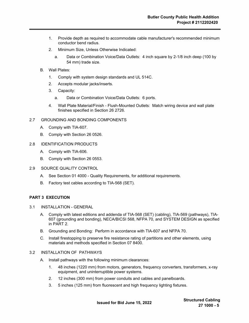
Butler County Public Health Addition Project # 2112202420
Issued for Bid June 15, 2022 Structured Cabling27 1000 - 5
1. Provide depth as required to accommodate cable manufacturer's recommended minimum conductor bend radius.
2. Minimum Size, Unless Otherwise Indicated:
a. Data or Combination Voice/Data Outlets: 4 inch square by 2-1/8 inch deep (100 by 54 mm) trade size.
B. Wall Plates:
1. Comply with system design standards and UL 514C.2. Accepts modular jacks/inserts.3. Capacity:
a. Data or Combination Voice/Data Outlets: 6 ports.
4. Wall Plate Material/Finish - Flush-Mounted Outlets: Match wiring device and wall plate finishes specified in Section 26 2726.
2.7 GROUNDING AND BONDING COMPONENTS
A. Comply with TIA-607.
B. Comply with Section 26 0526.
2.8 IDENTIFICATION PRODUCTS
A. Comply with TIA-606.
B. Comply with Section 26 0553.
2.9 SOURCE QUALITY CONTROL
A. See Section 01 4000 - Quality Requirements, for additional requirements.
B. Factory test cables according to TIA-568 (SET).
PART 3 EXECUTION
3.1 INSTALLATION - GENERAL
A. Comply with latest editions and addenda of TIA-568 (SET) (cabling), TIA-569 (pathways), TIA-607 (grounding and bonding), NECA/BICSI 568, NFPA 70, and SYSTEM DESIGN as specified in PART 2.
B. Grounding and Bonding: Perform in accordance with TIA-607 and NFPA 70.
C. Install firestopping to preserve fire resistance rating of partitions and other elements, using materials and methods specified in Section 07 8400.
3.2 INSTALLATION OF PATHWAYS
A. Install pathways with the following minimum clearances:
1. 48 inches (1220 mm) from motors, generators, frequency converters, transformers, x-ray equipment, and uninterruptible power systems.
2. 12 inches (300 mm) from power conduits and cables and panelboards.3. 5 inches (125 mm) from fluorescent and high frequency lighting fixtures.
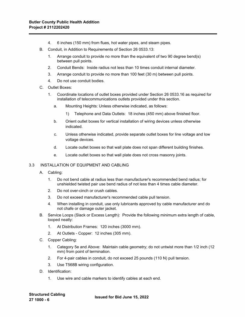
Butler County Public Health Addition Project # 2112202420
Structured Cabling 27 1000 - 6 Issued for Bid June 15, 2022
4. 6 inches (150 mm) from flues, hot water pipes, and steam pipes.B. Conduit, in Addition to Requirements of Section 26 0533.13:
1. Arrange conduit to provide no more than the equivalent of two 90 degree bend(s) between pull points.
2. Conduit Bends: Inside radius not less than 10 times conduit internal diameter.3. Arrange conduit to provide no more than 100 feet (30 m) between pull points.4. Do not use conduit bodies.
C. Outlet Boxes:
1. Coordinate locations of outlet boxes provided under Section 26 0533.16 as required for installation of telecommunications outlets provided under this section.
a. Mounting Heights: Unless otherwise indicated, as follows:
1) Telephone and Data Outlets: 18 inches (450 mm) above finished floor.
b. Orient outlet boxes for vertical installation of wiring devices unless otherwise indicated.
c. Unless otherwise indicated, provide separate outlet boxes for line voltage and low voltage devices.
d. Locate outlet boxes so that wall plate does not span different building finishes.
e. Locate outlet boxes so that wall plate does not cross masonry joints.
3.3 INSTALLATION OF EQUIPMENT AND CABLING
A. Cabling:
1. Do not bend cable at radius less than manufacturer's recommended bend radius; for unshielded twisted pair use bend radius of not less than 4 times cable diameter.
2. Do not over-cinch or crush cables.3. Do not exceed manufacturer's recommended cable pull tension.4. When installing in conduit, use only lubricants approved by cable manufacturer and do
not chafe or damage outer jacket.B. Service Loops (Slack or Excess Length): Provide the following minimum extra length of cable,
looped neatly:
1. At Distribution Frames: 120 inches (3000 mm).2. At Outlets - Copper: 12 inches (305 mm).
C. Copper Cabling:
1. Category 5e and Above: Maintain cable geometry; do not untwist more than 1/2 inch (12 mm) from point of termination.
2. For 4-pair cables in conduit, do not exceed 25 pounds (110 N) pull tension.3. Use T568B wiring configuration.
D. Identification:
1. Use wire and cable markers to identify cables at each end.
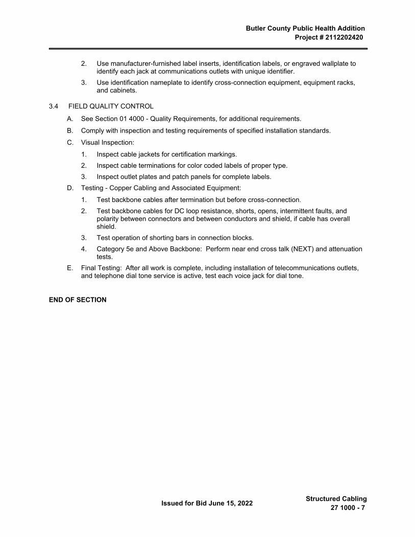
Butler County Public Health Addition Project # 2112202420
Issued for Bid June 15, 2022 Structured Cabling27 1000 - 7
2. Use manufacturer-furnished label inserts, identification labels, or engraved wallplate to identify each jack at communications outlets with unique identifier.
3. Use identification nameplate to identify cross-connection equipment, equipment racks, and cabinets.
3.4 FIELD QUALITY CONTROL
A. See Section 01 4000 - Quality Requirements, for additional requirements.
B. Comply with inspection and testing requirements of specified installation standards.
C. Visual Inspection:
1. Inspect cable jackets for certification markings.2. Inspect cable terminations for color coded labels of proper type.3. Inspect outlet plates and patch panels for complete labels.
D. Testing - Copper Cabling and Associated Equipment:
1. Test backbone cables after termination but before cross-connection.2. Test backbone cables for DC loop resistance, shorts, opens, intermittent faults, and
polarity between connectors and between conductors and shield, if cable has overall shield.
3. Test operation of shorting bars in connection blocks.4. Category 5e and Above Backbone: Perform near end cross talk (NEXT) and attenuation
tests.E. Final Testing: After all work is complete, including installation of telecommunications outlets,
and telephone dial tone service is active, test each voice jack for dial tone.
END OF SECTION

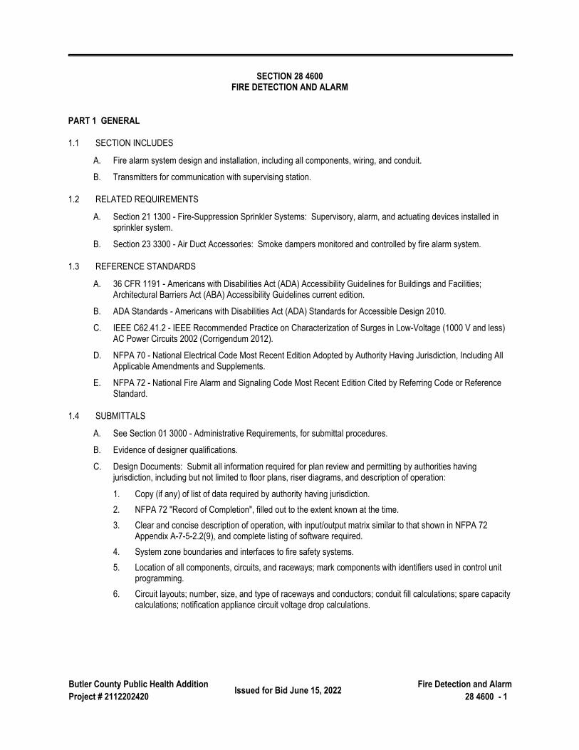
Butler County Public Health AdditionProject # 2112202420 Issued for Bid June 15, 2022 Fire Detection and Alarm
28 4600 - 1
SECTION 28 4600 FIRE DETECTION AND ALARM
PART 1 GENERAL
1.1 SECTION INCLUDES
A. Fire alarm system design and installation, including all components, wiring, and conduit.
B. Transmitters for communication with supervising station.
1.2 RELATED REQUIREMENTS
A. Section 21 1300 - Fire-Suppression Sprinkler Systems: Supervisory, alarm, and actuating devices installed in sprinkler system.
B. Section 23 3300 - Air Duct Accessories: Smoke dampers monitored and controlled by fire alarm system.
1.3 REFERENCE STANDARDS
A. 36 CFR 1191 - Americans with Disabilities Act (ADA) Accessibility Guidelines for Buildings and Facilities; Architectural Barriers Act (ABA) Accessibility Guidelines current edition.
B. ADA Standards - Americans with Disabilities Act (ADA) Standards for Accessible Design 2010.
C. IEEE C62.41.2 - IEEE Recommended Practice on Characterization of Surges in Low-Voltage (1000 V and less) AC Power Circuits 2002 (Corrigendum 2012).
D. NFPA 70 - National Electrical Code Most Recent Edition Adopted by Authority Having Jurisdiction, Including All Applicable Amendments and Supplements.
E. NFPA 72 - National Fire Alarm and Signaling Code Most Recent Edition Cited by Referring Code or Reference Standard.
1.4 SUBMITTALS
A. See Section 01 3000 - Administrative Requirements, for submittal procedures.
B. Evidence of designer qualifications.
C. Design Documents: Submit all information required for plan review and permitting by authorities having jurisdiction, including but not limited to floor plans, riser diagrams, and description of operation:
1. Copy (if any) of list of data required by authority having jurisdiction.2. NFPA 72 "Record of Completion", filled out to the extent known at the time.3. Clear and concise description of operation, with input/output matrix similar to that shown in NFPA 72
Appendix A-7-5-2.2(9), and complete listing of software required.4. System zone boundaries and interfaces to fire safety systems.5. Location of all components, circuits, and raceways; mark components with identifiers used in control unit
programming.6. Circuit layouts; number, size, and type of raceways and conductors; conduit fill calculations; spare capacity
calculations; notification appliance circuit voltage drop calculations.
Butler County Public Health Addition Project # 2112202420
Fire Detection and Alarm 28 4600 - 2 Issued for Bid June 15, 2022
7. List of all devices on each signaling line circuit, with spare capacity indicated.8. Manufacturer's detailed data sheet for each component, including wiring diagrams, installation instructions,
and circuit length limitations.9. Description of power supplies; if secondary power is by battery include calculations demonstrating
adequate battery power.10. Certification by either the manufacturer of the control unit or by the manufacturer of each other component
that the components are compatible with the control unit.11. Certification by the manufacturer of the control unit that the system design complies with the contract
documents.12. Certification by Contractor that the system design complies with the contract documents.
D. Evidence of installer qualifications.
E. Evidence of instructor qualifications; training lesson plan outline.
F. Inspection and Test Reports:
1. Submit inspection and test plan prior to closeout demonstration.2. Submit documentation of satisfactory inspections and tests.3. Submit NFPA 72 "Inspection and Test Form," filled out.
G. Operating and Maintenance Data: See Section 01 7800 for additional requirements; revise and resubmit until acceptable; have one set available during closeout demonstration:
1. Complete set of specified design documents, as approved by authority having jurisdiction.2. Additional printed set of project record documents and closeout documents, bound or filed in same
manuals.3. Contact information for firm that will be providing contract maintenance and trouble call-back service.4. List of recommended spare parts, tools, and instruments for testing.5. Replacement parts list with current prices, and source of supply.6. Detailed troubleshooting guide and large scale input/output matrix.7. Preventive maintenance, inspection, and testing schedule complying with NFPA 72; provide printed copy
and computer format acceptable to Owner.8. Detailed but easy to read explanation of procedures to be taken by non-technical administrative personnel
in the event of system trouble, when routine testing is being conducted, for fire drills, and when entering into contracts for remodeling.
H. Project Record Documents: See Section 01 7800 for additional requirements; have one set available during closeout demonstration:
1. Complete set of floor plans showing actual installed locations of components, conduit, and zones.2. "As installed" wiring and schematic diagrams, with final terminal identifications.3. "As programmed" operating sequences, including control events by device, updated input/output chart, and
voice messages by event.I. Closeout Documents:
Butler County Public Health Addition Project # 2112202420
Issued for Bid June 15, 2022 Fire Detection and Alarm28 4600 - 3
1. Certification by manufacturer that the system has been installed in compliance with manufacturer's installation requirements, is complete, and is in satisfactory operating condition.
2. NFPA 72 "Record of Completion", filled out completely and signed by installer and authorized representative of authority having jurisdiction.
1.5 QUALITY ASSURANCE
A. Designer Qualifications: NICET Level III or IV (3 or 4) certified fire alarm technician or registered fire protection engineer, employed by fire alarm control panel manufacturer, Contractor, or installer , with experience designing fire alarm systems in the jurisdictional area of the authorities having jurisdiction.
B. Installer Qualifications: Firm with minimum 3 years documented experience installing fire alarm systems of the specified type and providing contract maintenance service as a regular part of their business.
1. Authorized representative of control unit manufacturer; submit manufacturer's certification that installer is authorized; include name and title of manufacturer's representative making certification.
2. Installer Personnel: At least 2 years of experience installing fire alarm systems.3. Supervisor: NICET level III or IV (3 or 4) certified fire alarm technician; furnish name and address.
C. Instructor Qualifications: Experienced in technical instruction, understanding fire alarm theory, and able to provide the required training; trained by fire alarm control unit manufacturer.
D. Product Listing Organization Qualifications: An organization recognized by OSHA as a Nationally Recognized Testing Laboratory (NRTL) and acceptable to authorities having jurisdiction.
1.6 WARRANTY
A. See Section 01 7800 - Closeout Submittals, for additional warranty requirements.
B. Provide control panel manufacturer's warranty that system components other than wire and conduit are free from defects and will remain so for 1 year after date of Substantial Completion.
C. Provide installer's warranty that the installation is free from defects and will remain so for 1 year after date of Substantial Completion.
PART 2 PRODUCTS
2.1 MANUFACTURERS
A. Fire Alarm Control Units and Accessories:
1. Honeywell Security & Fire Solutions/Notifier: www.notifier.com.2. Potter Electric Signal Company: www.pottersignal.com/#sle.3. Edwards Signaling, United Technologies.4. Mircom Group - Secutron5. Siemens Building Technologies, Inc: www.usa.siemens.com.6. Simplex, a Tyco Business: www.simplex-fire.com.7. Provide control units made by the same manufacturer.
Butler County Public Health Addition Project # 2112202420
Fire Detection and Alarm 28 4600 - 4 Issued for Bid June 15, 2022
B. Initiating Devices and Notification Appliances:
1. Same manufacturer as control units.
2.2 FIRE ALARM SYSTEM
A. Fire Alarm System: Provide a new automatic fire detection and alarm system:
1. Provide all components necessary, regardless of whether shown in the contract documents or not.2. Protected Premises: Entire building shown on drawings.3. Comply with the following; where requirements conflict, order of precedence of requirements is as listed:
a. ADA Standards.
b. The requirements of the State Fire Marshal.
c. Applicable local codes.
d. The contract documents (drawings and specifications).
e. NFPA 72; where the word "should" is used consider that provision mandatory; where conflicts between requirements require deviation from NFPA 72, identify deviations clearly on design documents.
4. Evacuation Alarm: Single smoke zone; general evacuation of entire premises.5. General Evacuation Zones: Each smoke zone is considered a general evacuation zone unless otherwise
indicated, with alarm notification in all zones on the same floor, on the floor above, and the floor below.6. Program notification zones and voice messages as directed by Owner.7. Master Control Unit (Panel): New, located at location indicated on the plans..
B. Supervising Stations and Fire Department Connections:
1. Public Fire Department Notification: By remote supervising station.2. Means of Transmission to Remote Supervising Station: Digital alarm communicator transmitter (DACT), 2
telephone lines.C. Circuits:
1. Initiating Device Circuits (IDC): Class B, Style A.2. Signaling Line Circuits (SLC) Within Single Building: Class B, Style 0.5.3. Notification Appliance Circuits (NAC): Class B, Style W.
D. Power Sources:
1. Primary: Dedicated branch circuits of the facility power distribution system.2. Secondary: Storage batteries.3. Capacity: Sufficient to operate entire system for period specified by NFPA 72.4. Each Computer System: Provide uninterruptible power supply (UPS).
2.3 EXISTING COMPONENTS
Butler County Public Health Addition Project # 2112202420
Issued for Bid June 15, 2022 Fire Detection and Alarm28 4600 - 5
A. Existing Fire Alarm System: Remove existing system completely after new system is fully operational and tested.
B. Clearly label components that are "Not In Service."
C. Remove unused existing components and materials from site and dispose of properly.
2.4 FIRE SAFETY SYSTEMS INTERFACES
A. Supervision: Provide supervisory signals in accordance with NFPA 72 for the following:
1. Sprinkler water control valves.B. Alarm: Provide alarm initiation in accordance with NFPA 72 for the following:
1. Sprinkler water flow.
2.5 COMPONENTS
A. Fire Alarm Control Units: Conventional or addressable type; listed, classified, and labeled as suitable for the purpose intended.
B. Master Control Unit: As specified for Basis of Design above, or equivalent.
C. Initiating Devices:
1. Heat Detectors: rate of rise.D. Notification Appliances:
1. Speakers: Quam UL22/70.2. Strobes: 15,30,75,110 selectable.
E. Circuit Conductors: Copper or optical fiber; provide 200 feet (60 m) extra; color code and label.
F. Surge Protection: In accordance with IEEE C62.41.2 category B combination waveform and NFPA 70; except for optical fiber conductors.
1. Equipment Connected to Alternating Current Circuits: Maximum let through voltage of 350 V(ac), line-to-neutral, and 350 V(ac), line-to-line; do not use fuses.
2. Signaling Line Circuits: Provide surge protection at each point where circuit exits or enters a building, rated to protect applicable equipment.
G. Locks and Keys: Deliver keys to Owner.
1. Provide the same standard lock and key for each key operated switch and lockable panel and cabinet; provide 5 keys of each type
H. Instruction Charts: Printed instruction chart for operators, showing steps to be taken when a signal is received (normal, alarm, supervisory, and trouble); easily readable from normal operator's station.
1. Frame: Stainless steel or aluminum with polycarbonate or glass cover.2. Provide one for each control unit where operations are to be performed.3. Obtain approval of Owner prior to mounting; mount in location acceptable to Owner.4. Provide extra copy with operation and maintenance data submittal.
I. Documentation cabinet: Steel with baked enamel finish, size appropriate to to contain all neccessary documentation. cabinet shall be lockable and accessible by authorized personnel only. Labeld System Record Documents.
Butler County Public Health Addition Project # 2112202420
Fire Detection and Alarm 28 4600 - 6 Issued for Bid June 15, 2022
PART 3 EXECUTION
3.1 INSTALLATION
A. Install in accordance with applicable codes, NFPA 72, NFPA 70, and the contract documents.
B. Conceal all wiring, conduit, boxes, and supports where installed in finished areas.
C. Obtain Owner's approval of locations of devices, before installation.
D. Install instruction cards and labels.
E. Documentation cabinet:
1. installed at fire alarm panel or another approved location at the protected premises.2. all record documentation shall be stored in the documentation cabinet.3. no record documentation shall be stored in the control unit.4. when not at control unit indicate location of documentation cabinet at the control unit.5. emergency communication system and fire alarm system record documentation shall be permitted to be
maintained together in the same cabinet.
3.2 INSPECTION AND TESTING FOR COMPLETION
A. Notify Owner 7 days prior to beginning completion inspections and tests.
B. Notify authorities having jurisdiction and comply with their requirements for scheduling inspections and tests and for observation by their personnel.
C. Provide the services of the installer's supervisor or person with equivalent qualifications to supervise inspection and testing, correction, and adjustments.
D. Prepare for testing by ensuring that all work is complete and correct; perform preliminary tests as required.
E. Provide all tools, software, and supplies required to accomplish inspection and testing.
F. Perform inspection and testing in accordance with NFPA 72 and requirements of local authorities; document each inspection and test.
G. Correct defective work, adjust for proper operation, and retest until entire system complies with contract documents.
3.3 OWNER PERSONNEL INSTRUCTION
A. Provide the following instruction to designated Owner personnel:
1. Hands-On Instruction: On-site, using operational system.2. Classroom Instruction: Owner furnished classroom, on-site or at other local facility.
B. Administrative: One-hour session(s) covering issues necessary for non-technical administrative staff; classroom:
1. Initial Training: 1 session pre-closeout.C. Basic Operation: One-hour sessions for attendant personnel, security officers, and engineering staff;
combination of classroom and hands-on:
1. Initial Training: 1 session pre-closeout.D. Furnish the services of instructors and teaching aids; have copies of operation and maintenance data available
during instruction.
Butler County Public Health Addition Project # 2112202420
Issued for Bid June 15, 2022 Fire Detection and Alarm28 4600 - 7
3.4 CLOSEOUT
A. Closeout Demonstration: Demonstrate proper operation of all functions to Owner.
1. Be prepared to conduct any of the required tests.2. Have at least one copy of operation and maintenance data, preliminary copy of project record drawings,
input/output matrix, and operator instruction chart(s) available during demonstration.3. Have authorized technical representative of control unit manufacturer present during demonstration.4. Demonstration may be combined with inspection and testing required by authority having jurisdiction; notify
authority having jurisdiction in time to schedule demonstration.5. Repeat demonstration until successful.
END OF SECTION

Related Documents