Secoroc Down-the-hole Equipment Quantum Leap ® Technical Manual QL40 QL45 QL50 QL55 QL60 QL65 QL70 QL80 QL120 QL200 Technical Manual Read this instruction manual before operating this equipment.

Welcome message from author
This document is posted to help you gain knowledge. Please leave a comment to let me know what you think about it! Share it to your friends and learn new things together.
Transcript
Secoroc Down-the-hole Equipment
Quantum Leap® Technical ManualQL40QL45QL50QL55QL60QL65QL70QL80QL120QL200
Technical ManualRead this instruction manual before operating this equipment.

WARNING: This manual contains data SPECIFIC to QL Series Downhole Drills.
WARNING: This manual contains data SPECIFIC to QL Series Downhole Drills.
ENG
LIS
H
�WARNING: This manual contains data SPECIFIC to QL Series Downhole Drills.
CONTENTSRead this instruction manual before operating this equipment.
SAFETY ............................................................... 4 INSTALLATION AND OPERATION ................. 8 Follow Instructions Description
DTH Setup ........................................... 8 Setting up the DTH Valve, choke selection and Hydrocyclone® setup Bailing velocity requirements Valve selection Choke sizing Hydrocyclone® setup Bit installation New bit and chuck Makeup torque and backhead closure
Drill lubrication .................................. 10 Lubricators Lubrication check Water Injection
Drill operation ..................................... 11 Rotation speed Collaring Feed force Hole cleaning, flushing, and dust suppression Dry drilling Wet drilling Wet drilling with Hydrocyclone®
Bit changing ...................................... 13 Removing the drill bit Removing the bit with percussion only
MAINTENANCE AND REPAIR ........................ 14
DTH Service......................................... 14 Disassembly
Hydrocyclone® .................................... 19 Disassembly and service
DTH inspection ................................... 19 Inspection
DTH assembly ................................... 23 Assembly
Exhaust tube ...................................... 26 Replacement and installation
Bits ........................................................ 26 Selection Service Bit Sharpening
TROUBLESHOOTING ....................................... 28
SPECIFICATIONS .............................................. 31
ORDERING INSTRUCTIONS ........................... 33
PARTS LIST ....................................................... 34
Secoroc Down-the-hole Equipment
Quantum Leap® Technical ManualQL40 QL45QL50 QL55QL60 QL65QL70QL80QL120QL200

ENG
LIS
H
4 WARNING: This manual contains data SPECIFIC to QL Series Downhole Drills.WARNING: This manual contains data SPECIFIC to QL Series Downhole Drills.
WARNING: This manual contains data SPECIFIC to QL Series Downhole Drills.WARNING: This manual contains data SPECIFIC to QL Series Downhole Drills.
ENG
LIS
H
5WARNING: This manual contains data SPECIFIC to QL Series Downhole Drills.
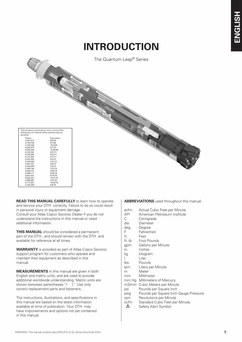
READ THIS MANUAL CAREFULLY to learn how to operate and service your DTH correctly. Failure to do so could result in personal injury or equipment damage. Consult your Atlas Copco Secoroc Dealer if you do not understand the instructions in this manual or need additional information.
THIS MANUAL should be considered a permanentpart of the DTH , and should remain with the DTH and available for reference at all times.
WARRANTY is provided as part of Atlas Copco Secorocsupport program for customers who operate andmaintain their equipment as described in this manual.
MEASUREMENTS in this manual are given in bothEnglish and metric units, and are used to provideadditional worldwide understanding. Metric units are shown between parentheses ‘’( )’’. Use onlycorrect replacement parts and fasteners.
The instructions, illustrations, and specifications inthis manual are based on the latest informationavailable at time of publication. Your DTH mayhave improvements and options not yet containedin this manual.
INTRODUCTIONThe Quantum Leap® Series
ABBREVIATIONS used throughout this manual.
acfm Actual Cubic Feet per MinuteAPI American Petroleum InstituteC Centigradedia. Diameterdeg. DegreeF Fahrenheitft. Feetft.-lb Foot Poundsgpm Gallons per Minutein. Incheskg kilograml Literlbs. Poundslpm Liters per Minutem Metermm Millimetermm Hg Millimeters of Mercurym3/min Cubic Meters per Minutepsi Pounds per Square Inchpsig Pounds per Square Inch Gauge Pressurerpm Revolutions per Minutescfm Standard Cubic Feet per Minute Safety Alert Symbol
This product is covered by one or more of the following U.S. Patents Other patents may be pending.
Patent Expiration4,821,812 9/8/084,706,764 8/1/064,729,4�9 10/2/065,025,875 5/7/105,085,284 12/26/095,14�,162 9/27/115,1�9,095 9/27/115,174,�90 5/17/11 5,207,28� �/2/125,240,08� 4/21/125,�01,761 �/9/1�5,�25,926 2/5/1�5,�90,749 1/�1/145,562,170 8/�0/155,566,771 8/�0/155,647,447 6/10/165,682,957 12/21/155,699,867 7/�1/165,711,205 10/�0/165,7�5,�58 6/6/16
ENG
LIS
H
6 WARNING: This manual contains data SPECIFIC to QL Series Downhole Drills.WARNING: This manual contains data SPECIFIC to QL Series Downhole Drills.
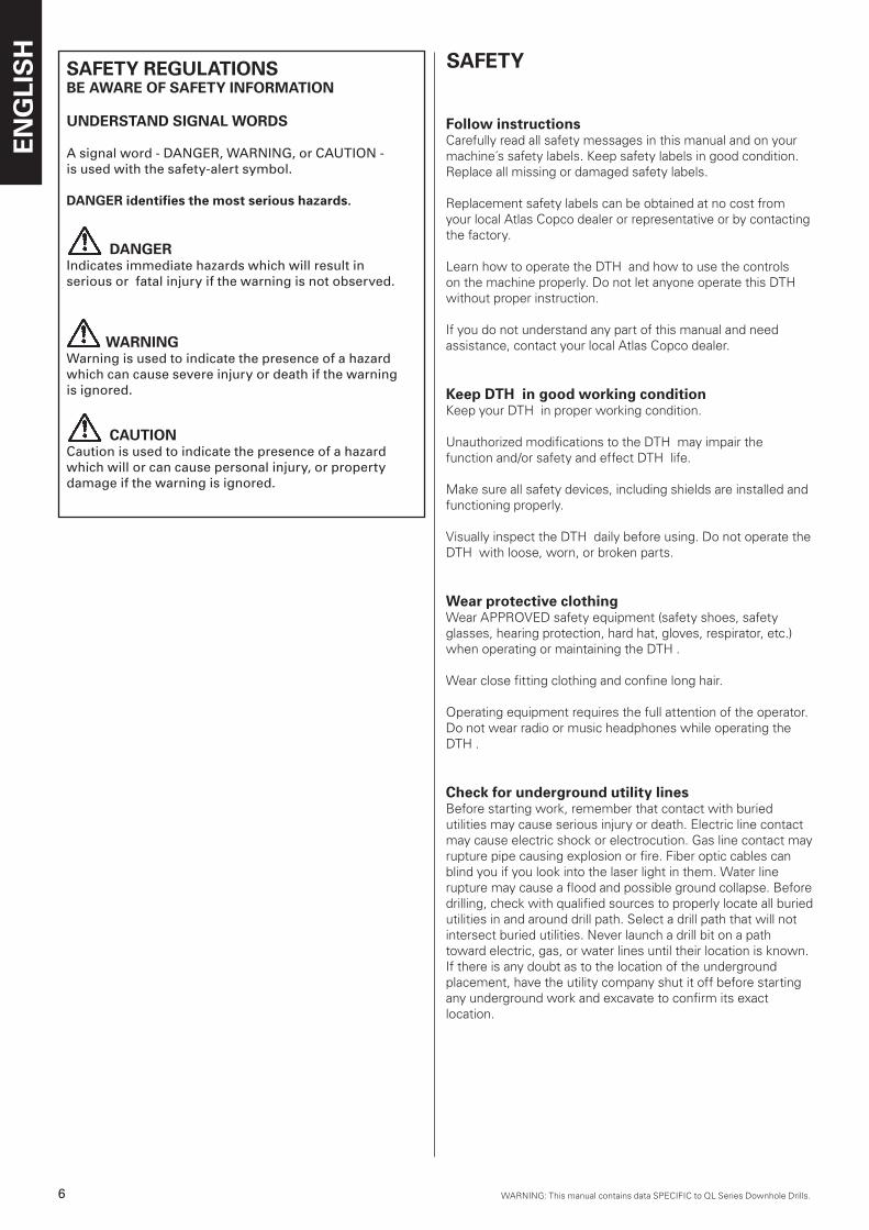
SAFETY REGULATIONSBE AWARE OF SAFETY INFORMATION
UNDERSTAND SIGNAL WORDS
A signal word - DANGER, WARNING, or CAUTION - is used with the safety-alert symbol.
DANGER identifies the most serious hazards.
DANGERIndicates immediate hazards which will result in serious or fatal injury if the warning is not observed.
WARNINGWarning is used to indicate the presence of a hazard which can cause severe injury or death if the warning is ignored.
CAUTION Caution is used to indicate the presence of a hazard which will or can cause personal injury, or property damage if the warning is ignored.
Follow instructionsCarefully read all safety messages in this manual and on your machine´s safety labels. Keep safety labels in good condition. Replace all missing or damaged safety labels.
Replacement safety labels can be obtained at no cost from your local Atlas Copco dealer or representative or by contacting the factory.
Learn how to operate the DTH and how to use the controls on the machine properly. Do not let anyone operate this DTH without proper instruction.
If you do not understand any part of this manual and need assistance, contact your local Atlas Copco dealer.
Keep DTH in good working conditionKeep your DTH in proper working condition.
Unauthorized modifications to the DTH may impair the function and/or safety and effect DTH life.
Make sure all safety devices, including shields are installed and functioning properly.
Visually inspect the DTH daily before using. Do not operate the DTH with loose, worn, or broken parts.
Wear protective clothingWear APPROVED safety equipment (safety shoes, safety glasses, hearing protection, hard hat, gloves, respirator, etc.) when operating or maintaining the DTH .
Wear close fitting clothing and confine long hair.
Operating equipment requires the full attention of the operator. Do not wear radio or music headphones while operating the DTH .
Check for underground utility linesBefore starting work, remember that contact with buried utilities may cause serious injury or death. Electric line contact may cause electric shock or electrocution. Gas line contact may rupture pipe causing explosion or fire. Fiber optic cables can blind you if you look into the laser light in them. Water linerupture may cause a flood and possible ground collapse. Before drilling, check with qualified sources to properly locate all buried utilities in and around drill path. Select a drill path that will not intersect buried utilities. Never launch a drill bit on a pathtoward electric, gas, or water lines until their location is known. If there is any doubt as to the location of the underground placement, have the utility company shut it off before starting any underground work and excavate to confirm its exact location.
SAFETY
WARNING: This manual contains data SPECIFIC to QL Series Downhole Drills.WARNING: This manual contains data SPECIFIC to QL Series Downhole Drills.
ENG
LIS
H
7WARNING: This manual contains data SPECIFIC to QL Series Downhole Drills.
Do not work in trenchDo not work in trench with unstable sides which could cave in. Specific requirements for shoring or sloping trench walls are available from several sources including Federal and State O.S.H.A. offices, and appropriate governing agency. Be sure to contact suitable authorities for these requirements beforeworking in a trench. Federal O.S.H.A. regulations can be obtained by contacting the Superintendent of Documents, U.S. Government Printing Office, Washington, D.C. 20402. State O.S.H.A. regulations are available at your local state O.S.H.A. office, and appropriate governing agency.
Check laws and regulationsKnow and obey all Federal, State, and Local, and appropriate governing agency laws and regulations that apply to your work situation.
Place warning barriers around work siteSet up orange cones around the work area with warning signs facing outward.
Place pedestrian and traffic barriers around the job site in accordance with Federal, State, and Local, and appropriate governing agency laws and regulations.
Observe environmental Protection regulationsBe mindful of the environment and ecology.
Before draining any fluids, find the correct way of disposing them.
Observe the relevant environmental protection regulations when disposing of oil, fuel, coolant, brake fluid, filters and batteries.
When using any solvent to clean parts, make sure that it is nonflammable, that it will not harm the skin, that it meets current O.S.H.A. standards, and appropriate governing agency, and that it is used in an area that is adequately ventilated.
WARNING
n Failure to follow any of the above safety instructions or those that follow within this manual, could result in serious injury or death. This DTH is to be used only for those purposes for which it was intended as explained in this instruction manual.
Avoid electrocution. Stay awayElectrocution possible. Serious injury or death may result if the machine strikes an energized powerline. Take the following precautions to prevent electrocution. Also refer to the operatinginstructions.
n Always contact your local utility company when working in the vicinity of utilities.
n Locate underground utilities by qualified persons.
n Do not raise, lower, or move drill guide or boom near power lines.
n Always wear proper electrically insulated linemanís gloves and boots.
n Never touch metal parts on machine while standing on bare ground if machine comes in contact with a powerline.
n Always stay in cab during all drilling operations.
n Never step onto or off of a machine if an electric strike occurs.
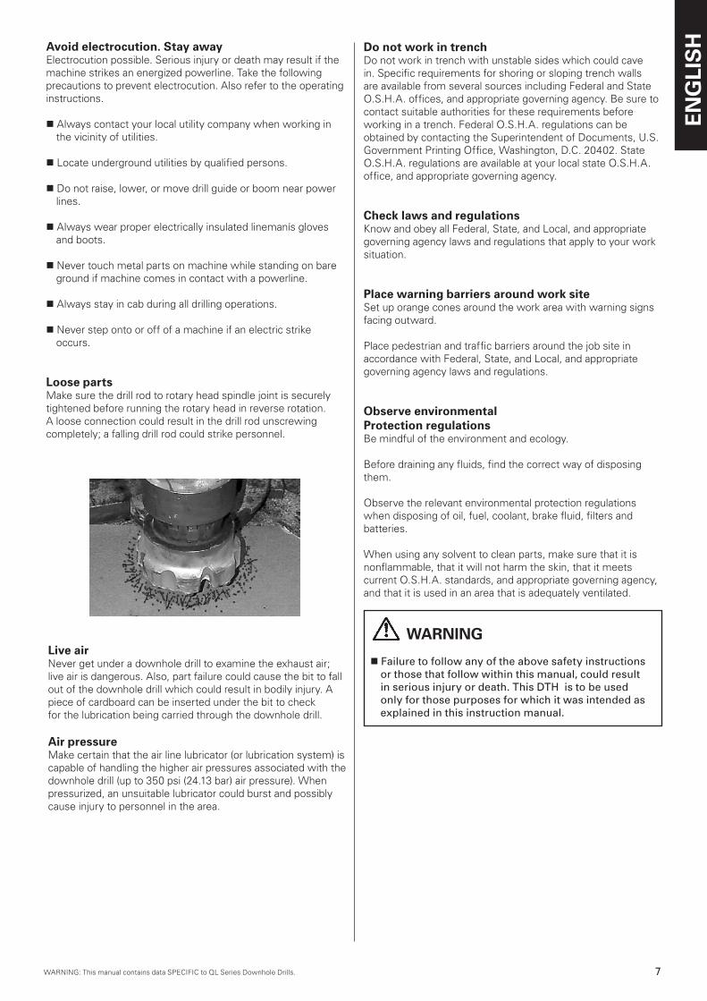
Loose partsMake sure the drill rod to rotary head spindle joint is securely tightened before running the rotary head in reverse rotation. A loose connection could result in the drill rod unscrewing completely; a falling drill rod could strike personnel.
Live airNever get under a downhole drill to examine the exhaust air; live air is dangerous. Also, part failure could cause the bit to fall out of the downhole drill which could result in bodily injury. A piece of cardboard can be inserted under the bit to checkfor the lubrication being carried through the downhole drill.
Air pressureMake certain that the air line lubricator (or lubrication system) is capable of handling the higher air pressures associated with the downhole drill (up to 350 psi (24.13 bar) air pressure). Whenpressurized, an unsuitable lubricator could burst and possibly cause injury to personnel in the area.
ENG
LIS
H
8 WARNING: This manual contains data SPECIFIC to QL Series Downhole Drills.WARNING: This manual contains data SPECIFIC to QL Series Downhole Drills.
INSTALLATION AND OPERATION
General information
Follow instructionsBefore operating this down-the-hole drill (DTH ) for the first time, become familiar with the operation of the machine and the DTH .
Learn how to operate the machine and how to use the controlsproperly. Do not let anyone operate this machine without proper instruction.
If you do not understand any part of this manual and needassistance, contact your local Atlas Copco dealer.
DescriptionThe Quantum Leap® line of (DTH ´s) are designed for use on drilling machines in conjunction with a top head or kelly drive mounting. The mounting must be capable of supplying sufficient hold down, hold back, rpm, torque, hammer lubrication, air pressure, and air volume.
DTH ´s achieve high productivity in hard rock applications by adding percussion to the drilling process. Rotary drilling methods use the combination of raw weight and rotation to chip and carve rock from a hole. The rotary method works fine in soft formations where adequate weight and stress can be applied to the rock to initiate fracture and chipping. However, in harder rock the rotary method cannot supply sufficientload on the bit inserts to crack the rock and produce a chip. Percussion drills overcome the rotary bit load limitation by producing a very high load during impact of the hammer. This load is sufficient to drive the cutting inserts into the rock to produce chips.
Quantum Leap® DTH ´s are recommended for practically any hard rock application. Depending on the size downhole drill being used, they are suitable for drilling water wells, primary blast holes in quarries, open pit mining, coal stripping operations, oil and gas exploration, and construction jobs where large volume rock excavation is required.
Common DTH ´s operate by using the position of a piston to direct supply and exhaust air to and from drive and return volumes. The drive volume ‘’drives’’ the piston toward impact and the return volume ‘’returns’’ the piston in preparation for another impact stroke. In order to maximize impact energy it isdesirable to deliver supply pressure to the drive volume while the piston is at the top of its stroke, and, turn off the supply pressure when the piston is nearly at its impacting position. However, conventional DTH ´s which use position dependent fixed porting are not able to alter the position at which supply pressure is delivered and shut off from the drive chamber. As a result, maximum efficiency and power are limited.
The Atlas Copco Quantum Leap® DTH cycle overcomes this inherent limitation by using a poppet valve to maximize efficiency. The poppet valve opens and directs supply air to the drive chamber at the top of the piston stroke and cuts off supply air just before impact. Variable drive volume supply timing is the key difference between the Quantum Leap® cycle and common DTH cycles.
DTH Setup
Before the DTH is used to drill it should be set up for proper air consumption and the joints should be tightened. The selection of choke size and/or valve lift will be dependent on the hole cleaning requirements and the capacity (pressure and flow) of the compressor being used. Hammer air consumption should be set up for the best balance of power and hole cleaning. Other factors which need to be considered are depth of hole, water to be encountered and water to be injected. In some cases, where such factors are unpredictable, the proper choke size can only be selected after experience is developed.
Valve, Choke selection and Hydrocyclone® SetupThe best performance of any DTH will be achieved when a maximum volume of air can be passed through the drill with a solid choke. Under ideal conditions the pressure required to drive this volume through the drill will be within the capabilities of the compressor. All Quantum Leap® DTH ´s have a choke plug which can be changed for additional hole cleaning capacity if additional hole cleaning air is needed and compressor capacity is sufficient.
Bailing velocity requirementsThe need for adequate hole cleaning cannot be emphasized enough. A hole that is not cleaned properly can result in poor performance, rapid wear of bits and accessories and in some cases loss of the drill and pipe down the hole. Hole cleaning is usually directly related to what is called bailing velocity or the speed of the air which is lifting cuttings from the hole.
Bailing velocity is defined as the velocity of the air in the hole annulus at atmospheric pressure. In other words, the effect of bottom hole pressure is not taken into account when computing bailing velocity. For conventional hole cleaning (no soaps or foams) bailing velocity should exceed 3000 ft./min. (914.4 m/min.). However, if possible, bailing velocity should not exceed 7000 ft./min. (2133 m/min.). Bailing velocity can be computed by dividing the air consumption of the DTH in scfmby the annulus area in square feet. The equation following may be used:
Velocity [ft./min.] (m/min.) = Air consumption [scfm] (m3/min.)
Annulus area [sq. ft.] (sq. m)
where:n Air consumption is the rated delivery of the compressor
or the air consumption of the drill at maximum pressure, whichever is less.
n Annulus area is the area between the hole bore and the drill rod. It can be computed as follows:
n Annulus area [sq. ft.] =.0055 x (hole dia. [inches]2 - rod dia. [inches]2) (sq. m) =.785 x (hole dia. [m]2 - rod dia. [m]2)
The sections following explain how to adjust the choke or valve to increase air consumption.
Valve selection (QL40, QL60/65, QL80HF, QL 120 only)The QL60 and QL65 can use two valves. The lift of these valves differs by .030 in. (7.62 mm). The higher lift valve allows more air and power to be delivered to the drive chamber. QL60´s and QL65QM´s come factory equipped with the low lift valve installed. The high lift valve is supplied as an accessory
WARNING: This manual contains data SPECIFIC to QL Series Downhole Drills.WARNING: This manual contains data SPECIFIC to QL Series Downhole Drills.
ENG
LIS
H
9WARNING: This manual contains data SPECIFIC to QL Series Downhole Drills.
for the QL65QM and sold separately for the QL60.The low lift valve is suggested for use on 900 scfm (25.5 m3/min.) and lower air compressors. The high lift valve is suggested for use on compressors larger than 900 scfm (25.5 m3/min.). However, it is suggested that in deep holes greater than 500 ft. (152.4 m) the low lift valve be used all the time regardless of compressor capacity.The two valves can be identified by the presence of a groove on the outer diameter of the high lift valve. Conversely, the low lift valve has a smooth outer diameter.
The QL50, QL50HF, QL55QM and QL55QM-HF can also use two valves. The lift of these valves differs by .015. The higher lift valve allows more air and power to be delivered to thedrive chamber. The higher lift valve is an optional item and recommended for 900 scfm (25.5 m3/min.) and higher capacity compressors.
The QL40, QL80HF and QL120 use stainless steel shims to adjust air flow by limiting valve lift. QL120´s ship with the shim installed. QL40´s and QL80HF´s ship without the shim installed. Refer to the air consumption curve to determine if the shim should be removed. It is highly recommended that the proper valve setup be used for adjusting air consumption before choke adjustments are made.
Shim addition or removal on the QL40, QL80HF, and QL120 may be useful for certain applications. For example,
n Installing the shim on the QL40 maybe useful in applications where casing wear is excessive. Bear in mind that a reduction in air consumption will reduce penetration rate. If fuel consumption must be minimized, at the expense of the penetration rate, it may useful to install the valve shim.
n Installing the shim on the QL80 will be useful on any 1050 scfm (30.7 m3/min.) compressor. It will also be beneficial on larger volume compressors operating at altitudes greater than 4000 ft. (1219 m).
n Removing the shim on the QL120 is generally suggested for deep-hole applications where air consumption must be increased for hole cleaning.
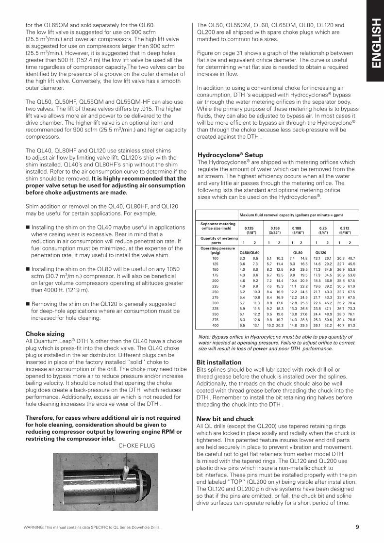
Choke sizingAll Quantum Leap® DTH ´s other then the QL40 have a choke plug which is press-fit into the check valve. The QL40 choke plug is installed in the air distributor. Different plugs can beinserted in place of the factory installed ‘’solid’’ choke to increase air consumption of the drill. The choke may need to be opened to bypass more air to reduce pressure and/or increase bailing velocity. It should be noted that opening the choke plug does create a back-pressure on the DTH which reduces performance. Additionally, excess air which is not needed for hole cleaning increases the erosive wear of the DTH .
Therefore, for cases where additional air is not required for hole cleaning, consideration should be given to reducing compressor output by lowering engine RPM or restricting the compressor inlet. CHOKE PLUG
The QL50, QL55QM, QL60, QL65QM, QL80, QL120 and QL200 are all shipped with spare choke plugs which are matched to common hole sizes.
Figure on page 31 shows a graph of the relationship between flat size and equivalent orifice diameter. The curve is useful for determining what flat size is needed to obtain a required increase in flow.
In addition to using a conventional choke for increasing air consumption, DTH ´s equipped with Hydrocyclones® bypass air through the water metering orifices in the separator body. While the primary purpose of these metering holes is to bypass fluids, they can also be adjusted to bypass air. In most cases it will be more efficient to bypass air through the Hydrocyclone® than through the choke because less back-pressure will be created against the DTH .
Hydrocyclone® SetupThe Hydrocyclones® are shipped with metering orifices which regulate the amount of water which can be removed from the air stream. The highest efficiency occurs when all the water and very little air passes through the metering orifice. The following lists the standard and optional metering orificesizes which can be used on the Hydrocyclones®.
Maxium fluid removal capacity (gallons per minute = gpm)
Separator metering orifice size (inch) 0.125 0.156 0.188 0.25 0.312 (1/8”) (3/32”) (3/16”) (1/4”) (5/16”)Quantity of metering ports 1 2 1 2 1 2 1 2 1 2Operating pressure (psig) QL50/QL60 QL80 QL120
100 �.� 6.5 5.1 10.2 7.4 14.8 1�.1 26.1 20.� 40.7
125 �.6 7.� 5.7 11.4 8.� 16.5 14.6 29.2 22.7 45.5
150 4.0 8.0 6.2 12.5 9.0 29.5 17.� �4.5 26.9 5�.8
175 4.� 8.6 6.7 1�.5 9.8 19.5 17.� �4.5 26.9 5�.8
200 4.6 9.2 7.2 14.4 10.4 20.9 18.5 �6.9 28.8 57.5
225 4.9 9.8 7.6 15.� 11.1 22.2 19.6 �9.2 �0.5 61.0
250 5.2 10.� 8.4 16.9 12.2 24.5 21.7 4�.� ��.7 67.5
275 5.4 10.8 8.4 16.9 12.2 24.5 21.7 4�.� ��.7 67.5
�00 5.7 11.� 8.8 17.6 12.8 25.6 22.6 45.2 �5.2 70.4
�25 5.9 11.8 9.2 18.� 1�.� 26.6 2�.5 47.1 �6.7 7�.�
�50 6.1 12.2 9.5 19.0 1�.8 27.6 24.4 48.9 �8.0 76.1
�75 6.� 12.6 9.8 19.7 14.� 28.6 25.� 50.6 �9.4 78.8
400 6.5 1�.1 10.2 20.� 14.8 29.5 26.1 52.2 40.7 81.�
Note: Bypass orifice in Hydrocylcone must be able to pas quantity of water injected at operaing pressure. Failure to adjust orifice to correct size will result in loss of power and poor DTH performance.
Bit installationBits splines should be well lubricated with rock drill oil or thread grease before the chuck is installed over the splines. Additionally, the threads on the chuck should also be well coated with thread grease before threading the chuck into the DTH . Remember to install the bit retaining ring halves before threading the chuck into the DTH .
New bit and chuckAll QL drills (except the QL200) use tapered retaining rings which are locked in place axially and radially when the chuck is tightened. This patented feature insures lower end drill parts are held securely in place to prevent vibration and movement. Be careful not to get flat retainers from earlier model DTH ís mixed with the tapered rings. The QL120 and QL200 use plastic drive pins which insure a non-metallic chuck tobit interface. These pins must be installed properly with the pin end labeled ‘’TOP’’ (QL200 only) being visible after installation. The QL120 and QL200 pin drive systems have been designed so that if the pins are omitted, or fail, the chuck bit and spline drive surfaces can operate reliably for a short period of time.
ENG
LIS
H
10 WARNING: This manual contains data SPECIFIC to QL Series Downhole Drills.WARNING: This manual contains data SPECIFIC to QL Series Downhole Drills.
Used bit and chuckCaution must be used when installing a new bit on a used chuck or visa-versa. Some applications, usually soft rock where there is excessive bit travel within the splines, can develop uneven wear on the bit and chuck splines. When a new bit is installed within a used chuck there is likely to be poor matingsurfaces. Check the condition of the chuck or bit splines when using a new bit or chuck if your application is prone to this form of spline wear.
It is also suggested that the chuck be rotated relative to the bit splines from time to time to even out the gouging and grooving which takes place due to erosive wear. This practice will extend your chuck and casing life.
Makeup torque and backhead closureThe Quantum Leap® drills have two forms of locking means for internal components; the QL4, QL120 and QL200 use relatively low-load belleville springs, all others use ‘’solid clamping’’ arrangement whereby parts are held in place under very high load.
Rotary head torque is usually sufficient to close the QL4 backhead. The QL200 uses a special wrench to close the backhead. However, because of the high load used to clamp the parts in place in the QL40, QL50, QL60, QL80, and QL120; a high level of torque is needed to close the backhead gap. Rotary head torque is not sufficient to close the backhead gap.A supplementary wrench is needed to properly tighten the joint. It is extremely important that the backhead gap be closed in these drills.
The presence of a gap between the casing and the backhead while drilling will increase the chances for loosening the backhead in the hole and possibly losing the drill.
In addition to at least closing the backhead gap, it is also recommended that the backhead and chuck be torqued to approximately 750 - 1000 ft.-lb per inch (40.5 - 54 N-m per mm) of hammer diameter. For example a 5 in. (127mm) class DTH (QL50) should be torqued to 3750 - 5000 ft.-lb (5143.5 - 6858 N-m). This makeup torque insures against loosening joints in the hole and also preloads the threads sufficiently.
Drill lubrication
Lubrication guidelines and specificationsAll DTH ´s require oil lubrication to resist wear, galling and corrosion. Additionally, the film of oil coating all internal parts seals internal clearance paths to reduce power-robbing leakageacross sealing clearances. As a general rule of thumb the oil required is proportional to the volume of air being used.
Oil also needs to be of sufficiently high quality. It is recommended that Atlas Copco Supertac rock drill oil be used. If another type of oil is used it must comply with the oil specifications shown in table on page 32.
For dry drilling (less than 2 gpm (7.6 lpm) of water injection) it is generally recommended that oil be injected into the drill air stream at the rate of 1/3 pint (.16 l) of oil per hour for every 100 scfm (2.8 m3/min.) of air. For example a 900 scfm (25.5 m3/min.) compressor delivering full flow to a DTH would require 900 ÷ 100 x 1/3 = 3 pints per hour (25.5 ÷ 2.8 x .16 = 1.6 l per hour).
For wet drilling (more than 2 gpm (7.6 lpm)), and in particular when using a Hydrocyclone® water separator, it is suggested that the lubrication rate be doubled to2/3 pint (.32 l) of oil per hour for every 100 scfm (2.8 m3/min.) of air.
The additional oil compensates for the wash-out caused by water and the oil losses caused by the Hydrocyclone®.
LubricatorsThere are two primary types of lubricators; a plunger oiler and a venturi oiler:
A plunger oiler normally operates from a timed plunger system which delivers a fixed ‘’slug’’ of oil into the line in timed intervals. These systems are beneficial in that the oil reservoirdoes not need to contain a high pressure. Plunger lubricators are also insensitive to oil viscosity and temperature. However, because of their complexity, the reliability of plunger lubricators is not as good as the venturi type. Also, because oil is delivered as ‘’slugs’’ it is not atomized and delivered to the drill internals as evenly as a venturi.
Venturi type lubricators (sometimes referred to as pig oilers) operate in a similar fashion to a gasoline carburetor. A necked down area in the venturi creates a pressure drop which drawsoil into the air stream. The oil is atomized and mixed very efficiently with the air providing maximum coverage and cohesion to internal drill components. A needle valve is usually used to adjust the oil volume delivered. Disadvantages of the venturi oiler are that it requires a pressurized volume, which is generally small in volume. Also, the lubrication rate isdependent on oil viscosity which varies with temperature.
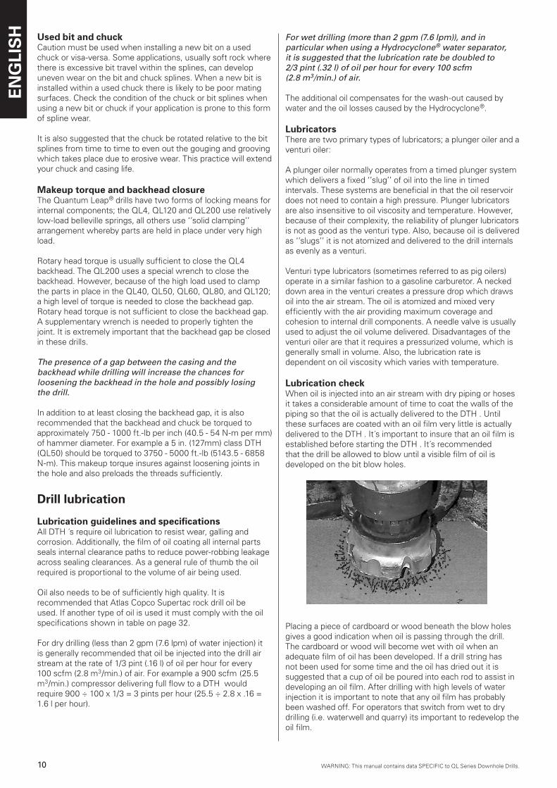
Lubrication checkWhen oil is injected into an air stream with dry piping or hoses it takes a considerable amount of time to coat the walls of the piping so that the oil is actually delivered to the DTH . Until these surfaces are coated with an oil film very little is actually delivered to the DTH . It´s important to insure that an oil film is established before starting the DTH . It´s recommendedthat the drill be allowed to blow until a visible film of oil is developed on the bit blow holes.
Placing a piece of cardboard or wood beneath the blow holes gives a good indication when oil is passing through the drill. The cardboard or wood will become wet with oil when anadequate film of oil has been developed. If a drill string has not been used for some time and the oil has dried out it is suggested that a cup of oil be poured into each rod to assist indeveloping an oil film. After drilling with high levels of water injection it is important to note that any oil film has probably been washed off. For operators that switch from wet to drydrilling (i.e. waterwell and quarry) its important to redevelop the oil film.
WARNING: This manual contains data SPECIFIC to QL Series Downhole Drills.WARNING: This manual contains data SPECIFIC to QL Series Downhole Drills.
ENG
LIS
H
11WARNING: This manual contains data SPECIFIC to QL Series Downhole Drills.
Water injectionWater injection can cause a DTH to either consume more air (hold a lower pressure) or less air (hold a higher pressure) depending on the volume of fluids injected. For example, if a DTH is lubricated with oil and water is then injected at a low rate (less than 1 gpm (3.8 lpm)), the oil film which is sealing the internal leak paths is washed out and air consumption will increase (pressure will fall).
Conversely, if water is injected at a high rate (more than 3 gpm (11.4 lpm)) the fluid level will be sufficient to seal the leak paths and restrict the flow of air through the DTH . In this case the airconsumption will decrease (pressure will increase).
The pressure rise associated with water injection can sometimes exceed the maximum pressure rating of a compressor. In these cases the choke or Hydrocyclone bypass hole must be increased to reduce pressure.
The use of water, while required in most cases, does reduce component life. The following lists some of the problems that water injection can cause:
nPoor quality water can either be corrosive or can carry contamination into the drill. Premature wear or corrosion related failures can result. All water injected into a DTH should be neutral in pH and free from particulate contamination.
nWater injection reduces drill performance considerably. Water restricts the flow and resultant pressure in working
chambers of the drill and reduces face cleaning which causes regrinding of cuttings.
nWater present at the impact face causes cavitation of the bit and piston and jetting or cutting of the exhaust tube. In both cases component life is reduced.
A DTH that has been operated with water injection and will be idle for more than a few days should be dried out and lubricated with oil. This can be accomplished by blowing lubricated air through the tool when drilling is finished.
QL60 Non-lube instructionsThe QL60 non-lube does not require injected oil or other lubricants. However, the use of oil will not harm the DTH . The following operational considerations are required.
n A minimum of 1/4 gpm (1 lpm) of water is needed to lubricate and cool the internal seals. It is suggested that at least a ‘’mist’’ of water be used even while driving casing.
n Use of the QL60 non-lube for quarry applications is not recommended unless; The minimum water injection rate is observed, and,
n The chances of getting stuck and overheating the drill are minimal. The addition of frictional heat can be sufficient to melt the piston seals and bearings.
n A Hydrocyclone can be used on the QL60 non-lube. Sufficient water bypasses the Hydrocyclone to permit adequate cooling of the seals and bearings.
QL60 Non-lube instructions n Because there is usually no oil present in the QL60 non-lube
to prevent corrosion, it is important to oil the DTH if it will be idle for more than two days. The following process is suggested.
n While the cylinder and casing have been specially heat treated to resist corrosion, other internal parts need the protection of oil when not being used.
n Fill the backhead bore, or last joint, with approximately 1 pint (0.5 Liter) of oil (motor oil is fine),
n Re-connect and cycle the drill on a block of wood at low pressure (50-100 psi) for approx. 15 seconds.
Drill operation
Rotation speedRotation speed directly affects the amount of angular index the bit inserts go through from one impact to the next. The optimum amount of index is dependent on variables such as blow energy (pressure), rock hardness, bit diameter, etc. The ideal rotation speed produces the best overall balance of penetration rate, bit life and smoothness of operation. It generally occurs when cuttings are their largest.
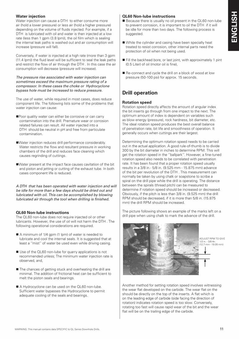
Determining the optimum rotation speed needs to be carried out in the actual application. A good rule-of-thumb is to divide 300 by the bit diameter in inches to determine RPM. This will get the rotation speed in the ‘’ballpark’’. However, a fine-tuned rotation speed also needs to be correlated with penetration rate. It has been found that a proper rotation speed usually results in a 3/8 in.- 5/8 in. (9.525 mm - 15.875 mm) advance of the bit per revolution of the DTH . This measurement can normally be taken by using chalk or soapstone to scribe a spiral on the drill pipe while the drill is operating. The distance between the spirals (thread pitch) can be measured to determine if rotation speed should be increased or decreased. Obviously, if the pitch is less than 3/8 in. (9.525 mm) the drill RPM should be decreased, if it is more than 5/8 in. (15.875 mm) the drill RPM should be increased.
The picture following shows an example of the marks left on a drill pipe when using chalk to mark the advance of the drill.
Another method for setting rotation speed involves witnessing the wear flat developed on the carbide. The wear flat on the should be directly on the top of the inserts. A flat which is on the leading edge of carbide (side facing the direction of rotation) indicates rotation speed is too slow. Conversely, rotating too fast will cause rapid wear of the bit and the wear flat will be on the trailing edge of the carbide.
ADJUST RPM TO GIVE1/2 in. - 3/8 4n.(12.7 mm - 19.05 mm)
ENG
LIS
H
12 WARNING: This manual contains data SPECIFIC to QL Series Downhole Drills.WARNING: This manual contains data SPECIFIC to QL Series Downhole Drills.
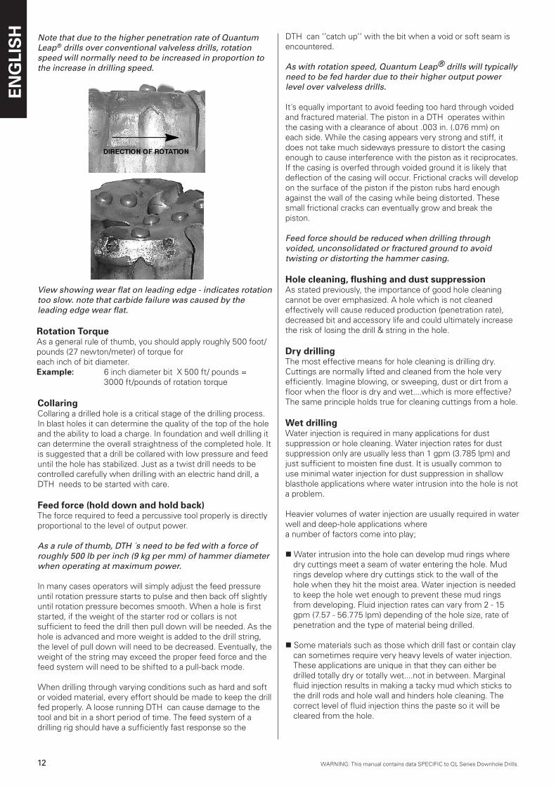
Note that due to the higher penetration rate of Quantum Leap® drills over conventional valveless drills, rotation speed will normally need to be increased in proportion to the increase in drilling speed.
View showing wear flat on leading edge - indicates rotation too slow. note that carbide failure was caused by the leading edge wear flat.
CollaringCollaring a drilled hole is a critical stage of the drilling process. In blast holes it can determine the quality of the top of the hole and the ability to load a charge. In foundation and well drilling itcan determine the overall straightness of the completed hole. It is suggested that a drill be collared with low pressure and feed until the hole has stabilized. Just as a twist drill needs to becontrolled carefully when drilling with an electric hand drill, a DTH needs to be started with care.
Feed force (hold down and hold back)The force required to feed a percussive tool properly is directly proportional to the level of output power.
As a rule of thumb, DTH ´s need to be fed with a force of roughly 500 lb per inch (9 kg per mm) of hammer diameter when operating at maximum power.
In many cases operators will simply adjust the feed pressure until rotation pressure starts to pulse and then back off slightly until rotation pressure becomes smooth. When a hole is firststarted, if the weight of the starter rod or collars is not sufficient to feed the drill then pull down will be needed. As the hole is advanced and more weight is added to the drill string, the level of pull down will need to be decreased. Eventually, the weight of the string may exceed the proper feed force and the feed system will need to be shifted to a pull-back mode.
When drilling through varying conditions such as hard and soft or voided material, every effort should be made to keep the drill fed properly. A loose running DTH can cause damage to thetool and bit in a short period of time. The feed system of a drilling rig should have a sufficiently fast response so the
DTH can ‘’catch up’’ with the bit when a void or soft seam is encountered.
As with rotation speed, Quantum Leap® drills will typically need to be fed harder due to their higher output power level over valveless drills.
It´s equally important to avoid feeding too hard through voided and fractured material. The piston in a DTH operates within the casing with a clearance of about .003 in. (.076 mm) on each side. While the casing appears very strong and stiff, it does not take much sideways pressure to distort the casing enough to cause interference with the piston as it reciprocates. If the casing is overfed through voided ground it is likely that deflection of the casing will occur. Frictional cracks will develop on the surface of the piston if the piston rubs hard enough against the wall of the casing while being distorted. These small frictional cracks can eventually grow and break thepiston.
Feed force should be reduced when drilling through voided, unconsolidated or fractured ground to avoid twisting or distorting the hammer casing.
Hole cleaning, flushing and dust suppressionAs stated previously, the importance of good hole cleaning cannot be over emphasized. A hole which is not cleaned effectively will cause reduced production (penetration rate), decreased bit and accessory life and could ultimately increase the risk of losing the drill & string in the hole.
Dry drillingThe most effective means for hole cleaning is drilling dry. Cuttings are normally lifted and cleaned from the hole very efficiently. Imagine blowing, or sweeping, dust or dirt from a floor when the floor is dry and wet....which is more effective? The same principle holds true for cleaning cuttings from a hole.
Wet drillingWater injection is required in many applications for dust suppression or hole cleaning. Water injection rates for dust suppression only are usually less than 1 gpm (3.785 lpm) and just sufficient to moisten fine dust. It is usually common to use minimal water injection for dust suppression in shallow blasthole applications where water intrusion into the hole is not a problem.
Heavier volumes of water injection are usually required in water well and deep-hole applications wherea number of factors come into play;
n Water intrusion into the hole can develop mud rings where dry cuttings meet a seam of water entering the hole. Mud rings develop where dry cuttings stick to the wall of the hole when they hit the moist area. Water injection is needed to keep the hole wet enough to prevent these mud rings from developing. Fluid injection rates can vary from 2 - 15 gpm (7.57 - 56.775 lpm) depending of the hole size, rate of penetration and the type of material being drilled.
n Some materials such as those which drill fast or contain clay can sometimes require very heavy levels of water injection. These applications are unique in that they can either be drilled totally dry or totally wet....not in between. Marginal fluid injection results in making a tacky mud which sticks to the drill rods and hole wall and hinders hole cleaning. The correct level of fluid injection thins the paste so it will be cleared from the hole.
Rotation TorqueAs a general rule of thumb, you should apply roughly 500 foot/pounds (27 newton/meter) of torque for each inch of bit diameter. Example: 6 inch diameter bit X 500 ft/ pounds = 3000 ft/pounds of rotation torque
WARNING: This manual contains data SPECIFIC to QL Series Downhole Drills.WARNING: This manual contains data SPECIFIC to QL Series Downhole Drills.
ENG
LIS
H
1�WARNING: This manual contains data SPECIFIC to QL Series Downhole Drills.
Wet drilling with Hydrocyclone®
Many of the compromises associated with water injection are eliminated when using a Hydrocyclone® water separator. With the Hydrocyclone®, as much water as needed can be injected without a significant loss in performance. The Hydrocyclone® will typically remove approximately 98% of the fluids injected until the bypass orifice becomes saturated and cannot pass any more water.
If the Hydrocyclone® bypass orifice is not large enough to pass all the fluid being injected, the remainder of fluid will pass through the drill as if the Hydrocyclone® was not present. However, a portion of the benefits associated with using the Hydrocyclone® will be lost. If this does occur it is suggested that the bypass orifice within the Hydrocyclone be enlarged to pass the additional volume of fluid. See previous paragraphs and table on page 8 involving Hydrocyclone® setup.
Because the Hydrocyclone® removes matter that´s heavier than air, it removes rust scale, small rocks and other debris in addition to fluids. As a result, the Hydrocyclone® can become clogged with debris. It is suggested that after every hole, the ports in the Hydrocyclone® backhead are checked to be open.This can be determined simply by witnessing the passage of air or fluid through the ports while blowing air. If they are clogged refer to the service and maintenance section for repair instructions.
Insure Hydrocyclone® backhead ports are passing air at the end of each hole.
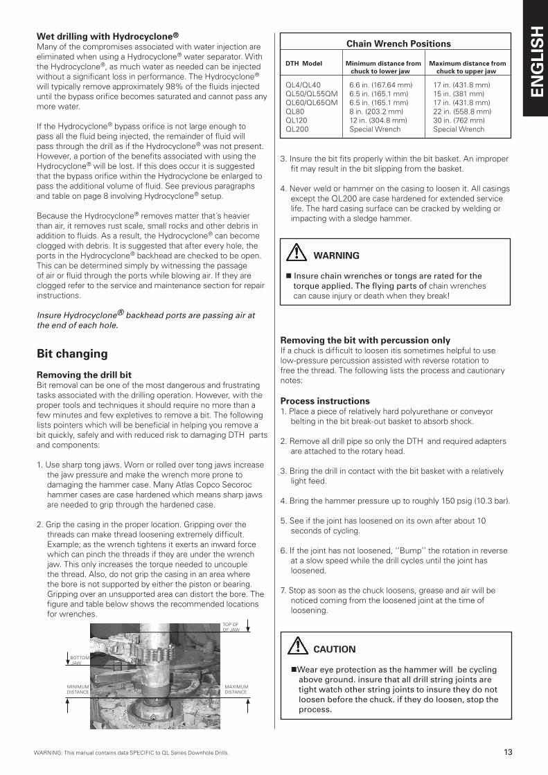
Chain Wrench Positions
DTH Model Minimum distance from Maximum distance from chuck to lower jaw chuck to upper jaw
QL4/QL40 6.6 in. (167.64 mm) 17 in. (431.8 mm)QL50/QL55QM 6.5 in. (165.1 mm) 15 in. (381 mm)QL60/QL65QM 6.5 in. (165.1 mm) 17 in. (431.8 mm)QL80 8 in. (203.2 mm) 22 in. (558.8 mm)QL120 12 in. (304.8 mm) 30 in. (762 mm)QL200 Special Wrench Special Wrench
3. Insure the bit fits properly within the bit basket. An improper fit may result in the bit slipping from the basket.
4. Never weld or hammer on the casing to loosen it. All casings except the QL200 are case hardened for extended service life. The hard casing surface can be cracked by welding or impacting with a sledge hammer.
WARNING
n Insure chain wrenches or tongs are rated for the torque applied. The flying parts of chain wrenches can cause injury or death when they break!
Removing the bit with percussion onlyIf a chuck is difficult to loosen itís sometimes helpful to use low-pressure percussion assisted with reverse rotation to free the thread. The following lists the process and cautionary notes:
Process instructions1. Place a piece of relatively hard polyurethane or conveyor
belting in the bit break-out basket to absorb shock.
2. Remove all drill pipe so only the DTH and required adapters are attached to the rotary head.
3. Bring the drill in contact with the bit basket with a relatively light feed.
4. Bring the hammer pressure up to roughly 150 psig (10.3 bar).
5. See if the joint has loosened on its own after about 10 seconds of cycling.
6. If the joint has not loosened, ‘’Bump’’ the rotation in reverse at a slow speed while the drill cycles until the joint has loosened.
7. Stop as soon as the chuck loosens, grease and air will be noticed coming from the loosened joint at the time of loosening.
CAUTION
nWear eye protection as the hammer will be cycling above ground. insure that all drill string joints are tight watch other string joints to insure they do not loosen before the chuck. if they do loosen, stop the process.
Removing the drill bitBit removal can be one of the most dangerous and frustrating tasks associated with the drilling operation. However, with the proper tools and techniques it should require no more than a few minutes and few expletives to remove a bit. The following lists pointers which will be beneficial in helping you remove a bit quickly, safely and with reduced risk to damaging DTH parts and components:
1. Use sharp tong jaws. Worn or rolled over tong jaws increase the jaw pressure and make the wrench more prone to damaging the hammer case. Many Atlas Copco Secoroc hammer cases are case hardened which means sharp jaws are needed to grip through the hardened case.
2. Grip the casing in the proper location. Gripping over the threads can make thread loosening extremely difficult. Example; as the wrench tightens it exerts an inward force which can pinch the threads if they are under the wrench jaw. This only increases the torque needed to uncouple the thread. Also, do not grip the casing in an area where the bore is not supported by either the piston or bearing. Gripping over an unsupported area can distort the bore. The figure and table below shows the recommended locations for wrenches.
Bit changing
MINIMUM MAXIMUMDISTANCE DISTANCE
TOP OF OF JAW
BOTTOM JAW
ENG
LIS
H
14 WARNING: This manual contains data SPECIFIC to QL Series Downhole Drills.WARNING: This manual contains data SPECIFIC to QL Series Downhole Drills.
Tools required for DTH service and repair
Tool QL4 QL50 QL60 QL40 QL55QM QL65QM
Outside Micrometer 3-4’’, 2-3’’, 1-2’’ 4-5’’, 3-4’’, 1-2’’ 5-6’’, 4-5’’, 3-4’’
Feeler Gauges set set set
Telescopic BoreGauges set up to 3’’ set up to 4’’ set up to 5’’
Vernier Caliper 0-6’’ 0-6’’ 0-6’’
Brass (soft) Bar 3/4’’ dia. by 48’’ 1’’ dia. by 48’’ 1-1/4’’ dia. by 48’’
‘’J’’ Wrench 2-1/2’’ 3-1/2’’ 4’’
Threaded Rod none none none
Bar Stock none none none
Lifting Eye none none none
Tool QL80 QL120 QL200 Outside Micrometer 7-8’’, 5-6’’, 4-5’’ 9-10’’, 8-9’’ 12-13’’, 10-11’’ 2-3’’, 1-2’’ 7-8’’, 2-3’’ 2-3’’, 3-4’’
Feeler Gauges set set set
Telescopic BoreGauges set up to 6’’ set up to 10’’ set up to 13’’
Vernier Caliper 0-6’’ 0-6’’ 0-6’’
Brass (soft) Bar 1-3/4’’ dia. by 48’’ 2’’dia. by 48’’ 2-1/2’’ dia. by 48’’
‘’J’’ Wrench 6’’ 9 1/4’’ none
Threaded Rod none none 3/4’’ -8 by 60’’
Bar Stock none none 1-1/2’’ dia. by 18’’ long bar or tube
Lifting Eye none included 1 ea. 3/4’’ -8 female, 2 ea. 5/8’’ -11 male
General information
Follow instructionsAlong with correct operational technique; proper and timelyservice and repair of a DTH can extent component life andreduce operational expenses considerably. The sectionsfollowing describe how to disassemble, inspect, repair andreassemble all Quantum Leap® DTH ´s.
Depending on the degree to which you plan on servicing a DTH , a number of tools are required. The following lists the tools needed for a complete overhaul of all Quantum Leap® DTH ´s. Obviously a stand is required for holding the DTH and it is presumed that backhead and chuck threads have beenloosened. Complete overhaul includes measuring and inspecting all clearances at seal locations and other wear points.
MAINTENANCE AND REPAIR
DTH ServiceIn most cases a DTH will only require servicing when the casing wears out or when performance deteriorates due to internal parts wear. The level of inspection can obviouslybe much less if the casing only needs replacement. If the DTH has lost performance a more detailed inspection will be required.
DisassemblyThe following disassembly procedure starts with the resumption that the chuck and backhead threads have been loosened. While the disassembly process is similar for all Quantum Leap® hammers there are slight distinctions from one model to another that will be noted. In general the QL50, QL55QM, QL60, QL65QM and QL80 are identical in the way they are serviced.
It´s important to note that the Quantum Leap® piston can only be removed from the chuck end of the drill.
1. Mark the casing so you can note which end is the backhead side and which is the chuck end. Once the hammer has been disassembled itís hard to tell which end is which.
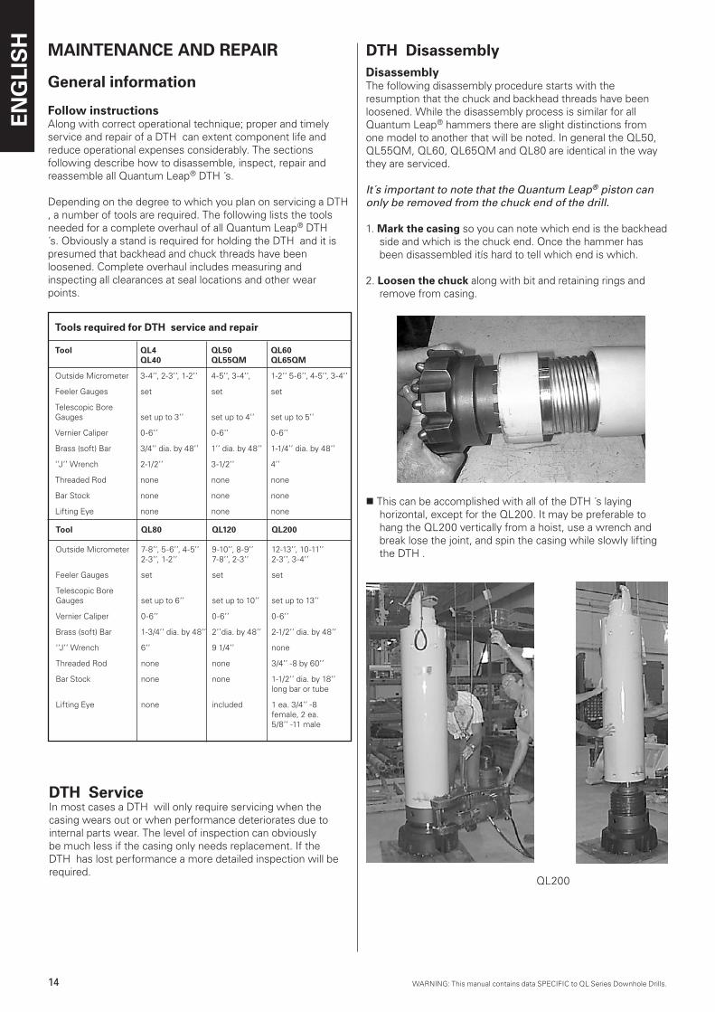
2. Loosen the chuck along with bit and retaining rings and remove from casing.
n This can be accomplished with all of the DTH ´s laying horizontal, except for the QL200. It may be preferable to hang the QL200 vertically from a hoist, use a wrench and break lose the joint, and spin the casing while slowly lifting the DTH .
QL200
DTH Disassembly
WARNING: This manual contains data SPECIFIC to QL Series Downhole Drills.WARNING: This manual contains data SPECIFIC to QL Series Downhole Drills.
ENG
LIS
H
15WARNING: This manual contains data SPECIFIC to QL Series Downhole Drills.
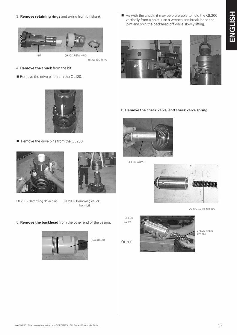
3. Remove retaining rings and o-ring from bit shank.
BIT CHUCK RETAINING
RINGS & O-RING
4. Remove the chuck from the bit.
n Remove the drive pins from the QL120.
n Remove the drive pins from the QL200.
QL200 - Removing drive pins QL200 - Removing chuck from bit
5. Remove the backhead from the other end of the casing.
BACKHEAD
n As with the chuck, it may be preferable to hold the QL200 vertically from a hoist, use a wrench and break loose the joint and spin the backhead off while slowly lifting.
6. Remove the check valve, and check valve spring.
CHECK VALVE
CHECK VALVE SPRING
CHECK
VALVE
CHECK VALVE SPRING
QL200
ENG
LIS
H
16 WARNING: This manual contains data SPECIFIC to QL Series Downhole Drills.WARNING: This manual contains data SPECIFIC to QL Series Downhole Drills.
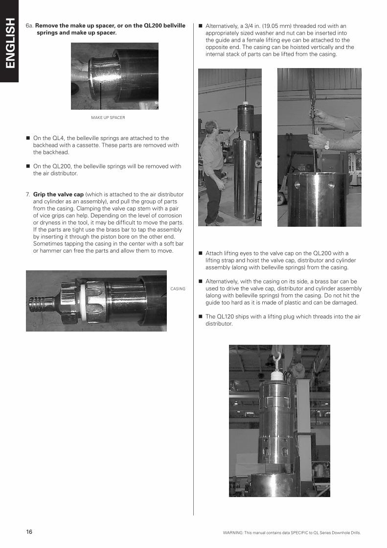
6a. Remove the make up spacer, or on the QL200 bellville springs and make up spacer.
MAKE UP SPACER
n On the QL4, the belleville springs are attached to the backhead with a cassette. These parts are removed with the backhead.
n On the QL200, the belleville springs will be removed with the air distributor.
7. Grip the valve cap (which is attached to the air distributor and cylinder as an assembly), and pull the group of parts from the casing. Clamping the valve cap stem with a pair of vice grips can help. Depending on the level of corrosion or dryness in the tool, it may be difficult to move the parts. If the parts are tight use the brass bar to tap the assembly by inserting it through the piston bore on the other end. Sometimes tapping the casing in the center with a soft bar or hammer can free the parts and allow them to move.
CASING
TM6121 3-6
n Alternatively, a 3/4 in. (19.05 mm) threaded rod with an appropriately sized washer and nut can be inserted into the guide and a female lifting eye can be attached to the opposite end. The casing can be hoisted vertically and the internal stack of parts can be lifted from the casing.
n Attach lifting eyes to the valve cap on the QL200 with a lifting strap and hoist the valve cap, distributor and cylinder assembly (along with belleville springs) from the casing.
n Alternatively, with the casing on its side, a brass bar can be used to drive the valve cap, distributor and cylinder assembly (along with belleville springs) from the casing. Do not hit the guide too hard as it is made of plastic and can be damaged.
n The QL120 ships with a lifting plug which threads into the air distributor.
WARNING: This manual contains data SPECIFIC to QL Series Downhole Drills.WARNING: This manual contains data SPECIFIC to QL Series Downhole Drills.
ENG
LIS
H
17WARNING: This manual contains data SPECIFIC to QL Series Downhole Drills.
CA
SIN
G
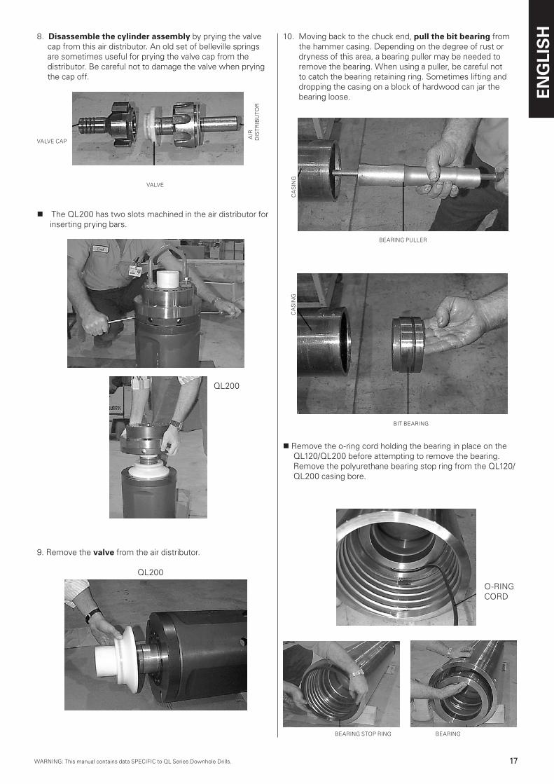
8. Disassemble the cylinder assembly by prying the valve cap from this air distributor. An old set of belleville springs are sometimes useful for prying the valve cap from the distributor. Be careful not to damage the valve when prying the cap off.
VALVE CAP
VALVE
n The QL200 has two slots machined in the air distributor for inserting prying bars.
AIR
D
IST
RIB
UTO
R
9. Remove the valve from the air distributor.
QL200
QL200
10. Moving back to the chuck end, pull the bit bearing from the hammer casing. Depending on the degree of rust or dryness of this area, a bearing puller may be needed to remove the bearing. When using a puller, be careful not to catch the bearing retaining ring. Sometimes lifting and dropping the casing on a block of hardwood can jar the bearing loose.
BIT BEARING
n Remove the o-ring cord holding the bearing in place on the QL120/QL200 before attempting to remove the bearing. Remove the polyurethane bearing stop ring from the QL120/QL200 casing bore.
BEARING PULLER
CA
SIN
G
BEARING STOP RING BEARING
O-RING CORD
ENG
LIS
H
18 WARNING: This manual contains data SPECIFIC to QL Series Downhole Drills.WARNING: This manual contains data SPECIFIC to QL Series Downhole Drills.
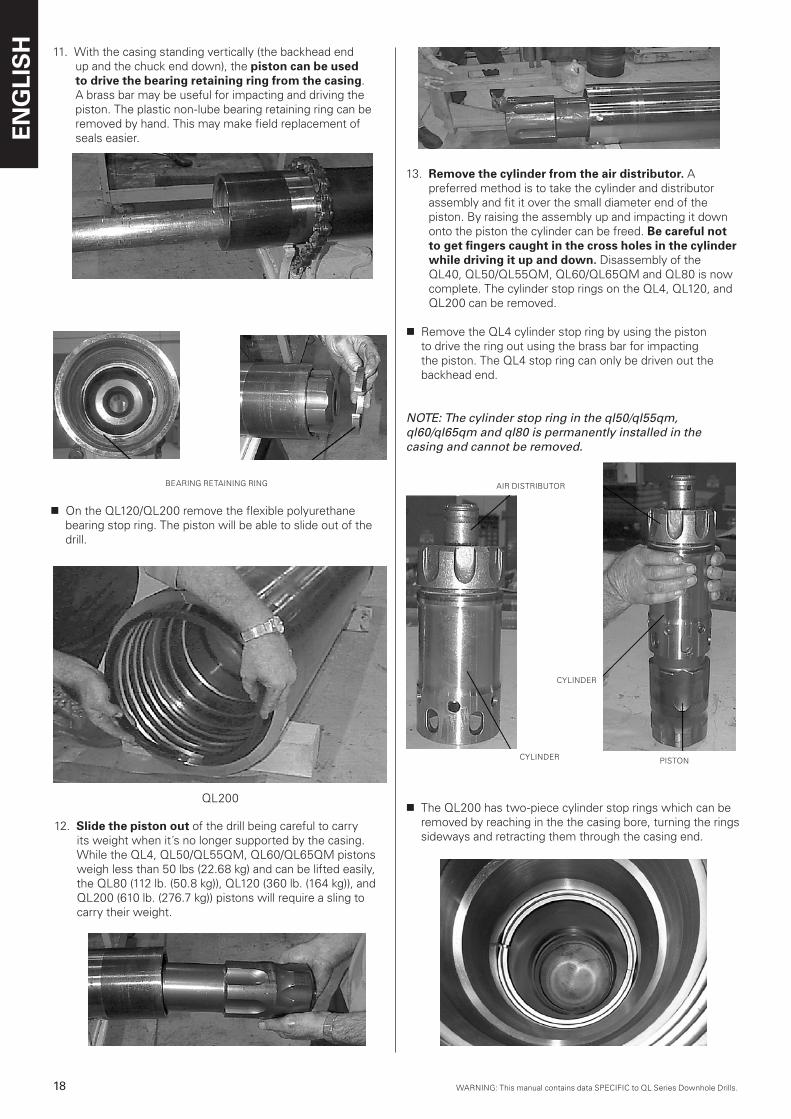
13. Remove the cylinder from the air distributor. A preferred method is to take the cylinder and distributor assembly and fit it over the small diameter end of the piston. By raising the assembly up and impacting it down onto the piston the cylinder can be freed. Be careful not to get fingers caught in the cross holes in the cylinder while driving it up and down. Disassembly of the QL40, QL50/QL55QM, QL60/QL65QM and QL80 is now complete. The cylinder stop rings on the QL4, QL120, and QL200 can be removed.
n Remove the QL4 cylinder stop ring by using the piston to drive the ring out using the brass bar for impacting the piston. The QL4 stop ring can only be driven out the backhead end.
NOTE: The cylinder stop ring in the ql50/ql55qm, ql60/ql65qm and ql80 is permanently installed in the casing and cannot be removed.
11. With the casing standing vertically (the backhead end up and the chuck end down), the piston can be used to drive the bearing retaining ring from the casing. A brass bar may be useful for impacting and driving the piston. The plastic non-lube bearing retaining ring can be removed by hand. This may make field replacement of seals easier.
BEARING RETAINING RING
n On the QL120/QL200 remove the flexible polyurethane bearing stop ring. The piston will be able to slide out of the drill.
QL200
12. Slide the piston out of the drill being careful to carry its weight when it´s no longer supported by the casing. While the QL4, QL50/QL55QM, QL60/QL65QM pistons weigh less than 50 lbs (22.68 kg) and can be lifted easily, the QL80 (112 lb. (50.8 kg)), QL120 (360 lb. (164 kg)), and QL200 (610 lb. (276.7 kg)) pistons will require a sling to carry their weight.
QL200
AIR DISTRIBUTOR
CYLINDER
PISTON
n The QL200 has two-piece cylinder stop rings which can be removed by reaching in the the casing bore, turning the rings sideways and retracting them through the casing end.
CYLINDER
WARNING: This manual contains data SPECIFIC to QL Series Downhole Drills.WARNING: This manual contains data SPECIFIC to QL Series Downhole Drills.
ENG
LIS
H
19WARNING: This manual contains data SPECIFIC to QL Series Downhole Drills.
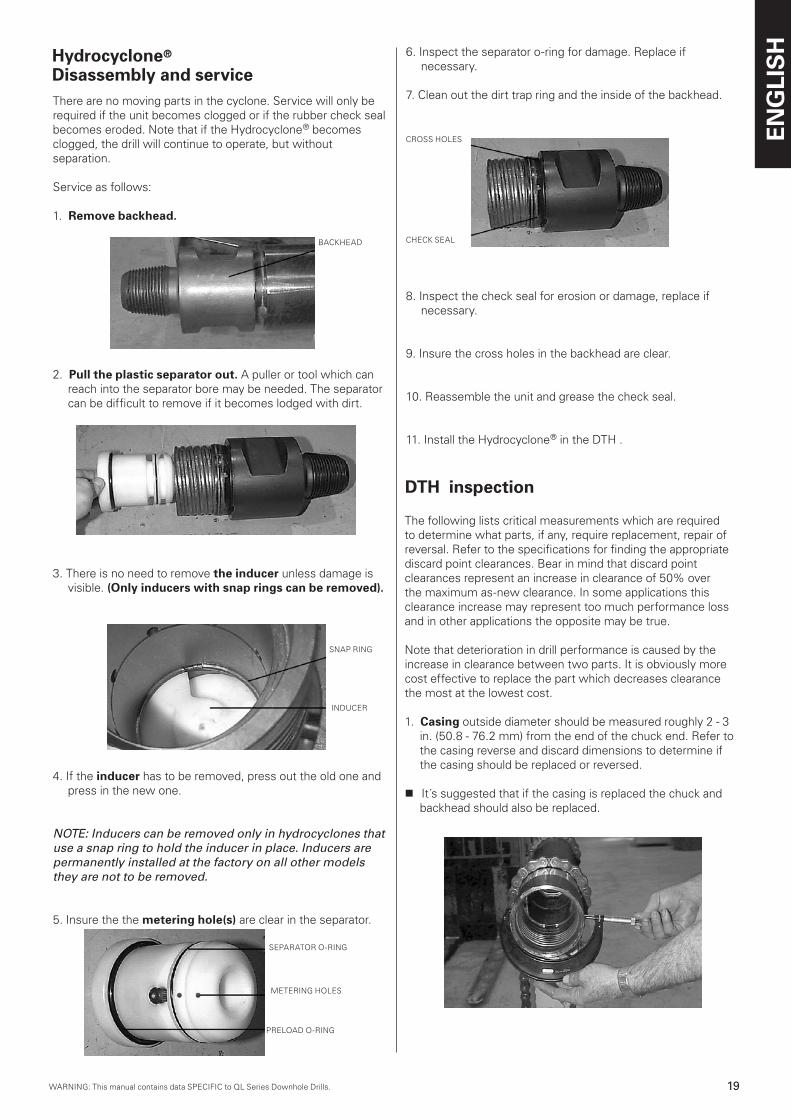
There are no moving parts in the cyclone. Service will only be required if the unit becomes clogged or if the rubber check seal becomes eroded. Note that if the Hydrocyclone® becomesclogged, the drill will continue to operate, but without separation.
Service as follows:
1. Remove backhead.
Hydrocyclone® Disassembly and service
2. Pull the plastic separator out. A puller or tool which can reach into the separator bore may be needed. The separator can be difficult to remove if it becomes lodged with dirt.
3. There is no need to remove the inducer unless damage is visible. (Only inducers with snap rings can be removed).
4. If the inducer has to be removed, press out the old one and press in the new one.
NOTE: Inducers can be removed only in hydrocyclones that use a snap ring to hold the inducer in place. Inducers are permanently installed at the factory on all other models they are not to be removed.
5. Insure the the metering hole(s) are clear in the separator.
BACKHEAD
INDUCER
SNAP RING
6. Inspect the separator o-ring for damage. Replace if necessary.
7. Clean out the dirt trap ring and the inside of the backhead.
CROSS HOLES
CHECK SEAL
8. Inspect the check seal for erosion or damage, replace if necessary.
9. Insure the cross holes in the backhead are clear.
10. Reassemble the unit and grease the check seal.
11. Install the Hydrocyclone® in the DTH .
PRELOAD O-RING
SEPARATOR O-RING
METERING HOLES
The following lists critical measurements which are required to determine what parts, if any, require replacement, repair of reversal. Refer to the specifications for finding the appropriatediscard point clearances. Bear in mind that discard point clearances represent an increase in clearance of 50% over the maximum as-new clearance. In some applications this clearance increase may represent too much performance loss and in other applications the opposite may be true.
Note that deterioration in drill performance is caused by the increase in clearance between two parts. It is obviously more cost effective to replace the part which decreases clearancethe most at the lowest cost.
1. Casing outside diameter should be measured roughly 2 - 3 in. (50.8 - 76.2 mm) from the end of the chuck end. Refer to the casing reverse and discard dimensions to determine if the casing should be replaced or reversed.
n It´s suggested that if the casing is replaced the chuck and backhead should also be replaced.
DTH inspection
ENG
LIS
H
20 WARNING: This manual contains data SPECIFIC to QL Series Downhole Drills.WARNING: This manual contains data SPECIFIC to QL Series Downhole Drills.
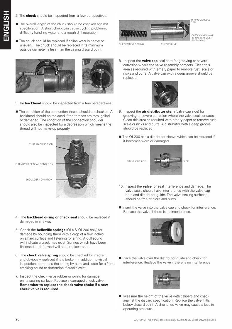
CHECK VALVE SPRING CHECK VALVE
8. Inspect the valve cap seal bore for grooving or severe corrosion where the valve assembly contacts. Clean this area as required with emery paper to remove rust, scale or nicks and burrs. A valve cap with a deep groove should be replaced.
9. Inspect the air distributor stem (valve cap side) for grooving or severe corrosion where the valve seal contacts. Clean this area as required with emery paper to remove rust, scale or nicks and burrs. A distributor with a deep groove should be replaced.
n The QL200 has a distributor sleeve which can be replaced if it becomes worn or damaged.
VALVE CAP SIDE CYLINDER SIDE
10. Inspect the valve for seal interference and damage. The valve seals should have interference with the valve cap bore and distributor guide. The valve sealing surfaces should be free of nicks and burrs.
n Insert the valve into the valve cap and check for interference. Replace the valve if there is no interference.
n Place the valve over the distributor guide and check for interference. Replace the valve if there is no interference.
n Measure the height of the valve with calipers and check against the discard specification. Replace the valve if itís below discard point. A shortened valve may cause a loss in operating pressure.
2. The chuck should be inspected from a few perspectives:
n The overall length of the chuck should be checked against specification. A short chuck can cause cycling problems, difficulty handling water and a rough drill operation.
n The chuck should be replaced if spline wear is heavy or uneven.. The chuck should be replaced if its minimum outside diameter is less than the casing discard point.
3.The backhead should be inspected from a few perspectives:
n The condition of the connection thread should be checked. A backhead should be replaced if the threads are torn, galled or damaged. The condition of the connection shoulder should also be inspected for a depression which means the thread will not make-up properly.
THREAD CONDITION
O-RING/CHECK SEAL CONDITION
SHOULDER CONDITION
4. The backhead o-ring or check seal should be replaced if damaged in any way.
5. Check the belleville springs (QL4 & QL200 only) for damage by bouncing them with a drop of a few inches on a hard surface and listening for a ring. A dull sound will indicate a crack may exist. Springs which have been flattened or deformed will need replacement.
6. The check valve spring should be checked for cracks and obviously replaced if it is broken. In addition to visual inspection, compress the spring by hand and listen for a faint cracking sound to determine if cracks exist.
7. Inspect the check valve rubber or o-ring for damage on its sealing surface. Replace a damaged check valve. Remember to replace the check valve choke if a new check valve is required.
CHECK VALVE CHOKE(CHOKE FLAT MUST FACE DOWN)
O-RING/MOULDED SEAL
WARNING: This manual contains data SPECIFIC to QL Series Downhole Drills.WARNING: This manual contains data SPECIFIC to QL Series Downhole Drills.
ENG
LIS
H
21WARNING: This manual contains data SPECIFIC to QL Series Downhole Drills.
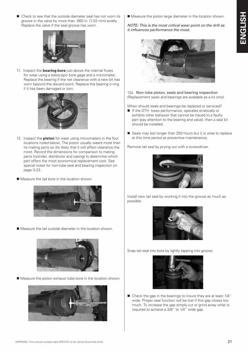
n Check to see that the outside diameter seal has not worn its groove in the valve by more than .060 in. (1.52 mm) axially. Replace the valve if the seal groove has worn.
11. Inspect the bearing bore just above the internal flutes for wear using a telescopic bore gage and a micrometer. Replace the bearing if the net clearance with a new bit has worn beyond the discard point. Replace the bearing o-ring if it has been damaged or torn.
12. Inspect the piston for wear using micrometers in the four locations noted below. The piston usually wears more than its mating parts so itís likely that it will affect clearance the most. Record the dimensions for comparison to mating parts (cylinder, distributor and casing) to determine which part offers the most economical replacement cost. See special notes for non-lube seal and bearing inspection on page 3-23.
n Measure the tail bore in the location shown.
n Measure the tail outside diameter in the location shown.
n Measure the piston exhaust tube bore in the location shown.
n Measure the piston large diameter in the location shown.
NOTE: This is the most critical wear point on the drill as it influences performance the most.
12a Non-lube piston, seals and bearing inspection(Replacement seals and bearings are available as a kit only)
When should seals and bearings be replaced or serviced?n If the DTH loses performance, operates erratically or
exhibits other behavior that cannot be traced to a faulty part (pay attention to the bearing and valve), then a seal kit should be installed.
n Seals may last longer than 250 hours but it is wise to replace at this time period as preventive maintenance.
Remove tail seal by prying out with a screwdriver.
Install new tail seal by working it into the groove as much as possible.
Snap tail seal into bore by lightly tapping into groove.
n Check the gap in the bearings to insure they are at least 1/4’’ wide. Proper seal function will be lost if this gap closes too much. To increase the gap simply cut or grind away what is required to achieve a 3/8’’ to 1/4’’ wide gap.
ENG
LIS
H
22 WARNING: This manual contains data SPECIFIC to QL Series Downhole Drills.WARNING: This manual contains data SPECIFIC to QL Series Downhole Drills.
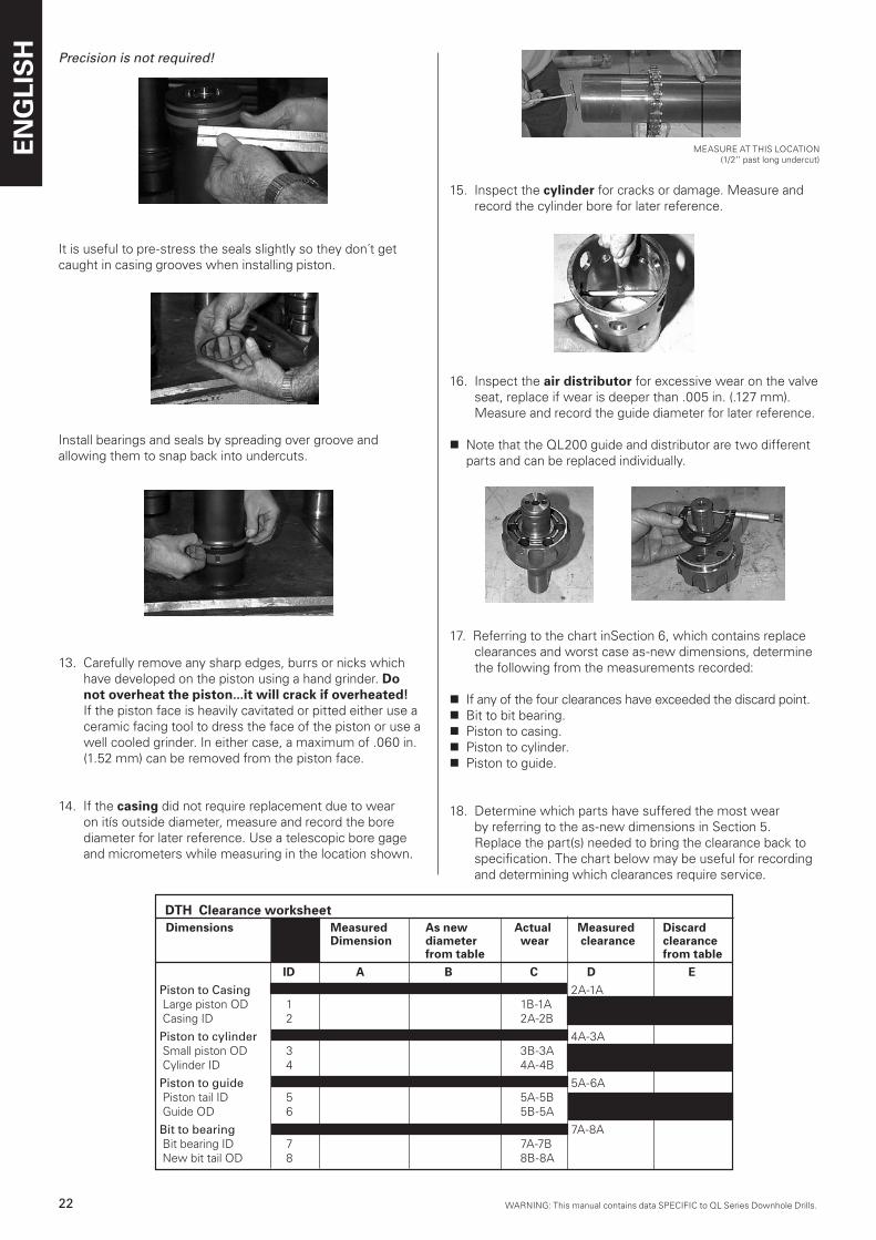
Precision is not required!
It is useful to pre-stress the seals slightly so they don´t get caught in casing grooves when installing piston.
Install bearings and seals by spreading over groove and allowing them to snap back into undercuts.
13. Carefully remove any sharp edges, burrs or nicks which have developed on the piston using a hand grinder. Do not overheat the piston...it will crack if overheated! If the piston face is heavily cavitated or pitted either use a ceramic facing tool to dress the face of the piston or use a well cooled grinder. In either case, a maximum of .060 in. (1.52 mm) can be removed from the piston face.
14. If the casing did not require replacement due to wear on itís outside diameter, measure and record the bore diameter for later reference. Use a telescopic bore gage and micrometers while measuring in the location shown.
MEASURE AT THIS LOCATION(1/2’’ past long undercut)
15. Inspect the cylinder for cracks or damage. Measure and record the cylinder bore for later reference.
16. Inspect the air distributor for excessive wear on the valve seat, replace if wear is deeper than .005 in. (.127 mm). Measure and record the guide diameter for later reference.
n Note that the QL200 guide and distributor are two different parts and can be replaced individually.
17. Referring to the chart inSection 6, which contains replace clearances and worst case as-new dimensions, determine the following from the measurements recorded:
n If any of the four clearances have exceeded the discard point.n Bit to bit bearing.n Piston to casing.n Piston to cylinder.n Piston to guide.
18. Determine which parts have suffered the most wear by referring to the as-new dimensions in Section 5. Replace the part(s) needed to bring the clearance back to specification. The chart below may be useful for recording and determining which clearances require service.
DTH Clearance worksheet Dimensions Measured As new Actual Measured Discard Dimension diameter wear clearance clearance from table from table ID A B C D E Piston to Casing 2A-1A Large piston OD 1 1B-1A Casing ID 2 2A-2B
Piston to cylinder 4A-3A Small piston OD 3 3B-3A Cylinder ID 4 4A-4B
Piston to guide 5A-6A Piston tail ID 5 5A-5B Guide OD 6 5B-5A
Bit to bearing 7A-8A Bit bearing ID 7 7A-7B New bit tail OD 8 8B-8A
WARNING: This manual contains data SPECIFIC to QL Series Downhole Drills.WARNING: This manual contains data SPECIFIC to QL Series Downhole Drills.
ENG
LIS
H
2�WARNING: This manual contains data SPECIFIC to QL Series Downhole Drills.
The DTH assembly process is identical to the disassembly process yet in reverse.The following guidelines should be used:
n All parts should be clean and free of grit dirt and other foreign material.
n All nicks and burrs on parts should have been removed.
n All parts should be coated with rockdrill oil and preferably the same type to be used on the drilling rig
n All damaged o-rings should have been replaced if. All seals should be oiled or greased to avoid cutting or tearing.
n If corrosion is common it may be useful to spray the threads on the casing with a corrosion protector such as LPS Hardcoat or an equivalent. Make sure the threads are clean and dry and sufficient drying time is allowed.
1. Reassemble the air distributor, valve and valve cap assembly. Remember that the air distributor and valve cap o-rings ‘’lock’’ the parts together for ease of assembly and disassembly:
VALVE CAP
n With the cylinder resting on a piece of wood or hard rubber, place the air distributor (insure o-ring is installed) on the cylinder and drive it into the cylinder bore. Use a mallet or brass bar to overcome the o-ring pressure.
n Insure the valve cap o-ring is installed in the valve cap and that itís in good condition.
n Install the valve into the valve cap being careful not to fold or tear the valve seal.
n Slide the valve and valve cap onto the distributor stem, again being careful not to damage the valve seal. Tap the top of the valve cap with a mallet to seat the o-ring and lock the parts together.
QL200
DTH assembly
AIR DISTRIBUTOR
VALVE
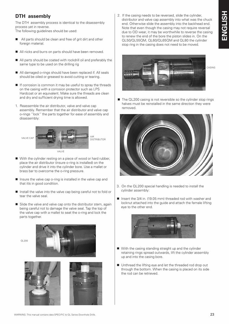
2. If the casing needs to be reversed, slide the cylinder, distributor and valve cap assembly into what was the chuck end. Otherwise slide the assembly into the backhead end. Note that even though the casing may not require reversal due to OD wear, it may be worthwhile to reverse the casing to renew the end of the bore the piston slides in. On the QL50/QL55QM, QL60/QL65QM and QL80 the cylinder stop ring in the casing does not need to be moved.
CASING
n The QL200 casing is not reversible so the cylinder stop rings halves must be reinstalled in the same direction they were removed.
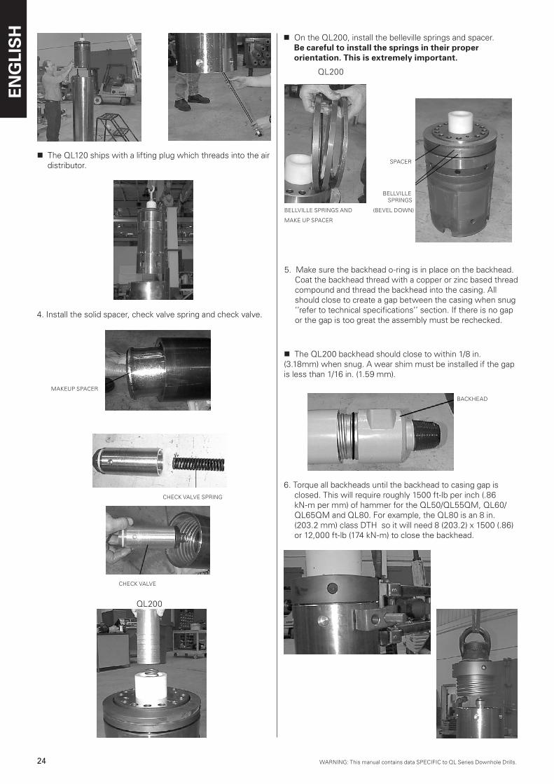
3. On the QL200 special handling is needed to install the cylinder assembly:
n Insert the 3/4 in. (19.05 mm) threaded rod with washer and locknut attached into the guide and attach the female lifting eye to the other end.
n With the casing standing straight up and the cylinder retaining rings spread outwards, lift the cylinder assembly up and into the casing bore.
n Unthread the lifting eye and let the threaded rod drop out through the bottom. When the casing is placed on its side the rod can be retrieved.
QL200
ENG
LIS
H
24 WARNING: This manual contains data SPECIFIC to QL Series Downhole Drills.WARNING: This manual contains data SPECIFIC to QL Series Downhole Drills.
n The QL120 ships with a lifting plug which threads into the air distributor.
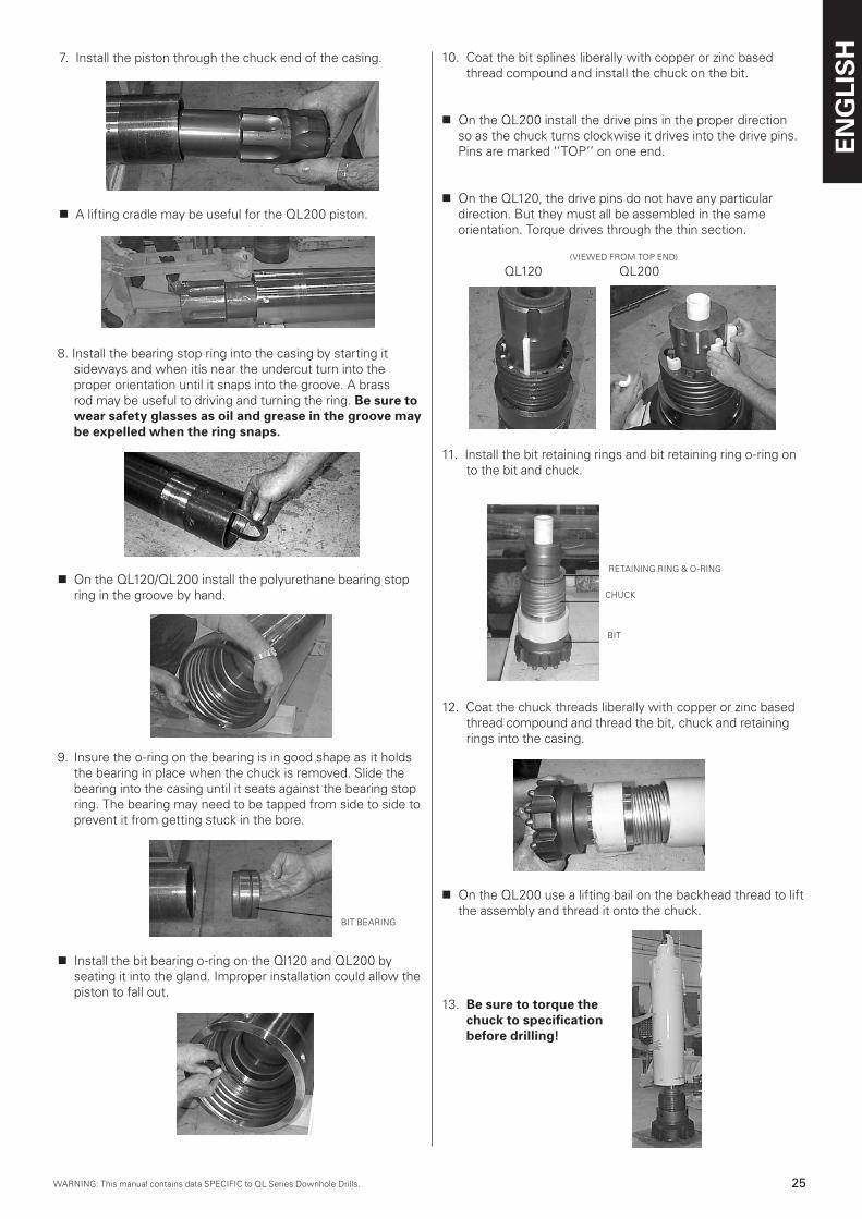
4. Install the solid spacer, check valve spring and check valve.
n On the QL200, install the belleville springs and spacer. Be careful to install the springs in their proper orientation. This is extremely important.
MAKEUP SPACER
CHECK VALVE
CHECK VALVE SPRING
QL200
QL200
BELLVILLE SPRINGS
BELLVILLE SPRINGS AND (BEVEL DOWN)
MAKE UP SPACER
5. Make sure the backhead o-ring is in place on the backhead. Coat the backhead thread with a copper or zinc based thread compound and thread the backhead into the casing. All should close to create a gap between the casing when snug ‘’refer to technical specifications’’ section. If there is no gap or the gap is too great the assembly must be rechecked.
SPACER
n The QL200 backhead should close to within 1/8 in. (3.18mm) when snug. A wear shim must be installed if the gap is less than 1/16 in. (1.59 mm).
6. Torque all backheads until the backhead to casing gap is closed. This will require roughly 1500 ft-lb per inch (.86 kN-m per mm) of hammer for the QL50/QL55QM, QL60/QL65QM and QL80. For example, the QL80 is an 8 in. (203.2 mm) class DTH so it will need 8 (203.2) x 1500 (.86) or 12,000 ft-lb (174 kN-m) to close the backhead.
QL200
BACKHEAD
WARNING: This manual contains data SPECIFIC to QL Series Downhole Drills.WARNING: This manual contains data SPECIFIC to QL Series Downhole Drills.
ENG
LIS
H
25WARNING: This manual contains data SPECIFIC to QL Series Downhole Drills.
BACKHEAD
11. Install the bit retaining rings and bit retaining ring o-ring on to the bit and chuck.
RETAINING RING & O-RING
CHUCK
BIT
12. Coat the chuck threads liberally with copper or zinc based thread compound and thread the bit, chuck and retaining rings into the casing.
n On the QL200 use a lifting bail on the backhead thread to lift the assembly and thread it onto the chuck.
13. Be sure to torque the chuck to specification before drilling!
9. Insure the o-ring on the bearing is in good shape as it holds the bearing in place when the chuck is removed. Slide the bearing into the casing until it seats against the bearing stop ring. The bearing may need to be tapped from side to side to prevent it from getting stuck in the bore.
n Install the bit bearing o-ring on the Ql120 and QL200 by seating it into the gland. Improper installation could allow the piston to fall out.
7. Install the piston through the chuck end of the casing.
n A lifting cradle may be useful for the QL200 piston.
QL200
8. Install the bearing stop ring into the casing by starting it sideways and when itís near the undercut turn into the proper orientation until it snaps into the groove. A brass rod may be useful to driving and turning the ring. Be sure to wear safety glasses as oil and grease in the groove may be expelled when the ring snaps.
n On the QL120/QL200 install the polyurethane bearing stop ring in the groove by hand.
10. Coat the bit splines liberally with copper or zinc based thread compound and install the chuck on the bit.
n On the QL200 install the drive pins in the proper direction so as the chuck turns clockwise it drives into the drive pins. Pins are marked ‘’TOP’’ on one end.
n On the QL120, the drive pins do not have any particular direction. But they must all be assembled in the same orientation. Torque drives through the thin section.
(VIEWED FROM TOP END)
QL120 QL200
BIT BEARING
ENG
LIS
H
26 WARNING: This manual contains data SPECIFIC to QL Series Downhole Drills.WARNING: This manual contains data SPECIFIC to QL Series Downhole Drills.
Exhaust tubes (footvalves) can become damaged during handling or physically eroded while in service, the net result is that they need to be serviced from time to time.
Tube failures will generally occur due to erosion caused by the jetting of water, oil and grit which is displaced as the piston strikes the bit. This form of failure is common in waterwell applications where injection rates are high. This high velocity jet of material actually erodes away the base of the tube and can eventually cause the tube to fail. Tube erosion can be reduced by insuring water is clean and free from particulate matter and that excessive fluid injection is avoided. It´s a good idea to monitor tube erosion and make replacements as needed before a hole is started to avoid a costly trip out of the hole.
Exhaust tubes can be removed by cutting off the remaining portion of the tube and prying the remaining piece out with a screwdriver. It may be useful to use a small rotary file to relieve the bore of the tube which remains in the bit. However, be careful not to touch the bit tube bore with the rotary file or a heat check followed by bit failure may result. The tube can also be heated slightly to soften the plastic. Avoid breathing fumes which may come from the heated plastic and also be careful not to overheat the bit.
A new exhaust tube can be installed by driving the tube into the bit with a rubber faced mallet or with a block of wood between the hammer and tube. Do not hit the tube directly with a metalhammer or the tube may be damaged. Alternatively, the tube can be pressed into the bore using a press or even the table and feed on a drilling rig. Be careful not to over-press the tube.
Exhaust tube replacement and installation
Bits
SelectionProper selection of the correct bit type along with good service practice can reduce operating costs and improve production considerably. The sections following will assist you with the bit selection process and provide instruction for service practice.
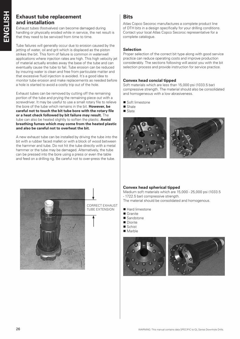
Convex head concial tipped Soft materials which are less than 15,000 psi (1033.5 bar) compressive strength. The material should also be consolidated and homogeneous with a low abrasiveness.
n Soft limestonen Shalen Slate
CORRECT EXHAUSTTUBE EXTENSION
Convex head spherical tipped Medium soft materials which are 15,000 - 25,000 psi (1033.5 - 1722.5 bar) compressive strength. The material should be consolidated and homogenous.
n Hard limestonen Graniten Sandstonen Dioriten Schistn Marble
Atlas Copco Secoroc manufactures a complete product line of DTH bits in a design specifically for your drilling conditions. Contact your local Atlas Copco Secoroc representative for a complete catalogue.
WARNING: This manual contains data SPECIFIC to QL Series Downhole Drills.WARNING: This manual contains data SPECIFIC to QL Series Downhole Drills.
ENG
LIS
H
27WARNING: This manual contains data SPECIFIC to QL Series Downhole Drills.
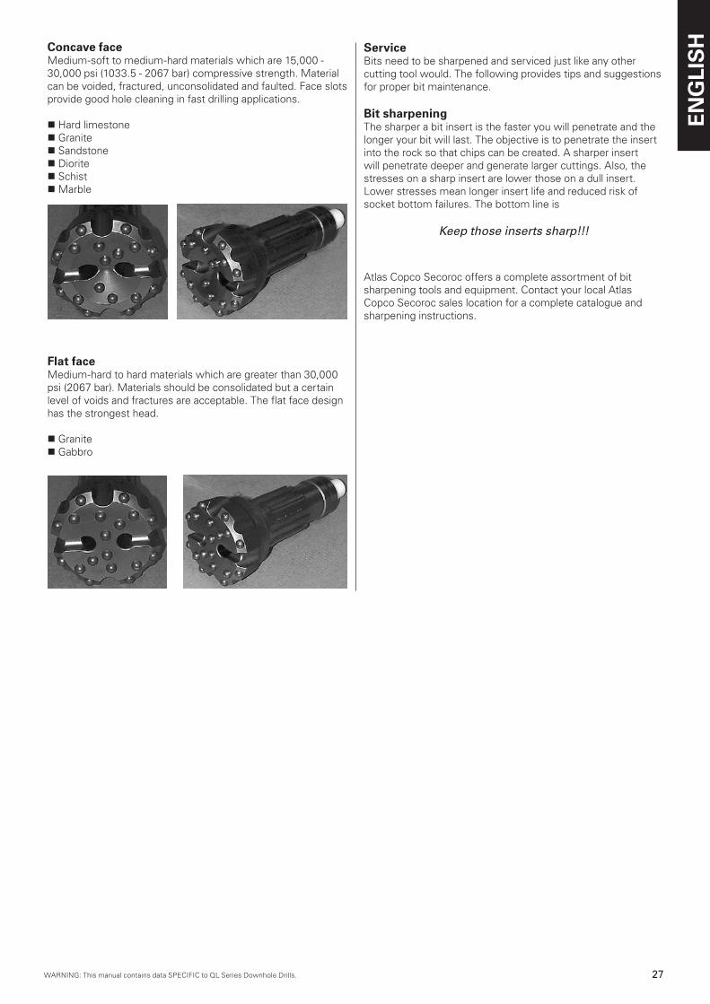
Concave face Medium-soft to medium-hard materials which are 15,000 - 30,000 psi (1033.5 - 2067 bar) compressive strength. Material can be voided, fractured, unconsolidated and faulted. Face slotsprovide good hole cleaning in fast drilling applications.
n Hard limestonen Graniten Sandstonen Dioriten Schistn Marble
Flat face Medium-hard to hard materials which are greater than 30,000 psi (2067 bar). Materials should be consolidated but a certain level of voids and fractures are acceptable. The flat face designhas the strongest head.
n Graniten Gabbro
ServiceBits need to be sharpened and serviced just like any other cutting tool would. The following provides tips and suggestions for proper bit maintenance.
Bit sharpeningThe sharper a bit insert is the faster you will penetrate and the longer your bit will last. The objective is to penetrate the insert into the rock so that chips can be created. A sharper insertwill penetrate deeper and generate larger cuttings. Also, the stresses on a sharp insert are lower those on a dull insert. Lower stresses mean longer insert life and reduced risk of socket bottom failures. The bottom line is
Keep those inserts sharp!!!
Atlas Copco Secoroc offers a complete assortment of bit sharpening tools and equipment. Contact your local Atlas Copco Secoroc sales location for a complete catalogue and sharpening instructions.
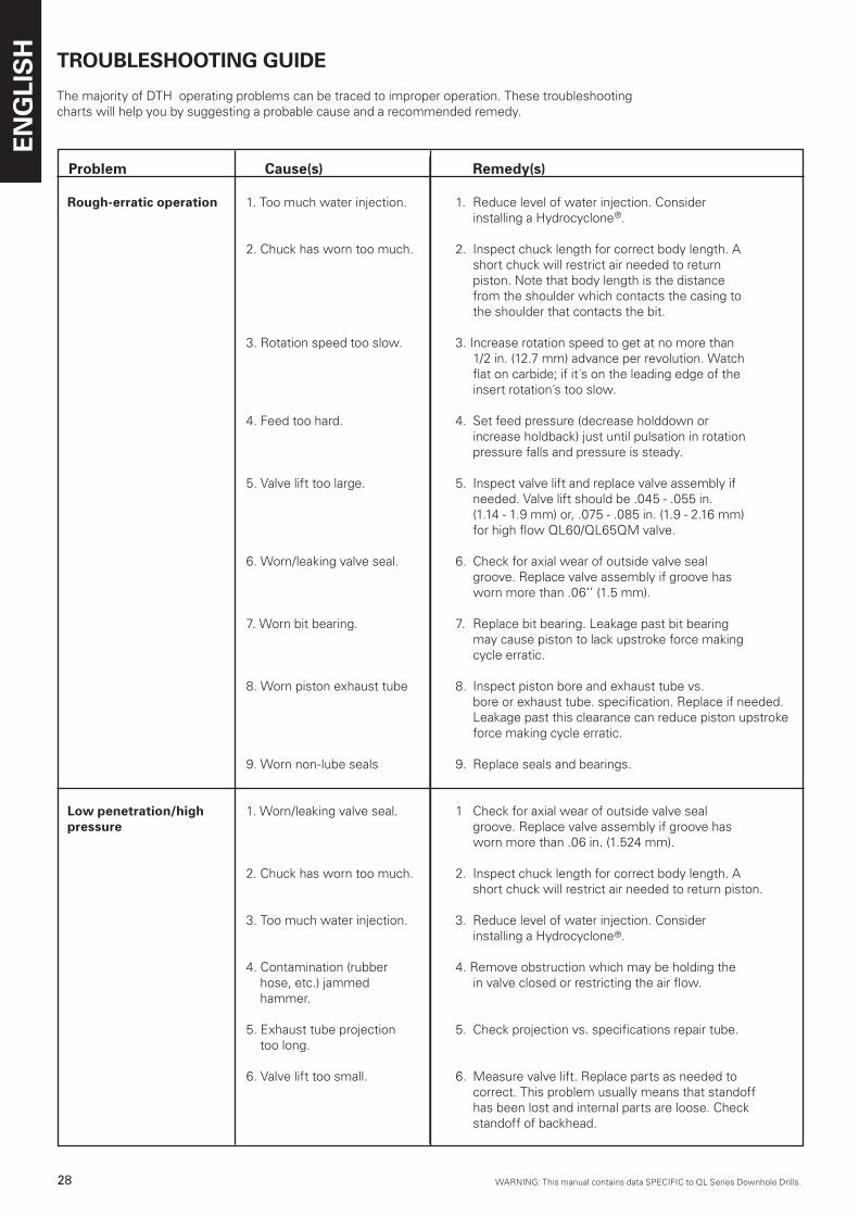
ENG
LIS
H
28 WARNING: This manual contains data SPECIFIC to QL Series Downhole Drills.WARNING: This manual contains data SPECIFIC to QL Series Downhole Drills.
TROUBLESHOOTING GUIDE
The majority of DTH operating problems can be traced to improper operation. These troubleshootingcharts will help you by suggesting a probable cause and a recommended remedy.
Problem Cause(s) Remedy(s)
Rough-erratic operation 1. Too much water injection. 1. Reduce level of water injection. Consider installing a Hydrocyclone®.
2. Chuck has worn too much. 2. Inspect chuck length for correct body length. A short chuck will restrict air needed to return piston. Note that body length is the distance from the shoulder which contacts the casing to the shoulder that contacts the bit.
3. Rotation speed too slow. 3. Increase rotation speed to get at no more than 1/2 in. (12.7 mm) advance per revolution. Watch flat on carbide; if it´s on the leading edge of the insert rotation´s too slow.
4. Feed too hard. 4. Set feed pressure (decrease holddown or increase holdback) just until pulsation in rotation pressure falls and pressure is steady.
5. Valve lift too large. 5. Inspect valve lift and replace valve assembly if needed. Valve lift should be .045 - .055 in. (1.14 - 1.9 mm) or, .075 - .085 in. (1.9 - 2.16 mm) for high flow QL60/QL65QM valve.
6. Worn/leaking valve seal. 6. Check for axial wear of outside valve seal groove. Replace valve assembly if groove has worn more than .06’’ (1.5 mm).
7. Worn bit bearing. 7. Replace bit bearing. Leakage past bit bearing may cause piston to lack upstroke force making cycle erratic.
8. Worn piston exhaust tube 8. Inspect piston bore and exhaust tube vs. bore or exhaust tube. specification. Replace if needed. Leakage past this clearance can reduce piston upstroke force making cycle erratic.
9. Worn non-lube seals 9. Replace seals and bearings.
Low penetration/high 1. Worn/leaking valve seal. 1 Check for axial wear of outside valve seal pressure groove. Replace valve assembly if groove has worn more than .06 in. (1.524 mm).
2. Chuck has worn too much. 2. Inspect chuck length for correct body length. A short chuck will restrict air needed to return piston.
3. Too much water injection. 3. Reduce level of water injection. Consider installing a Hydrocyclone®.
4. Contamination (rubber 4. Remove obstruction which may be holding the hose, etc.) jammed in valve closed or restricting the air flow. hammer.
5. Exhaust tube projection 5. Check projection vs. specifications repair tube. too long.
6. Valve lift too small. 6. Measure valve lift. Replace parts as needed to correct. This problem usually means that standoff has been lost and internal parts are loose. Check standoff of backhead.
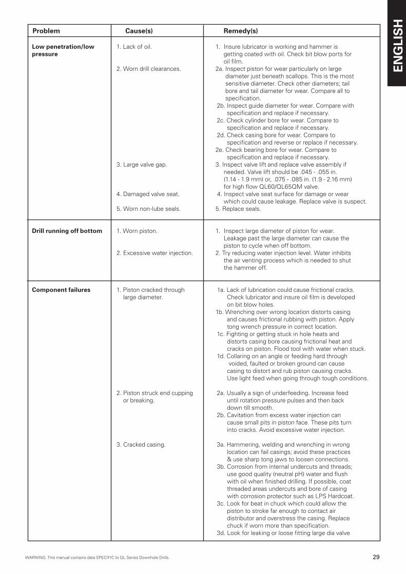
WARNING: This manual contains data SPECIFIC to QL Series Downhole Drills.WARNING: This manual contains data SPECIFIC to QL Series Downhole Drills.
ENG
LIS
H
29WARNING: This manual contains data SPECIFIC to QL Series Downhole Drills.
Problem Cause(s) Remedy(s)
Low penetration/low 1. Lack of oil. 1. Insure lubricator is working and hammer is pressure getting coated with oil. Check bit blow ports for oil film. 2. Worn drill clearances. 2a. Inspect piston for wear particularly on large diameter just beneath scallops. This is the most sensitive diameter. Check other diameters; tail bore and tail diameter for wear. Compare all to specification. 2b. Inspect guide diameter for wear. Compare with specification and replace if necessary. 2c. Check cylinder bore for wear. Compare to specification and replace if necessary. 2d. Check casing bore for wear. Compare to specification and reverse or replace if necessary. 2e. Check bearing bore for wear. Compare to specification and replace if necessary. 3. Large valve gap. 3. Inspect valve lift and replace valve assembly if needed. Valve lift should be .045 - .055 in. (1.14 - 1.9 mm) or, .075 - .085 in. (1.9 - 2.16 mm) for high flow QL60/QL65QM valve. 4. Damaged valve seat. 4. Inspect valve seat surface for damage or wear which could cause leakage. Replace valve is suspect. 5. Worn non-lube seals. 5. Replace seals.
Drill running off bottom 1. Worn piston. 1. Inspect large diameter of piston for wear. Leakage past the large diameter can cause the piston to cycle when off bottom. 2. Excessive water injection. 2. Try reducing water injection level. Water inhibits the air venting process which is needed to shut the hammer off.
Component failures 1. Piston cracked through 1a. Lack of lubrication could cause frictional cracks. large diameter. Check lubricator and insure oil film is developed on bit blow holes. 1b. Wrenching over wrong location distorts casing and causes frictional rubbing with piston. Apply tong wrench pressure in correct location. 1c. Fighting or getting stuck in hole heats and distorts casing bore causing frictional heat and cracks on piston. Flood tool with water when stuck. 1d. Collaring on an angle or feeding hard through voided, faulted or broken ground can cause casing to distort and rub piston causing cracks. Use light feed when going through tough conditions.
2. Piston struck end cupping 2a. Usually a sign of underfeeding. Increase feed or breaking. until rotation pressure pulses and then back down till smooth. 2b. Cavitation from excess water injection can cause small pits in piston face. These pits turn into cracks. Avoid excessive water injection.
3. Cracked casing. 3a. Hammering, welding and wrenching in wrong location can fail casings; avoid these practices & use sharp tong jaws to loosen connections. 3b. Corrosion from internal undercuts and threads; use good quality (neutral pH) water and flush with oil when finished drilling. If possible, coat threaded areas undercuts and bore of casing with corrosion protector such as LPS Hardcoat. 3c. Look for beat in chuck which could allow the piston to stroke far enough to contact air distributor and overstress the casing. Replace chuck if worn more than specification. 3d. Look for leaking or loose fitting large dia valve
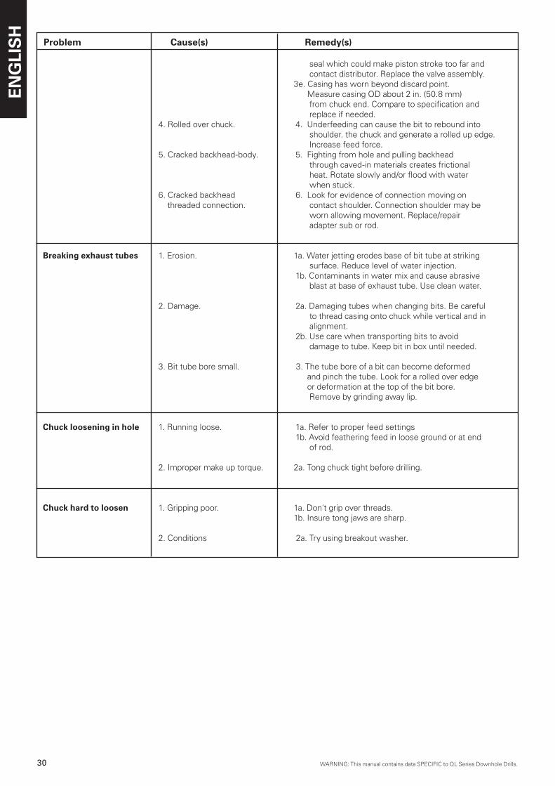
ENG
LIS
H
�0 WARNING: This manual contains data SPECIFIC to QL Series Downhole Drills.WARNING: This manual contains data SPECIFIC to QL Series Downhole Drills.
Problem Cause(s) Remedy(s)
seal which could make piston stroke too far and contact distributor. Replace the valve assembly. 3e. Casing has worn beyond discard point. Measure casing OD about 2 in. (50.8 mm) from chuck end. Compare to specification and replace if needed. 4. Rolled over chuck. 4. Underfeeding can cause the bit to rebound into shoulder. the chuck and generate a rolled up edge. Increase feed force. 5. Cracked backhead-body. 5. Fighting from hole and pulling backhead through caved-in materials creates frictional heat. Rotate slowly and/or flood with water when stuck. 6. Cracked backhead 6. Look for evidence of connection moving on threaded connection. contact shoulder. Connection shoulder may be worn allowing movement. Replace/repair adapter sub or rod.
Breaking exhaust tubes 1. Erosion. 1a. Water jetting erodes base of bit tube at striking surface. Reduce level of water injection. 1b. Contaminants in water mix and cause abrasive blast at base of exhaust tube. Use clean water.
2. Damage. 2a. Damaging tubes when changing bits. Be careful to thread casing onto chuck while vertical and in alignment. 2b. Use care when transporting bits to avoid damage to tube. Keep bit in box until needed.
3. Bit tube bore small. 3. The tube bore of a bit can become deformed and pinch the tube. Look for a rolled over edge or deformation at the top of the bit bore. Remove by grinding away lip.
Chuck loosening in hole 1. Running loose. 1a. Refer to proper feed settings 1b. Avoid feathering feed in loose ground or at end of rod.
2. Improper make up torque. 2a. Tong chuck tight before drilling.
Chuck hard to loosen 1. Gripping poor. 1a. Don´t grip over threads. 1b. Insure tong jaws are sharp.
2. Conditions 2a. Try using breakout washer.
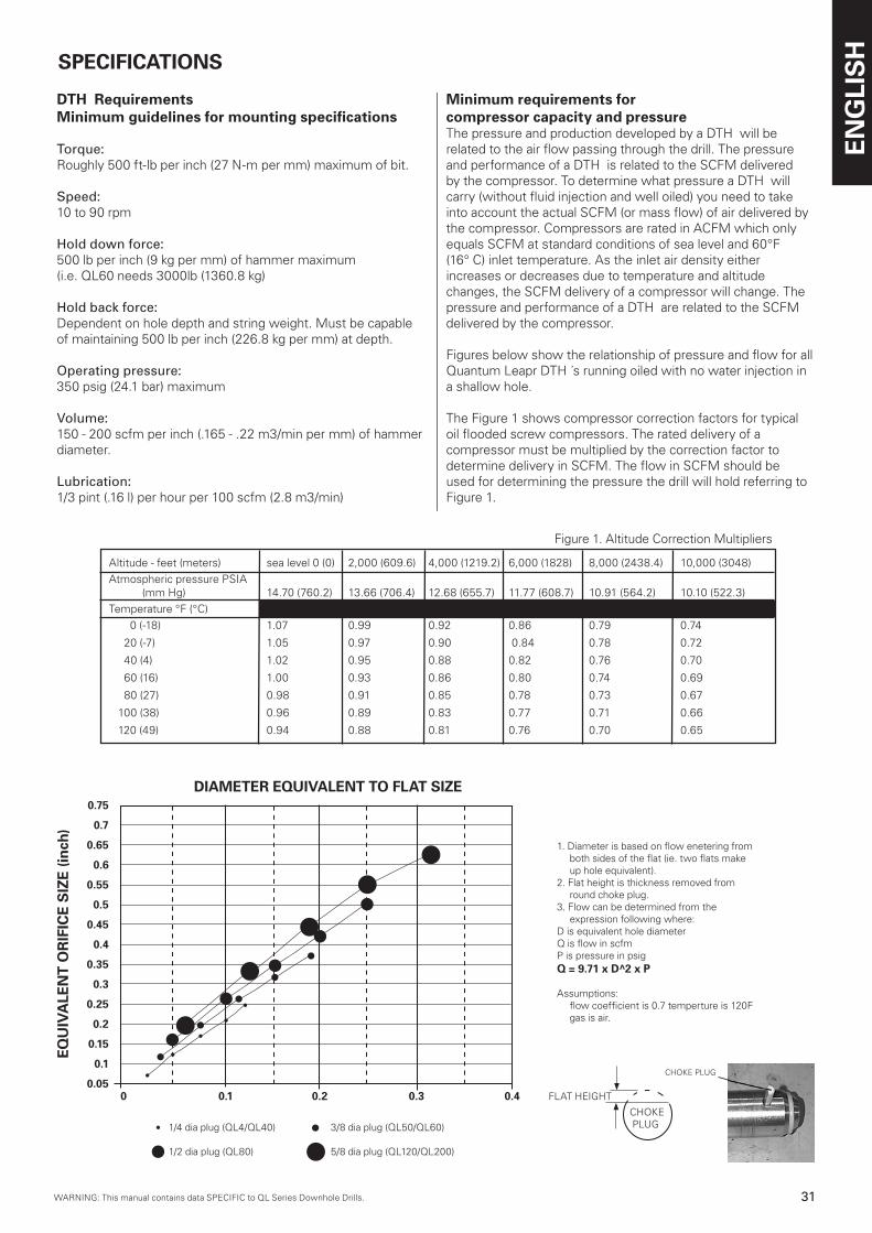
WARNING: This manual contains data SPECIFIC to QL Series Downhole Drills.WARNING: This manual contains data SPECIFIC to QL Series Downhole Drills.
ENG
LIS
H
�1WARNING: This manual contains data SPECIFIC to QL Series Downhole Drills.
Altitude - feet (meters) sea level 0 (0) 2,000 (609.6) 4,000 (1219.2) 6,000 (1828) 8,000 (2438.4) 10,000 (3048)
Atmospheric pressure PSIA (mm Hg) 14.70 (760.2) 13.66 (706.4) 12.68 (655.7) 11.77 (608.7) 10.91 (564.2) 10.10 (522.3)
Temperature °F (°C)
0 (-18) 1.07 0.99 0.92 0.86 0.79 0.74
20 (-7) 1.05 0.97 0.90 0.84 0.78 0.72
40 (4) 1.02 0.95 0.88 0.82 0.76 0.70
60 (16) 1.00 0.93 0.86 0.80 0.74 0.69
80 (27) 0.98 0.91 0.85 0.78 0.73 0.67
100 (38) 0.96 0.89 0.83 0.77 0.71 0.66
120 (49) 0.94 0.88 0.81 0.76 0.70 0.65
Figure 1. Altitude Correction Multipliers
DTH RequirementsMinimum guidelines for mounting specifications
Torque: Roughly 500 ft-lb per inch (27 N-m per mm) maximum of bit.
Speed: 10 to 90 rpm
Hold down force: 500 lb per inch (9 kg per mm) of hammer maximum(i.e. QL60 needs 3000lb (1360.8 kg)
Hold back force: Dependent on hole depth and string weight. Must be capable of maintaining 500 lb per inch (226.8 kg per mm) at depth.
Operating pressure: 350 psig (24.1 bar) maximum
Volume: 150 - 200 scfm per inch (.165 - .22 m3/min per mm) of hammer diameter.
Lubrication: 1/3 pint (.16 l) per hour per 100 scfm (2.8 m3/min)
SPECIFICATIONS
Minimum requirements for compressor capacity and pressureThe pressure and production developed by a DTH will be related to the air flow passing through the drill. The pressure and performance of a DTH is related to the SCFM delivered by the compressor. To determine what pressure a DTH will carry (without fluid injection and well oiled) you need to take into account the actual SCFM (or mass flow) of air delivered by the compressor. Compressors are rated in ACFM which only equals SCFM at standard conditions of sea level and 60°F (16° C) inlet temperature. As the inlet air density either increases or decreases due to temperature and altitude changes, the SCFM delivery of a compressor will change. The pressure and performance of a DTH are related to the SCFM delivered by the compressor.
Figures below show the relationship of pressure and flow for all Quantum Leapr DTH ´s running oiled with no water injection in a shallow hole.
The Figure 1 shows compressor correction factors for typical oil flooded screw compressors. The rated delivery of a compressor must be multiplied by the correction factor to determine delivery in SCFM. The flow in SCFM should be used for determining the pressure the drill will hold referring to Figure 1.
1. Diameter is based on flow enetering from both sides of the flat (ie. two flats make up hole equivalent).
2. Flat height is thickness removed from round choke plug.
3. Flow can be determined from the expression following where:
D is equivalent hole diameterQ is flow in scfmP is pressure in psigQ = 9.71 x D^2 x P
Assumptions: flow coefficient is 0.7 temperture is 120F
gas is air.
0.75
0.7
0.65
0.6
0.55
0.5
0.45
0.4
0.35
0.3
0.25
0.2
0.15
0.1
0.050 0.1 0.2 0.3 0.4
••
••
•
DIAMETER EQUIVALENT TO FLAT SIZE
EQU
IVA
LEN
T O
RIF
ICE
SIZ
E (in
ch)
1/4 dia plug (QL4/QL40) 3/8 dia plug (QL50/QL60)
1/2 dia plug (QL80) 5/8 dia plug (QL120/QL200)
•
FLAT HEIGHT
CHOKE PLUG
CHOKE PLUG
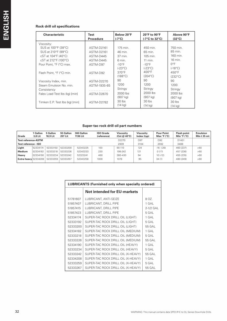
ENG
LIS
H
�2 WARNING: This manual contains data SPECIFIC to QL Series Downhole Drills.WARNING: This manual contains data SPECIFIC to QL Series Downhole Drills.
450 min.65 min.105 min.11 min.-10°F(-23°C)400°F(204°C)901200Stringy2000 lbs(907 kg)30 lbs(14 kg)
Rock drill oil specifications
Viscosity: SUS at 100°F (38°C) SUS at 210°F (99°C) cST at 104°F (40°C) cST at 212°F (100°C)Pour Point, °F (°C) max.
Flash Point, °F (°C) min.
Viscosity Index, min.Steam Emulsion No. min.ConsistencyFalex Load Test lbs (kg) [min]
Timken E.P. Test lbs (kg) [min]
ASTM-D2161ASTM-D2161ASTM-D445ASTM-D445ASTM-D97
ASTM-D92
ASTM-D2270ASTM-1935-65. . . . . . . . . . . . .ASTM-D2670
ASTM-D2782
750 min.85 min.160 min.16 min.0°F(-18°C)450°F(232°C)901200Stringy2000 lbs(907 kg)30 lbs(14 kg)
Characteristic Test Below 20°F 20°F to 90°F Above 90°F Procedure (-7°C) (-7°C to 32°C) (32°C)
175 min.46 min.37 min.6 min.-10°F(-23°C)370°F(188°C)901200Stringy
2000 lbs(907 kg)30 lbs(14 kg)
LUBRICANTS (Furnished only when specially ordered)
51781607 LUBRICANT, ANTI-SEIZE 8 OZ.
51857407 LUBRICANT, DRILL PIPE 1 GAL
51857415 LUBRICANT, DRILL PIPE 2-1/2 GAL
51857423 LUBRICANT, DRILL PIPE 5 GAL
52334174 SUPER-TAC ROCK DRILL OIL (LIGHT) 1 GAL
52333192 SUPER-TAC ROCK DRILL OIL (LIGHT) 5 GAL
52333200 SUPER-TAC ROCK DRILL OIL (LIGHT) 55 GAL
52334182 SUPER-TAC ROCK DRILL OIL (MEDIUM) 1 GAL
52333218 SUPER-TAC ROCK DRILL OIL (MEDIUM) 5 GAL
52333226 SUPER-TAC ROCK DRILL OIL (MEDIUM) 55 GAL
52334190 SUPER-TAC ROCK DRILL OIL (HEAVY) 1 GAL
52333234 SUPER-TAC ROCK DRILL OIL (HEAVY) 5 GAL
52333242 SUPER-TAC ROCK DRILL OIL (X-HEAVY) 55 GAL
52334208 SUPER-TAC ROCK DRILL OIL (X-HEAVY) 1 GAL
52333259 SUPER-TAC ROCK DRILL OIL (X-HEAVY) 5 GAL
52333267 SUPER-TAC ROCK DRILL OIL (X-HEAVY) 55 GAL
Not intended for EU-markets
Super-tac rock drill oil part numbers
1 Gallon 5 Gallon 55 Gallon 300 Gallon ISO Grade Viscosity Viscosity Pour Point Flash point EmulsionGrade 3,8 Lit 18,9 Lit 207 Lit 1136 Lit (reference) (Cst @ 40°C) Index (typ) Max °F (°C) Min °F (°C) Min t 35 ml.
Test reference-ASTM D2270 D97 D92 D1401
Test reference - ISO 2909 3104 2592 3488
Light 52334174 52333192 52333200 52343225 100 90-110 124 -16 (-26) 460 (237) >60
Medium 52334182 52333218 52333226 52343233 220 198-242 121 0 (17) 457 (236) >60
Heavy 52334190 52333234 52333242 52323241 460 380-430 94 10 (-12) 455 (235) >60
Extra heavy 52334208 52333259 52333267 52343258 1000 1078 95 34 (1) 480 (249) >60
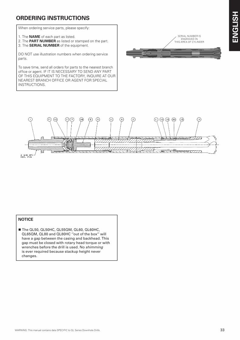
WARNING: This manual contains data SPECIFIC to QL Series Downhole Drills.WARNING: This manual contains data SPECIFIC to QL Series Downhole Drills.
ENG
LIS
H
��WARNING: This manual contains data SPECIFIC to QL Series Downhole Drills.
1 Gallon 5 Gallon 55 Gallon 300 Gallon ISO Grade Viscosity Viscosity Pour Point Flash point EmulsionGrade 3,8 Lit 18,9 Lit 207 Lit 1136 Lit (reference) (Cst @ 40°C) Index (typ) Max °F (°C) Min °F (°C) Min t 35 ml.
Test reference-ASTM D2270 D97 D92 D1401
Test reference - ISO 2909 3104 2592 3488
Light 52334174 52333192 52333200 52343225 100 90-110 124 -16 (-26) 460 (237) >60
Medium 52334182 52333218 52333226 52343233 220 198-242 121 0 (17) 457 (236) >60
Heavy 52334190 52333234 52333242 52323241 460 380-430 94 10 (-12) 455 (235) >60
Extra heavy 52334208 52333259 52333267 52343258 1000 1078 95 34 (1) 480 (249) >60
ORDERING INSTRUCTIONS
When ordering service parts, please specify:
1. The NAME of each part as listed.2. The PART NUMBER as listed or stamped on the part.3. The SERIAL NUMBER of the equipment.
DO NOT use illustration numbers when ordering service parts.
To save time, send all orders for parts to the nearest branch office or agent. IF IT IS NECESSARY TO SEND ANY PARTOF THIS EQUIPMENT TO THE FACTORY, INQUIRE AT OUR NEAREST BRANCH OFFICE OR AGENT FOR SPECIAL INSTRUCTIONS.
NOTICE
n The QL50, QL50HC, QL55QM, QL60, QL60HC, QL65QM, QL80 and QL80HC ‘’out of the box’’ will have a gap between the casing and backhead. This gap must be closed with rotary head torque or with wrenches before the drill is used. No shimming is ever required because stackup height never changes.
SERIAL NUMBER ISENGRAVED IN
THIS AREA OF CYLINDER
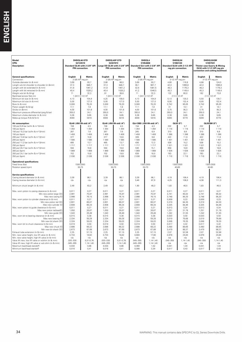
ENG
LIS
H
�4 WARNING: This manual contains data SPECIFIC to QL Series Downhole Drills.WARNING: This manual contains data SPECIFIC to QL Series Downhole Drills.
Model: DHDQL40-STD DHDQL45P-STD DHDQL4 DHDQL50 DHDQL55QMCPN: 52133519 52307873 51954808 51983120 51997591Description: Standard QL40 with 2-3/8" API
PIN connection.Large OD QL40 with 2-3/8" API
PIN connection.Standard QL4 with 2-3/8" API
PIN connection.Standard QL50 with 3-1/2 API
reg pin connection.Thicker case Quarry & Mining QL50 with 3-1/2 API reg pin
connection and cutting backhead.
General specifications: English Metric English Metric English Metric English Metric English MetricConnection: 2-3/8 API reg pin 2-3/8 API reg pin 2-3/8 API reg pin 3-1/2 API reg pin 3-1/2 API reg pinOutside diameter (in & mm) 3,69 93,7 3,86 98,0 3,69 93,7 4,60 116,8 4,88 124,0Length w/o bit shoulder to shoulder (in &mm) 37,3 946,7 37,3 946,7 38,1 967,7 42,0 1066,8 42,0 1066,8Length with bit extended (in & mm) 41,8 1061,2 41,8 1061,2 42,6 1081,5 46,3 1176,3 46,3 1176,3Length with bit retracted (in & mm) 40,4 1026,2 40,4 1026,2 41,2 1046,5 45,3 1149,4 45,3 1149,4Weight w/o bit (lb & kg) 71 32,3 81 36,8 71 32,3 132 60,0 162 73,6Backhead across flats (in) 1-3/4 X 2-1/2 AF 1-3/4 X 2-1/2 AF 1-3/4 X 2-1/2 AF 2 X 3-1/2 AF 2 X 3-1/2 AFMinimum bit size (in & mm) 4,13 104,9 4,25 108,0 4,13 104,9 5,13 130,3 5,50 139,7Maximum bit size (in & mm) 5,00 127,0 5,00 127,0 5,00 127,0 6,00 152,4 6,00 152,4Bore (in & mm) 3,000 76,20 3,000 76,20 3,000 76,20 3,742 95,05 3,742 95,05Piston weight (lb & kg) 17,1 7,8 17,1 7,8 17,1 7,8 31 14,1 31 14,1Stroke (in &mm) 4,00 101,6 4,00 101,6 4,00 101,6 3,75 95,3 3,75 95,3Maximum pressure differential (psig & bar) 350,0 24,1 350,0 24,1 350,0 24,1 350,0 24,1 350,0 24,1Maximum choke diameter (in & mm) 0,38 9,65 0,38 9,65 0,38 9,65 0,38 9,65 0,38 9,65Make-up torque (ft-lb & N-m) 4000 5416 4000 5416 4000 5416 5000 6770 5000 6770
Air consumption: QL40 (.050 lift-std) (4") QL40 (.050 lift-std) (4") QL4 OBS (.050 lift-std) (4") QL50 (5") QL55QM (5")100 psi/ 6,9 bar (scfm & m^3/min) 158 4,5 158 4,5 154 4,3 202 5,7 202 5,7100 psi (bpm) 1 354 1 354 1 354 1 354 1 354 1 354 1 116 1 116 1 116 1 116150 psi/ 10,3 bar (scfm & m^3/min) 267 7,6 267 7,6 245 6,9 310 8,8 310 8,8150 psi (bpm) 1 459 1 459 1 459 1 459 1 459 1 459 1 266 1 266 1 266 1 266200 psi/ 13,8 bar (scfm & m^3/min) 377 10,6 377 10,6 339 9,6 422 11,9 422 11,9200 psi (bpm) 1 580 1 580 1 580 1 580 1 580 1 580 1 401 1 401 1 401 1 401250 psi/ 17,2 bar (scfm & m^3/min) 485 13,7 485 13,7 436 12,3 538 15,2 538 15,2250 psi (bpm) 1 717 1 717 1 717 1 717 1 717 1 717 1 521 1 521 1 521 1 521300 psi/ 20,7 bar (scfm & m^3/min) 594 16,8 594 16,8 536 15,1 658 18,6 658 18,6300 psi (bpm) 1 869 1 869 1 869 1 869 1 869 1 869 1 626 1 626 1 626 1 626350 psi/ 24,1 bar (scfm & m^3/min) 702 19,8 702 19,8 638 18,0 783 22,1 783 22,1350 psi (bpm) 2 036 2 036 2 036 2 036 2 036 2 036 1 716 1 716 1 716 1 716
Operational specifications:Feed force (lbs) 1500-2000 1500-2000 1500-2000 1500-2500 1500-2500Rotation speed (rpm) 50-70 50-70 50-70 40-60 40-60
Service specifications:Casing discard diameter (in & mm) 3,39 86,1 3,39 86,1 3,39 86,1 4,19 106,4 4,19 106,4Casing reverse diameter (in & mm) n/a n/a n/a n/a 3,46 87,9 4,25 108,0 4,38 111,3
Minimum chuck length (in & mm) 2,49 63,2 2,49 63,2 1,90 48,3 1,83 46,5 1,83 46,5
Max. worn piston to casing clearance (in & mm) 0,011 0,27 0,011 0,27 0,011 0,27 0,011 0,27 0,011 0,27Min new piston large OD: 2,991 75,97 2,991 75,97 2,991 75,97 3,741 95,02 3,741 95,02
Max new casing ID: 2,998 76,15 2,998 76,15 2,998 76,15 3,748 95,20 3,748 95,20Max. worn piston to cylinder clearance (in & mm) 0,011 0,27 0,011 0,27 0,011 0,27 0,009 0,23 0,009 0,23
Min new piston tail OD: 2,601 66,07 2,601 66,07 2,601 66,07 3,319 84,30 3,319 84,30Max new cylinder ID: 2,608 66,24 2,608 66,24 2,608 66,24 3,325 84,46 3,325 84,46
Max. worn piston to guide clearance (in & mm) 0,011 0,27 0,011 0,27 0,011 0,27 0,013 0,34 0,013 0,34Max new piston tail/sealID: 1,050 26,67 1,050 26,67 1,050 26,67 1,251 31,78 1,251 31,78
Min new guide OD: 1,043 26,49 1,043 26,49 1,043 26,49 1,242 31,55 1,242 31,55Max. worn bit to bearing clearance (in & mm) 0,015 0,38 0,015 0,38 0,015 0,38 0,020 0,50 0,020 0,50
Max new bearing ID: 2,334 59,28 2,334 59,28 2,334 59,28 3,019 76,68 3,019 76,68Min new bit shank OD: 2,324 59,03 2,324 59,03 2,324 59,03 3,006 76,35 3,006 76,35
Max. worn bit to chuck clearance (in & mm) 0,019 0,50 0,019 0,50 0,019 0,50 0,017 0,42 0,017 0,42Max new chuck ID: 2,686 68,22 2,686 68,22 2,686 68,22 3,490 88,65 3,490 88,65
Min new bit shank OD: 2,673 67,89 2,673 67,89 2,673 67,89 3,479 88,37 3,479 88,37Exhaust tube extension (in & mm): 2,25 57,15 2,25 57,15 2,25 57,15 2,07 52,58 2,07 52,58Min. new valve height, low lift valve (in & mm): 0,733 18,62 0,733 18,62 0,693 17,60 0,978 24,84 0,978 24,84Min. new valve height, high lift valve (in & mm): n/a n/a n/a n/a n/a n/a n/a n/a n/a n/aValve lift new, low lift valve or w/shim (in & mm): .020-.030 0,51-0,76 .020-.030 0,51-0,76 .045-.055 1,14-1,40 .045-.055 1,14-1,40 .045-.055 1,14-1,40Valve lift new, high lift valve or w/o shim (in & mm): .045-.055 1,14-1,40 .045-.055 1,14-1,40 .045-.055 1,14-1,40 n/a n/a n/a n/aMaximum backhead standoff: 0,034 0,86 0,034 0,86 0,060 1,52 0,041 1,04 0,041 1,04Minimum backhead standoff: 0,016 0,41 0,016 0,41 0,090 2,29 0,017 0,43 0,017 0,43
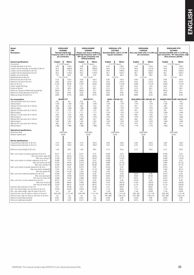
WARNING: This manual contains data SPECIFIC to QL Series Downhole Drills.WARNING: This manual contains data SPECIFIC to QL Series Downhole Drills.
ENG
LIS
H
�5WARNING: This manual contains data SPECIFIC to QL Series Downhole Drills.
Model: DHDQL50HF DHDQL55QMHF DHDQL60+ STD DHDQL60NL DHDQL60HF-STDCPN: 52284882 52284890 52314820 51903326 52310604Description: Standard QL50 high
frequency with 3-1/2 API reg pin connection.
Thicker case Quarry & Mining QL50 high frequency with 3-1/2
API reg pin connection and cutting backhead.
Standard QL60+ with 3-1/2 API reg pin connection.
Non-Lube QL60 with 3-1/2 API reg pin connection.
Standard QL60HF with 3-1/2 API reg pin connection. "W" style piston, high
blow pressure cylinder.
General specifications: English Metric English Metric English Metric English Metric English MetricConnection: 3-1/2 API reg pin 3-1/2 API reg pin 3-1/2 API reg pin 3-1/2 API reg pin 3-1/2 API reg pinOutside diameter (in & mm) 4,60 116,8 4,88 124,0 5,44 138,2 5,44 138,2 5,44 138,2Length w/o bit shoulder to shoulder (in &mm) 42,0 1066,8 42,0 1066,8 44,6 1131,8 44,6 1131,8 44,6 1131,8Length with bit extended (in & mm) 46,3 1176,3 46,3 1176,3 49,5 1256,3 49,5 1256,3 49,5 1256,3Length with bit retracted (in & mm) 45,3 1149,4 45,3 1149,4 48,1 1220,7 48,1 1220,7 48,1 1220,7Weight w/o bit (lb & kg) 132 60,0 162 73,6 200 90,9 200 90,9 200 90,9Backhead across flats (in) 2 X 3-1/2 AF 2 X 3-1/2 AF 2 X 4 AF 2 X 4 AF 2 X 4 AFMinimum bit size (in & mm) 5,13 130,3 5,50 139,7 6,00 152,4 6,00 152,4 6,00 152,4Maximum bit size (in & mm) 6,00 152,4 6,00 152,4 8,50 215,9 8,50 215,9 8,50 215,9Bore (in & mm) 3,742 95,05 3,742 95,05 4,500 114,30 4,500 114,30 4,500 114,30Piston weight (lb & kg) 33 15,0 31 14,1 42,6 19,4 42,6 19,4 42,6 19,4Stroke (in &mm) 2,75 69,9 3,75 95,3 3,75 95,3 3,75 95,3 3,75 95,3Maximum pressure differential (psig & bar) 350,0 24,1 350,0 24,1 350,0 24,1 350,0 24,1 350,0 24,1Maximum choke diameter (in & mm) 0,38 9,65 0,38 9,65 0,38 9,65 0,38 9,65 0,38 9,65Make-up torque (ft-lb & N-m) 5000 6770 5000 6770 6000 8124 6000 8124 6000 8124
Air consumption: QL50HF (5") QL50HF (5") QL60+ (.050 lift) (6") QL60 NON-LUBE (.050 lift) (6") QL60HF-HIGH BLOW (.050 lift) (6") QL65QM+ (.050 lift) (6")100 psi/ 6,9 bar (scfm & m^3/min) 232 6,5 232 6,5 305 8,6 305 8,6 314 8,9100 psi (bpm) 1 445 1 445 1 445 1 445 1 270 1 270 1 270 1 270 1 330 1 330150 psi/ 10,3 bar (scfm & m^3/min) 356 10,0 356 10,0 431 12,2 431 12,2 448 12,6150 psi (bpm) 1 588 1 588 1 588 1 588 1 370 1 370 1 370 1 370 1 449 1 449200 psi/ 13,8 bar (scfm & m^3/min) 475 13,4 475 13,4 561 15,8 561 15,8 581 16,4200 psi (bpm) 1 711 1 711 1 711 1 711 1 470 1 470 1 470 1 470 1 569 1 569250 psi/ 17,2 bar (scfm & m^3/min) 589 16,6 589 16,6 695 19,6 695 19,6 714 20,2250 psi (bpm) 1 816 1 816 1 816 1 816 1 570 1 570 1 570 1 570 1 689 1 689300 psi/ 20,7 bar (scfm & m^3/min) 698 19,7 698 19,7 832 23,5 832 23,5 848 24,0300 psi (bpm) 1 901 1 901 1 901 1 901 1 670 1 670 1 670 1 670 1 809 1 809350 psi/ 24,1 bar (scfm & m^3/min) 803 22,7 803 22,7 973 27,5 973 27,5 981 27,7350 psi (bpm) 1 966 1 966 1 966 1 966 1 770 1 770 1 770 1 770 1 928 1 928
Operational specifications:Feed force (lbs) 1500-2500 1500-2500 2000-3000 2000-3000 2000-3000Rotation speed (rpm) 40-60 40-60 30-50 30-50 30-50
Service specifications:Casing discard diameter (in & mm) 4,19 106,4 4,19 106,4 5,06 128,5 5,06 128,5 5,06 128,5Casing reverse diameter (in & mm) 4,25 108,0 4,25 108,0 5,25 133,4 5,25 133,4 5,25 133,4
Minimum chuck length (in & mm) 1,83 46,5 1,83 46,5 2,15 54,6 2,15 54,6 2,15 54,6
Max. worn piston to casing clearance (in & mm) 0,011 0,27 0,011 0,27 0,009 0,23 0,009 0,23 0,009 0,23Min new piston large OD: 3,741 95,02 3,741 95,02 4,492 114,10 4,492 114,10 4,492 114,10
Max new casing ID: 3,748 95,20 3,748 95,20 4,498 114,25 4,498 114,25 4,498 114,25Max. worn piston to cylinder clearance (in & mm) 0,009 0,23 0,009 0,23 0,009 0,23 0,009 0,23 0,009 0,23
Min new piston tail OD: 3,319 84,30 3,319 84,30 3,985 101,22 3,985 101,22 3,985 101,22Max new cylinder ID: 3,325 84,46 3,325 84,46 3,991 101,37 3,991 101,37 3,991 101,37
Max. worn piston to guide clearance (in & mm) 0,013 0,34 0,013 0,34 0,016 0,42 0,016 0,42 0,016 0,42Max new piston tail/sealID: 1,251 31,78 1,251 31,78 1,502 38,15 1,502 38,15 1,502 38,15
Min new guide OD: 1,242 31,55 1,242 31,55 1,491 37,87 1,491 37,87 1,491 37,87Max. worn bit to bearing clearance (in & mm) 0,020 0,50 0,020 0,50 0,015 0,38 0,015 0,38 0,015 0,38
Max new bearing ID: 3,019 76,68 3,019 76,68 3,623 92,02 3,623 92,02 3,623 92,02Min new bit shank OD: 3,006 76,35 3,006 76,35 3,613 91,77 3,613 91,77 3,613 91,77
Max. worn bit to chuck clearance (in & mm) 0,017 0,42 0,017 0,42 0,018 0,46 0,018 0,46 0,018 0,46Max new chuck ID: 3,490 88,65 3,490 88,65 4,187 106,35 4,187 106,35 4,187 106,35
Min new bit shank OD: 3,479 88,37 3,479 88,37 4,175 106,05 4,175 106,05 4,175 106,05Exhaust tube extension (in & mm): 2,07 52,58 2,07 52,58 2,31 58,67 2,31 58,67 2,31 58,67Min. new valve height, low lift valve (in & mm): 0,978 24,84 0,978 24,84 1,174 29,82 1,174 29,82 1,174 29,82Min. new valve height, high lift valve (in & mm): n/a n/a n/a n/a 1,144 29,06 1,144 29,06 1,144 29,06Valve lift new, low lift valve or w/shim (in & mm): .045-.055 1,14-1,40 .045-.055 1,14-1,40 .045-.055 1,14-1,40 .045-.055 1,14-1,40 .045-.055 1,14-1,40Valve lift new, high lift valve or w/o shim (in & mm): n/a n/a n/a n/a .075-.085 1,90-2,16 .075-.085 1,90-2,16 .075-.085 1,90-2,16Maximum backhead standoff: 0,041 1,04 0,041 1,04 0,034 0,86 0,034 0,86 0,034 0,86Minimum backhead standoff: 0,017 0,43 0,017 0,43 0,013 0,33 0,013 0,33 0,013 0,33
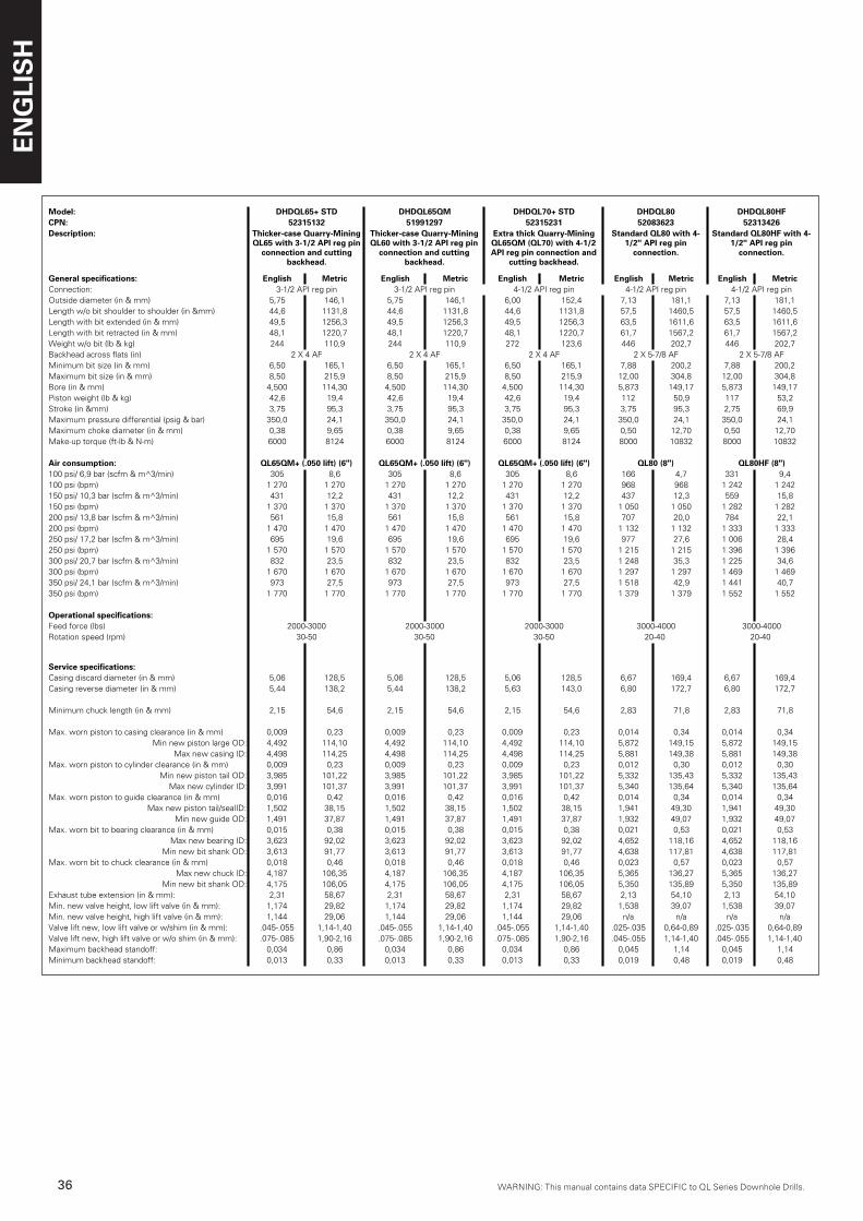
ENG
LIS
H
�6 WARNING: This manual contains data SPECIFIC to QL Series Downhole Drills.WARNING: This manual contains data SPECIFIC to QL Series Downhole Drills.
Model: DHDQL65+ STD DHDQL65QM DHDQL70+ STD DHDQL80 DHDQL80HFCPN: 52315132 51991297 52315231 52083623 52313426Description: Thicker-case Quarry-Mining
QL65 with 3-1/2 API reg pin connection and cutting
backhead.
Thicker-case Quarry-Mining QL60 with 3-1/2 API reg pin
connection and cutting backhead.
Extra thick Quarry-Mining QL65QM (QL70) with 4-1/2 API reg pin connection and
cutting backhead.
Standard QL80 with 4-1/2" API reg pin
connection.
Standard QL80HF with 4-1/2" API reg pin
connection.
General specifications: English Metric English Metric English Metric English Metric English MetricConnection: 3-1/2 API reg pin 3-1/2 API reg pin 4-1/2 API reg pin 4-1/2 API reg pin 4-1/2 API reg pinOutside diameter (in & mm) 5,75 146,1 5,75 146,1 6,00 152,4 7,13 181,1 7,13 181,1Length w/o bit shoulder to shoulder (in &mm) 44,6 1131,8 44,6 1131,8 44,6 1131,8 57,5 1460,5 57,5 1460,5Length with bit extended (in & mm) 49,5 1256,3 49,5 1256,3 49,5 1256,3 63,5 1611,6 63,5 1611,6Length with bit retracted (in & mm) 48,1 1220,7 48,1 1220,7 48,1 1220,7 61,7 1567,2 61,7 1567,2Weight w/o bit (lb & kg) 244 110,9 244 110,9 272 123,6 446 202,7 446 202,7Backhead across flats (in) 2 X 4 AF 2 X 4 AF 2 X 4 AF 2 X 5-7/8 AF 2 X 5-7/8 AFMinimum bit size (in & mm) 6,50 165,1 6,50 165,1 6,50 165,1 7,88 200,2 7,88 200,2Maximum bit size (in & mm) 8,50 215,9 8,50 215,9 8,50 215,9 12,00 304,8 12,00 304,8Bore (in & mm) 4,500 114,30 4,500 114,30 4,500 114,30 5,873 149,17 5,873 149,17Piston weight (lb & kg) 42,6 19,4 42,6 19,4 42,6 19,4 112 50,9 117 53,2Stroke (in &mm) 3,75 95,3 3,75 95,3 3,75 95,3 3,75 95,3 2,75 69,9Maximum pressure differential (psig & bar) 350,0 24,1 350,0 24,1 350,0 24,1 350,0 24,1 350,0 24,1Maximum choke diameter (in & mm) 0,38 9,65 0,38 9,65 0,38 9,65 0,50 12,70 0,50 12,70Make-up torque (ft-lb & N-m) 6000 8124 6000 8124 6000 8124 8000 10832 8000 10832
Air consumption: QL65QM+ (.050 lift) (6") QL65QM+ (.050 lift) (6") QL65QM+ (.050 lift) (6") QL80 (8") QL80HF (8")100 psi/ 6,9 bar (scfm & m^3/min) 305 8,6 305 8,6 305 8,6 166 4,7 331 9,4100 psi (bpm) 1 270 1 270 1 270 1 270 1 270 1 270 968 968 1 242 1 242150 psi/ 10,3 bar (scfm & m^3/min) 431 12,2 431 12,2 431 12,2 437 12,3 559 15,8150 psi (bpm) 1 370 1 370 1 370 1 370 1 370 1 370 1 050 1 050 1 282 1 282200 psi/ 13,8 bar (scfm & m^3/min) 561 15,8 561 15,8 561 15,8 707 20,0 784 22,1200 psi (bpm) 1 470 1 470 1 470 1 470 1 470 1 470 1 132 1 132 1 333 1 333250 psi/ 17,2 bar (scfm & m^3/min) 695 19,6 695 19,6 695 19,6 977 27,6 1 006 28,4250 psi (bpm) 1 570 1 570 1 570 1 570 1 570 1 570 1 215 1 215 1 396 1 396300 psi/ 20,7 bar (scfm & m^3/min) 832 23,5 832 23,5 832 23,5 1 248 35,3 1 225 34,6300 psi (bpm) 1 670 1 670 1 670 1 670 1 670 1 670 1 297 1 297 1 469 1 469350 psi/ 24,1 bar (scfm & m^3/min) 973 27,5 973 27,5 973 27,5 1 518 42,9 1 441 40,7350 psi (bpm) 1 770 1 770 1 770 1 770 1 770 1 770 1 379 1 379 1 552 1 552
Operational specifications:Feed force (lbs) 2000-3000 2000-3000 2000-3000 3000-4000 3000-4000Rotation speed (rpm) 30-50 30-50 30-50 20-40 20-40
Service specifications:Casing discard diameter (in & mm) 5,06 128,5 5,06 128,5 5,06 128,5 6,67 169,4 6,67 169,4Casing reverse diameter (in & mm) 5,44 138,2 5,44 138,2 5,63 143,0 6,80 172,7 6,80 172,7
Minimum chuck length (in & mm) 2,15 54,6 2,15 54,6 2,15 54,6 2,83 71,8 2,83 71,8
Max. worn piston to casing clearance (in & mm) 0,009 0,23 0,009 0,23 0,009 0,23 0,014 0,34 0,014 0,34Min new piston large OD: 4,492 114,10 4,492 114,10 4,492 114,10 5,872 149,15 5,872 149,15
Max new casing ID: 4,498 114,25 4,498 114,25 4,498 114,25 5,881 149,38 5,881 149,38Max. worn piston to cylinder clearance (in & mm) 0,009 0,23 0,009 0,23 0,009 0,23 0,012 0,30 0,012 0,30
Min new piston tail OD: 3,985 101,22 3,985 101,22 3,985 101,22 5,332 135,43 5,332 135,43Max new cylinder ID: 3,991 101,37 3,991 101,37 3,991 101,37 5,340 135,64 5,340 135,64
Max. worn piston to guide clearance (in & mm) 0,016 0,42 0,016 0,42 0,016 0,42 0,014 0,34 0,014 0,34Max new piston tail/sealID: 1,502 38,15 1,502 38,15 1,502 38,15 1,941 49,30 1,941 49,30
Min new guide OD: 1,491 37,87 1,491 37,87 1,491 37,87 1,932 49,07 1,932 49,07Max. worn bit to bearing clearance (in & mm) 0,015 0,38 0,015 0,38 0,015 0,38 0,021 0,53 0,021 0,53
Max new bearing ID: 3,623 92,02 3,623 92,02 3,623 92,02 4,652 118,16 4,652 118,16Min new bit shank OD: 3,613 91,77 3,613 91,77 3,613 91,77 4,638 117,81 4,638 117,81
Max. worn bit to chuck clearance (in & mm) 0,018 0,46 0,018 0,46 0,018 0,46 0,023 0,57 0,023 0,57Max new chuck ID: 4,187 106,35 4,187 106,35 4,187 106,35 5,365 136,27 5,365 136,27
Min new bit shank OD: 4,175 106,05 4,175 106,05 4,175 106,05 5,350 135,89 5,350 135,89Exhaust tube extension (in & mm): 2,31 58,67 2,31 58,67 2,31 58,67 2,13 54,10 2,13 54,10Min. new valve height, low lift valve (in & mm): 1,174 29,82 1,174 29,82 1,174 29,82 1,538 39,07 1,538 39,07Min. new valve height, high lift valve (in & mm): 1,144 29,06 1,144 29,06 1,144 29,06 n/a n/a n/a n/aValve lift new, low lift valve or w/shim (in & mm): .045-.055 1,14-1,40 .045-.055 1,14-1,40 .045-.055 1,14-1,40 .025-.035 0,64-0,89 .025-.035 0,64-0,89Valve lift new, high lift valve or w/o shim (in & mm): .075-.085 1,90-2,16 .075-.085 1,90-2,16 .075-.085 1,90-2,16 .045-.055 1,14-1,40 .045-.055 1,14-1,40Maximum backhead standoff: 0,034 0,86 0,034 0,86 0,034 0,86 0,045 1,14 0,045 1,14Minimum backhead standoff: 0,013 0,33 0,013 0,33 0,013 0,33 0,019 0,48 0,019 0,48
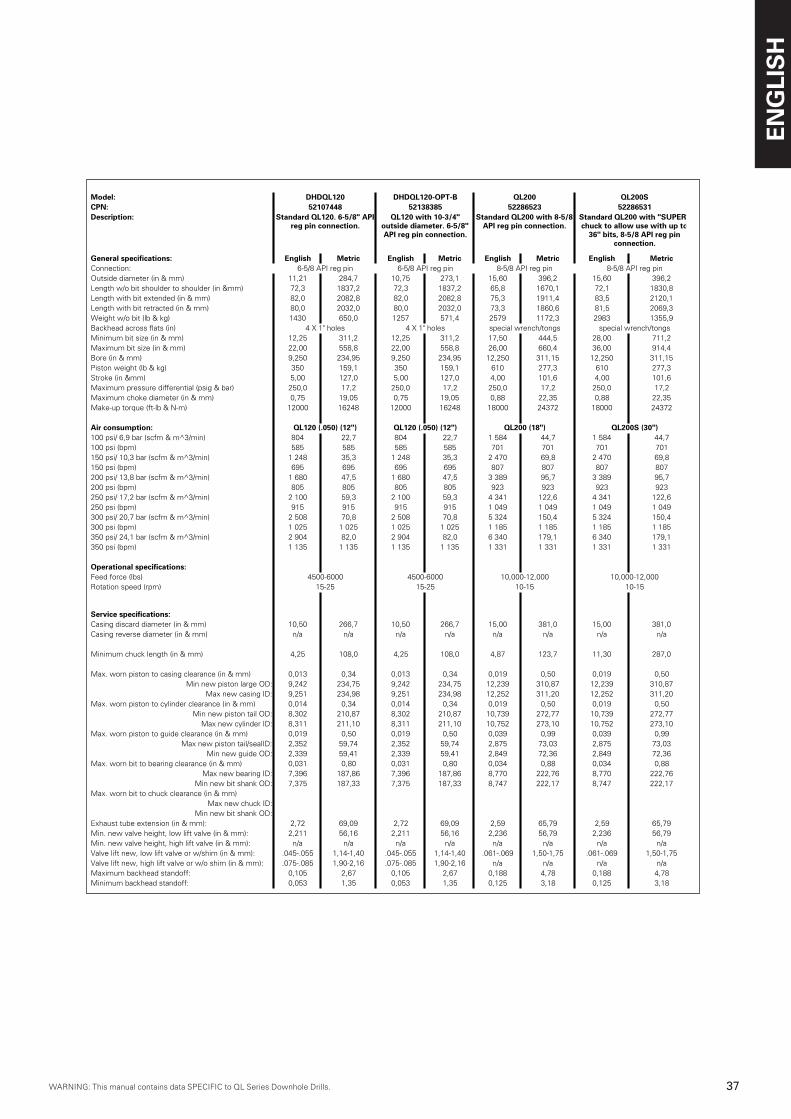
WARNING: This manual contains data SPECIFIC to QL Series Downhole Drills.WARNING: This manual contains data SPECIFIC to QL Series Downhole Drills.
ENG
LIS
H
�7WARNING: This manual contains data SPECIFIC to QL Series Downhole Drills.
Model: DHDQL120 DHDQL120-OPT-B QL200 QL200SCPN: 52107448 52138385 52286523 52286531Description: Standard QL120. 6-5/8" API
reg pin connection.QL120 with 10-3/4"
outside diameter. 6-5/8" API reg pin connection.
Standard QL200 with 8-5/8 API reg pin connection.
Standard QL200 with "SUPER" chuck to allow use with up to
36" bits, 8-5/8 API reg pin connection.
General specifications: English Metric English Metric English Metric English MetricConnection: 6-5/8 API reg pin 6-5/8 API reg pin 8-5/8 API reg pin 8-5/8 API reg pinOutside diameter (in & mm) 11,21 284,7 10,75 273,1 15,60 396,2 15,60 396,2Length w/o bit shoulder to shoulder (in &mm) 72,3 1837,2 72,3 1837,2 65,8 1670,1 72,1 1830,8Length with bit extended (in & mm) 82,0 2082,8 82,0 2082,8 75,3 1911,4 83,5 2120,1Length with bit retracted (in & mm) 80,0 2032,0 80,0 2032,0 73,3 1860,6 81,5 2069,3Weight w/o bit (lb & kg) 1430 650,0 1257 571,4 2579 1172,3 2983 1355,9Backhead across flats (in) 4 X 1" holes 4 X 1" holes special wrench/tongs special wrench/tongsMinimum bit size (in & mm) 12,25 311,2 12,25 311,2 17,50 444,5 28,00 711,2Maximum bit size (in & mm) 22,00 558,8 22,00 558,8 26,00 660,4 36,00 914,4Bore (in & mm) 9,250 234,95 9,250 234,95 12,250 311,15 12,250 311,15Piston weight (lb & kg) 350 159,1 350 159,1 610 277,3 610 277,3Stroke (in &mm) 5,00 127,0 5,00 127,0 4,00 101,6 4,00 101,6Maximum pressure differential (psig & bar) 250,0 17,2 250,0 17,2 250,0 17,2 250,0 17,2Maximum choke diameter (in & mm) 0,75 19,05 0,75 19,05 0,88 22,35 0,88 22,35Make-up torque (ft-lb & N-m) 12000 16248 12000 16248 18000 24372 18000 24372
Air consumption: QL120 (.050) (12") QL120 (.050) (12") QL200 (18") QL200S (30")100 psi/ 6,9 bar (scfm & m^3/min) 804 22,7 804 22,7 1 584 44,7 1 584 44,7100 psi (bpm) 585 585 585 585 701 701 701 701150 psi/ 10,3 bar (scfm & m^3/min) 1 248 35,3 1 248 35,3 2 470 69,8 2 470 69,8150 psi (bpm) 695 695 695 695 807 807 807 807200 psi/ 13,8 bar (scfm & m^3/min) 1 680 47,5 1 680 47,5 3 389 95,7 3 389 95,7200 psi (bpm) 805 805 805 805 923 923 923 923250 psi/ 17,2 bar (scfm & m^3/min) 2 100 59,3 2 100 59,3 4 341 122,6 4 341 122,6250 psi (bpm) 915 915 915 915 1 049 1 049 1 049 1 049300 psi/ 20,7 bar (scfm & m^3/min) 2 508 70,8 2 508 70,8 5 324 150,4 5 324 150,4300 psi (bpm) 1 025 1 025 1 025 1 025 1 185 1 185 1 185 1 185350 psi/ 24,1 bar (scfm & m^3/min) 2 904 82,0 2 904 82,0 6 340 179,1 6 340 179,1350 psi (bpm) 1 135 1 135 1 135 1 135 1 331 1 331 1 331 1 331
Operational specifications:Feed force (lbs) 4500-6000 4500-6000 10,000-12,000 10,000-12,000Rotation speed (rpm) 15-25 15-25 10-15 10-15
Service specifications:Casing discard diameter (in & mm) 10,50 266,7 10,50 266,7 15,00 381,0 15,00 381,0Casing reverse diameter (in & mm) n/a n/a n/a n/a n/a n/a n/a n/a
Minimum chuck length (in & mm) 4,25 108,0 4,25 108,0 4,87 123,7 11,30 287,0
Max. worn piston to casing clearance (in & mm) 0,013 0,34 0,013 0,34 0,019 0,50 0,019 0,50Min new piston large OD: 9,242 234,75 9,242 234,75 12,239 310,87 12,239 310,87
Max new casing ID: 9,251 234,98 9,251 234,98 12,252 311,20 12,252 311,20Max. worn piston to cylinder clearance (in & mm) 0,014 0,34 0,014 0,34 0,019 0,50 0,019 0,50
Min new piston tail OD: 8,302 210,87 8,302 210,87 10,739 272,77 10,739 272,77Max new cylinder ID: 8,311 211,10 8,311 211,10 10,752 273,10 10,752 273,10
Max. worn piston to guide clearance (in & mm) 0,019 0,50 0,019 0,50 0,039 0,99 0,039 0,99Max new piston tail/sealID: 2,352 59,74 2,352 59,74 2,875 73,03 2,875 73,03
Min new guide OD: 2,339 59,41 2,339 59,41 2,849 72,36 2,849 72,36Max. worn bit to bearing clearance (in & mm) 0,031 0,80 0,031 0,80 0,034 0,88 0,034 0,88
Max new bearing ID: 7,396 187,86 7,396 187,86 8,770 222,76 8,770 222,76Min new bit shank OD: 7,375 187,33 7,375 187,33 8,747 222,17 8,747 222,17
Max. worn bit to chuck clearance (in & mm)Max new chuck ID:
Min new bit shank OD:Exhaust tube extension (in & mm): 2,72 69,09 2,72 69,09 2,59 65,79 2,59 65,79Min. new valve height, low lift valve (in & mm): 2,211 56,16 2,211 56,16 2,236 56,79 2,236 56,79Min. new valve height, high lift valve (in & mm): n/a n/a n/a n/a n/a n/a n/a n/aValve lift new, low lift valve or w/shim (in & mm): .045-.055 1,14-1,40 .045-.055 1,14-1,40 .061-.069 1,50-1,75 .061-.069 1,50-1,75Valve lift new, high lift valve or w/o shim (in & mm): .075-.085 1,90-2,16 .075-.085 1,90-2,16 n/a n/a n/a n/aMaximum backhead standoff: 0,105 2,67 0,105 2,67 0,188 4,78 0,188 4,78Minimum backhead standoff: 0,053 1,35 0,053 1,35 0,125 3,18 0,125 3,18
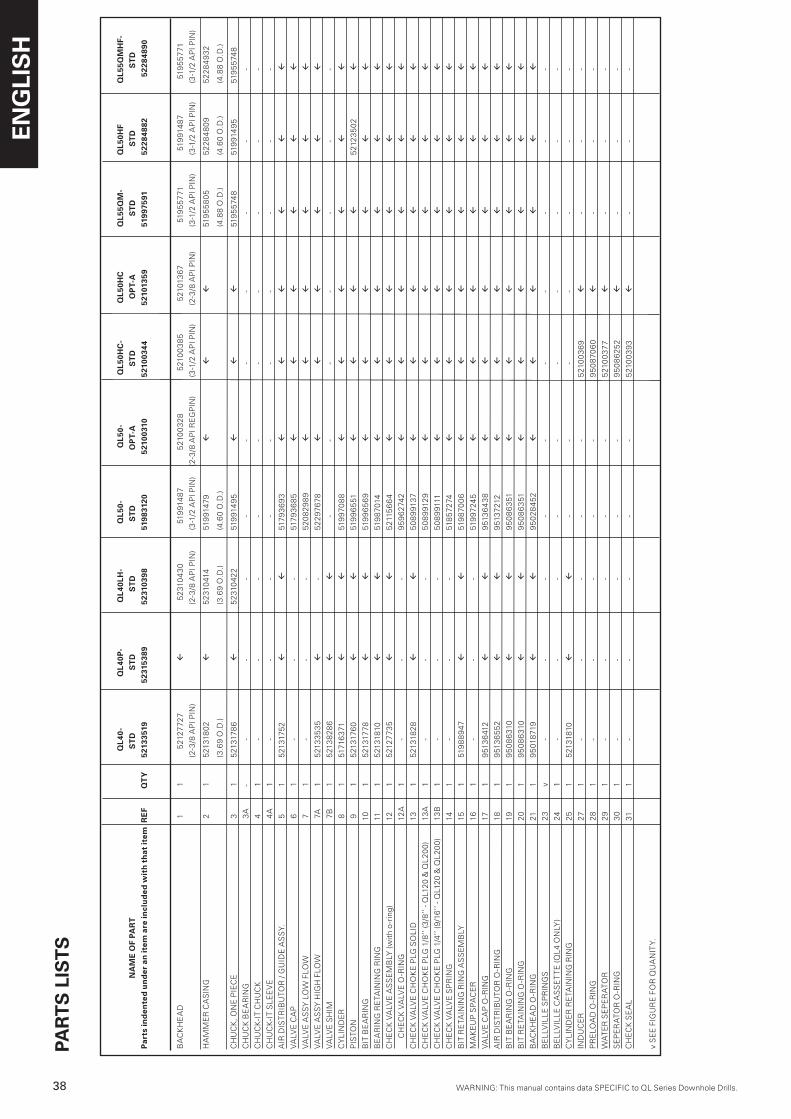
ENG
LIS
H
�8 WARNING: This manual contains data SPECIFIC to QL Series Downhole Drills.WARNING: This manual contains data SPECIFIC to QL Series Downhole Drills.
PAR
TS L
ISTS
QL4
0-
Q
L40P
- Q
L40L
H-
Q
L50-
QL5
0-
QL5
0HC
- Q
L50H
C
QL5
5QM
- Q
L50H
F Q
L55Q
MH
F-
NA
ME
OF
PAR
T
ST
D
ST
D
ST
D
S
TD
O
PT-
A
S
TD
OP
T-A
ST
D
S
TD
S
TD
Par
ts in
den
ted
un
der
an
item
are
incl
ud
ed w
ith
that
item
RE
F Q
TY
52
1335
19
5231
5389
52
3103
98
5198
3120
52
1003
10
5210
0344
52
1013
59
5199
7591
52
2848
82
52
2848
90
BA
CK
HE
AD
1
1
521
2772
7 fl
5
231
04
30
51
991
48
7 5
210
03
28
5
210
03
85
521
013
67
519
55
771
5
1991
48
7 5
195
57
71
(2
-3/8
AP
I PIN
)
(2-3
/8 A
PI P
IN)
(3-1
/2 A
PI P
IN)
(2
-3/8
AP
I RE
GP
IN)
(3-1
/2 A
PI P
IN)
(2-3
/8 A
PI P
IN)
(3-1
/2 A
PI P
IN)
(3-1
/2 A
PI P
IN)
(3-1
/2 A
PI P
IN)
HA
MM
ER
CA
SIN
G
2
1
521
318
02
fl
52
310
414
519
9147
9
fl
fl
fl
51
95
58
05
52
28
48
09
52
28
49
32
(3
.69
O.D
.)
(3.6
9 O
.D.)
(4.6
0 O
.D.)
(4
.88
O.D
.) (4
.60
O.D
.) (4
.88
O.D
.)
CH
UC
K, O
NE
PIE
CE
3
1
5
2131
78
6
fl
52
310
422
51
991
49
5
fl
fl
fl
51
95
574
8
519
914
95
51
95
574
8
CH
UC
K B
EA
RIN
G
3A
-
-
-
-
-
-
-
-
-
-
-
CH
UC
K-I
T C
HU
CK
4
1
-
-
-
-
-
-
-
-
-
-
CH
UC
K-I
T S
LE
EV
E
4A
1
-
-
-
-
-
-
-
-
-
-
AIR
DIS
TR
IBU
TOR
/ G
UID
E A
SS
Y.
5
1
521
3175
2
fl
fl
51
793
69
3
fl
fl
fl
fl
fl
fl
VA
LVE
CA
P
6
1
-
-
- 51
793
68
5
fl
fl
fl
fl
fl
fl
VA
LVE
AS
SY
LO
W F
LOW
7
1
-
-
-
5
20
82
98
9
fl
fl
fl
fl
fl
fl
VA
LVE
AS
SY
HIG
H F
LOW
7
A
1
521
33
53
5 fl
-
52
297
67
8
fl
fl
fl
fl
fl
fl
VA
LVE
SH
IM
7B
1
5
213
82
86
fl
fl
-
-
-
-
-
-
-
CY
LIN
DE
R
8
1
5171
637
1 fl
fl
519
970
88
fl
fl
fl
fl
fl
fl
PIS
TON
9
1
5
2131
760
fl
fl
51
99
65
51
fl
fl
fl
fl
521
23
50
2
fl
BIT
BE
AR
ING
1
0
1
521
317
78
fl
fl
51
99
65
69
fl
fl
fl
fl
fl
fl
BE
AR
ING
RE
TAIN
ING
RIN
G
11
1
5
2131
810
fl
fl
519
870
14
fl
fl
fl
fl
fl
fl
CH
EC
K V
ALV
E A
SS
EM
BLY
(with
o-r
ing)
1
2 1
5
2127
73
5 fl
fl
521
156
64
fl
fl
fl
fl
fl
fl
C
HE
CK
VA
LVE
O-R
ING
1
2A
1
-
-
-
9
59
627
42
fl
fl
fl
fl
fl
fl
CH
EC
K V
ALV
E C
HO
KE
PLG
SO
LID
1
3
1
521
318
28
fl
fl
5
08
991
37
fl
fl
fl
fl
fl
fl
CH
EC
K V
ALV
E C
HO
KE
PLG
1/8
’’ (3
/8’’
- QL1
20
& Q
L2
00
) 1
3A
1
-
-
-
5
08
991
29
fl
fl
fl
fl
fl
fl
CH
EC
K V
ALV
E C
HO
KE
PLG
1/4
’’ (9
/16
’’ - Q
L12
0 &
QL
20
0)
13
B
1
-
-
-
50
89
9111
fl
fl
fl
fl
fl
fl
CH
EC
K V
ALV
E S
PR
ING
1
4
1
-
-
- 51
85
7274
fl
fl
fl
fl
fl
fl
BIT
RE
TAIN
ING
RIN
G A
SS
EM
BLY
1
5
1
519
88
947
fl
fl
519
870
06
fl
fl
fl
fl
fl
fl
MA
KE
UP
SP
AC
ER
1
6
1
-
-
-
519
9724
5
fl
fl
fl
fl
fl
fl
VA
LVE
CA
P O
-RIN
G
17
1
9
513
641
2 fl
fl
951
36
43
8
fl
fl
fl
fl
fl
fl
AIR
DIS
TR
IBU
TOR
O-R
ING
1
8
1
951
36
55
2 fl
fl
951
3721
2
fl
fl
fl
fl
fl
fl
BIT
BE
AR
ING
O-R
ING
1
9
1
95
08
631
0 fl
fl
95
08
63
51
fl
fl
fl
fl
fl
fl
BIT
RE
TAIN
ING
O-R
ING
2
0
1
95
08
631
0 fl
fl
95
08
63
51
fl
fl
fl
fl
fl
fl
BA
CK
HE
AD
O-R
ING
2
1
1
95
018
719
fl
fl
9
50
28
45
2
fl
fl
fl
fl
fl
fl
BE
LLV
ILL
E S
PR
ING
S
23
v
-
-
-
-
-
-
-
-
-
-
BE
LLV
ILL
E C
AS
SE
TT
E (Q
L4
ON
LY)
24
1
-
-
-
-
-
-
-
-
-
-
CY
LIN
DE
R R
ETA
ININ
G R
ING
2
5
1
521
3181
0 fl
fl
-
-
-
-
-
-
-
IND
UC
ER
2
7
1
-
-
-
-
- 5
210
03
69
fl
-
-
-
PR
ELO
AD
O-R
ING
2
8
1
-
-
-
-
-
9
50
870
60
fl
-
-
-
WA
TE
R S
EP
ER
ATO
R
29
1
-
-
-
-
-
521
00
377
fl
-
-
-
SE
PE
RA
TOR
O-R
ING
3
0 1
-
-
-
-
-
95
08
625
2
fl
-
-
-
CH
EC
K S
EA
L
31
1
-
-
-
-
-
521
00
39
3
fl
-
-
-
v S
EE
FIG
UR
E F
OR
QU
AN
ITY.
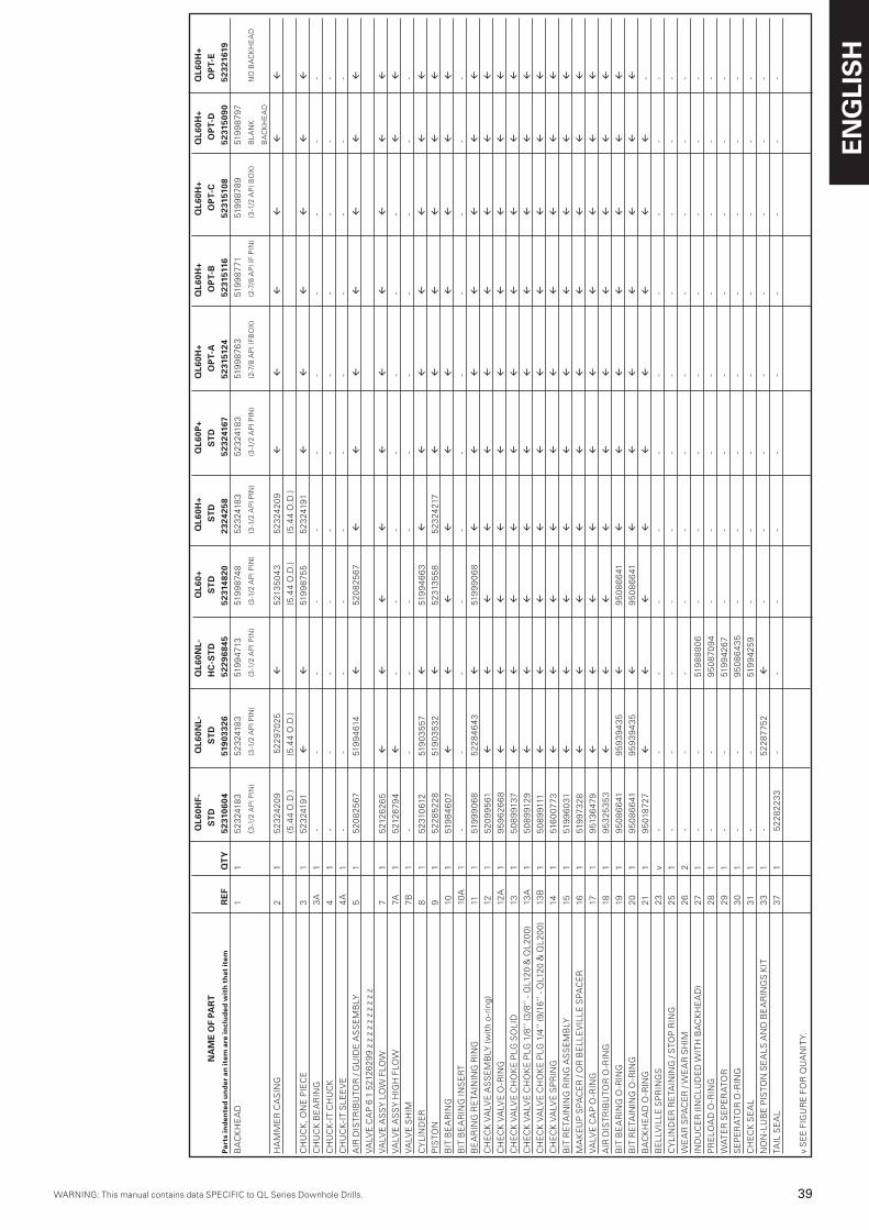
WARNING: This manual contains data SPECIFIC to QL Series Downhole Drills.WARNING: This manual contains data SPECIFIC to QL Series Downhole Drills.
ENG
LIS
H
�9WARNING: This manual contains data SPECIFIC to QL Series Downhole Drills.
Q
L60H
F-
QL6
0NL-
Q
L60N
L-
Q
L60+
Q
L60H
+ Q
L60P
+ Q
L60H
+ Q
L60H
+ Q
L60H
+ Q
L60H
+ Q
L60H
+
NA
ME
OF
PAR
T
ST
D
S
TD
H
C-S
TD
ST
D
S
TD
ST
D
O
PT-
A
OP
T-B
OP
T-C
O
PT-
D
OP
T-E
P
arts
ind
ente
d u
nd
er a
n it
em a
re in
clu
ded
wit
h th
at it
em
RE
F Q
TY
52
3106
04
5190
3326
52
2968
45
5231
4820
23
2425
8 52
3241
67
5231
5124
52
3151
16
5231
5108
52
3150
90
5232
1619
BA
CK
HE
AD
1
1
52
324
183
52
324
183
519
947
13
519
98
748
52
324
183
52
324
183
519
98
763
519
98
771
51
99
87
89
519
98
797
(3
-1/2
AP
I PIN
) (3
-1/2
AP
I PIN
) (3
-1/2
AP
I PIN
) (3
-1/2
AP
I PIN
) (3
-1/2
AP
I PIN
) (3
-1/2
AP
I PIN
) (2
-7/8
AP
I IFB
OX
) (2
-7/8
AP
I IF
PIN
) (3
-1/2
AP
I BO
X)
BL
AN
K
NO
BA
CK
HE
AD
BA
CK
HE
AD
HA
MM
ER
CA
SIN
G
2
1 5
23
242
09
52
297
025
fl
5
213
50
43
52
324
20
9 fl
fl
fl
fl
fl
fl
(5
.44
O.D
.) (5
.44
O.D
.)
(5
.44
O.D
.) (5
.44
O.D
.)
CH
UC
K, O
NE
PIE
CE
3
1
5
23
2419
1 fl
fl
51
99
875
5
52
324
191
fl
fl
fl
fl
fl
fl
CH
UC
K B
EA
RIN
G
3A
1
- -
- -
- -
- -
- -
-
CH
UC
K-I
T C
HU
CK
4
1
- -
- -
- -
- -
- -
-
CH
UC
K-I
T S
LE
EV
E
4A
1
- -
- -
- -
- -
- -
-
AIR
DIS
TR
IBU
TOR
/ G
UID
E A
SS
EM
BLY
5
1
5
20
825
67
51
99
461
4 fl
5
20
825
67
fl
fl
fl
fl
fl
fl
fl
VA
LVE
CA
P 6
1 5
212
62
99
z z
z z
z z
z z
z z
VA
LVE
AS
SY
LO
W F
LOW
7
1
5
212
62
65
fl
fl
fl
fl
fl
fl
fl
fl
fl
fl
VA
LVE
AS
SY
HIG
H F
LOW
7A
1
5
212
679
4 fl
-
- -
- -
- -
fl
fl
VA
LVE
SH
IM
7B
1
- -
- -
- -
- -
- -
-
CY
LIN
DE
R
8
1
52
310
612
51
90
35
57
fl
519
94
66
3 fl
fl
fl
fl
fl
fl
fl
PIS
TON
9
1
5
22
85
22
8
519
03
53
2 fl
5
231
35
58
5
23
2421
7 fl
fl
fl
fl
fl
fl
BIT
BE
AR
ING
10
1
51
98
46
07
fl
fl
fl
fl
fl
fl
fl
fl
fl
fl
BIT
BE
AR
ING
INS
ER
T
10A
1
- -
- -
- -
- -
- -
-
BE
AR
ING
RE
TAIN
ING
RIN
G
11
1
519
99
06
8
52
28
46
43
fl
519
99
06
8 fl
fl
fl
fl
fl
fl
fl
CH
EC
K V
ALV
E A
SS
EM
BLY
(with
o-r
ing)
12
1
5
20
99
561
fl
fl
fl
fl
fl
fl
fl
fl
fl
fl
CH
EC
K V
ALV
E O
-RIN
G
12A
1
9
59
62
66
8 fl
fl
fl
fl
fl
fl
fl
fl
fl
fl
CH
EC
K V
ALV
E C
HO
KE
PLG
SO
LID
13
1
5
08
991
37
fl
fl
fl
fl
fl
fl
fl
fl
fl
fl
CH
EC
K V
ALV
E C
HO
KE
PLG
1/8
’’ (3
/8’’
- QL1
20
& Q
L2
00
) 13
A
1
50
89
912
9 fl
fl
fl
fl
fl
fl
fl
fl
fl
fl
CH
EC
K V
ALV
E C
HO
KE
PLG
1/4
’’ (9
/16
’’ - Q
L12
0 &
QL
20
0)
13B
1
5
08
991
11
fl
fl
fl
fl
fl
fl
fl
fl
fl
fl
CH
EC
K V
ALV
E S
PR
ING
14
1
51
60
077
3 fl
fl
fl
fl
fl
fl
fl
fl
fl
fl
BIT
RE
TAIN
ING
RIN
G A
SS
EM
BLY
15
1
51
99
60
31
fl
fl
fl
fl
fl
fl
fl
fl
fl
fl
MA
KE
UP
SP
AC
ER
/ O
R B
EL
LE
VIL
LE
SP
AC
ER
16
1
51
997
32
8 fl
fl
fl
fl
fl
fl
fl
fl
fl
fl
VA
LVE
CA
P O
-RIN
G
17
1
951
36
479
fl
fl
fl
fl
fl
fl
fl
fl
fl
fl
AIR
DIS
TR
IBU
TOR
O-R
ING
18
1
9
53
253
53
fl
fl
fl
fl
fl
fl
fl
fl
fl
fl
BIT
BE
AR
ING
O-R
ING
19
1
95
08
66
41
95
93
94
35
fl
95
08
66
41
fl
fl
fl
fl
fl
fl
fl
BIT
RE
TAIN
ING
O-R
ING
2
0
1
95
08
66
41
95
93
94
35
fl
9
50
86
641
fl
fl
fl
fl
fl
fl
fl
BA
CK
HE
AD
O-R
ING
21
1
9
501
872
7 fl
fl
fl
fl
fl
fl
fl
fl
fl
-
BE
LLV
ILL
E S
PR
ING
S
23
v -
- -
- -
-
-
- -
- -
CY
LIN
DE
R R
ETA
ININ
G /
STO
P R
ING
25
1
- -
- -
- -
- -
- -
-
WE
AR
SP
AC
ER
/ W
EA
R S
HIM
2
6 2
- -
- -
- -
- -
- -
-
IND
UC
ER
(IN
CLU
DE
D W
ITH
BA
CK
HE
AD
) 27
1
- -
519
88
80
6 -
- -
- -
- -
-
PR
ELO
AD
O-R
ING
2
8
1 -
- 9
50
870
94
- -
- -
- -
- -
WA
TE
R S
EP
ER
ATO
R
29
1
- -
51
99
426
7 -
- -
- -
- -
-
SE
PE
RA
TOR
O-R
ING
3
0
1
- -
9
50
86
43
5 -
- -
- -
- -
-
CH
EC
K S
EA
L
31
1 -
-
519
942
59
- -
- -
- -
- -
NO
N-L
UB
E P
ISTO
N S
EA
LS
AN
D B
EA
RIN
GS
KIT
3
3 1
-
52
28
775
2 fl
-
- -
- -
- -
-
TAIL
SE
AL
37
1
52
28
22
33
- -
- -
- -
- -
- -
v S
EE
FIG
UR
E F
OR
QU
AN
ITY.
QL4
0-
Q
L40P
- Q
L40L
H-
Q
L50-
QL5
0-
QL5
0HC
- Q
L50H
C
QL5
5QM
- Q
L50H
F Q
L55Q
MH
F-
NA
ME
OF
PAR
T
ST
D
ST
D
ST
D
S
TD
O
PT-
A
S
TD
OP
T-A
ST
D
S
TD
S
TD
Par
ts in
den
ted
un
der
an
item
are
incl
ud
ed w
ith
that
item
RE
F Q
TY
52
1335
19
5231
5389
52
3103
98
5198
3120
52
1003
10
5210
0344
52
1013
59
5199
7591
52
2848
82
52
2848
90
BA
CK
HE
AD
1
1
521
2772
7 fl
5
231
04
30
51
991
48
7 5
210
03
28
5
210
03
85
521
013
67
519
55
771
5
1991
48
7 5
195
57
71
(2
-3/8
AP
I PIN
)
(2-3
/8 A
PI P
IN)
(3-1
/2 A
PI P
IN)
(2
-3/8
AP
I RE
GP
IN)
(3-1
/2 A
PI P
IN)
(2-3
/8 A
PI P
IN)
(3-1
/2 A
PI P
IN)
(3-1
/2 A
PI P
IN)
(3-1
/2 A
PI P
IN)
HA
MM
ER
CA
SIN
G
2
1
521
318
02
fl
52
310
414
519
9147
9
fl
fl
fl
51
95
58
05
52
28
48
09
52
28
49
32
(3
.69
O.D
.)
(3.6
9 O
.D.)
(4.6
0 O
.D.)
(4
.88
O.D
.) (4
.60
O.D
.) (4
.88
O.D
.)
CH
UC
K, O
NE
PIE
CE
3
1
5
2131
78
6
fl
52
310
422
51
991
49
5
fl
fl
fl
51
95
574
8
519
914
95
51
95
574
8
CH
UC
K B
EA
RIN
G
3A
-
-
-
-
-
-
-
-
-
-
-
CH
UC
K-I
T C
HU
CK
4
1
-
-
-
-
-
-
-
-
-
-
CH
UC
K-I
T S
LE
EV
E
4A
1
-
-
-
-
-
-
-
-
-
-
AIR
DIS
TR
IBU
TOR
/ G
UID
E A
SS
Y.
5
1
521
3175
2
fl
fl
51
793
69
3
fl
fl
fl
fl
fl
fl
VA
LVE
CA
P
6
1
-
-
- 51
793
68
5
fl
fl
fl
fl
fl
fl
VA
LVE
AS
SY
LO
W F
LOW
7
1
-
-
-
5
20
82
98
9
fl
fl
fl
fl
fl
fl
VA
LVE
AS
SY
HIG
H F
LOW
7
A
1
521
33
53
5 fl
-
52
297
67
8
fl
fl
fl
fl
fl
fl
VA
LVE
SH
IM
7B
1
5
213
82
86
fl
fl
-
-
-
-
-
-
-
CY
LIN
DE
R
8
1
5171
637
1 fl
fl
519
970
88
fl
fl
fl
fl
fl
fl
PIS
TON
9
1
5
2131
760
fl
fl
51
99
65
51
fl
fl
fl
fl
521
23
50
2
fl
BIT
BE
AR
ING
1
0
1
521
317
78
fl
fl
51
99
65
69
fl
fl
fl
fl
fl
fl
BE
AR
ING
RE
TAIN
ING
RIN
G
11
1
5
2131
810
fl
fl
519
870
14
fl
fl
fl
fl
fl
fl
CH
EC
K V
ALV
E A
SS
EM
BLY
(with
o-r
ing)
1
2 1
5
2127
73
5 fl
fl
521
156
64
fl
fl
fl
fl
fl
fl
C
HE
CK
VA
LVE
O-R
ING
1
2A
1
-
-
-
9
59
627
42
fl
fl
fl
fl
fl
fl
CH
EC
K V
ALV
E C
HO
KE
PLG
SO
LID
1
3
1
521
318
28
fl
fl
5
08
991
37
fl
fl
fl
fl
fl
fl
CH
EC
K V
ALV
E C
HO
KE
PLG
1/8
’’ (3
/8’’
- QL1
20
& Q
L2
00
) 1
3A
1
-
-
-
5
08
991
29
fl
fl
fl
fl
fl
fl
CH
EC
K V
ALV
E C
HO
KE
PLG
1/4
’’ (9
/16
’’ - Q
L12
0 &
QL
20
0)
13
B
1
-
-
-
50
89
9111
fl
fl
fl
fl
fl
fl
CH
EC
K V
ALV
E S
PR
ING
1
4
1
-
-
- 51
85
7274
fl
fl
fl
fl
fl
fl
BIT
RE
TAIN
ING
RIN
G A
SS
EM
BLY
1
5
1
519
88
947
fl
fl
519
870
06
fl
fl
fl
fl
fl
fl
MA
KE
UP
SP
AC
ER
1
6
1
-
-
-
519
9724
5
fl
fl
fl
fl
fl
fl
VA
LVE
CA
P O
-RIN
G
17
1
9
513
641
2 fl
fl
951
36
43
8
fl
fl
fl
fl
fl
fl
AIR
DIS
TR
IBU
TOR
O-R
ING
1
8
1
951
36
55
2 fl
fl
951
3721
2
fl
fl
fl
fl
fl
fl
BIT
BE
AR
ING
O-R
ING
1
9
1
95
08
631
0 fl
fl
95
08
63
51
fl
fl
fl
fl
fl
fl
BIT
RE
TAIN
ING
O-R
ING
2
0
1
95
08
631
0 fl
fl
95
08
63
51
fl
fl
fl
fl
fl
fl
BA
CK
HE
AD
O-R
ING
2
1
1
95
018
719
fl
fl
9
50
28
45
2
fl
fl
fl
fl
fl
fl
BE
LLV
ILL
E S
PR
ING
S
23
v
-
-
-
-
-
-
-
-
-
-
BE
LLV
ILL
E C
AS
SE
TT
E (Q
L4
ON
LY)
24
1
-
-
-
-
-
-
-
-
-
-
CY
LIN
DE
R R
ETA
ININ
G R
ING
2
5
1
521
3181
0 fl
fl
-
-
-
-
-
-
-
IND
UC
ER
2
7
1
-
-
-
-
- 5
210
03
69
fl
-
-
-
PR
ELO
AD
O-R
ING
2
8
1
-
-
-
-
-
9
50
870
60
fl
-
-
-
WA
TE
R S
EP
ER
ATO
R
29
1
-
-
-
-
-
521
00
377
fl
-
-
-
SE
PE
RA
TOR
O-R
ING
3
0 1
-
-
-
-
-
95
08
625
2
fl
-
-
-
CH
EC
K S
EA
L
31
1
-
-
-
-
-
521
00
39
3
fl
-
-
-
v S
EE
FIG
UR
E F
OR
QU
AN
ITY.
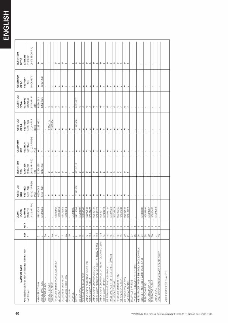
ENG
LIS
H
40 WARNING: This manual contains data SPECIFIC to QL Series Downhole Drills.WARNING: This manual contains data SPECIFIC to QL Series Downhole Drills.
Q
L60+
Q
L65+
QM
Q
L65H
+QM
Q
L65P
+QM
Q
L65+
QM
Q
L65H
+QM
Q
L65H
+QM
Q
L65H
+QM
N
AM
E O
F PA
RT
HC
-ST
D
ST
D
ST
D
ST
D
OP
T-A
O
PT-
A
OP
T-B
O
PT-
CP
arts
ind
ente
d u
nd
er a
n it
em a
re in
clu
ded
wit
h th
at it
em
RE
F
QT
Y
5231
4838
52
3151
32
5232
4266
52
3241
75
5231
5199
52
3290
83
5231
5207
52
3152
15
BA
CK
HE
AD
1
1
519
947
13
519
9124
8 5
23
2424
1 5
23
2424
1 51
991
248
52
324
241
NO
51
99
88
21
(3
-1/2
AP
I PIN
) (3
-1/2
AP
I RE
G
(3-1
/2 A
PI R
EG
(3
-1/2
AP
I RE
G
2-7/
8 A
PI I
F 2-
7/8
AP
I IF
BA
CK
HE
AD
(3
-1/2
BE
CO
PIN
)
PIN
) P
IN)
PIN
) B
OX
) B
OX
)
HA
MM
ER
CA
SIN
G
2 1
5
213
50
43
5
22
916
63
5
23
242
25
fl
52
291
66
3 5
22
916
63
fl
fl
CH
UC
K, O
NE
PIE
CE
3
1
5
199
875
5
519
912
22
5
23
242
33
fl
-
52
324
225
5
23
242
33
fl
CH
UC
K B
EA
RIN
G
3A
1
-
- -
- -
- -
-
CH
UC
K-I
T C
HU
CK
4
1
- fl
fl
fl
5
1997
419
fl
- -
CH
UC
K-I
T S
LE
EV
E
4A
1
-
fl
fl
fl
519
85
55
4 fl
-
-
AIR
DIS
TR
IBU
TOR
/ G
UID
E A
SS
EM
BLY
5
1
5
20
825
67
fl
fl
fl
fl
fl
fl
fl
VA
LVE
CA
P
6
1
521
26
29
9 fl
fl
fl
fl
fl
fl
fl
VA
LVE
AS
SY
LO
W F
LOW
7
1
5
212
62
65
fl
fl
fl
fl
fl
fl
fl
VA
LVE
AS
SY
HIG
H F
LOW
7A
1
5
212
679
4 fl
fl
fl
fl
fl
fl
fl
VA
LVE
SH
IM
7B
1
- -
- -
fl
- -
-
CY
LIN
DE
R
8 1
5
199
46
63
fl
fl
fl
fl
fl
fl
fl
PIS
TON
9
1
52
313
55
8 5
231
35
58
52
324
217
fl
52
313
55
8 5
23
2421
7 fl
fl
BIT
BE
AR
ING
10
1
5
198
46
07
fl
fl
fl
fl
fl
fl
fl
BE
AR
ING
RE
TAIN
ING
RIN
G
11
1
519
99
06
8 fl
fl
fl
fl
fl
fl
fl
CH
EC
K V
ALV
E A
SS
EM
BLY
(with
o-r
ing)
12
1
5
20
99
561
fl
fl
fl
fl
fl
fl
fl
CH
EC
K V
ALV
E O
-RIN
G
12A
1
9
59
62
66
8 fl
fl
fl
fl
fl
fl
fl
CH
EC
K V
ALV
E C
HO
KE
PLG
SO
LID
13
1
5
08
991
37
fl
fl
fl
fl
fl
fl
fl
CH
EC
K V
ALV
E C
HO
KE
PLG
1/8
’’ (3
/8’’
- QL1
20
& Q
L2
00
) 13
A
1
50
89
912
9 fl
fl
fl
fl
fl
fl
fl
CH
EC
K V
ALV
E C
HO
KE
PLG
1/4
’’ (9
/16
’’ - Q
L12
0 &
QL
20
0)
13B
1
5
08
991
11
fl
fl
fl
fl
fl
fl
fl
CH
EC
K V
ALV
E S
PR
ING
14
1
5
160
077
3 fl
fl
fl
fl
fl
fl
fl
BIT
RE
TAIN
ING
RIN
G A
SS
EM
BLY
15
1
5
199
60
31
fl
fl
fl
fl
fl
fl
fl
MA
KE
UP
SP
AC
ER
/ O
R B
EL
LE
VIL
LE
SP
AC
ER
16
1
5
1997
32
8 fl
fl
fl
fl
fl
fl
fl
VA
LVE
CA
P O
-RIN
G
17
1
951
36
479
fl
fl
fl
fl
fl
fl
fl
AIR
DIS
TR
IBU
TOR
O-R
ING
18
1
9
53
253
53
fl
fl
fl
fl
fl
fl
fl
BIT
BE
AR
ING
O-R
ING
19
1
9
50
86
641
fl
fl
fl
fl
fl
fl
fl
BIT
RE
TAIN
ING
O-R
ING
2
0 1
9
50
86
641
fl
fl
fl
fl
fl
fl
fl
BA
CK
HE
AD
O-R
ING
21
1
9
501
872
7
fl
fl
fl
fl
fl
fl
fl
BE
LLV
ILL
E S
PR
ING
S
23
v
- -
- -
- -
- -
CY
LIN
DE
R R
ETA
ININ
G /
STO
P R
ING
25
1
-
- -
- -
- -
-
WE
AR
SP
AC
ER
/ W
EA
R S
HIM
(QL
4 &
QL
20
0 O
NLY
) 2
6 2
-
- -
- -
- -
-
IND
UC
ER
(IN
CLU
DE
D W
ITH
BA
CK
HE
AD
) 27
1
5
198
88
06
- -
- -
- -
-
PR
ELO
AD
O-R
ING
2
8 1
9
50
870
94
- -
- -
- -
-
WA
TE
R S
EP
ER
ATO
R
29
1
519
942
67
- -
- -
- -
-
SE
PE
RA
TOR
O-R
ING
3
0 1
9
50
86
43
5 -
- -
- -
- -
CH
EC
K S
EA
L
31
1
519
942
59
- -
- -
- -
-
NO
N-L
UB
E P
ISTO
N S
EA
LS
AN
D B
EA
RIN
GS
KIT
3
3 1
-
- -
- -
- -
-
v S
EE
FIG
UR
E F
OR
QU
AN
ITY.
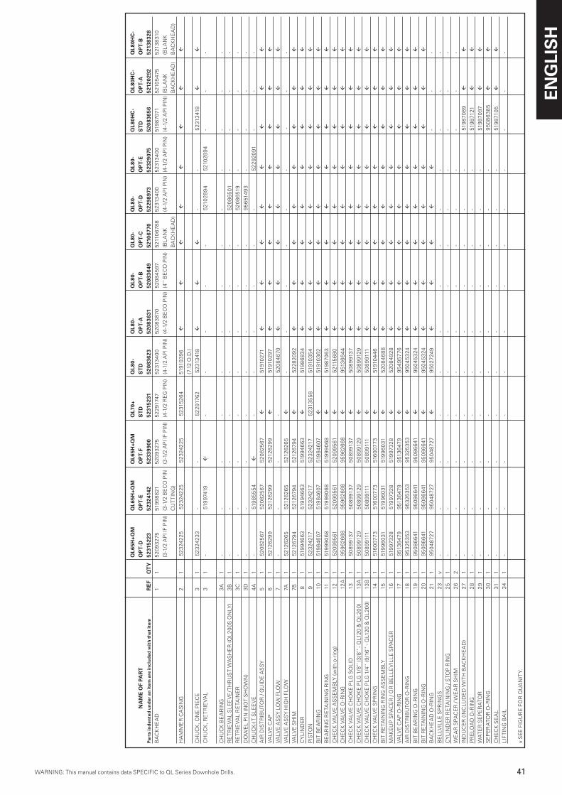
WARNING: This manual contains data SPECIFIC to QL Series Downhole Drills.WARNING: This manual contains data SPECIFIC to QL Series Downhole Drills.
ENG
LIS
H
41WARNING: This manual contains data SPECIFIC to QL Series Downhole Drills.
Q
L65H
+QM
Q
L65H
+QM
Q
L65H
+QM
Q
L70+
Q
L80-
Q
L80-
Q
L80-
Q
L80-
Q
L80-
Q
L80-
Q
L80H
C-
QL8
0HC
- Q
L80H
C-
NA
ME
OF
PAR
T
O
PT-
D
OP
T-E
OP
T-F
ST
D
ST
D
OP
T-A
O
PT-
B
OP
T-C
O
PT-
D
OP
T-E
ST
D
OP
T-A
O
PT-
BP
arts
ind
ente
d u
nd
er a
n it
em a
re in
clu
ded
wit
h th
at it
em
RE
F Q
TY
52
3152
23
5232
4142
52
3399
00
5231
5231
52
0836
23
5208
3631
52
0836
49
5210
6770
52
2989
73
5232
9075
52
0836
56
5212
0292
52
1383
28B
AC
KH
EA
D
1 1
5
20
93
275
519
98
821
5
20
93
275
52
291
747
52
313
40
0 5
20
83
870
5
20
84
597
5
2110
67
88
52
313
40
0 5
231
34
00
519
870
71
521
05
475
521
38
310
(3
-1/2
AP
I IF
PIN
) (3
-1/2
BE
CO
PIN
(3
-1/2
AP
I IF
PIN
) (4
-1/2
RE
G P
IN)
(4-1
/2 A
PI P
IN)
(4-1
/2 B
EC
O P
IN)
(4’’
BE
CO
PIN
) (B
LA
NK
(4
-1/2
AP
I PIN
) (4
-1/2
AP
I PIN
) (4
-1/2
AP
I PIN
) (B
LA
NK
(B
LA
NK
CU
TT
ING
)
BA
CK
HE
AD
)
BA
CK
HE
AD
) B
AC
KH
EA
D)
HA
MM
ER
CA
SIN
G
2 1
5
23
242
25
52
324
225
5
23
242
25
52
315
26
4 51
910
39
6 fl
fl
fl
fl
fl
fl
fl
fl
(7
.12
O.D
.)
CH
UC
K, O
NE
PIE
CE
3
1
52
324
23
3 -
-
52
291
762
52
313
418
fl
fl
fl
- -
52
313
418
fl
fl
CH
UC
K, R
ET
RIE
VA
L
3 1
-
519
9741
9 fl
-
- -
- -
521
02
89
4 5
210
28
94
- -
-
CH
UC
K B
EA
RIN
G
3A
1
-
- -
- -
- -
- -
- -
- -
RE
TR
IEV
AL
SL
EE
VE
/TH
RU
ST
WA
SH
ER
(QL
20
0S
ON
LY)
3B
1
-
- -
- -
- -
- 5
20
86
501
-
- -
-
RE
TR
IEV
AL
RE
TAIN
ER
3
C
1
- -
- -
- -
- -
52
08
651
9 -
- -
-
DO
WE
L P
IN (N
OT
SH
OW
N)
3D
1
-
- -
- -
- -
- 9
56
514
93
- -
- -
CH
UC
K-I
T S
LE
EV
E
4A
1
-
519
85
55
4 fl
-
- -
- -
- 5
22
92
091
-
- -
AIR
DIS
TR
IBU
TOR
/ G
UID
E A
SS
Y
5 1
5
20
825
67
5
20
825
67
52
08
256
7 fl
5
1910
271
fl
fl
fl
fl
fl
fl
fl
fl
VA
LVE
CA
P
6 1
5
212
62
99
521
26
29
9 5
212
62
99
fl
519
102
97
fl
fl
fl
fl
fl
fl
fl
fl
VA
LVE
AS
SY
LO
W F
LOW
7
1
- -
- -
52
08
46
70
fl
fl
fl
fl
fl
fl
fl
fl
VA
LVE
AS
SY
HIG
H F
LOW
7A
1
5
212
62
65
521
26
26
5 5
212
62
65
fl
- -
- -
- -
-
- -
VA
LVE
SH
IM
7B
1
521
26
794
521
26
794
5
212
679
4 fl
5
22
82
09
2 fl
fl
fl
fl
fl
fl
fl
fl
CY
LIN
DE
R
8
1
519
94
66
3 5
199
46
63
519
94
66
3 fl
5
198
68
34
fl
fl
fl
fl
fl
fl
fl
fl
PIS
TON
9
1
5
23
2421
7 5
23
2421
7 5
23
2421
7 5
231
35
58
519
103
54
fl
fl
fl
fl
fl
fl
fl
fl
BIT
BE
AR
ING
1
0 1
5
198
46
07
519
84
607
5
198
46
07
fl
519
103
62
fl
fl
fl
fl
fl
fl
fl
fl
BE
AR
ING
RE
TAIN
ING
RIN
G
11
1
519
99
06
8 5
199
90
68
519
99
06
8 fl
5
198
706
3 fl
fl
fl
fl
fl
fl
fl
fl
CH
EC
K V
ALV
E A
SS
EM
BLY
(with
o-r
ing)
1
2 1
5
20
99
561
5
20
99
561
5
20
99
561
fl
5
2115
68
0 fl
fl
fl
fl
fl
fl
fl
fl
CH
EC
K V
ALV
E O
-RIN
G
12
A
1
95
96
26
68
9
59
62
66
8 9
59
62
66
8 fl
9
513
66
44
fl
fl
fl
fl
fl
fl
fl
fl
CH
EC
K V
ALV
E C
HO
KE
PLG
SO
LID
1
3
1
50
89
9137
5
08
991
37
50
89
9137
fl
5
08
991
37
fl
fl
fl
fl
fl
fl
fl
fl
CH
EC
K V
ALV
E C
HO
KE
PLG
1/8
’’ (3
/8’’
- QL1
20
& Q
L2
00
) 1
3A
1
5
08
991
29
50
89
912
9 5
08
991
29
fl
50
89
912
9 fl
fl
fl
fl
fl
fl
fl
fl
CH
EC
K V
ALV
E C
HO
KE
PLG
1/4
’’ (9
/16
’’ - Q
L12
0 &
QL
20
0)
13
B
1
50
89
9111
5
08
991
11
50
89
9111
fl
5
08
991
11
fl
fl
fl
fl
fl
fl
fl
fl
CH
EC
K V
ALV
E S
PR
ING
1
4
1
516
007
73
5
160
077
3
516
007
73
fl
519
104
46
fl
fl
fl
fl
fl
fl
fl
fl
BIT
RE
TAIN
ING
RIN
G A
SS
EM
BLY
1
5 1
5
199
60
31
519
96
031
5
199
60
31
fl
52
08
46
88
fl
fl
fl
fl
fl
fl
fl
fl
MA
KE
UP
SP
AC
ER
/ O
R B
EL
LE
VIL
LE
SP
AC
ER
1
6 1
5
1997
32
8 5
1997
32
8
519
973
28
fl
52
08
49
28
fl
fl
fl
fl
fl
fl
fl
fl
VA
LVE
CA
P O
-RIN
G
17
1
951
36
479
951
36
479
951
36
479
fl
95
49
57
76
fl
fl
fl
fl
fl
fl
fl
fl
AIR
DIS
TR
IBU
TOR
O-R
ING
1
8 1
9
53
253
53
95
325
35
3 9
53
253
53
fl
95
04
53
24
fl
fl
fl
fl
fl
fl
fl
fl
BIT
BE
AR
ING
O-R
ING
1
9 1
9
50
86
641
9
50
86
641
9
50
86
641
fl
9
50
45
324
fl
fl
fl
fl
fl
fl
fl
fl
BIT
RE
TAIN
ING
O-R
ING
2
0 1
9
50
86
641
9
50
86
641
9
50
86
641
fl
9
50
45
324
fl
fl
fl
fl
fl
fl
fl
fl
BA
CK
HE
AD
O-R
ING
2
1 1
9
50
48
727
95
04
872
7 9
50
48
727
fl
95
027
249
fl
fl
fl
fl
fl
- -
-
BE
LLV
ILL
E S
PR
ING
S
23
v
- -
- -
- -
- -
- -
- -
-
CY
LIN
DE
R R
ETA
ININ
G /
STO
P R
ING
2
5 1
-
- -
- -
- -
- -
- -
- -
WE
AR
SP
AC
ER
/ W
EA
R S
HIM
2
6 2
-
- -
- -
- -
- -
- -
- -
IND
UC
ER
(IN
CLU
DE
D W
ITH
BA
CK
HE
AD
) 2
7 1
-
- -
- -
- -
- -
- 5
198
708
9 fl
fl
PR
ELO
AD
O-R
ING
2
8 1
-
- -
- -
- -
- -
- 5
198
7121
fl
fl
WA
TE
R S
EP
ER
ATO
R
29
1
- -
- -
- -
- -
- -
519
870
97
fl
fl
SE
PE
RA
TOR
O-R
ING
3
0 1
-
- -
- -
- -
- -
- 9
50
86
38
5 fl
fl
CH
EC
K S
EA
L 3
1 1
-
- -
- -
- -
- -
- 5
198
710
5 fl
fl
LIF
TIN
G B
AIL
3
4 1
-
- -
- -
- -
- -
- -
- -
v S
EE
FIG
UR
E F
OR
QU
AN
ITY.
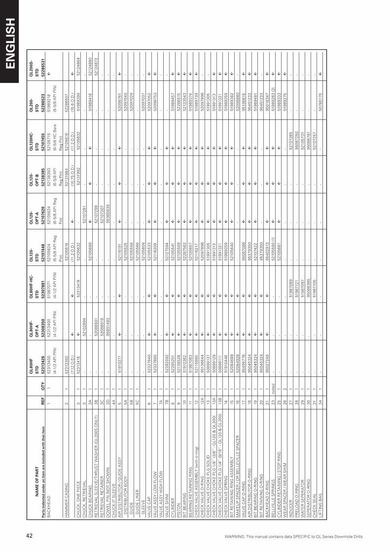
ENG
LIS
H
42 WARNING: This manual contains data SPECIFIC to QL Series Downhole Drills.WARNING: This manual contains data SPECIFIC to QL Series Downhole Drills.
Q
L80H
F Q
L80H
F-
QL8
0HF-
HC
- Q
L120
- Q
L120
- Q
L120
- Q
L120
HC
- Q
L200
- Q
L200
S-
NA
ME
OF
PAR
T
S
TD
O
PT-
A
ST
D
ST
D
OP
T-A
O
PT-
B
ST
D
ST
D
ST
DP
arts
ind
ente
d u
nd
er a
n it
em a
re in
clu
ded
wit
h th
at it
em
RE
F Q
TY
52
3134
26
5230
8350
52
3078
81
5210
7448
52
1076
20
5213
8385
52
1074
55
5228
6523
52
2865
31
BA
CK
HE
AD
1
1
52
313
40
0 5
231
34
00
519
870
71
521
05
624
5
210
56
24
521
38
39
3 5
210
571
5 51
98
921
8 fl
(4
-1/2
AP
I PIN
) (4
-1/2
AP
I PIN
) (4
-1/2
AP
I PIN
) (6
-5/8
AP
I Reg
(6
-5/8
AP
I Reg
(6
-5/8
AP
I (6
-5/8
HC
Bar
e (8
-5/8
AP
I PIN
)
Pin
) P
in)
Reg
Pin
) R
eg P
in)
HA
MM
ER
CA
SIN
G
2
1 5
231
33
92
521
05
616
5
2131
98
4 5
210
561
6 5
22
86
507
(7
.12
O.D
.) fl
fl
(1
1.2
O.D
.) fl
(1
0.75
O.D
.) (1
1.2
O.D
.) (1
5.6
O.D
.) fl
CH
UC
K, O
NE
PIE
CE
3
1
5
231
341
8 fl
5
231
341
8 5
210
56
32
- 5
2131
99
2 5
210
56
32
519
89
39
0 5
2124
86
4
CH
UC
K, R
ET
RIE
VA
L 3
1 -
521
02
89
4 -
- 5
2107
281
-
- -
-
CH
UC
K B
EA
RIN
G
3A
1
- -
- 5
210
56
99
fl
fl
fl
5
198
941
6 5
2124
88
0
RE
TR
IEV
AL
SL
EE
VE
/TH
RU
ST
WA
SH
ER
(QL
20
0S
ON
LY)
3B
1
- 5
20
86
501
-
- 5
2107
29
9 -
- -
521
248
72
RE
TR
IEV
AL
RE
TAIN
ER
3
C
1 -
52
08
651
9 -
- 5
2107
307
-
- -
-
DO
WE
L P
IN (N
OT
SH
OW
N)
3D
1
- 9
56
514
93
- -
95
36
58
39
- -
- -
CH
UC
K-I
T S
LE
EV
E
4A
1
- -
- -
- -
- -
-
AIR
DIS
TR
IBU
TOR
/ G
UID
E A
SS
Y
5
1 5
1910
271
fl
fl
521
1619
1 fl
fl
fl
5
20
98
761
fl
D
IST
RIB
UTO
R B
OD
Y
5A
1
-
- -
521
05
525
-
- -
52
097
04
5 -
G
UID
E
5B
1
-
-
-
5
210
55
58
- -
- 5
20
970
29
-
G
UID
E L
INE
R
5C
1
- -
- 5
210
55
66
- -
- -
-
S
LE
EV
E
- -
- 5
210
56
08
- -
- 5
20
970
37
-
VA
LVE
CA
P
6
1
52
327
64
0 fl
fl
5
210
55
33
fl
fl
fl
52
097
05
2 fl
VA
LVE
AS
SY
LO
W F
LOW
7
1
52
327
66
5 fl
fl
5
2116
20
9 fl
fl
fl
5
20
98
753
fl
VA
LVE
AS
SY
HIG
H F
LOW
7A
1
-
- -
- -
- -
- -
VA
LVE
SH
IM
7B
1
52
28
20
92
fl
fl
521
275
94
fl
fl
fl
- -
CY
LIN
DE
R
8 1
52
28
525
1 fl
fl
5
210
55
41
fl
fl
fl
519
89
45
7 fl
PIS
TON
9
1
521
38
52
6 fl
fl
5
210
55
09
fl
fl
fl
52
28
651
5 fl
BIT
BE
AR
ING
10
1
519
103
62
fl
fl
52
28
756
2 fl
fl
fl
5
213
35
43
fl
BE
AR
ING
RE
TAIN
ING
RIN
G
11
1 5
198
706
3 fl
fl
5
210
56
57
fl
fl
fl
519
89
374
fl
CH
EC
K V
ALV
E A
SS
EM
BLY
(with
o-r
ing)
12
1
521
156
80
fl
fl
521
1621
7 fl
fl
fl
5
198
973
9 fl
CH
EC
K V
ALV
E O
-RIN
G
12A
1
9
513
66
44
fl
fl
52
097
89
6
fl
fl
fl
52
097
89
6 -
CH
EC
K V
ALV
E C
HO
KE
PLG
SO
LID
13
1
50
89
9137
fl
fl
5
1991
30
5 fl
fl
fl
5
1991
30
5 -
CH
EC
K V
ALV
E C
HO
KE
PLG
1/8
’’ (3
/8’’
- QL1
20
& Q
L2
00
) 13
A
1
50
89
912
9 fl
fl
5
1991
313
fl
fl
fl
519
9131
3 fl
CH
EC
K V
ALV
E C
HO
KE
PLG
1/4
’’ (9
/16
’’ - Q
L12
0 &
QL
20
0)
13B
1
50
89
9111
fl
fl
5
1991
321
fl
fl
fl
5
1991
321
fl
CH
EC
K V
ALV
E S
PR
ING
14
1
519
104
46
fl
fl
519
89
259
fl
fl
fl
519
89
259
fl
BIT
RE
TAIN
ING
RIN
G A
SS
EM
BLY
15
1
5
20
84
68
8 fl
fl
5
210
56
40
fl
fl
fl
5
198
93
82
fl
MA
KE
UP
SP
AC
ER
/ O
R B
EL
LE
VIL
LE
SP
AC
ER
16
1
5
20
84
92
8 fl
fl
-
- -
- 5
20
98
86
0 -
VA
LVE
CA
P O
-RIN
G
17
1
95
49
57
76
fl
fl
95
08
708
6 fl
fl
fl
9
513
681
8 fl
AIR
DIS
TR
IBU
TOR
O-R
ING
18
1
95
04
53
24
fl
fl
95
379
35
0 fl
fl
fl
9
54
512
33
fl
BIT
BE
AR
ING
O-R
ING
19
1
9
50
45
324
fl
fl
5
2107
422
fl
fl
fl
519
89
481
fl
BIT
RE
TAIN
ING
O-R
ING
2
0
1
95
04
53
24
fl
fl
95
379
35
0 -
- -
95
451
23
3 -
BA
CK
HE
AD
O-R
ING
21
1
9
50
2724
9
fl
fl
95
40
291
3 fl
fl
fl
9
501
83
47
fl
BE
LLV
ILL
E S
PR
ING
S
23
n
oted
-
- -
521
05
59
0 (1
) fl
fl
fl
5
198
92
83
(2)
fl
CY
LIN
DE
R R
ETA
ININ
G /
STO
P R
ING
25
1
- -
- 5
210
56
81
fl
fl
fl
519
89
33
3 fl
WE
AR
SP
AC
ER
/ W
EA
R S
HIM
2
6
2 -
- -
- -
- -
519
89
275
fl
IND
UC
ER
27
1
- -
519
870
89
- -
- 5
2107
26
5 -
-
PR
ELO
AD
O-R
ING
2
8
1 -
- 5
198
7121
-
- -
95
08
725
0 -
-
WA
TE
R S
EP
ER
ATO
R
29
1
-
- 5
198
7097
-
- -
521
05
731
-
-
SE
PE
RA
TOR
O-R
ING
3
0
1
-
- 9
50
86
38
5 -
- -
95
08
67
81
- -
CH
EC
K S
EA
L
31
1
- -
519
871
05
- -
- 5
2107
257
- -
LIF
TIN
G B
AIL
3
4
1
-
-
-
-
-
-
-
507
801
70
fl
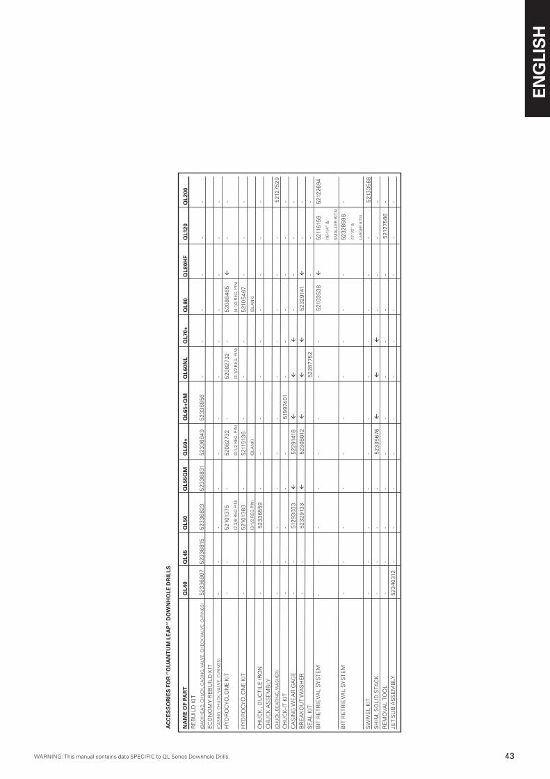
WARNING: This manual contains data SPECIFIC to QL Series Downhole Drills.WARNING: This manual contains data SPECIFIC to QL Series Downhole Drills.
ENG
LIS
H
4�WARNING: This manual contains data SPECIFIC to QL Series Downhole Drills.
AC
CE
SS
OR
IES
FO
R ‘’
QU
AN
TU
M L
EA
P’’
DO
WN
HO
LE D
RIL
LS
NA
ME
OF
PAR
T Q
L40
Q
L45
Q
L50
Q
L55Q
M
QL6
0+
QL6
5+Q
M
QL6
0NL
Q
L70+
Q
L80
Q
L80H
F
QL1
20
Q
L200
R
EB
UIL
D K
IT
(BA
CK
HE
AD
, CH
UC
K, C
AS
ING
, VA
LVE
, CH
EC
K V
ALV
E, O
-RIN
GS
) 5
23
36
807
5
23
36
815
5
23
36
82
3
52
33
68
31
52
33
68
49
5
23
36
85
6 -
- -
-
-
- E
CO
NO
MY
RE
BU
ILD
KIT
(CA
SIN
G, C
HU
CK
, VA
LVE
, O-R
ING
S)
- -
- -
- -
- -
- -
-
-
HY
DR
OC
YC
LON
E K
IT
- -
521
0137
5 -
52
08
273
2 -
52
08
273
2 -
52
08
84
65
fl
-
-
(2
-3/8
RE
G P
IN)
(3
-1/2
RE
G. P
IN)
(3
-1/2
RE
G. P
IN)
(4
-1/2
RE
G. P
IN)
HY
DR
OC
YC
LON
E K
IT
- -
521
013
83
- 5
2115
136
- -
- 5
210
54
67
-
-
-
(3-1
/2 R
EG
PIN
)
(BL
AN
K)
(B
LA
NK
)
CH
UC
K ,
DU
CT
ILE
IRO
N
- -
52
33
65
59
- -
- -
- -
-
-
- C
HU
CK
AS
SE
MB
LY
(CH
UC
K, B
EA
RIN
G, W
AS
HE
R)
- -
- -
- -
- -
- -
-
5
2127
52
9C
HU
CK
-IT
KIT
-
- -
- -
519
974
01
- -
- -
-
-
CA
SIN
G W
EA
R G
AG
E
- -
512
93
03
3 fl
5
22
9141
6 fl
fl
fl
-
-
-
- B
RE
AK
OU
T W
AS
HE
R
- -
52
32
913
3 fl
5
23
08
012
fl
fl
fl
52
32
9141
fl
-
- S
EA
L K
IT
52
28
775
2
-
-
-
BIT
RE
TR
IEV
AL
SY
ST
EM
-
- -
- -
- -
- 5
210
35
38
fl
521
1615
9
521
22
69
4
(1
6-1
/4’’
&
SM
AL
LE
R B
ITS
) B
IT R
ET
RIE
VA
L S
YS
TE
M
- -
- -
- -
- -
- -
5
23
28
59
8
-
(1
7-1/
2’’
&
LA
RG
ER
BIT
S)
SW
IVE
L K
IT
- -
- -
- -
- -
- -
-
5
213
35
68
SH
IM, S
OL
ID S
TAC
K
- -
- -
52
33
56
76
fl
fl
fl
- -
-
-
RE
MO
VA
L TO
OL
- -
- -
- -
- -
- -
5
2127
58
6
- JE
T S
UB
AS
SE
MB
LY
52
34
031
2 -
- -
- -
- -
- -
-
-

Atlas Copco Secoroc ABBox 521, SE-7�7 25 Fagersta, Sweden
Phone: +46 22� 461 00E-mail: [email protected]
www.atlascopco.com
9852
186
4 01
- Q
L
2006
.07
R
elat
era
Related Documents