What is a Capacitor? Capacitors in General Ceramic Capacitors Tantalum Capacitors Electronics Corporation P. O. Box 5928 Greenville, SC 29606 Phone (864) 963-6300 Fax (864) 963-6521 www.kemet.com F-2856E 1-96 Reprinted 6-01

Welcome message from author
This document is posted to help you gain knowledge. Please leave a comment to let me know what you think about it! Share it to your friends and learn new things together.
Transcript
8/6/2019 Sec5 Capacitor
http://slidepdf.com/reader/full/sec5-capacitor 1/12
8/6/2019 Sec5 Capacitor
http://slidepdf.com/reader/full/sec5-capacitor 2/12
PART I
FUNDAMENTALS FOR ALL CAPACITORS
This bulletin describes the basic characteristics of KEMET
capacitors. Before examining all the details relating to KEMET
products, here are some of the basics of all capacitors and then
of the major types sold under the KEMET brands: solid tanta-
lum and monolithic ceramic.
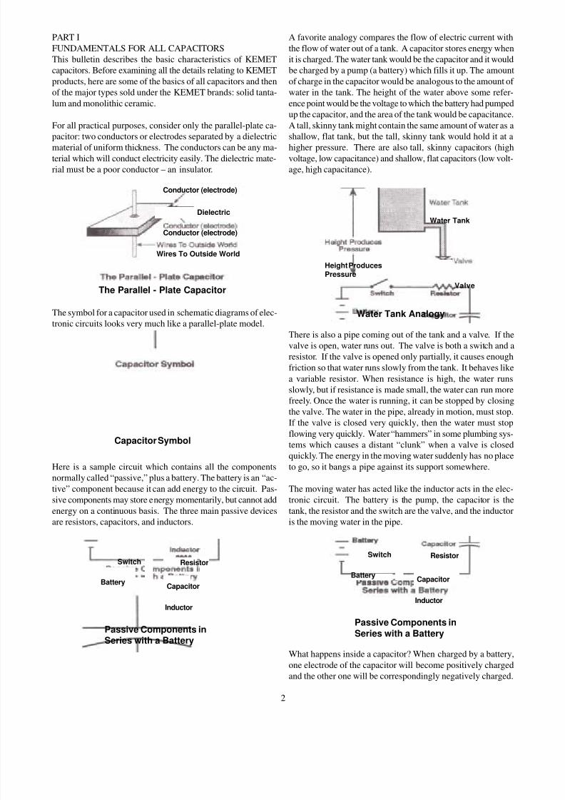
For all practical purposes, consider only the parallel-plate ca-
pacitor: two conductors or electrodes separated by a dielectricmaterial of uniform thickness. The conductors can be any ma-
terial which will conduct electricity easily. The dielectric mate-
rial must be a poor conductor – an insulator.
The symbol for a capacitor used in schematic diagrams of elec-
tronic circuits looks very much like a parallel-plate model.
Here is a sample circuit which contains all the components
normally called “passive,” plus a battery. The battery is an “ac-
tive” component because it can add energy to the circuit. Pas-
sive components may store energy momentarily, but cannot add
energy on a continuous basis. The three main passive devices
are resistors, capacitors, and inductors.
A favorite analogy compares the flow of electric current with
the flow of water out of a tank. A capacitor stores energy when
it is charged. The water tank would be the capacitor and it would
be charged by a pump (a battery) which fills it up. The amount
of charge in the capacitor would be analogous to the amount of
water in the tank. The height of the water above some refer-
ence point would be the voltage to which the battery had pumped
up the capacitor, and the area of the tank would be capacitance.
A tall, skinny tank might contain the same amount of water as a
shallow, flat tank, but the tall, skinny tank would hold it at ahigher pressure. There are also tall, skinny capacitors (high
voltage, low capacitance) and shallow, flat capacitors (low volt-
age, high capacitance).
There is also a pipe coming out of the tank and a valve. If the
valve is open, water runs out. The valve is both a switch and a
resistor. If the valve is opened only partially, it causes enough
friction so that water runs slowly from the tank. It behaves like
a variable resistor. When resistance is high, the water runs
slowly, but if resistance is made small, the water can run more
freely. Once the water is running, it can be stopped by closing
the valve. The water in the pipe, already in motion, must stop.
If the valve is closed very quickly, then the water must stopflowing very quickly. Water “hammers” in some plumbing sys-
tems which causes a distant “clunk” when a valve is closed
quickly. The energy in the moving water suddenly has no place
to go, so it bangs a pipe against its support somewhere.
The moving water has acted like the inductor acts in the elec-
tronic circuit. The battery is the pump, the capacitor is the
tank, the resistor and the switch are the valve, and the inductor
is the moving water in the pipe.
What happens inside a capacitor? When charged by a battery,
one electrode of the capacitor will become positively charged
and the other one will be correspondingly negatively charged.
2
Conductor (electrode)
DielectricDielectric
Conductor (electrode)
Wires To Outside World
The Parallel - Plate Capacitor
Capacitor Symbol
Switch Resistor
BatteryCapacitor
Inductor
Passive Components inSeries with a Battery
Height ProducesPressure
Water Tank
Valve
Water Tank Analogy
Switch Resistor
BatteryCapacitor
Inductor
Passive Components in
Series with a Battery
8/6/2019 Sec5 Capacitor
http://slidepdf.com/reader/full/sec5-capacitor 3/12
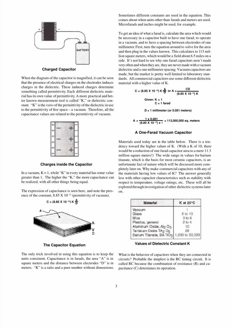
When the diagram of the capacitor is magnified, it can be seen
that the presence of electrical charges on the electrodes induces
charges in the dielectric. These induced charges determine
something called permittivity. Each different dielectric mate-
rial has its own value of permittivity. A more practical and bet-
ter known measurement tool is called “K,” or dielectric con-
stant. “K” is the ratio of the permittivity of the dielectric in use
to the permittivity of free space – a vacuum. Therefore, all the
capacitance values are related to the permittivity of vacuum.
In a vacuum, K = 1, while “K” in every material has some valuegreater than 1. The higher the “K,” the more capacitance can
be realized, with all other things being equal.
The expression of capacitance is seen here, and note the pres-
ence of the constant, 8.85 X 10⁻¹² (permittivity of vacuum).
The only trick involved in using this equation is to keep the
units consistent. Capacitance is in farads, the area “A” is in
square meters and the distance between electrodes “D” is in
meters. “K” is a ratio and a pure number without dimensions.
Sometimes different constants are used in the equation. This
comes about when units other than farads and meters are used.
Microfarads and inches might be used, for example.
To get an idea of what a farad is, calculate the area which would
be necessary in a capacitor built to have one farad, to operate
in a vacuum, and to have a spacing between electrodes of one
millimeter. First, turn the equation around to solve for the area
and then plug in the values known. This calculates to 113 mil-
lion square meters, which would be a field about 6.5 miles on aside. It’s not hard to see why one farad capacitors aren’t made
very often and when they are, they are never made with a vacuum
dielectric and a one millimeter spacing. Vacuum capacitors are
made, but the market is pretty well limited to laboratory stan-
dards. All commercial capacitors use some different dielectric
material with a higher value of K.
Materials used today are in the table below. There is a ten-
dency toward the higher values of K. (With a K of 10, there
would be a reduction of one farad capacitor area to a mere 11.3
million square meters!) The wide range in values for barium
titanate, which is the basis for most ceramic capacitors, is an
unfortunate fact of nature which will be discussed more com-
pletely later on. Why make commercial capacitors with any of
the materials having low values of K? The answer generallyless with other capacitor characteristics such as stability with
respect to temperature, voltage ratings, etc. These will all be
explored through investigation of other dielectric systems later
on.
What is the behavior of capacitors when they are connected in
circuits? Probable the simplest is the RC timing circuit. It is
called RC because the combination of resistance (R) and ca-
pacitance (C) determines its operation.
3
Charged Capacitor
Charges inside the Capacitor
The Capacitor Equation
C = (8.85 X 10 -12) KAD
C = (8.85 X 10 -12) KAD
or A =(8.85 X 10 -12) K
CD
Given: K = 1C = 1 farad
D = 1 millimeter (or 0.001 meters)
A = = 113,000,000 sq. meters1 x 0.001
(8.85 X 10 -12) x 1
A One-Farad Vacuum Capacitor
Values of Dielectric Constant K
8/6/2019 Sec5 Capacitor
http://slidepdf.com/reader/full/sec5-capacitor 4/12
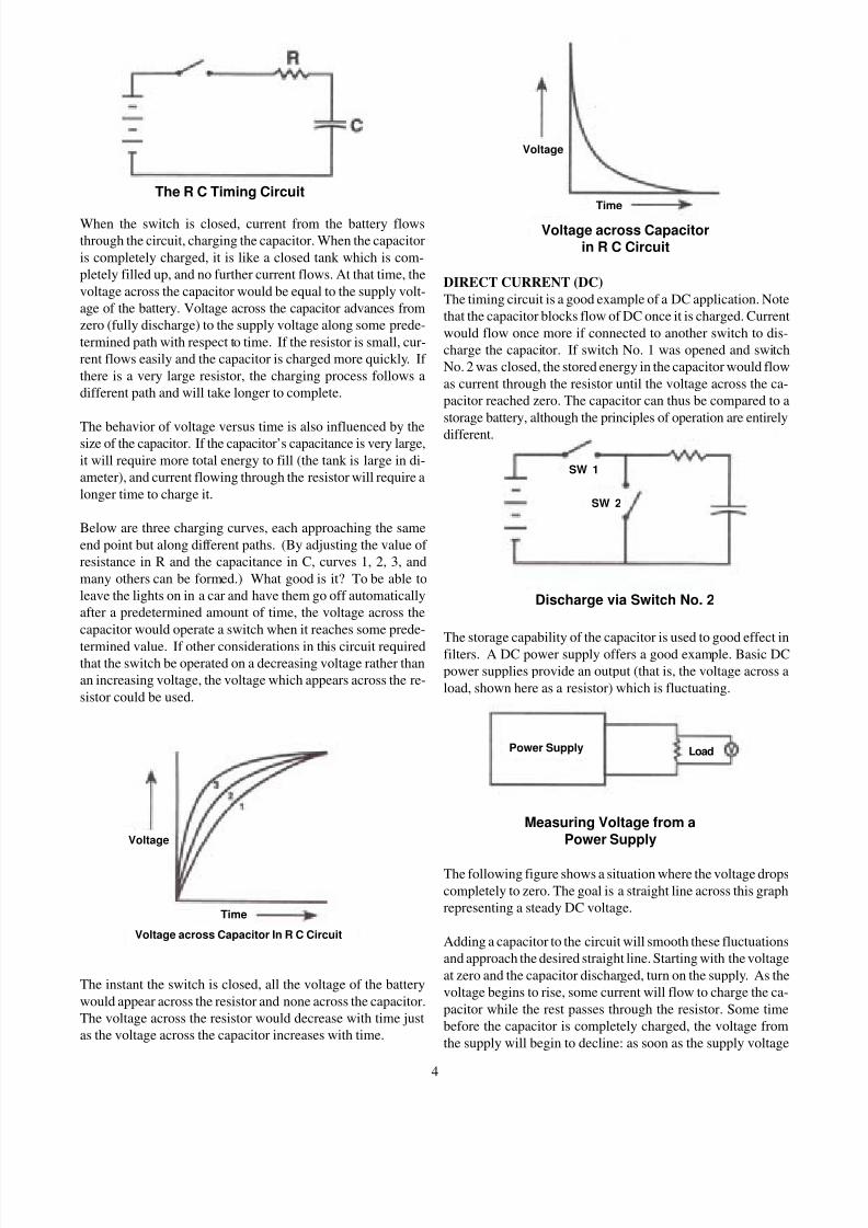
When the switch is closed, current from the battery flows
through the circuit, charging the capacitor. When the capacitor
is completely charged, it is like a closed tank which is com-
pletely filled up, and no further current flows. At that time, the
voltage across the capacitor would be equal to the supply volt-
age of the battery. Voltage across the capacitor advances from
zero (fully discharge) to the supply voltage along some prede-
termined path with respect to time. If the resistor is small, cur-
rent flows easily and the capacitor is charged more quickly. If
there is a very large resistor, the charging process follows a
different path and will take longer to complete.
The behavior of voltage versus time is also influenced by thesize of the capacitor. If the capacitor’s capacitance is very large,
it will require more total energy to fill (the tank is large in di-
ameter), and current flowing through the resistor will require a
longer time to charge it.
Below are three charging curves, each approaching the same
end point but along different paths. (By adjusting the value of
resistance in R and the capacitance in C, curves 1, 2, 3, and
many others can be formed.) What good is it? To be able to
leave the lights on in a car and have them go off automatically
after a predetermined amount of time, the voltage across the
capacitor would operate a switch when it reaches some prede-
termined value. If other considerations in this circuit requiredthat the switch be operated on a decreasing voltage rather than
an increasing voltage, the voltage which appears across the re-
sistor could be used.
The instant the switch is closed, all the voltage of the battery
would appear across the resistor and none across the capacitor.
The voltage across the resistor would decrease with time just
as the voltage across the capacitor increases with time.
DIRECT CURRENT (DC)
The timing circuit is a good example of a DC application. Note
that the capacitor blocks flow of DC once it is charged. Current
would flow once more if connected to another switch to dis-
charge the capacitor. If switch No. 1 was opened and switch
No. 2 was closed, the stored energy in the capacitor would flow
as current through the resistor until the voltage across the ca-
pacitor reached zero. The capacitor can thus be compared to a
storage battery, although the principles of operation are entirely
different.
The storage capability of the capacitor is used to good effect in
filters. A DC power supply offers a good example. Basic DC
power supplies provide an output (that is, the voltage across a
load, shown here as a resistor) which is fluctuating.
The following figure shows a situation where the voltage drops
completely to zero. The goal is a straight line across this graph
representing a steady DC voltage.
Adding a capacitor to the circuit will smooth these fluctuations
and approach the desired straight line. Starting with the voltage
at zero and the capacitor discharged, turn on the supply. As the
voltage begins to rise, some current will flow to charge the ca-
pacitor while the rest passes through the resistor. Some time
before the capacitor is completely charged, the voltage from
the supply will begin to decline: as soon as the supply voltage
4
The R C Timing Circuit
Voltage across Capacitor In R C Circuit
Measuring Voltage from a
Power Supply
Power Supply Load
SW 2
SW 1
Time
Voltage
Voltage
Time
Discharge via Switch No. 2
Voltage across Capacitorin R C Circuit
8/6/2019 Sec5 Capacitor
http://slidepdf.com/reader/full/sec5-capacitor 5/12
is below the capacitor voltage, the capacitor will begin to dis-
charge, and the current will flow from the capacitor, maintain-
ing the voltage across the resistor. If the value of capacitance is
chosen correctly, the capacitor cannot be totally discharged
during the time available, and the capacitor will be charged
once more as the supply voltage exceeds the capacitor voltage.
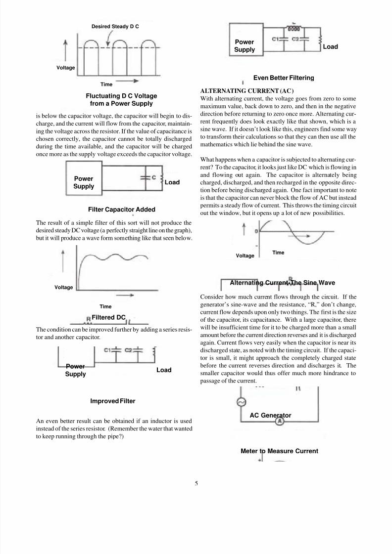
The result of a simple filter of this sort will not produce the
desired steady DC voltage (a perfectly straight line on the graph),
but it will produce a wave form something like that seen below.
The condition can be improved further by adding a series resis-
tor and another capacitor.
An even better result can be obtained if an inductor is used
instead of the series resistor. (Remember the water that wanted
to keep running through the pipe?)
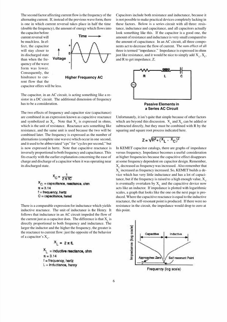
ALTERNATING CURRENT (AC)
With alternating current, the voltage goes from zero to somemaximum value, back down to zero, and then in the negative
direction before returning to zero once more. Alternating cur-
rent frequently does look exactly like that shown, which is a
sine wave. If it doesn’t look like this, engineers find some way
to transform their calculations so that they can then use all the
mathematics which lie behind the sine wave.
What happens when a capacitor is subjected to alternating cur-
rent? To the capacitor, it looks just like DC which is flowing in
and flowing out again. The capacitor is alternately being
charged, discharged, and then recharged in the opposite direc-
tion before being discharged again. One fact important to note
is that the capacitor can never block the flow of AC but instead
permits a steady flow of current. This throws the timing circuit
out the window, but it opens up a lot of new possibilities.
Consider how much current flows through the circuit. If the
generator’s sine-wave and the resistance, “R,” don’t change,
current flow depends upon only two things. The first is the size
of the capacitor, its capacitance. With a large capacitor, there
will be insufficient time for it to be charged more than a small
amount before the current direction reverses and it is discharged
again. Current flows very easily when the capacitor is near its
discharged state, as noted with the timing circuit. If the capaci-
tor is small, it might approach the completely charged state
before the current reverses direction and discharges it. The
smaller capacitor would thus offer much more hindrance to
passage of the current.
5
Time
Voltage
Time
Voltage
TimeVoltage
Fluctuating D C Voltagefrom a Power Supply
Desired Steady D C
Filter Capacitor Added
PowerSupply
Filtered DC
Load
Power
SupplyLoad
Improved Filter
Meter to Measure Current
AC Generator
Alternating Current-The Sine Wave
Even Better Filtering
PowerSupply Load
8/6/2019 Sec5 Capacitor
http://slidepdf.com/reader/full/sec5-capacitor 6/12
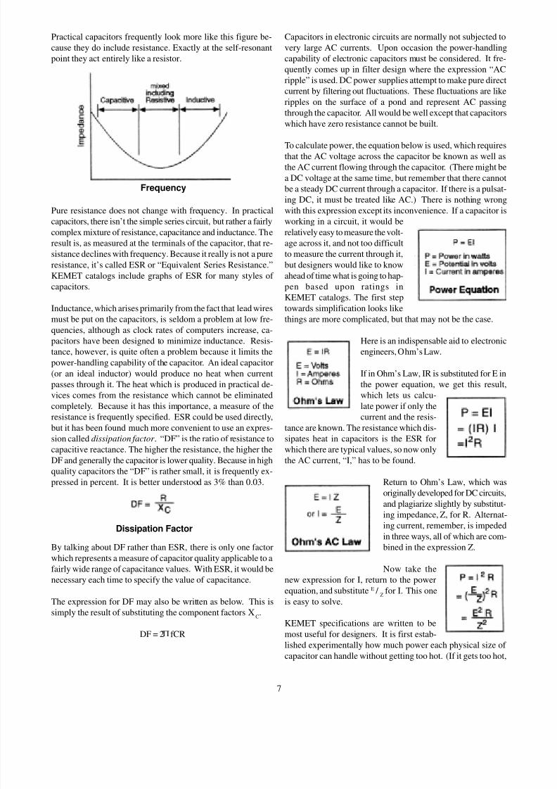
The second factor affecting current flow is the frequency of the
alternating current. If, instead of the previous wave form, there
is one in which current reversal takes place in half the time
(double the frequency), the amount of energy which flows into
the capacitor before
current reversal will
be much less. In ef-
fect, the capacitor
will stay closer to
its discharged statethan when the fre-
quency of the wave
form was lower.
Consequently, the
hindrance to cur-
rent flow that the
capacitor offers will be less.
The capacitor, in an AC circuit, is acting something like a re-
sistor in a DC circuit. The additional dimension of frequency
has to be a consideration.
The two effects of frequency and capacitor size (capacitance)are combined in an expression known as capacitive reactance
and symbolized as XC. Note that X
Cis expressed in ohms,
which is the unit of resistance. Reactance acts something like
resistance, and the same unit is used because the two will be
combined later. The frequency is expressed as the number of
alternations (complete sine waves) which occur in one second,
and it used to be abbreviated “cps” for “cycles per second,” but
is now expressed in hertz. Note that capacitive reactance is
inversely proportional to both frequency and capacitance. This
fits exactly with the earlier explanation concerning the ease of
charge and discharge of a capacitor when it was operating near
its discharged state.
There is a comparable expression for inductance which yields
inductive reactance. The unit of inductance is the Henry. It
follows that inductance in an AC circuit impeded the flow of
the current just as a capacitor does. The difference is that XL
is
directly proportional to both frequency and inductance. The
larger the inductor and the higher the frequency, the greater is
the reactance to current flow: just the opposite of the behavior
of a capacitor’s XC.
Capacitors include both resistance and inductance, because it
is not possible to make practical devices completely lacking in
these factors. Below is a series circuit with all three: resis-
tance, inductance and capacitance, and all capacitors actually
look something like this. If the capacitor is a good one, the
amount of resistance and inductance is very small compared to
the amount of capacitance. In an AC circuit, all three compo-
nents act to decrease the flow of current. The sum effect of all
three is termed “impedance.” Impedance is expressed in ohms
just like resistance, and it would be nice to simply add XL, XC,and R to get impedance, Z.
Unfortunately, it isn’t quite that simple because of other factors
which are beyond this discussion. XL
and XC
can be added or
subtracted directly, but they must be combined with R by the
squaring and square root process indicated here.
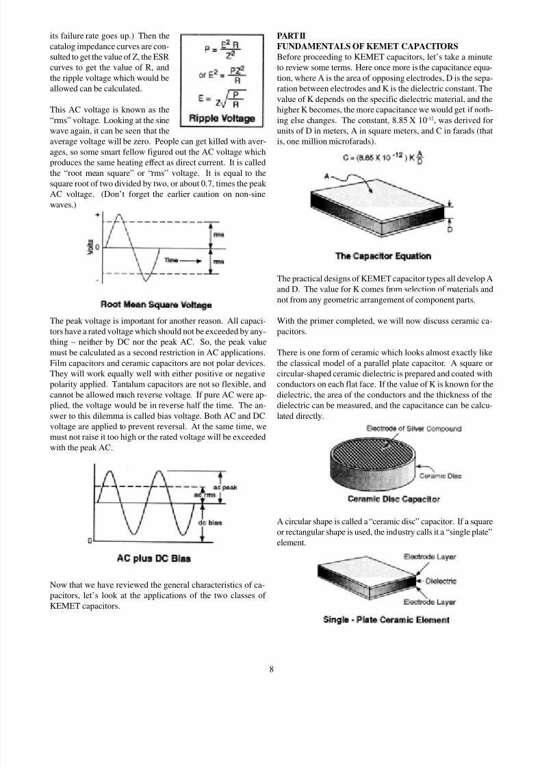
In KEMET capacitor catalogs, there are graphs of impedance
versus frequency. Impedance becomes a useful consideration
at higher frequencies because the capacitive effect disappears
at some frequency dependent on capacitor design. Remember,
XC
decreased as frequency was increased. Also remember that
XL increased as frequency increased. So, KEMET builds a de-vice which has very little inductance and has a lot of capaci-
tance, but if the frequency is raised to a high enough value, XC
is eventually overtaken by XL
and the capacitive device now
acts like an inductor. If impedance is plotted with logarithmic
scales, a graph that looks like the one on the next page is pro-
duced. Where the capacitive reactance is equal to the inductive
reactance, the self-resonant point is produced. If there were no
resistance in the circuit, the impedance would drop to zero at
this point.
6
Time
Voltage
Higher Frequency AC
Passive Elements ina Series AC Circuit
8/6/2019 Sec5 Capacitor
http://slidepdf.com/reader/full/sec5-capacitor 7/12
Capacitors in electronic circuits are normally not subjected to
very large AC currents. Upon occasion the power-handling
capability of electronic capacitors must be considered. It fre-
quently comes up in filter design where the expression “AC
ripple” is used. DC power supplies attempt to make pure direct
current by filtering out fluctuations. These fluctuations are like
ripples on the surface of a pond and represent AC passing
through the capacitor. All would be well except that capacitors
which have zero resistance cannot be built.
To calculate power, the equation below is used, which requires
that the AC voltage across the capacitor be known as well as
the AC current flowing through the capacitor. (There might be
a DC voltage at the same time, but remember that there cannot
be a steady DC current through a capacitor. If there is a pulsat-
ing DC, it must be treated like AC.) There is nothing wrong
with this expression except its inconvenience. If a capacitor is
working in a circuit, it would be
relatively easy to measure the volt-
age across it, and not too difficult
to measure the current through it,
but designers would like to know
ahead of time what is going to hap-pen based upon ratings in
KEMET catalogs. The first step
towards simplification looks like
things are more complicated, but that may not be the case.
Here is an indispensable aid to electronic
engineers, Ohm’s Law.
If in Ohm’s Law, IR is substituted for E in
the power equation, we get this result,
which lets us calcu-
late power if only the
current and the resis-tance are known. The resistance which dis-
sipates heat in capacitors is the ESR for
which there are typical values, so now only
the AC current, “I,” has to be found.
Return to Ohm’s Law, which was
originally developed for DC circuits,
and plagiarize slightly by substitut-
ing impedance, Z, for R. Alternat-
ing current, remember, is impeded
in three ways, all of which are com-
bined in the expression Z.
Now take the
new expression for I, return to the power
equation, and substitute E / Z
for I. This one
is easy to solve.
KEMET specifications are written to be
most useful for designers. It is first estab-
lished experimentally how much power each physical size of
capacitor can handle without getting too hot. (If it gets too hot,
7
Practical capacitors frequently look more like this figure be-
cause they do include resistance. Exactly at the self-resonant
point they act entirely like a resistor.
Pure resistance does not change with frequency. In practical
capacitors, there isn’t the simple series circuit, but rather a fairly
complex mixture of resistance, capacitance and inductance. The
result is, as measured at the terminals of the capacitor, that re-
sistance declines with frequency. Because it really is not a pure
resistance, it’s called ESR or “Equivalent Series Resistance.”
KEMET catalogs include graphs of ESR for many styles of capacitors.
Inductance, which arises primarily from the fact that lead wires
must be put on the capacitors, is seldom a problem at low fre-
quencies, although as clock rates of computers increase, ca-
pacitors have been designed to minimize inductance. Resis-
tance, however, is quite often a problem because it limits the
power-handling capability of the capacitor. An ideal capacitor
(or an ideal inductor) would produce no heat when current
passes through it. The heat which is produced in practical de-
vices comes from the resistance which cannot be eliminated
completely. Because it has this importance, a measure of the
resistance is frequently specified. ESR could be used directly,but it has been found much more convenient to use an expres-
sion called dissipation factor . “DF” is the ratio of resistance to
capacitive reactance. The higher the resistance, the higher the
DF and generally the capacitor is lower quality. Because in high
quality capacitors the “DF” is rather small, it is frequently ex-
pressed in percent. It is better understood as 3% than 0.03.
By talking about DF rather than ESR, there is only one factor
which represents a measure of capacitor quality applicable to a
fairly wide range of capacitance values. With ESR, it would be
necessary each time to specify the value of capacitance.
The expression for DF may also be written as below. This is
simply the result of substituting the component factors XC.
DF = 2 fCR
Frequency
Dissipation Factor
8/6/2019 Sec5 Capacitor
http://slidepdf.com/reader/full/sec5-capacitor 8/12
its failure rate goes up.) Then the
catalog impedance curves are con-
sulted to get the value of Z, the ESR
curves to get the value of R, and
the ripple voltage which would be
allowed can be calculated.
This AC voltage is known as the
“rms” voltage. Looking at the sine
wave again, it can be seen that theaverage voltage will be zero. People can get killed with aver-
ages, so some smart fellow figured out the AC voltage which
produces the same heating effect as direct current. It is called
the “root mean square” or “rms” voltage. It is equal to the
square root of two divided by two, or about 0.7, times the peak
AC voltage. (Don’t forget the earlier caution on non-sine
waves.)
The peak voltage is important for another reason. All capaci-
tors have a rated voltage which should not be exceeded by any-
thing – neither by DC nor the peak AC. So, the peak value
must be calculated as a second restriction in AC applications.
Film capacitors and ceramic capacitors are not polar devices.
They will work equally well with either positive or negative
polarity applied. Tantalum capacitors are not so flexible, and
cannot be allowed much reverse voltage. If pure AC were ap-
plied, the voltage would be in reverse half the time. The an-swer to this dilemma is called bias voltage. Both AC and DC
voltage are applied to prevent reversal. At the same time, we
must not raise it too high or the rated voltage will be exceeded
with the peak AC.
Now that we have reviewed the general characteristics of ca-
pacitors, let’s look at the applications of the two classes of
KEMET capacitors.
PART II
FUNDAMENTALS OF KEMET CAPACITORS
Before proceeding to KEMET capacitors, let’s take a minute
to review some terms. Here once more is the capacitance equa-
tion, where A is the area of opposing electrodes, D is the sepa-
ration between electrodes and K is the dielectric constant. The
value of K depends on the specific dielectric material, and the
higher K becomes, the more capacitance we would get if noth-
ing else changes. The constant, 8.85 X 10⁻¹², was derived for
units of D in meters, A in square meters, and C in farads (thatis, one million microfarads).
The practical designs of KEMET capacitor types all develop A
and D. The value for K comes from selection of materials and
not from any geometric arrangement of component parts.
With the primer completed, we will now discuss ceramic ca-
pacitors.
There is one form of ceramic which looks almost exactly like
the classical model of a parallel plate capacitor. A square or
circular-shaped ceramic dielectric is prepared and coated with
conductors on each flat face. If the value of K is known for the
dielectric, the area of the conductors and the thickness of the
dielectric can be measured, and the capacitance can be calcu-lated directly.
A circular shape is called a “ceramic disc” capacitor. If a square
or rectangular shape is used, the industry calls it a “single plate”
element.
8
8/6/2019 Sec5 Capacitor
http://slidepdf.com/reader/full/sec5-capacitor 9/12
In commercial practice, the dielectric is made from finely pow-
dered materials, the chief of which is barium titanate. Disc ele-
ments are pressed in dies and then fired at high temperature to
produce a very dense structure. Single-plate elements are usu-
ally cut from larger sheets of fired ceramic material. Electrodes
for both discs and single-plates are formed from a compound
containing powdered silver, powdered glass, and an organic
binder. This material is screen-printed onto the discs or sheets
from which the single plates will be cut. Another firing step
removes the binder and melts the glass, binding the silver glassmatrix to the ceramic surfaces.
The outer surface is easily solderable, and wires are usually
attached as seen here in a radial configuration. The hairpin-
shaped wires are springy enough to hold the ceramic elements
while the assembly is dipped in solder. The lower end of the
hairpin is cut off later. This process can be mechanized readily,
and dipped discs are among the cheapest capacitors available.
Unless some special means is taken to remove the electrode
compound from the periphery of the single plate element, there
is a hazard of conductors bridging across the dielectric to short-
circuit the capacitor. Single plates could be printed like discs,
but the feeding and locating problems increase cost and reduceaccuracy of capacitance achieved.
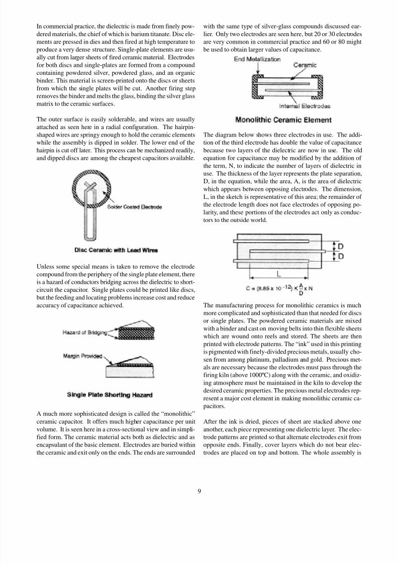
A much more sophisticated design is called the “monolithic”
ceramic capacitor. It offers much higher capacitance per unit
volume. It is seen here in a cross-sectional view and in simpli-
fied form. The ceramic material acts both as dielectric and as
encapsulant of the basic element. Electrodes are buried within
the ceramic and exit only on the ends. The ends are surrounded
with the same type of silver-glass compounds discussed ear-
lier. Only two electrodes are seen here, but 20 or 30 electrodes
are very common in commercial practice and 60 or 80 might
be used to obtain larger values of capacitance.
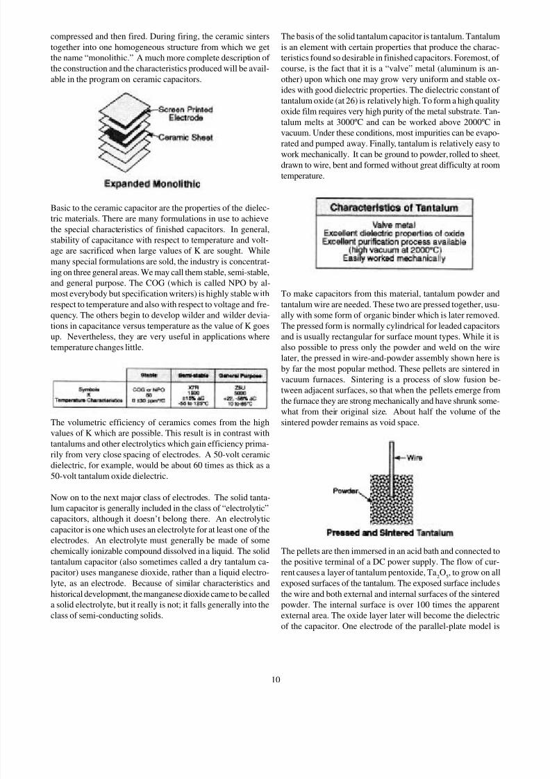
The diagram below shows three electrodes in use. The addi-
tion of the third electrode has double the value of capacitance
because two layers of the dielectric are now in use. The old
equation for capacitance may be modified by the addition of
the term, N, to indicate the number of layers of dielectric in
use. The thickness of the layer represents the plate separation,
D, in the equation, while the area, A, is the area of dielectric
which appears between opposing electrodes. The dimension,
L, in the sketch is representative of this area; the remainder of the electrode length does not face electrodes of opposing po-
larity, and these portions of the electrodes act only as conduc-
tors to the outside world.
The manufacturing process for monolithic ceramics is much
more complicated and sophisticated than that needed for discs
or single plates. The powdered ceramic materials are mixed
with a binder and cast on moving belts into thin flexible sheets
which are wound onto reels and stored. The sheets are then
printed with electrode patterns. The “ink” used in this printing
is pigmented with finely-divided precious metals, usually cho-
sen from among platinum, palladium and gold. Precious met-
als are necessary because the electrodes must pass through the
firing kiln (above 1000ºC) along with the ceramic, and oxidiz-
ing atmosphere must be maintained in the kiln to develop the
desired ceramic properties. The precious metal electrodes rep-
resent a major cost element in making monolithic ceramic ca-
pacitors.
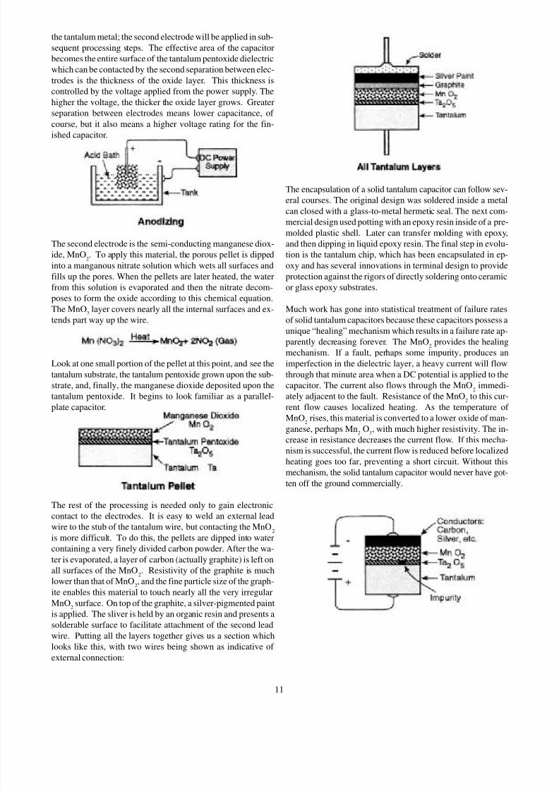
After the ink is dried, pieces of sheet are stacked above one
another, each piece representing one dielectric layer. The elec-
trode patterns are printed so that alternate electrodes exit from
opposite ends. Finally, cover layers which do not bear elec-
trodes are placed on top and bottom. The whole assembly is
9
8/6/2019 Sec5 Capacitor
http://slidepdf.com/reader/full/sec5-capacitor 10/12
compressed and then fired. During firing, the ceramic sinters
together into one homogeneous structure from which we get
the name “monolithic.” A much more complete description of
the construction and the characteristics produced will be avail-
able in the program on ceramic capacitors.
Basic to the ceramic capacitor are the properties of the dielec-
tric materials. There are many formulations in use to achieve
the special characteristics of finished capacitors. In general,
stability of capacitance with respect to temperature and volt-
age are sacrificed when large values of K are sought. While
many special formulations are sold, the industry is concentrat-
ing on three general areas. We may call them stable, semi-stable,and general purpose. The COG (which is called NPO by al-
most everybody but specification writers) is highly stable with
respect to temperature and also with respect to voltage and fre-
quency. The others begin to develop wilder and wilder devia-
tions in capacitance versus temperature as the value of K goes
up. Nevertheless, they are very useful in applications where
temperature changes little.
The volumetric efficiency of ceramics comes from the high
values of K which are possible. This result is in contrast with
tantalums and other electrolytics which gain efficiency prima-
rily from very close spacing of electrodes. A 50-volt ceramic
dielectric, for example, would be about 60 times as thick as a
50-volt tantalum oxide dielectric.
Now on to the next major class of electrodes. The solid tanta-
lum capacitor is generally included in the class of “electrolytic”
capacitors, although it doesn’t belong there. An electrolytic
capacitor is one which uses an electrolyte for at least one of the
electrodes. An electrolyte must generally be made of some
chemically ionizable compound dissolved in a liquid. The solid
tantalum capacitor (also sometimes called a dry tantalum ca-
pacitor) uses manganese dioxide, rather than a liquid electro-
lyte, as an electrode. Because of similar characteristics and
historical development, the manganese dioxide came to be called
a solid electrolyte, but it really is not; it falls generally into the
class of semi-conducting solids.
The basis of the solid tantalum capacitor is tantalum. Tantalum
is an element with certain properties that produce the charac-
teristics found so desirable in finished capacitors. Foremost, of
course, is the fact that it is a “valve” metal (aluminum is an-
other) upon which one may grow very uniform and stable ox-
ides with good dielectric properties. The dielectric constant of
tantalum oxide (at 26) is relatively high. To form a high quality
oxide film requires very high purity of the metal substrate. Tan-
talum melts at 3000ºC and can be worked above 2000ºC in
vacuum. Under these conditions, most impurities can be evapo-rated and pumped away. Finally, tantalum is relatively easy to
work mechanically. It can be ground to powder, rolled to sheet,
drawn to wire, bent and formed without great difficulty at room
temperature.
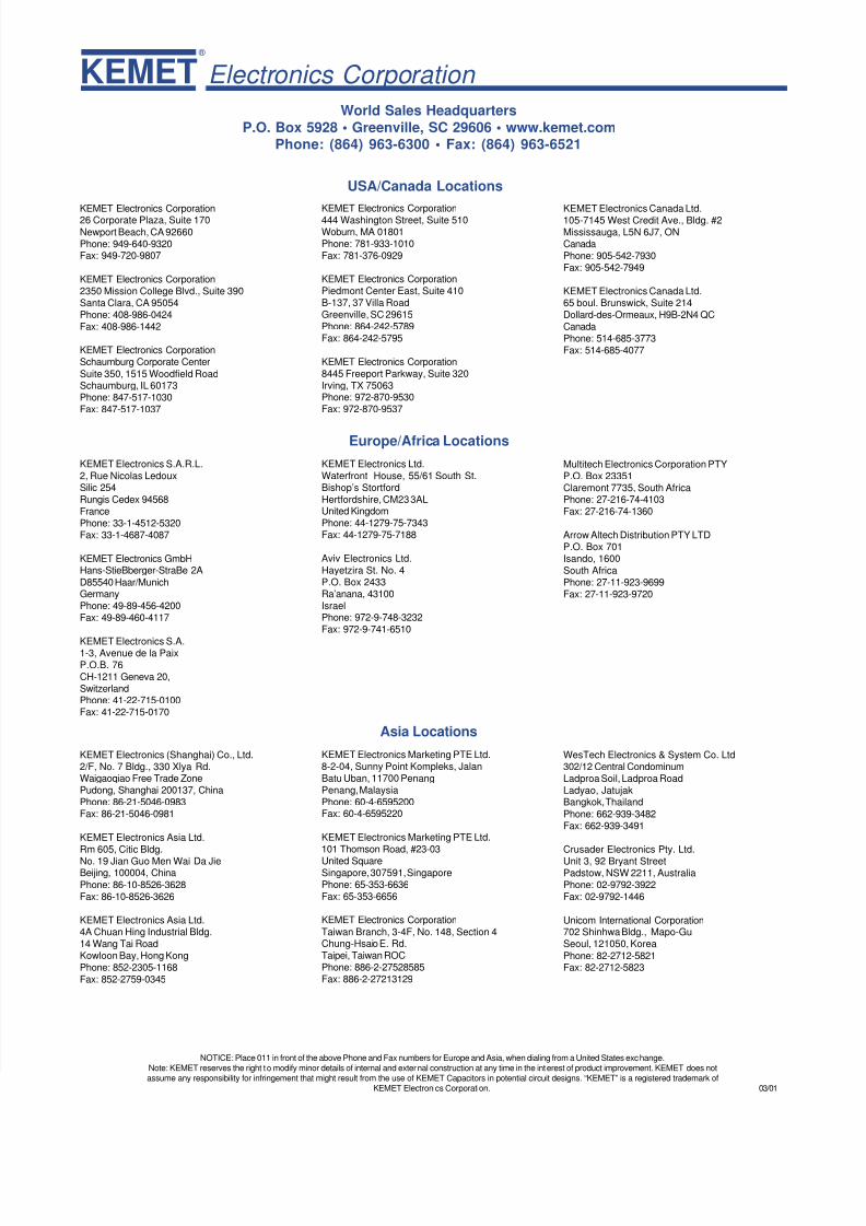
To make capacitors from this material, tantalum powder and
tantalum wire are needed. These two are pressed together, usu-
ally with some form of organic binder which is later removed.
The pressed form is normally cylindrical for leaded capacitors
and is usually rectangular for surface mount types. While it is
also possible to press only the powder and weld on the wire
later, the pressed in wire-and-powder assembly shown here is
by far the most popular method. These pellets are sintered in
vacuum furnaces. Sintering is a process of slow fusion be-
tween adjacent surfaces, so that when the pellets emerge from
the furnace they are strong mechanically and have shrunk some-
what from their original size. About half the volume of thesintered powder remains as void space.
The pellets are then immersed in an acid bath and connected to
the positive terminal of a DC power supply. The flow of cur-
rent causes a layer of tantalum pentoxide, Ta2O
5, to grow on all
exposed surfaces of the tantalum. The exposed surface includes
the wire and both external and internal surfaces of the sintered
powder. The internal surface is over 100 times the apparent
external area. The oxide layer later will become the dielectric
of the capacitor. One electrode of the parallel-plate model is
10
8/6/2019 Sec5 Capacitor
http://slidepdf.com/reader/full/sec5-capacitor 11/12
the tantalum metal; the second electrode will be applied in sub-
sequent processing steps. The effective area of the capacitor
becomes the entire surface of the tantalum pentoxide dielectric
which can be contacted by the second separation between elec-
trodes is the thickness of the oxide layer. This thickness is
controlled by the voltage applied from the power supply. The
higher the voltage, the thicker the oxide layer grows. Greater
separation between electrodes means lower capacitance, of
course, but it also means a higher voltage rating for the fin-
ished capacitor.
The second electrode is the semi-conducting manganese diox-
ide, MnO2. To apply this material, the porous pellet is dipped
into a manganous nitrate solution which wets all surfaces and
fills up the pores. When the pellets are later heated, the waterfrom this solution is evaporated and then the nitrate decom-
poses to form the oxide according to this chemical equation.
The MnO2
layer covers nearly all the internal surfaces and ex-
tends part way up the wire.
Look at one small portion of the pellet at this point, and see the
tantalum substrate, the tantalum pentoxide grown upon the sub-
strate, and, finally, the manganese dioxide deposited upon the
tantalum pentoxide. It begins to look familiar as a parallel-
plate capacitor.
The rest of the processing is needed only to gain electronic
contact to the electrodes. It is easy to weld an external lead
wire to the stub of the tantalum wire, but contacting the MnO2
is more difficult. To do this, the pellets are dipped into water
containing a very finely divided carbon powder. After the wa-
ter is evaporated, a layer of carbon (actually graphite) is left on
all surfaces of the MnO2. Resistivity of the graphite is much
lower than that of MnO2, and the fine particle size of the graph-
ite enables this material to touch nearly all the very irregular
MnO2surface. On top of the graphite, a silver-pigmented paint
is applied. The sliver is held by an organic resin and presents a
solderable surface to facilitate attachment of the second lead
wire. Putting all the layers together gives us a section which
looks like this, with two wires being shown as indicative of
external connection:
The encapsulation of a solid tantalum capacitor can follow sev-
eral courses. The original design was soldered inside a metal
can closed with a glass-to-metal hermetic seal. The next com-
mercial design used potting with an epoxy resin inside of a pre-
molded plastic shell. Later can transfer molding with epoxy,
and then dipping in liquid epoxy resin. The final step in evolu-
tion is the tantalum chip, which has been encapsulated in ep-
oxy and has several innovations in terminal design to provide
protection against the rigors of directly soldering onto ceramicor glass epoxy substrates.
Much work has gone into statistical treatment of failure rates
of solid tantalum capacitors because these capacitors possess a
unique “healing” mechanism which results in a failure rate ap-
parently decreasing forever. The MnO2
provides the healing
mechanism. If a fault, perhaps some impurity, produces an
imperfection in the dielectric layer, a heavy current will flow
through that minute area when a DC potential is applied to the
capacitor. The current also flows through the MnO2
immedi-
ately adjacent to the fault. Resistance of the MnO2
to this cur-
rent flow causes localized heating. As the temperature of
MnO2 rises, this material is converted to a lower oxide of man-ganese, perhaps Mn
2O
3, with much higher resistivity. The in-
crease in resistance decreases the current flow. If this mecha-
nism is successful, the current flow is reduced before localized
heating goes too far, preventing a short circuit. Without this
mechanism, the solid tantalum capacitor would never have got-
ten off the ground commercially.
11
8/6/2019 Sec5 Capacitor
http://slidepdf.com/reader/full/sec5-capacitor 12/12
KEMET Electronics Corporation ®
World Sales Headquarters
P.O. Box 5928 • Greenville, SC 29606 • www.kemet.comPhone: (864) 963-6300 • Fax: (864) 963-6521
KEMET Electronics Corporation26 Corporate Plaza, Suite 170
Newport Beach, CA 92660Phone: 949-640-9320Fax: 949-720-9807
KEMET Electronics Corporation2350 Mission College Blvd., Suite 390Santa Clara, CA 95054Phone: 408-986-0424Fax: 408-986-1442
KEMET Electronics CorporationSchaumburg Corporate Center
Suite 350, 1515 Woodfield RoadSchaumburg, IL 60173Phone: 847-517-1030Fax: 847-517-1037
KEMET Electronics Corporation444 Washington Street, Suite 510Woburn, MA 01801Phone: 781-933-1010Fax: 781-376-0929
KEMET Electronics CorporationPiedmont Center East, Suite 410B-137, 37 Villa RoadGreenville, SC 29615Phone: 864-242-5789Fax: 864-242-5795
KEMET Electronics Corporation8445 Freeport Parkway, Suite 320Irving, TX 75063Phone: 972-870-9530Fax: 972-870-9537
KEMET Electronics Canada Ltd.105-7145 West Credit Ave., Bldg. #2Mississauga, L5N 6J7, ONCanadaPhone: 905-542-7930Fax: 905-542-7949
KEMET Electronics Canada Ltd.65 boul. Brunswick, Suite 214Dollard-des-Ormeaux, H9B-2N4 QCCanadaPhone: 514-685-3773Fax: 514-685-4077
USA/Canada Locations
KEMET Electronics S.A.R.L.2, Rue Nicolas LedouxSilic 254Rungis Cedex 94568FrancePhone: 33-1-4512-5320Fax: 33-1-4687-4087
KEMET Electronics GmbHHans-StieBberger-StraBe 2A
D85540 Haar/MunichGermanyPhone: 49-89-456-4200Fax: 49-89-460-4117
KEMET Electronics S.A.1-3, Avenue de la PaixP.O.B. 76CH-1211 Geneva 20,SwitzerlandPhone: 41-22-715-0100Fax: 41-22-715-0170
KEMET Electronics Ltd.Waterfront House, 55/61 South St.Bishop’s StortfordHertfordshire, CM23 3ALUnited KingdomPhone: 44-1279-75-7343Fax: 44-1279-75-7188
Aviv Electronics Ltd.Hayetzira St. No. 4P.O. Box 2433Ra’anana, 43100IsraelPhone: 972-9-748-3232Fax: 972-9-741-6510
Multitech Electronics Corporation PTYP.O. Box 23351Claremont 7735, South AfricaPhone: 27-216-74-4103Fax: 27-216-74-1360
Arrow Altech Distribution PTY LTDP.O. Box 701Isando, 1600South AfricaPhone: 27-11-923-9699Fax: 27-11-923-9720
Europe/Africa Locations
KEMET Electronics (Shanghai) Co., Ltd.2/F, No. 7 Bldg., 330 Xlya Rd.Waigaoqiao Free Trade ZonePudong, Shanghai 200137, ChinaPhone: 86-21-5046-0983Fax: 86-21-5046-0981
KEMET Electronics Asia Ltd.Rm 605, Citic Bldg.
No. 19 Jian Guo Men Wai Da JieBeijing, 100004, China
Phone: 86-10-8526-3628Fax: 86-10-8526-3626
KEMET Electronics Asia Ltd.4A Chuan Hing Industrial Bldg.14 Wang Tai RoadKowloon Bay, Hong KongPhone: 852-2305-1168Fax: 852-2759-0345
KEMET Electronics Marketing PTE Ltd.8-2-04, Sunny Point Kompleks, JalanBatu Uban, 11700 PenangPenang, MalaysiaPhone: 60-4-6595200Fax: 60-4-6595220
KEMET Electronics Marketing PTE Ltd.101 Thomson Road, #23-03
United SquareSingapore, 307591, SingaporePhone: 65-353-6636Fax: 65-353-6656
KEMET Electronics Corporation
Taiwan Branch, 3-4F, No. 148, Section 4Chung-Hsaio E. Rd.Taipei, Taiwan ROCPhone: 886-2-27528585Fax: 886-2-27213129
WesTech Electronics & System Co. Ltd302/12 Central CondominumLadproa Soil, Ladproa RoadLadyao, JatujakBangkok, Thailand
Phone: 662-939-3482Fax: 662-939-3491
Crusader Electronics Pty. Ltd.
Unit 3, 92 Bryant StreetPadstow, NSW 2211, AustraliaPhone: 02-9792-3922Fax: 02-9792-1446
Unicom International Corporation702 Shinhwa Bldg., Mapo-GuSeoul, 121050, Korea
Phone: 82-2712-5821Fax: 82-2712-5823
Asia Locations
NOTICE: Place 011 in front of the above Phone and Fax numbers for Europe and Asia, when dialing from a United States exchange.Note: KEMET reserves the right to modify minor details of internal and external construction at any time in the interest of product improvement. KEMET does not
ibilit f i f i t th t i ht lt f th f KEMET C it i t ti l i it d i “KEMET” i i t d t d k f
Related Documents