AIR CONDITIONERS CITY MULTI Models PUHY-400YMF-C, 500YMF-C PUHY-P400YMF-C, P500YMF-C PUHY-600YSMF-C, 650YSMF-C, 700YSMF-C, 750YSMF-C PUHY-P600YSMF-C, P650YSMF-C, P700YSMF-C, P750YSMF-C Service Handbook Service Handbook PUHY-400YMF-C, 500YMF-C PUHY-P400YMF-C, P500YMF-C PUHY-600YSMF-C, 650YSMF-C, 700YSMF-C, 750YSMF-C PUHY-P600YSMF-C, P650YSMF-C, P700YSMF-C, P750YSMF-C HEAD OFFICE MITSUBISHI DENKI BLDG.MARUNOUCHI TOKYO 100-0005 TELEX J24532 CABLE MELCO TOKYO Issued in May 2003 MEE02K140 Printed in Japan New publication effective Jan 2003 Specifications subject to change without notice. Service Handbook PUHY-400·500YMF-C/PUHY-P400·P500YMF-C/PUHY-600·650·700·750YSMF-C/PUHY-P600·P650·P700·P750YSMF-C

Welcome message from author
This document is posted to help you gain knowledge. Please leave a comment to let me know what you think about it! Share it to your friends and learn new things together.
Transcript
AIR CONDITIONERS CITY MULTI
Models PUHY-400YMF-C, 500YMF-CPUHY-P400YMF-C, P500YMF-CPUHY-600YSMF-C, 650YSMF-C, 700YSMF-C, 750YSMF-CPUHY-P600YSMF-C, P650YSMF-C, P700YSMF-C, P750YSMF-C
Service Handbook
Service Handbook PUHY-400YMF-C, 500YMF-CPUHY-P400YMF-C, P500YMF-CPUHY-600YSMF-C, 650YSMF-C, 700YSMF-C, 750YSMF-CPUHY-P600YSMF-C, P650YSMF-C, P700YSMF-C, P750YSMF-C
HEAD OFFICE MITSUBISHI DENKI BLDG. MARUNOUCHI TOKYO 100-0005 TELEX J24532 CABLE MELCO TOKYO
Issued in May 2003 MEE02K140 Printed in Japan
New publication effective Jan 2003Specifications subject to change without notice.
Service H
andbook PU
HY-400·500Y
MF
-C/P
UH
Y-P400·P
500YM
F-C
/PU
HY-600·650·700·750Y
SM
F-C
/PU
HY-P
600·P650·P
700·P750Y
SM
F-C
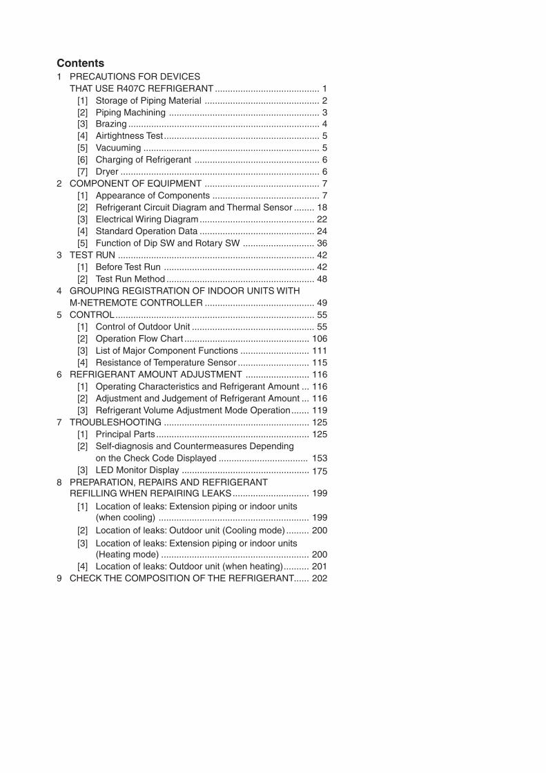
Contents1 PRECAUTIONS FOR DEVICES
THAT USE R407C REFRIGERANT ......................................... 1[1] Storage of Piping Material ............................................. 2[2] Piping Machining ........................................................... 3[3] Brazing ........................................................................... 4[4] Airtightness Test ............................................................. 5[5] Vacuuming ..................................................................... 5[6] Charging of Refrigerant ................................................. 6[7] Dryer .............................................................................. 6
2 COMPONENT OF EQUIPMENT ............................................. 7[1] Appearance of Components .......................................... 7[2] Refrigerant Circuit Diagram and Thermal Sensor ........ 18[3] Electrical Wiring Diagram............................................. 22[4] Standard Operation Data ............................................. 24[5] Function of Dip SW and Rotary SW ............................ 36
3 TEST RUN ............................................................................. 42[1] Before Test Run ........................................................... 42[2] Test Run Method .......................................................... 48
4 GROUPING REGISTRATION OF INDOOR UNITS WITHM-NETREMOTE CONTROLLER ........................................... 49
5 CONTROL.............................................................................. 55[1] Control of Outdoor Unit ................................................ 55[2] Operation Flow Chart ................................................. 106[3] List of Major Component Functions ........................... 111[4] Resistance of Temperature Sensor ............................ 115
6 REFRIGERANT AMOUNT ADJUSTMENT ......................... 116[1] Operating Characteristics and Refrigerant Amount ... 116[2] Adjustment and Judgement of Refrigerant Amount ... 116[3] Refrigerant Volume Adjustment Mode Operation....... 119
7 TROUBLESHOOTING ......................................................... 125[1] Principal Parts ............................................................ 125[2] Self-diagnosis and Countermeasures Depending
on the Check Code Displayed ................................... 153175[3] LED Monitor Display ..................................................
8.............................. 199
[1]........................................................... 199
[2] ......... 200[3]
.......................................................... 200[4] .......... 201
9 ...... 202
PREPARATION, REPAIRS AND REFRIGERANT REFILLING WHEN REPAIRING LEAKS
Location of leaks: Extension piping or indoor units (when cooling)Location of leaks: Outdoor unit (Cooling mode)Location of leaks: Extension piping or indoor units (Heating mode)Location of leaks: Outdoor unit (when heating)
CHECK THE COMPOSITION OF THE REFRIGERANT
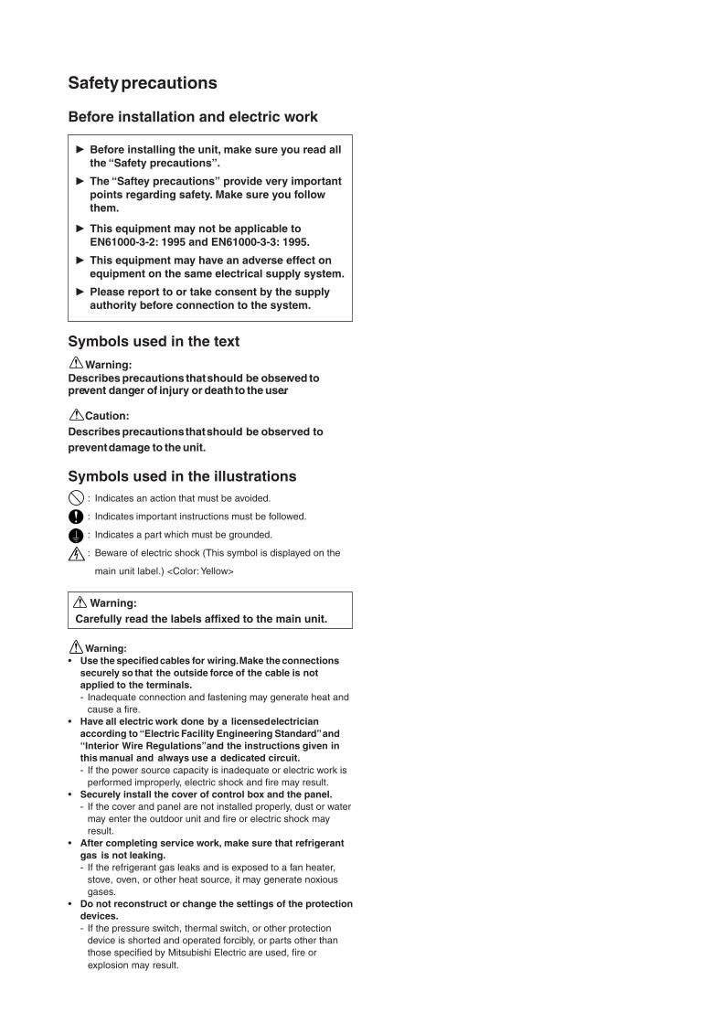
Safety precautions
This equipment may not be applicable to EN61000-3-2: 1995 and EN61000-3-3: 1995.
Please report to or take consent by the supply authority before connection to the system.
Symbols used in the text
Warning:Describes precautions that should be observed toprevent danger of injury or death to the user.
Caution:Describes precautions that should be observed toprevent damage to the unit.
Symbols used in the illustrations: Indicates an action that must be avoided.
: Indicates important instructions must be followed.
: Indicates a part which must be grounded.
: Beware of electric shock (This symbol is displayed on the
main unit label.) <Color: Yellow>
Warning:Carefully read the labels affixed to the main unit.
Warning:• Use the specified cables for wiring. Make the connections
securely so that the outside force of the cable is notapplied to the terminals.- Inadequate connection and fastening may generate heat and
cause a fire.• Have all electric work done by a licensed electrician
according to “Electric Facility Engineering Standard” and“Interior Wire Regulations”and the instructions given inthis manual and always use a dedicated circuit.- If the power source capacity is inadequate or electric work is
performed improperly, electric shock and fire may result.• Securely install the cover of control box and the panel.
- If the cover and panel are not installed properly, dust or watermay enter the outdoor unit and fire or electric shock mayresult.
• After completing service work, make sure that refrigerantgas is not leaking.- If the refrigerant gas leaks and is exposed to a fan heater,
stove, oven, or other heat source, it may generate noxiousgases.
• Do not reconstruct or change the settings of the protectiondevices.- If the pressure switch, thermal switch, or other protection
device is shorted and operated forcibly, or parts other thanthose specified by Mitsubishi Electric are used, fire orexplosion may result.
Before installing the unit, make sure you read allthe “Safety precautions”.
The “Saftey precautions” provide very important points regarding safety. Make sure you followthem.
This equipment may have an adverse effect onequipment on the same electrical supply system.
Before installation and electric work
-1-
¡ PRECAUTIONS FOR DEVICES THAT USE R407C REFRIGERANT
Caution
Do not use the existing refrigerant piping.
• The old refrigerant and refrigerator oil in the existingpiping contains a large amount of chlorine which maycause the refrigerator oil of the new unit to deterio-rate.
Use refrigerant piping made of phosphorus deoxi-dized copper and copper alloy seamless pipes andtubes”. In addition, be sure that the inner and outersurfaces of the pipes are clean and free of hazardoussulphur, oxides, dust/dirt, shaving particles, oils,moisture, or any other contaminant.
• Contaminants on the inside of the refrigerant pipingmay cause the refrigerant residual oil to deteriorate.
Store the piping to be used during installation indoorsand keep both ends of the piping sealed until justbefore brazing. (Store elbows and other joints in aplastic bag.)
• If dust, dirt, or water enters the refrigerant cycle,deterioration of the oil and compressor trouble mayresult.
Use ester oil, ether oil or alkylbenzene (smallamount) as the refrigerator oil to coat flares andflange connections.
• The refrigerator oil will degrade if it is mixed with a
large amount of mineral oil.
Use liquid refrigerant to seal the system.
• If gas refrigerant is used to seal the system, the com-position of the refrigerant in the cylinder will changeand performance may drop.
Do not use a refrigerant other than that specified.
• If another refrigerant is used, the chlorine in the refrigerant may cause the refrigerator oil to
Use a vacuum pump with a reverse flow check valve.
• The vacuum pump oil may flow back into the refriger-ant cycle and cause the refrigerator oil to deteriorate.
Do not use the following tools that have been usedwith conventional refrigerants.(Gauge manifold, charge hose, gas leak detector, re-verse flow check valve, refrigerant charge base,vacuum gauge, refrigerant recovery equipment)
• If the conventional refrigerant and refrigerator oil aremixed in the R407C, the refrigerant may deterio-rated.
• If water is mixed in the R407C, the refrigerator oilmay deteriorate.
• Since R407C does not contain any chlorine, gasleak detectors for conventional refrigerants will notreact to it.
Do not use a charging cylinder.
• Using a charging cylinder may cause the refrigerantto deteriorate.
Be especially careful when managing tools.
• If dust, dirt, or water that gets in the refrigerant cycle, may cause the refrigerant to deteriorate.
If the refrigerant leaks, recover the refrigerant in therefrigerant cycle, then recharge the cycle with thespecified amount of the liquid refrigerant indicatedon the air conditioner.
• Since R407C is a nonazeotropic refrigerant, if addi-tionally charged when the refrigerant leaked, the com-position of the refrigerant in the refrigerant cycle willchange and result in a drop in performance or abnor-mal stopping.
deteriorate.
-2-
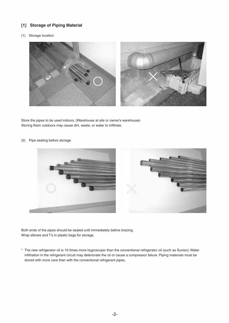
[1] Storage of Piping Material
(1) Storage location
Store the pipes to be used indoors. (Warehouse at site or owner’s warehouse)
Storing them outdoors may cause dirt, waste, or water to infiltrate.
(2) Pipe sealing before storage
Both ends of the pipes should be sealed until immediately before brazing.
Wrap elbows and T’s in plastic bags for storage.
* The new refrigerator oil is 10 times more hygroscopic than the conventional refrigerator oil (such as Suniso). Waterinfiltration in the refrigerant circuit may deteriorate the oil or cause a compressor failure. Piping materials must be
stored with more care than with the conventional refrigerant pipes.
-3-
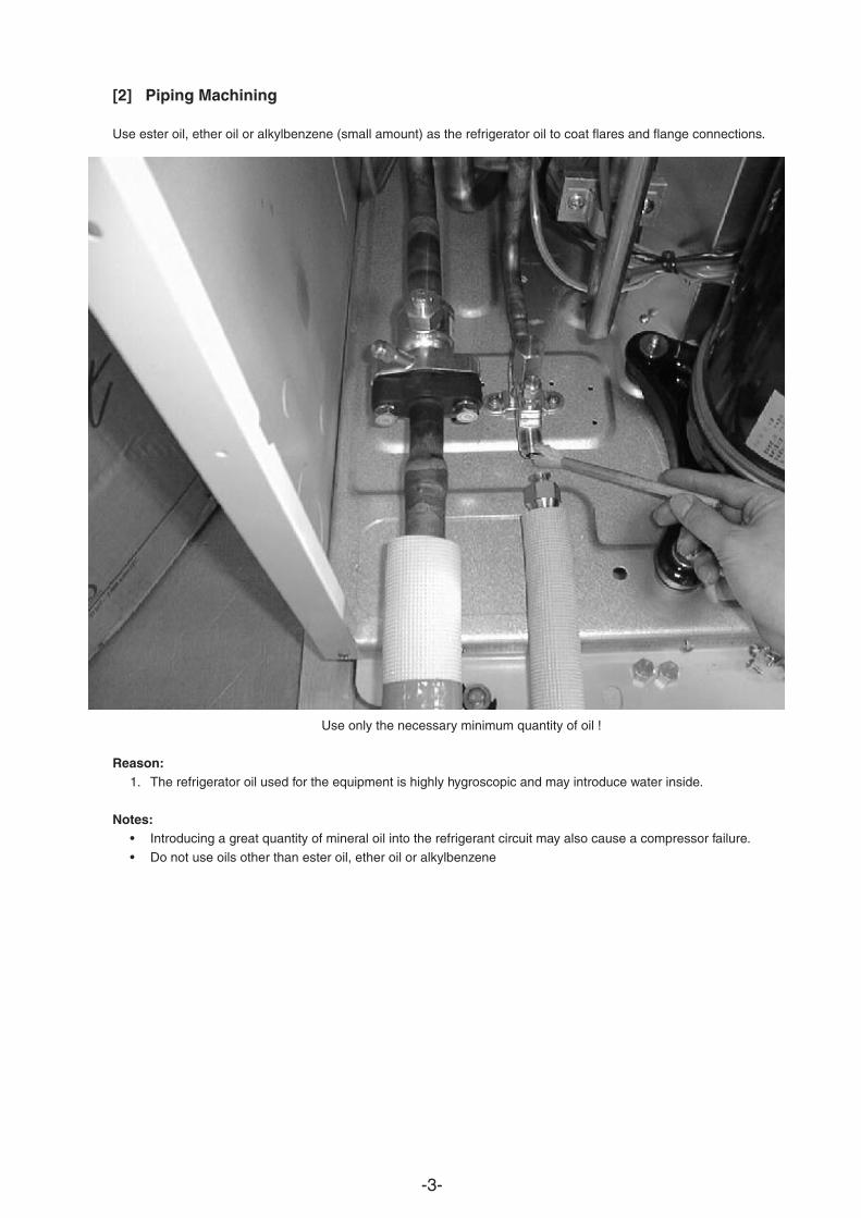
[2] Piping Machining
Use ester oil, ether oil or alkylbenzene (small amount) as the refrigerator oil to coat flares and flange connections.
Use only the necessary minimum quantity of oil !
Reason:1. The refrigerator oil used for the equipment is highly hygroscopic and may introduce water inside.
Notes:• Introducing a great quantity of mineral oil into the refrigerant circuit may also cause a compressor failure.
• Do not use oils other than ester oil, ether oil or alkylbenzene
-4-
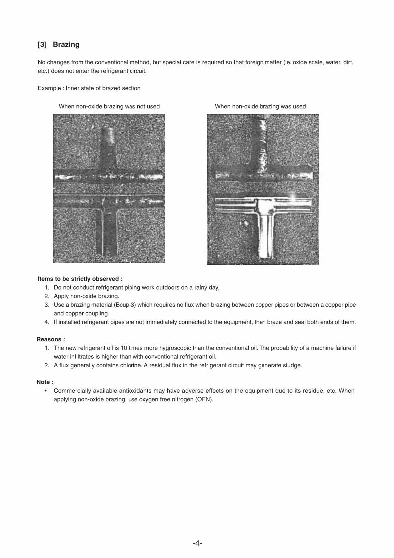
[3] Brazing
No changes from the conventional method, but special care is required so that foreign matter (ie. oxide scale, water, dirt,
etc.) does not enter the refrigerant circuit.
Example : Inner state of brazed section
When non-oxide brazing was not used When non-oxide brazing was used
Items to be strictly observed :1. Do not conduct refrigerant piping work outdoors on a rainy day.2. Apply non-oxide brazing.
3. Use a brazing material (Bcup-3) which requires no flux when brazing between copper pipes or between a copper pipe
and copper coupling.4. If installed refrigerant pipes are not immediately connected to the equipment, then braze and seal both ends of them.
Reasons :1. The new refrigerant oil is 10 times more hygroscopic than the conventional oil. The probability of a machine failure if
water infiltrates is higher than with conventional refrigerant oil.
2. A flux generally contains chlorine. A residual flux in the refrigerant circuit may generate sludge.
Note :• Commercially available antioxidants may have adverse effects on the equipment due to its residue, etc. When
applying non-oxide brazing, use oxygen free nitrogen (OFN).
-5-
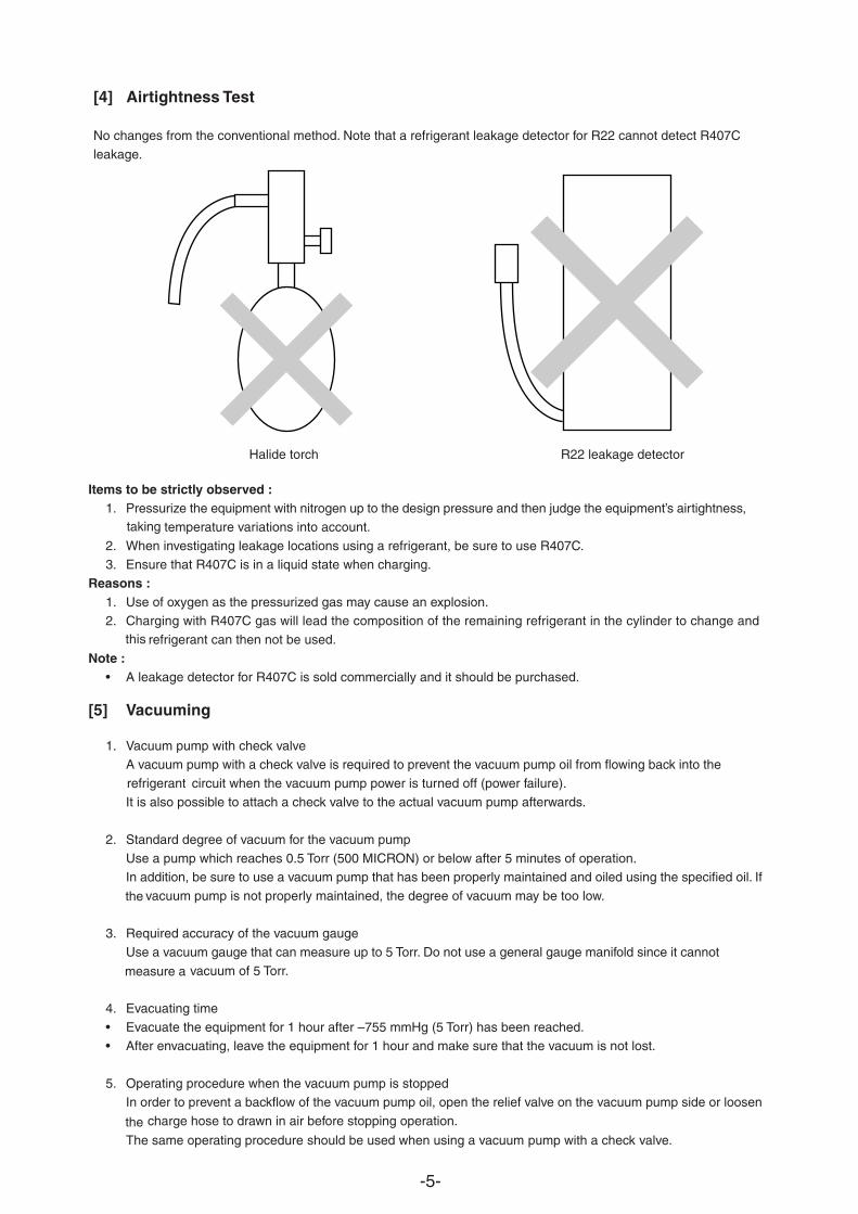
[4] Airtightness Test
No changes from the conventional method. Note that a refrigerant leakage detector for R22 cannot detect R407C
leakage.
Halide torch R22 leakage detector
Items to be strictly observed :1. Pressurize the equipment with nitrogen up to the design pressure and then judge the equipment’s airtightness,
temperature variations into account.taking
2. When investigating leakage locations using a refrigerant, be sure to use R407C.3. Ensure that R407C is in a liquid state when charging.
Reasons :1. Use of oxygen as the pressurized gas may cause an explosion.2. Charging with R407C gas will lead the composition of the remaining refrigerant in the cylinder to change and
refrigerant can then not be used.this
Note :• A leakage detector for R407C is sold commercially and it should be purchased.
[5] Vacuuming
1. Vacuum pump with check valveA vacuum pump with a check valve is required to prevent the vacuum pump oil from flowing back into the
circuit when the vacuum pump power is turned off (power failure).refrigerant
It is also possible to attach a check valve to the actual vacuum pump afterwards.
2. Standard degree of vacuum for the vacuum pump
Use a pump which reaches 0.5 Torr (500 MICRON) or below after 5 minutes of operation.In addition, be sure to use a vacuum pump that has been properly maintained and oiled using the specified oil. If
vacuum pump is not properly maintained, the degree of vacuum may be too low.the
3. Required accuracy of the vacuum gauge
Use a vacuum gauge that can measure up to 5 Torr. Do not use a general gauge manifold since it cannot
vacuum of 5 Torr.measure a
4. Evacuating time
• Evacuate the equipment for 1 hour after –755 mmHg (5 Torr) has been reached.• After envacuating, leave the equipment for 1 hour and make sure that the vacuum is not lost.
5. Operating procedure when the vacuum pump is stoppedIn order to prevent a backflow of the vacuum pump oil, open the relief valve on the vacuum pump side or loosen
charge hose to drawn in air before stopping operation.theThe same operating procedure should be used when using a vacuum pump with a check valve.
-6-
Cylin-der
Cylin-der
Valve Valve
Liquid Liquid
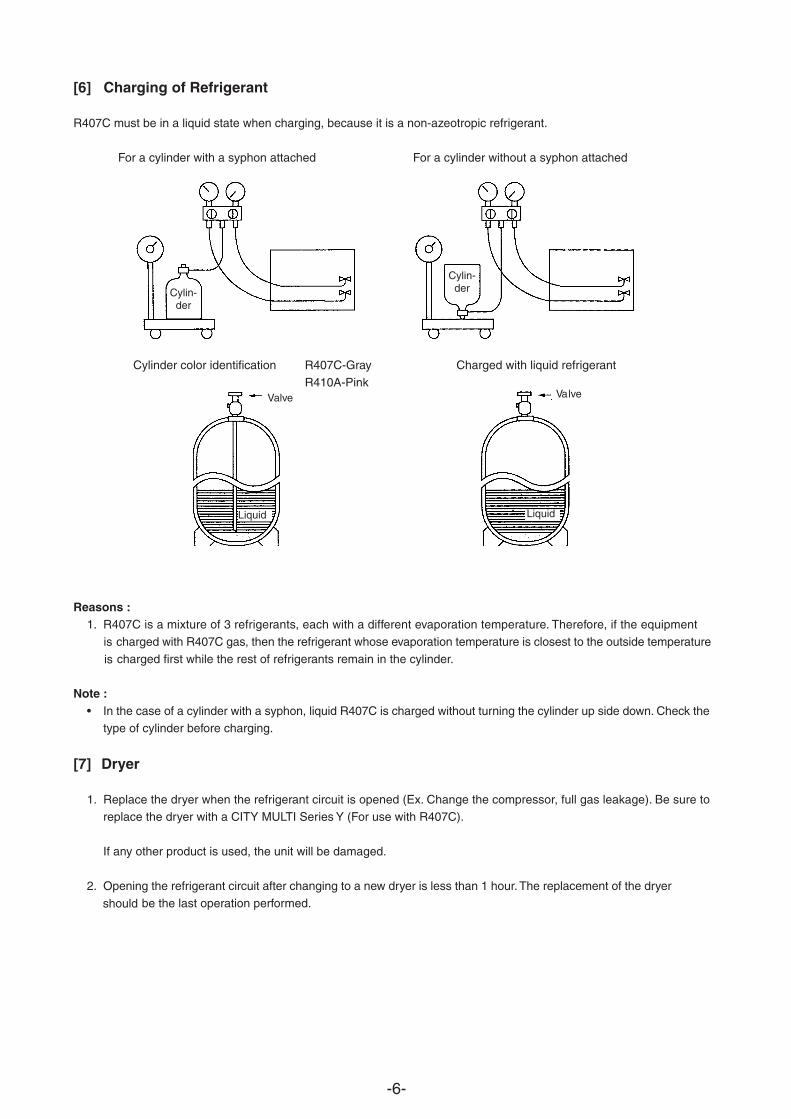
[6] Charging of Refrigerant
R407C must be in a liquid state when charging, because it is a non-azeotropic refrigerant.
For a cylinder with a syphon attached For a cylinder without a syphon attached
Cylinder color identification R407C-Gray Charged with liquid refrigerant
R410A-Pink
Reasons :1. R407C is a mixture of 3 refrigerants, each with a different evaporation temperature. Therefore, if the equipment
charged with R407C gas, then the refrigerant whose evaporation temperature is closest to the outside temperature ischarged first while the rest of refrigerants remain in the cylinder.
Note :• In the case of a cylinder with a syphon, liquid R407C is charged without turning the cylinder up side down. Check the
type of cylinder before charging.
[7] Dryer
1. Replace the dryer when the refrigerant circuit is opened (Ex. Change the compressor, full gas leakage). Be sure toreplace the dryer with a CITY MULTI Series Y (For use with R407C).
If any other product is used, the unit will be damaged.
2. Opening the refrigerant circuit after changing to a new dryer is less than 1 hour. The replacement of the dryer
be the last operation performed.should
is
-7-
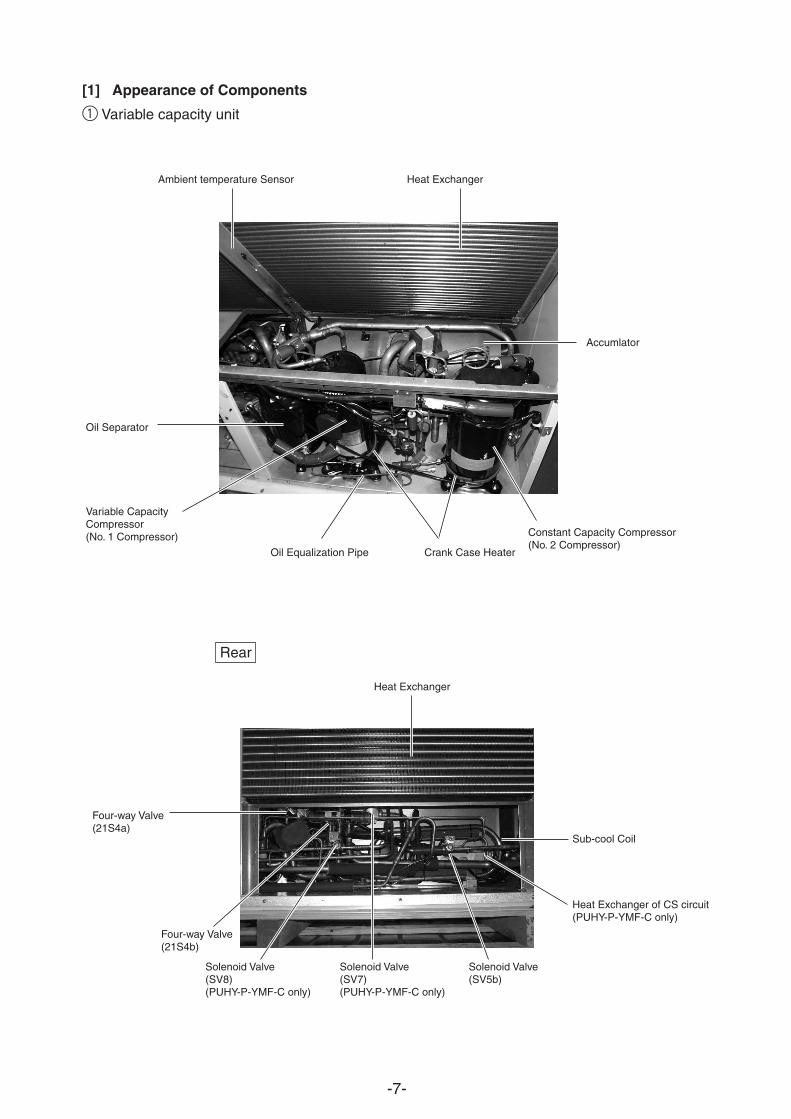
[1] Appearance of Components
Heat Exchanger
Sub-cool Coil
Heat Exchanger of CS circuit(PUHY-P-YMF-C only)
Solenoid Valve(SV5b)
Solenoid Valve(SV7)(PUHY-P-YMF-C only)
Solenoid Valve(SV8)(PUHY-P-YMF-C only)
Four-way Valve(21S4b)
Four-way Valve(21S4a)
Heat ExchangerAmbient temperature Sensor
Accumlator
Constant Capacity Compressor(No. 2 Compressor)
Crank Case HeaterOil Equalization Pipe
Variable CapacityCompressor (No. 1 Compressor)
Oil Separator
1 Variable capacity unit
Rear
-8-
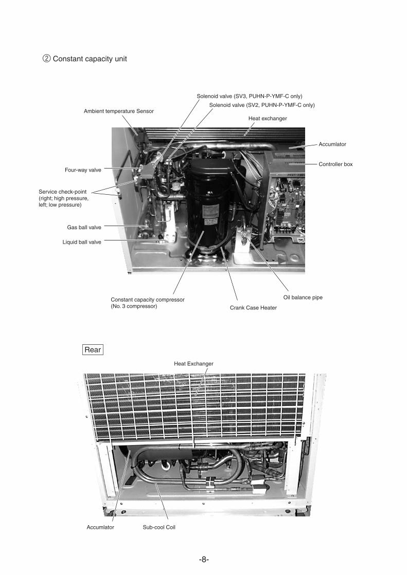
Heat Exchanger
Sub-cool CoilAccumlator
Solenoid valve (SV3, PUHN-P-YMF-C only)
Ambient temperature Sensor
Accumlator
Controller box
Oil balance pipe
Crank Case Heater
Constant capacity compressor (No. 3 compressor)
Liquid ball valve
Four-way valve
Gas ball valve
Service check-point(right; high pressure, left; low pressure)
2 Constant capacity unit
Rear
Solenoid valve (SV2, PUHN-P-YMF-C only)
Heat exchanger
-9-
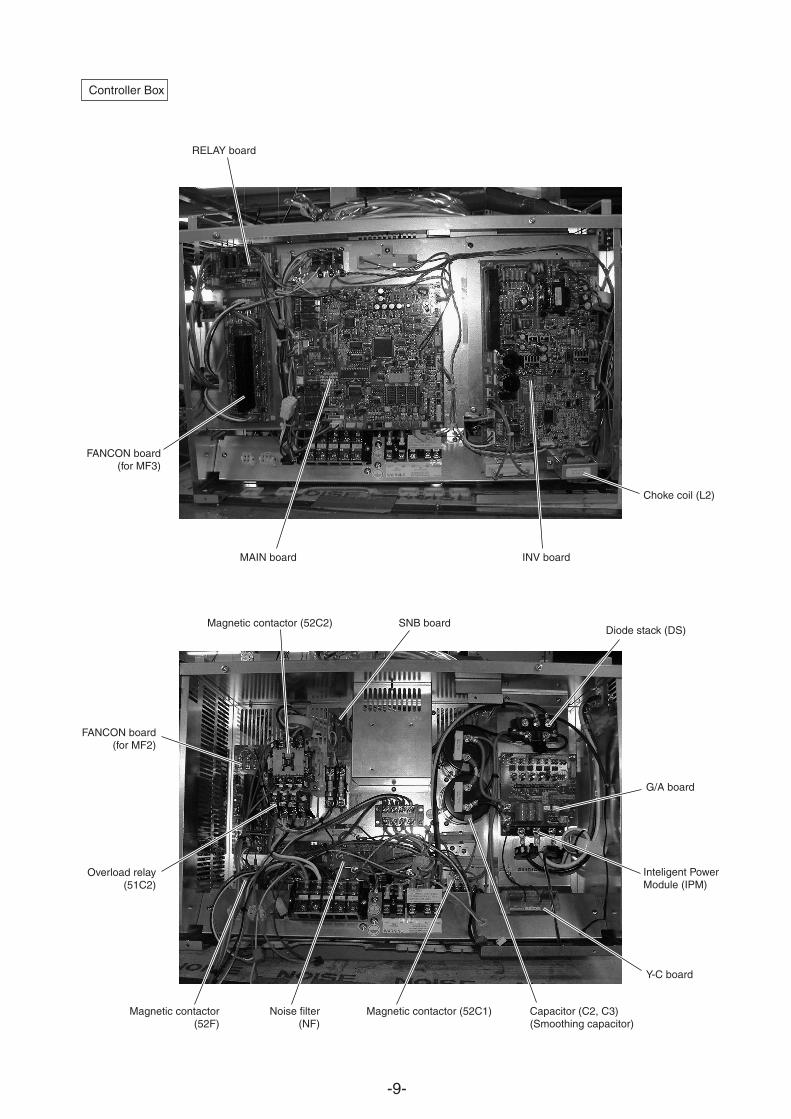
Controller Box
RELAY board
FANCON board(for MF3)
INV boardMAIN board
Choke coil (L2)
Inteligent PowerModule (IPM)
G/A board
Y-C board
SNB boardDiode stack (DS)
Magnetic contactor (52C2)
Magnetic contactor (52C1)Magnetic contactor (52F)
Overload relay (51C2)
FANCON board(for MF2)
Capacitor (C2, C3)(Smoothing capacitor)
Noise filter(NF)
-10-
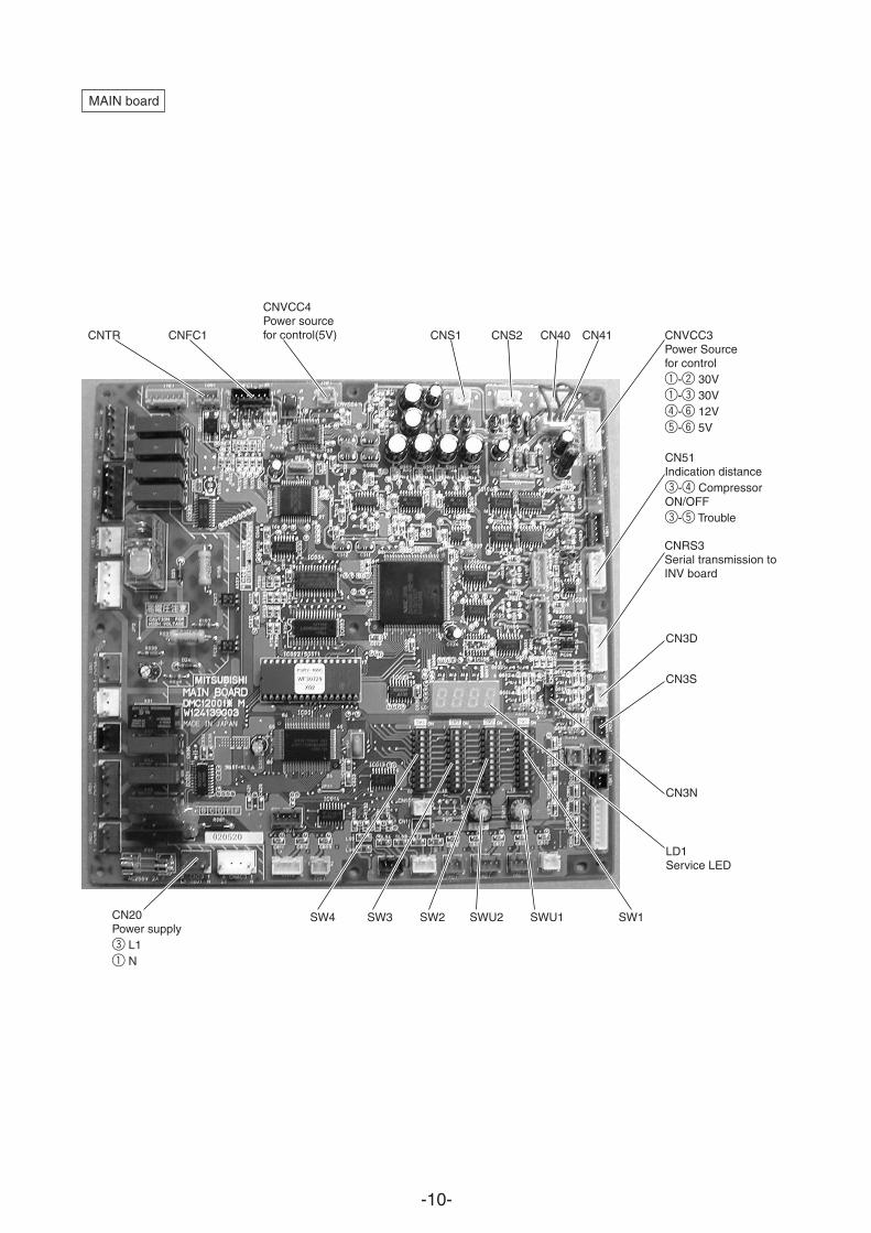
CNTR CNFC1 CNS1 CNS2 CN40 CN41 CNVCC3Power Sourcefor control1-2 30V1-3 30V4-6 12V5-6 5V
CNVCC4Power sourcefor control(5V)
CN51Indication distance3-4 CompressorON/OFF3-5 Trouble
CNRS3Serial transmission to INV board
CN3D
CN3S
CN3N
LD1Service LED
SW1SWU1SWU2SW2SW3SW4CN20Power supply3 L11 N
MAIN board
-11-
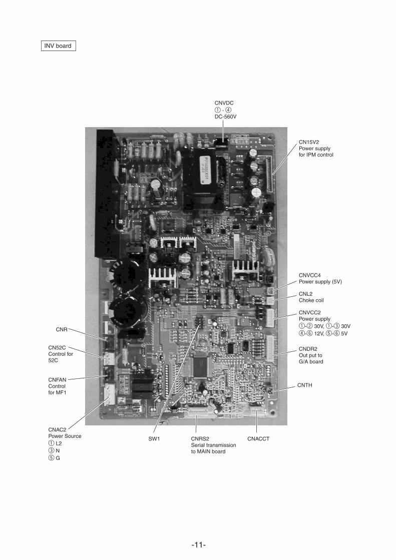
CNAC2Power Source1 L23 N5 G
CNFANControlfor MF1
CN52CControl for 52C
CNR
CNVDC1 - 4DC-560V
CN15V2Power supplyfor IPM control
CNVCC4Power supply (5V)
CNL2Choke coil
CNDR2Out put toG/A board
CNVCC2Power supply1-2 30V, 1-3 30V4-6 12V, 5-6 5V
CNTH
CNACCTCNRS2Serial transmission to MAIN board
SW1
INV board
-12-
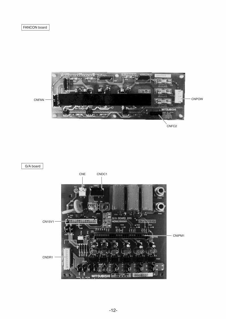
FANCON board
G/A board
CNFAN
CNFC2
CNPOW
CNE CNDC1
CN15V1
CNDR1
CNIPM1
-13-
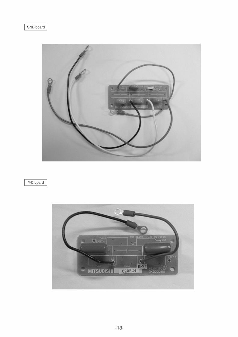
Y-C board
SNB board
-14-
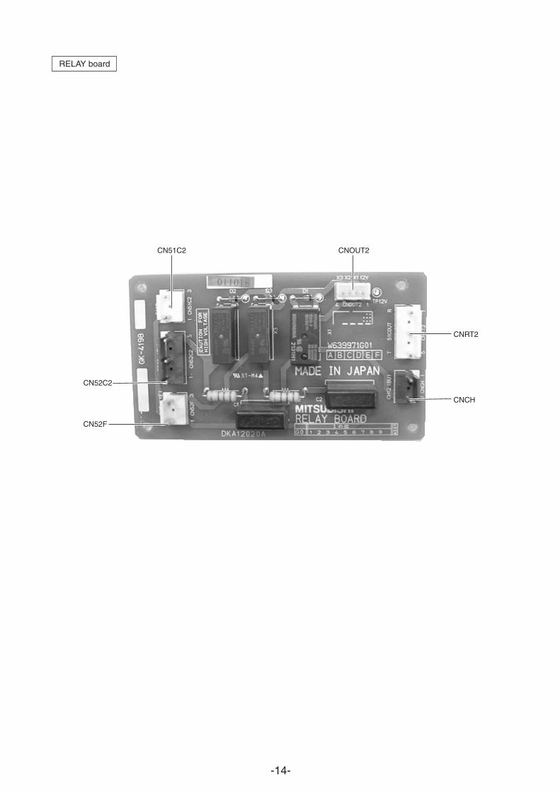
RELAY board
CNRT2
CNCH
CN52C2
CN52F
CN51C2 CNOUT2
-15-
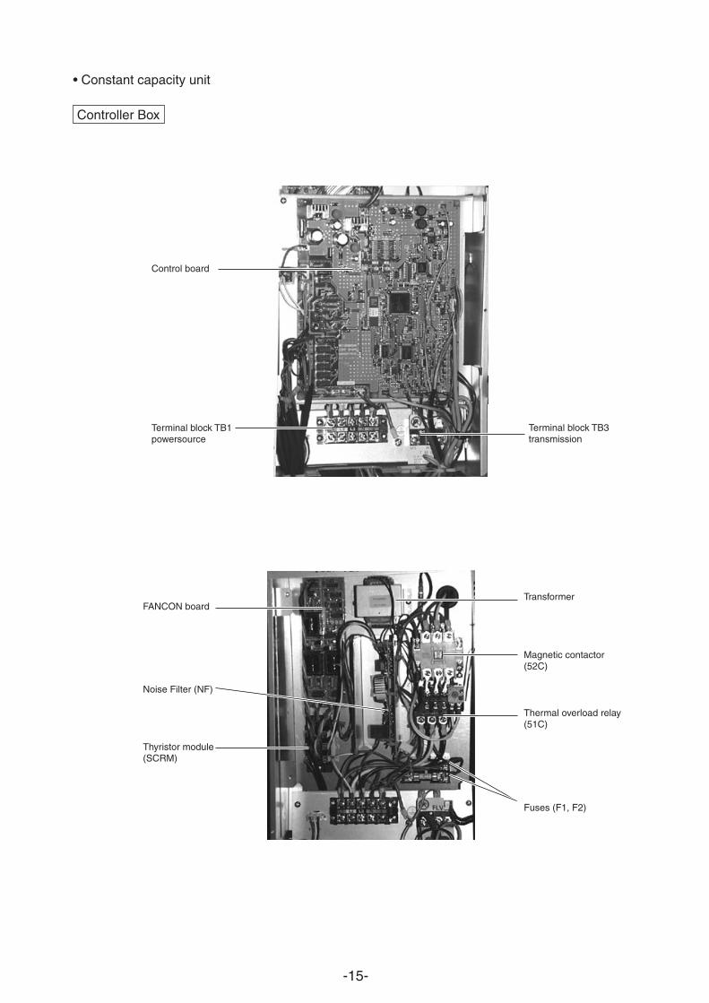
• Constant capacity unit
Transformer
Magnetic contactor(52C)
Thermal overload relay(51C)
Fuses (F1, F2)
Thyristor module(SCRM)
FANCON board
Noise Filter (NF)
Terminal block TB3transmission
Terminal block TB1powersource
Controller Box
Control board
-16-
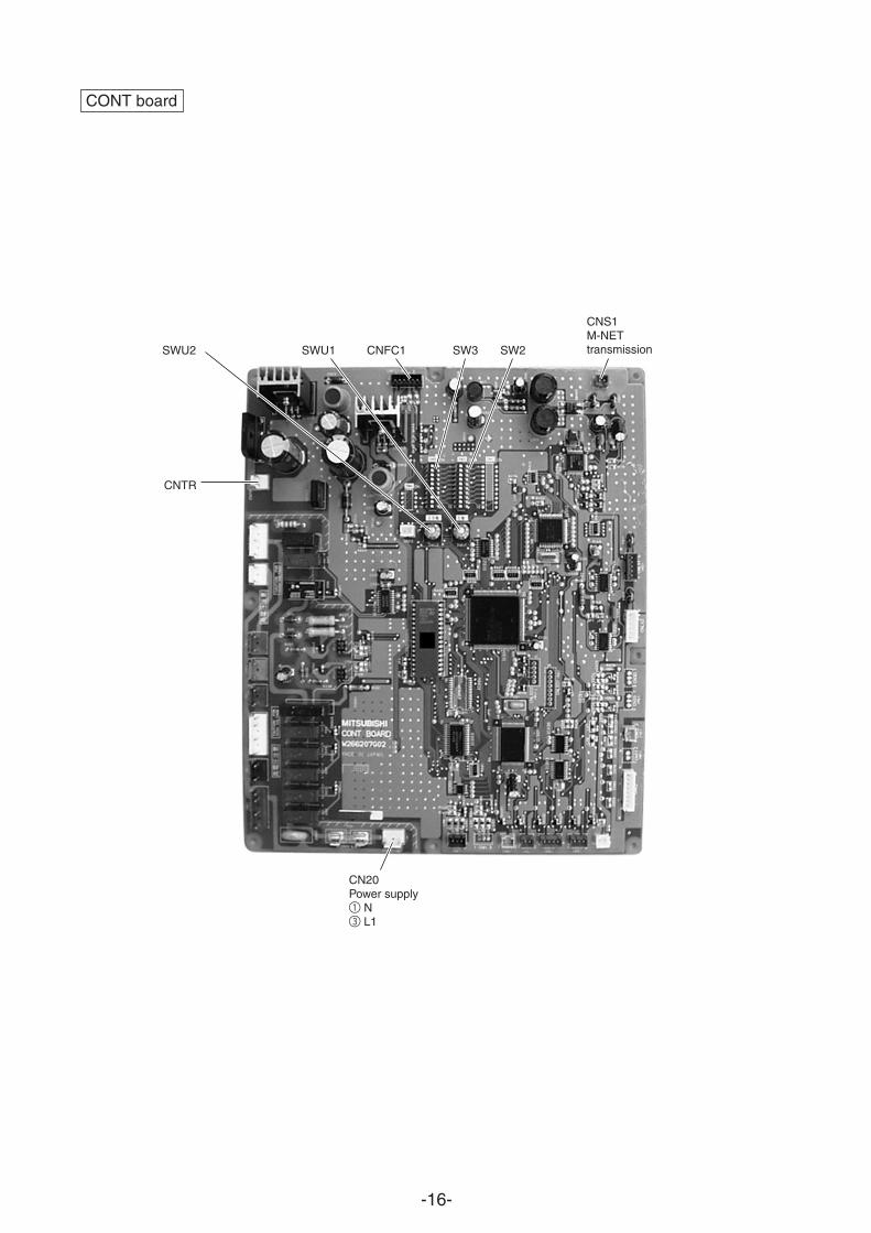
CONT board
CNTR
SWU2 SWU1 SW3 SW2
CNS1M-NETtransmissionCNFC1
CN20Power supply1 N3 L1
-17-
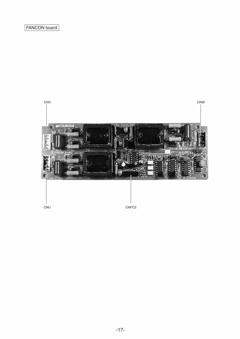
FANCON board
CNWCNV
CNU CNFC2
-18-
CP
1
CP
5
ST
6
SV
1
SLE
V
CP
4
No.
1C
omp.
TH
8
HE
X2a
TH
5
SV
5b
HE
X1a
TH
6
HE
X2b
HE
X1b
21S
4b
21S
4a
CJ1 63
HS
ST
5
SV
4
SV
6
TH
11
63H
1
CV
1
CV
3
O/S
CJ2
BV
1
ST
1
MA
SA
TH
2
CP
2
ST
2
BV
2
BV
3
ST
8
ST
9
TH
3S
T3
TH
7S
T7
TH
9
T10
a
T10
b
LEV
1
SC
C
TH
4S
T4
CJ3
63H
2
CV
2
CP
3aS
V22
SV
32
TH
12C
P3b
No.
2C
omp.
T
here
are
SV
22,S
V32
onl
y fo
r P
UH
Y-50
0YM
F-C
.
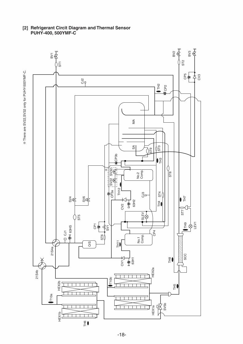
[2] Refrigerant Circit Diagram and Thermal SensorPUHY-400, 500YMF-C

-19-
BV
3T
H7
TH
8T
H5
TH
6
CJ1
O/S
63H
S
TH
11
HE
XF
1
HE
XF
2H
EX
B2
HE
XB
1
CJ2
CV
1
SV
4
SV
1CP
1
TH
4T
H3
CP
4
CP
7
BV
2
BV
1
TH
12
Com
p2C
omp1
CV
2
SA
MA
CP
3a
SV
6
LEV
1
63H
163
H2
21S
4a
21S
4b
SV
5b
SV
22
SV
32
ST
5
ST
6
CP
3b
ST
3S
T4
ST
9
ST
8
TH
9aS
T2
ST
1
CJ3
ST
7
TH
9b
TH
2
Dri
erC
P2
TH
10c
63LS
CV
3
CP
5
TH
10b
TH
10a
SLE
V
SV
8
SV
7
T
here
are
SV
22,S
V32
onl
y fo
r P
UH
Y-P
500Y
MF
-C.
PUHY-P400, 500YMF-C
-20-
21S
4b
HE
X1b
TH
6
TH
10a
HE
X2b
21S
4a
CJ1
63H
S
ST
5
SV
4
SV
6
TH
10b
O/S S
T6
CP
1
SV
1
HE
X1a
HE
X2a
SV
5b
TH
5
CV
1
63H
1
TH
11 Comp
1Co
mp2
TH
8S
T10
CP
4
SLEV
TH
4S
T4
ST8
CJ3
63H
2
CV
2
CP3a
TH
12
SV22
S
V32
CP3b S
T9S
AM
A
TH
3S
T3
TH
9
LEV
1
ST
7T
H7
TH
2C
P2C
J2
SC
C
SC
C
ST
1BV
1
Dis
trib
uter
(G
as)
Indo
or u
nit
BV
2
ST
2
BV
3
BV
1
ST
1
CJ2
63LS
MA
SA
CP
3
ST
8
ST
4T
H4S
T3
TH
3
CP
1
SV
1
ST
6CV
1
O/S
CJ1
ST
5S
V4
21S
4
TH11
63H
Comp
1
TH
10a
TH
6
HE
X1
HE
X2
TH
5T
H8
ST
10
TH
9
LEV
1S
T7
TH
7
CV
2B
V2
SV
5bC
P5
LEV
2
ST
2
TH
10b
BV
3
Oil
bala
nce
pipe Dis
trib
uter
(Li
quid
)
ST
9
PU
HY-
400,
500Y
MF
-C
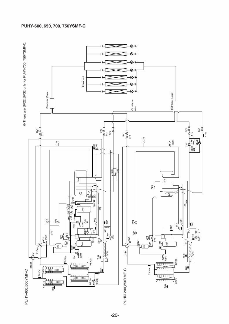
PU
HN
-200
,250
YM
F-C
T
here
are
SV
22,S
V32
onl
y fo
r P
UH
Y-70
0, 7
50Y
SM
F-C
.
CV
3
CP
5
PUHY-600, 650, 700, 750YSMF-C
-21-
Dis
trib
utor
BV
3
TH
6
TH
7
TH
8T
H5
CJ1
O/S
63H
S
TH
11
HE
XF
1H
EX
B1
CJ2
CV
1
SV
4
SV
1S
V7
SV
8
CP
1
TH
4T
H3
CP
4
BV
2
BV
1
TH
12
Com
p2C
omp1
HE
XF
2H
EX
B2
CV
2
SA
MA
CP
3a
SV
6
LEV
1
63H
163
H2
21S
4a
21S
4b
SV
5b
SV
22
SV
32
ST
5
ST
6
CP3b
ST
3S
T4
ST
9
ST
8
TH
9aS
T2
ST
1
CJ3
ST
7
TH
9b
TH
2
Dri
erC
P2
TH
10c
63LS
CV
3
CP
5
TH
10b
TH
10a
Dis
trib
utor
TH
7
TH
5
O/S
TH
11
CJ2
SV
4
SV
1
CP
1
TH
4
TH
3
BV
2
BV
1
Com
p1
HE
X2
HE
X1
SV
5b
SA
MA
CP
3
LEV
1
63H
21S
4
CJ1
CV
1
BV
3
ST
1
ST
2
ST
5
ST
6
ST
9
ST
3
ST
4
ST
8
TH
10a
CV
2
CP
5
LEV
2
TH
6
63LS
ST
10
ST
7T
H9
TH
8
TH
10b
SV
3S
V2
SLE
V
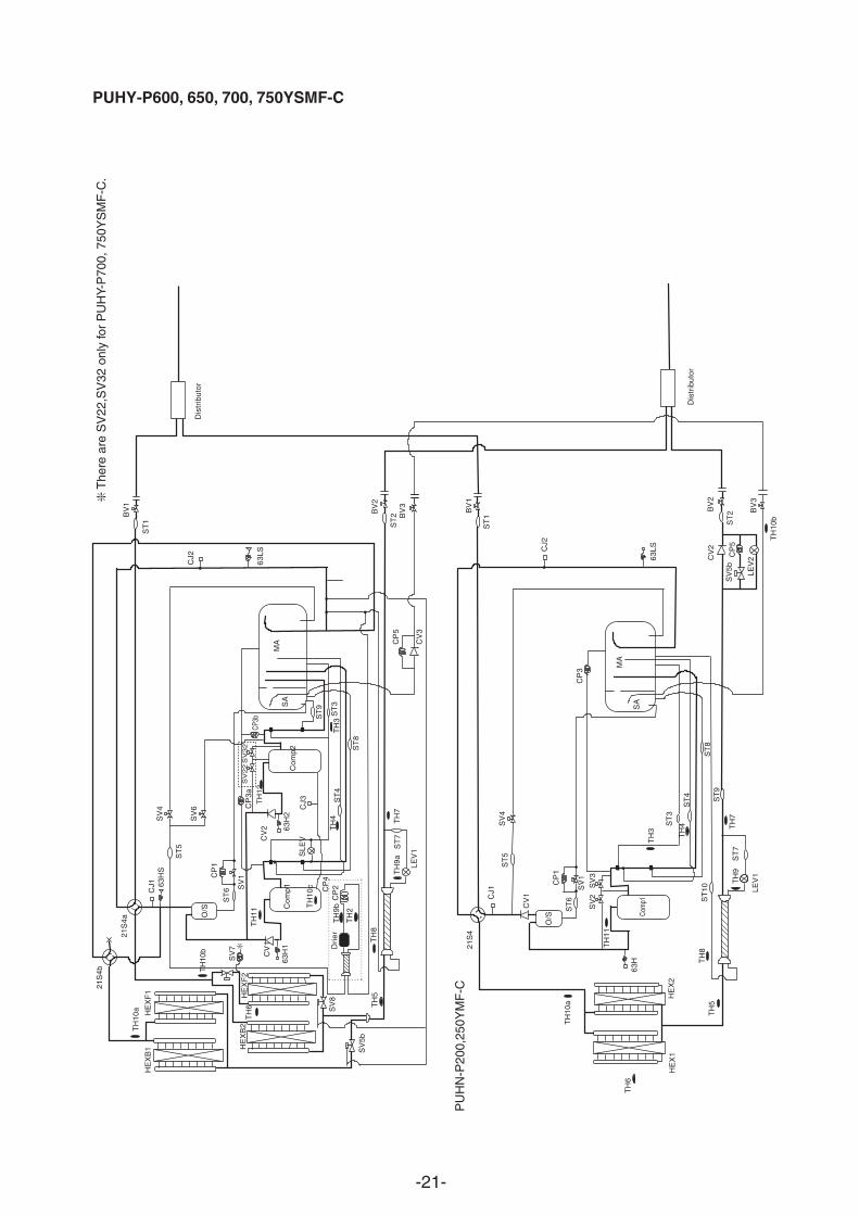
PUHY-P600, 650, 700, 750YSMF-C
The
re a
re S
V22
,SV
32 o
nly
for
PU
HY-
P70
0, 7
50Y
SM
F-C
.
PU
HN
-P20
0,25
0YM
F-C
-22-
Fa
n m
otor
(Hea
t exc
hang
er)
Fa
n m
otor
(Hea
t exc
hang
er)
TH12
MC
2
PU
HY
-(P
)500
YM
F-C
63H2
SV22 SV
32S
LEV
TH12
63H
2
MC
263
HS
MC
1
PU
HY
-(P
)400
YM
F-C
TH
4
SV
1 63H
1
Box
Con
trol
ler
Inve
rter
Oil
sepa
rate
r
TB
1AT
B3
TB
7
MA
IN b
oard
INV
boa
rd
RE
LAY
R7
L2
boar
d
FA
NC
ON
boar
dF
AN
CO
Nbo
ard
F3
52C
2
51C
2
52F
F5
F6
52C
1
TB
1B
DC
LS
NB
boar
d
R2+ C2 - C3+ -
R3
R1
R5
TH
HS C1
AC
CT
-U
MF
1
NF
G/A
boa
rd
IPM A
CC
T -
W
DS
ZN
R4
CN
05C
N04
(for
MF
3)(f
or M
F2)
TH
2
R6
TH
10a
TH
8
AC
CU
MU
LAT
OR
TH
3
21S
4bS
V5b
SV
4S
V6
LEV
1
TH
5
TH
6
21S
4a
*3
SV
8
SV
7TH
10b
TH
9a
DE
MA
ND
*2
*3*3
*2
MO
DE
CN
3D
HE
AT
Aut
oC
hang
eove
rN
orm
alC
OLL
OF
FO
FF
ON
OF
FO
N1-
21-
3O
N
MO
DE
CN
3NC
N3S
1-3
1-2
1-2
DE
MA
ND
NIG
HT
SN
OW
Ref
er to
the
serv
ice
hand
book
abou
t the
sw
itch
oper
atio
ns.
as c
onne
ctio
n w
ithP
UH
N-(
P)2
00/2
50Y
MF
-C
SW
4-6
ON
OF
F
13 2C
N3N
(3P
)
13 2C
N3S
(3P
)
12
34
CN
13(4
P)
TH10
bTH
10a
CN12
12
(2P
)
TH9b
LEV1
TH8
SV6
*150/6
0Hz
3N~
380/
400/
415V
Pow
er s
ourc
e
63H
1
T10 T
9SV
32
SV22
FB
4
X08
X04
CH
11
CH
3
CH
2S
SR
43 2
1
123CN
35(3
P)
M2
M1
SM2
M1
CN34
(6P
)
6 5 4 3 2 1 1 2
CN38
(3P)
X05
X07
X06
123456
(6P)
CN36
X09
123456
(6P)
CN37
(3P)
CN32
TB
7
TB
3
X01
X02
(3P
)C
NS
22
(2P
)C
NS
11
31
1
2
23 2 1
(3P
)CN
333
L1 L2 L3 N
PE
PEL1TB
1A
L2 L3 N
L1N
F L2 L3 N
1234B A
(4P
)CN
AC3
BO
X B
OD
Y
BOX
BODY
Ter
min
alB
lock
Noi
seF
ilter
Hig
h pr
essu
resw
itch
dete
ctio
n
Cra
nk c
ase
heat
er(C
ompr
esso
r)
Indo
or a
ndC
onne
ct to
rem
ote
cont
rolle
r
8A F
600VA
C
F6
600VA
C8A
F
F5
SV5b
21S4a
SV4
SV1
21S4b
X10
L3L2L1
EART
HSN
B b
oard
X12
X11
Rel
ay b
oard
TH2
TH7
TH5
TH6
TH3
TH4
63LS
63H
STH
11TH
9aTH
10c
TH12
SLEV
52C1
CH
12
52F
52C2
51C
2CN
51C2
(3P
)
CN52
C2 (
5P)
CN52
F (
3P)
CNCH
(3P
)
CNRT
2 (
5P)
CNOU
T2 (
4P)
CNRT
1(5
P)
CN
OU
T1
(6P
)
MF1
65
FB
3
1 2 3CN
X10
(3P
)
Mot
or(C
ompr
esso
r)
52F
12
34
56
L1L2
L3
(6P
)CN
FC1
F01 2
50VA
C 6.3
A F
F03 2
50VA
C 6.3
A F
F02 2
50VA
C 6.3
A F
N
CNPO
W(5
P) C
NF
C2
(6P
)
123456
123456
V WNU
MF2
1 2 3 4 5
1 2 3 4
51
23
4
Fan
con
trol
boa
rd(F
anco
n bo
ard)(5
P)
CNFA
NCN
04
F01 2
50VA
C 6.3
A F
F03 2
50VA
C 6.3
A F
F02 2
50VA
C 6.3
A F
N
CNPO
W(5
P)
CN
FC
2(6
P)
123456
V WNU M
F3
1 2 3 4 5
1 2 3 4
51
23
4
Fan
con
trol
boa
rd(F
anco
n bo
ard)
L1L2
L3
(5P
)CN
FAN
FB
5
Bla
ckW
hite
Red
Con
trol
ler
Box
Inve
rter
circu
it
circu
itde
tect
ion
(MA
IN b
oard
)C
ontr
ol c
ircui
t boa
rd5:
Tro
uble
4:C
ompr
esso
r O
N/O
FF
SN
OW
NIG
HT
(IN
V b
oard
)P
ower
circ
uit b
oard
Gat
e am
p bo
ard
(G/A
boa
rd)B
lack
Whi
teR
ed
Mot
or(C
ompr
esso
r)
Dio
dest
ack
Ter
min
alB
lock
BOX B
ODYBO
X BOD
Y
BOX B
ODY
X10
2A F
1A F
2A F
(3P
)C
N20
DS
CN
TR
1
12
3
T01
F3
250V
AC
CN
TR
(3P
)
L1L2
L3N
L1TB
1B
L2 L3 NNL3L2L1
RedWhiteBlack
12
34
5
CN
LV2
(5P
)1
23
(3P
)C
N03
12
34
CN
05(4
P)
CN
E(2
P)
21
(14P
)C
N15
V2
(7P
)CN
RS3
(6P
)CN
VCC2
(6P
)CN
VCC3
(2P
)CN
VCC4
(7P
)CN
RS2
X01
321651 2 3 4 5 6 7 1 2 1 432
98
76
43
21
12
3
VM
C1 W
U
(4P
)C
NV
DC
(3P
)C
N52
C
(5P
)C
NA
C2
(2P
)CN
VCC4
250V
ACF
01
651 2 3 4 5 6 7 1 2 1 432
CNDC
1(4
P)
12
34
12
34
59
87
61
23
45
CN
DR
2(9
P)
1413
1110
121210
1113
145
43
21
67
89
54
32
16
78
9
5
1 2 3 4
UV
W
P N
IPM
CN
DR
1(9
P)
CN
15V
1(1
4P)
4
CNAC
CT(4
P)
54
3
1
21
67
8
3
12
12
31
23
12
34
5
2
3 42 51
1
CN
3D(3
P)
32
CN51
(5P
)
12V
F1
250V
AC
12
3BlackWhiteRed
12
3
~ ~-
~
+Z
NR
4 C1
R5
R1 52
C1
++
DC
L
C2
C3
R2
R3
CN
02(8
P)
CN
01(2
P)
CN
H(3
P)
CN
L(3
P)
CN
LV1
(5P
)CN
06CN
09
12
(2P
)1
2(2
P)
3
(2P
)CN
07 21
UW
MC
2V
1 3 5642
65
43
21
52C
251
C2
-W
ACCT
-U
ACCT
12345 123456
12345 4 123
X02
X03
321 1 2 3 54 1 2 3 1 2 3
52C
2X
01
9695
A2
A1
1314
A1
A2
CN
FA
N(3
P)
32
1X
02
L2R7
THHS
R6
(2P
)CN
30V
(2P
)CN
L2
12
12
31
21
2(2
P)
CNTH
(3P
)CN
R
BOX B
ODY
FB
2F
B1
T1T
2T3T
4T5T
6
T8
BO
X B
OD
Y
63H
2
T7
87654321
AB
X12
SV7
SV8
X11
CN
06
Y-C
bo
ard
CN
05
FLA
G8
FLA
G7
FLA
G6
FLA
G5
FLA
G4
FLA
G3
FLA
G2
FLA
G1
sor r
unCo
mpres
-
52F
SV
6S
V4
SV
121
S4a
FLA
G8
FLA
G7
FLA
G6
FLA
G5
FLA
G4
FLA
G3
FLA
G2
ON
:1O
FF:0
<O
pera
tion
of s
elf-
diag
nosi
s sw
itch(
SW
1)an
d LE
D d
ispl
ay>
FLA
G8
alw
ays
light
s at
mic
roco
mpu
ter
pow
er O
N
Alw
ays
light
ing
52C
2
Dis
play
at L
ED
ligh
ting
(blin
king
) Rem
arks
SW
1 op
erat
ion
Durin
gFL
AG
1D
ispl
ay
Chec
k di
spla
y1(B
linki
ng)
Rel
ay o
utpu
t di
spla
y(L
ight
ing)
<LE
D d
ispl
ay>
LD1
Dis
play
the
addr
ess
and
erro
r co
de b
y tu
rns
*Ple
ase
refe
r to
the
serv
ice
hand
book
abo
ut o
ther
sw
itch
setti
ngs
of L
ED
dis
play
.
1234
5678
910
ON
:1O
FF:0
(at f
acto
ry s
hipm
ent)
1234
5678
910
SV22
/32
*1
52C
1
CH
2,3
<C
ontr
olle
r bo
x in
tern
al la
yout
>(U
psid
e)
(Fro
nt)
(Und
ersi
de)
21S
4bS
V5b
SV
5b is
clo
sed
whe
n F
LAG
3 is
turn
ed O
N.
<D
iffer
ence
of a
pplia
nce>
<U
nit i
nter
nal l
ayou
t>
Nam
eA
pplia
nce
"*1"
is n
ot e
xist
edP
UH
Y-P
400Y
MF
-CP
UH
Y-P
500Y
MF
-CA
ll ex
ists
PU
HY
-400
YM
F-C
PU
HY
-500
YM
F-C
"*1"
,"*2
" an
d "*
3" a
re n
ot e
xist
ed"*
2" a
nd "
*3"
are
not e
xist
ed
NO
TE
:Mar
kin
dica
tes
term
inal
bed
conn
ecto
r bo
ard
inse
rtio
n co
nnec
tor
Ter
min
alT
1~10
Inte
llige
nt p
ower
mod
ule
IPM
Cho
ke c
oil(T
rans
mis
sion
)L2
Hig
h pr
essu
re s
witc
h63
H1,
263
LSLo
w p
ress
ure
sens
orH
igh
pres
sure
sen
sor
63H
SEl
ectro
nic
expa
nsio
n va
lve(
SC c
oil)
LEV
1
FB
1~5
Fer
rite
core
Ear
th te
rmin
al
X1,
2,4~
12A
ux. r
elay
SS
RC
H2,
3S
olid
sta
te r
elay
Cor
d he
ater
CH
11,1
2C
rank
cas
e he
ater
(Com
pres
sor)
LDA
ccum
ulat
or li
quid
leve
l det
ect
(Inv
erte
r m
ain
circ
uit)
Elec
troni
c ex
pans
ion
valve
(Oil r
etur
n)S
LEV
4-w
ay v
alve
21S
4a,4
bF
an m
otor
(R
adia
tor
pane
l)M
F1
52F
Mag
netic
con
tact
or(F
an m
otor
)O
verlo
ad r
elay
51C
2
Mag
netic
con
tact
or52
C2
Var
isto
rZ
NR
4C
urre
nt S
enso
rA
CC
T-U
,W
Sym
bol
Nam
e
Radia
tor pa
nel te
mp. d
etect
TH
HS
(Hea
t exc
hang
er c
apac
ity c
ontro
l)Co
mpr
esso
r she
ll tem
p.T
H10
cS
olen
oid
valv
eS
V5,
6,7,
8T
H10
bG
as p
ipe
tem
p.(H
ex o
utle
t)T
H10
a4,
6S
V1,
22,3
2S
olen
oid
valv
eCo
mpos
ition s
ensin
g tem
p.T
H9b
LEV1
temp
.detec
t(Entt
ance
area)
TH
9a
(Byp
ass
exit
area
)T
H8
SC
coi
l tem
p.de
tect
TH
7(L
iqui
d ex
it ar
ea)
SC
coi
l tem
p.de
tect
OA
tem
p. d
etec
tT
H6
52C
1M
agne
tic c
onta
ctor
Pipe t
emp.
detec
t(Hex
outle
t)T
H5
TH
4tem
p. de
tect
Upp
erT
H3
Accu
murat
or liq
uidLo
wer
DC
L(P
ower
fact
or im
prov
emen
t)Sa
turati
on ev
apo.
temp.
detec
tT
H2
DC
rea
ctor
Disch
arge p
ipe te
mp. d
etect
The
rmis
tor
TH
11,1
2S
ymbo
lN
ame
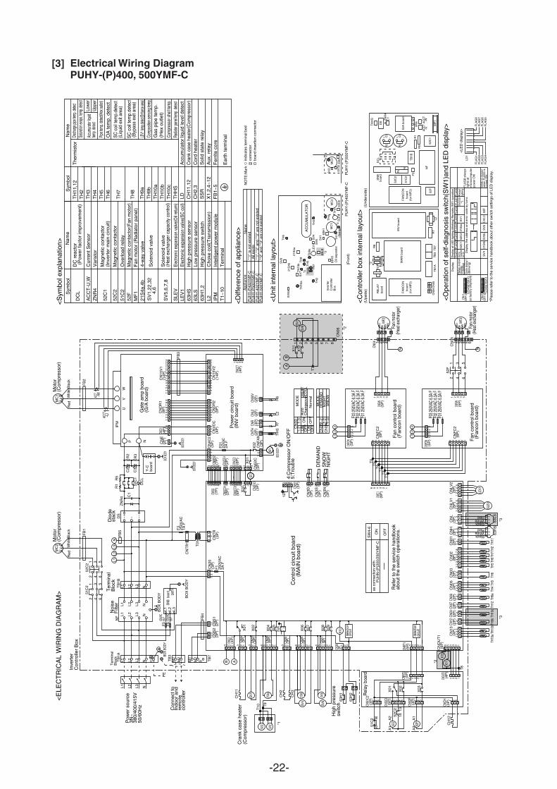
<S
ymbo
l exp
lana
tion>
<E
LEC
TR
ICA
L W
IRIN
G D
IAG
RA
M>
TH
9b TH
7
63LS *3
TH11 TH
10c
*3
X12
X11
T01
*2
[3] Electrical Wiring DiagramPUHY-(P)400, 500YMF-C
-23-
TE
RM
INA
LT
1,T
2
T1 T2
Box
bod
y
Box
bod
y
1 2 3N
F
an m
otor
(Hea
t exc
hang
er)
V
CN
04
MF
WUC
NM
F
Mod
el 2
00:2
4AM
odel
250
:27A
*1
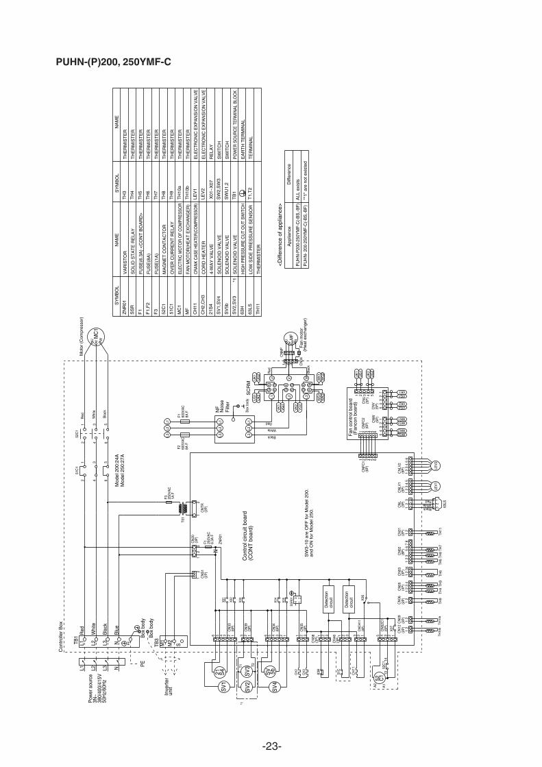
<D
iffer
ence
of a
pplia
nce>
*1
App
lianc
eD
iffer
ence
PU
HN
-P20
0·25
0YM
F-C
(-B
S,-B
F)
ALL
exi
sts
PU
HN
- 200
·250
YM
F-C
(-B
S,-B
F)
"*1"
are
not
exi
sted
L2
L1
L3
PE
5
GKG K
GKG K
GKG K
WG
2
UK
1U
G2
SC
RM
UG
1U
K2
WK
1W
K2
W
WG
1
VK
1V
G1
VK
2V
G2
VU
L1
Red
L2
F2
L1 L3
L2
F1 600V
AC
8A F
L3
4
1 2 3
600V
AC
8A F
Bla
ck
Red
UG
24
White
Black
5
UG
1U
K1
UK
25 6
54
32
11
23
45
321 WG2
Fan
con
trol
boa
rd (
Fan
con
boar
d)
WK2
WG1WK1
VG2VK2
VG1VK1
an
d O
N f
or
Mo
de
l 25
0.
SW
3-1
0 a
re O
FF
fo
r M
od
el 2
00
.
12
14
21
32
32
41
12
36
78
12
12
31
23
45
12
1
34
52 3 4 5 6
CN
09(2
P)
CN
06(2
P)
1
1
3
CN
20(3
P)
2
CN
FC1
(6P
)
2
3
21 C
NS
1(2
P)
1 2 3
12
CN
38(3
P)
X01
NNL3
Pow
er s
ourc
e3N
~38
0/40
0/41
5V50
Hz/
60H
z
Con
trol
circ
uit b
oard
(CO
NT
boa
rd)
LEV
2
L2
F1 250V
AC
6.3A
F
63H
TH11
TH7
TH8
TH5
TH6
TH3
TH4
TH9
12
3BlackWhiteRed
63LS
L1
LEV
1
PETB
1
Whi
te
Red
Bla
ck
Blu
e
Inve
rter
unit
Box
bod
y
TB3
M1
M2
T01
F3 250V
AC
1A F
Whi
teU WM
C1
V
Mot
or (
Com
pres
sor)
Red Bla
ck
CN
05(4
P)
CN
03(3
P)
CN
02(8
P)
CN
01(2
P)
CN
L(3
P)
CN
33(6
P)
CN
LV1
(5P
)
CN
TR(2
P)
CN
LV2
(6P
)
Con
trol
ler
Box
CN
W(5
P)
CN
V(5
P)
CN
FC2
(6P
)C
NU
(5P
)
1 3 5642
65
43
21
CN
12
TH10
b
12
(2P
)
TH10
a
1 2 3 3 2 1 5 4 3 2 1
6
6 5 4
S
X02
SV
1
51C
CN
46(3
P)
CN
CH
11(3
P)
CH
11 52C
1C
N52
C1
(5P
)
X06
X07
52C
151
C1
1314
A1A2
Det
ectio
nci
rcui
t
Det
ectio
nci
rcui
t
ZNR
01L1
L2L3
L1L2
L3
CH
3
CH
2
X05
X04
SS
R01
123
4
321123456
(6P
)C
N34
(3P
)C
N35
3C
N39
(3P
)2 1
X03
SV
3 S
V2
SV
4 S
V 5
b
21
S4
52
C1
NF
Noi
se
Filt
er
TH
ER
MIS
TE
R
SV
2,S
V3
SO
LEN
OID
VA
LVE
21S
4
MF
MC
1
52C
1
SS
R
CH
11
CH
2,C
H3
ZN
R01
SV
5b
63H
63LS
SV
1,S
V4
TH
11
TH
3
TH
4
TH
5
TH
6
TH
7
TH
8
TH
10a
TH
10b
TH
9
X01
~X
07
SW
2,S
W3
SW
U1,
2
TB
1
LEV
1
LEV
2
TH
ER
MIS
TE
R
F3
TH
ER
MIS
TE
R
TH
ER
MIS
TE
R
TH
ER
MIS
TE
R
ELE
CT
RO
NIC
EX
PA
NS
ION
VA
LVE
RE
LAY
SW
ITC
H
SW
ITC
H
PO
WE
R S
OU
RC
E T
ER
MIN
AL
BLO
CK
EA
RT
H T
ER
MIN
AL
TH
ER
MIS
TE
R
TH
ER
MIS
TE
R
TH
ER
MIS
TE
R
LOW
SID
E P
RE
SS
UR
E S
EN
SO
R
HIG
H P
RE
SS
UR
E C
UT
OU
T S
WIT
CH
SO
LEN
OID
VA
LVE
4-W
AY
VA
LVE
CO
RD
HE
AT
ER
CR
ANK
CAS
E H
EATE
R(C
OM
PRES
SOR
)
FA
N M
OT
OR
(HE
AT
EX
CH
AN
GE
R)
ELEC
TRIC
MO
TOR
OF
CO
MPR
ESSO
R
OV
ER
CU
RR
EN
T R
ELA
Y
MA
GN
ET
CO
NT
AC
TO
R
FU
SE
(1A
)
SO
LID
ST
AT
E R
ELA
Y
VA
RIS
TO
R
TH
ER
MIS
TE
R
ELE
CT
RO
NIC
EX
PA
NS
ION
VA
LVE
TH
ER
MIS
TE
R
NA
ME
SY
MB
OL
F1,
F2
FU
SE
(8A
)
F1
FU
SE
(6.3
A)
<C
ON
T B
OA
RD
>
SY
MB
OL
NA
ME
SO
LEN
OID
VA
LVE
51C
1
PUHN-(P)200, 250YMF-C
-24-
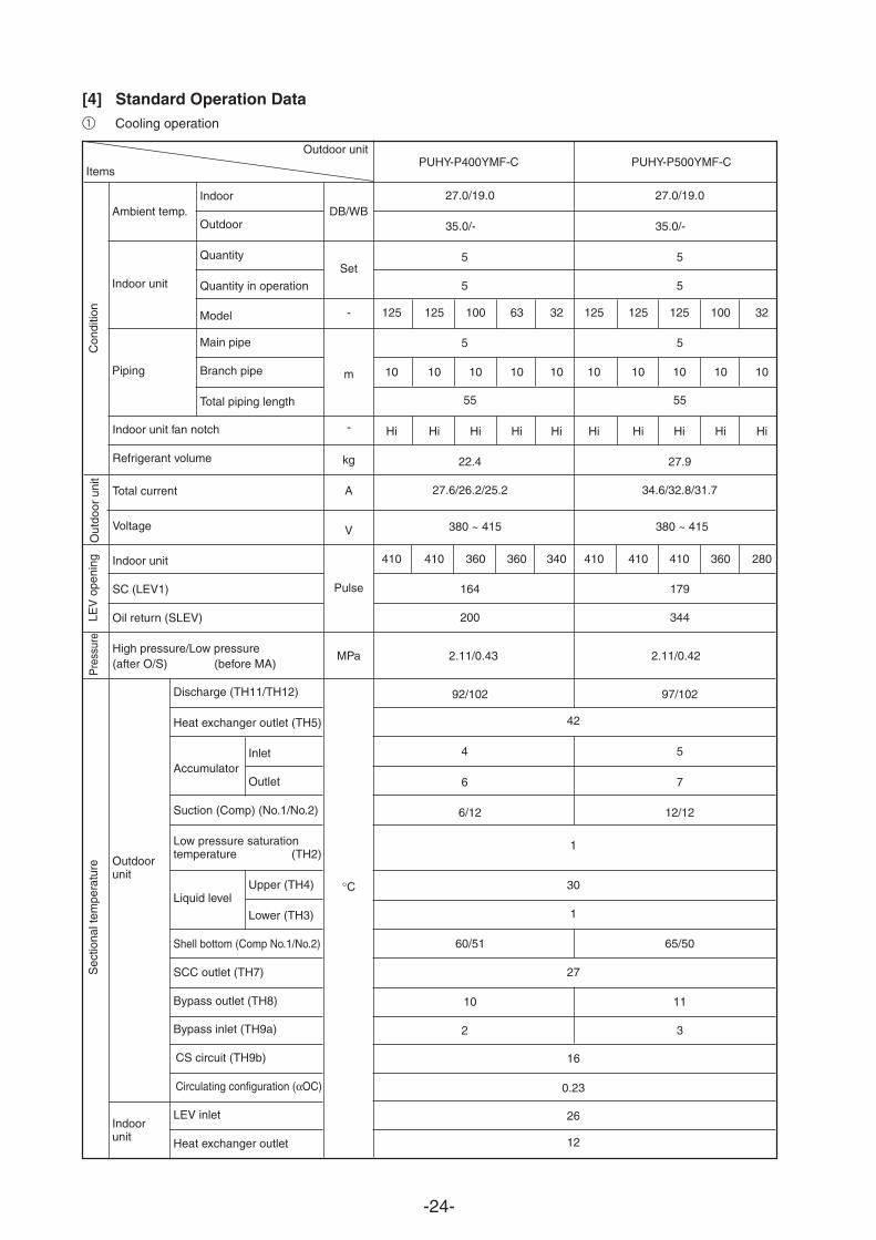
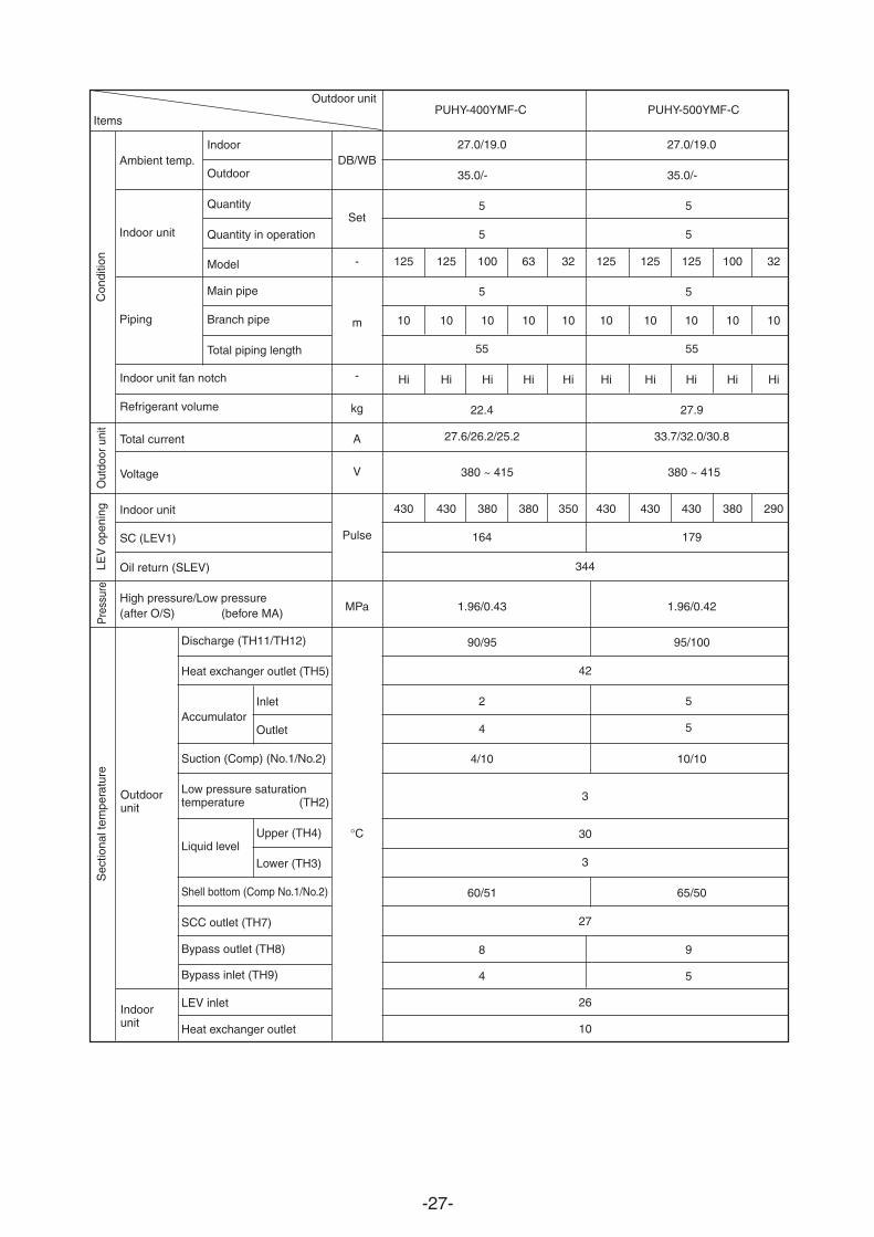
Discharge (TH11/TH12)
Heat exchanger outlet (TH5)
InletAccumulator
Outlet
Suction (Comp) (No.1/No.2)
Low pressure saturationtemperature (TH2)
Upper (TH4)Liquid level
Lower (TH3)
Shell bottom (Comp No.1/No.2)
SCC outlet (TH7)
Bypass outlet (TH8)
Bypass inlet (TH9a)
CS circuit (TH9b)
Circulating configuration (αOC)
LEV inlet
Heat exchanger outlet
27.0/19.0 27.0/19.0
35.0/- 35.0/-
5
5
5
55 55
22.4 27.9
5
5
5
5
7
3
27.6/26.2/25.2 34.6/32.8/31.7
164 179
200 344
2.11/0.43 2.11/0.42
92/102 97/102
42
4
6
6/12 12/12
1
30
1
60/51 65/50
27
10 11
2
16
0.23
26
12
125 125 100 63 32 125 125 125 100 32
10 10 10 10 10 10 10 10 10 10
Hi Hi Hi Hi Hi Hi Hi Hi Hi Hi
410 410 360 360 340 410 410 410 360 280
DB/WB
Set
-
m
-
kg
A
V
Pulse
°C
Outdoorunit
Indoorunit
Outdoor unit
Items
Ambient temp.
Indoor unit
Piping
Con
ditio
n
Indoor
Outdoor
Quantity
Quantity in operation
Model
Main pipe
Branch pipe
Total piping length
Out
door
uni
tS
ectio
nal t
empe
ratu
reP
ress
ure
LEV
ope
ning
Indoor unit fan notch
Refrigerant volume
Total current
Voltage
Indoor unit
SC (LEV1)
Oil return (SLEV)
High pressure/Low pressure(after O/S) (before MA)
380 ~ 415 380 ~ 415
PUHY-P400YMF-C PUHY-P500YMF-C
[4] Standard Operation Data
1 Cooling operation
MPa
-25-
Discharge (TH11/TH12)
Heat exchanger outlet (TH5)
AccumulatorInlet
Outlet
Suction (Comp)
Low pressure saturationtemperature (TH2)
Liquid levelUpper (TH4)
Lower (TH3)
Shell bottom (Comp)
SCC outlet (TH7)
Bypass outlet (TH8)
Bypass inlet (TH9a)
CS circuit (TH9b)
Circulating configuration (αOC)
Discharge temperature (TH11)
Liquid levelUpper (TH4)
Lower (TH3)
Shell bottom (Comp)
SCC outlet (TH7)
Bypass outlet (TH8)
Bypass inlet (TH9)
LEV inlet
Heat exchanger outlet
Variablecapacity
unit
Constantcapacityunit
Indoor unit
Outdoor unit
Items
Ambient temp.
Indoor unit
Piping
Con
ditio
n
Indoor
Outdoor
Quantity
Quantity in operation
Model
Main pipe
Branch pipe
Total piping length
-
Variablecapacity unit
Constantcapacity unit
DB/WB
Set
-
m
-
kg
A
V
Pulse
MPa
°C
Out
door
unit
Sec
tiona
l tem
pera
ture
Pres
-su
reLE
V o
peni
ng
Indoor unit fan notch
Refrigerant volume
Current
Voltage
Indoor unit
SC (LEV1)
Oil return (SLEV)
SC (LEV1)
Liquid pipe (LEV2)
High pressure/Low pressure(after O/S) (before Main ACC)
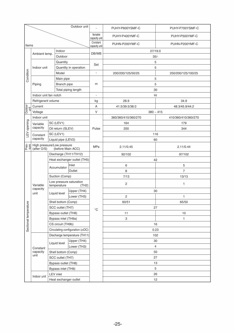
PUHY-P600YSMF-C PUHY-P700YSMF-C
PUHY-P400YMF-C PUHY-P500YMF-C
PUHN-P200YMF-C PUHN-P200YMF-C
27/19.0
35/-
5
5
200/200/125/50/25 250/200/125/100/25
5
5
30
Hi
28.9 34.9
41.5/39.5/38.0 48.3/45.9/44.2
380 ~ 415
360/360/410/360/270 410/360/410/360/270
164 179
5
7
1
1
1
200 344
116
60
2.11/0.45 2.11/0.44
92/102 97/102
42
6
8
7/13 13/13
2
30
2
60/51 65/50
27
11 10
3
16
0.23
102
30
4
50
27
13
5
26
12
Variablecapacity
Constantcapacity

-26-
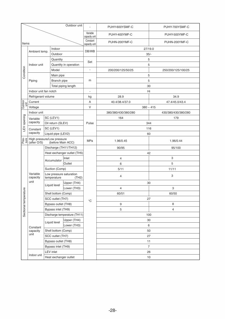
Discharge (TH11/TH12)
Heat exchanger outlet (TH5)
AccumulatorInlet
Outlet
Suction (Comp)
Low pressure saturationtemperature (TH2)
Liquid levelUpper (TH4)
Lower (TH3)
Shell bottom (Comp)
SCC outlet (TH7)
Bypass outlet (TH8)
Bypass inlet (TH9a)
CS circuit (TH9b)
Circulating configuration (αOC)
Discharge temperature (TH11)
Liquid levelUpper (TH4)
Lower (TH3)
Shell bottom (Comp)
SCC outlet (TH7)
Bypass outlet (TH8)
Bypass inlet (TH9)
LEV inlet
Heat exchanger outlet
27/19.0
35/-
5
5
250/200/125/50/25 250/250/125/100/25
5
5
30
Hi
31.9 36.9
44.7/42.5/40.9 51.5/48.9/47.1
380 ~ 415
410/360/410/360/270 410/410/410/360/270
164 179
200 344
116
60
2.11/0.45 2.11/0.44
92/102 97/102
42
6
8
7/13 13/13
5
7
1
1
2
30
2
60/51 65/50
27
11 10
23
16
0.23
102
30
3
50
27
12
4
26
12
Variablecapacity
unit
Constantcapacityunit
Indoor unit
Outdoor unit
Items
Ambient temp.
Indoor unit
Piping
Con
ditio
n
Indoor
Outdoor
Quantity
Quantity in operation
Model
Main pipe
Branch pipe
Total piping length
-
Variablecapacity unit
Constantcapacity unit
DB/WB
Set
-
m
-
kg
A
V
Pulse
MPa
°C
Out
door
unit
Sec
tiona
l tem
pera
ture
Pres
-su
reLE
V o
peni
ng
Indoor unit fan notch
Refrigerant volume
Current
Voltage
Indoor unit
SC (LEV1)
Oil return (SLEV)
SC (LEV1)
Liquid pipe (LEV2)
High pressure/Low pressure(after O/S) (before Main ACC)
PUHY-P650YSMF-C PUHY-P750YSMF-C
PUHY-P400YMF-C PUHY-P500YMF-C
PUHN-P250YMF-C PUHN-P250YMF-C
Variablecapacity
Constantcapacity
-27-
27.0/19.0 27.0/19.0
35.0/- 35.0/-
5
5
5
55 55
5
5
5
9
5
5
5
22.4 27.9
27.6/26.2/25.2 33.7/32.0/30.8
164 179
344
1.96/0.43 1.96/0.42
90/95 95/100
42
2
4
4/10 10/10
3
30
3
60/51 65/50
27
8
4
26
10
DB/WB
Set
-
m
-
kg
A
V
Pulse
MPa
°C
Outdoorunit
Indoorunit
Outdoor unit
Items
Ambient temp.
Indoor unit
Piping
Con
ditio
n
Indoor
Outdoor
Quantity
Quantity in operation
Model
Main pipe
Branch pipe
Total piping length
Discharge (TH11/TH12)
Heat exchanger outlet (TH5)
InletAccumulator
Outlet
Suction (Comp) (No.1/No.2)
Low pressure saturationtemperature (TH2)
Upper (TH4)Liquid level
Lower (TH3)
Shell bottom (Comp No.1/No.2)
SCC outlet (TH7)
Bypass outlet (TH8)
Bypass inlet (TH9)
LEV inlet
Heat exchanger outlet
Out
door
uni
tS
ectio
nal t
empe
ratu
reP
ress
ure
LEV
ope
ning
Indoor unit fan notch
Refrigerant volume
Total current
Voltage
Indoor unit
SC (LEV1)
Oil return (SLEV)
High pressure/Low pressure(after O/S) (before MA)
125 125 100 63 32 125 125 125 100 32
10 10 10 10 10 10 10 10 10 10
Hi Hi Hi Hi Hi Hi Hi Hi Hi Hi
430 430 380 380 350 430 430 430 380 290
380 ~ 415 380 ~ 415
PUHY-400YMF-C PUHY-500YMF-C
-28-
Variablecapacity
unit
Constantcapacityunit
Indoor unit
Outdoor unit
Items
Ambient temp.
Indoor unit
Piping
Con
ditio
n
Indoor
Outdoor
Quantity
Quantity in operation
Model
Main pipe
Branch pipe
Total piping length
Discharge (TH11/TH12)
Heat exchanger outlet (TH5)
AccumulatorInlet
Outlet
Suction (Comp)
Low pressure saturationtemperature (TH2)
Liquid levelUpper (TH4)
Lower (TH3)
Shell bottom (Comp)
SCC outlet (TH7)
Bypass outlet (TH8)
Bypass inlet (TH9)
Discharge temperature (TH11)
Liquid levelUpper (TH4)
Lower (TH3)
Shell bottom (Comp)
SCC outlet (TH7)
Bypass outlet (TH8)
Bypass inlet (TH9)
LEV inlet
Heat exchanger outlet
-
Variablecapacity unit
Constantcapacity unit
DB/WB
Set
-
m
-
kg
A
V
Pulse
°C
Out
door
unit
Sec
tiona
l tem
pera
ture
Pres
-su
reLE
V o
peni
ng
Indoor unit fan notch
Refrigerant volume
Current
Voltage
Indoor unit
SC (LEV1)
Oil return (SLEV)
SC (LEV1)
Liquid pipe (LEV2)
High pressure/Low pressure(after O/S) (before Main ACC)
PUHY-600YSMF-C PUHY-700YSMF-C
PUHY-400YMF-C PUHY-500YMF-C
PUHN-200YMF-C PUHN-200YMF-C
27/19.0
35/-
5
5
200/200/125/50/25 250/200/125/100/25
5
5
30
Hi
28.9 34.9
40.4/38.4/37.0 47.4/45.0/43.4
380 ~ 415
380/380/430/380/280 430/380/430/380/280
164 179
344
116
60
1.96/0.45 1.96/0.44
90/95 95/100
3
5
3
42
4
6
5/11 11/11
4
30
4
60/51 60/50
3
8
4
27
9
5
100
30
6
50
27
11
7
26
10
Variablecapacity
Constantcapacity
MPa

-29-
Variablecapacity
unit
Constantcapacityunit
Indoor unit
Outdoor unit
Items
Ambient temp.
Indoor unit
Piping
Con
ditio
n
Indoor
Outdoor
Quantity
Quantity in operation
Model
Main pipe
Branch pipe
Total piping length
Discharge (TH11/TH12)
Heat exchanger outlet (TH5)
AccumulatorInlet
Outlet
Suction (Comp)
Low pressure saturationtemperature (TH2)
Liquid levelUpper (TH4)
Lower (TH3)
Shell bottom (Comp)
SCC outlet (TH7)
Bypass outlet (TH8)
Bypass inlet (TH9)
Discharge temperature (TH11)
Liquid levelUpper (TH4)
Lower (TH3)
Shell bottom (Comp)
SCC outlet (TH7)
Bypass outlet (TH8)
Bypass inlet (TH9)
LEV inlet
Heat exchanger outlet
-
Variablecapacity unit
Constantcapacity unit
DB/WB
Set
-
m
-
kg
A
V
Pulse
MPa
°C
Out
door
unit
Sec
tiona
l tem
pera
ture
Pres
-su
reLE
V o
peni
ng
Indoor unit fan notch
Refrigerant volume
Current
Voltage
Indoor unit
SC (LEV1)
Oil return (SLEV)
SC (LEV1)
Liquid pipe (LEV2)
High pressure/Low pressure(after O/S) (before Main ACC)
PUHY-650YSMF-C PUHY-750YSMF-C
PUHY-400YMF-C PUHY-500YMF-C
PUHN-250YMF-C PUHN-250YMF-C
27/19.0
35/-
5
5
250/200/125/50/25 250/250/125/100/25
5
5
30
Hi
31.9 36.9
43.6/41.4/39.9 50.5/48.0/46.3
380 ~ 415
430/380/430/380/280 430/430/430/380/280
164 179
344
116
60
1.96/0.45 1.96/0.44
90/95 95/100
3
5
3
3
8
4
42
4
6
5/11 11/11
4
30
4
60/51 65/50
27
9
5
100
30
5
50
27
10
6
26
10
Variablecapacity
Constantcapacity
-30-
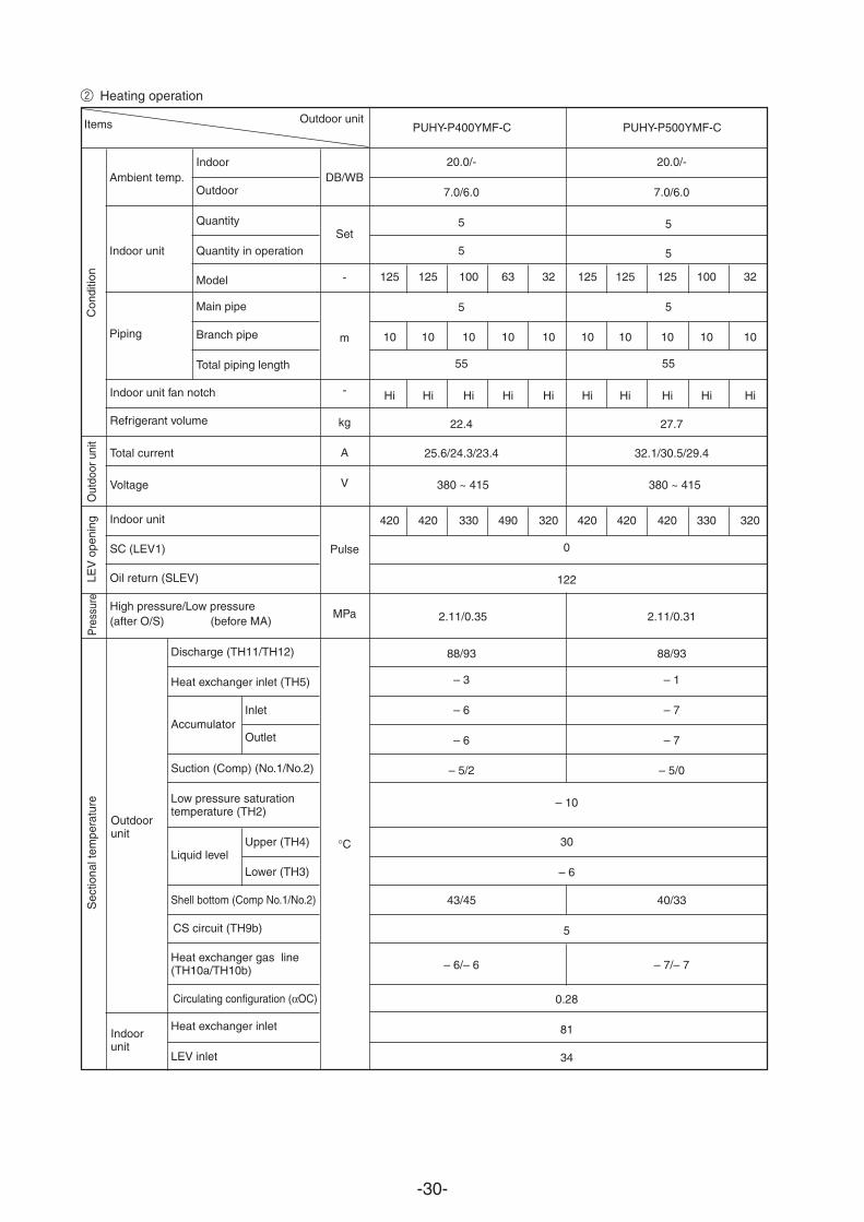
Discharge (TH11/TH12)
Heat exchanger inlet (TH5)
InletAccumulator
Outlet
Suction (Comp) (No.1/No.2)
Low pressure saturationtemperature (TH2)
Upper (TH4)Liquid level
Lower (TH3)
Shell bottom (Comp No.1/No.2)
CS circuit (TH9b)
Heat exchanger gas line(TH10a/TH10b)
Circulating configuration (αOC)
Heat exchanger inlet
LEV inlet
125 125 100 63 32 125 125 125 100 32
10 10 10 10 10 10 10 10 10 10
Hi Hi Hi Hi Hi Hi Hi Hi Hi Hi
420 420 330 490 320 420 420 420 330 320
20.0/- 20.0/-
7.0/6.0 7.0/6.0
5
5
5
55 55
5
5
5
22.4 27.7
25.6/24.3/23.4 32.1/30.5/29.4
0
122
2.11/0.35 2.11/0.31
88/93 88/93
– 3 – 1
– 6 – 7
– 6 – 7
– 5/2 – 5/0
– 10
30
– 6
43/45 40/33
5
– 6/– 6 – 7/– 7
0.28
81
34
DB/WB
Set
-
m
-
kg
A
V
Pulse
MPa
°C
Outdoor unitItems
Ambient temp.
Indoor unit
Piping
Con
ditio
n
Indoor
Outdoor
Quantity
Quantity in operation
Model
Main pipe
Branch pipe
Total piping length
Outdoorunit
Indoorunit
Out
door
uni
tS
ectio
nal t
empe
ratu
reP
ress
ure
LEV
ope
ning
Indoor unit fan notch
Refrigerant volume
Total current
Voltage
Indoor unit
SC (LEV1)
Oil return (SLEV)
High pressure/Low pressure(after O/S) (before MA)
380 ~ 415 380 ~ 415
PUHY-P400YMF-C PUHY-P500YMF-C
2 Heating operation

-31-
Discharge (TH11/TH12)
Heat exchanger outlet (TH5)
AccumulatorInlet
Outlet
Suction (Comp)
Low pressure saturationtemperature (TH2)
Liquid levelUpper (TH4)
Lower (TH3)
Shell bottom (Comp)
CS circuit (TH9b)
Heat exchanger gas line(TH10a/TH10b)
Circulating configuration (αOC)
Discharge temperature (TH11)
Suction (Comp)
Liquid levelUpper (TH4)
Lower (TH3)
Shell bottom (Comp)
Heat exchanger gas line(TH10a)
Heat exchanger inlet
LEV inlet
20/-
7/6
5
5
200/200/125/50/25 250/200/125/100/25
5
5
30
Hi
28.9 34.9
37.0/35.2/33.9 43.9/41.7/40.2
380 ~ 415
330/330/420/430/270 420/330/420/330/270
0
122 198
0
500
2.11/0.34 2.11/0.34
88/93
– 3 – 1
– 5 – 6
– 5 – 6
– 5/2 – 6/0
– 9 – 10
30
– 5 – 6
43/45 40/33
5
– 5/– 5 – 6/– 6
0.28
93
1
30
– 5
33
– 1
81
34
Variablecapacity
unit
Constantcapacityunit
Indoor unit
Outdoor unit
Items
Ambient temp.
Indoor unit
Piping
Con
ditio
n
Indoor
Outdoor
Quantity
Quantity in operation
Model
Main pipe
Branch pipe
Total piping length
-
Variablecapacity unit
Constantcapacity unit
DB/WB
Set
-
m
-
kg
A
V
Pulse
MPa
°C
Out
door
unit
Sec
tiona
l tem
pera
ture
Pres
-su
reLE
V o
peni
ng
Indoor unit fan notch
Refrigerant volume
Current
Voltage
Indoor unit
SC (LEV1)
Oil return (SLEV)
SC (LEV1)
Liquid pipe (LEV2)
High pressure/Low pressure(after O/S) (before Main ACC)
PUHY-P600YSMF-C PUHY-P700YSMF-C
PUHY-P400YMF-C PUHY-P500YMF-C
PUHN-P200YMF-C PUHN-P200YMF-C
Variablecapacity
Constantcapacity
-32-
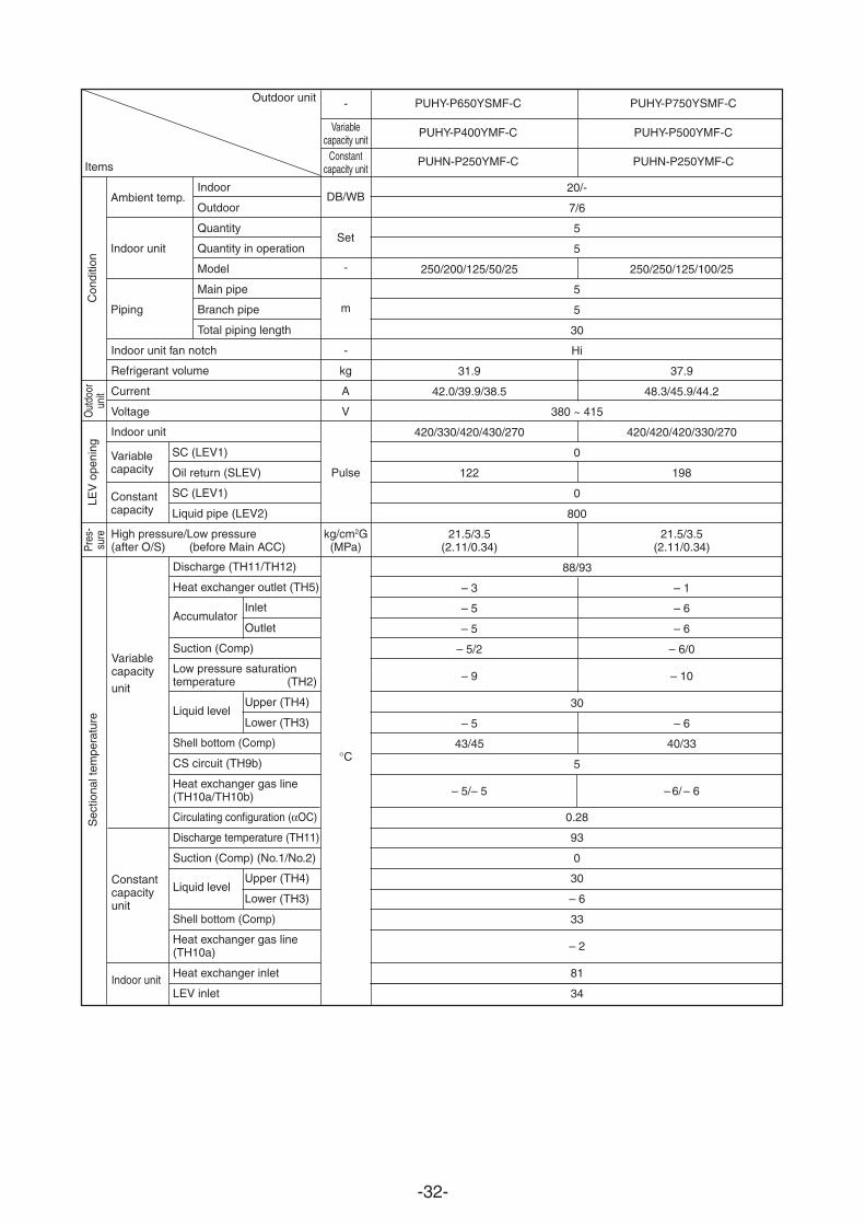
Discharge (TH11/TH12)
Heat exchanger outlet (TH5)
AccumulatorInlet
Outlet
Suction (Comp)
Low pressure saturationtemperature (TH2)
Liquid levelUpper (TH4)
Lower (TH3)
Shell bottom (Comp)
CS circuit (TH9b)
Heat exchanger gas line(TH10a/TH10b)
Circulating configuration (αOC)
Discharge temperature (TH11)
Suction (Comp) (No.1/No.2)
Liquid levelUpper (TH4)
Lower (TH3)
Shell bottom (Comp)
Heat exchanger gas line(TH10a)
Heat exchanger inlet
LEV inlet
Variablecapacity
unit
Constantcapacityunit
Indoor unit
Outdoor unit
Items
Ambient temp.
Indoor unit
Piping
Con
ditio
n
Indoor
Outdoor
Quantity
Quantity in operation
Model
Main pipe
Branch pipe
Total piping length
-
Variablecapacity unit
Constantcapacity unit
DB/WB
Set
-
m
-
kg
A
V
Pulse
kg/cm2G(MPa)
°C
Out
door
unit
Sec
tiona
l tem
pera
ture
Pres
-su
reLE
V o
peni
ng
Indoor unit fan notch
Refrigerant volume
Current
Voltage
Indoor unit
SC (LEV1)
Oil return (SLEV)
SC (LEV1)
Liquid pipe (LEV2)
High pressure/Low pressure(after O/S) (before Main ACC)
PUHY-P650YSMF-C PUHY-P750YSMF-C
PUHY-P400YMF-C PUHY-P500YMF-C
PUHN-P250YMF-C PUHN-P250YMF-C
20/-
7/6
5
5
250/200/125/50/25 250/250/125/100/25
5
5
30
Hi
31.9 37.9
42.0/39.9/38.5 48.3/45.9/44.2
380 ~ 415
420/330/420/430/270 420/420/420/330/270
0
122 198
0
800
21.5/3.5 21.5/3.5(2.11/0.34) (2.11/0.34)
88/93
– 3 – 1
– 5 – 6
– 5 – 6
– 5/2 – 6/0
– 9 – 10
30
– 5 – 6
43/45 40/33
5
– 5/– 5 –
6/ – 6
0.28
93
0
30
– 6
33
– 2
81
34
Variablecapacity
Constantcapacity
-33-
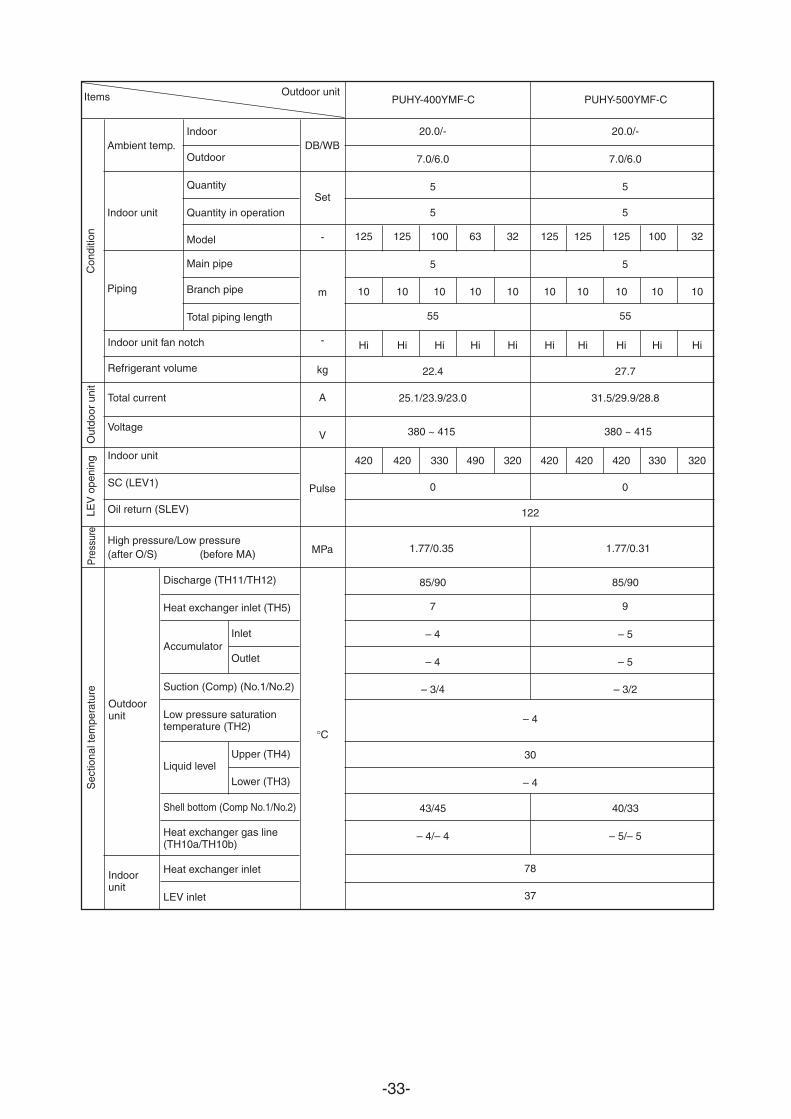
20.0/- 20.0/-
7.0/6.0 7.0/6.0
5
5
5
55 55
22.4 27.7
25.1/23.9/23.0 31.5/29.9/28.8
0
122
1.77/0.35 1.77/0.31
85/90 85/90
7
– 4 – 5
– 4 – 5
– 3/4 – 3/2
– 4
30
– 4
43/45 40/33
9
0
5
5
5
– 4/– 4 – 5/– 5
78
37
125 125 100 63 32 125 125 125 100 32
10 10 10 10 10 10 10 10 10 10
Hi Hi Hi Hi Hi Hi Hi Hi Hi Hi
420 420 330 490 320 420 420 420 330 320
Discharge (TH11/TH12)
Heat exchanger inlet (TH5)
InletAccumulator
Outlet
Suction (Comp) (No.1/No.2)
Low pressure saturationtemperature (TH2)
Upper (TH4)Liquid level
Lower (TH3)
Shell bottom (Comp No.1/No.2)
Heat exchanger gas line(TH10a/TH10b)
Heat exchanger inlet
LEV inlet
DB/WB
Set
-
m
-
kg
A
V
Pulse
MPa
°C
Outdoor unitItems
Ambient temp.
Indoor unit
Piping
Con
ditio
n
Indoor
Outdoor
Quantity
Quantity in operation
Model
Main pipe
Branch pipe
Total piping length
Outdoorunit
Indoorunit
Out
door
uni
tS
ectio
nal t
empe
ratu
reP
ress
ure
LEV
ope
ning
Indoor unit fan notch
Refrigerant volume
Total current
Voltage
Indoor unit
SC (LEV1)
Oil return (SLEV)
High pressure/Low pressure(after O/S) (before MA)
380 ~ 415 380 ~ 415
PUHY-400YMF-C PUHY-500YMF-C
-34-
Variablecapacity
unit
Constantcapacityunit
Indoor unit
Outdoor unit
Items
Ambient temp.
Indoor unit
Piping
Con
ditio
n
Indoor
Outdoor
Quantity
Quantity in operation
Model
Main pipe
Branch pipe
Total piping length
Discharge (TH11/TH12)
Heat exchanger outlet (TH5)
AccumulatorInlet
Outlet
Suction (Comp)
Low pressure saturationtemperature (TH2)
Liquid levelUpper (TH4)
Lower (TH3)
Shell bottom (Comp)
Heat exchanger gas line(TH10a/TH10b)
Discharge temperature (TH11)
Suction (Comp)
Liquid levelUpper (TH4)
Lower (TH3)
Shell bottom (Comp)
Bypass inlet (TH9)
Heat exchanger gas line(TH10a)
Heat exchanger inlet
LEV inlet
-
Variablecapacity unit
Constantcapacity unit
DB/WB
Set
-
m
-
kg
A
V
Pulse
MPa
°C
Out
door
unit
Sec
tiona
l tem
pera
ture
Pres
-su
reLE
V o
peni
ng
Indoor unit fan notch
Refrigerant volume
Current
Voltage
Indoor unit
SC (LEV1)
Oil return (SLEV)
SC (LEV1)
Liquid pipe (LEV2)
High pressure/Low pressure(after O/S) (before Main ACC)
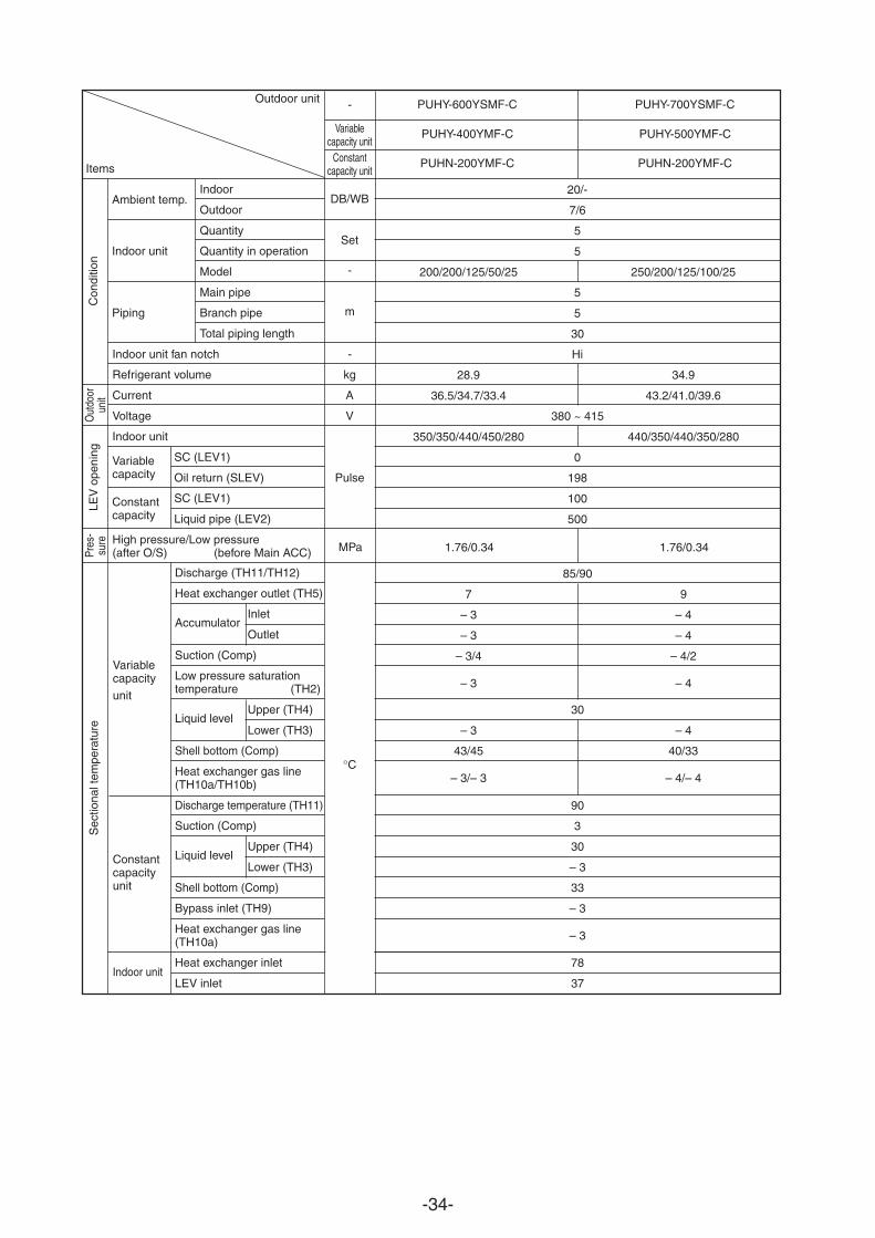
PUHY-600YSMF-C PUHY-700YSMF-C
PUHY-400YMF-C PUHY-500YMF-C
PUHN-200YMF-C PUHN-200YMF-C
20/-
7/6
5
5
200/200/125/50/25 250/200/125/100/25
5
5
30
Hi
28.9 34.9
9
36.5/34.7/33.4 43.2/41.0/39.6
380 ~ 415
350/350/440/450/280 440/350/440/350/280
0
198
100
500
1.76/0.34 1.76/0.34
85/90
7
– 3 – 4
– 3 – 4
– 3/4 – 4/2
– 3 – 4
30
– 3 – 4
43/45 40/33
– 3/– 3 – 4/– 4
90
3
30
– 3
33
– 3
– 3
78
37
Variablecapacity
Constantcapacity
-35-
Variablecapacity
unit
Constantcapacityunit
Indoor unit
Outdoor unit
Items
Ambient temp.
Indoor unit
Piping
Con
ditio
n
Indoor
Outdoor
Quantity
Quantity in operation
Model
Main pipe
Branch pipe
Total piping length
Discharge (TH11/TH12)
Heat exchanger outlet (TH5)
AccumulatorInlet
Outlet
Suction (Comp)
Low pressure saturationtemperature (TH2)
Liquid levelUpper (TH4)
Lower (TH3)
Shell bottom (Comp)
Heat exchanger gas line(TH10a/TH10b)
Discharge temperature (TH11)
Suction (Comp) (No.1/No.2)
Liquid levelUpper (TH4)
Lower (TH3)
Shell bottom (Comp)
Bypass inlet (TH9)
Heat exchanger gas line(TH10a)
Heat exchanger inlet
LEV inlet
-
Variablecapacity unit
Constantcapacity unit
DB/WB
Set
-
m
-
kg
A
V
Pulse
°C
Out
door
unit
Sec
tiona
l tem
pera
ture
Pres
-su
reLE
V o
peni
ng
Indoor unit fan notch
Refrigerant volume
Current
Voltage
Indoor unit
SC (LEV1)
Oil return (SLEV)
SC (LEV1)
Liquid pipe (LEV2)
High pressure/Low pressure(after O/S) (before Main ACC)
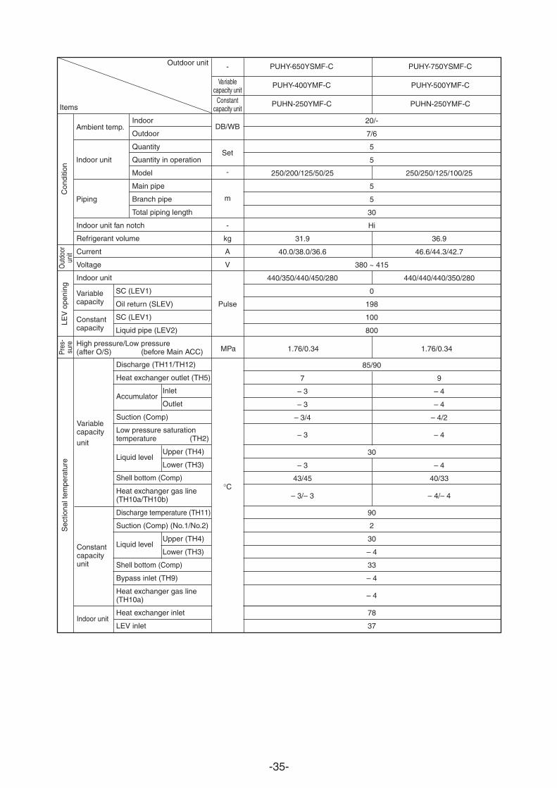
PUHY-650YSMF-C PUHY-750YSMF-C
PUHY-400YMF-C PUHY-500YMF-C
PUHN-250YMF-C PUHN-250YMF-C
20/-
7/6
5
5
250/200/125/50/25 250/250/125/100/25
5
5
30
Hi
31.9 36.9
40.0/38.0/36.6 46.6/44.3/42.7
380 ~ 415
440/350/440/450/280 440/440/440/350/280
0
198
100
800
9
1.76/0.34 1.76/0.34
85/90
7
– 3 – 4
– 3 – 4
– 3/4 – 4/2
– 3 – 4
30
– 3 – 4
43/45 40/33
– 3/– 3 – 4/
– 4
90
2
30
– 4
33
– 4
– 4
78
37
Variablecapacity
Constantcapacity
MPa
-36-
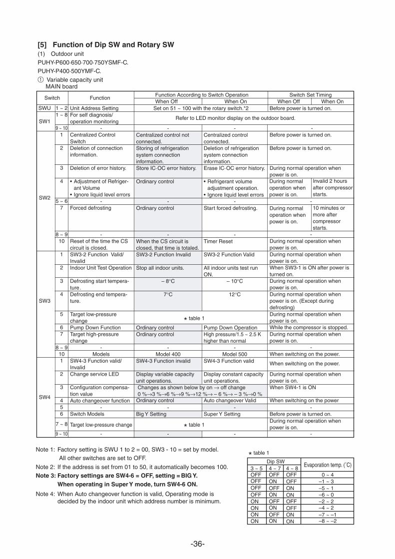
Function According to Switch Operation Switch Set TimingWhen Off When On When Off When On
SWU 1 ~ 2
SW11 ~ 8
8 ~ 9
8 ~ 9
5 ~ 6
Refer to LED monitor displa
* table 1
* table 1
* table 1
y on the outdoor board.
9 ~ 10
9 ~ 10
SW2
1
2
3
4
7
10
SW3
1
2
3
4
5
67
10
SW4
1
2
3
456
-Centralized control notconnected.Storing of refrigerationsystem connectioninformation.Store IC·OC error history.
Ordinary control
-Ordinary control
-When the CS circuit isclosed, that time is totaled.SW3-2 Function Invalid
Stop all indoor units.
– 8°C
7°C
Ordinary controlOrdinary control
-Model 400
SW4-3 Function invalid
Display variable capacityunit operations.
Big Y Setting
-
[5] Function of Dip SW and Rotary SW(1) Outdoor unitPUHY-P600·650·700·750YSMF-C.PUHY-P400·500YMF-C.
MAIN board
-Centralized controlconnected.Deletion of refrigerationsystem connectioninformation.Erase IC·OC error history.
• Refrigerant volumeadjustment operation.
• Ignore liquid level errors-
Start forced defrosting.
-Timer Reset
SW3-2 Function Valid
All indoor units test runON.
– 10°C
12°C
Pump Down OperationHigh pressure/1.5 ~ 2.5 Khigher than normal
-Model 500
SW4-3 Function valid
Display constant capacityunit operations.
Super Y Setting
-
Changes as shown below by on → off change0 %→3 %→6 %→9 %→12 %→ – 6 %→ – 3 %→0 %
Unit Address SettingFor self diagnosis/operation monitoring
-Centralized ControlSwitchDeletion of connectioninformation.
Deletion of error history.
• Adjustment of Refriger-ant Volume
• Ignore liquid level errors-
Forced defrosting
-Reset of the time the CScircuit is closed.SW3-2 Function Valid/InvalidIndoor Unit Test Operation
Defrosting start tempera-ture .Defrosting end tempera-ture.
Target low-pressurechangePump Down FunctionTarget high-pressurechange
-Models
SW4-3 Function valid/InvalidChange service LED
Configuration compensa-tion Auto changeover function
value
Switch
Target low-pressure change
Models-
-
Switch Function
During normaloperation whenpower is on.
Invalid 2 hoursafter compressorstarts.
Before power is turned on.
-Before power is turned on.
Before power is turned on.
During normal operation whenpower is on.
-
-During normal operation whenpower is on.During normal operation whenpower is on.When SW3-1 is ON after power isturned on.During normal operation whenpower is on.During normal operation whenpower is on. (Except duringdefrosting)During normal operation whenpower is on.While the compressor is stopped.During normal operation whenpower is on.
-When switching on the power.
When switching on the power.
During normal operation whenpower is on.
During normal operation whenpower is on.
When SW4-1 is ON
- - -Bef
Ordinary control Auto changeover Valid When switching on the power
ore power is turned on.-
-
During normaloperation whenpower is on.
10 minutes ormore aftercompressorstarts.
Set on 51 ~ 100 with the rotary switch.*2
Note 1: Factory setting is SWU 1 to 2 = 00, SW3 - 10 = set by model.
Note 2: If the address is set from 01 to 50, it automatically becomes 100.
Note 4: When Auto changeover function is valid, Operating mode is decided by the indoor unit which address number is minimum.
Note 3: Factory settings are SW4-6 = OFF, setting = BIG Y.When operating in Super Y mode, turn SW4-6 ON.
All other switches are set to OFF.
1 Variable capacity unit
7 ~ 8
Evaporation temp. (˚C)Dip SW
0 ~ 43 ~ 5 4 ~ 7 4 ~ 8OFFOFFOFFOFF
OFF OFF
ONOFF ONON
ONONONON
OFF OFFONOFF ON
OFF
ON
OFF
ON
ON –1 ~ 3–5 ~ 1–6 ~ 0–2 ~ 2–4 ~ 2–7 ~ –1–8 ~ –2
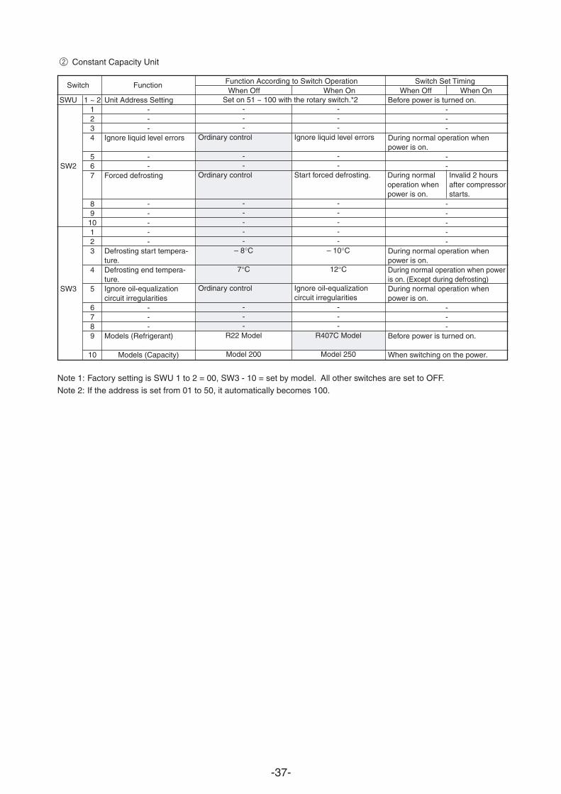
-37-
Function According to Switch Operation Switch Set TimingWhen Off When On When Off When On
SWU 1 ~ 2
SW2
1234
567
89
10
SW3
123
4
5
6789
10
Note 1: Factory setting is SWU 1 to 2 = 00, SW3 - 10 = set by model. All other switches are set to OFF.
Note 2: If the address is set from 01 to 50, it automatically becomes 100.
---
Ignore liquid level errors
--
Start forced defrosting.
-----
– 10°C
12°C
Ignore oil-equalizationcircuit irregularities
---
R407C Model
Model 250
---
Ordinary control
--
Ordinary control
-----
– 8°C
7°C
Ordinary control
---
R22 Model
Model 200
Before power is turned on.---
During normal operation whenpower is on.
--
-----
During normal operation whenpower is on.During normal operation when poweris on. (Except during defrosting)During normal operation whenpower is on.
---
Before power is turned on.
When switching on the power.
Unit Address Setting---
Ignore liquid level errors
--
Forced defrosting
-----
Defrosting start tempera-ture.Defrosting end tempera-ture.Ignore oil-equalizationcircuit irregularities
---
Models (Refrigerant)
Models (Capacity)
Switch Function
Set on 51 ~ 100 with the rotary switch.*2
During normaloperation whenpower is on.
Invalid 2 hoursafter compressorstarts.
2 Constant Capacity Unit
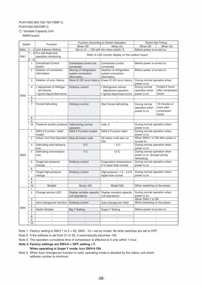
-38-
-Centralized control notconnected.Storing of refrigerationsystem connectioninformation.Store IC·OC error history.
Ordinary control
--
Ordinary control
--
Valid during normaloperationSW3-2 Function Invalid
Stop all indoor units.
0°C
7°C
Ordinary control
Ordinary control
--
Model 400-
Display variable capacityunit operations.
-
Big Y Setting----
When Off When On When Off When OnSWU 1 ~ 2
SW11 ~ 8
Refer to LED monitor display on the outdoor board.
9 ~ 10
SW2
1
2
3
4
567
8910
SW3
1
2
3
4
5
67
8910
SW4
12
345678910
-Centralized controlconnected.Deletion of refrigerationsystem connectioninformation.Erase IC·OC error history.
• Refrigerant volumeadjustment operation.
• Ignore liquid level errors--
Start forced defrosting.
--
note: 3
SW3-2 Function Valid
All indoor units test runON.
– 2°C
12°C
Evaporation temperature /2°C lower than normal
-High pressure / 1.5 ~ 2.5 Khigher than normal
--
Model 500-
Display constant capacityunit operations.
-
Super Y Setting----
Unit Address SettingFor self diagnosis/operation monitoring
-Centralized ControlSwitchDeletion of connectioninformation.
Deletion of error history.
• Adjustment of Refriger-ant Volume
• Ignore liquid level errors--
Forced defrosting
--
Preserve suction pressure
SW3-2 Function Valid/InvalidIndoor Unit Test Operation
Defrosting start tempera-ture.Defrosting end tempera-ture.
Target low-pressurechange
-Target high-pressurechange
--
Models-
Change service LED
-
Switch Models----
Switch Function
During normaloperation whenpower is on.
Invalid 2 hoursafter compressorstarts.
PUHY-600·650·700·750 YSMF-C.PUHY-400·500YMF-C.1 Variable Capacity Unit
MAIN board
Function According to Switch Operation Switch Set Timing
Before power is turned on.
-Before power is turned on.
Before power is turned on.
During normal operation whenpower is on.
--
--
During normal operation whenpower is on.During normal operation whenpower is on.When SW3-1 is ON after power isturned on.During normal operation whenpower is on.During normal operation whenpower is on. (Except duringdefrosting)During normal operation whenpower is on.
-During normal operation whenpower is on.
--
When switching on the power.-
During nor
Ordinary control Auto changeover ValidAuto changeover function When switching on the power.
mal operation whenpower is on.When SW4-1 is ON
- -- -Before power is turned on.
----
During normaloperation whenpower is on.
10 minutes ormore aftercompressorstarts.
Set on 51 ~ 100 with the rotary switch.*2
Note 1: Factory setting is SWU 1 to 2 = 00, SW3 - 10 = set by model. All other switches are set to OFF.Note 2: If the address is set from 01 to 50, it automatically becomes 100.
Note 3: The oper
Note 5: When Auto changeover function is valid, operating mode is decided by the indoor unit which address number is minimum.
ation cumulative time of compressor is effective to it only within 1 hour.Note 4: Factory settings are SW4-6 = OFF, setting = Y.
When operating in Super Y mode, turn SW4-6 ON.
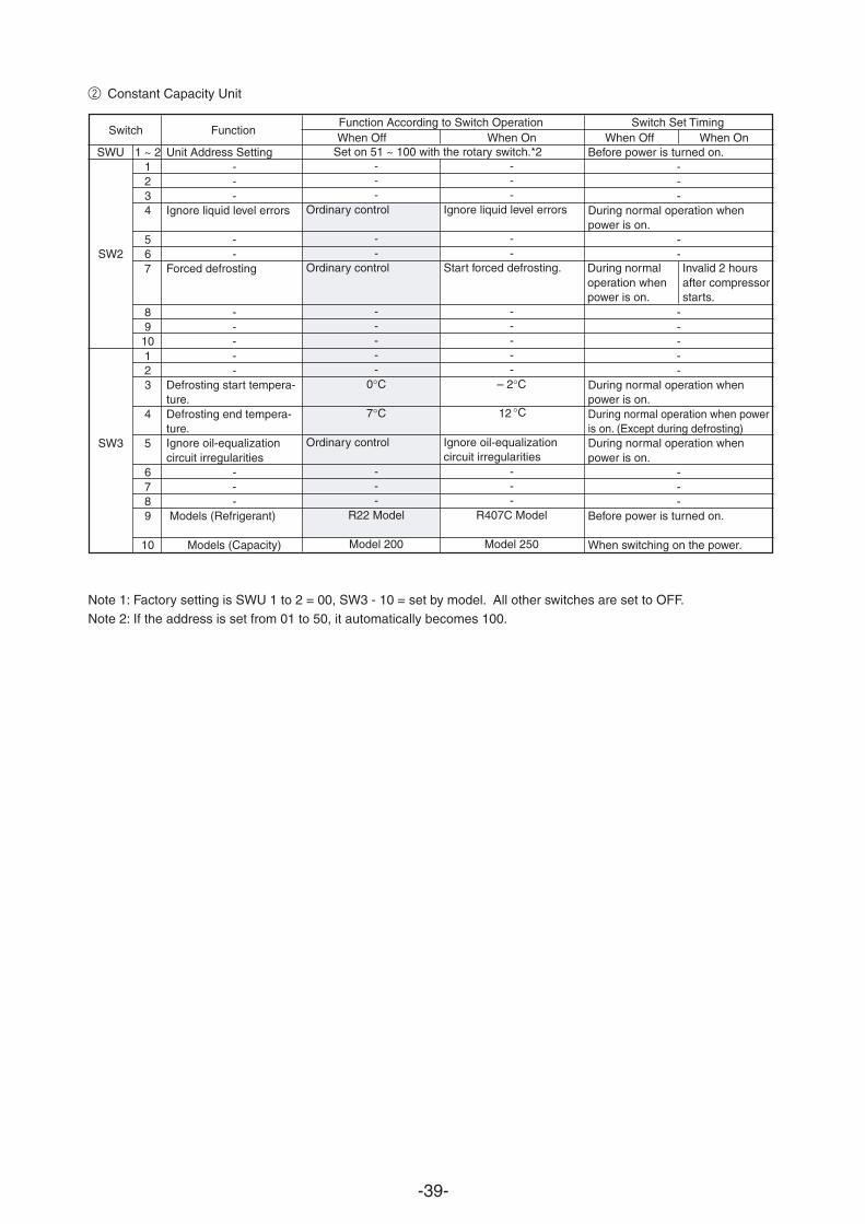
-39-
Function According to Switch Operation Switch Set TimingWhen Off When On When Off When On
SWU 1 ~ 2
SW2
1234
567
89
10
SW3
123
4
5
6789
10
Note 1: Factory setting is SWU 1 to 2 = 00, SW3 - 10 = set by model. All other switches are set to OFF.Note 2: If the address is set from 01 to 50, it automatically becomes 100.
---
Ordinary control
--
Ordinary control
-----
0°C
7°C
Ordinary control
---
R22 Model
Model 200
Before power is turned on.---
During normal operation whenpower is on.
--
-----
During normal operation whenpower is on.During normal operation when poweris on. (Except during defrosting)During normal operation whenpower is on.
---
Before power is turned on.
When switching on the power.
---
Ignore liquid level errors
--
Start forced defrosting.
-----
– 2°C
12
Ignore oil-equalizationcircuit irregularities
---
R407C Model
Model 250
Unit Address Setting---
Ignore liquid level errors
--
Forced defrosting
-----
Defrosting start tempera-ture.Defrosting end tempera-ture.Ignore oil-equalizationcircuit irregularities
---
Models (Refrigerant)
Models (Capacity)
Switch Function
Set on 51 ~ 100 with the rotary switch.*2
During normaloperation whenpower is on.
Invalid 2 hoursafter compressorstarts.
2 Constant Capacity Unit
°C
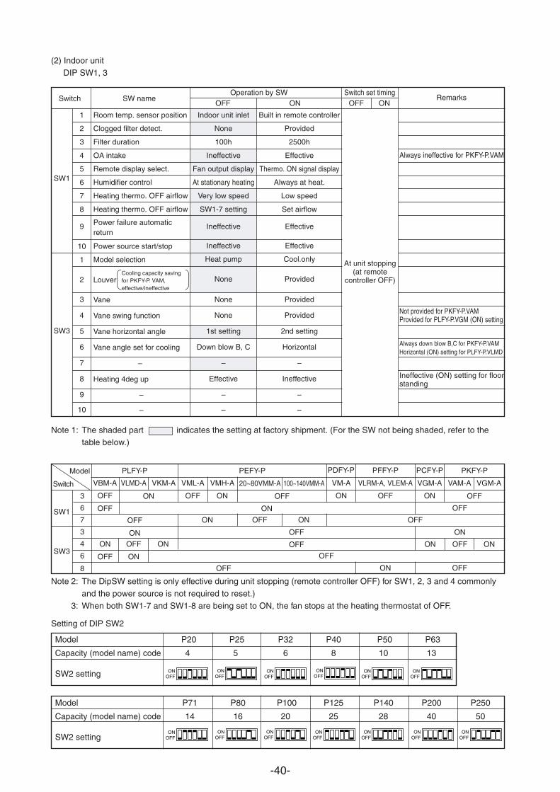
-40-
(2) Indoor unit
DIP SW1, 3
Model P71 P80 P100 P125 P140 P200 P250
Capacity (model name) code 14 16 20 25 28 40 50
SW2 setting
Model P20 P25 P32 P40 P50 P63
Capacity (model name) code 4 5 6 8 10 13
SW2 setting ONOFF
ONOFF
ONOFF
ONOFF
ONOFF
ONOFF
ONOFF
ONOFF
ONOFF
ONOFF
ONOFF
ONOFF
ONOFF
Note 1: The shaded part indicates the setting at factory shipment. (For the SW not being shaded, refer to the
table below.)
Note 2: The DipSW setting is only effective during unit stopping (remote controller OFF) for SW1, 2, 3 and 4 commonly
and the power source is not required to reset.)
3: When both SW1-7 and SW1-8 are being set to ON, the fan stops at the heating thermostat of OFF.
Setting of DIP SW2
Model
Switch
SW1
SW3
3
6
7
3
4
6
8
PLFY-P
VBM-A
OFF
OFF
VLMD-A VKM-A
OFF
ON
ON
ON
OFF
OFF
ON
ON
PEFY-P
VML-A VMH-A 20~80VMM-A 100~140VMM-A
OFFOFF ON
OFF ON
ON
ON
OFF
OFF
OFF
OFF ON OFF
ON OFF ON
ON
OFF
PDFY-P PFFY-P PCFY-P PKFY-P
VM-A
ON
VLRM-A, VLEM-A
OFF
VGM-A
ON
VAM-A VGM-A
OFF
OFF
Indoor unit inlet
None
100h
Ineffective
Fan output display
At stationary heating
Very low speed
SW1-7 setting
Ineffective
Ineffective
Heat pump
None
None
None
1st setting
Down blow B, C
–
Effective
–
–
Built in remote controller
Provided
2500h
Effective
Thermo. ON signal display
Always at heat.
Low speed
Set airflow
Effective
Effective
Cool.only
Provided
Provided
Provided
2nd setting
Horizontal
–
Ineffective
–
–
Room temp. sensor position
Clogged filter detect.
Filter duration
OA intake
Remote display select.
Humidifier control
Heating thermo. OFF airflow
Heating thermo. OFF airflow
Power failure automaticreturn
Power source start/stop
Model selection
Louver
Vane
Vane swing function
Vane horizontal angle
Vane angle set for cooling
–
Heating 4deg up
–
–
Always ineffective for PKFY-P.VAM
Not provided for PKFY-P.VAMProvided for PLFY-P.VGM (ON) setting
Always down blow B,C for PKFY-P.VAMHorizontal (ON) setting for PLFY-P.VLMD
Ineffective (ON) setting for floorstanding
SW1
SW3
1
2
3
4
5
6
7
8
9
10
1
2
3
4
5
6
7
8
9
10
Switch SW nameOperation by SW Switch set timing
OFF ON OFF ONRemarks
At unit stopping(at remote
controller OFF)Cooling capacity savingfor PKFY-P. VAM,effective/ineffective
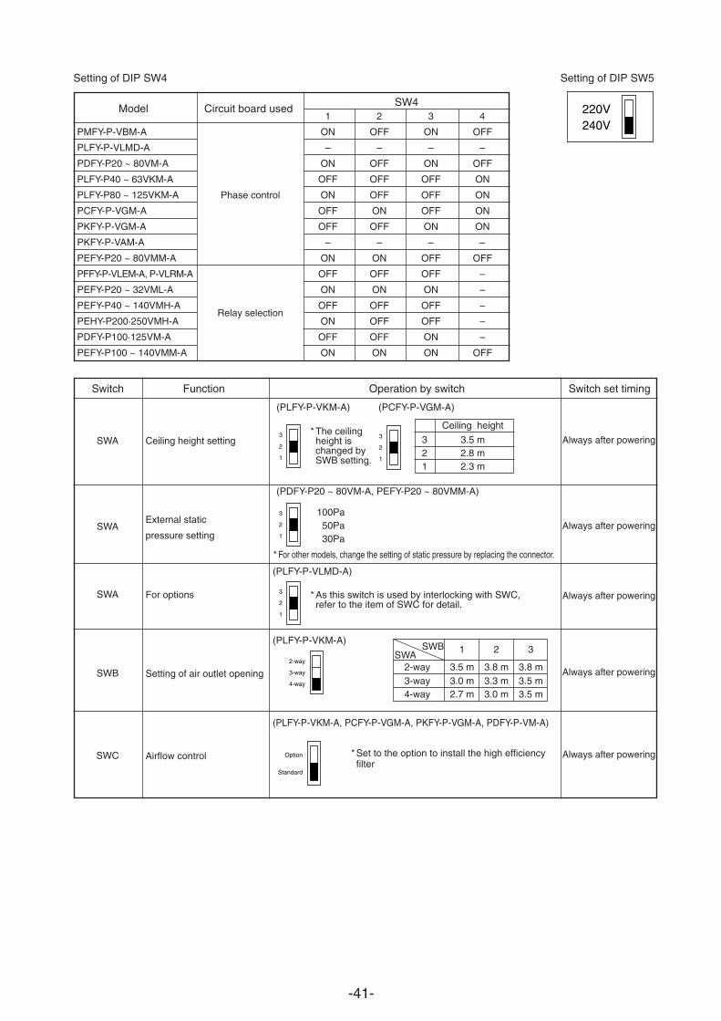
-41-
Ceiling height
3 3.5 m2 2.8 m1 2.3 m
Setting of DIP SW4 Setting of DIP SW5
1 2 3 4
ON OFF ON OFF
– – – –
ON OFF ON OFF
OFF OFF OFF ON
ON OFF OFF ON
OFF ON OFF ON
OFF OFF ON ON
– – – –
ON ON OFF OFF
OFF OFF OFF –
ON ON ON –
OFF OFF OFF –
ON OFF OFF –
OFF OFF ON –
ON ON ON OFF
PMFY-P-VBM-A
PLFY-P-VLMD-A
PDFY-P20 ~ 80VM-A
PLFY-P40 ~ 63VKM-A
PLFY-P80 ~ 125VKM-A
PCFY-P-VGM-A
PKFY-P-VGM-A
PKFY-P-VAM-A
PEFY-P20 ~ 80VMM-A
PFFY-P-VLEM-A, P-VLRM-A
PEFY-P20 ~ 32VML-A
PEFY-P40 ~ 140VMH-A
PEHY-P200·250VMH-A
PDFY-P100·125VM-A
PEFY-P100 ~ 140VMM-A
Model Circuit board usedSW4
Switch Function Operation by switch Switch set timing
SWA
SWA
SWA
SWB
SWC
Ceiling height setting
External static
pressure setting
For options
Setting of air outlet opening
Airflow control
(PLFY-P-VKM-A) (PCFY-P-VGM-A)
(PLFY-P-VLMD-A)
(PLFY-P-VKM-A)
(PLFY-P-VKM-A, PCFY-P-VGM-A, PKFY-P-VGM-A, PDFY-P-VM-A)
Phase control
Relay selection
* The ceilingheight ischanged bySWB setting.
* As this switch is used by interlocking with SWC,refer to the item of SWC for detail.
SWASWB 1 2 3
2-way 3.5 m 3.8 m 3.8 m3-way 3.0 m 3.3 m 3.5 m4-way 2.7 m 3.0 m 3.5 m
* Set to the option to install the high efficiencyfilter
Always after powering
Always after powering
Always after powering
Always after powering
Always after powering
3
1
2
2-way
4-way
3-way
3
1
2
3
1
2
3
1
2
220V240V
Option
Standard
(PDFY-P20 ~ 80VM-A, PEFY-P20 ~ 80VMM-A)
100Pa50Pa30Pa
* For other models, change the setting of static pressure by replacing the connector.
-42-
£ TEST RUN
[1] Before Test Run(1) Check points before test run
1 There should be neither refrigerant leak nor loose power source or transmission lines.
2 Confirm that the resistance between the power source terminal block and the ground exceeds 2MΩ by measur-
ing it with a DC 500 V megger. Do not run if it is lower than 2MΩ.Note: Never apply the megger to the MAIN board. If applied, the MAIN board will be broken.
3 Confirm that the Ball valve at gas and liquid, oil balance sides are fully opened.
Note: Close the cap, after opening the valve.4 Be sure that the crankcase heater has been powered by turning the main power source on at least 12 hours
before starting the test run.
5 If any of the power supply wires (L1, L2, L3, N, .) are mistakenly connected, it is possible to damage the unit.Please exercise caution.
6 A transmission booster (RP) is required when the number of connected indoor unit models in a cooling system
exceeds the number of models specified in the chart below.Note: The maximum number of units that can be controlled is determined by the indoor unit model, the type of
remote controller and their capabilities.
The number of indoor units and the total number of remote controllers is displayed within the parenthesis ( ).
(*1) If even one unit that is higher than 200 exists in the cooling system, the maximum capacity will be “200 or
higher”.
* Please refer to the installation manual for more details.
* Before turning power on to the outdoor unit, first turn on the transmission booster. (If the outdoor unit are mistakenly
turned on first, turn on the transmission booster and then reset the outdoor unit power.)
(2) Caution at inverter check
Because the inverter power portion in outdoor unit electrical part box have a lot of high voltage portions, be sure to follow
the instructions shown below.
During energizing power source, never touch inverter power portion because high voltage (approx. 580 V) isapplied to inverter power portion.
When checking,
Shut off main power source, and check it with tester, etc.
Allow 10 minutes after shutting off main power source.
Open the MAIN board mounting panel, and check whether voltage of both ends of electrolytic capacitor is 20 V or less.
1
2
1
2
3
200 or lower
200 or higher
Remote controller PAR-F 25MA
Prior to Ver. E After Ver. F
16 (32) 20 (40)
16 (32) 16 (32)
(*1)Capability of theconnected indoor units
Remote controller type
Number of connected indoor units thatcan be connected without a RP.
Shorter powering time causes compressor trouble.
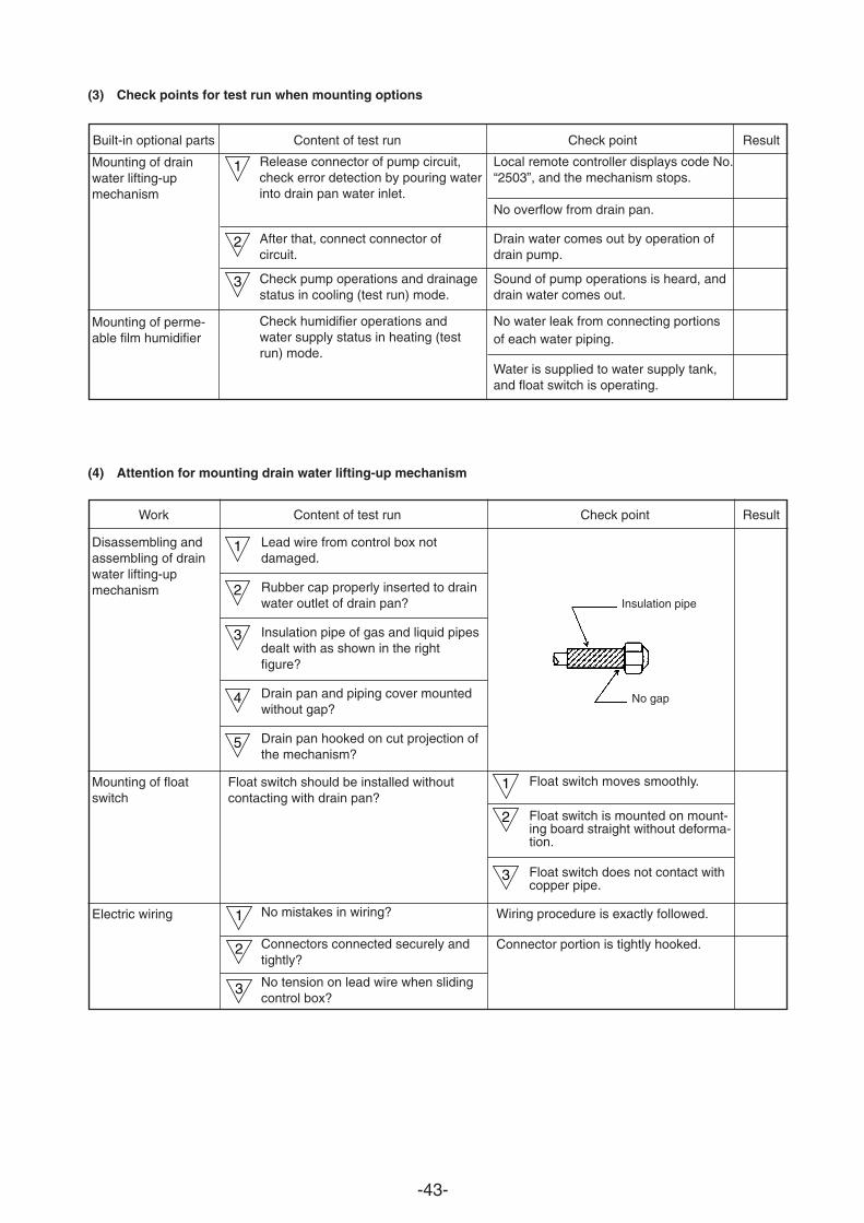
-43-
(3) Check points for test run when mounting options
(4) Attention for mounting drain water lifting-up mechanism
Built-in optional parts Content of test run Check point Result
Mounting of drainwater lifting-upmechanism
Mounting of perme-able film humidifier
Release connector of pump circuit,check error detection by pouring waterinto drain pan water inlet.
After that, connect connector ofcircuit.
Check pump operations and drainagestatus in cooling (test run) mode.
Check humidifier operations andwater supply status in heating (testrun) mode.
Local remote controller displays code No.“2503”, and the mechanism stops.
No overflow from drain pan.
Drain water comes out by operation ofdrain pump.
Sound of pump operations is heard, anddrain water comes out.
No water leak from connecting portionsof each water piping.
Water is supplied to water supply tank,and float switch is operating.
Work Content of test run Check point Result
Disassembling andassembling of drainwater lifting-upmechanism
Mounting of floatswitch
Electric wiring
Lead wire from control box notdamaged.
Rubber cap properly inserted to drainwater outlet of drain pan?
Insulation pipe of gas and liquid pipesdealt with as shown in the rightfigure?
Drain pan and piping cover mountedwithout gap?
Drain pan hooked on cut projection ofthe mechanism?
No mistakes in wiring?
Connectors connected securely andtightly?
No tension on lead wire when slidingcontrol box?
Float switch moves smoothly.
Float switch is mounted on mount-ing board straight without deforma-tion.
Float switch does not contact withcopper pipe.
Wiring procedure is exactly followed.
Connector portion is tightly hooked.
1
2
3
1
2
3
4
5
1
2
3
1
2
3
No gap
Insulation pipe
Float switch should be installed without contacting with drain pan?
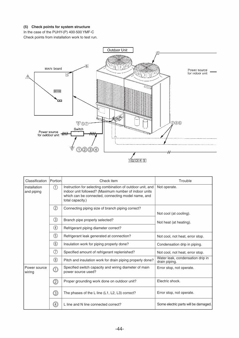
-44-
(5) Check points for system structureIn the case of the PUHY-(P) 400·500 YMF-CCheck points from installation work to test run.
Classification Portion Check item Trouble
Installationand piping
Power sourcewiring
1
2
Instruction for selecting combination of outdoor unit, andindoor unit followed? (Maximum number of indoor unitswhich can be connected, connecting model name, andtotal capacity.)
Specified switch capacity and wiring diameter of mainpower source used?
Proper grounding work done on outdoor unit?
The phases of the L line (L1, L2, L3) correct?
L line and N line connected correct?
Not operate.
Not cool (at cooling).
Not heat (at heating).
Not cool, not heat, error stop.
Condensation drip in piping.
Not cool, not heat, error stop.
Water leak, condensation drip indrain piping.
Error stop, not operate.
Electric shock.
Error stop, not operate.
Some electric parts will be damaged.
1 2 3 4
3
4
5
6
7
8
1
2
3
4
Branch pipe properly selected?
Refrigerant piping diameter correct?
Refrigerant leak generated at connection?
Insulation work for piping properly done?
Specified amount of refrigerant replenished?
Pitch and insulation work for drain piping properly done?
Connecting piping size of branch piping correct?
57 246
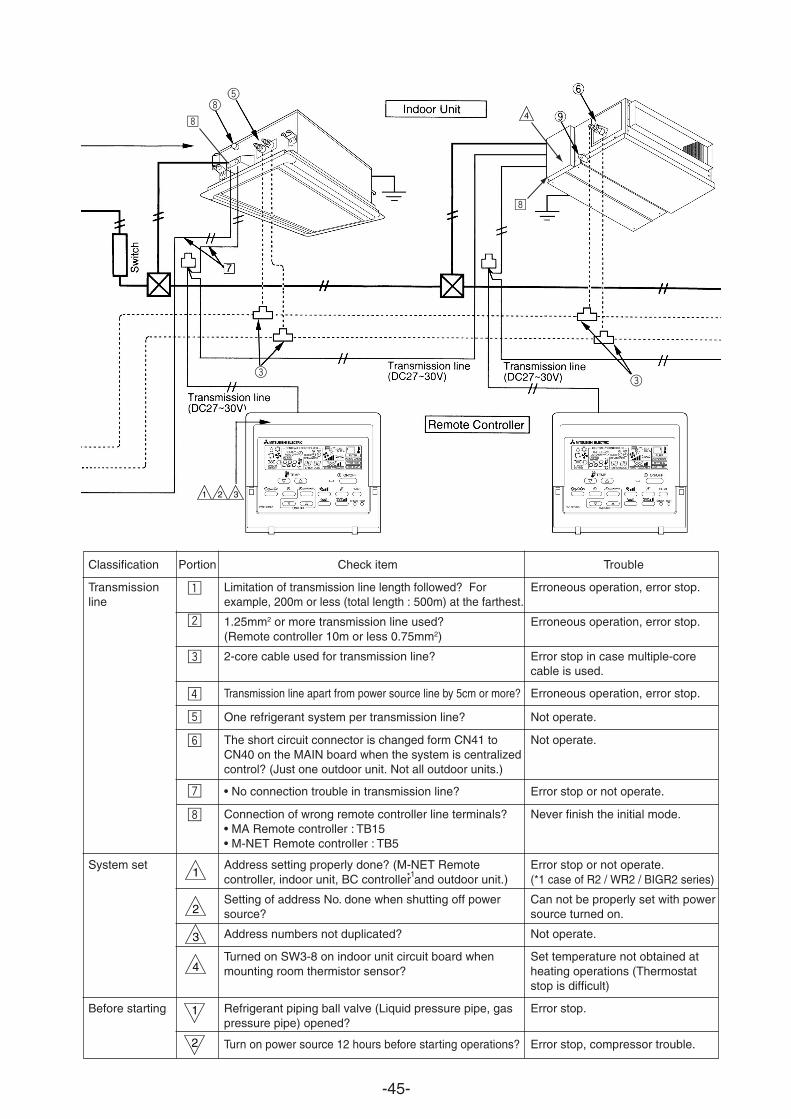
-45-
Classification
Transmissionline
Portion Check item
Limitation of transmission line length followed? Forexample, 200m or less (total length : 500m) at the farthest.
™ 1.25mm2 or more transmission line used?(Remote controller 10m or less 0.75mm2)
2-core cable used for transmission line?
Transmission line apart from power source line by 5cm or more?
One refrigerant system per transmission line?
The short circuit connector is changed form CN41 toCN40 on the MAIN board when the system is centralizedcontrol? (Just one outdoor unit. Not all outdoor units.)
• No connection trouble in transmission line?
Connection of wrong remote controller line terminals?• MA Remote controller : TB15• M-NET Remote controller : TB5
Trouble
Erroneous operation, error stop.
Erroneous operation, error stop.
Error stop in case multiple-corecable is used.
Erroneous operation, error stop.
Not operate.
Not operate.
Error stop or not operate.
Never finish the initial mode.
System set
Before starting
Error stop or not operate.(*1 case of R2 / WR2 / BIGR2 series)
Can not be properly set with powersource turned on.
Not operate.
Set temperature not obtained atheating operations (Thermostatstop is difficult)
Error stop.
Error stop, compressor trouble.
1
2
1
2
3
4
Address setting properly done? (M-NET Remotecontroller, indoor unit, BC controller and outdoor unit.)
Setting of address No. done when shutting off powersource?
Address numbers not duplicated?
Turned on SW3-8 on indoor unit circuit board whenmounting room thermistor sensor?
Refrigerant piping ball valve (Liquid pressure pipe, gaspressure pipe) opened?
Turn on power source 12 hours before starting operations?
*1
5
33
8
•
•
¡
£
¢
∞
§
¶
•
4
1 2 3

-46-
Powersource
foroutdoor
unit
Switch
Switch
MAIN board
Outdoor unit
2
1
1
6
1 2 3 4 5
1
12
In the case of the PUHY-(P) 600·650·700·750 YSMF-CCheck points from installation work to test run.
Classification Portion Check item Trouble
Installationand piping
Power sourcewiring
1
2
3
4
5
6
7
8
1
2
3
4
Instruction for selecting combination of outdoor unit, andindoor unit followed? (Maximum number of indoor unitswhich can be connected, connecting model name, andtotal capacity.)
Follow limitation of refrigerant piping length? For ex-ample, 100 m or less (total length: 220 m) at the farthest.
Branch pipe properly selected?
Refrigerant piping diameter correct?
Refrigerant leak generated at connection?
Insulation work for piping properly done?
Specified amount of refrigerant replenished?
Pitch and insulation work for drain piping properly done?
Specified switch capacity and wiring diameter of mainpower source used?
Proper grounding work done on outdoor unit?
Not operate.
Not cool (at cooling).
Not heat (at heating).
Not cool, not heat, error stop
.Condensation drip in piping.
Not cool, not heat, error stop.
Water leak, condensation drip indrain piping.
Error stop, not operate.
Error stop, not operate.
L line and N line connected correct? Some electric parts will be dameged.
* Limitations apply when 17 or more indoor units are connected. Please refer to the installation manual.
34
462
57
The phase of the L line (L1,L2,L3) is correct.
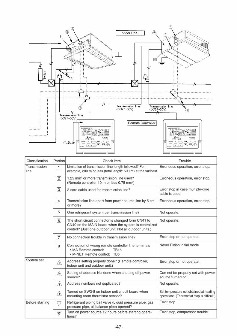
-47-
Classification Portion Check item
Transmissionline
System set
Before starting
Limitation of transmission line length followed? Forexample, 200 m or less (total length: 500 m) at the farthest.
1.25 mm2 or more transmission line used?(Remote controller 10 m or less 0.75 mm2)
2-core cable used for transmission line?
Transmission line apart from power source line by 5 cmor more?
One refrigerant system per transmission line?
The short circuit connector is changed form CN41 toCN40 on the MAIN board when the system is centralizedcontrol? (Just one outdoor unit. Not all outdoor units.)
No connection trouble in transmission line?
Address setting properly done? (Remote controller,indoor unit and outdoor unit.)
Setting of address No. done when shutting off powersource?
Address numbers not duplicated?
Turned on SW3-8 on indoor unit circuit board whenmounting room thermistor sensor?
Refrigerant piping ball valve (Liquid pressure pipe, gaspressure pipe, oil balance pipe) opened?
Turn on power source 12 hours before starting opera-tions?
Erroneous operation, error stop.
Erroneous operation, error stop.
Error stop in case multiple-corecable is used.
Erroneous operation, error stop.
Not operate.
Not operate.
Error stop or not oper
Connection of wrong remote controller line terminals • MA Remote control: TB15 • M-NET Remote control: TB5
Never Finish initial mode
ate.
Error stop or not operate.
Can not be properly set with powersource turned on.
Not operate.
Set temperature not obtained at heatingoperations. (Thermostat stop is difficult.)
Error stop.
Error stop, compressor trouble.
1
2
3
4
5
6
7
1
2
2
3
4
1
Trouble
8
5
8
33
58
•
•
4
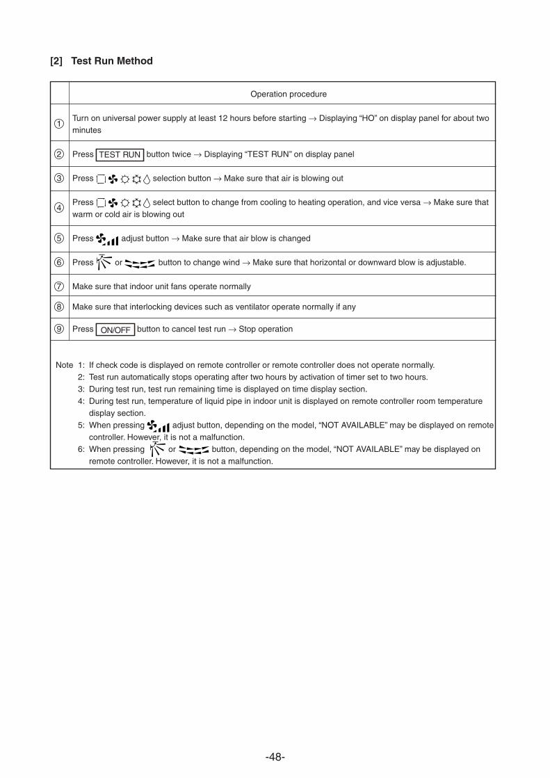
-48-
[2] Test Run Method
Operation procedure
1Turn on universal power supply at least 12 hours before starting → Displaying “HO” on display panel for about twominutes
2 Press button twice → Displaying “TEST RUN’’ on display panel
3 Press selection button → Make sure that air is blowing out
4Press select button to change from cooling to heating operation, and vice versa → Make sure that
warm or cold air is blowing out
5 Press adjust button → Make sure that air blow is changed
6 Press or button to change wind → Make sure that horizontal or downward blow is adjustable.
7 Make sure that indoor unit fans operate normally
8 Make sure that interlocking devices such as ventilator operate normally if any
9 Press button to cancel test run → Stop operation
Note 1: If check code is displayed on remote controller or remote controller does not operate normally.2: Test run automatically stops operating after two hours by activation of timer set to two hours.
3: During test run, test run remaining time is displayed on time display section.
4: During test run, temperature of liquid pipe in indoor unit is displayed on remote controller room temperaturedisplay section.
5: When pressing adjust button, depending on the model, “NOT AVAILABLE” may be displayed on remote
controller. However, it is not a malfunction.6: When pressing or button, depending on the model, “NOT AVAILABLE” may be displayed on
remote controller. However, it is not a malfunction.
TEST RUN
ON/OFF
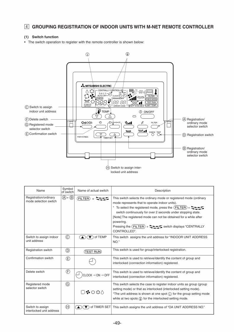
-49-
¢ GROUPING REGISTRATION OF INDOOR UNITS WITH M-NET REMOTE CONTROLLER
(1) Switch function• The switch operation to register with the remote controller is shown below:
Registration/ordinary modeselector switch
Registration/ordinarymode selection switch
Switch to assign indoorunit address
Registration switch
Confirmation switch
Delete switch
Registered modeselector switch
Switch to assigninterlocked unit address
A + B
C
D
E
F
G
H
This switch selects the ordinary mode or registered mode (ordinary
mode represents that to operate indoor units).
* To select the registered mode, press the +
switch continuously for over 2 seconds under stopping state.
[Note] The registered mode can not be obtained for a while after
powering.
Pressing the + switch displays “CENTRALLY
CONTROLLED”.
This switch assigns the unit address for “INDOOR UNIT ADDRESS
NO.”
This switch is used for group/interlocked registration.
This switch is used to retrieve/identify the content of group and
interlocked (connection information) registered.
This switch is used to retrieve/identify the content of group and
interlocked (connection information) registered.
This switch selects the case to register indoor units as group (group
setting mode) or that as interlocked (interlocked setting mode).
*The unit address is shown at one spot for the group setting mode
while at two spots for the interlocked setting mode.
This switch assigns the unit address of “OA UNIT ADDRESS NO.”
Symbolof switch
GRegistered modeselector switch
EConfirmation switch
C Switch to assignindoor unit address
Switch to assign inter-locked unit address
Registration switch
+FILTER
TEST RUN
Name Name of actual switch Description
of TEMP
of TIMER SET
CLOCK → ON → OFF
Registration/ordinary modeselector switch
STAND BY DEFROST ERROR CODE
D A I L YAUTO OFF
CENTRALLY CONTROLLED
CLOCKREMAINDER
ON OFF ˚C1Hr
NOT AVAILABLE˚C
CHECK MODE
FILTERCHECK
TEST RUN
LIMIT TEMP.
ON/OFF TEMP
FILTER
CHECK TEST
ON OFFCLOCK
PAR-F27MEA TIMER SET
FDelete switch
FILTER
FILTER
D
A
B
H
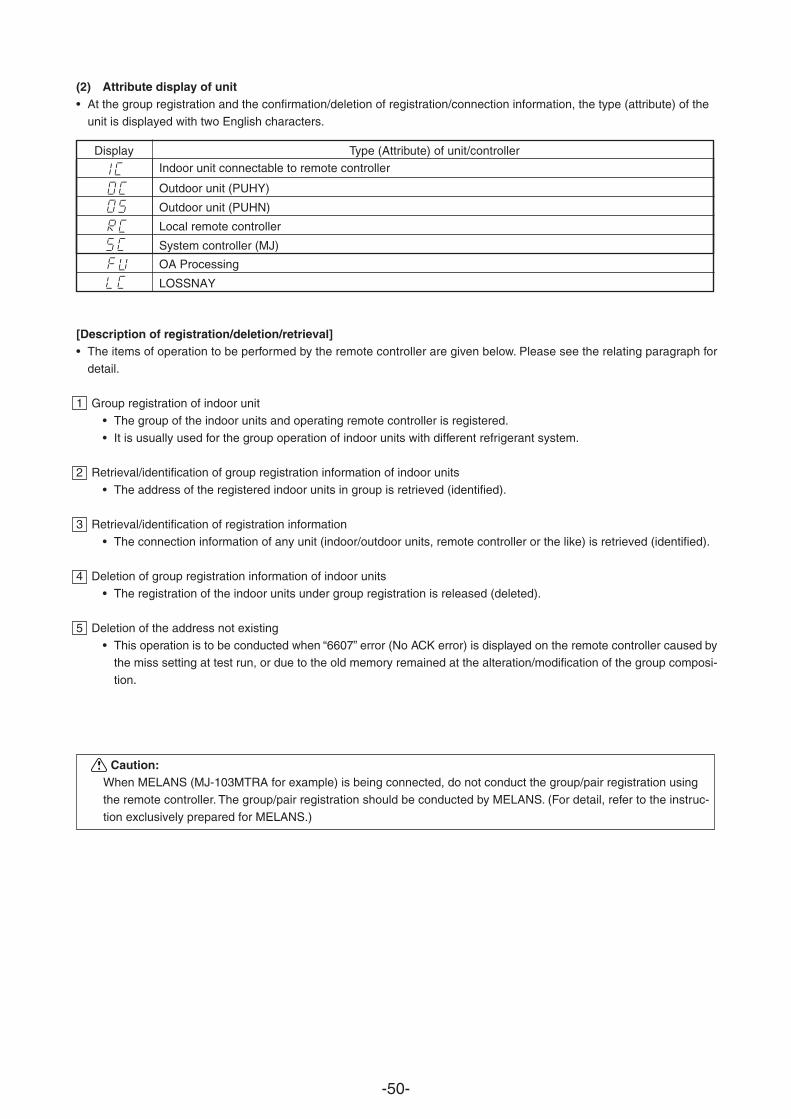
-50-
(2) Attribute display of unit• At the group registration and the confirmation/deletion of registration/connection information, the type (attribute) of the
unit is displayed with two English characters.
Display Type (Attribute) of unit/controller
Indoor unit connectable to remote controller
Outdoor unit (PUHY)
Outdoor unit (PUHN)
Local remote controller
System controller (MJ)
[Description of registration/deletion/retrieval]• The items of operation to be performed by the remote controller are given below. Please see the relating paragraph for
detail.
1 Group registration of indoor unit
• The group of the indoor units and operating remote controller is registered.
• It is usually used for the group operation of indoor units with different refrigerant system.
2 Retrieval/identification of group registration information of indoor units
• The address of the registered indoor units in group is retrieved (identified).
3 Retrieval/identification of registration information
• The connection information of any unit (indoor/outdoor units, remote controller or the like) is retrieved (identified).
4 Deletion of group registration information of indoor units
• The registration of the indoor units under group registration is released (deleted).
5 Deletion of the address not existing
• This operation is to be conducted when “6607” error (No ACK error) is displayed on the remote controller caused bythe miss setting at test run, or due to the old memory remained at the alteration/modification of the group composi-
tion.
Caution:When MELANS (MJ-103MTRA for example) is being connected, do not conduct the group/pair registration using
the remote controller. The group/pair registration should be conducted by MELANS. (For detail, refer to the instruc-
tion exclusively prepared for MELANS.)
OA Processing
LOSSNAY
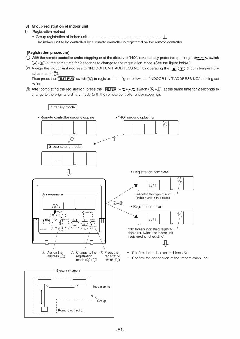
-51-
(3) Group registration of indoor unit1) Registration method
• Group registration of indoor unit ........................................................................ 1The indoor unit to be controlled by a remote controller is registered on the remote controller.
[Registration procedure]With the remote controller under stopping or at the display of “HO”, continuously press the + switch
( + ) at the same time for 2 seconds to change to the registration mode. (See the figure below.)
Assign the indoor unit address to “INDOOR UNIT ADDRESS NO.” by operating the (Room temperatureadjustment) ( ).
Then press the switch ( ) to register. In the figure below, the “INDOOR UNIT ADDRESS NO.” is being set
to 001.After completing the registration, press the + switch ( ) at the same time for 2 seconds to
change to the original ordinary mode (with the remote controller under stopping).
• Remote controller under stopping • “HO” under displaying
Ordinary mode
INDOOR UNITADDRESS NO
ERROR CODEOA UNIT ADDRESS NO
˚CINDOOR UNITADDRESS NO
ERROR CODEOA UNIT ADDRESS NO
˚C
ERROR CODEOA UNIT ADDRESS NO
˚C
Group setting mode
• Confirm the indoor unit address No.
• Confirm the connection of the transmission line.
ERROR CODEOA UNIT ADDRESS NO
˚C
ERROR CODEOA UNIT ADDRESS NO
˚C
• Registration complete
• Registration error
Indicates the type of unit(Indoor unit in this case)
“88” flickers indicating registra-tion error. (when the indoor unitregistered is not existing)
Assign theaddress ( )
Change to theregistrationmode ( )
Press theregistrationswitch ( )
Remote controller
System example
Indoor units
Group
+
ON/OFF TEMP
FILTER
CHECK TEST
ON OFFCLOCK
PAR-F27MEA TIMER SET
FILTER
FILTER
TEST RUN
+
+
1
2
3
A B
CD
BA
1 1
2 3
2 1 3
DBAC
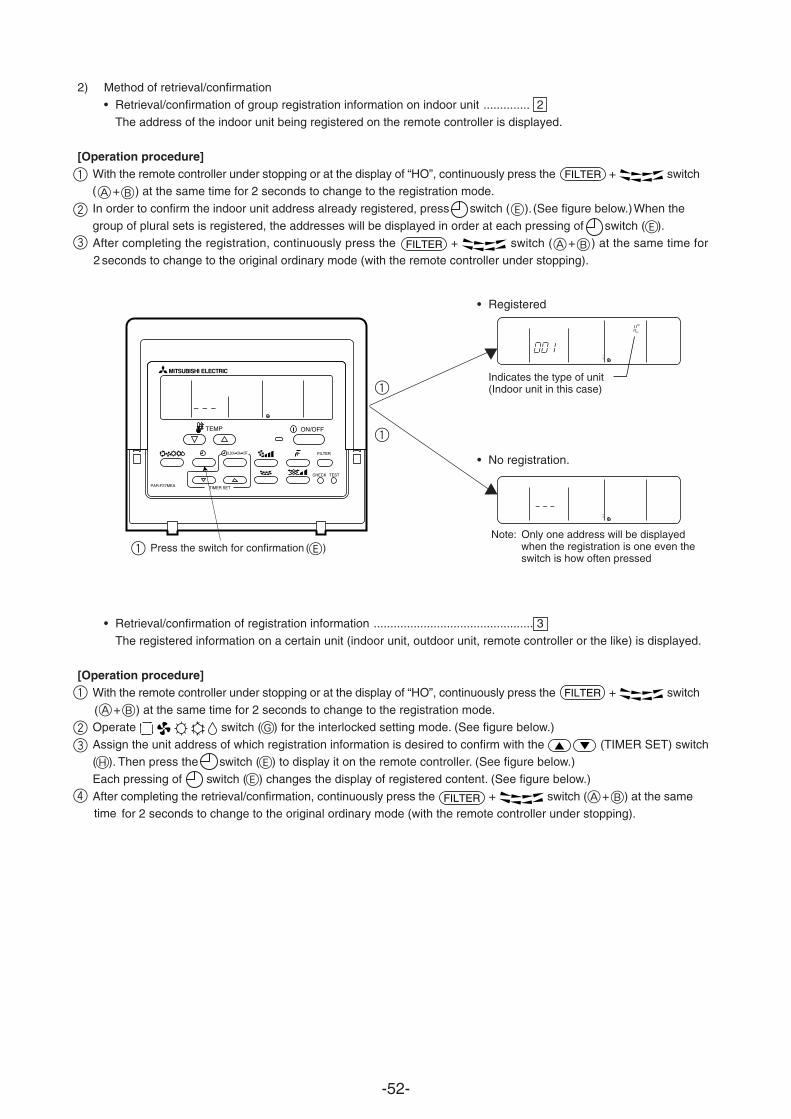
-52-
2) Method of retrieval/confirmation
• Retrieval/confirmation of group registration information on indoor unit .............. 2
The address of the indoor unit being registered on the remote controller is displayed.
[Operation procedure]
1
2
3
With the remote controller under stopping or at the display of “HO”, continuously press the + switch + B) at the same time for 2 seconds to change to the registration mode.
In order to confirm the indoor unit address already registered, press switch (E). (See figure below.) When the
of plural sets is registered, the addresses will be displayed in order at each pressing of switch ( ).After completing the registration, continuously press the + switch ( + ) at the same time for 2 seconds to change to the original ordinary mode (with the remote controller under stopping).
• Retrieval/confirmation of registration information ................................................ 3
The registered information on a certain unit (indoor unit, outdoor unit, remote controller or the like) is displayed.
[Operation procedure]With the remote controller under stopping or at the display of “HO”, continuously press the + switch
+ ) at the same time for 2 seconds to change to the registration mode.
Operate switch ( ) for the interlocked setting mode. (See figure below.)
Assign the unit address of which registration information is desired to confirm with the (TIMER SET) switch( ). Then press the switch ( ) to display it on the remote controller. (See figure below.)
Each pressing of switch ( ) changes the display of registered content. (See figure below.)
After completing the retrieval/confirmation, continuously press the + switch ( + ) at the same for 2 seconds to change to the original ordinary mode (with the remote controller under stopping).time
• Registered
• No registration.
ERROR CODEOA UNIT ADDRESS NO
˚C
ERROR CODEOA UNIT ADDRESS NO
˚C
Press the switch for confirmation ( )Note: Only one address will be displayed
when the registration is one even theswitch is how often pressed
Indicates the type of unit(Indoor unit in this case)
ON/OFF TEMP
FILTER
CHECK TEST
ON OFFCLOCK
PAR-F27MEA TIMER SET
FILTER
FILTER
FILTER
FILTER
group
(A
(
BA
E
1
1
1 E
1
23
4
BA
BA
E
E
G
H
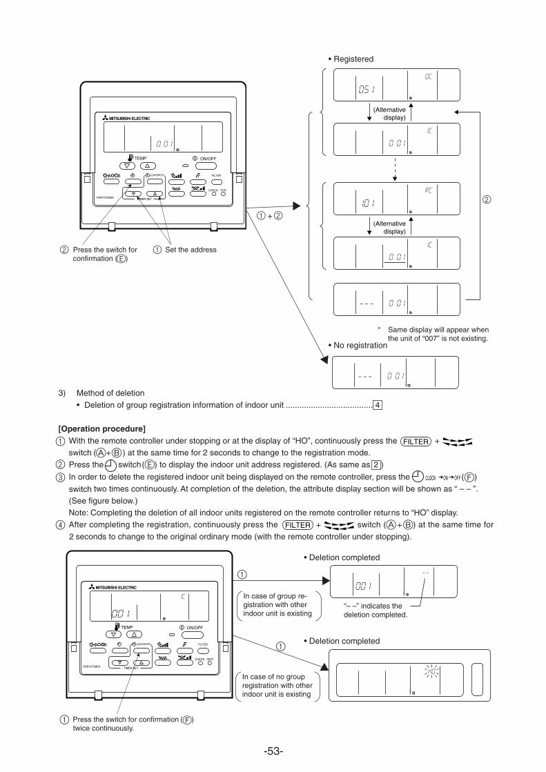
-53-
3) Method of deletion
• Deletion of group registration information of indoor unit ...................................... 4
[Operation procedure]With the remote controller under stopping or at the display of “HO”, continuously press the + switch ( + ) at the same time for 2 seconds to change to the registration mode.
Press the switch ( ) to display the indoor unit address registered. (As same as 2 )
In order to delete the registered indoor unit being displayed on the remote controller, press the ( )
two times continuously. At completion of the deletion, the attribute display section will be shown as “ – – ”.switch(See figure below.)Note: Completing the deletion of all indoor units registered on the remote controller returns to “HO” display.
After completing the registration, continuously press the + switch ( + ) at the same time for
seconds to change to the original ordinary mode (with the remote controller under stopping).
ERROR CODEOA UNIT ADDRESS NO
˚C
INDOOR UNITADDRESS NO
ERROR CODEOA UNIT ADDRESS NO
˚C
INDOOR UNITADDRESS NO
ERROR CODEOA UNIT ADDRESS NO
˚C
Set the address2 Press the switch forconfirmation ( )
• Registered
• No registration
* Same display will appear whenthe unit of “007” is not existing.
Press the switch for confirmation ( )twice continuously.
• Deletion completed
• Deletion completed
In case of group re-gistration with otherindoor unit is existing
In case of no groupregistration with otherindoor unit is existing
+
“– –” indicates thedeletion completed.
(Alternativedisplay)
(Alternativedisplay)
ON/OFF TEMP
FILTER
CHECK TEST
ON OFFCLOCK
PAR-F27MEA TIMER SET
ON/OFF TEMP
FILTER
CHECK TEST
ON OFFCLOCK
PAR-F27MEA TIMER SET
ON OFFCLOCK
FILTER
FILTER
2
E
F
1
1 2
2
2
1
3
A BE
F
A B4
1
1
1
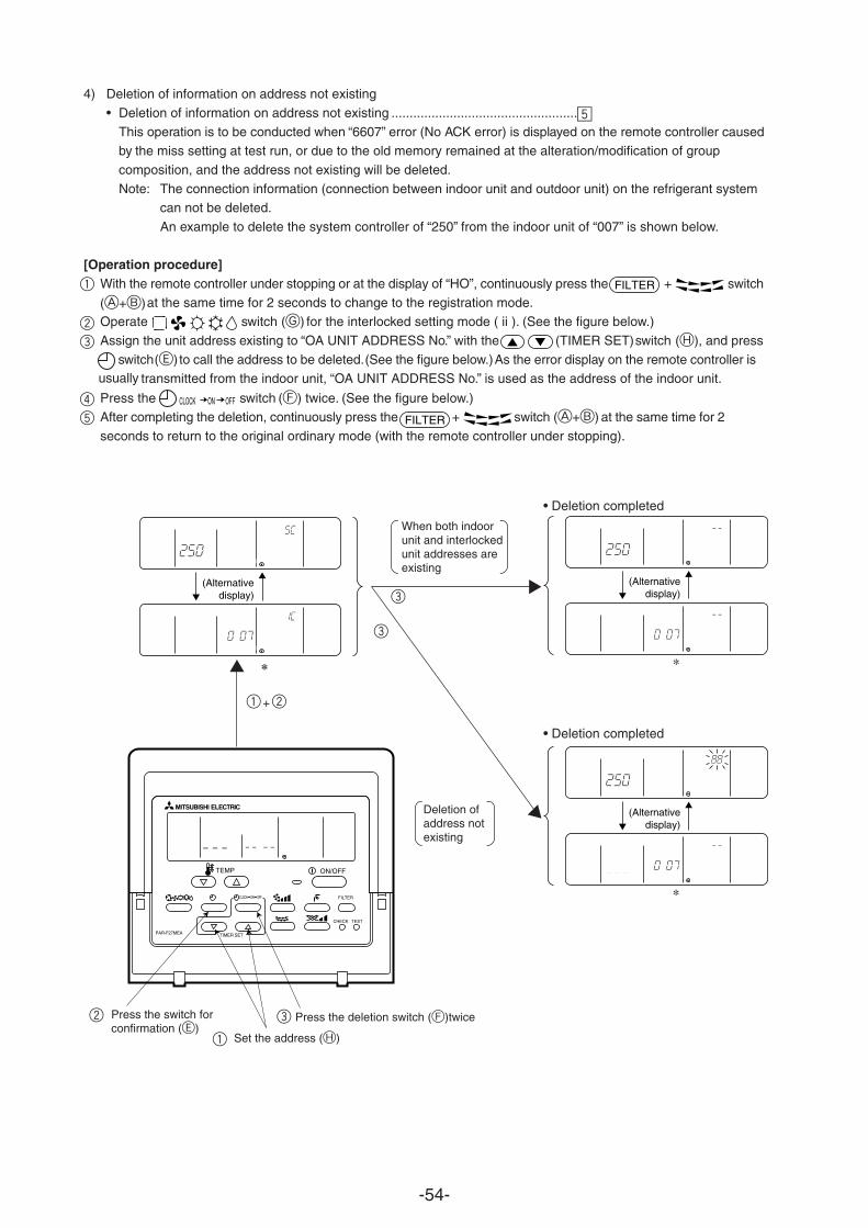
-54-
4) Deletion of information on address not existing
• Deletion of information on address not existing ...................................................
This operation is to be conducted when “6607” error (No ACK error) is displayed on the remote controller caused by the miss setting at test run, or due to the old memory remained at the alteration/modification of group
composition, and the address not existing will be deleted.
Note: The connection information (connection between indoor unit and outdoor unit) on the refrigerant system can not be deleted.
An example to delete the system controller of “250” from the indoor unit of “007” is shown below.
[Operation procedure]With the remote controller under stopping or at the display of “HO”, continuously press the + switch
at the same time for 2 seconds to change to the registration mode.Operate switch (G) for the interlocked setting mode ( ii ). (See the figure below.)
Assign the unit address existing to “OA UNIT ADDRESS No.” with the (TIMER SET) switch (H), and press
switch to call the address to be deleted. (See the figure below.) As the error display on the remote controller is transmitted from the indoor unit, “OA UNIT ADDRESS No.” is used as the address of the indoor unit.usually
Press the switch (F) twice. (See the figure below.)After completing the deletion, continuously press the + switch at the same time for 2
seconds to return to the original ordinary mode (with the remote controller under stopping).
INDOOR UNITADDRESS NO
ERROR CODEOA UNIT ADDRESS NO
˚C
INDOOR UNITADDRESS NO
ERROR CODEOA UNIT ADDRESS NO
˚C
(Alternativedisplay)
INDOOR UNITADDRESS NO
ERROR CODEOA UNIT ADDRESS NO
˚C
INDOOR UNITADDRESS NO
ERROR CODEOA UNIT ADDRESS NO
˚C
(Alternativedisplay)
*
INDOOR UNITADDRESS NO
ERROR CODEOA UNIT ADDRESS NO
˚C
INDOOR UNITADDRESS NO
ERROR CODEOA UNIT ADDRESS NO
˚C
(Alternativedisplay)
*
When both indoorunit and interlockedunit addresses areexisting
Deletion ofaddress notexisting
Set the address (H)
Press the deletion switch
• Deletion completed
• Deletion completed
1 2+
Press the switch forconfirmation (E)
ON/OFF TEMP
FILTER
CHECK TEST
ON OFFCLOCK
PAR-F27MEA TIMER SET
FILTER
FILTER
ON OFFCLOCK
∞
1
5
4
3
2
3
3
3
1
2 (F)twice
(A+B)
(E)
(A+B)
-55-
∞ CONTROL
[1] Control of Outdoor Unit
[1]- 1 PUHY-P400·500 YMF-C
(1) Initial processing• When turning on power source, initial processing of microcomputer is given top priority.• During initial processing, control processing corresponding to operation signal is suspended. The control processing
is resumed after initial processing is completed. (Initial processing: Data processing in microcomputer and initial
setting of each LEV opening, requiring approx. 2 minutes at the maximum.)
(2) Control at staring• For 3 minutes after starting, 60 Hz is the upper frequency limit. (When only No. 1 compressor is operating.)• 75 Hz is the upper limit within 2 hours after the power supply has been turned ON and for the 30 minutes after the
compressor has started operation.
• Normal control is performed after the initial start mode (described later) has been completed.
(3) Compressor capacity control• Variable capacitor compressor is performed by the variable capacity compressor (No. 1: inverter motor) and
constant capacity compressor (No. 2: It has capacity control switching).• In response to the required performance, the number of compressors operating, the switching of capacity control
and the frequency of the variable capacity compressor is controlled so that the evaporation temperature isbetween – 2 and – 6˚C in cooling mode and that the condensation temperature is 49˚C in heating mode.
• The fluctuation of the frequency of the variable capacity compressor is as follows. It is performed at 2 Hz per
second.20 to 100 Hz (TH6 > 20˚C and in cooling mode, or in heating mode)30 to 100 Hz (TH6 < 20˚C and in cooling mode)
1) No. 2 compressor operation, stopping and full-load/un-load switching
1 Switching from stopping to operation of No. 2 compressor.
When the required performance cannot be obtained by only No. 1 compressor, the No. 2 compressor will bestarted. (The No. 2 compressor will be started in un-load operation.)• After the No. 1 compressor has reached 100 Hz, the No. 2 compressor stops un-load or un-load full-load.
2 Switching from operation to stopping of No. 2 compressor.When the required performance is exceeded when the two compressors, No. 1 and No. 2, are operating, the No.
2 compressor is stopped or performed in un-load operation.
3 Switching from un-load to full-load of No. 2 compressor
When the required performance cannot be obtained by the No. 1 compressor and the No. 2 compressor operat-ing in un-load, the No. 2 compressor will be switched to full-load operation.
4 Switching from full-load to un-load of No. 2 compressorWhen the required performance is exceeded when the two compressors, No.1 and No. 2 operating in full-load,the No 2 compressor will be switched to un-load operation.
2) Pressure control
The upper limit value for the high pressure (Pd) has been set for each frequency. When this value is exceeded, the
xceeded, the
frequency is reduced every 30 seconds.3) Discharge temperature control
The discharge temperature of the compressor (Td) is monitored during the operation. If the upper limit is efrequency is reduced by 5 Hz.• Control is performed every 30 seconds after 30 seconds at the compressor starting.
-56-
• The operating temperature is 124˚C (No. 1 compressor) or 115˚C (No. 2 compressor).
4) Compressor frequency control1 Ordinary control
The ordinary control is performed after the following times have passed.• 30 seconds after the start of the compressor or 30 seconds after the completion of defrosting.• 30 seconds after frequency control operation by the discharge temperature or the high pressure.
2 Amount of frequency fluctuationThe amount of frequency fluctuation is controlled in response to the evaporation temperature (Te) and thecondensation temperature (Tc) so that it will approached the target values.
3 Frequency control back-up by the bypass valveFrequency control is backis operated at its lowest frequency.• Cooling
After the compressor has been operated for 15 minutes and only the No. 1 compressor is operated in un-load(its lowest frequency), the bypass vturned OFF when it is 0.196 MPa or more.
• HeatingAfter the compressor has been operated for 3 minutes and only the No. 1 compressor is operated in un-load(its lowest frequency), the bypass valve is turned ON when the high pressure (Pd) exceeds 27 kg/cm2 (2.65MPa) and turned OFF when it is 24 kg/cm2 (2.35 MPa) or less.
(4) Bypass - capacity controlThe solenoid valves have bypass valves (SV1, SV4 and SV6) that allow bypassing of the high pressure and lowpressure sides and solenoid valves (SV22 and SV32) that control the capacity control valve inside the compressor.
They operate as follows.1) Bypass valve (SV6) [SV6 is on (open)]
• As shown in the table below, control is performed by the operation and stopping of the No. 1 compressor and No.2
compressor.
No. 1 compressor No. 2 compressor SV6Stop Stop OFF
Operate Stop ON
Operate Operate OFF
ON
OFF
ON
OFF
alve is turned ON when the low pressure (63 LS) is 0.098 MPa or less and
0.098 MPa 0.196 MPa
2.35 MPa 2.65 MPa
ed-up by turning on (opening) the bypass valve (SV4) when only the No.1 compressor
-57-
Item
At compressor is started
Compressor stopped during cool-ing or heating mode
After operation has been stopped
During defrosting ((*1) in Fig below)
During oil recovery operation
When low pressure (Ps) hasdropped during lower limit fre-quency operation(15 minutes af-ter start)
When the high pressure (Pd) isrisen up during lower limit fre-quency operation (3 minutes afterstarting)
When the discharge temperature(Td) is risen up
Ps
Pd after 30 seconds
Pd
* Example of operation of SV1
Compressor
Bypasssolenoidvalve (SV1)
(4-minute) (2-minute) (4-minute) (3-minute)
Start Thermo.OFF
Thermo.ON
Defrost Stop
2) Bypass solenoid valves (SV1, SV4) [Both SV1 and SV4 are on (open)]
ON OFF
SV1
ON for 4 minutes
ON
ON for 3 minutes
ON
ON during oil recovery operation af-ter continuous low-frequency com-pressor operation.
—
—
—
ON
Ps <
Pd
ON when the high pres-sure (Pd) exceeds thecontrol pressure limit.
OFF
SV4
—
—
—
Normally ON
—
3) Capacity control solenoid valve (SV22, SV32). (Model 500 only)
• Operation of solenoid valve
• SV22 and SV32 stand for SV2 and SV3 of the No. 2compressor.
Solenoid valve
SV22
SV32
COMP
SV22 SV32
Coil Valve Coil Valve
OFF Open OFF Closed
ON Closed ON Open
StatusFull-load(Operating at 100 %capacity)
Un-load(Capacity controloperation)
Pd Pd
130˚C(No. 1 compressor)115˚C(No. 2 compressor) 2 compressor)
• Td >
and• Pd >
orPs <
115˚C(No. 1 compressor)100˚C(No.
Td
0.196 MPa0.098 MPa
2.65 MPa 2.35 MPa and 2.70 MPa 2.35 MPa
and after 30 seconds.
1.96 MPa
1.96 MPa
0.34 MPa
-58-
(5) Oil return control (Electronic expansion valve (SLEV))• The amount of opening of the oil-return LEV (SLEV) is determined as follows: in cooling, by the operating capacity
of the No. 1 compressor and the ambient temperature; in heating, by the operating capacity of the No. 1 compressor.
• It is opened (64pulses) when both compressors are stopped and started for 10 minutes. (Upper limit of LEV openingis So = 388 pulse.)
• SLEV = 0 when the No. 1 compressor is stopped.
(7) Defrosting control1) Start of defrosting
• After there has been heating operation for 50 minutes or after 90 minutes has passed and a piping temperature(TH5) of – 8 C or less is detected for a preset time, defrosting begins.
• When 10 minutes has passed since the compressor began operation or for forced defrosting (Setting of Dip SW2-7 on) when 10 minutes has passed since recovery from defrosting forced defrost mode recomes active.
2) End of defrosting
• Defrosting ends when 12 minutes have passed since the start of defrosting, or when a piping temperature (TH5 andTH7) of 7 C or more is detected for 4 minutes or longer. (Note that if the defrost-prohibited time is set on 90 minutes,the defrost-prohibit time will be 50 minutes following a 12-minute timed recovery.
• Ending the defrosting is prohibited for 4 minutes after the start of defrosting.3) Defrost-prohibit
• Defrosting is not performed for 10 minutes after the start of compressor operation and during oil recovery mode.
4) Abnormalities during defrosting• If an error is detected during defrosting, the defrosting is stopped and the defrost-prohibit time is set to 20 minutes
by the compressor cumulative operating time
(6) Sub-cool coil control (Electronic expansion valve (LEV1))• The sub-cool coil control provides control every 30 seconds to keep the super heat volume from the temperature of
the inlet/outlet of the sub-cool coil (TH8, TH9) within a stable range (2 to 4 degrees).• It controls by correcting the amount of opening according to the temperature of the inlet/outlet of the sub-cool coil
(TH5, TH7), the high pressure (Pd) and discharge temperature.• It is closed (0) in heating or when the compressor is stopped.• It has a fixed opening (480) in defrosting.
• During normal control, the operating range is 46 to 480.
5) Change in number of operating indoor units while defrosting• If the number of indoor units changes while the outdoor unit is defrosting, the defrosting operation continues. Once
defrosting has ended, control for changing the number of units is performed.• If the indoor unit is stopped while the outdoor unit is defrosting or if the thermostat is set to off, the defrosting
operation continues. Once defrosting has ended, the unit is stopped.6) Number of compressors operating during defrosting
• The number of compressors operating during defrosting is always two.
(8) Control of liquid level detecting heaterDetect refrigerant liquid level in accumulator, and heat refrigerant with liquid level heater for judging refrigerant amount.7 steps of duty control is applied to liquid level heater depending on frequency and outdoor air temperature, 1 minuteafter starting compressor.
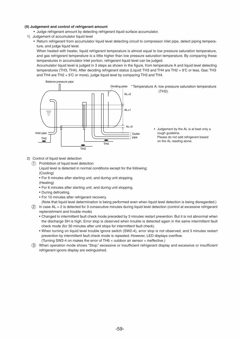
-59-
(9) Judgement and control of refrigerant amount• Judge refrigerant amount by detecting refrigerant liquid surface accumulator.
1) Judgement of accumulator liquid level• Return refrigerant from accumulator liquid level detecting circuit to compressor inlet pipe, detect piping tempera-
ture, and judge liquid level.When heated with heater, liquid refrigerant temperature is almost equal to low pressure saturation temperature,and gas refrigerant temperature is a little higher than low pressure saturation temperature. By comparing these
Accumulator liquid level is judged in 3 steps as shown in the figure, from temperature A and liquid level detectingtemperatures (TH3, TH4). After deciding refrigerant status (Liquid: TH3 and TH4 are TH2 + 9˚C or less, Gas: TH3and TH4 are TH2 + 9˚C or more), judge liquid level by comparing TH3 and TH4.
2) Control of liquid level detection1 Prohibition of liquid level detection
Liquid level is detected in normal conditions except for the following;(Cooling)• For 6 minutes after starting unit, and during unit stopping.(Heating)• For 6 minutes after starting unit, and during unit stopping.• During defrosting.• For 10 minutes after refrigerant recovery.
(Note that liquid level determination is being performed even when liquid level detection is being disregarded.)2 In case AL = 2 is detected for 3 consecutive minutes during liquid level detection (control at excessive refrigerant
replenishment and trouble mode)• Changed to intermittent fault check mode preceded by 3 minutes restart prevention. But it is not abnormal when
the discharge SH is high. Error stop is observed when trouble is detected again in the same intermittent faultcheck mode (for 30 minutes after unit stops for intermittent fault check).
• When turning on liquid level trouble ignore switch (SW2-4), error stop is not observed, and 3 minutes restartprevention by intermittent fault check mode is repeated. However, LED displays overflow.(Turning SW2-4 on makes the error of TH6 < outdoor air sensor > ineffective.)
3 When operation mode shows “Stop,” excessive or insufficient refrigerant display and excessive or insufficientrefrigerant ignore display are extinguished.
TH3
TH4
Balance pressure pipe
TH2
AL=0
AL=1
AL=2
Dividing plate
Outletpipe
Inlet pipe• Judgement by the AL is at best only a
rough guideline.Please do not add refrigerant basedon the AL reading alone.
*Temperature A: low pressure saturation temperature(TH2).
temperatures in accumulator inlet portion, refrigerant liquid level can be judged.
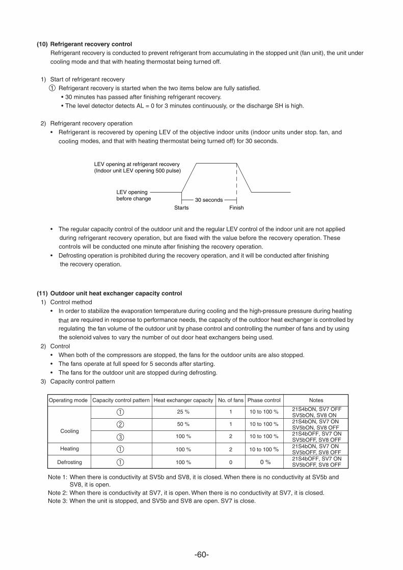
-60-
(11) Outdoor unit heat exchanger capacity control1) Control method
• In order to stabilize the evaporation temperature during cooling and the high-pressure pressure during heating
are required in response to performance needs, the capacity of the outdoor heat exchanger is controlled by the fan volume of the outdoor unit by phase control and controlling the number of fans and by using
valves to vary the number of out door heat exchangers being used.the solenoid
2) Control• When both of the compressors are stopped, the fans for the outdoor units are also
regulating
stopped.• The fans operate at full speed for 5 seconds after starting.
• The fans for the outdoor unit are stopped during defrosting.3) Capacity control pattern
(10) Refrigerant recovery controlRefrigerant recovery is conducted to prevent refrigerant from accumulating in the stopped unit (fan unit), the unit undercooling mode and that with heating thermostat being turned off.
1) Start of refrigerant recovery1 Refrigerant recovery is started when the two items below are fully satisfied.
• 30 minutes has passed after finishing refrigerant recovery.• The level detector detects AL = 0 for 3 minutes continuously, or the discharge SH is high.
2) Refrigerant recovery operation• Refrigerant is recovered by opening LEV of the objective indoor units (indoor units under stop. fan, and
modes, and that with heating thermostat being turned off) for 30 seconds.cooling
• The regular capacity control of the outdoor unit and the regular LEV control of the indoor unit are not applied refrigerant recovery operation, but are fixed with the value before the recovery operation. These
conducted one minute after finishing the recovery operation.
• Defrosting operation is prohibited during the recovery operation, and it will be conducted after finishing operation.the recovery
Starts
LEV openingbefore change
LEV opening at refrigerant recovery(Indoor unit LEV opening 500 pulse)
Finish30 seconds
Note 1:
Note 2: When there is conductivity at SV7, it is open. When there is no conductivity at SV7, it is closed.Note 3: When the unit is stopped, and SV5b and SV8 are open. SV7 is close.
Operating mode Capacity control pattern Heat exchanger capacity No. of fans Phase control Notes
2
3
1
1
50 % 1 10 to 100 %
100 % 2 10 to 100 %
100 % 2 10 to 100 %
100 % 0 0 %
Cooling
Heating
Defrosting
21S4bON, SV7 ONSV5bON, SV8 OFF
1 25 % 1 10 to 100 % 21S4bON, SV7 OFFSV5bON, SV8 ON
21S4bOFF, SV7 ONSV5bOFF, SV8 OFF21S4bON, SV7 ONSV5bOFF, SV8 OFF21S4bOFF, SV7 ONSV5bOFF, SV8 OFF
duringcontrols will be
that
When there is conductivity at SV5b and SV8, it is closed. When there is no conductivity at SV5b and SV8, it is open.
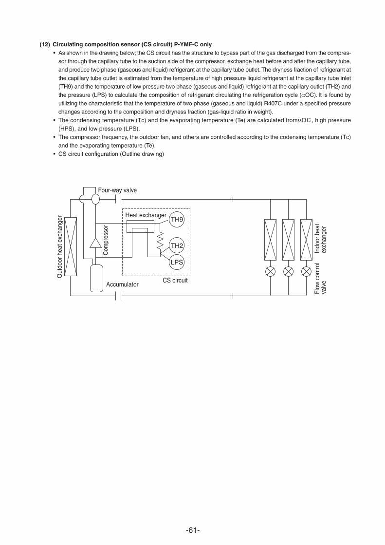
-61-
TH9
Four-way valve
Com
pres
sor
AccumulatorCS circuit
TH2
LPS
Heat exchanger
Out
door
hea
t exc
hang
er
Indo
or h
eat
exch
ange
rFl
ow c
ontro
l va
lve
(12) Circulating composition sensor (CS circuit) P-YMF-C only• As shown in the drawing below; the CS circuit has the structure to bypass part of the gas discharged from the compres-
sor through the capillary tube to the suction side of the compressor, exchange heat before and after the capillary tube,and produce two phase (gaseous and liquid) refrigerant at the capillary tube outlet. The dryness fraction of refrigerant at
the capillary tube outlet is estimated from the temperature of high pressure liquid refrigerant at the capillary tube inlet(TH9) and the temperature of low pressure two phase (gaseous and liquid) refrigerant at the capillary outlet (TH2) andthe pressure (LPS) to calculate the composition of refrigerant circulating the refrigeration cycle C). It is found by
utilizing the characteristic that the temperature of two phase (gaseous and liquid) R407C under a specified pressurechanges according to the composition and dryness fraction (gas-liquid ratio in weight).
• The condensing temperature (Tc) and the evaporating temperature (Te) are calculated from C , high pressure
(HPS), and low pressure (LPS).• The compressor frequency, the outdoor fan, and others are controlled according to the codensing temperature (Tc)
and the evaporating temperature (Te).
• CS circuit configuration (Outline drawing)
(

-62-
(13) Control at initial starting• When the ambient temperature is low (5 C or less in cooling and – 5 C or less in heating), initial starting will be
performed if the unit is started within 4 hours of the power being turned on.
• The following initial start mode will be performed when the unit is started for the first time after the power hasbeen turned on.
<Flow chart of initial start mode>
Start of initial operation mode
Initial operation mode is finished.
Step 1
•••
Only the No.1 compressor is operated (f 75 Hz)Operation of the No.2 compressor is prohibited.Finished when cumulative operating time reaches 30 minutes.
Pause Step
• Both compressors are stopped, regardless of thedemand from the indoor units. (3 minutes)
Step 2
•••
Only the No.1 compressor is operated. Operation of the No.2 compressor is prohibited.Operates continuously for 10 minutes and finishes.
Step 3
•
•
Both compressors, No.1 and No.2, are operated (Forced)Finished when cumulative operating time reaches 30 minutes.
At the completion of Step 2, if the frequency of No.1 compressor is below the specified value and if Step 2 has been completed less than 3 times, the process does not proceed to Step 3 but rather enters the Pause Step and then repeats Step 2.
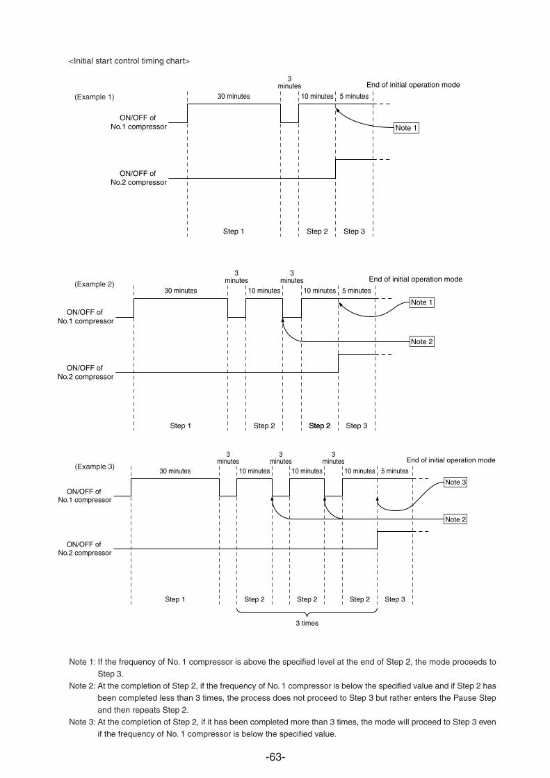
-63-
<Initial start control timing chart>
Note 1: If the frequency of No. 1 compressor is above the specified level at the end of Step 2, the mode proceeds to
Step 3.Note 2: At the completion of Step 2, if the frequency of No. 1 compressor is below the specified value and if Step 2 has
been completed less than 3 times, the process does not proceed to Step 3 but rather enters the Pause Step
and then repeats Step 2.Note 3: At the completion of Step 2, if it has been completed more than 3 times, the mode will proceed to Step 3 even
if the frequency of No. 1 compressor is below the specified value.
30 minutes
Step 1
3minutes
10 minutes
Step 2
5 minutes
Step 3
ON/OFF of No.1 compressor
ON/OFF of No.2 compressor
End of initial operation mode
Note 1
30 minutes
Step 1
3minutes
10 minutes
Step 2
3minutes
10 minutes
Step 2Step 2
5 minutes
Step 3
Note 1ON/OFF of
No.1 compressor
ON/OFF of No.2 compressor
Note 2
End of initial operation mode
30 minutes
Step 1
3minutes
10 minutes
Step 2
3minutes
10 minutes
Step 2
3 times
3minutes
10 minutes
Step 2
5 minutes
Step 3
Note 3ON/OFF of
No.1 compressor
ON/OFF of No.2 compressor
Note 2
End of initial operation mode
(Example 1)
(Example 2)
(Example 3)
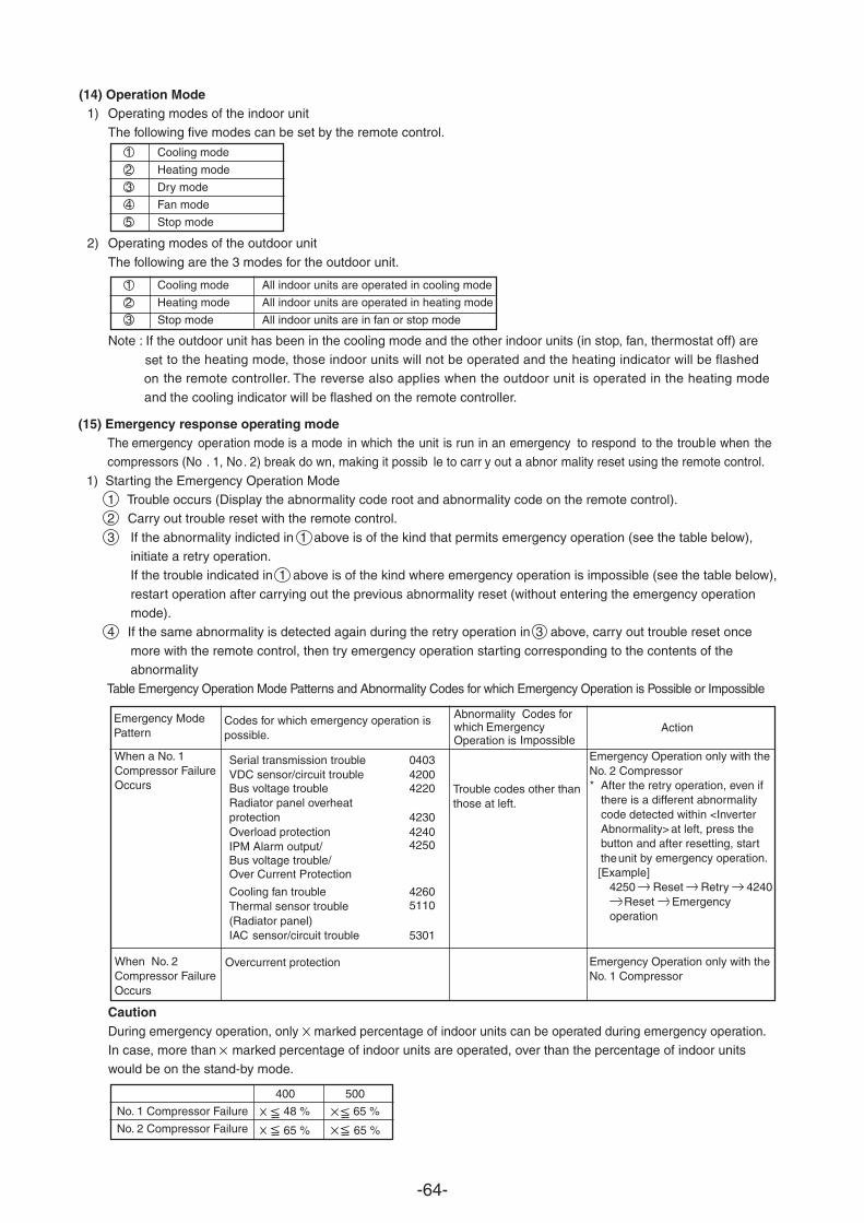
-64-
(14) Operation Mode1) Operating modes of the indoor unit
The following five modes can be set by the remote control.
1 Cooling mode
2 Heating mode
3 Dry mode
4 Fan mode
5 Stop mode
2) Operating modes of the outdoor unit
The following are the 3 modes for the outdoor unit.
1 Cooling mode All indoor units are operated in cooling mode
2 Heating mode All indoor units are operated in heating mode
3 Stop mode All indoor units are in fan or stop mode
Note : If the outdoor unit has been in the cooling mode and the other indoor units (in stop, fan, thermostat off) are to the heating mode, those indoor units will not be operated and the heating indicator will be flashed
remote controller. The reverse also applies when the outdoor unit is operated in the heating mode the
the cooling indicator will be flashed on the remote controller.and
CautionDuring emergency operation, only marked percentage of indoor units can be operated during emergency operation.In case, more than marked percentage of indoor units are operated, over than the percentage of indoor unitswould be on the stand-by mode.
Codes for which emergency operation ispossible.
Emergency ModePattern
Codes for AbnormalityEmergency which
ImpossibleOperation isAction
When a No. 1Compressor FailureOccurs
When No. 2Compressor FailureOccurs
Trouble codes other thanthose at left.
Emergency Operation only with theNo. 2 Compressor * After the retry operation, even if
there is a diffdetected
erent abnormalitywithin <Invertercode
at left, press the Abnormality>and after resetting, start buttonby emergency operation.the unit
[Example]4250 Reset Retry 4240
Reset Emergencyoperation
Emergency Operation only with theNo. 1 Compressor
Overcurrent protection
400 500
No. 1 Compressor Failure 48 % 65 %
No. 2 Compressor Failure 65 % 65 %
(15) Emergency response operating modeThe emergency operation mode is a mode in which the unit is run in an emergency to respond to the trouble when thecompressors (No . 1, No. 2) break do wn, making it possib le to carr y out a abnor mality reset using the remote control.
1) Starting the Emergency Operation Mode1 Trouble occurs (Display the abnormality code root and abnormality code on the remote control).2 Carry out trouble reset with the remote control.
3 If the abnormality indicted in 1 above is of the kind that permits emergency operation (see the table below),initiate a retry operation.If the trouble indicated in 1 above is of the kind where emergency operation is impossible (see the table below),
restart operation after carrying out the previous abnormality reset (without entering the emergency operationmode).
4 If the same abnormality is detected again during the retry operation in 3 above, carry out trouble reset once
more with the remote control, then try emergency operation starting corresponding to the contents of theabnormality
Table Emergency Operation Mode Patterns and Abnormality Codes for which Emergency Operation is Possible or Impossible
seton
Serial transmission trouble 0403VDC sensor/circuit trouble 4200Bus voltage trouble 4220Radiator panel overheatprotection 4230Overload protection 4240
4250IPM Alarm output/Bus voltage trouble/Over Current Protection
Cooling fan trouble 4260Thermal sensor trouble(Radiator panel)
5110
IAC sensor/circuit trouble 5301
-65-
[1]-2 PUHY-400·500 YMF-C
(1) Initial processing• When turning on power source, initial processing of microcomputer is given top priority.• During initial processing, control processing corresponding to operation signal is suspended. The control
is resumed after initial processing is completed. (Initial processing: Data processing in processingsetting of each LEV opening, requiring approx. 2 minutes at the maximum.)
(2) Control at staring• For 3 minutes after starting, 60 Hz is the upper frequency limit. (When only No. 1 compressor is operating.)• 75 Hz is the upper limit within 2 hours after the power supply has been turned ON and for the 30 minutes after the
compressor has started operation.
• Normal control is performed after the initial start mode (described later) has been completed.
(3) Compressor capacity control• Variable capacitor compressor is performed by the variable capacity compressor (No. 1: inverter motor) and
constant capacity compressor (No. 2: Model 500 has capacity control switching, Model 400 does not).• In response to the required performance, the number of compressors operating, the switching of capacity control
and the frequency of the variable capacity compressor is controlled so that the evaporation temperature isbetween 0 and 5 C in cooling mode and that the high pressure is between 1.76 and 1.96 MPa in heating mode.
• The fluctuation of the frequency of the variable capacity compressor is as follows. It is performed at 2 Hz persecond.20 to 100 Hz (TH6 > 20 C and in cooling mode, or in heating mode)
30 to 100 Hz (TH6 < 20˚C and in cooling mode)
1) No. 2 compressor operation, stopping and full-load/un-load switching
Switching from stopping to operation of No. 2 compressor.When the required performance cannot be obtained by only No. 1 compressor, the No. 2 compressor will bestarted. (On Model 500, the No. 2 compressor will be started in un-load operation.)
• Model 400: After the No. 1 compressor has reached 98 Hz, the No. 2 compressor stops starts.• Model 500: After the No. 1 compressor has reached 100 Hz, the No. 2 compressor stops un-load or un-load
full-load.
Switching from operation to stopping of No. 2 compressor.When the required performance is exceeded when the two compressors, No. 1 and No. 2, are operating, the No.
2 compressor is stopped. (On Model 500, the No. 2 compressor will be performed in un-load operation.)
Switching from un-load to full-load of No. 2 compressor (Model 500 only)
When the required performance cannot be obtained by the No. 1 compressor and the No. 2 compressor operat-ing in un-load, the No. 2 compressor will be switched to full-load operation.
Switching from full-load to un-load of No. 2 compressor (Model 500 only)When the required performance is exceeded when the two compressors, No.1 and No. 2 operating in full-load,the No 2 compressor will be switched to un-load operation.
2) Pressure control
The upper limit value for the high pressure (Pd) has been set for each frequency. When this value is exceeded, frequency is reduced every 30 seconds.the
3) Discharge temperature control
The discharge temperature of the compressor (Td) is monitored during the operation. If the upper limit is exceeded, frequency is reduced by 5 Hz.the
• Control is performed every 30 seconds after 30 seconds at the compressor starting.
microcomputer and initial
1
2
3
4
-66-
• The operating temperature is 124˚C.
4) Compressor frequency controlOrdinary controlThe ordinary control is performed after the following times have passed.• 30 seconds after the start of the compressor or 30 seconds after the completion of defrosting.• 30 seconds after frequency control operation by the discharge temperature or the high pressure.Amount of frequency fluctuationThe amount of frequency fluctuation is controlled in response to the evaporation temperature (TH2) and the highpressure (Pd) so that it will approached the target values.Frequency control back-up by the bypass valveFrequency control is backed-up by turning on (opening) the bypass valve (SV4) when only the No.1 compressor .
• CoolingAfter the compressor has been operated for 15 minutes and only the No. 1 compressor is operated in un-load(its lowest frequency), the bypass valve is turned ON when the evaporation temperature (TH2) is – 30˚C orless and turned OFF when it is – 15˚C or more.
• HeatingAfter the compressor has been operated for 3 minutes and only the No. 1 compressor is operated in un-load(its lowest frequency), the bypass valve is turned ON when the high pressure (Pd) exceeds 2.45 MPa andturned OFF when it is 1.96 MPa) or less.
(4) Bypass - capacity controlThe solenoid valves have bypass valves (SV1, SV4 and SV6) that allow bypassing of the high pressure and lowpressure sides and solenoid valves (SV22 and SV32) that control the capacity control valve inside the compressor.
They operate as follows.1) Bypass valve (SV6) [SV6 is on (open)]
• As shown in the table below, control is performed by the operation and stopping of the No. 1 compressor and
compressor.No. 2
No. 1 compressor No. 2 compressor SV6Stop Stop OFF
Operate Stop ON
Operate Operate OFF
ON
OFF1.96 MPa 2.45 MPa
– 30 ˚C
ON
OFF– 15˚C
1
2
3
is operated at its lowest frequency.
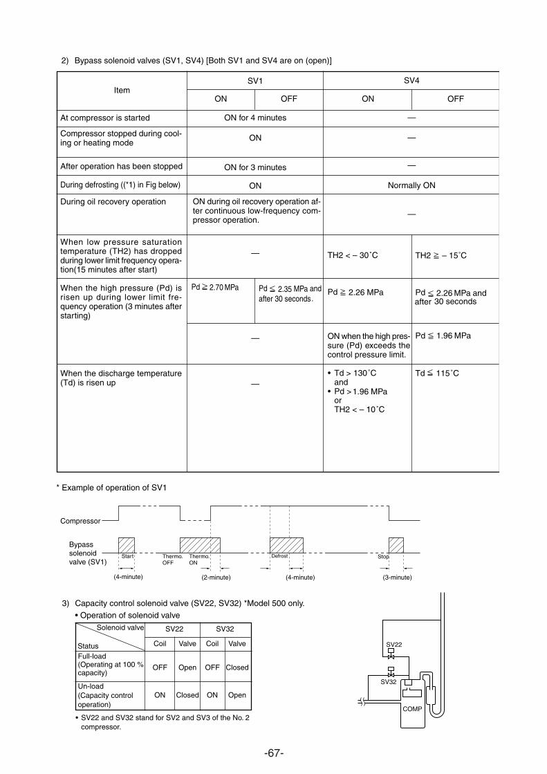
-67-
Item
At compressor is started
Compressor stopped during cool-ing or heating mode
After operation has been stopped
During defrosting ((*1) in Fig below)
During oil recovery operation
When low pressure saturationtemperature (TH2) has droppedduring lower limit frequency opera-tion(15 minutes after start)
When the high pressure (Pd) isrisen up during lower limit fre-quency operation (3 minutes afterstarting)
When the discharge temperature(Td) is risen up
TH2 – 15˚C
Pd 2.26 MPa and after 30 seconds
Pd 1.96 MPa
Td 115˚C
* Example of operation of SV1
Compressor
Bypasssolenoidvalve (SV1)
(4-minute) (2-minute) (4-minute) (3-minute)
Start Thermo.OFF
Thermo.ON
Defrost Stop
2) Bypass solenoid valves (SV1, SV4) [Both SV1 and SV4 are on (open)]
ON OFF
SV1
ON for 4 minutes
ON
ON for 3 minutes
ON
ON during oil recovery operation af-ter continuous low-frequency com-pressor operation.
—
—
—
ON
TH2 < – 30˚C
Pd 2.26 MPa
ON when the high pres-sure (Pd) exceeds thecontrol pressure limit.
• Td > 130˚Cand
• Pd >1.96 MPaorTH2 < – 10˚C
OFF
SV4
—
—
—
Normally ON
—
3) Capacity control solenoid valve (SV22, SV32) *Model 500 only.
• Operation of solenoid valve
• SV22 and SV32 stand for SV2 and SV3 of the No. 2compressor.
Solenoid valve
SV22
SV32
COMP
SV22 SV32
Coil Valve Coil Valve
OFF Open OFF Closed
ON Closed ON Open
StatusFull-load(Operating at 100 %capacity)
Un-load(Capacity controloperation)
Pd 2.70 MPa Pd 2.35 MPa andafter 30 seconds.
-68-
(5) Oil return control (Electronic expansion valve (SLEV))• The amount of opening of the oil-return LEV (SLEV) is determined as follows: in cooling, by the operating
of the No. 1 compressor and the ambient temperature; in heating, by the operating capacity of the
• It is opened (64) when both compressors are stopped and started for 10 minutes. (Upper limit of LEV opening = 388 pulse.)
• SLEV = 0 when the No. 1 compressor is stopped.
capacity
(6) Sub-cool coil control (Electronic expansion valve (LEV1))• The sub-cool coil control provides control every 30 seconds to keep the super heat volume from the temperature
the inlet/outlet of the sub-cool coil (TH8, TH9) within a stable range (2 to 4 degrees).• It controls by correcting the amount of opening according to the temperature of the inlet/outlet of the sub-cool
(TH5, TH7), the high pressure (Pd) and discharge temperature.• It is closed (0) in heating or when the compressor is stopped.• It has a fixed opening (480) in defrosting.
• During normal control, the operating range is 46 to 480.
(7) Defrosting control1) Start of defrosting
• After there has been heating operation for 50 minutes or after 90 minutes has passed and a piping temperature
(TH5) of 0˚C or less is detected for a preset time, defrosting begins.• When 10 minutes has passed since the compressor began operation or if 10 minutes has passed since recovery
from defrosting, setting the forced defrosting switch (Dip SW2-7) to starts forced defrosting.
2) End of defrosting• Defrosting ends when 15 minutes has passed since the start of defrosting or when the piping temperature (TH5)
becomes 7˚C or more. (Note that if defrost-prohibited time has been set to 90 minutes, the defrost-prohibit time will
be 50 minutes following a 15 minute timed recovery.)• Ending the defrosting is prohibited for 2 minutes after the start of defrosting. (Note that the defrosting operation will
be ended if the piping temperature exceeds 20˚C within 2 minutes of the start of defrosting.
3) Defrost-prohibit• Defrosting is not performed for 10 minutes after the start of compressor operation and during oil recovery mode.
4) Abnormalities during defrosting
• If an error is detected during defrosting, the defrosting is stopped and the defrost-prohibit time is set to 20 minutesby the compressor cumulative operating time
.
No. 1 compressor.
is So
of
coil
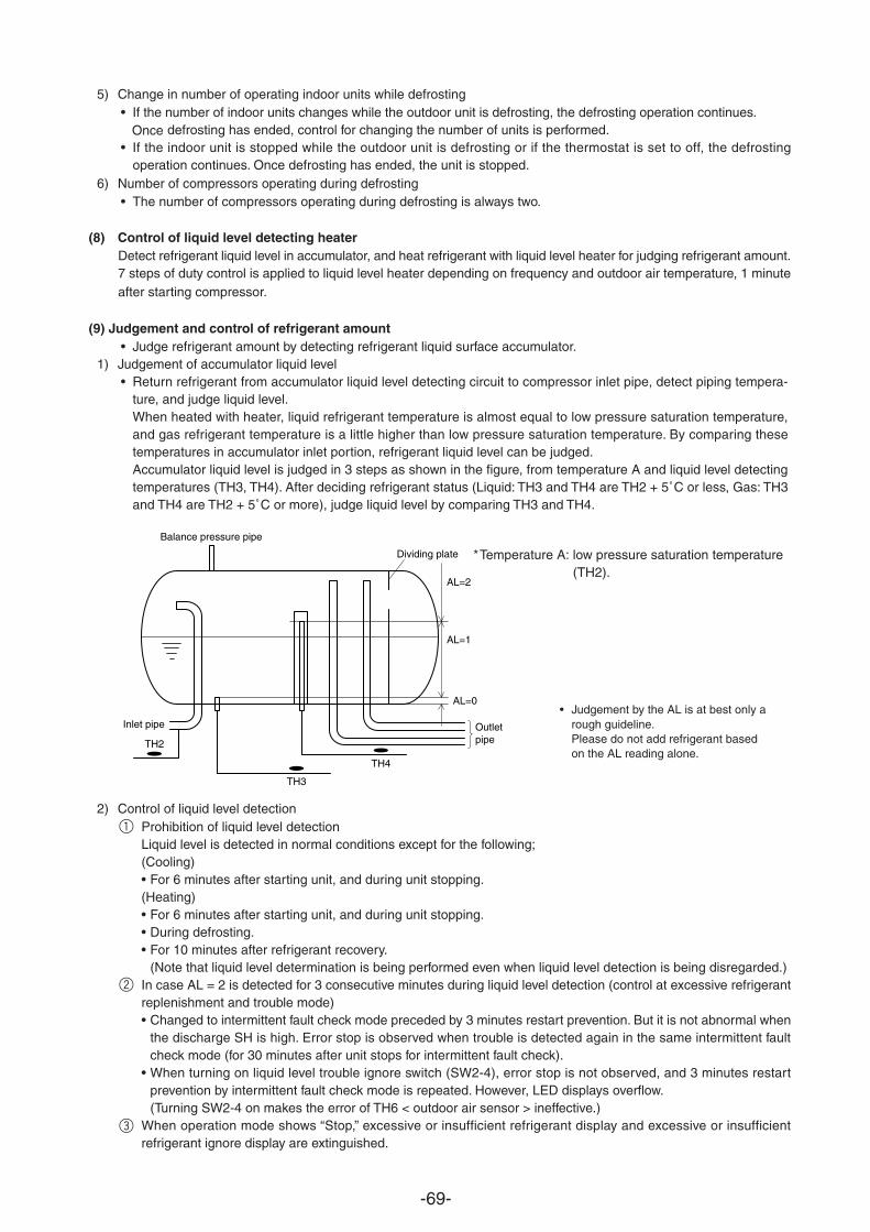
-69-
5) Change in number of operating indoor units while defrosting• If the number of indoor units changes while the outdoor unit is defrosting, the defrosting operation continues.
defrosting has ended, control for changing the number of units is performed.Once• If the indoor unit is stopped while the outdoor unit is defrosting or if the thermostat is set to off, the defrosting
operation continues. Once defrosting has ended, the unit is stopped.6) Number of compressors operating during defrosting
• The number of compressors operating during defrosting is always two.
(8) Control of liquid level detecting heaterDetect refrigerant liquid level in accumulator, and heat refrigerant with liquid level heater for judging refrigerant amount.7 steps of duty control is applied to liquid level heater depending on frequency and outdoor air temperature, 1 minuteafter starting compressor.
(9) Judgement and control of refrigerant amount• Judge refrigerant amount by detecting refrigerant liquid surface accumulator.
1) Judgement of accumulator liquid level• Return refrigerant from accumulator liquid level detecting circuit to compressor inlet pipe, detect piping tempera-
ture, and judge liquid level.When heated with heater, liquid refrigerant temperature is almost equal to low pressure saturation temperature,and gas refrigerant temperature is a little higher than low pressure saturation temperature. By comparing thesetemperatures in accumulator inlet portion, refrigerant liquid level can be judged.Accumulator liquid level is judged in 3 steps as shown in the figure, from temperature A and liquid level detectingtemperatures (TH3, TH4). After deciding refrigerant status (Liquid: TH3 and TH4 are TH2 + 5˚C or less, Gas: TH3and TH4 are TH2 + 5˚C or more), judge liquid level by comparing TH3 and TH4.
2) Control of liquid level detectionProhibition of liquid level detectionLiquid level is detected in normal conditions except for the following;(Cooling)• For 6 minutes after starting unit, and during unit stopping.(Heating)• For 6 minutes after starting unit, and during unit stopping.• During defrosting.• For 10 minutes after refrigerant recovery.
(Note that liquid level determination is being performed even when liquid level detection is being disregarded.)In case AL = 2 is detected for 3 consecutive minutes during liquid level detection (control at excessive refrigerantreplenishment and trouble mode)• Changed to intermittent fault check mode preceded by 3 minutes restart prevention. But it is not abnormal when
the discharge SH is high. Error stop is observed when trouble is detected again in the same intermittent faultcheck mode (for 30 minutes after unit stops for intermittent fault check).
• When turning on liquid level trouble ignore switch (SW2-4), error stop is not observed, and 3 minutes restartprevention by intermittent fault check mode is repeated. However, LED displays overflow.(Turning SW2-4 on makes the error of TH6 < outdoor air sensor > ineffective.)
When operation mode shows “Stop,” excessive or insufficient refrigerant display and excessive or insufficientrefrigerant ignore display are extinguished.
TH3
TH4
Balance pressure pipe
TH2
AL=0
AL=1
AL=2
Dividing plate
Outletpipe
Inlet pipe• Judgement by the AL is at best only a
rough guideline.Please do not add refrigerant basedon the AL reading alone.
*Temperature A: low pressure saturation (TH2).
temperature
1
2
3
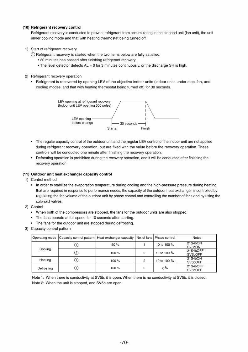
-70-
(10) Refrigerant recovery controlRefrigerant recovery is conducted to prevent refrigerant from accumulating in the stopped unit (fan unit), the unit
cooling mode and that with heating thermostat being turned off.
1) Start of refrigerant recoveryRefrigerant recovery is started when the two items below are fully satisfied.
• 30 minutes has passed after finishing refrigerant recovery.• The level detector detects AL = 0 for 3 minutes continuously, or the discharge SH is high.
2) Refrigerant recovery operation• Refrigerant is recovered by opening LEV of the objective indoor units (indoor units under stop. fan, and
modes, and that with heating thermostat being turned off) for 30 seconds.
• The regular capacity control of the outdoor unit and the regular LEV control of the indoor unit are not applied refrigerant recovery operation, but are fixed with the value before the recovery operation. These
conducted one minute after finishing the recovery operation.controls will be
• Defrosting operation is prohibited during the recovery operation, and it will be conducted after finishing the operation
(11) Outdoor unit heat exchanger capacity control1) Control method
• In order to stabilize the evaporation temperature during cooling and the high-pressure pressure during heating
are required in response to performance needs, the capacity of the outdoor heat exchanger is controlled by the fan volume of the outdoor unit by phase control and controlling the number of fans and by using the
valves.
2) Control• When both of the compressors are stopped, the fans for the outdoor units are also stopped.• The fans operate at full speed for 10 seconds after starting.
• The fans for the outdoor unit are stopped during defrosting.3) Capacity control pattern
Note 1: When there is conductivity at SV5b, it is open. When there is no conductivity at SV5b, it is closed.Note 2: When the unit is stopped, and SV5b are open.
Starts
LEV openingbefore change
LEV opening at refrigerant recovery(Indoor unit LEV opening 500 pulse)
Finish30 seconds
Operating mode Capacity control pattern Heat exchanger capacity No. of fans Phase control Notes
50 % 1 10 to 100 %
100 % 2 10 to 100 %
100 % 2 10 to 100 %
100 % 0 0 %
Cooling
Heating
Defrosting
21S4bONSV5bON21S4bOFFSV5bOFF21S4bONSV5bOFF21S4bOFFSV5bOFF
under
cooling
during
recovery
thatregulating
solenoid
1
1
1
1
2
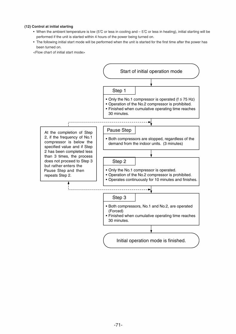
-71-
(12) Control at initial starting• When the ambient temperature is low (5˚C or less in cooling and – 5˚C or less in heating), initial starting will be
performed if the unit is started within 4 hours of the power being turned on.
• The following initial start mode will be performed when the unit is started for the first time after the power hasbeen turned on.
<Flow chart of initial start mode>
Start of initial operation mode
Initial operation mode is finished.
Step 1
•••
Only the No.1 compressor is operated (f 75 Hz)Operation of the No.2 compressor is prohibited.Finished when cumulative operating time reaches 30 minutes.
Pause Step
• Both compressors are stopped, regardless of thedemand from the indoor units. (3 minutes)
Step 2
•••
Only the No.1 compressor is operated. Operation of the No.2 compressor is prohibited.Operates continuously for 10 minutes and finishes.
Step 3
•
•
Both compressors, No.1 and No.2, are operated (Forced)Finished when cumulative operating time reaches 30 minutes.
At the completion of Step 2, if the frequency of No.1 compressor is below the specified value and if Step 2 has been completed less than 3 times, the process does not proceed to Step 3 but rather enters the Pause Step and then repeats Step 2.
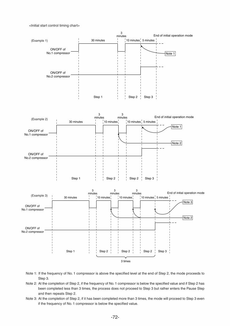
-72-
<Initial start control timing chart>
Note 1: If the frequency of No. 1 compressor is above the specified level at the end of Step 2, the mode proceeds to
Step 3.Note 2: At the completion of Step 2, if the frequency of No. 1 compressor is below the specified value and if Step 2 has
been completed less than 3 times, the process does not proceed to Step 3 but rather enters the Pause Step
and then repeats Step 2.Note 3: At the completion of Step 2, if it has been completed more than 3 times, the mode will proceed to Step 3 even
if the frequency of No. 1 compressor is below the specified value.
30 minutes
Step 1
3minutes
10 minutes
Step 2
5 minutes
Step 3
ON/OFF of No.1 compressor
ON/OFF of No.2 compressor
End of initial operation mode
Note 1
30 minutes
Step 1
3minutes
10 minutes
Step 2
3minutes
10 minutes
Step 2
5 minutes
Step 3
Note 1ON/OFF of
No.1 compressor
ON/OFF of No.2 compressor
Note 2
End of initial operation mode
30 minutes
Step 1
3minutes
10 minutes
Step 2
3minutes
10 minutes
Step 2
3 times
3minutes
10 minutes
Step 2
5 minutes
Step 3
Note 3ON/OFF of
No.1 compressor
ON/OFF of No.2 compressor
Note 2
End of initial operation mode
(Example 1)
(Example 2)
(Example 3)
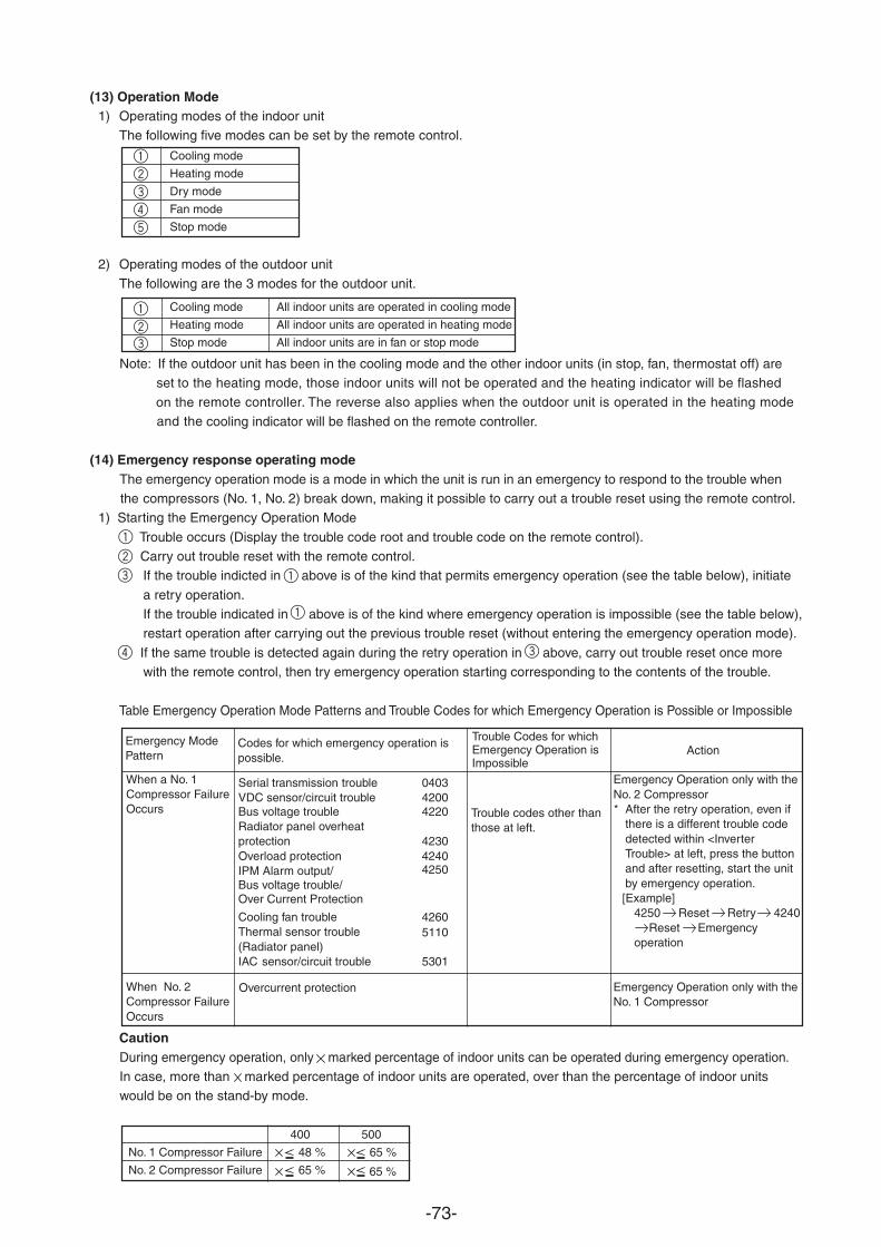
-73-
(13) Operation Mode1) Operating modes of the indoor unit
The following five modes can be set by the remote control.
Cooling mode
Heating mode
Dry mode
Fan mode
Stop mode
2) Operating modes of the outdoor unit
The following are the 3 modes for the outdoor unit.
Cooling mode All indoor units are operated in cooling mode
Heating mode All indoor units are operated in heating mode
Stop mode All indoor units are in fan or stop mode
Note: If the outdoor unit has been in the cooling mode and the other indoor units (in stop, fan, thermostat off) are to the heating mode, those indoor units will not be operated and the heating indicator will be flashed
remote controller. The reverse also applies when the outdoor unit is operated in the heating mode on thecooling indicator will be flashed on the remote controller.
(14) Emergency response operating modeThe emergency operation mode is a mode in which the unit is run in an emergency to respond to the trouble when
compressors (No. 1, No. 2) break down, making it possible to carry out a trouble reset using the remote control.the1) Starting the Emergency Operation Mode
Trouble occurs (Display the trouble code root and trouble code on the remote control). Carry out trouble reset with the remote control.
If the trouble indicted in above is of the kind that permits emergency operation (see the table below), initiate
y operation.If the trouble indicated in above is of the kind where emergency operation is impossible (see the table below),restart operation after carrying out the previous trouble reset (without entering the emergency operation mode).
If the same trouble is detected again during the retry operation in above, carry out trouble reset once morewith the remote control, then try emergency operation starting corresponding to the contents of the trouble.
Table Emergency Operation Mode Patterns and Trouble Codes for which Emergency Operation is Possible or Impossible
CautionDuring emergency operation, only marked percentage of indoor units can be operated during emergency operation.In case, more than marked percentage of indoor units are operated, over than the percentage of indoor unitswould be on the stand-by mode.
Codes for which emergency operation ispossible.
Emergency ModePattern
Trouble Codes for whichEmergency Operation isImpossible
Action
When a No. 1Compressor FailureOccurs
When No. 2Compressor FailureOccurs
Trouble codes other thanthose at left.
Emergency Operation only with theNo. 2 Compressor * After the retry operation, even if
there is a different trouble codedetected within <InverterTrouble> at left, press the buttonand after resetting, start the unitby emergency operation.[Example]
4250 Reset Retry 4240Reset Emergency
operation
Emergency Operation only with theNo. 1 Compressor
Overcurrent protection
400 500
No. 1 Compressor Failure 48 % 65 %
No. 2 Compressor Failure 65 % 65 %
set
and the
a retr
Serial transmission trouble 0403VDC sensor/circuit trouble 4200Bus voltage trouble 4220Radiator panel overheatprotection 4230Overload protection 4240
4250IPM Alarm output/Bus voltage trouble/Over Current Protection
Cooling fan trouble 4260Thermal sensor trouble(Radiator panel)
5110
IAC sensor/circuit trouble 5301
1
1
2
2
3
3
1
1
1
3
2
3
4
45
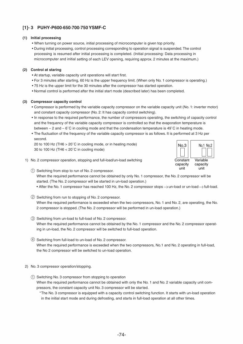
-74-
[1]- 3 PUHY-P600·650·700·750 YSMF-C
(1) Initial processing• When turning on power source, initial processing of microcomputer is given top priority.• During initial processing, control processing corresponding to operation signal is suspended. The control
is resumed after initial processing is completed. (Initial processing: Data processing in
setting of each LEV opening, requiring approx. 2 minutes at the maximum.)microcomputer and initial
(2) Control at staring• At startup, variable capacity unit operations will start first.• For 3 minutes after starting, 60 Hz is the upper frequency limit. (When only No. 1 compressor is operating.)• 75 Hz is the upper limit for the 30 minutes after the compressor has started operation.
• Normal control is performed after the initial start mode (described later) has been completed.
(3) Compressor capacity control• Compressor is performed by the variable capacity compressor on the variable capacity unit (No. 1: inverter motor)
and constant capacity compressor (No. 2: It has capacity control switching).• In response to the required performance, the number of compressors operating, the switching of capacity control
and the frequency of the variable capacity compressor is controlled so that the evaporation temperature isbetween – 2 and – 6˚C in cooling mode and that the condensation temperature is 49˚C in heating mode.
• The fluctuation of the frequency of the variab
second.20 to 100 Hz (TH6 > 20˚C in cooling mode, or in heating mode)30 to 100 Hz (TH6 < 20˚C in cooling mode)
1) No. 2 compressor operation, stopping and full-load/un-load switching
Switching from stop to run of No. 2 compressor.When the required performance cannot be obtained by only No. 1 compressor, the No. 2 compressor will bestarted. (The No. 2 compressor will be started in un-load operation.)• After the No. 1 compressor has reached 100 Hz, the No. 2 compressor stops un-load or un-load full-load.
Switching from run to stopping of No. 2 compressor.When the required performance is exceeded when the two compressors, No. 1 and No. 2, are operating, the No.
2 compressor is stopped. (The No. 2 compressor will be performed in un-load operation.)
Switching from un-load to full-load of No. 2 compressor.
When the required performance cannot be obtained by the No. 1 compressor and the No. 2 compressor operat-ing in un-load, the No. 2 compressor will be switched to full-load operation.
Switching from full-load to un-load of No. 2 compressor.When the required performance is exceeded when the two compressors, No.1 and No. 2 operating in full-load,the No 2 compressor will be switched to un-load operation.
2) No. 3 compressor operation/stopping.
Switching No. 3 compressor from stopping to operationWhen the required performance cannot be obtained with only the No. 1 and No. 2 variable capacity unit com-
pressors, the constant capacity unit No. 3 compressor will be started.*The No. 3 compressor is equipped with a capacity control switching function. It starts with un-load operationin the initial start mode and during defrosting, and starts in full-load operation at all other times.
No.3 No.1 No.2
Constantcapacity
unit
Variablecapacity
unit
processing
1
2
3
4
1
le capacity compressor is as follows. It is performed at 3 Hz per
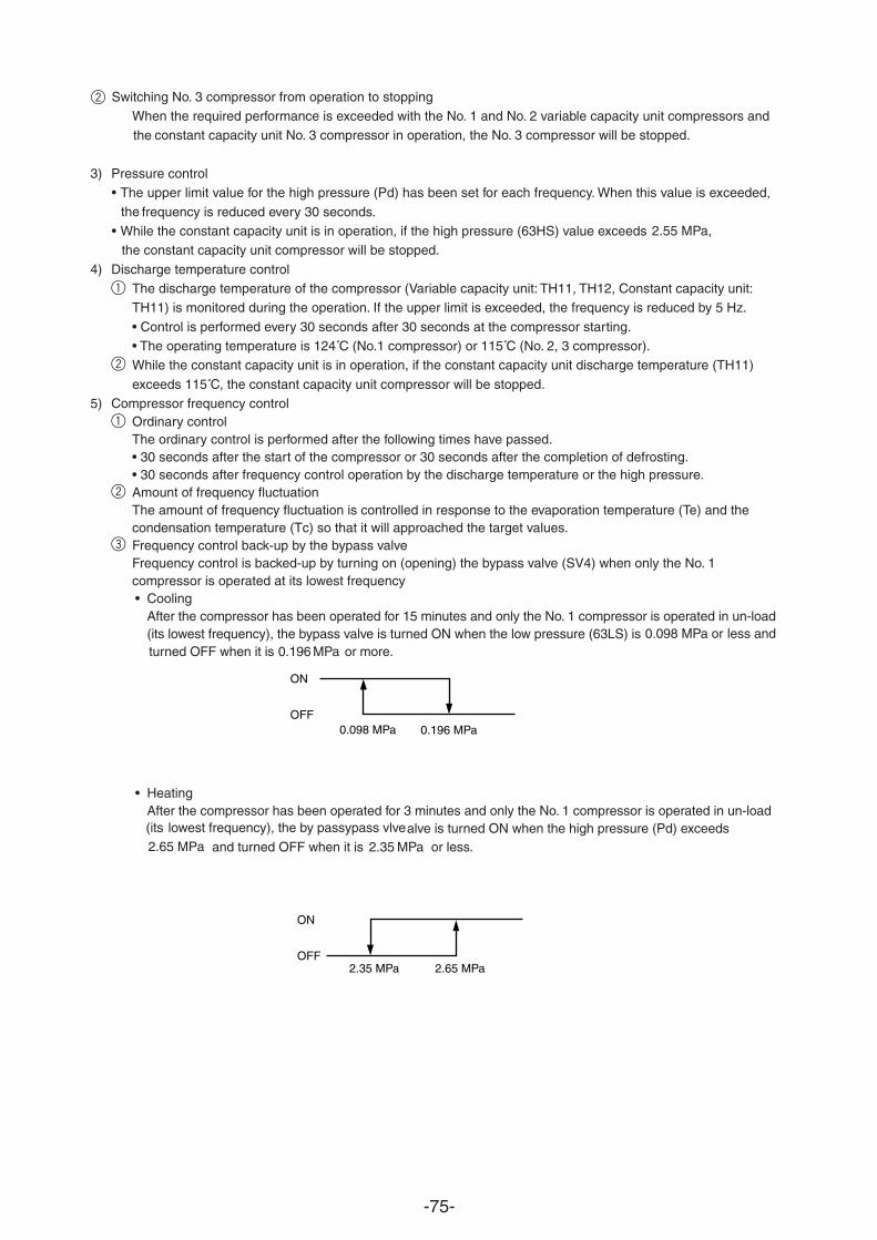
-75-
Switching No. 3 compressor from operation to stoppingWhen the required performance is exceeded with the No. 1 and No. 2 variable capacity unit compressors and
constant capacity unit No. 3 compressor in operation, the No. 3 compressor will be stopped.
3) Pressure control• The upper limit value for the high pressure (Pd) has been set for each frequency. When this value is exceeded,
frequency is reduced every 30 seconds.• While the constant capacity unit is in operation, if the high pressure (63HS) value exceeds
the constant capacity unit compressor will be stopped.
2.55 MPa,
4) Discharge temperature controlThe discharge temperature of the compressor (Variable capacity unit: TH11, TH12, Constant capacity unit:TH11) is monitored during the operation. If the upper limit is exceeded, the frequency is reduced by 5 Hz.
• Control is performed every 30 seconds after 30 seconds at the compressor starting.• The operating temperature is 124˚C (No.1 compressor) or 115˚C (No. 2, 3 compressor).While the constant capacity unit is in operation, if the constant capacity unit discharge temperature (TH11)
exceeds 115˚C, the constant capacity unit compressor will be stopped.5) Compressor frequency control
Ordinary controlThe ordinary control is performed after the following times have passed.• 30 seconds after the start of the compressor or 30 seconds after the completion of defrosting.• 30 seconds after frequency control operation by the discharge temperature or the high pressure.Amount of frequency fluctuationThe amount of frequency fluctuation is controlled in response to the evaporation temperature (Te) and thecondensation temperature (Tc) so that it will approached the target values.Frequency control back-up by the bypass valveFrequency control is backed-up bcompressor is operated at its lowest frequency.• Cooling
After the compressor has been operated for 15 minutes and only the No. 1 compressor is operated in un-load(its lowest frequency), the bypass valve is turned ON when the low pressure (63LS) is or less and turned OFF when it is 0.196 MPa or more.
0.098 MPa
• HeatingAfter the compressor has been operated for 3 minutes and only the No. 1 compressor is operated in un-load
alve is turned ON when the high pressure (Pd) exceeds and turned OFF when it is 2.35 MPa or less.
ON
OFF0.098 MPa 0.196 MPa
ON
OFF2.35 MPa 2.65 MPa
the
the
lowest frequency), the by passypass vlve(its2.65 MPa
2
1
1
2
2
3
y turning on (opening) the bypass valve (SV4) when only the No. 1
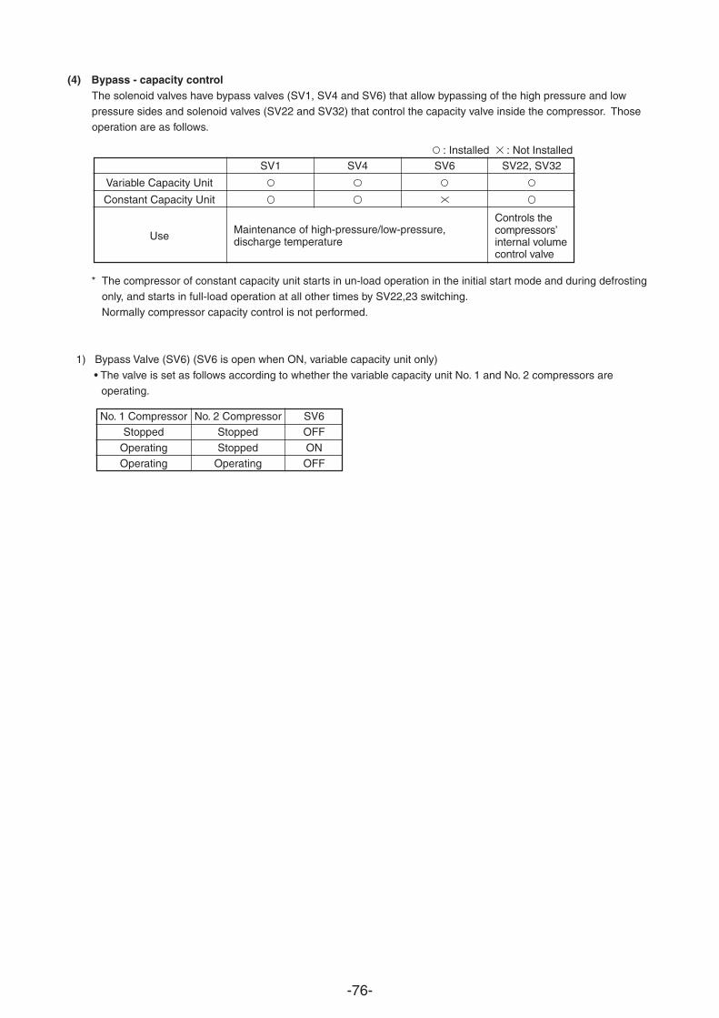
-76-
(4) Bypass - capacity controlThe solenoid valves have bypass valves (SV1, SV4 and SV6) that allow bypassing of the high pressure and lowpressure sides and solenoid valves (SV22 and SV32) that control the capacity valve inside the compressor. Thoseoperation are as follows.
: Installed : Not InstalledSV1 SV4 SV6 SV22, SV32
Variable Capacity Unit
Constant Capacity Unit
Use
* The compressor of constant capacity unit starts in un-load operation in the initial start mode and during defrostingonly, and starts in full-load operation at all other times by SV22,23 switching.Normally compressor capacity control is not performed.
1) Bypass Valve (SV6) (SV6 is open when ON, variable capacity unit only)
• The valve is set as follows according to whether the variable capacity unit No. 1 and No. 2 compressors areoperating.
No. 1 Compressor No. 2 Compressor SV6Stopped Stopped OFF
Operating Stopped ONOperating Operating OFF
Maintenance of high-pressure/low-pressure,discharge temperature
Controls thecompressors’internal volumecontrol valve
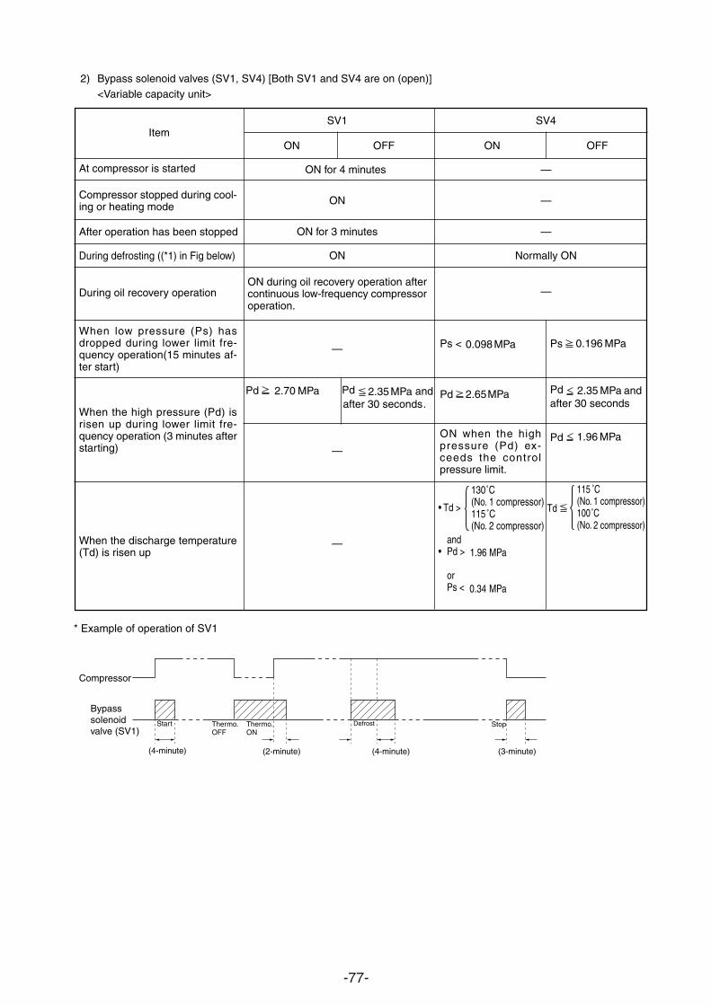
-77-
130˚C(No. 1 compressor)115˚C(No. 2 compressor)
• Td >
SV1
ON OFF
ON for 4 minutes
ON
ON for 3 minutes
ON
ON during oil recovery operation aftercontinuous low-frequency compressoroperation.
—
—
—
Item
At compressor is started
Compressor stopped during cool-ing or heating mode
After operation has been stopped
During defrosting ((*1) in Fig below)
During oil recovery operation
When low pressure (Ps) hasdropped during lower limit fre-quency operation(15 minutes af-ter start)
When the high pressure (Pd) isrisen up during lower limit fre-quency operation (3 minutes afterstarting)
When the discharge temperature(Td) is risen up
Ps 0.196 MPa
Pd 2.35 MPa andafter 30 seconds
Pd 1.96 MPa
* Example of operation of SV1
Compressor
Bypasssolenoidvalve (SV1)
(4-minute) (2-minute) (4-minute) (3-minute)
Start Thermo.OFF
Thermo.ON
Defrost Stop
2) Bypass solenoid valves (SV1, SV4) [Both SV1 and SV4 are on (open)]<Variable capacity unit>
Ps < 0.098 MPa
Pd 2.65 MPa
ON when the highpressure (Pd) ex-ceeds the controlpressure limit.
SV4
ON OFF
—
—
—
Normally ON
—
Pd 2.70 MPa Pd 2.35 MPa andafter 30 seconds.
and• Pd > 1.96 MPa
orPs < 0.34 MPa
115 ˚C(No. 1 compressor)100˚C(No. 2 compressor)
Td
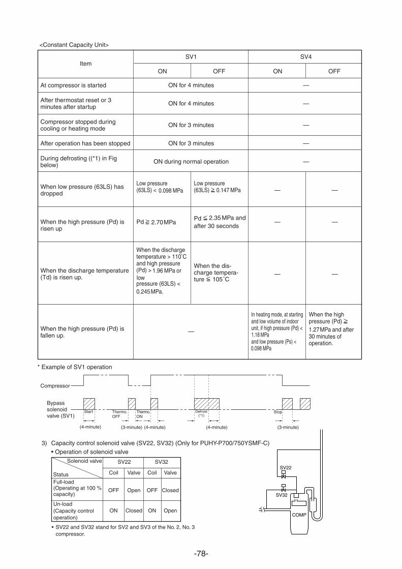
-78-
Item
At compressor is started
After thermostat reset or 3minutes after startup
Compressor stopped duringcooling or heating mode
After operation has been stopped
During defrosting ((*1) in Figbelow)
When low pressure (63LS) hasdropped
When the high pressure (Pd) isrisen up
When the discharge temperature(Td) is risen up.
When the high pressure (Pd) isfallen up.
* Example of SV1 operation
Compressor
Bypasssolenoidvalve (SV1)
(4-minute) (3-minute) (4-minute) (3-minute)
Start Thermo.OFF
Thermo.ON
Defrost(*1)
Stop
<Constant Capacity Unit>
SV1
ON for 4 minutes
ON for 4 minutes
ON for 3 minutes
ON for 3 minutes
ON during normal operation
—
SV4
—
—
—
—
—
3) Capacity control solenoid valve (SV22, SV32) (Only for PUHY-P700/750YSMF-C)• Operation of solenoid valve
• SV22 and SV32 stand for SV2 and SV3 of the No. 2, No. 3compressor.
Solenoid valveSV22
SV32
COMP
SV22 SV32
Coil Valve Coil Valve
OFF Open OFF Closed
ON Closed ON Open
StatusFull-load(Operating at 100 %capacity)
Un-load(Capacity controloperation)
ON OFF
Low pressure(63LS) < 0.098 MPa
Pd 2.70 MPa
When the dischargetemperature > 110˚Cand high pressure(Pd) > 1.96 MPa or lowpressure (63LS) <0.245 MPa.
Low pressure(63LS) 0.147 MPa
Pd 2.35 MPa andafter 30 seconds
When the dis-charge tempera-ture 105˚C
—
—
—
In heating mode, at startingand low volume of indoorunit, if high pressure (Pd) <1.18 MPaand low pressure (Ps) <0.098 MPa
—
—
—
When the highpressure (Pd) 1.27 MPa and after30 minutes ofoperation.
(4-minute)
ON OFF
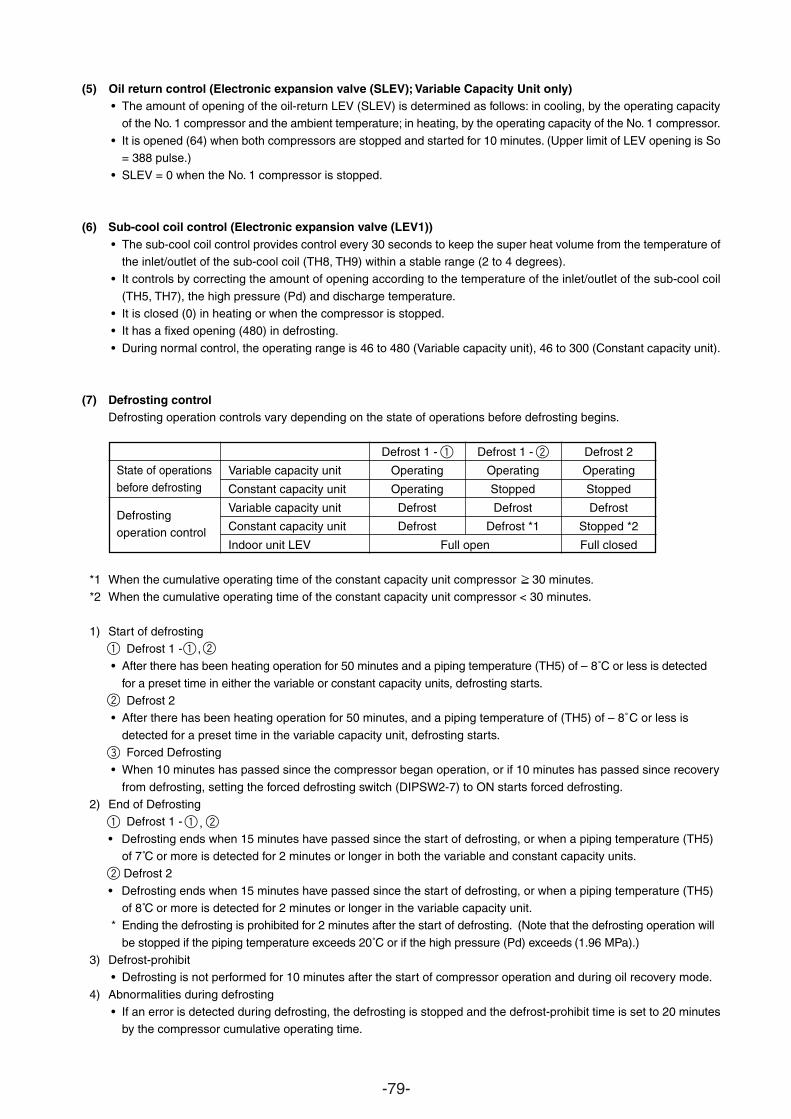
-79-
(5) Oil return control (Electronic expansion valve (SLEV); Variable Capacity Unit only)• The amount of opening of the oil-return LEV (SLEV) is determined as follows: in cooling, by the operating capacity
of the No. 1 compressor and the ambient temperature; in heating, by the operating capacity of the No. 1 compressor.
• It is opened (64) when both compressors are stopped and started for 10 minutes. (Upper limit of LEV opening is So= 388 pulse.)
• SLEV = 0 when the No. 1 compressor is stopped.
(6) Sub-cool coil control (Electronic expansion valve (LEV1))• The sub-cool coil control provides control every 30 seconds to keep the super heat volume from the temperature of
the inlet/outlet of the sub-cool coil (TH8, TH9) within a stable range (2 to 4 degrees).• It controls by correcting the amount of opening according to the temperature of the inlet/outlet of the sub-cool coil
(TH5, TH7), the high pressure (Pd) and discharge temperature.• It is closed (0) in heating or when the compressor is stopped.• It has a fixed opening (480) in defrosting.
• During normal control, the operating range is 46 to 480 (Variable capacity unit), 46 to 300 (Constant capacity unit).
(7) Defrosting controlDefrosting operation controls vary depending on the state of operations before defrosting begins.
Defrost 1 - Defrost 1 - Defrost 2
Variable capacity unit Operating Operating Operating
Constant capacity unit Operating Stopped Stopped
Variable capacity unit Defrost Defrost Defrost
Constant capacity unit Defrost Defrost *1 Stopped *2
Indoor unit LEV Full open Full closed
*1 When the cumulative operating time of the constant capacity unit compressor 30 minutes.*2 When the cumulative operating time of the constant capacity unit compressor < 30 minutes.
1) Start of defrosting Defrost 1 - ,
• After there has been heating operation for 50 minutes and a piping temperature (TH5) of – 8˚C or less is detected
for a preset time in either the variable or constant capacity units, defrosting starts. Defrost 2
• After there has been heating operation for 50 minutes, and a piping temperature of (TH5) of – 8˚C or less is
detected for a preset time in the variable capacity unit, defrosting starts. Forced Defrosting
• When 10 minutes has passed since the compressor began operation, or if 10 minutes has passed since recovery
from defrosting, setting the forced defrosting switch (DIPSW2-7) to ON starts forced defrosting.2) End of Defrosting
Defrost 1 - , • Defrosting ends when 15 minutes have passed since the start of defrosting, or when a piping temperature (TH5)
of 7˚C or more is detected for 2 minutes or longer in both the variable and constant capacity units. Defrost 2
• Defrosting ends when 15 minutes have passed since the start of defrosting, or when a piping temperature (TH5)of 8˚C or more is detected for 2 minutes or longer in the variable capacity unit.
* Ending the defrosting is prohibited for 2 minutes after the start of defrosting. (Note that the defrosting operation will
be stopped if the piping temperature exceeds 20˚C or if the high pressure (Pd) exceeds (1.96 MPa).)3) Defrost-prohibit
• Defrosting is not performed for 10 minutes after the start of compressor operation and during oil recovery mode.
4) Abnormalities during defrosting• If an error is detected during defrosting, the defrosting is stopped and the defrost-prohibit time is set to 20 minutes
by the compressor cumulative operating time.
State of operationsbefore defrosting
Defrostingoperation control
1
1 1
1 1 2
2
2
2
3
2
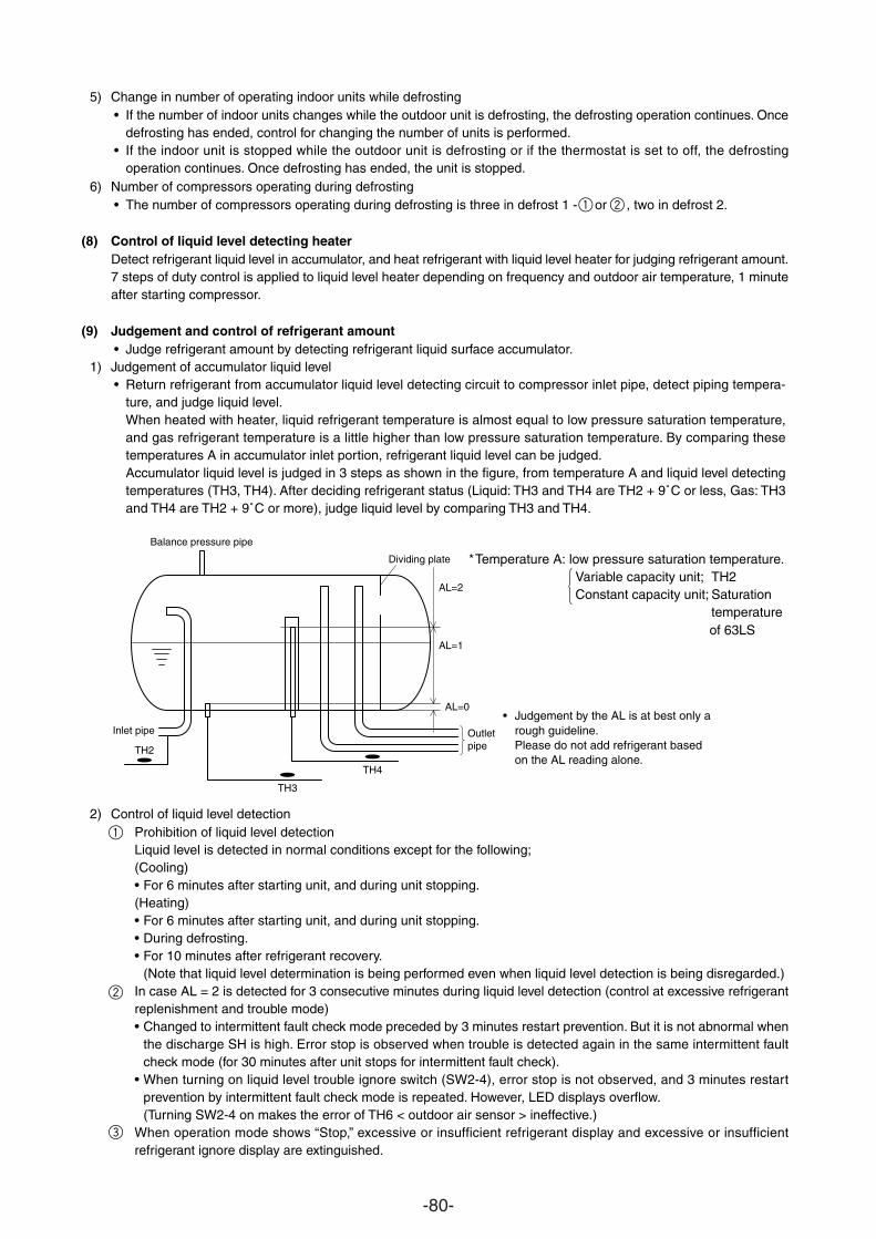
-80-
5) Change in number of operating indoor units while defrosting• If the number of indoor units changes while the outdoor unit is defrosting, the defrosting operation continues. Once
defrosting has ended, control for changing the number of units is performed.• If the indoor unit is stopped while the outdoor unit is defrosting or if the thermostat is set to off, the defrosting
operation continues. Once defrosting has ended, the unit is stopped.6) Number of compressors operating during defrosting
• The number of compressors operating during defrosting is three in defrost 1 - or , two in defrost 2.
(8) Control of liquid level detecting heaterDetect refrigerant liquid level in accumulator, and heat refrigerant with liquid level heater for judging refrigerant amount.7 steps of duty control is applied to liquid level heater depending on frequency and outdoor air temperature, 1 minuteafter starting compressor.
(9) Judgement and control of refrigerant amount• Judge refrigerant amount by detecting refrigerant liquid surface accumulator.
1) Judgement of accumulator liquid level• Return refrigerant from accumulator liquid level detecting circuit to compressor inlet pipe, detect piping tempera-
ture, and judge liquid level.When heated with heater, liquid refrigerant temperature is almost equal to low pressure saturation temperature,and gas refrigerant temperature is a little higher than low pressure saturation temperature. By comparing thesetemperatures A in accumulator inlet portion, refrigerant liquid level can be judged.Accumulator liquid level is judged in 3 steps as shown in the figure, from temperature A and liquid level detectingtemperatures (TH3, TH4). After deciding refrigerant status (Liquid: TH3 and TH4 are TH2 + 9˚C or less, Gas: TH3and TH4 are TH2 + 9˚C or more), judge liquid level by comparing TH3 and TH4.
2) Control of liquid level detectionProhibition of liquid level detectionLiquid level is detected in normal conditions except for the following;(Cooling)• For 6 minutes after starting unit, and during unit stopping.(Heating)• For 6 minutes after starting unit, and during unit stopping.• During defrosting.• For 10 minutes after refrigerant recovery.
(Note that liquid level determination is being performed even when liquid level detection is being disregarded.)In case AL = 2 is detected for 3 consecutive minutes during liquid level detection (control at excessive refrigerantreplenishment and trouble mode)• Changed to intermittent fault check mode preceded by 3 minutes restart prevention. But it is not abnormal when
the discharge SH is high. Error stop is observed when trouble is detected again in the same intermittent faultcheck mode (for 30 minutes after unit stops for intermittent fault check).
• When turning on liquid level trouble ignore switch (SW2-4), error stop is not observed, and 3 minutes restartprevention by intermittent fault check mode is repeated. However, LED displays overflow.(Turning SW2-4 on makes the error of TH6 < outdoor air sensor > ineffective.)
When operation mode shows “Stop,” excessive or insufficient refrigerant display and excessive or insufficientrefrigerant ignore display are extinguished.
TH3
TH4
Balance pressure pipe
TH2
AL=0
AL=1
AL=2
Dividing plate
Outletpipe
Inlet pipe• Judgement by the AL is at best only a
rough guideline.Please do not add refrigerant basedon the AL reading alone.
*Temperature A: low pressure saturation temperature.Variable capacity unit; TH2Constant capacity unit; Saturation
temperatureof 63LS
1
1
2
3
2
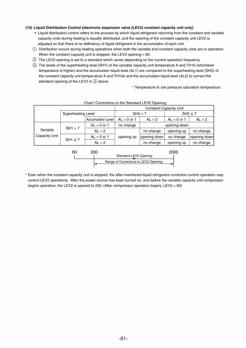
-81-
(10) Liquid Distribution Control (electronic expansion valve (LEV2) constant capacity unit only)• Liquid distribution control refers to the process by which liquid refrigerant returning from the constant and variable
capacity units during heating is equally distributed, and the opening of the constant capacity unit LEV2 is
so that there is no deficiency of liquid refrigerant in the accumulator of each unit.adjustedDistribution occurs during heating operations when both the variable and constant capacity units are in operation.When the constant capacity unit is stopped, the LEV2 opening = 60.
The LEV2 opening is set to a standard which varies depending on the current operation frequency.The levels of the superheating level (SH1) of the variable capacity unit temperature A and TH10 (whichevertemperature is higher) and the accumulator liquid level (AL1) are compared to the superheating level (SH2) of
ature A and TH10a and the accumulator liquid level (AL2) to correct the above.
Chart: Corrections to the Standard LEV2 Opening
Constant Capacity UnitSuperheating Level SH2 > 7 SH2 7
Accumulator Level AL = 0 or 1 AL = 2 AL = 0 or 1 AL = 2
Variable SH1 > 7AL = 0 or 1 no change opening down
Capacity UnitAL = 2 no change opening up no change
SH1 7AL = 0 or 1 opening up opening down no change opening down
AL = 2 no change opening up no change
* Even when the constant capacity unit is stopped, the after-mentioned liquid refrigerant correction control operation may
control LEV2 operations. After the power source has been turned on, and before the variable capacity unit compressorbegins operation, the LEV2 is opened to 200. (After compressor operation begins, LEV2 = 60)
60 200 2000Standard LEV2 Opening
Range of Corrections to LEV2 Opening
* Temperature A: low pressure saturation temperature.
standard opening of the LEV2 in the constant capacity unit temper
1
2
2
3
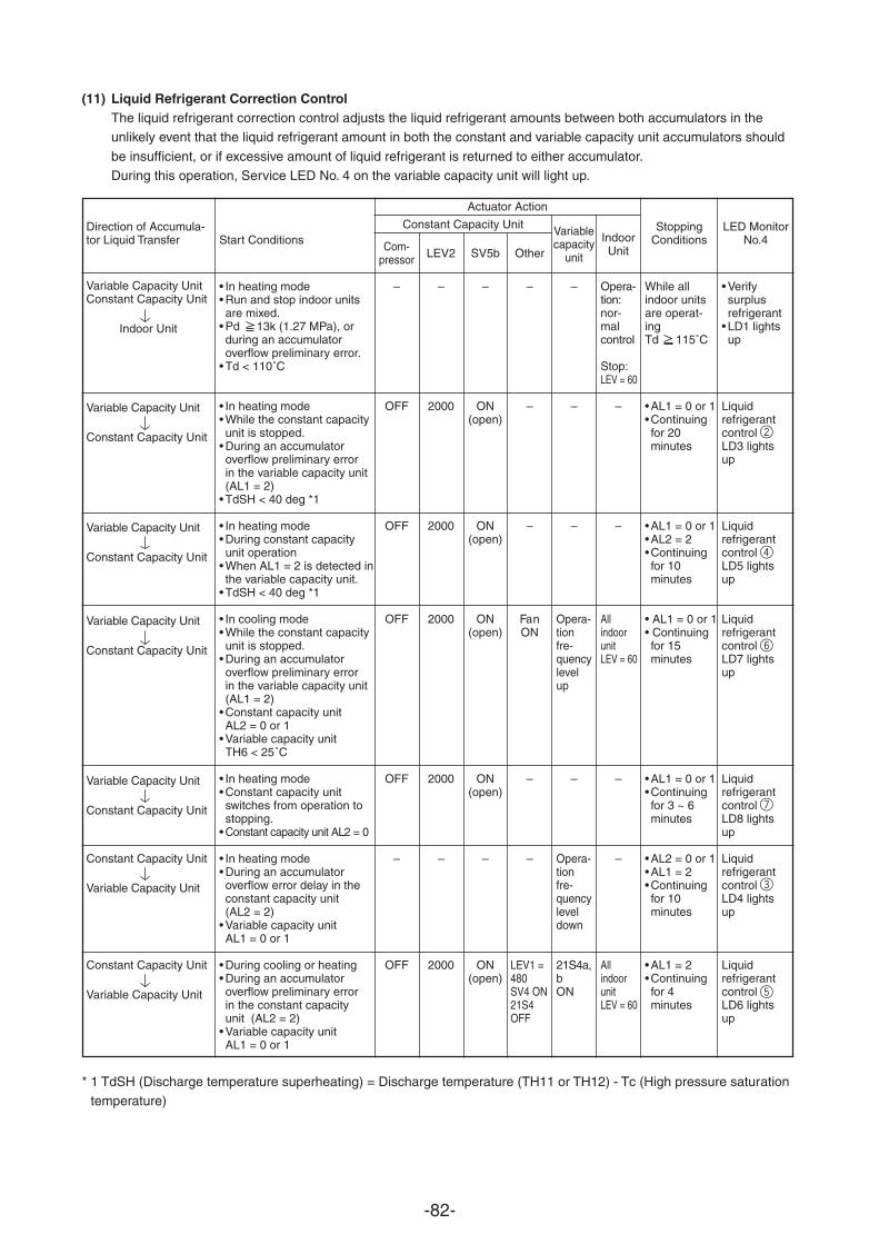
-82-
(11) Liquid Refrigerant Correction ControlThe liquid refrigerant correction control adjusts the liquid refrigerant amounts between both accumulators in theunlikely event that the liquid refrigerant amount in both the constant and variable capacity unit accumulators should
be insufficient, or if excessive amount of liquid refrigerant is returned to either accumulator.During this operation, Service LED No. 4 on the variable capacity unit will light up.
Direction of Accumula-tor Liquid Transfer
Variable Capacity UnitConstant Capacity Unit
Indoor Unit
Variable Capacity Unit
Constant Capacity Unit
Variable Capacity Unit
Constant Capacity Unit
Variable Capacity Unit
Constant Capacity Unit
Variable Capacity Unit
Constant Capacity Unit
Constant Capacity Unit
Variable Capacity Unit
Constant Capacity Unit
Variable Capacity Unit
Start Conditions
• In heating mode• Run and stop indoor unitsare mixed.
• Pd 13k (1.27 MPa), orduring an accumulatoroverflow preliminary error.
• Td < 110˚C
• In heating mode• While the constant capacityunit is stopped.
• During an accumulatoroverflow preliminary errorin the variable capacity unit(AL1 = 2)
• TdSH < 40 deg *1
• In heating mode• During constant capacityunit operation
• When AL1 = 2 is detected inthe variable capacity unit.
• TdSH < 40 deg *1
• In cooling mode• While the constant capacityunit is stopped.
• During an accumulatoroverflow preliminary errorin the variable capacity unit(AL1 = 2)
• Constant capacity unitAL2 = 0 or 1
• Variable capacity unitTH6 < 25˚C
• In heating mode• Constant capacity unitswitches from operation tostopping.
• Constant capacity unit AL2 = 0
• In heating mode• During an accumulatoroverflow error delay in theconstant capacity unit(AL2 = 2)
• Variable capacity unitAL1 = 0 or 1
• During cooling or heating• During an accumulatoroverflow preliminary errorin the constant capacityunit (AL2 = 2)
• Variable capacity unitAL1 = 0 or 1
Actuator Action
Com-pressor
–
OFF
OFF
OFF
OFF
–
OFF
Constant Capacity Unit Variablecapacity
unit
–
–
–
Opera-tionfre-quencylevelup
–
Opera-tionfre-quencyleveldown
21S4a,bON
IndoorUnit
Opera-tion:nor-malcontrol
Stop:LEV = 60
–
–
AllindoorunitLEV = 60
–
–
AllindoorunitLEV = 60
StoppingConditions
While allindoor unitsare operat-ingTd 115˚C
• AL1 = 0 or 1• Continuingfor 20minutes
• AL1 = 0 or 1• AL2 = 2• Continuingfor 10minutes
• AL1 = 0 or 1• Continuingfor 15minutes
• AL1 = 0 or 1• Continuingfor 3 ~ 6minutes
• AL2 = 0 or 1• AL1 = 2• Continuingfor 10minutes
• AL1 = 2• Continuingfor 4minutes
LED MonitorNo.4
• Verifysurplusrefrigerant
• LD1 lightsup
Liquidrefrigerantcontrol LD3 lightsup
Liquidrefrigerantcontrol LD5 lightsup
Liquidrefrigerantcontrol LD7 lightsup
Liquidrefrigerantcontrol LD8 lightsup
Liquidrefrigerantcontrol LD4 lightsup
Liquidrefrigerantcontrol LD6 lightsup
LEV2
–
2000
2000
2000
2000
–
2000
SV5b
–
ON(open)
ON(open)
ON(open)
ON(open)
–
ON(open)
Other
–
–
–
FanON
–
–
LEV1 =480SV4 ON21S4OFF
* 1 TdSH (Discharge temperature superheating) = Discharge temperature (TH11 or TH12) - Tc (High pressure saturation
temperature)
2
4
6
7
3
5
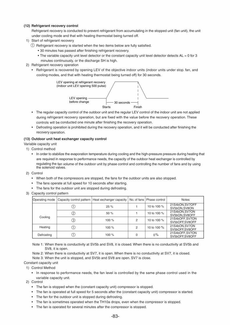
-83-
(12) Refrigerant recovery controlRefrigerant recovery is conducted to prevent refrigerant from accumulating in the stopped unit (fan unit), the unit
cooling mode and that with heating thermostat being turned off.under1) Start of refrigerant recovery
Refrigerant recovery is started when the two items below are fully satisfied.
• 30 minutes has passed after finishing refrigerant recovery.• The variable capacity unit level detector or the constant capacity unit level detector detects AL = 0 for 3
continuously, or the discharge SH is high.minutes2) Refrigerant recovery operation
• Refrigerant is recovered by opening LEV of the objective indoor units (indoor units under stop. fan, and
modes, and that with heating thermostat being turned off) for 30 seconds.cooling
• The regular capacity control of the outdoor unit and the regular LEV control of the indoor unit are not applied
refrigerant recovery operation, but are fixed with the value before the recovery operation. These conducted one minute after finishing the recovery operation.controls will be
• Defrosting operation is prohibited during the recovery operation, and it will be conducted after finishing the
operation.recovery
(13) Outdoor unit heat exchanger capacity controlVariable capacity unit
1) Control method• In order to stabilize the evaporation temperature during cooling and the high-pressure pressure during heating that
required in response to performance needs, the capacity of the outdoor heat exchanger is controlled byarefan volume of the outdoor unit by phase control and controlling the number of fans and by using regulating the
2) Control
• When both of the compressors are stopped, the fans for the outdoor units are also stopped.• The fans operate at full speed for 10 seconds after starting.• The fans for the outdoor unit are stopped during defrosting.
3) Capacity control pattern
Constant capacity unit1) Control Method
• In response to performance needs, the fan level is controlled by the same phase control used in the capacity unit.variable
2) Control
• The fan is stopped when the (constant capacity unit) compressor is stopped.• The fan is operated at full speed for 5 seconds after the (constant capacity unit) compressor is started.• The fan for the outdoor unit is stopped during defrosting.
• The fan is sometimes operated when the TH10a drops, even when the compressor is stopped.• The fan is operated for several minutes after the compressor is stopped.
Note 1:
Note 2: When there is conductivity at SV7, it is open. When there is no conductivity at SV7, it is closed.Note 3: When the unit is stopped, and SV5b and SV8 are open. SV7 is close.
When there is conductivity at SV5b and SV8, it is closed. When there is no conductivity at SV5b and SV8, it is open.
Starts
LEV openingbefore change
LEV opening at refrigerant recovery(Indoor unit LEV opening 500 pulse)
Finish30 seconds
Operating mode Capacity control pattern Heat exchanger capacity No. of fans Phase control Notes
50 %
25 %
1
1
10 to 100 %
10 to 100 %
100 % 2 10 to 100 %
100 % 2 10 to 100 %
100 % 0 0 %
Cooling
Heating
Defrosting
21S4bON,SV7ONSV5bON,SV8OFF
21S4bON,SV7OFFSV5bON,SV8ON
21S4bOFF,SV7ONSV5bOFF,SV8OFF21S4bON,SV7ONSV5bOFF,SV8OFF21S4bOFF,SV7ONSV5bOFF,SV8OFF
during
the solenoid valves.
1
1
1
1
2
3
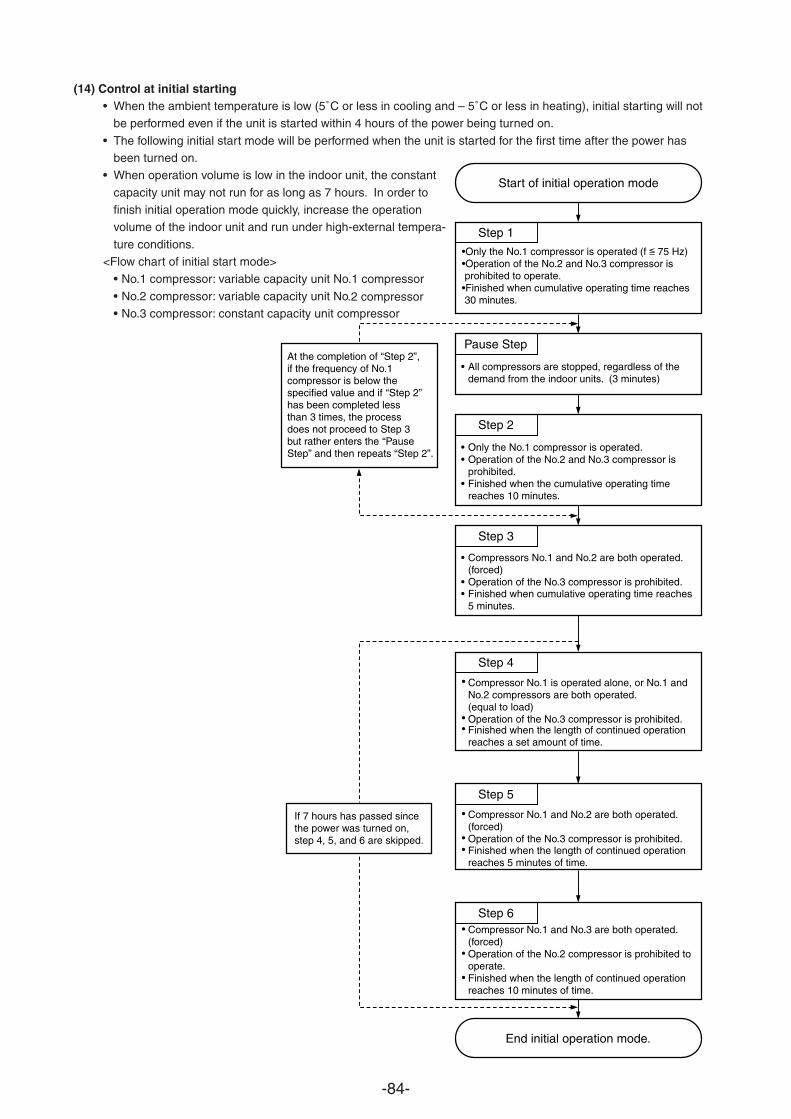
-84-
(14) Control at initial starting• When the ambient temperature is low (5˚C or less in cooling and – 5˚C or less in heating), initial starting will not
be performed even if the unit is started within 4 hours of the power being turned on.
• The following initial start mode will be performed when the unit is started for the first time after the power hasbeen turned on.
• When operation volume is low in the indoor unit, the constant
capacity unit may not run for as long as 7 hours. In order tofinish initial operation mode quickly, increase the operationvolume of the indoor unit and run under high-external tempera-
ture conditions.<Flow chart of initial start mode>
• No.1 compressor: variable capacity unit No.1 compressor
• No.2 compressor: variable capacity unit No.2 compressor• No.3 compressor: constant capacity unit compressor
Start of initial operation mode
End initial operation mode.
Step 1
•Only the No.1 compressor is operated (f 75 Hz)•Operation of the No.2 and No.3 compressor is prohibited to operate.•Finished when cumulative operating time reaches 30 minutes.
Pause Step
• All compressors are stopped, regardless of thedemand from the indoor units. (3 minutes)
Step 2
••
•
Only the No.1 compressor is operated. Operation of the No.2 and No.3 compressor isprohibited.Finished when the cumulative operating timereaches 10 minutes.
Step 3
Step 4
Step 5
Step 6
•
••
Compressors No.1 and No.2 are both operated. (forced)Operation of the No.3 compressor is prohibited.Finished when cumulative operating time reaches 5 minutes.
Compressor No.1 is operated alone, or No.1 andNo.2 compressors are both operated.(equal to load)Operation of the No.3 compressor is prohibited.Finished when the length of continued operationreaches a set amount of time.
•
••
•
••
•
•
•
If 7 hours has passed sincethe power was turned on,step 4, 5, and 6 are skipped.
At the completion of “Step 2”,if the frequency of No.1compressor is below thespecified value and if “Step 2”has been completed lessthan 3 times, the processdoes not proceed to Step 3but rather enters the “PauseStep” and then repeats “Step 2”.
Compressor No.1 and No.2 are both operated.(forced)Operation of the No.3 compressor is prohibited.Finished when the length of continued operationreaches 5 minutes of time.
Compressor No.1 and No.3 are both operated.(forced)Operation of the No.2 compressor is prohibited tooperate.Finished when the length of continued operationreaches 10 minutes of time.
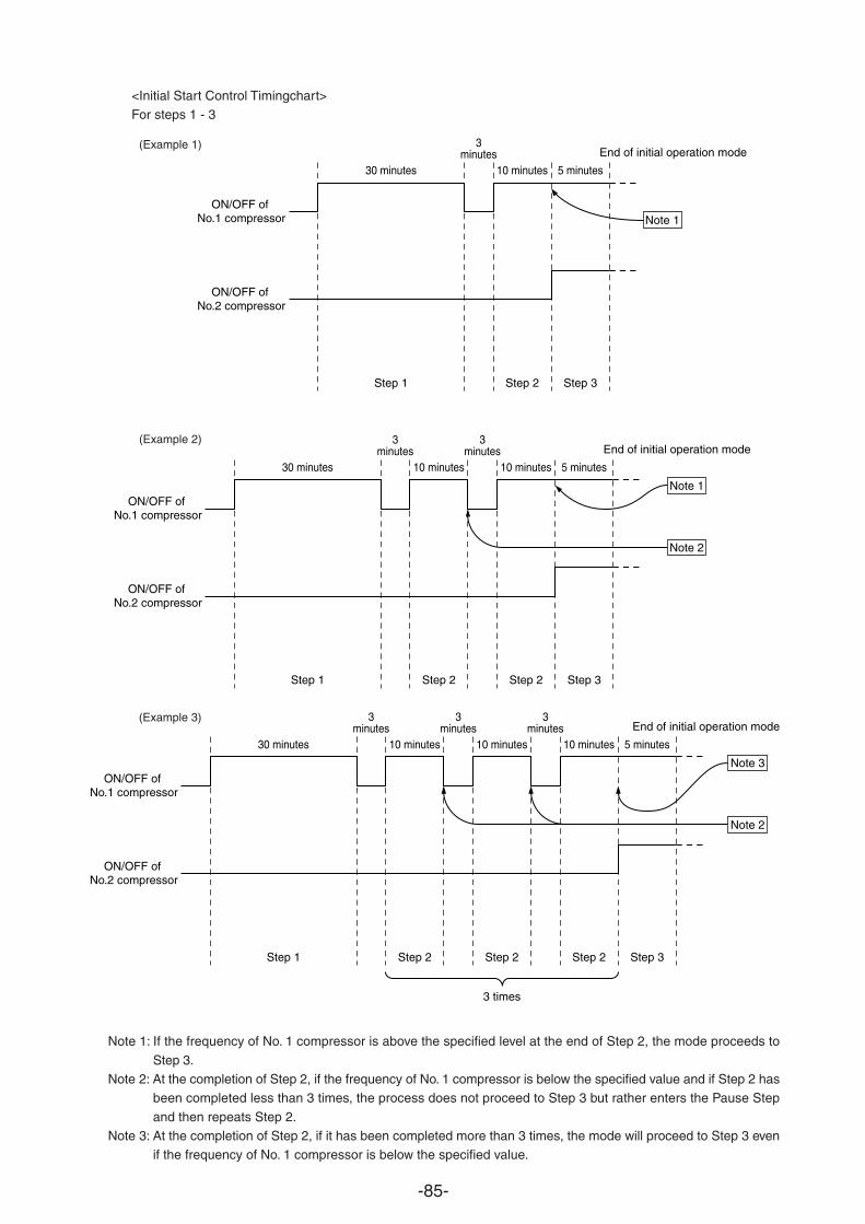
-85-
<Initial Start Control Timingchart>For steps 1 - 3
Note 1: If the frequency of No. 1 compressor is above the specified level at the end of Step 2, the mode proceeds to
Step 3.Note 2: At the completion of Step 2, if the frequency of No. 1 compressor is below the specified value and if Step 2 has
been completed less than 3 times, the process does not proceed to Step 3 but rather enters the Pause Step
and then repeats Step 2.Note 3: At the completion of Step 2, if it has been completed more than 3 times, the mode will proceed to Step 3 even
if the frequency of No. 1 compressor is below the specified value.
30 minutes
Step 1
3minutes
10 minutes
Step 2
5 minutes
Step 3
ON/OFF of No.1 compressor
ON/OFF of No.2 compressor
End of initial operation mode
Note 1
30 minutes
Step 1
3minutes
10 minutes
Step 2
3minutes
10 minutes
Step 2
5 minutes
Step 3
Note 1ON/OFF of
No.1 compressor
ON/OFF of No.2 compressor
Note 2
End of initial operation mode
30 minutes
Step 1
3minutes
10 minutes
Step 2
3minutes
10 minutes
Step 2
3 times
3minutes
10 minutes
Step 2
5 minutes
Step 3
Note 3ON/OFF of
No.1 compressor
ON/OFF of No.2 compressor
Note 2
End of initial operation mode
(Example 1)
(Example 2)
(Example 3)
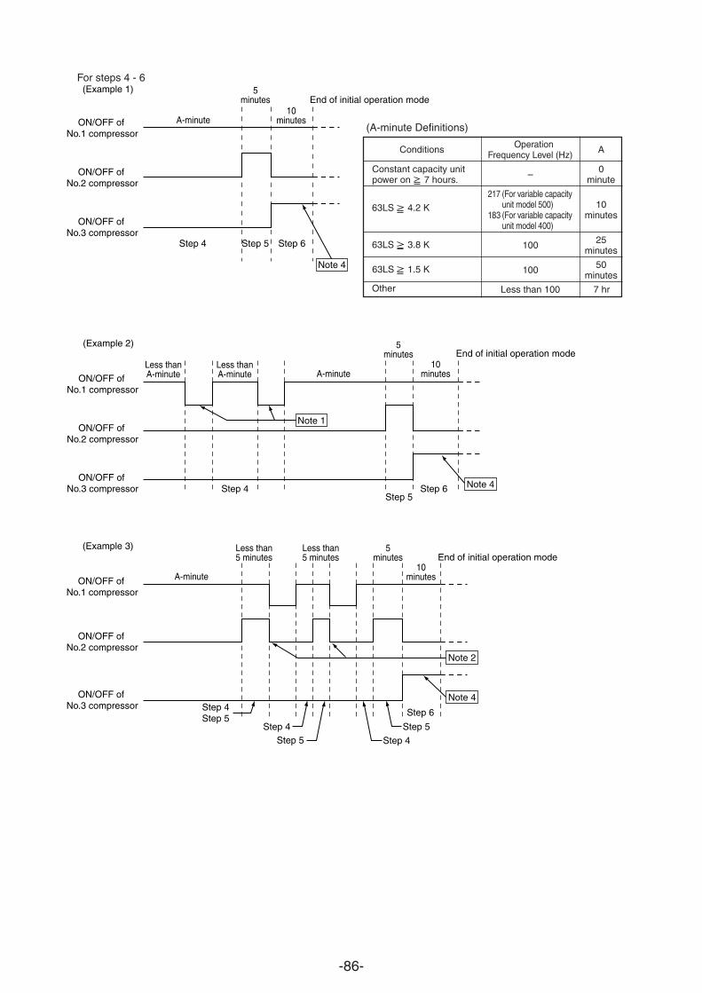
-86-
For steps 4 - 6
OperationFrequency Level (Hz)
–
217 (For variable capacityunit model 500)
183 (For variable capacityunit model 400)
100
100
Less than 100
Conditions
Constant capacity unitpower on 7 hours.
63LS 4.2 K
63LS 3.8 K
63LS 1.5 K
Other
(A-minute Definitions)
A
0minute
10minutes
25minutes
50minutes
7 hr
(Example 1)
A-minute
Step 4 Step 5 Step 6
10minutes
5minutes
ON/OFF of No.1 compressor
ON/OFF of No.2 compressor
ON/OFF of No.3 compressor
End of initial operation mode
Note 4
(Example 2)
A-minuteLess thanA-minute
Less thanA-minute
Step 4 Step 6Step 5
10minutes
5minutes
ON/OFF of No.1 compressor
ON/OFF of No.2 compressor
ON/OFF of No.3 compressor
End of initial operation mode
Note 1
Note 4
(Example 3)
A-minute
Less than5 minutes
Less than5 minutes
Step 6
Step 5
Step 4Step 5Step 4
Step 4Step 5
10minutes
5minutes
ON/OFF of No.1 compressor
ON/OFF of No.2 compressor
ON/OFF of No.3 compressor
End of initial operation mode
Note 2
Note 4
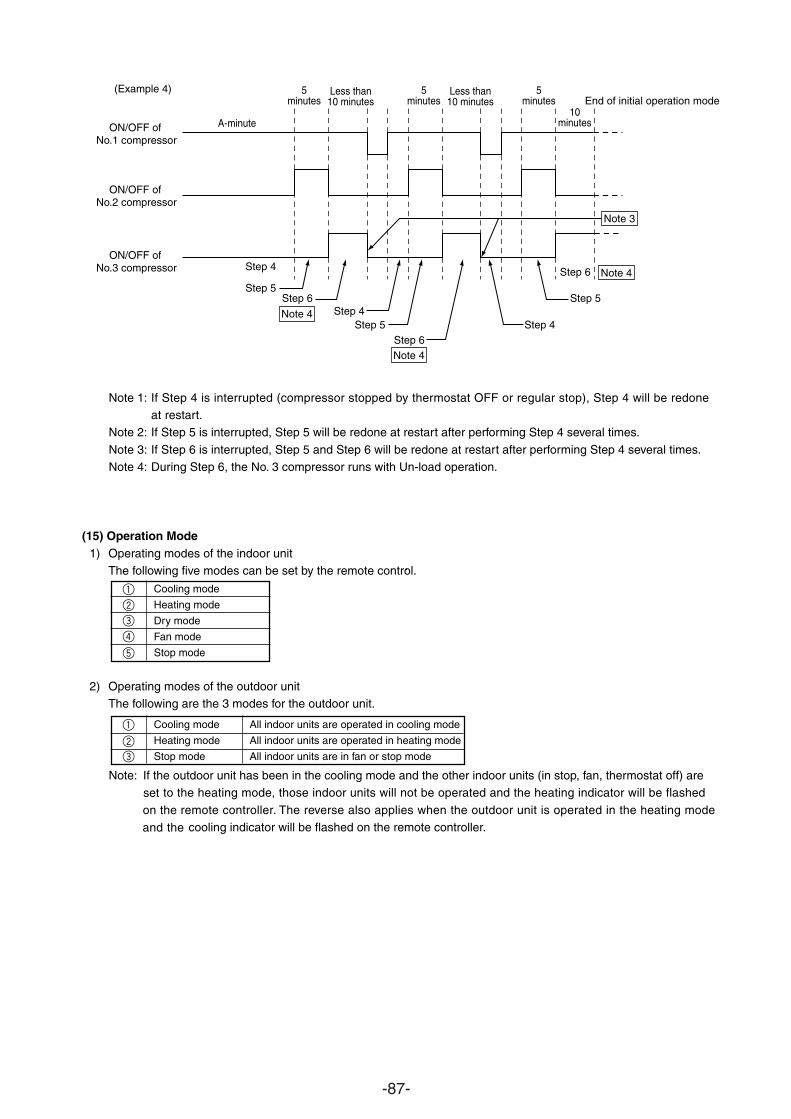
-87-
Note 1: If Step 4 is interrupted (compressor stopped by thermostat OFF or regular stop), Step 4 will be redone t.at restar
Note 2: If Step 5 is interrupted, Step 5 will be redone at restart after performing Step 4 several times.
Note 3: If Step 6 is interrupted, Step 5 and Step 6 will be redone at restart after performing Step 4 several times.Note 4: During Step 6, the No. 3 compressor runs with Un-load operation.
(15) Operation Mode1) Operating modes of the indoor unit
The following five modes can be set by the remote control.
Cooling mode
Heating mode
Dry mode
Fan mode
Stop mode
2) Operating modes of the outdoor unitThe following are the 3 modes for the outdoor unit.
Cooling mode All indoor units are operated in cooling mode
Heating mode All indoor units are operated in heating mode
Stop mode All indoor units are in fan or stop mode
Note: If the outdoor unit has been in the cooling mode and the other indoor units (in stop, fan, thermostat off) are to the heating mode, those indoor units will not be operated and the heating indicator will be flashed set
remote controller. The reverse also applies when the outdoor unit is operated in the heating mode cooling indicator will be flashed on the remote controller.and the
.
(Example 4)
A-minute
Less than10 minutes
Step 5Step 6 Step 5
Step 6
Step 4Step 5 Step 4
Step 6
10minutes
5minutes
Less than10 minutes
5minutes
5minutes
ON/OFF of No.1 compressor
ON/OFF of No.2 compressor
ON/OFF of No.3 compressor
End of initial operation mode
Note 3
Step 4
Note 4
Note 4
Note 4
on the
1
1
2
2
3
3
4
5
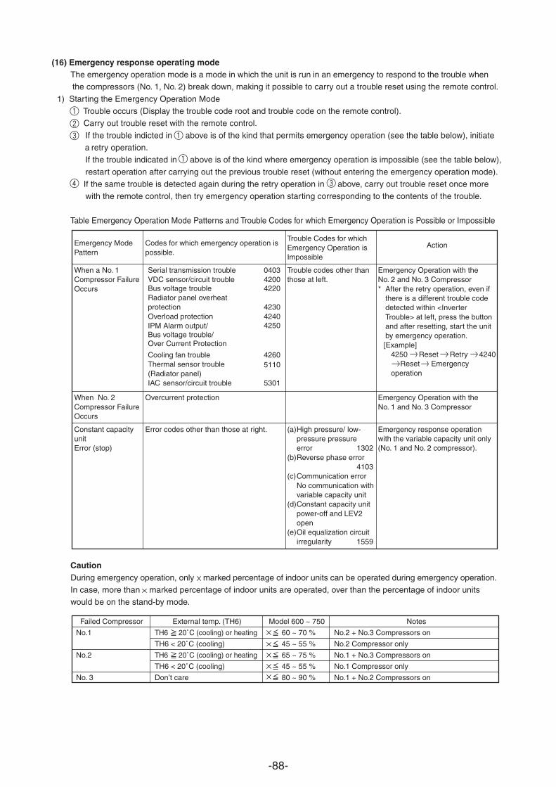
-88-
(16) Emergency response operating modeThe emergency operation mode is a mode in which the unit is run in an emergency to respond to the trouble when
compressors (No. 1, No. 2) break down, making it possible to carry out a trouble reset using the remote control.the
1) Starting the Emergency Operation Mode Trouble occurs (Display the trouble code root and trouble code on the remote control). Carry out trouble reset with the remote control.
If the trouble indicted in above is of the kind that permits emergency operation (see the table below), initiateretry operation. a
If the trouble indicated in above is of the kind where emergency operation is impossible (see the table below),
restart operation after carrying out the previous trouble reset (without entering the emergency operation mode). If the same trouble is detected again during the retry operation in above, carry out trouble reset once more
with the remote control, then try emergency operation starting corresponding to the contents of the trouble.
Table Emergency Operation Mode Patterns and Trouble Codes for which Emergency Operation is Possible or Impossible
Codes for which emergency operation ispossible.
Overcurrent protection
Error codes other than those at right.
Emergency ModePattern
When a No. 1Compressor FailureOccurs
When No. 2Compressor FailureOccurs
Constant capacityunitError (stop)
Trouble Codes for whichEmergency Operation isImpossible
Trouble codes other thanthose at left.
(a)High pressure/ low-pressure pressureerror 1302
(b)Reverse phase error4103
(c)Communication errorNo communication withvariable capacity unit
(d)Constant capacity unitpower-off and LEV2open
(e)Oil equalization circuitirregularity 1559
Action
Emergency Operation with theNo. 2 and No. 3 Compressor * After the retry operation, even if
there is a different trouble codedetected within <InverterTrouble> at left, press the buttonand after resetting, start the unitby emergency operation.[Example]
4250 Reset Retry 4240Reset Emergency
operation
Emergency Operation with theNo. 1 and No. 3 Compressor
Emergency response operationwith the variable capacity unit only(No. 1 and No. 2 compressor).
Failed Compressor External temp. (TH6) Model 600 ~ 750 Notes
No.1 TH6 20˚C (cooling) or heating 60 ~ 70 % No.2 + No.3 Compressors on
TH6 < 20˚C (cooling) 45 ~ 55 % No.2 Compressor only
No.2 TH6 20˚C (cooling) or heating 65 ~ 75 % No.1 + No.3 Compressors on
TH6 < 20˚C (cooling) 45 ~ 55 % No.1 Compressor only
No. 3 Don’t care 80 ~ 90 % No.1 + No.2 Compressors on
CautionDuring emergency operation, only marked percentage of indoor units can be operated during emergency operation.In case, more than marked percentage of indoor units are operated, over than the percentage of indoor unitswould be on the stand-by mode.
1
1
1
3
2
3
4
Serial transmission trouble 0403VDC sensor/circuit trouble 4200Bus voltage trouble 4220Radiator panel overheatprotection 4230Overload protection 4240
4250IPM Alarm output/Bus voltage trouble/Over Current Protection
Cooling fan trouble 4260Thermal sensor trouble(Radiator panel)
5110
IAC sensor/circuit trouble 5301
-89-
2) Terminating Emergency Response Operation Mode(Termination Conditions)When one of the following conditions is met, emergency operation mode is terminated.
Cumulative compressor operation time in the cooling mode exceeds 4 hours.Cumulative compressor operation time in the heating mode exceeds 2 hours.Emergency operation mode trouble detected.
(Control During and After Termination)
• During and after termination, the compressor will be stopped and a repeat error code will be flashed on the
remote controller.• If there is a repeat trouble reset during termination, retry operations will start by repeating steps to in 1).
1
2
3
1 4
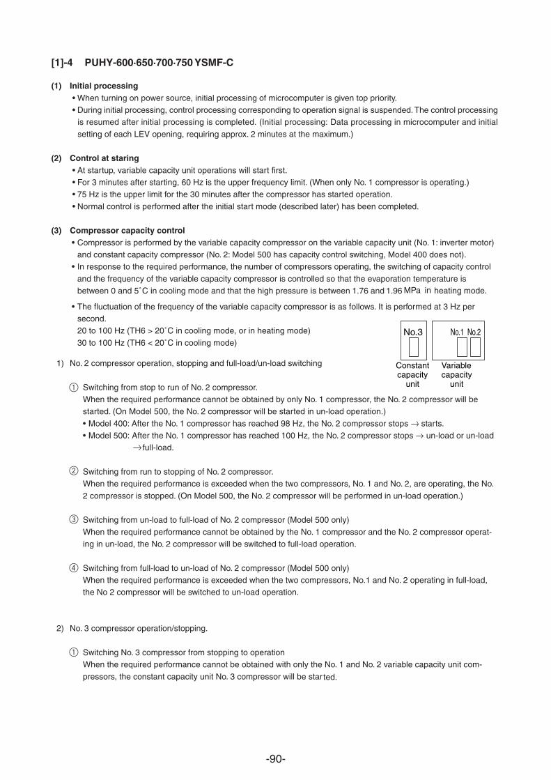
-90-
[1]-4 PUHY-600·650·700·750 YSMF-C
(1) Initial processing• When turning on power source, initial processing of microcomputer is given top priority.• During initial processing, control processing corresponding to operation signal is suspended. The control processing
is resumed after initial processing is completed. (Initial processing: Data processing in microcomputer and initial
setting of each LEV opening, requiring approx. 2 minutes at the maximum.)
(2) Control at staring• At startup, variable capacity unit operations will start first.• For 3 minutes after starting, 60 Hz is the upper frequency limit. (When only No. 1 compressor is operating.)• 75 Hz is the upper limit for the 30 minutes after the compressor has started operation.
• Normal control is performed after the initial start mode (described later) has been completed.
(3) Compressor capacity control• Compressor is performed by the variable capacity compressor on the variable capacity unit (No. 1: inverter motor)
and constant capacity compressor (No. 2: Model 500 has capacity control switching, Model 400 does not).• In response to the required performance, the number of compressors operating, the switching of capacity control
and the frequency of the variable capacity compressor is controlled so that the evaporation temperature isbetween 0 and 5˚C in cooling mode and that the high pressure is between 1.76 and 1.96 MPa in
• The fluctuation of the frequency of the variable capacity compressor is as follows. It is performed at 3 Hz persecond.20 to 100 Hz (TH6 > 20˚C in cooling mode, or in heating mode)
30 to 100 Hz (TH6 < 20˚C in cooling mode)
1) No. 2 compressor operation, stopping and full-load/un-load switching
Switching from stop to run of No. 2 compressor.When the required performance cannot be obtained by only No. 1 compressor, the No. 2 compressor will bestarted. (On Model 500, the No. 2 compressor will be started in un-load operation.)
• Model 400: After the No. 1 compressor has reached 98 Hz, the No. 2 compressor stops starts.• Model 500: After the No. 1 compressor has reached 100 Hz, the No. 2 compressor stops un-load or un-load
full-load.
Switching from run to stopping of No. 2 compressor.When the required performance is exceeded when the two compressors, No. 1 and No. 2, are operating, the No.
2 compressor is stopped. (On Model 500, the No. 2 compressor will be performed in un-load operation.)
Switching from un-load to full-load of No. 2 compressor (Model 500 only)
When the required performance cannot be obtained by the No. 1 compressor and the No. 2 compressor operat-ing in un-load, the No. 2 compressor will be switched to full-load operation.
Switching from full-load to un-load of No. 2 compressor (Model 500 only)When the required performance is exceeded when the two compressors, No.1 and No. 2 operating in full-load,the No 2 compressor will be switched to un-load operation.
2) No. 3 compressor operation/stopping.
Switching No. 3 compressor from stopping to operationWhen the required performance cannot be obtained with only the No. 1 and No. 2 variable capacity unit com-
pressors, the constant capacity unit No. 3 compressor will be star ted.
No.3 No.1 No.2
Constantcapacity
unit
Variablecapacity
unit1
2
3
4
1
heating mode.
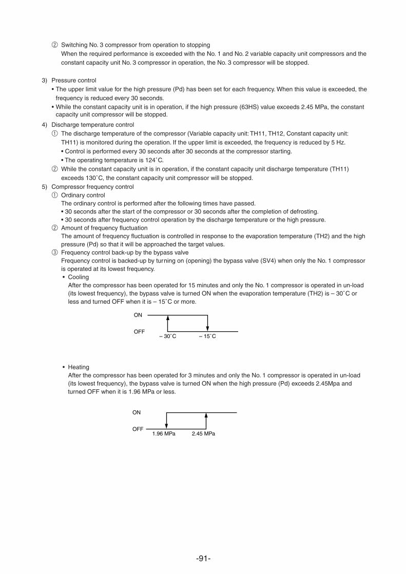
-91-
2 Switching No. 3 compressor from operation to stoppingWhen the required performance is exceeded with the No. 1 and No. 2 variable capacity unit compressors and theconstant capacity unit No. 3 compressor in operation, the No. 3 compressor will be stopped.
3) Pressure control• The upper limit value for the high pressure (Pd) has been set for each frequency. When this value is exceeded, the
frequency is reduced every 30 seconds.•
4) Discharge temperature control1 The discharge temperature of the compressor (Variable capacity unit: TH11, TH12, Constant capacity unit:
TH11) is monitored during the operation. If the upper limit is exceeded, the frequency is reduced by 5 Hz.
• Control is performed every 30 seconds after 30 seconds at the compressor starting.• The operating temperature is 124˚C.
2 While the constant capacity unit is in operation, if the constant capacity unit discharge temperature (TH11)
exceeds 130˚C, the constant capacity unit compressor will be stopped.5) Compressor frequency control
1 Ordinary controlThe ordinary control is performed after the following times have passed.• 30 seconds after the start of the compressor or 30 seconds after the completion of defrosting.• 30 seconds after frequency control operation by the discharge temperature or the high pressure.
2 Amount of frequency fluctuationThe amount of frequency fluctuation is controlled in response to the evaporation temperature (TH2) and the highpressure (Pd) so that it will be approached the target values.
3 Frequency control back-up by the bypass valveFrequency control is backed-up by turning on (opening) the bypass valve (SV4) when only the No. 1 compressor is operated at its lowest frequency.• Cooling
After the compressor has been operated for 15 minutes and only the No. 1 compressor is operated in un-load(its lowest frequency), the bypass valve is turned ON when the evaporation temperature (TH2) is – 30˚C orless and turned OFF when it is – 15˚C or more.
• HeatingAfter the compressor has been operated for 3 minutes and only the No. 1 compressor is operated in un-load(its lowest frequency), the bypass valve is turned ON when the high pressure (Pd) exceeds 2.45Mpa and
ON
OFF
– 30˚C
ON
OFF– 15˚C
1.96 MPa 2.45 MPa
While the constant capacity unit is in operation, if the high pressure (63HS) value exceeds 2.45 MPa, the constant capacity unit compressor will be stopped.
turned OFF when it is 1.96 MPa or less.
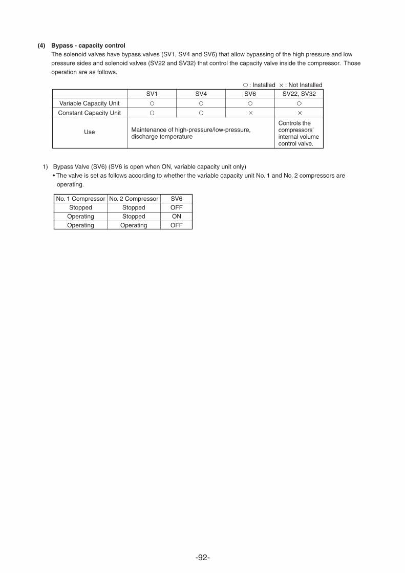
-92-
(4) Bypass - capacity controlThe solenoid valves have bypass valves (SV1, SV4 and SV6) that allow bypassing of the high pressure and lowpressure sides and solenoid valves (SV22 and SV32) that control the capacity valve inside the compressor. Those
operation are as follows.
: Installed : Not InstalledSV1 SV4 SV6 SV22, SV32
Variable Capacity Unit
Constant Capacity Unit
Use
1) Bypass Valve (SV6) (SV6 is open when ON, variable capacity unit only)• The valve is set as follows according to whether the variable capacity unit No. 1 and No. 2 compressors are
operating.
No. 1 Compressor No. 2 Compressor SV6Stopped Stopped OFF
Operating Stopped ON
Operating Operating OFF
Maintenance of high-pressure/low-pressure,discharge temperature
Controls thecompressors’internal volumecontrol valve.
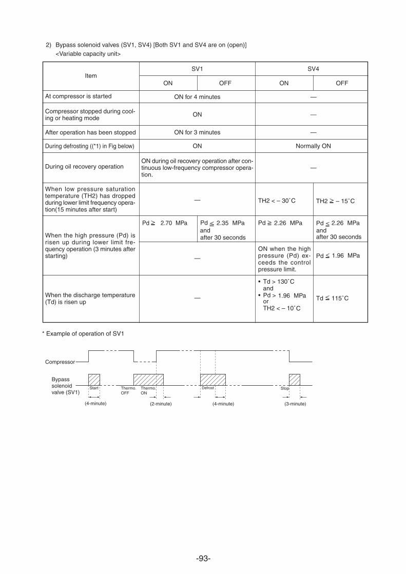
-93-
Item
At compressor is started
Compressor stopped during cool-ing or heating mode
After operation has been stopped
During defrosting ((*1) in Fig below)
During oil recovery operation
When low pressure saturationtemperature (TH2) has droppedduring lower limit frequency opera-tion(15 minutes after start)
When the high pressure (Pd) isrisen up during lower limit fre-quency operation (3 minutes afterstarting)
When the discharge temperature(Td) is risen up
TH2 – 15˚C
Pd 2.26 MPa andafter 30 seconds
Pd 1.96 MPa
Td 115˚C
* Example of operation of SV1
Compressor
Bypasssolenoidvalve (SV1)
(4-minute) (2-minute) (4-minute) (3-minute)
Start Thermo.OFF
Thermo.ON
Defrost Stop
2) Bypass solenoid valves (SV1, SV4) [Both SV1 and SV4 are on (open)]<Variable capacity unit>
SV1
ON OFF
ON for 4 minutes
ON
ON for 3 minutes
ON
ON during oil recovery operation after con-tinuous low-frequency compressor opera-tion.
—
—
—
TH2 < – 30˚C
Pd 2.26 MPa
ON when the highpressure (Pd) ex-ceeds the controlpressure limit.
• Td > 130˚Cand
• Pd > 1.96 MPaorTH2 < – 10˚C
SV4
ON OFF
—
—
—
Normally ON
—
Pd 2.70 MPa Pd 2.35 MPa andafter 30 seconds
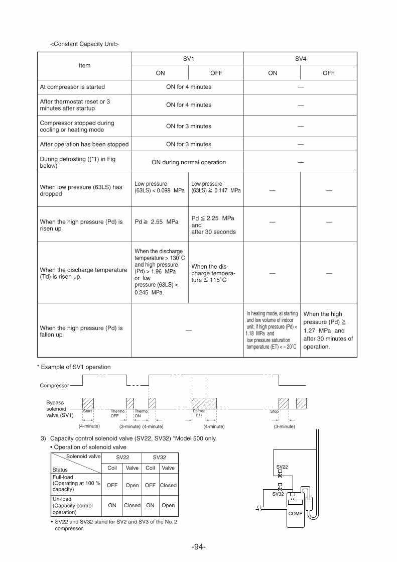
-94-
Item
At compressor is started
After thermostat reset or 3minutes after startup
Compressor stopped duringcooling or heating mode
After operation has been stopped
During defrosting ((*1) in Figbelow)
When low pressure (63LS) hasdropped
When the high pressure (Pd) isrisen up
When the discharge temperature(Td) is risen up.
When the high pressure (Pd) isfallen up.
* Example of SV1 operation
Compressor
Bypasssolenoidvalve (SV1)
(4-minute) (3-minute) (4-minute) (3-minute)
Start Thermo.OFF
Thermo.ON
Defrost(*1)
Stop
<Constant Capacity Unit>
SV1
ON for 4 minutes
ON for 4 minutes
ON for 3 minutes
ON for 3 minutes
ON during normal operation
—
SV4
—
—
—
—
—
3) Capacity control solenoid valve (SV22, SV32) *Model 500 only.
• Operation of solenoid valve
• SV22 and SV32 stand for SV2 and SV3 of the No. 2compressor.
Solenoid valve
SV22
SV32
COMP
SV22 SV32
Coil Valve Coil Valve
OFF Open OFF Closed
ON Closed ON Open
StatusFull-load(Operating at 100 %capacity)
Un-load(Capacity controloperation)
ON OFF
Low pressure(63LS) < 0.098 MPa
Pd 2.55 MPa
When the dischargetemperature > 130˚Cand high pressure(Pd) > 1.96 MPa or lowpressure (63LS) <0.245 MPa.
Low pressure(63LS) 0.147 MPa
Pd 2.25 MPa andafter 30 seconds
When the dis-charge tempera-ture 115˚C
—
—
—
In heating mode, at startingand low volume of indoorunit, if high pressure (Pd) <1.18 MPa andlow pressure saturationtemperature (ET) < – 20˚C
—
—
—
When the highpressure (Pd)
1.27 MPa andafter 30 minutes ofoperation.
(4-minute)
ON OFF
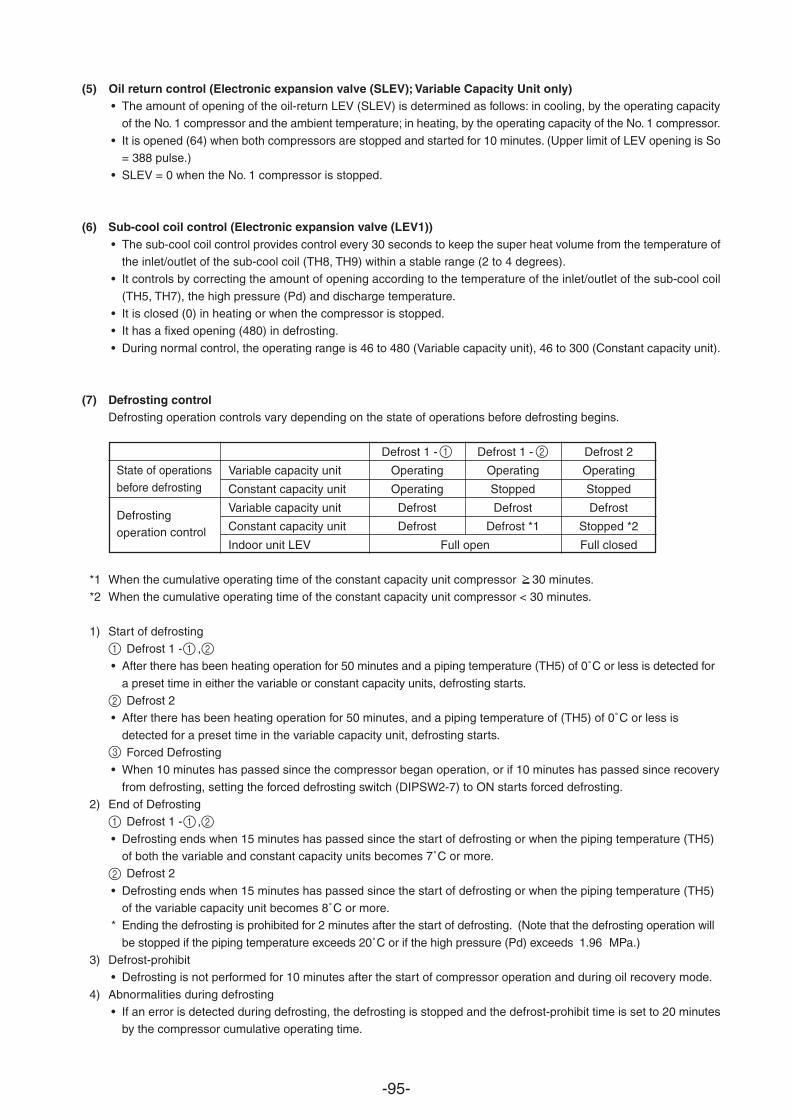
-95-
(5) Oil return control (Electronic expansion valve (SLEV); Variable Capacity Unit only)• The amount of opening of the oil-return LEV (SLEV) is determined as follows: in cooling, by the operating capacity
of the No. 1 compressor and the ambient temperature; in heating, by the operating capacity of the No. 1 compressor.
• It is opened (64) when both compressors are stopped and started for 10 minutes. (Upper limit of LEV opening is So= 388 pulse.)
• SLEV = 0 when the No. 1 compressor is stopped.
(6) Sub-cool coil control (Electronic expansion valve (LEV1))• The sub-cool coil control provides control every 30 seconds to keep the super heat volume from the temperature of
the inlet/outlet of the sub-cool coil (TH8, TH9) within a stable range (2 to 4 degrees).• It controls by correcting the amount of opening according to the temperature of the inlet/outlet of the sub-cool coil
(TH5, TH7), the high pressure (Pd) and discharge temperature.• It is closed (0) in heating or when the compressor is stopped.• It has a fixed opening (480) in defrosting.
• During normal control, the operating range is 46 to 480 (Variable capacity unit), 46 to 300 (Constant capacity unit).
(7) Defrosting controlDefrosting operation controls vary depending on the state of operations before defrosting begins.
Defrost 1 - Defrost 1 - Defrost 2
Variable capacity unit Operating Operating Operating
Constant capacity unit Operating Stopped Stopped
Variable capacity unit Defrost Defrost Defrost
Constant capacity unit Defrost Defrost *1 Stopped *2
Indoor unit LEV Full open Full closed
*1 When the cumulative operating time of the constant capacity unit compressor 30 minutes.*2 When the cumulative operating time of the constant capacity unit compressor < 30 minutes.
1) Start of defrosting Defrost 1 - ,
• After there has been heating operation for 50 minutes and a piping temperature (TH5) of 0˚C or less is detected for
a preset time in either the variable or constant capacity units, defrosting starts. Defrost 2
• After there has been heating operation for 50 minutes, and a piping temperature of (TH5) of 0˚C or less is
detected for a preset time in the variable capacity unit, defrosting starts. Forced Defrosting
• When 10 minutes has passed since the compressor began operation, or if 10 minutes has passed since recovery
from defrosting, setting the forced defrosting switch (DIPSW2-7) to ON starts forced defrosting.2) End of Defrosting
Defrost 1 - ,
• Defrosting ends when 15 minutes has passed since the start of defrosting or when the piping temperature (TH5)of both the variable and constant capacity units becomes 7˚C or more. Defrost 2
• Defrosting ends when 15 minutes has passed since the start of defrosting or when the piping temperature (TH5)of the variable capacity unit becomes 8˚C or more.
* Ending the defrosting is prohibited for 2 minutes after the start of defrosting. (Note that the defrosting operation will
be stopped if the piping temperature exceeds 20˚C or if the high pressure (Pd) exceeds 1.96 MPa.)3) Defrost-prohibit
• Defrosting is not performed for 10 minutes after the start of compressor operation and during oil recovery mode.
4) Abnormalities during defrosting• If an error is detected during defrosting, the defrosting is stopped and the defrost-prohibit time is set to 20 minutes
by the compressor cumulative operating time.
State of operationsbefore defrosting
Defrostingoperation control
1 2
1 1 2
2
3
1 1 2
2
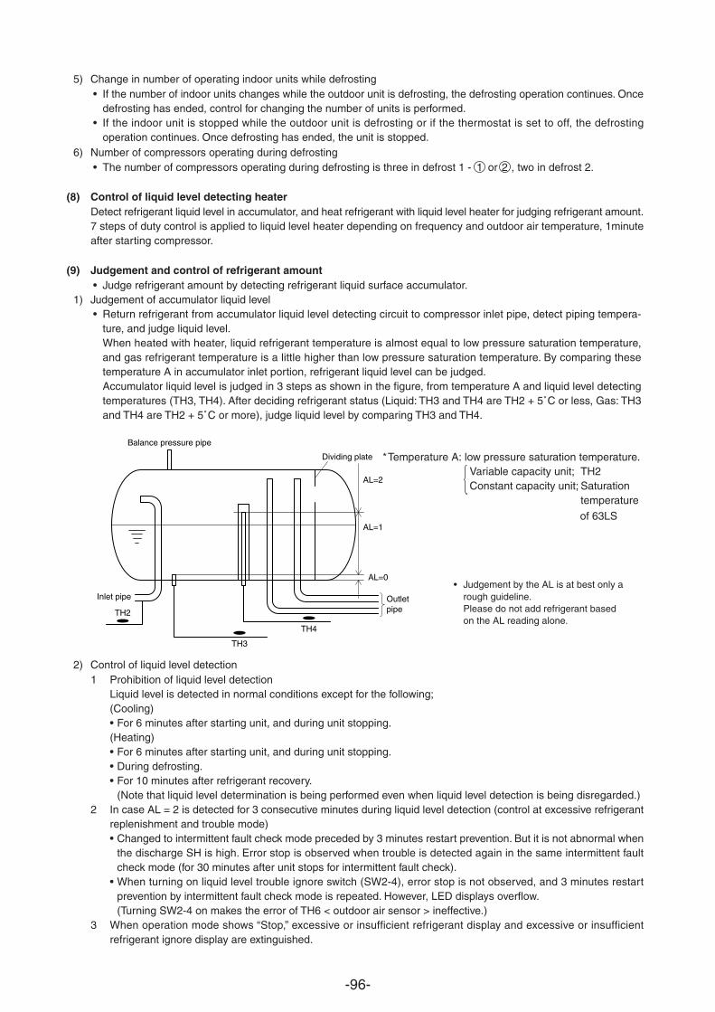
-96-
5) Change in number of operating indoor units while defrosting• If the number of indoor units changes while the outdoor unit is defrosting, the defrosting operation continues. Once
defrosting has ended, control for changing the number of units is performed.• If the indoor unit is stopped while the outdoor unit is defrosting or if the thermostat is set to off, the defrosting
operation continues. Once defrosting has ended, the unit is stopped.6) Number of compressors operating during defrosting
• The number of compressors operating during defrosting is three in defrost 1 - 1 or 2 , two in defrost 2.
(8) Control of liquid level detecting heaterDetect refrigerant liquid level in accumulator, and heat refrigerant with liquid level heater for judging refrigerant amount.7 steps of duty control is applied to liquid level heater depending on frequency and outdoor air temperature, 1minuteafter starting compressor.
(9) Judgement and control of refrigerant amount• Judge refrigerant amount by detecting refrigerant liquid surface accumulator.
1) Judgement of accumulator liquid level• Return refrigerant from accumulator liquid level detecting circuit to compressor inlet pipe, detect piping tempera-
ture, and judge liquid level.When heated with heater, liquid refrigerant temperature is almost equal to low pressure saturation temperature,and gas refrigerant temperature is a little higher than low pressure saturation temperature. By comparing thesetemperature A in accumulator inlet portion, refrigerant liquid level can be judged.Accumulator liquid level is judged in 3 steps as shown in the figure, from temperature A and liquid level detectingtemperatures (TH3, TH4). After deciding refrigerant status (Liquid: TH3 and TH4 are TH2 + 5˚C or less, Gas: TH3and TH4 are TH2 + 5˚C or more), judge liquid level by comparing TH3 and TH4.
2) Control of liquid level detection1 Prohibition of liquid level detection
Liquid level is detected in normal conditions except for the following;(Cooling)• For 6 minutes after starting unit, and during unit stopping.(Heating)• For 6 minutes after starting unit, and during unit stopping.• During defrosting.• For 10 minutes after refrigerant recovery.
(Note that liquid level determination is being performed even when liquid level detection is being disregarded.)2 In case AL = 2 is detected for 3 consecutive minutes during liquid level detection (control at excessive refrigerant
replenishment and trouble mode)• Changed to intermittent fault check mode preceded by 3 minutes restart prevention. But it is not abnormal when
the discharge SH is high. Error stop is observed when trouble is detected again in the same intermittent faultcheck mode (for 30 minutes after unit stops for intermittent fault check).
• When turning on liquid level trouble ignore switch (SW2-4), error stop is not observed, and 3 minutes restartprevention by intermittent fault check mode is repeated. However, LED displays overflow.(Turning SW2-4 on makes the error of TH6 < outdoor air sensor > ineffective.)
3 When operation mode shows “Stop,” excessive or insufficient refrigerant display and excessive or insufficientrefrigerant ignore display are extinguished.
TH3
TH4
Balance pressure pipe
TH2
AL=0
AL=1
AL=2
Dividing plate
Outletpipe
Inlet pipe• Judgement by the AL is at best only a
rough guideline.Please do not add refrigerant basedon the AL reading alone.
*Temperature A: low pressure saturation temperature.Variable capacity unit; TH2Constant capacity unit; Saturation
temperature
of 63LS
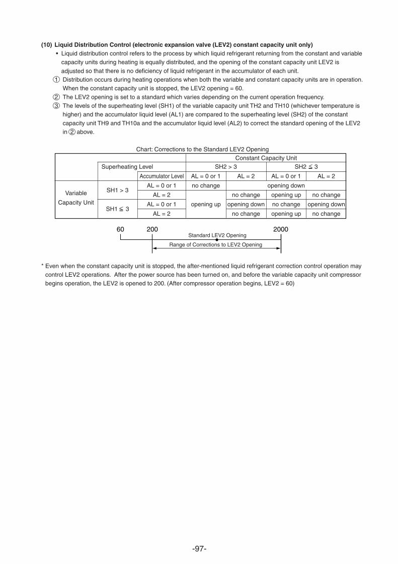
-97-
(10) Liquid Distribution Control (electronic expansion valve (LEV2) constant capacity unit only)• Liquid distribution control refers to the process by which liquid refrigerant returning from the constant and variable
capacity units during heating is equally distributed, and the opening of the constant capacity unit LEV2 is
so that there is no deficiency of liquid refrigerant in the accumulator of each unit.adjusted1 Distribution occurs during heating operations when both the variable and constant capacity units are in operation.
When the constant capacity unit is stopped, the LEV2 opening = 60.
2 The LEV2 opening is set to a standard which varies depending on the current operation frequency.3 The levels of the superheating level (SH1) of the variable capacity unit TH2 and TH10 (whichever temperature is
higher) and the accumulator liquid level (AL1) are compared to the superheating level (SH2) of the constant
capacity unit TH9 and TH10a and the accumulator liquid level (AL2) to correct the standard opening of the LEV2in 2 above.
Chart: Corrections to the Standard LEV2 OpeningConstant Capacity Unit
Superheating Level SH2 > 3 SH2 3
Accumulator Level AL = 0 or 1 AL = 2 AL = 0 or 1 AL = 2
Variable SH1 > 3AL = 0 or 1 no change opening down
Capacity UnitAL = 2 no change opening up no change
SH1 3AL = 0 or 1 opening up opening down no change opening down
AL = 2 no change opening up no change
* Even when the constant capacity unit is stopped, the after-mentioned liquid refrigerant correction control operation maycontrol LEV2 operations. After the power source has been turned on, and before the variable capacity unit compressorbegins operation, the LEV2 is opened to 200. (After compressor operation begins, LEV2 = 60)
60 200 2000Standard LEV2 Opening
Range of Corrections to LEV2 Opening

-98-
(11) Liquid Refrigerant Correction ControlThe liquid refrigerant correction control adjusts the liquid refrigerant amounts between both accumulators in theunlikely event that the liquid refrigerant amount in both the constant and variable capacity unit accumulators should
be insufficient, or if and excessive amount of liquid refrigerant is returned from either accumulator.During this operation, Service LED No. 4 on the variable capacity unit will light up.
Direction of Accumula-tor Liquid Transfer
Variable Capacity UnitConstant Capacity Unit
Indoor Unit
Variable Capacity Unit
Constant Capacity Unit
Variable Capacity Unit
Constant Capacity Unit
Variable Capacity Unit
Constant Capacity Unit
Variable Capacity Unit
Constant Capacity Unit
Constant Capacity Unit
Variable Capacity Unit
Constant Capacity Unit
Variable Capacity Unit
Start Conditions
• In heating mode• Run and stop indoor unitsare mixed.
• Pd 13k (1.27 MPa), orduring an accumulatoroverflow preliminary error.
• Td < 110˚C
• In heating mode• While the constant capacityunit is stopped.
• During an accumulatoroverflow preliminary errorin the variable capacity unit(AL1 = 2)
• TdSH < 40 deg *1
• In heating mode• During constant capacityunit operation
• When AL1 = 2 is detected inthe variable capacity unit.
• TdSH < 40 deg *1
• In cooling mode• While the constant capacityunit is stopped.
• During an accumulatoroverflow preliminary errorin the variable capacity unit(AL1 = 2)
• Constant capacity unitAL2 = 0 or 1
• Variable capacity unitTH6 < 25˚C
• In heating mode• Constant capacity unitswitches from operation tostopping.
• Constant capacity unit AL2 = 0
• In heating mode• During an accumulatoroverflow error delay in theconstant capacity unit(AL2 = 2)
• Variable capacity unitAL1 = 0 or 1
• During cooling or heating• During an accumulatoroverflow preliminary errorin the constant capacityunit (AL2 = 2)
• Variable capacity unitAL1 = 0 or 1
Actuator Action
Com-pressor
–
OFF
OFF
OFF
OFF
–
OFF
Constant Capacity Unit Variablecapacity
unit
–
–
–
Opera-tionfre-quencylevelup
–
Opera-tionfre-quencyleveldown
21S4a,bON
IndoorUnit
Opera-tion:nor-malcontrol
Stop:LEV = 60
–
–
AllindoorunitLEV = 60
–
–
AllindoorunitLEV = 60
StoppingConditions
While allindoor unitsare operat-ingTd 115˚C
• AL1 = 0 or 1• Continuingfor 20minutes
• AL1 = 0 or 1• AL2 = 2• Continuingfor 10minutes
• AL1 = 0 or 1• Continuingfor 15minutes
• AL1 = 0 or 1• Continuingfor 3 ~ 6minutes
• AL2 = 0 or 1• AL1 = 2• Continuingfor 10minutes
• AL1 = 2• Continuingfor 4minutes
LED MonitorNo.4
• Verifysurplusrefrigerant
• LD1 lightsup
Liquidrefrigerantcontrol 2LD3 lightsup
Liquidrefrigerantcontrol 4LD5 lightsup
Liquidrefrigerantcontrol 6LD7 lightsup
Liquidrefrigerantcontrol 7LD8 lightsup
Liquidrefrigerantcontrol 3LD4 lightsup
Liquidrefrigerantcontrol 5LD6 lightsup
LEV2
–
2000
2000
2000
2000
–
2000
SV5b
–
ON(open)
ON(open)
ON(open)
ON(open)
–
ON(open)
Other
–
–
–
FanON
–
–
LEV1 =480SV4 ON21S4OFF
* 1 TdSH (Discharge temperature superheating) = Discharge temperature (TH11 or TH12) - Tc (High pressure saturationtemperature)
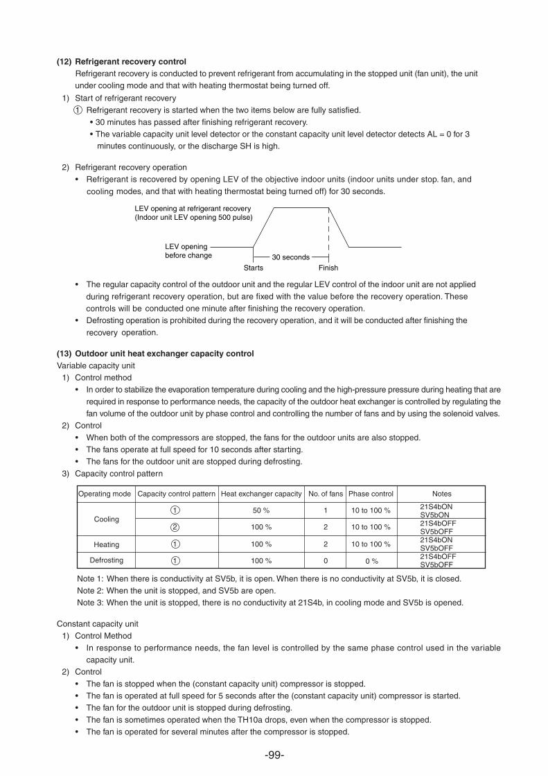
-99-
(12) Refrigerant recovery controlRefrigerant recovery is conducted to prevent refrigerant from accumulating in the stopped unit (fan unit), the unit
cooling mode and that with heating thermostat being turned off.under
1) Start of refrigerant recovery1 Refrigerant recovery is started when the two items below are fully satisfied.
• 30 minutes has passed after finishing refrigerant recovery.• The variable capacity unit level detector or the constant capacity unit level detector detects AL = 0 for 3
continuously, or the discharge SH is high.minutes
2) Refrigerant recovery operation• Refrigerant is recovered by opening LEV of the objective indoor units (indoor units under stop. fan, and
modes, and that with heating thermostat being turned off) for 30 seconds.cooling
• The regular capacity control of the outdoor unit and the regular LEV control of the indoor unit are not applied
refrigerant recovery operation, but are fixed with the value before the recovery operation. These duringconducted one minute after finishing the recovery operation.controls will be
• Defrosting operation is prohibited during the recovery operation, and it will be conducted after finishing the
operation.recovery
(13) Outdoor unit heat exchanger capacity controlVariable capacity unit
1) Control method• In order to stabilize the evaporation temperature during cooling and the high-pressure pressure during heating that are
required in response to performance needs, the capacity of the outdoor heat exchanger is controlled by regulating thefan volume of the outdoor unit by phase control and controlling the number of fans and by using the solenoid valves.
2) Control
• When both of the compressors are stopped, the fans for the outdoor units are also stopped.• The fans operate at full speed for 10 seconds after starting.• The fans for the outdoor unit are stopped during defrosting.
3) Capacity control pattern
Note 1: When there is conductivity at SV5b, it is open. When there is no conductivity at SV5b, it is closed.Note 2: When the unit is stopped, and SV5b are open.Note 3: When the unit is stopped, there is no conductivity at 21S4b, in cooling mode and SV5b is opened.
Constant capacity unit1) Control Method
• In response to performance needs, the fan level is controlled by the same phase control used in the variablecapacity unit.
2) Control
• The fan is stopped when the (constant capacity unit) compressor is stopped.• The fan is operated at full speed for 5 seconds after the (constant capacity unit) compressor is started.• The fan for the outdoor unit is stopped during defrosting.
• The fan is sometimes operated when the TH10a drops, even when the compressor is stopped.• The fan is operated for several minutes after the compressor is stopped.
Operating mode Capacity control pattern Heat exchanger capacity No. of fans Phase control Notes
1 50 % 1 10 to 100 %
2 100 % 2 10 to 100 %
1 100 % 2 10 to 100 %
1 100 % 0 0 %
Starts
LEV openingbefore change
LEV opening at refrigerant recovery(Indoor unit LEV opening 500 pulse)
Finish30 seconds
Cooling
Heating
Defrosting
21S4bONSV5bON21S4bOFFSV5bOFF21S4bONSV5bOFF21S4bOFFSV5bOFF
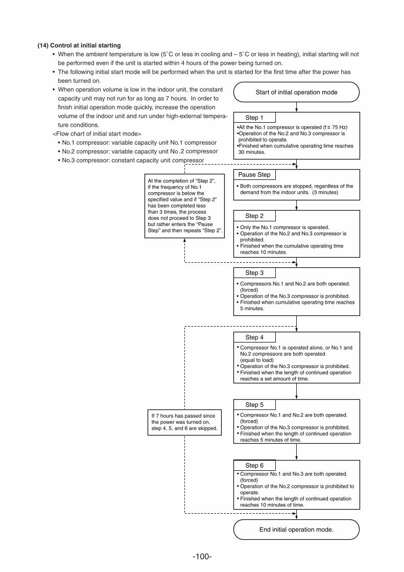
-100-
(14) Control at initial starting• When the ambient temperature is low (5˚C or less in cooling and – 5˚C or less in heating), initial starting will not
be performed even if the unit is started within 4 hours of the power being turned on.
• The following initial start mode will be performed when the unit is started for the first time after the power hasbeen turned on.
• When operation volume is low in the indoor unit, the constant
capacity unit may not run for as long as 7 hours. In order tofinish initial operation mode quickly, increase the operationvolume of the indoor unit and run under high-external tempera-
ture conditions.<Flow chart of initial start mode>
• No.1 compressor: variable capacity unit No.1 compressor
• No.2 compressor: variable capacity unit No .2 compressor
• No.3 compressor: constant capacity unit compressor
Start of initial operation mode
End initial operation mode.
Step 1
•All the No.1 compressor is operated (f 75 Hz)•Operation of the No.2 and No.3 compressor is prohibited to operate.•Finished when cumulative operating time reaches 30 minutes.
Pause Step
• Both compressors are stopped, regardless of thedemand from the indoor units. (3 minutes)
Step 2
••
•
Only the No.1 compressor is operated. Operation of the No.2 and No.3 compressor isprohibited.Finished when the cumulative operating timereaches 10 minutes.
Step 3
Step 4
Step 5
Step 6
•
••
Compressors No.1 and No.2 are both operated. (forced)Operation of the No.3 compressor is prohibited.Finished when cumulative operating time reaches 5 minutes.
Compressor No.1 is operated alone, or No.1 andNo.2 compressors are both operated.(equal to load)Operation of the No.3 compressor is prohibited.Finished when the length of continued operationreaches a set amount of time.
•
••
•
••
•
•
•
If 7 hours has passed sincethe power was turned on,step 4, 5, and 6 are skipped.
At the completion of “Step 2”,if the frequency of No.1compressor is below thespecified value and if “Step 2”has been completed lessthan 3 times, the processdoes not proceed to Step 3but rather enters the “PauseStep” and then repeats “Step 2”.
Compressor No.1 and No.2 are both operated.(forced)Operation of the No.3 compressor is prohibited.Finished when the length of continued operationreaches 5 minutes of time.
Compressor No.1 and No.3 are both operated.(forced)Operation of the No.2 compressor is prohibited tooperate.Finished when the length of continued operationreaches 10 minutes of time.
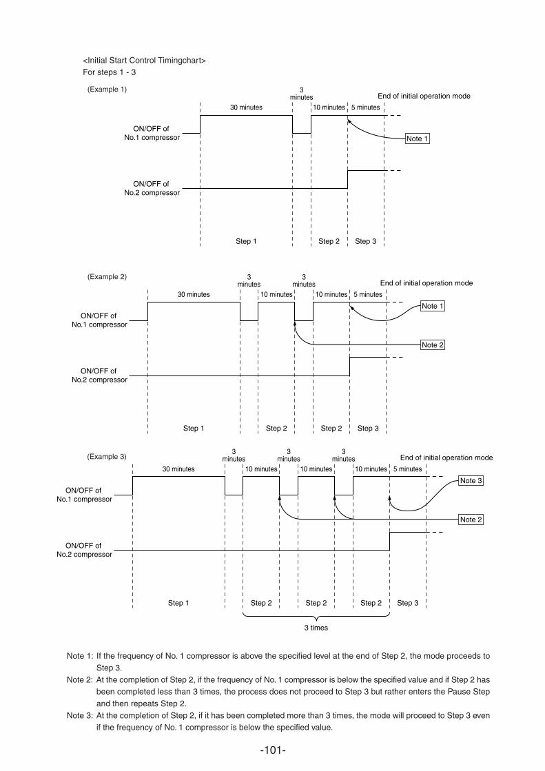
-101-
<Initial Start Control Timingchart>For steps 1 - 3
Note 1: If the frequency of No. 1 compressor is above the specified level at the end of Step 2, the mode proceeds to
Step 3.Note 2: At the completion of Step 2, if the frequency of No. 1 compressor is below the specified value and if Step 2 has
been completed less than 3 times, the process does not proceed to Step 3 but rather enters the Pause Step
and then repeats Step 2.Note 3: At the completion of Step 2, if it has been completed more than 3 times, the mode will proceed to Step 3 even
if the frequency of No. 1 compressor is below the specified value.
30 minutes
Step 1
3minutes
10 minutes
Step 2
5 minutes
Step 3
ON/OFF of No.1 compressor
ON/OFF of No.2 compressor
End of initial operation mode
Note 1
30 minutes
Step 1
3minutes
10 minutes
Step 2
3minutes
10 minutes
Step 2
5 minutes
Step 3
Note 1ON/OFF of
No.1 compressor
ON/OFF of No.2 compressor
Note 2
End of initial operation mode
30 minutes
Step 1
3minutes
10 minutes
Step 2
3minutes
10 minutes
Step 2
3 times
3minutes
10 minutes
Step 2
5 minutes
Step 3
Note 3ON/OFF of
No.1 compressor
ON/OFF of No.2 compressor
Note 2
End of initial operation mode
(Example 1)
(Example 2)
(Example 3)
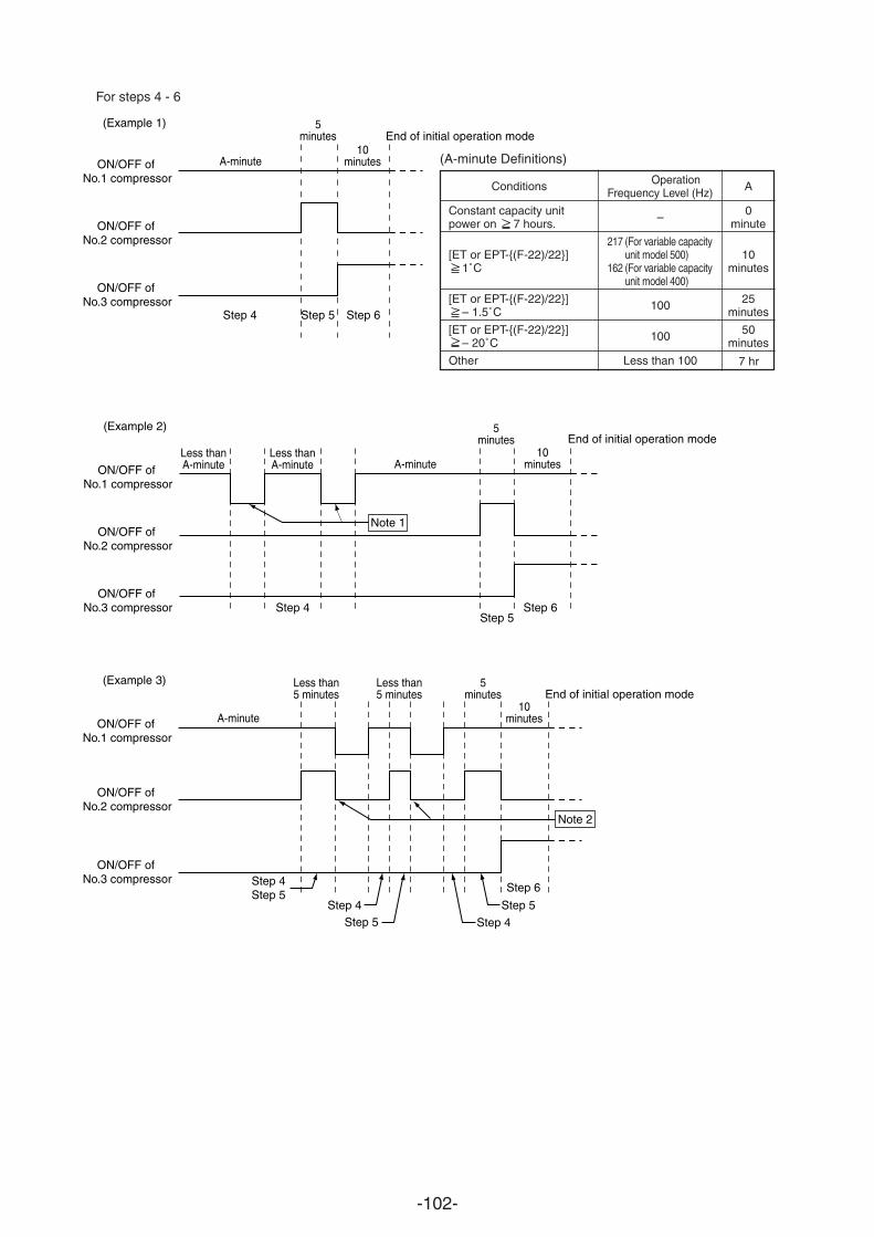
-102-
For steps 4 - 6
(Example 1)
A-minute
Step 4 Step 5 Step 6
10minutes
5minutes
ON/OFF of No.1 compressor
ON/OFF of No.2 compressor
ON/OFF of No.3 compressor
End of initial operation mode
OperationFrequency Level (Hz)
–
217 (For variable capacityunit model 500)
162 (For variable capacityunit model 400)
100
100
Less than 100
Conditions
Constant capacity unitpower on 7 hours.
[ET or EPT-(F-22)/22] 1˚C
[ET or EPT-(F-22)/22] – 1.5˚C
[ET or EPT-(F-22)/22] – 20˚C
Other
(A-minute Definitions)
A
0minute
10minutes
25minutes
50minutes
7 hr
(Example 2)
A-minuteLess thanA-minute
Less thanA-minute
Step 4 Step 6Step 5
10minutes
5minutes
ON/OFF of No.1 compressor
ON/OFF of No.2 compressor
ON/OFF of No.3 compressor
End of initial operation mode
Note 1
(Example 3)
A-minute
Less than5 minutes
Less than5 minutes
Step 6
Step 5
Step 4Step 5Step 4
Step 4Step 5
10minutes
5minutes
ON/OFF of No.1 compressor
ON/OFF of No.2 compressor
ON/OFF of No.3 compressor
End of initial operation mode
Note 2
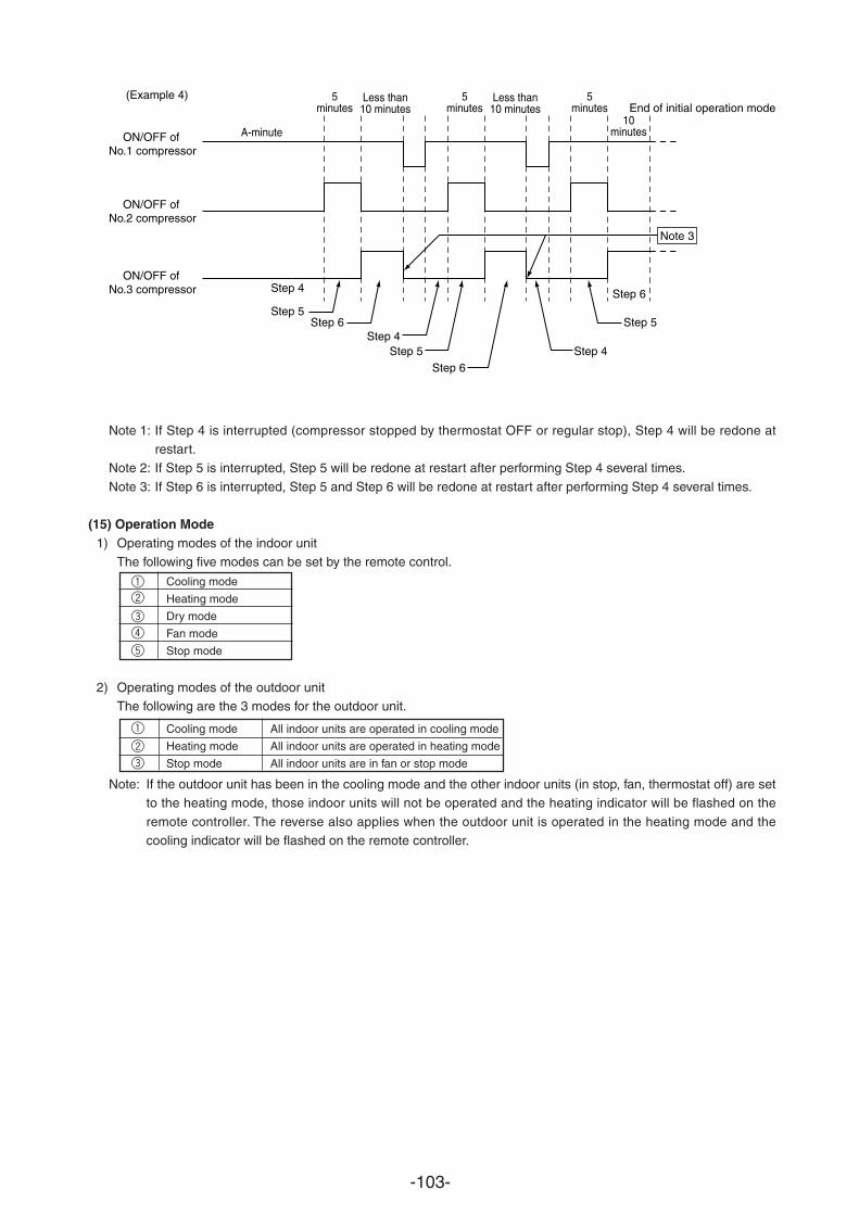
-103-
Note 1: If Step 4 is interrupted (compressor stopped by thermostat OFF or regular stop), Step 4 will be redone atrestart.
Note 2: If Step 5 is interrupted, Step 5 will be redone at restart after performing Step 4 several times.
Note 3: If Step 6 is interrupted, Step 5 and Step 6 will be redone at restart after performing Step 4 several times.
(15) Operation Mode1) Operating modes of the indoor unit
The following five modes can be set by the remote control.
Cooling mode
Heating mode
Dry mode
Fan mode
Stop mode
2) Operating modes of the outdoor unitThe following are the 3 modes for the outdoor unit.
1
1
2
3
4
5
2
3
Cooling mode All indoor units are operated in cooling mode
Heating mode All indoor units are operated in heating mode
Stop mode All indoor units are in fan or stop mode
Note: If the outdoor unit has been in the cooling mode and the other indoor units (in stop, fan, thermostat off) are setto the heating mode, those indoor units will not be operated and the heating indicator will be flashed on the
remote controller. The reverse also applies when the outdoor unit is operated in the heating mode and thecooling indicator will be flashed on the remote controller.
(Example 4)
A-minute
Less than10 minutes
Step 5Step 6 Step 5
Step 6
Step 4Step 5 Step 4
Step 6
10minutes
5minutes
Less than10 minutes
5minutes
5minutes
ON/OFF of No.1 compressor
ON/OFF of No.2 compressor
ON/OFF of No.3 compressor
End of initial operation mode
Note 3
Step 4
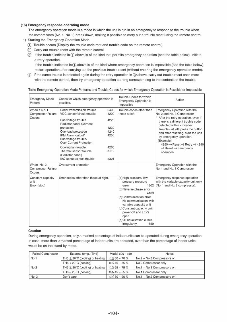
-104-
(16) Emergency response operating modeThe emergency operation mode is a mode in which the unit is run in an emergency to respond to the trouble when
compressors (No. 1, No. 2) break down, making it possible to carry out a trouble reset using the remote control.the
1) Starting the Emergency Operation Mode1 Trouble occurs (Display the trouble code root and trouble code on the remote control).2 Carry out trouble reset with the remote control.
3 If the trouble indicted in 1 above is of the kind that permits emergency operation (see the table below), initiate a retry operation.If the trouble indicated in 1 above is of the kind where emergency operation is impossible (see the table below),
restart operation after carrying out the previous trouble reset (without entering the emergency operation mode).4 If the same trouble is detected again during the retry operation in 3 above, carry out trouble reset once more
with the remote control, then try emergency operation starting corresponding to the contents of the trouble.
Table Emergency Operation Mode Patterns and Trouble Codes for which Emergency Operation is Possible or Impossible
Codes for which emergency operation ispossible.
Overcurrent protection
Error codes other than those at right.
Emergency ModePattern
When a No. 1Compressor FailureOccurs
When No. 2Compressor FailureOccurs
Constant capacityunitError (stop)
Trouble Codes for whichEmergency Operation isImpossible
Trouble codes other thanthose at left.
(a)High pressure/ low-pressure pressureerror 1302
(b)Reverse phase error4103
(c)Communication errorNo communication withvariable capacity unit
(d)Constant capacity unitpower-off and LEV2open
(e)Oil equalization circuitirregularity 1559
Action
Emergency Operation with theNo. 2 and No. 3 Compressor * After the retry operation, even if
there is a different trouble codedetected within <InverterTrouble> at left, press the buttonand after resetting, start the unitby emergency operation.[Example]
4250 Reset Retry 4240Reset Emergency
operation
Emergency Operation with theNo. 1 and No. 3 Compressor
Emergency response operationwith the variable capacity unit only(No. 1 and No. 2 compressor).
Failed Compressor External temp. (TH6) Model 600 - 750 Notes
No.1 TH6 20˚C (cooling) or heating 60 ~ 70 % No.2 + No.3 Compressors on
TH6 < 20˚C (cooling) 45 ~ 55 % No.2 Compressor only
No.2 TH6 20˚C (cooling) or heating 65 ~ 75 % No.1 + No.3 Compressors on
TH6 < 20˚C (cooling) 45 ~ 55 % No.1 Compressor only
No. 3 Don’t care 80 ~ 90 % No.1 + No.2 Compressors on
CautionDuring emergency operation, only marked percentage of indoor units can be operated during emergency operation.In case, more than marked percentage of indoor units are operated, over than the percentage of indoor unitswould be on the stand-by mode.
Serial transmission trouble 0403VDC sensor/circuit trouble 4200
Bus voltage trouble 4220Radiator panel overheatprotection 4230Overload protection 4240
4250IPM Alarm output/Bus voltage trouble/Over Current Protection
Cooling fan trouble 4260Thermal sensor trouble(Radiator panel)
5110
IAC sensor/circuit trouble 5301

-105-
2) Terminating Emergency Response Operation Mode(Termination Conditions)When one of the following conditions is met, emergency operation mode is terminated.
1 Cumulative compressor operation time in the cooling mode exceeds 4 hours.2 Cumulative compressor operation time in the heating mode exceeds 2 hours.3 Emergency operation mode trouble detected.
(Control During and After Termination)• During and after termination, the compressor will be stopped and a repeat error code will be flashed on the
remote controller.• If there is a repeat trouble reset during termination, retry operations will start by repeating steps 1 to 4 in 1).
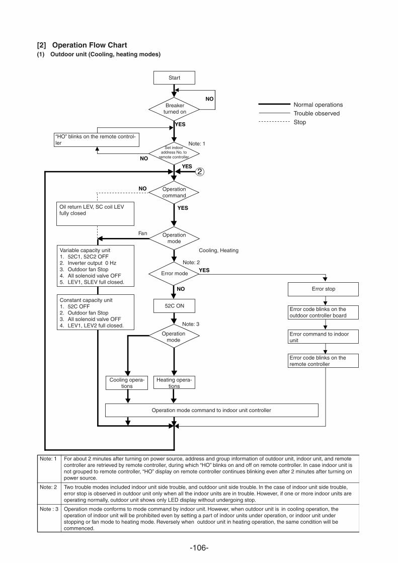
-106-
[2] Operation Flow Chart(1) Outdoor unit (Cooling, heating modes)
Note: 1 For about 2 minutes after turning on power source, address and group information of outdoor unit, indoor unit, and remotecontroller are retrieved by remote controller, during which “HO” blinks on and off on remote controller. In case indoor unit isnot grouped to remote controller, “HO” display on remote controller continues blinking even after 2 minutes after turning onpower source.
Note: 2 Two trouble modes included indoor unit side trouble, and outdoor unit side trouble. In the case of indoor unit side trouble,error stop is observed in outdoor unit only when all the indoor units are in trouble. However, if one or more indoor units areoperating normally, outdoor unit shows only LED display without undergoing stop.
Note : 3 Operation mode conforms to mode command by indoor unit. However, when outdoor unit is in cooling operation, the operation of indoor unit will be prohibited even by setting a part of indoor units under operation, or indoor unit understopping or fan mode to heating mode. Reversely when outdoor unit in heating operation, the same condition will becommenced.
YES
NO
YES
NO
YES
YES
NO
NO
2
Normal operationsTrouble observed
Stop
“HO” blinks on the remote control-ler
Oil return LEV, SC coil LEVfully closed
Variable capacity unit1. 52C1, 52C2 OFF2. Inverter output 0 Hz3. Outdoor fan Stop4. All solenoid valve OFF5. LEV1, SLEV full closed.
Constant capacity unit1. 52C OFF2. Outdoor fan Stop3. All solenoid valve OFF4. LEV1, LEV2 full closed.
Breakerturned on
Error code blinks on theoutdoor controller board
Start
Set indooraddress No. to
remote controller
Operationcommand
Operationmode
Error mode
52C ON
Operationmode
Heating opera-tions
Cooling opera-tions
Operation mode command to indoor unit controller
Error stop
Error command to indoorunit
Note: 1
Note: 2
Cooling, Heating
Fan
Note: 3
Error code blinks on theremote controller
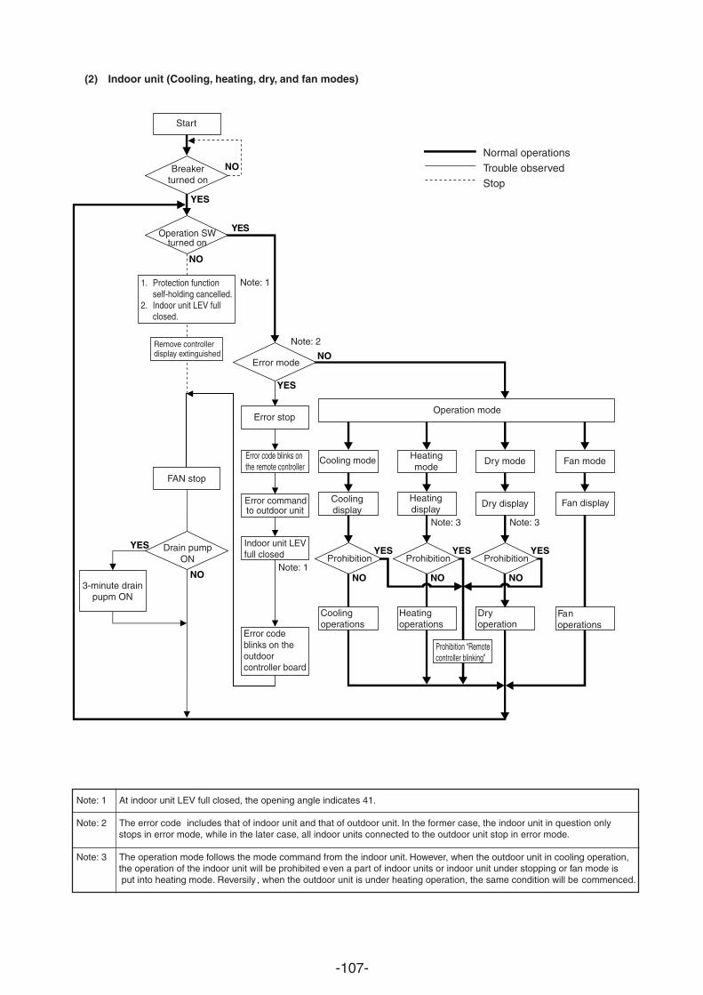
-107-
(2) Indoor unit (Cooling, heating, dry, and fan modes)
Note: 1 At indoor unit LEV full closed, the opening angle indicates 41.
Note: 2 The error code includes that of indoor unit and that of outdoor unit. In the former case, the indoor unit in question onlystops in error mode, while in the later case, all indoor units connected to the outdoor unit stop in error mode.
Note: 3 The operation mode follows the mode command from the indoor unit. However, when the outdoor unit in cooling operation, the operation of the indoor unit will be prohibited even a part of indoor units or indoor unit under stopping or fan mode is put into heating mode. Reversily , when the outdoor unit is under heating operation, the same condition will be commenced.
YES
NO
YES
NO
YES
NO
YES
NO
YES
NO
YES
NO
YES
NO
Normal operationsTrouble observedStop
Start
Breakerturned on
Operation SWturned on
1. Protection functionself-holding cancelled.
2. Indoor unit LEV fullclosed.
Remove controllerdisplay extinguished
3-minute drainpupm ON
FAN stop
Drain pumpON
Error mode
Error stop
Error code blinks onthe remote controller
Indoor unit LEVfull closed
Error codeblinks on theoutdoorcontroller board
Operation mode
Heatingmode
Coolingdisplay
Cooling mode Dry mode
Heatingdisplay
Fan mode
Fan displayDry display
Prohibition Prohibition
Heatingoperations
Coolingoperations
Prohibition
Dryoperation
Fanoperations
Prohibition “Remotecontroller blinking”
Note: 3 Note: 3
Note: 1
Note: 2
Note: 1
Error commandto outdoor unit
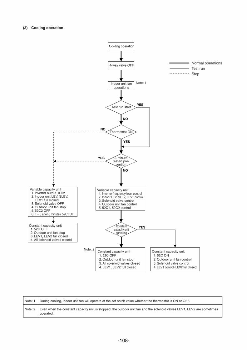
-108-
YES
NO
YES
YES
YES
NO
NO
(3) Cooling operation
Normal operations
Test runStop
Cooling operation
4-way valve OFF
Indoor unit fanoperations
Test run start
Thermostat ON
3-minuterestart pre-
vention
Variable capacity unit1. Inverter frequency level control2. Indoor LEV, SLEV, LEV1 control3. Solenoid valve control4. Outdoor unit fan control5. 52C1, 52C2 control
Variable capacity unit1. Inverter output 0 Hz2. Indoor unit LEV, SLEV,
LEV1 full closed3. Solenoid valve OFF4. Outdoor unit fan stop5. 52C2 OFF6. F = 0 after 6 minutes 52C1 OFF
Constant capacity unit1. 52C OFF2. Outdoor unit fan stop3. LEV1, LEV2 full closed4. All solenoid valves closed
Constantcapacity unit
operation
Constant capacity unit1. 52C OFF2. Outdoor unit fan stop3. All solenoid valves closed4. LEV1, LEV2 full closed
Constant capacity unit1. 52C ON2. Outdoor unit fan control3. Solenoid valve control4. LEV1 control (LEV2 full closed)
Note: 1 During cooling, indoor unit fan will operate at the set notch value whether the thermostat is ON or OFF.
Note: 2 Even when the constant capacity unit is stopped, the outdoor unit fan and the solenoid valves LEV1, LEV2 are sometimesoperated.
Note: 2
Note: 1
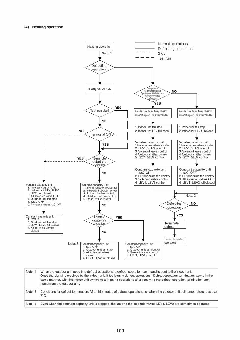
-109-
(4) Heating operation
Note: 1 When the outdoor unit goes into defrost operations, a defrost operation command is sent to the indoor unit.Once the signal is received by the indoor unit, it too begins defrost operations. Defrost operation termination works in thesame manner, with the indoor unit switching to heating operations after receiving the defrost operation termination com-mand from the outdoor unit.
Note: 2 Conditions for defrost termination: After 15 minutes of defrost operations, or when the outdoor unit coil temperature is above7˚C.
Note: 3 Even when the constant capacity unit is stopped, the fan and the solenoid valves LEV1, LEV2 are sometimes operated.
YES
NO
YES
YES
YES
YES
YES
NO
NO
NO
NO
NO
NO
Normal operationsDefrosting operationsStopTest run
Heating operation
Note: 1
Defrostingoperation
4-way valve ON
Test run start
Thermostat ON
3-minuterestart pre-
vention
During constantcapacity unit operation or
Operation over 30 minutes beforestopping the constant
capacity unit.
1. Indoor unit fan stop.2. Indoor unit LEV full open.
Variable capacity unit 4-way valve OFFConstant capacity unit 4-way valve ON
Variable capacity unit1. Inverter frequency at defrost control2. LEV1, SLEV control3. Solenoid valve control4. Outdoor unit fan control5. 52C1, 52C2 control
Constant capacity unit1. 52C ON2. Outdoor unit fan control3. Solenoid valve control4. LEV1, LEV2 control
1. Indoor unit fan stop.2. Indoor unit LEV full closed.
Variable capacity unit 4-way valve OFFConstant capacity unit 4-way valve ON
Variable capacity unit1. Inverter frequency at defrost control2. LEV1, SLEV control3. Solenoid valve control4. Outdoor unit fan control5. 52C1, 52C2 control
Constant capacity unit1. 52C OFF2. Outdoor unit fan control3. All solenoid valves OFF4. LEV1, LEV2 full closed
Terminatedefrost
Return to heatingoperations
Note: 2
Note: 3
Defrostingoperation
Variable capacity unit1. Inverter frequency level control2. Indoor LEV, SLEV, LEV1 control3. Solenoid valve control4. Outdoor unit fan control5. 52C1, 52C2 control
Variable capacity unit1. Inverter output 0 Hz2. Indoor unit LEV, SLEV,
LEV1 full closed3. All solenoid valve OFF4. Outdoor unit fan stop5. 52C2 OFF6. F = 0 after 6 minutes 52C1 OFF
Constant capacity unit1. 52C OFF2. Outdoor unit fan stop3. LEV1, LEV2 full closed4. All solenoid valves
closed
Constantcapacity unit
operation
Constant capacity unit1. 52C OFF2. Outdoor unit fan stop3. All solenoid valves
closed4. LEV1, LEV2 full closed
Constant capacity unit1. 52C ON2. Outdoor unit fan control3. Solenoid valve control4. LEV1, LEV2 control
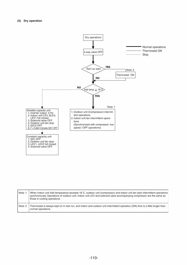
-110-
(5) Dry operation
Note: 1 When indoor unit inlet temperature exceeds 18˚C, outdoor unit (compressor) and indoor unit fan start intermittent operationssynchronously. Operations of outdoor unit, indoor unit LEV and solenoid valve accompanying compressor are the same asthose in cooling operations.
Note: 2 Thermostat is always kept on in test run, and indoor and outdoor unit intermittent operation (ON) time is a little longer thannormal operations.
YES
NO
YES
NO
Normal operationsThermostat ONStop
Dry operations
4-way valve OFF
Test run start Note: 2
Thermostat ON
Inlet temp. 18˚C
Note: 1Variable capacity unit1. Inverter output 0 Hz2. Indoor unit LEV, SLEV,
LEV1 full closed3. Solenoid valve OFF4. Outdoor unit fan stop5. 52C2 OFF6. F = 0 after 6 minutes 52C1 OFF
Constant capacity unit1. 52C OFF2. Outdoor unit fan stop3. LEV1, LEV2 full closed4. Solenoid valve OFF
1. Outdoor unit (Compressor) intermit-tent operations
2. Indoor unit fan intermittent opera-tions(Synchronized with compressor: lowspeed / OFF operations)
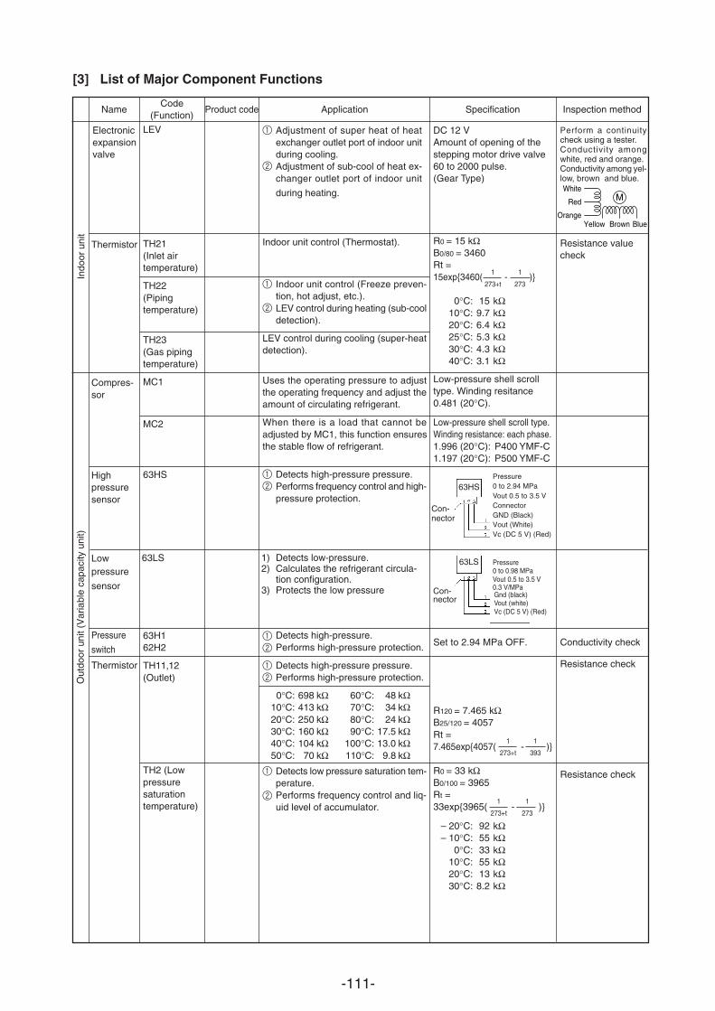
-111-
1 Adjustment of super heat of heatexchanger outlet port of indoor unitduring cooling.
2 Adjustment of sub-cool of heat ex-changer outlet port of indoor unit
during heating.
Indoor unit control (Thermostat).
1 Indoor unit control (Freeze preven-tion, hot adjust, etc.).
2 LEV control during heating (sub-cooldetection).
LEV control during cooling (super-heatdetection).
Uses the operating pressure to adjustthe operating frequency and adjust theamount of circulating refrigerant.
When there is a load that cannot beadjusted by MC1, this function ensuresthe stable flow of refrigerant.
[3] List of Major Component Functions
NameCode
(Function)
Electronicexpansionvalve
Thermistor
Compres-sor
Out
door
uni
t (V
aria
ble
capa
city
uni
t)
Inspection method
DC 12 VAmount of opening of thestepping motor drive valve60 to 2000 pulse.(Gear Type)
R0 = 15 kΩB0/80 = 3460Rt =15exp3460( - )
0°C: 15 kΩ10°C: 9.7 kΩ20°C: 6.4 kΩ25°C: 5.3 kΩ30°C: 4.3 kΩ40°C: 3.1 kΩ
Low-pressure shell scrolltype. Winding resitance0.481 (20°C).
Low-pressure shell scroll type.Winding resistance: each phase.1.996 (20°C): P400 YMF-C1.197 (20°C): P500 YMF-C
1
273+t
1
273
1
273+t
1
393
ApplicationProduct code Specification
Indo
or u
nit
LEV
TH21(Inlet airtemperature)
TH22(Pipingtemperature)
TH23(Gas pipingtemperature)
MC1
MC2
White
Red
Yellow Brown BlueOrange
M
Perform a continuitycheck using a tester.Conductivity amongwhite, red and orange.Conductivity among yel-low, brown and blue.
Resistance valuecheck
Con-nector
1
273+t
1
273
63HS
Pressure
0.3 V/MPaGnd (black)Vout (white)Vc (DC 5 V) (Red)
Con-nector
63LS
R120 = 7.465 kΩB25/120 = 4057Rt =7.465exp4057( - )
R0 = 33 kΩB0/100 = 3965Rt =33exp3965( - )
– 20°C: 92 kΩ– 10°C: 55 kΩ
0°C: 33 kΩ10°C: 55 kΩ20°C: 13 kΩ30°C: 8.2 kΩ
1 Detects high-pressure pressure.2 Performs frequency control and high-
pressure protection.
1) Detects low-pressure.2) Calculates the refrigerant circula-
tion configuration.3) Protects the low pressure
Detects high-pressure.Performs high-pressure protection.
Detects high-pressure pressure.Performs high-pressure protection.
0°C: 698 kΩ 60°C: 48 kΩ10°C: 413 kΩ 70°C: 34 kΩ20°C: 250 kΩ 80°C: 24 kΩ30°C: 160 kΩ 90°C: 17.5 kΩ40°C: 104 kΩ 100°C: 13.0 kΩ50°C: 70 kΩ 110°C: 9.8 kΩDetects low pressure saturation tem-perature.Performs frequency control and liq-uid level of accumulator.
Highpressuresensor
Lowpressure
sensor
Pressure
switch
Thermistor
63HS
63LS
63H162H2
TH11,12(Outlet)
TH2 (Lowpressuresaturationtemperature)
Conductivity check
Resistance check
Resistance check
0 to 0.98 MPaVout 0.5 to 3.5 V
Set to 2.94 MPa OFF.
Pressure
Vout 0.5 to 3.5 VConnectorGND (Black)Vout (White)Vc (DC 5 V) (Red)
0 to 2.94 MPa
1
2
1
2
1
2
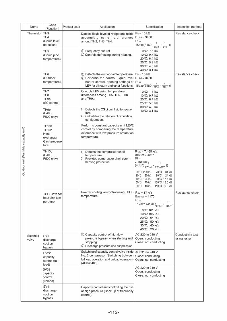
-112-
Detects the outdoor air temperature.Performs fan control, liquid levelheater control, opening settings ofLEV for oil return and other functions.
Thermistor
R0 = 15 kΩB1/80 = 3460Rt =15exp3460( - )
0°C: 15 kΩ10°C: 9.7 kΩ20°C: 6.4 kΩ25°C: 5.3 kΩ30°C: 4.3 kΩ40°C: 3.1 kΩ
Resistance checkTH6(Outdoortemperature)
TH7TH8TH9a(SC control)
(P400, P500 only)
NameCode
(Function)Inspection methodApplicationProduct code Specification
1
273+t
1
273
1
273+t
1
273
1273+t
1273+120
1
273+t
1
323
Resistance checkTH3TH4(Liquid leveldetection)
TH5(Liquid pipetemperature)
Detects liquid level of refrigerant insideaccumulator using the differencesamong TH2, TH3, TH4.
1 Frequency control.2 Controls defrosting during heating.
Resistance check
Conductivity testusing tester
TH10c(P400, P500 only)
1) Detects the compressor shelltemperature.
2) Provides compressor shell over-heating protection.
Inverter cooling fan control using THHStemperature.
1 Capacity control of high/lowpressure bypass when starting andstopping.
2 Discharge pressure rise suppression.
Switching of capacity control valve insideNo. 2 compressor (Switching betweenfull load operation and unload operation)(All but 400).
Capacity control and controlling the riseof high-pressure (Back-up of frequencycontrol).
R120 = 7.465 kΩB25/120 = 4057Rt =7.465exp4057( - )
20°C: 250 kΩ 70°C: 34 kΩ30°C: 160 kΩ 80°C: 24 kΩ40°C: 104 kΩ 90°C: 17.5 kΩ50°C: 70 kΩ 100°C: 13.0 kΩ60°C: 48 kΩ 110°C: 9.8 kΩ
R50 = 17 kΩB25/120 = 4170Rt = 17exp 4170 ( - )
0°C: 181 kΩ10°C: 105 kΩ20°C: 64 kΩ25°C: 50 kΩ30°C: 40 kΩ40°C: 26 kΩ
AC 220 to 240 VOpen : conductingClose: not conducting
AC 220 to 240 VClose: conductingOpen : not conducting
AC 220 to 240 VOpen : conductingClose: not conducting
THHS inverterheat sink tem-perature
SV1discharge-suctionbypass
SV22capacitycontrol (fullload)
SV32capacitycontrol(unload)
SV4discharge-suctionbypass
TH9b
Controls LEV using temperature differences among TH5, TH7, TH8 and TH9a.
1) Detects the CS circuit fluid tempera-ture.
2) Calculates the refrigerant circulationconfiguration.
R0 = 15 kΩB1/80 = 3460Rt =15exp3460( - )
0°C: 15 kΩ10°C: 9.7 kΩ20°C: 6.4 kΩ25°C: 5.3 kΩ30°C: 4.3 kΩ40°C: 3.1 kΩ
Solenoidvalve
Out
door
uni
t (V
aria
ble
capa
city
uni
t)
1
2
Performs constant capacity unit LEV2control by comparing the temperaturedifference with low pressure saturationtemperature.
TH10aTH10bHeatexchangerGas tempera-ture
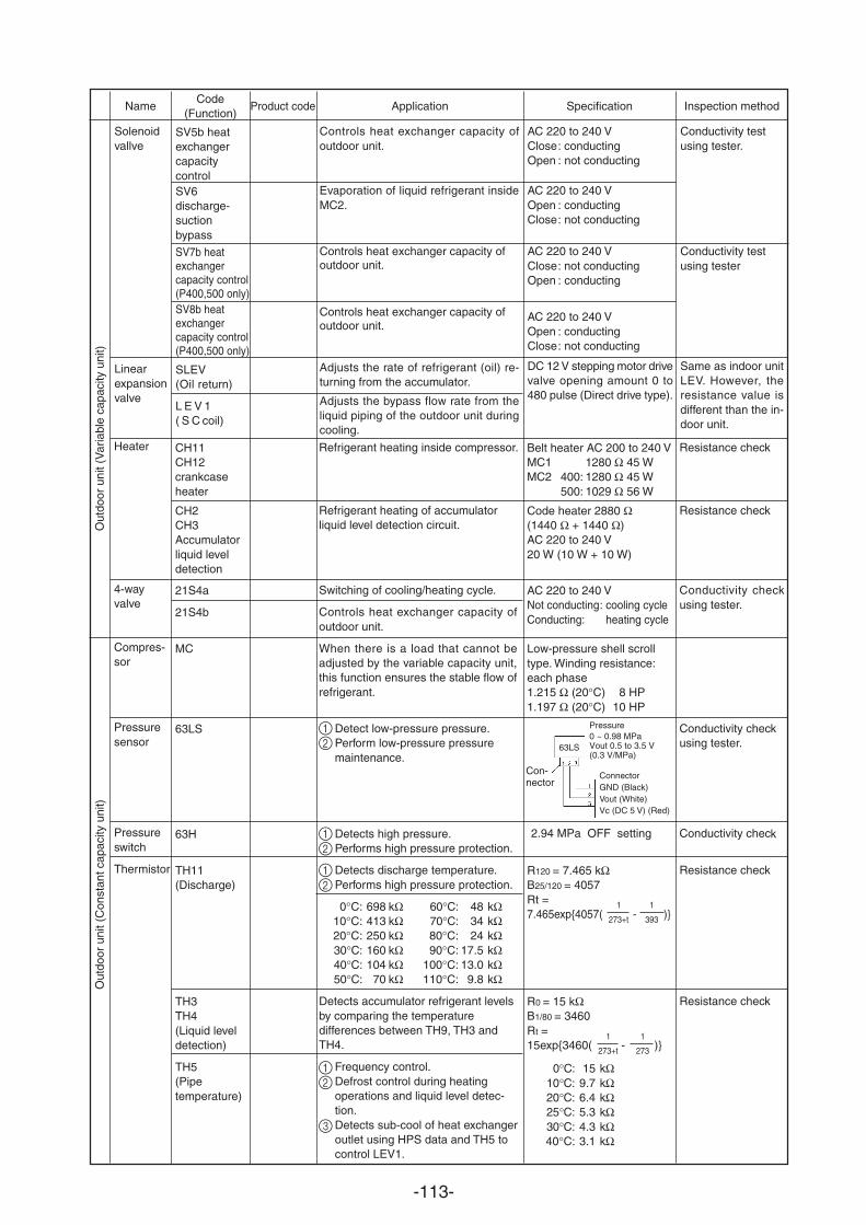
-113-
Resistance check
Resistance check
Conductivity checkusing tester.
Conductivity checkusing tester.
Conductivity check
Resistance check
Resistance check
Belt heater AC 200 to 240 VMC1 1280 Ω 45 WMC2 400: 1280 Ω 45 W
500: 1029 Ω 56 W
Code heater 2880 Ω(1440 Ω + 1440 Ω)AC 220 to 240 V20 W (10 W + 10 W)
AC 220 to 240 VNot conducting: cooling cycleConducting: heating cycle
Low-pressure shell scrolltype. Winding resistance:each phase1.215 Ω (20°C) 8 HP1.197 Ω (20°C) 10 HP
2.94 MPa OFF setting
R120 = 7.465 kΩB25/120 = 4057Rt =7.465exp4057( - )
R0 = 15 kΩB1/80 = 3460Rt =15exp3460( - )
0°C: 15 kΩ10°C: 9.7 kΩ20°C: 6.4 kΩ25°C: 5.3 kΩ30°C: 4.3 kΩ40°C: 3.1 kΩ
Refrigerant heating inside compressor.
Refrigerant heating of accumulatorliquid level detection circuit.
Switching of cooling/heating cycle.
Controls heat exchanger capacity ofoutdoor unit.
When there is a load that cannot beadjusted by the variable capacity unit,this function ensures the stable flow ofrefrigerant.
Detect low-pressure pressure.Perform low-pressure pressuremaintenance.
Detects high pressure.Performs high pressure protection.
Detects discharge temperature.Performs high pressure protection.
0°C: 698 kΩ 60°C: 48 kΩ10°C: 413 kΩ 70°C: 34 kΩ20°C: 250 kΩ 80°C: 24 kΩ30°C: 160 kΩ 90°C: 17.5 kΩ40°C: 104 kΩ 100°C: 13.0 kΩ50°C: 70 kΩ 110°C: 9.8 kΩ
Detects accumulator refrigerant levelsby comparing the temperaturedifferences between TH9, TH3 andTH4.
Frequency control.Defrost control during heatingoperations and liquid level detec-tion.Detects sub-cool of heat exchangeroutlet using HPS data and TH5 tocontrol LEV1.
CH11CH12crankcaseheater
CH2CH3Accumulatorliquid leveldetection
21S4a
21S4b
MC
63LS
63H
TH11(Discharge)
TH3TH4(Liquid leveldetection)
TH5(Pipetemperature)
Heater
4-wayvalve
Compres-sor
Pressuresensor
Pressureswitch
Thermistor
NameCode
(Function)Inspection methodApplicationProduct code Specification
Out
door
uni
t (V
aria
ble
capa
city
uni
t)O
utdo
or u
nit (
Con
stan
t cap
acity
uni
t)
1
273+t
1
393
1
273+t
1
273
Con-nector
Pressure
(0.3 V/MPa)63LS
ConnectorGND (Black)Vout (White)Vc (DC 5 V) (Red)
Solenoidvallve
Linearexpansionvalve
SV5b heatexchangercapacitycontrolSV6discharge-suctionbypass
SLEV (Oil return)
L E V 1 ( S C coil)
Controls heat exchanger capacity ofoutdoor unit.
Evaporation of liquid refrigerant insideMC2.
Adjusts the rate of refrigerant (oil) re-turning from the accumulator.
Adjusts the bypass flow rate from theliquid piping of the outdoor unit duringcooling.
AC 220 to 240 VClose: conductingOpen : not conducting
AC 220 to 240 VOpen : conductingClose: not conducting
DC 12 V stepping motor drivevalve opening amount 0 to480 pulse (Direct drive type).
Same as indoor unitLEV. However, theresistance value isdifferent than the in-door unit.
Conductivity testusing tester
SV7b heat exchanger capacity control(P400,500 only)SV8b heat exchanger capacity control(P400,500 only)
Controls heat exchanger capacity of outdoor unit.
Controls heat exchanger capacity of outdoor unit.
AC 220 to 240 VClose: not conductingOpen : conducting
AC 220 to 240 VOpen : conductingClose: not conducting
Conductivity testusing tester
.
0 ~ 0.98 MPaVout 0.5 to 3.5 V
12
12
12
12
3
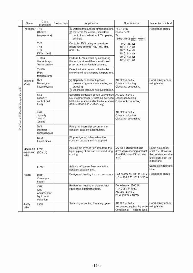
-114-
SV1Discharge –Suction Bypass
SV2capacitycontrol (fullload)
SV3capacitycontrol(unload)
SV4Discharge –Suction Bypass
SV5bLiquid pipes
LEV1(SC coil)
LEV2
CH11Crankcaseheater
CH2CH3Accumulatorliquid leveldetection
21S4
Conductivity checkusing tester.
Same as outdoorunit LEV. Howeverthe resistance valueis different than theindoor unit.
Same as indoor unitLEV.
Resistance check
Conductivity checkusing tester.
AC 220 to 240 VOpen: conductingClose: not conducting
AC 220 to 240 VClose: conductingOpen: not conducting
AC 220 to 240 VOpen: conductionClose: not conducting
DC 12 V stepping motordrive valve opening amount0 to 480 pulse (Direct drivetype)
Belt heater AC 200 to 240 VMC ··· 200, 250: 1029 Ω 56 W
Code heater 2880 Ω(1440 Ω + 1440 Ω)AC 220 to 240 V20 W (10 W + 10 W)
AC 220 to 240 VNot conducting: heating cycleConducting: cooling cycle
Capacity control of high/lowpressure bypass when starting andstopping.Discharge pressure rise suppression.
Switching of capacity control valve insideNo. 2 compressor (Switching betweenfull load operation and unload operation)(PUHN-P200·250 YMF-C only).
Raise the internal pressure of theconstant capacity accumulator.
Stop refrigerant inflow when theconstant capacity unit is stopped.
Adjusts the bypass flow rate from theliquid piping of the outdoor unit duringcooling.
Adjusts refrigerant flow rate in theconstant capacity unit.
Refrigerant heating inside compressor.
Refrigerant heating of accumulatorliquid level detection circuit.
Switching of cooling / heating cycle.
Thermistor
SolenoidValve
Electronicexpansionvalve
Heater
4-wayvalve
R0 = 15 kΩB0/80 = 3460Rt =15exp3460( - )
0°C: 15 kΩ10°C: 9.7 kΩ20°C: 6.4 kΩ25°C: 5.3 kΩ30°C: 4.3 kΩ40°C: 3.1 kΩ
NameCode
(Function)Inspection methodApplicationProduct code Specification
Out
door
uni
t (C
onst
ant c
apac
ity u
nit)
TH6(Outdoortemperature)
TH7TH8TH9(SC control)
TH10aHeat exchangerGas temperature
TH10b(Pipetemperature)
Detects the outdoor air temperature.Performs fan control, liquid levelcontrol, and oil-return LEV openingsettings.
Controls LEV1 using temperaturedifferences among TH5, TH7, TH8,and TH9.
Perform LEV2 control by comparingthe temperature difference with lowpressure saturation temperature.
Detect failure to open ball-valve bychecking oil balance pipe temperature.
Resistance check
1
273+t
1
273
12
2
1
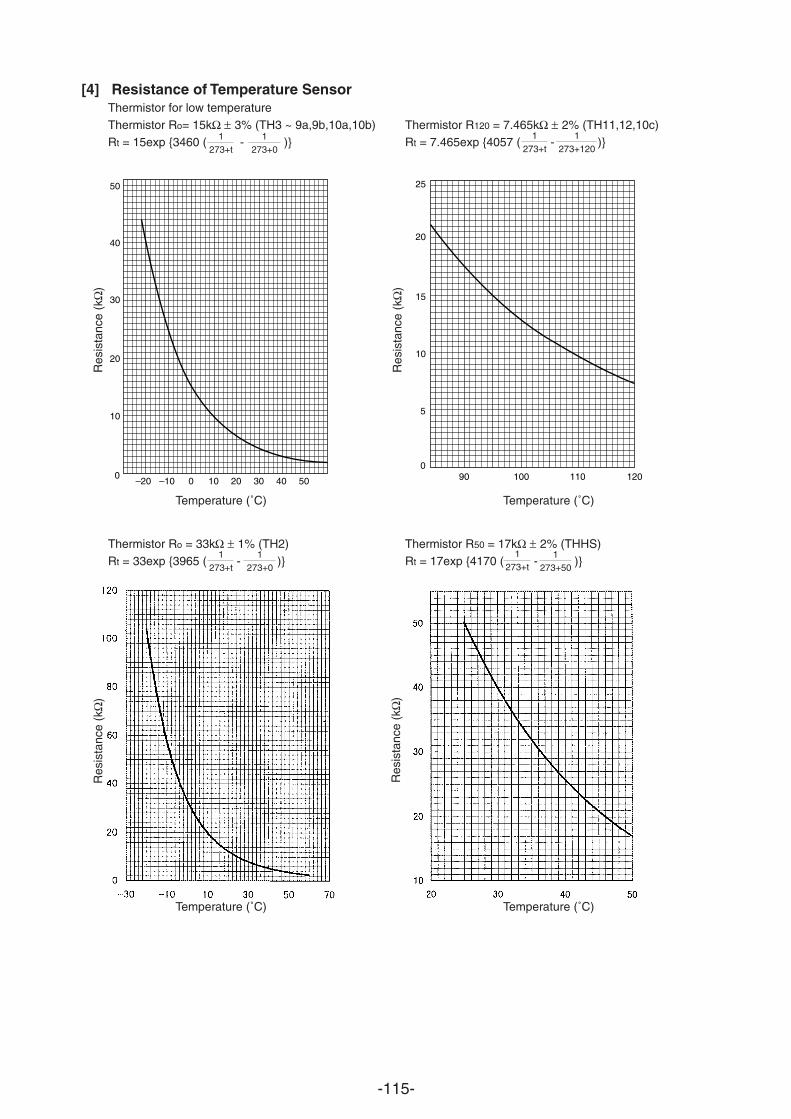
-115-
[4] Resistance of Temperature SensorThermistor for low temperatureThermistor Ro= 15kΩ ± 3% (TH3 ~ 9a,9b,10a,10b) Thermistor R120 = 7.465kΩ ± 2% (TH11,12,10c)Rt = 15exp 3460 ( - ) Rt = 7.465exp 4057 ( - )
Thermistor Ro = 33kΩ ± 1% (TH2) Thermistor R50 = 17kΩ ± 2% (THHS)Rt = 33exp 3965 ( - ) Rt = 17exp 4170 ( - )
50
40
30
20
10
0–20 –10 10 20 30 40 500
25
20
15
10
5
090 100 110 120
1273+t
1273+t
1273+t
1273+t
1273+50
Temperature (˚C) Temperature (˚C)
Temperature (˚C) Temperature (˚C)
Res
ista
nce
(kΩ
)
Res
ista
nce
(kΩ
)R
esis
tanc
e (k
Ω)
Res
ista
nce
(kΩ
)
1273+0
1273+120
1273+0
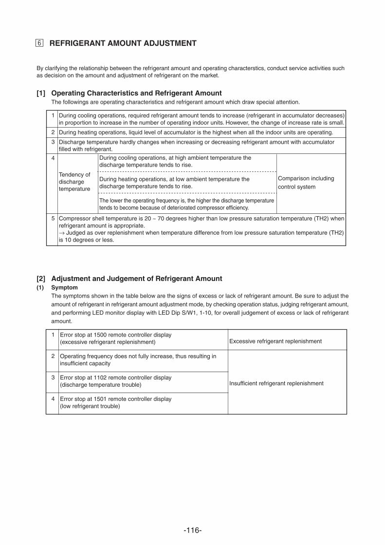
-116-
1
2
3
4
5
During cooling operations, required refrigerant amount tends to increase (refrigerant in accumulator decreases)in proportion to increase in the number of operating indoor units. However, the change of increase rate is small.
During heating operations, liquid level of accumulator is the highest when all the indoor units are operating.
Discharge temperature hardly changes when increasing or decreasing refrigerant amount with accumulatorfilled with refrigerant.
Compressor shell temperature is 20 ~ 70 degrees higher than low pressure saturation temperature (TH2) whenrefrigerant amount is appropriate.→ Judged as over replenishment when temperature difference from low pressure saturation temperature (TH2)is 10 degrees or less.
Tendency ofdischargetemperature
During cooling operations, at high ambient temperature the discharge temperature tends to rise.
During heating operations, at low ambient temperature the discharge temperature tends to rise.
The lower the operating frequency is, the higher the discharge temperaturetends to become because of deteriorated compressor efficiency.
Comparison including
control system
§ REFRIGERANT AMOUNT ADJUSTMENT
[1] Operating Characteristics and Refrigerant AmountThe followings are operating characteristics and refrigerant amount which draw special attention.
[2] Adjustment and Judgement of Refrigerant Amount(1) Symptom
The symptoms shown in the table below are the signs of excess or lack of refrigerant amount. Be sure to adjust the
amount of refrigerant in refrigerant amount adjustment mode, by checking operation status, judging refrigerant amount,and performing LED monitor display with LED Dip S/W1, 1-10, for overall judgement of excess or lack of refrigerantamount.
1
2
3
4
Error stop at 1500 remote controller display(excessive refrigerant replenishment)
Operating frequency does not fully increase, thus resulting ininsufficient capacity
Error stop at 1102 remote controller display(discharge temperature trouble)
Error stop at 1501 remote controller display(low refrigerant trouble)
Excessive refrigerant replenishment
Insufficient refrigerant replenishment
By clarifying the relationship between the refrigerant amount and operating characterstics, conduct service activities such as decision on the amount and adjustment of refrigerant on the market.
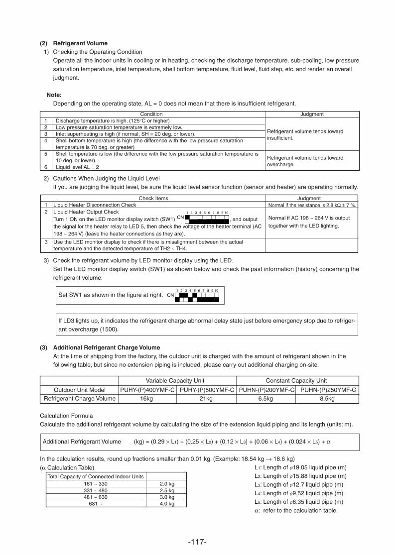
-117-
3) Check the refrigerant volume by LED monitor display using the LED.Set the LED monitor display switch (SW1) as shown below and check the past information (history) concerning the
refrigerant volume.
Set SW1 as shown in the figure at right.
If LD3 lights up, it indicates the refrigerant charge abnormal delay state just before emergency stop due to refriger-ant overcharge (1500).
Judgment
Refrigerant volume tends towardinsufficient.
Refrigerant volume tends towardovercharge.
Check Items Judgment
1 2 3 4 5 6 7 8 9 10
ON
Condition1 Discharge temperature is high. (125°C or higher)2 Low pressure saturation temperature is extremely low.3 Inlet superheating is high (if normal, SH = 20 deg. or lower).4 Shell bottom temperature is high (the difference with the low pressure saturation
temperature is 70 deg. or greater)5 Shell temperature is low (the difference with the low pressure saturation temperature is
10 deg. or lower).6 Liquid level AL = 2
Normal if the resistance is 2.8 kΩ ± 7 %.
Normal if AC 198 ~ 264 V is output
together with the LED lighting.
1 Liquid Heater Disconnection Check2 Liquid Heater Output Check
Turn 1 ON on the LED monitor display switch (SW1) , and outputthe signal for the heater relay to LED 5, then check the voltage of the heater terminal (AC198 ~ 264 V) (leave the heater connections as they are).
3 Use the LED monitor display to check if there is misalignment between the actualtemperature and the detected temperature of TH2 ~ TH4.
(2) Refrigerant Volume1) Checking the Operating Condition
Operate all the indoor units in cooling or in heating, checking the discharge temperature, sub-cooling, low pressure
saturation temperature, inlet temperature, shell bottom temperature, fluid level, fluid step, etc. and render an overalljudgment.
Note:Depending on the operating state, AL = 0 does not mean that there is insufficient refrigerant.
2) Cautions When Judging the Liquid LevelIf you are judging the liquid level, be sure the liquid level sensor function (sensor and heater) are operating normally.
1 2 3 4 5 6 7 8 9 10
ON
(3) Additional Refrigerant Charge VolumeAt the time of shipping from the factory, the outdoor unit is charged with the amount of refrigerant shown in thefollowing table, but since no extension piping is included, please carry out additional charging on-site.
Variable Capacity Unit Constant Capacity Unit
Outdoor Unit Model PUHY-(P)400YMF-C PUHY-(P)500YMF-C PUHN-(P)200YMF-C PUHN-(P)250YMF-CRefrigerant Charge Volume 16kg 21kg 6.5kg 8.5kg
Calculation FormulaCalculate the additional refrigerant volume by calculating the size of the extension liquid piping and its length (units: m).
Additional Refrigerant Volume (kg) = (0.29 × L1) + (0.25 × L2) + (0.12 × L3) + (0.06 × L4) + (0.024 × L5) + α
In the calculation results, round up fractions smaller than 0.01 kg. (Example: 18.54 kg → 18.6 kg)L1: Length of ø19.05 liquid pipe (m)L2: Length of ø15.88 liquid pipe (m)
L3: Length of ø12.7 liquid pipe (m)L4: Length of ø9.52 liquid pipe (m)L5: Length of ø6.35 liquid pipe (m)
α: refer to the calculation table.
(α Calculation Table)
Total Capacity of Connected Indoor Units 161 ~ 330 2.0 kg331 ~ 480 2.5 kg481 ~ 630 3.0 kg
631 ~ 4.0 kg
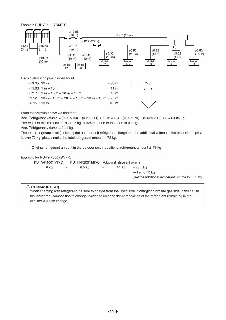
-118-
Example PUHY-P600YSMF-C
ø12.7(3 m)
ø15.88(1 m)
ø19.05(30 m)
ø15.88(10 m)
ø12.7 (20 m)
ø12.7 (10 m)
ø12.7(10 m)
ø9.52(10 m)
ø9.52(10 m)
ø6.35(10 m)
ø9.52(20 m)
ø9.52(10 m) ø9.52
(10 m)
ø9.52(10 m)
Each distribution pipe carries liquid.ø19.05: 30 m = 30 m
ø15.88: 1 m + 10 m mø12.7 : 3 m + 10 m + 20 m + 10 m = 43 mø9.52 : 10 m + 10 m + 20 m + 10 m + 10 m + 10 m = 70 m
ø6.35 : 10 m =10 m
From the formula above we find that:
Add. Refrigerant volume = (0.29 × 30) + (0.25 × 11) + (0.12 × 43) + (0.06 × 70) + (0.024 × 10) + 3 = 24.05 kgThe result of this calculation is 24.05 kg, however round to the nearest 0.1 kg:Add. Refrigerant volume = 24.1 kg.
The total refrigerant level (including the outdoor unit refrigerant charge and the additional volume in the extension pipes)is over 73 kg, please make the total refrigerant amount = 73 kg.
Original refrigerant amount in the outdoor unit + additional refrigerant amount 73 kg
Example for PUHY-P600YSMF-C
PUHY-P400YMF-C PUHN-P200YMF-C Additional refrigerant volume16 kg + 6.5 kg + 51 kg = 73.5 kg
→ Fix to 73 kg
(Set the additional refrigerant volume to 50.5 kg.)
Model80
Model125
Model32
Model125
Model80
Model63
Model71
Caution: (R407C)When charging with refrigerant, be sure to charge from the liquid side. If charging from the gas side, it will causethe refrigerant composition to change inside the unit and the composition of the refrigerant remaining in the
canister will also change.
= 11
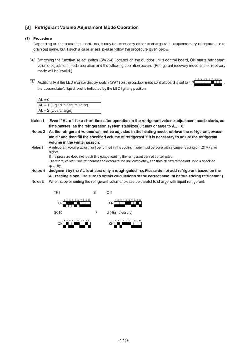
-119-
TH1 S C11
SC16 P d (High pressure)
[3] Refrigerant Volume Adjustment Mode Operation
(1) ProcedureDepending on the operating conditions, it may be necessary either to charge with supplementary refrigerant, or to
drain out some, but if such a case arises, please follow the procedure given below.
Switching the function select switch (SW2-4), located on the outdoor unit’s control board, ON starts refrigerant
volume adjustment mode operation and the following operation occurs. (Refrigerant recovery mode and oil recoverymode will be invalid.)
Additionally, if the LED monitor display switch (SW1) on the outdoor unit’s control board is set to 1 2 3 4 5 6 7 8 9 10
ON ,
the accumulator’s liquid level is indicated by the LED lighting position.
AL = 0AL = 1 (Liquid in accumulator)
AL = 2 (Overcharge)
1
2
Notes 1 Even if AL = 1 for a short time after operation in the refrigerant volume adjustment mode starts, astime passes (as the refrigeration system stabilizes), it may change to AL = 0.
Notes 2 As the refrigerant volume can not be adjusted in the heating mode, retrieve the refrigerant, evacu-ate air and then fill the specified volume of refrigerant if it is necessary to adjust the refrigerantvolume in the winter season.
Notes 3 A refrigerant volume adjustment performed in the cooling mode must be done with a gauge reading of 1.27MPa orhigher.If the pressure does not reach this guage reading the refrigerant cannot be collected.Therefore, collect used refrigerant and evacuate the unit completely, and then fill new refrigerant up to a specifiedquantity.
Notes 4 Judgment by the AL is at best only a rough guideline. Please do not add refrigerant based on theAL reading alone. (Be sure to obtain calculations of the correct amount before adding refrigerant.)
Notes 5 When supplementing the refrigerant volume, please be careful to charge with liquid refrigerant.
1 2 3 4 5 6 7 8 9 10
ON
1 2 3 4 5 6 7 8 9 10
ON
1 2 3 4 5 6 7 8 9 10
ON
1 2 3 4 5 6 7 8 9 10
ON
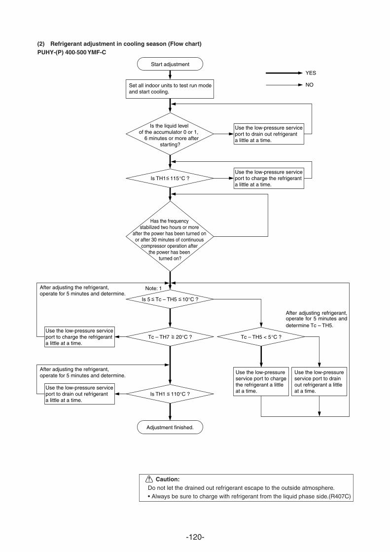
-120-
Caution:Do not let the drained out refrigerant escape to the outside atmosphere.• Always be sure to charge with refrigerant from the liquid phase side.(R407C)
(2) Refrigerant adjustment in cooling season (Flow chart)PUHY-(P) 400·500 YMF-C
Start adjustment
Set all indoor units to test run mode and start cooling.
Is the liquid level of the accumulator 0 or 1,
6 minutes or more after starting?
Use the low-pressure service port to drain out refrigerant a little at a time.
Use the low-pressure service port to charge the refrigerant a little at a time.
Is TH1 115°C ?
After adjusting the refrigerant, operate for 5 minutes and determine.
Note: 1
Tc – TH5 < 5°C ?
Adjustment finished.
Use the low-pressure service port to charge the refrigerant a little at a time.
After adjusting the refrigerant, operate for 5 minutes and determine.
Use the low-pressure service port to drain out refrigerant a little at a time.
Use the low-pressure service port to charge the refrigerant a little at a time.
Use the low-pressure service port to drain out refrigerant a little at a time.
YES
NO
After adjusting refrigerant, operate for 5 minutes and determine Tc – TH5.
Has the frequency stabilized two hours or more
after the power has been turned on or after 30 minutes of continuous
compressor operation after the power has been
turned on?
Is TH1 110°C ?
Is 5 Tc – TH5 10°C ?
Tc – TH7 20°C ?
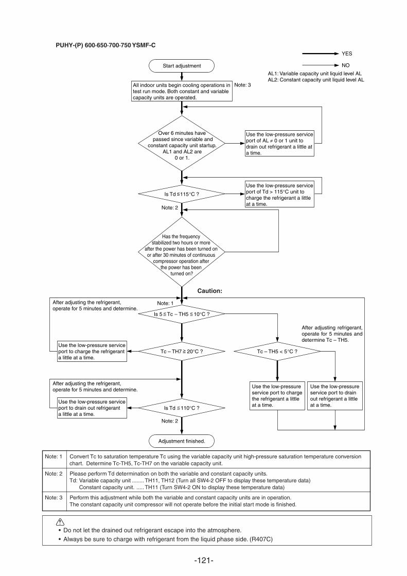
-121-
PUHY-(P) 600·650·700·750 YSMF-C
Over 6 minutes have passed since variable and
constant capacity unit startup.AL1 and AL2 are
0 or 1.
Start adjustment
All indoor units begin cooling operations intest run mode. Both constant and variablecapacity units are operated.
Use the low-pressure service port of AL ≠ 0 or 1 unit todrain out refrigerant a little ata time.
Use the low-pressure service port of Td > 115°C unit tocharge the refrigerant a littleat a time.
Is Td 115°C ?
After adjusting the refrigerant, operate for 5 minutes and determine.
Note: 1
Note: 3
Note: 2
Note: 2
Tc – TH5 < 5°C ?
Adjustment finished.
Use the low-pressure service port to charge the refrigerant a little at a time.
After adjusting the refrigerant, operate for 5 minutes and determine.
Use the low-pressure service port to drain out refrigerant a little at a time.
Use the low-pressure service port to charge the refrigerant a little at a time.
Use the low-pressure service port to drain out refrigerant a little at a time.
YES
NO
After adjusting refrigerant, operate for 5 minutes and determine Tc – TH5.
Has the frequency stabilized two hours or more
after the power has been turned on or after 30 minutes of continuous
compressor operation after the power has been
turned on?
Is Td 110°C ?
Is 5 Tc – TH5 10°C ?
Tc – TH7 20°C ?
AL1: Variable capacity unit liquid level ALAL2: Constant capacity unit liquid level AL
Note: 1 Convert Tc to saturation temperature Tc using the variable capacity unit high-pressure saturation temperature conversionchart. Determine Tc-TH5, Tc-TH7 on the variable capacity unit.
Note: 2 Please perform Td determination on both the variable and constant capacity units.Td: Variable capacity unit ........TH11, TH12 (Turn all SW4-2 OFF to display these temperature data)
Constant capacity unit. ..... TH11 (Turn SW4-2 ON to display these temperature data)
Note: 3 Perform this adjustment while both the variable and constant capacity units are in operation.The constant capacity unit compressor will not operate before the initial start mode is finished.
Caution:
• Do not let the drained out refrigerant escape into the atmosphere.
• Always be sure to charge with refrigerant from the liquid phase side. (R407C)
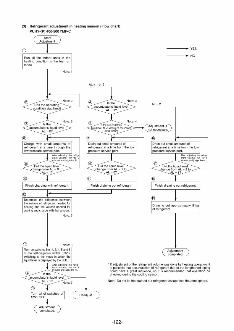
-122-
(3) Refrigerant adjustment in heating season (Flow chart)PUHY-(P) 400·500 YMF-C
StartAdjustment
Has the operating condition stabilized?
Is the accumulator's liquid level
AL = 0?
Did the liquid level change from AL = 0 to
AL = 1?
Did the liquid level change from AL = 1 to
AL = 0?
Did the liquid level change from AL = 2 to
AL = 1?
Is the accumulator's liquid level
AL = 1?
Is the accumulator's liquid level
AL = 1?
Is the accumulator's liquid level AL=0 when just one indoor
unit is running.
Adjustment is not necessary.
Run all the indoor units in the heating condition in the test run mode.
Turn on switches No. 1, 2, 4, 5 and 6 of the self-diagnosis switch (SW1), switching to the mode in which the liquid level is displayed by the LED.
Determine the difference between the volume of refrigerant needed for heating and the volume needed for cooling and charge with that amount.
Charge with small amounts of refrigerant at a time through the low pressure service port.
Drain out small amounts of refrigerant at a time from the low pressure service port.
Drain out small amounts of refrigerant at a time from the low pressure service port.
Draining out approximately 5 kg of refrigerant.
Turn all of switches of SW1 OFF.
Adjustment complated.
Adjustment complated.
Readjust.
YES
NO
Finish charging with refrigerant. Finish draining out refrigerant. Finish draining out refrigerant.
Note: 1
Note: 2
Note: 5
Note: 6
Note: 7
Note: 3
Note: 3
Note: 4
AL = 1 or 2
AL = 2
If adjustment of the refrigerant volume was done by heating operation, it is possible that accumulation of refrigerant due to the lengthened piping could have a great influence, so it is recommended that operation be checked during the cooling season.
*
Note: Do not let the drained out refrigerant escape into the atmosphere.
After adjusting the refrig-erant volume, run for 5 minutes and judge the AL.
After adjusting the refrig-erant volume, run for 5 minutes and judge the AL.
After adjusting the refrig-
minutes and judge the AL.
1
2
3
6
8
10
4
5
7
9
11
16
17
18
1912
13
14
15
erant volume, run for 5
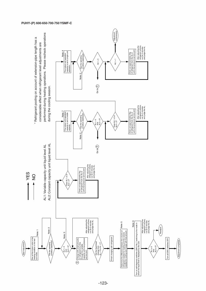
-123-
PUHY-(P) 600·650·700·750 YSMF-C
YE
SN
O
Sta
rt A
djus
tmen
t
Adj
ustm
ent c
ompl
eted
Run
all
the
indo
or u
nits
in th
ehe
atin
g co
nditi
on in
the
test
run
mod
e.
Has
the
oper
atin
gco
nditi
on s
tabi
lized
?
AL1
= 0
And
AL2
= 0
?
Has
the
oper
atin
gco
nditi
on s
tabi
lized
?H
as th
e op
erat
ing
cond
ition
sta
biliz
ed?
AL1
= 0
And
AL2
= 0
?A
L1 =
0
AL1
= 1
AL1
= 2
And
AL2
= 2
?
Cha
rge
with
sm
all a
mou
nts
of r
efrig
eran
t at a
tim
eth
roug
h th
e va
riabl
eca
paci
ty u
nit's
low
pre
ssur
ese
rvic
e po
rt.
Afte
r ad
just
ing
the
refr
iger
ant v
olum
e,ru
n fo
r 5
min
utes
and
judg
e th
e A
L.
Afte
r ad
just
ing
the
refr
iger
ant v
olum
e,ru
n fo
r 5
min
utes
and
judg
e th
e A
L.
Afte
r ad
just
ing
the
refr
iger
ant v
olum
e,ru
n fo
r 5
min
utes
and
judg
e th
e A
L.
Afte
r ad
just
ing
the
refr
iger
ant v
olum
e,ru
n fo
r 5
min
utes
and
judg
e th
e A
L.A
fter
adju
stin
g th
ere
frig
eran
t vol
ume,
run
for
5 m
inut
esan
d ju
dge
the
AL.
Did
the
liqui
d le
vel
chan
ge fr
omA
L =
0 to
AL
=1?
Fin
ish
char
ging
with
ref
riger
ant.
Det
erm
ine
the
diffe
renc
e be
twee
n th
e vo
lum
e of
refr
iger
ant n
eede
d fo
r he
atin
g an
d th
e vo
lum
ene
eded
for
cool
ing
and
char
ge w
ith th
at a
mou
nt.
Turn
on
self-
diag
nosi
s sw
itche
s (S
W1)
No.
7 s
witc
hing
to th
e m
ode
inw
hich
the
liqui
d le
vel i
s di
spla
yed
by th
e LE
D.
Rea
djus
t
Turn
all
SW
1 sw
itche
s O
FF
Doe
s A
L1 =
2 or
AL2
= 2
?
Dra
in o
ut a
ppro
xim
atel
y 5k
gof
ref
riger
ant f
rom
the
AL=
2un
it's
low
-pre
ssur
e se
rvic
e po
rt.
Doe
s A
L1 =
2 or
AL2
= 2
?
Dra
in o
ut a
ppro
xim
atel
y 5k
gof
ref
riger
ant f
rom
the
AL=
2un
it's
low
-pre
ssur
e se
rvic
e po
rt.
Dra
in o
ut a
ppro
xim
atel
y 5k
gof
ref
riger
ant f
rom
the
AL=
2un
it's
low
-pre
ssur
e se
rvic
e po
rt.
The
indo
or u
nit o
pera
tion
capa
city
is s
et to
mid
dle
capa
city
.
The
indo
or u
nit o
pera
tion
capa
city
is s
et to
sin
gle-
unit
oper
atio
n.
Adj
ustm
ent
unne
cess
ary.
Not
e: 1
Not
e: 2
Not
e: 3
Not
e: 5
Not
e: 7
Not
e: 4
Not
e: 2
Not
e: 2
Not
e: 6
1
Go
to
Go
to
AL1
:Var
iabl
e ca
paci
ty u
nit l
iqui
d le
vel A
LA
L2:C
onst
ant c
apac
ity u
nit l
iqui
d le
vel A
L
*R
efrig
eran
t poo
ling
on a
ccou
nt o
f ext
ensi
on-p
ipe
leng
th h
as a
cons
ider
able
effe
ct w
hen
refr
iger
ant l
evel
adj
ustm
ents
are
perf
orm
ed d
urin
g he
atin
g op
erat
ions
. P
leas
e re
chec
k op
erat
ions
durin
g th
e co
olin
g se
ason
. 11
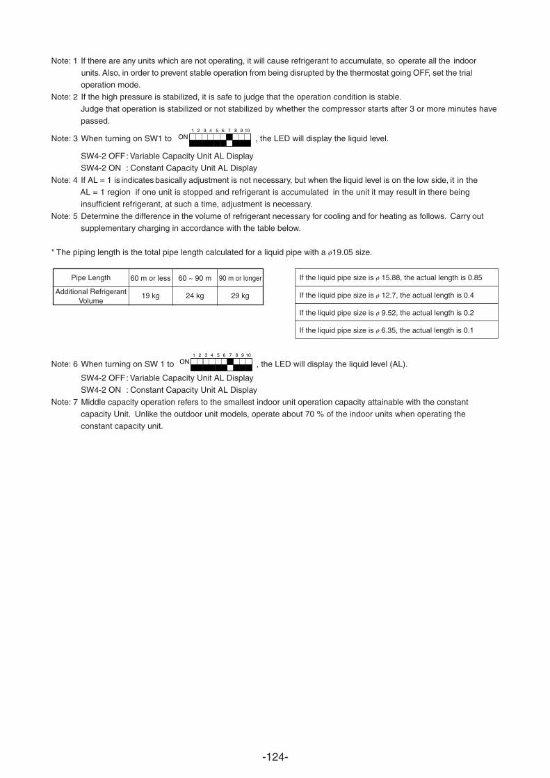
-124-
Note: 1 If there are any units which are not operating, it will cause refrigerant to accumulate, so operate all the indoor units. Also, in order to prevent stable operation from being disrupted by the thermostat going OFF, set the trialoperation mode.
Note: 2 If the high pressure is stabilized, it is safe to judge that the operation condition is stable.Judge that operation is stabilized or not stabilized by whether the compressor starts after 3 or more minutes havepassed.
Note: 3 When turning on SW1 to 1 2 3 4 5 6 7 8 9 10
ON , the LED will display the liquid level.
SW4-2 OFF: Variable Capacity Unit AL DisplaySW4-2 ON : Constant Capacity Unit AL Display
Note: 4 If AL = 1 is indicates basically adjustment is not necessary, but when the liquid level is on the low side, in it the AL = 1 region if one unit is stopped and refrigerant is accumulated in the unit it may result in there beinginsufficient refrigerant, at such a time, adjustment is necessary.
Note: 5 Determine the difference in the volume of refrigerant necessary for cooling and for heating as follows. outsupplementary charging in accordance with the table below.
* The piping length is the total pipe length calculated for a liquid pipe with a ø19.05 size.
Note: 6 When turning on SW 1 to 1 2 3 4 5 6 7 8 9 10
ON , the LED will display the liquid level (AL).
SW4-2 OFF: Variable Capacity Unit AL DisplaySW4-2 ON : Constant Capacity Unit AL Display
Note: 7 Middle capacity operation refers to the smallest indoor unit operation capacity attainable with the constantcapacity Unit. Unlike the outdoor unit models, operate about 70 % of the indoor units when operating theconstant capacity unit.
Pipe Length
Additional RefrigerantVolume
60 m or less 60 ~ 90 m 90 m or longer
19 kg 24 kg 29 kg
If the liquid pipe size is ø 15.88, the actual length is 0.85
If the liquid pipe size is ø 12.7, the actual length is 0.4
If the liquid pipe size is ø 9.52, the actual length is 0.2
If the liquid pipe size is ø 6.35, the actual length is 0.1
Carry
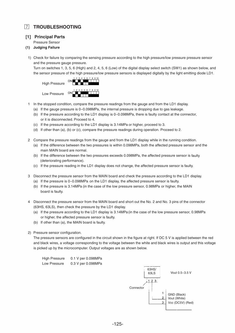
-125-
TROUBLESHOOTING
[1] Principal PartsPressure Sensor
(1) Judging Failure
1) Check for failure by comparing the sensing pressure according to the high pressure/low pressure pressure sensor
and the pressure gauge pressure.Turn on switches 1, 3, 5, 6 (High) and 2, 4, 5, 6 (Low) of the digital display select switch (SW1) as shown below, andthe sensor pressure of the high pressure/low pressure sensors is displayed digitally by the light emitting diode LD1.
High Pressure
Low Pressure
1 In the stopped condition, compare the pressure readings from the gauge and from the LD1 display.
(a) If the gauge pressure is 0~0.098MPa, the internal pressure is dropping due to gas leakage.(b) If the pressure according to the LD1 display is there is faulty contact at the connector,
or it is disconnected. Proceed to 4.
(c) If the pressure according to the LD1 display is 3.14MPa or higher, proceed to 3.(d) If other than (a), (b) or (c), compare the pressure readings during operation. Proceed to 2.
2 Compare the pressure readings from the gauge and from the LD1 display while in the running condition.(a) If the difference between the two pressures is within 0.098MPa, both the affected pressure sensor and the
main MAIN board are normal.
(b) If the difference between the two pressures exceeds 0.098MPa, the affected pressure sensor is faulty (deteriorating performance).
(c) If the pressure reading in the LD1 display does not change, the affected pressure sensor is faulty.
3 Disconnect the pressure sensor from the MAIN board and check the pressure according to the LD1 display.(a) If the pressure is 0~0.098MPa on the LD1 display, the affected pressure sensor is faulty.(b) If the pressure is (in the case of the low pressure sensor, or higher, the MAIN
board is faulty.
4 Disconnect the pressure sensor from the MAIN board and short out the No. 2 and No. 3 pins of the connector
(63HS, 63LS), then check the pressure by the LD1 display.(a) If the pressure according to the LD1 display is (in the case of the low pressure sensor,
or higher, the affected pressure sensor is faulty.
(b) If other than (a), the MAIN board is faulty.
2) Pressure sensor configuration.
The pressure sensors are configured in the circuit shown in the figure at right. If DC 5 V is applied between the redand black wires, a voltage corresponding to the voltage between the white and black wires is output and this voltageis picked up by the microcomputer. Output voltages are as shown below.
High Pressure 0.1 V per Low Pressure 0.3 V per
1 2 3 4 5 6 7 8 9 10
ON
1 2 3 4 5 6 7 8 9 10
ON
Connector
Vout 0.5~3.5 V
GND (Black)Vout (White)Vcc (DC5V) (Red)
63HS/63LS
0~0.098MPa,
3.14MPa 0.98MPa
3.14MPa 0.98MPa
0.098MPa0.098MPa
¶
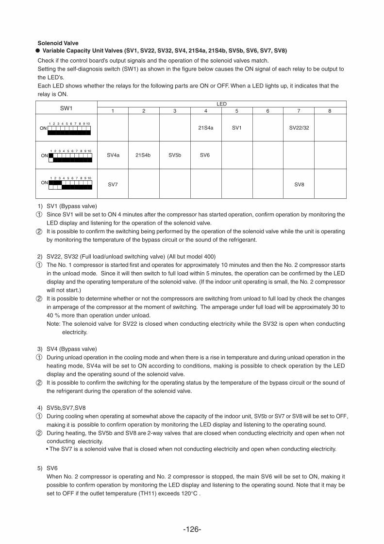
-126-
Solenoid Valve
Check if the control board’s output signals and the operation of the solenoid valves match.Setting the self-diagnosis switch (SW1) as shown in the figure below causes the ON signal of each relay to be output to
the LED’s.Each LED shows whether the relays for the following parts are ON or OFF. When a LED lights up, it indicates that therelay is ON.
SW1LED
1 2 3 4 5 6 7 8 9 10
ON
1 2 3 4 5 6 7 8 9 10
ON SV6SV4a
SV22/32SV1
1) SV1 (Bypass valve)1 Since SV1 will be set to ON 4 minutes after the compressor has started operation, confirm operation by monitoring the
LED display and listening for the operation of the solenoid valve.2 It is possible to confirm the switching being performed by the operation of the solenoid valve while the unit is operating
by monitoring the temperature of the bypass circuit or the sound of the refrigerant.
2) SV22, SV32 (Full load/unload switching valve) (All but model 400)1 The No. 1 compressor is started first and operates for approximately 10 minutes and then the No. 2 compressor starts
in the unload mode. Since it will then switch to full load within 5 minutes, the operation can be confirmed by the LEDdisplay and the operating temperature of the solenoid valve. (If the indoor unit operating is small, the No. 2 compressorwill not start.)
2 It is possible to determine whether or not the compressors are switching from unload to full load by check the changes
in amperage of the compressor at the moment of switching. The amperage under full load will be approximately 30 to40 % more than operation under unload.Note: The solenoid valve for SV22 is closed when conducting electricity while the SV32 is open when conducting
electricity.
3) SV4 (Bypass valve)
1 During unload operation in the cooling mode and when there is a rise in temperature and during unload operation in theheating mode, SV4a will be set to ON according to conditions, making is possible to check operation by the LEDdisplay and the operating sound of the solenoid valve.
2 It is possible to confirm the switching for the operating status by the temperature of the bypass circuit or the sound ofthe refrigerant during the operation of the solenoid valve.
5) SV6When No. 2 compressor is operating and No. 2 compressor is stopped, the main SV6 will be set to ON, making itpossible to confirm operation by monitoring the LED display and listening to the operating sound. Note that it may be
set to OFF if the outlet temperature (TH11) exceeds 120°C .
1 2 3 4 5 6 7 8
1 2 3 4 5 6 7 8 9 10
ON SV7
21S4b SV5b
Variable Capacity Unit Valves (SV1, SV22, SV32, SV4, 21S4a, 21S4b, SV5b, SV6, SV7, SV8)
4) SV5b,SV7,SV81 During cooling when operating at somewhat above the capacity of the indoor unit, SV5b or SV7 or SV8 will be set to OFF,
making it is possible to confirm operation by monitoring the LED display and listening to the operating sound.
2 During heating, the SV5b and SV8 2-way valves that are closed when conducting electricity and open when not are conducting electricity.
SV8
21S4a
• The SV7 is a solenoid valve that is closed when not conducting electricity and open when conducting electricity.
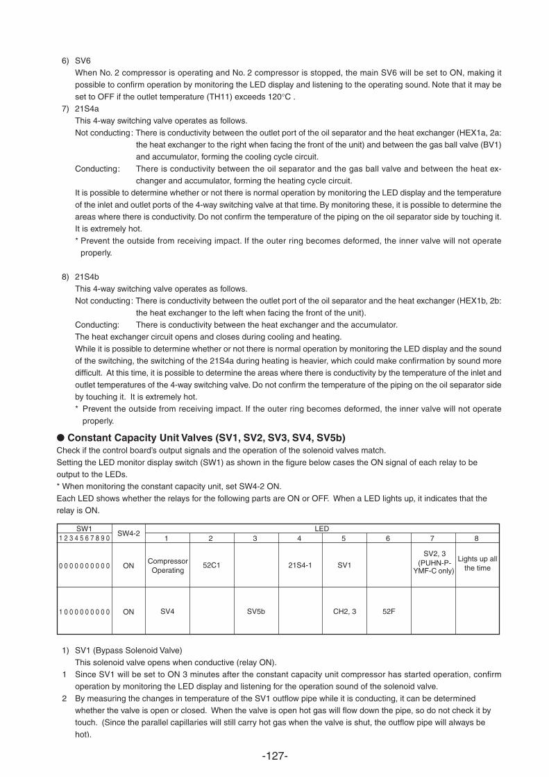
-127-
6) SV6When No. 2 compressor is operating and No. 2 compressor is stopped, the main SV6 will be set to ON, making itpossible to confirm operation by monitoring the LED display and listening to the operating sound. Note that it may be
set to OFF if the outlet temperature (TH11) exceeds 120°C .7) 21S4a
This 4-way switching valve operates as follows.
Not conducting: There is conductivity between the outlet port of the oil separator and the heat exchanger (HEX1a, 2a:the heat exchanger to the right when facing the front of the unit) and between the gas ball valve (BV1)and accumulator, forming the cooling cycle circuit.
Conducting: There is conductivity between the oil separator and the gas ball valve and between the heat ex-changer and accumulator, forming the heating cycle circuit.
It is possible to determine whether or not there is normal operation by monitoring the LED display and the temperature
of the inlet and outlet ports of the 4-way switching valve at that time. By monitoring these, it is possible to determine theareas where there is conductivity. Do not confirm the temperature of the piping on the oil separator side by touching it.It is extremely hot.
* Prevent the outside from receiving impact. If the outer ring becomes deformed, the inner valve will not operateproperly.
8) 21S4bThis 4-way switching valve operates as follows.Not conducting: There is conductivity between the outlet port of the oil separator and the heat exchanger (HEX1b, 2b:
the heat exchanger to the left when facing the front of the unit).Conducting: There is conductivity between the heat exchanger and the accumulator.The heat exchanger circuit opens and closes during cooling and heating.
While it is possible to determine whether or not there is normal operation by monitoring the LED display and the soundof the switching, the switching of the 21S4a during heating is heavier, which could make confirmation by sound moredifficult. At this time, it is possible to determine the areas where there is conductivity by the temperature of the inlet and
outlet temperatures of the 4-way switching valve. Do not confirm the temperature of the piping on the oil separator sideby touching it. It is extremely hot.* Prevent the outside from receiving impact. If the outer ring becomes deformed, the inner valve will not operate
properly.
Constant Capacity Unit Valves (SV1, SV2, SV3, SV4, SV5b)Check if the control board’s output signals and the operation of the solenoid valves match.
Setting the LED monitor display switch (SW1) as shown in the figure below cases the ON signal of each relay to be
* When monitoring the constant capacity unit, set SW4-2 ON.
Each LED shows whether the relays for the following parts are ON or OFF. When a LED lights up, it indicates that therelay is ON.
SW11 2 3 4 5 6 7 8 9 0
0 0 0 0 0 0 0 0 0 0
1 0 0 0 0 0 0 0 0 0
LED1 2 3 4 5 6 7 8
CompressorOperating
Lights up allthe time
SV4 SV5b CH2, 3 52F
SW4-2
ON
ON
52C1 21S4-1 SV1
1) SV1 (Bypass Solenoid Valve)
This solenoid valve opens when conductive (relay ON).1 Since SV1 will be set to ON 3 minutes after the constant capacity unit compressor has started operation, confirm
operation by monitoring the LED display and listening for the operation sound of the solenoid valve.
2 By measuring the changes in temperature of the SV1 outflow pipe while it is conducting, it can be determinedwhether the valve is open or closed. When the valve is open hot gas will flow down the pipe, so do not check it bytouch. (Since the parallel capillaries will still carry hot gas when the valve is shut, the outflow pipe will always be
hot).
SV2, 3(PUHN-P-
YMF-C only)
output to the LEDs.
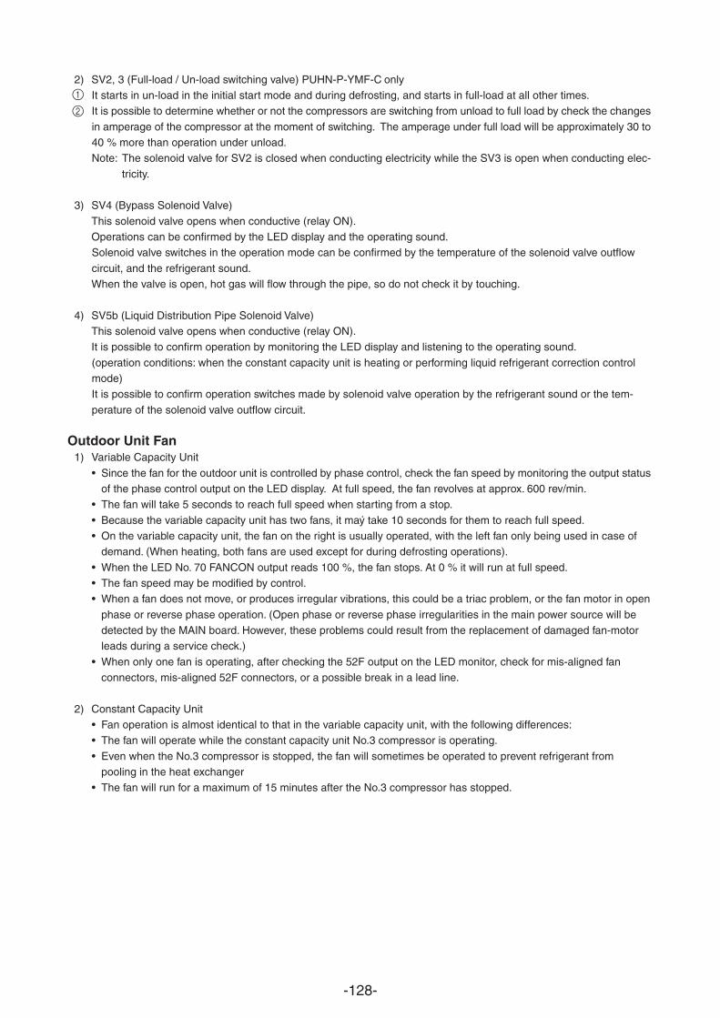
-128-
2) SV2, 3 (Full-load / Un-load switching valve) PUHN-P-YMF-C onlyIt starts in un-load in the initial start mode and during defrosting, and starts in full-load at all other times.It is possible to determine whether or not the compressors are switching from unload to full load by check the changes
in amperage of the compressor at the moment of switching. The amperage under full load will be approximately 30 to40 % more than operation under unload.Note: The solenoid valve for SV2 is closed when conducting electricity while the SV3 is open when conducting elec-
tricity.
3) SV4 (Bypass Solenoid Valve)
This solenoid valve opens when conductive (relay ON).Operations can be confirmed by the LED display and the operating sound.Solenoid valve switches in the operation mode can be confirmed by the temperature of the solenoid valve outflow
circuit, and the refrigerant sound.When the valve is open, hot gas will flow through the pipe, so do not check it by touching.
4) SV5b (Liquid Distribution Pipe Solenoid Valve)This solenoid valve opens when conductive (relay ON).It is possible to confirm operation by monitoring the LED display and listening to the operating sound.
(operation conditions: when the constant capacity unit is heating or performing liquid refrigerant correction controlmode)It is possible to confirm operation switches made by solenoid valve operation by the refrigerant sound or the tem-
perature of the solenoid valve outflow circuit.
Outdoor Unit Fan1) Variable Capacity Unit
• Since the fan for the outdoor unit is controlled by phase control, check the fan speed by monitoring the output statusof the phase control output on the LED display. At full speed, the fan revolves at approx. 600 rev/min.
• The fan will take 5 seconds to reach full speed when starting from a stop.
• Because the variable capacity unit has two fans, it may take 10 seconds for them to reach full speed.• On the variable capacity unit, the fan on the right is usually operated, with the left fan only being used in case of
demand. (When heating, both fans are used except for during defrosting operations).
• When the LED No. 70 FANCON output reads 100 %, the fan stops. At 0 % it will run at full speed.• The fan speed may be modified by control.• When a fan does not move, or produces irregular vibrations, this could be a triac problem, or the fan motor in open
phase or reverse phase operation. (Open phase or reverse phase irregularities in the main power source will bedetected by the MAIN board. However, these problems could result from the replacement of damaged fan-motorleads during a service check.)
• When only one fan is operating, after checking the 52F output on the LED monitor, check for mis-aligned fanconnectors, mis-aligned 52F connectors, or a possible break in a lead line.
2) Constant Capacity Unit• Fan operation is almost identical to that in the variable capacity unit, with the following differences:• The fan will operate while the constant capacity unit No.3 compressor is operating.
• Even when the No.3 compressor is stopped, the fan will sometimes be operated to prevent refrigerant frompooling in the heat exchanger
.
• The fan will run for a maximum of 15 minutes after the No.3 compressor has stopped.
1
2
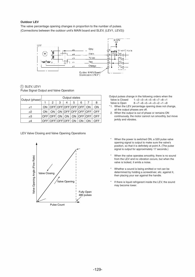
-129-
Outdoor LEVThe valve percentage opening changes in proportion to the number of pulses.(Connections between the outdoor unit’s MAIN board and SLEV, (LEV1, LEV2))
Output (phase)Output states Output pulses change in the following orders when the
Valve is Closed 1→2→3→4→5→6→7→8→1Valve is Open 8→7→6→5→4→3→2→1→8
*1. When the LEV percentage opening does not change,all the output phases are off.
2. When the output is out of phase or remains ONcontinuously, the motor cannot run smoothly, but movejerkily and vibrates.
* When the power is switched ON, a 520 pulse valveopening signal is output to make sure the valve’sposition, so that it is definitely at point A. (The pulsesignal is output for approximately 17 seconds.)
* When the valve operates smoothly, there is no soundfrom the LEV and no vibration occurs, but when thevalve is locked, it emits a noise.
* Whether a sound is being emitted or not can bedetermined by holding a screwdriver, etc. against it,then placing your ear against the handle.
* If there is liquid refrigerant inside the LEV, the soundmay become lower.
Val
ve O
peni
ng A
ngle
(F
low
Rat
e)
Pulse Count
Valve Opening
Fully Open480 pulses
Valve Closing
Pulse Signal Output and Valve Operation
1 2 3 4 5 6 7 8
ø1 ON OFF OFF OFF OFF OFF ON ON
ø2 ON ON ON OFF OFF OFF OFF OFF
ø3 OFF OFF ON ON ON OFF OFF OFF
ø4 OFF OFF OFF OFF ON ON ON OFF
LEV Valve Closing and Valve Opening Operations
1 SLEV, LEV1
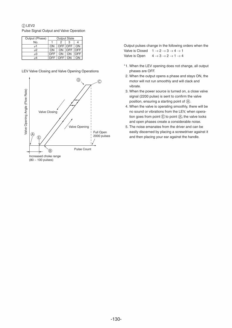
-130-
2 LEV2Pulse Signal Output and Valve Operation
Output (Phase) Output StateNo. 1 2 3 4ø1 ON OFF OFF ONø2 ON ON OFF OFFø3 OFF ON ON OFFø4 OFF OFF ON ON
LEV Valve Closing and Valve Opening Operations
Val
ve O
peni
ng A
ngle
(F
low
Rat
e)
Increased choke range(80 ~ 100 pulses)
Pulse Count
Full Open2000 pulses
Valve Closing
Valve Opening
C
A
B
Output pulses change in the following orders when the
Valve is Closed 1 → 2 → 3 → 4 → 1Valve is Open 4 → 3 → 2 → 1 → 4
*1. When the LEV opening does not change, all outputphases are OFF.
2. When the output opens a phase and stays ON, the
motor will not run smoothly and will clack andvibrate.
3. When the power source is turned on, a close valve
signal (2200 pulse) is sent to confirm the valveposition, ensuring a starting point of A.
4. When the valve is operating smoothly, there will be
no sound or vibrations from the LEV, when opera-tion goes from point E to point A, the valve locksand open phases create a considerable noise.
5. The noise emanates from the driver and can beeasily discerned by placing a screwdriver against itand then placing your ear against the handle.
D
E
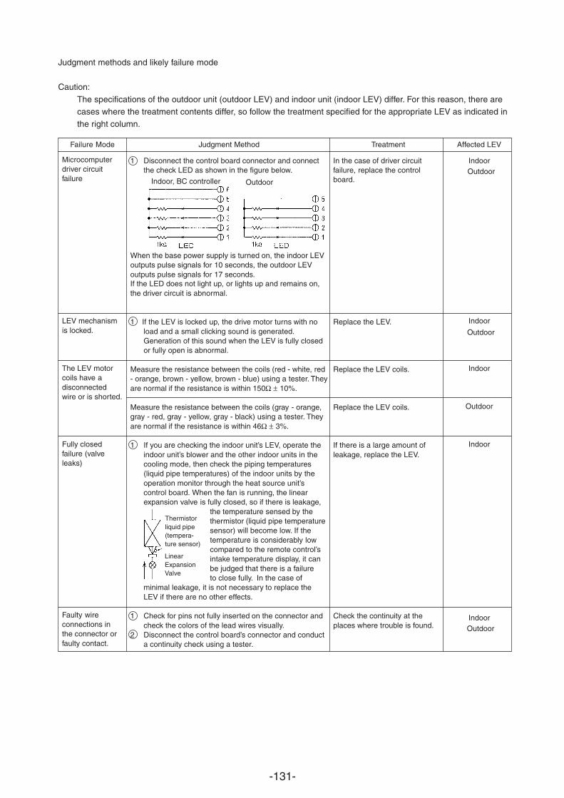
-131-
1 Disconnect the control board connector and connectthe check LED as shown in the figure below.
When the base power supply is turned on, the indoor LEVoutputs pulse signals for 10 seconds, the outdoor LEVoutputs pulse signals for 17 seconds. If the LED does not light up, or lights up and remains on,the driver circuit is abnormal.
1 If the LEV is locked up, the drive motor turns with noload and a small clicking sound is generated.Generation of this sound when the LEV is fully closedor fully open is abnormal.
Measure the resistance between the coils (red - white, red- orange, brown - yellow, brown - blue) using a tester. Theyare normal if the resistance is within 150Ω ± 10%.
Measure the resistance between the coils (gray - orange,gray - red, gray - yellow, gray - black) using a tester. Theyare normal if the resistance is within 46Ω ± 3%.
1 If you are checking the indoor unit’s LEV, operate theindoor unit’s blower and the other indoor units in thecooling mode, then check the piping temperatures(liquid pipe temperatures) of the indoor units by theoperation monitor through the heat source unit’scontrol board. When the fan is running, the linearexpansion valve is fully closed, so if there is leakage,
the temperature sensed by thethermistor (liquid pipe temperaturesensor) will become low. If thetemperature is considerably lowcompared to the remote control’sintake temperature display, it canbe judged that there is a failureto close fully. In the case of
minimal leakage, it is not necessary to replace theLEV if there are no other effects.
1 Check for pins not fully inserted on the connector andcheck the colors of the lead wires visually.
2 Disconnect the control board’s connector and conducta continuity check using a tester.
Judgment methods and likely failure mode
Caution:
The specifications of the outdoor unit (outdoor LEV) and indoor unit (indoor LEV) differ. For this reason, there arecases where the treatment contents differ, so follow the treatment specified for the appropriate LEV as indicated inthe right column.
Microcomputerdriver circuitfailure
LEV mechanismis locked.
The LEV motorcoils have adisconnectedwire or is shorted.
Fully closedfailure (valveleaks)
Faulty wireconnections inthe connector orfaulty contact.
Failure Mode Judgment Method Treatment Affected LEV
Thermistorliquid pipe(tempera-ture sensor)
LinearExpansionValve
In the case of driver circuitfailure, replace the controlboard.
Replace the LEV.
Replace the LEV coils.
Replace the LEV coils.
If there is a large amount ofleakage, replace the LEV.
Check the continuity at theplaces where trouble is found.
IndoorOutdoor
Indoor
Outdoor
Indoor
Outdoor
Indoor
IndoorOutdoor
OutdoorIndoor, BC controller
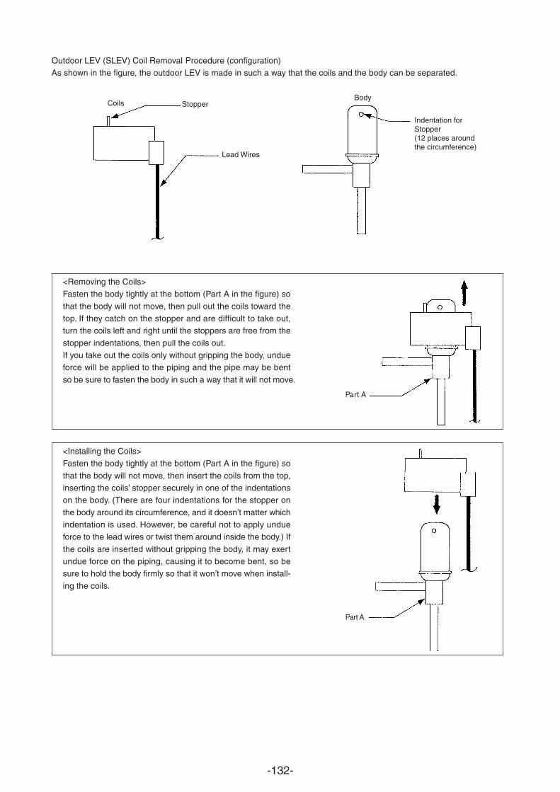
-132-
Outdoor LEV (SLEV) Coil Removal Procedure (configuration)As shown in the figure, the outdoor LEV is made in such a way that the coils and the body can be separated.
<Removing the Coils>Fasten the body tightly at the bottom (Part A in the figure) so
that the body will not move, then pull out the coils toward thetop. If they catch on the stopper and are difficult to take out,turn the coils left and right until the stoppers are free from the
stopper indentations, then pull the coils out.If you take out the coils only without gripping the body, undueforce will be applied to the piping and the pipe may be bent
so be sure to fasten the body in such a way that it will not move.
<Installing the Coils>Fasten the body tightly at the bottom (Part A in the figure) so
that the body will not move, then insert the coils from the top,inserting the coils’ stopper securely in one of the indentationson the body. (There are four indentations for the stopper on
the body around its circumference, and it doesn’t matter whichindentation is used. However, be careful not to apply undueforce to the lead wires or twist them around inside the body.) If
the coils are inserted without gripping the body, it may exertundue force on the piping, causing it to become bent, so besure to hold the body firmly so that it won’t move when install-
ing the coils.
Coils Stopper
Lead Wires
Body
Indentation forStopper(12 places aroundthe circumference)
Part A
Part A
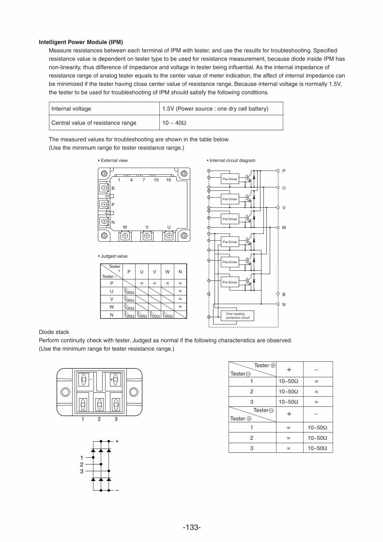
-133-
Intelligent Power Module (IPM)Measure resistances between each terminal of IPM with tester, and use the results for troubleshooting. Specifiedresistance value is dependent on tester type to be used for resistance measurement, because diode inside IPM has
non-linearity, thus difference of impedance and voltage in tester being influential. As the internal impedance ofresistance range of analog tester equals to the center value of meter indication, the affect of internal impedance canbe minimized if the tester having close center value of resistance range. Because internal voltage is normally 1.5V,
the tester to be used for troubleshooting of IPM should satisfy the following conditions.
Internal voltage 1.5V (Power source : one dry cell battery)
Central value of resistance range 10 ~ 40
The measured values for troubleshooting are shown in the table below.(Use the minimum range for tester resistance range.)
Diode stackPerform continuity check with tester. Judged as normal if the following characteristics are observed.(Use the minimum range for tester resistance range.)
1 10~50
2 10~50
3 10~50
1 10~50
2 10~50
3 10~50
1 2 3
123
+
–
Tester
Tester + –
Tester
Tester + –
W
P
• External view • Internal circuit diagram
• Judged value
P
Tester –
Tester+
U 2~1002~1002~1002~100
2~100
2~100
2~100
V
W
N
U V W N
N
P
B
1 4 7 10 16
V
V
U
P
W
N
B
U
3
2
16
5
49
8
7
11
13
10
14
15
12
16
Pre-Driver
Pre-Driver
Pre-Driver
Pre-Driver
Pre-Driver
Pre-Driver
Over heatingprotection circuit
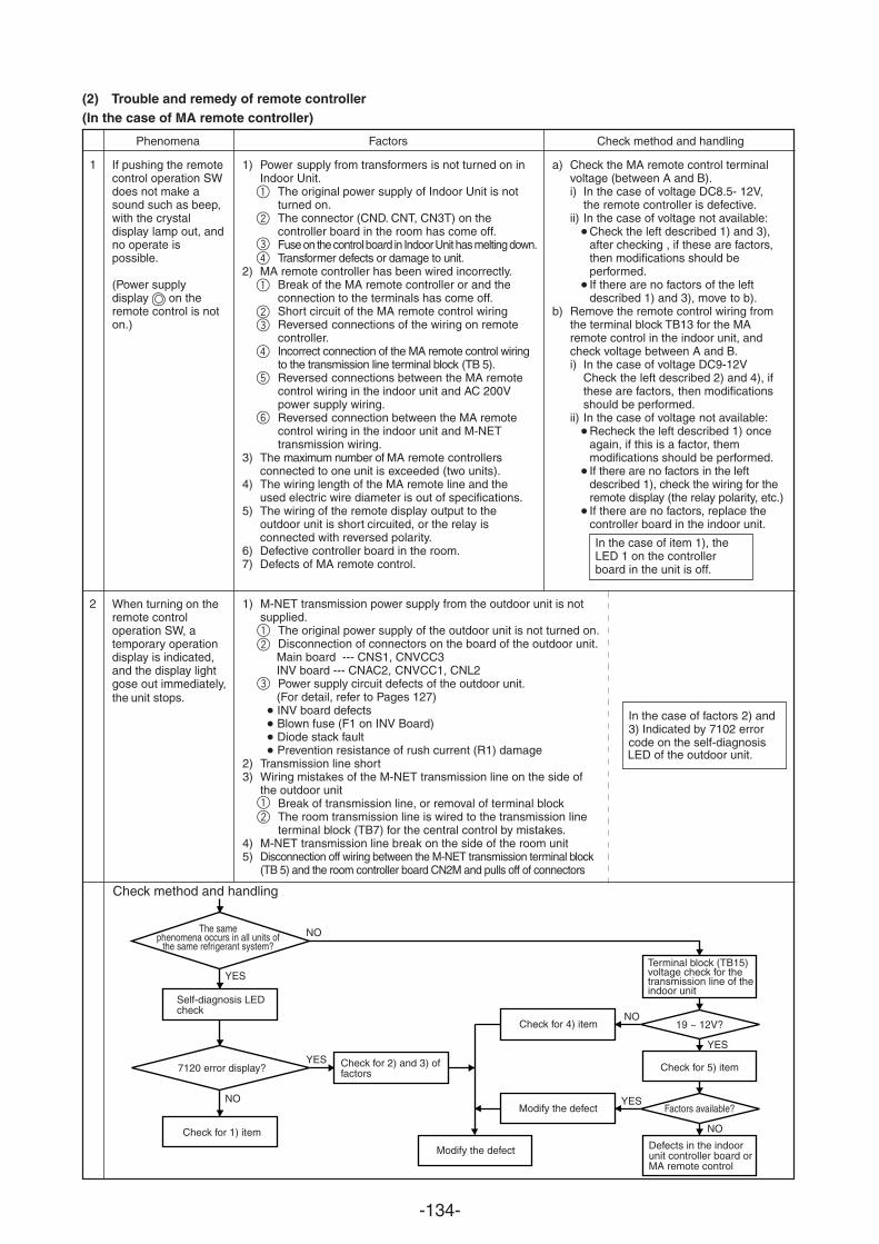
-134-
(2) Trouble and remedy of remote controller(In the case of MA remote controller)
Phenomena Factors Check method and handling
1
2
If pushing the remotecontrol operation SWdoes not make asound such as beep,with the crystaldisplay lamp out, andno operate ispossible.
(Power supplydisplay on theremote control is noton.)
When turning on theremote controloperation SW, atemporary operationdisplay is indicated,and the display light
the unit stops.gose out immediately,
1) Power supply from transformers is not turned on inIndoor Unit.
The original power supply of Indoor Unit is notturned on.The connector (CND. CNT, CN3T) on thecontroller board in the room has come off.Fuse on the control board in Indoor Unit has melting down.Transformer defects or damage to unit.
2) MA remote controller has been wired incorrectly.Break of the MA remote controller or and theconnection to the terminals has come off.Short circuit of the MA remote control wiringReversed connections of the wiring on remotecontroller.Incorrect connection of the MA remote control wiringto the transmission line terminal block (TB 5).Reversed connections between the MA remotecontrol wiring in the indoor unit and AC 200Vpower supply wiring.Reversed connection between the MA remotecontrol wiring in the indoor unit and M-NETtransmission wiring.
3) The maximum number of MA remote controllersconnected to one exceeded (two units).
4) The wiring length of the MA remote line and theused electric wire diameter is out of specifications.
5) The wiring of the remote display output to theoutdoor unit is short circuited, or the relay isconnected with reversed polarity.
6) Defective controller board in the room.7) Defects of MA remote control.
1) M-NET transmission power supply from the outdoor unit is notsupplied.
The original power supply of the outdoor unit is not turned on.Disconnection of connectors on the board of the outdoor unit.Main board --- CNS1, CNVCC3INV board --- CNAC2, CNVCC1, CNL2Power supply circuit defects of the outdoor unit.(For detail, refer to Pages 127)INV board defectsBlown fuse (F1 on INV Board)Diode stack faultPrevention resistance of rush current (R1) damage
2) Transmission line short3) Wiring mistakes of the M-NET transmission line on the side of
the outdoor unit12
Break of transmission line, or removal of terminal blockThe room transmission line is wired to the transmission lineterminal block (TB7) for the central control by mistakes.
4) M-NET transmission line break on the side of the room unit5) Disconnection off wiring between the M-NET transmission terminal block
(TB 5) and the room controller board CN2M and pulls off of connectors
a) Check the MA remote control terminalvoltage (between A and B).i) In the case of voltage DC8.5- 12V,
the remote controller is defective.ii) In the case of voltage not available:
Check the left described 1) and 3),after checking , if these are factors,then modifications should beperformed.If there are no factors of the leftdescribed 1) and 3), move to b).
b) Remove the remote control wiring fromthe terminal block TB13 for the MAremote control in the indoor unit, andcheck voltage between A and B.i) In the case of voltage DC9-12V
Check the left described 2) and 4), ifthese are factors, then modificationsshould be performed.
ii) In the case of voltage not available:Recheck the left described 1) onceagain, if this is a factor, themmodifications should be performed.If there are no factors in the leftdescribed 1), check the wiring for theremote display (the relay polarity, etc.)If there are no factors, replace thecontroller board in the indoor unit.
In the case of item 1), theLED 1 on the controllerboard in the unit is off.
In the case of factors 2) and3) Indicated by 7102 errorcode on the self-diagnosisLED of the outdoor unit.
NO
NO
YES
YES
NO
YES
YES Check for 2) and 3) offactors
Modify the defect
7120 error display?
Check for 1) item
Check for 4) item 19 ~ 12V?
Check for 5) item
Defects in the indoor unit controller board or MA remote control
Factors available?Modify the defect
Terminal block (TB15)voltage check for thetransmission line of theindoor unit
NO
The samephenomena occurs in all units of
the same refrigerant system?
Self-diagnosis LEDcheck
Check method and handling
unit is
12
3
1
2
43
1
23
4
5
6
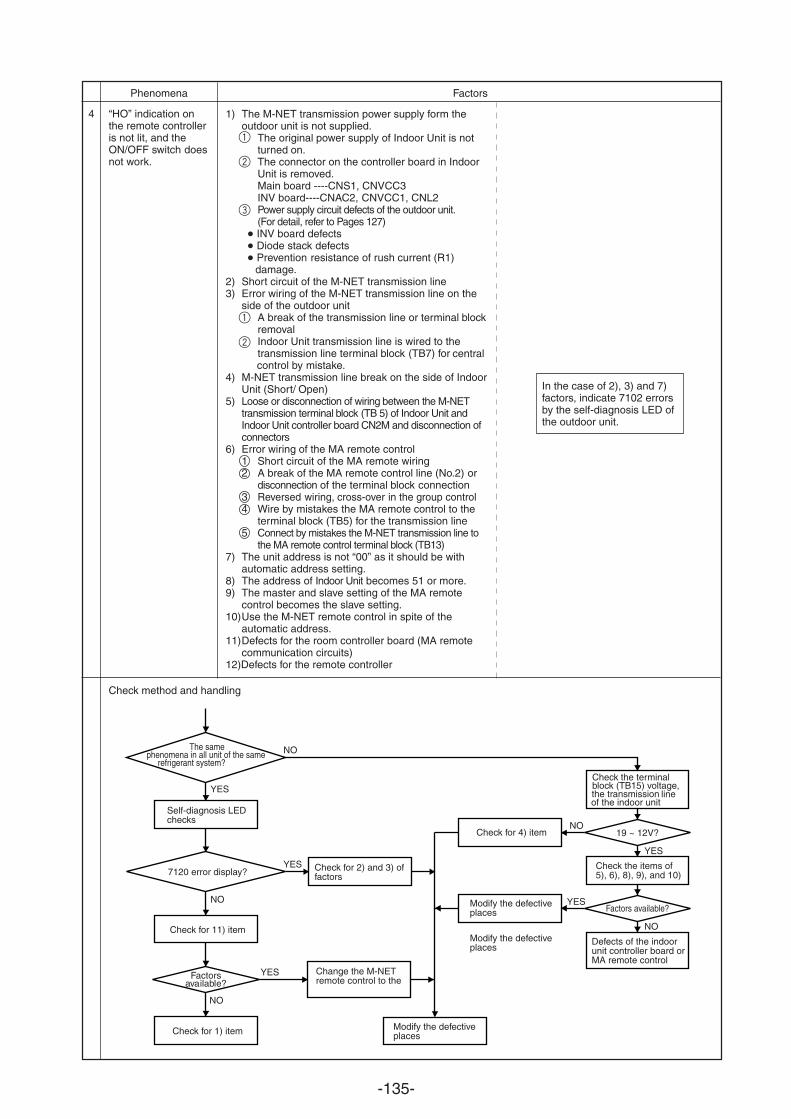
-135-
4 “HO” indication onthe remote controlleris not lit, and theON/OFF switch doesnot work.
1) The M-NET transmission power supply form theoutdoor unit is not supplied.
The original power supply of Indoor Unit is notturned on.The connector on the controller board in IndoorUnit is removed.Main board ----CNS1, CNVCC3INV board----CNAC2, CNVCC1, CNL2Power supply circuit defects of the outdoor unit.(For detail, refer to Pages 127)
INV board defects Diode stack defects Prevention resistance of rush current (R1)
damage.2) Short circuit of the M-NET transmission line3) Error wiring of the M-NET transmission line on the
side of the outdoor unitA break of the transmission line or terminal blockremovalIndoor Unit transmission line is wired to thetransmission line terminal block (TB7) for central control by mistake.
4) M-NET transmission line break on the side of IndoorUnit (Short/ Open)
5) Loose or disconnection of wiring between the M-NETtransmission terminal block (TB 5) of Indoor Unit andIndoor Unit controller board CN2M and disconnection ofconnectors
6) Error wiring of the MA remote control1 Short circuit of the MA remote wiring2 A break of the MA remote control line (No.2) or
disconnection of the terminal block connection3 Reversed wiring, cross-over in the group control4 Wire by mistakes the MA remote control to the
terminal block (TB5) for the transmission line5 Connect by mistakes the M-NET transmission line to
the MA remote control terminal block (TB13)7) The unit address is not “00” as it should be with
automatic address setting.8) The address of Indoor Unit becomes 51 or more.9) The master and slave setting of the MA remote
control becomes the slave setting.10)Use the M-NET remote control in spite of the
automatic address.11)Defects for the room controller board (MA remote
communication circuits)12)Defects for the remote controller
Check method and handling
Phenomena Factors
In the case of 2), 3) and 7)factors, indicate 7102 errorsby the self-diagnosis LED ofthe outdoor unit.
NO
NO
YES
YES
NO
YES
YES Check for 2) and 3) offactors
Modify the defectiveplaces
7120 error display?
Check for 11) item
Check for 4) item 19 ~ 12V?
Check the items of5), 6), 8), 9), and 10)
Defects of the indoor unit controller board or MA remote control
Factors available?Modify the defectiveplaces
Modify the defectiveplaces
Check the terminalblock (TB15) voltage,the transmission line of the indoor unit
NO
The samephenomena in all unit of the same
refrigerant system?
Self-diagnosis LEDchecks
YES
NO
Factorsavailable?
Check for 1) item
Change the M-NETremote control to the
1
3
2
1
2
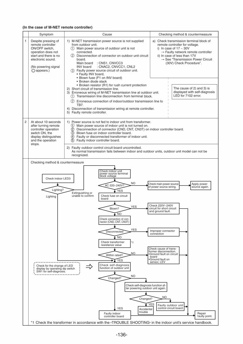
-136-
(In the case of M-NET remote controller)
Symptom Cause Checking method & countermeasure
1
2
Despite pressing ofremote controllerON/OFF switch,operation does notstart and there is noelectronic sound.
(No powering signal appears.)
At about 10 secondsafter turning remotecontroller operationswitch ON, thedisplay distinguishesand the operationstops.
1) M-NET transmission power source is not suppliedfrom outdoor unit.
Main power source of outdoor unit is notconnected.Disconnection of connector on outdoor unit circuitboard.Main board : CNS1, CNVCC3INV board : CNAC2, CNVCC1, CNL2Faulty power source circuit of outdoor unit.• Faulty INV board,• Blown fuse (F1 on INV board)• Broken diode stack• Broken resistor (R1) for rush current protection
2) Short circuit of transmission line.3) Erroneous wiring of M-NET transmission line at outdoor unit.
Transmission line disconnection from terminal block.
Erroneous connection of indoor/outdoor transmission line toTB7.
4) Disconnection of transmission wiring at remote controller.5) Faulty remote controller.
The cause of 2) and 3) isdisplayed with self-diagnosisLED for 7102 error.
1) Power source is not fed to indoor unit from transformer.1 Main power source of indoor unit is not turned on.2 Disconnection of connector (CND, CNT, CN3T) on indoor controller board.34 Faulty or disconnected transformer of indoor unit.5 Faulty indoor controller board.
2) Faulty outdoor control circuit board uncontrolled.As normal transmission fails between indoor and outdoor units, outdoor unit model can not berecognized.
Checking method & countermeasure
a) Check transmission terminal block ofremote controller for voltage.i) In case of 17 ~ 30V
Faulty network remote controllerii) In case of less than 17V
See “Transmission Power Circuit(30V) Check Procedure”.
Check indoor LED3
Lighting?
Check for the change of LEDdisplay by operating dip switchSW1 for self-diagnosis.
Extinguishing orunable to confirm
Check indoor unitpower source terminalblock voltage
AC 220~240V?
Check fuse on circuitboard
Blown?
Check connection of con-nector (CND, CNT, CN3T)
Disconnected
Check transformerresistance value
Within rated?
Check self-diagnosisfunction of outdoor unit
Changed?
Faulty indoorcontroller board
Check main power sourceof power source wiring.
Apply powersource again.
Check 220V~240Vcircuit for short circuitand ground fault.
Improper connectorconnection
Check cause of trans-former disconnection.•Ground fault on circuitboard
•Ground fault onsensor, LEV
Check self-diagnosis function af-ter powering outdoor unit again.
Changed?
Accidentaltrouble
Faulty outdoor unitcontrol circuit board
Repairf
NO
YESYES
NO
NO
YES
YES
NO
NO
YES
YES
Lighting
*1 Check the transformer in accordance with the “TROUBLE SHOOTING” in the indoor unit’s service handbook.
NO
*1
Blown fuse on indoor controller board.
aulty point.
1
2
3
1
2
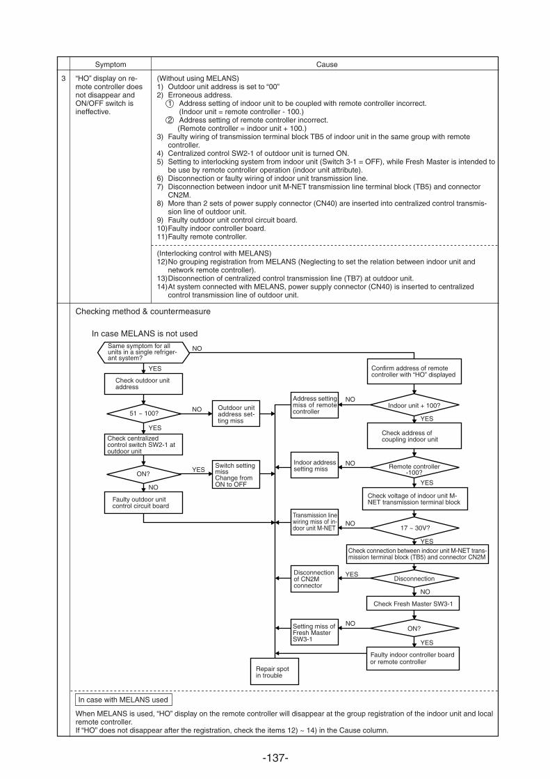
-137-
Symptom Cause
3 “HO” display on re-mote controller doesnot disappear andON/OFF switch isineffective.
(Without using MELANS)1) Outdoor unit address is set to “00”2) Erroneous address.
1 Address setting of indoor unit to be coupled with remote controller incorrect.(Indoor unit = remote controller - 100.)
2 Address setting of remote controller incorrect.(Remote controller = indoor unit + 100.)
3) Faulty wiring of transmission terminal block TB5 of indoor unit in the same group with remotecontroller.
4) Centralized control SW2-1 of outdoor unit is turned ON.5) Setting to interlocking system from indoor unit (Switch 3-1 = OFF), while Fresh Master is intended to
be use by remote controller operation (indoor unit attribute).6) Disconnection or faulty wiring of indoor unit transmission line.7) Disconnection between indoor unit M-NET transmission line terminal block (TB5) and connector
CN2M.8) More than 2 sets of power supply connector (CN40) are inserted into centralized control transmis-
sion line of outdoor unit.9) Faulty outdoor unit control circuit board.10)Faulty indoor controller board.11)Faulty remote controller.
(Interlocking control with MELANS)12)No grouping registration from MELANS (Neglecting to set the relation between indoor unit and
network remote controller).13)Disconnection of centralized control transmission line (TB7) at outdoor unit.14)At system connected with MELANS, power supply connector (CN40) is inserted to centralized
control transmission line of outdoor unit.
Checking method & countermeasure
In case MELANS is not used
In case with MELANS used
When MELANS is used, “HO” display on the remote controller will disappear at the group registration of the indoor unit and localremote controller.If “HO” does not disappear after the registration, check the items 12) ~ 14) in the Cause column.
Same symptom for allunits in a single refriger-ant system?
Check outdoor unitaddress
51 ~ 100?
Check centralizedcontrol switch SW2-1 atoutdoor unit
ON?
Faulty outdoor unitcontrol circuit board
Outdoor unitaddress set-ting miss
Switch settingmissChange fromON to OFF
Address settingmiss of remotecontroller
Indoor addresssetting miss
Transmission linewiring miss of in-door unit M-NET
Disconnectionof CN2Mconnector
Setting miss ofFresh MasterSW3-1
Repair spotin trouble
Confirm address of remotecontroller with “HO” displayed
Indoor unit + 100?
Check address ofcoupling indoor unit
Remote controller-100?
Check voltage of indoor unit M-NET transmission terminal block
17 ~ 30V?
Check connection between indoor unit M-NET trans-mission terminal block (TB5) and connector CN2M
Disconnection
Check Fresh Master SW3-1
Faulty indoor controller boardor remote controller
ON?
NO
NO
NO
YES
YES
YES
NO
YES
YES
YES
YES
NO
NO
NO
NO
YES
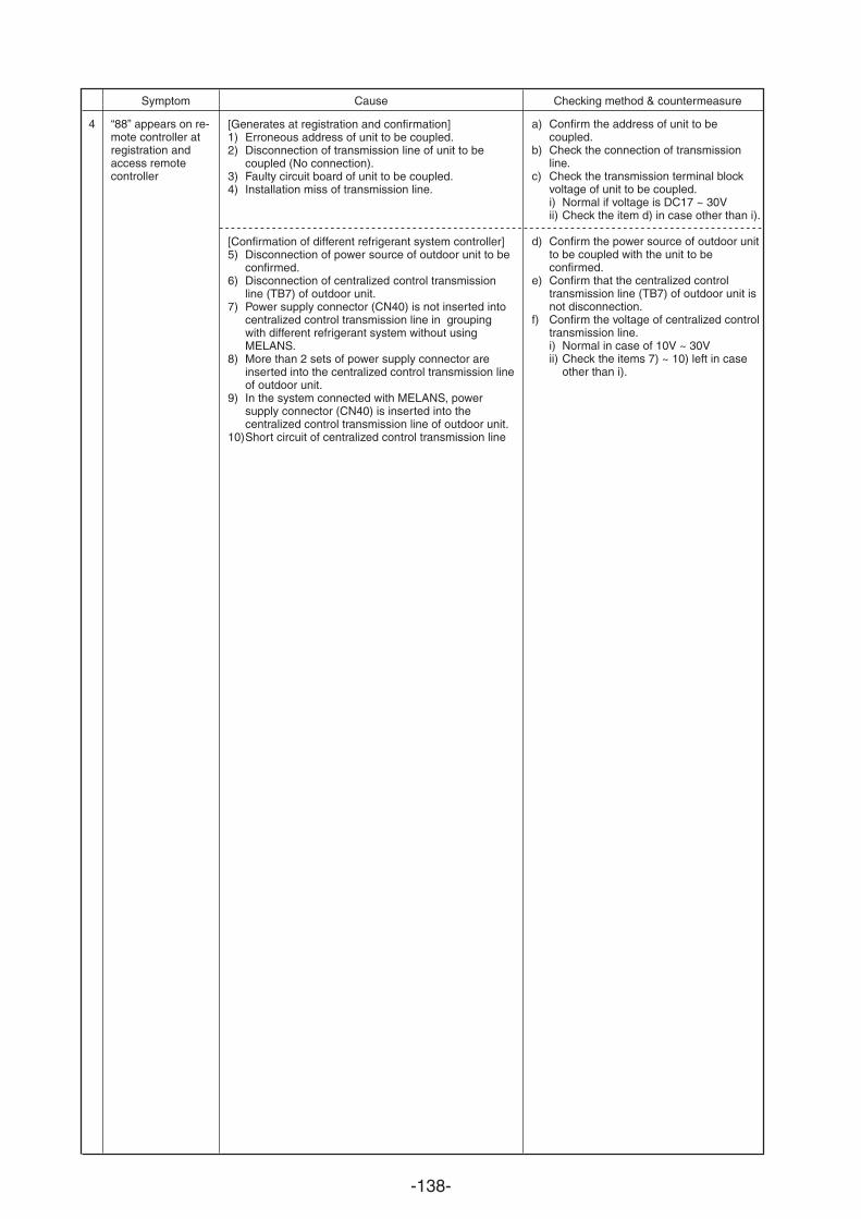
-138-
Symptom Cause Checking method & countermeasure
4 “88” appears on re-mote controller atregistration andaccess remotecontroller
a) Confirm the address of unit to becoupled.
b) Check the connection of transmissionline.
c) Check the transmission terminal blockvoltage of unit to be coupled.i) Normal if voltage is DC17 ~ 30Vii) Check the item d) in case other than i).
d) Confirm the power source of outdoor unitto be coupled with the unit to beconfirmed.
e) Confirm that the centralized controltransmission line (TB7) of outdoor unit isnot disconnection.
f) Confirm the voltage of centralized controltransmission line.i) Normal in case of 10V ~ 30Vii) Check the items 7) ~ 10) left in case
other than i).
[Generates at registration and confirmation]1) Erroneous address of unit to be coupled.2) Disconnection of transmission line of unit to be
coupled (No connection).3) Faulty circuit board of unit to be coupled.4) Installation miss of transmission line.
[Confirmation of different refrigerant system controller]5) Disconnection of power source of outdoor unit to be
confirmed.6) Disconnection of centralized control transmission
line (TB7) of outdoor unit.7) Power supply connector (CN40) is not inserted into
centralized control transmission line in groupingwith different refrigerant system without usingMELANS.
8) More than 2 sets of power supply connector areinserted into the centralized control transmission lineof outdoor unit.
9) In the system connected with MELANS, powersupply connector (CN40) is inserted into thecentralized control transmission line of outdoor unit.
10)Short circuit of centralized control transmission line
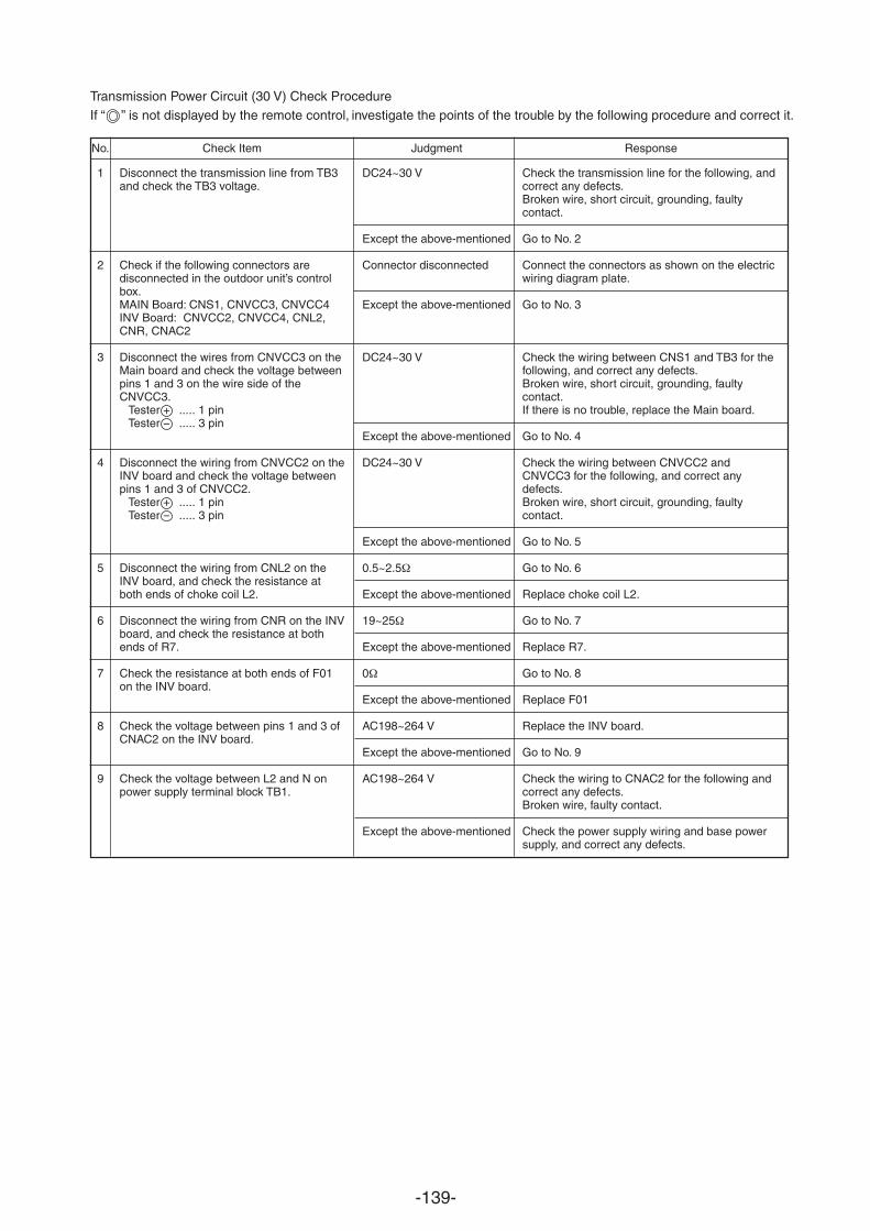
-139-
Transmission Power Circuit (30 V) Check ProcedureIf “ ” is not displayed by the remote control, investigate the points of the trouble by the following procedure and correct it.
No. Check Item Judgment Response
1
2
3
4
5
6
7
8
9
Disconnect the transmission line from TB3and check the TB3 voltage.
Check if the following connectors aredisconnected in the outdoor unit’s controlbox.MAIN Board: CNS1, CNVCC3, CNVCC4INV Board: CNVCC2, CNVCC4, CNL2,CNR, CNAC2
Disconnect the wires from CNVCC3 on theMain board and check the voltage betweenpins 1 and 3 on the wire side of theCNVCC3.
Tester + ..... 1 pinTester ..... 3 pin
Disconnect the wiring from CNVCC2 on theINV board and check the voltage betweenpins 1 and 3 of CNVCC2.
Tester ..... 1 pinTester ..... 3 pin
Disconnect the wiring from CNL2 on theINV board, and check the resistance atboth ends of choke coil L2.
Disconnect the wiring from CNR on the INVboard, and check the resistance at bothends of R7.
Check the resistance at both ends of F01on the INV board.
Check the voltage between pins 1 and 3 ofCNAC2 on the INV board.
Check the voltage between L2 and N onpower supply terminal block TB1.
DC24~30 V
Except the above-mentioned
Connector disconnected
Except the above-mentioned
DC24~30 V
Except the above-mentioned
DC24~30 V
Except the above-mentioned
0.5~2.5
Except the above-mentioned
19~25
Except the above-mentioned
0
Except the above-mentioned
AC198~264 V
Except the above-mentioned
AC198~264 V
Except the above-mentioned
Check the transmission line for the following, andcorrect any defects.Broken wire, short circuit, grounding, faultycontact.
Go to No. 2
Connect the connectors as shown on the electricwiring diagram plate.
Go to No. 3
Check the wiring between CNS1 and TB3 for thefollowing, and correct any defects.Broken wire, short circuit, grounding, faultycontact.If there is no trouble, replace the Main board.
Go to No. 4
Check the wiring between CNVCC2 andCNVCC3 for the following, and correct anydefects.Broken wire, short circuit, grounding, faultycontact.
Go to No. 5
Go to No. 6
Replace choke coil L2.
Go to No. 7
Replace R7.
Go to No. 8
Replace F01
Replace the INV board.
Go to No. 9
Check the wiring to CNAC2 for the following andcorrect any defects.Broken wire, faulty contact.
Check the power supply wiring and base powersupply, and correct any defects.
+
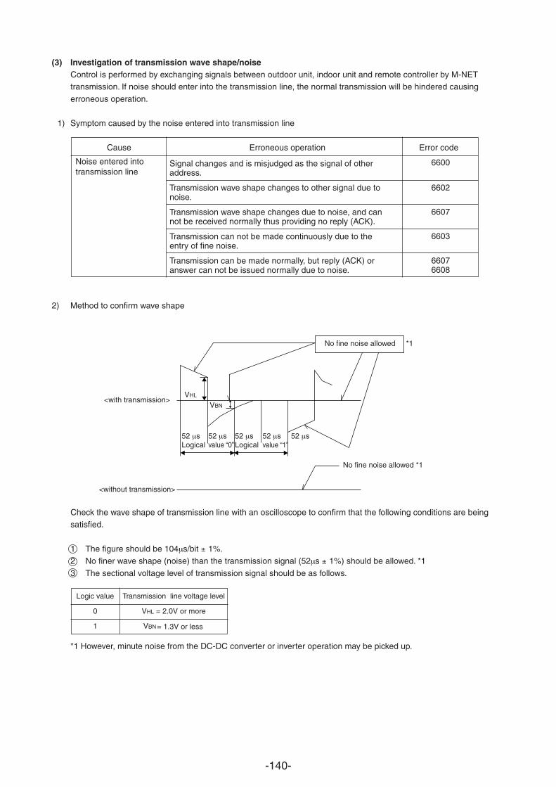
-140-
(3) Investigation of transmission wave shape/noiseControl is performed by exchanging signals between outdoor unit, indoor unit and remote controller by M-NETtransmission. If noise should enter into the transmission line, the normal transmission will be hindered causing
erroneous operation.
1) Symptom caused by the noise entered into transmission line
Cause Erroneous operation Error code
Signal changes and is misjudged as the signal of otheraddress.
Transmission wave shape changes to other signal due tonoise.
Transmission wave shape changes due to noise, and cannot be received normally thus providing no reply (ACK).
Transmission can not be made continuously due to theentry of fine noise.
Transmission can be made normally, but reply (ACK) oranswer can not be issued normally due to noise.
2) Method to confirm wave shape
Check the wave shape of transmission line with an oscilloscope to confirm that the following conditions are beingsatisfied.
1 The figure should be 104 s/bit 1%.2 No finer wave shape (noise) than the transmission signal (52 s 1%) should be allowed. *1
3 The sectional voltage level of transmission signal should be as follows.
*1 However, minute noise from the DC-DC converter or inverter operation may be picked up.
Noise entered intotransmission line
6600
6602
6607
6603
66076608
<with transmission>
<without transmission>
No fine noise allowed *1
No fine noise allowed *1
Logic value Transmission line voltage level
0 VHL = 2.0V or more
1 VBN
= 1.3V or less
VHL
VBN
52 sLogical
52 s52 sLogical
52 svalue “0”
52 svalue “1”
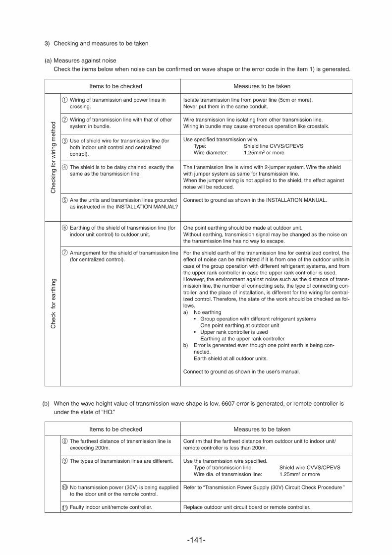
-141-
3) Checking and measures to be taken
(a) Measures against noise
Check the items below when noise can be confirmed on wave shape or the error code in the item 1) is generated.
Items to be checked Measures to be taken
(b) When the wave height value of transmission wave shape is low, 6607 error is generated, or remote controller isunder the state of “HO.”
Items to be checked Measures to be taken
Wiring of transmission and power lines incrossing.
Wiring of transmission line with that of othersystem in bundle.
Use of shield wire for transmission line (forboth indoor unit control and centralizedcontrol).
The shield is to be daisy chained exactly thesame as the transmission line.
Are the units and transmission lines groundedas instructed in the INSTALLATION MANUAL?
Earthing of the shield of transmission line (forindoor unit control) to outdoor unit.
Arrangement for the shield of transmission line(for centralized control).
Isolate transmission line from power line (5cm or more).Never put them in the same conduit.
Wire transmission line isolating from other transmission line.Wiring in bundle may cause erroneous operation like crosstalk.
Use specified transmission wire.Type: Shield line CVVS/CPEVSWire diameter: 1.25mm2 or more
The transmission line is wired with 2-jumper system. Wire the shieldwith jumper system as same for transmission line.When the jumper wiring is not applied to the shield, the effect againstnoise will be reduced.
Connect to ground as shown in the INSTALLATION MANUAL.
One point earthing should be made at outdoor unit.Without earthing, transmission signal may be changed as the noise onthe transmission line has no way to escape.
For the shield earth of the transmission line for centralized control, theeffect of noise can be minimized if it is from one of the outdoor units incase of the group operation with different refrigerant systems, and fromthe upper rank controller in case the upper rank controller is used.However, the environment against noise such as the distance of trans-mission line, the number of connecting sets, the type of connecting con-troller, and the place of installation, is different for the wiring for central-ized control. Therefore, the state of the work should be checked as fol-lows.a) No earthing
• Group operation with different refrigerant systemsOne point earthing at outdoor unit
• Upper rank controller is usedEarthing at the upper rank controller
b) Error is generated even though one point earth is being con-nected.Earth shield at all outdoor units.
Connect to ground as shown in the user’s manual.
Che
ck f
or e
arth
ing
Che
ckin
g fo
r w
iring
met
hod
The farthest distance of transmission line isexceeding 200m.
The types of transmission lines are different.
10 No transmission power (30V) is being suppliedto the idoor unit or the remote control.
11 Faulty indoor unit/remote controller.
Confirm that the farthest distance from outdoor unit to indoor unit/remote controller is less than 200m.
Use the transmission wire specified.Type of transmission line: Shield wire CVVS/CPEVSWire dia. of transmission line: 1.25mm2 or more
Refer to “Transmission Power Supply (30V) Circuit Check Procedure
.
”
Replace outdoor unit circuit board or remote controller.
1
2
3
4
5
6
7
8
9
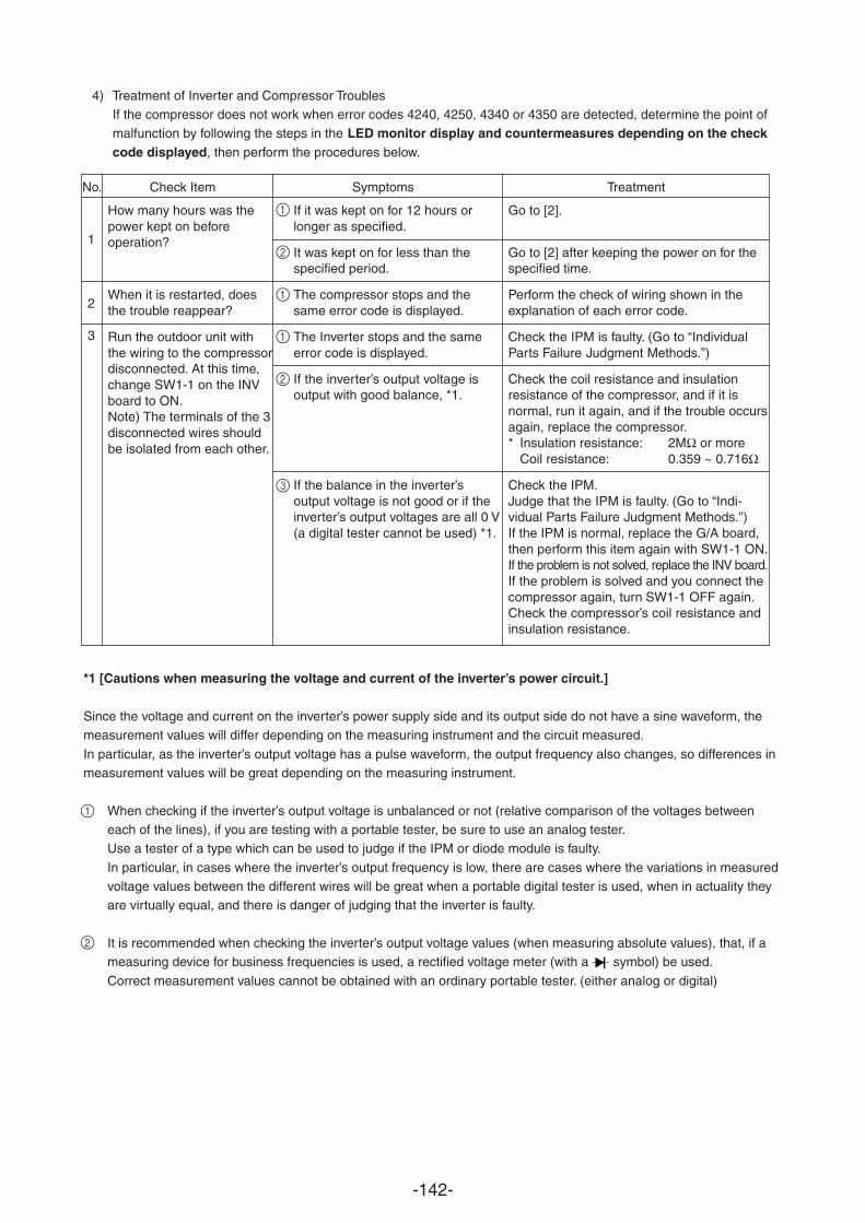
-142-
4) Treatment of Inverter and Compressor TroublesIf the compressor does not work when error codes 4240, 4250, 4340 or 4350 are detected, determine the point ofmalfunction by following the steps in the LED monitor display and countermeasures depending on the checkcode displayed, then perform the procedures below.
No. Check Item Symptoms Treatment
*1 [Cautions when measuring the voltage and current of the inverter’s power circuit.]
Since the voltage and current on the inverter’s power supply side and its output side do not have a sine waveform, themeasurement values will differ depending on the measuring instrument and the circuit measured.
In particular, as the inverter’s output voltage has a pulse waveform, the output frequency also changes, so differences inmeasurement values will be great depending on the measuring instrument.
When checking if the inverter’s output voltage is unbalanced or not (relative comparison of the voltages betweeneach of the lines), if you are testing with a portable tester, be sure to use an analog tester.Use a tester of a type which can be used to judge if the IPM or diode module is faulty.
In particular, in cases where the inverter’s output frequency is low, there are cases where the variations in measuredvoltage values between the different wires will be great when a portable digital tester is used, when in actuality theyare virtually equal, and there is danger of judging that the inverter is faulty.
It is recommended when checking the inverter’s output voltage values (when measuring absolute values), that, if ameasuring device for business frequencies is used, a rectified voltage meter (with a symbol) be used.
Correct measurement values cannot be obtained with an ordinary portable tester. (either analog or digital)
If it was kept on for 12 hours orlonger as specified.
It was kept on for less than thespecified period.
The compressor stops and thesame error code is displayed.
The Inverter stops and the sameerror code is displayed.
If the inverter’s output voltage isoutput with good balance, *1.
If the balance in the inverter’soutput voltage is not good or if theinverter’s output voltages are all 0 V(a digital tester cannot be used) *1.
Go to [2].
Go to [2] after keeping the power on for thespecified time.
Perform the check of wiring shown in theexplanation of each error code.
Check the IPM is faulty. (Go to “IndividualParts Failure Judgment Methods.”)
Check the coil resistance and insulationresistance of the compressor, and if it isnormal, run it again, and if the trouble occursagain, replace the compressor.* Insulation resistance: 2MΩ or more
Coil resistance: 0.359 ~ 0.716Ω
Check the IPM.Judge that the IPM is faulty. (Go to “Indi-vidual Parts Failure Judgment Methods.”)If the IPM is normal, replace the G/A board,then perform this item again with SW1-1 ON.If the problem is not solved, replace the INV board.If the problem is solved and you connect thecompressor again, turn SW1-1 OFF again.Check the compressor’s coil resistance andinsulation resistance.
How many hours was thepower kept on beforeoperation?
When it is restarted, doesthe trouble reappear?
Run the outdoor unit withthe wiring to the compressordisconnected. At this time,change SW1-1 on the INVboard to ON.Note) The terminals of the 3disconnected wires shouldbe isolated from each other.
1
2
3
1
2
1
1
2
3
1
2
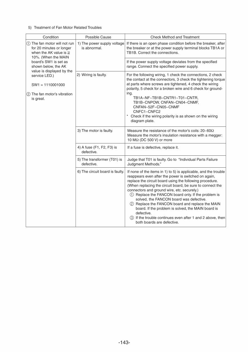
-143-
5) Treatment of Fan Motor Related Troubles
Condition Possible Cause Check Method and Treatment
The fan motor will not runfor 20 minutes or longerwhen the AK value is 10%. (When the MAINboard’s SW1 is set asshown below, the AKvalue is displayed by theservice LED.)
SW1 = 1110001000
The fan motor’s vibrationis great.
1) The power supply voltageis abnormal.
2) Wiring is faulty.
If there is an open phase condition before the breaker, afterthe breaker or at the power supply terminal blocks TB1A orTB1B. Correct the connections.
If the power supply voltage deviates from the specifiedrange. Connect the specified power supply.
For the following wiring, 1 check the connections, 2 checkthe contact at the connectors, 3 check the tightening torqueat parts where screws are tightened, 4 check the wiringpolarity, 5 check for a broken wire and 6 check for ground-ing.
TB1A~NF~TB1B~CNTR1~T01~CNTR,TB1B~CNPOW, CNFAN~CN04~CNMF,CNFAN~52F~CN05~CNMFCNFC1~CNFC2
* Check if the wiring polarity is as shown on the wiringdiagram plate.
3) The motor is faulty.
4) A fuse (F1, F2, F3) isdefective.
5) The transformer (T01) isdefective.
6) The circuit board is faulty.
Measure the resistance of the motor’s coils: 20~60Measure the motor’s insulation resistance with a megger:10 M (DC 500 V) or more
If a fuse is defective, replace it.
Judge that T01 is faulty. Go to “Individual Parts FailureJudgment Methods.”
If none of the items in 1) to 5) is applicable, and the troublereappears even after the power is switched on again,replace the circuit board using the following procedure.(When replacing the circuit board, be sure to connect theconnectors and ground wire, etc. securely.)
Replace the FANCON board only. If the problem issolved, the FANCON board was defective.Replace the FANCON board and replace the MAINboard. If the problem is solved, the MAIN board isdefective.If the trouble continues even after 1 and 2 above, thenboth boards are defective.
2
1
3
2
1
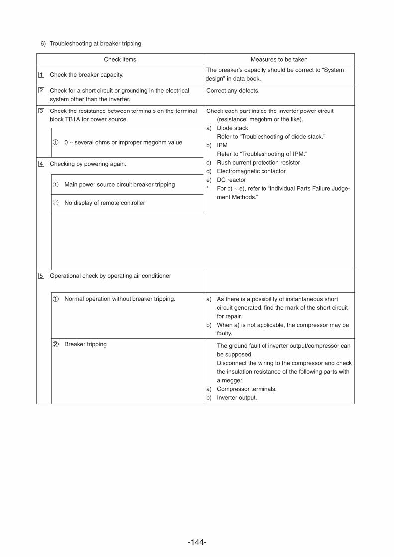
-144-
6) Troubleshooting at breaker tripping
Check items Measures to be taken
1 Check the breaker capacity.
Check for a short circuit or grounding in the electricalsystem other than the inverter.
Check the resistance between terminals on the terminalblock TB1A for power source.
Checking by powering again.
Operational check by operating air conditioner
The breaker’s capacity should be correct to “System
design” in data book.
Correct any defects.
Check each part inside the inverter power circuit(resistance, megohm or the like).
a) Diode stackRefer to “Troubleshooting of diode stack.”
b) IPM
Refer to “Troubleshooting of IPM.”c) Rush current protection resistord) Electromagnetic contactor
e) DC reactor* For c) ~ e), refer to “Individual Parts Failure Judge-
ment Methods.”
a) As there is a possibility of instantaneous shortcircuit generated, find the mark of the short circuitfor repair.
b) When a) is not applicable, the compressor may befaulty.
The ground fault of inverter output/compressor can
be supposed.Disconnect the wiring to the compressor and checkthe insulation resistance of the following parts with
a megger.a) Compressor terminals.b) Inverter output.
0 ~ several ohms or improper megohm value
Main power source circuit breaker tripping
No display of remote controller
1 Normal operation without breaker tripping.
2 Breaker tripping
3
4
5
2
1
1
2
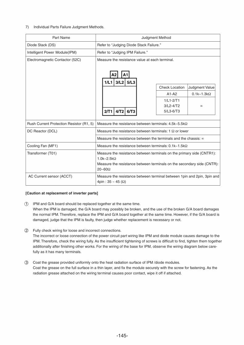
-145-
7) Individual Parts Failure Judgment Methods.
Part Name Judgment Method
Diode Stack (DS) Refer to “Judging Diode Stack Failure.”
Intelligent Power Module(IPM) Refer to “Judging IPM Failure.”
Electromagnetic Contactor (52C) Measure the resistance value at each terminal.
Rush Current Protection Resistor (R1, 5) Measure the resistance between terminals: 4.5k~5.5k
DC Reactor (DCL) Measure the resistance between terminals: 1 or lower
Measure the resistance between the terminals and the chassis:
Cooling Fan (MF1) Measure the resistance between terminals: 0.1k~1.5k
Transformer (T01) Measure the resistance between terminals on the primary side (CNTR1):
1.0k~2.5kMeasure the resistance between terminals on the secondary side (CNTR):20~60
AC Current sensor (ACCT) Measure the resistance between terminal between 1pin and 2pin, 3pin and4pin : 35 ~ 45 ( )
A1A2
1/L1 3/L2 5/L3
2/T1 4/T2 6/T3
Check Location Judgment Value
A1-A2 0.1k~1.3k
1/L1-2/T1
3/L2-4/T25/L3-6/T3
[Caution at replacement of inverter parts]
1 IPM and G/A board should be replaced together at the same time.
When the IPM is damaged, the G/A board may possibly be broken, and the use of the broken G/A board damagesthe normal IPM. Therefore, replace the IPM and G/A board together at the same time. However, if the G/A board isdamaged, judge that the IPM is faulty, then judge whether replacement is necessary or not.
2 Fully check wiring for loose and incorrect connections.The incorrect or loose connection of the power circuit part wiring like IPM and diode module causes damage to the
IPM. Therefore, check the wiring fully. As the insufficient tightening of screws is difficult to find, tighten them togetheradditionally after finishing other works. For the wiring of the base for IPM, observe the wiring diagram below care-fully as it has many terminals.
3 Coat the grease provided uniformly onto the heat radiation surface of IPM /diode modules.Coat the grease on the full surface in a thin layer, and fix the module securely with the screw for fastening. As the
radiation grease attached on the wiring terminal causes poor contact, wipe it off if attached.
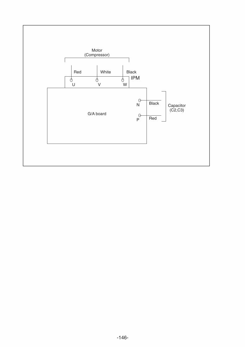
-146-
Motor(Compressor)
G/A board
Red
U V W
N
P
White Black
Black Capacitor(C2,C3)
Red
IPM
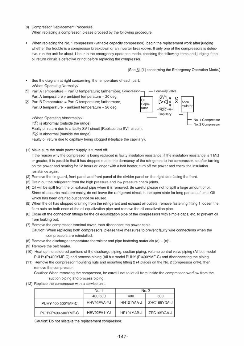
-147-
8) Compressor Replacement ProcedureWhen replacing a compressor, please proceed by the following procedure.
• When replacing the No. 1 compressor (variable capacity compressor), begin the replacement work after judgingwhether the trouble is a compressor breakdown or an inverter breakdown. If only one of the compressors is defec-tive, run the unit for about 1 hour in the emergency operation mode, checking the following items and judging if the
oil return circuit is defective or not before replacing the compressor.
(See 5 -[1] concerning the Emergency Operation Mode.)
• See the diagram at right concerning the temperature of each part.<When Operating Normally>
1 Part A Temperature = Part C temperature; furthermore,Part A temperature > ambient temperature + 20 deg.
2 Part B Temperature = Part C temperature; furthermore,
Part B temperature > ambient temperature + 20 deg.
<When Operating Abnormally>
If 1 is abnormal (outside the range),Faulty oil return due to a faulty SV1 circuit (Replace the SV1 circuit).If 2 is abnormal (outside the range),
Faulty oil return due to capillary being clogged (Replace the capillary).
(1) Make sure the main power supply is turned off.
If the reason why the compressor is being replaced is faulty insulation resistance, if the insulation resistance is 1 Mor greater, it is possible that it has dropped due to the dormancy of the refrigerant to the compressor, so after turningon the power and heating for 12 hours or longer with a belt heater, turn off the power and check the insulation
resistance again.(2) Remove the fin guard, front panel and front panel of the divider panel on the right side facing the front.(3) Drain out the refrigerant from the high pressure and low pressure check joints.
(4) Oil will be spilt from the oil exhaust pipe when it is removed. Be careful please not to spill a large amount of oil.Since oil absorbs moisture easily, do not leave the refrigerant circuit in the open state for long periods of time. Oilwhich has been drained out cannot be reused.
(5) When the oil has stopped draining from the refrigerant and exhaust oil outlets, remove fastening fitting 1 loosen theflare nuts on both ends of the oil equalization pipe and remove the oil equalization pipe.
(6) Close off the connection fittings for the oil equalization pipe of the compressors with simple caps, etc. to prevent oil
from leaking out.(7) Remove the compressor terminal cover, then disconnect the power cable.
Caution: When replacing both compressors, please take measures to prevent faulty wire connections when the
compressors are reinstalled.(8) Remove the discharge temperature thermistor and pipe fastening materials (a) ~ (e)*.(9) Remove the belt heater.
(10) Heat up the soldered portions of the discharge piping, suction piping, volume control valve piping (All but modelPUHY-(P)400YMF-C) and process piping (All but model PUHY-(P)400YMF-C) and disconnecting the piping.
(11) Remove the compressor mounting nuts and mounting fitting 2 (4 places on the No. 2 compressor only), then
remove the compressor.Caution: When removing the compressor, be careful not to let oil from inside the compressor overflow from the
suction piping and process piping.
(12) Replace the compressor with a service unit.
Caution: Do not mistake the replacement compressor.
SV1 A
B
C
Capillary
No. 1 CompressorNo. 2 Compressor
Accu-mulator
Compressor Four-way Valve
OilSepa-rator
No. 1400·500
HHV92FAA-YJ
HEV92FA1-YJ
No. 2
400 500
HH101YAA-J ZHC165YDA-J
HE101YAB-J ZEC165YAA-J
PUHY-400·500YMF-C
PUHY-P400·500YMF-C
-148-
(13) Solder the discharge piping, suction piping, volume control valve piping (All but model PUHY-(P)400YMF-C) andprocess piping (All but model PUHY-(P)400YMF-C).
(14) Attach the oil equalization pipe to both compressors. In the case of the PUHY-P-YMF-C, replace the dryer with a
new one. After replacing the dryer, do not leave the refrigerant circuit in the open state for a long period of time.
(15) Shut the ball valves (both the fluid side and gas side) on the outdoor unit and apply nitrogen from the high and lowpressure service check joint up to a pressure of A, checking to make sure there is no leakage.
(16) Discharge the nitrogen gas.(17) Open the ball valves (both the liquid side and gas side) on the outdoor unit and apply a vacuum.
(18) Install the belt heater.Caution: Do not mistake the belt heaters for the 2 compressors (particularly the PUHY-400 YMF-C).
(19) Install the pipe fasteners (a) ~ (d) in their original places.
Caution: If these fasteners are not mounted as they were originally, it could cause the pipe to crack during opera-tion, so install them securely.
(20) Mount the discharge temperature thermistor and attach the insulating cover.
(21) Connect the power cable to the compressor’s terminals.Caution: Be careful not to mistake the three phases. If the wires are connected wrong, it could damage the
compressor.
(22) When applying the vacuum is completed, charge the unit with the amount of refrigerant it was charged with at thefactory, and with the supplementary amount it was charged with when it was installed.
(23) After reconfirming the phase of the power cable wires at the compressors terminals, carry out an insulation
resistance check, then install the terminal cover and turn on the main power supply, checking if current is flowing tothe belt heater.Caution: When the ambient temperature is 5 C or lower, if you do not spend 4 hours with the power on to the
heater, the unit will not function even when the remote control is operated.(24) Make sure the liquid side and gas side ball values are opened.(25) Run all the indoor units and make sure they are operating normally.
2.94 MPa ------- PUHY-400·500 YMF-C2.98 MPa ----- PUHY-P400·500 YMF-C
*A =
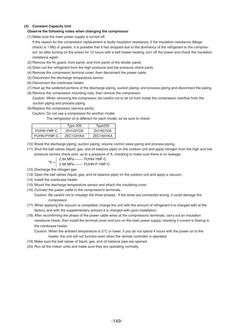
-149-
(4) Constant Capacity UnitObserve the following notes when changing the compressor
(1) Make sure the main power supply is turned off.
If the reason for the compressor replacement is faulty insulation resistance, if the insulation resistance (Mega-
check) is 1 M or greater, it is possible that it has dropped due to the dormancy of the refrigerant to the compres-sor, so after turning on the power for 12 hours with a belt heater heating, turn off the power and check the insulationresistance again.
(2) Remove the fin guard, front panel, and front panel of the divider panel.(3) Drain out the refrigerant from the high pressure and low pressure check joints.(4) Remove the compressor terminal cover, then disconnect the power cable.
(5) Disconnect the discharge temperature sensor.(6) Disconnect the crankcase heater.(7) Heat up the soldered portions of the discharge piping, suction piping, and process piping and disconnect the piping.
(8) Remove the compressor mounting nuts, then remove the compressor.Caution: When removing the compressor, be careful not to let oil from inside the compressor overflow from thesuction piping and process piping.
(9)Replace the compressor (service parts).Caution: Do not use a compressor for another model.
The refrigerator oil is different for each model, so be sure to check!
(10) Braze the discharge piping, suction piping, volume control valve piping and process piping.(11) Shut the ball valves (liquid, gas, and oil balance pipe) on the outdoor unit and apply nitrogen from the high and low
pressure service check joint, up to a pressure of A, checking to make sure there is no leakage.
(12) Discharge the nitrogen gas.(13) Open the ball valves (liquid, gas, and oil balance pipe) on the outdoor unit and apply a vacuum.(14) Install the crankcase heater
(15) Mount the discharge temperature sensor and attach the insulating cover.(16) Connect the power cable to the compressor’s terminals.
Caution: Be careful not to misalign the three phases. If the wires are connected wrong, it could damage the
compressor.(17) When applying the vacuum is completed, charge the unit with the amount of refrigerant it is charged with at the
factory, and with the supplementary amount it is charged with upon installation.
(18) After reconfirming the phase of the power cable wires at the compressors’ terminals, carry out an insulation
the crankcase heater.
Caution: When the ambient temperature is 5 C or lower, if you do not spend 4 hours with the power on to the
heater, the unit will not function even when the remote controller is operated.(19) Make sure the ball valves of liquid, gas, and oil balance pipe are opened.(20) Run all the indoor units and make sure they are operating normally.
2.94 MPa------- PUHN-YMF-C2.98 MPa------- PUHN-P-YMF-C
*A =
Type 200 Type250
PUHN-YMF-C ZH133YDA ZH165YDAPUHN-PYMF-C ZEC133YAA ZEC165YAA
resistance check, then install the terminal cover and turn on the main power supply, checking if current is flowing to
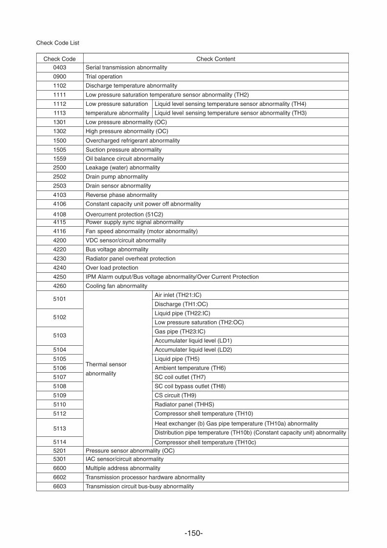
-150-
Check Code List
Check Code Check Content0403 Serial transmission abnormality
0900 Trial operation
1102 Discharge temperature abnormality
1111 Low pressure saturation temperature sensor abnormality (TH2)
1112 Low pressure saturation Liquid level sensing temperature sensor abnormality (TH4)
1113 temperature abnormality Liquid level sensing temperature sensor abnormality (TH3)
1301 Low pressure abnormality (OC)
1302 High pressure abnormality (OC)
1500 Overcharged refrigerant abnormality
1505 Suction
1559 Oil balance circuit abnormality
pressure abnormality
2500 Leakage (water) abnormality
2502 Drain pump abnormality
2503 Drain sensor abnormality
4103 Reverse
4106 Constant capacity unit power off abnormality
4108 Overcurrent protection (51C2)
phase abnormality
4115 Power supply sync signal abnormality
4116 Fan speed abnormality (motor abnormality)
4200 VDC sensor/circuit abnormality
4220 Bus voltage abnormality
4230 Radiator panel overheat protection
4240
4250 IPM Alarm output / Bus voltage abnormality / Over Current Protection
4260 Cooling fan abnormality
Air inlet (TH21:IC)5101
Discharge (TH1:OC)
Liquid pipe (TH22:IC)5102
Low pressure saturation (TH2:OC)
5103Gas pipe (TH23:IC)
Accumulater liquid level (LD1)
5104
Thermal sensor
Accumulater liquid level (LD2)
5105
abnormality
Liquid pipe (TH5)
5106 Ambient temperature (TH6)
5107 SC coil outlet (TH7)
5108 SC coil bypass outlet (TH8)
5109 CS circuit (TH9)
5110 Radiator panel (THHS)
5112
5113
5114
Compressor shell temperature (TH10)
5201 Pressure sensor abnormality (OC)
Heat exchanger (b) Gas pipe temperature (TH10a) abnormality
Distribution pipe temperature (TH10b) (Constant capacity unit) abnormality
Compressor shell temperature (TH10c)
5301 IAC sensor/circuit abnormality
6600 Multiple address abnormality
6602 Transmission processor hardware abnormality
6603 Transmission circuit bus-busy abnormality
Over load protection
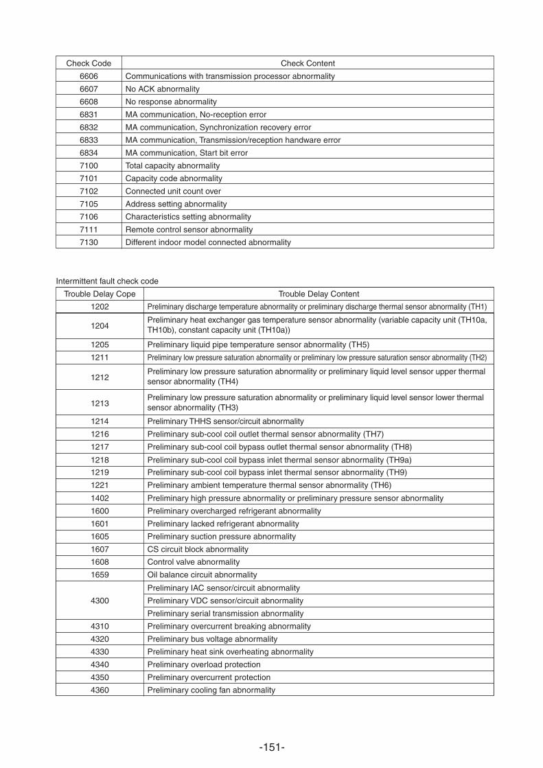
-151-
Check Code Check Content
6606 Communications with transmission processor abnormality
6607 No ACK abnormality
6608 No response abnormality
6831 MA communication, No-reception error
6832 MA communication, Synchronization recovery error
6833 MA communication, Transmission/reception handware error
6834 MA communication, Start bit error
7100 Total capacity abnormality
7101 Capacity code abnormality
7102 Connected unit count over
7105 Address setting abnormality
7106 Characteristics setting abnormality
7111 Remote control sensor abnormality
7130 Different indoor model connected abnormality
Intermittent fault check code
Trouble Delay Cope Trouble Delay Content
1202 Preliminar
1204Preliminary heat exchanger gas temperature sensor abnormality (variable capacity unit (TH10a, TH10b), constant capacity unit (TH10a))
1212Preliminary low pressure saturation abnormality or preliminary liquid level sensor upper thermal sensor abnormality (TH4)
1213Preliminary low pressure saturation abnormality or preliminary liquid level sensor lower thermal sensor abnormality (TH3)
y discharge temperature abnormality or preliminary discharge thermal sensor abnormality (TH1)
1205 Preliminary liquid pipe temperature sensor abnormality (TH5)
1211 Preliminary low pressure saturation abnormality or preliminary low pressure saturation sensor abnormality (TH2)
1214 Preliminary THHS sensor/circuit abnormality
1216 Preliminary sub-cool coil outlet thermal sensor abnormality (TH7)
1217 Preliminar
1218 Preliminary sub-cool coil bypass inlet thermal sensor abnormality (TH9a)
y sub-cool coil bypass outlet thermal sensor abnormality (TH8)
1219 Preliminary sub-cool coil bypass inlet thermal sensor abnormality (TH9)
1221 Preliminary ambient temperature thermal sensor abnormality (TH6)
1402 Preliminary high pressure abnormality or preliminary pressure sensor abnormality
1601
Preliminary 1600
Preliminary lacked refrigerant abnormality
overcharged refrigerant abnormality
1605 Preliminary suction pressure abnormality
1607 CS circuit b
1608 Control valve abnormality
1659 Oil balance circuit abnormality
lock abnormality
Preliminary IAC sensor/circuit abnormality
4300 Preliminary VDC sensor/circuit abnormality
Preliminary serial transmission abnormality
4320 Preliminary bus voltage abnormality
4310 Preliminary overcurrent breaking abnormality
4330 Preliminary heat sink overheating abnormality
4340 Preliminary overload protection
4350 Preliminary overcurrent protection
4360 Preliminary cooling fan abnormality
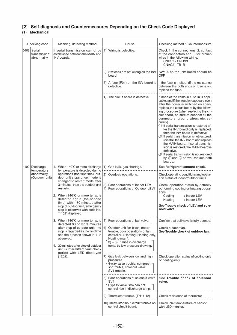
-152-
Checking code Meaning, detecting method Cause Checking method & Countermeasure
Serialtransmissionabnormality
0403 If serial transmission cannot beestablished between the MAIN andINV boards.
1) Wiring is defective.
2) Switches are set wrong on the INVboard.
3) A fuse (F01) on the INV board isdefective.
4) The circuit board is defective.
Check 1, the connections, 2, contactat the connectors and 3, for brokenwires in the following wiring.
CNRS2 - CNRS3CNAC2 - TB1B
SW1-4 on the INV board should beOFF.
If the fuse is melted, (if the resistancebetween the both ends of fuse is ),replace the fuse.
If none of the items in 1) to 3) is appli-cable, and if the trouble reappears evenafter the power is switched on again,replace the circuit board by the follow-ing procedure (when replacing the cir-cuit board, be sure to connect all theconnectors, ground wires, etc. se-curely).1 If serial transmission is restored af-
ter the INV board only is replaced,then the INV board is defective.
2 If serial transmission is not restored,reinstall the INV board and replacethe MAIN board. If serial transmis-sion is restored, the MAIN board isdefective.
3 If serial transmission is not restoredby 1 and 2 above, replace bothboards.
[2] Self-diagnosis and Countermeasures Depending on the Check Code Displayed(1) Mechanical
Dischargetemperatureabnormality(Outdoor unit)
1102 1. When 140˚C or more dischargetemperature is detected duringoperations (the first time), out-door unit stops once, mode ischanged to restart mode after3 minutes, then the outdoor unitrestarts.
2. When 140˚C or more temp. isdetected again (the secondtime) within 30 minutes afterstop of outdoor unit, emergencystop is observed with code No.“1102” displayed.
3. When 140˚C or more temp. isdetected 30 or more minutesafter stop of outdoor unit, thestop is regarded as the first timeand the process shown in 1 isobserved.
4. 30 minutes after stop of outdoorunit is intermittent fault checkperiod with LED displayed(1202).
See Refrigerant amount check.
Check operating conditions and opera-tion status of indoor/outdoor units.
Check operation status by actuallyperforming cooling or heating opera-tions.
Cooling : Indoor LEVHeating : Indoor LEV
See Trouble check of LEV and sole-noid valve.
1) Gas leak, gas shortage.
2) Overload operations.
3) Poor operations of indoor LEV.4) Poor operations of Outdoor LEV1
5) Poor operations of ball valve.
6) Outdoor unit fan block, motortrouble, poor operations of fancontroller Heating (Heating-only,Heating-main).3) ~ 6) : Rise in dischargetemp. by low pressure drawing.
7) Gas leak between low and highpressures.4-way valve trouble, compres-sor trouble, solenoid valveSV1 trouble.
8) Poor operations of solenoid valveSV4.Bypass valve SV4 can notcontrol rise in discharge temp.
9) Thermistor trouble. (TH11,12)
10)Thermistor input circuit trouble oncontrol circuit board.
Confirm that ball valve is fully opened.
Check outdoor fan.See Trouble check of outdoor fan.
Check operation status of cooling-onlyor heating-only.
See Trouble check of solenoidvalve.
Check resistance of thermistor.
Check inlet temperature of sensorwith LED monitor.
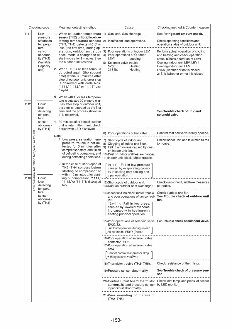
-153-
Checking code Meaning, detecting method Cause Checking method & Countermeasure
Lowpressuresaturationtempera-turesensorabnormal-ity (Variable Capacity unit)
(TH2)
Liquidleveldetectingtempera-turesensorabnormal-ity (TH4)
Liquidleveldetectingtempera-turesensorabnormal-ity (TH3)
1111
1112
1113
1. When saturation temperaturesensor (TH2) or liquid level de-tecting temperature sensors(TH3, TH4) detects -40˚C orless (the first time) during op-erations, outdoor unit stopsonce, mode is changed to re-start mode after 3 minutes, thenthe outdoor unit restarts.
2. When -40˚C or less temp. isdetected again (the secondtime) within 30 minutes afterstop of outdoor unit, error stopis observed with code Nos.“1111,” “1112,” or “1113” dis-played.
3. When -40˚C or less tempera-ture is detected 30 or more min-utes after stop of outdoor unit,the stop is regarded as the firsttime and the process shown in1. is observed.
4. 30 minutes after stop of outdoorunit is intermittent fault checkperiod with LED displayed.
Note:1. Low press. saturation tem-
perature trouble is not de-tected for 3 minutes aftercompressor start, and finishof defrosting operations, andduring defrosting operations.
2. In the case of short/open ofTH2~TH4 sensors beforestarting of compressor orwithin 10 minutes after start-ing of compressor, “1111,”“1112,” or “1113” is displayedtoo.
See Refrigerant amount check.
Check operating conditions and operation status of outdoor unit.
Perform actual operation of cooling and heating and check operation satus. (Check operation of LEV)Cooling-indoor unit LEV, LEV1Heating-indoor unit LEVSV5b (whether or not is closed)21S4b (whether or not it is closed)
1) Gas leak, Gas shortage.
2) Insufficient load operations.
3) Poor operations of indoor LEV.4) Poor operations of Outdoor
LEV1: 5) Solenoid valve trouble
5V5b:
Low
pre
ssur
e sa
tura
tion
tem
pera
ture
trou
ble
Confirm that ball valve is fully opened.
Check indoor unit, and take measu-resto troube.
Check outdoor unit, and take measuresto trouble.
Check outdoor unit fan.See Trouble check of outdoor unitfan.
See Trouble check of solenoid valve.
Check resistance of thermistor.
See Trouble check of pressure sen-sor.
Check inlet temp. and press. of sensorby LED monitor.
6) Poor operations of ball valve.
7) Short cycle of indoor unit.8) Clogging of indoor unit filter.9) Fall in air volume caused by dust
on indoor unit fan.10)Dust on indoor unit heat exchanger.11)Indoor unit block, Motor trouble.
9)~11) : Fall in low pressurecaused by evaporating capac-ity in cooling-only cooling-prin-cipal operation.
12)Short cycle of outdoor unit.13)Dust on outdoor heat exchanger.
14)Indoor unit fan block, motor trouble,and poor operations of fan control-ler.12)~14): Fall in low press.caus-ed by lowered evaporat-ing capa-city in heating-onlyheating-principal operation.
15)Poor operations of solenoid valveSV22/32.Full load operation during unload.All but model PUHY-(P)400.
Cannot control low pressor drop with bypass valve(SV4).
18)Thermistor trouble (TH2~TH6).
19)Pressure sensor abnor
16)Poor operation of solenoid valve contactor 52C2.
17)Poor operation of solenoid valveSV4.
mality.
20)Control circuit board thermistorabnormality and pressure sensorinput circuit abnormality.
21)Poor mounting of thermistor(TH2~TH6).
See Trouble check of LEV and solenoid valve.
cooding
Heating21S4b: Heating
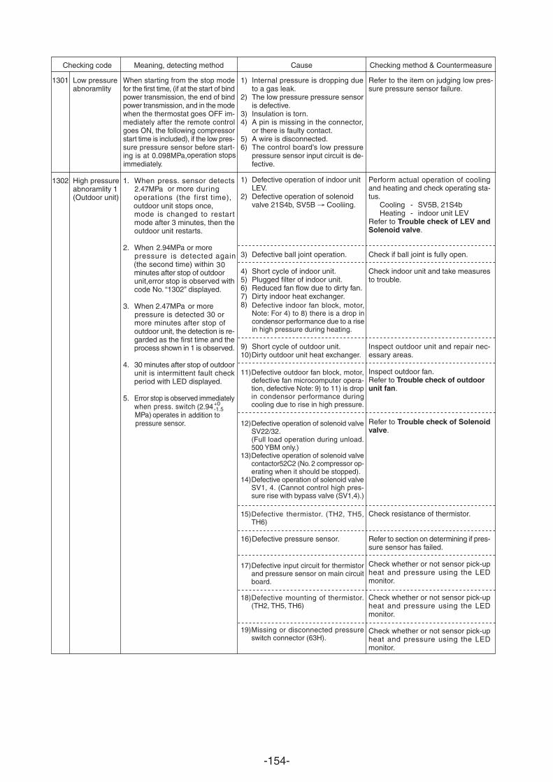
-154-
Checking code Meaning, detecting method Cause Checking method & Countermeasure
1301
1302
Low pressureabnoramlity
High pressureabnoramlity 1(Outdoor unit)
When starting from the stop modefor the first time, (if at the start of bindpower transmission, the end of bindpower transmission, and in the modewhen the thermostat goes OFF im-mediately after the remote controlgoes ON, the following compressorstart time is included), if the low pres-sure pressure sensor before start-ing is at 0.098MPa,operation stops immediately.
1. When press. sensor detects2.47MPa or moreoperations (the first time),outdoor unit stops once,mode is changed to restartmode after 3 minutes, then theoutdoor unit restarts.
2. When 2.94MPa or more pressure is detected again(the second time) withinminutes after stop of outdoorunit,error stop is observed withcode No. “1302” displayed.
3. When 2.47MPa or morepressure is detected 30 ormore minutes after stop ofoutdoor unit, the detection is re-garded as the first time and theprocess shown in 1 is observed.
4. 30 minutes after stop of outdoorunit is intermittent fault checkperiod with LED displayed.
5. Error stop is observed immediatelywhen press. switch (2.94 MPa) operates in addition to pressure sensor.
1) Internal pressure is dropping dueto a gas leak.
2) The low pressure pressure sensoris defective.
3) Insulation is torn.4) A pin is missing in the connector,
or there is faulty contact.5) A wire is disconnected.6) The control board’s low pressure
pressure sensor input circuit is de-fective.
Refer to the item on judging low pres-sure pressure sensor failure.
+0-1.5
Perform actual operation of coolingand heating and check operating sta-tus.
Cooling - SV5B, 21S4bHeating - indoor unit LEV
Refer to Trouble check of LEV andSolenoid valve.
Check if ball joint is fully open.
Check indoor unit and take measuresto trouble.
Inspect outdoor unit and repair nec-essary areas.
Inspect outdoor fan.Refer to Trouble check of outdoorunit fan.
Refer to Trouble check of Solenoidvalve.
Check resistance of thermistor.
Refer to section on determining if pres-sure sensor has failed.
Check whether or not sensor pick-upheat and pressure using the LEDmonitor.
Check whether or not sensor pick-upheat and pressure using the LEDmonitor.
Check whether or not sensor pick-upheat and pressure using the LEDmonitor.
1) Defective operation of indoor unitLEV.
2) Defective operation of solenoidvalve 21S4b, SV5B Cooliing.
3) Defective ball joint operation.
4) Short cycle of indoor unit.5) Plugged filter of indoor unit.6) Reduced fan flow due to dirty fan.7) Dirty indoor heat exchanger.8) Defective indoor fan block, motor,
Note: For 4) to 8) there is a drop incondensor performance due to a risein high pressure during heating.
9) Short cycle of outdoor unit.10)Dirty outdoor unit heat exchanger.
11)Defective outdoor fan block, motor,defective fan microcomputer opera-tion, defective Note: 9) to 11) is dropin condensor performance duringcooling due to rise in high pressure.
12)Defective operation of solenoid valveSV22/32.(Full load operation during unload.500 YBM only.)
13)Defective operation of solenoid valvecontactor52C2 (No. 2 compressor op-erating when it should be stopped).
14)Defective operation of solenoid valveSV1, 4. (Cannot control high pres-sure rise with bypass valve (SV1,4).)
15)Defective thermistor. (TH2, TH5,TH6)
16)Defective pressure sensor.
17)Defective input circuit for thermistorand pressure sensor on main circuitboard.
18)Defective mounting of thermistor.(TH2, TH5, TH6)
19)Missing or disconnected pressureswitch connector (63H).
during
30
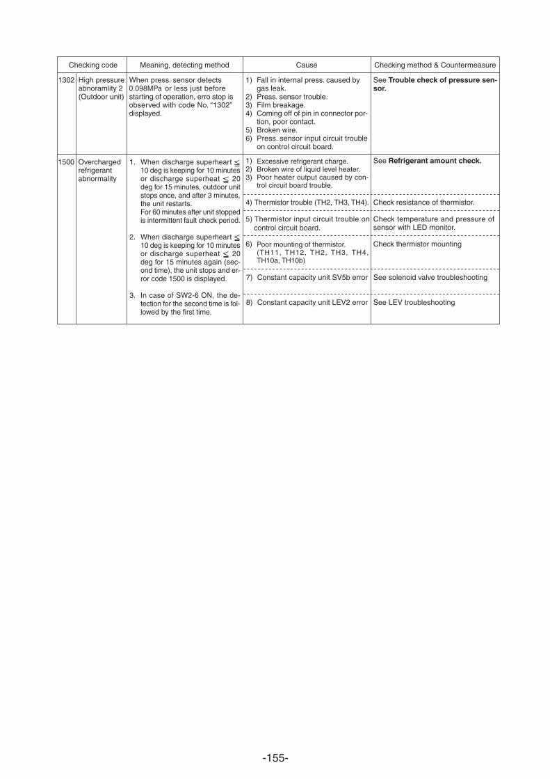
-155-
Checking code Meaning, detecting method Cause Checking method & Countermeasure
1302 High pressureabnoramlity 2(Outdoor unit)
When press. sensor detects 0.098MPa or less just beforestarting of operation, erro stop isobserved with code No. “1302”displayed.
1) Fall in internal press. caused bygas leak.
2) Press. sensor trouble.3) Film breakage.4) Coming off of pin in connector por-
tion, poor contact.5) Broken wire.6) Press. sensor input circuit trouble
on control circuit board.
See Trouble check of pressure sen-sor.
1500 1. When discharge superheart 10 deg is keeping for 10 minutesor discharge superheat 20deg for 15 minutes, outdoor unitstops once, and after 3 minutes,the unit restarts.For 60 minutes after unit stoppedis intermittent fault check period.
2. When discharge superheart 10 deg is keeping for 10 minutesor discharge superheat 20deg for 15 minutes again (sec-ond time), the unit stops and er-ror code 1500 is displayed.
3. In case of SW2-6 ON, the de-tection for the second time is fol-lowed by the first time.
Overchargedrefrigerantabnormality
Check resistance of thermistor.
Check temperature and pressure ofsensor with LED monitor.
Check thermistor mounting
See solenoid valve troubleshooting
1) Excessive refrigerant charge.2) Broken wire of liquid level heater.3) Poor heater output caused by con-
trol circuit board trouble.
6) Poor mounting of thermistor.(TH11, TH12, TH2, TH3, TH4,TH10a, TH10b)
7) Constant capacity unit SV5b error
8) Constant capacity unit LEV2 error
See Refrigerant amount check.
See LEV troubleshooting
5) Thermistor input circuit trouble on control circuit board.
4) Thermistor trouble (TH2, TH3, TH4).
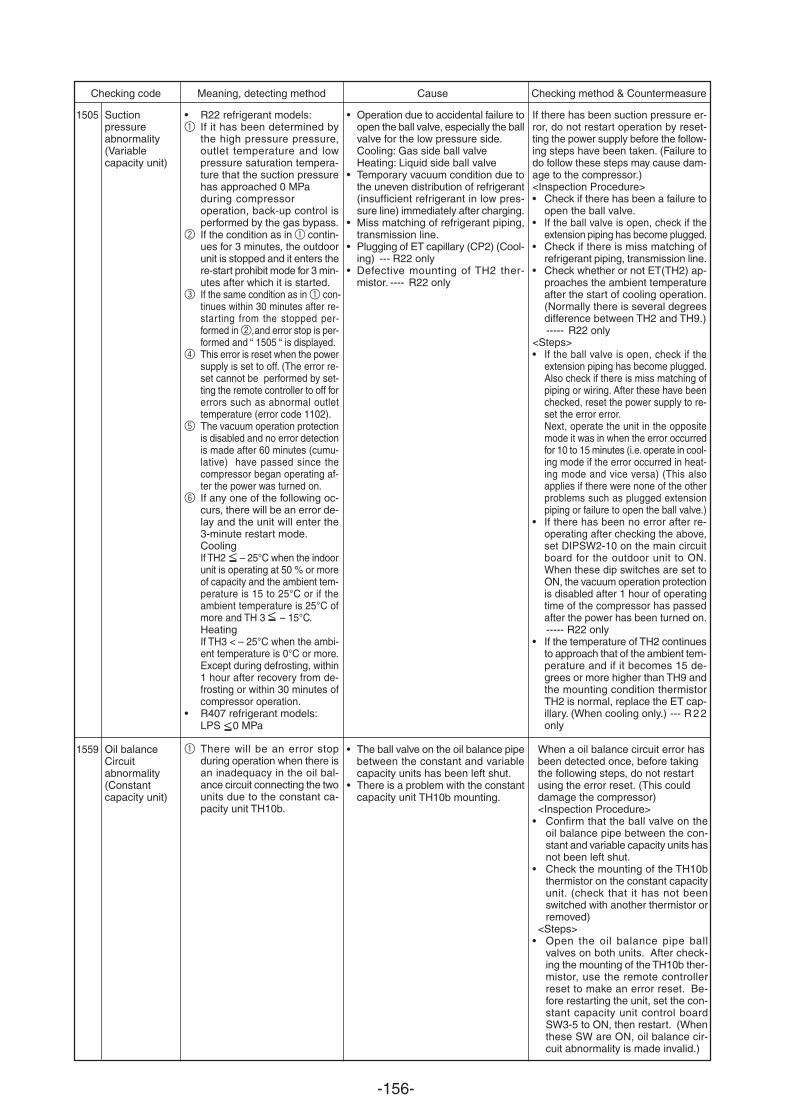
-156-
Checking code Meaning, detecting method Cause Checking method & Countermeasure
1505
1559
Suctionpressureabnormality(Variablecapacity unit)
Oil balanceCircuitabnormality(Constantcapacity unit)
• R22 refrigerant models:1 If it has been determined by
the high pressure pressure,outlet temperature and lowpressure saturation tempera-ture that the suction pressurehas approached 0 MPaduring compressor operation, back-up control isperformed by the gas bypass.
2 If the condition as in 1 contin-ues for 3 minutes, the outdoorunit is stopped and it enters there-start prohibit mode for 3 min-utes after which it is started.
3 If the same condition as in 1 con- tinues within 30 minutes after re-starting from the stopped per-formed in 2,and error stop is per-formed and “ 1505 “ is displayed.
4 This error is reset when the powersupply is set to off. (The error re-set cannot be performed by set-ting the remote controller to off forerrors such as abnormal outlettemperature (error code 1102).
5 The vacuum operation protectionis disabled and no error detectionis made after 60 minutes (cumu-lative) have passed since thecompressor began operating af-ter the power was turned on.
6 If any one of the following oc-curs, there will be an error de-lay and the unit will enter the3-minute restart mode.CoolingIf TH2 – 25 C when the indoorunit is operating at 50 % or moreof capacity and the ambient tem-perature is 15 to 25 C or if theambient temperature is 25 C ofmore and TH 3 – 15 C.HeatingIf TH3 < – 25 C when the ambi-ent temperature is 0 C or more.Except during defrosting, within1 hour after recovery from de-frosting or within 30 minutes ofcompressor operation.
• R407 refrigerant models:LPS 0 MPa
1 There will be an error stopduring operation when there isan inadequacy in the oil bal-ance circuit connecting the twounits due to the constant ca-pacity unit TH10b.
If there has been suction pressure er-ror, do not restart operation by reset-ting the power supply before the follow-ing steps have been taken. (Failure todo follow these steps may cause dam-age to the compressor.)<Inspection Procedure>• Check if there has been a failure to
open the ball valve.• If the ball valve is open, check if the
extension piping has become plugged.• Check if there is miss matching of
refrigerant piping, transmission line.• Check whether or not ET(TH2) ap-
proaches the ambient temperatureafter the start of cooling operation.(Normally there is several degreesdifference between TH2 and TH9.)----- R22 only
<Steps>• If the ball valve is open, check if the
extension piping has become plugged.Also check if there is miss matching ofpiping or wiring. After these have beenchecked, reset the power supply to re-set the error error.Next, operate the unit in the oppositemode it was in when the error occurredfor 10 to 15 minutes (i.e. operate in cool-ing mode if the error occurred in heat-ing mode and vice versa) (This alsoapplies if there were none of the otherproblems such as plugged extensionpiping or failure to open the ball valve.)
• If there has been no error after re-operating after checking the above,set DIPSW2-10 on the main circuitboard for the outdoor unit to ON.When these dip switches are set toON, the vacuum operation protectionis disabled after 1 hour of operatingtime of the compressor has passedafter the power has been turned on.----- R22 only
• If the temperature of TH2 continuesto approach that of the ambient tem-perature and if it becomes 15 de-grees or more higher than TH9 andthe mounting condition thermistorTH2 is normal, replace the ET cap-illary. (When cooling only.) --- R 2 2only
When a oil balance circuit error hasbeen detected once, before takingthe following steps, do not restartusing the error reset. (This coulddamage the compressor)<Inspection Procedure>
• Confirm that the ball valve on theoil balance pipe between the con-stant and variable capacity units hasnot been left shut.
• Check the mounting of the TH10bthermistor on the constant capacityunit. (check that it has not beenswitched with another thermistor orremoved)
<Steps>• Open the oil balance pipe ball
valves on both units. After check-ing the mounting of the TH10b ther-mistor, use the remote controllerreset to make an error reset. Be-fore restarting the unit, set the con-stant capacity unit control boardSW3-5 to ON, then restart. (Whenthese SW are ON, oil balance cir-cuit abnormality is made invalid.)
• Operation due to accidental failure toopen the ball valve, especially the ballvalve for the low pressure side.Cooling: Gas side ball valveHeating: Liquid side ball valve
• Temporary vacuum condition due tothe uneven distribution of refrigerant(insufficient refrigerant in low pres-sure line) immediately after charging.
• Miss matching of refrigerant piping,transmission line.
• Plugging of ET capillary (CP2) (Cool-ing) --- R22 only
• Defective mounting of TH2 ther-mistor. ---- R22 only
• The ball valve on the oil balance pipebetween the constant and variablecapacity units has been left shut.
• There is a problem with the constantcapacity unit TH10b mounting.
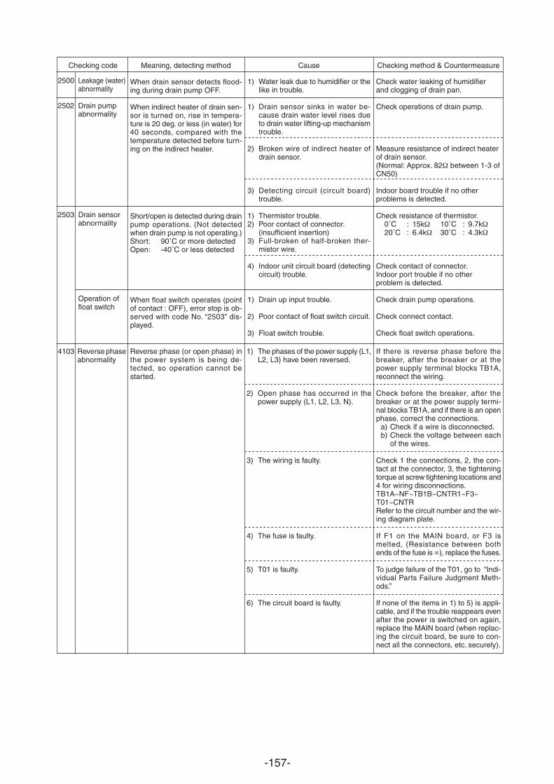
-157-
Checking code Meaning, detecting method Cause Checking method & Countermeasure
When drain sensor detects flood-ing during drain pump OFF.
When indirect heater of drain sen-sor is turned on, rise in tempera-ture is 20 deg. or less (in water) for40 seconds, compared with thetemperature detected before turn-ing on the indirect heater.
Short/open is detected during drainpump operations. (Not detectedwhen drain pump is not operating.)Short: 90˚C or more detectedOpen: -40˚C or less detected
When float switch operates (pointof contact : OFF), error stop is ob-served with code No. “2503” dis-played.
1) Water leak due to humidifier or thelike in trouble.
1) Drain sensor sinks in water be-cause drain water level rises dueto drain water lifting-up mechanismtrouble.
2) Broken wire of indirect heater ofdrain sensor.
3) Detecting circuit (circuit board)trouble.
1) Thermistor trouble.2) Poor contact of connector.
(insufficient insertion)3) Full-broken of half-broken ther-
mistor wire.
4) Indoor unit circuit board (detectingcircuit) trouble.
1) Drain up input trouble.
2) Poor contact of float switch circuit.
3) Float switch trouble.
Check water leaking of humidifierand clogging of drain pan.
Check operations of drain pump.
Measure resistance of indirect heaterof drain sensor.(Normal: Approx. 82 between 1-3 ofCN50)
Indoor board trouble if no otherproblems is detected.
Check resistance of thermistor.0˚C : 15k 10˚C : 9.7k20˚C : 6.4k 30˚C : 4.3k
Check contact of connector.Indoor port trouble if no otherproblem is detected.
Check drain pump operations.
Check connect contact.
Check float switch operations.
Leakage (water)abnormality
Drain pumpabnormality
Drain sensorabnormality
Operation offloat switch
2500
2502
2503
4103 Reverse phaseabnormality
Reverse phase (or open phase) inthe power system is being de-tected, so operation cannot bestarted.
1) The phases of the power supply (L1,L2, L3) have been reversed.
2) Open phase has occurred in thepower supply (L1, L2, L3, N).
3) The wiring is faulty.
4) The fuse is faulty.
5) T01 is faulty.
6) The circuit board is faulty.
If there is reverse phase before thebreaker, after the breaker or at thepower supply terminal blocks TB1A,reconnect the wiring.
Check before the breaker, after thebreaker or at the power supply termi-nal blocks TB1A, and if there is an openphase, correct the connections.
a) Check if a wire is disconnected.b) Check the voltage between each
of the wires.
Check 1 the connections, 2, the con-tact at the connector, 3, the tighteningtorque at screw tightening locations and4 for wiring disconnections.TB1A~NF~TB1B~CNTR1~F3~T01~CNTRRefer to the circuit number and the wir-ing diagram plate.
If F1 on the MAIN board, or F3 ismelted, (Resistance between bothends of the fuse is ), replace the fuses.
To judge failure of the T01, go to “Indi-vidual Parts Failure Judgment Meth-ods.”
If none of the items in 1) to 5) is appli-cable, and if the trouble reappears evenafter the power is switched on again,replace the MAIN board (when replac-ing the circuit board, be sure to con-nect all the connectors, etc. securely).
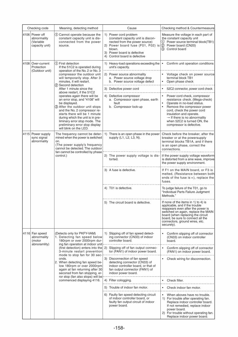
-158-
1) Power cord problem(constant capacity unit is discon-nected from the power source)
2) Power board fuse (F01, F02) isblown.
3) Power board is defective4) Control board is defective
1) Heavy-load operations exceeding theunit’s capacity.
2) Power source abnormalitya. Power source voltage dropb. Power source voltage defect
3) Defective power cord
4) Defective compressora. Compressor open phase, earth
faultb. Compressor lock-up
1) There is an open phase in the powersupply (L1, L2, L3, N).
2) The power supply voltage is dis-torted.
3) A fuse is defective.
4) T01 is defective.
5) The circuit board is defective.
Checking code Meaning, detecting method Cause Checking method & Countermeasure
4106
4108
4115
Power offabnormality(Variablecapacity unit)
Over-currentProtection(Outdoor unit)
Power supplysync signalabnormality
1 Cannot operate because theconstant capacity unit is dis-connected from the powersource.
1 First detectionIf the 51C2 is operated duringoperation of the No. 2 or No. 3compressor the outdoor unitwill temporarily stop. After 3minutes, it will restart.
2 Second detectionAfter 1 minute since theabove restart, if the 51C2operates again there will bean error stop, and “4108” willbe displayed.
3 After the outdoor unit stopsand the No. 2 compressor re-starts there will be 1 minuteduring which the unit is in pre-liminary error stop mode. Thepreliminary error stop displaywill blink on the LED.
The frequency cannot be deter-mined when the power is switchedon.(The power supply’s frequencycannot be detected. The outdoorfan cannot be controlled by phasecontrol.)
Measure the voltage in each part ofthe constant capacity unit12 Power board (CN20)3 Control board
• Confirm unit operation conditions
• Voltage check on power sourceterminal block TB1
• Open phase check
•
• Power cord check, compressor resistance check. (Mega-check)
• Operate in no-load status.• Remove the compressor power
cord, check the power cordinsulation and operate.
If there is no abnormalitywhen 52C2 is turned ON, thecompressor is defective.
the power supply voltage waveformis distorted from a sine wave, improvethe power supply environment.
If none of the items in 1) to 4) is applicable, and if the trouble reappears even after the power is switched on again, replace the MAIN board (when replacing the circuit board, be sure to connect all the connectors, ground wires, etc. securely).
4116 Fan speedabnormality(motorabnoramlity)
(Detects only for PKFY-VAM)1. Detecting fan speed below
180rpm or over 2000rpm dur-ing fan operation at indoor unit(first detection) enters into the3-minute restart preventionmode to stop fan for 30 sec-onds.
2. When detecting fan speed be-low 180rpm or over 2000rpmagain at fan returning after 30seconsd from fan stopping, er-ror stop (fan also stops) will becommenced displaying 4116.
1) Slipping off of fan speed detect-ing connector (CN33) of indoorcontroller board.
2) Slipping off of fan output connec-tor (FAN1) of indoor power board.
3) Disconnection of fan speeddetecting connector (CN33) ofindoor controller board, or that offan output connector (FAN1) ofindoor power board.
4) Filter cologging.
5) Trouble of indoor fan motor.
6) Faulty fan speed detecting circuitof indoor controller board, orfaulty fan output circuit of indoorpower board.
• Confirm slipping off of connector(CN33) on indoor controllerboard.
• Confirm slipping off of connector(FAN1) on indoor power board.
• Check wiring for disconnection.
• Check filter.
• Check indoor fan motor.
• When aboves have no trouble.1) For trouble after operating fan.
Replace indoor controller board. If not remedied, replace indoorpower board.
2) For trouble without operating fan.Replace indoor power board.
Check before the breaker, after thebreaker or at the powersupply terminal blocks TB1A, and if there is an open phase, correct the connections.
52C2 connector, power cord check
Power source terminal block(TB1)
To judge failure of the T01, go to “Individual Parts Failure Judgment Methods.”
If F1 on the MAIN board, or F3 ismelted, (Resistance between bothends of the fuse is ), replace the fuses.
If
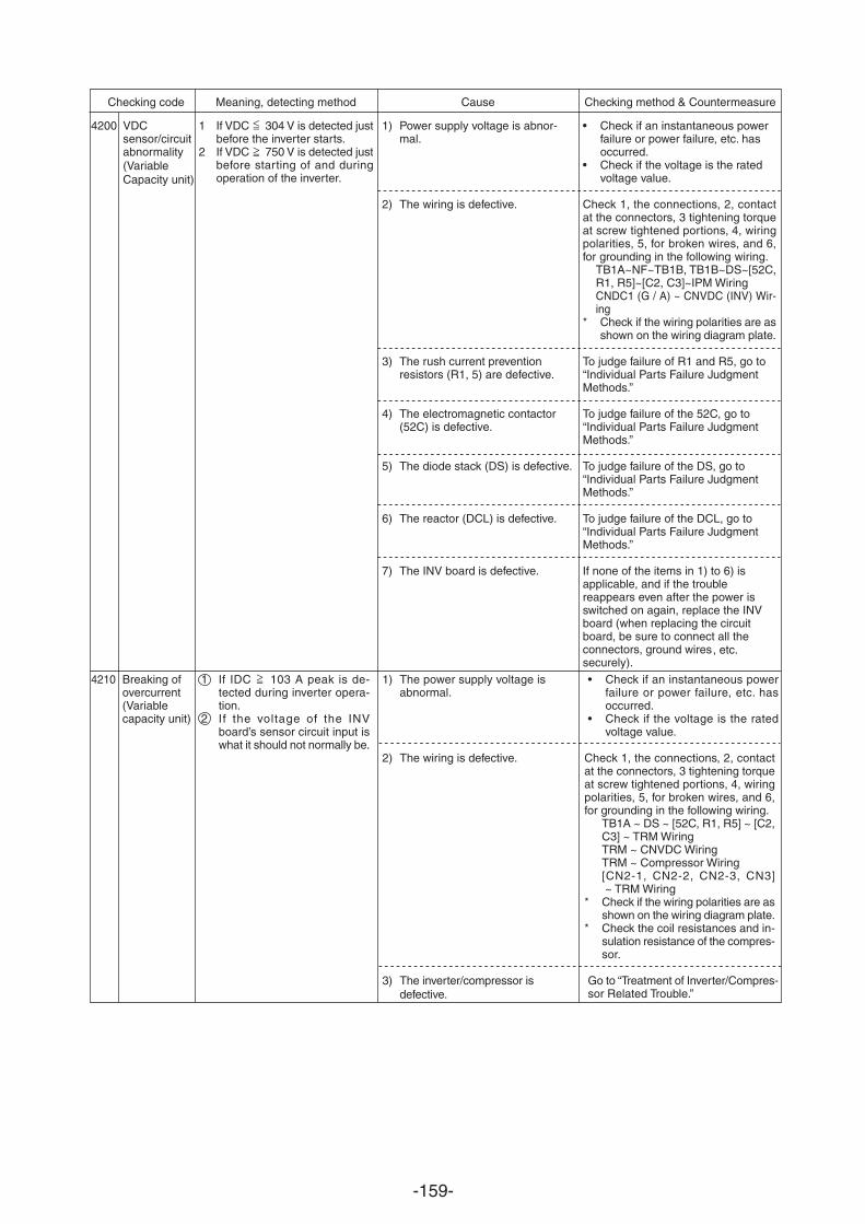
-159-
Checking code Meaning, detecting method Cause Checking method & Countermeasure
4200 VDCsensor/circuitabnormality(Variable Capacity unit)
1 If VDC 304 V is detected justbefore the inverter starts.
2 If VDC 750 V is detected justbefore starting of and duringoperation of the inverter.
1) Power supply voltage is abnor-mal.
2) The wiring is defective.
3) The rush current preventionresistors (R1, 5) are defective.
4) The electromagnetic contactor(52C) is defective.
5) The diode stack (DS) is defective.
6) The reactor (DCL) is defective.
7) The INV board is defective.
• Check if an instantaneous powerfailure or power failure, etc. hasoccurred.
• Check if the voltage is the ratedvoltage value.
Check 1, the connections, 2, contactat the connectors, 3 tightening torqueat screw tightened portions, 4, wiringpolarities, 5, for broken wires, and 6,for grounding in the following wiring.
TB1A~NF~TB1B, TB1B~DS~[52C,R1, R5]~[C2, C3]~IPM WiringCNDC1 (G / A) ~ CNVDC (INV) Wir-ing
* Check if the wiring polarities are asshown on the wiring diagram plate.
To judge failure of R1 and R5, go to“Individual Parts Failure JudgmentMethods.”
To judge failure of the 52C, go to“Individual Parts Failure JudgmentMethods.”
To judge failure of the DS, go to“Individual Parts Failure JudgmentMethods.”
To judge failure of the DCL, go to“Individual Parts Failure JudgmentMethods.”
If none of the items in 1) to 6) isapplicable, and if the troublereappears even after the power isswitched on again, replace the INVboard (when replacing the circuitboard, be sure to connect all theconnectors, ground wires, etc.securely).
4210 Breaking ofovercurrent(Variablecapacity unit)
1 If IDC 103 A peak is de-tected during inverter opera-tion.
2 If the voltage of the INVboard’s sensor circuit input iswhat it should not normally be.
• Check if an instantaneous powerfailure or power failure, etc. hasoccurred.
• Check if the voltage is the ratedvoltage value.
Check 1, the connections, 2, contactat the connectors, 3 tightening torqueat screw tightened portions, 4, wiringpolarities, 5, for broken wires, and 6,for grounding in the following wiring.
TB1A ~ DS ~ [52C, R1, R5] ~ [C2,C3] ~ TRM WiringTRM ~ CNVDC WiringTRM ~ Compressor Wiring[CN2-1, CN2-2, CN2-3, CN3] ~ TRM Wiring
* Check if the wiring polarities are asshown on the wiring diagram plate.
* Check the coil resistances and in-sulation resistance of the compres-sor.
Go to “Treatment of Inverter/Compres-sor Related Trouble.”
1) The power supply voltage is abnormal.
2) The wiring is defective.
3) The inverter/compressor is defective.
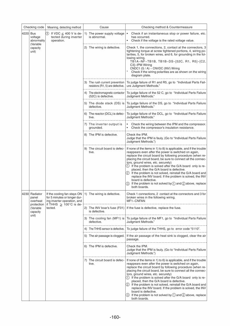
-160-
4220
4230
Busvoltageabnormality(Variablecapacity unit)
Radiatorpaneloverheatprotection(Variablecapacity unit)
1 If VDC 400 V is de-tected during inverteroperation.
If the cooling fan stays ONfor 5 minutes or longer dur-ing inverter operation, andif THHS 100 C is de-tected.
1) The power supply voltageis abnormal.
2) The wiring is defective.
3) The rush current preventionresistors (R1, 5) are defective.
4) The electromagnetic contactor(52C) is defective.
5) The diode stack (DS) isdefective.
6) The reactor (DCL) is defec-tive.
7) The inver ter output isgrounded.
8) The IPM is defective.
9) The circuit board is defec-tive.
1) The wiring is defective.
2) The INV boar’s fuse (F01)is defective.
3) The cooling fan (MF1) isdefective.
4) The THHS sensor is defective.
5) The air passage is clogged.
6) The IPM is defective.
7) The circuit board is defec-tive.
• Check if an instantaneous stop or power failure, etc.has occurred.
• Check if the voltage is the rated voltage value.
Check 1, the connections, 2, contact at the connectors, 3tightening torque at screw tightened portions, 4, wiring po-larities, 5, for broken wires, and 6, for grounding in the fol-lowing wiring.
TB1A~NF~TB1B, TB1B~DS~[52C, R1, R5]~[C2,C3]~IPM WiringCNDC1 (G / A) ~ CNVDC (INV) Wiring
* Check if the wiring polarities are as shown on the wiringdiagram plate.
To judge failure of R1 and R5, go to “Individual Parts Fail-ure Judgment Methods.”
To judge failure of the 52 C, go to “Individual Parts FailureJudgment Methods.”
To judge failure of the DS, go to “Individual Parts FailureJudgment Methods.”
To judge failure of the DCL, go to “Individual Parts FailureJudgment Methods.”
• Check the wiring between the IPM and the compressor.• Check the compressor’s insulation resistance.
Check the IPM.Judge that the IPM is fauly, (Go to “Individual Parts FailureJudgment Methods.”)
If none of the items in 1) to 8) is applicable, and if the troublereappears even after the power is switched on again,replace the circuit board by following procedure (when re-placing the circuit board, be sure to connect all the connec-tors, ground wires, etc. securety)
If the problem is solved after the G/A board only is re-placed, then the G/A board is defective.If the problem is not solved, reinstall the G/A board andreplace the INV board. If the problem is solved, the INVboard is defective.If the problem is not solved by and above, replaceboth boards.
Check 1 connections, 2 contact at the connectors and 3 forbroken wires in the following wiring.MF1~CNFAN
If the fuse is defective, replace the fuse.
To judge failure of the MF1, go to “Individual Parts FailureJudgment Methods.”
To judge failure of the THHS, go to error code “5110”.
If the air passage of the heat sink is clogged, clear the airpassage.
Check the IPM.Judge that the IPM is fauly, (Go to “Individual Parts FailureJudgment Methods.”)
If none of the items in 1) to 6) is applicable, and if the troublereappears even after the power is switched on again,replace the circuit board by following procedure (when re-placing the circuit board, be sure to connect all the connec-tors, ground wires, etc. securety)
If the problem is solved after the G/A board only is re-placed, then the G/A board is defective.If the problem is not solved, reinstall the G/A board andreplace the INV board. If the problem is solved, the INVboard is defective.If the problem is not solved by and above, replaceboth boards.
Checking code Meaning, detecting method Cause Checking method & Countermeasure
1
2
3 1 2
1
2
3 1 2
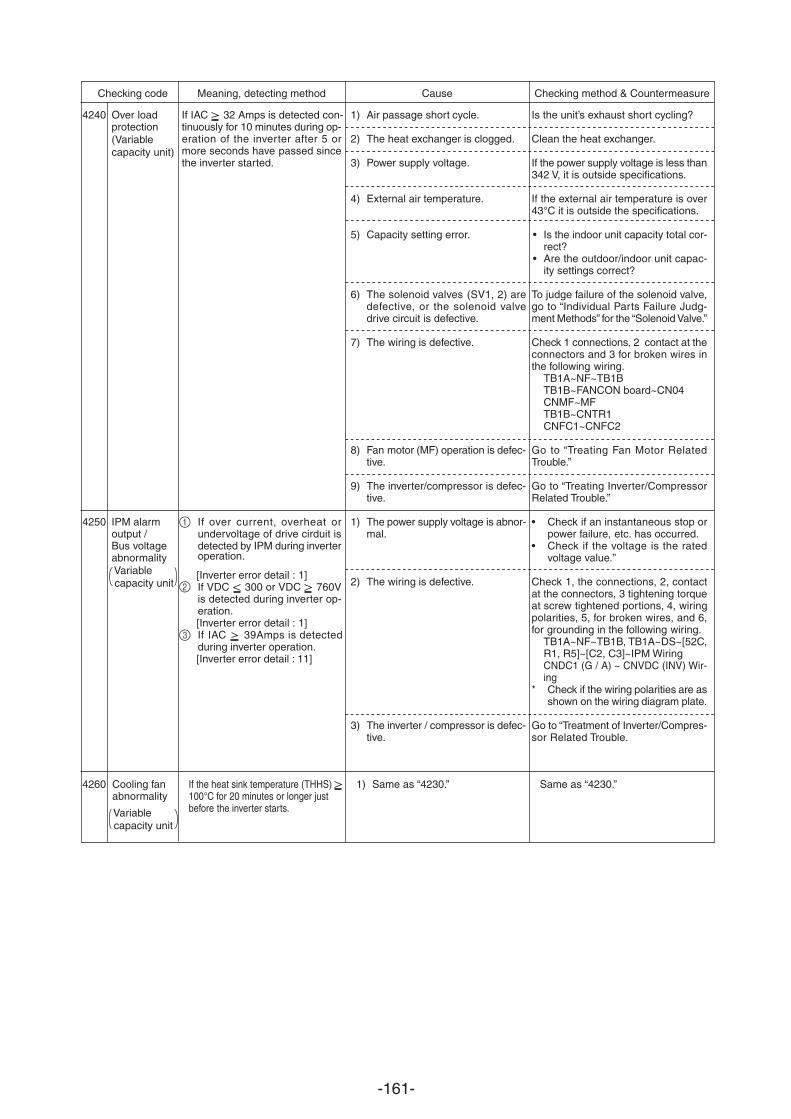
-161-
Checking code Meaning, detecting method Cause Checking method & Countermeasure
4240
4250
Over loadprotection(Variable capacity unit)
IPM alarmoutput /Bus voltageabnormality Variable capacity unit
If IAC 32 Amps is detected con-tinuously for 10 minutes during op-eration of the inverter after 5 ormore seconds have passed sincethe inverter started.
If over current, overheat orundervoltage of drive cirduit isdetected by IPM during inverteroperation.
[Inverter error detail : 1]If VDC 300 or VDC 760Vis detected during inverter op-eration.[Inverter error detail : 1]If IAC 39Amps is detectedduring inverter operation.[Inverter error detail : 11]
1) Air passage short cycle.
2) The heat exchanger is clogged.
3) Power supply voltage.
4) External air temperature.
5) Capacity setting error.
6) The solenoid valves (SV1, 2) aredefective, or the solenoid valvedrive circuit is defective.
7) The wiring is defective.
8) Fan motor (MF) operation is defec-tive.
9) The inverter/compressor is defec-tive.
1) The power supply voltage is abnor-mal.
2) The wiring is defective.
3) The inverter / compressor is defec-tive.
Is the unit’s exhaust short cycling?
Clean the heat exchanger.
If the power supply voltage is less than342 V, it is outside specifications.
If the external air temperature is over43 C it is outside the specifications.
• Is the indoor unit capacity total cor-rect?
• Are the outdoor/indoor unit capac-ity settings correct?
To judge failure of the solenoid valve,go to “Individual Parts Failure Judg-ment Methods” for the “Solenoid Valve.”
Check 1 connections, 2 contact at theconnectors and 3 for broken wires inthe following wiring.
TB1A~NF~TB1BTB1B~FANCON board~CN04CNMF~MFTB1B~CNTR1CNFC1~CNFC2
Go to “Treating Fan Motor RelatedTrouble.”
Go to “Treating Inverter/CompressorRelated Trouble.”
• Check if an instantaneous stop orpower failure, etc. has occurred.
• Check if the voltage is the ratedvoltage value.”
Check 1, the connections, 2, contactat the connectors, 3 tightening torqueat screw tightened portions, 4, wiringpolarities, 5, for broken wires, and 6,for grounding in the following wiring.
TB1A~NF~TB1B, TB1A~DS~[52C,R1, R5]~[C2, C3]~IPM WiringCNDC1 (G / A) ~ CNVDC (INV) Wir-ing
* Check if the wiring polarities are asshown on the wiring diagram plate.
Go to “Treatment of Inverter/Compres-sor Related Trouble.
4260 Cooling fanabnormality
If the heat sink temperature (THHS) 100 C for 20 minutes or longer justbefore the inverter starts.
Same as “4230.”1) Same as “4230.”
Variable capacity unit
1
2
3
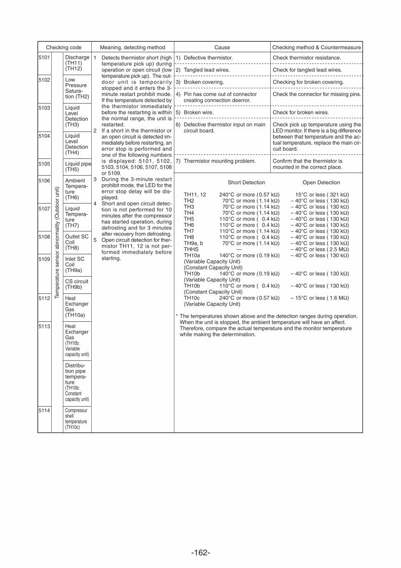
-162-
Discharge(TH11)(TH12)
LowPressureSatura-tion (TH2)
LiquidLevelDetection(TH3)
LiquidLevelDetection(TH4)
Liquid pipe(TH5)
AmbientTempera-ture(TH6)
LiquidTempera-ture(TH7)
Outlet SCCoil(TH8)
Inlet SCCoil(TH9a)
CS circuit(TH9b)
HeatExchangerGas(TH10a)
HeatExchangerGas(TH10b:Variablecapacity unit)
Distribu-tion pipetempera-ture(TH10b:Constantcapacity unit)
Compressurshelltemperature(TH10c)
Checking code Meaning, detecting method Cause Checking method & Countermeasure
5101
5102
5103
5104
5105
5106
5107
5108
5109
5112
5113
5114
1 Detects thermistor short (hightemperature pick up) duringoperation or open circuit (lowtemperature pick up). The out-door uni t is temporar i lystopped and it enters the 3-minute restart prohibit mode.If the temperature detected bythe thermistor immediatelybefore the restarting is withinthe normal range, the unit isrestarted.
2 If a short in the thermistor oran open circuit is detected im-mediately before restarting, anerror stop is performed andone of the following numbersis displayed: 5101, 5102,5103, 5104, 5106, 5107, 5108or 5109.
3 During the 3-minute restartprohibit mode, the LED for theerror stop delay will be dis-played.
4 Short and open circuit detec-tion is not performed for 10minutes after the compressorhas started operation, duringdefrosting and for 3 minutesafter recovery from defrosting.
5 Open circuit detection for ther-mistor TH11, 12 is not per-formed immediately beforestarting.
Check thermistor resistance.
Check for tangled lead wires.
Checking for broken covering.
Check the connector for missing pins.
Check for broken wires.
Check pick up temperature using theLED monitor. If there is a big differencebetween that temperature and the ac-tual temperature, replace the main cir-cuit board.
Confirm that the thermistor ismounted in the correct place.
1) Defective thermistor.
2) Tangled lead wires.
3) Broken covering.
4) Pin has come out of connectorcreating connection deerror.
5) Broken wire.
6) Defective thermistor input on maincircuit board.
7) Thermistor mounting problem.
Tem
pera
ture
sen
sor
abno
rmal
ity (
Out
door
uni
t)
Short Detection Open Detection
TH11, 12 240 C or more (0.57 k ) 15 C or less ( 321 k )TH2 70 C or more (1.14 k ) – 40 C or less ( 130 k )TH3 70 C or more (1.14 k ) – 40 C or less ( 130 k )TH4 70 C or more (1.14 k ) – 40 C or less ( 130 k )TH5 110 C or more ( 0.4 k ) – 40 C or less ( 130 k )TH6 110 C or more ( 0.4 k ) – 40 C or less ( 130 k )TH7 110 C or more (1.14 k ) – 40 C or less ( 130 k )TH8 110 C or more ( 0.4 k ) – 40 C or less ( 130 k )TH9a, b 70 C or more (1.14 k ) – 40 C or less ( 130 k )THHS — – 40 C or less ( 2.5 M )TH10a 140 C or more (0.19 k ) – 40 C or less ( 130 k )(Variable Capacity Unit)(Constant Capacity Unit)TH10b 140 C or more (0.19 k ) – 40 C or less ( 130 k )(Variable Capacity Unit)TH10b 110 C or more ( 0.4 k ) – 40 C or less ( 130 k )(Constant Capacity Unit)TH10c 240 C or more (0.57 k ) – 15 C or less ( 1.6 M )(Variable Capacity Unit)
* The temperatures shown above and the detection ranges during operation.When the unit is stopped, the ambient temperature will have an affect.Therefore, compare the actual temperature and the monitor temperaturewhile making the determination.
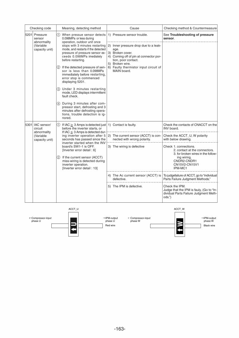
-163-
Checking code Meaning, detecting method Cause Checking method & Countermeasure
5201
5301
Pressuresensorabnormality(Variable capacity unit)
IAC sensor/circuitabnormality(Variable capacity unit)
When pressue sensor detectsor less during
stops with 3 minutes restartingmode, and restarts if the detectedpressure of pressure sensor ex-ceeds
If the detected pressure of sen-sor is less than immediately before restarting, error stop is commenced displaying 5201.
Under 3 minutes restartingmode, LED displays intermittentfault check.
During 3 minutes after com-pressor start, defrosting and 3minutes after defrosting opera-tions, trouble detection is ig-nored.
If IAC 3 Amps is detected justbefore the inverter starts, orIf IAC 3 Amps is detected dur-ing inverter operation after 5seconds has passed since theinverter started when the INVboard’s SW1-1 is OFF.[Inverter error detail : 6]
If the current sensor (ACCT)miss-wiring is detected duringinverter operation.[Inverter error detail : 13]
1)
2) Inner pressure drop due to a leak-age.
3) Broken cover.4) Coming off of pin at connector por-
tion, poor contact.5) Broken wire.6) Faulty thermistor input circuit of
MAIN board.
1) Contact is faulty.
2) The current sensor (ACCT) is con-nected with wrong polarity.
3) The wiring is defective
4) The Ac current sensor (ACCT) isdefective.
5) The IPM is defective.
See Troubleshooting of pressuresensor.
Check the contacts of CNACCT on theINV board.
Check the ACCT_U, W polaritywith below drawing.
Check 1. connections.2. contact at the connectors.3. for broken wires in the follow-
ing wiring.CNDR2-CNDR1CN15V2-CN15V1IPM-MC1
To judgefailure of ACCT, go to “individualParts Failure Judgment Methods.”
Check the IPM.Judge that the IPM is fauly, (Go to “In-dividual Parts Failure Judgment Meth-ods.”)
ACCT_U
U
ACCT_W
IPM-output phase U
IPM-output phase W
Compressor-input phase U
Compressor-input phase W
Red wire Black wireW
0.098MPa imediately before restarting.
0.098MPaoperation, outdoor unit once
0.098MPa
Pressure sensor trouble.1
2
3
4
1
2
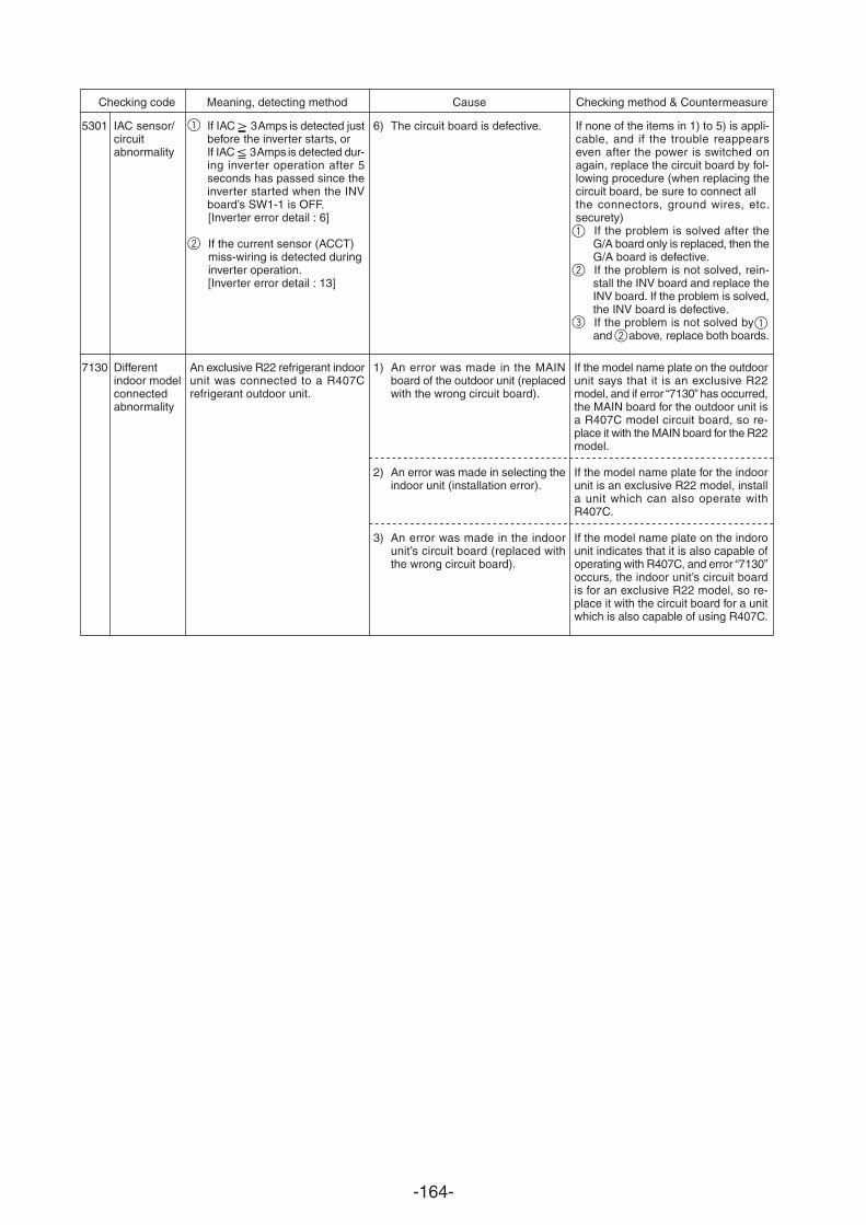
-164-
Checking code Meaning, detecting method Cause Checking method & Countermeasure
5301
Differentindoor modelconnectedabnormality
An exclusive R22 refrigerant indoorunit was connected to a R407Crefrigerant outdoor unit.
1) An error was made in the MAINboard of the outdoor unit (replacedwith the wrong circuit board).
2) An error was made in selecting theindoor unit (installation error).
3) An error was made in the indoorunit’s circuit board (replaced withthe wrong circuit board).
If the model name plate on the outdoorunit says that it is an exclusive R22model, and if error “7130” has occurred,the MAIN board for the outdoor unit isa R407C model circuit board, so re-place it with the MAIN board for the R22model.
If the model name plate for the indoorunit is an exclusive R22 model, installa unit which can also operate withR407C.
If the model name plate on the indorounit indicates that it is also capable ofoperating with R407C, and error “7130”occurs, the indoor unit’s circuit boardis for an exclusive R22 model, so re-place it with the circuit board for a unitwhich is also capable of using R407C.
If none of the items in 1) to 5) is appli-cable, and if the trouble reappearseven after the power is switched onagain, replace the circuit board by fol-lowing procedure (when replacing thecircuit board, be sure to connect allthe connectors, ground wires, etc.securety)
If the problem is solved after theG/A board only is replaced, then theG/A board is defective.If the problem is not solved, rein-stall the INV board and replace theINV board. If the problem is solved,the INV board is defective.If the problem is not solved by and above, replace both boards.
6) The circuit board is defective.
7130
IAC sensor/circuitabnormality
If IAC 3 is detected justbefore the inverter starts, orIf IAC 3 is detected dur-ing inverter operation after 5seconds has passed since theinverter started when the INVboard’s SW1-1 is OFF.[Inverter error detail : 6]
If the current sensor (ACCT)miss-wiring is detected duringinverter operation.[Inverter error detail : 13]
1
2
3
2
1
12
Amps
Amps
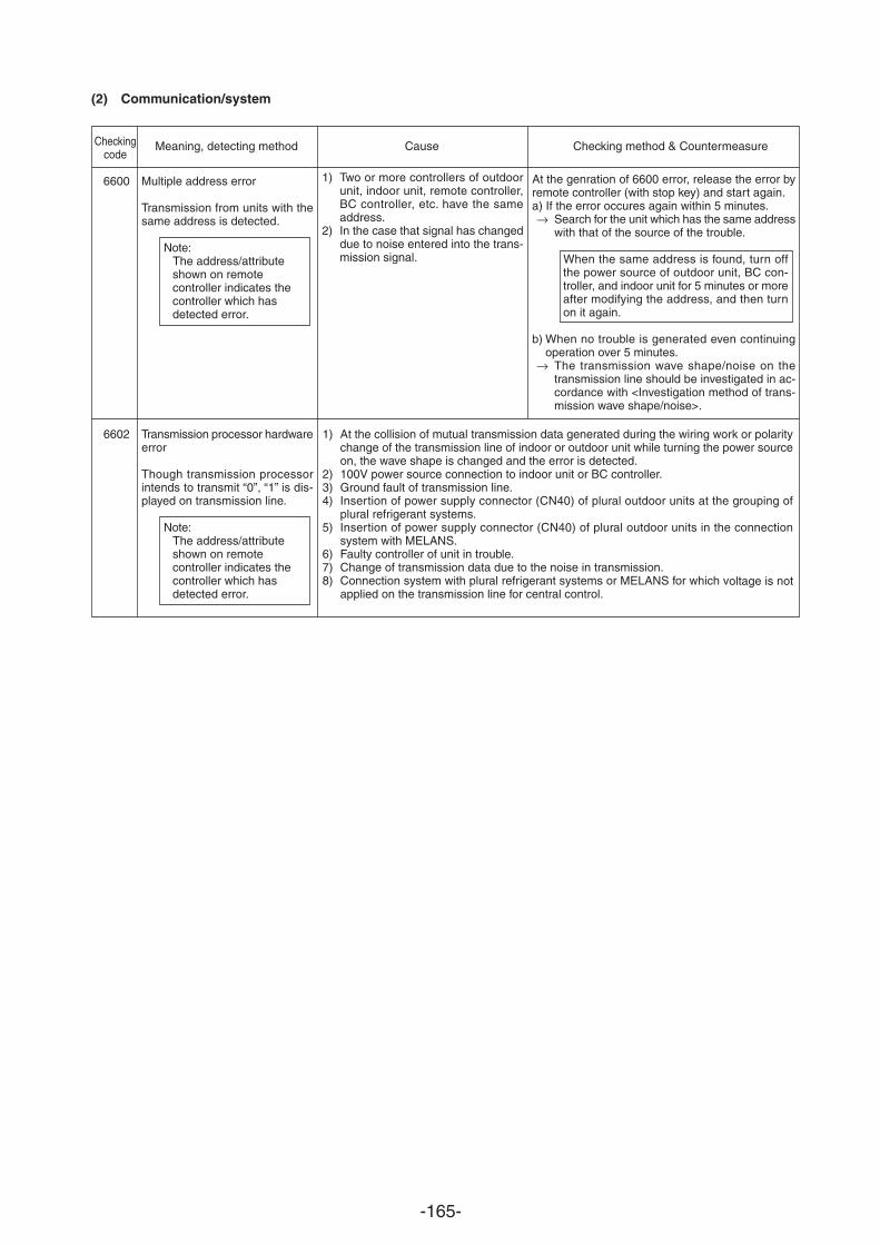
-165-
(2) Communication/system
Checkingcode
6600
6602
Multiple address error
Transmission from units with thesame address is detected.
Note:The address/attributeshown on remotecontroller indicates thecontroller which hasdetected error.
Transmission processor hardwareerror
Though transmission processorintends to transmit “0”, “1” is dis-played on transmission line.
Note:The address/attributeshown on remotecontroller indicates thecontroller which hasdetected error.
Meaning, detecting method Cause Checking method & Countermeasure
At the genration of 6600 error, release the error byremote controller (with stop key) and start again.a) If the error occures again within 5 minutes.
Search for the unit which has the same addresswith that of the source of the trouble.
When the same address is found, turn offthe power source of outdoor unit, BC con-troller, and indoor unit for 5 minutes or moreafter modifying the address, and then turnon it again.
b) When no trouble is generated even continuingoperation over 5 minutes.
The transmission wave shape/noise on thetransmission line should be investigated in ac-cordance with <Investigation method of trans-mission wave shape/noise>.
1) Two or more controllers of outdoorunit, indoor unit, remote controller,BC controller, etc. have the sameaddress.
2) In the case that signal has changeddue to noise entered into the trans-mission signal.
1) At the collision of mutual transmission data generated during the wiring work or polaritychange of the transmission line of indoor or outdoor unit while turning the power sourceon, the wave shape is changed and the error is detected.
2) 100V power source connection to indoor unit or BC controller.3) Ground fault of transmission line.4) Insertion of power supply connector (CN40) of plural outdoor units at the grouping of
plural refrigerant systems.5) Insertion of power supply connector (CN40) of plural outdoor units in the connection
system with MELANS.6) Faulty controller of unit in trouble.7) Change of transmission data due to the noise in transmission.8) Connection system with plural refrigerant systems or MELANS for which voltage is not
applied on the transmission line for central control.
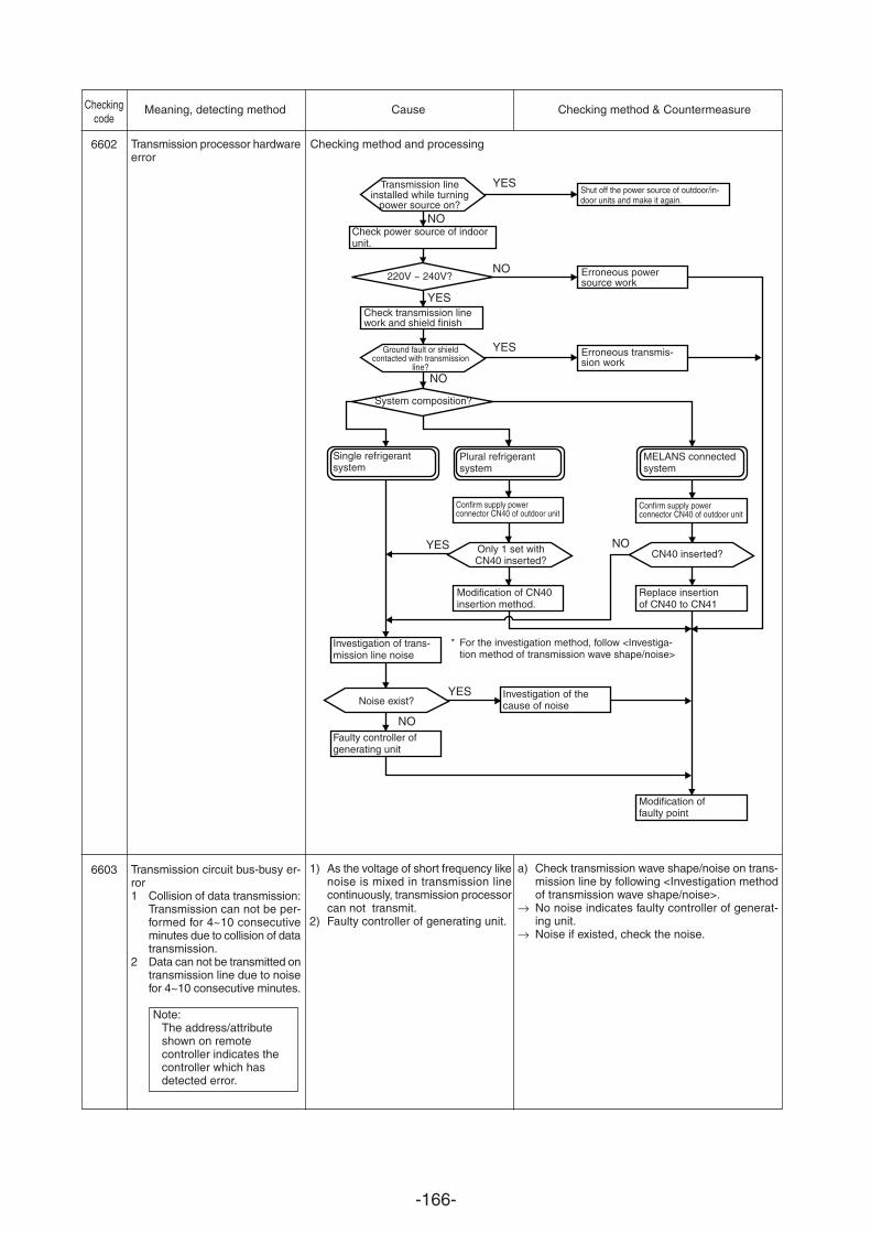
-166-
Transmission processor hardwareerror
Transmission circuit bus-busy er-ror1 Collision of data transmission:
Transmission can not be per-formed for 4~10 consecutiveminutes due to collision of datatransmission.
2 Data can not be transmitted ontransmission line due to noisefor 4~10 consecutive minutes.
Note:The address/attributeshown on remotecontroller indicates thecontroller which hasdetected error.
Checking method and processing
1) As the voltage of short frequency likenoise is mixed in transmission linecontinuously, transmission processorcan not transmit.
2) Faulty controller of generating unit.
a) Check transmission wave shape/noise on trans-mission line by following <Investigation methodof transmission wave shape/noise>.No noise indicates faulty controller of generat-ing unit.Noise if existed, check the noise.
Checkingcode
6602
6603
Meaning, detecting method Cause Checking method & Countermeasure
Transmission lineinstalled while turning
power source on?
Check power source of indoorunit.
220V ~ 240V?
Shut off the power source of outdoor/in-door units and make it again.
Erroneous powersource work
Erroneous transmis-sion work
Check transmission linework and shield finish
Ground fault or shieldcontacted with transmission
line?
System composition?
Single refrigerantsystem
Investigation of trans-mission line noise
Modification offaulty point
Replace insertionof CN40 to CN41
CN40 inserted?
Confirm supply powerconnector CN40 of outdoor unit
MELANS connectedsystem
Investigation of thecause of noise
* For the investigation method, follow <Investiga-tion method of transmission wave shape/noise>
Modification of CN40insertion method.
Only 1 set withCN40 inserted?
Noise exist?
Faulty controller ofgenerating unit
Plural refrigerantsystem
Confirm supply powerconnector CN40 of outdoor unit
NO
YES
YES
YES
NO
NO
YES NO
YES
NO
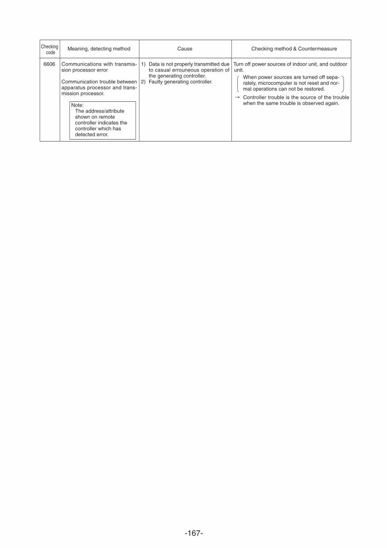
-167-
Checkingcode
6606
Meaning, detecting method Cause Checking method & Countermeasure
1) Data is not properly transmitted dueto casual errouneous operation ofthe generating controller.
2) Faulty generating controller.
Communications with transmis-sion processor error
Communication trouble betweenapparatus processor and trans-mission processor.
Note:The address/attributeshown on remotecontroller indicates thecontroller which hasdetected error.
Turn off power sources of indoor unit, and outdoor unit.
When power sources are turned off sepa-rately, microcomputer is not reset and nor-mal operations can not be restored.
Controller trouble is the source of the troublewhen the same trouble is observed again.
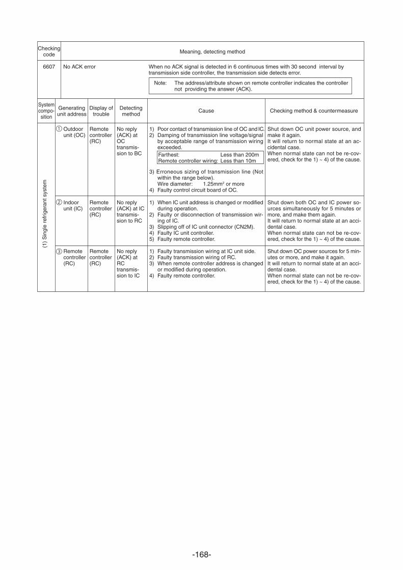
-168-
Checkingcode
6607
Meaning, detecting method
No ACK error When no ACK signal is detected in 6 continuous times with 30 second interval bytransmission side controller, the transmission side detects error.
Note: The address/attribute shown on remote controller indicates the controllernot providing the answer (ACK).
1 Outdoorunit (OC)
Indoorunit (IC)
Remotecontroller(RC)
(1)
Sin
gle
refr
iger
ant s
yste
m
Remotecontroller(RC)
Remotecontroller(RC)
Remotecontroller(RC)
Systemcompo-sition
Generatingunit address
Display oftrouble
Detectingmethod
Cause Checking method & countermeasure
No reply(ACK) atOCtransmis-sion to BC
No reply(ACK) at ICtransmis-sion to RC
No reply(ACK) atRCtransmis-sion to IC
1) Poor contact of transmission line of OC and IC.2) Damping of transmission line voltage/signal
by acceptable range of transmission wiringexceeded.Farthest: Less than 200mRemote controller wiring: Less than 10m
3) Erroneous sizing of transmission line (Notwithin the range below).Wire diameter: 1.25mm2 or more
4) Faulty control circuit board of OC.
1) When IC unit address is changed or modifiedduring operation.
2) Faulty or disconnection of transmission wir-ing of IC.
3) Slipping off of IC unit connector (CN2M).4) Faulty IC unit controller.5) Faulty remote controller.
1) Faulty transmission wiring at IC unit side.2) Faulty transmission wiring of RC.3) When remote controller address is changed
or modified during operation.4) Faulty remote controller.
Shut down OC unit power source, andmake it again.It will return to normal state at an ac-cidental case.When normal state can not be re-cov-ered, check for the 1) ~ 4) of the cause.
Shut down both OC and IC power so-urces simultaneously for 5 minutes ormore, and make them again.It will return to normal state at an acci-dental case.When normal state can not be re-cov-ered, check for the 1) ~ 4) of the cause.
Shut down OC power sources for 5 min-utes or more, and make it again.It will return to normal state at an acci-dental case.When normal state can not be re-cov-ered, check for the 1) ~ 4) of the cause.
2
3
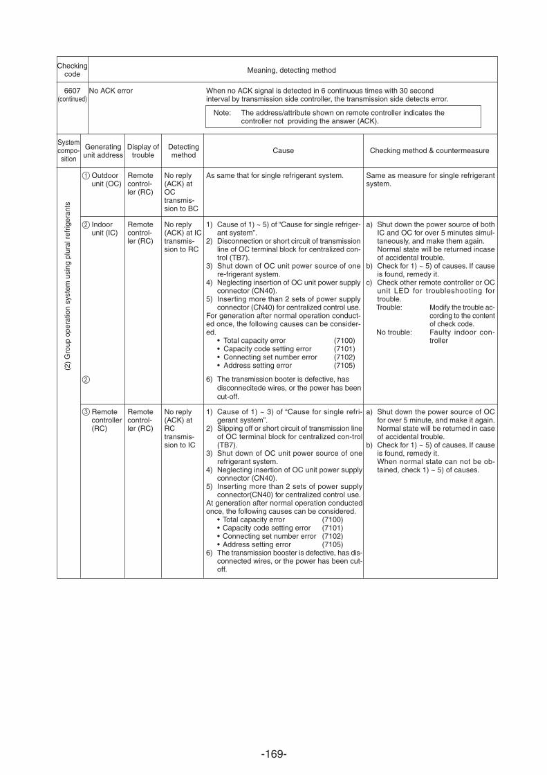
-169-
Checkingcode
6607(continued)
Meaning, detecting method
Systemcompo-sition
Generatingunit address
Display oftrouble
Detectingmethod
Cause Checking method & countermeasure
No ACK error When no ACK signal is detected in 6 continuous times with 30 secondinterval by transmission side controller, the transmission side detects error.
Note: The address/attribute shown on remote controller indicates thecontroller not providing the answer (ACK).
Outdoorunit (OC)
Indoorunit (IC)
Remotecontroller(RC)
Remotecontrol-ler (RC)
Remotecontrol-ler (RC)
Remotecontrol-ler (RC)
No reply(ACK) atOCtransmis-sion to BC
No reply(ACK) at ICtransmis-sion to RC
No reply(ACK) atRCtransmis-sion to IC
As same that for single refrigerant system.
1) Cause of 1) ~ 5) of “Cause for single refriger-ant system”.
2) Disconnection or short circuit of transmissionline of OC terminal block for centralized con-trol (TB7).
3) Shut down of OC unit power source of onere-frigerant system.
4) Neglecting
6) The transmission booter is defective, has disconnecitede wires, or the power has beencut-off.
insertion of OC unit power supplyconnector (CN40).
5) Inserting more than 2 sets of power supplyconnector (CN40) for centralized control use.
For generation after normal operation conduct-ed once, the following causes can be consider-ed.
• Total capacity error (7100)• Capacity code setting error (7101)• Connecting set number error (7102)• Address setting error (7105)
Same as measure for single refrigerantsystem.
a) Shut down the power source of bothIC and OC for over 5 minutes simul-taneously, and make them again.Normal state will be returned incaseof accidental trouble.
b) Check for 1) ~ 5) of causes. If causeis found, remedy it.
c) Check other remote controller or OCunit LED for troubleshooting fortrouble.Trouble: Modify the trouble ac-
cording to the contentof check code.
No trouble: Faulty indoor con-troller
a) Shut down the power source of OCfor over 5 minute, and make it again.Normal state will be returned in caseof accidental trouble.
b) Check for 1) ~ 5) of causes. If causeis found, remedy it.When normal state can not be ob-tained, check 1) ~ 5) of causes.
(2)
Gro
up o
pera
tion
syst
em u
sing
plu
ral r
efrig
eran
ts
1) Cause of 1) ~ 3) of “Cause for single refri-gerant system”.
2) Slipping off or short circuit of transmission lineof OC terminal block for centralized con-trol(TB7).
3) Shut down of OC unit power source of onerefrigerant system.
4) Neglecting insertion of OC unit power supplyconnector (CN40).
5) Inserting more than 2 sets of power supplyconnector(CN40) for centralized control use.
At generation after normal operation conductedonce, the following causes can be considered.
• Total capacity error (7100)• Capacity code setting error (7101)• Connecting set number error (7102)• Address setting error (7105)
6) The transmission booster is defective, has dis-connected wires, or the power has been cut-off.
1
2
2
3
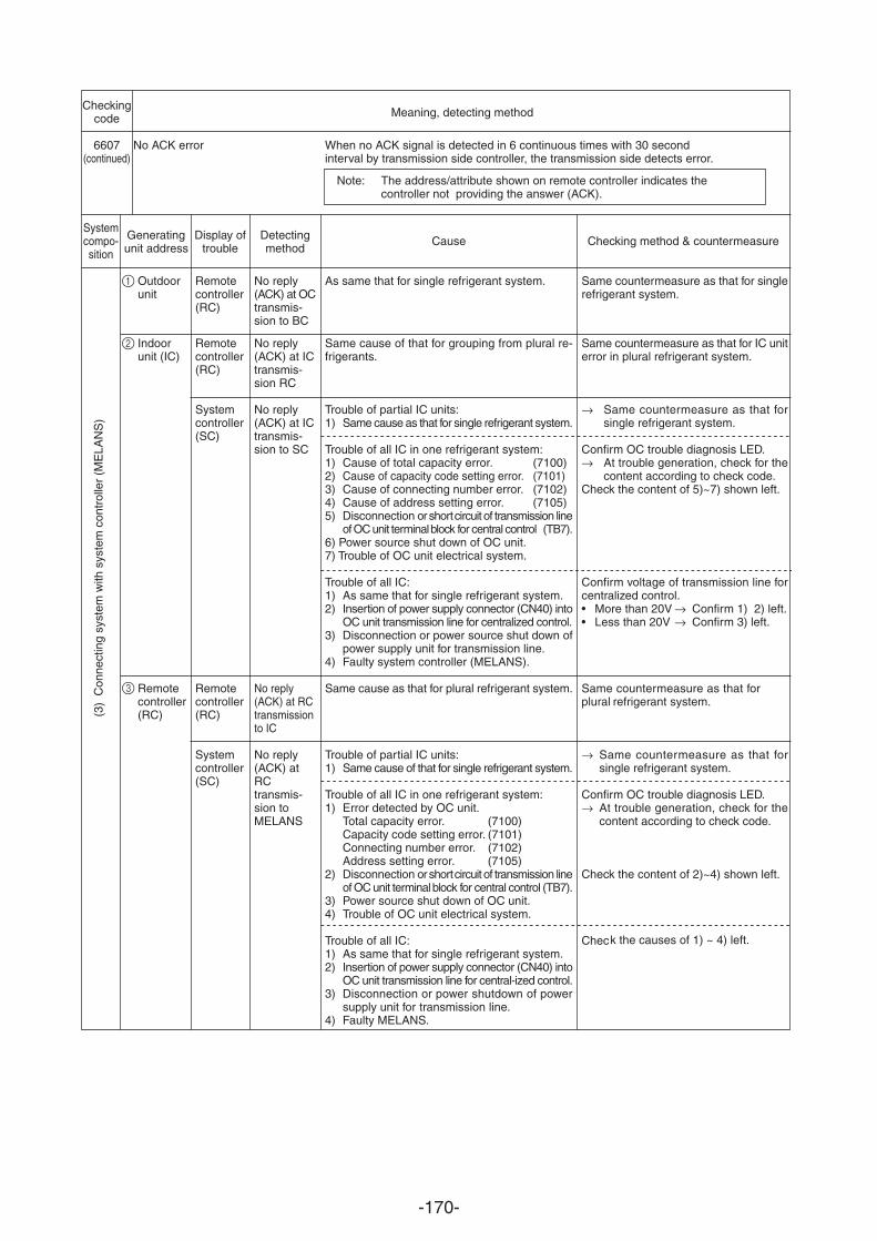
-170-
Checkingcode
6607(continued)
Meaning, detecting method
Systemcompo-sition
Generatingunit address
Display oftrouble
Detectingmethod
Cause Checking method & countermeasure
No ACK error When no ACK signal is detected in 6 continuous times with 30 secondinterval by transmission side controller, the transmission side detects error.
Note: The address/attribute shown on remote controller indicates thecontroller not providing the answer (ACK).
(3)
Con
nect
ing
syst
em w
ith s
yste
m c
ontr
olle
r (M
ELA
NS
)
Outdoorunit
Indoorunit (IC)
Remotecontroller(RC)
Remotecontroller(RC)
Remotecontroller(RC)
Systemcontroller(SC)
Remotecontroller(RC)
Systemcontroller(SC)
No reply(ACK) at OCtransmis-sion to BC
No reply(ACK) at ICtransmis-sion RC
No reply(ACK) at ICtransmis-sion to SC
No reply(ACK) at RCtransmissionto IC
No reply(ACK) atRCtransmis-sion toMELANS
As same that for single refrigerant system.
Same cause of that for grouping from plural re-frigerants.
Trouble of partial IC units:1) Same cause as that for single refrigerant system.
Trouble of all IC in one refrigerant system:1) Cause of total capacity error. (7100)2) Cause of capacity code setting error. (7101)3) Cause of connecting number error. (7102)4) Cause of address setting error. (7105)5) Disconnection or short circuit of transmission line
of OC unit terminal block for central control (TB7).6) Power source shut down of OC unit.7) Trouble of OC unit electrical system.
Trouble of all IC:1) As same that for single refrigerant system.2) Insertion of power supply connector (CN40) into
OC unit transmission line for centralized control.3) Disconnection or power source shut down of
power supply unit for transmission line.4) Faulty system controller (MELANS).
Same cause as that for plural refrigerant system.
Trouble of partial IC units:1) Same cause of that for single refrigerant system.
Trouble of all IC in one refrigerant system:1) Error detected by OC unit.
Total capacity error. (7100)Capacity code setting error. (7101)Connecting number error. (7102)Address setting error. (7105)
2) Disconnection or short circuit of transmission lineof OC unit terminal block for central control (TB7).
3) Power source shut down of OC unit.4) Trouble of OC unit electrical system.
Trouble of all IC:1) As same that for single refrigerant system.2) Insertion of power supply connector (CN40) into
OC unit transmission line for central-ized control.3) Disconnection or power shutdown of power
supply unit for transmission line.4) Faulty MELANS.
Same countermeasure as that for singlerefrigerant system.
Same countermeasure as that for IC uniterror in plural refrigerant system.
Same countermeasure as that forsingle refrigerant system.
Confirm OC trouble diagnosis LED.At trouble generation, check for thecontent according to check code.
Check the content of 5)~7) shown left.
Confirm voltage of transmission line forcentralized control.• More than 20V Confirm 1) 2) left.• Less than 20V Confirm 3) left.
Same countermeasure as that for plural refrigerant system.
Same countermeasure as that forsingle refrigerant system.
Confirm OC trouble diagnosis LED.At trouble generation, check for thecontent according to check code.
Check the content of 2)~4) shown left.
Check the causes of 1) ~ 4) left.
1
2
3
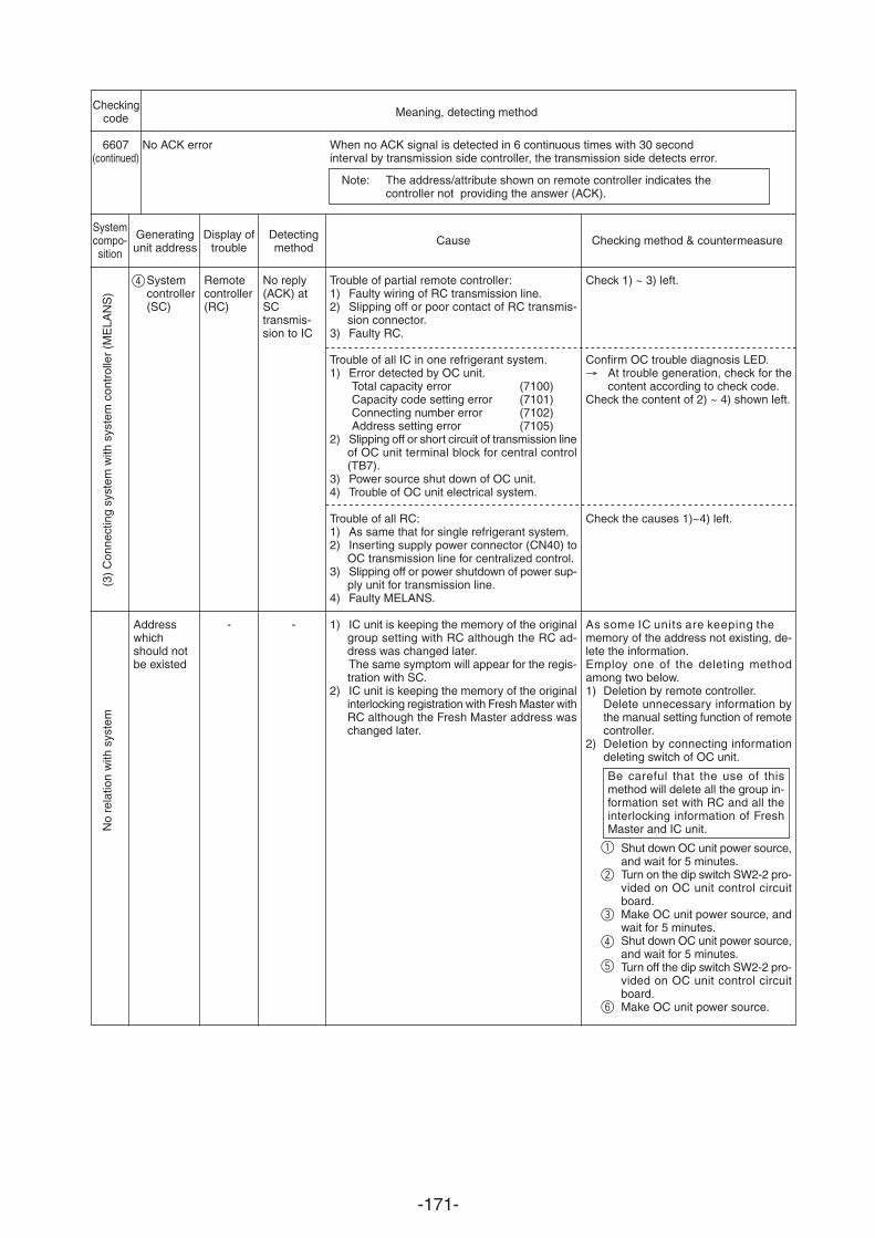
-171-
Checkingcode
6607(continued)
Meaning, detecting method
Systemcompo-sition
Generatingunit address
Display oftrouble
Detectingmethod
Cause Checking method & countermeasure
No ACK error When no ACK signal is detected in 6 continuous times with 30 secondinterval by transmission side controller, the transmission side detects error.
Note: The address/attribute shown on remote controller indicates thecontroller not providing the answer (ACK).
(3)
Con
nect
ing
syst
em w
ith s
yste
m c
ontr
olle
r (M
ELA
NS
)
Systemcontroller(SC)
Addresswhichshould notbe existed
Remotecontroller(RC)
-
Trouble of partial remote controller:1) Faulty wiring of RC transmission line.2) Slipping off or poor contact of RC transmis-
sion connector.3) Faulty RC.
Trouble of all IC in one refrigerant system.1) Error detected by OC unit.
Total capacity error (7100)Capacity code setting error (7101)Connecting number error (7102)Address setting error (7105)
2) Slipping off or short circuit of transmission lineof OC unit terminal block for central control(TB7).
3) Power source shut down of OC unit.4) Trouble of OC unit electrical system.
Trouble of all RC:1) As same that for single refrigerant system.2) Inserting supply power connector (CN40) to
OC transmission line for centralized control.3) Slipping off or power shutdown of power sup-
ply unit for transmission line.4) Faulty MELANS.
1) IC unit is keeping the memory of the originalgroup setting with RC although the RC ad-dress was changed later.The same symptom will appear for the regis-tration with SC.
2) IC unit is keeping the memory of the originalinterlocking registration with Fresh Master withRC although the Fresh Master address waschanged later.
No reply(ACK) atSCtransmis-sion to IC
-
Check 1) ~ 3) left.
Confirm OC trouble diagnosis LED.At trouble generation, check for thecontent according to check code.
Check the content of 2) ~ 4) shown left.
Check the causes 1)~4) left.
As some IC units are keeping thememory of the address not existing, de-lete the information.Employ one of the deleting methodamong two below.1) Deletion by remote controller.
Delete unnecessary information bythe manual setting function of remotecontroller.
2) Deletion by connecting informationdeleting switch of OC unit.
Be careful that the use of thismethod will delete all the group in-formation set with RC and all theinterlocking information of FreshMaster and IC unit.
1
2
3
4
5
6
Shut down OC unit power source,and wait for 5 minutes.Turn on the dip switch SW2-2 pro-vided on OC unit control circuitboard.Make OC unit power source, andwait for 5 minutes.Shut down OC unit power source,and wait for 5 minutes.Turn off the dip switch SW2-2 pro-vided on OC unit control circuitboard.Make OC unit power source.
No
rela
tion
with
sys
tem
4
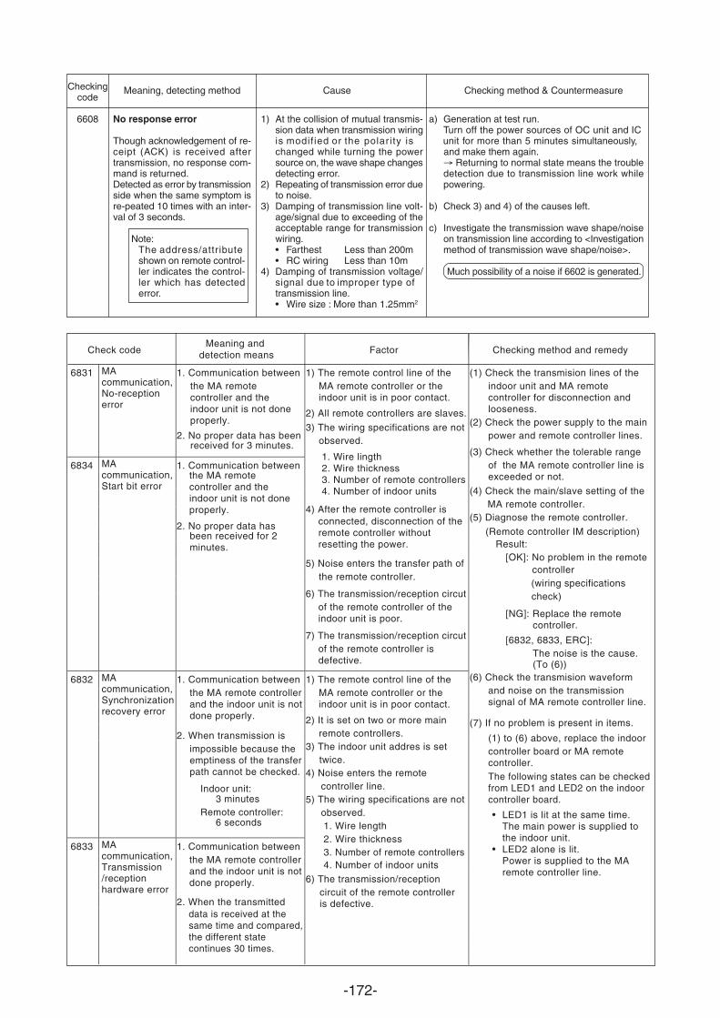
-172-
Checkingcode
6608
Meaning, detecting method Cause Checking method & Countermeasure
No response error
Though acknowledgement of re-ceipt (ACK) is received aftertransmission, no response com-mand is returned.Detected as error by transmissionside when the same symptom isre-peated 10 times with an inter-val of 3 seconds.
Note:The address/attr ibuteshown on remote control-ler indicates the control-ler which has detectederror.
1) At the collision of mutual transmis-sion data when transmission wiringis modified or the polar ity ischanged while turning the powersource on, the wave shape changesdetecting error.
2) Repeating of transmission error dueto noise.
3) Damping of transmission line volt-age/signal due to exceeding of theacceptable range for transmissionwiring.• Farthest Less than 200m• RC wiring Less than 10m
4) Damping of transmission voltage/signal due to improper type oftransmission line.• Wire size : More than 1.25mm2
a) Generation at test run.Turn off the power sources of OC unit unit for more than 5 minutes simultaneously,and make them again.
Returning to normal state means the troubledetection due to transmission line work whilepowering.
b) Check 3) and 4) of the causes left.
c) Investigate the transmission wave shape/noiseon transmission line according to <Investigationmethod of transmission wave shape/noise>.
Much possibility of a noise if 6602 is generated.
and IC
Check code Checking method and remedy
6831 MAcommunication,No-receptionerror
1. Communication between
2. No proper data has beenreceived for 3 minutes.
6834 MAcommunication,Start bit error
1. Communication between
2. No proper data has
1) The remote control line of the MA remote controller or the indoor unit is in poor contact.
2) All remote controllers are slaves.
3) The wiring specifications are notobserved.
1. Wire lingth2. Wire thickness3. Number of remote controllers4. Number of indoor units
4) After the remote controller is connected, disconnection of theremote controller without resetting the power.
5) Noise enters the transfer path ofthe remote controller.
6) The transmission/reception circutof the remote controller of the indoor unit is poor.
7) The transmission/reception circutof the remote controller is defective.
6832 MAcommunication,Synchronizationrecovery error
1. Communication between
6833 MA communication,Transmission/reception
1. Communication between
2. When the transmitted
1) The remote control line of the MA remote controller or the indoor unit is in poor contact.
2) It is set on two or more main remote controllers.
3) The indoor unit addres is set twice.
4) Noise enters the remotecontroller line.
5) The wiring specifications are notobserved.1. Wire length2. Wire thickness3. Number of remote controllers4. Number of indoor units
6) The transmission/receptioncircuit of the remote controller is defective.
(1) Check the transmision lines of the
(2) Check the power supply to the main power and remote controller lines.
(3) Check whether the tolerable range
(4) Check the main/slave setting of theMA remote controller.
(5) Diagnose the remote controller.
Result:
(wiring specificationscheck)
[6832, 6833, ERC]: The noise is the cause.
(6) Check the transmision waveform
(7) If no problem is present in items.
(1) to (6) above, replace the indoor controller board or MA remote controller.The following states can be checkedfrom LED1 and LED2 on the indoor controller board.
LED1 is lit at the same time. The main power is supplied to the indoor unit. LED2 alone is lit. Power is supplied to the MA remote controller line.
controller
(To (6))
and noise on the transmission signal of MA remote controller line.
FactorMeaning and
detection means
hardware error
the MA remote controller and the indoor unit is not doneproperly.
the MA remote controller and the indoor unit is not doneproperly.
been received for 2minutes.
the MA remote controller and the indoor unit is notdone properly.
2. When transmission isimpossible because the emptiness of the transfer path cannot be checked.
Indoor unit:3 minutes
Remote controller:6 seconds
the MA remote controllerand the indoor unit is notdone properly.
data is received at the same time and compared,the different state continues 30 times.
indoor unit and MA remote controller for disconnection and looseness.
of the MA remote controller line is exceeded or not.
(Remote controller IM description)
[OK]: No problem in the remote
[NG]: Replace the remotecontroller.
•
•
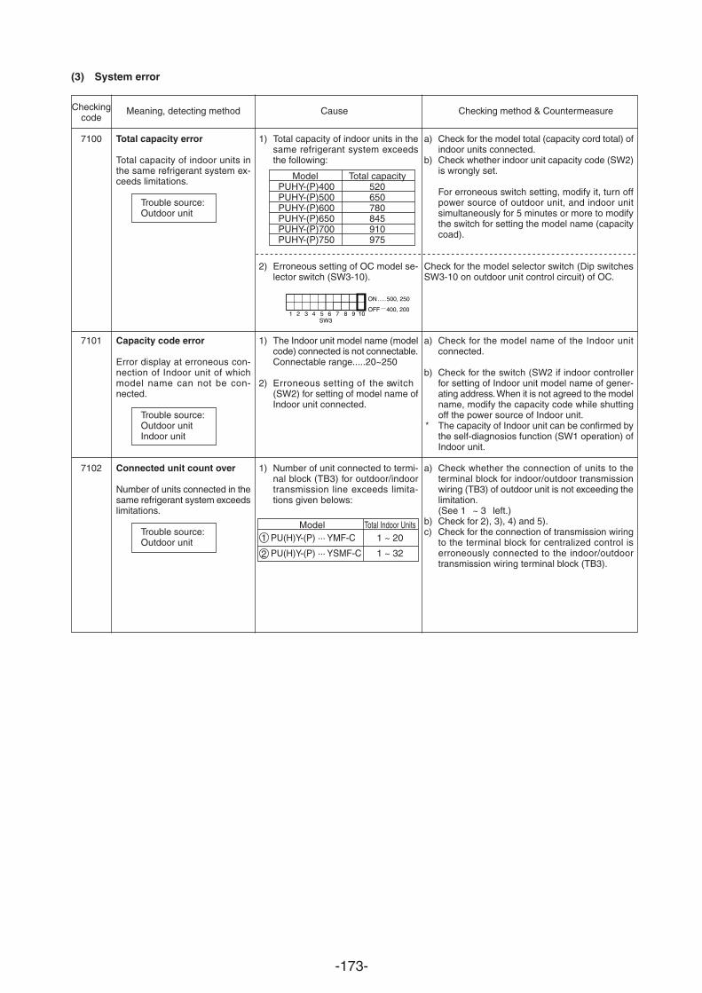
-173-
1) Total capacity of indoor units in thesame refrigerant system exceedsthe following:
2) Erroneous setting of OC model se-lector switch (SW3-10).
1) The Indoor unit model name (modelcode) connected is not connectable.Connectable range.....20~250
2) Erroneous setting of the switch(SW2) for setting of model name ofIndoor unit connected.
1) Number of unit connected to termi-nal block (TB3) for outdoor/indoortransmission line exceeds limita-tions given belows:
(3) System error
Checkingcode
7100
7101
7102
Meaning, detecting method Cause Checking method & Countermeasure
Total capacity error
Total capacity of indoor units inthe same refrigerant system ex-ceeds limitations.
Trouble source:Outdoor unit
Capacity code error
Error display at erroneous con-nection of Indoor unit of whichmodel name can not be con-nected.
Trouble source:Outdoor unitIndoor unit
Connected unit count over
Number of units connected in thesame refrigerant system exceedslimitations.
Trouble source:Outdoor unit
a) Check for the model total (capacity cord total) ofindoor units connected.
b) Check whether indoor unit capacity code (SW2)is wrongly set.
For erroneous switch setting, modify it, turn offpower source of outdoor unit, and indoor unitsimultaneously for 5 minutes or more to modifythe switch for setting the model name (capacitycoad).
Check for the model selector switch (Dip switchesSW3-10 on outdoor unit control circuit) of OC.
a) Check for the model name of the Indoor unitconnected.
b) Check for the switch (SW2 if indoor controllerfor setting of Indoor unit model name of gener-ating address. When it is not agreed to the modelname, modify the capacity code while shuttingoff the power source of Indoor unit.
* The capacity of Indoor unit can be confirmed bythe self-diagnosios function (SW1 operation) ofIndoor unit.
a) Check whether the connection of units to theterminal block for indoor/outdoor transmissionwiring (TB3) of outdoor unit is not exceeding thelimitation.(See 1 ~ 3 left.)
b) Check for 2), 3), 4) and 5).c) Check for the connection of transmission wiring
to the terminal block for centralized control iserroneously connected to the indoor/outdoortransmission wiring terminal block (TB3).
1
ON 500, 250
OFF 400, 2002 3 4 5
SW36 7 8 9 10
........
Model Total capacityPUHY-(P)400 520PUHY-(P)500 650PUHY-(P)600 780PUHY-(P)650 845PUHY-(P)700 910PUHY-(P)750 975
Model Total Indoor Units1 PU(H)Y-(P) ··· YMF-C 1 ~ 20
PU(H)Y-(P) ··· YSMF-C 1 ~ 322
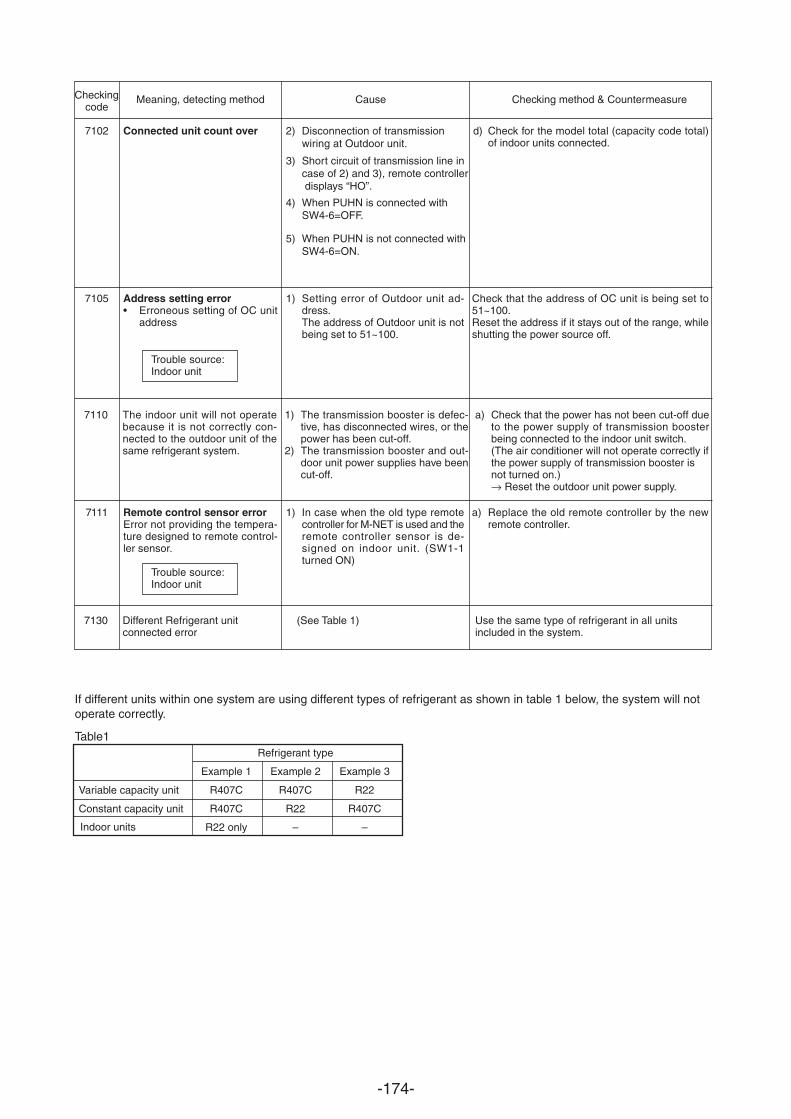
-174-
Checkingcode
7102
7105
7111
Meaning, detecting method Cause Checking method & Countermeasure
Connected unit count over
Address setting error• Erroneous setting of OC unit
address
Remote control sensor errorError not providing the tempera-ture designed to remote control-ler sensor.
Trouble source:Indoor unit
2) Disconnection of transmission wiring at Outdoor unit.
3) Short circuit of transmission line in case of 2) and 3), remote controller displays “HO”.
4) When PUHN is connected with SW4-6=OFF.
5) When PUHN is not connected withSW4-6=ON.
1) Setting error of Outdoor unit ad-dress.The address of Outdoor unit is notbeing set to 51~100.
1) In case when the old type remotecontroller for M-NET is used and theremote controller sensor is de-signed on indoor unit. (SW1-1turned ON)
d) Check for the model total (capacity code total)of indoor units connected.
Check that the address of OC unit is being set to51~100.Reset the address if it stays out of the range, whileshutting the power source off.
a) Replace the old remote controller by the newremote controller.
Trouble source:Indoor unit
a) Check that the power has not been cut-off dueto the power supply of transmission boosterbeing connected to the indoor unit switch.(The air conditioner will not operate correctly ifthe power supply of transmission booster isnot turned on.)→ Reset the outdoor unit power supply.
The indoor unit will not operatebecause it is not correctly con-nected to the outdoor unit of thesame refrigerant system.
1) The transmission booster is defec-tive, has disconnected wires, or thepower has been cut-off.
2) The transmission booster and out-door unit power supplies have beencut-off.
7110
Use the same type of refrigerant in all unitsincluded in the system.
Different Refrigerant unitconnected error
(See Table 1)7130
If different units within one system are using different types of refrigerant as shown in table 1 below, the system will notoperate correctly.
Table1Refrigerant type
Example 1 Example 2 Example 3
R407C R407C R22
R407C R22 R407C
R22 only – –
Variable capacity unit
Constant capacity unit
Indoor units
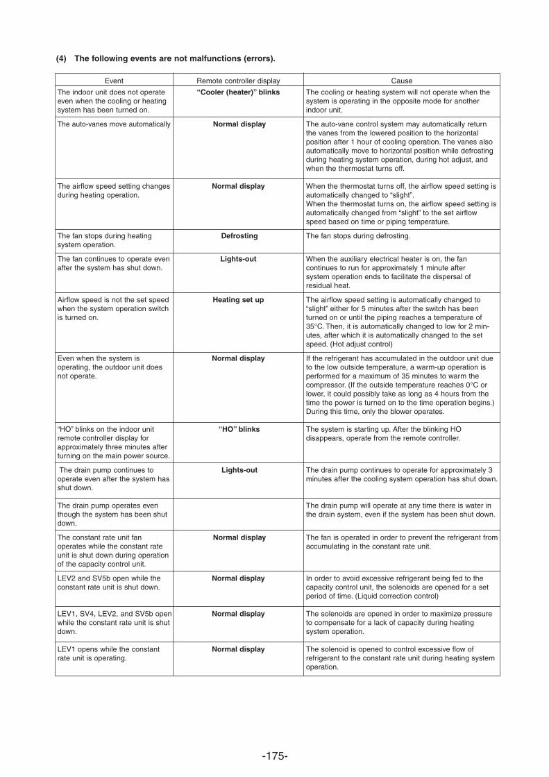
-175-
(4) The following events are not malfunctions (errors).
Event Remote controller display Cause
The indoor unit does not operateeven when the cooling or heatingsystem has been turned on.
The auto-vanes move automatically
The airflow speed setting changesduring heating operation.
The fan stops during heating system operation.
The fan continues to operate evenafter the system has shut down.
Airflow speed is not the set speedwhen the system operation switchis turned on.
Even when the system is operating, the outdoor unit doesnot operate.
“HO” blinks on the indoor unitremote controller display forapproximately three minutes afterturning on the main power source.
The drain pump continues to operate even after the system hasshut down.
The drain pump operates eventhough the system has been shutdown.
The constant rate unit fan operates while the constant rateunit is shut down during operationof the capacity control unit.
LEV2 and SV5b open while theconstant rate unit is shut down.
LEV1, SV4, LEV2, and SV5b openwhile the constant rate unit is shutdown.
LEV1 opens while the constantrate unit is operating.
“Cooler (heater)” blinks
Normal display
Normal display
Defrosting
Lights-out
Heating set up
Normal display
“HO” blinks
Lights-out
Normal display
Normal display
Normal display
Normal display
The cooling or heating system will not operate when thesystem is operating in the opposite mode for anotherindoor unit.
The auto-vane control system may automatically returnthe vanes from the lowered position to the horizontal position after 1 hour of cooling operation. The vanes alsoautomatically move to horizontal position while defrostingduring heating system operation, during hot adjust, andwhen the thermostat turns off.
When the thermostat turns off, the airflow speed setting isautomatically changed to “slight”.When the thermostat turns on, the airflow speed setting isautomatically changed from “slight” to the set airflowspeed based on time or piping temperature.
The fan stops during defrosting.
When the auxiliary electrical heater is on, the fan continues to run for approximately 1 minute after system operation ends to facilitate the dispersal of residual heat.
The airflow speed setting is automatically changed to“slight” either for 5 minutes after the switch has beenturned on or until the piping reaches a temperature of35°C. Then, it is automatically changed to low for 2 min-utes, after which it is automatically changed to the setspeed. (Hot adjust control)
If the refrigerant has accumulated in the outdoor unit dueto the low outside temperature, a warm-up operation isperformed for a maximum of 35 minutes to warm the compressor. (If the outside temperature reaches 0°C orlower, it could possibly take as long as 4 hours from thetime the power is turned on to the time operation begins.)During this time, only the blower operates.
The system is starting up. After the blinking HO disappears, operate from the remote controller.
The drain pump continues to operate for approximately 3minutes after the cooling system operation has shut down.
The drain pump will operate at any time there is water inthe drain system, even if the system has been shut down.
The fan is operated in order to prevent the refrigerant fromaccumulating in the constant rate unit.
In order to avoid excessive refrigerant being fed to thecapacity control unit, the solenoids are opened for a setperiod of time. (Liquid correction control)
The solenoids are opened in order to maximize pressureto compensate for a lack of capacity during heating system operation.
The solenoid is opened to control excessive flow of refrigerant to the constant rate unit during heating systemoperation.
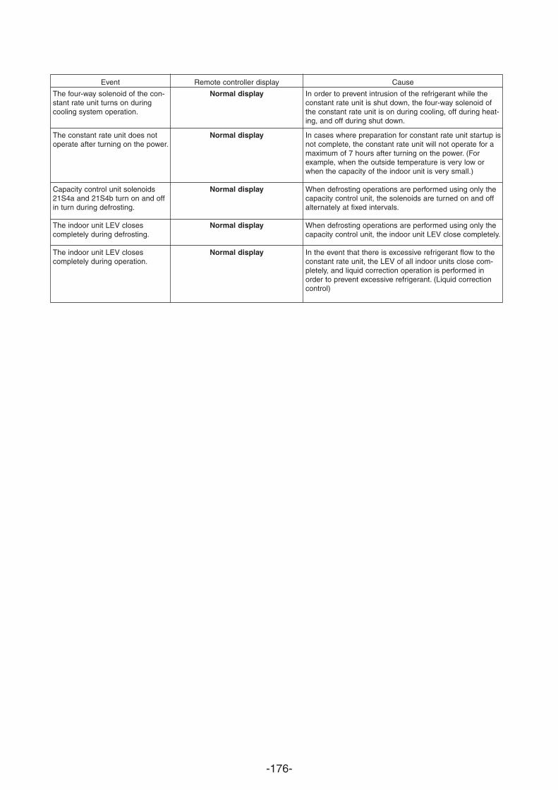
-176-
Event Remote controller display Cause
The four-way solenoid of the con-stant rate unit turns on duringcooling system operation.
The constant rate unit does notoperate after turning on the power.
Capacity control unit solenoids21S4a and 21S4b turn on and offin turn during defrosting.
The indoor unit LEV closes completely during defrosting.
The indoor unit LEV closes completely during operation.
Normal display
Normal display
Normal display
Normal display
Normal display
In order to prevent intrusion of the refrigerant while theconstant rate unit is shut down, the four-way solenoid ofthe constant rate unit is on during cooling, off during heat-ing, and off during shut down.
In cases where preparation for constant rate unit startup isnot complete, the constant rate unit will not operate for amaximum of 7 hours after turning on the power. (Forexample, when the outside temperature is very low orwhen the capacity of the indoor unit is very small.)
When defrosting operations are performed using only thecapacity control unit, the solenoids are turned on and offalternately at fixed intervals.
When defrosting operations are performed using only thecapacity control unit, the indoor unit LEV close completely.
In the event that there is excessive refrigerant flow to theconstant rate unit, the LEV of all indoor units close com-pletely, and liquid correction operation is performed inorder to prevent excessive refrigerant. (Liquid correctioncontrol)
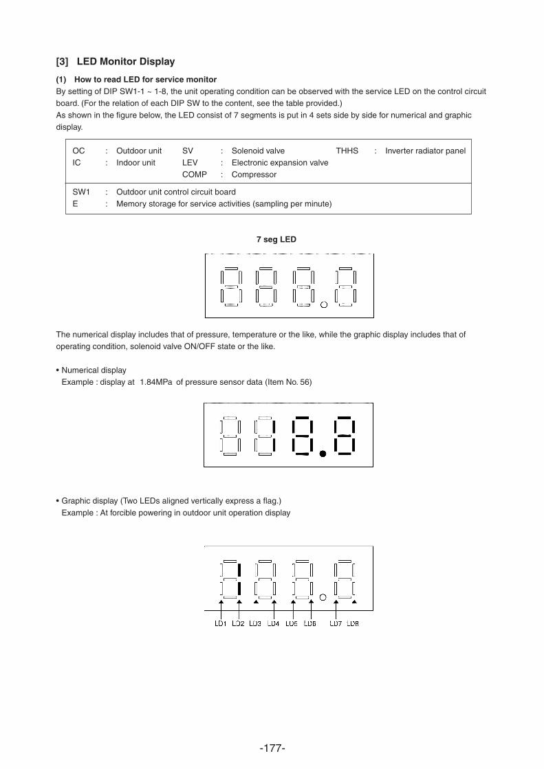
-177-
[3] LED Monitor Display
(1) How to read LED for service monitorBy setting of DIP SW1-1 ~ 1-8, the unit operating condition can be observed with the service LED on the control circuitboard. (For the relation of each DIP SW to the content, see the table provided.)
As shown in the figure below, the LED consist of 7 segments is put in 4 sets side by side for numerical and graphicdisplay.
OC : Outdoor unit SV : Solenoid valve THHS : Inverter radiator panelIC : Indoor unit LEV : Electronic expansion valve
COMP : Compressor
SW1 : Outdoor unit control circuit boardE : Memory storage for service activities (sampling per minute)
7 seg LED
The numerical display includes that of pressure, temperature or the like, while the graphic display includes that ofoperating condition, solenoid valve ON/OFF state or the like.
• Numerical displayExample : display at 1.84MPa of pressure sensor data (Item No. 56)
• Graphic display (Two LEDs aligned vertically express a flag.)
Example : At forcible powering in outdoor unit operation display
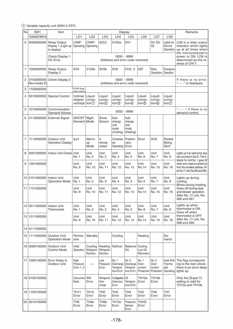
-178-
No SW1 Item Display Remarks
12345678910 LD1 LD2 LD3 LD4 LD5 LD6 LD7 LD8
0
1
2
3
4
5
6
7
8
9
10
11
12
13
14
15
16
17
18
19
20
0000000000
1000000000
0100000000(Also includes IC)
1100000000
0010000000
1010000000
0110000000
1110000000
0001000000
1001000000
0101000000
1101000000
0011000000
1011000000
0111000000
1111000000
0000100000
1000100000
0100100000
1100100000
0010100000
Relay Output
Check Display 1OC Error
Relay OutputDisplay 2
Check Display 2
Special Control
CommunicationDemand Volume
External Signal
Outdoor UnitOperation Display
Indoor Unit Check
Indoor UnitOperation Mode
Indoor UnitThermostat
Outdoor UnitOperation Mode
Outdoor UnitControl Mode
Error Delay inOutdoor Unit
COMPOperating
SV4
Confir
PUHN 4way valve control.
medrefrigerantovercharge
ON/OFFDemand
UnitNo. 1
UnitNo. 9
UnitNo. 1
UnitNo. 9
UnitNo. 1
UnitNo. 9
Permis-sion
InitialOperation
HighPressureError 1, 2
OvercurrentBreak
TH11Error
TH8Error
COMP1Operating
21S4b
Liquidcorrec-tion 1
NightMode
Warm-upMode
UnitNo. 2
UnitNo. 10
UnitNo. 2
UnitNo. 10
UnitNo. 2
UnitNo. 10
Standby
CoolingRefrigerantRecovery
—
INVError
TH12Error
TH9aError
52C2
SV5b
Liquidcorrec-tion 2
SnowSensor
3-minute,restart
UnitNo. 3
UnitNo. 11
UnitNo. 3
UnitNo. 11
UnitNo. 3
UnitNo. 11
HeatingRefrigerantRecovery
LowPressureError
RefrigerantOver-charge
TH2Error
TH9bError
21S4a
SV6
Liquidcorrec-tion 3
Autochangeovermode(Cooling)
Compres-sorOperating
UnitNo. 4
UnitNo. 12
UnitNo. 4
UnitNo. 12
UnitNo. 4
UnitNo. 12
Cooling
Defrost
No. 1DischargeTempera-ture Error
ConfigrationDetectionError
TH3Error
TH10cError
SV1
CH2, 3
Liquidcorrec-tion 4
Autochangeovermode(Heating)
Prelimi-naryError
UnitNo. 5
UnitNo. 13
UnitNo. 5
UnitNo. 13
UnitNo. 5
UnitNo. 13
BalanceOil
No. 2DischargeTempera-ture Error
OilTempera-ture Error
TH4Error
PressureSensorError
52F
Liquidcorrec-tion 5
Error
UnitNo. 6
UnitNo.14
UnitNo. 6
UnitNo.14
UnitNo. 6
UnitNo.14
Heating
CoolingLow OilRecovery
No. 1Over-currentProtection
TH10aError
TH5Error
THHSError
SV 22/32
RetryOperation
Liquidcorrec-tion 6
UnitNo. 7
UnitNo. 15
UnitNo. 7
UnitNo. 15
UnitNo. 7
UnitNo. 15
No. 2Over-currentProtection
TH10bError
TH6Error
Lights forNormalOperation
EmergencyOperation
Liquidcorrec-tion 7
PacketBeingSent
UnitNo. 8
UnitNo. 16
UnitNo. 8
UnitNo. 16
UnitNo. 8
UnitNo. 16
De-mand
Heat SinkThermo-statOperating
TH7Error
LD8 is a relay outputindicator which lightsup at all times whenthe microcomputer’spower is ON. LD8 isdetermined as the re-verse of CH11.
If there is no error,“- - - -” is displayed.
“- - - -” if there is nodemand control.
Lights up if an abnormal stophas occurred in the IC. The in-dicator for Unit No. 1 goes offwhen error reset is carried outfrom the smallest address. Af-ter No.17 unit, No.264 and 265.
Lights up duringcooling.Blinks during heating.Goes off during stopand blower operation.After No. 17 unit, No.266 and 267.
Lights up whenthermostat is ON.Goes off whenthermostat is OFF.After No. 17 unit, No.268 and 269.
The flag correspond-ing to the item wherethere is an error delaylights up.
Only the [Super Y]setting is valid forTH10a and TH10b.
0000 ~ 9999(Address and error code reversed)
0000 ~ 9999(Address and error code reversed)
1 Variable capacity unit (SW4-2 OFF)
0000 ~ 9999
Display 1 (Light upto display)
SV7 SV8
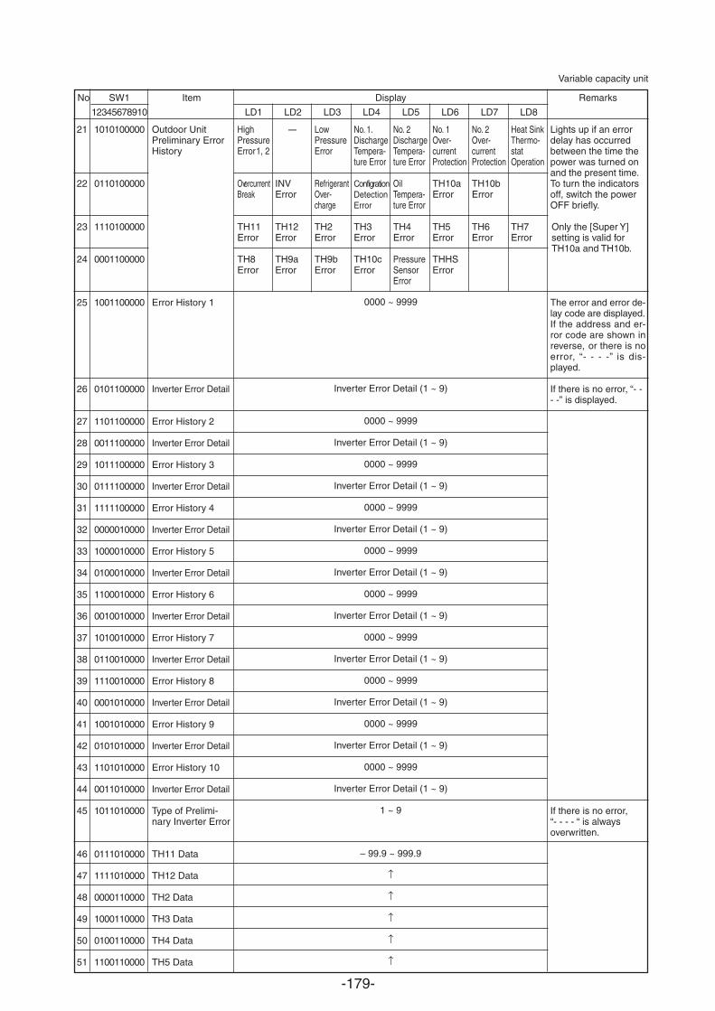
-179-
No SW1 Item Display Remarks
12345678910 LD1 LD2 LD3 LD4 LD5 LD6 LD7 LD8
21
22
23
24
25
26
27
28
29
30
31
32
33
34
35
36
37
38
39
40
41
42
43
44
45
46
47
48
49
50
51
1010100000
0110100000
1110100000
0001100000
1001100000
0101100000
1101100000
0011100000
1011100000
0111100000
1111100000
0000010000
1000010000
0100010000
1100010000
0010010000
1010010000
0110010000
1110010000
0001010000
1001010000
0101010000
1101010000
0011010000
1011010000
0111010000
1111010000
0000110000
1000110000
0100110000
1100110000
Outdoor UnitPreliminary ErrorHistory
Error History 1
Inverter Error Detail
Error History 2
Inverter Error Detail
Error History 3
Inverter Error Detail
Error History 4
Inverter Error Detail
Error History 5
Inverter Error Detail
Error History 6
Inverter Error Detail
Error History 7
Inverter Error Detail
Error History 8
Inverter Error Detail
Error History 9
Inverter Error Detail
Error History 10
Inverter Error Detail
Type of Prelimi-nary Inverter Error
TH11 Data
TH12 Data
TH2 Data
TH3 Data
TH4 Data
TH5 Data
HighPressureError 1, 2
OvercurrentBreak
TH11Error
TH8Error
—
INVError
TH12Error
TH9aError
LowPressureError
RefrigerantOver-charge
TH2Error
TH9bError
No. 1.DischargeTempera-ture Error
ConfigrationDetectionError
TH3Error
TH10cError
No. 2DischargeTempera-ture Error
OilTempera-ture Error
TH4Error
PressureSensorError
No. 2Over-currentProtection
TH10bError
TH6Error
Heat SinkThermo-statOperation
TH7Error
No. 1Over-currentProtection
TH10aError
TH5Error
THHSError
0000 ~ 9999
Inverter Error Detail (1 ~ 9)
0000 ~ 9999
Inverter Error Detail (1 ~ 9)
0000 ~ 9999
Inverter Error Detail (1 ~ 9)
0000 ~ 9999
Inverter Error Detail (1 ~ 9)
0000 ~ 9999
Inverter Error Detail (1 ~ 9)
0000 ~ 9999
Inverter Error Detail (1 ~ 9)
0000 ~ 9999
Inverter Error Detail (1 ~ 9)
0000 ~ 9999
Inverter Error Detail (1 ~ 9)
0000 ~ 9999
Inverter Error Detail (1 ~ 9)
0000 ~ 9999
Inverter Error Detail (1 ~ 9)
1 ~ 9
– 99.9 ~ 999.9
Lights up if an errordelay has occurredbetween the time thepower was turned onand the present time.To turn the indicatorsoff, switch the powerOFF briefly.
Only the [Super Y]setting is valid forTH10a and TH10b.
The error and error de-lay code are displayed.If the address and er-ror code are shown inreverse, or there is noerror, “- - - -” is dis-played.
If there is no error, “- -- -” is displayed.
If there is no error,“- - - - “ is alwaysoverwritten.
Variable capacity unit
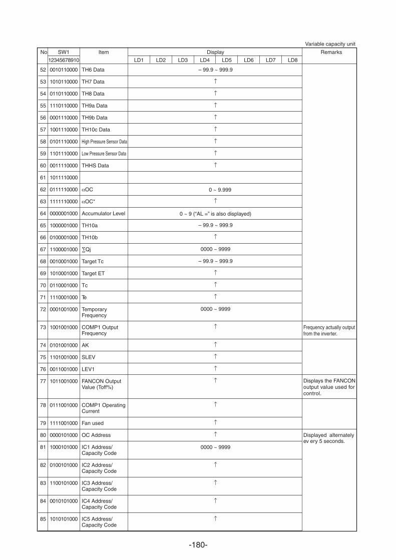
-180-
No SW1 Item Display Remarks
12345678910 LD1 LD2 LD3 LD4 LD5 LD6 LD7 LD8
52
53
54
55
56
57
58
59
60
61
62
63
64
65
66
67
68
69
70
71
72
73
74
75
76
77
78
79
80
81
82
83
84
85
0010110000
1010110000
0110110000
1110110000
0001110000
1001110000
0101110000
1101110000
0011110000
1011110000
0111110000
1111110000
0000001000
1000001000
0100001000
1100001000
0010001000
1010001000
0110001000
1110001000
0001001000
1001001000
0101001000
1101001000
0011001000
1011001000
0111001000
1111001000
0000101000
1000101000
0100101000
1100101000
0010101000
1010101000
TH6 Data
TH7 Data
TH8 Data
TH9a Data
TH9b Data
TH10c Data
High Pressure Sensor Data
Low Pressure Sensor Data
THHS Data
OC
OC*
Accumulator Level
TH10a
TH10b
Qj
Target Tc
Target ET
Tc
Te
TemporaryFrequency
COMP1 OutputFrequency
AK
SLEV
LEV1
FANCON OutputValue (Toff%)
COMP1 OperatingCurrent
Fan used
OC Address
IC1 Address/Capacity Code
IC2 Address/Capacity Code
IC3 Address/Capacity Code
IC4 Address/Capacity Code
IC5 Address/Capacity Code
– 99.9 ~ 999.9
– 99.9 ~ 999.9
0000 ~ 9999
– 99.9 ~ 999.9
0000 ~ 9999
0 ~ 9 (“AL =” is also displayed)
0000 ~ 9999
Variable capacity unit
Displayed alternatelyev ery 5 seconds.
0 ~ 9.999
Frequency actually outputfrom the inverter.
Displays the FANCON output value used for control.
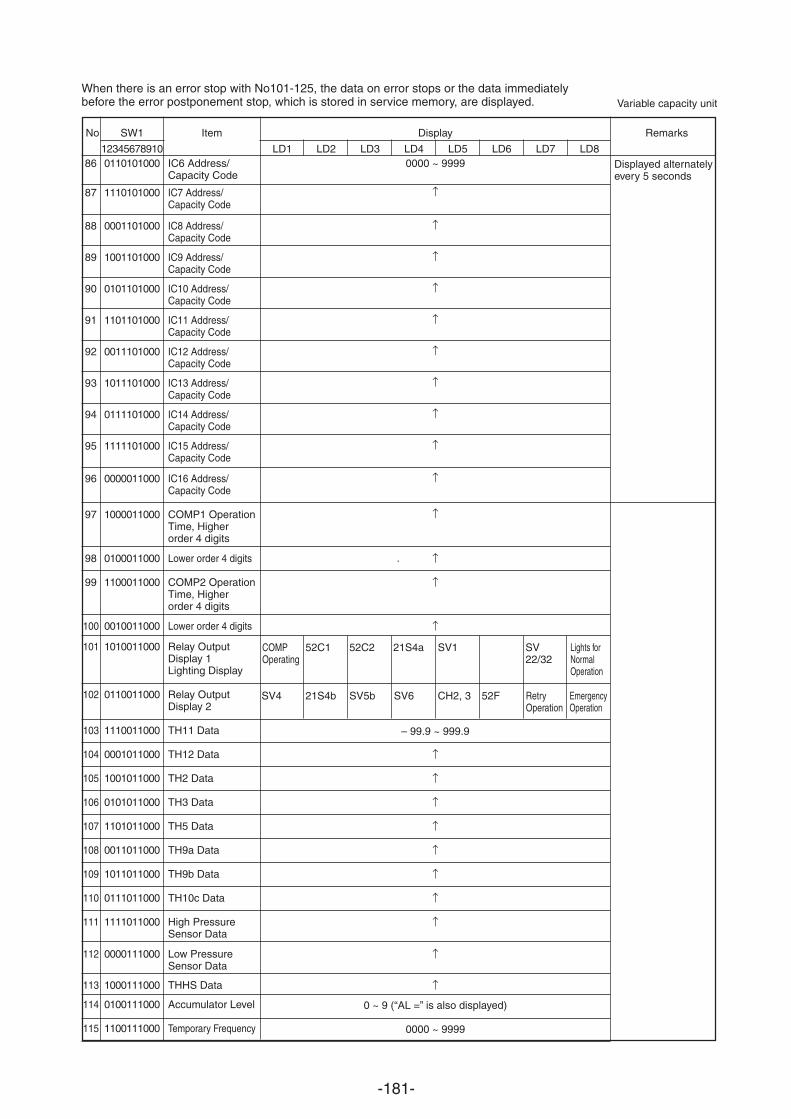
-181-
IC6 Address/Capacity Code
IC7 Address/Capacity Code
IC8 Address/Capacity Code
IC9 Address/Capacity Code
IC10 Address/Capacity Code
IC11 Address/Capacity Code
IC12 Address/Capacity Code
IC13 Address/Capacity Code
IC14 Address/Capacity Code
IC15 Address/Capacity Code
IC16 Address/Capacity Code
COMP1 OperationTime, Higherorder 4 digits
Lower order 4 digits
COMP2 OperationTime, Higherorder 4 digits
Lower order 4 digits
Relay OutputDisplay 1Lighting Display
Relay OutputDisplay 2
TH11 Data
TH12 Data
TH2 Data
TH3 Data
TH5 Data
TH9a Data
TH9b Data
TH10c Data
High PressureSensor Data
Low PressureSensor Data
THHS Data
Accumulator Level
Temporary Frequency
When there is an error stop with No101-125, the data on error stops or the data immediatelybefore the error postponement stop, which is stored in service memory, are displayed.
No SW1 Item Display Remarks
12345678910 LD1 LD2 LD3 LD4 LD5 LD6 LD7 LD886
87
88
89
90
91
92
93
94
95
96
97
98
99
100
101
102
103
104
105
106
107
108
109
110
111
112
113
114
115
0110101000
1110101000
0001101000
1001101000
0101101000
1101101000
0011101000
1011101000
0111101000
1111101000
0000011000
1000011000
0100011000
1100011000
0010011000
1010011000
0110011000
1110011000
0001011000
1001011000
0101011000
1101011000
0011011000
1011011000
0111011000
1111011000
0000111000
1000111000
0100111000
1100111000
– 99.9 ~ 999.9
0 ~ 9 (“AL =” is also displayed)
0000 ~ 9999
0000 ~ 9999
COMPOperating
52C1 52C2 21S4a SV22/32
SV4 21S4b SV5b SV6 52F RetryOperation
Lights forNormalOperation
SV1
CH2, 3 EmergencyOperation
Variable capacity unit
Displayed alternatelyevery 5 seconds
.
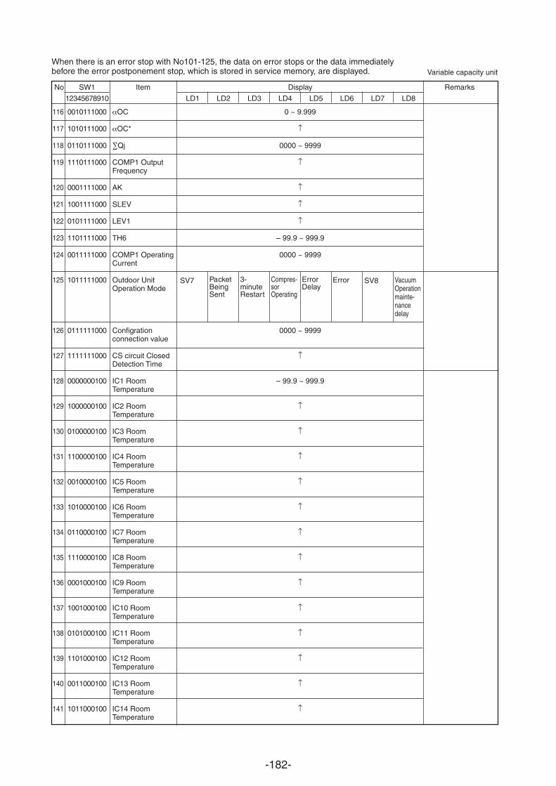
-182-
0 ~ 9.999
0000 ~ 9999
– 99.9 ~ 999.9
0000 ~ 9999
0000 ~ 9999
– 99.9 ~ 999.9
0010111000
1010111000
0110111000
1110111000
0001111000
1001111000
0101111000
1101111000
0011111000
1011111000
0111111000
1111111000
0000000100
1000000100
0100000100
1100000100
0010000100
1010000100
0110000100
1110000100
0001000100
1001000100
0101000100
1101000100
0011000100
1011000100
OC
OC*
Qj
COMP1 OutputFrequency
AK
SLEV
LEV1
TH6
COMP1 OperatingCurrent
Outdoor UnitOperation Mode
Configrationconnection value
CS circuit ClosedDetection Time
IC1 RoomTemperature
IC2 RoomTemperature
IC3 RoomTemperature
IC4 RoomTemperature
IC5 RoomTemperature
IC6 RoomTemperature
IC7 RoomTemperature
IC8 RoomTemperature
IC9 RoomTemperature
IC10 RoomTemperature
IC11 RoomTemperature
IC12 RoomTemperature
IC13 RoomTemperature
IC14 RoomTemperature
No SW1 Item Display Remarks
12345678910 LD1 LD2 LD3 LD4 LD5 LD6 LD7 LD8
116
117
118
119
120
121
122
123
124
125
126
127
128
129
130
131
132
133
134
135
136
137
138
139
140
141
PacketBeingSent
3-minuteRestart
Compres-sorOperating
Error VacuumOperationmainte-nancedelay
ErrorDelay
When there is an error stop with No101-125, the data on error stops or the data immediatelybefore the error postponement stop, which is stored in service memory, are displayed. Variable capacity unit
SV7 SV8
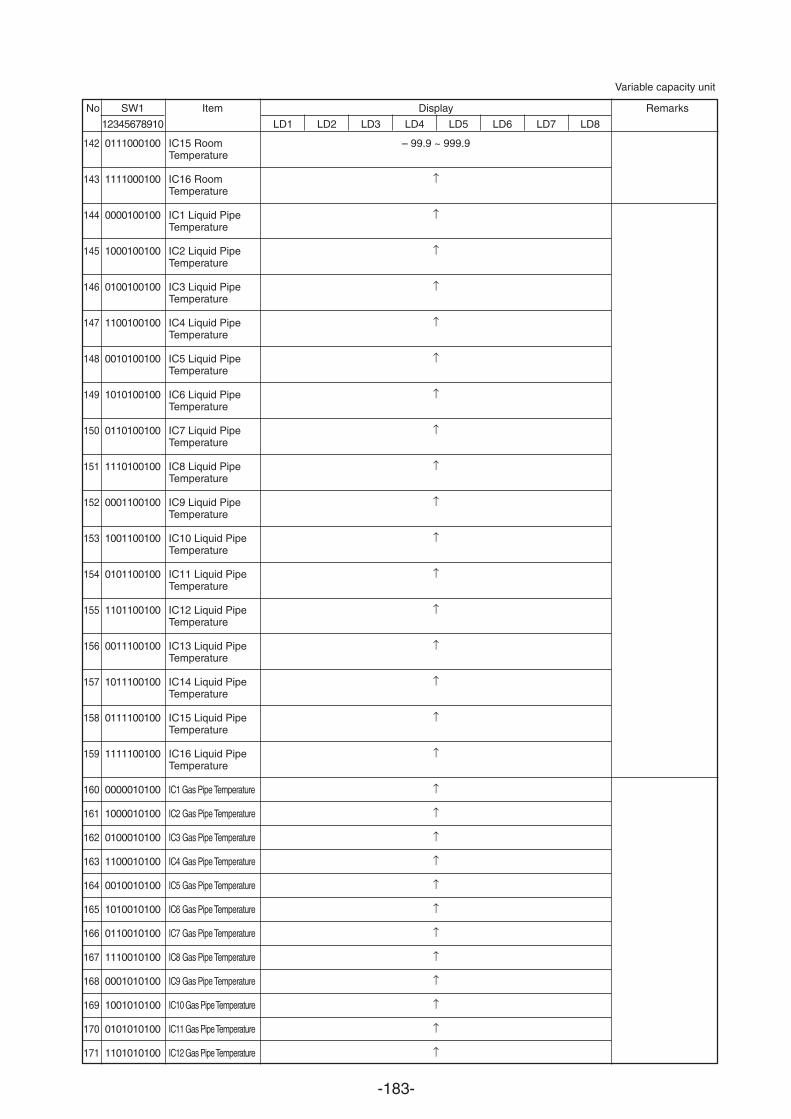
-183-
No SW1 Item Display Remarks
12345678910 LD1 LD2 LD3 LD4 LD5 LD6 LD7 LD8
142
143
144
145
146
147
148
149
150
151
152
153
154
155
156
157
158
159
160
161
162
163
164
165
166
167
168
169
170
171
0111000100
1111000100
0000100100
1000100100
0100100100
1100100100
0010100100
1010100100
0110100100
1110100100
0001100100
1001100100
0101100100
1101100100
0011100100
1011100100
0111100100
1111100100
0000010100
1000010100
0100010100
1100010100
0010010100
1010010100
0110010100
1110010100
0001010100
1001010100
0101010100
1101010100
IC15 RoomTemperature
IC16 RoomTemperature
IC1 Liquid PipeTemperature
IC2 Liquid PipeTemperature
IC3 Liquid PipeTemperature
IC4 Liquid PipeTemperature
IC5 Liquid PipeTemperature
IC6 Liquid PipeTemperature
IC7 Liquid PipeTemperature
IC8 Liquid PipeTemperature
IC9 Liquid PipeTemperature
IC10 Liquid PipeTemperature
IC11 Liquid PipeTemperature
IC12 Liquid PipeTemperature
IC13 Liquid PipeTemperature
IC14 Liquid PipeTemperature
IC15 Liquid PipeTemperature
IC16 Liquid PipeTemperature
IC1 Gas Pipe Temperature
IC2 Gas Pipe Temperature
IC3 Gas Pipe Temperature
IC4 Gas Pipe Temperature
IC5 Gas Pipe Temperature
IC6 Gas Pipe Temperature
IC7 Gas Pipe Temperature
IC8 Gas Pipe Temperature
IC9 Gas Pipe Temperature
IC10 Gas Pipe Temperature
IC11 Gas Pipe Temperature
IC12 Gas Pipe Temperature
– 99.9 ~ 999.9
Variable capacity unit
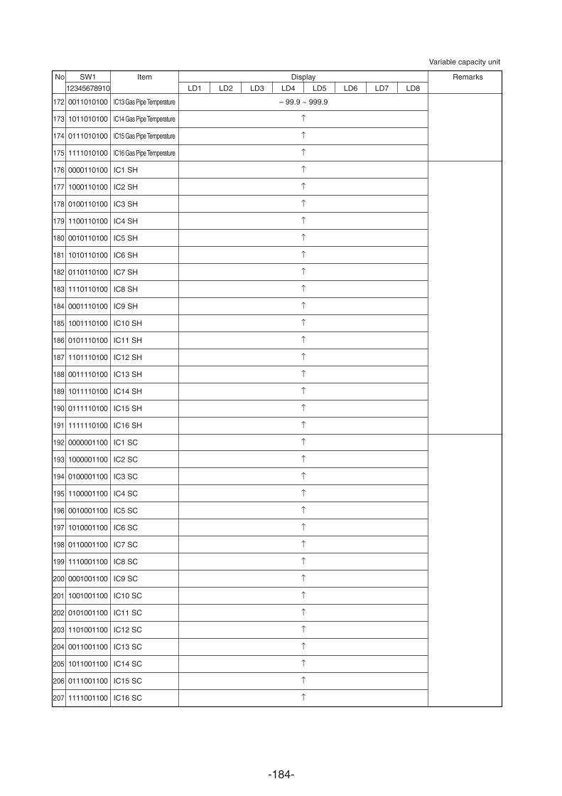
-184-
No SW1 Item Display Remarks
12345678910 LD1 LD2 LD3 LD4 LD5 LD6 LD7 LD8
172
173
174
175
176
177
178
179
180
181
182
183
184
185
186
187
188
189
190
191
192
193
194
195
196
197
198
199
200
201
202
203
204
205
206
207
0011010100
1011010100
0111010100
1111010100
0000110100
1000110100
0100110100
1100110100
0010110100
1010110100
0110110100
1110110100
0001110100
1001110100
0101110100
1101110100
0011110100
1011110100
0111110100
1111110100
0000001100
1000001100
0100001100
1100001100
0010001100
1010001100
0110001100
1110001100
0001001100
1001001100
0101001100
1101001100
0011001100
1011001100
0111001100
1111001100
IC13 Gas Pipe Temperature
IC14 Gas Pipe Temperature
IC15 Gas Pipe Temperature
IC16 Gas Pipe Temperature
IC1 SH
IC2 SH
IC3 SH
IC4 SH
IC5 SH
IC6 SH
IC7 SH
IC8 SH
IC9 SH
IC10 SH
IC11 SH
IC12 SH
IC13 SH
IC14 SH
IC15 SH
IC16 SH
IC1 SC
IC2 SC
IC3 SC
IC4 SC
IC5 SC
IC6 SC
IC7 SC
IC8 SC
IC9 SC
IC10 SC
IC11 SC
IC12 SC
IC13 SC
IC14 SC
IC15 SC
IC16 SC
– 99.9 ~ 999.9
Variable capacity unit
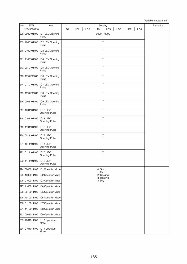
-185-
No SW1 Item Display Remarks
12345678910 LD1 LD2 LD3 LD4 LD5 LD6 LD7 LD8
208
209
210
211
212
213
214
215
216
217
218
219
220
221
222
223
224
225
226
227
228
229
230
231
232
233
234
0000101100
1000101100
0100101100
1100101100
0010101100
10101011000
0110101100
11101011000
0001101100
1001101100
0101101100
1101101100
0011101100
1011101100
0111101100
1111101100
0000011100
1000011100
0100011100
1100011100
0010011100
1010011100
0110011100
1110011100
0001011100
1001011100
0101011100
IC1 LEV OpeningPulse
IC2 LEV OpeningPulse
IC3 LEV OpeningPulse
IC4 LEV OpeningPulse
IC5 LEV OpeningPulse
IC6 LEV OpeningPulse
IC7 LEV OpeningPulse
IC8 LEV OpeningPulse
IC9 LEV OpeningPulse
IC10 LEVOpening Pulse
IC11 LEVOpening Pulse
IC12 LEVOpening Pulse
IC13 LEVOpening Pulse
IC14 LEVOpening Pulse
IC15 LEVOpening Pulse
IC16 LEVOpening Pulse
IC1 Operation Mode
IC2 Operation Mode
IC3 Operation Mode
IC4 Operation Mode
IC5 Operation Mode
IC6 Operation Mode
IC7 Operation Mode
IC8 Operation Mode
IC9 Operation Mode
IC10 OperationMode
IC11 OperationMode
0000 ~ 9999
0: Stop1: Fan2: Cooling3: Heating4: Dry
Variable capacity unit
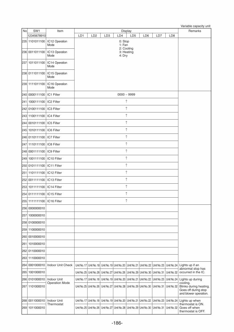
-186-
No SW1 Item Display Remarks
12345678910 LD1 LD2 LD3 LD4 LD5 LD6 LD7 LD8
235
236
237
238
239
240
241
242
243
244
245
246
247
248
249
250
251
252
253
254
255
256
257
258
259
260
261
262
263
264
265
266
267
268
269
1101011100
0011011100
1011011100
0111011100
1111011100
0000111100
1000111100
0100111100
1100111100
0010111100
1010111100
0110111100
1110111100
0001111100
1001111100
0101111100
1101111100
0011111100
1011111100
0111111100
1111111100
0000000010
1000000010
0100000010
1100000010
0010000010
1010000010
0110000010
1110000010
0001000010
1001000010
0101000010
1101000010
0011000010
1011000010
IC12 OperationMode
IC13 OperationMode
IC14 OperationMode
IC15 OperationMode
IC16 OperationMode
IC1 Filter
IC2 Filter
IC3 Filter
IC4 Filter
IC5 Filter
IC6 Filter
IC7 Filter
IC8 Filter
IC9 Filter
IC10 Filter
IC11 Filter
IC12 Filter
IC13 Filter
IC14 Filter
IC15 Filter
IC16 Filter
Indoor Unit Check
Indoor UnitOperation Mode
Indoor UnitThermostat
0000 ~ 9999
Unit No. 17
Unit No. 25
Lights up if anabnormal stop hasoccurred in the IC.
Lights up duringcooling.Blinks during heating.Goes off during stopand blower operation.
Lights up whenthermostat is ON.Goes off whenthermostat is OFF.
0: Stop1: Fan2: Cooling3: Heating4: Dry
Unit No. 18
Unit No. 26
Unit No. 19
Unit No. 27
Unit No. 20
Unit No. 28
Unit No. 17
Unit No. 25
Unit No. 17
Unit No. 25
Unit No. 18
Unit No. 26
Unit No. 18
Unit No. 26
Unit No. 19
Unit No. 27
Unit No. 19
Unit No. 27
Unit No. 20
Unit No. 28
Unit No. 20
Unit No. 28
Unit No. 21
Unit No. 29
Unit No. 22
Unit No. 30
Unit No. 23
Unit No. 31
Unit No. 24
Unit No. 32
Unit No. 21
Unit No. 29
Unit No. 21
Unit No. 29
Unit No. 22
Unit No. 30
Unit No. 22
Unit No. 30
Unit No. 23
Unit No. 31
Unit No. 23
Unit No. 31
Unit No. 24
Unit No. 32
Unit No. 24
Unit No. 32
Variable capacity unit
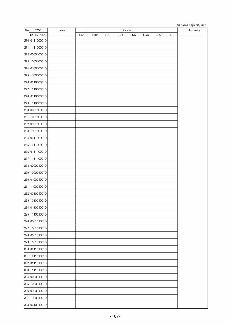
-187-
No SW1 Item Display Remarks
12345678910 LD1 LD2 LD3 LD4 LD5 LD6 LD7 LD8
0111000010
1111000010
0000100010
1000100010
0100100010
1100100010
0010100010
1010100010
0110100010
1110100010
0001100010
1001100010
0101100010
1101100010
0011100010
1011100010
0111100010
1111100010
0000010010
1000010010
0100010010
1100010010
0010010010
1010010010
0110010010
1110010010
0001010010
1001010010
0101010010
1101010010
0011010010
1011010010
0111010010
1111010010
0000110010
1000110010
0100110010
1100110010
0010110010
270
271
272
273
274
275
276
277
278
279
280
281
282
283
284
285
286
287
288
289
290
291
292
293
294
295
296
297
298
299
300
301
302
303
304
305
306
307
308
Variable capacity unit
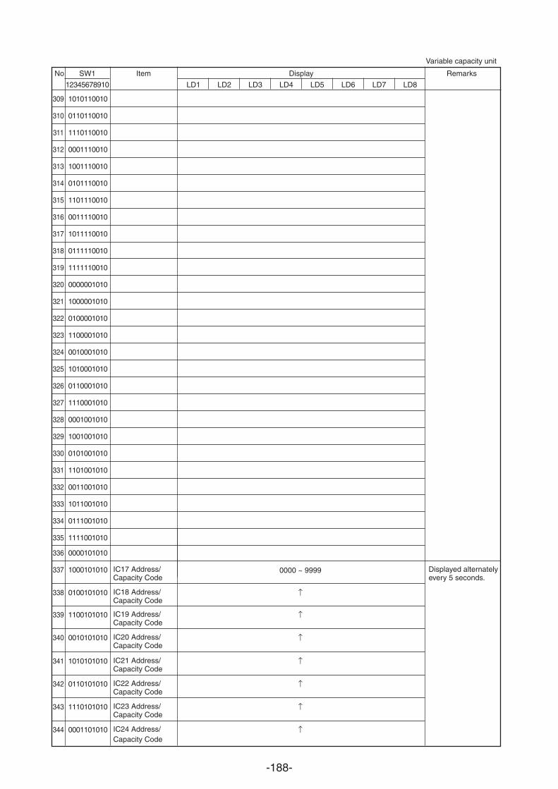
-188-
No SW1 Item Display Remarks
12345678910 LD1 LD2 LD3 LD4 LD5 LD6 LD7 LD8
1010110010
0110110010
1110110010
0001110010
1001110010
0101110010
1101110010
0011110010
1011110010
0111110010
1111110010
0000001010
1000001010
0100001010
1100001010
0010001010
1010001010
0110001010
1110001010
0001001010
1001001010
0101001010
1101001010
0011001010
1011001010
0111001010
1111001010
0000101010
1000101010
0100101010
1100101010
0010101010
1010101010
0110101010
1110101010
0001101010
309
310
311
312
313
314
315
316
317
318
319
320
321
322
323
324
325
326
327
328
329
330
331
332
333
334
335
336
337
338
339
340
341
342
343
344
IC17 Address/Capacity Code
IC18 Address/Capacity Code
IC19 Address/Capacity Code
IC20 Address/Capacity Code
IC21 Address/Capacity Code
IC22 Address/Capacity Code
IC23 Address/Capacity Code
IC24 Address/Capacity Code
0000 ~ 9999 Displayed alternatelyevery 5 seconds.
Variable capacity unit
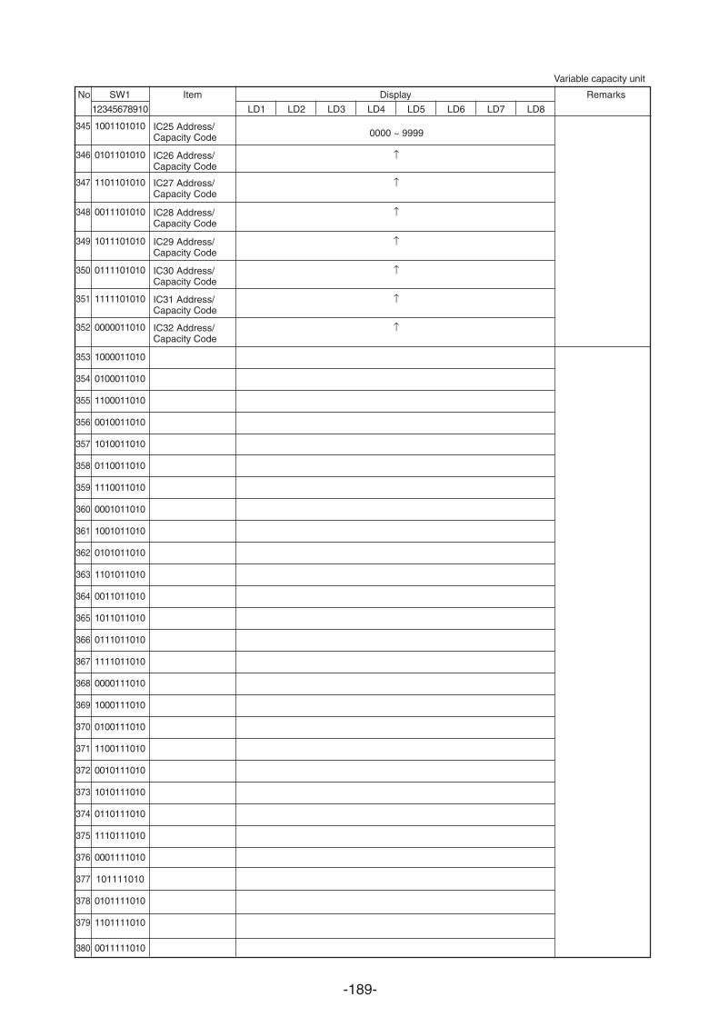
-189-
No SW1 Item Display Remarks
12345678910 LD1 LD2 LD3 LD4 LD5 LD6 LD7 LD8
345
346
347
348
349
350
351
352
353
354
355
356
357
358
359
360
361
362
363
364
365
366
367
368
369
370
371
372
373
374
375
376
377
378
379
380
1001101010
0101101010
1101101010
0011101010
1011101010
0111101010
1111101010
0000011010
1000011010
0100011010
1100011010
0010011010
1010011010
0110011010
1110011010
0001011010
1001011010
0101011010
1101011010
0011011010
1011011010
0111011010
1111011010
0000111010
1000111010
0100111010
1100111010
0010111010
1010111010
0110111010
1110111010
0001111010
101111010
0101111010
1101111010
0011111010
Variable capacity unit
IC25 Address/Capacity Code
IC26 Address/Capacity Code
IC27 Address/Capacity Code
IC28 Address/Capacity Code
IC29 Address/Capacity Code
IC30 Address/Capacity Code
IC31 Address/Capacity Code
IC32 Address/Capacity Code
0000 ~ 9999
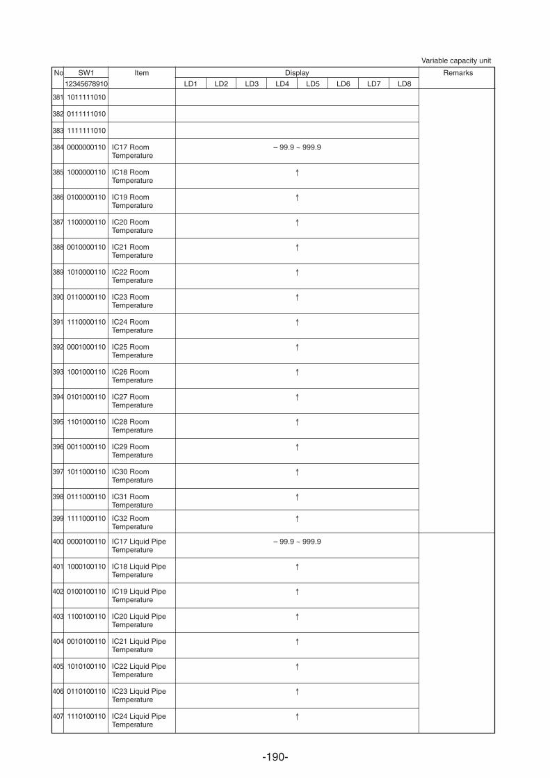
-190-
No SW1 Item Display Remarks
12345678910 LD1 LD2 LD3 LD4 LD5 LD6 LD7 LD8
381
382
383
384
385
386
387
388
389
390
391
392
393
394
395
396
397
398
399
400
401
402
403
404
405
406
407
1011111010
0111111010
1111111010
0000000110
1000000110
0100000110
1100000110
0010000110
1010000110
0110000110
1110000110
0001000110
1001000110
0101000110
1101000110
0011000110
1011000110
0111000110
1111000110
0000100110
1000100110
0100100110
1100100110
0010100110
1010100110
0110100110
1110100110
IC17 RoomTemperature
IC18 RoomTemperature
IC19 RoomTemperature
IC20 RoomTemperature
IC21 RoomTemperature
IC22 RoomTemperature
IC23 RoomTemperature
IC24 RoomTemperature
IC25 RoomTemperature
IC26 RoomTemperature
IC27 RoomTemperature
IC28 RoomTemperature
IC29 RoomTemperature
IC30 RoomTemperature
IC31 RoomTemperature
IC32 RoomTemperature
IC17 Liquid PipeTemperature
IC18 Liquid PipeTemperature
IC19 Liquid PipeTemperature
IC20 Liquid PipeTemperature
IC21 Liquid PipeTemperature
IC22 Liquid PipeTemperature
IC23 Liquid PipeTemperature
IC24 Liquid PipeTemperature
– 99.9 ~ 999.9
– 99.9 ~ 999.9
Variable capacity unit
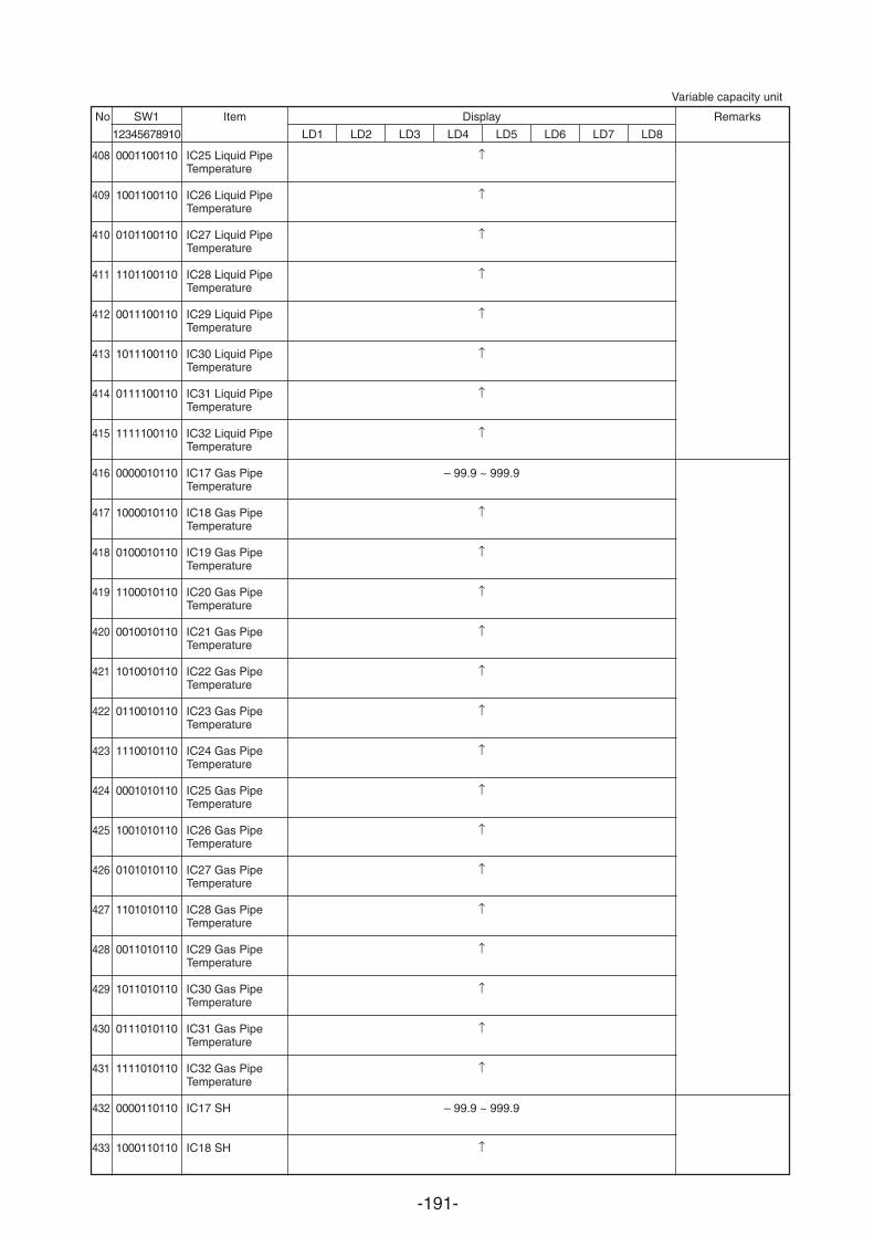
-191-
No SW1 Item Display Remarks
12345678910 LD1 LD2 LD3 LD4 LD5 LD6 LD7 LD8
408
409
410
411
412
413
414
415
416
417
418
419
420
421
422
423
424
425
426
427
428
429
430
431
432
433
0001100110
1001100110
0101100110
1101100110
0011100110
1011100110
0111100110
1111100110
0000010110
1000010110
0100010110
1100010110
0010010110
1010010110
0110010110
1110010110
0001010110
1001010110
0101010110
1101010110
0011010110
1011010110
0111010110
1111010110
0000110110
1000110110
IC25 Liquid PipeTemperature
IC26 Liquid PipeTemperature
IC27 Liquid PipeTemperature
IC28 Liquid PipeTemperature
IC29 Liquid PipeTemperature
IC30 Liquid PipeTemperature
IC31 Liquid PipeTemperature
IC32 Liquid PipeTemperature
IC17 Gas PipeTemperature
IC18 Gas PipeTemperature
IC19 Gas PipeTemperature
IC20 Gas PipeTemperature
IC21 Gas PipeTemperature
IC22 Gas PipeTemperature
IC23 Gas PipeTemperature
IC24 Gas PipeTemperature
IC25 Gas PipeTemperature
IC26 Gas PipeTemperature
IC27 Gas PipeTemperature
IC28 Gas PipeTemperature
IC29 Gas PipeTemperature
IC30 Gas PipeTemperature
IC31 Gas PipeTemperature
IC32 Gas PipeTemperature
IC17 SH
IC18 SH
– 99.9 ~ 999.9
– 99.9 ~ 999.9
Variable capacity unit
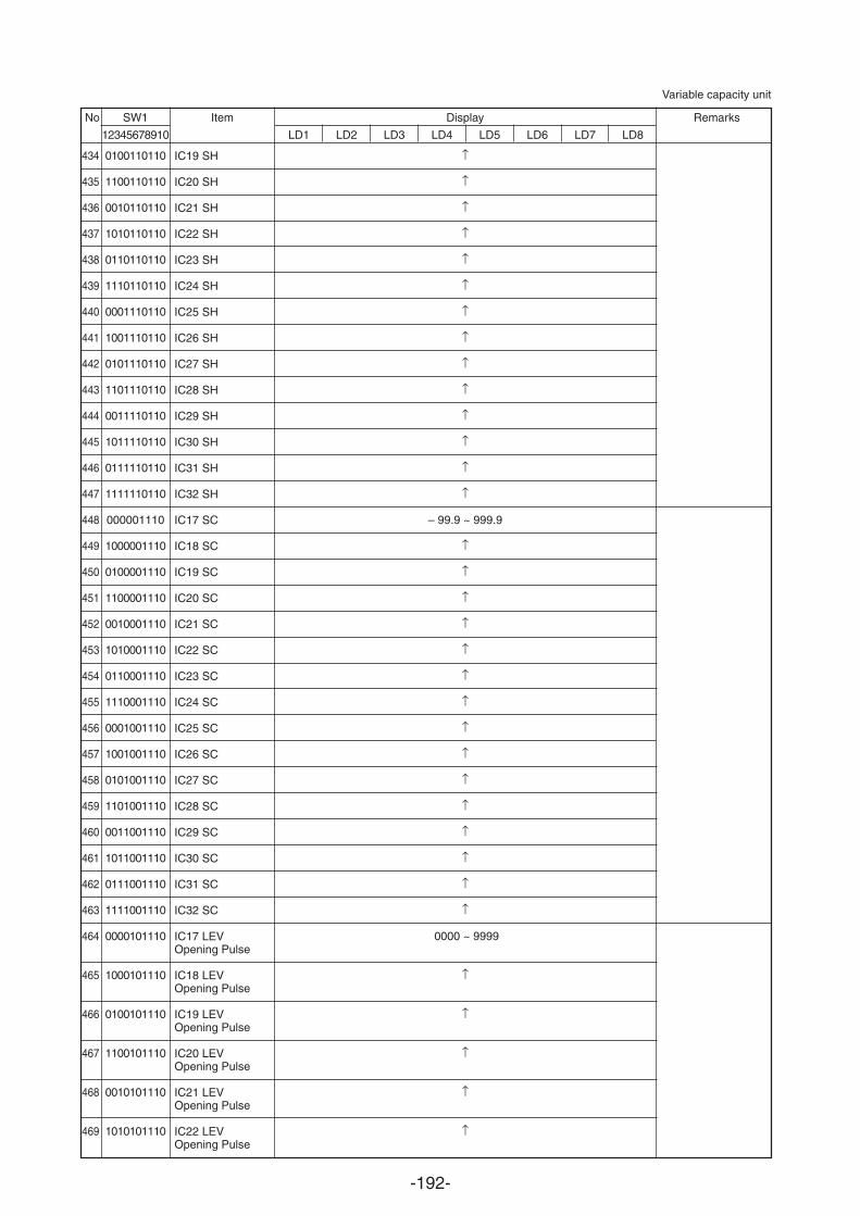
-192-
No SW1 Item Display Remarks
12345678910 LD1 LD2 LD3 LD4 LD5 LD6 LD7 LD8
Variable capacity unit
434
435
436
437
438
439
440
441
442
443
444
445
446
447
448
449
450
451
452
453
454
455
456
457
458
459
460
461
462
463
464
465
466
467
468
469
0100110110
1100110110
0010110110
1010110110
0110110110
1110110110
0001110110
1001110110
0101110110
1101110110
0011110110
1011110110
0111110110
1111110110
000001110
1000001110
0100001110
1100001110
0010001110
1010001110
0110001110
1110001110
0001001110
1001001110
0101001110
1101001110
0011001110
1011001110
0111001110
1111001110
0000101110
1000101110
0100101110
1100101110
0010101110
1010101110
IC19 SH
IC20 SH
IC21 SH
IC22 SH
IC23 SH
IC24 SH
IC25 SH
IC26 SH
IC27 SH
IC28 SH
IC29 SH
IC30 SH
IC31 SH
IC32 SH
IC17 SC
IC18 SC
IC19 SC
IC20 SC
IC21 SC
IC22 SC
IC23 SC
IC24 SC
IC25 SC
IC26 SC
IC27 SC
IC28 SC
IC29 SC
IC30 SC
IC31 SC
IC32 SC
IC17 LEVOpening Pulse
IC18 LEVOpening Pulse
IC19 LEVOpening Pulse
IC20 LEVOpening Pulse
IC21 LEVOpening Pulse
IC22 LEVOpening Pulse
– 99.9 ~ 999.9
0000 ~ 9999
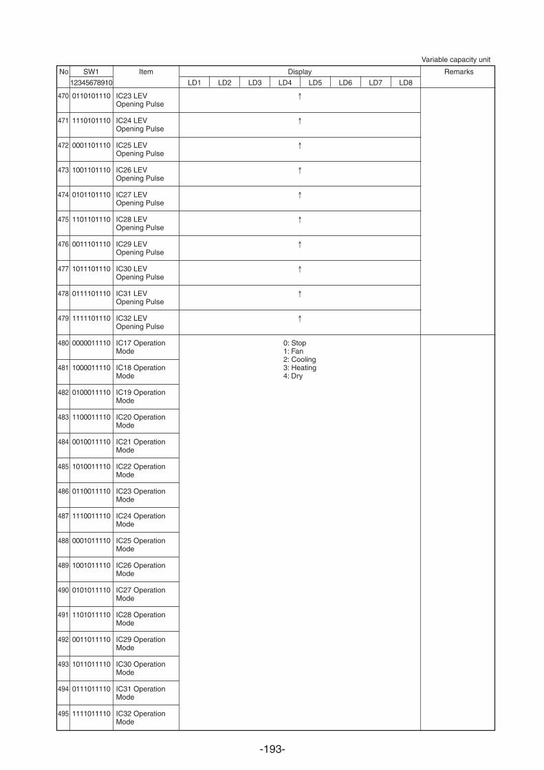
-193-
No SW1 Item Display Remarks
12345678910 LD1 LD2 LD3 LD4 LD5 LD6 LD7 LD8
Variable capacity unit
470
471
472
473
474
475
476
477
478
479
480
481
482
483
484
485
486
487
488
489
490
491
492
493
494
495
0110101110
1110101110
0001101110
1001101110
0101101110
1101101110
0011101110
1011101110
0111101110
1111101110
0000011110
1000011110
0100011110
1100011110
0010011110
1010011110
0110011110
1110011110
0001011110
1001011110
0101011110
1101011110
0011011110
1011011110
0111011110
1111011110
IC23 LEVOpening Pulse
IC24 LEVOpening Pulse
IC25 LEVOpening Pulse
IC26 LEVOpening Pulse
IC27 LEVOpening Pulse
IC28 LEVOpening Pulse
IC29 LEVOpening Pulse
IC30 LEVOpening Pulse
IC31 LEVOpening Pulse
IC32 LEVOpening Pulse
IC17 OperationMode
IC18 OperationMode
IC19 OperationMode
IC20 OperationMode
IC21 OperationMode
IC22 OperationMode
IC23 OperationMode
IC24 OperationMode
IC25 OperationMode
IC26 OperationMode
IC27 OperationMode
IC28 OperationMode
IC29 OperationMode
IC30 OperationMode
IC31 OperationMode
IC32 OperationMode
0: Stop1: Fan2: Cooling3: Heating4: Dry
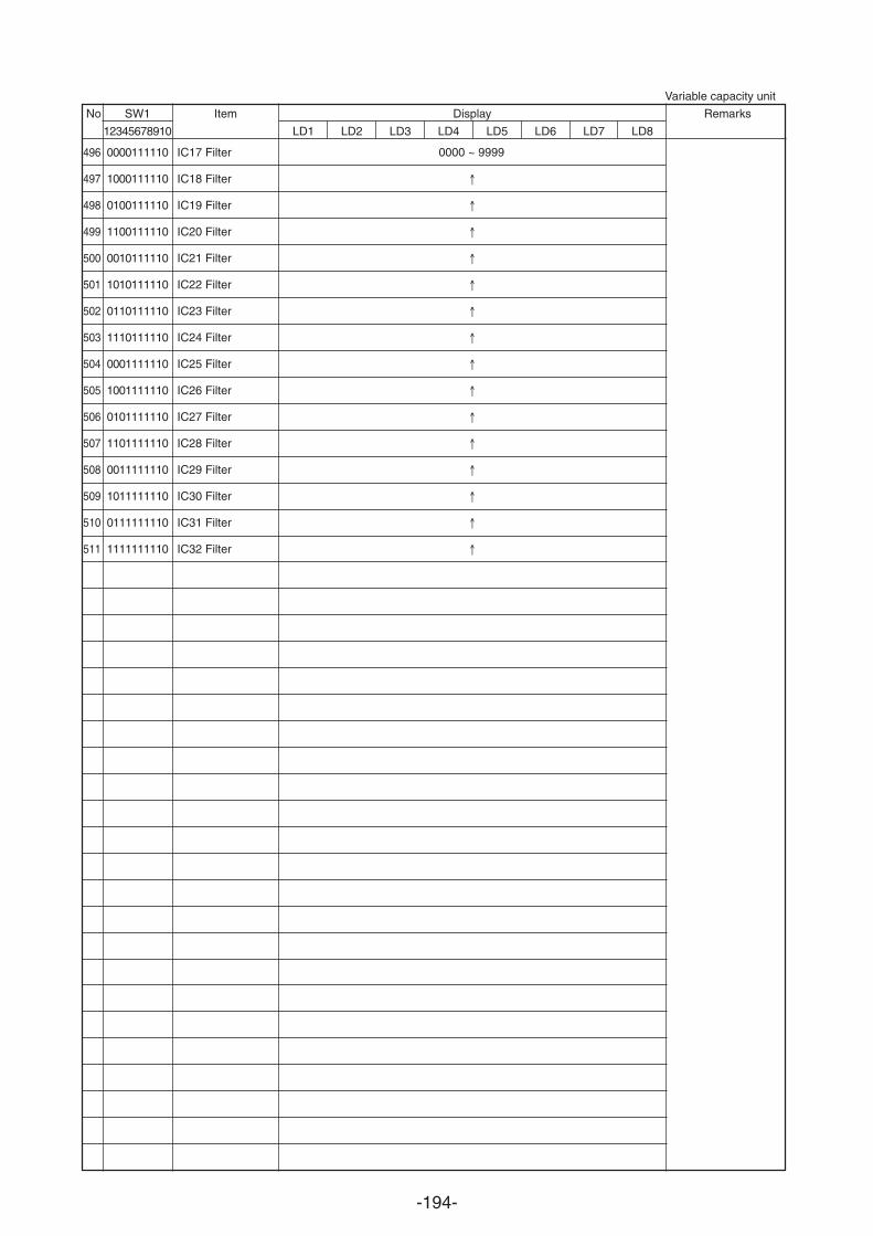
-194-
No SW1 Item Display Remarks
12345678910 LD1 LD2 LD3 LD4 LD5 LD6 LD7 LD8
Variable capacity unit
496
497
498
499
500
501
502
503
504
505
506
507
508
509
510
511
0000111110
1000111110
0100111110
1100111110
0010111110
1010111110
0110111110
1110111110
0001111110
1001111110
0101111110
1101111110
0011111110
1011111110
0111111110
1111111110
IC17 Filter
IC18 Filter
IC19 Filter
IC20 Filter
IC21 Filter
IC22 Filter
IC23 Filter
IC24 Filter
IC25 Filter
IC26 Filter
IC27 Filter
IC28 Filter
IC29 Filter
IC30 Filter
IC31 Filter
IC32 Filter
0000 ~ 9999
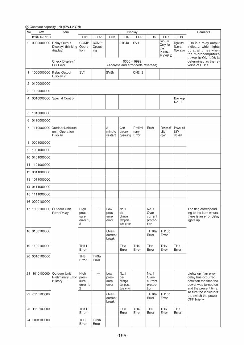
-195-
SV2, 3Only forthePUHN-P-YMF-C
No SW1 Item Display Remarks
12345678910 LD1 LD2 LD3 LD4 LD5 LD6 LD7 LD8
Relay OutputDisplay 1 (blinkingdisplay)
Check Display 1OC Error
Relay OutputDisplay 2
Special Control
Outdoor Unit (sub-unit) OperationDisplay
Outdoor UnitPreliminary ErrorHistory
COMPOpera-tion
SV4
Highpres-sureerror 1,2
TH11Error
TH8Error
Highpres-sureerror 1,2
TH11Error
TH8Error
COMP 1Operat-ing
—
TH9aError
—
TH9aError
SV5b
3-minuterestart
Lowpres-sureerror
Over-currentbreak
Lowpres-sureerror
Over-currentbreak
21S4a
Com-pressoroperating
No. 1dis-chargetempera-ture error
TH3Error
No. 1dis-chargetempera-ture error
TH3Error
SV1
CH2, 3
Prelimi-naryError
TH4Error
TH4Error
Error
No. 1Over-currentprotec-tion
TH10aError
TH5Error
No. 1Over-currentprotec-tion
TH10aError
TH5Error
Power offLEVopen
TH10bError
TH6Error
TH10bError
TH6Error
Lights forNormalOperation
BackupNo. 9
Power offLEVclosed
TH7Error
TH7Error
LD8 is a relay outputindicator which lightsup at all times whenthe microcomputer’spower is ON. LD8 isdetermined as the re-verse of CH11.
The flag correspond-ing to the item wherethere is an error delaylights up.
Lights up if an errordelay has occurredbetween the time thepower was turned onand the present time.To turn the indicatorsoff, switch the powerOFF briefly.
0000 ~ 9999(Address and error code reversed)
2
Constant capacity unit (SW4-2 ON)
0
1
2
3
4
5
6
7
8
9
10
11
12
13
14
15
16
17
18
19
20
21
22
23
24
0000000000
1000000000
0100000000
1100000000
0010000000
1010000000
0110000000
1110000000
0001000000
1001000000
0101000000
1101000000
0011000000
1011000000
0111000000
1111000000
0000100000
1000100000
0100100000
1100100000
0010100000
1010100000
0110100000
1110100000
0001100000
Outdoor Unit Error Delay
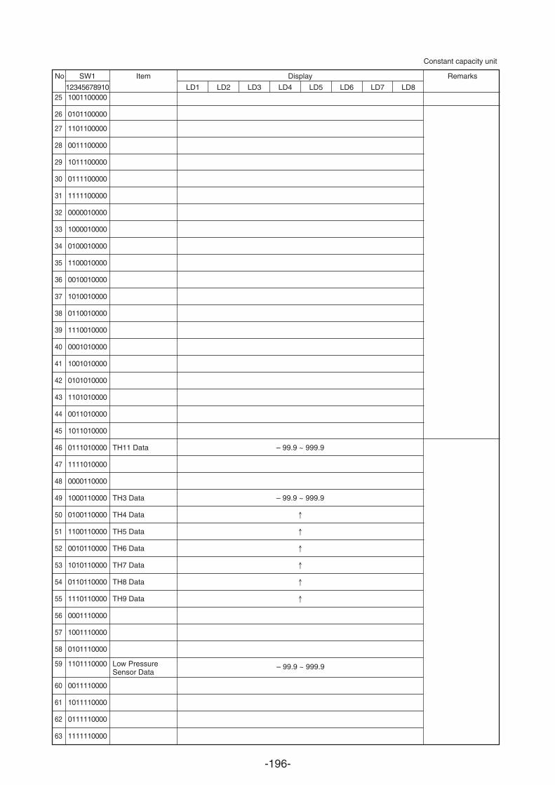
-196-
No SW1 Item Display Remarks
12345678910 LD1 LD2 LD3 LD4 LD5 LD6 LD7 LD825
26
27
28
29
30
31
32
33
34
35
36
37
38
39
40
41
42
43
44
45
46
47
48
49
50
51
52
53
54
55
56
57
58
59
60
61
62
63
1001100000
0101100000
1101100000
0011100000
1011100000
0111100000
1111100000
0000010000
1000010000
0100010000
1100010000
0010010000
1010010000
0110010000
1110010000
0001010000
1001010000
0101010000
1101010000
0011010000
1011010000
0111010000
1111010000
0000110000
1000110000
0100110000
1100110000
0010110000
1010110000
0110110000
1110110000
0001110000
1001110000
0101110000
1101110000
0011110000
1011110000
0111110000
1111110000
TH11 Data
TH3 Data
TH4 Data
TH5 Data
TH6 Data
TH7 Data
TH8 Data
TH9 Data
Low PressureSensor Data
– 99.9 ~ 999.9
– 99.9 ~ 999.9
– 99.9 ~ 999.9
Constant capacity unit
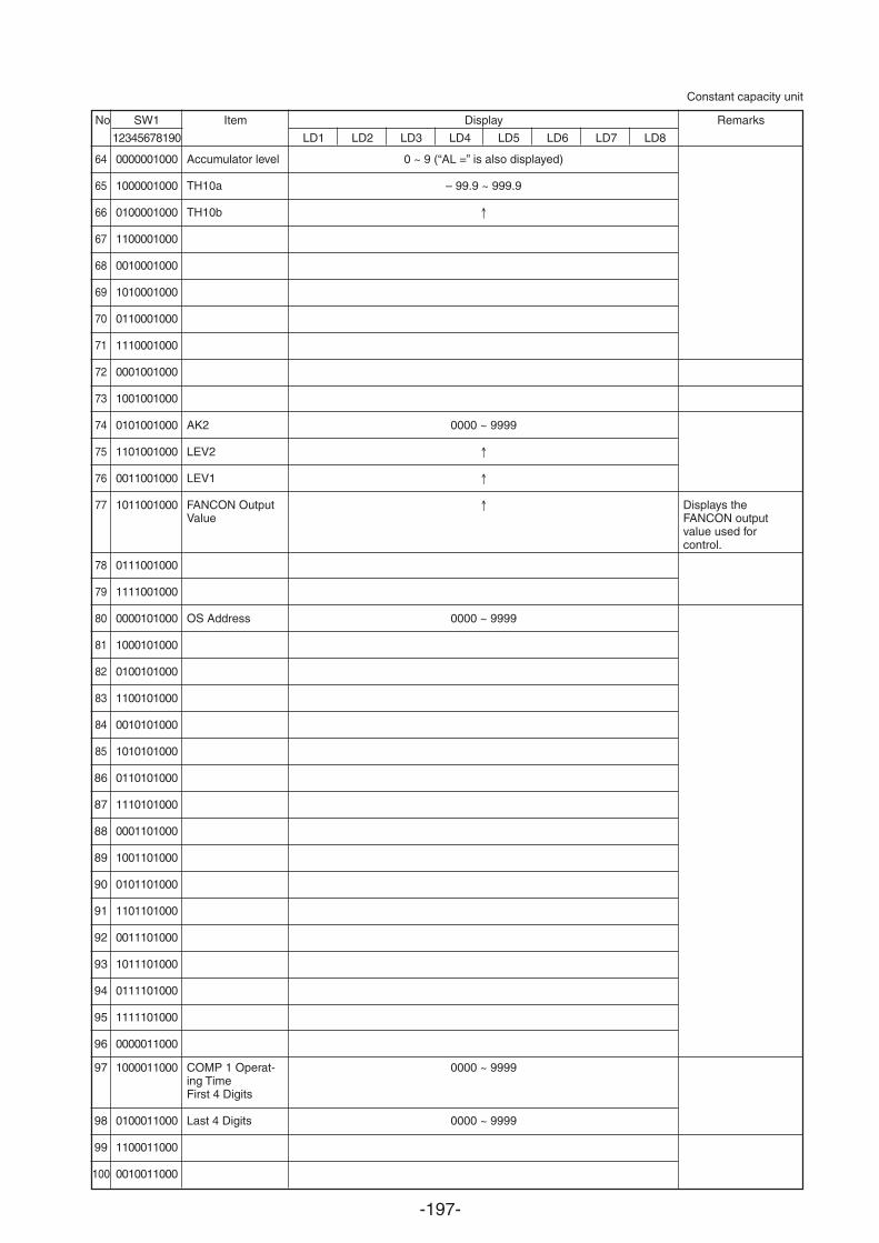
-197-
No SW1 Item Display Remarks
12345678190 LD1 LD2 LD3 LD4 LD5 LD6 LD7 LD8
Constant capacity unit
64
65
66
67
68
69
70
71
72
73
74
75
76
77
78
79
80
81
82
83
84
85
86
87
88
89
90
91
92
93
94
95
96
97
98
99
100
0000001000
1000001000
0100001000
1100001000
0010001000
1010001000
0110001000
1110001000
0001001000
1001001000
0101001000
1101001000
0011001000
1011001000
0111001000
1111001000
0000101000
1000101000
0100101000
1100101000
0010101000
1010101000
0110101000
1110101000
0001101000
1001101000
0101101000
1101101000
0011101000
1011101000
0111101000
1111101000
0000011000
1000011000
0100011000
1100011000
0010011000
Accumulator level
TH10a
TH10b
AK2
LEV2
LEV1
FANCON OutputValue
OS Address
COMP 1 Operat-ing TimeFirst 4 Digits
Last 4 Digits
0 ~ 9 (“AL =” is also displayed)
– 99.9 ~ 999.9
0000 ~ 9999
0000 ~ 9999
0000 ~ 9999
0000 ~ 9999
Displays theFANCON outputvalue used forcontrol.
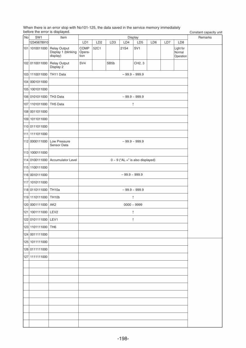
-198-
No SW1 Item Display Remarks
12345678910 LD1 LD2 LD3 LD4 LD5 LD6 LD7 LD8
Constant capacity unit
COMP Light forNormal Operation
Opera-tion
SV4
52C1 21S4 SV1
CH2, 3
101
102
103
104
105
106
107
108
109
110
111
112
113
114
115
116
117
118
119
120
121
122
123
124
125
126
127
1010011000
0110011000
1110011000
0001011000
1001011000
0101011000
1101011000
0011011000
1011011000
0111011000
1111011000
0000111000
1000111000
0100111000
1100111000
0010111000
1010111000
0110111000
1110111000
0001111000
1001111000
0101111000
1101111000
0011111000
1011111000
0111111000
1111111000
Relay OutputDisplay 1 (blinkingdisplay)
Relay OutputDisplay 2
TH11 Data
TH3 Data
TH5 Data
Low PressureSensor Data
Accumulator Level
TH10a
TH10b
AK2
LEV2
LEV1
TH6
SB5b
– 99.9 ~ 999.9
– 99.9 ~ 999.9
– 99.9 ~ 999.9
0 ~ 9 (“AL =” is also displayed)
– 99.9 ~ 999.9
0000 ~ 9999
– 99.9 ~ 999.9
When there is an error stop with No101-125, the data saved in the service memory immediatelybefore the error is displayed.
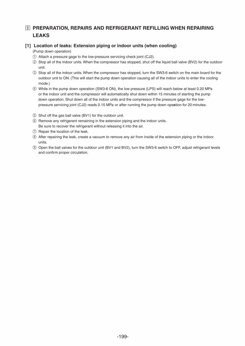
-199-
• PREPARATION, REPAIRS AND REFRIGERANT REFILLING WHEN REPAIRING
LEAKS
[1] Location of leaks: Extension piping or indoor units (when cooling) (Pump down operation)
1 Attach a pressure gage to the low-pressure servicing check joint (CJ2).2 Stop all of the indoor units. When the compressor has stopped, shut off the liquid ball valve (BV2) for the outdoor
unit.
3 Stop all of the indoor units. When the compressor has stopped, turn the SW3-6 switch on the main board for theoutdoor unit to ON. (This will start the pump down operation causing all of the indoor units to enter the coolingmode.)
4 While in the pump down operation (SW3-6 ON), the low pressure (LPS) will reach belo
down operation. Shut down all of the indoor units and the compressor if the pressure gage for the low-
pressure servicing joint (CJ2) reads 0.15 MPa or after running the pump down operation for 20 minutes.
5 Shut off the gas ball valve (BV1) for the outdoor unit.
6 Remove any refrigerant remaining in the extension piping and the indoor units.Be sure to recover the refrigerant without releasing it into the air.
7 Repair the location of the leak.
8 After repairing the leak, create a vacuum to remove any air from inside of the extension piping or the indoorunits.
9 Open the ball valves for the outdoor unit (BV1 and BV2), turn the SW3-6 switch to OFF, adjust refrigerant levelsand confirm proper circulation.
w at least 0.20 MPaor the indoor unit and the compressor will automatically shut down within 15 minutes of starting the pump
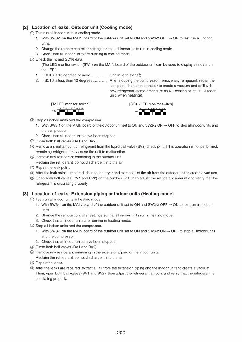
-200-
1 2 3 4 5 6 7 8 9 10
ON1
ON2 3 4 5 6 7 8 9 10
Stop all indoor units and the compressor.1. With SW3-1 on the MAIN board of the outdoor unit set to ON and SW3-2 ON OFF to stop all indoor units and
the compressor.2. Check that all indoor units have been stopped.Close both ball valves (BV1 and BV2).
Remove a small amount of refrigerant from the liquid ball valve (BV2) check joint. If this operation is not performed,remaining refrigerant may cause the unit to malfunction.Remove any refrigerant remaining in the outdoor unit.
Reclaim the refrigerant; do not discharge it into the air.Repair the leak point.After the leak point is repaired, change the dryer and extract all of the air from the outdoor unit to create a vacuum.
Open both ball valves (BV1 and BV2) on the outdoor unit, then adjust the refrigerant amount and verify that therefrigerant is circulating properly.
[3] Location of leaks: Extension piping or indoor units (Heating mode)Test run all indoor units in heating mode.1. With SW3-1 on the MAIN board of the outdoor unit set to ON and SW3-2 OFF ON to test run all indoor
units.
2. Change the remote controller settings so that all indoor units run in heating mode.3. Check that all indoor units are running in heating mode.Stop all indoor units and the compressor.
1. With SW3-1 on the MAIN board of the outdoor unit set to ON and SW3-2 ON OFF to stop all indoor unitsand the compressor.
2. Check that all indoor units have been stopped.
Close both ball valves (BV1 and BV2).Remove any refrigerant remaining in the extension piping or the indoor units.Reclaim the refrigerant; do not discharge it into the air.
Repair the leaks.After the leaks are repaired, extract all air from the extension piping and the indoor units to create a vacuum.Then, open both ball valves (BV1 and BV2), then adjust the refrigerant amount and verify that the refrigerant is
circulating properly.
[Tc LED monitor switch] [SC16 LED monitor switch]
[2] Location of leaks: Outdoor unit (Cooling mode)1
2
Test run all indoor units in cooling mode.1. With SW3-1 on the MAIN board of the outdoor unit set to ON and SW3-2 OFF ON to test run all indoor
units.
2. Change the remote controller settings so that all indoor units run in cooling mode.3. Check that all indoor units are running in cooling mode.Check the Tc and SC16 data.
(The LED monitor switch (SW1) on the MAIN board of the outdoor unit can be used to display this data onthe LED.)
1. If SC16 is 10 degrees or more ................. Continue to step 3.
2. If SC16 is less than 10 degrees ............... After stopping the compressor, remove any refrigerant, repair theleak point, then extract the air to create a vacuum and refill withnew refrigerant (same procedure as 4. Location of leaks: Outdoorunit (when heating)).
3
4
5
6
7
89
1
2
3
4
5
6
-201-
[4] Location of leaks: Outdoor unit (when heating)Remove any refrigerant from the entire system (outdoor unit, extension piping and indoor units).Reclaim the refrigerant; do not discharge it into the air.Repair the leaks.
After the leaks are repaired, replace the dryer with a new one and extract all of the air from the entire system tocreate a vacuum. Then, refill with refrigerant until it reaches the calculated specification (outdoor unit + extensionpiping + indoor units). Refer to “Chapter 6 ” for more details.
1
2
3
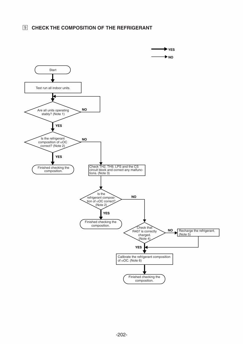
-202-
YES
YES
YES
YES
YES
NO
NO
NO
NO
NO
Start
Test run all indoor units.
Is the refrigerantcomposition of OC
correct? (Note 2)
Finished checking thecomposition.
Check TH2, TH9, LPS and the CScircuit block and correct any malfunc-tions. (Note 3)
Is therefrigerant composi-tion of OC correct?
(Note 2)
Finished checking thecomposition.
Check thatR407 is correctly
charged.(Note 4)
Recharge the refrigerant.(Note 5)
Finished checking thecomposition.
Calibrate the refrigerant compositionof OC. (Note 6)
Are all units operatingstably? (Note 1)
CHECK THE COMPOSITION OF THE REFRIGERANTª
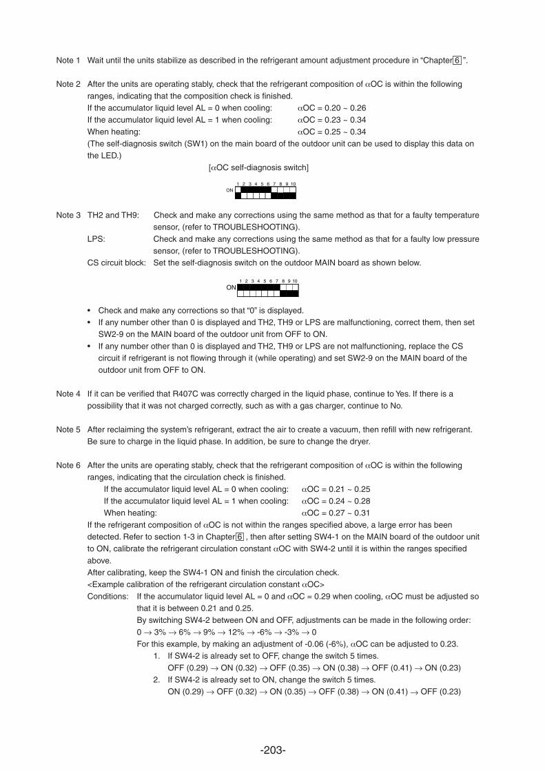
-203-
Note 1 Wait until the units stabilize as described in the refrigerant amount adjustment procedure in “Chapter 6 ”.
Note 2 After the units are operating stably, check that the refrigerant composition of OC is within the following
ranges, indicating that the composition check is finished.If the accumulator liquid level AL = 0 when cooling: OC = 0.20 ~ 0.26If the accumulator liquid level AL = 1 when cooling: OC = 0.23 ~ 0.34
When heating: OC = 0.25 ~ 0.34(The self-diagnosis switch (SW1) on the main board of the outdoor unit can be used to display this data onthe LED.)
[ OC self-diagnosis switch]
Note 3 TH2 and TH9: Check and make any corrections using the same method as that for a faulty temperaturesensor, (refer to TROUBLESHOOTING).
LPS: Check and make any corrections using the same method as that for a faulty low pressuresensor, (refer to TROUBLESHOOTING).
CS circuit block: Set the self-diagnosis switch on the outdoor MAIN board as shown below.
• Check and make any corrections so that “0” is displayed.• If any number other than 0 is displayed and TH2, TH9 or LPS are malfunctioning, correct them, then set
SW2-9 on the MAIN board of the outdoor unit from OFF to ON.
• If any number other than 0 is displayed and TH2, TH9 or LPS are not malfunctioning, replace the CScircuit if refrigerant is not flowing through it (while operating) and set SW2-9 on the MAIN board of theoutdoor unit from OFF to ON.
Note 4 If it can be verified that R407C was correctly charged in the liquid phase, continue to Yes. If there is apossibility that it was not charged correctly, such as with a gas charger, continue to No.
Note 5 After reclaiming the system’s refrigerant, extract the air to create a vacuum, then refill with new refrigerant.Be sure to charge in the liquid phase. In addition, be sure to change the dryer.
Note 6 After the units are operating stably, check that the refrigerant composition of OC is within the followingranges, indicating that the circulation check is finished.
If the accumulator liquid level AL = 0 when cooling: OC = 0.21 ~ 0.25If the accumulator liquid level AL = 1 when cooling: OC = 0.24 ~ 0.28When heating: OC = 0.27 ~ 0.31
If the refrigerant composition of OC is not within the ranges specified above, a large error has beendetected. Refer to section 1-3 in Chapter 6 , then after setting SW4-1 on the MAIN board of the outdoor unitto ON, calibrate the refrigerant circulation constant OC with SW4-2 until it is within the ranges specified
above.After calibrating, keep the SW4-1 ON and finish the circulation check.<Example calibration of the refrigerant circulation constant OC>
Conditions: If the accumulator liquid level AL = 0 and OC = 0.29 when cooling, OC must be adjusted sothat it is between 0.21 and 0.25.By switching SW4-2 between ON and OFF, adjustments can be made in the following order:
0 3% 6% 9% 12% -6% -3% 0For this example, by making an adjustment of -0.06 (-6%), OC can be adjusted to 0.23.
1. If SW4-2 is already set to OFF, change the switch 5 times.
OFF (0.29) ON (0.32) OFF (0.35) ON (0.38) OFF (0.41) ON (0.23)2. If SW4-2 is already set to ON, change the switch 5 times.
ON (0.29) OFF (0.32) ON (0.35) OFF (0.38) ON (0.41) OFF (0.23)
1ON
2 3 4 5 6 7 8 9 10
1 2 3 4 5 6 7 8 9 10
ON


Related Documents