International Journal of Engineering Research and Development e-ISSN: 2278-067X, p-ISSN: 2278-800X, www.ijerd.com Volume 10, Issue 11 (November 2014), PP.06-16 6 Seamless Transitions between Grid-Connected and Stand-Alone Operations of Distributed Generation in Microgrids Irvin J. Balaguer-Álvarez 1 , Uthane Supatti 2 , Jorge G. Cintrón-Rivera 3 , Fang Z. Peng 4 1 University of Puerto Rico-Aguadilla Campus, Aguadilla, Puerto Rico 2 Kasetsart University at Si Racha, Chonburi, Thailand 3 General Motors, Detroit, Michigan, USA 1,4 Michigan State University, East Lansing, Michigan, USA. Abstract:- Control of the Distributed Generation (DG) system is important in both grid-connected and stand- alone modes and the system stability becomes very crucial during the transfer between these two modes. If the system does not have a proper transfer procedure, severe transient voltages or currents will occur, which may damage the entire system. A seamless transfer can ensure smooth operation and quick attainment of steady state. In order to solve these transition problems, this paper presents the development and test of a control strategy for DG capable of working in grid-connected and intentional islanding connection modes with seamless transitions from both operational modes. Keywords:- Distributed generation, grid-connected operation, stand-alone operation, islanding detection, seamless transitions I. INTRODUCTION The current model for electricity generation and distribution in the United States is dominated by centralized power plants. The power at these plants is typically combustion (coal, oil, and natural) or nuclear generated. Centralized power models like this require distribution from the center to outlying consumers. This system of centralized power plants has many disadvantages. Electric utilities are becoming more and more stressed since existing transmission and distribution systems are facing their operating constraints with growing load. Greenhouse gas emissions have resulted in a call for cleaner renewable power sources. Under such circumstances, distributed generation (DG) with alternative sources such as fuel-cell, wind-turbine, bio-mass, micro-turbine and solar-cell systems, has been considered as a promising solution to the above problems [1-3]. DG is defined as small, modular electricity generators located close to the end customer's load connection point. DGs can enable utilities to decrease investment costs in transmission and distribution system upgrades while still meeting increasing power demands. Also, DGs provide customers with improved quality and reliability of energy supplies without imposing undesirable effects on environment [4-5]. In general, DG can be intended as small sized power plants that are designed to be installed and operated within a local load center. Control of the DG system is important in both grid-connected and stand-alone modes and the system stability becomes very crucial during the transfer between these two modes. If the system does not have a proper transfer procedure, severe transient voltages or currents will occur, which may damage the entire system [6]. A seamless transfer can ensure smooth operation and quick attainment of steady state. This paper presents the development and test of a control strategy for DG capable of working in both intentional islanding (stand-alone) and grid-connected modes. The stand-alone control features an output voltage controller capable of loss of main detection and seamless transition from grid-connected to stand-alone operation modes with minimum interruption to the load. The grid-connected mode with current control is also enabled for the case of power grid connection. This grid-connected control features an output current controller capable of synchronization with the grid and re-synchronization for grid reconnection with minimum interruption to the load. The operational principle and control methods of the proposed system are explained in detail. A DG inverter system has been designed, built and set up for testing. Simulation and experimental results are provided in order to verify the validity of the developed DG system. II. SYSTEM DESCRIPTION Fig. 1 shows the proposed main circuit topology for a grid-connected and stand-alone operation voltage source inverter. The system consists of a DG unit that is modelled by a DC source, a sinusoidal pulse-width- modulated (SPWM) voltage source inverter, an LCL filter to achieve attenuation of the switching frequency

Welcome message from author
This document is posted to help you gain knowledge. Please leave a comment to let me know what you think about it! Share it to your friends and learn new things together.
Transcript
International Journal of Engineering Research and Development
e-ISSN: 2278-067X, p-ISSN: 2278-800X, www.ijerd.com
Volume 10, Issue 11 (November 2014), PP.06-16
6
Seamless Transitions between Grid-Connected and Stand-Alone
Operations of Distributed Generation in Microgrids
Irvin J. Balaguer-Álvarez1, Uthane Supatti
2, Jorge G. Cintrón-Rivera
3,
Fang Z. Peng4
1University of Puerto Rico-Aguadilla Campus, Aguadilla, Puerto Rico
2Kasetsart University at Si Racha, Chonburi, Thailand
3General Motors, Detroit, Michigan, USA
1,4Michigan State University, East Lansing, Michigan, USA.
Abstract:- Control of the Distributed Generation (DG) system is important in both grid-connected and stand-
alone modes and the system stability becomes very crucial during the transfer between these two modes. If the
system does not have a proper transfer procedure, severe transient voltages or currents will occur, which may
damage the entire system. A seamless transfer can ensure smooth operation and quick attainment of steady state.
In order to solve these transition problems, this paper presents the development and test of a control strategy for
DG capable of working in grid-connected and intentional islanding connection modes with seamless transitions
from both operational modes.
Keywords:- Distributed generation, grid-connected operation, stand-alone operation, islanding detection,
seamless transitions
I. INTRODUCTION The current model for electricity generation and distribution in the United States is dominated by
centralized power plants. The power at these plants is typically combustion (coal, oil, and natural) or nuclear
generated. Centralized power models like this require distribution from the center to outlying consumers. This
system of centralized power plants has many disadvantages. Electric utilities are becoming more and more
stressed since existing transmission and distribution systems are facing their operating constraints with growing
load. Greenhouse gas emissions have resulted in a call for cleaner renewable power sources. Under such
circumstances, distributed generation (DG) with alternative sources such as fuel-cell, wind-turbine, bio-mass,
micro-turbine and solar-cell systems, has been considered as a promising solution to the above problems [1-3].
DG is defined as small, modular electricity generators located close to the end customer's load
connection point. DGs can enable utilities to decrease investment costs in transmission and distribution system
upgrades while still meeting increasing power demands. Also, DGs provide customers with improved quality
and reliability of energy supplies without imposing undesirable effects on environment [4-5]. In general, DG can
be intended as small sized power plants that are designed to be installed and operated within a local load center.
Control of the DG system is important in both grid-connected and stand-alone modes and the system
stability becomes very crucial during the transfer between these two modes. If the system does not have a proper
transfer procedure, severe transient voltages or currents will occur, which may damage the entire system [6]. A
seamless transfer can ensure smooth operation and quick attainment of steady state.
This paper presents the development and test of a control strategy for DG capable of working in both
intentional islanding (stand-alone) and grid-connected modes. The stand-alone control features an output voltage
controller capable of loss of main detection and seamless transition from grid-connected to stand-alone
operation modes with minimum interruption to the load. The grid-connected mode with current control is also
enabled for the case of power grid connection. This grid-connected control features an output current controller
capable of synchronization with the grid and re-synchronization for grid reconnection with minimum
interruption to the load.
The operational principle and control methods of the proposed system are explained in detail. A DG
inverter system has been designed, built and set up for testing. Simulation and experimental results are provided
in order to verify the validity of the developed DG system.
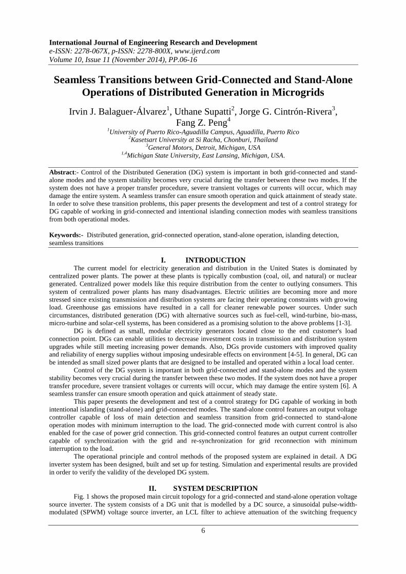
II. SYSTEM DESCRIPTION Fig. 1 shows the proposed main circuit topology for a grid-connected and stand-alone operation voltage
source inverter. The system consists of a DG unit that is modelled by a DC source, a sinusoidal pulse-width-
modulated (SPWM) voltage source inverter, an LCL filter to achieve attenuation of the switching frequency
Seamless Transitions between Grid-Connected and Stand-Alone Operations of Distributed Gener…
7
ripple that causes harmonics in the output voltage [1, 7-10], a parallel load, and the controller needed to
implement grid connected and stand-alone operations with seamless transition between both modes of operation.
The controller includes control for grid-connected and stand-alone operations, PLL, coordinate
transforms, parallel interconnection to the grid (represented by ideal, sinusoidal voltage sources behind line
impedances) through the Point of Common Coupling (PCC) breakers. The loss of main detection, seamless
transition from grid-connected to stand alone, and re-connection to the grid for seamless transition from stand
alone to grid-connected are also included.
IL
fC
dcVa
cb
aS
Grid'aS
bS
'bS
cS
'cS
gL aI
Load
PCC
IaV GaV
CONTROLLER
'a aS
'b bS
'c cS
aIbIcIIaV IbV IcV I abV I bcV I caV G abV G bcV G caV
Voltage Source Inverter LCL Filter
Utility
Disconnect
Switch
Fig. 1: Schematic diagram of the grid-connected inverter system.
III. PROPOSED CONTROL FOR INTENTIONAL ISLANDING OPERATION WITH
SEAMLESS TRANSITION FROM GRID-CONNECTED OPERATION Control of the DG system is important in both grid-connected and stand-alone modes, moreover the
system stability becomes very crucial during the transfer between these two modes. If the system does not have
a proper transfer procedure, severe transient voltages or currents will occur, which may damage the entire
system [6]. A seamless transfer can ensure smooth operation and quick attainment of steady state.
In order to solve this transition problem, this section presents the development and test of a control
strategy for DG capable of working in intentional islanding connection mode with a seamless transition from
grid-connected to stand-alone operation modes. The control scheme proposed is based on a voltage-controlled
method for the stand-alone DG inverter [11-12]. The stand-alone mode with voltage control features a grid
condition detection algorithm to detect the instant at which the DG is cut from the main grid and a controller
with seamless transition from grid-connected to stand-alone operation modes.
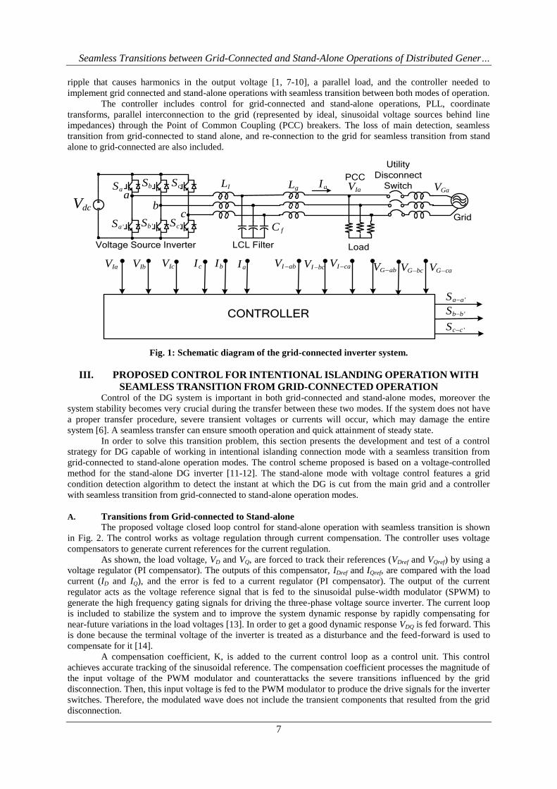
A. Transitions from Grid-connected to Stand-alone
The proposed voltage closed loop control for stand-alone operation with seamless transition is shown
in Fig. 2. The control works as voltage regulation through current compensation. The controller uses voltage
compensators to generate current references for the current regulation.
As shown, the load voltage, VD and VQ, are forced to track their references (VDref and VQref) by using a
voltage regulator (PI compensator). The outputs of this compensator, IDref and IQref, are compared with the load
current (ID and IQ), and the error is fed to a current regulator (PI compensator). The output of the current
regulator acts as the voltage reference signal that is fed to the sinusoidal pulse-width modulator (SPWM) to
generate the high frequency gating signals for driving the three-phase voltage source inverter. The current loop
is included to stabilize the system and to improve the system dynamic response by rapidly compensating for
near-future variations in the load voltages [13]. In order to get a good dynamic response VDQ is fed forward. This
is done because the terminal voltage of the inverter is treated as a disturbance and the feed-forward is used to
compensate for it [14].
A compensation coefficient, K, is added to the current control loop as a control unit. This control
achieves accurate tracking of the sinusoidal reference. The compensation coefficient processes the magnitude of
the input voltage of the PWM modulator and counterattacks the severe transitions influenced by the grid
disconnection. Then, this input voltage is fed to the PWM modulator to produce the drive signals for the inverter
switches. Therefore, the modulated wave does not include the transient components that resulted from the grid
disconnection.
Seamless Transitions between Grid-Connected and Stand-Alone Operations of Distributed Gener…
8
Current
Regulator
VD
VQ
+
++
+IQref
IDref+
+
-
-
DQ
ABC
Da
Db
Dc
SPWMSa-a’
Sb-b’
Sc-c’
Voltage
Regulator
VQref
VDref
+
+
-
-
ABC
VIa
VIb
VIc
I D I Q
I aI c I b
VD V
Q
PLL
Synchronization
controller
ABCDQ
_
_
K
K
new
old
new new
new
V V
Fig. 2: Voltage controlled inverter.
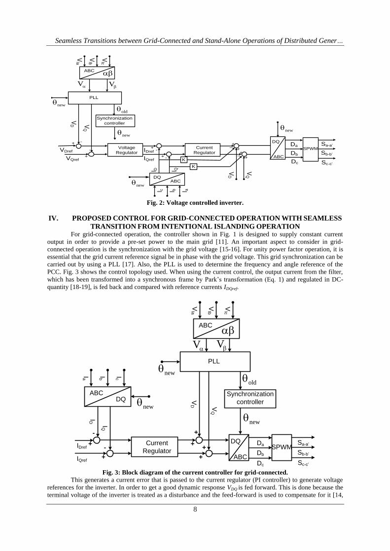
IV. PROPOSED CONTROL FOR GRID-CONNECTED OPERATION WITH SEAMLESS
TRANSITION FROM INTENTIONAL ISLANDING OPERATION For grid-connected operation, the controller shown in Fig. 1 is designed to supply constant current
output in order to provide a pre-set power to the main grid [11]. An important aspect to consider in grid-
connected operation is the synchronization with the grid voltage [15-16]. For unity power factor operation, it is
essential that the grid current reference signal be in phase with the grid voltage. This grid synchronization can be
carried out by using a PLL [17]. Also, the PLL is used to determine the frequency and angle reference of the
PCC. Fig. 3 shows the control topology used. When using the current control, the output current from the filter,
which has been transformed into a synchronous frame by Park’s transformation (Eq. 1) and regulated in DC-
quantity [18-19], is fed back and compared with reference currents IDQref.
ABC
ABCDQ
VIa
VIb
VIc
ID
IQ
PLL
Ia IcIb
VD V
Q
Current
Regulator+
+
+
+
IQref
IDref+
+
-
-DQ
ABC
Da
Db
Dc
SPWMSa-a’
Sb-b’
Sc-c’
Synchronization
controller
old
new
new
new
VV
Fig. 3: Block diagram of the current controller for grid-connected.
This generates a current error that is passed to the current regulator (PI controller) to generate voltage
references for the inverter. In order to get a good dynamic response VDQ is fed forward. This is done because the
terminal voltage of the inverter is treated as a disturbance and the feed-forward is used to compensate for it [14,
Seamless Transitions between Grid-Connected and Stand-Alone Operations of Distributed Gener…
9
18-19]. The voltage references in DC-quantities, VDQref, are transformed into a stationary frame by the inverse of
Park’s transformation (Eq. 2) and utilized as command voltages for generating high frequency pulse width
modulated (PWM) voltages.
cos cos( 2 / 3) cos( 2 / 3)2
sin sin( 2 / 3) sin( 2 / 3)3
1 / 2 1 / 2 1 / 2
0
XXaD
X XQ b
XX c
(1)
cos sin 1 / 2
cos( 2 / 3) sin( 2 / 3) 1 / 2
cos( 2 / 3) sin( 2 / 3) 1 / 2
0
X Xa D
X Xb Q
X Xb
(2)
A. Synchronization Controller for Grid Reconnection: Proposed Algorithm
When the DG is in islanded mode operation and the grid-disconnection cause disappears, the transition
from stand-alone to grid-connected mode can be started [20]. To avoid hard transients in the reconnection, the
DG has to be synchronized with the grid voltage [11, 15-16]. The DG is operated in synchronous island mode
until both systems are synchronized.
Once the voltage in the DG is synchronized with the utility voltage, the DG is reconnected to the grid
and the controller will pass from voltage control mode to current control mode.
This synchronization is achieved by implementing the following algorithm:
o Assume that the phase difference between grid voltage and inverter voltage is given by:
V VG I
(3)
o In order to obtain information of , two sets of voltage values are used:
3
cos( )2
k V V V V V VIa Ga Ib Gb Ic Gc
(4)
3
cos( ) 3sin( )4
g V V V V V VIa Gb Ib Gc Ic Ga
(5)
where,
sin( )V V t
Ga Gm
sin( 120 )oV V tGb Gm
sin( 120 )oV V tGc Gm
sin( )V V tIa Im
sin( 120 )oV V tIb Im
sin( 120 )oV V tIc Im
Using the variables k and g, sin( ) can be found as:
4 2
3 3sin( )3
g k
(6)
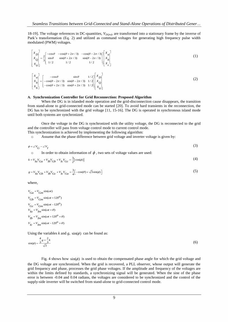
Fig. 4 shows how sin( ) is used to obtain the compensated phase angle for which the grid voltage and
the DG voltage are synchronized. When the grid is recovered, a PLL observer, whose output will generate the
grid frequency and phase, processes the grid phase voltages. If the amplitude and frequency of the voltages are
within the limits defined by standards, a synchronizing signal will be generated. When the sine of the phase
error is between -0.04 and 0.04 radians, the voltages are considered to be synchronized and the control of the
supply-side inverter will be switched from stand-alone to grid-connected control mode.
Seamless Transitions between Grid-Connected and Stand-Alone Operations of Distributed Gener…
10
Fig. 4: Synchronization controller
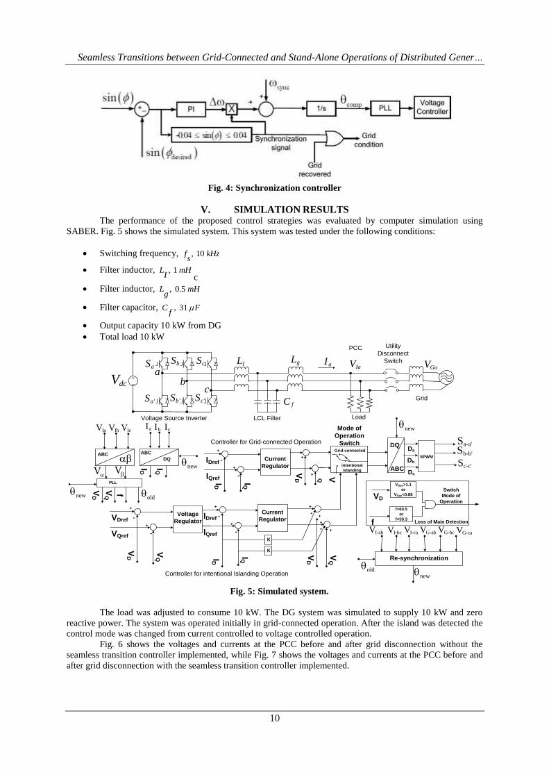
V. SIMULATION RESULTS The performance of the proposed control strategies was evaluated by computer simulation using
SABER. Fig. 5 shows the simulated system. This system was tested under the following conditions:
Switching frequency, , 10 f kHzs
Filter inductor, , 1 L mHI c
Filter inductor, , 0.5 L mHg
Filter capacitor, , 31 C Ff
Output capacity 10 kW from DG
Total load 10 kW
IL
fC
dcVa
cb
aS
Grid'aS
bS
'bS
cS
'cS
gLaI
Load
PCC
IaV GaV
Voltage Source Inverter LCL Filter
Utility
Disconnect
Switch
Loss of Main Detection
VD
f
VDpu>1.1
or
VDpu<0.88
f>60.5
or
f<59.3
Switch
Mode of
Operation
Re-synchronization
I-bcV I-caV G-abV G-bcV G-caV
SPWM
DQ
ABC
Da
Db
Dc
Mode of
Operation
SwitchGrid-connected
intentional
islanding
IQID
IQref
IDref
+
+
-
-
Current
Regulator
VD VQ+
+
Voltage
Regulator
K
IQID
IQref
IDref
+
+
-
-
Current
Regulator
VD
VQ
+
+
K
-
-
+
+
VQ
VD
VQref
VDref
+
+
-
-
ABC
DQ
ID IQ
PLL
VD fVQ
aI bI cIIaV IbV IcV
ABC
c-c'Sb-b'Sa-a'S
I-abV
Controller for Grid-connected Operation
Controller for intentional Islanding Operation
new
new
new
newold
old
VV
Fig. 5: Simulated system.
The load was adjusted to consume 10 kW. The DG system was simulated to supply 10 kW and zero
reactive power. The system was operated initially in grid-connected operation. After the island was detected the
control mode was changed from current controlled to voltage controlled operation.
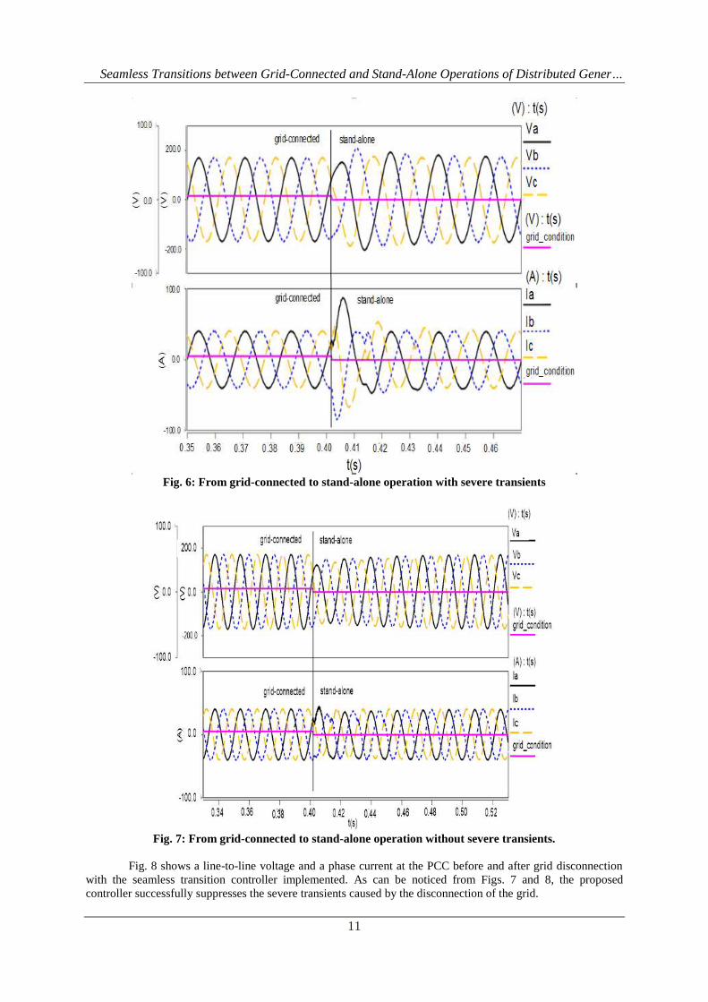
Fig. 6 shows the voltages and currents at the PCC before and after grid disconnection without the
seamless transition controller implemented, while Fig. 7 shows the voltages and currents at the PCC before and
after grid disconnection with the seamless transition controller implemented.
Seamless Transitions between Grid-Connected and Stand-Alone Operations of Distributed Gener…
11
Fig. 6: From grid-connected to stand-alone operation with severe transients
Fig. 7: From grid-connected to stand-alone operation without severe transients.
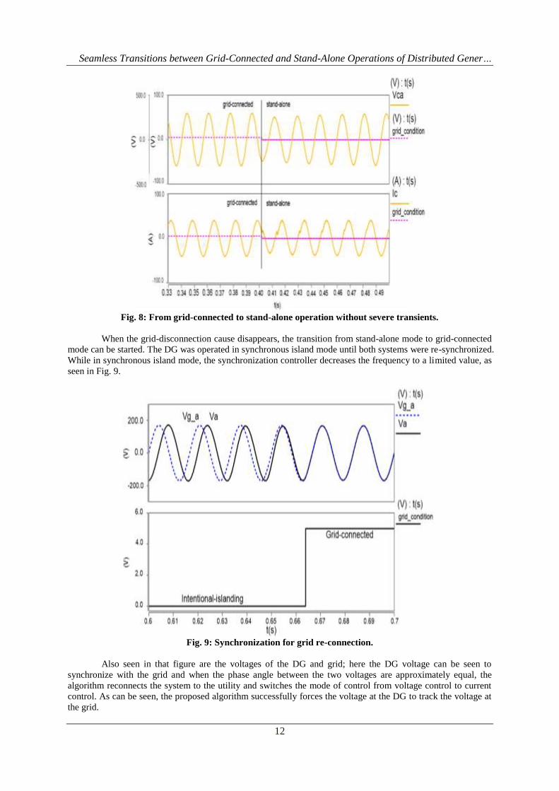
Fig. 8 shows a line-to-line voltage and a phase current at the PCC before and after grid disconnection
with the seamless transition controller implemented. As can be noticed from Figs. 7 and 8, the proposed
controller successfully suppresses the severe transients caused by the disconnection of the grid.
Seamless Transitions between Grid-Connected and Stand-Alone Operations of Distributed Gener…
12
Fig. 8: From grid-connected to stand-alone operation without severe transients.
When the grid-disconnection cause disappears, the transition from stand-alone mode to grid-connected
mode can be started. The DG was operated in synchronous island mode until both systems were re-synchronized.
While in synchronous island mode, the synchronization controller decreases the frequency to a limited value, as
seen in Fig. 9.
Fig. 9: Synchronization for grid re-connection.
Also seen in that figure are the voltages of the DG and grid; here the DG voltage can be seen to
synchronize with the grid and when the phase angle between the two voltages are approximately equal, the
algorithm reconnects the system to the utility and switches the mode of control from voltage control to current
control. As can be seen, the proposed algorithm successfully forces the voltage at the DG to track the voltage at
the grid.
Seamless Transitions between Grid-Connected and Stand-Alone Operations of Distributed Gener…
13
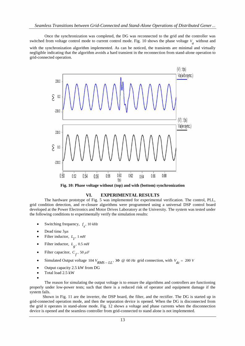
Once the synchronization was completed, the DG was reconnected to the grid and the controller was
switched from voltage control mode to current control mode. Fig. 10 shows the phase voltage Va
without and
with the synchronization algorithm implemented. As can be noticed, the transients are minimal and virtually
negligible indicating that the algorithm avoids a hard transient in the reconnection from stand-alone operation to
grid-connected operation.
Fig. 10: Phase voltage without (top) and with (bottom) synchronization
VI. EXPERIMENTAL RESULTS The hardware prototype of Fig. 5 was implemented for experimental verification. The control, PLL,
grid condition detection, and re-closure algorithms were programmed using a universal DSP control board
developed at the Power Electronics and Motor Drives Laboratory at the University. The system was tested under
the following conditions to experimentally verify the simulation results:
Switching frequency, , 10 f kHzs
Dead time 3μs
Filter inductor, , 1 L mHI
Filter inductor, , 0.5 L mHg
Filter capacitor, , 50 C Ff
Simulated Output voltage 104 , 3 @ 60 V HzRMS LL
grid connection, with 200 V Vdc
Output capacity 2.5 kW from DG
Total load 2.5 kW
The reason for simulating the output voltage is to ensure the algorithms and controllers are functioning
properly under low-power tests; such that there is a reduced risk of operator and equipment damage if the
system fails.
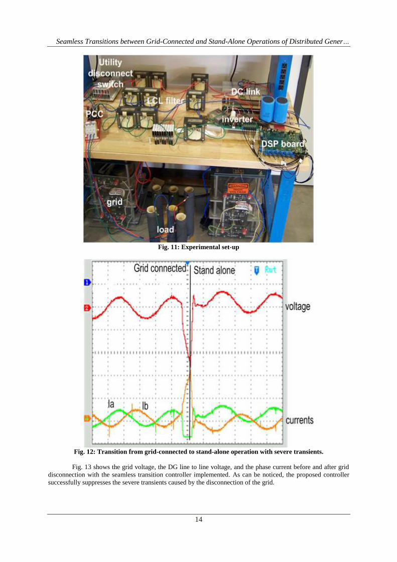
Shown in Fig. 11 are the inverter, the DSP board, the filter, and the rectifier. The DG is started up in
grid-connected operation mode, and then the separation device is opened. When the DG is disconnected from
the grid it operates in stand-alone mode. Fig. 12 shows a voltage and phase currents when the disconnection
device is opened and the seamless controller from grid-connected to stand alone is not implemented.
Seamless Transitions between Grid-Connected and Stand-Alone Operations of Distributed Gener…
14
Fig. 11: Experimental set-up
Fig. 12: Transition from grid-connected to stand-alone operation with severe transients.
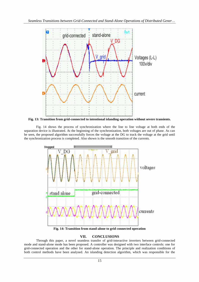
Fig. 13 shows the grid voltage, the DG line to line voltage, and the phase current before and after grid
disconnection with the seamless transition controller implemented. As can be noticed, the proposed controller
successfully suppresses the severe transients caused by the disconnection of the grid.
Seamless Transitions between Grid-Connected and Stand-Alone Operations of Distributed Gener…
15
Fig. 13: Transition from grid-connected to intentional islanding operation without severe transients.
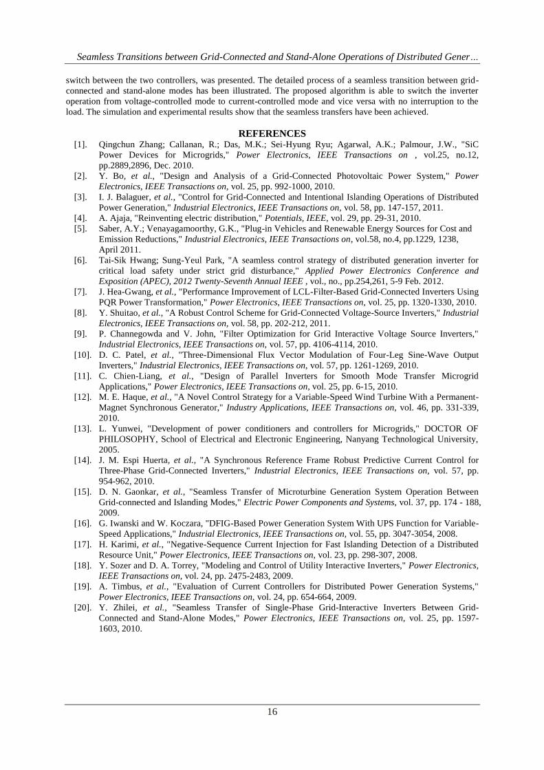
Fig. 14 shows the process of synchronization where the line to line voltage at both ends of the
separation device is illustrated. At the beginning of the synchronization, both voltages are out of phase. As can
be seen, the proposed algorithm successfully forces the voltage at the DG to track the voltage at the grid until
the synchronization process is completed. Also shown is the smooth transition of the currents.
Fig. 14: Transition from stand-alone to grid connected operation
VII. CONCLUSIONS Through this paper, a novel seamless transfer of grid-interactive inverters between grid-connected
mode and stand-alone mode has been proposed. A controller was designed with two interface controls: one for
grid-connected operation and the other for stand-alone operation. The principle and realization conditions of
both control methods have been analysed. An islanding detection algorithm, which was responsible for the
Seamless Transitions between Grid-Connected and Stand-Alone Operations of Distributed Gener…
16
switch between the two controllers, was presented. The detailed process of a seamless transition between grid-
connected and stand-alone modes has been illustrated. The proposed algorithm is able to switch the inverter
operation from voltage-controlled mode to current-controlled mode and vice versa with no interruption to the
load. The simulation and experimental results show that the seamless transfers have been achieved.
REFERENCES [1]. Qingchun Zhang; Callanan, R.; Das, M.K.; Sei-Hyung Ryu; Agarwal, A.K.; Palmour, J.W., "SiC
Power Devices for Microgrids," Power Electronics, IEEE Transactions on , vol.25, no.12,
pp.2889,2896, Dec. 2010.
[2]. Y. Bo, et al., "Design and Analysis of a Grid-Connected Photovoltaic Power System," Power
Electronics, IEEE Transactions on, vol. 25, pp. 992-1000, 2010.
[3]. I. J. Balaguer, et al., "Control for Grid-Connected and Intentional Islanding Operations of Distributed
Power Generation," Industrial Electronics, IEEE Transactions on, vol. 58, pp. 147-157, 2011.
[4]. A. Ajaja, "Reinventing electric distribution," Potentials, IEEE, vol. 29, pp. 29-31, 2010.
[5]. Saber, A.Y.; Venayagamoorthy, G.K., "Plug-in Vehicles and Renewable Energy Sources for Cost and
Emission Reductions," Industrial Electronics, IEEE Transactions on, vol.58, no.4, pp.1229, 1238,
April 2011.
[6]. Tai-Sik Hwang; Sung-Yeul Park, "A seamless control strategy of distributed generation inverter for
critical load safety under strict grid disturbance," Applied Power Electronics Conference and
Exposition (APEC), 2012 Twenty-Seventh Annual IEEE , vol., no., pp.254,261, 5-9 Feb. 2012.
[7]. J. Hea-Gwang, et al., "Performance Improvement of LCL-Filter-Based Grid-Connected Inverters Using
PQR Power Transformation," Power Electronics, IEEE Transactions on, vol. 25, pp. 1320-1330, 2010.
[8]. Y. Shuitao, et al., "A Robust Control Scheme for Grid-Connected Voltage-Source Inverters," Industrial
Electronics, IEEE Transactions on, vol. 58, pp. 202-212, 2011.
[9]. P. Channegowda and V. John, "Filter Optimization for Grid Interactive Voltage Source Inverters,"
Industrial Electronics, IEEE Transactions on, vol. 57, pp. 4106-4114, 2010.
[10]. D. C. Patel, et al., "Three-Dimensional Flux Vector Modulation of Four-Leg Sine-Wave Output
Inverters," Industrial Electronics, IEEE Transactions on, vol. 57, pp. 1261-1269, 2010.
[11]. C. Chien-Liang, et al., "Design of Parallel Inverters for Smooth Mode Transfer Microgrid
Applications," Power Electronics, IEEE Transactions on, vol. 25, pp. 6-15, 2010.
[12]. M. E. Haque, et al., "A Novel Control Strategy for a Variable-Speed Wind Turbine With a Permanent-
Magnet Synchronous Generator," Industry Applications, IEEE Transactions on, vol. 46, pp. 331-339,
2010.
[13]. L. Yunwei, "Development of power conditioners and controllers for Microgrids," DOCTOR OF
PHILOSOPHY, School of Electrical and Electronic Engineering, Nanyang Technological University,
2005.
[14]. J. M. Espi Huerta, et al., "A Synchronous Reference Frame Robust Predictive Current Control for
Three-Phase Grid-Connected Inverters," Industrial Electronics, IEEE Transactions on, vol. 57, pp.
954-962, 2010.
[15]. D. N. Gaonkar, et al., "Seamless Transfer of Microturbine Generation System Operation Between
Grid-connected and Islanding Modes," Electric Power Components and Systems, vol. 37, pp. 174 - 188,
2009.
[16]. G. Iwanski and W. Koczara, "DFIG-Based Power Generation System With UPS Function for Variable-
Speed Applications," Industrial Electronics, IEEE Transactions on, vol. 55, pp. 3047-3054, 2008.
[17]. H. Karimi, et al., "Negative-Sequence Current Injection for Fast Islanding Detection of a Distributed
Resource Unit," Power Electronics, IEEE Transactions on, vol. 23, pp. 298-307, 2008.
[18]. Y. Sozer and D. A. Torrey, "Modeling and Control of Utility Interactive Inverters," Power Electronics,
IEEE Transactions on, vol. 24, pp. 2475-2483, 2009.
[19]. A. Timbus, et al., "Evaluation of Current Controllers for Distributed Power Generation Systems,"
Power Electronics, IEEE Transactions on, vol. 24, pp. 654-664, 2009.
[20]. Y. Zhilei, et al., "Seamless Transfer of Single-Phase Grid-Interactive Inverters Between Grid-
Connected and Stand-Alone Modes," Power Electronics, IEEE Transactions on, vol. 25, pp. 1597-
1603, 2010.
Related Documents