Sealed Lead-Acid Batteries FEATURES Sealed/Maintenance-Free The valve regulated, spill-proof construction of the Power-Sonic battery allows trouble-free, safe operation in any position. There is no need to add electrolyte, as gases generated during over- charge are recombined in a unique “oxygen cycle.” Easy Handling No special handling precautions or shipping containers – surface or air – are required due to leak-proof construction. Economical The high watt-hour per dollar value is made possible by the materials used in a sealed lead-acid battery: they are readily available and low in cost. Long Service Life Under normal operating conditions, four or five years of depend- able service life can be expected in stand-by applications, or between 200 and 1000 charge/ discharge cycles depending on the average depth of discharge. Design Flexibility Batteries may be used in series and/or parallel to obtain choice of voltage and capacity. Due to recent design breakthroughs, the same battery may be used in either cyclic or standby appli- cations. Over 40 models are available to choose from. Rugged Construction The high impact resistant battery case is made either of non- conductive ABS plastic or styrene. Large capacity batteries fre- quently have polypropylene cases. All of these materials impart great resistance to shock, vibration, chemicals and heat. Compact Power-Sonic batteries use state-of-the-art design, high grade materials, and a carefully controlled plate-making process to provide excellent output per cell. The high energy density results in superior power/volume and power/weight ratios. High Discharge Rate Low internal resistance allows discharge currents of up to ten times the rated capacity of the battery. Relatively small batteries may thus be specified in applications requiring high peak currents. Long Shelf Life A low self-discharge rate permits storage of fully charged batteries for up to a year at room temperature before charging is required. Lower storage temperatures enhance shelf life characteristics even further. Wide Operating Temperature Range Power-Sonic batteries may be discharged over a temperature range of -20˚C to +60˚C (-4˚F to +140˚F) and charged at temperatures ranging from -20˚C to +50˚C (-4˚F to +122˚F). Deep Discharge Recovery Special separators, advanced plate composition, and a carefully balanced electrolyte system have greatly improved the ability of recovering from excessively deep discharge.

Welcome message from author
This document is posted to help you gain knowledge. Please leave a comment to let me know what you think about it! Share it to your friends and learn new things together.
Transcript

Sealed Lead-Acid Batteries
FEATURES
Sealed/Maintenance-FreeThe valve regulated, spill-proof construction of the Power-Sonic battery allows trouble-free, safe operation in any position. There is no need to add electrolyte, as gases generated during over-charge are recombined in a unique “oxygen cycle.”
Easy HandlingNo special handling precautions or shipping containers – surface or air – are required due to leak-proof construction.
EconomicalThe high watt-hour per dollar value is made possible by the materials used in a sealed lead-acid battery: they are readily available and low in cost.
Long Service LifeUnder normal operating conditions, four or five years of depend-able service life can be expected in stand-by applications, or between 200 and 1000 charge/ discharge cycles depending on the average depth of discharge.
Design FlexibilityBatteries may be used in series and/or parallel to obtain choice of voltage and capacity. Due to recent design breakthroughs, the same battery may be used in either cyclic or standby appli-cations. Over 40 models are available to choose from.
Rugged ConstructionThe high impact resistant battery case is made either of non-conductive ABS plastic or styrene. Large capacity batteries fre-quently have polypropylene cases. All of these materials impart great resistance to shock, vibration, chemicals and heat.
CompactPower-Sonic batteries use state-of-the-art design, high grade materials, and a carefully controlled plate-making process to provide excellent output per cell. The high energy density results in superior power/volume and power/weight ratios.
High Discharge RateLow internal resistance allows discharge currents of up to ten times the rated capacity of the battery. Relatively small batteries may thus be specified in applications requiring high peak currents.
Long Shelf LifeA low self-discharge rate permits storage of fully charged batteries for up to a year at room temperature before charging is required. Lower storage temperatures enhance shelf life characteristics even further.
Wide Operating Temperature RangePower-Sonic batteries may be discharged over a temperature range of -20˚C to +60˚C (-4˚F to +140˚F) and charged at temperatures ranging from -20˚C to +50˚C (-4˚F to +122˚F).
Deep Discharge RecoverySpecial separators, advanced plate composition, and a carefully balanced electrolyte system have greatly improved the ability of recovering from excessively deep discharge.

SPECIFICATIONSSPECIFICATIONS SEALED LEAD-ACID BATTERIESSEALED LEAD-ACID BATTERIES
ModelNominalVoltage
V
NominalCapacity @
A.H.
Current @20 hr. rate
mA in. mm in. mm in. mm in. mm lbs. kgs.StandardTerminals
WeightHt. Over TerminalHeightWidthLength
The PSG Series of batteries correspond in size to Hawker models of the same voltage and capacity.
UPS High Rate Series
* Watts/cell @ 15 min. rate to 1.67V
PS-260 2 6.0 300 1.97 50 1.34 34 3.94 100 4.13 105 0.90 0.41 F1PS-445 4 4.5 225 1.89 48 2.09 53 3.70 94 3.86 98 1.40 0.64 F2PS-490 4 9.0 450 3.97 101 1.73 44 3.74 95 4.02 102 2.80 1.27 F2PS-4100 4 10.0 500 4.02 102 1.97 50 3.72 94 3.92 100 3.10 1.41 F1PS-605 6 0.5 25 2.24 57 0.55 14 1.97 50 1.97 50 0.20 0.09 WLPS-610 6 1.0 50 2.00 51 1.65 42 2.00 51 2.20 56 0.60 0.27 F1PS-612 6 1.3 65 3.82 97 0.98 24 2.03 51.5 2.25 57 0.70 0.30 F1PS-628 6 2.8 140 2.60 66 1.30 33 3.86 98 4.06 103 1.25 0.57 F1PS-630 6 3.4 170 5.28 134 1.34 34 2.35 60 2.56 65 1.50 0.68 F1PS-632 6 3.2 160 2.60 66 1.30 33 4.65 118 4.92 125 1.50 0.68 F1PS-640 6 4.5 225 2.76 70 1.89 48 4.02 102 4.25 108 1.95 0.89 F1PS-650L 6 5.0 250 2.63 67 2.63 67 3.78 96 4.28 109 2.00 0.91 SPPS-665 6 6.5 325 3.86 98 2.20 56 4.05 103 4.05 103 3.00 1.36 FPPS-670 6 7.0 350 5.95 151 1.34 34 3.70 94 3.86 98 3.00 1.36 F1PS-682 6 8.0 400 3.86 98 2.20 56 4.65 118 4.65 118 3.30 1.50 F1PS-6100 6 12.0 600 5.95 151 2.00 51 3.70 94 3.86 98 4.60 2.09 F1 or F2PS-6120 6 12.0 600 4.26 108 2.75 70 5.54 141 5.54 141 5.20 2.36 FPPS-6120Toy 6 12.0 600 4.26 108 2.75 70 5.54 141 5.54 141 5.20 2.36 TS or THPS-6200 6 20.0 1000 6.18 157 3.27 83 4.92 125 4.92 125 8.20 3.73 NBPS-6360 6 36.0 1800 6.25 159 3.35 85 6.50 165 6.95 177 13.80 6.27 F2 or NBPS-832 8 3.2 160 5.28 134 1.42 36 2.49 63 2.70 69 1.90 0.89 F1PS-1208 12 0.8 40 3.78 96 0.98 25 2.42 62 2.42 62 0.80 0.36 WLPS-1212 12 1.2 60 3.82 97 1.69 43 2.00 51 2.13 54 1.30 0.59 F1PS-1220 12 2.2 110 7.01 178 1.34 34 2.38 60.5 2.56 65 2.10 0.95 F1PS-1223 12 2.3 115 7.17 182 0.94 24 2.42 62 2.42 62 1.76 0.80 PCPS-1228 12 2.8 140 5.24 133 1.30 33 3.82 97 4.09 104 2.55 1.16 F1PS-1229 12 2.9 145 7.01 178 1.34 34 2.36 60 2.56 65 2.20 1.00 F1PS-1230 12 3.4 170 5.28 134 2.64 67 2.36 60 2.60 66 2.60 1.18 F1PS-1250 12 5.0 250 3.54 90 2.75 70 3.98 101 4.17 106 3.75 1.70 F1 or F2PS-1270 12 7.0 350 5.95 151 2.56 65 3.70 94 3.86 98 5.70 2.59 F1 or F2PS-1282 12 8.0 400 3.86 98 4.40 112 4.65 118 4.65 118 6.70 3.05 F1PS-12100 12 12.0 600 5.95 151 4.00 102 3.70 94 3.86 98 9.20 4.18 F1PS-12120 12 12.0 600 5.95 151 3.86 98 3.70 94 3.94 100 9.00 4.09 F2PS-12180 12 18.0 900 7.13 181 2.99 76 6.57 167 6.57 167 13.10 5.95 F2 or NBPS-12260 12 26.0 1300 6.54 166 6.88 175 4.95 126 4.95 126 20.80 9.45 F2 or NBPS-12280 12 28.0 1400 6.54 166 4.95 126 6.89 175 6.89 175 21.40 9.70 NBPS-12330 12 35.0 1750 7.80 198 5.20 132 6.22 158 7.07 180 26.50 12.00 NBPS-12400 12 40.0 2000 7.75 197 6.50 165 6.75 172 6.75 172 32.25 14.70 NBPS-12550 12 55.0 2750 9.04 230 5.45 138 8.15 207 8.98 228 39.20 17.80 NBPS-12750 12 75.0 3750 10.25 260 6.60 168 8.15 207 8.98 228 58.00 26.40 NBPS-121000 12 100.0 5000 12.00 305 6.60 168 8.15 207 8.98 228 67.80 30.80 NBPS-121100 12 110.0 5500 13.00 330 6.76 172 8.40 213 8.70 221 77.70 35.30 BPS-121400 12 140.0 7000 13.60 345 6.82 173 11.28 287 11.34 288 104.50 47.50 B
PSG-450 4 5.0 250 3.54 90 1.94 49 2.87 73 2.87 73 1.70 0.77 F2PSG-480 4 8.0 400 3.54 90 1.94 49 4.00 102 4.00 102 2.50 1.14 F2PSG-625 6 2.5 125 4.15 105 1.63 41 2.70 69 2.70 69 1.50 0.68 F1PSG-650 6 5.0 250 5.28 134 1.94 49 3.00 76 3.00 76 2.50 1.14 F2PSG-680 6 8.0 400 5.28 134 1.94 49 3.99 101 3.99 101 3.70 1.68 F2
PSH-1255 12 5.5 24 Watts/Cell* 3.54 90 2.76 70 3.98 101 4.17 106 4.00 1.80 F2PSH-1280 12 8.0 37 Watts/Cell* 5.95 151 2.56 65 3.70 94 3.86 98 5.95 2.70 F2
FASTON - 0.187" x 0.032"quick disconnect tabs
FASTON - 0.250" x 0.032"quick disconnect tabs
FASTON - PolarizedPositive: "F2", Negative: "F1"
Insulated, stranded wire leads terminated with:Molex Housing 5264-02 & 5263-PBT plug on PS-605
Toy battery connectors:
S-connectoron 6120 TS
H-connectoron 6120 TH
Pressure contacts
Spring terminals for positive
Terminal post with nut & boltconnector
Threaded copper insert terminals
F1
F2
FP
WL
TS/TH
PC
SP
NB
B

.02 .03 .05 .07 .1 .2 .3 .4 .5 .6 .8 1 2 3 4 5 6 8 10 20 30 40 50 60 80 1006
12
18
24
30364254
1
2
3
45679
10
20
30
405060
80
Discharge Current (Amps)
Dis
char
ge T
ime
100
min
hrs
0.5 AH 0.8 AH1.0 AH 1.3 AH2.0 AH 2.3 AH3.0 AH 4.5 AH5 AH
7 AH8 AH
10 AH12 AH 18 AH20 AH
26 AH33 AH 40 AH
55 AH
100 AH
110 AH
140 AH
.15 1.5 15
75 AH
CAPACITY VARIATION BY CURRENT LOAD
DISCHARGE TIME AS FUNCTION OFDISCHARGE CURRENT
The discharge times reflect cut-off voltages which vary with the discharge current:LOAD CURRENT FINAL VOLTAGE
0.05 C 1.75 V/cell0.10 C 1.75 V/cell0.20 C 1.75 V/cell "C" = Capacity of battery0.50 C 1.67 V/cell Example: The 0.5 C current for an 8 A.H.1.00 C 1.50 V/cell battery is 4 A. The 0.1 C current 800 mA.2.00 C 1.50 V/cell3.00 C 1.37 V/cell
2
Ambient temp. 20˚C (68˚F)
When a battery discharges current at a constant rate, its capacity changes according to the amperage load. Capacity increases when the discharge current is less than the 20-hour rate and decreases when the current is higher.
The graph below shows capacity curves for major Power-Sonic battery models with different ampere-hour ratings. Amperage is on the horizontal scale and the time elapsed is on the vertical scale; the product of these values is the capacity.
Proper selection of the battery for a specific application can be made from this graph if the required time and current are known. For example, to determine the proper capacity of a battery providing 3 amps for 20 minutes, locate the intersection of these values on the graph. The curve immediately above that point represents the battery which wil l meet the requirement.

13
12
11
10
9
8
0
6.5
6.0
5.5
5.0
4.5
4.0
1 2 3 5 10 20 30 10 2 3 5 20 30 60min h
Discharge Time @ 0˚C (32˚F)
0.05C0.1C0.175C0.25C
0.6C
1C2C3C
Bat
tery
Vol
tage
(V
)
PERFORMANCE CHARACTERISTICS
CHARGING
APPLICATION NOTES
3
13
12
11
10
9
8
0
6.5
6.0
5.5
5.0
4.5
4.0
1 2 3 5 10 20 30 10 2 3 5 20 30 60min h
Discharge Time @ 20˚C (68˚F)
0.05C0.1C0.175C0.25C
0.6C
1C2C3C
Bat
tery
Vol
tage
(V
)
Characteristic Discharge Curves Characteristic Discharge Curves
Effect of Temperature on Capacity Self-Discharge Characteristics
120
0
Temperature (˚C)
100
80
60
40
20
-20 -10 0 10 20 30 40 50 60
Cap
acity
Rat
io (
%)
0.05C0.1C
0.25C0.6C1C
2C
100
80
60
40
00 2 4 6 8 10 12 14 16 18 20
Storage Period (Months)
Cap
acity
Ret
entio
n R
atio
(%
)
40˚C(104˚F)
Dependable performance and long service life depend upon correct charging. Faulty procedures or inadequate charging equipment result in decreased battery life and/or unsatisfactory performance.
To charge a Power-Sonic battery, a DC voltage higher than the open circuit voltage of 2.15 volts per cell is applied to the terminals of the battery. Any of the con-ventional charging techniques may be used, but to obtain maximum service life and capacity, along with acceptable recharge t ime, constant vol tage - current l imited charging is recommended.
During constant voltage or taper charging, the battery’s current acceptance decreases as voltage and state of charge increase. The battery is fully charged once the current stabilizes at a low level for a few hours.
Cycle Applications: Limit initial current to 0.20C (C is the nominal A.H. capacity of the battery). Charge until battery voltage (under charge) reaches 2.45 volts per cell at 68˚F (20˚C). Hold at 2.45 volts per cell until current drops to approximately 0.01C amperes. Battery is fully charged under these conditions, and charger should either be disconnected or switched to “float” voltage.
“Float” or “Stand-by” Service: Hold battery across constant voltage source of 2.25 to 2.30 volts per cell continuously. When held at this voltage, the battery will seek its own current level and maintain itself in a fully charged condition.
Continuous over- or undercharging is the single worst enemy of a lead-acid battery. Caution should be exercised to insure that the charger is disconnected after cycle charging, or that the float voltage is set correctly.
Because there is a chance of off-gassing hydrogen and oxygen if the battery is overcharged, it is important to prov ide adequate a i r c i rcu lat ion. Never charge or discharge a battery in a hermetically sealed enclosure.
Batteries should not be stored in a discharged state (or in a hot place). If a battery has been discharged for some time it may not readily take a charge. To overcome this, leave the charger connected and the battery should eventually begin to accept a charge.
Due to the self-discharge characteristics of this type of battery, it is imperative that they be charged after 6-9 months of storage, otherwise permanent loss of capacity might occur as a result of sulfation. To prolong shelf life without charging, store batteries at 50˚F (10˚C) or less.
30˚C(86˚F)
20˚C(68˚F)
5˚C(41˚F)
Charg ing i s no t necessary unless 100% of capacity is required.
Charging before use is necessary t o r e c o v e r f u l l capacity.
Charge may fail to r e s t o r e f u l l capacity. Do not let battery reach this state,
FEATURES
1.4
1.3
1.2
1.0
0.90 20 40 60 80 100 120 140
1.12C 1C 0.5C
Charge: 0.1C mA x 15hTemp: 68˚ ±5.4˚F (20˚ ±3˚C)
Duration (minutes)
Vol
tage
(V)
1.4
1.3
1.2
1.0
0.90 2 4 6 8 10 12 14
1.10.1C
Charge: 0.1C mA x 15hTemp: 68˚ ±5.4˚F (20˚ ±3˚C
Duration (h)
Vol
tage
(V
)
0.2C
1.6
1.5
1.4
1.2
1.10 2 4 6 8 10 12 14
1.3
16 18
Charge: 0.1C mA x 15h
32˚F (0˚C)
68˚F (20˚C)
113˚F (45˚C)
Charge Time (h)
Vol
tage
(V) 90
80
70
50
-20 -10 0 10 20 30 40 50
60
60 70
Charge Current: 0.1C mA x 15hTime: 15hrs.Discharge Current:0.2CmAEnd Voltage: 1.0V/cell
Operating Temperature (˚C)
Cap
acity
Ava
ilabl
e
100
Charge CharacteristicsDischarge Characteristics: Std. CellDischarge Characteristics - Hi Temp Cell
Discharge Discharge
Capacity vs Temperature
Discharge Characteristics Discharge Characteristics
Charge Characteristics Temperature Characteristics4
Charge (Standard)
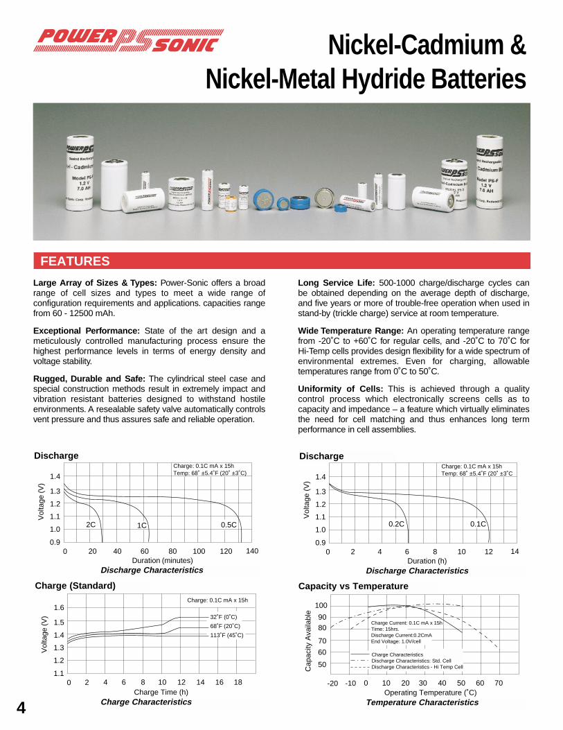
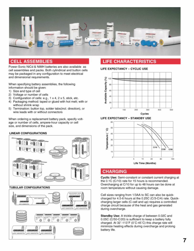
Large Array of Sizes & Types: Power-Sonic offers a broad range of cell sizes and types to meet a wide range of configuration requirements and applications. capacities range from 60 - 12500 mAh.
Exceptional Performance: State of the art design and a meticulously controlled manufacturing process ensure the highest performance levels in terms of energy density and voltage stability.
Rugged, Durable and Safe: The cylindrical steel case and special construction methods result in extremely impact and vibration resistant batteries designed to withstand hostile environments. A resealable safety valve automatically controls vent pressure and thus assures safe and reliable operation.
Long Service Life: 500-1000 charge/discharge cycles can be obtained depending on the average depth of discharge, and five years or more of trouble-free operation when used in stand-by (trickle charge) service at room temperature.
Wide Temperature Range: An operating temperature range from -20˚C to +60˚C for regular cells, and -20˚C to 70˚C for Hi-Temp cells provides design flexibility for a wide spectrum of environmental extremes. Even for charging, allowable temperatures range from 0˚C to 50˚C.
Uniformity of Cells: This is achieved through a quality control process which electronically screens cells as to capacity and impedance – a feature which virtually eliminates the need for cell matching and thus enhances long term performance in cell assemblies.
Nickel-Cadmium &Nickel-Metal Hydride Batteries
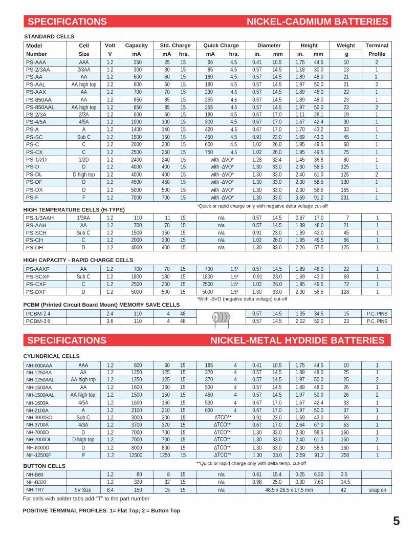
PCBM (Printed Circuit Board Mount) MEMORY SAVE CELLS
CYLINDRICAL CELLS
BUTTON CELLS
HIGH CAPACITY - RAPID CHARGE CELLS
HIGH TEMPERATURE CELLS (H-TYPE)
5
+
+
60BN
K1
5C 1
1POWE
R-SONIC
+
+
60BN
K1
5C 1
1POWE
R-SONIC
+
+
60BN
K1
5C 1
1POWE
R-SONICPCBM-2.4 2.4 110 4 48 0.57 14.5 1.35 34.5 15 P.C. PINS
PCBM-3.6 3.6 110 4 48 0.57 14.5 2.02 52.0 23 P.C. PINS
For cells with solder tabs add "T" to the part number
*Quick or rapid charge only with negative delta voltage cut-off
**Quick or rapid charge only with delta temp. cut-off
*With -∆VO (negative delta voltage) cut-off
Cell
Size
Capacity Std. Charge Quick Charge Diameter Height WeightModel
Number
Volt
V
Terminal
ProfilemA mA hrs. mA hrs. in. mm in. mm g
STANDARD CELLS
SPECIFICATIONS NICKEL-CADMIUM BATTERIES
AAPS-AAXF 1.2 700 70 15 700 1.5* 0.57 14.5 1.89 48.0 22 1 Sub C 1800 1.5*PS-SCXF 1.2 1800 180 15 0.91 23.0 1.69 43.0 60 1
C 2500 1.5*PS-CXF 1.2 2500 250 15 1.02 26.0 1.95 49.5 72 1D 5000 1.5*PS-DXF 1.2 5000 500 15 1.30 33.0 2.30 58.5 1128
PS-AAA 1.2 250 25 15 66 4.5 0.41 10.5 1.75 44.5 10 2AAAPS-2/3AA 1.2 300 30 15 85 4.5 0.57 14.5 1.18 30.0 13 12/3AAPS-AA 1.2 600 60 15 180 4.5 0.57 14.5 1.89 48.0 21 1 AAPS-AAL 1.2 600 60 15 180 4.5 0.57 14.5 1.97 50.0 21 2AA high topPS-AAX 1.2 700 70 15 230 4.5 0.57 14.5 1.89 48.0 22 1AAPS-850AA 1.2 850 85 15 255 4.5 0.57 14.5 1.89 48.0 23 1AAPS-850AAL 1.2 850 85 15 255 4.5 0.57 14.5 1.97 50.0 23 2AA high topPS-2/3A 1.2 600 60 15 180 4.5 0.67 17.0 1.11 28.1 19 12/3APS-4/5A 1.2 1000 100 15 300 4.5 0.67 17.0 1.67 42.4 30 14/5APS-A 1.2 1400 140 15 420 4.5 0.67 17.0 1.70 43.2 33 1APS-SC 1.2 1500 150 15 450 4.5 0.91 23.0 1.69 43.0 45 1Sub CPS-C 1.2 2000 200 15 600 4.5 1.02 26.0 1.95 49.5 68 1CPS-CX 1.2 2500 250 15 750 4.5 1.02 26.0 1.95 49.5 75 1CPS-1/2D 1.21/2D 2400 240 15 with -∆VO* 1.28 32.4 1.45 36.8 80 1
NH-600AAA 1.2 600 60 15 185 4 0.41 10.5 1.75 44.5 10 1AAANH-1250AA 1.2 1250 125 15 370 4 0.57 14.5 1.89 48.0 25 1AANH-1250AAL 1.2 1250 125 15 370 4 0.57 14.5 1.97 50.0 25 2 AA high top
NH-1500AAL 1.2 1500 150 15 450 4 0.57 14.5 1.97 50.0 26 2AA high topNH-1500AA 1.2 1600 160 15 530 4 0.57 14.5 1.89 48.0 26 1AA
NH-1600A 1.2 1600 160 15 530 4 0.67 17.0 1.67 42.4 33 14/5ANH-2100A 1.2 2100 210 15 630 4 0.67 17.0 1.97 50.0 37 1A
POSITIVE TERMINAL PROFILES: 1= Flat Top; 2 = Button Top
SPECIFICATIONS NICKEL-METAL HYDRIDE BATTERIES
PS-D 1.2 4000 400 15 1.30 33.0 2.30 58.5 125 1D with -∆VO*PS-DL 1.2 4000 400 15 1.30 33.0 2.40 61.0 125 2D high top with -∆VO*PS-DF 1.2 4500 450 15 1.30 33.0 2.30 58.5 130 1D with -∆VO*PS-DX 1.2 5000 500 15 1.30 33.0 2.30 58.5 155 1D with -∆VO*PS-F 1.2 7000 700 15 1.30 33.0 3.59 91.2 231 1F with -∆VO*
NH-3000SC 1.2 3000 300 15 0.91 23.0 1.69 43.0 59 1Sub C ∆TCO**NH-3700A 1.2 3700 370 15 0.67 17.0 2.64 67.0 53 14/3A ∆TCO**NH-7000D 1.2 7000 700 15 1.30 33.0 2.30 58.5 160 1D ∆TCO**NH-7000DL 1.2 7000 700 15 1.30 33.0 2.40 61.0 160 2D high top ∆TCO**NH-8000D 1.2 8000 800 15 1.30 33.0 2.30 58.5 160 1D ∆TCO**NH-12500F 1.2F 12500 1250 15 1.30 33.0 3.59 91.2 250 1∆TCO**
PS-1/3AAH 1.2 110 11 15 0.57 14.5 0.67 17.0 7 11/3AA n/aPS-AAH 1.2 700 70 15 0.57 14.5 1.89 48.0 21 1AA n/aPS-SCH 1.2 1500 150 15 0.91 23.0 1.69 43.0 45 1Sub C n/aPS-CH 1.2 2000 200 15 1.02 26.0 1.95 49.5 66 1C n/aPS-DH 1.2 4000 400 15 1.30 33.0 2.26 57.5D 125 1n/a
NH-B80 1.2 80 8 15 0.61 15.4 0.25 6.30 3.5n/aNH-B320 1.2 320 32 15 0.98 25.0 0.30 7.60 14.5n/a
48.5 x 26.5 x 17.5 mmNH-TR7 8.49V Size 150 15 15 42 snap-onn/a
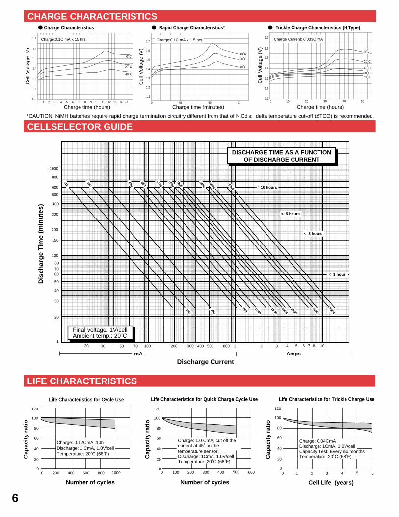
Life Characteristics for Cycle Use
CELLSELECTOR GUIDE
LIFE CHARACTERISTICS
20 30 50 70 100 200 300 400 500 800 1 2 3 4 5 6 8 101
20
30
40
50
6070
200
300
400
500
600
800
1000
Discharge Current
Dis
char
ge
Tim
e (m
inu
tes)
110
100
150
7
150
200
300
600
700
1000
1300
1500
18002200
850
2500
2000
4000
4500
5000
7000
8000
80
mA Amps
< 10 hours
< 5 hours
< 3 hours
< 1 hour
10008006004002000
120
100
80
60
40
20
0
Number of cycles
Cap
acit
y ra
tio
Charge: 0.12CmA, 10hDischarge: 1 CmA, 1.0V/cellTemperature: 20˚C (68˚F)
500400300200100 6000
120
100
80
60
40
20
0
Number of cycles
Cap
acit
y ra
tio
Charge: 1.0 CmA, cut off the current at 45˚ on thetemperature sensor. Discharge: 1CmA, 1.0V/cellTemperature: 20˚C (68˚F)
54321 60
120
100
80
60
40
20
0
Cell Life (years)
Cap
acit
y ra
tio
Charge: 0.04CmADischarge: 1CmA, 1.0V/cellCapacity Test: Every six monthsTemperature: 20˚C (68˚F)
Life Characteristics for Quick Charge Cycle Use Life Characteristics for Trickle Charge Use
6
DISCHARGE TIME AS A FUNCTIONOF DISCHARGE CURRENT
Final voltage: 1V/cellAmbient temp.: 20˚C
CHARGE CHARACTERISTICS
1.11 2 12
Charge time (hours)3 4 5 6 7 8 9 10 11 1513 140
1.2
1.3
1.4
1.5
1.6
1.7
Cell
Volta
ge (
V)
15 hrs.
0˚ C
20˚ C
40˚ C
0 30 60 90
1.1
1.2
1.3
1.4
1.5
1.6
1.7
40˚C
20˚C
10˚C
1.10 10 20 30 40 50
1.2
1.3
1.4
1.5
1.6
1.7
Ce
ll V
olta
ge
(V
)
0˚C
20˚C
40˚C60˚C70˚C
● Charge Characteristics ● Trickle Charge Characteristics (H Type)● Rapid Charge Characteristics*
Charge time (hours)Charge time (minutes)
Charge:0.1C mA x 15 hrs.
Cel
l Vol
tage
(V
)
Cel
l Vol
tage
(V
)
Cel
l Vol
tage
(V
)
Charge:0.1C mA x 1.5 hrs. Charge Current: 0.033C mA
*CAUTION: NiMH batteries require rapid charge termination circuitry different from that of NiCd's: delta temperature cut-off (∆TCO) is recommended.

CHARACTERISTICS
SPECIFICATIONS
SLA Battery Chargers
8
FEATURES
Output Voltage (V) Output Current (A) Dimensions (in.) WeightModel TypeNominal Range Nominal Maximum Length Width Height (lbs.)
PSC-6250F 6 6.83 .30 .40 Fixed volt. float 2.20 1.96 1.88 0.5PSC-6250APSC-6300APSC-6500APSC-61000APSC-64000APSC-12250FPSC-12250APSC-12300APSC-12500FPSC-12500APSC-12800APSC-122000APSC-124000APSC-124000APPSC-12-10APSC-241000A
6 6.75/7.35 .30 .40 Dual volt. auto. 2.20 1.96 1.88 0.56 6.84/7.35 .30 .30 Dual volt. auto. 2.75 2.75 3.75 1.366 6.75/7.35 .60 .75 Dual volt. auto. 2.55 1.88 2.89 0.86 6.84/7.35 1.00 1.00 Dual volt. auto. 2.75 2.75 3.75 1.366 6.75/7.35 3.50 4.00 Dual volt. auto. 5.70 5.80 3.30 6.012 13.65 .25 .40 Fixed volt. float 2.20 1.96 1.88 0.512 13.50/14.70 .25 .40 Dual volt. auto. 2.20 1.96 1.88 0.512 13.68/14.70 .30 .30 Dual volt. auto. 2.75 2.75 3.75 1.3612 13.65 .50 .60 Fixed volt. float 2.55 1.88 2.89 0.812 13.50/14.70 .50 .60 Dual volt. auto. 2.55 1.88 2.89 0.812 13.68/14.70 .80 .80 Dual volt. auto. 2.75 2.75 3.75 1.3612 13.50/14.70 2.00 2.00 Dual volt. auto. 5.55 3.60 2.90 3.812 13.50/14.70 4.00 4.75 Dual volt. auto. 6.65 5.30 3.40 7.412 13.50/14.70 4.00 3.50/2.50 Charger/Power Supply 6.65 5.30 3.40 7.412 13.50/14.70 10.00 10.00 Dual volt. auto. 7.95 6.10 4.50 9.024 27.00/29.40 1.00 1.00 Dual volt. auto. 5.55 3.60 2.90 3.8
Electronically regulated - current limited chargers for sealed lead-acid type batteries.
Wall mount plug-in design for 250, 300, 500, 800 series and 61000A; counter top design for 241000A, 2000, 4000 and 10A series.
Operating temperature range: 32˚F – 104˚F (0˚C – 40˚C).
Input voltage: 110/120 VAC, 60Hz. PSC-122000Aand PSC-241000A can be switched to accept 220/230 VAC, 50Hz.
LED’s: Fo r 250A & 500A ser ies : “POWER ON ” and “CHARGING MODE” (ON=high-rate charging, OFF=float charging). For 300, 800, 1000, & 10A series: “FLOAT” and “FAST CHARGE” indicators. For 2000A, 241000A and 4000 series: single tri-color indicator.
Hi-impact resistant thermo-plastic housing for 250, 300, 500, and 800 series; metal housing for 1000, 2000, 4000, and 10A series.
Screw-type terminals for 250 & 500 series, I/O cord with battery connectors for 300, 800, 1000, 2000, 4000 and 10A series chargers.
“F” Series: Float chargers are designed to provide optimum life for batteries used in standby applications where charging is continuous. The chargers deliver a constant voltage of 2.25 to 2.30 volts per cell which allow the battery to seek its own current level and maintain itself in a fully charged condition. This series is best suited for burglar and fire alarm equipment, emergency lighting, memory protection, or UPS systems where the battery serves as back-up power to the AC source.
“A” Series: Automatic dual rate chargers sense battery requirements and automatically switch from the fast charge to float mode, or vice versa. LED’s provide visual indication of the charging mode. Automatic chargers combine the advantages of float and cycle chargers; recharge time is short yet batteries are safe from being overcharged. This charger is ideal for cyclic applications where recharge time is critical and the battery may be left on charge indefinitely. As a result charging is fool-proof.

SLA CHARGER SELECTION GUIDE
NiCd / NiMH Chargers
Input voltage range: 110 to 120 VAC, 60 Hz.
Operating temperature: 0 ̊to 40˚C (32 ̊to 104˚F)
Dimensions: 2.8”W x 3.8”H x 2.8”D
Weight: Approximately 1.5 lbs.
Charger Max Output Use With Battery U.L./CSAModel mA Voltage Capacity Listing
PSC-6250F 400 6V 1-5 AH U.L.PSC-6250A 400 6V 1-5 AH U.L.
PSC-6500A 500 6V 2-10 AH U.L.
PSC-64000A 4000 6V 20-40 AH - - -PSC-12250F 375 12V 1-5 AH U.L.PSC-12250A 275 12V 1-5 AH U.L.
PSC-12500F 600 12V 2-10 AH U.L.PSC-12500A 500 12V 2-10 AH U.L.PSC-12800A 800 12V 4-12 AH CSA/NRTL*
PSC-12300A 300 12V 1-5 AH CSA/NRTL*
PSC-61000A 1000 6V 4.5-12 AH CSA/NRTL*
PSC-6300A 300 6V 1-5 AH CSA/NRTL*
PSC-122000A** 2000 12V 10-20 AH CSA
PSC-124000A** 4000 12V 17-40 AH CSAPSC-124000AP*** 3500 12V 17-40 AH CSAPSC-12-10** 10000 12V 60-100 AH - - -
PSC-241000A** 1000 24V 5-15 AH CSA
PSN-SERIES FEATURES
PSN-SERIES SPECIFICATIONS
.
Electronically-regulated, current-limited 2-stage chargers for nickel cadmium and nickel metal-hydride batteries.
Timed C/10 charge rate with automatic switching to C/40 trickle rate after fourteen hours to keep the battery fully charged. LED’s indicate charge mode.
Units are calibrated to the battery pack’s specifications based on the number and mAh capacity of the cells. Assemblies of 1-12 cells and capacities of 500-5000 mAh can be charged in about 14 hours.
The wall mount design chargers are shipped with a 6-foot 18-AWG output cable with 2.5mm ID barrel plug connector and feature a vented housing made of tough ABS plastic.
To order, indicate number and capacity (mAh) of cells. Example: 5 cells (6 volt) - 1400 mAh.
Caution: Chargers are not protected against reverse polarityconnectionn. Reversing polarity or shorting will damage thebattery and the charger.
Notes: Recharge time depends on the depth of the preceding discharge and the output current of the charger. To determine the approximate recharge time of a fully discharged battery, divide the battery’s amp. hrs. by the rated output current of the charger and multiply the resulting number of hours by a factor of 1.75 to compensate for the declining output current during the charge cycle. If the amount of amp. hrs. discharged from the battery is known, use it instead of the battery ’s capacity to make the calculation.
* The “NRTL/C” mark appearing next to the CSA stamp indicates that the charger was also tested to meet U.L. requirements (UL 1310). Under the provisions of this agreement, CSA and U.L. can now test to each others’ spec i f ica t ions and thus obta in approva l fo r both organizations.
** PSC-122000A, PSC-241000A and PSC-124000A can be switched to accept 115 VAC or 230 VAC input (47-63 Hz) allowing usage both here and abroad.
*** PSC-124000AP should be used when the automatic dual rate charger is used like a power supply. As such it can supply a continuous load current of up to 2.5A, yet still switch into float mode (13.8V) when the battery is fully charged.
Related Documents