HES-1” HEAT EXCHANGER SIDEWALLS 6U SEALED FOUR HEAT EXCHANGER 1” PITCH ATR ENCLOSURE » Designed expressly for high wattage conduction-cooled VPX applications » Increased thermal performance with respect to CM 0.8” pitch HES » Available in 5 or 7 slot versions for conduction-cooled modules » Forced-air heat exchanger sidewalls, top cover & rear panel » Oversized heat exchangers with low airflow resistance » Extensive variety of military power supply options » Very high airflow dual PX3 military rear fans » Dry air contaminant-free applications » Improved internal forced-air recirculation 1” 5 7

Welcome message from author
This document is posted to help you gain knowledge. Please leave a comment to let me know what you think about it! Share it to your friends and learn new things together.
Transcript

HES-1”Heat excHanger SidewallS
6U
Sealed four Heat excHanger 1” pitcH atr encloSure
» Designed expressly for high wattage conduction-cooled VPX applications » Increased thermal performance with respect to CM 0.8” pitch HES » Available in 5 or 7 slot versions for conduction-cooled modules » Forced-air heat exchanger sidewalls, top cover & rear panel » Oversized heat exchangers with low airflow resistance » Extensive variety of military power supply options » Very high airflow dual PX3 military rear fans » Dry air contaminant-free applications » Improved internal forced-air recirculation
1”
5 7
CM COMPUTER MILITARY COTS TECHNOLOGIES
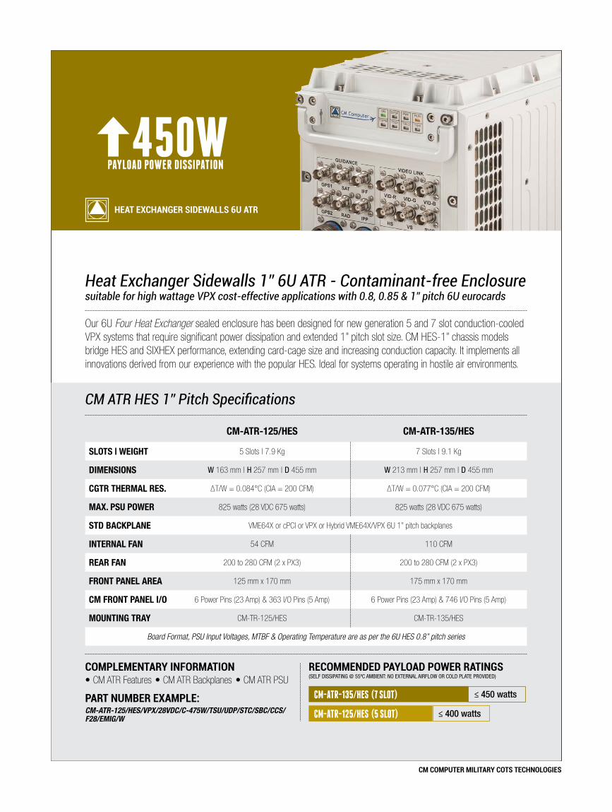
Heat Exchanger Sidewalls 1” 6U ATR - Contaminant-free Enclosuresuitable for high wattage VPX cost-effective applications with 0.8, 0.85 & 1” pitch 6U eurocards
Our 6U Four Heat Exchanger sealed enclosure has been designed for new generation 5 and 7 slot conduction-cooled VPX systems that require significant power dissipation and extended 1” pitch slot size. CM HES-1” chassis models bridge HES and SIXHEX performance, extending card-cage size and increasing conduction capacity. It implements all innovations derived from our experience with the popular HES. Ideal for systems operating in hostile air environments.
450WPAYLOAD POWER DISSIPATION
Heat excHanger sidewalls 6U atr
CM ATR HES 1” Pitch Specifications
complementary information
part nUmber example:CM-ATR-125/HES/VPX/28VDC/C-475W/TSU/UDP/STC/SBC/CCS/F28/EMIG/W
recommended payload power ratings(SELF DISSIPATING @ 55ºC AmbIENT: No ExTErNAL AIrFLow or CoLD PLATE ProvIDED)
CM-ATR-135/HES (7 SLOT) ≤ 450 watts
≤ 400 wattsCM-ATR-125/HES (5 SLOT)
CM-ATR-125/HES CM-ATR-135/HES
SLOTS | WEIGHT 5 Slots | 7.9 Kg 7 Slots | 9.1 Kg
DIMENSIONS w 163 mm | H 257 mm | D 455 mm w 213 mm | H 257 mm | D 455 mm
CGTR THERMAL RES. ΔT/W = 0.084°C (CIA = 200 CFM) ΔT/W = 0.077°C (CIA = 200 CFM)
MAX. PSU POWER 825 watts (28 VDC 675 watts) 825 watts (28 VDC 675 watts)
STD BACKPLANE VME64X or cPCI or VPX or Hybrid VME64X/VPX 6U 1” pitch backplanes
INTERNAL FAN 54 CFM 110 CFM
REAR FAN 200 to 280 CFM (2 x PX3) 200 to 280 CFM (2 x PX3)
FRONT PANEL AREA 125 mm x 170 mm 175 mm x 170 mm
CM FRONT PANEL I/O 6 Power Pins (23 Amp) & 363 I/O Pins (5 Amp) 6 Power Pins (23 Amp) & 746 I/O Pins (5 Amp)
MOUNTING TRAY CM-TR-125/HES CM-TR-135/HES
Board Format, PSU Input Voltages, MTBF & Operating Temperature are as per the 6U HES 0.8” pitch series
•CM ATR Features •CM ATR Backplanes •CM ATR PSU

CM COMPUTER MILITARY COTS TECHNOLOGIES
Minutes 10 20 30 40 50 60
Tem
per
atur
e (°
C)
Chassis Delta-T vs Payload Power & Military Ambient Temperature Range
120
100
80
60
40
20
0
-20
-40ºC
-60
85ºC
55ºC
Ove
rhea
ted
MILITARY LOW AMBIENT TEMPERATURE LIMIT
MILITARY HIGH AMBIENT TEMPERATURE LIMIT
CARD-CAGE HEATERS ON - FANS OFF
TSU SYSTEM SHUTDOWN OR BATTLE SHORT OVERRIDE
Del
ta-T
Ran
ge
Mili
tary
Sys
tem
s A
mb
ient
Op
erat
ing
Tem
p. R
ang
eS
tand
by
PAY
LOA
D M
TBF
DE
CR
EA
SE
SIN
CR
EA
SE
S
MAX ∆T = 30ºC(MIL-STD)
PAYLAOD UNDER TEMPERATURE ZONE
PAYLOAD OVER TEMPERATURE ZONE
STANDARD LABORATORY TESTING AMBIENT TEMPERATURE
PAYLOAD CARD-RAIL LIMIT
maximUm military SyStem delta-tMaximum conduction-cooled payload card-rail temperature is typically 85ºC. To comply with MIL-STD-810, systems must be operational up to 55ºC ambient (worst case scenario).
In theory, this restricts payload maximum ΔT to 85ºC - 55ºC (ΔTmax = 30ºC). Temperatures in excess of 85ºC dramatically increase the risk of module failure and reduce component MTBF. Military limits may be relaxed for systems serving in ‘indoor environments’ (e.g. to 40ºC ambient). Under these conditions ΔT margin can be increased to 85ºC - 40ºC = 45ºC ΔTmax.
cm atr cHaSSiS tHermal teSting
6U HES-1 Military ATR Chassis Performancedesigned for high wattage, 1” pitch - sealed applications
R
J1
GND
J2 J4
J5 J6 J7 J8
J9 J10 J11 J12
J13J14
Remove connector J14before attempting
maintenance
DANGE
28VDC
J350W
50W
50W
50W
50W
[1]
[2]
[3]
[4]
[5]
T4
T5
T3
T2
T1
T-room: 20ºC P-room: 1atm
capabilitieS• Contaminant-free enclosure• Available in ½ ATR, ¾ ATR versions• VPX ready (1.0” Pitch)• Accepts Conduction & Air-cooled 6U Modules• Flexible Top & Bottom I/O wiring• In-line EMI/EMC MIL-STD-461F Filter• Up to 354 watts Total Payload Power @ 30ºC Delta-T*• Integrated Temperature Supervisory Unit (TSU)• 4 Integrated Heat Exchangers• Integrated Rear fan guards• Maintenance free operation• Front panel user indicators• Stand alone low weight ATR• Internal card-cage airflow recirculation• Independent Fan & Power Supply input voltage• Military Operating Temperature (-40°C | +85°C)• Customizable to specific requirements• Low Profile Mounting Tray with quick release• Manufactured with US MIL components
VERSIONS cgtr cptrCM-ATR-125/HES : 0.084ºC/W 0.0924ºC/W
CM-ATR-135/HES : 0.077ºC/W 0.0847ºC/W

CM COMPUTER MILITARY COTS TECHNOLOGIES
cm atr cHaSSiS tHermal teSting
Minutes0 10 20 30 40 50 60
Tem
per
atur
e (°
C)
1/2 ATR Sealed Chassis (5 slot)CM-ATR-125/HES
CGTR = 0.084ºC/W CPTR = 0.0924ºC/W
(Room Temp.)
500W
300W
100W
600W
200W
70
60
50
85
80
40
30
20
10
TCEP = 773W TPP = 703W
Self-dissipation Military Chassis Figures Total Payoad Power vs Board Card-rail Temperature
400W
892W
811W
Ambient Operating Conditions
Tem
per
atur
e (°
C)
CM-ATR-125/HES (5 Slot - 6U ATR - 1” Pitch) Power Dissipation vs Ambient Temperature
70
60
50
40
30
20
10
85
357W
MAX CARD-RAIL TEMP.
85ºC
PERFORMANCE
Performance estimates are given for compliance with the Military Operating Temperature Range. Power Dissipation rates are approximate and provided in
good faith but are not guaranteed for any particular chassis. System operational variables can adversely affect CM ATR
thermal performance such as:
• Installed AC or DC PSUs• Selected Fan Pack• Air Density & Atmospheric Pressure• Payload Distribution in Card-cage• Extreme Ambient Temperatures, etc.
80
324W
773W
703W
CPTR COEFFICIENT
∆T/W = 0.0924C
CGTR COEFFICIENT
∆T/W = 0.084ºC
+55º
C M
ILIT
AR
Y R
AN
GE
Ambient Air Temperature Total Chassis Electrical Power (TCEP) Total Payload Power (TPP)
6U HES-1 Military ATR Chassis Performancedesigned for high wattage, 1” pitch - sealed applications
R
J1
GND
J2 J4
J5 J6 J7 J8
J9 J10 J11 J12
J13J14
Remove connector J14before attempting
maintenance
DANGE
28VDC
J350W
50W
50W
50W
50W
[1]
[2]
[3]
[4]
[5]
T4
T5
T3
T2
T1
T-room: 20ºC P-room: 1atm
Minutes0 10 20 30 40 50 60
Tem
per
atur
e (°
C)
3/4 ATR Sealed Chassis (7 slot)CM-ATR-135/HES
CGTR = 0.077ºC/W CPTR = 0.0847ºC/W
(Room Temp.)
500W
300W
100W
600W
700W
200W
70
60
50
85
80
40
30
20
10
TCEP= 844W TPP = 767W
Self-dissipation Military Chassis Figures Total Payoad Power vs Board Card-rail Temperature
400W
974W
885W
Ambient Operating Conditions
Tem
per
atur
e (°
C)
CM-ATR-135/HES (7 Slot - 6U ATR - 1” Pitch) Power Dissipation vs Ambient Temperature
70
60
50
40
30
20
10
85
389W
MAX CARD-RAIL TEMP.
85ºC
PERFORMANCE
Performance estimates are given for compliance with the Military Operating Temperature Range. Power Dissipation rates are approximate and provided in
good faith but are not guaranteed for any particular chassis. System operational variables can adversely affect CM ATR
thermal performance such as:
• Installed AC or DC PSUs• Selected Fan Pack• Air Density & Atmospheric Pressure• Payload Distribution in Card-cage• Extreme Ambient Temperatures, etc.
80
354W
844W
767W
CPTR COEFFICIENT
∆T/W = 0.0847ºC
CGTR COEFFICIENT
∆T/W = 0.077ºC
+55º
C M
ILIT
AR
Y R
AN
GE
Ambient Air Temperature Total Chassis Electrical Power (TCEP) Total Payload Power (TPP)

CM COMPUTER MILITARY COTS TECHNOLOGIES
/S5 COTS Enclosure Size/ModelCM-ATR-25: 5 Slot 6U Enclosure (0.8” pitch - 1/2 ATR type)CM-ATR-125: 5 Slot 6U Enclosure (1” pitch - 1/2 ATR type)CM-ATR-35: 7 Slot 6U Enclosure (0.8” pitch - 3/4 ATR type)CM-ATR-135: 7 Slot 6U Enclosure (1” pitch - 3/4 ATR type)CM-ATR-45: 12 Slot 6U Enclosure (0.8” pitch - 1 ATR type)
/CT Enclosure Cooling TechniqueS: Standard Sealed (0.8” pitch)SEF: Sealed with Extended Fins (0.8” pitch)SEF-HP: Sealed with Extended Fins + 18/20 Heat Pipes (0.8” pitch)HES: Sealed with 4 Heat Exchangers (0.8” and 1” pitch versions)SIXHEX: Sealed with 6 Heat Exchangers (0.8” and 1” pitch versions)SIXHEX-HP: Sealed with 6 Heat Exchangers and integrated Heat Pipes (0.8” pitch with 16HP and 1” pitch with 20HP versions)FAC: Flowthrough Air Cooled Enclosure (open, non-sealed) (0.8” pitch)
/B Backplane Type (slot pitch according to chassis model)VME64x: Military VME64x BackplanecPCI: Military Compact PCI BackplaneVPX: VITA 46 Military VPX BackplaneVME64x/VPX: Hybrid VME64x mixed with VPX Military BackplaneVME64x/cPCI: Hybrid VME64x mixed with cPCI Military BackplaneNote: Hybrid dual bus backplanes are available for a limited set of chassis only
/I PSU Input Power Voltage28VDC: 28 VDC Input48VDC: 48 VDC Input72VDC: 72 VDC Input270VDC: 270 VDC Input90-264VAC: Autorange 90-264 VAC @ 47-880 Hz Input200VAC-3PH: 200 VAC 3 Phase @ 47-880 Hz Input
/W Power Supply Unit WattsAll PSUs = All PSUs except 28 VDC input | 28 VDC = 28 VDC input only
PSUs for CM-ATR-25 (5 slot)
Models: /S or /SEF or /SEF-HP or /HES (0.8”) or /FAC300W: 28 VDC (+5 VDC @ 20A, +3.3 VDC @ 5A, ±12 VDC @ 8A)
400W: All PSUs (+5 VDC @ 20A, +3.3 VDC @ 5A, ±12 VDC @ 12A)
Models: /S or /SEF or /SEF-HP or /HES or /SIXHEX or /SIXHEX-HP A-475W: 28 VDC (+5 VDC @ 40A, +3.3 VDC @ 22A, ±12 VDC @ 8A)
A-575W: All PSUs (+5 VDC @ 40A, +3.3 VDC @ 22A, ±12 VDC @ 12A)
B-450W: 28 VDC (+5 VDC @ 20A, +3.3 VDC @ 45A, ±12 VDC @ 8A)
B-550W: All PSUs (+5 VDC @ 20A, +3.3 VDC @ 45A, ±12 VDC @ 12A)
C-475W: 28 VDC (+5 VDC @ 20A, +3.3 VDC @ 22A, +12 VDC @ 16A,-12 VDC @ 8A)
C-575W: All PSUs (+5 VDC @ 20A, +3.3 VDC @ 22A, +12 VDC @ 21A, -12 VDC @ 12A)
PSUs for CM-ATR-(1)35 (7 slot) & CM-ATR-125 (5 Slot 1” Pitch)Models: /S or /SEF or /SEF-HP or /HES (0.8”) or /FAC400W: 28 VDC (+5 VDC @ 40A, +3.3 VDC @ 5A, ±12 VDC @ 8A)
500W: All PSUs (+5 VDC @ 40A, +3.3 VDC @ 5A, ±12 VDC @ 12A)
Models: /S or /SEF or /SEF-HP or /HES or /SIXHEX or /SIXHEX-HP A-475W: 28 VDC (+5 VDC @ 40A, +3.3 VDC @ 22A, ±12 VDC @ 8A)
A-575W: All PSUs (+5 VDC @ 40A, +3.3 VDC @ 22A, ±12 VDC @ 12A)
A-675W: 28 VDC (+5 VDC @ 80A, +3.3 VDC @ 22A, ±12 VDC @ 8A)
A-775W: All PSUs (+5 VDC @ 80A, +3.3 VDC @ 22A, ±12 VDC @ 12A)
B-450W: 28 VDC (+5 VDC @ 20A, +3.3 VDC @ 45A, ±12 VDC @ 8A)
B-550W: All PSUs (+5 VDC @ 20A, +3.3 VDC @ 45A, ±12 VDC @ 12A)
B-564W: 28 VDC (+5 VDC @ 20A, +3.3 VDC @ 80A, ±12 VDC @ 8A)
B-664W: All PSUs (+5 VDC @ 20A, +3.3 VDC @ 80A, ±12 VDC @ 12A)
C-475W: 28 VDC (+5 VDC @ 20A, +3.3 VDC @ 22A, +12 VDC @ 16A,-12 VDC @ 8A)
C-575W: All PSUs (+5 VDC @ 20A, +3.3 VDC @ 22A, +12 VDC @ 21A, -12 VDC @ 12A)
C-775W: 28 VDC (+5 VDC @ 20A, +3.3 VDC @ 22A, +12 VDC @ 41A, -12 VDC @ 8A)
C-825W: All PSUs (+5 VDC @ 20A, +3.3 VDC @ 22A, +12 VDC @ 41A, -12 VDC @ 12A)
D-550W: 28 VDC (+5 VDC @ 40A, +3.3 VDC @ 45A, ±12 VDC @ 8A)
D-650W: All PSUs (+5 VDC @ 40A, +3.3 VDC @ 45A, ±12 VDC @ 12A)
E-550W: 28 VDC (+5 VDC @ 20A, +3.3 VDC @ 45A, +12 VDC @ 16A, -12 VDC @ 8A)
E-650W: All PSUs (+5 VDC @ 20A, +3.3 VDC @ 45A, +12 VDC @ 21A, -12 VDC @ 12A)
F-575W: 28 VDC (+5 VDC @ 40A, +3.3 VDC @ 22A, +12 VDC @ 16A,-12 VDC @ 8A)
F-675W: All PSUs (+5 VDC @ 40A, +3.3 VDC @ 22A, +12 VDC @ 21A, -12 VDC @ 12A)
Dual-redundant PSUs for /HES or /SIXHEX or /SIXHEX-HP modelsR2x500W: (+5 VDC @ 25A, +3.3 VDC @ 23A, ±12 VDC @ 12A)
PSU for CM-ATR-45 (12 slot)Models: /S or /SEF or /SEF-HP or /HES (0.8”) or /FAC950W: 28 VDC (+5 VDC @ 80A, +3.3 VDC @ 45A, ±12 VDC @ 16A)
1050W: All PSUs (+5 VDC @ 80A, +3.3 VDC @ 45A, ±12 VDC @ 21A)
Models: /HES or /SIXHEX or /SIXHEX-HP A-950W: 28 VDC (+5 VDC @ 80A, +3.3 VDC @ 45A, ±12 VDC @ 16A)
A-1050W: All PSUs (+5 VDC @ 80A, +3.3 VDC @ 45A, ±12 VDC @ 21A)
B-950W: 28 VDC (+5 VDC @ 40A, +3.3 VDC @ 45A, +12 VDC @ 33A, -12 VDC @ 16A)
B-1100W: All PSUs (+5 VDC @ 40A, +3.3 VDC @ 45A, +12 VDC @ 41A, -12 VDC @ 20A)
B-1065W: 28 VDC (+5 VDC @ 80A, +3.3 VDC @ 80A, ±12 VDC @ 16A)
B-1165W: All PSUs (+5 VDC @ 80A, +3.3 VDC @ 80A, ±12 VDC @ 21A)
C-864W: 28 VDC (+5 VDC @ 40A, +3.3 VDC @ 80A, ±12 VDC @ 16A)
C-964W: All PSUs (+5 VDC @ 40A, +3.3 VDC @ 80A, ±12 VDC @ 20A)
C-1225W: 28 VDC (+5 VDC @ 80A, +3.3 VDC @ 160A, ±12 VDC @ 16A)
C-1425W: All PSUs (+5 VDC @ 80A, +3.3 VDC @ 160A, ±12 VDC @ 21A)
D-1350W: 28 VDC (+5 VDC @ 160A, +3.3 VDC @ 80A, ±12 VDC @ 16A)
D-1550W: All PSUs (+5 VDC @ 160A, +3.3 VDC @ 80A, ±12 VDC @ 21A)
Dual-redundant PSUs for /HES or /SIXHEX or /SIXHEX-HP modelsR2x725W: (+5 VDC @ 20A, +3.3 VDC @ 23A, ±12 VDC @ 12A, ±28 VDC @ 9A)
R2x675W: (+5 VDC @ 60A, +3.3 VDC @ 23A, ±12 VDC @ 12A)
R2x625W: (+5 VDC @ 20A, +3.3 VDC @ 68A, ±12 VDC @ 12A)
R2x710W: (+5 VDC @ 20A, +3.3 VDC @ 23A, +12 VDC @ 32A, -12 VDC @ 12A)
6U Military ATR Chassis Orderinghigh performance military aerospace enclosure part number configuration
CM ATR ORdeRing infORMATiOn
ChaSSIS GEnErIC ParT nUMBEr:CM-aTr-S5 /CT /B /I /W /3.3 /D1 /D2 /r /S /FP /TC /BC /CS /F /G /C
MOUnTInG Tray GEnErIC ParT nUMBEr:CM-Tr-S5 /CT
MANUFACTURED IN THE EU
US
MILITARY CO
MPONENTS IN
SID
E

CM COMPUTER MILITARY COTS TECHNOLOGIES
/3.3 DC/DC AUX0 fitted for 3.3VDC (CM-ATR-25 & CM-ATR-35)3.3-75W: 3.3VDC @ 22A (in lieu of default 3.3 VDC @ 5A)Optional DC/DC AUX0 converter on Backplane fitted for 3.3VDC. Option suited for 1st generation PSU models 300W/400W/500W. Note: If /3.3-75W is not selected, DC/DC power socket AUX0 remains free to the user.
/D1 DC/DC AUX1 (CM-ATR-35 & CM-ATR-45)/D2 DC/DC AUX2 (CM-ATR-45)D1: 100W Optional DC/DC Converter on Backplane. User-defined output 1D2: 100W Optional DC/DC Converter on Backplane. User-defined output 2
Backplane auxiliary DC/DC converter output options: +2VDC 50W, -2VDC 50W, +3.3VDC 75W, -3.3VDC 75W, +5VDC 100W, -5VDC 100W, +12VDC 100W, -12VDC 100W, +15VDC 100W, -15VDC 100W, +28VDC 100W, -28VDC 100W, +48VDC 100W, -48VDC 100W.Ordering Examples: 48-100W » 48VDC @ 2A / -5-100W » -5VDC @ 20A /
2-50W » 2VDC @ 25A / ±15-100W » ±15VDC @ 6A
/R Redundant PSU (Plug-in for VMEbus systems only)RPSU for CM-ATR-35 (7 slot) & CM-ATR-45 (12 slot)
RA-475W: 28 VDC (+5 VDC @ 40A, +3.3 VDC @ 22A, ±12 VDC @ 8A)
RB-575W: All PSUs (+5 VDC @ 40A, +3.3 VDC @ 22A, ±12 VDC @ 12A)
/S Temperature Supervisory Unit
TSU: Optionally installed in backplane (for /S or /SEF or /FAC models)Note: TSU is fitted as standard in /SEF-HP, /HES, /SIXHEX & /SIXHEX-HP models
/FP Front Panel LayoutCMP: Standard CM front panel fitted with MIL-DTL-38999 connectorsUDP: User-defined front panel layout (requires customer drawing)
/TC Chassis Top CoverSTC: Standard top cover (wiring clearance 20mm)FTC: Finned top cover (wiring clearance 20mm)*HTC: High profile top cover (wiring clearance 35mm)HETC: Heat Exchanger top cover (wiring clearance 20mm)**EHETC: Extended Heat Exchanger top cover (wiring clearance 35mm)* FTC chassis top cover is standard on /SEF & /SEF-HP models** HETC chassis top cover is standard on /HES, /SIXHEX & /SIXHEX-HP models
/BC Chassis Bottom CoverSBC: Standard bottom cover (wiring clearance below backplane 25mm)HBC: High profile bottom cover (wiring clearance below backplane 50mm)** 50mm bottom clearance is standard on /HES-1”, /SIXHEX & /SIXHEX-HP models
/CS Chassis Card-Cage SlotMCS: Mixed Card-cage slots (mixed conduction-cooled & air-cooled boards)CCS: Conduction-cooled Card-cage slots (conduction-cooled boards only)** CCS card-cage is standard on /HES-1”, /SIXHEX-1” & /SIXHEX-HP-1” models
/F Rear-Mounted Fan AssemblyFans for CM-ATR-(1)25 (5 slot) & CM-ATR-(1)35 (7 slot)
Models: /FACF115-400: 1x65 CFM 115 VAC @ 400Hz Rotron PX2 Military fanF200-400: 1x120 CFM 200 VAC 3PH @ 400Hz Rotron PX2 fanF28: 1x65 CFM 28 VDC Rotron PX2 Military fan (through DC/AC converter)
Models: /HES (0.8”)F115-400: 2x65 CFM 115 VAC @ 400Hz Rotron PX2 Military fansF200-400: 2x120 CFM 200 VAC 3PH @ 400Hz Rotron PX2 fansF28: 2x65 CFM 28 VDC Rotron PX2 Military fans (through DC/AC converter)
Models: /HES (1”) /SIXHEX or /SIXHEX-HPF115-400: 2x100 CFM 115 VAC @ 400Hz Rotron PX3 Military fansF200-400: 2x140 CFM 200 VAC 3PH @ 400Hz Rotron PX3 fansF28: 2x100 CFM 28 VDC Rotron PX3 Military fansF115-60: 2x100 CFM 115 VAC @ 60Hz Rugged fansF220-50: 2x100 CFM 220 VAC @ 50Hz Rugged fans
Fans for CM-ATR-45 (12 slot)
Models: /FACF115-400: 2x100 CFM 115 VAC @ 400Hz Rotron PX3 Military fansF200-400: 2x140 CFM 200 VAC 3PH @ 400Hz Rotron PX3 fansF28: 2x100 CFM 28 VDC Rotron PX3 Military fans
Models: /HESF115-400: 4x65 CFM 115 VAC @ 400Hz Rotron PX2 Military fansF200-400: 4x120 CFM 200 VAC 3PH @ 400Hz Rotron PX2 fansF28: 4x65 CFM 28 VDC Rotron PX2 Military fans (through DC/AC converter)
Models: /SIXHEX or /SIXHEX-HPF115-400: 4x100 CFM 115 VAC @ 400Hz Rotron PX3 Military fansF200-400: 4x140 CFM 200 VAC 3PH @ 400Hz Rotron PX3 fansF28: 4x100 CFM 28 VDC Rotron PX3 Military fansF115-60: 4x100 CFM 115 VAC @ 60Hz Rugged fansF220-50: 4x100 CFM 220 VAC @ 50Hz Rugged fans
VAP: Vehicle Air-Plenum according to system specs (external forced air source)- No rear fan required for /S, /SEF & /SEF-HP models, omit option from part number- Rugged fans are fitted with aluminum housing. Operating range: -10ºC to +70ºC- Full military Rotron PX2 & PX3 AC fans. Operating range: -54ºC to +125ºC- Note: Fan input voltage can be selected independently of main PSU voltage
/G Fan Finger GuardsSTDG: Standard Rotron PX2/PX3 finger guardsEMIG: Optional EMI shielding finger guards with honeycomb filterGNF: Optional finger guards with acoustic noise filter (-5dB)
/C Chassis ColorB: Black, G: Navy Grey, E: Army Dark Earth, W: White, R: Red, PT: Platinum, YW: Yellow, GN: Green, BLU: Dark Blue, CR: Chromate, O: Other (user-defined)
Part nuMBer exaMPle:CM-ATR-45/HES/VME64x/90-264VAC/A-1050W/15-100W/ -15-100W/UDP/HTC/HBC/MCS/F200-400/EMIG/B• 12 slot, Heat Exchanger Sidewalls. 6U Avionics Enclosure.• 12 slot VME64x backplane for 6U boards (0.8” pitch).• Auto-range 90-264VAC @ 47-880Hz Input Power Supply. • A-1050W power supply (+5VDC @ 80A, +3.3VDC @ 45A, ±12VDC @ 21A ).• (±)15VDC @ 6.6A DC/DC AUX1 & AUX2 user output on backplane.• Temperature Supervisory Unit fitted as standard.• User-defined front panel layout.• High profile Top & Bottom cover. Universal Card-cage Slots.• 4x Rotron PX2 military fan 115VAC @ 400Hz (260 CFM total).• EMI shielded finger guards. Enclosure color: Black.

CM COMPUTER MILITARY COTS TECHNOLOGIES
6U -
12 S
LOT FAC
SIXHEX-16HP
SIXHEX
HES
SEF-20HP
SEF
S
6U -
7 SLO
T
FAC
SIXHEX-20HP-1”
SIXHEX-16HP
SIXHEX-1”
SIXHEX
HES-1”
HES
SEF-18HP
SEF
S
6U -
5 SL
OT
FAC
SIXHEX-20HP-1”
SIXHEX-16HP
SIXHEX-1”
SIXHEX
HES-1”
HES
SEF-18HP
SEF
S
3U
FAC
HES
HES-FBL 3 5 7 9
SEF-18HP
S
50 100 150 200 250 300 350 400 450 500 550 600 650 700 750 800
TOTAL PAYLOAD POwEr (TPP) - wATTS
cM atr chassIs therMal testIng
CM ATR Chassis Selection Chartbased on system total payload power dissipation
LT : Chassis Linear Thermal Test (Linear Test) CHMPF : Chassis Half MTBF Power FactorPT : Chassis Peak Slot Thermal Test (Peak Test) CPMDC : Chassis Payload MTBF Degradation CoefficientMT : Chassis Mixed Linear & Peak Slot Thermal Test (Mixed Test) CIA : Chassis Installed AirflowLT-AV : Linear Test Payload Average Temperature CEA : Chassis Effective AirflowPT-AV : Peak Test Payload Average Temperature ADDT : Ambient Airflow Delta-TMT-T1 : Mixed Test Slot 1 Payload Temperature CSAOP : Chassis Stable Airflow Operating PointMT-AV : Mixed Test Payload Average Temperature (excluding Slot 1) CIARC : Chassis Impedance Airflow Reduction CoefficientΔT : Chassis Payload Delta-T with respect to Ambient Temperature MFARC : Multiple Fan Airflow Reduction CoefficientTPP : Total Payload Power OARC : Overall Airflow Reduction CoefficientTCEP : Total Chassis Electrical Power SCIDPC : Sealed Chassis Indirect Delta-T Power CoefficientCPTR : Chassis Payload Thermal Resistance PEADT : Payload to Exhaust Airflow Delta-TCGTR : Chassis Global Thermal Resistance CCAAT : Chassis Cooling Airflow Average Temperature
Glossary of Technical Termsestablishing new chassis engineering terminology
Performance estimates for compliance with the Military Operating Temperature Range. Power Dissipation rates are approximate and not guaranteed for any particular chassis. System operational variables can adversely affect ATR thermal performance such as:• Installed AC or DC PSUs• Selected Fan Pack• Air Density & Atmospheric Pressure
• Payload Distribution in Card-cage• Extreme Ambient Temperatures, etc.
ATR Performance Estimates
Related Documents