1 Full Scale Measurements – Sea trials Experimental Methods in Marine Hydrodynamics Lecture in week 45 Contents: •Types of tests •How to perform and correct speed trials •Wave monitoring •Measurement •Observations •Motion measurement •Hull monitoring •Propeller cavitation observations •Performance monitoring Covers Chapter 11 in the Lecture Notes

SEA TRIALS NORWAY NTNU
Dec 11, 2015
SEA TRIALS NORWAY NTNU
Welcome message from author
This document is posted to help you gain knowledge. Please leave a comment to let me know what you think about it! Share it to your friends and learn new things together.
Transcript

1
Full Scale Measurements – Sea trials
Experimental Methods in Marine Hydrodynamics Lecture in week 45 Contents:
•Types of tests •How to perform and correct speed trials •Wave monitoring
•Measurement •Observations
•Motion measurement •Hull monitoring •Propeller cavitation observations •Performance monitoring
Covers Chapter 11 in the Lecture Notes
3
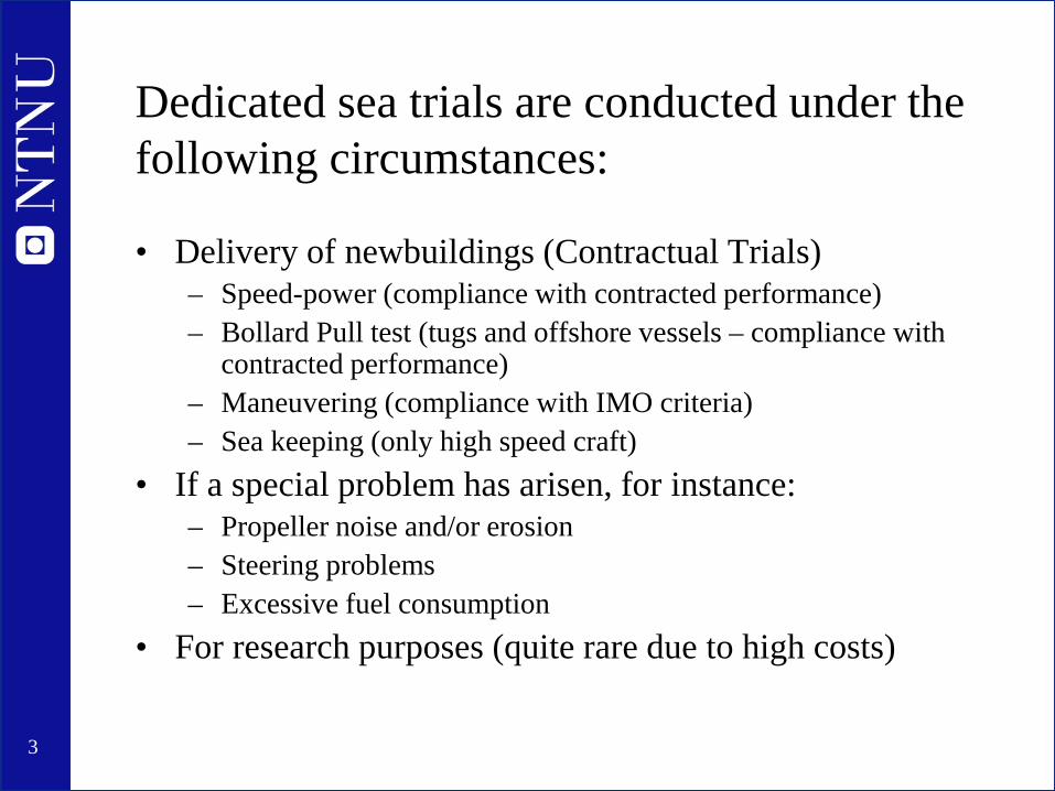
Dedicated sea trials are conducted under the following circumstances:
• Delivery of newbuildings (Contractual Trials) – Speed-power (compliance with contracted performance) – Bollard Pull test (tugs and offshore vessels – compliance with
contracted performance) – Maneuvering (compliance with IMO criteria) – Sea keeping (only high speed craft)
• If a special problem has arisen, for instance: – Propeller noise and/or erosion – Steering problems – Excessive fuel consumption
• For research purposes (quite rare due to high costs)

4
Delivery Sea trials (Contractual trials)
• Ship building contracts contain specific requirements for speed-power performance – Failure to meet requirements means fees to be paid and ultimately
that the ship owner has the right to refuse to accept the ship
• For tugs and offshore vessels, there will be requirements for bollard pull as well
• There might be requirements also for maneuvering trials : – Emergency stop test – Turning circles – Zig-zag tests
• High speed craft – requirements also for seakeeping tests – IMO: 2000 HSC Code (IMO 185E)
5
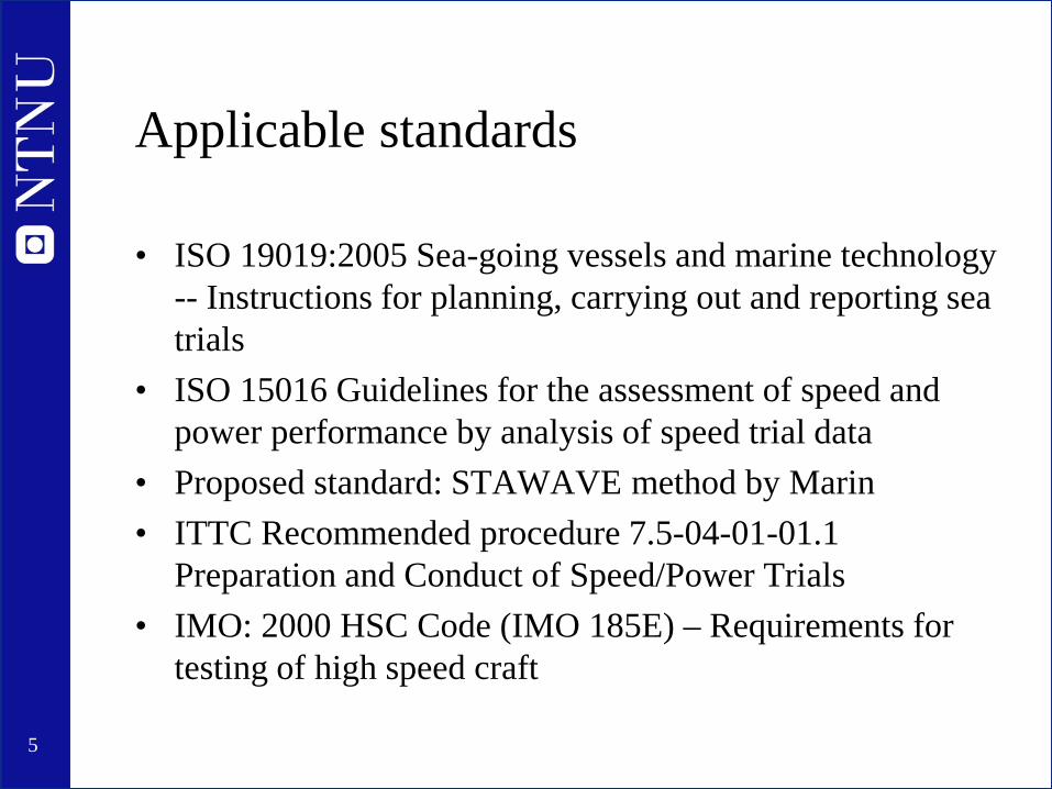
Applicable standards
• ISO 19019:2005 Sea-going vessels and marine technology -- Instructions for planning, carrying out and reporting sea trials
• ISO 15016 Guidelines for the assessment of speed and power performance by analysis of speed trial data
• Proposed standard: STAWAVE method by Marin • ITTC Recommended procedure 7.5-04-01-01.1
Preparation and Conduct of Speed/Power Trials • IMO: 2000 HSC Code (IMO 185E) – Requirements for
testing of high speed craft
6
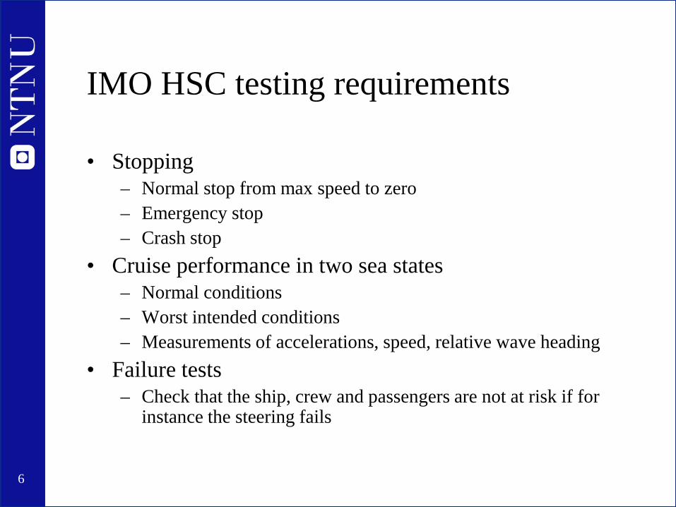
IMO HSC testing requirements
• Stopping – Normal stop from max speed to zero – Emergency stop – Crash stop
• Cruise performance in two sea states – Normal conditions – Worst intended conditions – Measurements of accelerations, speed, relative wave heading
• Failure tests – Check that the ship, crew and passengers are not at risk if for
instance the steering fails
7
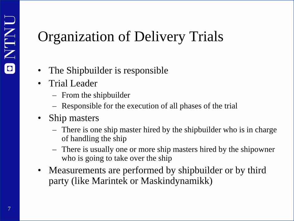
Organization of Delivery Trials
• The Shipbuilder is responsible • Trial Leader
– From the shipbuilder – Responsible for the execution of all phases of the trial
• Ship masters – There is one ship master hired by the shipbuilder who is in charge
of handling the ship – There is usually one or more ship masters hired by the shipowner
who is going to take over the ship • Measurements are performed by shipbuilder or by third
party (like Marintek or Maskindynamikk)
8
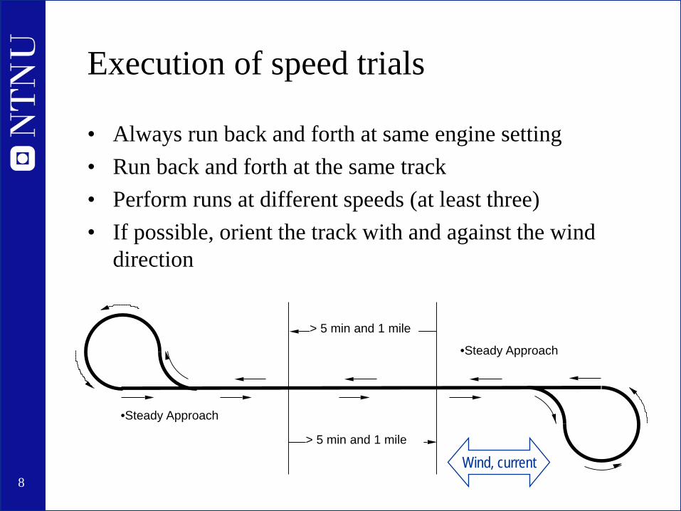
Execution of speed trials
• Always run back and forth at same engine setting • Run back and forth at the same track • Perform runs at different speeds (at least three) • If possible, orient the track with and against the wind
direction
•Steady Approach
> 5 min and 1 mile
•Steady Approach
> 5 min and 1 mile
Wind, current
9
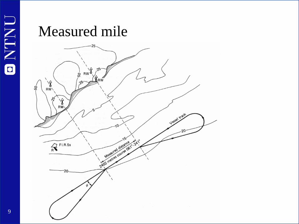
Measured mile
10
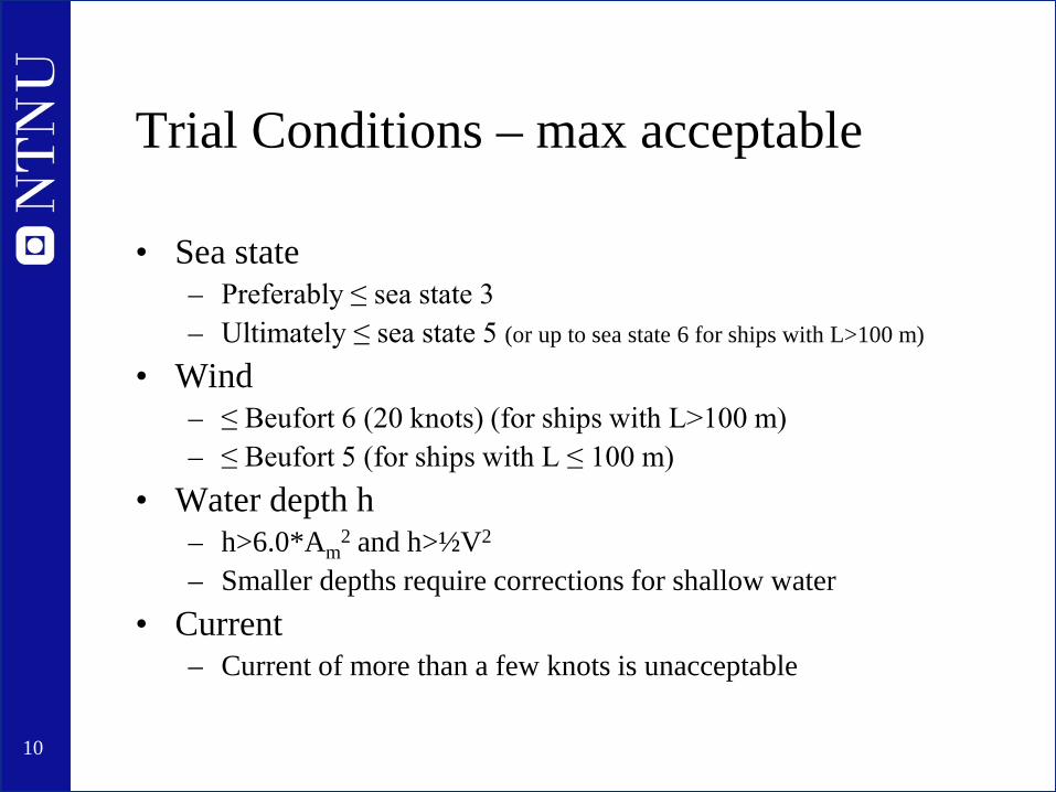
Trial Conditions – max acceptable
• Sea state – Preferably ≤ sea state 3 – Ultimately ≤ sea state 5 (or up to sea state 6 for ships with L>100 m)
• Wind – ≤ Beufort 6 (20 knots) (for ships with L>100 m) – ≤ Beufort 5 (for ships with L ≤ 100 m)
• Water depth h – h>6.0*Am
2 and h>½V2
– Smaller depths require corrections for shallow water • Current
– Current of more than a few knots is unacceptable
11
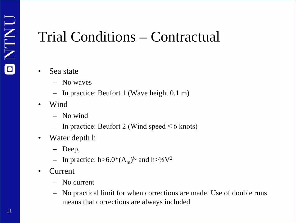
Trial Conditions – Contractual
• Sea state – No waves – In practice: Beufort 1 (Wave height 0.1 m)
• Wind – No wind – In practice: Beufort 2 (Wind speed ≤ 6 knots)
• Water depth h – Deep, – In practice: h>6.0*(Am)½ and h>½V2
• Current – No current – No practical limit for when corrections are made. Use of double runs
means that corrections are always included

12
Correction of trial results
• When trial conditions are not fulfilled corrections must be made
• Typical corrections: – Draught – interpolation in model test results on two draughts – Wind – calculation of wind resistance using empirical drag coef. or
results from wind tunnel tests – Shallow water – empirical formulas – Waves – calculation of added wave resistance and speed loss
• Standards for how corrections shall be performed: – ISO 15016 Guidelines for the assessment of speed and power … – ITTC Procedure for the Analysis of Speed/Power Trial Data – STAWAVE by Marin
• Comes with a free software package for performing the analysis

13
IMO Energy Efficiency Design Index - EEDI
• Increases the need for standardized trial and correction procedures
• The speed at 75% MCR in calm water must be accurately determined
• Now longer just a matter for yard and ship owner – Shall be approved by classification society
14
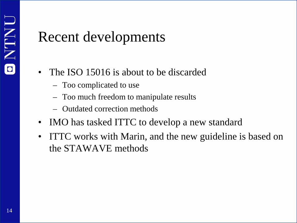
Recent developments
• The ISO 15016 is about to be discarded – Too complicated to use – Too much freedom to manipulate results – Outdated correction methods
• IMO has tasked ITTC to develop a new standard • ITTC works with Marin, and the new guideline is based on
the STAWAVE methods

15
Speed measurement
• “Speed over ground” and “Speed through water” • Timing a measured mile
– the old-fashioned way, only applicable to dedicated speed trials – Gives speed over ground
• GPS – The obvious choice, always used – Gives speed over ground
• Speed log – Device to measure speed through water – Always installed on ships – The accuracy is questionable!
16
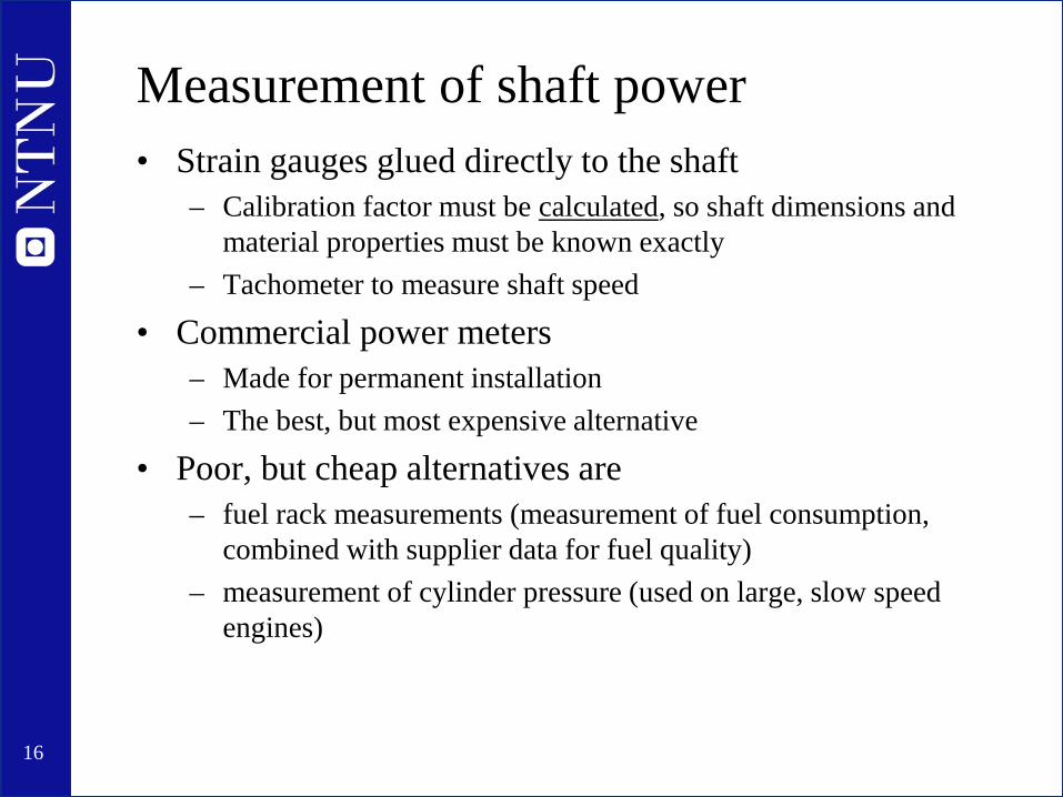
Measurement of shaft power • Strain gauges glued directly to the shaft
– Calibration factor must be calculated, so shaft dimensions and material properties must be known exactly
– Tachometer to measure shaft speed
• Commercial power meters – Made for permanent installation – The best, but most expensive alternative
• Poor, but cheap alternatives are – fuel rack measurements (measurement of fuel consumption,
combined with supplier data for fuel quality) – measurement of cylinder pressure (used on large, slow speed
engines)
17
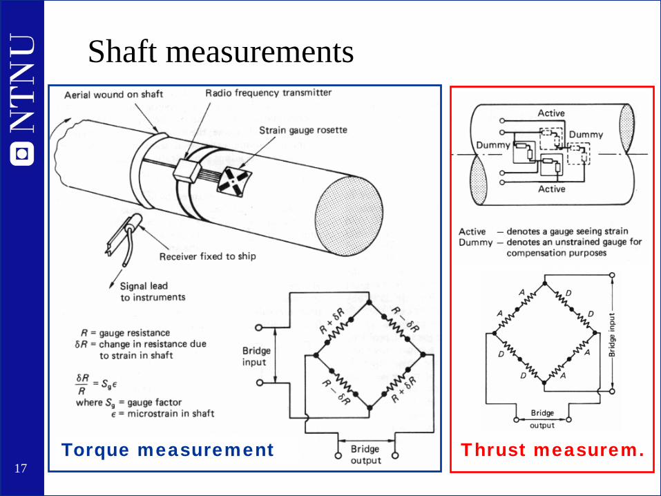
Shaft measurements
Torque measurement Thrust measurem.
18
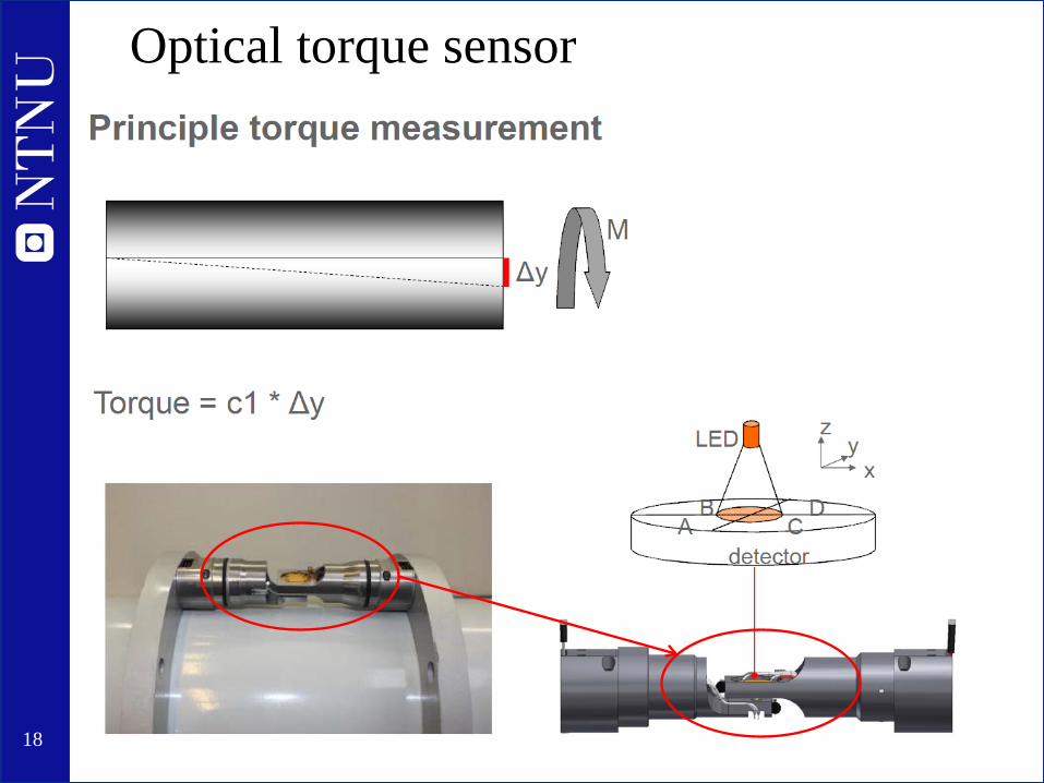
Optical torque sensor

19
Optical thrust and torque measurement
Required accuracy for thrust measurement is 25 naonometers! Challenging, but possible, according to supplier VAF Instruments
20
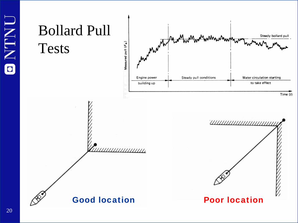
Bollard Pull Tests
Good location Poor location
21
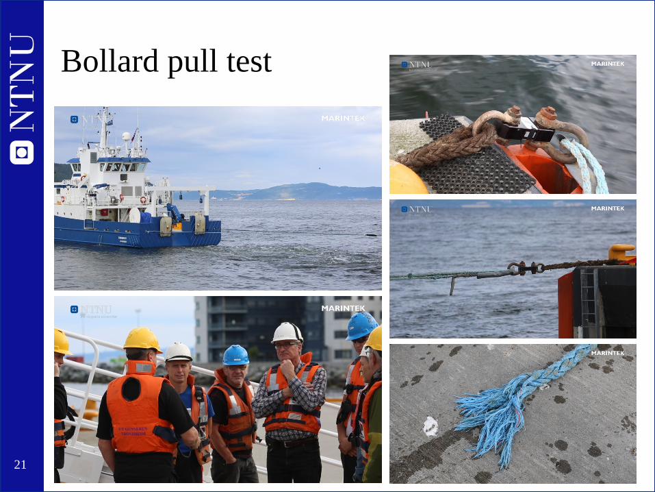
Bollard pull test
22
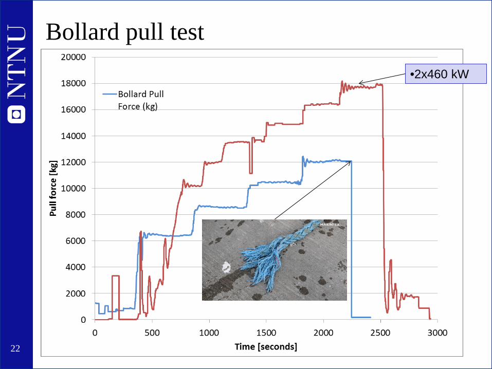
Bollard pull test •2x460 kW
23
Maneuvering trials
• Trial types and execution same as in model scale • Measurements:
– (D)GPS position measurement – Gyro compass course – Rate of turn (if possible) – Rudder angle – Propeller revs
24
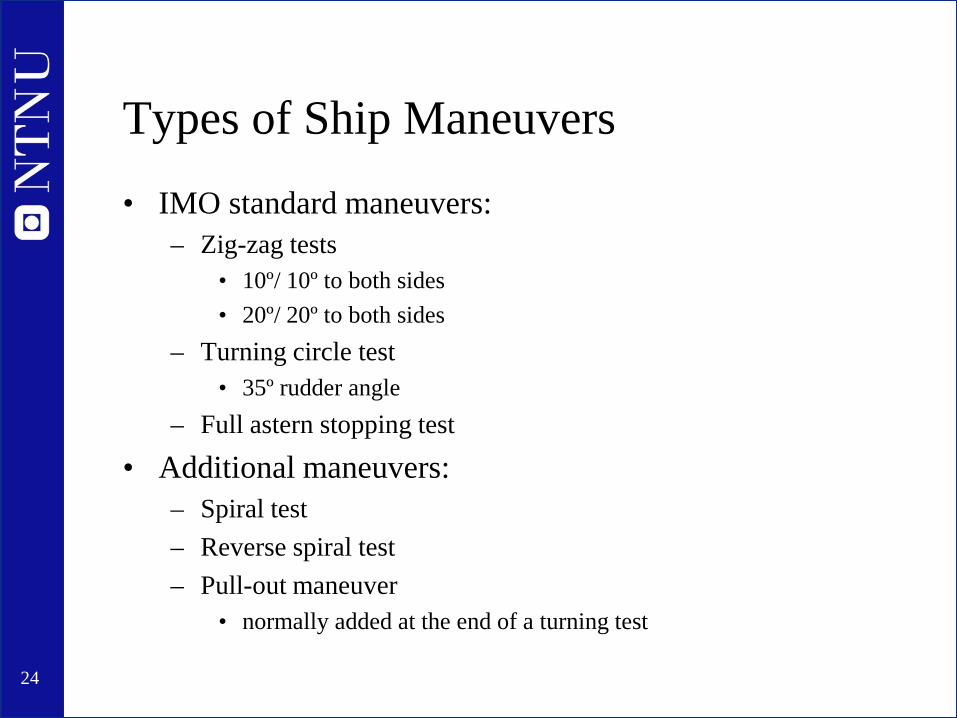
Types of Ship Maneuvers
• IMO standard maneuvers: – Zig-zag tests
• 10º/ 10º to both sides • 20º/ 20º to both sides
– Turning circle test • 35º rudder angle
– Full astern stopping test
• Additional maneuvers: – Spiral test – Reverse spiral test – Pull-out maneuver
• normally added at the end of a turning test
25
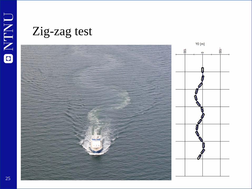
Zig-zag test

26
Test 2011: 20-20 zig zag

27
Turning circle
28
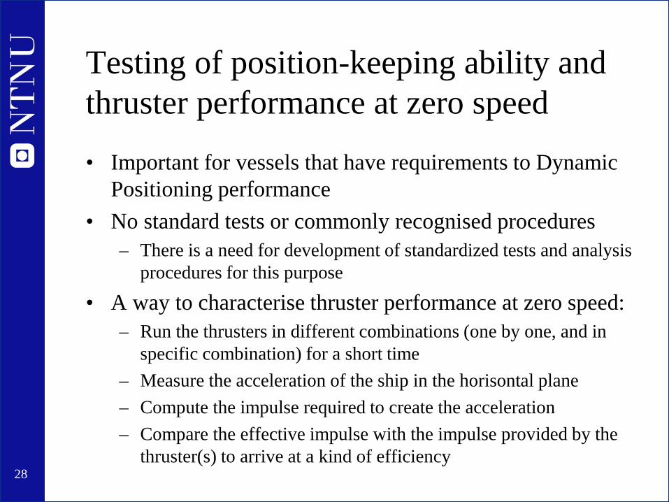
Testing of position-keeping ability and thruster performance at zero speed
• Important for vessels that have requirements to Dynamic Positioning performance
• No standard tests or commonly recognised procedures – There is a need for development of standardized tests and analysis
procedures for this purpose
• A way to characterise thruster performance at zero speed: – Run the thrusters in different combinations (one by one, and in
specific combination) for a short time – Measure the acceleration of the ship in the horisontal plane – Compute the impulse required to create the acceleration – Compare the effective impulse with the impulse provided by the
thruster(s) to arrive at a kind of efficiency

29
Measurements – environmental conditions • Water depth
– Echo sounder (ship instrument) or nautical charts • Water quality
– Temperature: Cooling water intake temperature can be used – Density: From nautical charts or density measurements
• Wind – Velocity and direction from anemometer – A separate, calibrated instrument is preferable – Watch out for influence of superstructure on the measurement
• Current – Nautical charts and tables – the difference in speed between double runs – a 360º turning test at low speed – The difference between log speed and GPS speed
• often, one doesn’t trust the speed log sufficiently for this purpose
30
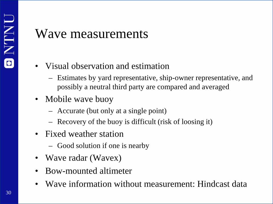
Wave measurements
• Visual observation and estimation – Estimates by yard representative, ship-owner representative, and
possibly a neutral third party are compared and averaged
• Mobile wave buoy – Accurate (but only at a single point) – Recovery of the buoy is difficult (risk of loosing it)
• Fixed weather station – Good solution if one is nearby
• Wave radar (Wavex) • Bow-mounted altimeter • Wave information without measurement: Hindcast data

31
Wave buoys • Fugro Oceanor Wavescan
– Directional wave spectrum – Wind – Current – Water temperature and salinity – Must be moored; large, heavy, costly
• Smaller, spherical buoys – Drifting or moored – Measures acceleration to determine wave
elevation, including period, but not direction – Usually measures position – for a drifting
buoy this can be used as an estimate of current
– Can be brought along for a full scale test
32
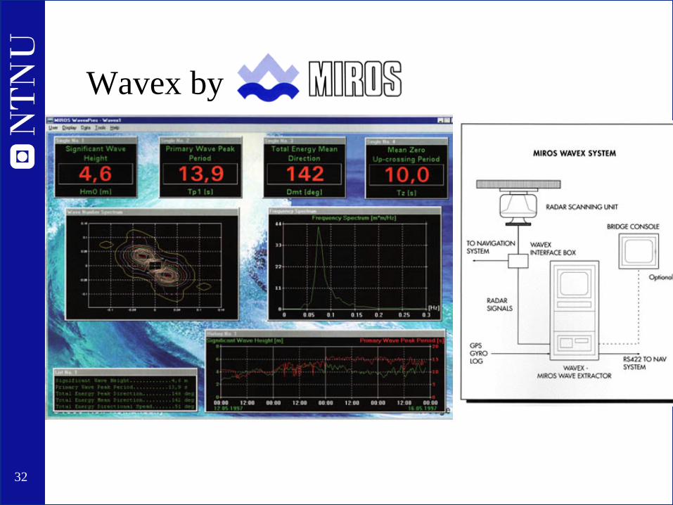
Wavex by Miros AS
33
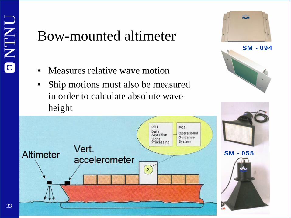
Bow-mounted altimeter
• Measures relative wave motion • Ship motions must also be measured
in order to calculate absolute wave height
SM - 055
SM - 094
35
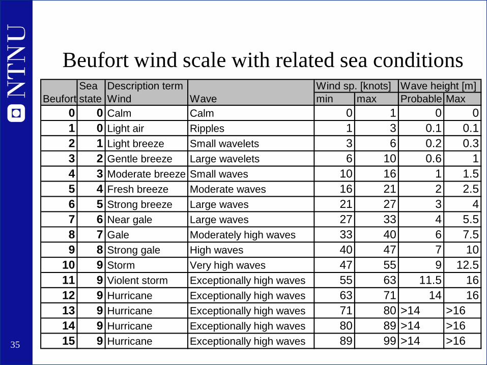
Beufort wind scale with related sea conditions Sea Description term Wind sp. [knots] Wave height [m]
Beufort state Wind Wave min max Probable Max0 0 Calm Calm 0 1 0 0 1 0 Light air Ripples 1 3 0.1 0.1 2 1 Light breeze Small wavelets 3 6 0.2 0.3 3 2 Gentle breeze Large wavelets 6 10 0.6 1 4 3 Moderate breeze Small waves 10 16 1 1.5 5 4 Fresh breeze Moderate waves 16 21 2 2.5 6 5 Strong breeze Large waves 21 27 3 4 7 6 Near gale Large waves 27 33 4 5.5 8 7 Gale Moderately high waves 33 40 6 7.5 9 8 Strong gale High waves 40 47 7 10
10 9 Storm Very high waves 47 55 9 12.5 11 9 Violent storm Exceptionally high waves 55 63 11.5 16 12 9 Hurricane Exceptionally high waves 63 71 14 16 13 9 Hurricane Exceptionally high waves 71 80 >14 >1614 9 Hurricane Exceptionally high waves 80 89 >14 >1615 9 Hurricane Exceptionally high waves 89 99 >14 >16

36

37
•Illustrations of Beufort wind (and wave) scale •From: http://en.wikipedia.org/wiki/Beaufort_scale
38
Hindcast data • Information about wave and wind condition in the past • Data collected by meteorological institutes
– From wave buoys, weather stations, satellites, observations …
• Many different sources – Might be hard to find the right source for your test – National Oceanic and Athospheric Administration www.noaa.gov
is the main source • Many different applications are using their open data
• From hindcast data you can get information about sea state and wind in your area – You can of course not get wave elevation time series!
• Generally only available for open ocean areas

40
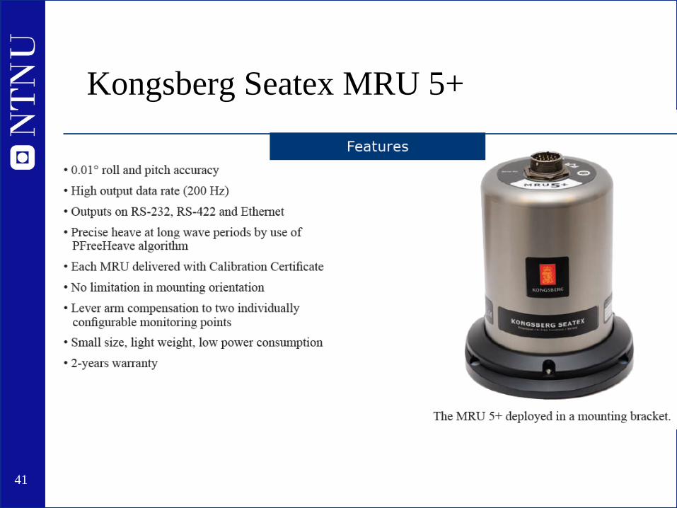
Measurement of motions • Accelerations: Conventional accelerometers • Angles: Gyros, compass, accelerometers • Rate gyro to measure rate of change of angles • Inertial Measurement Units (IMU)
– Consists of a number of accelerometers built into one compact unit – Gives out accelerations, velocities and motions at any point – Konsberg Seatex MRU is a good example of a commercial IMU
• Kongsberg Seapath – Combination of DGPS and IMU – for accurate position
measurement
41
Kongsberg Seatex MRU 5+

42
Kongsberg Seapath 330
43
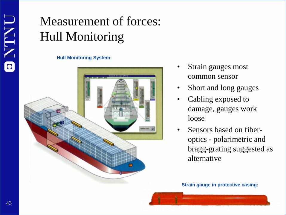
Measurement of forces: Hull Monitoring
• Strain gauges most common sensor
• Short and long gauges • Cabling exposed to
damage, gauges work loose
• Sensors based on fiber-optics - polarimetric and bragg-grating suggested as alternative
Hull Monitoring System:
Strain gauge in protective casing:

44
Rolls-Royce Health and Monitoring System - HEMOS
45
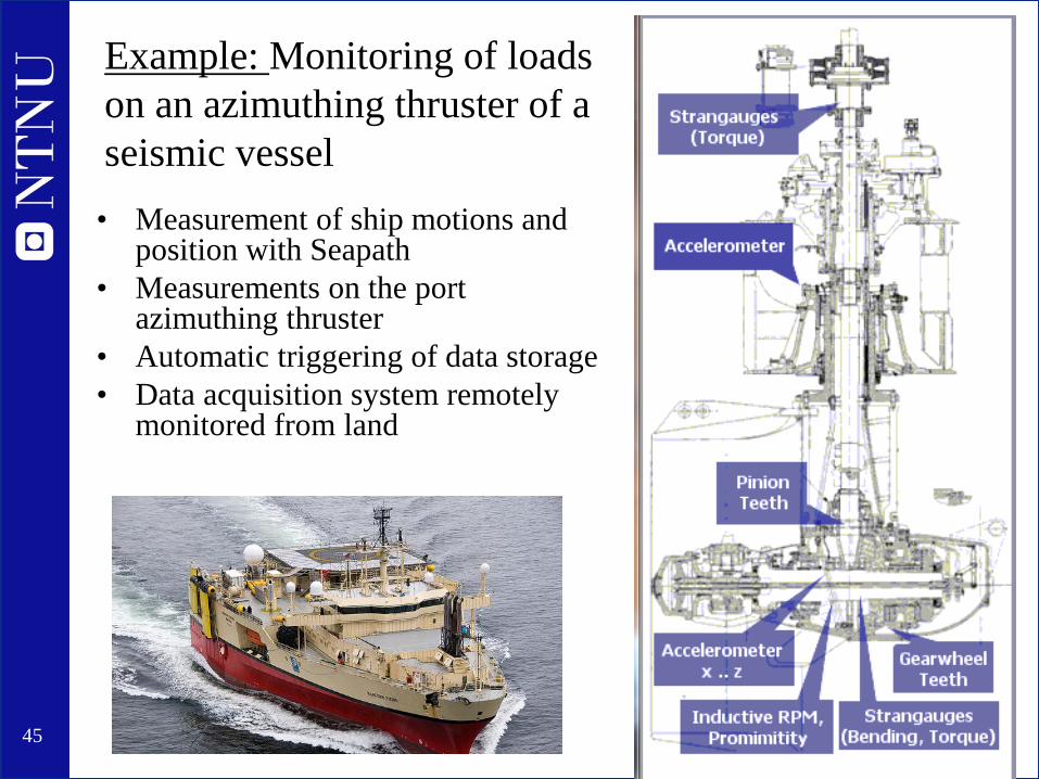
Example: Monitoring of loads on an azimuthing thruster of a seismic vessel
• Measurement of ship motions and position with Seapath
• Measurements on the port azimuthing thruster
• Automatic triggering of data storage • Data acquisition system remotely
monitored from land

46
Performance monitoring
• Typical merchant ship application: To monitor the development of speed and fuel consumption over time, in order to detect need for maintenance
• Challenges: – Monitoring and correcting for environmental conditions
• Waves, wind, water temperature – Accurate measurement of shaft power and speed through water – Correcting for loading condition – Data processing – Setting-up and running automatic data transmission

47
Propeller Cavitation Observations
Seen from below Seen from the side
48
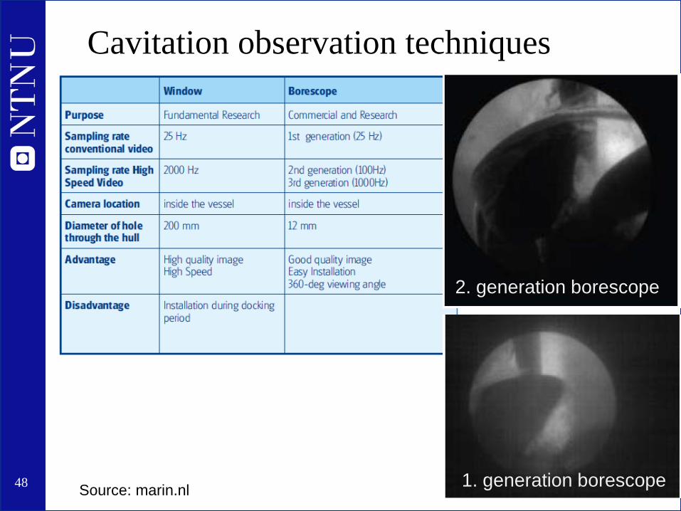
Cavitation observation techniques
1. generation borescope
2. generation borescope
Source: marin.nl
49
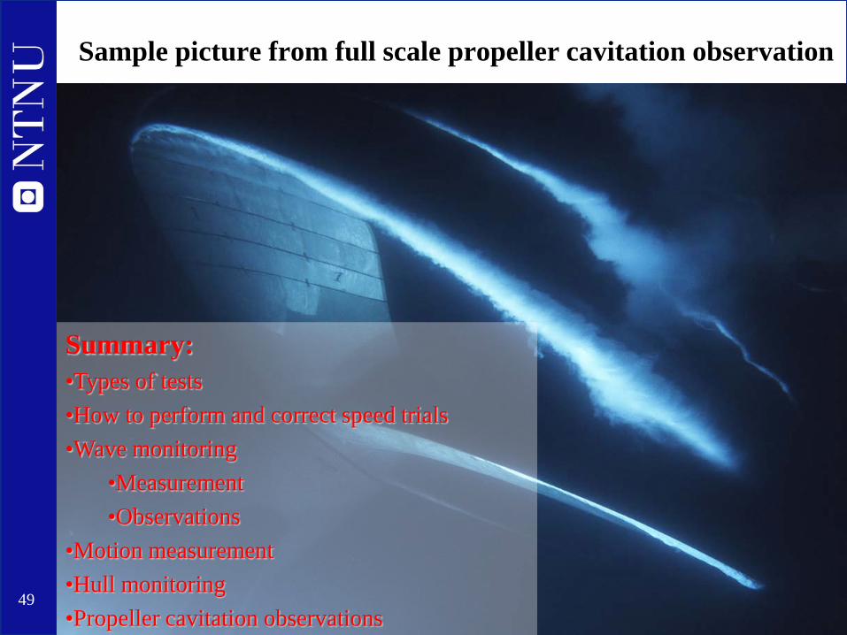
Sample picture from full scale propeller cavitation observation
Summary: •Types of tests •How to perform and correct speed trials •Wave monitoring
•Measurement •Observations
•Motion measurement •Hull monitoring •Propeller cavitation observations
Related Documents