SDI-12 User Guide AquaVent™ June 23, 2016

Welcome message from author
This document is posted to help you gain knowledge. Please leave a comment to let me know what you think about it! Share it to your friends and learn new things together.
Transcript
SDI-12 User GuideAquaVent™
June 23, 2016

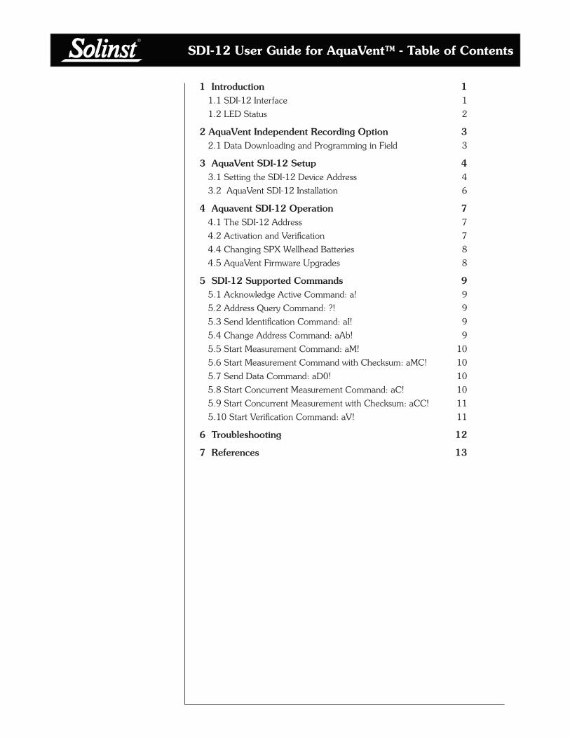
SDI-12 User Guide for AquaVent™ - Table of Contents
1 Introduction 11.1 SDI-12 Interface 1
1.2 LED Status 2
2 AquaVent Independent Recording Option 32.1 Data Downloading and Programming in Field 3
3 AquaVent SDI-12 Setup 43.1 Setting the SDI-12 Device Address 4
3.2 AquaVent SDI-12 Installation 6
4 Aquavent SDI-12 Operation 74.1 The SDI-12 Address 7
4.2 Activation and Verification 7
4.4 Changing SPX Wellhead Batteries 8
4.5 AquaVent Firmware Upgrades 8
5 SDI-12 Supported Commands 95.1 Acknowledge Active Command: a! 9
5.2 Address Query Command: ?! 9
5.3 Send Identification Command: aI! 9
5.4 Change Address Command: aAb! 9
5.5 Start Measurement Command: aM! 10
5.6 Start Measurement Command with Checksum: aMC! 10
5.7 Send Data Command: aD0! 10
5.8 Start Concurrent Measurement Command: aC! 10
5.9 Start Concurrent Measurement with Checksum: aCC! 11
5.10 Start Verification Command: aV! 11
6 Troubleshooting 12
7 References 13


SDI-12 User Guide for AquaVent™
Page 1
1 Introduction
SDI-12 (Serial Data Interface at 1200 Baud) is a communications protocol designed to allow the interfacing of a number of low power analog sensors with a common SDI-12 recorder or datalogger (master). The AquaVent is able to act as an SDI-12 Sensor in an SDI-12 network simply by using the 3500 AquaVent SPX Wellhead and SDI-12 Connector Cable.
The SPX Wellhead (translator) converts SDI-12 commands to the Solinst communications protocol for the AquaVent. The SPX Wellhead and SDI-12 Connector Cable provide a hardware and protocol conversion interface between a Solinst AquaVent and an SDI-12 network.
1.1 SDI-12 Interface
Solinst 2-wire signals are converted to SDI-12 signals by the SPX Wellhead. The SDI-12 Connector Cable, plugged into the side of this Wellhead, has three wires which connect to an SDI-12 master. These wires are colour-coded according to Table 1-1.
The bottom of the Wellhead connects to a AquaVent logger through a Vented Cable. The AquaVent logger contains a small battery, used only for memory and clock back-up. The Wellhead contains four user-replaceable 1.5 V AA lithium batteries that power the AquaVent logger.
The SDI-12 interface circuitry requires the +12V connection to be powered by customer equipment. The current draw from the 12 volt source normally peaks at several 10’s of mA, but idles around 30 uA. Upon initial power-up, or after disconnecting from Levelogger PC Software, the Wellhead draws about 3 mA from the SDI-12 equipment, while waiting to connect to the SDI-12 network. After the first SDI-12 command is received, the Wellhead idles around 30 uA.
NOTE
For more information about the AquaVent logger, Wellheads and Vented Cables, see the general AquaVent User Guide.
Wire Colour SDI-12 Function Connection
Red 12 Volt Line +12V DC at SDI-12 Master
Black Ground Line Ground at SDI-12 Master
White Serial Data Line SDI-12 Data at SDI-12 Master
Table 1-1 SDI-12 Interface Cable Wire Definitions
The communication settings for the SPX Wellhead hardware comply with the SDI-12 standard at 1200 baud, 1 start bit, 7 data bits, 1 parity bit (even parity), and 1 stop bit.
Technical Specifications
Standard Compliance: SDI-12 Protocol, Version 1.3, July 18, 2005, except 'A' command
Maximum Sample Rate: 1 SDI-12 sample every 3 seconds with AquaVent not logging.
+12V Input: 9.6VDC-16.0VDC
Supply Current: Normally peaks at several 10’s of mA, but idles around 30 uA.
SDI-12 Connector Cable Length: 15 ft (4.5 m)
Maximum Vented Cable Length: 500 ft (150 m)
Wellhead Operating Temperature: -20ºC - 80ºC
Wellhead IP Rating: IP 64 (dust and splash resistant)
Table 1-2 SDI-12 Technical Specifications

SDI-12 User Guide for AquaVent™
Page 2
1.2 LED Status
The 3500 AquaVent SPX Wellhead contains a multicolour LED.
The Yellow LED flashes whenever the AquaVent replies to a data recorder command on the SDI-12 network. The Yellow LED does not flash when it receives a command, only when it replies to a command.
The following will also occur:
Tricolour spin (3 cycles) to indicate a power-on event.
Alternating Yellow/Green for 10 rapid cycles to indicate that AquaVent communication has been established, the SDI-12 device address has been set to represent that AquaVent and SDI-12 interface is online.
Alternating Yellow/Red for 10 rapid cycles would instead mean that communication was NOT established, so the SDI-12 interface has been brought online using the default device address of ASCII ‘0’. (Check the batteries and the AquaVent logger connections).

SDI-12 User Guide for AquaVent™
Page 3
2 AquaVent Independent Recording Option
The AquaVent logger has the ability to record and store readings in its internal memory, independent from the SDI-12 network, while connected to an SDI-12 master. Before connecting the AquaVent to the SDI-12 master, it can be programmed and started using Solinst Levelogger PC Software (see Figure 3-1).
All standard sampling options provided by Solinst Levelogger PC Software are available while the AquaVent is operating as an SDI-12 sensor. The AquaVent logger can be set to record at a user-defined sampling rate; event, linear, and scheduled sampling modes are available. This allows the AquaVent logger to provide back-up data if the SDI-12 network fails. The AquaVent logger stores the data in its internal memory, until it is downloaded.
If you program the AquaVent logger at a similar interval to the SDI-12 recorder, it may require an occasional measurement retry by the recorder if the AquaVent happens to be busy at that moment. You can change the schedule of either to ensure this does not happen.
Each time the SDI-12 master asks the AquaVent for a current reading, the Wellhead batteries are used to transmit the information from the logger to the Wellhead. The AquaVent logger will also be using the batteries if programmed to record independently - draining the batteries more quickly.
2.1 Data Downloading and Programming in Field
If the AquaVent logger has been programmed to record on its own independent schedule, data can be downloaded from the AquaVent using a laptop and USB Connector Cable in the field (see Figure 3-1). Temporarily disconnect the AquaVent from the SDI-12 Connector Cable, preferably in between recordings by the SDI-12 master. Connect a laptop and download the independently recorded data.
If the AquaVent is disconnected from the SDI-12 network, and the SDI-12 master tries to communicate with the AquaVent, the SDI-12 master and the rest of the sensors in the network are not disrupted.
After the data download is complete, the AquaVent is easily connected back into the SDI-12 network without disruption. The AquaVent is automatically verified when reconnected (see Section 4.2).
NOTE
See the general AquaVent User Guide for detailed AquaVent operating instructions.
NOTE
Once you are finished programming your AquaVent, unplug the USB Connector Cable from the Wellhead. The Wellhead only communicates with the SDI-12 network when just the SDI-12 Connector Cable is connected.
NOTE
The Wellhead batteries will drain more quickly if the AquaVent logger is also set to record independently.
NOTE
Other downloading options are available using the Solinst Levelogger App and DataGrabber. See separate operating instructions.

SDI-12 User Guide for AquaVent™
Page 4
SPX Wellhead
USB Connector Cable
Vented Cable
AquaVent Logger
3 AquaVent SDI-12 Setup
3.1 Setting the SDI-12 Device Address
As the SPX Wellhead acquires its identity from the AquaVent logger, in the absence of a functional AquaVent logger, or without setting a specific address, the Wellhead will power up with a default address of "0".
To set the device address for the AquaVent logger, it must be connected to the Levelogger PC Software. The AquaVent communicates with the Software using a USB Connector Cable connected to the SPX Wellhead. The USB Connector Cable connects to the 10-pin (Solinst Protocol) connector on the Wellhead.
NOTE
For information on downloading and starting the Levelogger PC Software, see the general AquaVent User Guide.
NOTE
The SDI-12 Connector Cable can remain in place while programming the AquaVent logger.
Figure 3-1 Communicating with Levelogger Software
SDI-12 User Guide for AquaVent™
Page 5
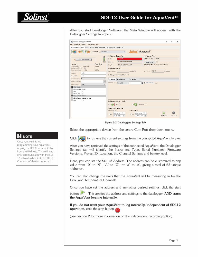
After you start Levelogger Software, the Main Window will appear, with the Datalogger Settings tab open.
Figure 3-2 Dataloggers Settings Tab
Select the appropriate device from the centre Com Port drop-down menu.
Click
to retrieve the current settings from the connected AquaVent logger.
After you have retrieved the settings of the connected AquaVent, the Datalogger Settings tab will identify the Instrument Type, Serial Numbers, Firmware Versions, Project ID, Location, the Channel Settings and battery level.
Here, you can set the SDI-12 Address. The address can be customized to any value from “0” to “9”, “A” to “Z”, or “a” to “z”, giving a total of 62 unique addresses.
You can also change the units that the AquaVent will be measuring in for the Level and Temperature Channels.
Once you have set the address and any other desired settings, click the start
button . This applies the address and settings to the datalogger, AND starts the AquaVent logging internally.
If you do not want your AquaVent to log internally, independent of SDI-12 operation, click the stop button .
(See Section 2 for more information on the independent recording option).
NOTE
Once you are finished programming your AquaVent, unplug the USB Connector Cable from the Wellhead. The Wellhead only communicates with the SDI-12 network when just the SDI-12 Connector Cable is connected.

SDI-12 User Guide for AquaVent™
Page 6
Figure 3-3 AquaVent SDI-12 Installation
Wire Connections to SDI-12
Master
SDI-12 Connector Cable
3.2 AquaVent SDI-12 Installation
1) Be sure that an AquaVent logger is properly connected to the SPX Wellhead using a Vented Cable.
2) Turn off the power to the SDI-12 master and/or the SDI-12 network.
3) From the SDI-12 Connector Cable, take the black ground wire and connect it to the master ground terminal; take the white signal wire and connect it to the SDI-12 data signal wire of the master; take the red wire and connect it to the 12 VDC power supply of the master or SDI-12 network.
4) Be sure the SDI-12 Connector Cable is connected to the SPX Wellhead. (Ensure you have unplugged the USB Connector Cable after programming the AquaVent with Levelogger Software).
5) Turn on power to the SDI-12 master and/or the SDI-12 network such that power is applied to the SDI-12 Connector Cable. The SPX Wellhead LED should emit the following signals in order:
• Tricolour spin (3 cycles) to indicate a power-on event.
• Alternating Yellow/Green for 10 rapid cycles indicate that AquaVent communication has been established, the SDI-12 device address has been set to represent that AquaVent, and the SDI-12 interface is online.
• Alternating Yellow/Red for 10 rapid cycles means that communication was NOT established, so the SDI-12 interface has been brought online using the default device address of ASCII ‘0’. (Check the AquaVent logger connections).
6) The SPX Wellhead and the AquaVent logger are physically and properly hooked up to the SDI-12 master and the SDI-12 network.
NOTE
See the general AquaVent User Guide for detailed AquaVent installation Instructions.
SPX Wellhead
Vented Cable
AquaVent Logger
SDI-12 User Guide for AquaVent™
Page 7
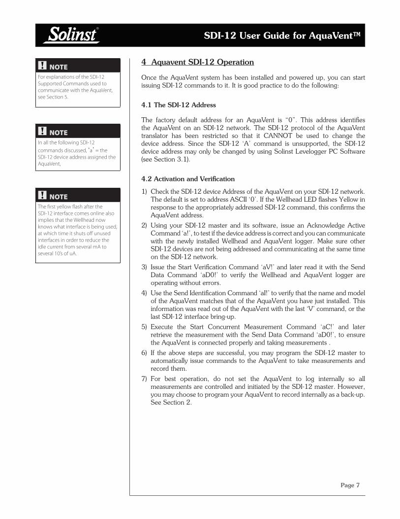
4 Aquavent SDI-12 Operation
Once the AquaVent system has been installed and powered up, you can start issuing SDI-12 commands to it. It is good practice to do the following:
4.1 The SDI-12 Address
The factory default address for an AquaVent is “0”. This address identifies the AquaVent on an SDI-12 network. The SDI-12 protocol of the AquaVent translator has been restricted so that it CANNOT be used to change the device address. Since the SDI-12 ‘A’ command is unsupported, the SDI-12 device address may only be changed by using Solinst Levelogger PC Software (see Section 3.1).
4.2 Activation and Verification
1) Check the SDI-12 device Address of the AquaVent on your SDI-12 network. The default is set to address ASCII ‘0’. If the Wellhead LED flashes Yellow in response to the appropriately addressed SDI-12 command, this confirms the AquaVent address.
2) Using your SDI-12 master and its software, issue an Acknowledge Active Command ‘a!’, to test if the device address is correct and you can communicate with the newly installed Wellhead and AquaVent logger. Make sure other SDI-12 devices are not being addressed and communicating at the same time on the SDI-12 network.
3) Issue the Start Verification Command ‘aV!’ and later read it with the Send Data Command ‘aD0!’ to verify the Wellhead and AquaVent logger are operating without errors.
4) Use the Send Identification Command ‘aI!’ to verify that the name and model of the AquaVent matches that of the AquaVent you have just installed. This information was read out of the AquaVent with the last ‘V’ command, or the last SDI-12 interface bring-up.
5) Execute the Start Concurrent Measurement Command ‘aC!’ and later retrieve the measurement with the Send Data Command ‘aD0!’, to ensure the AquaVent is connected properly and taking measurements .
6) If the above steps are successful, you may program the SDI-12 master to automatically issue commands to the AquaVent to take measurements and record them.
7) For best operation, do not set the AquaVent to log internally so all measurements are controlled and initiated by the SDI-12 master. However, you may choose to program your AquaVent to record internally as a back-up. See Section 2.
NOTE
For explanations of the SDI-12 Supported Commands used to communicate with the AquaVent, see Section 5.
NOTE
In all the following SDI-12 commands discussed, ‘a’ = the SDI-12 device address assigned the AquaVent,
NOTE
The first yellow flash after the SDI-12 interface comes online also implies that the Wellhead now knows what interface is being used, at which time it shuts off unused interfaces in order to reduce the idle current from several mA to several 10’s of uA.

SDI-12 User Guide for AquaVent™
Page 8
4.3 Changing or Updating AquaVent Loggers
If a new AquaVent logger is attached to the SPX Wellhead, or you have changed the AquaVent settings, ensure that the Wellhead power is disconnected temporarily (30 seconds) by unplugging the SDI-12 Connector Cable from the side of the Wellhead. This is so the SDI-12 translator will re-initialize, in order to cause the new SDI-12 device address or settings to be retrieved from the AquaVent logger.
4.4 Changing SPX Wellhead Batteries
After replacing the batteries, it is recommended that the Solinst Levelogger PC Software Diagnostic Utility is used to reset the battery indicator. See the General AquaVent User Guide for instructions to do this.
Power cycle the Wellhead by temporarily (30 seconds) unplugging the SDI-12 Connector Cable. This will cause the Wellhead to re-connect with the AquaVent.
Wait for the LED to indicate a good connection. Try re-connecting if the first try fails.
4.5 AquaVent Firmware Upgrades
See the general AquaVent User Guide for details on firmware upgrades to the AquaVent logger and the SPX Wellhead.
The SPX Wellhead needs the 12V power supply connected to the SDI-12 Connector Cable in order to perform the firmware upgrade.
While the firmware is being updated, the SPX Wellhead will ignore or provide time-out response to any requests from the SDI-12 network.
NOTE
For more information about the AquaVent logger, Wellheads and Vented Cables, see the general AquaVent User Guide.

SDI-12 User Guide for AquaVent™
Page 9
5 SDI-12 Supported Commands
Please refer to the document: SDI-12: A Serial Digital Interface Standard for Microprocessor-Based Sensors, Version 1.3, July 18, 2005, prepared by the SDI-12 Support Group (Technical Committee), for a complete description of the SDI-12 protocol. (http://www.sdi-12.org/).
The following commands are supported:
5.1 Acknowledge Active Command: a!
This command is used to ensure that an AquaVent is responding to the SDI-12 master. A typical command/reply would be: 0!0<CR><LF> where the ‘0’s represents the AquaVent SDI-12 device address and <CR> represents a carriage return (Hex 0D) and <LF> represents a line feed (Hex 0A). All replies from an AquaVent are terminated with <CR><LF>. All SDI-12 master commands are terminated with an exclamation mark ‘!’ character.
5.2 Address Query Command: ?!
Using a question mark (?) as the address character causes the AquaVent to respond with the acknowledge active ‘a!’ command where ‘a’ represents the AquaVent address. A typical command/reply would be: ?!0<CR><LF>. The bold-faced characters are sent to the AquaVent; the normal type-face is the AquaVent’s reply. In this case the AquaVent address is “0”. This command is good for determining the AquaVent address, if it is the only datalogger connected on the SDI-12 network.
5.3 Send Identification Command: aI!
This command is used to query AquaVent loggers for their SDI-12 compatibility level, model number, and firmware version number. A typical command/reply would be: 0I! 013SOLINST M20 10 1.000 1017687<CR><LF> where the first “0” is the AquaVent address, “13” represents SDI-12 V1.3 protocol support, “SOLINST ” identifies the AquaVent manufacturer, “M20” defines the AquaVent logger model number, “10” is the hardware identifier, “1.000” specifies the current firmware version, and “1017687” represents the AquaVent logger’s serial number.
5.4 Change Address Command: aAb!
This command is NOT supported by the Solinst AquaVent system (see Section 3.1).
NOTE
In all the following SDI-12 commands discussed, ‘a’ = the SDI-12 device address assigned the AquaVent,

SDI-12 User Guide for AquaVent™
Page 10
5.5 Start Measurement Command: aM!
This command tells the AquaVent to take a measurement. However, the measurement is not returned after this command. Instead, the time and number of measurements that can be expected will be replied. For example: 0M!00102<CR><LF> where the first “0” is the AquaVent address, the next three digits “010” represent the time in seconds it will take the AquaVent to take the readings, and the final “2” indicates how many readings will be returned. The Solinst AquaVent will return a temperature and level measurement which are always ready to be read after the specified time, after that the SDI-12 master can issue the Send Data command 0D0! to retrieve the measurement data. Other start measurement commands such as aM1 to aM9 are reserved for future use.
5.6 Start Measurement Command with Checksum: aMC!
This command is identical to the aM! command with the exception that a three-character checksum is returned before the <CR><LF> as part of the Send Data command reply. The aMC1 to aMC9 commands are reserved for future use.
5.7 Send Data Command: aD0!
This command is used to get groups of data from the AquaVent. An aD0! command is issued by the master after a M, MC, C, CC, or V command. The AquaVent responds by sending the data. For a Solinst AquaVent, this is currently two data items: temperature and level measurements. A typical command/reply is:
0D0!0+24.2981+0.35212<CR><LF> where the temperature is the “+24.2981” in degrees Celsius and the level is the “+0.35212” in meters. It is possible to change level units using Levelogger Software, but the actual units in use are not reported while the AquaVent is in SDI-12 mode.
In response to a checksum request i.e. MC, CC; a typical command/reply is: 0D0!0+24.2981+0.35212MQ_<CR><LF> where the temperature and level are as before and the final “MQ_” is the checksum. Refer to the SDI-12 specification for details on the checksum generation. For the M and C commands if a measurement cannot be obtained, the D command will return 0000<CR><LF> to indicate the measurement could not be obtained. The aD1 to aD9 commands are reserved for future use.
5.8 Start Concurrent Measurement Command: aC!
This command is similar to the Start Measurement Command except a concurrent measurement is taken. Like the Start Measurement Command, a Send Data Command is required to retrieve the data. For example: 0C!000302<CR><LF>. The reply indicates that two readings (temperature and pressure) are available after 3 seconds. A 0D0! command is then issued to read these AquaVent values. The aC1 to aC9 commands are reserved for future use.
NOTE
Checksum is a form of redundant test, which is used to check for any errors in the data.
NOTE
The actual units in use are not reported to the SDI-12 master while the AquaVent is in SDI-12 mode, but it is possible to change level units using the Solinst Levelogger PC Software (see Section 3.1)..

SDI-12 User Guide for AquaVent™
Page 11
5.9 Start Concurrent Measurement Command with Checksum: aCC!
This command is similar to the Start Concurrent Measurement with the addition of a checksum. For example: 0CC!000302<CR><LF> would then, after 3 seconds, reply to the aD0! command as follows:
0D0!0+24.6038+0.34513L<DEL>j<CR><LF>. Where “L<DEL>j” is the checksum for the two measurement values “+24.6038 + 0.34513. The aCC1 to aCC9 commands are reserved for future use.
5.10 Start Verification Command: aV!
This command tells the SPX Wellhead to return a verification (self-test) code in response to a subsequent aD0! command. In this case, the SPX Wellhead returns a non-zero time because the self-test execution verifies all internal memory checksums and these operations take about 13 seconds. A typical session would appear as follows:
0V!00131<CR><LF> indicates that one status reading will be ready in about 13 seconds.
0<CR><LF> is a service request from the SPX Wellhead within 13 seconds to indicate that the BIT operations are complete and the verification code is available.
0D0!0+000 is the Send Data command from the SDI-12 master device to obtain the BIT verification code of “+000” which indicates that no faults were found. The possible fault codes are shown in Table 5-1. All the decimal representations of the individual faults are summed to arrive at the resultant BIT verification code. An included bit in a certain bit position means the corresponding test has failed.
Code Bit Position Decimal Representation Test Meaning
0 1 Read Write AquaVent logger
1 2 SPX Wellhead FRAM Memory Test
2 4 SPX Wellhead FLASH Memory Checksum Test
3 8 N/A
4 16 N/A
5 32 N/A
6 64 N/A
7 128 N/A
Table 5-1 BIT Verification Fault Codes
SDI-12 User Guide for AquaVent™
Page 12
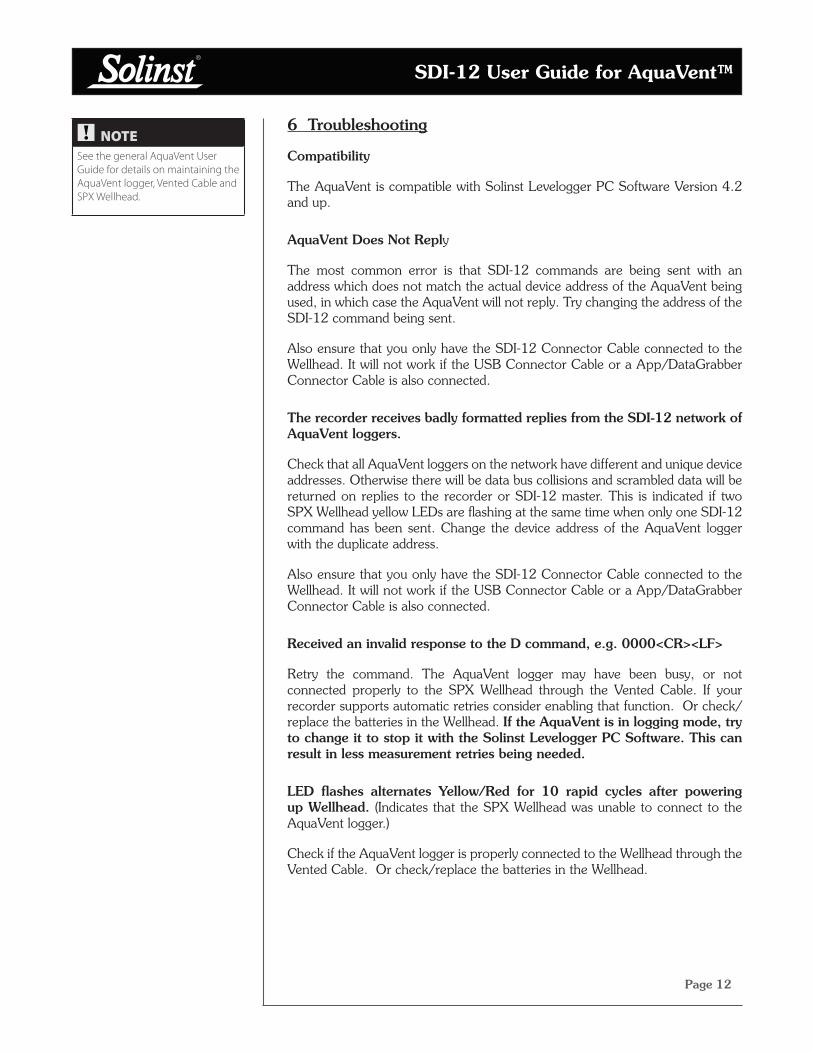
6 Troubleshooting
Compatibility
The AquaVent is compatible with Solinst Levelogger PC Software Version 4.2 and up.
AquaVent Does Not Reply
The most common error is that SDI-12 commands are being sent with an address which does not match the actual device address of the AquaVent being used, in which case the AquaVent will not reply. Try changing the address of the SDI-12 command being sent.
Also ensure that you only have the SDI-12 Connector Cable connected to the Wellhead. It will not work if the USB Connector Cable or a App/DataGrabber Connector Cable is also connected.
The recorder receives badly formatted replies from the SDI-12 network of AquaVent loggers.
Check that all AquaVent loggers on the network have different and unique device addresses. Otherwise there will be data bus collisions and scrambled data will be returned on replies to the recorder or SDI-12 master. This is indicated if two SPX Wellhead yellow LEDs are flashing at the same time when only one SDI-12 command has been sent. Change the device address of the AquaVent logger with the duplicate address.
Also ensure that you only have the SDI-12 Connector Cable connected to the Wellhead. It will not work if the USB Connector Cable or a App/DataGrabber Connector Cable is also connected.
Received an invalid response to the D command, e.g. 0000<CR><LF>
Retry the command. The AquaVent logger may have been busy, or not connected properly to the SPX Wellhead through the Vented Cable. If your recorder supports automatic retries consider enabling that function. Or check/replace the batteries in the Wellhead. If the AquaVent is in logging mode, try to change it to stop it with the Solinst Levelogger PC Software. This can result in less measurement retries being needed.
LED flashes alternates Yellow/Red for 10 rapid cycles after powering up Wellhead. (Indicates that the SPX Wellhead was unable to connect to the AquaVent logger.)
Check if the AquaVent logger is properly connected to the Wellhead through the Vented Cable. Or check/replace the batteries in the Wellhead.
NOTE
See the general AquaVent User Guide for details on maintaining the AquaVent logger, Vented Cable and SPX Wellhead.
SDI-12 User Guide for AquaVent™
Page 13
7 References
SDI-12 Support Group (Technical Committee). SDI-12: A Serial-Digital Interface Standard for Microprocessor-Based Sensors, Version 1.3, July 18, 2005. Available [online]: http://www.sdi-12.org/

Solinst Canada Ltd., 35 Todd Road, Georgetown, ON L7G 4R8 Fax: +1 (905) 873-1992; (800) 516-9081 Tel: +1 (905) 873-2255; (800) [email protected]
www.solinst.com
High Quality Groundwater and Surface Water Monitoring Instrumentation
Related Documents