SCROLL COMPRESSORS TYPE AIR COOLED PACKAGE CHILLERS SCOD_A SERIES Smartech International Sdn. Bhd. (822599-P) No.15, Jalan PJS 1/27, (Jalan Petaling Utama 6), Petaling Utama, Batu 7, Off Jalan Klang Lama, 46000 Petaling Jaya, Selangor. T: 603-7782 2788 / 7783 7288 F: 603-7782 3788 W: www.smart-hvac.com.my Specifications in this catalogue are subject to change without notice in order that SMARTECH may bring the latest innovations to their customer. SCODA-1216A SCROLL COMPRESSORS TYPE AIR COOLED PACKAGE CHILLERS Smartwise Innovations... Towards Green, Quality & Reliability Solutions

Welcome message from author
This document is posted to help you gain knowledge. Please leave a comment to let me know what you think about it! Share it to your friends and learn new things together.
Transcript

SCROLL COMPRESSORSTYPE AIR COOLEDPACKAGE CHILLERS
SCOD_A SERIES
Smartech International Sdn. Bhd.(822599-P)
No.15, Jalan PJS 1/27, (Jalan Petaling Utama 6), Petaling Utama, Batu 7,
Off Jalan Klang Lama, 46000 Petaling Jaya, Selangor.
T: 603-7782 2788 / 7783 7288 F: 603-7782 3788
W: www.smart-hvac.com.my
Specifications in this catalogue are subject to change without notice in order that SMARTECH may bring the latest innovations to their customer.
SCODA-1216A
SCROLL COMPRESSORSTYPE AIR COOLEDPACKAGE CHILLERS
Smartwise Innovations... Towards Green, Quality & Reliability Solutions
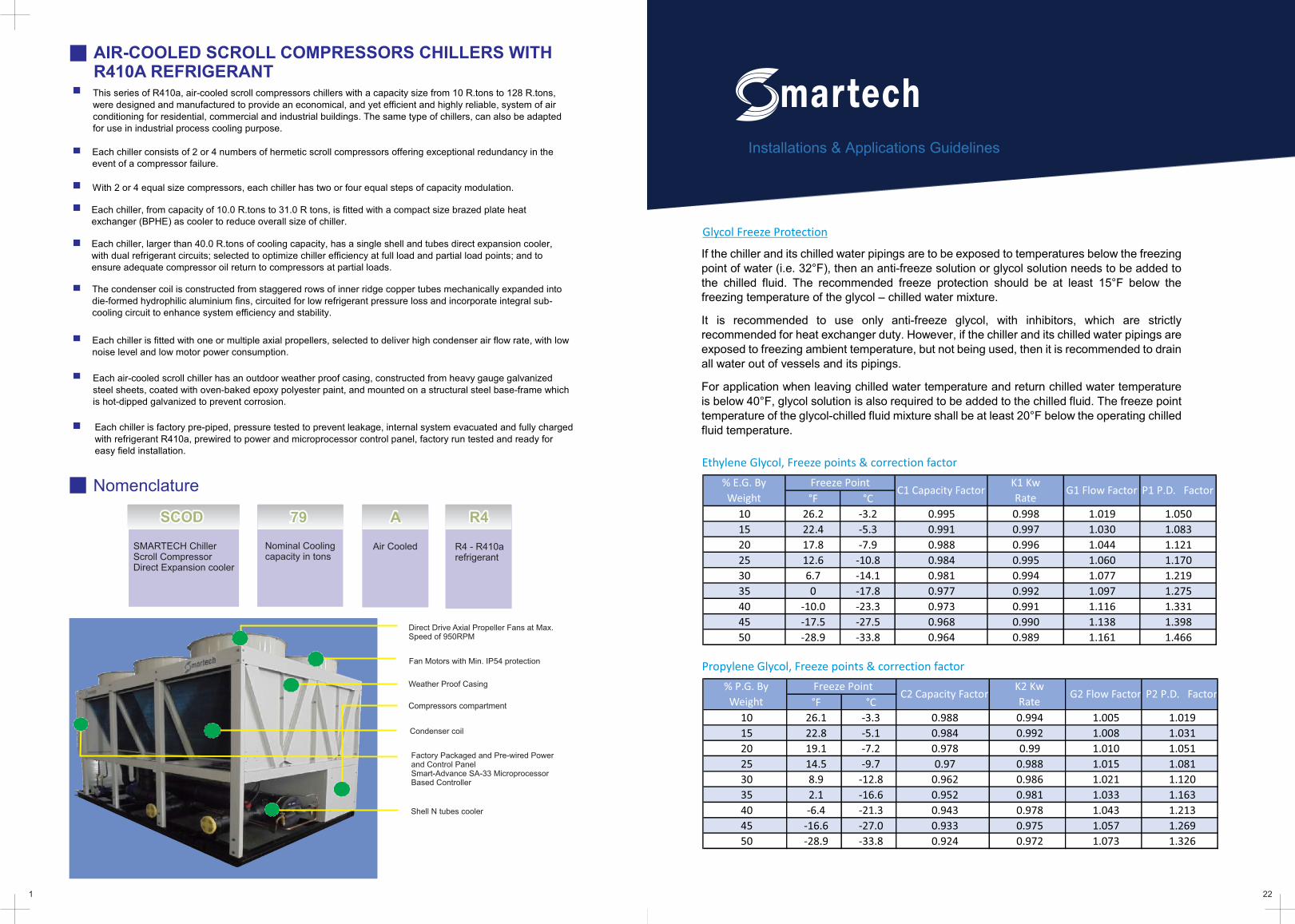
AIR-COOLED SCROLL COMPRESSORS CHILLERS WITH R410A REFRIGERANT
Direct Drive Axial Propeller Fans at Max. Speed of 950RPM
Fan Motors with Min. IP54 protection
Factory Packaged and Pre-wired Powerand Control Panel Smart-Advance SA-33 Microprocessor Based Controller
Weather Proof Casing
Nomenclature
SCODSCODSCOD AAA797979 R4R4R4
SMARTECH ChillerScroll CompressorDirect Expansion cooler
Nominal Coolingcapacity in tons
Air Cooled R4 - R410a refrigerant
1
This series of R410a, air-cooled scroll compressors chillers with a capacity size from 10 R.tons to 128 R.tons, were designed and manufactured to provide an economical, and yet efficient and highly reliable, system of air conditioning for residential, commercial and industrial buildings. The same type of chillers, can also be adapted for use in industrial process cooling purpose.
Each chiller consists of 2 or 4 numbers of hermetic scroll compressors offering exceptional redundancy in the event of a compressor failure.
With 2 or 4 equal size compressors, each chiller has two or four equal steps of capacity modulation.
Each chiller, larger than 40.0 R.tons of cooling capacity, has a single shell and tubes direct expansion cooler, with dual refrigerant circuits; selected to optimize chiller efficiency at full load and partial load points; and to ensure adequate compressor oil return to compressors at partial loads.
The condenser coil is constructed from staggered rows of inner ridge copper tubes mechanically expanded into die-formed hydrophilic aluminium fins, circuited for low refrigerant pressure loss and incorporate integral sub-cooling circuit to enhance system efficiency and stability.
Each chiller is fitted with one or multiple axial propellers, selected to deliver high condenser air flow rate, with low noise level and low motor power consumption.
Each air-cooled scroll chiller has an outdoor weather proof casing, constructed from heavy gauge galvanized steel sheets, coated with oven-baked epoxy polyester paint, and mounted on a structural steel base-frame which is hot-dipped galvanized to prevent corrosion.
Each chiller is factory pre-piped, pressure tested to prevent leakage, internal system evacuated and fully charged with refrigerant R410a, prewired to power and microprocessor control panel, factory run tested and ready for easy field installation.
Compressors compartment
Condenser coil
Shell N tubes cooler
Each chiller, from capacity of 10.0 R.tons to 31.0 R tons, is fitted with a compact size brazed plate heat exchanger (BPHE) as cooler to reduce overall size of chiller.
22
If the chiller and its chilled water pipings are to be exposed to temperatures below the freezing point of water (i.e. 32°F), then an anti-freeze solution or glycol solution needs to be added to the chilled fluid. The recommended freeze protection should be at least 15°F below the freezing temperature of the glycol – chilled water mixture.
It is recommended to use only anti-freeze glycol, with inhibitors, which are strictly recommended for heat exchanger duty. However, if the chiller and its chilled water pipings are exposed to freezing ambient temperature, but not being used, then it is recommended to drain all water out of vessels and its pipings.
For application when leaving chilled water temperature and return chilled water temperature is below 40°F, glycol solution is also required to be added to the chilled fluid. The freeze point temperature of the glycol-chilled fluid mixture shall be at least 20°F below the operating chilled fluid temperature.
Installations & Applications Guidelines
Glycol Freeze Protection
Ethylene Glycol, Freeze points & correction factor
Propylene Glycol, Freeze points & correction factor
°F °C
10 26.2 -3.2 0.995 0.998 1.019 1.050
15 22.4 -5.3 0.991 0.997 1.030 1.083
20 17.8 -7.9 0.988 0.996 1.044 1.121
25 12.6 -10.8 0.984 0.995 1.060 1.170
30 6.7 -14.1 0.981 0.994 1.077 1.219
35 0 -17.8 0.977 0.992 1.097 1.275
40 -10.0 -23.3 0.973 0.991 1.116 1.331
45 -17.5 -27.5 0.968 0.990 1.138 1.398
50 -28.9 -33.8 0.964 0.989 1.161 1.466
P1 P.D. Factor% E.G. By
Weight
Freeze PointC1 Capacity Factor
K1 Kw
RateG1 Flow Factor
°F °C
10 26.1 -3.3 0.988 0.994 1.005 1.019
15 22.8 -5.1 0.984 0.992 1.008 1.031
20 19.1 -7.2 0.978 0.99 1.010 1.051
25 14.5 -9.7 0.97 0.988 1.015 1.081
30 8.9 -12.8 0.962 0.986 1.021 1.120
35 2.1 -16.6 0.952 0.981 1.033 1.163
40 -6.4 -21.3 0.943 0.978 1.043 1.213
45 -16.6 -27.0 0.933 0.975 1.057 1.269
50 -28.9 -33.8 0.924 0.972 1.073 1.326
P2 P.D. Factor% P.G. By
Weight
Freeze PointC2 Capacity Factor
K2 Kw
RateG2 Flow Factor
MECHANICAL SPECIFICATIONS AND FEATURES
HERMETIC SCROLL COMPRESSORS
221
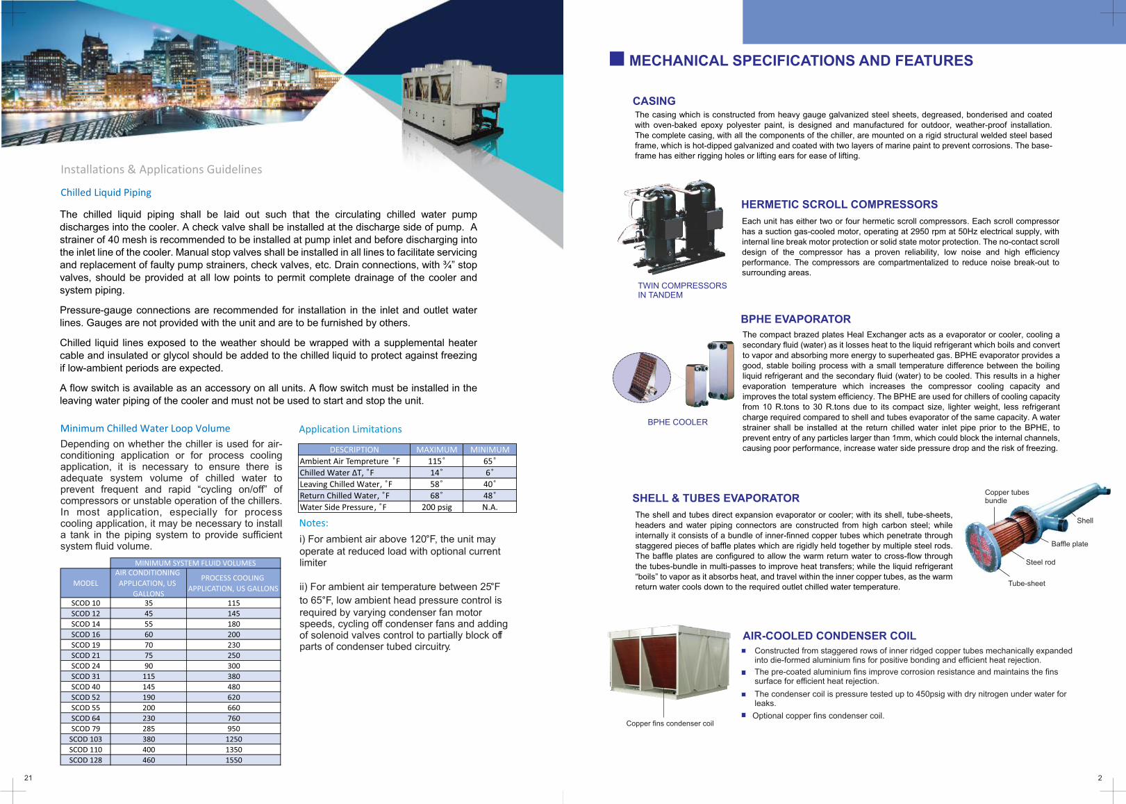
CASINGThe casing which is constructed from heavy gauge galvanized steel sheets, degreased, bonderised and coated with oven-baked epoxy polyester paint, is designed and manufactured for outdoor, weather-proof installation. The complete casing, with all the components of the chiller, are mounted on a rigid structural welded steel based frame, which is hot-dipped galvanized and coated with two layers of marine paint to prevent corrosions. The base-frame has either rigging holes or lifting ears for ease of lifting.
Each unit has either two or four hermetic scroll compressors. Each scroll compressor has a suction gas-cooled motor, operating at 2950 rpm at 50Hz electrical supply, with internal line break motor protection or solid state motor protection. The no-contact scroll design of the compressor has a proven reliability, low noise and high efficiency performance. The compressors are compartmentalized to reduce noise break-out to surrounding areas.
BPHE EVAPORATOR
The compact brazed plates Heal Exchanger acts as a evaporator or cooler, cooling a secondary fluid (water) as it losses heat to the liquid refrigerant which boils and convert to vapor and absorbing more energy to superheated gas. BPHE evaporator provides a good, stable boiling process with a small temperature difference between the boiling liquid refrigerant and the secondary fluid (water) to be cooled. This results in a higher evaporation temperature which increases the compressor cooling capacity and improves the total system efficiency. The BPHE are used for chillers of cooling capacity from 10 R.tons to 30 R.tons due to its compact size, lighter weight, less refrigerant
charge required compared to shell and tubes evaporator of the same capacity. A water strainer shall be installed at the return chilled water inlet pipe prior to the BPHE, to prevent entry of any particles larger than 1mm, which could block the internal channels, causing poor performance, increase water side pressure drop and the risk of freezing.
SHELL & TUBES EVAPORATOR
The shell and tubes direct expansion evaporator or cooler; with its shell, tube-sheets, headers and water piping connectors are constructed from high carbon steel; while internally it consists of a bundle of inner-finned copper tubes which penetrate through staggered pieces of baffle plates which are rigidly held together by multiple steel rods. The baffle plates are configured to allow the warm return water to cross-flow through the tubes-bundle in multi-passes to improve heat transfers; while the liquid refrigerant “boils” to vapor as it absorbs heat, and travel within the inner copper tubes, as the warm return water cools down to the required outlet chilled water temperature.
AIR-COOLED CONDENSER COIL
Constructed from staggered rows of inner ridged copper tubes mechanically expanded into die-formed aluminium fins for positive bonding and efficient heat rejection.
The pre-coated aluminium fins improve corrosion resistance and maintains the fins surface for efficient heat rejection.
The condenser coil is pressure tested up to 450psig with dry nitrogen under water for leaks.
Optional copper fins condenser coil.Copper fins condenser coil
TWIN COMPRESSORS IN TANDEM
BPHE COOLER
Copper tubesbundle
Shell
Baffle plate
Steel rod
Tube-sheet
The chilled liquid piping shall be laid out such that the circulating chilled water pump discharges into the cooler. A check valve shall be installed at the discharge side of pump. A strainer of 40 mesh is recommended to be installed at pump inlet and before discharging into the inlet line of the cooler. Manual stop valves shall be installed in all lines to facilitate servicing and replacement of faulty pump strainers, check valves, etc. Drain connections, with ¾” stop valves, should be provided at all low points to permit complete drainage of the cooler and system piping.
Pressure-gauge connections are recommended for installation in the inlet and outlet water lines. Gauges are not provided with the unit and are to be furnished by others.
Chilled liquid lines exposed to the weather should be wrapped with a supplemental heater cable and insulated or glycol should be added to the chilled liquid to protect against freezing if low-ambient periods are expected.
A flow switch is available as an accessory on all units. A flow switch must be installed in the leaving water piping of the cooler and must not be used to start and stop the unit.
Minimum Chilled Water Loop Volume Application Limitations
Installations & Applications Guidelines
Chilled Liquid Piping
Depending on whether the chiller is used for air-conditioning application or for process coolingapplication, it is necessary to ensure there is adequate system volume of chilled water to prevent frequent and rapid “cycling on/off” ofcompressors or unstable operation of the chillers.In most application, especially for processcooling application, it may be necessary to installa tank in the piping system to provide sufficient system fluid volume.
Notes:
i) For ambient air above 120°F, the unit may operate at reduced load with optional currentlimiter
ii) For ambient air temperature between 25°Fto 65°F, low ambient head pressure control isrequired by varying condenser fan motor speeds, cycling off condenser fans and addingof solenoid valves control to partially block offparts of condenser tubed circuitry.
DESCRIPTION MAXIMUM MINIMUM
Ambient Air Tempreture F 115
65
Chilled Water ΔT, F 14 6
Leaving Chilled Water, F 58 40
Return Chilled Water, F 68 48
Water Side Pressure, F 200 psig N.A.
MODEL
AIR CONDITIONING
APPLICATION, US
GALLONS
PROCESS COOLING
APPLICATION, US GALLONS
SCOD 10 35 115
SCOD 12 45 145
SCOD 14 55 180
SCOD 16 60 200
SCOD 19 70 230
SCOD 21 75 250
SCOD 24 90 300
SCOD 31 115 380
SCOD 40 145 480
SCOD 52 190 620
SCOD 55 200 660
SCOD 64 230 760
SCOD 79 285 950
SCOD 103 380 1250
SCOD 110 400 1350
SCOD 128 460 1550
MINIMUM SYSTEM FLUID VOLUMES
POWER AND CONTROL PANEL
Each chiller is packaged with a power and control panel which is ready to accept rated 3 phase 50Hz electrical supply from a remote mounted isolator.
The power panel is furnished with factory pre-wired and mounted DOL starters for compressors, DOL starters for condenser fan motors. MCBs for compressors and fan motors, external overload protectors for compressors and/or fan motors. Power, alarm and compressor run lights to indicate unit operation status.
The Heart of the control panel is the highly reliable Smart-Advance SA-33 microprocessor based controller with advance compressor management logic for scroll compressors in response to required chilled water inlet set-point temperature.
The Smart-Advance SA-33 controller provides the following safety-protection controls and features:-
Display featuring 3 digits with decimal point, minus sign and icons, making it easier to read the values and check the operating status.
Monitors in/out temperature
High discharge pressure cut-out protection
Low suction pressure cut-out protection
Chilled water anti-freeze protection
Staggered starting of compressors to reduce current inrush
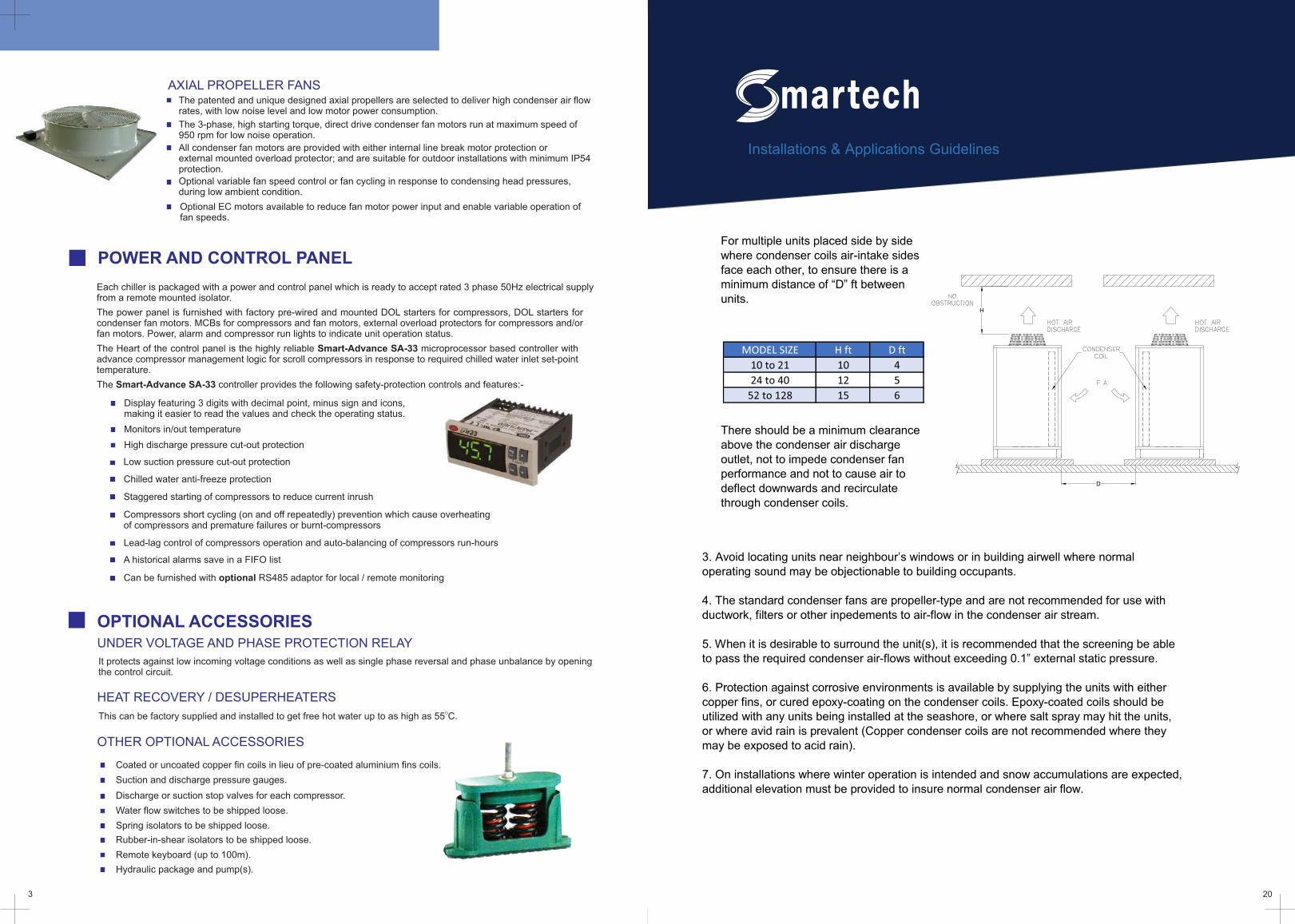
AXIAL PROPELLER FANS The patented and unique designed axial propellers are selected to deliver high condenser air flow rates, with low noise level and low motor power consumption.
The 3-phase, high starting torque, direct drive condenser fan motors run at maximum speed of 950 rpm for low noise operation.
All condenser fan motors are provided with either internal line break motor protection or external mounted overload protector; and are suitable for outdoor installations with minimum IP54 protection.
Optional variable fan speed control or fan cycling in response to condensing head pressures, during low ambient condition.
OPTIONAL ACCESSORIES UNDER VOLTAGE AND PHASE PROTECTION RELAY
HEAT RECOVERY / DESUPERHEATERS
OTHER OPTIONAL ACCESSORIES
OThis can be factory supplied and installed to get free hot water up to as high as 55 C.
Coated or uncoated copper fin coils in lieu of pre-coated aluminium fins coils.
Suction and discharge pressure gauges.
Discharge or suction stop valves for each compressor.
Water flow switches to be shipped loose.
Spring isolators to be shipped loose.
Rubber-in-shear isolators to be shipped loose.
Remote keyboard (up to 100m).
It protects against low incoming voltage conditions as well as single phase reversal and phase unbalance by opening the control circuit.
Hydraulic package and pump(s).
Optional EC motors available to reduce fan motor power input and enable variable operation of fan speeds.
3 20
Compressors short cycling (on and off repeatedly) prevention which cause overheating of compressors and premature failures or burnt-compressors
Lead-lag control of compressors operation and auto-balancing of compressors run-hours
A historical alarms save in a FIFO list
Can be furnished with optional RS485 adaptor for local / remote monitoring
Installations & Applications Guidelines
� For multiple units placed side by side where condenser coils air-intake sides face each other, to ensure there is a minimum distance of “D” ft between units.
� There should be a minimum clearance above the condenser air discharge outlet, not to impede condenser fan performance and not to cause air to deflect downwards and recirculate through condenser coils.
MODEL SIZE H ft D ft
10 to 21 10 4
24 to 40 12 5
52 to 128 15 6
H
D
3. Avoid locating units near neighbour’s windows or in building airwell where normal operating sound may be objectionable to building occupants. 4. The standard condenser fans are propeller-type and are not recommended for use with ductwork, filters or other inpedements to air-flow in the condenser air stream. 5. When it is desirable to surround the unit(s), it is recommended that the screening be able to pass the required condenser air-flows without exceeding 0.1” external static pressure. 6. Protection against corrosive environments is available by supplying the units with either copper fins, or cured epoxy-coating on the condenser coils. Epoxy-coated coils should be utilized with any units being installed at the seashore, or where salt spray may hit the units, or where avid rain is prevalent (Copper condenser coils are not recommended where they may be exposed to acid rain). 7. On installations where winter operation is intended and snow accumulations are expected, additional elevation must be provided to insure normal condenser air flow.
4
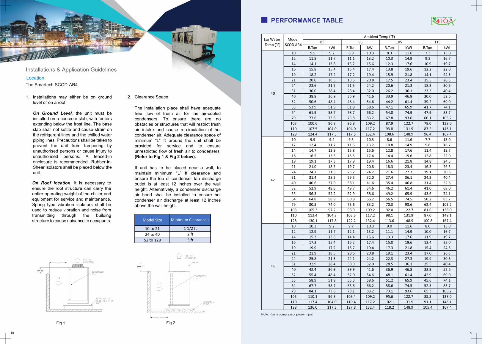
Note: Kwi is compressor power input
19
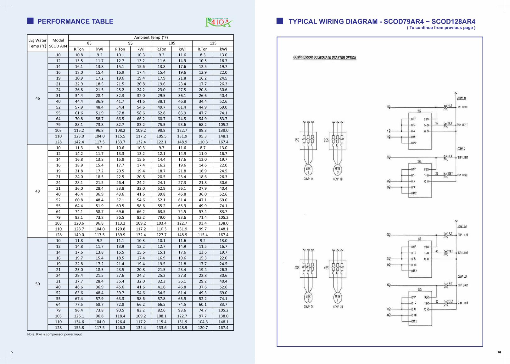
PERFORMANCE TABLE
Installations & Application Guidelines
1. Installations may either be on ground level or on a roof On Ground Level, the unit must be installed on a concrete slab, with footers extending below the frost line. The base slab shall not settle and cause strain on the refrigerant lines and the chilled water piping lines. Precautions shall be taken to prevent the unit from tampering by unauthorised persons or cause injury to unauthorised persons. A fenced-in enclosure is recommended. Rubber-in-Shear isolators shall be placed below the unit.
Location
The Smartech SCOD-AR4
On Roof location, it is necessary to ensure the roof structure can carry the entire operating weight of the chiller and equipment for service and maintenance. Spring type vibration isolators shall be used to reduce vibration and noise from transmitting through the building structure to cause nuisance to occupants.
2. Clearance Space
� The installation place shall have adequate free flow of fresh air for the air-cooled condensers. To ensure there are no obstacles or structures that will restrict fresh air intake and cause re-circulation of hot condenser air. Adequate clearance space of minimum “L” ft around the unit shall be provided for service and to ensure unrestricted flow of fresh air to condensers. (Refer to Fig 1 & Fig 2 below).
� If unit has to be placed near a wall, to maintain minimum “L” ft clearance and ensure the top of condenser fan discharge outlet is at least 12 inches over the wall height. Alternatively, a condenser discharge air hood shall be installed to ensure hot condenser air discharge at least 12 inches above the wall height.
Model Size
10 to 21
24 to 40
52 to 128
Minimum Clearance L
1 1/2 ft
2 ft
3 ft
MIN 12"
L
MIN 12"
L
R.Ton kWi R.Ton kWi R.Ton kWi R.Ton kWi
10 9.5 9.2 8.9 10.3 8.3 11.6 7.3 13.0
12 11.8 11.7 11.1 13.2 10.3 14.9 9.2 16.7
14 14.1 13.8 13.2 15.6 12.3 17.6 10.9 19.7
16 15.8 15.4 15.4 17.4 13.8 19.6 12.2 22.0
19 18.2 17.2 17.2 19.4 15.9 21.8 14.1 24.5
21 20.0 18.5 18.5 20.8 17.5 23.4 15.5 26.3
24 23.6 21.5 21.5 24.2 20.6 21.3 18.3 30.6
31 30.0 28.4 28.4 32.0 26.2 36.1 23.3 40.4
40 38.8 36.9 36.9 41.6 33.9 46.8 30.0 52.6
52 50.6 48.4 48.4 54.6 44.2 61.4 39.2 69.0
55 53.9 51.9 51.9 58.6 47.1 65.9 41.7 74.1
64 61.9 58.7 58.7 66.2 54.0 74.9 47.9 83.7
79 77.6 73.8 73.8 83.2 67.8 93.6 60.1 105.2
103 100.6 96.8 96.8 109.2 87.9 122.7 78.0 138.0
110 107.5 104.0 104.0 117.2 93.8 131.9 83.2 148.1
128 124.4 117.5 117.5 132.4 108.6 148.9 96.4 167.4
10 9.9 9.2 9.3 10.3 8.6 11.6 7.7 13.0
12 12.4 11.7 11.6 13.2 10.8 14.9 9.6 16.7
14 14.7 13.9 13.8 15.6 12.8 17.6 11.4 19.7
16 16.5 15.5 15.5 17.4 14.4 19.6 12.8 22.0
19 19.1 17.3 17.9 19.4 16.6 21.8 14.8 24.5
21 21.0 18.5 19.7 20.8 18.3 23.4 16.3 26.3
24 24.7 21.5 23.2 24.2 21.6 27.3 19.1 30.6
31 31.4 28.5 29.5 32.0 27.4 36.1 24.3 40.4
40 40.6 37.0 38.1 41.6 35.4 46.8 31.4 52.6
52 52.9 48.6 49.7 54.6 46.2 61.4 41.0 69.0
55 56.3 52.2 52.9 58.6 49.2 65.9 43.6 74.1
64 64.8 58.9 60.8 66.2 56.5 74.5 50.2 83.7
79 80.5 74.0 75.6 83.2 70.3 93.6 62.4 105.2
103 105.3 97.2 98.9 109.2 92.0 122.7 81.6 138.0
110 112.4 104.3 105.5 117.2 98.1 131.9 87.0 148.1
128 130.1 117.8 122.2 132.4 113.6 148.9 100.8 167.4
10 10.3 9.2 9.7 10.3 9.0 11.6 8.0 13.0
12 12.9 11.7 12.1 13.2 11.1 14.9 10.0 16.7
14 15.3 13.8 14.4 15.6 13.3 17.6 11.9 19.7
16 17.3 15.4 16.2 17.4 15.0 19.6 13.4 22.0
19 19.9 17.2 18.7 19.4 17.3 21.8 15.4 24.5
21 21.9 18.5 20.6 20.8 19.1 23.4 17.0 26.3
24 25.8 21.5 24.1 24.2 22.3 27.3 19.9 30.6
31 32.9 28.4 30.9 32.0 28.5 36.1 25.5 40.4
40 42.4 36.9 39.9 41.6 36.9 46.8 32.9 52.6
52 55.4 48.4 52.0 54.6 48.1 61.4 42.9 69.0
55 58.9 51.9 55.3 58.6 51.2 65.9 45.6 74.1
64 67.7 58.7 63.6 66.2 58.6 74.5 52.5 83.7
79 84.1 73.8 79.1 83.2 73.1 93.6 65.3 105.2
103 110.1 96.8 103.4 109.2 95.6 122.7 85.3 138.0
110 117.4 104.0 110.4 117.2 102.1 131.9 91.1 148.1
128 136.0 117.5 127.8 132.4 118.2 148.9 105.4 167.4
Ambient Temp (°F)
85 95 105 115
40
42
44
Lvg Water
Temp (°F)
Model
SCOD AR4
Fig 1 Fig 2
5 1418
PERFORMANCE TABLE
Note: Kwi is compressor power input
R.Ton kWi R.Ton kWi R.Ton kWi R.Ton kWi
10 10.8 9.2 10.1 10.3 9.2 11.6 8.3 13.0
12 13.5 11.7 12.7 13.2 11.6 14.9 10.5 16.7
14 16.1 13.8 15.1 15.6 13.8 17.6 12.5 19.7
16 18.0 15.4 16.9 17.4 15.4 19.6 13.9 22.0
19 20.9 17.2 19.6 19.4 17.9 21.8 16.2 24.5
21 22.9 18.5 21.5 20.8 19.6 23.4 17.7 26.3
24 26.8 21.5 25.2 24.2 23.0 27.5 20.8 30.6
31 34.4 28.4 32.3 32.0 29.5 36.1 26.6 40.4
40 44.4 36.9 41.7 41.6 38.1 46.8 34.4 52.6
52 57.9 48.4 54.4 54.6 49.7 61.4 44.9 69.0
55 61.6 51.9 57.8 58.6 52.8 65.9 47.7 74.1
64 70.8 58.7 66.5 66.2 60.7 74.5 54.9 83.7
79 88.1 73.8 82.7 83.2 75.5 93.6 68.2 105.2
103 115.2 96.8 108.2 109.2 98.8 122.7 89.3 138.0
110 123.0 104.0 115.5 117.2 105.5 131.9 95.3 148.1
128 142.4 117.5 133.7 132.4 122.1 148.9 110.3 167.4
10 11.3 9.2 10.6 10.3 9.7 11.6 8.7 13.0
12 14.2 11.7 13.3 13.2 12.1 14.9 11.0 16.7
14 16.8 13.8 15.8 15.6 14.4 17.6 13.0 19.7
16 18.9 15.4 17.7 17.4 16.2 19.6 14.6 22.0
19 21.8 17.2 20.5 19.4 18.7 21.8 16.9 24.5
21 24.0 18.5 22.5 20.8 20.5 23.4 18.6 26.3
24 28.1 21.5 26.4 24.2 24.1 27.3 21.8 30.6
31 36.0 28.4 33.8 32.0 52.9 36.1 27.9 40.4
40 46.4 36.9 43.6 41.6 39.8 46.8 36.0 52.6
52 60.8 48.4 57.1 54.6 52.1 61.4 47.1 69.0
55 64.4 51.9 60.5 58.6 55.2 65.9 49.9 74.1
64 74.1 58.7 69.6 66.2 63.5 74.5 57.4 83.7
79 92.1 73.8 86.5 83.2 79.0 93.6 71.4 105.2
103 120.6 96.8 113.2 109.2 103.4 122.7 93.4 138.0
110 128.7 104.0 120.8 117.2 110.3 131.9 99.7 148.1
128 149.0 117.5 139.9 132.4 127.7 148.9 115.4 167.4
10 11.8 9.2 11.1 10.3 10.1 11.6 9.2 13.0
12 14.8 11.7 13.9 13.2 12.7 14.9 11.5 16.7
14 17.6 13.8 16.5 15.6 15.1 17.6 13.6 19.7
16 19.7 15.4 18.5 17.4 16.9 19.6 15.3 22.0
19 22.8 17.2 21.4 19.4 19.5 21.8 17.7 24.5
21 25.0 18.5 23.5 20.8 21.5 23.4 19.4 26.3
24 29.4 21.5 27.6 24.2 25.2 27.3 22.8 30.6
31 37.7 28.4 35.4 32.0 32.3 36.1 29.2 40.4
40 48.6 36.9 45.6 41.6 41.6 46.8 37.6 52.6
52 63.6 48.4 59.7 54.6 54.5 61.4 49.3 69.0
55 67.4 57.9 63.3 58.6 57.8 65.9 52.2 74.1
64 77.5 58.7 72.8 66.2 66.5 74.5 60.1 83.7
79 96.4 73.8 90.5 83.2 82.6 93.6 74.7 105.2
103 126.1 96.8 118.4 109.2 108.1 122.7 97.7 138.0
110 134.6 104.0 126.4 117.2 115.4 131.9 104.3 148.1
128 155.8 117.5 146.3 132.4 133.6 148.9 120.7 167.4
Ambient Temp (°F)
85 95 105 115
46
48
50
Lvg Water
Temp (°F)
Model
SCOD AR4
TYPICAL WIRING DIAGRAM - SCOD79AR4 ~ SCOD128AR4 ( To continue from previous page )
6
Notes:(I) NRA - running amperes at nominal conditions(ii) MTA - must trip amperes of compressor(iii) MCA - Minimum Circuit Ampacity(iv) MFS - Maximum Fuse Size(v) Unit electrical data excludes optional chilled water pump
17
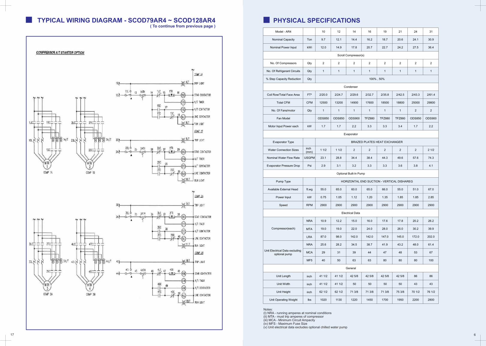
PHYSICAL SPECIFICATIONS TYPICAL WIRING DIAGRAM - SCOD79AR4 ~ SCOD128AR4 ( To continue from previous page )
Model - AR4 10 12 14 16 19 21 24 31
Nominal Capacity Ton 9.7 12.1 14.4 16.2 18.7 20.6 24.1 30.9
Nominal Power Input kWi 12.0 14.9 17.8 20.7 22.7 24.2 27.5 36.4
No. Of Compressors Qty 2 2 2 2 2 2 2 2
No. Of Refrigerant Circuits Qty 1 1 1 1 1 1 1 1
% Step Capacity Reduction Qty
Coil Row/Total Face Area FT² 2/20.0 2/24.7 2/29.6 2/32.7 2/35.8 2/42.5 2/43.3 2/61.4
Total CFM CFM 12500 13200 14900 17600 18500 18800 25000 29800
No. Of Fans/motor Qty 1 1 1 1 1 1 2 2
Fan Model ODS850 ODS850 ODS900 TFZ880 TFZ880 TFZ880 ODS850 ODS900
Motor Input Power each kW 1.7 1.7 2.2 3.3 3.3 3.4 1.7 2.2
Evaporator Type
Water Connection Sizesinch (mm)
1 1/2 1 1/2 2 2 2 2 2 2 1/2
Nominal Water Flow Rate USGPM 23.1 28.8 34.4 38.4 44.3 49.6 57.6 74.3
Evaporator Pressure Drop Psi 2.9 3.1 3.2 3.3 3.3 3.6 3.8 4.1
Pump Type
Available External Head ft.wg 55.0 65.0 60.0 65.0 66.0 55.0 51.0 67.0
Power Input kW 0.75 1.05 1.12 1.20 1.35 1.85 1.85 2.85
Speed RPM 2900 2900 2900 2900 2900 2900 2900 2900
NRA 10.9 12.2 15.0 16.0 17.6 17.8 20.2 26.2
MTA 19.0 19.0 22.0 24.0 28.0 26.0 30.2 39.9
LRA 87.0 98.0 142.0 142.0 147.0 145.0 172.0 202.0
NRA 25.6 28.2 34.5 38.7 41.9 43.2 48.0 61.4
MCA 29 31 39 44 47 48 53 67
MF5 40 50 63 63 80 80 80 100
Unit Length inch 41 1/2 41 1/2 42 5/8 42 5/8 42 5/8 42 5/8 86 86
Unit Width inch 41 1/2 41 1/2 50 50 50 50 43 43
Unit Height inch 62 1/2 62 1/2 71 3/8 71 3/8 71 3/8 75 3/8 70 1/2 76 1/2
Unit Operating Weight lbs 1020 1130 1220 1450 1700 1950 2200 2800
BRAZED PLATES HEAT EXCHANGER
Scroll Compressor(s)
Electrical Data
General
Compressor(each)
100% , 50%
Condenser
Evaporator
Optional Built-In Pump
HORIZONTAL END SUCTION - VERTICAL DISHAREG
Unit Electrical Data excluding optional pump
7 16
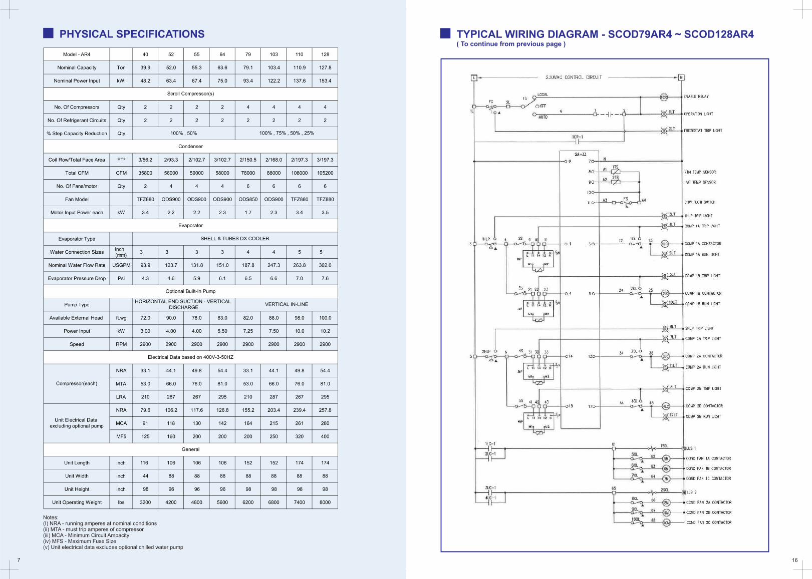
Notes:(I) NRA - running amperes at nominal conditions(ii) MTA - must trip amperes of compressor(iii) MCA - Minimum Circuit Ampacity(iv) MFS - Maximum Fuse Size(v) Unit electrical data excludes optional chilled water pump
PHYSICAL SPECIFICATIONS TYPICAL WIRING DIAGRAM - SCOD79AR4 ~ SCOD128AR4 ( To continue from previous page )
Model - AR4 40 52 55 64 79 103 110 128
Nominal Capacity Ton 39.9 52.0 55.3 63.6 79.1 103.4 110.9 127.8
Nominal Power Input kWi 48.2 63.4 67.4 75.0 93.4 122.2 137.6 153.4
No. Of Compressors Qty 2 2 2 2 4 4 4 4
No. Of Refrigerant Circuits Qty 2 2 2 2 2 2 2 2
% Step Capacity Reduction Qty
Coil Row/Total Face Area FT² 3/56.2 2/93.3 2/102.7 3/102.7 2/150.5 2/168.0 2/197.3 3/197.3
Total CFM CFM 35800 56000 59000 58000 78000 88000 108000 105200
No. Of Fans/motor Qty 2 4 4 4 6 6 6 6
Fan Model TFZ880 ODS900 ODS900 ODS900 ODS850 ODS900 TFZ880 TFZ880
Motor Input Power each kW 3.4 2.2 2.2 2.3 1.7 2.3 3.4 3.5
Evaporator Type
Water Connection Sizesinch (mm)
3 3 3 3 4 4 5 5
Nominal Water Flow Rate USGPM 93.9 123.7 131.8 151.0 187.8 247.3 263.8 302.0
Evaporator Pressure Drop Psi 4.3 4.6 5.9 6.1 6.5 6.6 7.0 7.6
Pump Type
Available External Head ft.wg 72.0 90.0 78.0 83.0 82.0 88.0 98.0 100.0
Power Input kW 3.00 4.00 4.00 5.50 7.25 7.50 10.0 10.2
Speed RPM 2900 2900 2900 2900 2900 2900 2900 2900
NRA 33.1 44.1 49.8 54.4 33.1 44.1 49.8 54.4
MTA 53.0 66.0 76.0 81.0 53.0 66.0 76.0 81.0
LRA 210 287 267 295 210 287 267 295
NRA 79.6 106.2 117.6 126.8 155.2 203.4 239.4 257.8
MCA 91 118 130 142 164 215 261 280
MF5 125 160 200 200 200 250 320 400
Unit Length inch 116 106 106 106 152 152 174 174
Unit Width inch 44 88 88 88 88 88 88 88
Unit Height inch 98 96 96 96 98 98 98 98
Unit Operating Weight lbs 3200 4200 4800 5600 6200 6800 7400 8000
SHELL & TUBES DX COOLER
Optional Built-In Pump
HORIZONTAL END SUCTION - VERTICAL DISCHARGE
VERTICAL IN-LINE
Scroll Compressor(s)
100% , 50% 100% , 75% , 50% , 25%
Condenser
Evaporator
General
Unit Electrical Data excluding optional pump
Electrical Data based on 400V-3-50HZ
Compressor(each)
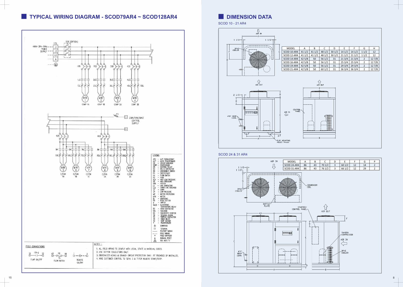
SCOD 10 - 21 AR4
SCOD 24 & 31 AR4
8
DIMENSION DATA
15
TYPICAL WIRING DIAGRAM - SCOD79AR4 ~ SCOD128AR4
MODEL A B C D E F G H
SCOD 10-AR4 41 1/2 41 1/2 48 1/2 30 1/2 14 1/2 14 1/2 1 1/2 12
SCOD 12-AR4 41 1/2 41 1/2 48 1/2 30 1/2 21 1/2 21 1/2 1 1/2 12
SCOD 14-AR4 42 5/8 50 56 1/2 31 21 3/4 21 3/4 2 12 7/8
SCOD 16-AR4 42 5/8 50 56 1/2 31 25 3/4 25 3/4 2 12 7/8
SCOD 19-AR4 42 5/8 50 56 1/2 31 29 3/4 29 3/4 2 12 7/8
SCOD 21-AR4 42 5/8 50 60 1/2 31 36 3/4 36 3/4 2 12 7/8
MODEL A B C D E F G P
SCOD 24-AR4 86 43 70 1/2 3 60 1/2 12 14 2
SCOD 31-AR4 86 43 76 1/2 3 66 1/2 12 29 2
9 14
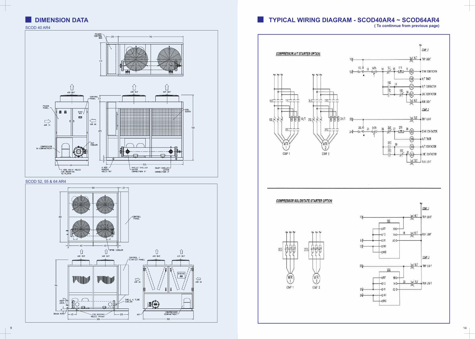
SCOD 40 AR4
SCOD 52, 55 & 64 AR4
DIMENSION DATA TYPICAL WIRING DIAGRAM - SCOD40AR4 ~ SCOD64AR4 ( To continnue from previous page)
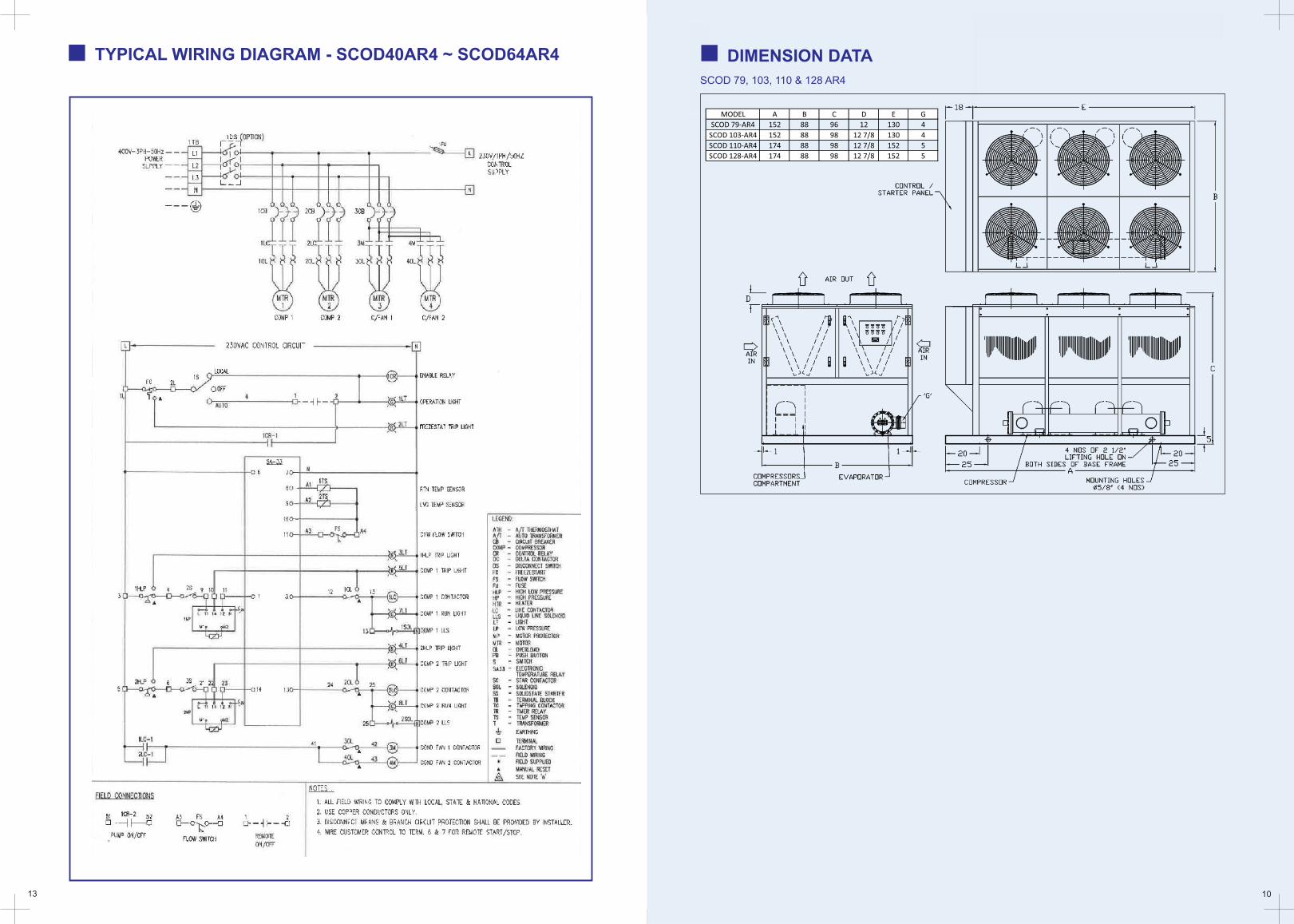
13 10
SCOD 79, 103, 110 & 128 AR4
DIMENSION DATA TYPICAL WIRING DIAGRAM - SCOD40AR4 ~ SCOD64AR4 DIMENSION DATA
SCOD 79, 103, 110 & 128 AR4
MODEL A B C D E G
SCOD 79-AR4 152 88 96 12 130 4
SCOD 103-AR4 152 88 98 12 7/8 130 4
SCOD 110-AR4 174 88 98 12 7/8 152 5
SCOD 128-AR4 174 88 98 12 7/8 152 5
11 12
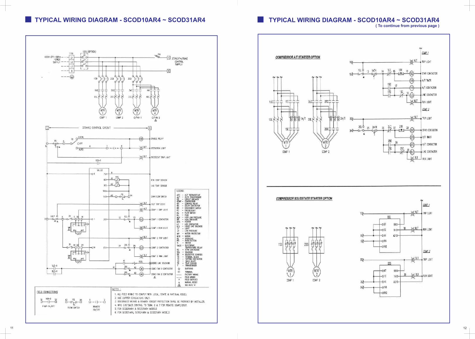
TYPICAL WIRING DIAGRAM - SCOD10AR4 ~ SCOD31AR4 TYPICAL WIRING DIAGRAM - SCOD10AR4 ~ SCOD31AR4 ( To continue from previous page )
Related Documents