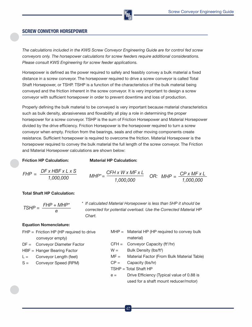
47 Screw Conveyor Engineering Guide SCREW CONVEYOR HORSEPOWER The calculations included in the KWS Screw Conveyor Engineering Guide are for control fed screw conveyors only. The horsepower calculations for screw feeders require additional considerations. Please consult KWS Engineering for screw feeder applications. Horsepower is defined as the power required to safely and feasibly convey a bulk material a fixed distance in a screw conveyor The horsepower required to drive a screw conveyor is called Total Shaft Horsepower, or TSHP TSHP is a function of the characteristics of the bulk material being conveyed and the friction inherent in the screw conveyor It is very important to design a screw conveyor with sufficient horsepower in order to prevent downtime and loss of production Properly defining the bulk material to be conveyed is very important because material characteristics such as bulk density, abrasiveness and flowability all play a role in determining the proper horsepower for a screw conveyor TSHP is the sum of Friction Horsepower and Material Horsepower divided by the drive efficiency Friction Horsepower is the horsepower required to turn a screw conveyor when empty Friction from the bearings, seals and other moving components create resistance Sufficient horsepower is required to overcome the friction Material Horsepower is the horsepower required to convey the bulk material the full length of the screw conveyor The Friction and Material Horsepower calculations are shown below: Friction HP Calculation: Material HP Calculation: Total Shaft HP Calculation: * If calculated Material Horsepower is less than 5HP it should be corrected for potential overload. Use the Corrected Material HP Chart. Equation Nomenclature: FHP = Friction HP (HP required to drive conveyor empty) DF = Conveyor Diameter Factor HBF = Hanger Bearing Factor L = Conveyor Length (feet) S = Conveyor Speed (RPM) MHP = Material HP (HP required to convey bulk material) CFH = Conveyor Capacity (ft 3 /hr) W = Bulk Density (lbs/ft 3 ) MF = Material Factor (From Bulk Material Table) CP = Capacity (lbs/hr) TSHP = Total Shaft HP e = Drive Efficiency (Typical value of 088 is used for a shaft mount reducer/motor)

Welcome message from author
This document is posted to help you gain knowledge. Please leave a comment to let me know what you think about it! Share it to your friends and learn new things together.
Transcript
47
DesignEngineeringManufacturing
Screw Conveyor Engineering Guide
sCReW COnVeYOR HORsePOWeR
The calculations included in the KWS Screw Conveyor Engineering Guide are for control fed screw
conveyors only. The horsepower calculations for screw feeders require additional considerations.
Please consult KWS Engineering for screw feeder applications.
Horsepower is defined as the power required to safely and feasibly convey a bulk material a fixed
distance in a screw conveyor . The horsepower required to drive a screw conveyor is called Total
Shaft Horsepower, or TSHp . TSHp is a function of the characteristics of the bulk material being
conveyed and the friction inherent in the screw conveyor . it is very important to design a screw
conveyor with sufficient horsepower in order to prevent downtime and loss of production .
properly defining the bulk material to be conveyed is very important because material characteristics
such as bulk density, abrasiveness and flowability all play a role in determining the proper
horsepower for a screw conveyor . TSHp is the sum of friction Horsepower and Material Horsepower
divided by the drive efficiency . friction Horsepower is the horsepower required to turn a screw
conveyor when empty . friction from the bearings, seals and other moving components create
resistance . Sufficient horsepower is required to overcome the friction . Material Horsepower is the
horsepower required to convey the bulk material the full length of the screw conveyor . The friction
and Material Horsepower calculations are shown below:
friction Hp Calculation: Material Hp Calculation:
Total Shaft Hp Calculation:
* If calculated Material Horsepower is less than 5HP it should be
corrected for potential overload. Use the Corrected Material HP
Chart.
Equation Nomenclature:
fHp = friction Hp (Hp required to drive
conveyor empty)
df = Conveyor diameter factor
HBf = Hanger Bearing factor
L = Conveyor Length (feet)
S = Conveyor Speed (rpM)
MHp = Material Hp (Hp required to convey bulk
material)
CfH = Conveyor Capacity (ft3/hr)
w = Bulk density (lbs/ft3)
Mf = Material factor (from Bulk Material Table)
Cp = Capacity (lbs/hr)
TSHp = Total Shaft Hp
e = drive Efficiency (Typical value of 0 .88 is
used for a shaft mount reducer/motor)
DesignEngineeringManufacturing
48
Screw Conveyor Engineering Guide
sCReW COnVeYOR HORsePOWeR
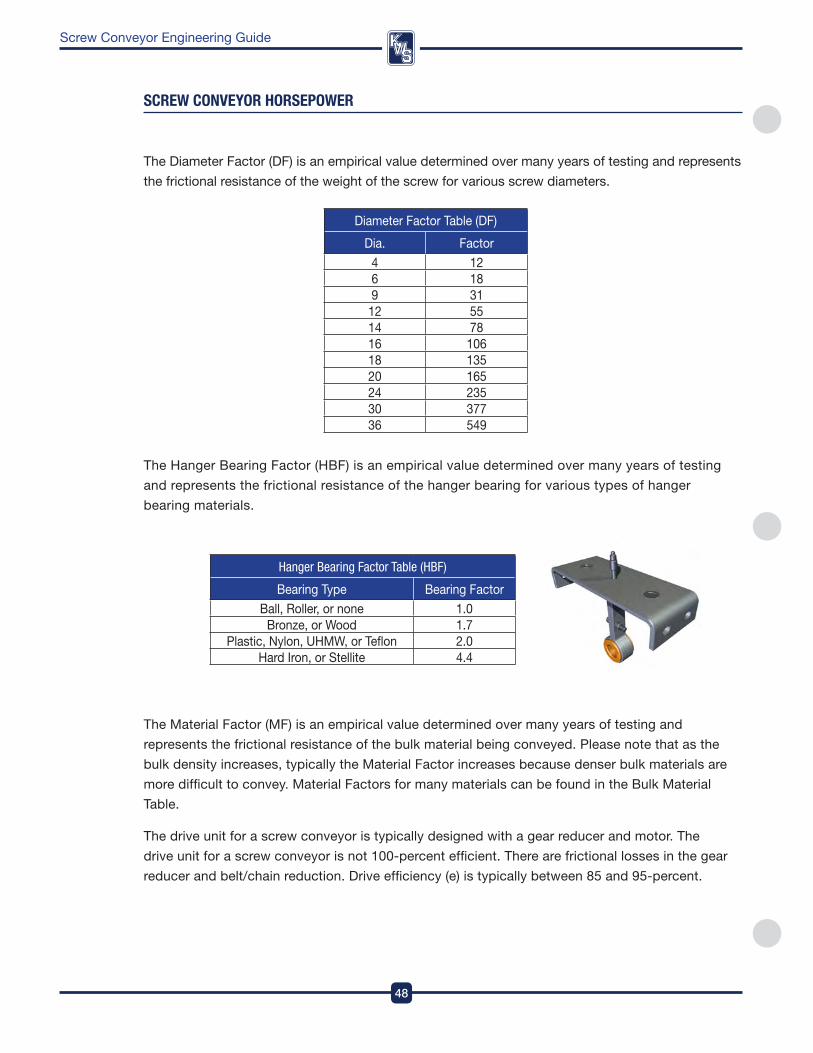
Hanger Bearing Factor Table (HBF)
Bearing Type Bearing factor
Ball, roller, or none 1 .0Bronze, or wood 1 .7
plastic, nylon, UHMw, or Teflon 2 .0Hard iron, or Stellite 4 .4
diameter factor Table (df)
dia . factor
4 126 189 31
12 5514 7816 10618 13520 16524 23530 37736 549
The diameter factor (df) is an empirical value determined over many years of testing and represents
the frictional resistance of the weight of the screw for various screw diameters .
The Hanger Bearing factor (HBf) is an empirical value determined over many years of testing
and represents the frictional resistance of the hanger bearing for various types of hanger
bearing materials .
The Material factor (Mf) is an empirical value determined over many years of testing and
represents the frictional resistance of the bulk material being conveyed . please note that as the
bulk density increases, typically the Material factor increases because denser bulk materials are
more difficult to convey . Material factors for many materials can be found in the Bulk Material
Table .
The drive unit for a screw conveyor is typically designed with a gear reducer and motor . The
drive unit for a screw conveyor is not 100-percent efficient . There are frictional losses in the gear
reducer and belt/chain reduction . drive efficiency (e) is typically between 85 and 95-percent .
49
DesignEngineeringManufacturing
Screw Conveyor Engineering Guide
Calculated HP
0 0.5 1 1.5 2 2.5 3 3.5 4 4.5 5
Cor
rect
ed H
P
5
4.5
4
3.5
3
2.5
2
1.5
1
0.5
0
Corrected Material Hp Chart
sCReW COnVeYOR HORsePOWeR
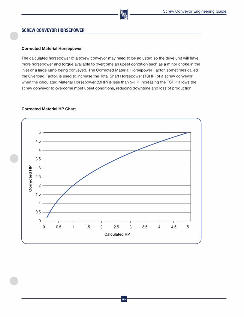
Corrected Material Horsepower
The calculated horsepower of a screw conveyor may need to be adjusted so the drive unit will have
more horsepower and torque available to overcome an upset condition such as a minor choke in the
inlet or a large lump being conveyed . The Corrected Material Horsepower factor, sometimes called
the overload factor, is used to increase the Total Shaft Horsepower (TSHp) of a screw conveyor
when the calculated Material Horsepower (MHp) is less than 5-Hp . increasing the TSHp allows the
screw conveyor to overcome most upset conditions, reducing downtime and loss of production .
DesignEngineeringManufacturing
50
Screw Conveyor Engineering Guide
sCReW COnVeYOR HORsePOWeR
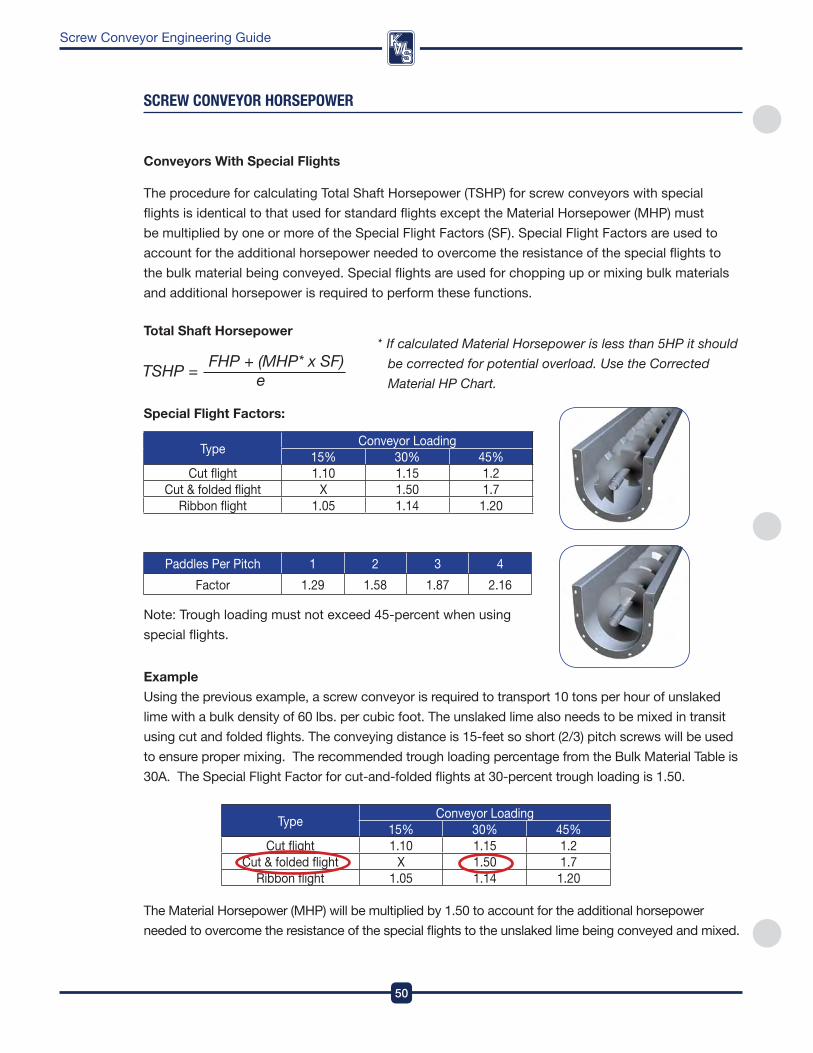
Conveyors With Special flights
The procedure for calculating Total Shaft Horsepower (TSHp) for screw conveyors with special
flights is identical to that used for standard flights except the Material Horsepower (MHp) must
be multiplied by one or more of the Special flight factors (Sf) . Special flight factors are used to
account for the additional horsepower needed to overcome the resistance of the special flights to
the bulk material being conveyed . Special flights are used for chopping up or mixing bulk materials
and additional horsepower is required to perform these functions .
Total Shaft Horsepower * If calculated Material Horsepower is less than 5HP it should
be corrected for potential overload. Use the Corrected
Material HP Chart.
Special flight factors:
TypeConveyor Loading
15% 30% 45%Cut flight 1 .10 1 .15 1 .2
Cut & folded flight X 1 .50 1 .7ribbon flight 1 .05 1 .14 1 .20
paddles per pitch 1 2 3 4
factor 1 .29 1 .58 1 .87 2 .16
note: Trough loading must not exceed 45-percent when using
special flights .
Example
Using the previous example, a screw conveyor is required to transport 10 tons per hour of unslaked
lime with a bulk density of 60 lbs . per cubic foot . The unslaked lime also needs to be mixed in transit
using cut and folded flights . The conveying distance is 15-feet so short (2/3) pitch screws will be used
to ensure proper mixing . The recommended trough loading percentage from the Bulk Material Table is
30a . The Special flight factor for cut-and-folded flights at 30-percent trough loading is 1 .50 .
The Material Horsepower (MHp) will be multiplied by 1 .50 to account for the additional horsepower
needed to overcome the resistance of the special flights to the unslaked lime being conveyed and mixed .
TypeConveyor Loading
15% 30% 45%Cut flight 1 .10 1 .15 1 .2
Cut & folded flight X 1 .50 1 .7ribbon flight 1 .05 1 .14 1 .20
51
DesignEngineeringManufacturing
Screw Conveyor Engineering Guide
sCReW COnVeYOR TORqUe
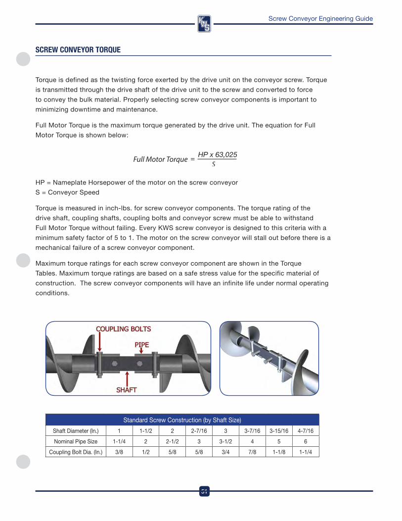
Torque is defined as the twisting force exerted by the drive unit on the conveyor screw . Torque
is transmitted through the drive shaft of the drive unit to the screw and converted to force
to convey the bulk material . properly selecting screw conveyor components is important to
minimizing downtime and maintenance .
full Motor Torque is the maximum torque generated by the drive unit . The equation for full
Motor Torque is shown below:
Hp = nameplate Horsepower of the motor on the screw conveyor
S = Conveyor Speed
Torque is measured in inch-lbs . for screw conveyor components . The torque rating of the
drive shaft, coupling shafts, coupling bolts and conveyor screw must be able to withstand
full Motor Torque without failing . Every kwS screw conveyor is designed to this criteria with a
minimum safety factor of 5 to 1 . The motor on the screw conveyor will stall out before there is a
mechanical failure of a screw conveyor component .
Maximum torque ratings for each screw conveyor component are shown in the Torque
Tables . Maximum torque ratings are based on a safe stress value for the specific material of
construction . The screw conveyor components will have an infinite life under normal operating
conditions .
Standard Screw Construction (by Shaft Size)
Shaft diameter (in .) 1 1-1/2 2 2-7/16 3 3-7/16 3-15/16 4-7/16
nominal pipe Size 1-1/4 2 2-1/2 3 3-1/2 4 5 6
Coupling Bolt dia . (in .) 3/8 1/2 5/8 5/8 3/4 7/8 1-1/8 1-1/4
DesignEngineeringManufacturing
52
Screw Conveyor Engineering Guide
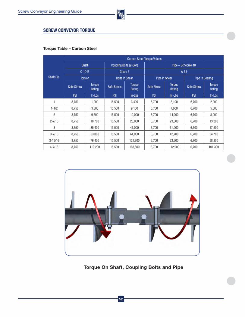
sCReW COnVeYOR TORqUe
Shaft Dia.
Carbon Steel Torque Values
Shaft Coupling Bolts (2-Bolt) Pipe – Schedule 40
C-1045 Grade 5 A-53
Torsion Bolts in Shear Pipe in Shear Pipe in Bearing
Safe StressTorque Rating
Safe StressTorque Rating
Safe StressTorque Rating
Safe StressTorque Rating
PSI In-Lbs PSI In-Lbs PSI In-Lbs PSI In-Lbs
1 8,750 1,000 15,500 3,400 6,700 3,100 6,700 2,200
1-1/2 8,750 3,800 15,500 9,100 6,700 7,600 6,700 5,600
2 8,750 9,500 15,500 19,000 6,700 14,200 6,700 8,900
2-7/16 8,750 18,700 15,500 23,000 6,700 23,000 6,700 13,200
3 8,750 35,400 15,500 41,000 6,700 31,900 6,700 17.500
3-7/16 8,750 53,000 15,500 64,000 6,700 42,700 6,700 24,700
3-15/16 8,750 76,400 15,500 121,300 6,700 72,600 6,700 58,200
4-7/16 8,750 110,200 15,500 168,800 6,700 112,900 6,700 101,300
Torque Table – Carbon Steel
Torque on Shaft, Coupling Bolts and pipe
53
DesignEngineeringManufacturing
Screw Conveyor Engineering Guide
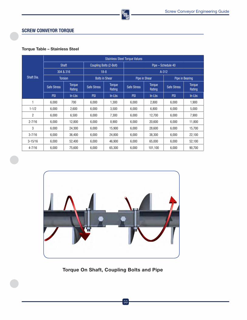
sCReW COnVeYOR TORqUe
Shaft Dia.
Stainless Steel Torque Values
Shaft Coupling Bolts (2-Bolt) Pipe – Schedule 40
304 & 316 18-8 A-312
Torsion Bolts in Shear Pipe in Shear Pipe in Bearing
Safe StressTorque Rating
Safe StressTorque Rating
Safe StressTorque Rating
Safe StressTorque Rating
PSI In-Lbs PSI In-Lbs PSI In-Lbs PSI In-Lbs
1 6,000 700 6,000 1,300 6,000 2,800 6,000 1,900
1-1/2 6,000 2,600 6,000 3,500 6,000 6,800 6,000 5,000
2 6,000 6,500 6,000 7,300 6,000 12,700 6,000 7,900
2-7/16 6,000 12,800 6,000 8,900 6,000 20,600 6,000 11,800
3 6,000 24,300 6,000 15,900 6,000 28,600 6,000 15,700
3-7/16 6,000 36,400 6,000 24,800 6,000 38,300 6,000 22,100
3-15/16 6,000 52,400 6,000 46,900 6,000 65,000 6,000 52,100
4-7/16 6,000 75,600 6,000 65,300 6,000 101,100 6,000 90,700
Torque Table – Stainless Steel
Torque on Shaft, Coupling Bolts and pipe
DesignEngineeringManufacturing
54
Screw Conveyor Engineering Guide
sCReW COnVeYOR eXaMPle
There are many different factors to consider when designing a screw conveyor . The purpose of this
example is to provide a step-by-step process that a kwS engineer would follow when designing
a screw conveyor . it is important for the person designing the screw conveyor to understand how
each factor affects the final screw conveyor design .
The following information will be used for the example –• BulkMaterial:CornMeal• Capacity:25,600lbs/hr• ScrewConveyorLength:16-feet,0-inchesfromcenterlineofinlettocenterlineofdischarge
• ScrewConveyorDegreeofIncline:0°Horizontal
The screw conveyor for the example is control fed at the inlet by another screw conveyor .
SCREW CoNVEYoR ExAMplE - STEp 1:
ESTABlISH CHARACTERISTICS of BUlK MATERIAl
The first step is to look up corn meal in the Bulk Material Table and write down the following
information –
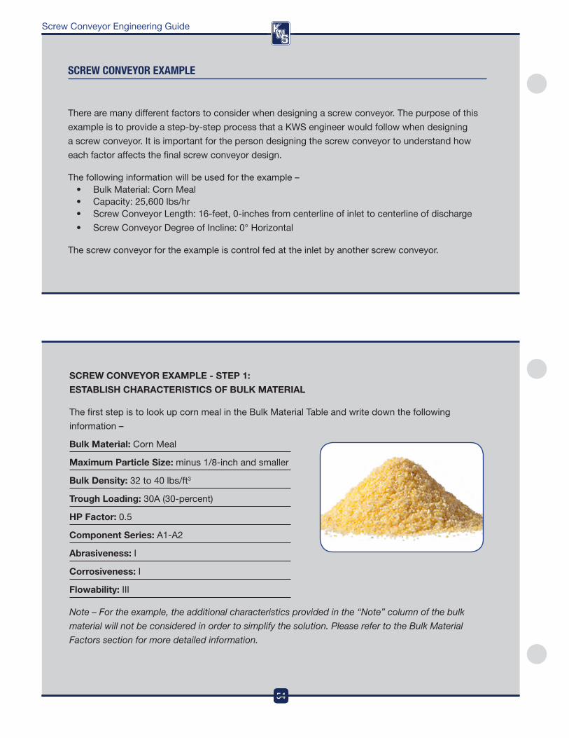
Bulk Material: Corn Meal
Maximum particle Size: minus 1/8-inch and smaller
Bulk Density: 32 to 40 lbs/ft3
Trough loading: 30a (30-percent)
Hp factor: 0 .5
Component Series: a1-a2
Abrasiveness: i
Corrosiveness: i
flowability: iii
Note – For the example, the additional characteristics provided in the “Note” column of the bulk
material will not be considered in order to simplify the solution. Please refer to the Bulk Material
Factors section for more detailed information.
54
DesignEngineeringManufacturing
55
DesignEngineeringManufacturing
Screw Conveyor Engineering Guide
sCReW COnVeYOR eXaMPle
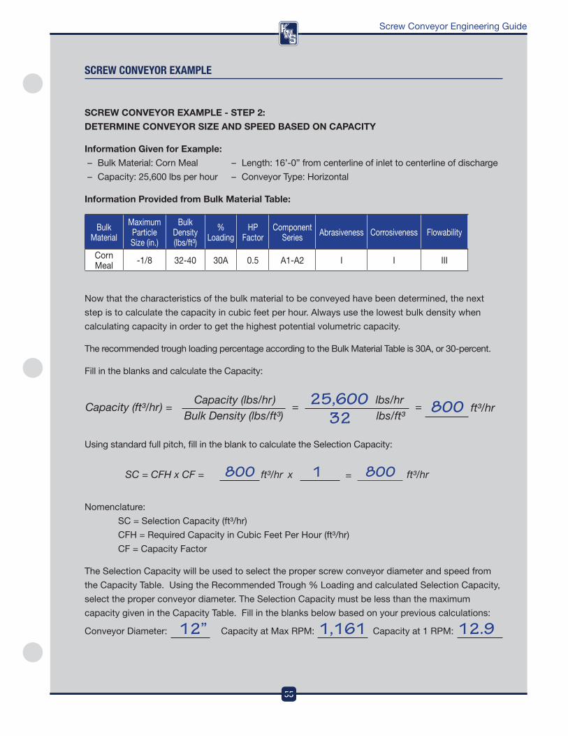
SCREW CoNVEYoR ExAMplE - STEp 2:
DETERMINE CoNVEYoR SIZE AND SpEED BASED oN CApACITY
Information Given for Example:
– Bulk Material: Corn Meal – Length: 16’-0” from centerline of inlet to centerline of discharge
– Capacity: 25,600 lbs per hour – Conveyor Type: Horizontal
Information provided from Bulk Material Table:
Bulk Material
Maximum particle Size (in .)
Bulk density (lbs/ft³)
% Loading
Hp factor
Component Series abrasiveness Corrosiveness flowability
Corn Meal -1/8 32-40 30a 0 .5 a1-a2 i i iii
now that the characteristics of the bulk material to be conveyed have been determined, the next
step is to calculate the capacity in cubic feet per hour . always use the lowest bulk density when
calculating capacity in order to get the highest potential volumetric capacity .
The recommended trough loading percentage according to the Bulk Material Table is 30a, or 30-percent .
fill in the blanks and calculate the Capacity:
11
Using standard full pitch, fill in the blank to calculate the Selection Capacity:
nomenclature:
SC = Selection Capacity (ft³/hr)
CfH = required Capacity in Cubic feet per Hour (ft³/hr)
Cf = Capacity factor
The Selection Capacity will be used to select the proper screw conveyor diameter and speed from
the Capacity Table . Using the recommended Trough % Loading and calculated Selection Capacity,
select the proper conveyor diameter . The Selection Capacity must be less than the maximum
capacity given in the Capacity Table . fill in the blanks below based on your previous calculations:
Conveyor diameter: Capacity at Max rpM: Capacity at 1 rpM: 12” 1,161 12.9
55
DesignEngineeringManufacturing
DesignEngineeringManufacturing
56
Screw Conveyor Engineering Guide
sCReW COnVeYOR eXaMPle
SCREW CoNVEYoR ExAMplE - STEp 3:
CAlCUlATE HoRSEpoWER REQUIREMENTS
Information Given for Example:
– Bulk Material: Corn Meal – Length (L): 16’-0” from centerline of inlet to centerline of discharge
– Capacity (Cp): 25,600 lbs/hr – Conveyor Type: Horizontal
Information provided from Bulk Material Table:
Bulk Material
Maximum particle Size (in .)
Bulk density (lbs/ft³)
% Loading
Hp factor
Component Series abrasiveness Corrosiveness flowability
Corn Meal -1/8 32-40 30a 0 .5 a1-a2 i i iii
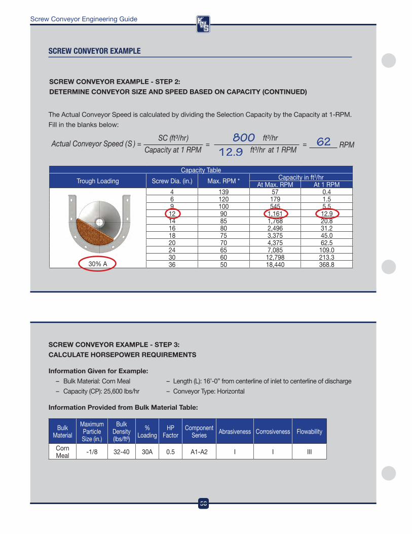
Capacity Table
Trough Loading Screw dia . (in .) Max . rpM * Capacity in ft3/hr at Max . rpM at 1 rpM
30% a
4 139 57 0 .46 120 179 1 .59 100 545 5 .5
12 90 1,161 12 .914 85 1,768 20 .816 80 2,496 31 .218 75 3,375 45 .020 70 4,375 62 .524 65 7,085 109 .030 60 12,798 213 .336 50 18,440 368 .8
The actual Conveyor Speed is calculated by dividing the Selection Capacity by the Capacity at 1-rpM .
fill in the blanks below:
SCREW CoNVEYoR ExAMplE - STEp 2:
DETERMINE CoNVEYoR SIZE AND SpEED BASED oN CApACITY (CoNTINUED)
56
DesignEngineeringManufacturing
57
DesignEngineeringManufacturing
Screw Conveyor Engineering Guide
sCReW COnVeYOR eXaMPle
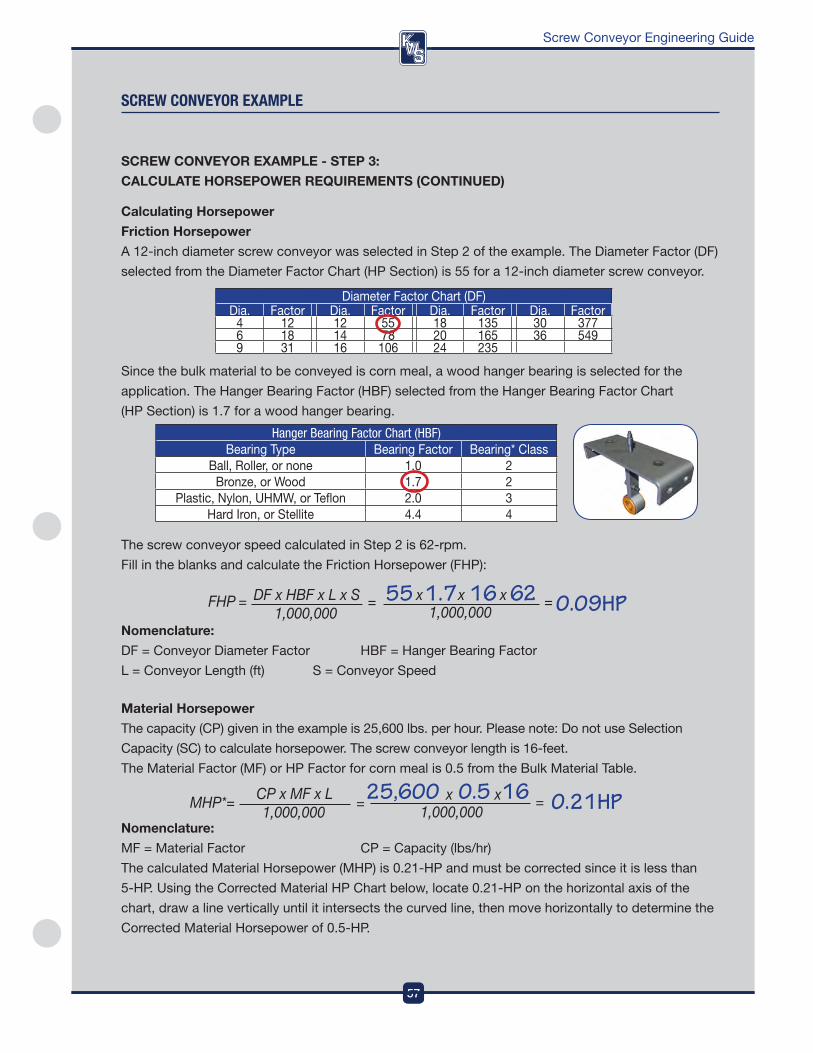
The screw conveyor speed calculated in Step 2 is 62-rpm .
fill in the blanks and calculate the friction Horsepower (fHp):
Nomenclature:
df = Conveyor diameter factor HBf = Hanger Bearing factor
L = Conveyor Length (ft) S = Conveyor Speed
Material Horsepower
The capacity (Cp) given in the example is 25,600 lbs . per hour . please note: do not use Selection
Capacity (SC) to calculate horsepower . The screw conveyor length is 16-feet .
The Material factor (Mf) or Hp factor for corn meal is 0 .5 from the Bulk Material Table .
Nomenclature:
Mf = Material factor Cp = Capacity (lbs/hr)
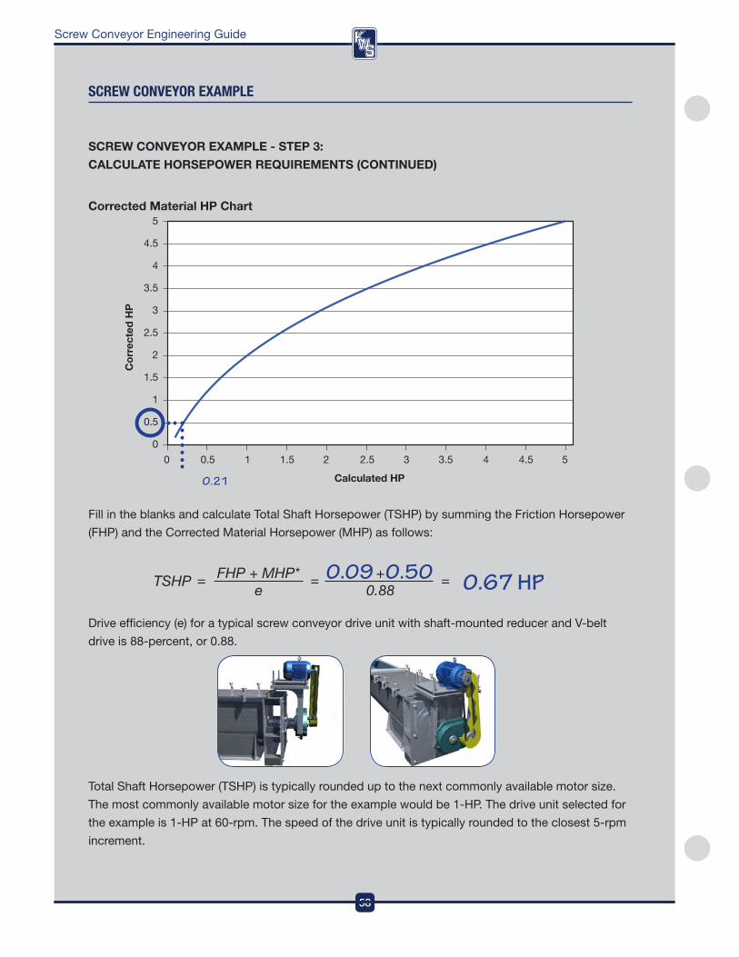
The calculated Material Horsepower (MHp) is 0 .21-Hp and must be corrected since it is less than
5-Hp . Using the Corrected Material Hp Chart below, locate 0 .21-Hp on the horizontal axis of the
chart, draw a line vertically until it intersects the curved line, then move horizontally to determine the
Corrected Material Horsepower of 0 .5-Hp .
SCREW CoNVEYoR ExAMplE - STEp 3:
CAlCUlATE HoRSEpoWER REQUIREMENTS (CoNTINUED)
diameter factor Chart (df)dia . factor dia . factor dia . factor dia . factor
4 12 12 55 18 135 30 3776 18 14 78 20 165 36 5499 31 16 106 24 235
Calculating Horsepower
friction Horsepower
a 12-inch diameter screw conveyor was selected in Step 2 of the example . The diameter factor (df)
selected from the diameter factor Chart (Hp Section) is 55 for a 12-inch diameter screw conveyor .
Since the bulk material to be conveyed is corn meal, a wood hanger bearing is selected for the
application . The Hanger Bearing factor (HBf) selected from the Hanger Bearing factor Chart
(Hp Section) is 1 .7 for a wood hanger bearing .
Hanger Bearing Factor Chart (HBF)Bearing Type Bearing factor Bearing* Class
Ball, roller, or none 1 .0 2Bronze, or wood 1 .7 2
plastic, nylon, UHMw, or Teflon 2 .0 3Hard iron, or Stellite 4 .4 4
57
DesignEngineeringManufacturing
DesignEngineeringManufacturing
58
Screw Conveyor Engineering Guide
fill in the blanks and calculate Total Shaft Horsepower (TSHp) by summing the friction Horsepower
(fHp) and the Corrected Material Horsepower (MHp) as follows:
drive efficiency (e) for a typical screw conveyor drive unit with shaft-mounted reducer and v-belt
drive is 88-percent, or 0 .88 .
Total Shaft Horsepower (TSHp) is typically rounded up to the next commonly available motor size .
The most commonly available motor size for the example would be 1-Hp . The drive unit selected for
the example is 1-Hp at 60-rpm . The speed of the drive unit is typically rounded to the closest 5-rpm
increment .
sCReW COnVeYOR eXaMPle
Calculated HP
0 0.5 1 1.5 2 2.5 3 3.5 4 4.5 5
Cor
rect
ed H
P
5
4.5
4
3.5
3
2.5
2
1.5
1
0.5
0
Corrected Material Hp Chart
0.21
SCREW CoNVEYoR ExAMplE - STEp 3:
CAlCUlATE HoRSEpoWER REQUIREMENTS (CoNTINUED)
58
DesignEngineeringManufacturing
59
DesignEngineeringManufacturing
Screw Conveyor Engineering Guide
59
DesignEngineeringManufacturing
SCREW CoNVEYoR ExAMplE - STEp 4:
CAlCUlATE ToRQUE REQUIREMENTS
Information Given for Example:
– Bulk Material: Corn Meal – Length: 16’-0” from centerline of inlet to centerline of discharge
– Capacity: 25,600 lbs/hr – Conveyor Type: Horizontal
Information provided from Bulk Material Table:
Bulk Material
Maximum particle Size (in .)
Bulk density (lbs/ft³)
% Loading
Hp factor
Component Series abrasiveness Corrosiveness flowability
Corn Meal -1/8 32-40 30a 0 .5 a1-a2 i i iii
Calculating full Motor Torque
a 1-Hp at 60-rpm drive unit was selected for the example screw conveyor . full Motor Torque is
calculated with the following equation below:
Hp = nameplate Horsepower of the motor on the screw conveyor
S = Screw Conveyor Speed .
The torque rating of the drive shaft, coupling shafts, coupling bolts and conveyor screw must be
greater than full Motor Torque for proper design .
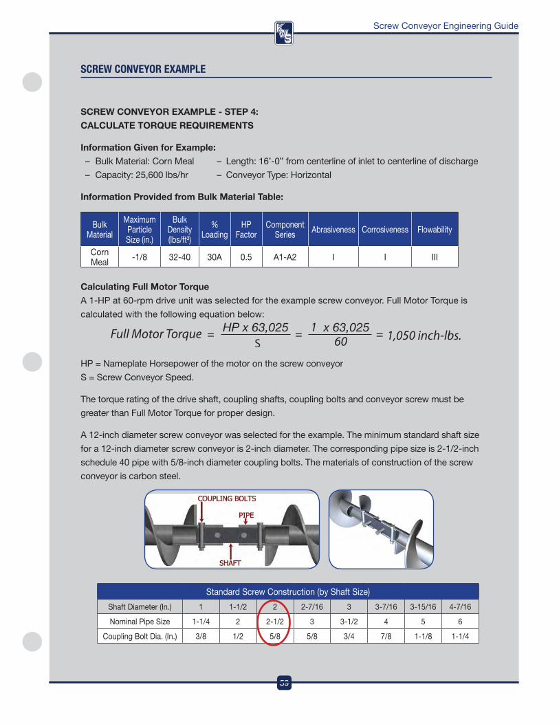
a 12-inch diameter screw conveyor was selected for the example . The minimum standard shaft size
for a 12-inch diameter screw conveyor is 2-inch diameter . The corresponding pipe size is 2-1/2-inch
schedule 40 pipe with 5/8-inch diameter coupling bolts . The materials of construction of the screw
conveyor is carbon steel .
Standard Screw Construction (by Shaft Size)
Shaft diameter (in .) 1 1-1/2 2 2-7/16 3 3-7/16 3-15/16 4-7/16
nominal pipe Size 1-1/4 2 2-1/2 3 3-1/2 4 5 6
Coupling Bolt dia . (in .) 3/8 1/2 5/8 5/8 3/4 7/8 1-1/8 1-1/4
sCReW COnVeYOR eXaMPle
DesignEngineeringManufacturing
60
Screw Conveyor Engineering Guide
SCREW CoNVEYoR ExAMplE - STEp 4:
CAlCUlATE ToRQUE REQUIREMENTS (CoNTINUED)
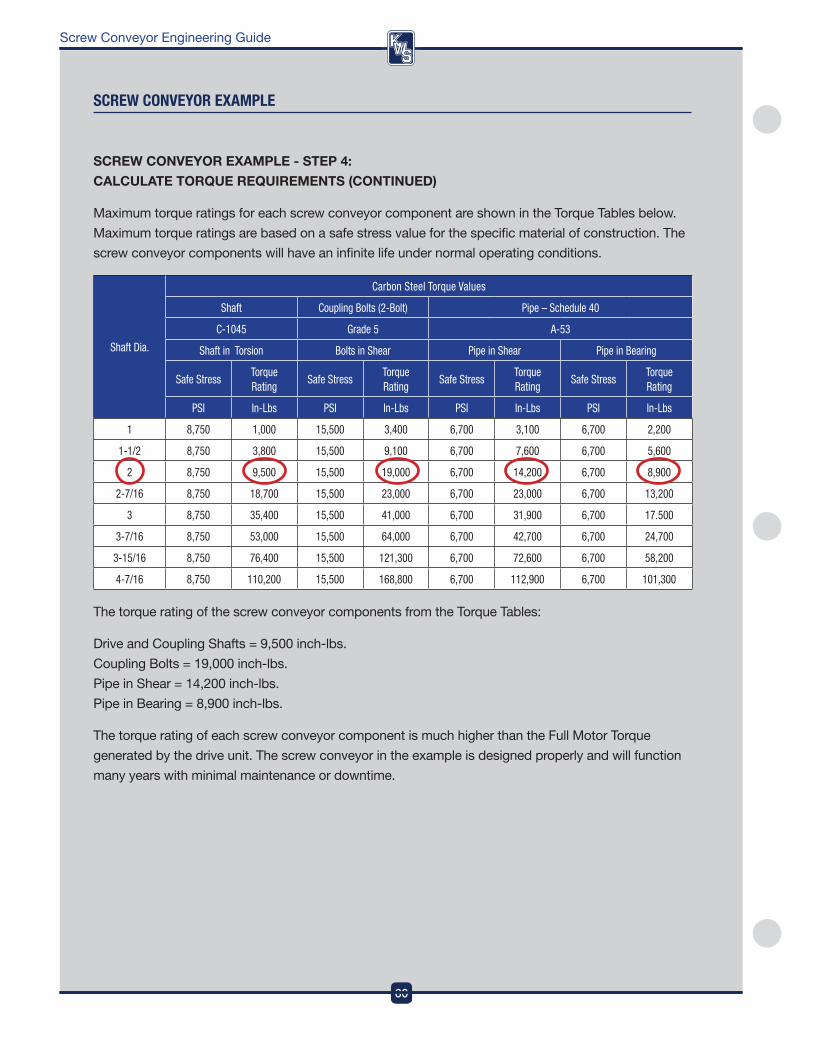
Maximum torque ratings for each screw conveyor component are shown in the Torque Tables below .
Maximum torque ratings are based on a safe stress value for the specific material of construction . The
screw conveyor components will have an infinite life under normal operating conditions .
Shaft Dia.
Carbon Steel Torque Values
Shaft Coupling Bolts (2-Bolt) Pipe – Schedule 40
C-1045 Grade 5 A-53
Shaft in Torsion Bolts in Shear Pipe in Shear Pipe in Bearing
Safe StressTorque Rating
Safe StressTorque Rating
Safe StressTorque Rating
Safe StressTorque Rating
PSI In-Lbs PSI In-Lbs PSI In-Lbs PSI In-Lbs
1 8,750 1,000 15,500 3,400 6,700 3,100 6,700 2,200
1-1/2 8,750 3,800 15,500 9,100 6,700 7,600 6,700 5,600
2 8,750 9,500 15,500 19,000 6,700 14,200 6,700 8,900
2-7/16 8,750 18,700 15,500 23,000 6,700 23,000 6,700 13,200
3 8,750 35,400 15,500 41,000 6,700 31,900 6,700 17.500
3-7/16 8,750 53,000 15,500 64,000 6,700 42,700 6,700 24,700
3-15/16 8,750 76,400 15,500 121,300 6,700 72,600 6,700 58,200
4-7/16 8,750 110,200 15,500 168,800 6,700 112,900 6,700 101,300
The torque rating of the screw conveyor components from the Torque Tables:
drive and Coupling Shafts = 9,500 inch-lbs .
Coupling Bolts = 19,000 inch-lbs .
pipe in Shear = 14,200 inch-lbs .
pipe in Bearing = 8,900 inch-lbs .
The torque rating of each screw conveyor component is much higher than the full Motor Torque
generated by the drive unit . The screw conveyor in the example is designed properly and will function
many years with minimal maintenance or downtime .
sCReW COnVeYOR eXaMPle
60
DesignEngineeringManufacturing
61
DesignEngineeringManufacturing
Screw Conveyor Engineering Guide
SCREW CoNVEYoR ExAMplE - STEp 5:
CoMpoNENT SERIES SElECTIoN
Information Given for Example:
– Bulk Material: Corn Meal – Length: 16’-0” from centerline of inlet to centerline of discharge
– Capacity: 25,600 lbs/hr – Conveyor Type: Horizontal
Information provided from Bulk Material Table:
Bulk Material
Maximum particle Size (in .)
Bulk density (lbs/ft³)
% Loading
Hp factor
Component Series abrasiveness Corrosiveness flowability
Corn Meal -1/8 32-40 30a 0 .5 a1-a2 i i iii
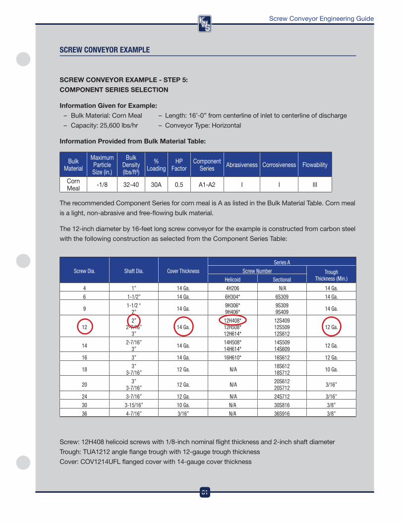
The recommended Component Series for corn meal is a as listed in the Bulk Material Table . Corn meal
is a light, non-abrasive and free-flowing bulk material .
The 12-inch diameter by 16-feet long screw conveyor for the example is constructed from carbon steel
with the following construction as selected from the Component Series Table:
sCReW COnVeYOR eXaMPle
Screw Dia. Shaft Dia. Cover Thickness
Series A
Screw Number Trough Thickness (Min.)Helicoid Sectional
4 1” 14 Ga. 4H206 N/A 14 Ga.
6 1-1/2” 14 Ga. 6H304* 6S309 14 Ga.
9 1-1/2 “ 2” 14 Ga. 9H306*
9H406*9S309 9S409 14 Ga.
122”
2-7/16” 3”
14 Ga.12H408* 12H508* 12H614*
12S409 12S509 12S612
12 Ga.
14 2-7/16” 3” 14 Ga. 14H508*
14H614*14S509 14S609 12 Ga.
16 3” 14 Ga. 16H610* 16S612 12 Ga.
18 3” 3-7/16” 12 Ga. N/A 18S612
18S712 10 Ga.
20 3” 3-7/16” 12 Ga. N/A 20S612
20S712 3/16”
24 3-7/16” 12 Ga. N/A 24S712 3/16”
30 3-15/16” 10 Ga. N/A 30S816 3/8”
36 4-7/16” 3/16” N/A 36S916 3/8”
Screw: 12H408 helicoid screws with 1/8-inch nominal flight thickness and 2-inch shaft diameter
Trough: TUa1212 angle flange trough with 12-gauge trough thickness
Cover: Cov1214UfL flanged cover with 14-gauge cover thickness
61
DesignEngineeringManufacturing
DesignEngineeringManufacturing
62
Screw Conveyor Engineering Guide
62
DesignEngineeringManufacturing
sCReW COnVeYOR eXaMPle
SCREW CoNVEYoR ExAMplE - STEp 5:
CoMpoNENT SERIES SElECTIoN (CoNTINUED)
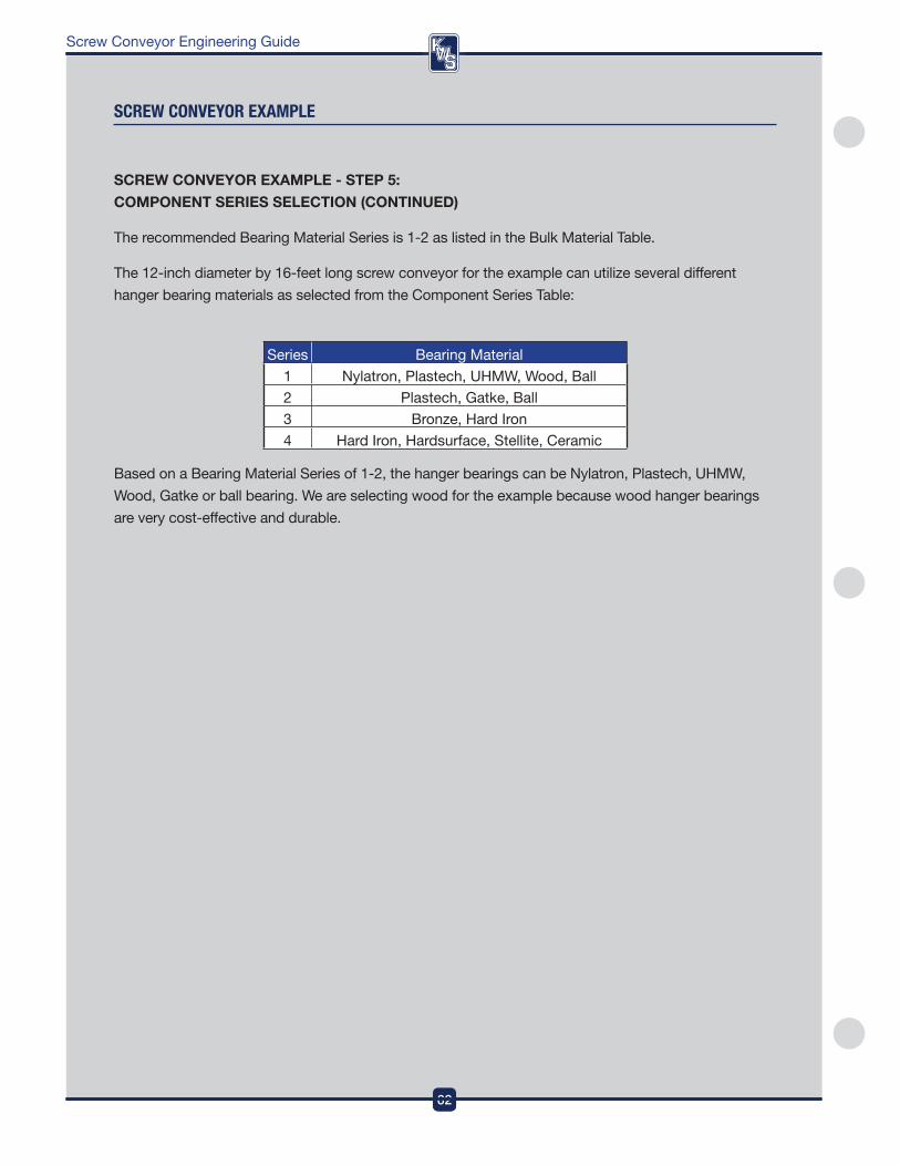
The recommended Bearing Material Series is 1-2 as listed in the Bulk Material Table .
The 12-inch diameter by 16-feet long screw conveyor for the example can utilize several different
hanger bearing materials as selected from the Component Series Table:
Series Bearing Material
1 nylatron, plastech, UHMw, wood, Ball
2 plastech, Gatke, Ball
3 Bronze, Hard iron
4 Hard iron, Hardsurface, Stellite, Ceramic
Based on a Bearing Material Series of 1-2, the hanger bearings can be nylatron, plastech, UHMw,
wood, Gatke or ball bearing . we are selecting wood for the example because wood hanger bearings
are very cost-effective and durable .
63
DesignEngineeringManufacturing
Screw Conveyor Engineering Guide
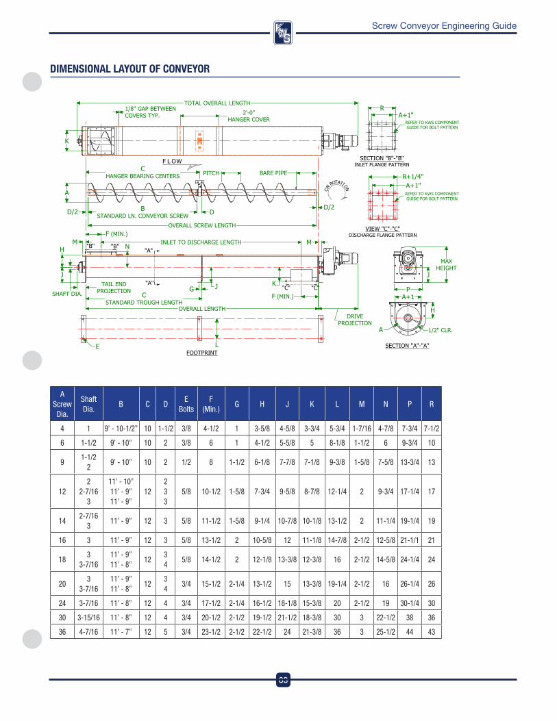
DIMensIOnal laYOUT Of COnVeYOR
A Screw Dia.
Shaft Dia.
B C DE
BoltsF
(Min.)G H J K L M N P R
4 1 9’ - 10-1/2” 10 1-1/2 3/8 4-1/2 1 3-5/8 4-5/8 3-3/4 5-3/4 1-7/16 4-7/8 7-3/4 7-1/2
6 1-1/2 9’ - 10” 10 2 3/8 6 1 4-1/2 5-5/8 5 8-1/8 1-1/2 6 9-3/4 10
91-1/2
29’ - 10” 10 2 1/2 8 1-1/2 6-1/8 7-7/8 7-1/8 9-3/8 1-5/8 7-5/8 13-3/4 13
122
2-7/16 3
11’ - 10” 11’ - 9” 11’ - 9”
122 3 3
5/8 10-1/2 1-5/8 7-3/4 9-5/8 8-7/8 12-1/4 2 9-3/4 17-1/4 17
142-7/16
311’ - 9” 12 3 5/8 11-1/2 1-5/8 9-1/4 10-7/8 10-1/8 13-1/2 2 11-1/4 19-1/4 19
16 3 11’ - 9” 12 3 5/8 13-1/2 2 10-5/8 12 11-1/8 14-7/8 2-1/2 12-5/8 21-1/1 21
183
3-7/1611’ - 9” 11’ - 8”
123 4
5/8 14-1/2 2 12-1/8 13-3/8 12-3/8 16 2-1/2 14-5/8 24-1/4 24
203
3-7/1611’ - 9” 11’ - 8”
123 4
3/4 15-1/2 2-1/4 13-1/2 15 13-3/8 19-1/4 2-1/2 16 26-1/4 26
24 3-7/16 11’ - 8” 12 4 3/4 17-1/2 2-1/4 16-1/2 18-1/8 15-3/8 20 2-1/2 19 30-1/4 30
30 3-15/16 11’ - 8” 12 4 3/4 20-1/2 2-1/2 19-1/2 21-1/2 18-3/8 30 3 22-1/2 38 36
36 4-7/16 11’ - 7” 12 5 3/4 23-1/2 2-1/2 22-1/2 24 21-3/8 36 3 25-1/2 44 43

DesignEngineeringManufacturing
64
Screw Conveyor Engineering Guide
Notes

65
DesignEngineeringManufacturing
Screw Conveyor Engineering Guide
Notes
DesignEngineeringManufacturing
3041 Conveyor Drive | Burleson, TX 76028Toll-free: (800) 543-6558 | Local Phone: (817) 295-2240 | Fax: (817) 447-8528
Inquiries: [email protected] | www.kwsmfg.com
MADE IN THE USA
ISO 9001Certified
Conveying Knowledge, Workmanship, Solutions
What makes KWS different from other manufacturers?At KWS we understand the needs and exceed the expectations of our Customers. As an ISO-9001 certified company, quality is integrated into every aspect of our processes. Quality is defined by the Customer, and derived from the total KWS Customer experience. It’s not just product quality, but quality throughout every step of the Sales, Engineering and Manufacturing processes. Quality starts with our first Customer contact and never ends.
© Copyright 2015, KWS Manufacturing, Ltd. 100115
Related Documents


