Scott Hayden, Team Lead – Chief Engineer, Performance & Structures Specialist Dana Pugh – Trade Studies and Propulsion Specialist Dany Fahmy – 3-D designer, Aerodynamicist Court Groves – Stability and Control Specialist Morphing Aircraft Design MAE 155B, Aerospace Engineering Design II University of California, San Diego Jacobs School of Engineering June 7, 2004 Charles Chase, Lockheed Martin Dr. James Lang, Project Advisor

Scott Hayden, Team Lead – Chief Engineer, Performance & Structures Specialist Dana Pugh – Trade Studies and Propulsion Specialist Dany Fahmy – 3-D designer,
Dec 22, 2015
Welcome message from author
This document is posted to help you gain knowledge. Please leave a comment to let me know what you think about it! Share it to your friends and learn new things together.
Transcript

Scott Hayden, Team Lead – Chief Engineer, Performance & Structures Specialist
Dana Pugh – Trade Studies and Propulsion Specialist
Dany Fahmy – 3-D designer, Aerodynamicist
Court Groves – Stability and Control Specialist
Morphing Aircraft Design
MAE 155B, Aerospace Engineering Design II
University of California, San DiegoJacobs School of Engineering
June 7, 2004Charles Chase, Lockheed MartinDr. James Lang, Project Advisor

Goals, Schedule and Project Cost Design Drivers
Initial Morphing Aircraft Concepts Delta Wing Jive Straight Jacket
Final Design Concept Straight Jacket Method of Morphing
System Design Configuration Aerodynamics Propulsion Stability and Control Materials and Structures Performance Trade Studies Cost Estimates
Conclusions References and Acknowledgments
Morphing Aircraft Project Outline

Goals, Schedule and Project Cost
Project Description
Design a Strike Aircraft with morphing capabilities Maximize the Strike Mission performance. Ingress and Egress demand supersonic cruising at Mach 2 Carry a 2,000 pound internal weapons payload
Three morphing variations to maximize flight performance and Minimize project costs:
“Swing" wing concept Fan wing concept Switchblade wing concept
Trade studies varying T/W, W/S, and Aspect Ratio up to 20%
Perform preliminary design analysis on final aircraft choice
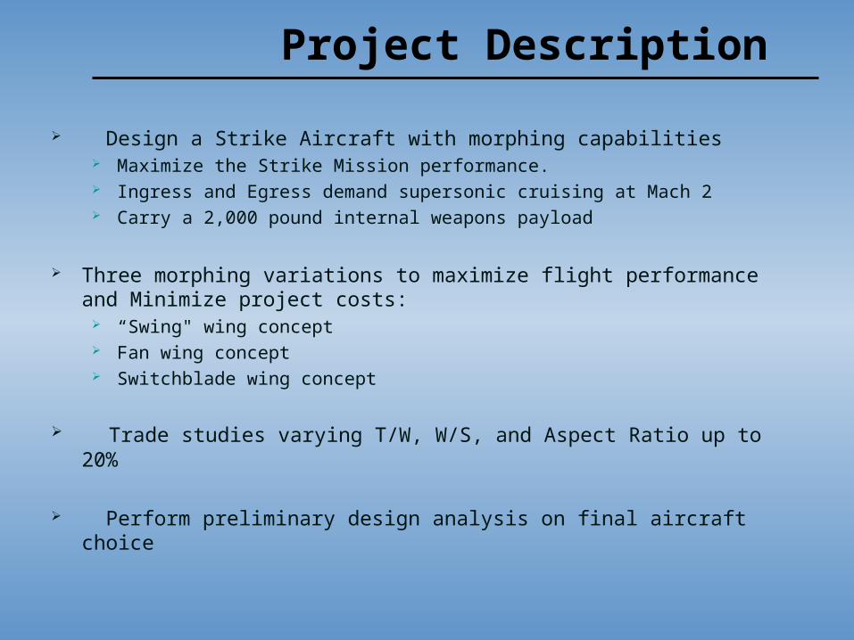
Climb from Sea Level to Best Cruise Altitude ( ≥ 55,000 feet )
Ingress for 1,200 nautical miles at Mach 2.0 and BCA
“Strike Patrol” for 4 hours at subsonic velocity ( ≥ 55,000 feet )
Return to base at Mach 2.0 and BCA
Carry Reserve fuel for additional 20 minute loiter
Descend to Sea Level and Land
SUBsonic Configuration: Make TEN sustained 360° turns at M=0.7 Withstand a 3g sustained load ( ≥ 55,000 feet )
SUPERsonic Configuration: Make ONE sustained 180° turn at M=2.0
Mission Requirements
Design Drivers
Supercruise at Mach 2
Aerodynamics Wave Drag Area-Ruling
Stability and Control Yaw and Pitch Stability are critical
Propulsion Utilize only military thrust to reach and maintain cruise velocity of Mach
2

Design Drivers (cont…)
Subsonic to Supersonic and vice versa
Maximize performance for BOTH supersonic cruise and subsonic loiter
Feasibly morph between optimal operating configurations
Recognize this HUGE change Aerodynamics Stability and Control Systems Optimize!
0 1
2 3
4 5
6 7
8
9 10
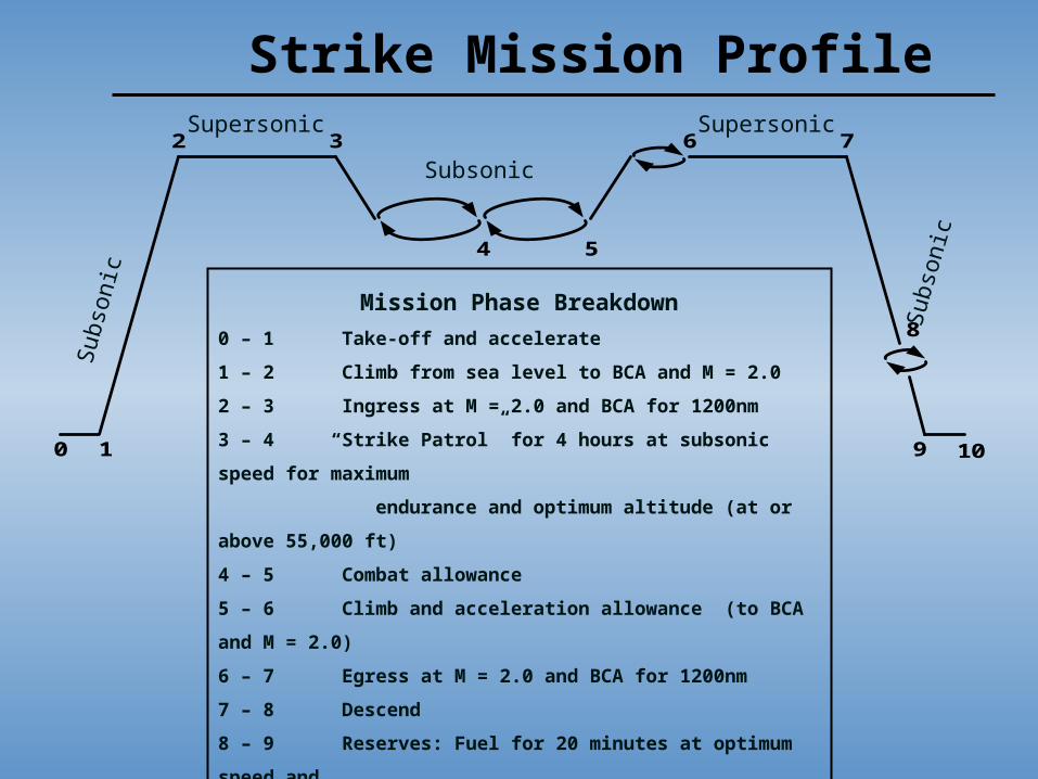
Mission Phase Breakdown
0 – 1 Take-off and accelerate
1 – 2 Climb from sea level to BCA and M = 2.0
2 – 3 Ingress at M = 2.0 and BCA for 1200nm
3 – 4 “Strike Patrol” for 4 hours at subsonic speed for maximum
endurance and optimum altitude (at or above 55,000 ft)
4 – 5 Combat allowance
5 – 6 Climb and acceleration allowance (to BCA and M = 2.0)
6 – 7 Egress at M = 2.0 and BCA for 1200nm
7 – 8 Descend
8 – 9 Reserves: Fuel for 20 minutes at optimum speed and
altitude for maximum endurance
9 - 10 Landing
Strike Mission ProfileSubso
nic
Subso
nic
Subsonic
Supersonic Supersonic

Spring BreakMilestones
Final Schedule
Final Presentation
Preliminary Design
Switchblade concept
Fan concept
Swing wing design
Trade Studies
Conceptual Design
Objectives and Success Criteria
June 7th
10987654321
Weeks During Spring Quarter 2004 (March 22 – June 7)

Project Costs
Engineering (4 engineers, $92/hour, 12 hours/week, 11 weeks): $48,576
Travel to Lockheed Martin Sponsor (food/gas): $95
Miscellaneous Design Tools: $150
Total - Pay up!
Design Project Cost Estimates
Initial Morphing Aircraft Concepts

Conceptual Design Approach
Individually design three different morphing aircraft Each satisfying the mission requirements Highlight design drivers – Supercruise at M=2, Morph to optimize
performance
Develop method to compare each individual design Fair Systematic Same set of assumptions and design restrictions
Use subjective and objective comparisons to downsize to a final design
Measures of Merit Weight! Pugh Chart

Conceptual Design Approach (cont…)
Subsonic Wing ParametersAspect Ratio
Leading Edge SweepTaper RatioSwet/Sref
Supersonic Wing ParametersAspect Ratio
Leading Edge SweepTaper RatioSwet/Sref
T/Wtakeoff(initial guess)
Now Back trackwith W/Stakeoff
W/Si
takeoff
landing
manuever
Gives Max.Demanded Wing
Loading
CommonAssumptions:
MmaxAltitudeTSFCCD0K
L/Di
WeightFractions
Calculate SubsonicLoiter Velocity
Size Wings
Refine W/S, T/Wi andAssumptions to
maximize performace
Reiterate!

Delta Wing
SupersonicSubsonic

Delta Wing
TOGW: 90000lbs. Wf=46967lbs We=41287lbs
Subsonic / supersonic aspect ratio: 8 / 2.91
Cdosubsonic / supersonic: .0105 / .01575
Span subsonic / supersonic: 164.75 / 52.16ft
L/D loiter / supercruise: 16.778 / 7.906
W/S loiter / supercruise: 27.38 / 89.29
T/W loiter / supercruise: 0.385 / 0.377

JiveSupersonic Subsoni
c
Inlets
Pivot Points
2 Engines
1 1 VerticVertical Tailal Tail
Rotates Inside Fuselage

Swings in from a pivot point
The swing motion follows a designed track within the fuselage
From subsonic configuration to supersonic configuration, only about 70% of the wing swings in
Latches into supersonic configuration with clamps creating a smaller aspect ratio
Jive - How it Morphs

JiveWeight SummaryTOGW (lb) 180000
We (lb) 81362
Wf uel (lb) 99360
W/Stakeof f (lb) 47.3
T/Wtakeof f (lb) 0.235
We/W0 0.452
Wf /W0 0.55
Vehicle CharacteristicsSubsonicWingspan (ft) 154.8Aspect Ratio 6.3Cdo (M=0.70) 0.015K (M=0.70) 0.080(L/D)max subsonic 14.1
SupersonicWingspan (ft) 50.1Aspect Ratio 2.4Cdo (M=2.0) 0.023K (M=2.0) 0.377(L/D)max supersonic 7.8
Jive – Weight & Characteristics

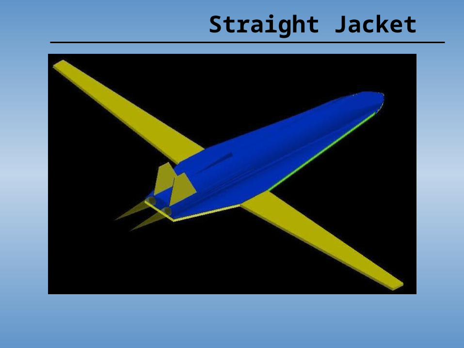
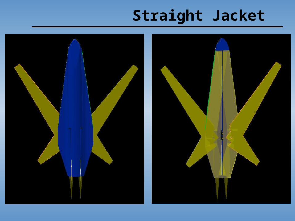
Straight Jacket
High Aspect Ratio Subsonic Wings Maximize L/D for loiter
Low Aspect Ratio Supersonic Wings Reduce Drag Maximize Range Increase Maneuverability
Combine wings to simplify Morph Reduce mechanical/electrical/control costs and complications Utilize long slender subsonic wings to shape slender body Achieve something never seen before
Aim of Design

Straight Jacket - Subsonic

Straight Jacket - Supersonic

Straight Jacket – Method of Morphing

Comparison
Delta Wing Straight Jacket JivePossibility ++ + +
Probability + O +
Risk OAerodynamics (super) ++ ++ OAerodynamics (sub) + +
Morphing Capabilities O + +
Aesthetic Appeal O + OOverall O + +
Team INFERNO Pugh Chart
POOR MODERATELY POORO NEUTRAL+ GOOD
++ EXCELLENT
LEGEND
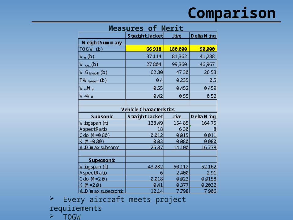
ComparisonMeasures of Merit
Every aircraft meets project requirements TOGW
Straight Jacket Jive Delta WingWeight Summary
TOGW (lb) 66,918 180,000 90,000
We (lb) 37,114 81,362 41,288
Wfuel (lb) 27,804 99,360 46,967
W/Stakeoff (lb) 62.80 47.30 26.53
T/Wtakeoff (lb) 0.4 0.235 0.5
We/W0 0.55 0.452 0.459
Wf/W0 0.42 0.55 0.52
Subsonic Straight Jacket Jive Delta WingWingspan (ft) 138.49 154.85 164.75Aspect Ratio 18 6.30 8Cdo (M=0.80) 0.012 0.015 0.011K (M=0.80) 0.03 0.080 0.080(L/D)max subsonic 25.87 14.100 16.778
SupersonicWingspan (ft) 43.282 50.112 52.162Aspect Ratio 6 2.400 2.91Cdo (M=2.0) 0.018 0.023 0.0158K (M=2.0) 0.41 0.377 0.2032(L/D)max supersonic 12.14 7.798 7.906
Vehicle Characteristics

Final Design Concept
and the winner is…

STRAIGHT JACKET

Straight Jacket
Straight Jacket
Straight Jacket
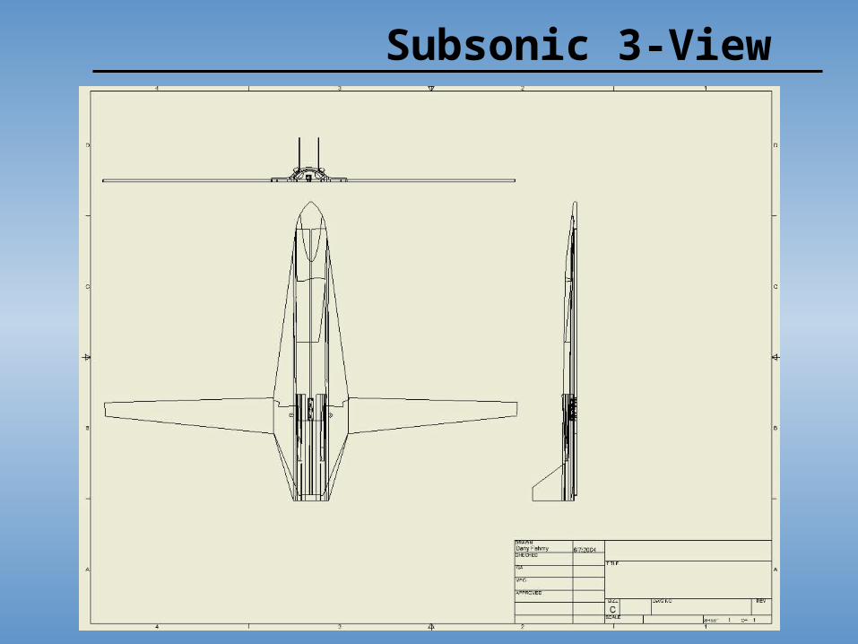
Subsonic 3-View
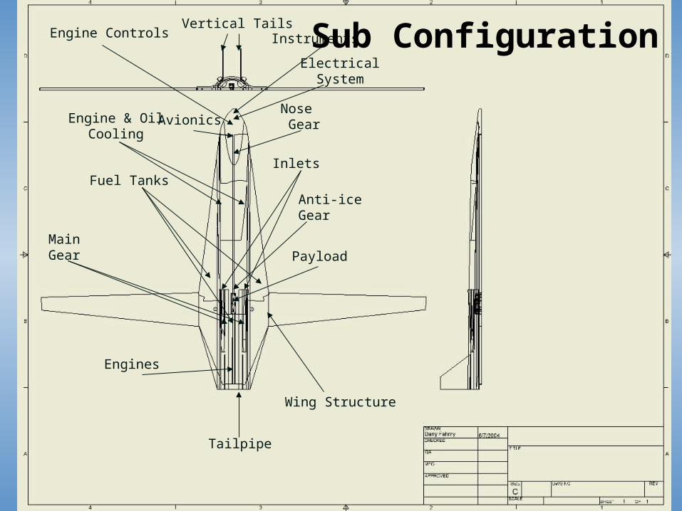
Vertical Tails
Payload
Engines
Wing Structure
Inlets
Nose Gear
Main Gear
Fuel Tanks
ElectricalSystem
Tailpipe
Engine & OilCooling
InstrumentsEngine Controls
Anti-iceGear
Avionics
Sub Configuration

Supersonic 3-View

Method of MorphingConcept:
Wing design incorporating single subsonic and supersonic wing into ONE structure
Takeoff and climb to BCA in subsonic formation
Morph to Supersonic formation for Mach 2 ingress
Accelerate in subsonic formation to M=0.7 Cervos/mechanisms “pop” wings down Large gears simultaneously rotate wings forward Mach 0.7 Mach 1
Use advanced controls systems Utilize seamless elevons and ailerons on BOTH wings Create lift and stability
Cervos/mechanisms bring wings back into fuselage and secure into place
And away we go… accelerate to M=2

Method of Morphing
Cross Section of Fuselage in Supersonic Formation
Reach Strike destination and slow to Mach 1
Cervos/mechanisms “pop” down wings Slowly draw subsonic wings from forward fuselage
Allow aerodynamic forces to deploy wings Only apply resistive force with gears

Method of Morphing
Front view of Straight Jacket in Subsonic Formation
Reduce lift and drag on forked wings Use seamless elevons and ailerons to minimize lift drag Advanced feedback control systems Allow drag forces to pull back wings
Natural Aerodynamic forces will slow aircraft from M=1 to M=0.7
Wings rotate out
Cervos/mechanisms bring wings back into fuselage and secure into place
Survey and drop payload if necessary… Morph back and RTB

Method of MorphingTop View of Wing Planform
Bottom View of Wing Planform
Back View of Wing Planform
Master Morph Control Gear
Simultaneously controlled wing gears
Subsonic Wings
Supersonic Wing
Large Steel / Titanium Strut
Re-lubricating Bearings
Titanium Circular Shafts
Bottom Shaft Brace

Method of Morphing
Use tooth to stabilize hidden wings Bring wings up and down Controlled by same servos and mechanisms, simultaneously Used to catch wings bring brought in Helps guide back into fuselage pocket
Hidden Wing Support – The Tooth
Tooth

Method of Morphing
New Belly material (IN RED)
“Smart” material - Polymer that forms to wings and tooth when collapsed
Stiffens and reduces surface area when wings are out Able to take Mach 2 airload from skin friction drag
Drag Reduction Technology
System Design

Aerodynamic CharacteristicsSubsonic Supersonic
Aspect Ratio 14 6
Airfoil NACA 4412 NACA 64-206
t/c .12 .06
Wing Span 168.46 59.78
Wing Area 2027.09 595.54
Sweep 8 28
Cl max 1.4 .0091
(L/D)max 24.56 10.75
Cdo .012 .036
Oswald efficiency 0.66 0.87
Swet/Sref 4 10
Taper Ratio 0.35 0.25
Aerodynamics

TOGW = 83,939 Lbs
We = 49,063 Lbs
Wf = 34,876 Lbs
Wf/W = 0.43
W/Sto = 39.49 Lb/ft2
T/Wto = 0.4
Fuel burn by mission segment (lb)
1) take off / acceleration 802.5
2) Climb 5005.2
3) Ingress 7275.1
4) Strike Patrol 8050.4
5) Combat allowance 1043.8
6) Accel/Climb Allowance 2990.0
7) Egress 6783.6
8) Descend 241.5
9) Reserves 567.1
10) Land 142.5
Weight Summary – Strike Mission

Cdo vs Mach Number
0
0.005
0.01
0.015
0.02
0.025
0.03
0.035
0.04
0 0.5 1 1.5 2 2.5
Mach Number
Cd
o Series1
CDO vs Mach Number

K vs Mach Number
0
0.05
0.1
0.15
0.2
0.25
0.3
0 0.5 1 1.5 2 2.5
Mach Number
K Series1
K vs Mach Number
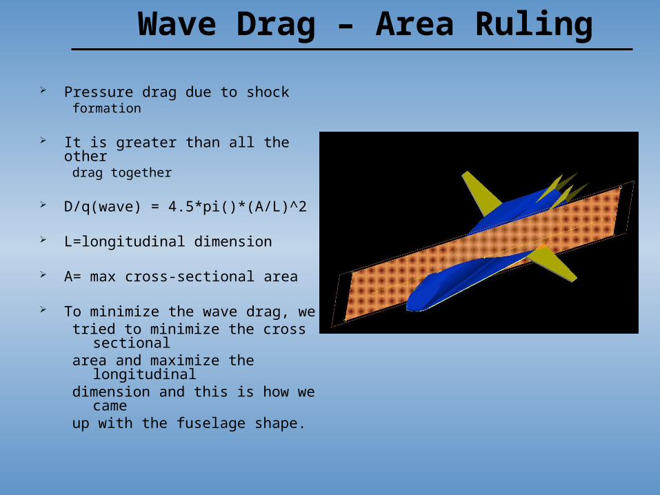
Pressure drag due to shockformation
It is greater than all the otherdrag together
D/q(wave) = 4.5*pi()*(A/L)^2
L=longitudinal dimension
A= max cross-sectional area
To minimize the wave drag, wetried to minimize the cross
sectionalarea and maximize the
longitudinaldimension and this is how we
cameup with the fuselage shape.
Wave Drag – Area Ruling
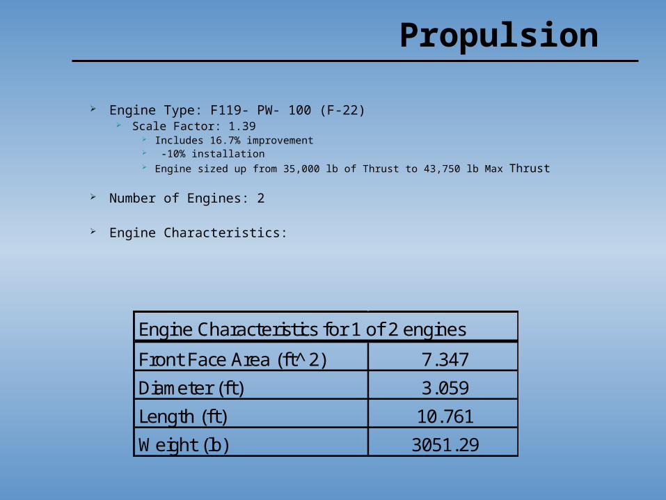
Engine Type: F119- PW- 100 (F-22) Scale Factor: 1.39
Includes 16.7% improvement -10% installation Engine sized up from 35,000 lb of Thrust to 43,750 lb Max Thrust
Number of Engines: 2
Engine Characteristics:
Engine Characteristics for 1 of 2 engines
Front Face Area (ft 2̂) 7.347
Diameter (ft) 3.059
Length (ft) 10.761
Weight (lb) 3051.29
Propulsion

Propulsion – F119
2 Engine Performance Thrust
Sea-Level Static Max Thrust (lbs) 43750
Supercruise (M=2) Thrust @ BCA (lbs) 5051

Inlet and Duct Design
Variable Inlet Design
Inlet Location
Duct Location and Inlet Location

Inlet
Inlet in front of the Leading edge

Nozzle
Ejector design cools the afterburner and nozzle
The converging-diverging design allows easier transitions between subsonic and supersonic
Nozzle Length ~ 2.5 feet
Afterburner & Nozzle ~ 6.3 feet

Nozzle Design Alternative
A component of the F119
Vectoring flaps are the most common vectoring-nozzle type
Need to do Trade Studies of cost and surface sizing to see if beneficial
2D Thrust Vectoring

Propulsion – Capture Area
Capture Area Versus Supercruise Mach Numbers for BCA
0
5
10
15
20
25
30
0 0.5 1 1.5 2 2.5
Mach Number
Acap
ture
(ft
)

TSFC VS. M and Altitude for Military Thrust for F119
TSFC for Miltary Power Versus Mach Number and Altitude
0.80
1.00
1.20
1.40
1.60
1.80
2.00
2.20
2.40
2.60
2.80
0 0.5 1 1.5 2 2.5
Mach Number
TS
FC
(1/
hr)
0 ft
5k ft
10k ft
15k ft
20k ft
25k ft
30k ft
35k ft
> 35k ft

Trade Studies
Total Weight Versus Aspect Ratio for Supersonic and Subsonic Configurations
0
50000
100000
150000
200000
250000
300000
0 5 10 15 20 25
Aspect Ratio
Wo (
lbs)
AR(sub) = 15
AR(sub) = 16
AR(sub) = 17
AR(sub) = 18
AR(sub) = 19
AR(sub) = 20
AR (sup) = 2
AR (sup) = 3
AR (sup) = 4
AR (sup) = 5
AR (sup) = 6
AR (sup) = 7
AR (sup) = 8
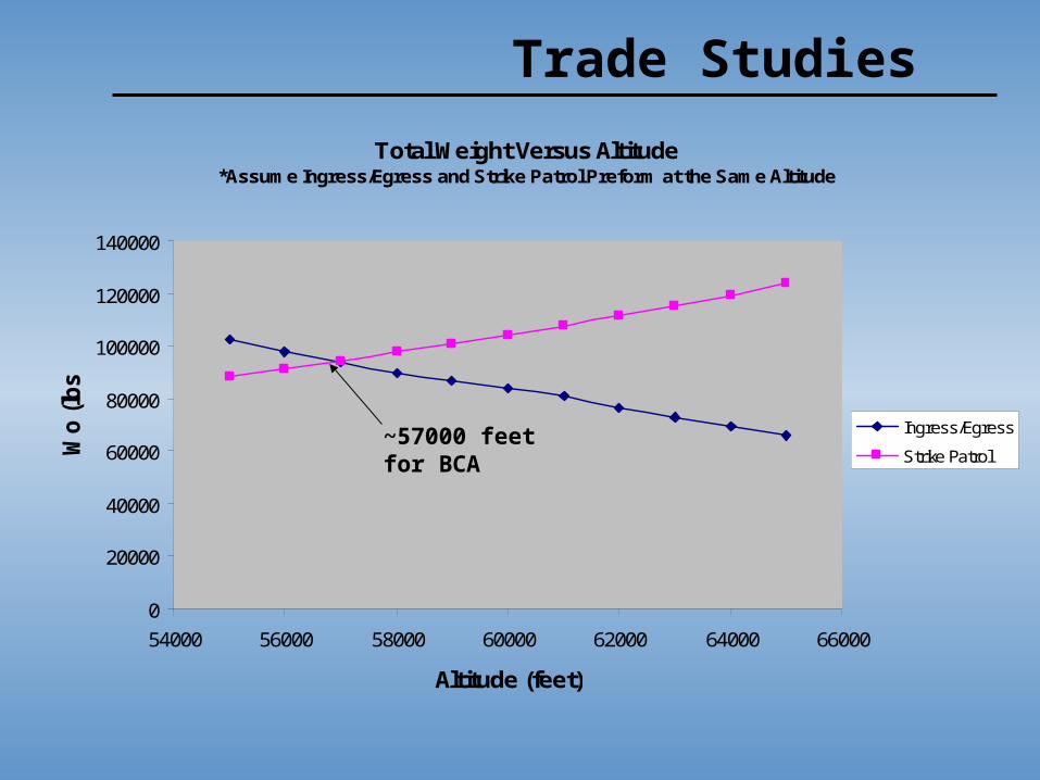
Total Weight Versus Altitude*Assume Ingress/Egress and Strike Patrol Preform at the Same Altitude
0
20000
40000
60000
80000
100000
120000
140000
54000 56000 58000 60000 62000 64000 66000
Altitude (feet)
Wo
(lb
s)
Ingress/Egress
Strike Patrol
Trade Studies
~57000 feet for BCA

Trade Studies
Total Weight Versus Take Off Thrust-to-Weight Ratio for Varying Ingress Wing Loading
0
100000
200000
300000
400000
500000
600000
700000
800000
900000
1000000
0 0.2 0.4 0.6 0.8 1 1.2
T/Wtakeoff
Wo
(lb
s)
W/Singress=70
W/Singress=80
W/Singress=90
W/Singress=100
W/Singress=110
W/Singress=120
W/Singress=130
W/Singress=140
W/Singress=150

Stability and Control
The Basics 4 control surfaces Elevons, Ailerons, RudderAilerons – 2 configurations
Subsonic & Supersonic Elevons – Only on subsonic
configuration Designed for increased stability at
loiter speed Rudder – Vertical twin tails
rudders sized to allow for stability at M=2+
Leading edge flaps Used to alter camber and
decrease lift during morphing phase

Stability and Control
Subsonic Supersonic

Stability and Control
Advanced controls Fluidic thrust vectoring
Increased maneuverability and performance at high supersonic Advantages Disadvantages
Fly by wire controls Automatic cg maintenance
Using sensors and fuel pumps

Stability and Control Maintenance of center of gravity
Phases: 1. subsonic cg 2. supersonic cg 3. subsonic post-payload drop 4. supersonic cg post-payload drop
Travel of center of gravity
81.281.3
81.481.581.6
81.781.881.9
82
82.182.2
1 2 3 4
Morphing Phase (1=subsonic; 2=supersonic; 3=subsonic post payload drop; 4=supersonic post
payload drop)
loca
tio
n o
f cg
fro
m n
ose
of
airc
raft
Series1

Stability and Control

Detailed Weight analysis Wing weight: 15527.02 lbs
Subsonic wing: 10431.51 lbs Supersonic wing: 5994.72 lbs
Fuselage weight: 8983.85 lbs
Installed engine weight: 8404.29 lbs
Vertical tail weight: 7686.02
Fuel system weight (empty): 2026.31
Payload: 2000 lbs
Avionics weight: 1332.66 lbs
Final component build up weight (empty): 50553.1 lbs With fuel: 85356.9 lbs

Landing Gear Main Landing Gear
Max static load: 81866.38 lbs Extended length: 60 in.
Nose Landing Gear Min static load: 490.52 lbs Max static load: 10,659.19 lbs Dynamic breaking load: 2461.49 Extended length: 72 in.
Kinetic Energy absorbed by breaking: 6.85x10^6 ft-lbs
Vertical Kinetic Energy absorbed by deflecting shock and tire: 223,995.6 ft-lbs
Materials and Structures
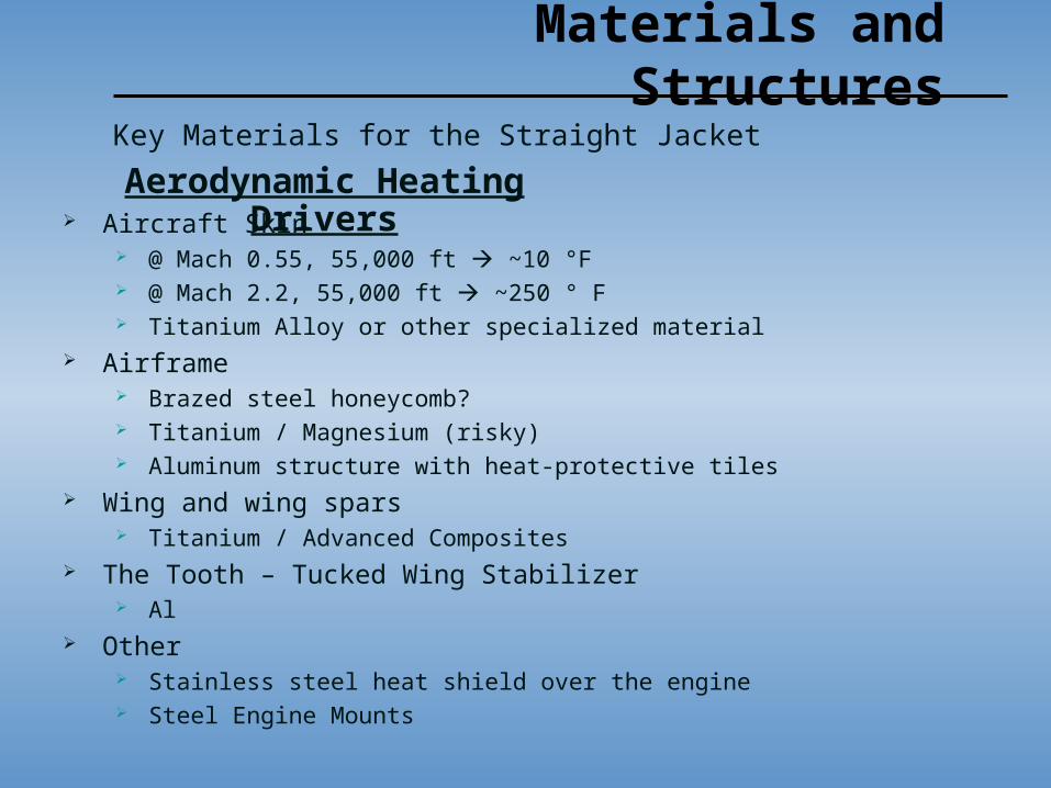
Aircraft Skin @ Mach 0.55, 55,000 ft ~10 °F @ Mach 2.2, 55,000 ft ~250 ° F Titanium Alloy or other specialized material
Airframe Brazed steel honeycomb? Titanium / Magnesium (risky) Aluminum structure with heat-protective tiles
Wing and wing spars Titanium / Advanced Composites
The Tooth – Tucked Wing Stabilizer Al
Other Stainless steel heat shield over the engine Steel Engine Mounts
Key Materials for the Straight Jacket
Aerodynamic Heating Drivers

Materials and Structures
Belly Skin New Age material “Smart” Materials Micro Piezoelectric actuators Must change and sustain aerodynamic drag load
Elevons and Ailerons Seamless “smart” material
Key Materials for the Straight Jacket
Aerodynamic Heating Drivers

Materials and Structures
Airframe Wing Spars
Spar caps Wing Attachment Fittings
Use steel to provide high strength and fatigue resistance Belly Skin Circular Wing Rotation Shaft
Titanium Other
Engine mounts Morphing mechanisms steel, titanium, Al where applicable
Stress, Stiffness and Strength Drivers

Materials and StructuresLimit Loads
Limit Loads +4 to -2 UAV Factor of Safety - 1.25
Sources Takeoff Acceleration to Mach 2 Wing loading in Subsonic “Strike Patrol”
Other Airloads Inertia Loads Landing Takeoff Powerplant
Typical Vn Diagram

Materials and StructuresSubsonic Wing Air Loads on Lifting
SurfacesSpanwise Loading Total Vertical Load
Also airloads due to control deflection Need additional steel stringers at 20% span
Root Shearing Force 89,394 lb Bending Moment 3.2*10^6 ft-lb
(For maximum G Loading)

Materials and StructuresSupersonic Wing Air Loads on Lifting
SurfacesSpanwise Loading Total Vertical Load
Root Shearing Force 122,720 lb Bending Moment 1.5*10^6 ft-lb
(For maximum G Loading)

Materials and StructuresSpanwise Distribution of Drag Loads
Subsonic Wing Supersonic Wing
Approximation Constant 95% avg drag load from root 80% span 120% avg drag load from 80% to wingtip
Subsonic Root Shear 5,912 lb Supersonic Root Shear16,372 lb
Bending Moment 2.2*10^5 ft-lb Bending Moment 2.6*10^5 ft-lb
Subsonic Wing Supersonic WingSubsonic Wing Supersonic Wing

Materials and Structures
Torsional Load found from Wind Tunnel Tests Use airfoil moment coefficient summed from root to tip
Consider also Inertial Loads Powerplant Loads Landing Gear Loads
Materials and Structures
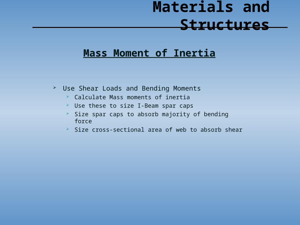
Use Shear Loads and Bending Moments Calculate Mass moments of inertia Use these to size I-Beam spar caps Size spar caps to absorb majority of bending force Size cross-sectional area of web to absorb shear
Mass Moment of Inertia

Performance
Total Mission Duration 6 hours 56 minutes
Egress and Ingress at M=2
Strike Patrol - Subsonic Velocity for Maximum Endurance (55,000 ft)
Reserves - Subsonic Velocity for Maximum Endurance (Sea Level)
5,685 ft Takeoff distance Ground roll, Transition, and Climb over a 50 ft barrier Thrust capabilities and high L/D enable short TO distance
6,421 ft Landing distance Approach (clearance of 50 ft barrier), Flare, and Ground Roll

Desire Ps=0 contours to envelop those of an opponent
Performance
Sustained Load Factor (Ps = 0)
Sustained Load Factor at Max Thrust (Ps = 0)
0
5
10
15
20
25
30
35
40
45
50
55
60
65
0.0 0.2 0.4 0.6 0.8 1.0 1.2 1.4 1.6 1.8 2.0 2.2 2.4
Mach Number
Alt
titu
de
(1
03 )
n=1
n=3
n=5
n=7
n=9
q Limit
VstallLimit
1-g Specific Excess Power at Max Thrust (Ps)
0
5
10
15
20
25
30
35
40
45
50
55
60
65
0.0 0.2 0.4 0.6 0.8 1.0 1.2 1.4 1.6 1.8 2.0 2.2 2.4
Mach Number
Alt
itu
de
(1
03 )
Ps=0
Ps=100
Ps=300
Ps=500
q Limit
VstallLimit
Specific Excess Power at Max Thrust with n=1

Want Ps Maximized at each energy height to minimize climb time
PerformanceLines of Constant Energy overlaid onto lines of constant Ps (n=1)
1-g Specific Excess Power at Max Thrust (Ps)
0.0
5.0
10.0
15.0
20.0
25.0
30.0
35.0
40.0
45.0
50.0
55.0
60.0
65.0
70.0
0.0 0.2 0.4 0.6 0.8 1.0 1.2 1.4 1.6 1.8 2.0 2.2
Mach Number
Alt
itu
de
(1
03)
5k
10k
15k
20k
25k
30k
35k
40k
45k
50k
55k
60k
65k
70k
75k
80k
85k
90k
95k
100k
105k
Ps=0
Ps=100
Ps=300
Ps=500
q Limit
Vstall Limit

Turn Rate and Corner Speed at Max Thrust (Altitude = 55,000 ft)
0
1
2
3
4
5
6
7
8
9
10
11
12
300 400 500 600 700 800 900
Velocity (ft/s)
Tu
rn R
ate
(d
eg
/s)
n=1.5
n=2
n=3
n=3.89
n=4
n=5
R = 500 ft
R = 750 ft
R = 1000 ft
R = 1250 ft
R = 1500 ft
R = 1750 ft
R = 2000 ft
R = 2250 ft
qinf Limit
Vstall Limit
Ps = 0
Turn Rate and Corner Speed at Max Thrust (Altitude = Sea Level)
0
5
10
15
20
25
30
35
0 150 300 450 600 750 900 1050 1200
Velocity (ft/s)
Tu
rn R
ate
(deg
/s)
n=1.5
n=2
n=3
n=3.89
n=5
n=6
n=7
R =500 ft
R = 750 ft
R = 1000 ft
R = 1250 ft
R = 1500 ft
R = 3000 ft
R = 4000 ft
R = 5000 ft
qinf Limit
Vstall Limit
Ps = 0
PerformanceDog House Plots

Performance
Performance Requirements and Review
Required Actual UnitSupercruise RequirementMach Number in Military Thrust at 55,000 ft 2 2
Subsonic ConfigurationSustain Load Factor - Maximum Thrust
M = 0.7 / Alt = 55,000 ft 3 3.89 g's
Instaneous Turn RateM = 0.7 / Alt = 55,000 ft 7.48 deg/ sM = 0.5735 / Alt = 55,000 ft 6.95 deg/ s
M = 0.7 / Alt = SL 29.4 deg/ s
Subsonic Velocity for best endurance at 55,000 ft - 555 ft/ sMach Number 0.5735
Total Mission Duration 6:55 hr:min
Takeoff Distance 8000 5,685 ft
Landing Distance 8000 6,421 ft
Conclusions
Cost
100 aircraft total purchase
RTD&E: $9,469,990,078
Flyaway: $1,882,680,488
Other costs: $1,135,329,434
Total acquisition: $1.2488x10¹⁰
Unit flyaway cost: $113,526,705.70

Future Work Needed
WING STABILTY IN MORPH!!
CG Maintenance system
Creation of “Belly” material
Wind tunnel testing
Thrust Vectoring
CFD Analysis
Area ruling and minimization of wave drag
Nozzle placement – Trade studies
FEM
Subsystems / Mechanizations

Lessons Learned
Interdependence and communication
Personal responsibility to get the work done
Work for a real life sponsored project
Break the rules of standardization
References and Acknowledgements

References
Raymer, Daniel P. Aircraft Design: A Conceptual ApproachAmerican Institute of Aeronautics and Astronautics, Inc., 1999
Beer, Ferdinand P., DeWolf T. John, and E. Russell Johnston, Jr.Mechanics of MaterialsMcGraw-Hill, 2002.
US Military Aircraft. Federation of American Scientists.
http://fas.org/man/dod-101/sys/ac/
Thrust Specific Fuel Consumption, NASA Glenn Research Centerhttp://www.grc.nasa.gov/WWW/K-12/airplane/sfc.html
F-22 Raptor F119-PW-100 Engine, Globalsecurity.orghttp://www.globalsecurity.org/military/systems/aircraft/f-22-f119.htm
First we’d like to thank the Academy…
Dr. James LangProject Advisor
Charles Chase Lockheed Martin Sponsor
John MeissnerMAE 155 Teaching Assistant
Dr. Vistasp M. KarbhariUCSD Professor of Structural Engineering
Tom ChalfantUCSD MAE Machine Shop Manager
And all of the pilots and jets that fly over UCSD … everyday. Thank You.
Related Documents