SCOPE OF WORK Document Number: XXXX DN100 Powerstation Fuel Feed Line Upgrade Project Page 1 of 34 Revision: 0 Date: 31 October 2016 SCOPE OF WORK DN100 POWERSTATION FUEL FEED LINE UPGRADE PROJECT SERVICES (INCLUDING SPECIFICATIONS) 1. INTRODUCTION 1.1 Purpose This Scope of Work details the Company’s requirements and standards for the Works to be performed by the Contractor under the Contract. 1.2 Background The Lorim Point Fuel Farm transfers diesel fuel from tanks 11 and 12 to the day tanks at Humbug Powerstation via a DN100 carbon steel pipeline. A section of the DN100 pipeline is currently installed underground. Figure 1 below illustrates the DN100 diesel line pipe route from the Fuel Farm to the Humburg Powerstation Day Tanks. Figure 1: DN100 Diesel Fuel Line route The Company wishes to replace and re-route a section of the DN100 Diesel Fuel Line aboveground wherever possible and through culverts wherever required to run below ground, e.g. at road crossings. Figure 2 below illustrates a section of approximately 300m of the DN100 diesel line pipe route which is to be re-routed.

Welcome message from author
This document is posted to help you gain knowledge. Please leave a comment to let me know what you think about it! Share it to your friends and learn new things together.
Transcript

SCOPE OF WORK Document Number: XXXX
DN100 Powerstation Fuel Feed Line Upgrade Project Page 1 of 34
Revision: 0 Date: 31 October 2016
SCOPE OF WORK
DN100 POWERSTATION FUEL FEED LINE UPGRADE
PROJECT
SERVICES
(INCLUDING SPECIFICATIONS)
1. INTRODUCTION
1.1 Purpose
This Scope of Work details the Company’s requirements and standards for the Works to be
performed by the Contractor under the Contract.
1.2 Background
The Lorim Point Fuel Farm transfers diesel fuel from tanks 11 and 12 to the day tanks at Humbug
Powerstation via a DN100 carbon steel pipeline. A section of the DN100 pipeline is currently
installed underground.
Figure 1 below illustrates the DN100 diesel line pipe route from the Fuel Farm to the Humburg
Powerstation Day Tanks.
Figure 1: DN100 Diesel Fuel Line route
The Company wishes to replace and re-route a section of the DN100 Diesel Fuel Line
aboveground wherever possible and through culverts wherever required to run below ground,
e.g. at road crossings.
Figure 2 below illustrates a section of approximately 300m of the DN100 diesel line pipe route
which is to be re-routed.

SCOPE OF WORK Document Number: XXXX
DN100 Powerstation Fuel Feed Line Upgrade Project Page 2 of 34
Revision: 0 Date: 31 January 2017
Figure 2: Illustration of DN100 fuel line to be re-routed.
1.3 Applicable Documents and Standards
The Contractor must ensure that the Services and any Associated Goods, equipment, and
vehicles, must as a minimum, comply with all Company Specifications, Standards and Contract
Drawing documents as set out in Table A1 of this Scope of Work document.
Table A1 - Company Specifications, Standards and Contract Drawings
Document Number Revision Title
CSTL-0150-15 Rio Tinto ASME Pressure Piping Specification
CSSW 449 1 Standard Specification for Piping Materials and
Valves
CSSW-C385 0 Standard Specification for Preparation and Coating
of Steel Surfaces
521 20001 A Diesel Line Upgrade
Road Culvert Crossings
Northern Culvert
521 20002 A Diesel Line Upgrade
Road Culvert Crossings
Southern Culvert
521 20003 A Diesel Line Upgrade
Road Regrading Details
521 30004 A Diesel Line Upgrade
Access Platform Modifications
Sheet 1

SCOPE OF WORK Document Number: XXXX
DN100 Powerstation Fuel Feed Line Upgrade Project Page 3 of 34
Revision: 0 Date: 31 January 2017
521 80012 A Diesel Line Upgrade
General Arrangement
521 80013 A Diesel Line Upgrade
Arrangement
Sheet 1
521 80014 A Diesel Line Upgrade
Arrangement
Sheet 2
521 80015 A Diesel Line Upgrade
Arrangement
Sheet 3
521 80016 A Diesel Line Upgrade
Arrangement
Sheet 4
521 80017 A Diesel Line Upgrade
Arrangement
Sheet 5
521 80018 A Diesel Line Upgrade
Arrangement
Sheet 6
521 80019 A Diesel Line Upgrade
Pipe Support Details
Sheet 1
521 80020 A Diesel Line Upgrade
Pipe Support Details
Sheet 2
521 80021 A Diesel Line Upgrade
Pipe Details
Sheet 1
Prior to commencing the Services, the Contractor must:
(a) obtain a copy of all relevant Company policies and standards from the Company
Representative (if it does not already hold a copy); and
(b) ensure it and its Personnel have read and understood the contents of all documents.
(c) The Contractor acknowledges and agrees that the Company, as originator of any
Documentation contained in Table A1, reserves the right to alter, amend or discard any
of these documents or create new documents.

SCOPE OF WORK Document Number: XXXX
DN100 Powerstation Fuel Feed Line Upgrade Project Page 4 of 34
Revision: 0 Date: 31 January 2017
(d) The Contractor acknowledges that, when the Company changes any of the applicable
documentation contained in Table A1 as per Paragraph 1.3(c) above, a copy of the
most recent document will be made available to the Contractor, which will then take
precedence.
1.4 Australian and International Standards
The Contractor must ensure that the Services meet any applicable laws or Government Agency
requirements (both State and Federal), including but not limited to relevant standards published
by the Standards Australia, and the American Society of Mechanical Engineers Standards
(ASME Standards) or, if there are no such standards, then relevant International Standards.
Australian and International standards relevant to this project include, but are not limited to, those
set out in Table A1 of this Scope of Work document.
Table A2 – Australian and International Standards
Document Number Year Title
AS4041 2006 Pressure Piping
AS4037 1999 Pressure equipment – Examination and testing
AS1345 1995 Identification of the contents of pipes, conduits and
ducts
ASTM A105 Standard Specification for Carbon Steel Forgings for
Piping Applications
ASTM A106 Standard Specification for Seamless Carbon Steel
Pipe for High-Temperature Service
1.5 Precedence of Documents in Scope of Services
This Scope of Work document may contain references to various documents and in the event of
any inconsistency between this Scope of Work document and a document referenced within this
document, unless otherwise provided, the documents will rank in order of precedence in the order
in which they are listed below:
(a) this Scope of Work document;
(b) the Company’s Specifications, Standards and Contract Drawings, as listed in Table A1;
(c) relevant Australian and International Standards, as listed in Table A2; and
(d) any other documents listed in this Scope of Work document.
1.6 Acknowledgement of Process Materials
The Contractor acknowledges that there is a fully operational bauxite processing plant at the Site
and any equipment (including motor vehicles) brought onto the Site by the Contractor or its
Personnel may be exposed to process materials and agrees to bear the risk in this regard. The
Contractor acknowledges that the Company will not be liable for any damage to or loss of such
equipment caused by exposure to or contact with process materials.

SCOPE OF WORK Document Number: XXXX
DN100 Powerstation Fuel Feed Line Upgrade Project Page 5 of 34
Revision: 0 Date: 31 January 2017
2. GENERAL REQUIREMENTS
2.1 General
In completing the Services, the Contractor must:
(a) provide a single point of contact (project manager) who will be fully responsible for the
execution of the Services and all Site safety;
(b) complete a detailed constructability review and risk assessment for the project;
(c) ensure that the works that it performs meet the requirements as set out in drawings,
specifications, and standards identified in the Contract;
(d) provide all Personnel required to successfully complete the Services, including Site
trained and qualified permit recipients;
(e) ensure that all its Personnel comply with all Company policies and standards, including,
but not limited to:
(i) holding current Site-specific medical certification;
(ii) successfully complete all Site and area inductions;
(iii) have and maintain any relevant Site Competent to Operate (CTO) to operate
machinery and equipment;
(iv) have and maintain statutory licences, such as electrical, demolition or plumbing
licences; and
(v) Job Hazard Analysis (JHA) preparation.
(f) ensure that all Personnel wear appropriate safety equipment at all times;
(g) supply all tools and equipment required to complete the Services, including, but not
limited to:
(i) scaffolding;
(ii) mobile equipment;
(iii) pipe draining, pipe cleaning (pigging) and hydrotesting equipment;
(iv) cranes; and,
(v) temporary power supplies, including extension leads.
(h) ensure that all fixed and mobile plant, tools or equipment are approved for use on Site;
(i) prepare and submit for approval by the Company Representative, inspection and test
plans (ITPs);
(j) provide qualified work procedures for the Services;
(k) complete visual inspections with the Company Representative or appointed delegate
prior to sign off;
(l) provide a complete manufacturer’s data report (MDR);
(m) compile a daily shift log and site diary of work, progress and delays to be countersigned
by the Company’s Project Representative on a daily basis;
(n) within 2 weeks of completion of hydrotesting, provide all red-lined marked-up drawings
in hard copy and electronic formats; and,
(o) maintain a clean work area and complete a final clean-up of the area to the satisfaction
of the Company.

SCOPE OF WORK Document Number: XXXX
DN100 Powerstation Fuel Feed Line Upgrade Project Page 6 of 34
Revision: 0 Date: 31 January 2017
2.2 Procurement
The Contractor must complete all procurement activities required to successfully complete the
Services to the stated quality and schedule objectives.
2.3 Transportation to Site
The Contractor is responsible for loading, transport, delivery and offloading of all equipment and
materials to Site. A laydown area will be provided by the Company.
2.4 Access
The Contractor is responsible for the provision of all access services required to complete the
Services. If scaffolding is required as an access method:
(a) scaffolding locations must be approved by the Company Representative; and
(b) scaffolding must be in accordance with the Company’s standard.
2.5 Workshop Inspection
(a) The Company reserves the right to conduct workshop inspections of the Services at the
Contractor’s premises as and when required.
(b) Inspections will be of a general nature only to monitor progress and performance and
the Contractor acknowledges and agrees that no fabrication errors will be deemed as
accepted by the Company as a result of these inspections.
2.6 Civil Works
The Contractor must complete all procurement and installation of all culverts, pipe support
footings and other civil materials and equipment required for this scope of Services in accordance
with Company standards.
2.7 Electrical Works
The Contractor must complete all modifications to existing electrical equipment as required for
this scope of Services in accordance with Company standards.
2.8 Structural Works
The Contractor must complete all procurement, fabrication, blasting and painting and installation
of all new piping structural supports, and modification to existing steelwork structures where
required, for this scope of Services in accordance with Company standards.
2.9 Piping Works
The Contractor must complete all procurement, fabrication, blasting and painting, installation and
hydrotesting of all piping materials. The following must be completed by the Contractor:
(a) transport to Site and prepare all materials;
(b) install pipe sections between nominated tie-in points, including structural and pipe
supports as per Section 5;
(c) obtain isolations as required;
(d) complete installation at tie-in points during planned shutdown, including drainage of
existing pipeline and local removal and disposal in the Company’s scrap metal bins of
minor sections of redundant pipe and pipe supports, plus any make-safe activities for
the redundant pipe remaining underground;
(e) complete all non-destructive testing (NDT), post weld heat treatment (PWHT) and stress
relieving activities in accordance with the Company’s standards and specifications;

SCOPE OF WORK Document Number: XXXX
DN100 Powerstation Fuel Feed Line Upgrade Project Page 7 of 34
Revision: 0 Date: 31 January 2017
(f) successfully complete hydrotesting;
(g) return isolation;
(h) complete ‘As-Built’ survey of final pipe route and provide the Company with survey files
in .dwg electronic format;
(i) complete red-line marked-up drawings in .pdf format; and,
(j) clean-up and general housekeeping to Company’s satisfaction.
2.10 Hydrotesting
The Contractor must provide hydrotesting at the site.
The hydrotesting must include a detailed inspection by the Contractor of the equipment to assess
its condition and ability to operate to the desired efficiency.
The Contractor must provide the appropriate consumables and spares required for hydrotesting.
The Contractor must advise the Company of the services, facilities and Company Personnel
required to perform the hydrotesting.
Upon successfully completing the hydrotesting the Contractor shall include the hydrotest report
as part of the MDR submission.
2.11 Other Work Groups
The Contractor acknowledges that there may be other work groups in the work area at the time
of the Services. The Contractor must take care not to impinge upon their works and clearly
demarcate their worksite.
2.12 Isolations
The Contractor must provide a minimum of 48 hours’ notice to the Company Representative
ahead of any required isolation. The isolation request must include:
(a) the equipment required to be isolated;
(b) date and time required to be isolated; and
(c) duration of the isolation.
2.13 Underground services
The Contractor acknowledges that some underground services may not be identified on
Company As-Built drawings. The Contractor shall be responsible to obtain site dig permits, shall
use ‘Hydrovac’ trucks to expose all buried services and shall complete all excavation works in
accordance with Company standards and procedures.
The Contractor shall stop work immediately and contact the Company Project Representative if
any underground services are struck.

SCOPE OF WORK Document Number: XXXX
DN100 Powerstation Fuel Feed Line Upgrade Project Page 8 of 34
Revision: 0 Date: 31 January 2017
3. QUALITY
3.1 General
The Contractor must have a Quality Management System which has been certified by a
certification body acceptable to the Company. The certification must include design and
development activities if these activities are required under the Contract.
If requested to do, so the Contractor must supply to the Company a quality plan which must:
(a) document how the requirements of the Contract will be met and what documents will be
used to assure compliance, including Sub-contractors’ and suppliers’ work;
(b) identify and trace the components of the Contract in accordance with Contract
requirements;
(c) provide separate inspection and test plans (Inspection and Test Plans) for each
requirement for each separable component of the Contract, with hold or witness points
for inspection, testing and verification as required under the Contract;
(d) identify any non-conforming components. The Contractor must advise the Company of
any non-conforming component and submit for approval, a proposal on addressing the
non-conformance by either:
(i) waiver;
(ii) rework;
(iii) repair; or
(iv) replacement; and
(v) record the approved disposition of the non-conformance; and,
(e) upon completion of inspections and tests, be updated with documents as necessary to
verify that the components conform to the Contract requirements.

SCOPE OF WORK Document Number: XXXX
DN100 Powerstation Fuel Feed Line Upgrade Project Page 9 of 34
Revision: 0 Date: 31 January 2017
4. WELDING SCOPE
4.1 Welding Standards
On Site welding will be required as part of the Services and the welding must be completed in
accordance with this Scope of Work document, technical specifications, Company standards and
the latest versions of the Australian and International Standards relevant to this project.
4.2 Welding Package
The Contractor must prepare and submit a welding package to the Company project
representative prior to the start of welding. The package must include:
(a) Project drawings;
(b) ITPs;
(c) welding procedure specifications (WPS) and procedure qualifications records (PQRs);
(d) welder qualification register and records of applicable welders; and,
(e) nominated welding supervisor’s certification.
The ITP must identify the above items as steps of review by the Company Project
Representative. The Company Project Representative will then sign the applicable items as
reviewed and may add additional requirements and inspection hold points for ITP revision.
The Contractor must provide and nominate a person to carry out the role of welding supervisor.
This person must visit the job site on a 1-2 week basis and will be accountable to the Company
for the Contractor’s in-process welding inspection and welding quality assurance.
The Contractor’s welding supervisor must hold and maintain:
(a) WTIA AS1796 Certified Welding Supervisor or equivalent; for all Pressure Piping
activities; and
(b) WTIA AS2214 Welding Supervisor for Structural welding activities.
4.3 Welding NDT
All welding must be 100% visually inspected by a welding supervisor or certified welding
inspector representing the Contractor. The welding supervisor must sign the ITP at all necessary
points. All welding NDT must be completed by a National Association of Testing Authorities
(NATA) certified contractor approved by the Company and must be independent from the welding
contractor. Unless authorised by the Company Project Representative, all non-destructive
examinations (NDE) technicians must be NATA registered and certified and all reports must have
the NATA endorsement logo displayed. A minimum 10% of all welds are to be NDT inspected.
4.4 Company’s Welding Inspections
Company’s welding inspection activities as per the approved ITP will be carried out by the
Company Project Representative, or delegated representative. The Contractor must give the
Company Project Representative, or delegated representative, at least 24 hours’ notice of
readiness for inspections.
4.5 Welding Requirements
After the completion of the welding operation the welder must record beside each weld using
paint pen or other permanent marker the following details:
(a) date;
(b) WPS number;

SCOPE OF WORK Document Number: XXXX
DN100 Powerstation Fuel Feed Line Upgrade Project Page 10 of 34
Revision: 0 Date: 31 January 2017
(c) welder ID number; and
(d) W/S sign off (must be completed by Contractor’s welding supervisor).
4.6 Post Weld Heat Treatment
Where required, post weld heat treatment must be completed as per Company Specifications
and Australian Standards.
4.7 Manufacturer’s Data Report
The Contractor must provide a complete draft MDR within one (1) week and final MDR within
three (3) weeks after completion of the Services in pdf. format and completely legible, including:
(a) the ITP signed on every line by responsible Personnel and signed by the Company
welding advisor at the required review/hold/witness points;
(b) PQRs;
(c) WPSs;
(d) welder qualification register and qualification records;
(e) material register and mill certificates;
(f) consumable register and certificates;
(g) weld maps and weld traceability;
(h) post weld heat treatment request, reports and charts NDT request and reports;
(i) hydrotest reports;
(j) visual inspection certificate approved and signed by certified welding
supervisor/inspector;
(k) painting quality assurance check sheets and reports (if applicable); and
(l) Non-conformance reports (NCRs) and concessions (if applicable).

SCOPE OF WORK Document Number: XXXX
DN100 Powerstation Fuel Feed Line Upgrade Project Page 11 of 34
Revision: 0 Date: 31 January 2017
5. WORK SCOPE
5.1 Battery Limits
The Contractor acknowledges and agrees that the following are the battery limits for the Scope
of Work:
(a) DN100 pipe at ‘Fuel Farm’ side tie-in location as illustrated in contract drawings and
Figures 3 and 4 below.
Figure 3: Battery limit at 'Fuel Farm' side tie-in location: DN100 pipe
Figure 4: Battery limit at 'Fuel Farm' side tie-in location: DN100 pipe
(b) DN100 valve flange face at ‘Powerstation’ side tie-in location, as illustrated in Figures 5
and 6 below.

SCOPE OF WORK Document Number: XXXX
DN100 Powerstation Fuel Feed Line Upgrade Project Page 12 of 34
Revision: 0 Date: 31 January 2017
Figure 5: Battery limit at 'Powerstation' side tie-in location: DN100 valve flange
Figure 6: Battery limit at 'Powerstation' side tie-in location: DN100 valve flange
(c) Underside new pipe support footings.
(d) Underside new and existing pipe supports where pipework supports are to be connected
to existing structures, including but not limited to: overhead walkways, cable tray support
structures, concrete walls.
5.2 Tie-In Works
The Contractor must follow the design for tie-in works as per supplied Company drawings.
The Contractor must provide the Company with a tie-in work shutdown schedule for review and
approval.
The Contractor shall drain and flush pipelines and execute any other works deemed required to
safely tie into the existing fuel line, as part of the Contractor’s Scope of Work.
Figures 3, 4, 5 and 6 identify the tie-in work locations for this project which are:
(a) ‘Fuel Farm’ side tie-in (DN100 pipe – to be cut into at location nominated on Contract
drawings); and,
(b) ‘Powerstation’ side tie-in (DN100 isolation valve).
5.3 Pipe Installation Details
The Contractor shall install the new DN100 pipework and associated materials in accordance to
the documentation listed in Section 1.3 of this scope of works document.

SCOPE OF WORK Document Number: XXXX
DN100 Powerstation Fuel Feed Line Upgrade Project Page 13 of 34
Revision: 0 Date: 31 January 2017
The scope of works includes, but is not limited to, the following:
(a) ‘Fuel Farm’ side and ‘Powerstation’ side tie-ins;
(b) DN100 pipe to include drain point near ‘Fuel Farm’ side tie-in location as illustrated in
Figure 7 and as per Company drawings. Contractor to confirm no clash with existing
column member or existing pipework.
Figure 7: DN100 drain poing to be installed
(c) DN100 pipe to be routed from tie-in location to Polishing Dam wall as illustrated in Figure
8. Pipe supports and drain point to be installed as per Company drawings.
Figure 8: DN100 pipe to run from tie-in location to alongside Polishing Dam wall.
(d) DN100 pipe to be installed alongside Polishing Dam wall as illustrated in Figure 9. (pipe
to be protected by Armco barricading). Pipe to be supported via pipe supports as per
Company drawings.

SCOPE OF WORK Document Number: XXXX
DN100 Powerstation Fuel Feed Line Upgrade Project Page 14 of 34
Revision: 0 Date: 31 January 2017
Figure 9: DN100 fuel line to be installed alongside Polishing Dam wall.
(e) Diesel line to be routed behind stairway and ladder, illustrated in Figures 10, 11 and 12.
Stairway to be modified to eliminate clash and allow pipe installation, in accordance with
Contract drawings. Existing pipework to be re-routed.
Figure 10: New DN100 line to be routed behind stairway and ladder.
Figure 11: DN100 pipe to be routed behind stairway. Stairway to be modified and existing
polyethylene pipe to be re-routed.

SCOPE OF WORK Document Number: XXXX
DN100 Powerstation Fuel Feed Line Upgrade Project Page 15 of 34
Revision: 0 Date: 31 January 2017
Figure 12: DN100 pipe to be routed behind ladder.
(f) Safety bollard and Armco barricading to be installed in accordance with Company
drawings, to protect new DN100 diesel line, as illustrated in Figure 13.
Figure 13: Safety bollard and Armco barricading to be installed to protect new DN100 pipeline.
(g) New DN100 pipe to be routed along top of dam bunded wall, as illustrated in Figure 14.
Pipe supports to be fixed to dam wall as per Company drawings. Pipework and supports
to be installed clear of existing services and infrastructure. Where clashes occur,
existing pipework to be modified to allow installation of new DN100 pipework, as
illustrated in Figure 15.

SCOPE OF WORK Document Number: XXXX
DN100 Powerstation Fuel Feed Line Upgrade Project Page 16 of 34
Revision: 0 Date: 31 January 2017
Figure 14: Pipework to be installed along top of bunded wall.
Figure 15: Existing pipework to be modifed to allow installation of new DN100 pipework.
(h) New DN100 pipe to be routed under existing stairway, on top of bunded wall, as
illustrated in Figure 16 and 17. Pipe supports to be installed as required.
Figure 16: New DN100 pipework to run along dam wall and underneath stairway.
SCOPE OF WORK Document Number: XXXX
DN100 Powerstation Fuel Feed Line Upgrade Project Page 17 of 34
Revision: 0 Date: 31 January 2017
Figure 17: New DN100 pipework to be installed underneath existing stairway.
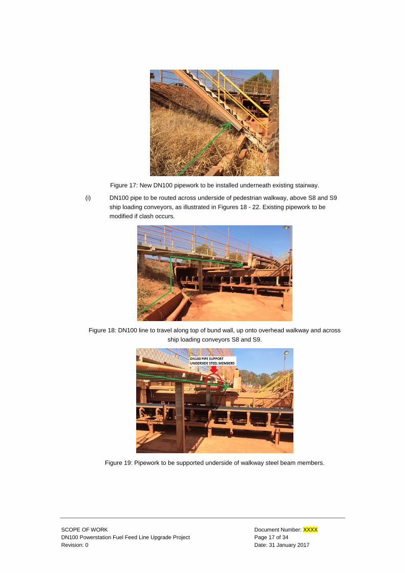
(i) DN100 pipe to be routed across underside of pedestrian walkway, above S8 and S9
ship loading conveyors, as illustrated in Figures 18 - 22. Existing pipework to be
modified if clash occurs.
Figure 18: DN100 line to travel along top of bund wall, up onto overhead walkway and across
ship loading conveyors S8 and S9.
Figure 19: Pipework to be supported underside of walkway steel beam members.

SCOPE OF WORK Document Number: XXXX
DN100 Powerstation Fuel Feed Line Upgrade Project Page 18 of 34
Revision: 0 Date: 31 January 2017
Figure 20: DN100 pipework to travel over cable trays and provide adequate clearance at tunnel
access roadway.
Figure 21: Existing pipework to be modified if clash occurs.
Figure 22: DN100 pipe to be diverted to ‘fence side’ of cable tray rack.
(j) DN100 pipe to be routed on southern side of cable tray support structure, mounted on
new pipe supports which are to be connected to the cable tray support posts. Refer
Figures 23, 24 and 25

SCOPE OF WORK Document Number: XXXX
DN100 Powerstation Fuel Feed Line Upgrade Project Page 19 of 34
Revision: 0 Date: 31 January 2017
Figure 23: DN100 pipework to be supported from cable tray posts, southern / fence side.
Figure 24: DN100 pipework to travel along fence side of cable tray racks, supported off new
pipe support brackets.
Figure 25: DN100 pipe to run along fence side of cable tray rack, towards MCC building.
(k) Diesel line to run around fence line, behind MCC building and transformer as
illustrated in Figures 26 and 27. Pipe supports and Armco barricading to be installed
as per Company drawings.

SCOPE OF WORK Document Number: XXXX
DN100 Powerstation Fuel Feed Line Upgrade Project Page 20 of 34
Revision: 0 Date: 31 January 2017
Figure 26: DN100 fuel line to be routed around back of MCC building, along fence line.
Figure 27: New fuel line to travel around back of transformer, along fence line.
(l) Diesel line to be routed around fence line and through new culvert, across the road
shown in Figures 28, 29 and 30. Gate to be relocated as per Figure 29.
Figure 28: DN100 pipe to travel along fence line and through underground road culvert.

SCOPE OF WORK Document Number: XXXX
DN100 Powerstation Fuel Feed Line Upgrade Project Page 21 of 34
Revision: 0 Date: 31 January 2017
Figure 29: Existing gate to be relocated to eliminate trip hazard.
Figure 30: New DN100 line to run inside culvert across roadway.
(m) DN100 line to be routed along fence line, on pipe supports as per Company drawings
and as illustrated in Figures 31 and 32. Drain point to be installed.
Figure 31: DN100 pipework to travel along fence line.

SCOPE OF WORK Document Number: XXXX
DN100 Powerstation Fuel Feed Line Upgrade Project Page 22 of 34
Revision: 0 Date: 31 January 2017
Figure 32: DN100 pipeline to follow fence line before being routed through new underground
culvert, across roadway.
(n) DN100 diesel line to run through new underground culvert, across Admin Road, in
accordance with Company drawings. Refer images 33 and 34. Drain point and sump
to be installed.
Figure 33: DN100 pipeline to travel below roadway, inside underground culvert.
Figure 34: New culvert to be installed underneath roadway for new DN100 diesel fuel line.
(o) DN100 pipe to be routed aboveground, terminating at ‘Powerstation’ side tie-in
location as illustrated in Figures 35 and 36.

SCOPE OF WORK Document Number: XXXX
DN100 Powerstation Fuel Feed Line Upgrade Project Page 23 of 34
Revision: 0 Date: 31 January 2017
Figure 35: DN100 fuel line to be routed to 'Powerstation' side tie-in location. Barricading to be
installed to protect pipework.
Figure 36: New DN100 diesel line to tie-in to DN100 isolation valve flange.
(p) Label new pipework with ‘FUEL LINE’ text and paint stripes at intervals identified by
Contract drawings and Australian Standard AS1345, and as the same as that illustrated
in Figure 37.

SCOPE OF WORK Document Number: XXXX
DN100 Powerstation Fuel Feed Line Upgrade Project Page 24 of 34
Revision: 0 Date: 31 January 2017
Figure 37: New pipework to be labelled as per existing fuel line pipework illustrated here.
(q) Once tie-ins are complete and new line in service, redundant pipe and associated
anchor block and barricading are to be removed and areas made safe. Sections of
piping to be removed are identified in Figures 38 - 41.
Figure 38: Redundant DN100 pipe to be removed and area made safe.
Figure 39: Redundant DN100 pipework and pipe supports to be removed. Area to be
made safe.

SCOPE OF WORK Document Number: XXXX
DN100 Powerstation Fuel Feed Line Upgrade Project Page 25 of 34
Revision: 0 Date: 31 January 2017
Figure 40: Redundant anchor block to be demolished and area made safe.
Figure 41: Redundant DN100 pipework and asociated barricading to be removed and area
made safe.
(r) Location of identified buried services, where new culverts are to be installed, illustrated
in Figure 42. Note that unidentified additional buried services may also exist in these
locations - hydrovac trucks are required to initially expose all buried services.

SCOPE OF WORK Document Number: XXXX
DN100 Powerstation Fuel Feed Line Upgrade Project Page 26 of 34
Revision: 0 Date: 31 January 2017
Figure 42: Illustration of identified underground services at road crossings.

SCOPE OF WORK Document Number: XXXX
DN100 Powerstation Fuel Feed Line Upgrade Project Page 27 of 34
Revision: 0 Date: 31 January 2017
6. COMPANY SUPPLY
6.1 Items Supplied by the Company
Where appropriate and available, the Company will provide the following at its cost for non-
exclusive use by the Contractor solely in the performance of the Services, upon reasonable
request from the Contractor Representative:
(a) laydown area;
(b) all isolations.
Risk in any Company or third party supplied equipment will pass to and remain with the
Contractor whilst in the Contractor’s care, custody and control.

SCOPE OF WORK Document Number: XXXX
DN100 Powerstation Fuel Feed Line Upgrade Project Page 28 of 34
Revision: 0 Date: 31 January 2017
7. CONTRACTOR SUPPLY
7.1 Items Supplied by the Contractor
Unless otherwise agreed between the Company and the Contractor, the Contractor must, as part
of the Services, supply the following:
(a) all Contractor equipment, tools, consumables and materials to perform or complete the
Services including, but not limited to:
(i) crib facilities;
(ii) ablution facilities;
(iii) personal isolation locks;
(iv) accommodation (if required);
(v) flights (if required);
(vi) vehicle hire (if required);
(vii) forklifts, generators, compressors, lighting towers;
(viii) hydrovac trucks, excavators, cranes, compactors;
(ix) hydrotest tools and equipment;
(x) pipe cleaning tools and equipment, e.g. pigging equipment;
(xi) temporary fencing for laydown areas;
(xii) scaffold;
(xiii) pipping, bends, flanges, etc. as per isometric drawings;
(xiv) fasteners, gaskets, U-bolts and other miscellaneous consumables;
(xv) pipe supports;
(xvi) new signage (posts and pipe labels);
(xvii) road culverts;
(xviii) welding equipment and welding consumables;
(xix) hand tools;
(xx) power tools;
(xxi) consumables;
(xxii) fuel;
(xxiii) screens, blankets and any materials required to manage hot work; and,
(xxiv) drinking water facilities and water containers;
(b) Company-approved and Site-compliant Personal Protective Equipment (PPE)
including, but not limited to:
(i) high-visibility clothing;
(ii) steel-capped boots;
(iii) helmets;
(iv) respirators;
(v) hearing protection;

SCOPE OF WORK Document Number: XXXX
DN100 Powerstation Fuel Feed Line Upgrade Project Page 29 of 34
Revision: 0 Date: 31 January 2017
(vi) head lamps;
(vii) hot work and welding gear;
(viii) gloves;
(ix) jackets; and,
(x) wet weather supplies (e.g. rain coats).

SCOPE OF WORK Document Number: XXXX
DN100 Powerstation Fuel Feed Line Upgrade Project Page 30 of 34
Revision: 0 Date: 31 January 2017
8. MEETINGS
8.1 Risk Assessment & Constructability Review
The Contractor must attend and participate in a risk assessment and constructability review prior
to mobilisation of Personnel, equipment and materials and prior to the commencement of any
fabrication works.
The Contractor must present a draft Project Execution Plan (PEP) document for Company review
a minimum ten (10) working days before the constructability review and risk assessment meeting.
The PEP will be discussed at the Constructability Review and Risk Assessment meeting. The
PEP must include, but not be limited to:
(a) Project constructability methodology;
(b) Proposed roster and working hours;
(c) Key personnel organisation chart, including, but not limited to:
(i) Project manager;
(ii) Surveying;
(iii) Welding inspector;
(iv) Independent NDT company and other subcontractors;
(v) Safety representative; and,
(vi) Project scheduler.
(d) Project schedule;
(e) Resources schedule;
(f) Wet Weather Plan, showing its strategy for managing the effects of wet weather
throughout the provision of the Services, including, but not limited to, the following:
(i) provision of safe access onto and from the Site work fronts;
(ii) management of electrical equipment by the Contractor to allow work to
continue in inclement weather conditions;
(iii) proposed redeployment of work forces to dry areas in the case of inclement
weather; and
(iv) the impacts of wet weather to costs.
(g) MDR template; and,
(h) Project Inspection and Test Plans.
The Contractor must also review and verify the isometric drawings and proposed pipe route prior
to the Constructability Review meeting. The Contractor shall raise any concerns with the
Company at the Constructability Review meeting, such that mistakes can be rectified prior to
commencement of fabrication and installation activities.
After the Constructability Review meeting, the Contractor must incorporate the feedback and
make changes to the PEP before issuing for Client Approval.
8.2 Daily Pre-start
The Contractor must facilitate and run daily pre-start meetings with all Contractor Personnel
which must include the following, at a minimum:

SCOPE OF WORK Document Number: XXXX
DN100 Powerstation Fuel Feed Line Upgrade Project Page 31 of 34
Revision: 0 Date: 31 January 2017
(a) safety performance review of previous shift and focus for the upcoming shift;
(b) Company issued safety toolbox topics if supplied;
(c) A short review of previous shift activities and upcoming shift activities with a focus on
health, safety and environment.
8.3 Safety Interaction and Pauses
The Contractor Personnel must attend and participate in safety interactions and pauses as
deemed appropriate by the Company Representative.
8.4 Other Meetings
The Contractor and its Personnel must attend and participate in all other meetings as deemed
necessary from time to time by the Company Representative.

SCOPE OF WORK Document Number: XXXX
DN100 Powerstation Fuel Feed Line Upgrade Project Page 32 of 34
Revision: 0 Date: 31 January 2017
9. REPORTING
9.1 Shift Report
The Contractor must complete and submit a daily shift log to the Company Representative. This
must be submitted at the end of each shift and cover at a minimum:
(a) a summary of significant work undertaken for the shift (including that by Subcontractors);
(b) a summary of the significant work planned for the following shift (including that by
Subcontractors);
(c) a summary of any health, safety or environmental incidents;
(d) progress versus the schedule of works submitted;
(e) a summary of the incomplete scheduled work for that shift along with the reason;
(f) a resource report detailing all resources utilised for the shift;
(g) list of all major equipment on site, if applicable;
(h) any NDT or Subcontractor generated reports for the shift; and,
(i) a summary of any variations, deviations or emergent work encountered during the shift.

SCOPE OF WORK Document Number: XXXX
DN100 Powerstation Fuel Feed Line Upgrade Project Page 33 of 34
Revision: 0 Date: 31 January 2017
10. SERVICE STANDARD
10.1 Standards of Services
Without limiting the standards as set out elsewhere in this Contract, the Contractor must:
(a) do all things necessary to provide safe, cost effective, efficient and environmentally
friendly Services;
(b) at all times, act in the best interests of the Company;
(c) use all reasonable efforts to continuously improve the process for carrying out the
Services;
(d) take a pro-active role in managing the Services and bring to the attention of the
Company any matter which may threaten plant integrity or reliability; and
(e) obtain the Company’s prior written approval for:
(i) mobilisation of resources or its Personnel to Site;
(ii) any additional off Site work or training that the Company may incur costs for;
(iii) changes to the scope of Services;
(iv) potential cost variations incurred due to events outside the Contractor’s control
which has potential to impact execution of agreed Services within the Services
Timetable or Contract Price (e.g. wet weather, permit delays);
(v) changes in the number of Contractor Personnel engaged in the Services;
(vi) changes to leadership Personnel;
(vii) changes to the work rosters;
(viii) hours worked in excess of the agreed work roster;
(ix) changes to the agreed Services Timetable;
(x) the provision of any resources additional or different to those agreed (including
the composition of those resources). The Contractor acknowledges and
agrees that:
any resources, including labour, tooling or equipment, that are non-
conformant to this Contract will be removed from Site; and,
it will be responsible for all costs in connection with the replacement
of such resources which may include the cost of additional travel for
Non-Local Labour, training and induction costs or transport for
associated equipment;
(xi) positioning of scaffolds;
(xii) returning any Contractor Personnel to work after an injury or incident;
(xiii) closure of plant; and,
(xiv) any stand down time, or demobilisation of labour resources.
10.2 Work Area
Throughout the Term, the Contractor must keep their on-Site working area safe and free from
the accumulation of waste material as a result of performing the Services. Upon completion of
each task, the Contractor must return the on-Site working area to the condition it was found in,

SCOPE OF WORK Document Number: XXXX
DN100 Powerstation Fuel Feed Line Upgrade Project Page 34 of 34
Revision: 0 Date: 31 January 2017
removing all waste, vehicles, plant, equipment and surplus materials in accordance with the
Company’s environmental and waste management standards.
10.3 Re-Work
The Contractor acknowledges and agrees that, without in any way limiting the rights of the
Company under this Contract or generally, re-work resulting from poor workmanship, including
non-compliance to all items contained in this scope of work document, will be at the Contractor’s
expense.
Related Documents