SCI STANTON CONCEPTS, LLC Han Fey Lock Technologies - RKS Robo-Key System - April 2007 – version 1.0 1 /43 The RKS (Robo-Key System) “A Revolutionary Concept” My name is Han Fey and as a collector of high security locks, I am interested in the techniques behind the security that they afford. As a mechanical engineer I take great pleasure in disassembling locks and from that, learning their internal workings. I have at the moment, about 2100 different locks from all over the world. The goal of this article is, just like with all of my articles to inform people about existing and /or new locking mechanisms. If you see me as an extension of the lock industry and you see my articles as marketing instruments, please do not read further. During my many lock collection activities, I met Bob Loughlin. He is also a lock collector with more then 1500 locks in his collection. We traded some locks and a friendship was born. He showed me the RKS lock in September 2005 when he was in Amsterdam for a short stay. They (Stanton Concepts) were working on this concept. Immediately, I saw the link of this lock concept along with both Abloy and the S&G safe lock combination system. I was very pleasantly surprised by the effectiveness and security possibilities of this system. I was allowed by Bob to have an in depth look at his new “RKS” lock. It is from this close examination that this article is possible. In the current timeframe, this locking system is not yet in production; however it is my expectation that it will soon start being manufactured. I have now had the opportunity to closely examine multiple generations of prototypes of the RKS lock. I have studied them carefully and I found it worth writing an article about them. In Sneek, Netherlands, during the weekend of the Dutch Open, which was held during November 2006, this lock was demonstrated to lock pickers from the USA, UK, France, Germany, The Netherlands, etc. We had a brainstorming session regarding this lock and quite few proposals for improvements came out this brainstorm. Encouraged by this interest, the inventor determined that he had very adequate reasons to continue with a next generation locking system. I am calling this generation IV, but more about that later. The RKS-system was developed in early 2004 by Stanton Concepts, (SCI) an intellectual property company. Stanton Concepts is a father (Bob Loughlin) and son (John) team who together have more then 50 years experience in the field of physical security. At first they called this locking system the TOC (Tool Operated Combination lock). Tool operated means that the key had a motor in it, to rotate the discs in the cylinder. Because the key in the system got more extra features, they started to name that specific part a Robo Key. In Gen IV, they started to call the system RKS. The technologies that I write about in this article are based upon my observations from working with parts of my collection. Please be advised I disclaim liability for any errors within this article’s content. However, I have done my best to record it as accurately as possible. For errors and suggested corrections, see the end of the document for my contact details. The Robo-Key System lock (former TOC principle) A Mix Of The Best of Abloy and S&G Locking Systems

Welcome message from author
This document is posted to help you gain knowledge. Please leave a comment to let me know what you think about it! Share it to your friends and learn new things together.
Transcript
SCI STANTON CONCEPTS, LLC
Han Fey Lock Technologies - RKS Robo-Key System - April 2007 – version 1.0 1 /43
The RKS (Robo-Key System) “A Revolutionary Concept”
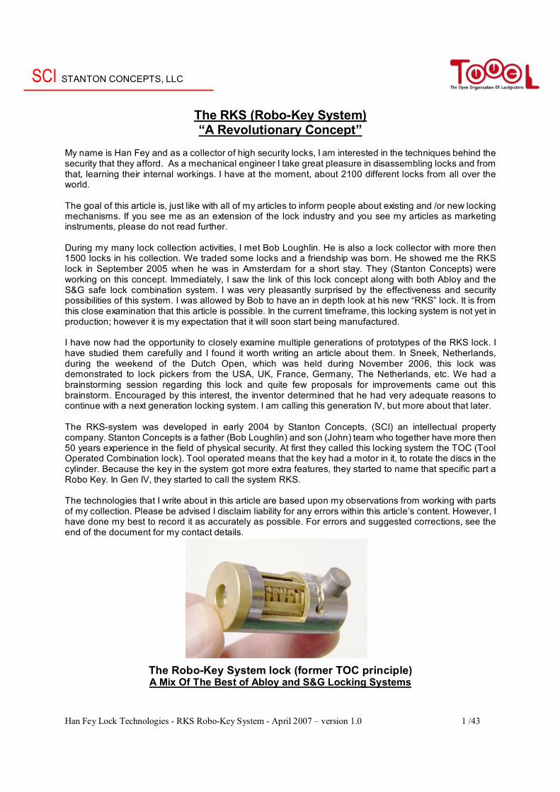
My name is Han Fey and as a collector of high security locks, I am interested in the techniques behind the security that they afford. As a mechanical engineer I take great pleasure in disassembling locks and from that, learning their internal workings. I have at the moment, about 2100 different locks from all over the world. The goal of this article is, just like with all of my articles to inform people about existing and /or new locking mechanisms. If you see me as an extension of the lock industry and you see my articles as marketing instruments, please do not read further. During my many lock collection activities, I met Bob Loughlin. He is also a lock collector with more then 1500 locks in his collection. We traded some locks and a friendship was born. He showed me the RKS lock in September 2005 when he was in Amsterdam for a short stay. They (Stanton Concepts) were working on this concept. Immediately, I saw the link of this lock concept along with both Abloy and the S&G safe lock combination system. I was very pleasantly surprised by the effectiveness and security possibilities of this system. I was allowed by Bob to have an in depth look at his new “RKS” lock. It is from this close examination that this article is possible. In the current timeframe, this locking system is not yet in production; however it is my expectation that it will soon start being manufactured. I have now had the opportunity to closely examine multiple generations of prototypes of the RKS lock. I have studied them carefully and I found it worth writing an article about them. In Sneek, Netherlands, during the weekend of the Dutch Open, which was held during November 2006, this lock was demonstrated to lock pickers from the USA, UK, France, Germany, The Netherlands, etc. We had a brainstorming session regarding this lock and quite few proposals for improvements came out this brainstorm. Encouraged by this interest, the inventor determined that he had very adequate reasons to continue with a next generation locking system. I am calling this generation IV, but more about that later. The RKS-system was developed in early 2004 by Stanton Concepts, (SCI) an intellectual property company. Stanton Concepts is a father (Bob Loughlin) and son (John) team who together have more then 50 years experience in the field of physical security. At first they called this locking system the TOC (Tool Operated Combination lock). Tool operated means that the key had a motor in it, to rotate the discs in the cylinder. Because the key in the system got more extra features, they started to name that specific part a Robo Key. In Gen IV, they started to call the system RKS. The technologies that I write about in this article are based upon my observations from working with parts of my collection. Please be advised I disclaim liability for any errors within this article’s content. However, I have done my best to record it as accurately as possible. For errors and suggested corrections, see the end of the document for my contact details.
The Robo-Key System lock (former TOC principle) A Mix Of The Best of Abloy and S&G Locking Systems
SCI STANTON CONCEPTS, LLC
Han Fey Lock Technologies - RKS Robo-Key System - April 2007 – version 1.0 2 /43
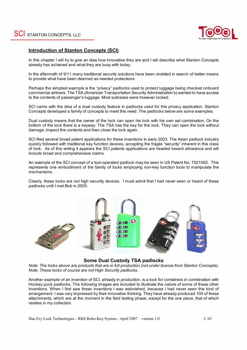
Introduction of Stanton Concepts (SCI) In this chapter I will try to give an idea how innovative they are and I will describe what Stanton Concepts already has achieved and what they are busy with today. In the aftermath of 9/11 many traditional security solutions have been revisited in search of better means to provide what have been deemed as needed protections. Perhaps the simplest example is the “privacy” padlocks used to protect luggage being checked onboard commercial airliners. The TSA (American Transportation Security Administration’s) wanted to have access to the contents of passenger’s luggage. Most suitcases were however locked. SCI came with the idea of a dual custody feature in padlocks used for this privacy application. Stanton Concepts developed a family of concepts to meet this need. The padlocks below are some examples. Dual custody means that the owner of the lock can open his lock with his own set combination. On the bottom of the lock there is a keyway. The TSA has the key for this lock. They can open the lock without damage, inspect the contents and then close the lock again. SCI filed several broad patent applications for these inventions in early 2003. The Asian padlock industry quickly followed with traditional key function devices, accepting the fragile “security” inherent in this class of lock. As of this writing it appears the SCI patents applications are headed toward allowance and will include broad and comprehensive claims. An example of the SCI concept of a tool-operated padlock may be seen in US Patent No. 7021092. This represents one embodiment of the family of locks employing non-key function tools to manipulate the mechanisms. Clearly, these locks are not high security devices. I must admit that I had never seen or heard of these padlocks until I met Bob in 2005.
Some Dual Custody TSA padlocks
Note: The locks above are products that are in full production (not under license from Stanton Concepts). Note: These locks of course are not High Security padlocks. Another example of an invention of SCI, already in production, is a lock for containers in combination with Hockey puck padlocks. The following images are included to illustrate the nature of some of these other inventions. When I first saw these inventions I was astonished, because I had never seen this kind of arrangement. I was very impressed by their innovative thinking. They have already produced 100 of these attachments, which are at the moment in the field testing phase, except for the one piece, that of which resides in my collection.
SCI STANTON CONCEPTS, LLC
Han Fey Lock Technologies - RKS Robo-Key System - April 2007 – version 1.0 3 /43
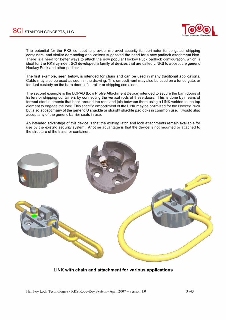
The potential for the RKS concept to provide improved security for perimeter fence gates, shipping containers, and similar demanding applications suggested the need for a new padlock attachment idea. There is a need for better ways to attach the now popular Hockey Puck padlock configuration, which is ideal for the RKS cylinder. SCI developed a family of devices that are called LINKS to accept the generic Hockey Puck and other padlocks. The first example, seen below, is intended for chain and can be used in many traditional applications. Cable may also be used as seen in the drawing. This embodiment may also be used on a fence gate, or for dual custody on the barn doors of a trailer or shipping container. The second example is the LOPAD (Low Profile Attachment Device) intended to secure the barn doors of trailers or shipping containers by connecting the vertical rods of these doors. This is done by means of formed steel elements that hook around the rods and join between them using a LINK welded to the top element to engage the lock. This specific embodiment of the LINK may be optimized for the Hockey Puck but also accept many of the generic U shackle or straight shackle padlocks in common use. It would also accept any of the generic barrier seals in use. An intended advantage of this device is that the existing latch and lock attachments remain available for use by the existing security system. Another advantage is that the device is not mounted or attached to the structure of the trailer or container.
LINK with chain and attachment for various applications
SCI STANTON CONCEPTS, LLC
Han Fey Lock Technologies - RKS Robo-Key System - April 2007 – version 1.0 4 /43
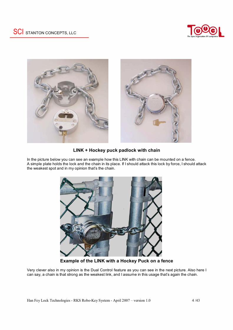
LINK + Hockey puck padlock with chain In the picture below you can see an example how this LINK with chain can be mounted on a fence. A simple plate holds the lock and the chain in its place. If I should attack this lock by force, I should attack the weakest spot and in my opinion that’s the chain.
Example of the LINK with a Hockey Puck on a fence Very clever also in my opinion is the Dual Control feature as you can see in the next picture. Also here I can say, a chain is that strong as the weakest link, and I assume in this usage that’s again the chain.

SCI STANTON CONCEPTS, LLC
Han Fey Lock Technologies - RKS Robo-Key System - April 2007 – version 1.0 5 /43
Dual control feature Hockey puck locks we know already for a long time. With the LINK, the company SCI made a system were they made the hockey puck padlock useable with a chain. They moved the problem of the weak shackle now to the chain. If you see this lock you realize that the shrouded shackle padlocks which protect the shackle for bolt-cutters is only half the solution. A part of the weak shackle remains visible in most shrouded padlocks. Of course there are some exceptions like the Ingersoll CS700 etc. Note: The LINK version shown above is calculated to withstand more than 15,000 KG (33,000 LB) of tensile load.
LOPAD Device for transportation Note: There are three different kinds of padlock shapes used in the above pictures. The padlock right
below is the newest Medeco Gator padlock, which I will discuss in my Medeco article.
SCI STANTON CONCEPTS, LLC
Han Fey Lock Technologies - RKS Robo-Key System - April 2007 – version 1.0 6 /43
The birth of the Robo-Key System The Challenge In the line of their thinking I can imagine that the inventors of SCI saw the need for a better means to secure intermodal shipping containers and similar “barn door” trucks. The high security barrier seals in common use provide only limited utility and traditional key function locks are not practical in the transportation application. The obvious demand for secure, multiple custody locks and reliable audit trail data demonstrated the need for a new idea. The enormous international exchange of intermodal shipping containers in today’s world, threatened by terrorism, represents a major hazard. SCI identified the need for more effective security in this changing world. The reliance on one-time use barrier seals has been the accepted means to deter theft, pilferage and vandalism but is no longer good enough. Traditional key function locks have found little application in this demanding environment. Their limitations are well known and have been tolerated for centuries. Many clever and sophisticated lock mechanisms have evolved that are typically very expensive and fragile but always burdened with the same nagging questions.
- Where is the proper key when I need it? - Has the key been copied or stolen? - Can the lock mechanism be manipulated by any means without
the proper key? - Will the mechanism function reliably?
Today’s urgent demand for the control of space, management of access, comprehensive audit trail data, functional reliability and other difficult considerations represent the challenge that Stanton Concepts addressed with the invention of the Robo-Key System (RKS).
SCI STANTON CONCEPTS, LLC
Han Fey Lock Technologies - RKS Robo-Key System - April 2007 – version 1.0 7 /43
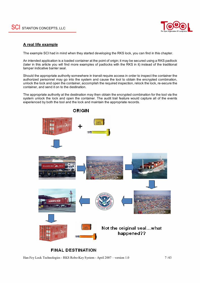
A real life example The example SCI had in mind when they started developing the RKS lock, you can find in this chapter. An intended application is a loaded container at the point of origin; it may be secured using a RKS padlock (later in this article you will find more examples of padlocks with the RKS in it) instead of the traditional tamper indicative barrier seal. Should the appropriate authority somewhere in transit require access in order to inspect the container the authorized personnel may go into the system and cause the tool to obtain the encrypted combination, unlock the lock and open the container, accomplish the required inspection, relock the lock, re-secure the container, and send it on to the destination. The appropriate authority at the destination may then obtain the encrypted combination for the tool via the system unlock the lock and open the container. The audit trail feature would capture all of the events experienced by both the tool and the lock and maintain the appropriate records.
SCI STANTON CONCEPTS, LLC
Han Fey Lock Technologies - RKS Robo-Key System - April 2007 – version 1.0 8 /43
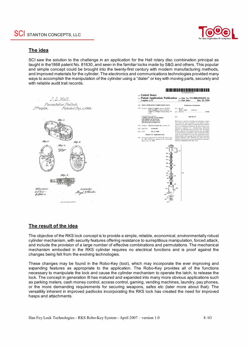
The idea SCI saw the solution to the challenge in an application for the Hall rotary disc combination principal as taught in the1868 patent No. 81630, and seen in the familiar locks made by S&G and others. This popular and simple concept could be brought into the twenty-first century with modern manufacturing methods, and improved materials for the cylinder. The electronics and communications technologies provided many ways to accomplish the manipulation of the cylinder using a “dialer” or key with moving parts, securely and with reliable audit trail records.
The result of the idea The objective of the RKS lock concept is to provide a simple, reliable, economical, environmentally robust cylinder mechanism, with security features offering resistance to surreptitious manipulation, forced attack, and include the provision of a large number of effective combinations and permutations. The mechanical mechanism embodied in the RKS cylinder requires no electrical functions and is proof against the changes being felt from the evolving technologies. These changes may be found in the Robo-Key (tool), which may incorporate the ever improving and expanding features as appropriate to the application. The Robo-Key provides all of the functions necessary to manipulate the lock and cause the cylinder mechanism to operate the latch, to release the lock. The concept in generation III has matured and expanded into many more obvious applications such as parking meters, cash money control, access control, gaming, vending machines, laundry, pay phones, or the more demanding requirements for securing weapons, safes etc (later more about that). The versatility inherent in improved padlocks incorporating the RKS lock has created the need for improved hasps and attachments.
SCI STANTON CONCEPTS, LLC
Han Fey Lock Technologies - RKS Robo-Key System - April 2007 – version 1.0 9 /43
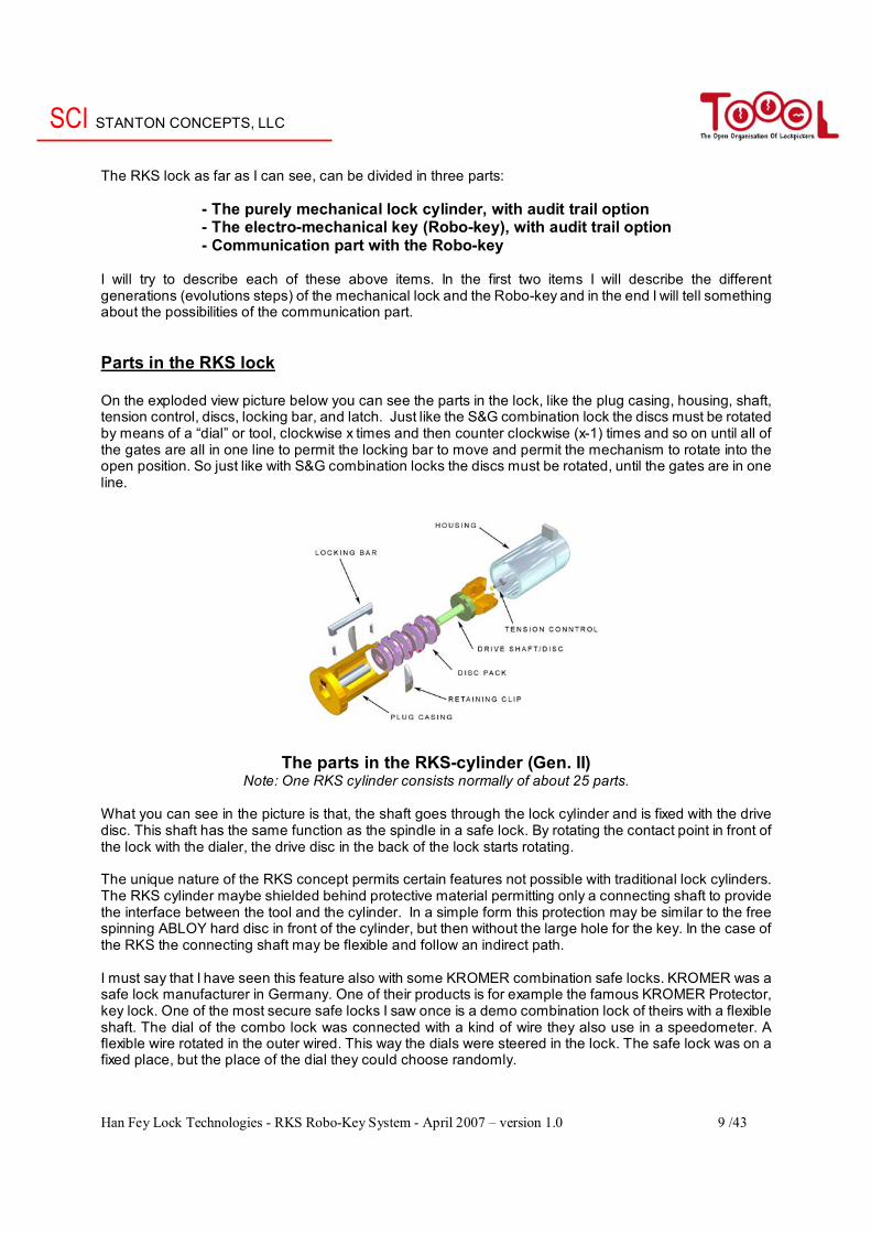
The RKS lock as far as I can see, can be divided in three parts: - The purely mechanical lock cylinder, with audit trail option - The electro-mechanical key (Robo-key), with audit trail option - Communication part with the Robo-key I will try to describe each of these above items. In the first two items I will describe the different generations (evolutions steps) of the mechanical lock and the Robo-key and in the end I will tell something about the possibilities of the communication part. Parts in the RKS lock On the exploded view picture below you can see the parts in the lock, like the plug casing, housing, shaft, tension control, discs, locking bar, and latch. Just like the S&G combination lock the discs must be rotated by means of a “dial” or tool, clockwise x times and then counter clockwise (x-1) times and so on until all of the gates are all in one line to permit the locking bar to move and permit the mechanism to rotate into the open position. So just like with S&G combination locks the discs must be rotated, until the gates are in one line.
The parts in the RKS-cylinder (Gen. II) Note: One RKS cylinder consists normally of about 25 parts.
What you can see in the picture is that, the shaft goes through the lock cylinder and is fixed with the drive disc. This shaft has the same function as the spindle in a safe lock. By rotating the contact point in front of the lock with the dialer, the drive disc in the back of the lock starts rotating. The unique nature of the RKS concept permits certain features not possible with traditional lock cylinders. The RKS cylinder maybe shielded behind protective material permitting only a connecting shaft to provide the interface between the tool and the cylinder. In a simple form this protection may be similar to the free spinning ABLOY hard disc in front of the cylinder, but then without the large hole for the key. In the case of the RKS the connecting shaft may be flexible and follow an indirect path. I must say that I have seen this feature also with some KROMER combination safe locks. KROMER was a safe lock manufacturer in Germany. One of their products is for example the famous KROMER Protector, key lock. One of the most secure safe locks I saw once is a demo combination lock of theirs with a flexible shaft. The dial of the combo lock was connected with a kind of wire they also use in a speedometer. A flexible wire rotated in the outer wired. This way the dials were steered in the lock. The safe lock was on a fixed place, but the place of the dial they could choose randomly.
SCI STANTON CONCEPTS, LLC
Han Fey Lock Technologies - RKS Robo-Key System - April 2007 – version 1.0 10 /43
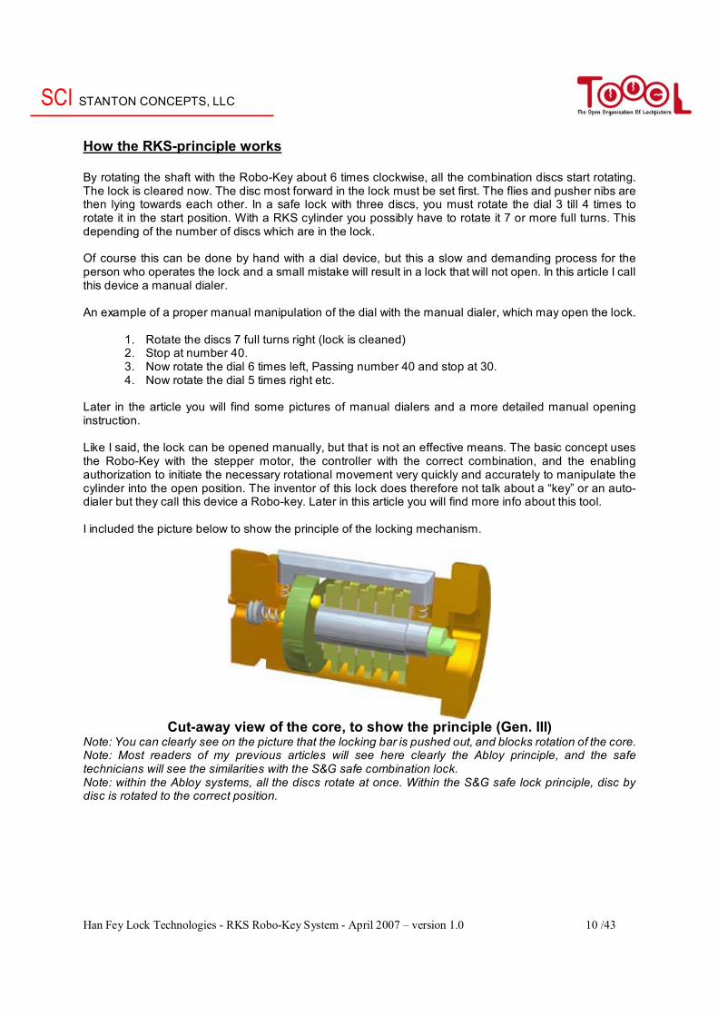
How the RKS-principle works By rotating the shaft with the Robo-Key about 6 times clockwise, all the combination discs start rotating. The lock is cleared now. The disc most forward in the lock must be set first. The flies and pusher nibs are then lying towards each other. In a safe lock with three discs, you must rotate the dial 3 till 4 times to rotate it in the start position. With a RKS cylinder you possibly have to rotate it 7 or more full turns. This depending of the number of discs which are in the lock. Of course this can be done by hand with a dial device, but this a slow and demanding process for the person who operates the lock and a small mistake will result in a lock that will not open. In this article I call this device a manual dialer. An example of a proper manual manipulation of the dial with the manual dialer, which may open the lock.
1. Rotate the discs 7 full turns right (lock is cleaned) 2. Stop at number 40. 3. Now rotate the dial 6 times left, Passing number 40 and stop at 30. 4. Now rotate the dial 5 times right etc.
Later in the article you will find some pictures of manual dialers and a more detailed manual opening instruction. Like I said, the lock can be opened manually, but that is not an effective means. The basic concept uses the Robo-Key with the stepper motor, the controller with the correct combination, and the enabling authorization to initiate the necessary rotational movement very quickly and accurately to manipulate the cylinder into the open position. The inventor of this lock does therefore not talk about a “key” or an auto-dialer but they call this device a Robo-key. Later in this article you will find more info about this tool. I included the picture below to show the principle of the locking mechanism.
Cut-away view of the core, to show the principle (Gen. III)
Note: You can clearly see on the picture that the locking bar is pushed out, and blocks rotation of the core. Note: Most readers of my previous articles will see here clearly the Abloy principle, and the safe technicians will see the similarities with the S&G safe combination lock. Note: within the Abloy systems, all the discs rotate at once. Within the S&G safe lock principle, disc by disc is rotated to the correct position.
SCI STANTON CONCEPTS, LLC
Han Fey Lock Technologies - RKS Robo-Key System - April 2007 – version 1.0 11 /43
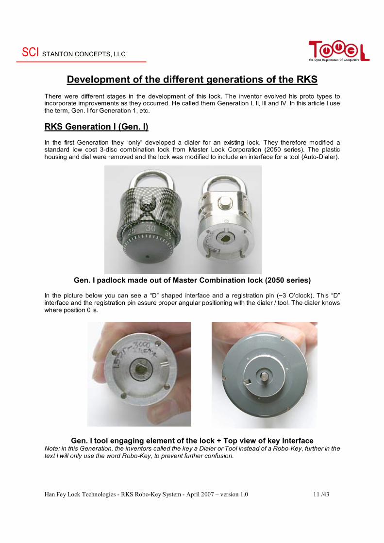
Development of the different generations of the RKS There were different stages in the development of this lock. The inventor evolved his proto types to incorporate improvements as they occurred. He called them Generation I, II, III and IV. In this article I use the term, Gen. I for Generation 1, etc. RKS Generation I (Gen. I) In the first Generation they “only” developed a dialer for an existing lock. They therefore modified a standard low cost 3-disc combination lock from Master Lock Corporation (2050 series). The plastic housing and dial were removed and the lock was modified to include an interface for a tool (Auto-Dialer).
Gen. I padlock made out of Master Combination lock (2050 series) In the picture below you can see a “D” shaped interface and a registration pin (~3 O’clock). This “D” interface and the registration pin assure proper angular positioning with the dialer / tool. The dialer knows where position 0 is.
Gen. I tool engaging element of the lock + Top view of key Interface Note: in this Generation, the inventors called the key a Dialer or Tool instead of a Robo-Key, further in the text I will only use the word Robo-Key, to prevent further confusion.
SCI STANTON CONCEPTS, LLC
Han Fey Lock Technologies - RKS Robo-Key System - April 2007 – version 1.0 12 /43
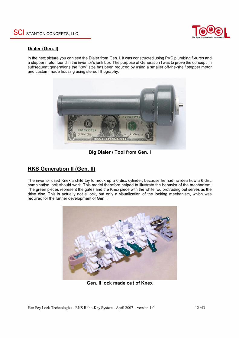
Dialer (Gen. I) In the next picture you can see the Dialer from Gen. I. It was constructed using PVC plumbing fixtures and a stepper motor found in the inventor’s junk box. The purpose of Generation I was to prove the concept. In subsequent generations the “key” size has been reduced by using a smaller off-the-shelf stepper motor and custom made housing using stereo lithography.
Big Dialer / Tool from Gen. I
RKS Generation II (Gen. II) The inventor used Knex a child toy to mock up a 6 disc cylinder, because he had no idea how a 6-disc combination lock should work. This model therefore helped to illustrate the behavior of the mechanism. The green pieces represent the gates and the Knex piece with the white rod protruding out serves as the drive disc. This is actually not a lock, but only a visualization of the locking mechanism, which was required for the further development of Gen II.
Gen. II lock made out of Knex
SCI STANTON CONCEPTS, LLC
Han Fey Lock Technologies - RKS Robo-Key System - April 2007 – version 1.0 13 /43
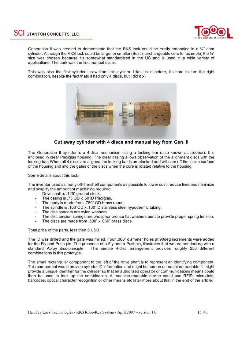
Generation II was created to demonstrate that the RKS lock could be easily embodied in a ¾” cam cylinder. Although the RKS lock could be larger or smaller (Best interchangeable core for example) the ¾” size was chosen because it’s somewhat standardized in the US and is used in a wide variety of applications. The cork was the first manual dialer. This was also the first cylinder I saw from this system. Like I said before, it’s hard to turn the right combination, despite the fact that6 it had only 4 discs, but I did it ;-).
Cut away cylinder with 4 discs and manual key from Gen. II
The Generation II cylinder is a 4-disc mechanism using a locking bar (also known as sidebar). It is enclosed in clear Plexiglas housing. The clear casing allows observation of the alignment discs with the locking bar. When all 4 discs are aligned the locking bar is un-blocked and will cam off the inside surface of the housing and into the gates of the discs when the core is rotated relative to the housing. Some details about this lock: The inventor used as many off-the-shelf components as possible to lower cost, reduce time and minimize and simplify the amount of machining required.
- Drive shaft is .125” ground stock. - The casing is .75 OD x .50 ID Plexiglas. - The body is made from .750” OD brass round. - The spindle is .166”OD x .130”ID stainless steel hypodermic tubing. - The disc spacers are nylon washers. - The disc tension springs are phosphor bronze flat washers bent to provide proper spring tension. - The discs are made from .500” x .060” brass discs.
Total price of the parts, less then 5 USD.
The ID was drilled and the gate was milled. Four .060” diameter holes at 90deg increments were added for the Fly and Push pin. The presence of a Fly and a Pushpin, illustrates that we are not dealing with a standard Abloy disc-principle. This simple 4-disc arrangement provides roughly 256 different combinations in this prototype. The small rectangular component to the left of the drive shaft is to represent an identifying component. This component would provide cylinder ID information and might be human or machine-readable. It might provide a unique identifier for the cylinder so that an authorized operator or communications means could then be used to look up the combination. A machine-readable device could use RFID, microdots, barcodes, optical character recognition or other means etc later more about that in the end of the article.
SCI STANTON CONCEPTS, LLC
Han Fey Lock Technologies - RKS Robo-Key System - April 2007 – version 1.0 14 /43
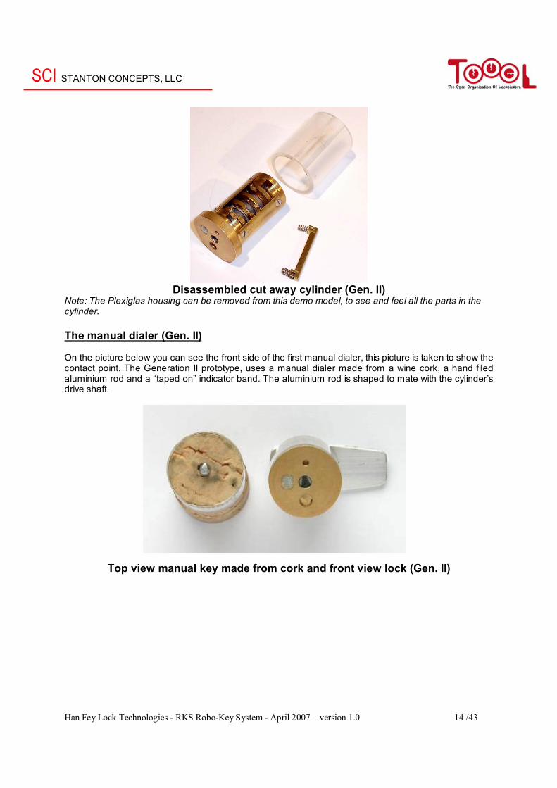
Disassembled cut away cylinder (Gen. II)
Note: The Plexiglas housing can be removed from this demo model, to see and feel all the parts in the cylinder. The manual dialer (Gen. II) On the picture below you can see the front side of the first manual dialer, this picture is taken to show the contact point. The Generation II prototype, uses a manual dialer made from a wine cork, a hand filed aluminium rod and a “taped on” indicator band. The aluminium rod is shaped to mate with the cylinder’s drive shaft.
Top view manual key made from cork and front view lock (Gen. II)
SCI STANTON CONCEPTS, LLC
Han Fey Lock Technologies - RKS Robo-Key System - April 2007 – version 1.0 15 /43
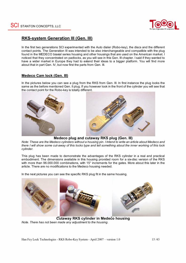
RKS-system Generation III (Gen. III) In the first two generations SCI experimented with the Auto dialer (Robo-key), the discs and the different contact points. The Generation III was intended to be also interchangeable and compatible with the plug found in the MEDECO biaxial series housing and other housings that are used on the American market. I noticed that they concentrated on padlocks, as you will see in this Gen. III chapter. I said if they wanted to have a wider market in Europe they had to extend their ideas to a bigger platform. You will find more about that in part Gen. IV, but now first the parts from Gen. III. Medeco Cam lock (Gen. III) In the pictures below you can see a plug from the RKS from Gen. III. In first instance the plug looks the same as the before mentioned Gen. II plug. If you however look in the front of the cylinder you will see that the contact point for the Robo-key is totally different.
Medeco plug and cutaway RKS plug (Gen. III)
Note: These are the Medeco cylinders without a housing pin. I Intend to write an article about Medeco and there I will show some cut-away of this locks type and tell something about the inner working of this lock cylinder. This plug has been made to demonstrate the advantages of the RKS cylinder in a real and practical embodiment. The dimensions available in this housing provided room for a six-disc version of the RKS with more than 96.000.000 combinations, with 15° increments for the gates. More about this later in the article. There are no modifications to the Medeco housing needed. In the next pictures you can see the specific RKS plug fit in the same housing.
Cutaway RKS cylinder in Medeco housing
Note. There has not been made any adjustment to the housing.
SCI STANTON CONCEPTS, LLC
Han Fey Lock Technologies - RKS Robo-Key System - April 2007 – version 1.0 16 /43
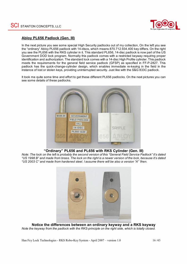
Abloy PL656 Padlock (Gen. III) In the next picture you see some special High Security padlocks out of my collection, On the left you see the “ordinary” Abloy PL656 padlock with 14-discs, which means 870.712.934.400 key differs. On the right you see the PL656 with the RKS cylinder in it. This standard PL656, 14-disc padlock is now part of the US Government DOD lock program. Normally this padlock comes with a restricted keyway requiring proper identification and authorization. The standard lock comes with a 14-disc High Profile cylinder. This padlock meets the requirements for the general field service padlock (GFSP) as specified in FF-P-2827. This padlock has the quick-change-cylinder design, which enables immediate re-keying in the field in the instance of lost or stolen keys, providing uninterrupted security. Just like with the S&G 833C padlock. It took me quite some time and effort to get these different PL656 padlocks. On the next pictures you can see some details of these padlocks.
“Ordinary” PL656 and PL656 with RKS Cylinder (Gen. III)
Note: The lock on the left is probably the second version of this “General Field Service Padlock” it’s dated “US 1998 B” and made from brass. The lock on the right is a newer version of the lock, because it’s dated “US 2003 C” and made from hardened steel. I assume there will be also a version “A” ’then.
Notice the differences between an ordinary keyway and a RKS keyway
Note the keyway from the padlock with the RKS-principle on the right side, which is totally closed.
SCI STANTON CONCEPTS, LLC
Han Fey Lock Technologies - RKS Robo-Key System - April 2007 – version 1.0 17 /43
PL656 with removed cores
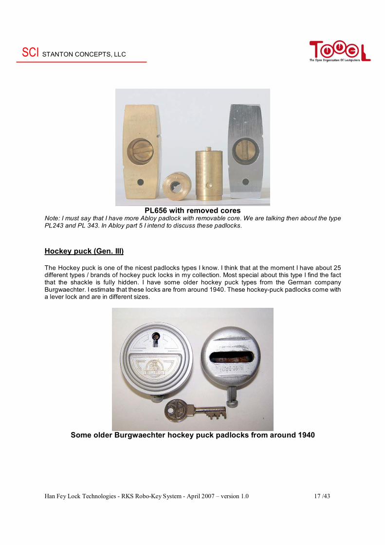
Note: I must say that I have more Abloy padlock with removable core. We are talking then about the type PL243 and PL 343. In Abloy part 5 I intend to discuss these padlocks. Hockey puck (Gen. III) The Hockey puck is one of the nicest padlocks types I know. I think that at the moment I have about 25 different types / brands of hockey puck locks in my collection. Most special about this type I find the fact that the shackle is fully hidden. I have some older hockey puck types from the German company Burgwaechter. I estimate that these locks are from around 1940. These hockey-puck padlocks come with a lever lock and are in different sizes.
Some older Burgwaechter hockey puck padlocks from around 1940
SCI STANTON CONCEPTS, LLC
Han Fey Lock Technologies - RKS Robo-Key System - April 2007 – version 1.0 18 /43
The modern hockey puck style lock has some very positive aspects above the older types of hockey pucks, these advantages are:
- Standardized dimensions shackle size and location (there are some slight variations between manufactures) - Available from a large number of manufacturers - Wide variety of cylinder types; low to high security - Good security at low cost
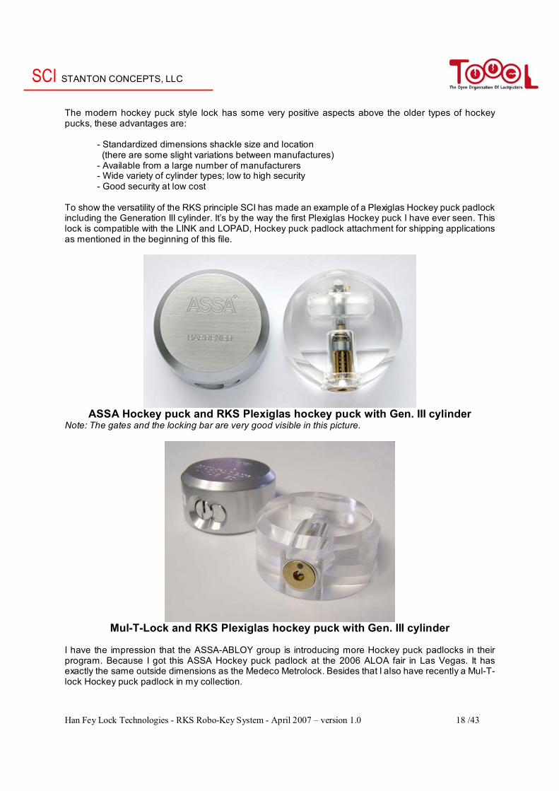
To show the versatility of the RKS principle SCI has made an example of a Plexiglas Hockey puck padlock including the Generation III cylinder. It’s by the way the first Plexiglas Hockey puck I have ever seen. This lock is compatible with the LINK and LOPAD, Hockey puck padlock attachment for shipping applications as mentioned in the beginning of this file.
ASSA Hockey puck and RKS Plexiglas hockey puck with Gen. III cylinder
Note: The gates and the locking bar are very good visible in this picture.
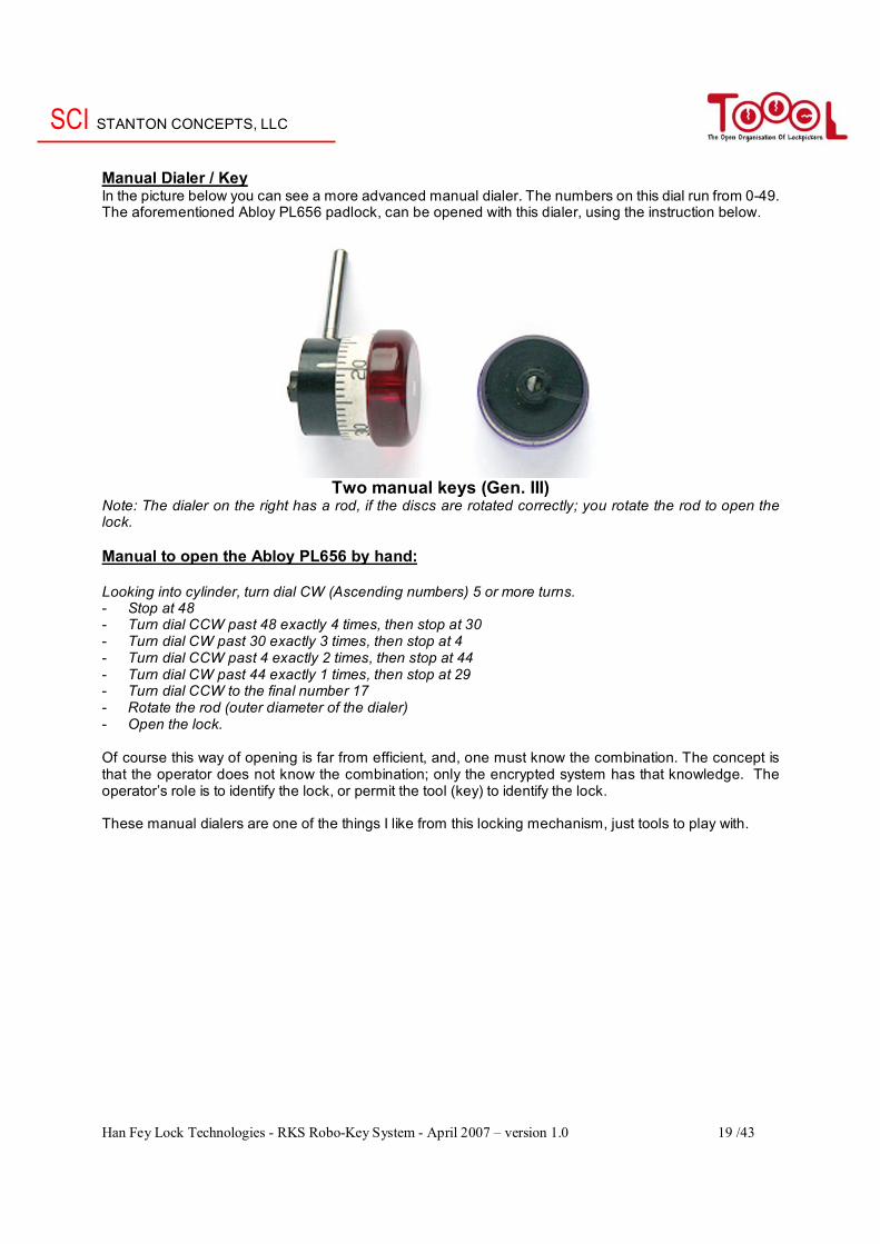
Mul-T-Lock and RKS Plexiglas hockey puck with Gen. III cylinder
I have the impression that the ASSA-ABLOY group is introducing more Hockey puck padlocks in their program. Because I got this ASSA Hockey puck padlock at the 2006 ALOA fair in Las Vegas. It has exactly the same outside dimensions as the Medeco Metrolock. Besides that I also have recently a Mul-T-lock Hockey puck padlock in my collection.
SCI STANTON CONCEPTS, LLC
Han Fey Lock Technologies - RKS Robo-Key System - April 2007 – version 1.0 19 /43
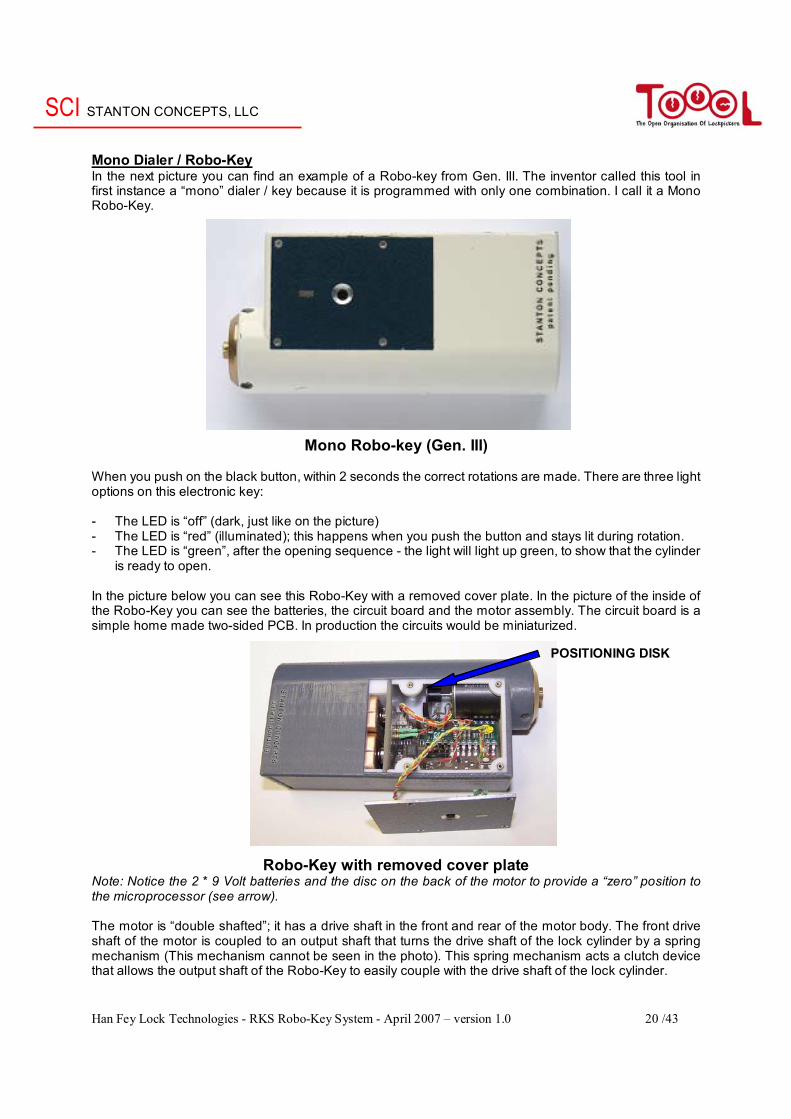
Manual Dialer / Key In the picture below you can see a more advanced manual dialer. The numbers on this dial run from 0-49. The aforementioned Abloy PL656 padlock, can be opened with this dialer, using the instruction below.
Two manual keys (Gen. III)
Note: The dialer on the right has a rod, if the discs are rotated correctly; you rotate the rod to open the lock. Manual to open the Abloy PL656 by hand: Looking into cylinder, turn dial CW (Ascending numbers) 5 or more turns. - Stop at 48 - Turn dial CCW past 48 exactly 4 times, then stop at 30 - Turn dial CW past 30 exactly 3 times, then stop at 4 - Turn dial CCW past 4 exactly 2 times, then stop at 44 - Turn dial CW past 44 exactly 1 times, then stop at 29 - Turn dial CCW to the final number 17 - Rotate the rod (outer diameter of the dialer) - Open the lock. Of course this way of opening is far from efficient, and, one must know the combination. The concept is that the operator does not know the combination; only the encrypted system has that knowledge. The operator’s role is to identify the lock, or permit the tool (key) to identify the lock. These manual dialers are one of the things I like from this locking mechanism, just tools to play with.
SCI STANTON CONCEPTS, LLC
Han Fey Lock Technologies - RKS Robo-Key System - April 2007 – version 1.0 20 /43
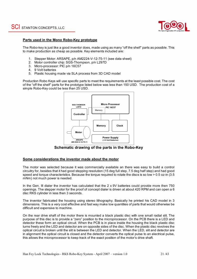
Mono Dialer / Robo-Key In the next picture you can find an example of a Robo-key from Gen. III. The inventor called this tool in first instance a “mono” dialer / key because it is programmed with only one combination. I call it a Mono Robo-Key.
Mono Robo-key (Gen. III) When you push on the black button, within 2 seconds the correct rotations are made. There are three light options on this electronic key: - The LED is “off” (dark, just like on the picture) - The LED is “red” (illuminated); this happens when you push the button and stays lit during rotation. - The LED is “green”, after the opening sequence - the light will light up green, to show that the cylinder
is ready to open. In the picture below you can see this Robo-Key with a removed cover plate. In the picture of the inside of the Robo-Key you can see the batteries, the circuit board and the motor assembly. The circuit board is a simple home made two-sided PCB. In production the circuits would be miniaturized.
Robo-Key with removed cover plate Note: Notice the 2 * 9 Volt batteries and the disc on the back of the motor to provide a “zero” position to the microprocessor (see arrow). The motor is “double shafted”; it has a drive shaft in the front and rear of the motor body. The front drive shaft of the motor is coupled to an output shaft that turns the drive shaft of the lock cylinder by a spring mechanism (This mechanism cannot be seen in the photo). This spring mechanism acts a clutch device that allows the output shaft of the Robo-Key to easily couple with the drive shaft of the lock cylinder.
POSITIONING DISK
SCI STANTON CONCEPTS, LLC
Han Fey Lock Technologies - RKS Robo-Key System - April 2007 – version 1.0 21 /43
Parts used in the Mono Robo-Key prototype The Robo-key is just like a good inventor does, made using as many “off the shelf” parts as possible. This to make production as cheap as possible. Key elements included are:
1. Stepper Motor: ARSAPE, p/n AM2224-V-12-75-11 (see data sheet) 2. Motor controller chip: SGS-Thompson, p/n L297D 3. Micro-processor: PIC p/n 16C57 4. 9 Volt batteries 5. Plastic housing made via SLA process from 3D CAD model
Production Robo Keys will use specific parts to meet the requirements at the least possible cost. The cost of the “off the shelf” parts for the prototype listed below was less than 150 USD. The production cost of a simple Robo-Key could be less than 25 USD.
Schematic drawing of the parts in the Robo-Key Some considerations the inventor made about the motor The motor was selected because it was commercially available an there was easy to build a control circuitry for, besides that it had good stepping resolution (15 deg full step, 7.5 deg half step) and had good speed and torque characteristics. Because the torque required to rotate the discs is so low > 0.5 oz-in (3.5 mNm) not much power is needed. In the Gen. III dialer the inventor has calculated that the 2 x 9V batteries could provide more then 750 openings. The stepper motor for the proof of concept dialer is driven at about 420 RPM and can open a 6 disc RKS cylinder in less then 3 seconds. The inventor fabricated the housing using stereo lithography. Basically he printed his CAD model in 3 dimensions. This is a very cost effective and fast way make low quantities of parts that would otherwise be difficult and expensive to machine. On the rear drive shaft of the motor there is mounted a black plastic disc with one small radial slit. The purpose of this disc is to provide a “zero” position to the microprocessor. On the PCB there is a LED and detector these form an optical circuit. When the PCB is in place inside the housing the black plastic disc turns freely and the LED and detector are on opposite sides of the disc. When the plastic disc revolves the optical circuit is broken until the slit is between the LED and detector. When the LED, slit and detector are in alignment the optical circuit is closed and the detector converts the optical pulse to an electrical pulse, this allows the microprocessor to keep track of the exact position of the motor’s drive shaft.
Micro Processor
Memory
Controller
Power Supply( 2 9 Volt Batteries)
Clock
Memory
Motor
PIC 16C57
ARSAPEAM 2224-V-12-75-11
SGS-THOMSONL297D
SCI STANTON CONCEPTS, LLC
Han Fey Lock Technologies - RKS Robo-Key System - April 2007 – version 1.0 22 /43
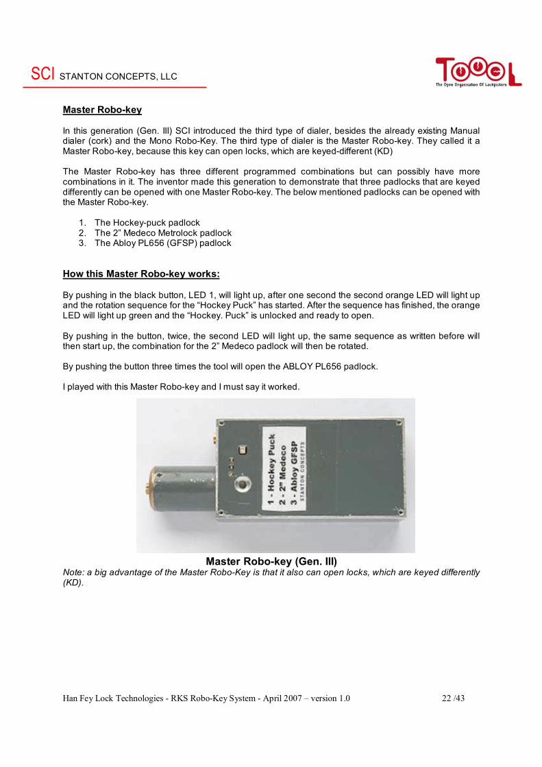
Master Robo-key In this generation (Gen. III) SCI introduced the third type of dialer, besides the already existing Manual dialer (cork) and the Mono Robo-Key. The third type of dialer is the Master Robo-key. They called it a Master Robo-key, because this key can open locks, which are keyed-different (KD) The Master Robo-key has three different programmed combinations but can possibly have more combinations in it. The inventor made this generation to demonstrate that three padlocks that are keyed differently can be opened with one Master Robo-key. The below mentioned padlocks can be opened with the Master Robo-key.
1. The Hockey-puck padlock 2. The 2” Medeco Metrolock padlock 3. The Abloy PL656 (GFSP) padlock
How this Master Robo-key works: By pushing in the black button, LED 1, will light up, after one second the second orange LED will light up and the rotation sequence for the “Hockey Puck” has started. After the sequence has finished, the orange LED will light up green and the “Hockey. Puck” is unlocked and ready to open. By pushing in the button, twice, the second LED will light up, the same sequence as written before will then start up, the combination for the 2” Medeco padlock will then be rotated. By pushing the button three times the tool will open the ABLOY PL656 padlock. I played with this Master Robo-key and I must say it worked.
Master Robo-key (Gen. III) Note: a big advantage of the Master Robo-Key is that it also can open locks, which are keyed differently (KD).
SCI STANTON CONCEPTS, LLC
Han Fey Lock Technologies - RKS Robo-Key System - April 2007 – version 1.0 23 /43
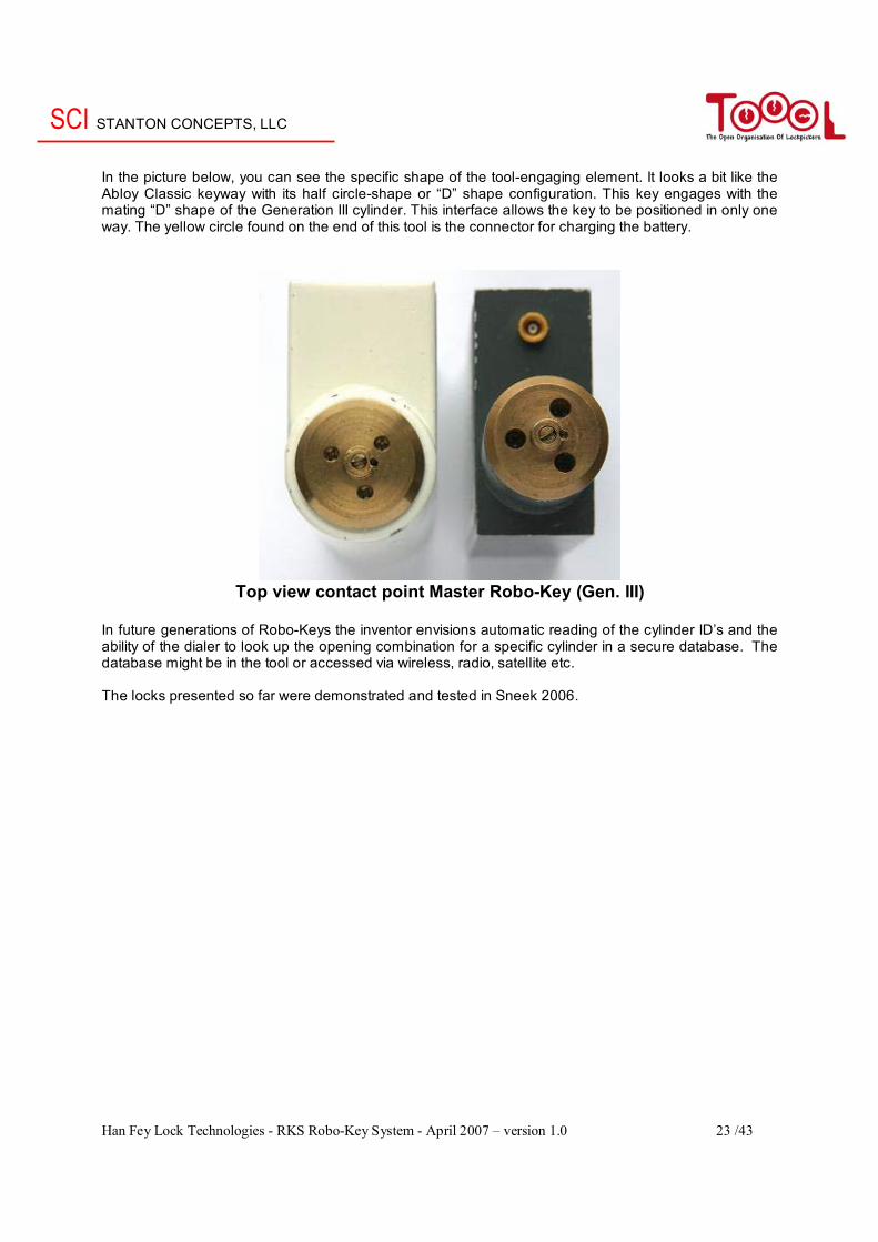
In the picture below, you can see the specific shape of the tool-engaging element. It looks a bit like the Abloy Classic keyway with its half circle-shape or “D” shape configuration. This key engages with the mating “D” shape of the Generation III cylinder. This interface allows the key to be positioned in only one way. The yellow circle found on the end of this tool is the connector for charging the battery.
Top view contact point Master Robo-Key (Gen. III) In future generations of Robo-Keys the inventor envisions automatic reading of the cylinder ID’s and the ability of the dialer to look up the opening combination for a specific cylinder in a secure database. The database might be in the tool or accessed via wireless, radio, satellite etc. The locks presented so far were demonstrated and tested in Sneek 2006.

SCI STANTON CONCEPTS, LLC
Han Fey Lock Technologies - RKS Robo-Key System - April 2007 – version 1.0 24 /43
RKS Generation IV In November 2006 there was the Dutch Open in Sneek from Toool. I invited the inventors to come and John Loughlin was so kind to introduce his lock there and to give a presentation of the RKS. Lock pickers from all over the world (United States, United Kingdom, France, Germany, etc were invited to manipulate and comment on this new lock concept. In this chapter you can see many improvement, as a result of the visit in Sneek and the discussions with a lot of other people all over the world about how to improve the concept. Some goals in Gen IV were:
- Improve the Robo-key interface / contact point - Make the lock compatible with European locks (Euro profile, Scandinavian Oval, etc.) - Make the lock more easily re-combinated - Scramble the discs after opening the lock - Make the lock more robust (monkey proof)
In my opinion many of these goals were achieved, as you will see later in the article.
Front view Gen. III, Gen. IV and a picture of a Gen. IV cylinder The changes in Generation IV include increasing the tool interface diameter, increasing the lead in chamfer and moving the alignment pin to the 3 o’clock position. These changes make the tool insertion easier. If you have a close look on this picture you will see these chances.
Some RKS Gen. IV cylinders
SCI STANTON CONCEPTS, LLC
Han Fey Lock Technologies - RKS Robo-Key System - April 2007 – version 1.0 25 /43
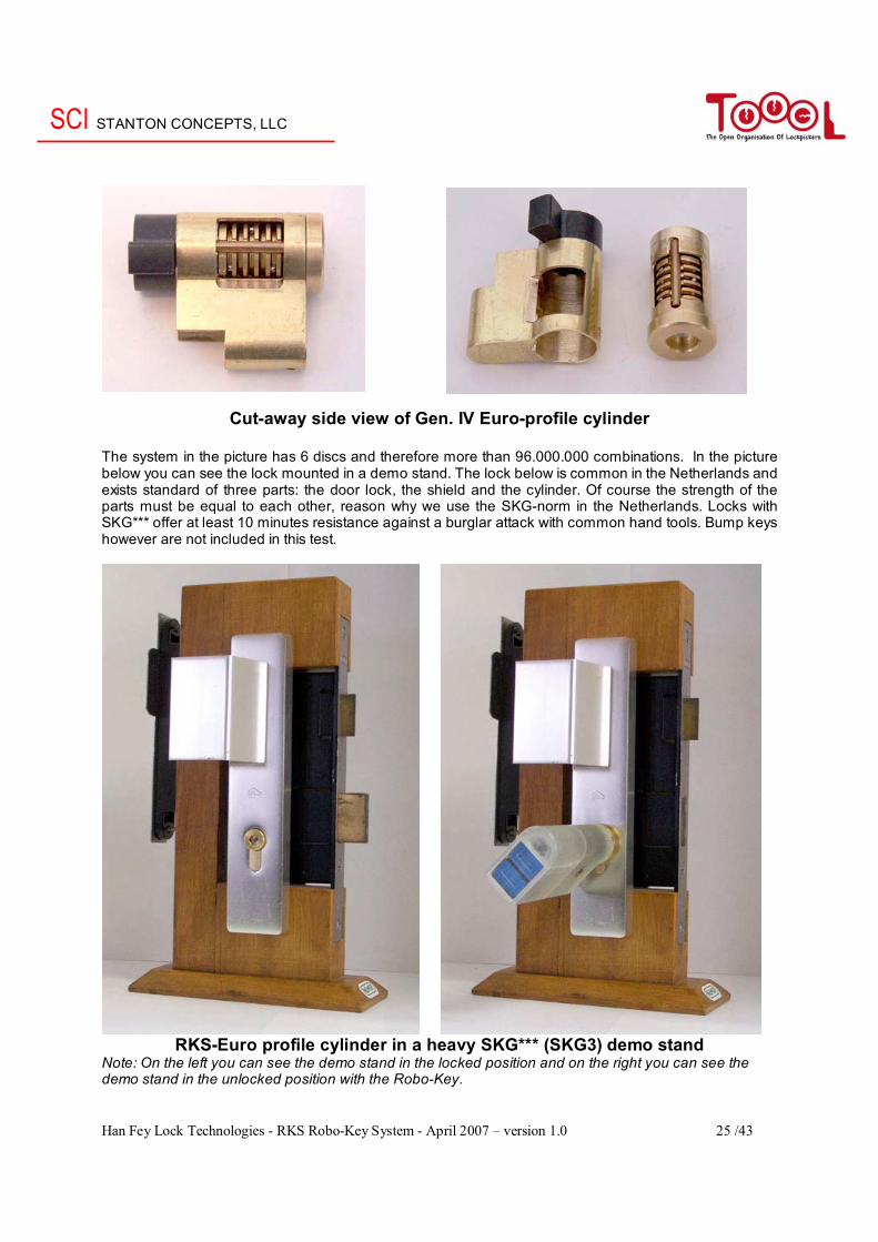
Cut-away side view of Gen. IV Euro-profile cylinder The system in the picture has 6 discs and therefore more than 96.000.000 combinations. In the picture below you can see the lock mounted in a demo stand. The lock below is common in the Netherlands and exists standard of three parts: the door lock, the shield and the cylinder. Of course the strength of the parts must be equal to each other, reason why we use the SKG-norm in the Netherlands. Locks with SKG*** offer at least 10 minutes resistance against a burglar attack with common hand tools. Bump keys however are not included in this test.
RKS-Euro profile cylinder in a heavy SKG*** (SKG3) demo stand
Note: On the left you can see the demo stand in the locked position and on the right you can see the demo stand in the unlocked position with the Robo-Key.
SCI STANTON CONCEPTS, LLC
Han Fey Lock Technologies - RKS Robo-Key System - April 2007 – version 1.0 26 /43
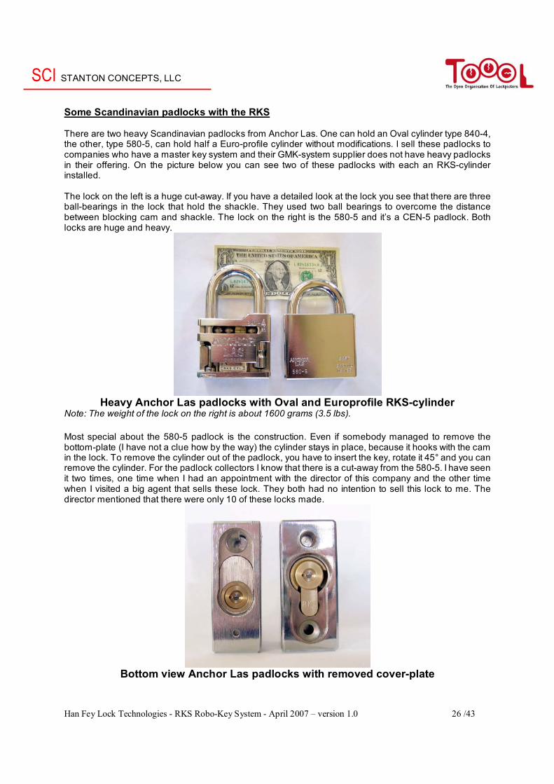
Some Scandinavian padlocks with the RKS There are two heavy Scandinavian padlocks from Anchor Las. One can hold an Oval cylinder type 840-4, the other, type 580-5, can hold half a Euro-profile cylinder without modifications. I sell these padlocks to companies who have a master key system and their GMK-system supplier does not have heavy padlocks in their offering. On the picture below you can see two of these padlocks with each an RKS-cylinder installed. The lock on the left is a huge cut-away. If you have a detailed look at the lock you see that there are three ball-bearings in the lock that hold the shackle. They used two ball bearings to overcome the distance between blocking cam and shackle. The lock on the right is the 580-5 and it’s a CEN-5 padlock. Both locks are huge and heavy.
Heavy Anchor Las padlocks with Oval and Europrofile RKS-cylinder
Note: The weight of the lock on the right is about 1600 grams (3.5 lbs). Most special about the 580-5 padlock is the construction. Even if somebody managed to remove the bottom-plate (I have not a clue how by the way) the cylinder stays in place, because it hooks with the cam in the lock. To remove the cylinder out of the padlock, you have to insert the key, rotate it 45° and you can remove the cylinder. For the padlock collectors I know that there is a cut-away from the 580-5. I have seen it two times, one time when I had an appointment with the director of this company and the other time when I visited a big agent that sells these lock. They both had no intention to sell this lock to me. The director mentioned that there were only 10 of these locks made.
Bottom view Anchor Las padlocks with removed cover-plate
SCI STANTON CONCEPTS, LLC
Han Fey Lock Technologies - RKS Robo-Key System - April 2007 – version 1.0 27 /43
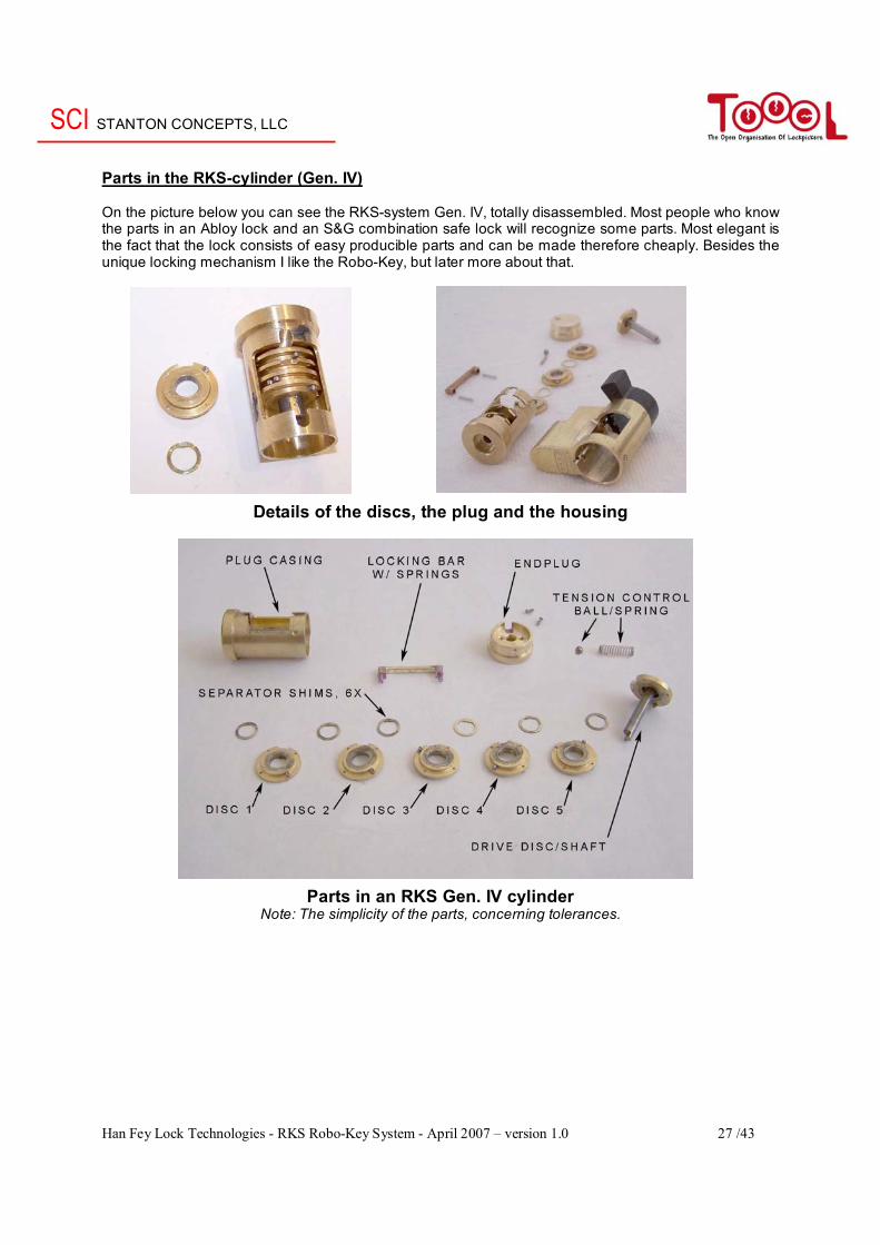
Parts in the RKS-cylinder (Gen. IV) On the picture below you can see the RKS-system Gen. IV, totally disassembled. Most people who know the parts in an Abloy lock and an S&G combination safe lock will recognize some parts. Most elegant is the fact that the lock consists of easy producible parts and can be made therefore cheaply. Besides the unique locking mechanism I like the Robo-Key, but later more about that.
Details of the discs, the plug and the housing
Parts in an RKS Gen. IV cylinder Note: The simplicity of the parts, concerning tolerances.
SCI STANTON CONCEPTS, LLC
Han Fey Lock Technologies - RKS Robo-Key System - April 2007 – version 1.0 28 /43
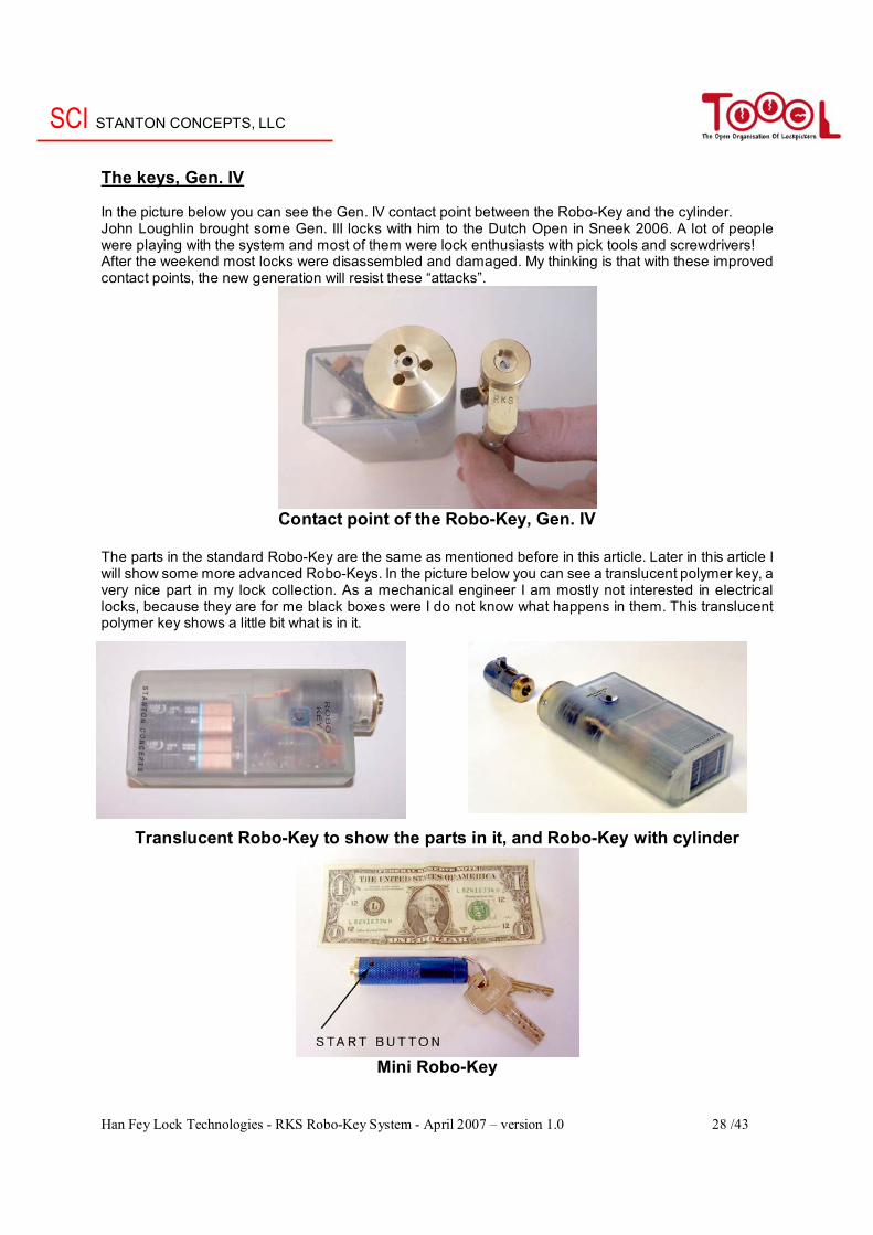
The keys, Gen. IV In the picture below you can see the Gen. IV contact point between the Robo-Key and the cylinder. John Loughlin brought some Gen. III locks with him to the Dutch Open in Sneek 2006. A lot of people were playing with the system and most of them were lock enthusiasts with pick tools and screwdrivers! After the weekend most locks were disassembled and damaged. My thinking is that with these improved contact points, the new generation will resist these “attacks”.
Contact point of the Robo-Key, Gen. IV
The parts in the standard Robo-Key are the same as mentioned before in this article. Later in this article I will show some more advanced Robo-Keys. In the picture below you can see a translucent polymer key, a very nice part in my lock collection. As a mechanical engineer I am mostly not interested in electrical locks, because they are for me black boxes were I do not know what happens in them. This translucent polymer key shows a little bit what is in it.
Translucent Robo-Key to show the parts in it, and Robo-Key with cylinder
Mini Robo-Key
SCI STANTON CONCEPTS, LLC
Han Fey Lock Technologies - RKS Robo-Key System - April 2007 – version 1.0 29 /43
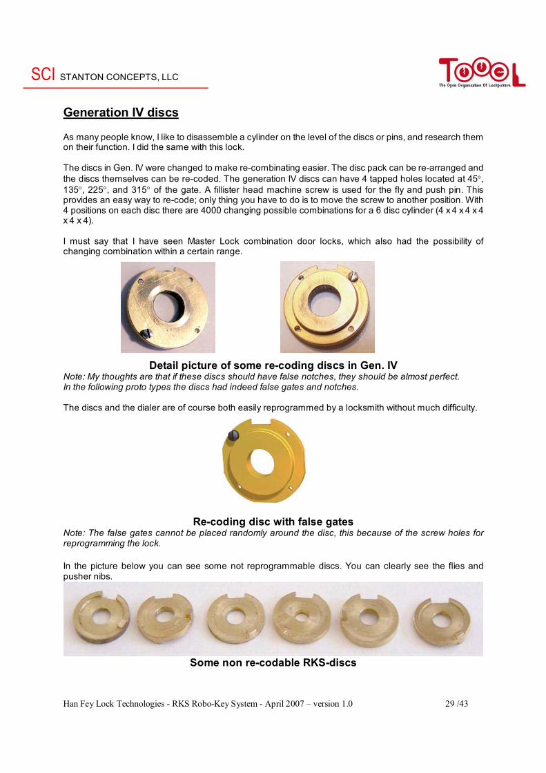
Generation IV discs As many people know, I like to disassemble a cylinder on the level of the discs or pins, and research them on their function. I did the same with this lock. The discs in Gen. IV were changed to make re-combinating easier. The disc pack can be re-arranged and the discs themselves can be re-coded. The generation IV discs can have 4 tapped holes located at 45°, 135°, 225°, and 315° of the gate. A fillister head machine screw is used for the fly and push pin. This provides an easy way to re-code; only thing you have to do is to move the screw to another position. With 4 positions on each disc there are 4000 changing possible combinations for a 6 disc cylinder (4 x 4 x 4 x 4 x 4 x 4). I must say that I have seen Master Lock combination door locks, which also had the possibility of changing combination within a certain range.
Detail picture of some re-coding discs in Gen. IV Note: My thoughts are that if these discs should have false notches, they should be almost perfect. In the following proto types the discs had indeed false gates and notches. The discs and the dialer are of course both easily reprogrammed by a locksmith without much difficulty.
Re-coding disc with false gates Note: The false gates cannot be placed randomly around the disc, this because of the screw holes for reprogramming the lock. In the picture below you can see some not reprogrammable discs. You can clearly see the flies and pusher nibs.
Some non re-codable RKS-discs
SCI STANTON CONCEPTS, LLC
Han Fey Lock Technologies - RKS Robo-Key System - April 2007 – version 1.0 30 /43
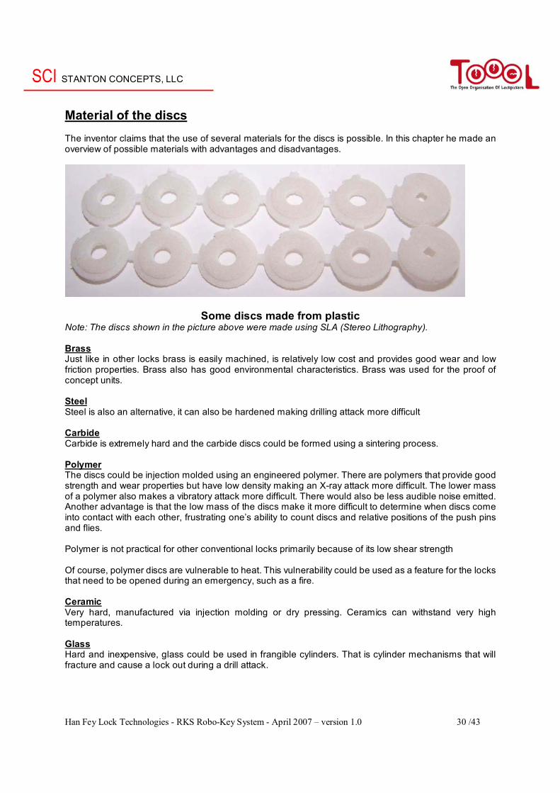
Material of the discs The inventor claims that the use of several materials for the discs is possible. In this chapter he made an overview of possible materials with advantages and disadvantages.
Some discs made from plastic Note: The discs shown in the picture above were made using SLA (Stereo Lithography). Brass Just like in other locks brass is easily machined, is relatively low cost and provides good wear and low friction properties. Brass also has good environmental characteristics. Brass was used for the proof of concept units. Steel Steel is also an alternative, it can also be hardened making drilling attack more difficult Carbide Carbide is extremely hard and the carbide discs could be formed using a sintering process. Polymer The discs could be injection molded using an engineered polymer. There are polymers that provide good strength and wear properties but have low density making an X-ray attack more difficult. The lower mass of a polymer also makes a vibratory attack more difficult. There would also be less audible noise emitted. Another advantage is that the low mass of the discs make it more difficult to determine when discs come into contact with each other, frustrating one’s ability to count discs and relative positions of the push pins and flies. Polymer is not practical for other conventional locks primarily because of its low shear strength Of course, polymer discs are vulnerable to heat. This vulnerability could be used as a feature for the locks that need to be opened during an emergency, such as a fire. Ceramic Very hard, manufactured via injection molding or dry pressing. Ceramics can withstand very high temperatures. Glass Hard and inexpensive, glass could be used in frangible cylinders. That is cylinder mechanisms that will fracture and cause a lock out during a drill attack.
SCI STANTON CONCEPTS, LLC
Han Fey Lock Technologies - RKS Robo-Key System - April 2007 – version 1.0 31 /43
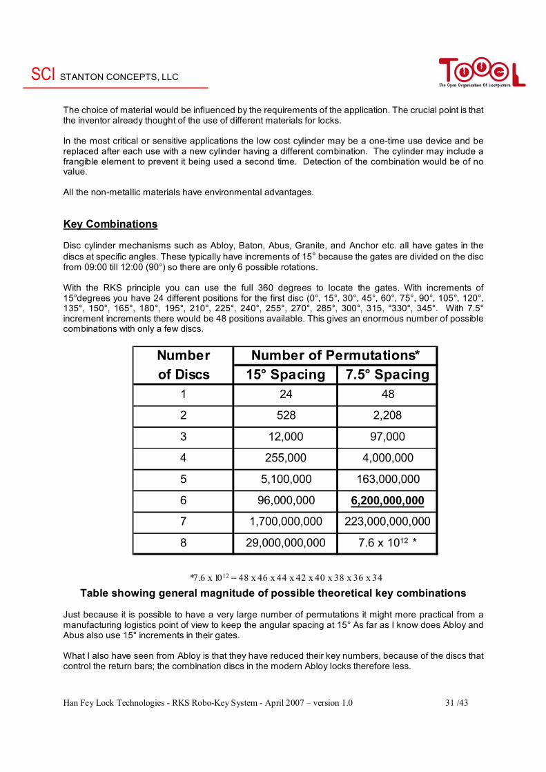
The choice of material would be influenced by the requirements of the application. The crucial point is that the inventor already thought of the use of different materials for locks. In the most critical or sensitive applications the low cost cylinder may be a one-time use device and be replaced after each use with a new cylinder having a different combination. The cylinder may include a frangible element to prevent it being used a second time. Detection of the combination would be of no value. All the non-metallic materials have environmental advantages. Key Combinations Disc cylinder mechanisms such as Abloy, Baton, Abus, Granite, and Anchor etc. all have gates in the discs at specific angles. These typically have increments of 15° because the gates are divided on the disc from 09:00 till 12:00 (90°) so there are only 6 possible rotations. With the RKS principle you can use the full 360 degrees to locate the gates. With increments of 15°degrees you have 24 different positions for the first disc (0°, 15°, 30°, 45°, 60°, 75°, 90°, 105°, 120°, 135°, 150°, 165°, 180°, 195°, 210°, 225°, 240°, 255°, 270°, 285°, 300°, 315, °330°, 345°. With 7.5° increment increments there would be 48 positions available. This gives an enormous number of possible combinations with only a few discs.
Table showing general magnitude of possible theoretical key combinations Just because it is possible to have a very large number of permutations it might more practical from a manufacturing logistics point of view to keep the angular spacing at 15° As far as I know does Abloy and Abus also use 15° increments in their gates. What I also have seen from Abloy is that they have reduced their key numbers, because of the discs that control the return bars; the combination discs in the modern Abloy locks therefore less.
Numberof Discs 15° Spacing 7.5° Spacing
1 24 48
2 528 2,208
3 12,000 97,000
4 255,000 4,000,000
5 5,100,000 163,000,000
6 96,000,000 6,200,000,000
7 1,700,000,000 223,000,000,000
8 29,000,000,000 7.6 x 10¹² *
*7.6 x 1012 = 48 x 46 x 44 x 42 x 40 x 38 x 36 x 34
Number of Permutations*
SCI STANTON CONCEPTS, LLC
Han Fey Lock Technologies - RKS Robo-Key System - April 2007 – version 1.0 32 /43
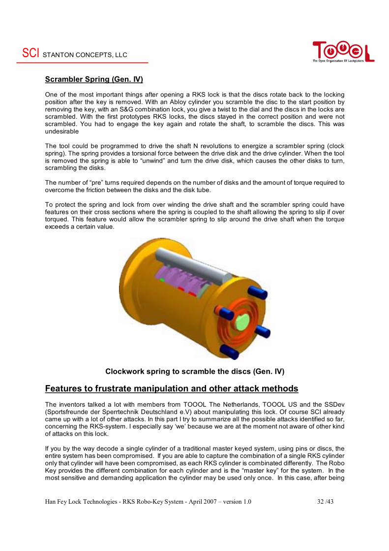
Scrambler Spring (Gen. IV) One of the most important things after opening a RKS lock is that the discs rotate back to the locking position after the key is removed. With an Abloy cylinder you scramble the disc to the start position by removing the key, with an S&G combination lock, you give a twist to the dial and the discs in the locks are scrambled. With the first prototypes RKS locks, the discs stayed in the correct position and were not scrambled. You had to engage the key again and rotate the shaft, to scramble the discs. This was undesirable The tool could be programmed to drive the shaft N revolutions to energize a scrambler spring (clock spring). The spring provides a torsional force between the drive disk and the drive cylinder. When the tool is removed the spring is able to “unwind” and turn the drive disk, which causes the other disks to turn, scrambling the disks. The number of “pre” turns required depends on the number of disks and the amount of torque required to overcome the friction between the disks and the disk tube. To protect the spring and lock from over winding the drive shaft and the scrambler spring could have features on their cross sections where the spring is coupled to the shaft allowing the spring to slip if over torqued. This feature would allow the scrambler spring to slip around the drive shaft when the torque exceeds a certain value.
Clockwork spring to scramble the discs (Gen. IV) Features to frustrate manipulation and other attack methods The inventors talked a lot with members from TOOOL The Netherlands, TOOOL US and the SSDev (Sportsfreunde der Sperrtechnik Deutschland e.V) about manipulating this lock. Of course SCI already came up with a lot of other attacks. In this part I try to summarize all the possible attacks identified so far, concerning the RKS-system. I especially say ‘we’ because we are at the moment not aware of other kind of attacks on this lock. If you by the way decode a single cylinder of a traditional master keyed system, using pins or discs, the entire system has been compromised. If you are able to capture the combination of a single RKS cylinder only that cylinder will have been compromised, as each RKS cylinder is combinated differently. The Robo Key provides the different combination for each cylinder and is the “master key” for the system. In the most sensitive and demanding application the cylinder may be used only once. In this case, after being
SCI STANTON CONCEPTS, LLC
Han Fey Lock Technologies - RKS Robo-Key System - April 2007 – version 1.0 33 /43
open, the original cylinder would be removed and a new unused cylinder installed. The used cylinder may be recycled within the system or destroyed. It may be possible to include a frangible element in the cylinder that ruptures when it functions and may never be used a second time, preventing accidental reuse. Safe lock manipulation One common method to manipulate lock mechanisms is by exploiting the manufacturing tolerances. Because no two disks will ever be exactly the same size, a person with the proper skills could theoretically “feel” when a gate is aligned with the side bar by applying a light torque the drive cylinder while turning the drive shaft. The disk with the largest diameter would drag along the side bar until the side bar drops into the gate. A person of sufficient skill might be able to determine the disk’s gate position. He would then try to determine the disk number and the gate position of the disk with the next largest diameter and so on. To make this method of manipulation more difficult a soft elastic bushing could be placed between the disk and the disk spindle. The bushing would absorb the pressure applied by the side bar obscuring the slight dimensional variations of the disks. Another feature that could be employed to frustrate manipulation is to have false gates on the drive wheel. The drive wheel would have a larger diameter than the other disk(s). The bottom of the false gate would correspond to the outside diameter of the other disk(s). When the locking bar is cammed in to the gate the drive wheel is prevented from turning. The RKS cylinders could also be equipped with a variable number of disks from unit to unit so the manipulator would not know how many disks he is dealing with. Emissions X-Ray One well known method of attack is to X-Ray the cylinder to visualize the coding. In addition to shielding high and low density materials could be selected for specific RKS components to diminish the efficacy of this attack. Audio It might be possible to acoustically ‘impression’ the opening combination by surreptitiously capturing the acoustic signature with a sensitive recording device. Although this is an area where I do not know all tools that are currently available or might be available in the future some basic inherent features of the RKS could make this difficult in addition to other counter measures that could be employed. Some inherent aspects of the cylinder are the very low mass of the discs and the very low torque required to drive them. Additional counter measures could include coating the discs with a compliant material, having the dialer emit random noise to mask the acoustic signature of the disc alignment. EM Emissions The technology to listen to the tool via EM (Electro Magnetic) emissions is well known and continuously evolving. The best counter measure for this attack is applied engineering of the dialer to shield emissions and to possibly emit false signals. Capturing the Motion of the Robo-key Video capture of the movement; this is impractical with today’s technology. The motor for the Robo-key could be driven at least 420 RPM (Revolutions Per Minute) which would open a 6 disc OMNI cylinder in under 3 seconds. This means that 420 RPM equals 7 RPS (Revolutions Per Second); 7 RPS X 48 possible positions per revolution equal 336 positions per second. Standard video cameras capture motion at about 30 frames per second which means that capturing the opening motion of an Robo-key via video capture with today’s standard technology is not possible. Capturing the motion by other means such as an optical encoder et cetera is possible. In fact this is probably the attack the RKS system is most vulnerable to. To mitigate this mode of attack the Robo-key could be layered with additional layers of security including access control, biometrics etc.
SCI STANTON CONCEPTS, LLC
Han Fey Lock Technologies - RKS Robo-Key System - April 2007 – version 1.0 34 /43
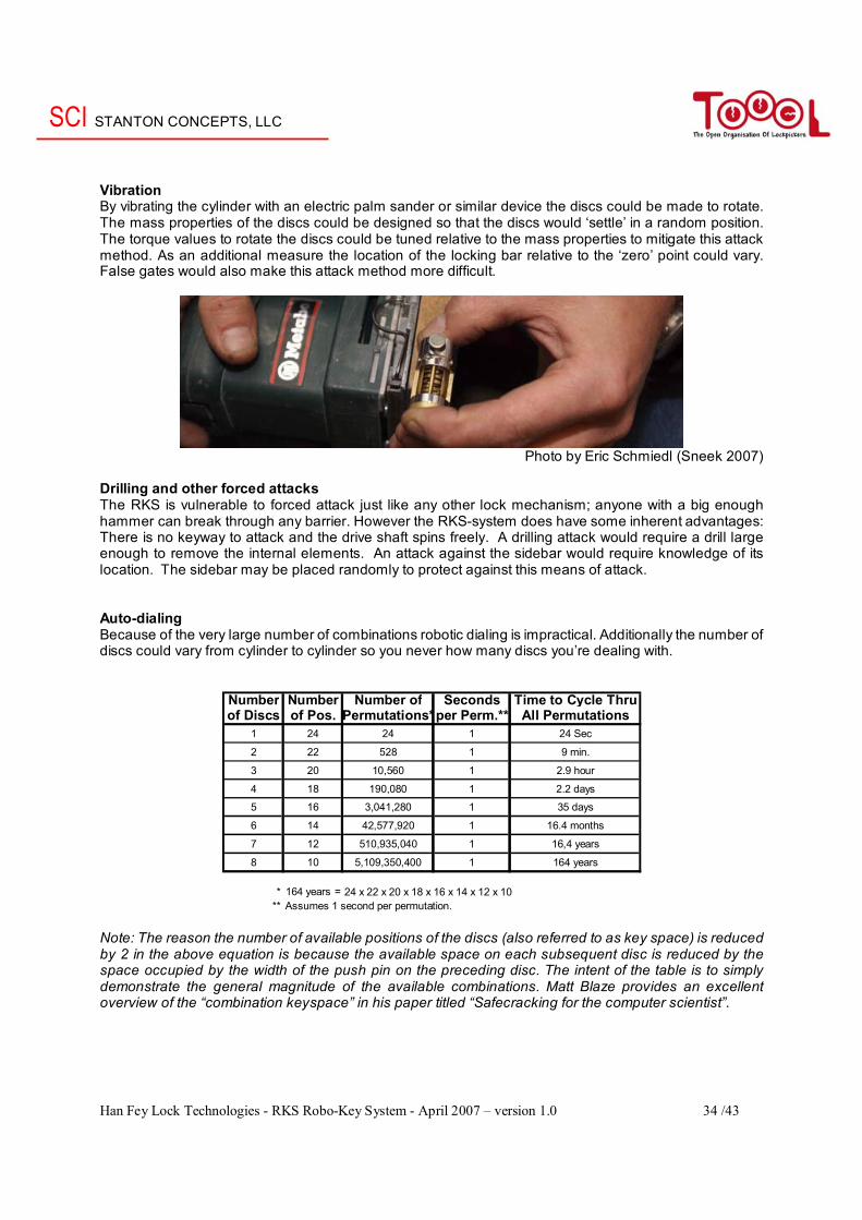
Vibration By vibrating the cylinder with an electric palm sander or similar device the discs could be made to rotate. The mass properties of the discs could be designed so that the discs would ‘settle’ in a random position. The torque values to rotate the discs could be tuned relative to the mass properties to mitigate this attack method. As an additional measure the location of the locking bar relative to the ‘zero’ point could vary. False gates would also make this attack method more difficult.
Photo by Eric Schmiedl (Sneek 2007)
Drilling and other forced attacks The RKS is vulnerable to forced attack just like any other lock mechanism; anyone with a big enough hammer can break through any barrier. However the RKS-system does have some inherent advantages: There is no keyway to attack and the drive shaft spins freely. A drilling attack would require a drill large enough to remove the internal elements. An attack against the sidebar would require knowledge of its location. The sidebar may be placed randomly to protect against this means of attack. Auto-dialing Because of the very large number of combinations robotic dialing is impractical. Additionally the number of discs could vary from cylinder to cylinder so you never how many discs you’re dealing with.
Number Number Number of Seconds Time to Cycle Thruof Discs of Pos. Permutations*per Perm.** All Permutations
1 24 24 1 24 Sec
2 22 528 1 9 min.
3 20 10,560 1 2.9 hour
4 18 190,080 1 2.2 days
5 16 3,041,280 1 35 days
6 14 42,577,920 1 16.4 months
7 12 510,935,040 1 16,4 years
8 10 5,109,350,400 1 164 years
* 164 years = 24 x 22 x 20 x 18 x 16 x 14 x 12 x 10** Assumes 1 second per permutation.
Note: The reason the number of available positions of the discs (also referred to as key space) is reduced by 2 in the above equation is because the available space on each subsequent disc is reduced by the space occupied by the width of the push pin on the preceding disc. The intent of the table is to simply demonstrate the general magnitude of the available combinations. Matt Blaze provides an excellent overview of the “combination keyspace” in his paper titled “Safecracking for the computer scientist”.
SCI STANTON CONCEPTS, LLC
Han Fey Lock Technologies - RKS Robo-Key System - April 2007 – version 1.0 35 /43
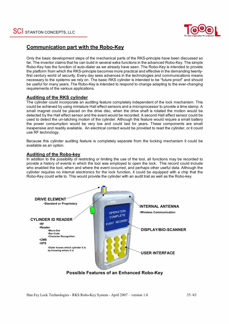
Communication part with the Robo-Key Only the basic development steps of the mechanical parts of the RKS-principle have been discussed so far. The inventor claims that he can build in several extra functions in the advanced Robo-Key. The simple Robo-Key has the function of auto-dialer as we already have seen. The Robo-Key is intended to provide the platform from which the RKS-principle becomes more practical and effective in the demanding twenty-first century world of security. Every day sees advances in the technologies and communications means necessary to the systems we rely on. The basic RKS cylinder is intended to be “future proof” and should be useful for many years. The Robo-Key is intended to respond to change adapting to the ever-changing requirements of the various applications. Auditing of the RKS cylinder The cylinder could incorporate an auditing feature completely independent of the lock mechanism. This could be achieved by using miniature Hall effect sensors and a microprocessor to provide a time stamp. A small magnet could be placed on the drive disc, when the drive shaft is rotated the motion would be detected by the Hall effect sensor and the event would be recorded. A second Hall effect sensor could be used to detect the un-latching motion of the cylinder. Although this feature would require a small battery the power consumption would be very low and could last for years. These components are small inexpensive and readily available. An electrical contact would be provided to read the cylinder, or it could use RF technology. Because this cylinder auditing feature is completely separate from the locking mechanism it could be available as an option. Auditing of the Robo-key In addition to the possibility of restricting or limiting the use of the tool, all functions may be recorded to provide a history of events in which the tool was employed to open the lock. This record could include who enabled the tool, when and where the event occurred, and perhaps other useful data. Although the cylinder requires no internal electronics for the lock function, it could be equipped with a chip that the Robo-Key could write to. This would provide the cylinder with an audit trail as well as the Robo-key.
Possible Features of an Enhanced Robo-Key
DRIVE ELEMENT•Standard or Proprietary
DISPLAY/BIO-SCANNER
USER INTERFACE
CYLINDER ID READER•RF•Reader
•Micro-Dot•Bar-Code•Character Recognition
•CMB•GPS
•Dialer knows which cylinder it is by knowing where it is
INTERNAL ANTENNA•Wireless Communication
SCI STANTON CONCEPTS, LLC
Han Fey Lock Technologies - RKS Robo-Key System - April 2007 – version 1.0 36 /43
Some examples of the advanced Robo-Key Security in case of lost key An example of what may be the simplest RKS key would be a tool that includes a motor, a controller, with a single known combination, a battery and switch to enable the operator to cause the opening function to occur. The operator needs only engage the tool with the installed cylinder press the button, the tool functions, and the lock will become unlocked. An application may be an installation of perhaps fifty parking meters. This looks much like the traditional keyed alike coin box application. With the simple addition of a time circuit in the control element the tool may be programmed to function for only one shift of three hours (nine to noon on Tuesday). After noon the key will no longer function. The Robo-key must be returned to the “dock” to be recharged and reauthorized. A stolen Robo-key would be useless. Security in case of an Emergency entry Features such as Audit Trail, GPS etc may also be included. Another level of interest has been for the use of “first responders” firemen, security personnel, ambulance crews and the like. The problem of urgent access through perimeter fence, doors of all sorts, and barriers has been difficult to solve. A key comprised of two separate elements may be useful. The first element would include the engaging element, the motor, the controller, and the battery. This first element may be maintained, with the battery charged, in a cradle on the dashboard of the emergency vehicle. The second element (the enabling element, with the systems management functions) would be in possession of the crew leader having the authority to open the secure spaces. Enhanced auto dialers will provide more features, and could deal with the who, where, when and why issues as needed for various applications. As mentioned above the key and the features provided may change and improve with the evolving technologies and applications. The “future proof” lock cylinder mechanism is ready to function when needed. The possibilities of this new idea to bring new solutions to old problems are limited only by the imaginations of the people with the authority to take advantage of this novel concept. Security with one-time use locks The security concerns for the various methods of detecting or decoding the combination may be addressed with special embodiments intended to be one-time use devices. When the opening function occurs a frangible component may rupture. The RKS cylinder becomes useless. To re-secure the space a new RKS cylinder would be required. The intercepted or decoded combination of the original cylinder has no value. The low cost and simple means of implementing such a new idea makes this a practical solution to an old problem. This method guarantees an audit trail, traditional seals don’t provide this. When I heard of this idea, my first thought was; how is it different from a seal if you can only open it once and then throw it away. The answer is that the RKS cylinder in addition to resisting surreptitious entry it also provides resistance against forced entry. Something a seal does not do. The security industry is busy with very smart locks such as CLIQ (ASSA), SMART DISC (ABLOY), NEXGEN (MEDECO), CYBERLOCK (VIDEX) and others. All of these are very clever and very expensive, fragile, and with various limitations. The RKS offers an alternative with similar features at a low cost, with great versatility and robustness. The improving electronic technologies are found in the Robo-Key, which may change as needed, not in the installed cylinders, which are hard to change.
SCI STANTON CONCEPTS, LLC
Han Fey Lock Technologies - RKS Robo-Key System - April 2007 – version 1.0 37 /43
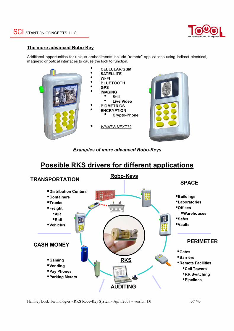
The more advanced Robo-Key Additional opportunities for unique embodiments include “remote” applications using indirect electrical, magnetic or optical interfaces to cause the lock to function.
Examples of more advanced Robo-Keys
Possible RKS drivers for different applications
• CELLULAR/GSM • SATELLITE • WI-FI • BLUETOOTH • GPS • IMAGING
• Still • Live Video
• BIOMETRICS • ENCRYPTION • Crypto-Phone
•• WWHHAATT’’SS NNEEXXTT????
TRANSPORTATION SPACE
CASH MONEY PERIMETER
Distribution Centers Containers Trucks Freight
AIR Rail
Vehicles
Buildings Laboratories Offices
Warehouses Safes Vaults
Gaming Vending Pay Phones Parking Meters
Gates Barriers Remote Facilities
Cell Towers RR Switching Pipelines
Opening Authority
RKS
AUDITING
Robo-Keys

SCI STANTON CONCEPTS, LLC
Han Fey Lock Technologies - RKS Robo-Key System - April 2007 – version 1.0 38 /43
Why is the RKS different? One of the first questions I had was the position of this lock in the existing world of cylinders and keys. Many people are aware that I have a collection of over 600 different cylinders, including several electronic cylinders. Most important I noticed that there are no electronic parts in the RKS cylinder. The lock cylinder is purely mechanical. Only in the version with auditing will there be some simple electronics that are completely independent of the locking mechanism. The only part, which contains electronics in the RKS lock, is the key. I made this table were I put in some information to compare the RKS lock with other locking mechanisms. I tried to compare the RKS lock with the next existing locking mechanisms:
- (High Security) Mechanical pin-tumbler lock with mechanical key (4,5,6,7 pins) - Electronic cylinder - Electro / mechanical cylinder - Mechanical disc combination safe locks - Mechanical disc key safe locks
I combined these groups with the specific cylinder types that I have in my collection, because this way I could give a good comparison. I looked at three points: - The lock cylinder mechanism - The key - Possibility of auditing With this last point I mean to say that the cylinder can be checked to see which key was used to open the cylinder and when. This is a feature, which is standard in most electronic locks I know. In the table below you can see the RKS in comparison with other electro / mechanical locks
Table of comparison RKS with other common locking systems Cylinder Key
Device Example Technology Auditing Battery Technology Auditing BatteryMech, cylinder + key
Pin / disc / mag. tumblers Mechanical No No Mechanical No No
Electronic cylinder
Winkhaus Bluechip Electronic Prog. Unit1 Yes Transponder No No
Electronic cylinder
Cyberlock NexGen Electronic Yes No Electronic Yes3 Yes
Electro / Mech. cylinder
CLIQ Smartdisc
Electronic + high sec. mech. key Prog. Key2 No Electronic +
mechanical Yes3 Yes
Mech. Combo safe lock S&G 6700 Mechanical No No Combo No No
Mech. Key disc safe lock Lagard 2200 Mechanical No No Mechanical No No
Electronic safe lock
Mas Hamilton cdx-07 Electronic Yes Generator Combo No No
Hotel locks Salto I-Button Ving Card Electronic Yes Yes or Hard
wired Electronic No No
Knock’n Lock Knock’n Lock Electro / Mech Yes Yes Electro / Mech No Yes Mech. Disc cylinder RKS Mechanical Optional No Electro / Mech Yes3 Yes
Note: 1. Cylinder / Auditing / Prog. Unit => if you hook this unit, on the cylinder, you can read the transactions in the cylinder. 2. Cylinder / Auditing / Prog. Key => if you insert this key in the cylinder, the data of the lock is transferred to the Prog. key, with a programmer you can read the data in the prog. key. 3. Key / Auditing / Yes => Data about the use of the key is stored in the key, with a prog. unit you can read this.
SCI STANTON CONCEPTS, LLC
Han Fey Lock Technologies - RKS Robo-Key System - April 2007 – version 1.0 39 /43
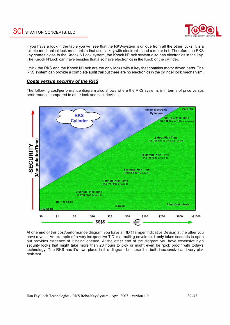
If you have a look in the table you will see that the RKS-system is unique from all the other locks. It is a simple mechanical lock mechanism that uses a key with electronics and a motor in it. Therefore the RKS key comes close to the Knock N’Lock system, the Knock N’Lock system also has electronics in the key. The Knock N’Lock can have besides that also have electronics in the Knob of the cylinder. I think the RKS and the Knock N’Lock are the only locks with a key that contains motor driven parts. The RKS system can provide a complete audit trail but there are no electronics in the cylinder lock mechanism. Costs versus security of the RKS The following cost/performance diagram also shows where the RKS systems is in terms of price versus performance compared to other lock and seal devices:
At one end of this cost/performance diagram you have a TID (Tamper Indicative Device) at the other you have a vault. An example of a very inexpensive TID is a mailing envelope, it only takes seconds to open but provides evidence of it being opened. At the other end of the diagram you have expensive high security locks that might take more than 20 hours to pick or might even be “pick proof” with today’s technology. The RKS has it’s own place in this diagram because it is both inexpensive and very pick resistant.
SCI STANTON CONCEPTS, LLC
Han Fey Lock Technologies - RKS Robo-Key System - April 2007 – version 1.0 40 /43
A practical example how it’s done today and with the RKS lock How it’s done today: The container is secured at the point of origin using a tamper indicative barrier seal attached to the latch handle. The unique identifying number of the seal is made a part of the documentation and the container is shipped to the port of embarkation, perhaps Shanghai. The documents and seal are confirmed and the container processed for loading. Arriving in Seattle the documents are reviewed. If U. S. Customs has a problem, the container is inspected by cutting the seal and inspecting the contents. If everything is ok the container is closed, resealed using a Customs provided seal and sent on its way. Each step is recorded manually using the appropriate tools and procedures. The manual Audit Trail of these several events is subject to all of the many well-known problems. Traditional key function padlocks are not acceptable for this application for the many and obvious issues of key control. How it may be done tomorrow-using RKS concept: The container is secured at the point of origin using a padlock equipped with a RKS cylinder. The cylinder has a unique identifier. This may be a number, bar code, CMB, chip or other appropriate means. The combination of the cylinder would be unknown, but available only to authorized personnel within the secure system. The automated Audit Trail would begin with the scanning and entering of the unique identification of the RKS lock. The container is dispatched, via Shanghai where the RKS lock may be scanned to confirm the secure status of the container and shipped on to Seattle. U. S. Customs might have a problem and need to inspect the contents. In one version of the system the RKS lock is scanned to determine its unique identification. The scanning capacity is included in the Robo-Key and the identification is sent back into the secure system using any of several means, telephone, wireless, satellite, or other. The combination for the specific RKS lock is requested. The system authority confirms the required who, when, where, and why of the request and sends the combination to the Robo-Key, perhaps with a time limit of five minutes. All of these actions and events are within the secure system, the combination is unknown to the operator, and each event is recorded. The RKS lock is opened, the container inspected, closed, relocked and sent on its way. At the final destination the container opened and unloaded. The Audit Trail maintains the complete history of events and assures that secure management of the shipment has been achieved. The system and elements may be as simple or complex as needed to meet the established criteria. The Robo-Key may provide only for the dialing function or include additional features as determined by the system requirements.
• The inventor claims that the combination of this lock can be downloaded to every place on earth. This means that an empty key can be filled with the correct combination via wireless, cellular, satellite, radio or modem (using land lines) technologies. So the Robo-key communicates with the appropriate authority, requests the combination of the specific RKS cylinder, and asks permission to open the lock. If authorized, the required procedures are implemented, permission granted and the process set in motion.
• My thought is that you can compare the Robo-Key with the set-up key safe openers use. There
are different ways to open a lock (without key, and without destructing the lock) you can lock pick it and open it with tools or you can decode the lock, this means that you determine the specific pin lengths, or the specific disc number or lever in lock. With this specific information it is possible to make a specific set-up key, which will open the lock then.
SCI STANTON CONCEPTS, LLC
Han Fey Lock Technologies - RKS Robo-Key System - April 2007 – version 1.0 41 /43
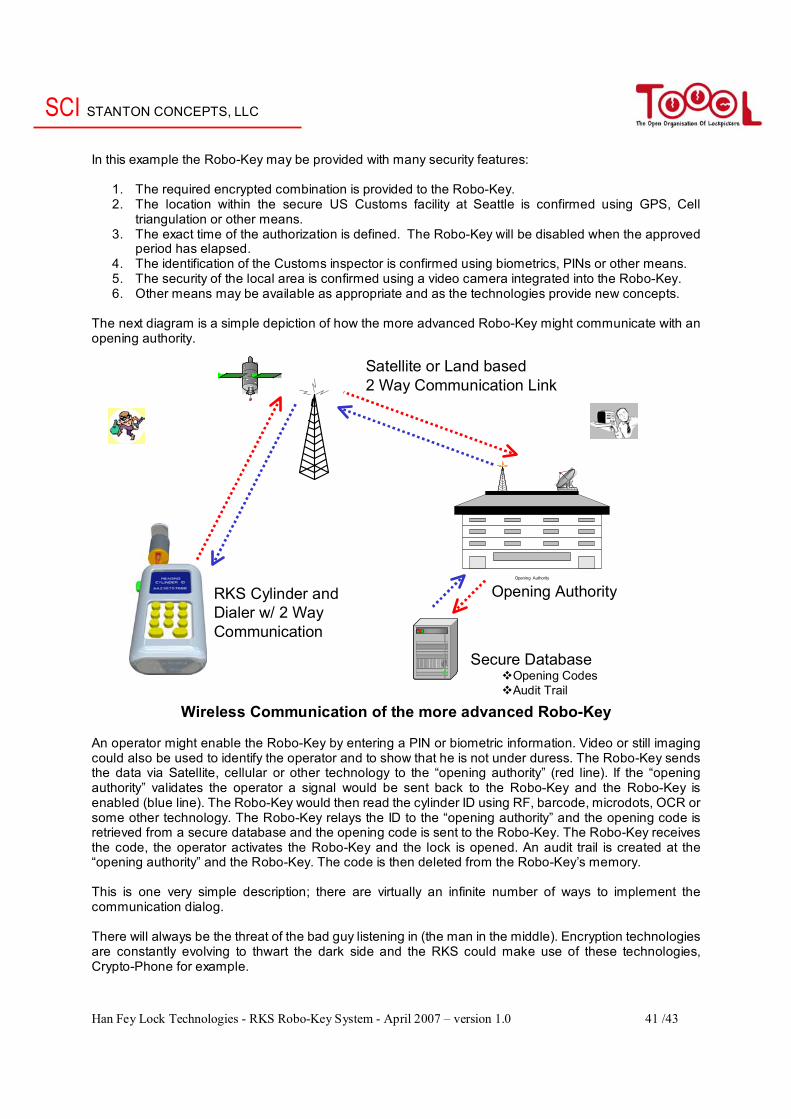
In this example the Robo-Key may be provided with many security features:
1. The required encrypted combination is provided to the Robo-Key. 2. The location within the secure US Customs facility at Seattle is confirmed using GPS, Cell
triangulation or other means. 3. The exact time of the authorization is defined. The Robo-Key will be disabled when the approved
period has elapsed. 4. The identification of the Customs inspector is confirmed using biometrics, PINs or other means. 5. The security of the local area is confirmed using a video camera integrated into the Robo-Key. 6. Other means may be available as appropriate and as the technologies provide new concepts.
The next diagram is a simple depiction of how the more advanced Robo-Key might communicate with an opening authority.
Wireless Communication of the more advanced Robo-Key An operator might enable the Robo-Key by entering a PIN or biometric information. Video or still imaging could also be used to identify the operator and to show that he is not under duress. The Robo-Key sends the data via Satellite, cellular or other technology to the “opening authority” (red line). If the “opening authority” validates the operator a signal would be sent back to the Robo-Key and the Robo-Key is enabled (blue line). The Robo-Key would then read the cylinder ID using RF, barcode, microdots, OCR or some other technology. The Robo-Key relays the ID to the “opening authority” and the opening code is retrieved from a secure database and the opening code is sent to the Robo-Key. The Robo-Key receives the code, the operator activates the Robo-Key and the lock is opened. An audit trail is created at the “opening authority” and the Robo-Key. The code is then deleted from the Robo-Key’s memory. This is one very simple description; there are virtually an infinite number of ways to implement the communication dialog. There will always be the threat of the bad guy listening in (the man in the middle). Encryption technologies are constantly evolving to thwart the dark side and the RKS could make use of these technologies, Crypto-Phone for example.
Opening Authority
Satellite or Land based2 Way Communication Link
Opening Authority
Secure DatabaseOpening CodesAudit Trail
RKS Cylinder and Dialer w/ 2 Way Communication
SCI STANTON CONCEPTS, LLC
Han Fey Lock Technologies - RKS Robo-Key System - April 2007 – version 1.0 42 /43
In locations where wireless is not available the Robo-Key could have a built in modem and talk to the “opening authority” via landlines. With the requirements for security confirmed, the container is opened, inspected, found to be clean, closed and re-secured it is sent on to the destination, Cleveland. Every event experienced by the Robo-key having been carefully recorded in the Audit-Trail database. The RKS-cylinder may include a simple chip to maintain and Audit-Trail of events as experienced by the cylinder. It seems that the discs in the lock are fixed and that the Robo-Key can be programmed. With all modern communication techniques the Robo-Key on the other side of the world can then be programmed to open the lock (temporarily). The lock cylinder however stays unchanged. In my opinion the system is less flexible then the CLIQ system, but this system is also less expensive.
SCI STANTON CONCEPTS, LLC
Han Fey Lock Technologies - RKS Robo-Key System - April 2007 – version 1.0 43 /43
Closing comments So far this article about the RKS lock, the former TOC (Tool Operated Combination lock). One big remark to the readers of this article is that, one has to be careful comparing a conventional disc lock such as Abloy with the RKS. Although they share some similarities they are two very different locking mechanisms. In a conventional disc cylinder (Abloy, Baton, Abus Granit, Lagard 2200) the discs are aligned simultaneously with a simple machined key and the discs never rotate more than 90° before they are properly aligned. The discs in the RKS cylinder spin freely and are aligned sequentially (disc 1 than disc 2 than disc 3, by a separate auto-dialer) just like with an S&G safe combination lock. I assume that the lock comes close to this type of lock, but then with a dial, which is replaced with a Robo-key, therefore the lock could have more discs in the locking mechanism, which makes the lock actually safer against manipulation etc. I called this lock unique because of the next features / advantages: - No keyway No opportunity for surreptitious attack - Low cost, simple, purely mechanical cylinder Future proof - User blind to combination possible manual override Security - Environmentally robust versatile applications - Manipulation resistant Security - Audit trail – Cylinder and Robo-Key Security and management - High number of permutations Security - Robo-Key functionality Security, versatility, applications - Future proof / Innovative Management - Versatile Wide variety of applications These were the things, which attracted me when I saw the lock, this also besides the fact that I like disc locks, and then referring to the more then 200 different Abloy locks I have in my collection. Of course every lock can be opened with force, but I think that the time of pin-tumblers is passed, because there are a lot of techniques nowadays to by-pass these systems with minor damages. I refer then to Lock picking, Bumping, Impressioning, John Falle Tools, Easy Entrie, Key copying, etc. Maybe the RKS, a totally new idea can have the future, because it withstands (at the moment) all these attacks. Fact is that this lock is not in production (yet) and that the inventor is looking for strategic partner(s) to make the RKS a reality. I know both inventors of this system and they both believe in the RKS mechanism. If the lock is really that future-proof as they claim that it should be, only the future can tell. With this article I wanted to make the people aware of the existence of this unique mechanism. You can download this file with the next link “www.toool.nl/RKS-principle.pdf” where you can see the pictures in this article more clearly and in color. If you have a question or discovered not correct things in this article, you can contact me at: [email protected]. For deep going information about the lock, you can contact one of the inventors, John Loughlin at: [email protected], or you can visit their website: www.stantonconcepts.us In my next article I hope to continue with more mechanical locks and I will therefore discuss all the existing ASSA Twin systems. I already started this article up and I have already about 40 pages about this item. I hope you have enjoyed reading this article. Han Fey Han Fey Lock Technologies The Netherlands
Related Documents