School of Metallurgy and Materials Master by Research (MRes) Dissertation Direct Laser Fabrication of Ti-5553 Submitted by: Arash Hatefi Supervisor: Dr. Moataz M.Attallah

Welcome message from author
This document is posted to help you gain knowledge. Please leave a comment to let me know what you think about it! Share it to your friends and learn new things together.
Transcript

School of Metallurgy and Materials
Master by Research (MRes) Dissertation
Direct Laser Fabrication of Ti-5553
Submitted by:
Arash Hatefi
Supervisor:
Dr. Moataz M.Attallah

University of Birmingham Research Archive
e-theses repository
This unpublished thesis/dissertation report is copyright of the author and/or third
parties. The intellectual property rights of the author or third parties in respect of this
report are as defined by The Copyright Designs and Patents Act 1988 or as modified by
any successor legislation.
Any use made of information contained in this thesis/dissertation report must be in
accordance with that legislations & regulations and must be properly acknowledged.
Further distribution or reproduction of this thesis/dissertation report in any format is
prohibited without the expressed permission of the copyright holder.

ACKNOWLEDGEMENTS:
I would like to express my gratitude and love to my family for their continuous support
and never ending understanding during my study.
Great appreciation goes to my supervisor Dr. M. M. Attallah and also Dr. Ravi
Aswathanarayana Swamy and for his unconditional help and support. I always
appreciate their support during this part time study, taking into notice my situation with
full-time employment and the support provided to me during this time.
I would also like to express my gratitude towards the School of Metallurgy and Materials
at the University of Birmingham for offering me the opportunity to study part time.
Great appreciations towards my colleagues at Messier-Bugatti-Dowty Reasearch &
Development department, Mr. Simon Harris & Garmain Forgeoux and Przemyslaw
Grochola. Special thanks to my department manager Mr. Colin Jones, MBD Supplier
Quality Manager, for giving me the chance and the opportunity for pursuing my study,
despite the busy work schedule in the department.

ABSTRACT
Titanium alloy Ti-5553 PREP® powder has been processed using Direct Laser
Fabrication (DLF) technology to assess the feasibility of using DLF to produce
certain features on existing aerospace structures, in a hybrid additive layer
manufacture (ALM) approach. A range of laser processing conditions has been
utilised in order to understand the influence of those conditions on the
mechanical properties and microstructure of the DLFed samples.
The experiments showed that processing parameters have significant effect on the
properties of the DLFed samples. Those effects were not just limited to the
physical properties but also affect the metallurgical properties of the samples.
Grain sizes found to increase in size as the build progresses. The micro-section of
the interface and the deposition layers did not show any sign of porosity.
Within the present work, Optical microscopy and Scanning Electron Microscopy
(SEM) were used to assess the microstructure of the DLF produced samples.
Heat treatment cycles have been reviewed to establish the most effective method
for improving the properties of as-DLFed samples to achieve the desired
properties. Ageing cycles as well as Solution treat + Ageing cycles have been
considered and the mechanical properties tested for samples in each condition.
The microstructures showed that as-DLFed samples did not contain the α-
precipitates necessary to achieve the desired mechanical properties. Ageing cycle
can slightly improve those properties but only through the solution treatment and
aging cycle, the desirable mechanical properties can be achieved. Once the
samples are Solution treated and aged, significant volume of primary α-phase
would precipitate within the aged β-matrix.

ACKNOWLEDGMENTS
Table of contents
1 LITERATURE REVIEW .................................................................................. 4
1.1 Introduction to Titanium ................................................................................................ 4
1.2 Titanium and its alloys ................................................................................................... 4
1.3 Heat treatment of Ti 5553 ............................................................................................ 11
1.4 Laser Fabrication technology ....................................................................................... 13
1.5 Comparison of DLF with Conventional Processing Technologies .............................. 16
1.6 Process parameters ....................................................................................................... 20
1.7 Powder manufacturing method .................................................................................... 23
1.8 Nozzles & Powder size ................................................................................................ 26
1.9 Summary of Literature Review .................................................................................... 29
2 EXPERIMENTAL PROCEDURES................................................................. 31
2.1 Materials ....................................................................................................................... 31
2.2 Ti-5553 Powder Characterisation................................................................................. 31
2.3 Direct Laser Fabrication ............................................................................................... 34
2.4 Preliminary Studies ...................................................................................................... 36
2.4.1 Stage 1: Ti5553 on Ti6Al-4V substrate ....................................................................... 38
2.4.2 Stage 2: Ti5553 on Ti-5553 substrate .......................................................................... 39
2.5 Optical microscopic evaluation .................................................................................... 41
2.5.1 Image analysis on micro-sections ................................................................................ 41
2.6 Mechanical tests on sectioned samples ........................................................................ 42
2.6.1 Micro-hardness testing on deposited samples .............................................................. 42
2.6.2 Tensile test.................................................................................................................... 43
3 PROCESS ANALYSIS AND DISCUSSION .................................................... 45
3.1 DLF of Ti-5553 ............................................................................................................ 45
3.2 Observation after the first DLF stage: .......................................................................... 46
3.3 Ti-5553 deposition of Ti-5553 substrate: ..................................................................... 47
3.4 Dimensional evaluations and analysis: ........................................................................ 49
3.5 Microscopic Evaluation: .............................................................................................. 51
3.6 Microstructural Improvement ...................................................................................... 60
3.7 Discussion: ................................................................................................................... 66
4 CONCLUSION ............................................................................................... 71

4.1 Study results ................................................................................................................. 71
4.2 Limitations: .................................................................................................................. 72
4.3 Future work .................................................................................................................. 73
APPENDIX A - POWDER ANALYSIS RESULTS ..................................................... A-1
APPENDIX B - MODEL DESIGN ............................................................................. B-1
APPENDIX C - TENSILE TEST RESULTS .............................................................. C-1
REFERENCES: ...............................................................................................................

Introduction
Landing gears are major part of all aircrafts flying around the world. Safely
taking off and landing of the commercial aircrafts as well and military planes are
dependent on the safe and correct deployment of those aircrafts landing gears.
The need for improved and cost-effective processes as well as smarter material
utilisation has led to recent developments and advances in near net-shape
technology and processes.
This project has been established and undertaken in order to evaluate the
practicality of using direct laser fabrication (DLF) technology, to produce
features such as holding lugs on landing gear parts using Ti-5553 alloy. The main
objective in this project is to establish if the DLF process can be utilised to
produce such features on the blank forged pats, instead of complicated forging
dies with excess material that need to be partially or completely removed during
the follow up machining processes.
The research project will focus on the fabrication of lugs on “Truck Beam” for a
major aircraft manufacturer main landing gear. At present, truck beam is
produced from forging blanks and the lugs are an integrated part of the forging.
Figures 1 and 2 show the graphic representations of the truck beam, in the as-
forged condition and following the completion of all machining operations.
Figure 1: Part of the landing
gear truck beam in the as-forged
condition. The lugs are
produced at the forging stage.
Picture courtesy of MBD
Gloucester Ltd.

Further information about the design and manufacture of the truck beam are
described in Appendix B.
Section 1 of this report provides an introduction into titanium and its alloys, in
particular Ti-5553 which is the subject of this investigation. The literature
review section explains the researches carried out in the Direct Laser
Fabrication method as well as metallurgy of Ti-5553.
Section 2 explains the experimental procedures used during this study. The
section discusses the material, preparation and composition, Ti-5553 powder
used for the deposition process, process parameters setup for DLF process, the
experimental program and the number of samples, fabrication stages,
microscopically evaluation methods and mechanical test procedures.
Section 3 explains the variation within processing parameters which were
reviewed and modified to obtain the desired fabricated samples. The section
also describes the experimental procedures for the initial deposition and
fabrication of the Ti-553 samples and the metallurgical and mechanical tests
carried out. The improvements within the microstructure achieved through heat
treatment cycles on the fabricated samples will also be described in this section.
Section 3 also presents and discusses the results obtained from the
experimentation. Those results include the initial microstructure, hardness test
Figure 2: The same
part as figure 1 after
machining operations.
Picture courtesy of
MBD Gloucester Ltd.

results and mechanical test results in comparison with Ti-553 in forged
condition. The results following the rectification processes will also be
discussed in this section.
It must be noted the concept of the Design of an Experiment was discussed and
considered in section 3; however the number of test samples that were produced
satisfactorily as the result of variations of the processing parameters did not
produce adequate information to investigate correlations between the processing
parameters and the volume of the porosity within the micro-section.
Section 4 summarises the results and presents the conclusions from the thesis,
explaining the effects of processing parameters and rectification processes to
improve the microstructure of deposited Ti-5553. This section also suggests
future work to be carried out to further investigate the DLF parameters and the
effects of those parameters on the material properties.

Page 4 of 74
1 Literature Review
1.1 Introduction to Titanium
Titanium and its alloys are relatively new to the field of structural materials
compared with steel and aluminium alloys. Discovered in 1790 by W. George
and M.H. Klaproth [1], the interest in using Titanium as a structural material
began to develop in 1940’s and 1950’s. This interest was the result of high
specific strength, excellent corrosion resistance and fracture toughness compared
to traditional metals such as steels and stainless steels.
The following section will give an overview on the titanium alloy classes, and
their respective properties.
1.2 Titanium and its alloys
Various industries use a wide range of pure and alloyed titanium in various
product forms such as mill products, castings, forgings and powder metallurgy
product. However not each alloy or grades of titanium is available in all forms
and sizes of products. In many cases, alloying elements are added to pure
titanium to improve certain properties of the material. The following sections
briefly explain the roles of alloying elements in developing titanium alloys.
When alloying elements are added to Commercially Pure Titanium (CP Ti),
Titanium develops a number of features that separate this material from the other
light metals and make its physical metallurgy both complex and interesting. A
summary of those features is listed here:
At 882˚C pure Ti goes through an allotropic phase transformation from a
Hexagonal Close Packed (hcp) microstructure to the Body Centred Cubic (bcc) or
beta (β) phase that stays stable up to the melting point. It is the result of this

Page 5 of 74
transformation and similar to steels, various heat treatment processes would
develop α, β or mixed α/β microstructure alloys. [2]
Titanium is considered as a transition metal containing an incomplete shell in its
electronic structure that enables this material to form solid solutions
microstructures with most alloying elements having a size factor within ±15%.
[3]
1.2.1 Alloying Elements
Both mechanical and physical properties of titanium are greatly affected by
adding alloying elements to it. Each alloying element that can be added to
titanium in either small or large amounts, would change the basic crystal structure
of the material that in turn would affect the strength of the material.
Apart from the change in the strength of titanium, the change in the crystal
structure transformation is another major effect of addition of alloying elements
to titanium. The transformation that happens at about 882ºC in CP-Ti. This effect
is in the form of increase or decrease on the transformation temperature and
depends on the type of the added alloying element. Based on the effect of the
alloying elements on the distortion of the crystal structure, this effect can be
stabilisation of either α or β phases at lower temperatures.
Titanium alloy phase diagrams are often complex and are not readily available.
However in general 3 categories of titanium alloys are developed through
addition of alloying elements, as shown in figure 1-1: α and near α alloys, α+β
alloys and β alloys.

Page 6 of 74
α and near α alloys:
α-alloys are the result of addition of alloying elements that stabilise the α-phase
such as Fe or V. The mechanism of the stabilisation is by the increase in the α/β
transus temperature. The microstructure of α-alloys mainly consists of α phase
with the small amount of β phase precipitated at α grain boundaries [4]. α-alloys
do not show good weld-ability because of a lack of response to heat treatment
and are good for sub-zero applications as they do not have a ductile-to-brittle
transition. Forge-ability of the alloys is not good as the result of the “hcp”
structure of α phase. α-alloys have excellent corrosion resistance properties since
the oxide layer is very stable.
α/β alloys:
The α/β titanium alloys are the mostly used titanium alloys for commercial
applications. This category of titanium alloys accounted for more than half of all
titanium usage in the U.S. in 1998 with 56% of the total usage being Ti-6Al-4V
Figure1-1: Basic types of phase diagrams for titanium alloys. The dotted
phase boundaries in (a) refer specifically to the Ti-Al system. The dotted
lines in (b) and (c) show the Martensite start (Ms) temperatures. Alloying
elements favouring the different types of phase diagrams are (a) Al, O, N,
C, Ga; (b) Mo, W, V, Ta; (c) Cu, Mn, Cr, Fe, Ni, Co, H. [1]

Page 7 of 74
[4]. In comparison to near α-alloys, a small but considerable volume fraction of
β-phase is still present at room temperature as the result of the presence of α and
β stabilizing elements. An attractive balance of characteristics including a
positive combination of strength, ductility, fatigue and fracture properties is
developed within this group of alloys due to the combination of the
characteristics of each phase. The microstructure can be changed by modification
of the solution and aging temperatures and times and also cooling rates from
above the β transus. [4]
α/β titanium microstructures are formed by addition of alloying elements which
depress the α/β transus and increase β-phase stability. Those alloying elements
may be classified in two categories: a) those elements that develop binary
systems of the β-isomorphous [5] type (figure 1-1(b)) and the group of element
that increase chance for formation of a β-eutectoid (figure 1-1(c)).
Metastable β alloys:
Titanium alloys containing adequate quantities of β-stabilisers to hold back the
Martensitic transformation and subsequently retaining the bcc crystal structure on
quenching to room temperature are classified as Metastable β-titanium alloys. [6]
A large volume fraction (~ 40%) of β-phase is retained within the β-metastable
titanium alloys at room temperature after heat treatment. The microstructure
contains initial β-grains and the α-phase precipitating with various morphologies:
needles, nodules, etc. This group of alloys have high tensile and fatigue strength
but poor elevated temperature creep and oxidation resistance. [6]
Addition of β-stabiliser elements to the alloy would result in the reduction of the
beta transus temperature down to below room temperature and subsequently a
stable β-Ti alloy [7]. Metastable β-Ti alloys exhibit good formability [8] and
although it is well known that beta titanium alloys do not work harden

Page 8 of 74
significantly, a significant rate of work hardening has been reported by J. Ph.
Guibert & et al. for Ti–20V under compressive testing [9]. However the
deformation and work hardening properties of various titanium alloys are not
covered as part of this study.
Metastable β-Ti alloys are typically subject to a thermo-mechanical treatment to
precipitate additional phases. Through solution treating and precipitation of α, ω
phase and/or intermetallic yield strength and fracture toughness of these alloys
can be improved. The morphology, size and distribution, of these precipitates
greatly affect the mechanical properties of the alloy. [7]
Metastable β alloys do not form martensite but retain the β phase after quenching
to room temperature. As the result of high hydrogen tolerance of the β-phase, the
corrosion resistance of metastable alloys is good and in some aspects even better
than α/β alloys. Due to slow α-phase kinetics, thick sections of these alloys can
be heat treated to produce a constant microstructure. [7]
1.2.2 Ti-5553 development
Near β titanium alloys, that can be quenched to room temperature whilst still
retaining a fully β phase microstructure, are candidates for use in many
demanding structural applications where light weight and high-strength are
required.
A recently-introduced alloy Ti–5Al–5Mo–5V–3Cr (Ti-5553) (based on Russian
patented alloy VT 22 Ti-5.7Al-5.1V-4.8Mo-1Cr-1Fe) is a near β titanium alloy
developed for a number of thick-section aerospace components due to its high
strength and deep hardenability [11, 12]. The addition of Fe to these alloys has
improved the sintering properties of the material for powder metallurgy
applications [12].

Page 9 of 74
Titanium Ti-5553 (Ti-5Al-5Mo-5V-3Cr) also known as Timetal, is a metastable
β titanium alloy that as previously mentioned has been developed from Ti-5.7Al-
5.1V-4.8Mo-1Cr-1Fe. As reported by B.A. Welk in his research report [14] Ti-
5553 alloy was initially introduced for aircraft industry in form of large size
forgings due to the higher strength of this alloy compared to VT22 as well as
reasonable ductility. A combination of strength, ductility and toughness
improvements has made this alloy significantly more attractive for such forging
applications.
S.L. Nyakana, et al. [15] explain that as the result of slow diffusion kinetics of
Mo and Cr, the produced α-phase dispersion is refined and subsequent strengths
as high as 1517 MPa can be achieved although with limited ductility.
The high hardenability of this alloy allows sections up to 6” thick to be heat
treated and air cooled with an insignificant reduction in strength when compared
to Ti-10V-2Fe-3Al which has a thickness limit of 3” and must be water cooled
[16]. This hardenability and relative ease of production are responsible for
Ti5553 replacing Ti-10V-2Fe-3Al used on previous designs of landing gears
[17]. Once the material is solution treated above its beta transus temperature, then
a lamellar or bi-lamellar (secondary α) microstructure can be produced. Solution
treatment below its β transus temperature would develop a bimodal
microstructure.
As mentioned above, Ti-5553 alloy is used for parts such as large landing-gear
forgings and high-strength fasteners in the new generation of commercial
airliners [17]. As described by G.Lutjering [18] the slow precipitation kinetics of
α-phase compared to other β titanium alloys such as Ti-10-2-3 makes Ti-5553
alloy a good candidate for thick section forgings for high strength airframe
components such as landing gears or flap tracks.

Page 10 of 74
Considering the recent developments on Ti5553 alloy, few technical papers are
currently available investigating mechanical and various properties of this alloy
under different conditions. However J.C.Fanning [19] study of Ti-5553 (referred
to as TIMETAL) suggests that the alloy in solution treat and aged condition could
achieve the following mechanical properties:
Further studies have been carried out on the influence of alloying elements on
precipitation of α-phase in Ti-5553. Study on the influence of carbon on such
precipitation [20] concludes that carbon affects the precipitation of isothermal ‘ω’
at low ageing temperatures, but not at higher temperatures. Also the precipitation
of α phase during ageing stage is not strongly affected either by the presence of
carbon or by low-temperature ageing when the material is quenched from below
the β transus.
The study also suggests that the balance of mechanical properties in Ti-5553 is
expected to be dependent on the volume fraction, size, morphology and
distribution of α-precipitates within the β-matrix. By varying the heat treatments
parameters such as temperatures, times and cooling rates, various volume
fractions and morphologies of α-phase nucleated within the β-matrix phase can
be achieved in this alloy. The partitioning of the alloying elements, Al, V, Mo, Cr
and Fe, also depends on the applied heat-treatments. Furthermore, in addition to
these primary alloying elements, interstitials such as oxygen and hydrogen can
also play a significant role on the development of the microstructure in this alloy.
The nucleation sites for α-phase within the β phase of this alloy include prior β
Table 1: Average
longitudinal
mechanical properties
of TIMETAL 5553, 22
mm (0.87 in.) bar in
solution heat treated
plus aged condition as
studied by J.C.Finning
[19]

Page 11 of 74
grain boundaries, β/ω interfaces, β/β’ interfaces and other defects such as
dislocations and intermetallic particles within the matrix [21].
Figure 1-2 shows the microstructure of the Ti5553 using SEM microscope. The
β-phase is white and the α-phase is dark.
1.3 Heat treatment of Ti 5553
The response of Ti5553 to heat treatment has been subject to a number of studies.
Shevel’kov [22] performed his work on study of the phase transitions in VT-22
upon water quenching to room temperature from 950°C. Using x-ray analysis, the
study showed that there was β-decomposition upon quenching. The study also
suggests that α'' appearance has occurred by a shear mechanism in the β solid
solution starving regions. Nucleation of α from the β starving regions was seen to
occur at 500°C after only 0.1h.
A.Dehghan & R.Dippenar studied [13] the isothermal heat treatment of Ti-5553
and concluded ageing time and temperature have direct impact on the volume
fraction of α-phase precipitated from the β-matrix. The study suggests that by
increasing the aging temperature from 625K to 725, the volume fraction of
precipitated α-phase was increased by 6 times from 5% to 30%. The ageing
Figure 1-2: SEM BSE
image of Ti5553
microstructure
showing β-phase in
white and the α-phase
in dark contrast. [17]

Page 12 of 74
temperature also changes the morphology and size of precipitated α. The study
was carried out from solution treatment and only considers the effect of ageing
cycles.
B.A. Welk’s study [14] previously discussed also refers to the study of heat
treatment of Ti-5553 carried out by Orlova [23] for the changes in microstructure
caused by varying the T1 (solution) temperature and the T3 (aging) temperature
of an industry standard heat treatment . B.A. Welk explains that the study
mentioned herein has concluded that the rate of the grain growth is significantly
higher at Solution temperatures (T1) which results in lowering the strength and
the ductility of the samples. At that temperature the β-matrix also changes and
coarse α-laths stat appearing along the grain boundaries. On the other hand,
reducing the T1 temperature will cause an increase in the spreading of the
secondary α-phase alongside a reduction in the precipitation of the tertiary α-
phase.
Material specification MTL 3103 [24] has been specifically developed by
Messier-Dowty Ltd describing the requirements for Titanium Ti-5553 alloy and
the responsibilities of raw material and forging producers in the production of
ingot, bars and forging stocks for subsequent heat treatment to a tensile strength
of at least 1240 MPa at ruling sections up to and including 150 mm. However due
to the confidentiality of the material specification, only the essential requirements
of this material as applicable to this study have been described herein. The
microstructure requirements of MTL 3103 [24] after the heat treatment, are that
the microstructure shall consist of a primary alpha phase in an aged beta matrix.
A continuous alpha phase network along beta grain boundaries is undesirable, but
need not be a reason for rejection if the tensile and K1C characteristics are
satisfactory. The reference heat treatment requirements as specified by MTL
3103 are:

Page 13 of 74
(1) Solution heat treatment: soak for 2 hours at a temperature of (βT – 40 °C
±10 °C) (βT – 72 °F ±18 °F).
(2) Air cool
(3) Ageing treatment: soak for 8 hours at 610°C ±5 °C (1112 ±9 °F)
(4) Air cool
Following the above reference heat treatment, the mechanical properties of the
material shall meet the requirements of table 2:
Direction
0.2% Proof
Stress MPa
Tensile Strength MPa Elongation %
Min Min Target Max Min
Longitudinal 1170
(170)
1240 1290 1410
(180) (186) (205)
6
Transverse 1170
(170)
1240 1290 1410
(180) (186) (205)
4
1.4 Laser Fabrication technology
Direct Laser Fabrication, also known as Directed Metal Deposition, Laser
Powder Deposition, Laser Direct Manufacturing and Electron Beam Free Form
Fabrication, is a rather recent development that can potentially help to reduce the
cost of manufactured parts. A focused laser beam is used to melt powder and
deposit the melt in a predetermined path on a substrate as shown in figure 1-3.
Table 2: Mechanical properties requirements from Messier-Dowty MTL
3103 [36]. Vales in ( ) are in KSI

Page 14 of 74
The metal deposited perform is then machined to the final part shape. Such near
net-shape manufacturing method once adequately developed and optimised,
could lead into saving in materials, machining costs and cycle times over
conventional forged or machined parts. [25]
Direct laser fabrication (DLF) is a technology that utilises the basis of laser
cladding to create 3-D metallic structure by layer by layer deposition of molten
material. Today, 2 main types of laser fabrication technologies are being used:
Powder bed and Direct Laser Fabrication (DLF). Although it must be noted that
the Powder laser bed technology was initially developed for rapid prototyping
and later on it has been developed for the production of engineering components.
In this technology, successive layers of powder are spread uniformly across the
bed and a laser follows a path defined by a CAD program to produce a 2-D slice
of the component. The bed is then lowered and the next layer of powder is spread
over the previous layer. The increment in the height of the component is
developed by this downward movement of the bed. The unused powder on the
powder bed is loose and can be completely recycled.
Figure 1-3: Typical application
of DLF. The laser is used to
generate a molten bath on the
prepared surface. Powdered
material is guided through the
nozzle, step by step. Once the
new material has cooled, the
next layer is deposited , or the
refinishing process starts.
Image courtesy of Trumpf
Groppe.

Page 15 of 74
Similarly the DLF technology also utilises focusing of a high power laser onto to
a small focal point, typically 1-2mm in diameter whilst the metallic powder is
also blown into this focal point. At this spot, the high power densities of laser
induce large thermal gradients resulting in the formation of a melt pool. Metal
powders are delivered at the focal spot either through gravity or by the pressure
of an inert gas. The inert gas also creates a shield around the molten pool to
reduce the risk of oxidisation. Through movement of the table in both X and Y
directions, layer by layer deposition is carried out on a substrate. Figure 1-4 [26]
shows a schematic setup of the DLF process.
The size of powder used in the powder bed technology is less than 20μm
compared to the typical powder sizes used in the direct feed technology which
tend to be around 90 – 120μm. As the result, the surface finish of powder bed
products is far smoother than in typical DLF components, however this
improvement is achieved by compromising the cost of very small Z increments,
hence the prolonged build-time.
In DLF technology, the powder is fed at a controlled rate into the focal point of
the laser where it is melted into the melt pool, as the movement of the laser
follows the path defined by a CAD (computer aided design) file of a component;
Figure 1-4: Schematic
diagram of DLF process. The
main elements of the process
include: The laser source, the
focal point size, the powder,
and the carrying gas. [26]
LASER Mirror

Page 16 of 74
this CAD file controls the movement of the sample in the X–Y plane and the
movement of the laser along the Z axis.
This technology is particularly well suited to the repair of components and is
currently being applied to the repair of compressor and turbine blades and of
tooling. A study on the net shaping manufacturing of Aeroengine Components
using DLF technology [27] used a 3-D finite element model to simulate the
thermal profile of a Ti 6-4 sample during the fabrication stage using DLF
technology. The results showed a good match between the predicted and
measured thermal profiles. The thermal profiles at various locations on the
fabricated parts were also consistent with the microstructures obtained.
1.5 Comparison of DLF with Conventional Processing Technologies
DLF is a direct metal deposition process that delivers metal powders into the
focal point of a high power laser beam, melts the powder and creates a fully-
dense metal deposit. Direct metal deposition can be equipped with computer-
based design and numerical control to form 3D near-net shaped parts. It can be a
waste-free or waste-minimised process, because it is performed in a high purity
inert gas environment in which powder that is not melted by the laser, can be
recycled and may be used again. This feature makes the process particularly
attractive for expensive, high-performance materials or hazardous materials that
require containment during processing. In addition, since the one-step process
deposition process produces near-net shape components, further cost savings
through reduction or avoidance of further conventional machining, forming
operations or powder metallurgy operations are also possible. In addition, higher
purity materials can be provided with the elimination of contamination pick-up
from cutting tools, dies and forming surfaces, lubricants or cleaning agents. Cost
savings can also be achieved through reductions in handling and storage costs, as
there are no intermediate processing steps.

Page 17 of 74
1.5.1 Feeding methods
Laser fabricated structures can be produced using Powder or Wire for deposition.
Recent studies have been carried out on the differences between the deposition
microstructure of these two methods of deposition. W.U. Syed et al. [28] studied
the DLF process using wire and powder feeding method on steel family of
material; however the concept of wire feeding and powder feeding systems can
be expanded to Titanium. Figure 1-5a shows the typical setup of the wire feeding
system. The study investigated the effects of feeding direction and location and
concludes that the best feeding direction for the wire was from the front,
compared to the results when the wire was fed from the rear as shown in figure 1-
5b.
The results obtained for powder feeding showed noticeable differences compared
to wire feeding system. High catchment efficiency was observed when the
powder was fed from the front; an increase of 20–45% in efficiency compared to
the rear powder feeding for the same operating conditions was reported by the
study. However, rear powder feeding resulted in less oxidation and a 20%
decrease in the surface roughness.
Nonetheless the study concluded that no noticeable difference could be noticed
between the microstructure of the Powder and wire fed system. The micro-
structures of both methods were reported mainly as dendritic and cellular with a
cell size between 2 and 15 µm. The study also reported that a finer structure was
found in the first layer near to the substrate and then the grain size became
coarser on moving up the sample. The top layer showed a mainly dendritic
structure and these structures was also seen to prevail at layer boundaries.
Page 18 of 74
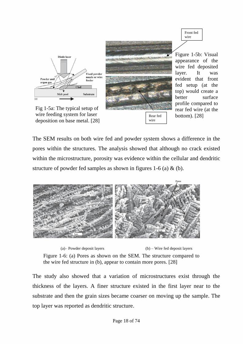
The SEM results on both wire fed and powder system shows a difference in the
pores within the structures. The analysis showed that although no crack existed
within the microstructure, porosity was evidence within the cellular and dendritic
structure of powder fed samples as shown in figures 1-6 (a) & (b).
(a)– Powder deposit layers (b) – Wire fed deposit layers
The study also showed that a variation of microstructures exist through the
thickness of the layers. A finer structure existed in the first layer near to the
substrate and then the grain sizes became coarser on moving up the sample. The
top layer was reported as dendritic structure.
Direction of the movement of the substrate. Fig 1-5a: The typical setup of
wire feeding system for laser
deposition on base metal. [28]
Figure 1-5b: Visual
appearance of the
wire fed deposited
layer. It was
evident that front
fed setup (at the
top) would create a
better surface
profile compared to
rear fed wire (at the
bottom). [28]
Front fed
wire
Rear fed
wire
Figure 1-6: (a) Pores as shown on the SEM. The structure compared to
the wire fed structure in (b), appear to contain more pores. [28]

Page 19 of 74
Other studies [29] on the DLF process has been carried out for the purpose of
comparison between 2 different titanium alloys: Ti-6Al-4V and a burn resistant
titanium alloy Ti-25V-15Cr-2Al-0.2C known as "BurTi”. In the study, Special
modifications had been carried out on the powder nozzle in order to ensure the
powder feed rate can be adequately controlled. Microstructure analysis of the
deposited sample made of wire fed reported to be dominated by columnar grains
as shown in figure 1-7a. The study suggests that during laser fabrication, Ti6-4
tends to grow on the previous layer; whereas in laser fabricated BurTi as
described in other literatures [30], nucleation normally takes place in every layer
of the deposition. The study also suggests that small amount of BurTi would
change the microstructure of Ti6-4 from epitaxial growth and subsequently
columnar structure as shown in figure 1-7a to nucleation dominating in the
deposition so that equiaxed grains form as shown in figure 1-7b.
Despite the obvious advantages of the wire fed system, it was deemed impractical
to use this system for the purpose of this project since the main focus of this
Figure 1-7a: Epitaxial &
Columnar growth of the Ti6-4
[29]
Figure 1-7b: EBSD map showing the
equiaxed microstructure which is present
in most of a build and much smaller
equiaxed grains between the successive
layers. [30]
Page 20 of 74
project is on Ti-5553 alloys. At the present study, only powder form of this
material can be produced.
1.6 Process parameters
One of the most important processing parameters affecting the microstructure of
all metals is the cooling rate from the melt temperature. The laser power used for
the wire-fed system has been reported up to 3 times higher than the power used
for the powder fed system. Therefore the temperature of the melt pool in the
wire-fed system would be significantly higher that the powder fed system. This
higher temperature would result in a significantly reduced cooling rate compared
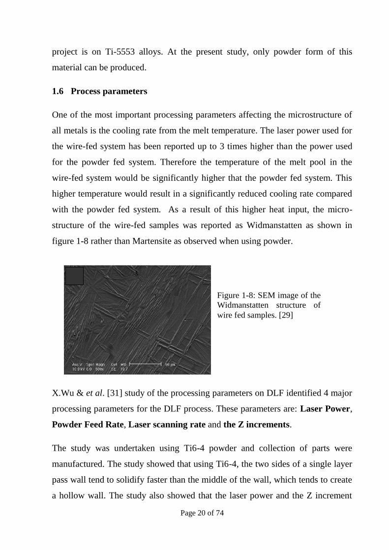
with the powder fed system. As a result of this higher heat input, the micro-
structure of the wire-fed samples was reported as Widmanstatten as shown in
figure 1-8 rather than Martensite as observed when using powder.
X.Wu & et al. [31] study of the processing parameters on DLF identified 4 major
processing parameters for the DLF process. These parameters are: Laser Power,
Powder Feed Rate, Laser scanning rate and the Z increments.
The study was undertaken using Ti6-4 powder and collection of parts were
manufactured. The study showed that using Ti6-4, the two sides of a single layer
pass wall tend to solidify faster than the middle of the wall, which tends to create
a hollow wall. The study also showed that the laser power and the Z increment
Figure 1-8: SEM image of the
Widmanstatten structure of
wire fed samples. [29]

Page 21 of 74
have greater effect on the microstructure of the fabricated part. A medium laser
power of 245W had produced a nearly 100% dense structure whereas the higher
power of 390W some pores were reported at the primary β grain boundaries.
Lower laser powers of 180W developed porous structure with connected pores up
to 300μm diameter. This experiment was carried out using a feed rate of 6 g/min,
scan speed of 200 mm/min and a Z increment of 0.3 mm/min.
The laser scanning speed also has a significant impact on the properties and the
microstructure of the deposited layers. The study also concluded that within a
range of the scanning speeds, increasing the speed would lead to a finer
microstructure up to a point but the microstructure becomes coarser at the
extreme speed of 1000 mm/min. It must be noted that the powder feed rate was
also increased from 6 to 18 g/min in order to compensate for the higher speed
rates. A summary of the results obtained within the study is shown below (figures
1-9a to 1-9c & 1-10a to 1-10c) with representative images.
Figures 1-9a to 1-9c : SEM images
showing Ti–6Al–4V parts
manufactured using DLF; SEM
micrographs showing different
microstructures produced at different
laser powers of (a) 390W, (b) 264W
and (c) 180W. The best microstructure
has been achieved at 264W at a powder
feed rate of 6 g/min, scan speed of 200
mm/min and Z-increment of 0.3 mm.
[31]
200 µm
10 µm
1-9a
1-9b
1-9c

Page 22 of 74
It has been concluded that the speed of 350 mm/min would produce the finest
microstructure and increase or decrease of the scanning speed would significantly
affect this microstructure.
An important process characteristic in the DLF is the height achieved against the
theoretical height (as predicted). P.A. Kobryn &et al. study [38] on the effect of
laser power and traverse speed on the build height of DLFed Ti-6Al-4V suggest
the build height decreases with increasing the traverse speed on both thin and
thick substrates. Their results agree with the results achieved in the study
presented here.
Figures 1-10a to 1-10c: Secondary
electron SEM micrographs showing
the microstructures obtained at various
laser scan speeds of (a) 600 mm/min,
(b) 200 mm/min and (c) 900 mm/min
at a laser power 432 W, a powder feed
rate of 18 g/min, and a Z-increment of
0.3 mm. [31]
(1-10a) (1-10b)
(1-10c)

Page 23 of 74
In contrast, other studies [39,40] on the development of DLF structures suggest
that the laser power has a critical level which once exceeded, there would be
inadequate powder to adequately utilise the laser power and subsequently the
build height will not increase with the increase of the laser power. The results
presented in those studies also show that increasing the laser power would not
necessarily develop the correct height unless flow rate is adjusted accordingly.
The results achieved in this present study without establishing a critical laser
power, conform to those discussed in the above mentioned studies.
1.7 Powder manufacturing method
Although this project will not engage with the manufacturing methods of the
powder, two common metal powders manufacturing methods of PREP ® and
Gas Atomisation have been reviewed as part of the literature review.
PREP® powder: PREP ® process stands for Plasma Rotating Electrode Process.
This method of producing metal powder method is developed by Starmet
Corporation and US patent has been granted. In the PREP ® method, the
feedstock, (Ti) is used in the form of a rotary bar which is arced with gas plasma
to melt. The molten metal is then centrifugally flung off the bar that forces it to
cool down. The powders that are produced by this method are spherical; usually
between 100 and 300µm in size, with good packing and flow characteristics that
make this type of powder ideal for producing high quality, near net shapes
products through methods such as HIP and DLF that can be used in variety of
applications such as aerospace flying parts and porous coatings on HIP
prostheses.
The PREP® method has several inherent characteristics that make the method
uniquely suitable for the fabrication of specific alloy powders to provide
manufacturing and product advantages. Firstly in PREP® method, the melting
and atomisation stages are contactless and the powder produced achieves the

Page 24 of 74
highest possible levels of cleanliness. The cleanliness is a critical aspect for
reactive and high-melting-temperature alloys that are excessively corrosive in
their molten form and attack conventional ceramic crucibles. Such alloys are
routinely atomised by PREP® without picking up any contamination during the
manufacturing process.
Also because PREP® atomisation is produced by centrifugal forces in contrast to
aerodynamic drag of Gas Atomisation process, the powder is essentially free
from porosity when compared to gas atomised powder.
Gas atomisation: In gas atomisation powder processing method, the metal
melting in a vacuum induction furnace in water cooled copper crucible. The
metal is tapped and the molten metal flows as atomised with a stream of high
pressure inert gas. The small droplets once cooled, are very close to spherical
shape and usually measure between 50 and 350µm. The Gas Atomisation process
is currently being used to produce a wide variety of materials such as
commercially pure (CP) titanium as well as conventional alpha-beta and beta
alloys etc. Figure 1-11 shows a schematic diagram of the GA process.
A recent comparative study [32] using two different methods of Gas atomisation
(GA) and the Plasma Rotating Electrode Process (PREP®) of Ti 6-4 powders.
DLFed characteristics in terms of layer geometry, surface finish, microstructure
and micro hardness and internal porosity were compared under similar process
conditions.

Page 25 of 74
In other studies [33] the laser diffractometer results showed that the PREP®
powder had, on average, smaller particles than the GA powder. The mean particle
diameter was found to be 94μm for GA powder and 72μm for PREP powder.
Figure 1-12a shows the PREP powder morphology which is highly spherical
compared with the GA powder as shown in figure 1-12b.
Figure 1-12a: SEM image of
the PREP powder. Highly
spherical particles. [31]
Figure 1-12b SEM image of the GA
powder. Rough surfaces and
approximate roundness of the particles
compared to PREP powder in figure 7.
[31]
Figure 1-11: Typical Gas atomised process showing nozzle
for streaming the molten metal, inert as source and powder
collection chambers. Picture courtesy of LPW Technologies.

Page 26 of 74
In that study, Ti–6Al–4V blocks with a nominal size of 50 mm × 50 mm × 10
mm were used as substrates. Following the Design of Experiment practice, two
levels of laser power and five levels of mass flow rate for each powder type were
selected and tested at a constant scanning speed of 5 mm/s. 20 test runs for each
family of powder were resulted from the test. The evaluation of the results
reported the volumetric porosity in the PREP® powder to be three times less than
the GA powder.
The study [33] also concludes that the structure of the DLFed structure in both
cases is primary β grains and the size of the primary β grains tends to increase
with the increase of laser power and reduced with decrease in the powder flow
rate. Figures 1-13a and 1-13b show the changes in average size of primary β
grains for GA and PREP fabricated samples with respect to mass flow rate and
laser power.
1.8 Nozzles & Powder size
The direct laser deposition process is used for rapid fabrication of fully dense
components with good metallurgical properties. As described before, in this
process, the powder is usually fed into a laser focal point to create a pool of
Figure 1-13: Average prior beta grain size of GA and PREP
deposition samples compared as a function of mass flow rate: (a)
Laser Power 800 W; (b) Laser power 1000 W [33]

Page 27 of 74
molten metal, which solidifies rapidly once the laser beam moves away. One of
the important issues of this process is the understanding of how the material
powder is supplied to the deposition surface since the physics of this process
affect and change the particle utilisation efficiency, fabrication dimensions, and
even the final properties of the product.
Studies have been carried out on the distribution of powder stream. Y.C.Fu et al.
studied [34] the interaction between powder particles and the laser and reported
that the powder particles hit the surface at various temperatures as the result of
varying times being exposed to the laser power and also different the variation of
the laser power in the flow path. Jehnming Lin [39] developed a numerical model
of focused powders suggesting that the powder concentration will decrease with
the increase of gas flow velocities. Other study has also been carried out to better
understand and clarify the importance of the nozzle arrangement and gas flow
setting to powder concentration [30] and proposed a numerical model of coaxial
powder flow for the DLF process. The study shows that numerical models can
satisfactorily predict the deposition zone according to the local particle
concentration and laser intensity distribution.
The numerical model in the study showed that the powder stream begins to
expand at the exit point of the nozzle as the result of gravity and the mixed flow
field of inner and carrier gases. The particle streams from all nozzles merge into a
main stream to form a waist, at the distance below the nozzle tip. After travelling
further away from the nozzle, the main stream of powder diverges, because the
particles flow in different directions naturally. According to the characteristics of
the powder stream structure, the powder flow below the nozzle may be
categorised into three separated stages, pre-waist, waist, and post-waist, which
are shown by zones a to c, respectively, in Figure 1-14.

Page 28 of 74
In addition to the powder stream, another important result from the study was the
powder heating process. The models predicted the powder temperature profile to
be as indicated in Figure 1-15 by the vertical colour transition. The study
suggests that the particles experience a rapid increase in temperature at the
moment they enter the laser-particle interaction zone. The particles are quickly
heated up from room temperature even up to 2000ºK or higher when passing
through the laser irradiation zone.
Figure 1-14: Particle stream
structure: (a) pre-waist stage; (b)
waist stage; (c) post-waist stage.
Powder flow rate, 3 g/min; inner
gas flow rate, 7.86x10⁻⁵ m3/s;
carrier gas flow rate, 7.86X10⁻⁵
m3/s. [35]

Page 29 of 74
1.9 Summary of Literature Review
The literature reviewed for conducting this study indicated that limited studies
have been carried out on the metallurgical aspects of Titanium Ti-5553 and even
less researches have been conducted on the DLF process of this alloy. Studies
carried out on the heat treatment of Ti-5553 material suggest that reduction of
increase of the Solution treatment temperature has direct affect on the
precipitation of α-phase within β-matrix.
From the review of the published literatures, it can also be concluded that many
processing variables would influence the final results of the DLF process and
optimised, thorough control of the laser and the powder feeding system is
essential for the successful DLF process. However those processing parameters
are not the same for different alloys and even form the same alloy in various
geometries.
Figure 1-15: Powder jet temperature profile. Laser power, 300 W;
beam diameter, 1.5 mm; powder flow rate, 5 g/min; inner gas flow
rate, 7.86 X 10⁻⁵ m3/s, carrier gas flow rate. [35]

Page 30 of 74
The microstructures of the DLF samples are significantly dependent on the
thermal pattern of DLF process. The parameters affecting the thermal pattern are
Laser power, Laser scanning speed and Powder feed rate.
Another parameter affecting the microstructure of DLFed samples is the nature of
the powder used for the process. Air atomised powders due to the nature of their
manufacturing process will carry inherent porosity which will influence the
microstructure of the DLFed samples, whereas the PREP(R) powder would not
contain the inherent oxygen problem and tends to alleviate or even eliminate the
porosity presence within the microstructure.

Page 31 of 74
2 Experimental Procedures
2.1 Materials
The powder used for this study was Ti-5553 PREP® manufactured by
STARMET Corp, with 0.08% Carbon content. Due to initial unavailability of a
Ti-5553 substrate, for the purpose of the experiments, strips of Ti-6Al-4V were
used as a substrate and actual Ti-5553 were used at the second stage as described
in sections 2-4 and 2-5.
Substrates were cleaned and degreased with Acetone then placed on the laser bed
and fixed in position in order to minimise the distortion during processing. In
order to avoid oxidation, the laser bed was then sealed and bagged off in order to
create a protective atmosphere. The created chamber was then purged with Argon
in order to reduce the Oxygen content below 5 PPM. The bead size was kept at
2.0 mm. This bead size was chosen in order to produce an acceptable build rate in
a timely manner.
As mentioned above at this stage the base material was Ti-6Al-4V since the first
aim of the study was to establish the deposition parameters and the effects of the
substrate composition was not considered in this part of the investigation.
2.2 Ti-5553 Powder Characterisation
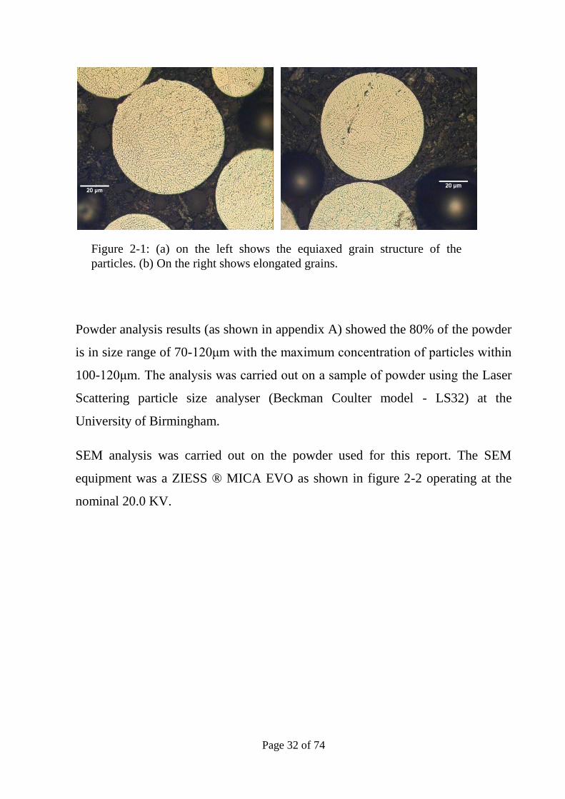
Figure 2-1 shows the PREP® powder that was used in this study. From
microscopically evaluation of the powder as shown in figures 2-1(a & b) it can be
seen that particles tend to have elongated grain structure and it can be concluded
that grains are elongated at the preferred cooling direction during solidification.
The equiaxed grains as seen in figure 2-1b can be attributed to the plane of view
and can be attributed to the elongated grains as seen in figure 2-1a which have
been cut in the direction normal to the growth direction.
Page 32 of 74
Powder analysis results (as shown in appendix A) showed the 80% of the powder
is in size range of 70-120μm with the maximum concentration of particles within
100-120μm. The analysis was carried out on a sample of powder using the Laser
Scattering particle size analyser (Beckman Coulter model - LS32) at the
University of Birmingham.
SEM analysis was carried out on the powder used for this report. The SEM
equipment was a ZIESS ® MICA EVO as shown in figure 2-2 operating at the
nominal 20.0 KV.
Figure 2-1: (a) on the left shows the equiaxed grain structure of the
particles. (b) On the right shows elongated grains.

Page 33 of 74
The SEM analysis of the powder showed the particles were solidified without
segregation as shown in figure 2-3. The images showed impressions on the
particles, which can be the result of the particles impacts during solidification.
Figure 2-3: Backscattered electron
micrograph of the same particle. The image
shows grain boundaries
Figure 2-2: SEM equipment used for this report.
Picture courtesy of Messier-Dowty Ltd.

Page 34 of 74
SEM analysis also showed that the particles are individual without satellites. This
is shown in figure 2-4. Further analysis of the powder used in this study is given
in Appendix A. A number of broken particles could be seen in the image that can
be attributed to the fact that the powder had been used in the past and was
recycled. The SEM results were comparable with those reported by other studies.
[32]
2.3 Direct Laser Fabrication
For the efficient application of DLF, it is paramount that all important process
parameters that could potentially affect the DLF process outcome be identified
and the level of sensitivity of the operating conditions to these process parameters
to be characterised.
Figure 2-4: SEM Image of Ti-5553 powder
used in this study. The image shows the
particles are highly spherical and very fine
surface.

Page 35 of 74
Following the review of the previous work on DLF process as described in the
literature review section, it has been concluded that the main parameters affecting
the outcome of DLF process with a constant “Z” value are: 1) Laser Power, 2)
Powder Feed Rate and 3) Scanning Speed.
In the present work, a TRUMPF VFA 600 CO2 laser unit with power output 0 -
2000Watts and a Sulzer Metco type 9MPE closed loop powder feed unit with
capacity of 1-100gr/min as shown in figure 2-6 was used. A “NUM 1060M”
CNC unit is used to control the workstation and the laser beam movement. Figure
2-5 is the actual image of the DLF equipment used in this study. The laser beam
is directed to the deposition region using a 5-inch focal length convex lens. The
powder is injected through a 3-beam nozzle directly into the focused laser beam
and the laser delivery column and powder nozzle move as an integral unit. An
argon gas jet, coaxial with the beam axis, was used to shield the melt pool from
oxidation. During the laser fabrication process the shielding gas pressure was
kept constant.
The laser spot size at the focal point was 3½ mm dot and each pass had an
overlap of 1½ mm with the previous pass. Other operating parameters were
adjusted accordingly as described in section 2.3. Figure 2-6 shows the 3-beam
nozzle as used in this experiment.
Figure 2-5: TRUMPF
VFA 600 used in the
present study. The
instrument consists of the
laser head and the nozzle
attached to a CNC head
enclosed in the chamber
and the controller unit
with the peripheral
hardware for producing
the deposition program
and tool path.

Page 36 of 74
2.4 Preliminary Studies
In order to better understand and investigate the effects of processing parameters
of the microstructure and mechanical properties of the DLF produced structures,
experiments were designed using Factorial Experimental methodology.
A Factorial Design looks at the effects of varying the levels of different factors
that would affect the process output. Each complete experiment or replication of
the experiment accounts for all the possible combinations of the varying levels
of those factors. Once implemented satisfactorily, the Factorial Design ensures
that the maximum amount of data on the effect on the process output has been
achieved through the minimum number of experimental runs.
For example, if the effects of two factors X and Y on the output of a process are
investigated, and X has 3 levels of intensity (i.e. Low, Medium, and High
presence) while Y has 2 levels (Low and High), then only 6 treatment
combinations runs are required to complete the experiment, covering the process
output for each of the combinations:
Low X-Low Y,
Low X-High Y,
Medium X-Low Y,
Medium X-High Y,
High X-Low Y,
High X-High Y
B
C
Z-axis Figure 2-6: The 3-beam
nozzle used for this
experiment. Figure on
the right is magnified to
show the actual nozzle
tip. Picture courtesy of
the University of
Birmingham, School of
Metallurgy & Materials.

Page 37 of 74
In this research the factors as described earlier were considered as: 1) Laser
Power, 2) Powder feed rate and 3) Scanning speed. For each factor (variable) 3
levels have been considered: Low, Medium and High. The basic concept of
design of experiment using Factorial Experiments methodology would result in
27 experiments
Prior studies carried out in 2010 at the University of Birmingham on Ti-5553 on
behalf of Messier-Dowty Ltd had suggested a selection of process parameters
which could produce an acceptable microstructure. These parameters have been
considered as the Medium values for this study. Table 2-1 is the actual matrix
which indicates the combination of the tests which have been carried out:
Factor 1:
Laser Power
Factor 2: Powder
feed
Factor 3: Scanning
speed
Test
Reference
Low: 20% Low: 5 g/min Low: 600 mm/min Sample 1
Low: 20% Low: 5 g/min Medium: 800 mm/min Sample 2
Low: 20% Low: 5 g/min High: 1000 mm/min Sample 3
Low: 20% Medium: 7 g/min Low: 600 mm/min Sample 4
Low: 20% Medium: 7 g/min Medium: 800 mm/min Sample 5
Low: 20% Medium: 7 g/min High: 1000 mm/min Sample 6
Low: 20% High: 9 g/min Low: 600 mm/min Sample 7
Low: 20% High: 9 g/min Medium: 800 mm/min Sample 8
Low: 20% High: 9 g/min High: 1000 mm/min Sample 9
Medium: 45% Low: 5 g/min Low: 600 mm/min Sample 10
Medium: 45% Low: 5 g/min Medium: 800 mm/min Sample 11
Medium: 45% Low: 5 g/min High: 1000 mm/min Sample 12
Medium: 45% Medium: 7 g/min Low: 600 mm/min Sample 13
Medium: 45% Medium: 7 g/min Medium: 800 mm/min Sample 14
Medium: 45% Medium: 7 g/min High: 1000 mm/min Sample 15
Medium: 45% High: 9 g/min Low: 600 mm/min Sample 16
Medium: 45% High: 9 g/min Medium: 800 mm/min Sample 17
Medium: 45% High: 9 g/min High: 1000 mm/min Sample18

Page 38 of 74
High: 65% Low: 5 g/min Low: 600 mm/min Sample 19
High: 65% Low: 5 g/min Medium: 800 mm/min Sample 20
High: 65% Low: 5 g/min High: 1000 mm/min Sample 21
High: 65% Medium: 7 g/min Low: 600 mm/min Sample 22
High: 65% Medium: 7 g/min Medium: 800 mm/min Sample 23
High: 65% Medium: 7 g/min High: 1000 mm/min Sample 24
High: 65% High: 9 g/min Low: 600 mm/min Sample 25
High: 65% High: 9 g/min Medium: 800 mm/min Sample 26
High: 65% High: 9 g/min High: 1000 mm/min Sample 27
2.4.1 Stage 1: Ti5553 on Ti6Al-4V substrate
At the first stage, Ti-5553 powder was deposited on Ti-6Al-4V substrate due to
unavailability of appropriate Ti-5553 substrate. Ti-5553 substrate were later
made available and used as described in section 2.5.
At this first stage the following parameters were considered as shown in table 2-
2:
Factor 1:
Laser Power
Factor 2:
Powder feed
Factor 3:
Scanning speed
Test Reference
High: 65%
(Average:
1290 W)
1168-1460 W
1.01 ms
Medium: 7
g/min – 3
RPM
High: 1000
mm/min
H.M.H
High: 65% Medium: 7
g/min
Low: 600
mm/min
H.M.L
High: 65% Medium: 7
g/min
Medium: 800
mm/min
H.M.M
Medium: 45%
(Average: 890
Medium: 7
g/min
Low: 600
mm/min
M.M.L
Table 2-1: The experimental program developed
based on Factorial Experiment Design methodology.

Page 39 of 74
w) 759 - 995
Medium: 45% High: 9
g/min
Low: 600
mm/min
M.H.L
Prior to start the process, the powder container was completely disassembled and
thoroughly cleaned to remove the traces of the previous powder used. The
container was then put back together and filled with Ti-5553 powder. In order to
ensure all traces of the previous powder had been removed from the laser system,
a burn out cycle was applied for a number of times and the results were analysed
until the particle analysis system showed no trace of the previous powder.
The results of this stage are subsequently described and discussed in Section 3 of
this report. It must be noted that the substrates were in form of strips of Ti-6Al-
4V wit approximate size of 100mm X 40 mm. Samples were clamped onto the
machine table under a sealed bag filled with Argon as the protective medium.
Deposition process only started when the oxygen content inside the bag had
reached below 5 ppm. Samples were produced in form of cubes with 20mm X
20mm X 20mm.
2.4.2 Stage 2: Ti5553 on Ti-5553 substrate
As mentioned earlier, at the initial test phase, a limited amount of PREP Ti-5553
powder was available for experiments. Due to the nature of the Ti-5553, the lead
time for preparation of the powder is lengthy. Nonetheless further tests were
continued once adequate amount of PREP Ti-5553 as well as appropriate
substrates (Ti-5553 substrate) were made available. Ti-5553 plates were used as
substrates as shown in figure 2-5. Similarly 20mm X 20mm cubes were deposited
Table 2-2: The first stage deposition was carried out
using Ti-5553 powder and Ti-6Al-4V substrate.
Each sample is identified with the applicable
parameters setting.

Page 40 of 74
on these substrates in pre-defined locations as shown in the figure 2-7. .
Substrates were cleaned and degreased with Acetone and then placed on the laser
bed and fixed in position in order to minimise the distortion during processing. In
order to avoid oxidation, the laser bed was then sealed and bagged off in order to
create a protective atmosphere. The created chamber was then purged with Argon
in order to reduce the Oxygen content below 5 PPM. The bead size was kept at
2.0 mm. The bead size was chosen in order to produce an acceptable build rate in
a timely manner. The produced test samples are described and analysed in
Section 3 of this report.
1
2
3
4
5
6
7
8
9
Figure 2-7: Ti-5553 substrates were prepared and clamped ready for
sample deposition. Samples were deposited on the locations predefined as
shown in this picture.

Page 41 of 74
2.5 Optical microscopic evaluation
Once the DLF process was completed and the samples were produced, samples
were measured for physical dimensions and suitable samples were selected.
Select samples are identified in section 3 of this report.
The samples were sectioned off and polished and prepared for micro-analysis.
The polishing process was carried out using an initial polishing using 400, 800,
1200 and 2500 mesh polishing pads. After this, samples were further polished
using 3μ and 1μ diamond suspension and appropriate polishing pads.
Microstructural analyses were carried out using a Leica ™ optical microscope
capability of 100X, 200X 500X & 1000X and Omnimet® image analysis
software. The selected samples were viewed initially in unetched condition in
order to detect any porosity within the deposition layers and then etched with
Kroll’s etchant.
2.5.1 Image analysis on micro-sections
In order to establish the volume fraction of precipitated alpha phase within the
beta matrix, a contrast separation technique was used. The contrast thresholds on
software Omnimet ® could be comfortably set to highlight the alpha phase on
both base and deposition samples. The analysis results are shown in Section 3.
For the samples to be viewed under optical microscope, once cut and mounted,
the surface was prepared using 400, 800, 1200 and 1200 grade wet and dry
rotating polish discs. The samples were further polished using 9µ and 3µ
diamond polish.
To evaluate the microstructure of the samples, prepared samples were etched
using Kroll’s reagent. The etchant was made fresh each time the sample required
etching. The typical chemical composition of the Kroll’s reagent is 100ml water,
1-3ml Hydrofluoric Acid and 2-6ml nitric acid.

Page 42 of 74
2.6 Mechanical tests on sectioned samples
Micro-hardness tests and tensile testing were carried out on the samples to
establish the mechanical properties of the samples under various conditions as
described in section 3. Details of these experiments are explained below.
2.6.1 Micro-hardness testing on deposited samples
Following the microscopic evaluation of the samples, sectioned off samples were
subject to micro-hardness testing as described here.
Micro-hardness tests were carried out on the substrate and the deposited layers
longitudinally and transverse as shown in figure 2-6 to establish the variation of
hardness within the deposit and also for comparison purposes between the
hardness of the base material away from the heat zone in contrast with the
hardness of the heat affected zone. A Mitutoya microhardness tester with a load
range of 3Kg was used for the hardness testing of the sample.
The hardness readings were taken from the base material away from heat affected
zone, shown as zone (1) on figure 2-8 towards the deposition and including the
HAZ.
Dep
osi
tio
n d
irec
tion
Z
on
e 1
Zo
ne
2 Figure 2-8: Hardness tests
were taken as shown on
this picture. Hardness
tests were taken 2.0 mm
apart. Each series were
taken at 3.0mm above the
previous set of readings.

Page 43 of 74
2.6.2 Tensile test
Tensile tests were carried out to establish the mechanical properties of deposited
material. For this purpose, test blocks were deposited and tensile test samples
were extracted from those cubes. Test blocks were produced for both transverse
and longitudinal testing directions. Figure 2-9 illustrates the test blocks that have
been fabricated so the tensile test pieces can be extracted.
Test pieces were cut through the test blocks with an initial diameter of 8mm
using Agie Charmilles Wire-Erosion equipment. Longitudinal tensile test pieces
were extracted parallel to “Z” direction and Transverse test pieces were extracted
in “Y” direction. Test pieces were initially produced using the wire-erosion
machine and then machined off to the final dimension. Those samples that were
subject to further heat treatment, were machined off after the relevant heat
treatment cycles as described in section 3.6.1 & 3.6.2 of this report were
completed. Round test pieces were machined off to meet the requirements of
ASTM E8 and Messier-Dowty PCS 1003 [36] as per drawing number
100028955, with a gauge diameter of 3.96mm and the overall length of 60mm.
Drawing for this test piece is available in PCS1003 [36].
Transverse
samples
Longitudinal
samples
Figure 2-9: Illustration of the test blocks made for tensile
testing. (Side and Top views) Two blocks were fabricated to
produce tensile test pieces. The block on the right was used to
extract vertical (longitudinal) test pieces and the block on the
left was used for vertical (Transverse) test pieces. 8mm
diameter test pieces were cut using wire-cut equipment.

Page 44 of 74
Machined test pieces were then tested using a 100KN Denison-Mayes tensile
tester with 0-25 mm extensometer in accordance with ASTM E8. The tensile
tester is equipped with rate controller and the Stress/Strain curve was drawn
automatically. Further analyses are described in section 3 of this report.
The actual tensile test results are shown in Appendix C.

Page 45 of 74
3 Process Analysis and Discussion
3.1 DLF of Ti-5553
This initial study was arranged in order to eliminate the combination of the test
parameters which would produce unacceptable test results. The purpose of this
study was to identify the acceptable processing parameters for further research.
At this stage, due to unavailability of Ti-5553 substrates, Ti-6Al-4V substrates
were used. Once the substrates were clamped on the work table, the entire setup
was shielded by the protective bag filled with Argon gas to remove any traces of
Oxygen.
DLF machine was setup to produce 20mm X 20mm X20mm cubic samples as per
table 3-1 settings. The setting parameters were selected to represent the possible
extreme conditions for each setup possibility.
Sample ID Factor 1: Laser Power Factor 2:
Powder feed
Factor 3:
Scanning speed
HMH High: 65% (Average: 1290
W) 1168-1460 W
Medium: 7
g/min
High: 1000
mm/min
HML High: 65% Medium: 7
g/min
Low: 600
mm/min
HMM High: 65% Medium: 7
g/min
Medium: 800
mm/min
MML Medium: 45% (Average: 890
w) 759 - 995
Medium: 7
g/min
Low: 600
mm/min
MHL Medium: 45% High: 9
g/min
Low: 600
mm/min
Table 3-1: The first 5 samples were deposited on the Ti-
6-4 substrate due to unavailability of the T-5553
substrate.

Page 46 of 74
Following the deposition stage, table 3-2 shows the outcome of the first series of
fabrication on the Ti 6Al-4V substrates.
Sample ID Deposition height achieved Result Considered
further?
HMH 6.6mm after 20mm
deposition
Cube 1 - Failure No
HMM 13mm after 20mm of
deposition
Cube 3: Height low No
HML 20mm after 20mm
deposition
Acceptable Yes
MML 10m after 20mm of
deposition
Cube 4: Height low No
MHL 20mm after 20mm of
deposition
Cube 5 Yes
The height of the samples was measured using a calibrated 0-200mm Mitutoyo caliper to an
accuracy of 0.01mm. The heights were measured from the highest point of the built to the top
surface of the substrate. The measuring method was repeated throughout the project for all
samples.
3.2 Observation after the first DLF stage:
This section only describes the observations and evaluation of the successful and
acceptable samples following the deposition stage.
Sample HML: The sample was considered as a success. The actual height
of 20 mm was correct compared to the theoretical height of 20 mm. The
sample was considered for metallographic evaluation.
The sample was considered successful with some drawbacks as described
below:
Table 3-2: The first deposition stage carried out using Ti-
5553 powder on Ti 6Al-4V.

Page 47 of 74
Due to the restriction on the machine bed, inadequate clamping was
applied to the base material. As a result, significant distortion was
developed on the base metal. Figure 3-1 shows the distortion of the
sectioned off sample.
This issue highlights the importance of adequately holding down the substrates
during the deposition stage.
3.3 Ti-5553 deposition of Ti-5553 substrate:
As mentioned earlier, at the initial test phase, a limited amount of PREP Ti-5553
powder was available for experiments. Due to the nature of the Ti-5553, the lead
time for preparation of the powder is lengthy. Nonetheless further tests were
continued once adequate amount of PREP Ti-5553 as well as appropriate
substrates (Ti-5553 substrate) were made available. Ti-5553 plates were used as
substrates as shown in figure 3-2. Similarly 20mm X 20mm cubes were deposited
on the substrates in pre-defined locations as shown in the figure 2-7.
As described in section 2, the experimental program was defined in table 2-1.
Starting from sample LLL (S1), figure 3-2 shows that the produced cube did not
adhere to the substrate. This is due to inadequate heat input into the substrate. As
the result, the surface of the substrate was not melted. Subsequently all
Figure 3-1: The
distortion on the
base-metal due to
inadequate clamping
on the sample. This
deformation shows
the importance of
clamping down the
substrate prior to
deposition.

Page 48 of 74
experiments with the laser power set as Low (S1-S9) was cancelled and
considered as invalid.
Deposition on Ti-5553 substrates was carried out as summarised in table 3-3.
Each cube was deposited separately before the nozzle moved to the next
deposition location.
Sample ID Deposition height achieved Result Considered
further?
M.L.L (Sample 10) 9.3mm after 20mm
deposition
Unacceptable No
M.L.M (Sample
11)
4.0mm after 20mm
deposition
Unacceptable No
M.M.L (Sample
13)
10mm after 20mm
deposition
Unacceptable No
M.H.L (Sample
16)
20mm after 20mm
deposition
Acceptable Yes
M.H.M (Sample
17)
10mm after 20mm
deposition
Unacceptable No
H.L.L (Sample 19) 10mm after 20mm
deposition
Unacceptable No
H.M.L (Sample
22)
20mm after 20mm
deposition
Acceptable Yes
H.M.M (Sample 13mm after 20mm Unacceptable No
Figure 3-2: The cube is detached
from the surface. Further visual
examination showed no melting
has occurred on the surface of the
substrate at 20% laser power. All
tests with low (20%) laser power
were subsequently cancelled and
deleted from the test program. 20 mm

Page 49 of 74
23) deposition
H.M.H (Sample
24)
6.6mm after 20mm
deposition
Unacceptable No
H.H.L (Sample 25) 22.5mm after 20mm
deposition
Acceptable Yes
H.H.H (Sample
27)
22.5mm after 20mm of
deposition
Acceptable Yes
3.4 Dimensional evaluations and analysis:
Following the completion of the deposition of all above samples, dimensional
measurements were carried out to establish the correlation between the
processing parameters and the height of deposition. For this purpose, samples
were sectioned through from the highest point and the distance between the
highest point of the build to the bottom face of the substrate were measured using
a calibrated 0-200mm Mitutoyo calliper with an accuracy of 0.01mm. This
method has been used on all samples.
Since the lowest laser power did not produce enough heat to melt the surface of
the substrate, the experiments stated with 2 laser settings: Medium @ 45% of the
power with an average of 890 Watts and High @ 60% of the maximum output
with an average of 1460 Watts. Data gathered and shown in figure 3-3 for laser
power setting at 45% and 3-4 for the laser power set at 60%.
Table 3-3: Deposited samples were made using 3 levels of each processing
parameter and the results of height achieved after 20 mm nominal
deposition layers. Only those samples that achieved the correct height have
been considered for further analysis.

Page 50 of 74
Figure 3-3: The graph shows the correlation between
the Final achieved height as the result of Feed Rate and
Scan Speed with a constant laser power of 45%.
Figure 3-4: The graph shows the correlation between the
Final achieved height as the result of Feed Rate and Scan
Speed with a constant laser power of 60%.

Page 51 of 74
It must be noted that based on the extrapolation of each unacceptable condition,
other combination of the processing parameters where based on the information
from the literature review or extrapolation of the result would predict
unacceptable results were taken off the program and not included.
Further evaluations were carried out on the acceptable samples # 16, 22, 25 and
27 for the level of spattering around the deposition layers, the geometry of the
build, defect build-up during deposition and processing time. Processing
parameters H.H.H (Sample #27) was considered the satisfactory combination of
the parameters.
3.5 Microscopic Evaluation:
The selected sample was sectioned off and prepared as described in section 2.
The prepared section was viewed for porosity and other manufacturing defects
within the layers in unetched condition, and then it was etched for micro-
structural analysis.
3.5.1 Microscopic analysis of unetched sample:
One of the important aspects of this research is to establish the level of porosity
within the build and even more significantly, within the interface of the
deposition and the substrate. Microscopic evaluation of the deposited layers as
shown in figure 3-5 show no porosity contained within the microstructure.
Further analysis of the microstructure also showed no inter-layers defects such as
lack of fusion or lamination.

Page 52 of 74
Further analyses were carried out to establish if any defects have been formed
between the substrate and the deposited layers. Figure 3-6 shows the unetched
section of the interface between the substrate and the deposition. As shown in this
image the interface also appears without any defects. The Heat Affected Zone can
be seen due to the different crystallographic arrangements of the grains in this
area and the adjacent areas.
Figure 3-5: Micro-section of deposited layers of Ti-5553. No
porosity or interlayer defects can be seen. The microstructure
appeared solid and fully integrated without any interlayer defects.
Dep
osi
tio
n d
irec
tion

Page 53 of 74
Comparisons were made between the micro section of the substrate and the
deposition in order to highlight any immediate differences between the two. In
the unetched condition, it is not possible to observe the exact microstructure
including the grain boundaries and α and β phases. However at the higher
magnifications, it was noted that Ti-5553 substrate showed a considerable
amount of precipitates with smooth edges as shown in figure 3-7 when compared
to what seemed to be precipitates in as-deposit with needle type precipitates
shown in figure 3-8, all appeared white in a dark background.
Substrate
Deposition
structure
Dep
osi
tio
n d
irec
tio
n
Interface
Figure 3-6: The image taken from the interface between the
substrate (at the bottom) and the deposited layers (at the top).
Similar to the actual deposit, here also no sign of porosity or
other defects can been seen.
20 µm
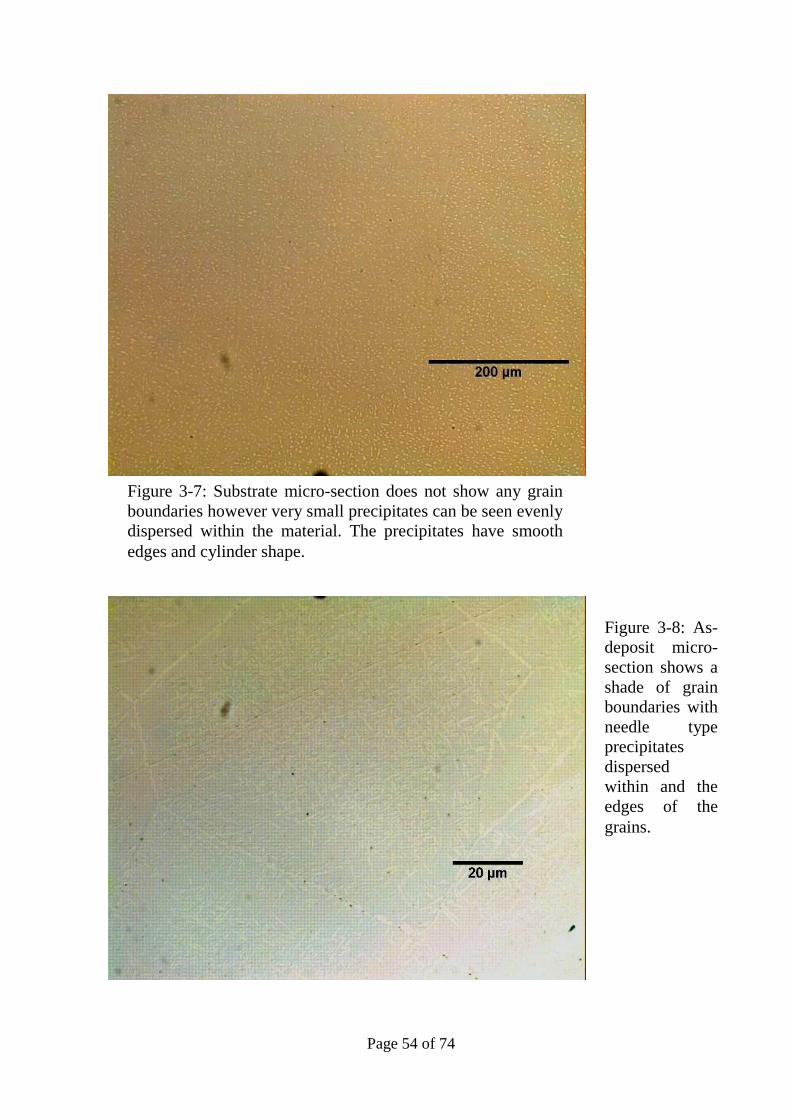
Page 54 of 74
Figure 3-7: Substrate micro-section does not show any grain
boundaries however very small precipitates can be seen evenly
dispersed within the material. The precipitates have smooth
edges and cylinder shape.
Figure 3-8: As-
deposit micro-
section shows a
shade of grain
boundaries with
needle type
precipitates
dispersed
within and the
edges of the
grains.

Page 55 of 74
3.5.2 Microstructural analysis of DLF samples – Etched
Following the visual and micro-evaluation in unetched condition, the samples
were etched with Kroll’s etchant and dried off. The microstructural analysis was
carried out on both categories of test pieces: Ti-5553 deposition on Ti-6Al-4V
and Ti-555-3 deposition on Ti-5553 substrate.
3.5.2.a – Microstructural evaluation of Ti-5553 deposition on Ti-6Al-4V
substrate:
Figure 3-9 shows the microstructure of the Ti 6Al-4V substrate in contrast with
the microstructure of the deposited Ti-5553 taken from sample HML during the
first stage of the experiment.
As mentioned before, Ti-6Al-4V has been used as a substrate since the
appropriate substrate was not available. The metallurgy of this alloy is not
reviewed and researched in this report. The figure illustrates the Heat Affected
zone and the microstructural changes due to the heat input form the process and
the boundary between the deposition and the substrate.
Picture 3-9: (a)
Deposition layers of Ti-
5553 powder, (b)
deposition interface, (c)
Heat affected zone
which has been re-
crystallised & (d)
unaffected base metal.
a
b
c
d
Dep
osi
tio
n d
irec
tion

Page 56 of 74
3.4.2.b - Microstructural evaluation of Ti-5553 deposition on Ti-5553
substrate:
Ti-5553 deposition on Ti-5553 substrate was also subject to metallographic
evaluation after etching. Figures 3-10 and 3-11 show the grain growth throughout
the deposition as moving away from the deposition/substrate interface. This
growth is associated with the increase in residual heat build-up as deposition
progresses. The grains measured within 250-600µm and appear as equiaxed.
Ti-5553 substrate as shown in figure 3-12 contains significant volume of α-phase
precipitated during the thermal processes at the forging stage and subsequent to
the thermal treatments at the later stages during the manufacture. In contrast, as
illustrated by figures 3-10 and 3-11, the as-deposited microstructure contains
100% β-grains and no chance has been given to α-phase for precipitation.
Figure 3-10: Ti-5553 deposited
layers adjacent to the interface.
The equiaxed grain sizes vary
between 250-600µm. The grain
sizes increase with the progress of
the build.
Dep
osi
tio
n d
irec
tion
400µm
Dep
osi
tio
n
Figure 3-11: Ti-5553 deposited
layers at the top layers. The
grains have grown considerably
and now measure between 400-
1000µm.

Page 57 of 74
The substrate (as shown in figure 3-12) contains aged Beta matrix with alpha
precipitations. There are 2 categories of the precipitated alpha: Primary &
Secondary:
Primary alpha phase has been precipitated during the forging stage. The
secondary alpha phase is precipitated during the ageing cycle. The secondary
alpha precipitates are extremely fine within the beta matrix. The ageing cycle for
this material includes heating the material at temperature 50°C below the beta-
transus (β-t) temperature for a period of 8 hours and air cooled to room
temperature. This heat treatment cycle has been established by the material
specification and the temperature has been specified to be below the beta transus
in order to produce as much secondary alpha phase as possible without
undesirable growth of beta grains. As illustrated by the figures above, there is a
significant difference between the as-deposit structure of the deposited layers and
the heat treated substrate.
20 μm
Figure 3-12: The image taken
from the Ti-5553 substrate.
The microstructure contains
β-matrix with α-phase
precipitated within the
grains. Large β grains cannot
be easily separated in the
background.

Page 58 of 74
3.5.3 Mechanical tests on as deposit samples:
Mechanical tests including room temperature tensile testing and micro hardness
testing were carried out on the test pieces. Tensile tests were carried out on the
samples extracted from the specifically fabricated blocks, but the hardness tests
were carried out on the actual test samples.
3.5.3.a – Micro-hardness testing:
Micro-hardness tests were carried out on the substrate and the deposited layers
(longitudinally) and transverse to establish the variation of hardness within the
deposition and also for comparison purposes between the hardness of the base
material away from the heat zone in contrast with the hardness of the heat
affected zone.
The results on figure 3-13 show that the hardness has decreased with the progress
of the build. Such hardness results variations within the build confirm the
increase in the grain size increase as shown previously. This effect has been
attributed towards the residual heat from the deposition of each next layer of
build.
Figure 3-13: Hardness results of the deposition. The readings are taken from the bottom of
the build, near to the HAZ towards the top of the build. The results show hardness decrease
as the height of the build increases. Vickers hardness test, HV3Kg.
Build Direction
H
ard
nes
s re
sult
s -
HV
3.0
Kg

Page 59 of 74
The hardness results on the substrate as plotted in the figure 3-14 show that the
hardness has dropped below the HAZ and would increase when measure away
from the HAZ.
3.5.3.b – Tensile testing in as-deposit condition:
Tensile tests were carried out also showed that the minimum mechanical
requirements have not been achieved. Table 3-4 show the tensile test results for
both longitudinal and transverse test pieces in as-deposit condition.
Sample
#
Location Condition 0.2% P.S.
(MPa)
achieved
0.2%P.S.
Standard
UTS
achieved
(MPa)
UTS
Standard
(MPa)
Sample
1 Longitudinal As deposit 994.9
1170
minimum 1070
1240
minimum
Sample
2 Transverse As deposit 1035
1170
minimum 1190
1240
minimum
Figure 3-14: Hardness variations from the bottom of the substrate
towards the HAZ. Hardness readings taken using HV 3Kg.
H
ard
nes
s re
sult
s -
HV
3.0
Kg
Movement of head

Page 60 of 74
3.6 Microstructural Improvement
As shown above, the as-cast microstructure showed significantly different
structure to the base material. No evidence of α-phase precipitation could be seen
in the samples. Tensile test results and microstructure analysis of the samples
confirm the previous information within the literature. As reported by the
reviewed literatures [7, 8, 9], heat treatment cycles are required to facilitate
precipitation of α-phase within the β-matrix.
3.6.1 Heat treatment of Deposited Ti-5553 - Ageing cycle
The first heat treatment cycle considered in this study was an ageing cycle. As
per Messier-Dowty material specification [25] the recommended ageing cycle for
this material is soaking at 600ºC for 8 hours followed by air cool to room
temperature. Following this heat treatment cycle, the microstructure showed
some precipitated α-phase within aged β-grains as shown in figure 3-15.

Page 61 of 74
The tensile test result for the aged samples showed a marginal improvement in
the mechanical properties. The Proof Stress had increased to 1160 MPa, still
below the minimum requirement of 1170 MPa, but the ductility has not
improved. The test piece failed with almost 4% elongation compared to minimum
6% elongation required on longitudinal test pieces.
3.6.2 Further heat treatments – Solution treatment and Ageing
Based on the metallographic evaluation results and also the mechanical testing
results, ageing cycle will not develop adequate α-precipitates. As the result and as
Dep
osi
tion
dir
ecti
on
Figure 3-15: Optical micrograph of aged sample. The precipitated
alpha is shown in white within the dark beta background. The alpha
precipitates are about 1-2 micron in length. The precipitation is not
uniform and patchy within the microstructure. In general where,
precipitation occurred it has developed Widmanstatten morphology.

Page 62 of 74
recommended by the published literatures, solution treatment and ageing cycles
were investigated.
For this purpose, solution treatment at 50ºC below the β-transus temperature was
studied. This temperature was selected to ensure no β transformation happens
within the substrate. Such transformations would greatly affect the properties of
substrate. Slow cooling is required for the alpha phase to precipitate from the beta
matrix. Ageing temperatures of 500°C, 550°C & 600°C were selected and the test
pieces were aged for 1 hour at temperature. The test pieces were then subject to
tensile testing to select the condition with the most desirable properties for further
evaluation. The result of mechanical testing showed that ageing cycle at 600°C
had produced the nearest mechanical properties to those of the material
specification. The mechanical test results for the sample solution treated at 900°C
and aged at 600°C are summarised in table 3-5.
Figure 3-16 shows the micro-section of the Solution treat at 900°C and Aged at
600°C sample after polishing and prior to etch. The micro-section appears to be
plain without any precipitates in contrast to the micro-section from the substrate
as shown in figure 3-17. Considering the fact that the substrate has been subject
to a number of Solution treatment and Ageing cycles, the potential growth of the
precipitates is expected.
Sample # Condition 0.2% P.S.
(MPa)
achieved
0.2%P.S.
Standard
UTS
achieved
(MPa)
UTS
Standard
(MPa)
Sample 8
Solution Treated @
900°C& aged @ 600°C 1163 MPa
1170
minimum 1256 MPa
1240
minimum
Samples 9
(Repeated)
Solution Treated @
900°C& aged @ 600°C 1180 MPa
1170
minimum 1266 MPa
1240
minimum
Table 3-5: Mechanical test results of the solution treated and aged samples.
The process was repeated to ensure the repeatability of the results.

Page 63 of 74
Figure 3-16: The micro-section from the deposition shows
plain β – matrix with no α-precipitation.
Figure 3-17: In contrast with the deposition layers, the micro-
section from the substrate already shows signs of precipitation.
This will be confirmed when the samples has been etched and
grains and precipitates are revealed.
Dep
osi
tio
n d
irec
tion
D
epo
siti
on d
irec
tion

Page 64 of 74
The etched micro-section of both the substrate (figure 3-18) and deposition
(figure 3-19) samples show that significant precipitation of α-phase has occurred
within the aged β-matrix.
The α-precipitates in substrate shown in white are in 2 main categories: Primary α
that have deposited during the first heat treatment cycle at forging stage and
Secondary α phase precipitated during the final heat treatment. However due to
the repeat of the heat treatment it is anticipated that the primary α precipitates
have increased in size and also developed more spherical shape.
Figure 3-18: Optical
micrograph of base
material. Primary
alpha in clusters
precipitated at the
forging stage with
extremely fine
secondary alpha
within Beta
background
precipitated during
the ageing stage.
Etched in Krolls.
Primary alpha
Fine secondary
alpha

Page 65 of 74
Deposition sample microstructure shows needle shape α-phase precipitation
spread within the aged β matrix. The α-precipitates measure between 3-6µm in
size. Precipitation also has occurred along the grain boundaries, which as
described previously, is an undesirable phenomenon and would create weakness
within the structure as the result of the brittleness of α-phase.
3.6.3 Volume fraction analysis of α-phase within β-matrix
Using the image analysis software as described in section 2, volume fraction
analysis was carried out to establish the percentage on α/β phases. The image
analysis results are shown in figure 3-20 for substrate and figure 3-21 for
deposition and the results shown in table 3-5.
Figure 3-19:
Optical micrograph
of deposit at higher
magnification it
can be seen better
that needle type
alpha precipitations
form
Widmanstatten
morphology. The
growth pattern
shows dendritic
growth on
preferred
crystallographic
directions. Etched
in Krolls. 20 µm
Dep
osi
tio
n d
irec
tion

Page 66 of 74
#
The results of the volume fraction analysis as shown graphically and quantified in
table 3-6 suggest that in case of the deposit, the volume of precipitated alpha is
almost twice the volume of primary and secondary precipitated alpha in the base
metal. This suggests that further work can be carried out to optimise the heat
treatment cycles so adequate alpha can be precipitated. Such optimisation can
potentially reduce the heat treatment cycle times.
3.7 Discussion:
The study suggests that the successful DLF depends on 2 main categories of
variables: Processing parameters and Metallurgical aspect of the substrate and
deposition.
Sample tested Measured Area Area Fraction
Substrate 1597.05µm² 10.8 %
Deposition 476.44 µm² 23.5 %
20 µm
Dep
osi
tio
n
dir
ecti
on
20 µm
Dep
osi
tio
n
dir
ecti
on
Figure 3-20: Optical micrograph
of base material. Threshold was
set to separate alpha phase from
the beta matrix. Alpha
precipitates are shown in green.
Figure 3-21: Optical micrograph
of deposit Thresholds were set
to segregate alpha precipitates
in needle shape from the beta
matrix.
Table 3-6: α-phase area fraction analysis results for Substrate
and Deposition.

Page 67 of 74
3.7.1 Processing Parameters
The characterisation results of the samples processed with various processing
parameters proved that in order to achieve the theoretical build height, Scanning
rate, Powder feed rate and the Laser Power must be optimised. Reduction in the
scanning speed would increase the build rate and would result in excessive usage
of the powder. In opposite, increase in the scanning speed, the previous layer is
exposed to the laser power for a shorter time and the overall build rate will be
reduced. Since the “Z” parameter is constant, the distance between the laser focal
point and the last build layer will increase causing the focal spot to be further
away from the build. Once the laser focal point has moved away from the build,
the laser will no longer melt the powder and the powder will free flow.
The powder feed rate would also affect the quality of the deposition. High
powder feed rates, apart from an unnecessary increase in the powder
consumption; will cause the powder to flow back into the nozzle and the laser
head causing defects to be formed within the nozzle, as it was seen during the
deposition of samples in this project. Lower feed rates on the other hand will
result in reduction in deposition rate.
Laser power also affects the deposition results. Inadequate laser power would not
melt the substrate so the deposition will not adhere to the surface. Higher laser
power would result in higher degree of superheat in the molten metal causing
slower cooling rates. However the significance of the laser power effect is on the
morphology of the microstructure. Analysis results as reported by J. Liang in his
PhD thesis [37] proved that increase in laser power would result in the shift of the
morphology from the columnar grains towards equiaxed morphology. However
the morphology of the samples in the present study appeared to be equiaxed.
Optimum processing parameters would ensure defect free deposition to be
produced as required. However it must be noted that the optimisation must be

Page 68 of 74
carried out for each application and processing parameters from one application
can not necessarily be transferred to another application.
3.7.2 Metallurgical aspect
Metallographic studies on the samples showed the microstructure of the as-
deposited samples of Ti-5553 to be of β nature with no precipitated α phase. The
micrographs of the various build heights showed that grains size increase as the
build progresses.
The interface between the substrate and the deposition is clearly defined by the
HAZ. Micro-sections proved that grains sizes immediately after the interface are
significantly smaller size (200-600µm) when compared to the grain sizes in
further distance from the interface (400-1000µm). These results also repeat the
conclusion taken by F.Wang & et al. [29] as discussed earlier in section 1.4.1.
Micro-section of the interface and the deposition layers did not contain any
porosity, although other studies [36] have reported various levels of porosity
within the deposition. The study suggested the lower laser powers would result in
higher volume of porosity, although the study was carried out on Ti-6Al-4V and
not Ti-5553. The powder was not also reported to be PREP® so it may include
inherent porosity, which it was shown earlier in this report that PREP® powder
does not include inherent pores.
Tensile results of as-deposit samples suggest the mechanical properties of the
deposition in this condition to be extremely low. This is also confirmed by the
hardness test readings.
The ageing cycle following the deposition showed some improvement and the
microscopic observations showed a limited volume of α-phase precipitated within
the β-matrix. Tensile properties were also improved but still significantly below
the requirements for Ti-5553 material.

Page 69 of 74
Microscopic evaluations showed that Solution treatment and ageing cycle would
significantly increase the volume fraction of the α-phase within the β-matrix. The
solution treatment in this study was carried out below the β-transus temperature
for the substrate in order to ensure the as-forged condition of the substrate is not
affected by this heat treatment cycle.
The volume fraction of α-phase in deposition appeared to be higher than the
substrate. This can be attributed to the controlled heat treatment cycle and the
forging process for manufacturing the substrate.
Micro-section analysis also showed α-precipitates precipitated along the β grain
boundaries. This is particularly undesirable due to the ductile nature of the α-
phase that would reduce the strength of the material.
The final results were repeatable and were reproduced. The tensile test results
showed significant improvement in the mechanical properties of the deposition.
The results showed that solution treat and aged samples achieve the minimum
U.T.S requirements for Ti-5553, although the proof strength has not successfully
reached the minimum requirements. It must be considered that mechanical
properties referenced in this report are of those which have been produced by
forging process and it is expected to be significantly greater than material
produced through casting processes. In comparison, other studies [19] on DLF of
Ti-6Al-4V have been reported to reach the material specification limits however
due to the limited study on DLF on Ti-5553, the UTS of the solution treat and
aged samples as reported in this report exceed the values published by
J.C.Fanning et al. in his study of DLF of Ti-5553.
3.7.3 Process limitations:
Inherent Process Limitations: One of the major limitations of this technology is
extreme difficulty of the systems to be mobile. In cases where the DLF technique

Page 70 of 74
ought to be used in-situ i.e. in case of ad-hoc repairs, the system is non-flexible
and cannot be moved easily.
Other inherent limitation is the absolute need of protective atmosphere during the
deposition. Experiments proved although protective carrier gas flows through the
nozzles, it does not provide adequate protection of the melting pool. As a result
special protection chambers have to be set up and the oxygen level must be
reduced below 500 PPM to avoid oxidisation during deposition.

Page 71 of 74
4 Conclusion
4.1 Study results
Based on the present study, the following conclusions can be drawn:
Direct Laser Fabrication process was trialled and modified to adopt
Titanium Ti-5553 powder for aircrafts landing gears. The process used the
TRUMPF VFA 600 CO2 laser deposition system at the University of
Birmingham using PREP Ti-5553 powder.
The result utilised 3 processing parameters: Scanning Speed, Laser power
and Powder feed rate. Microstructures analysis showed that the grain
structure is equiaxed as the result of pulsed laser.
The process optimisation results showed that using PREP ® powder and
selecting correct processing parameters will produce microstructures free
from porosity. However the desirable beta matrix with precipitated alpha
cannot be achieved without some form of heat treatment.
The heat treatment cycle must include solution treatment followed by
precipitation stage. The single precipitation stage would not produce the
desirable microstructure and the mechanical properties required.
Tensile test results showed that mechanical properties are uniform and
consistent along the length of the deposition; however these properties vary
through the height of the deposition. Higher layers of deposition show
slightly reduced mechanical properties. This reduction in the properties can
be attributed to the increase in beta grain sizes.

Page 72 of 74
4.2 Limitations:
The limitation during this study can be separated into 2 categories: a) Processing
and b) Metallurgical studies.
a) This study was carried out using Ti-5553 available at the time at the
University of Birmingham. One limitation during the study availability of new
Ti-5553 proved to be of a problem. This was mainly due to the fact that Ti-5553
billets are not readily available to powder manufacturers and therefore long lead
times and also high manufacturing costs are associated with the production of the
powder. This could have an impact on the study if the existing volume of powder
was insufficient for completion of the study.
Other processing limitation during this study was the actual number of variables
or processing parameters studied. For each variable of Laser Power, Scanning
speed and Flow rate the study was focused on the 3 levels of low, medium and
high ensuring that characteristics such as frequency and pulsing method as well
as other processing parameters such as “Z” height were unchanged.
The powder used during the process was PREP® powder which as described in
this study, contains significantly less inherent effects. Due to the unavailability
and the long manufacturing lead time of the Gas atomised powder, this type of
powder was not used during the study.
The number of samples produced for each successful combination of processing
parameters to prove the repeatability of the process were limited.
Also it must be noted that the dimensions of the samples were kept constant at
20mmX20mm X20mm. It has not been studied if longer and/or wider builds
could be successfully produced using the same parameters.

Page 73 of 74
b) The desired microstructures could only be achieved by heat treatment of
deposited structure, but the heat treatment cycles could not be applied in-situ
using the laser system.
4.3 Future work
The research can be continued in future in a path to achieve the following
objectives:
Effects of powder type on the microstructure: Prep® powder was used
during this project which showed no porosity within the build. However it
is expected the level of porosity would increase using gas atomised
powders, as the result of inherent gas within the particles. Further tests and
analysis are required in order to establish the level and effect of porosity on
the mechanical properties.
It is not clear that the optimised processing parameters are independent of
the dimensions of the deposition. Future work is suggested in order to
establish if the same processing parameters would create the same results
at larger dimensions or complex geometries.
Further work is also recommended in developing heat treatment cycles
during deposition process. This can be particularly important when
industrialisation of the DLF process is considered. To the knowledge of the
author, further Hipping processes are currently being researched for DLF’s
parts that could include heat treatment cycles; however the need for
separate heat treatment process after the deposition can potentially limit the
benefits of this technology for in-situ applications.
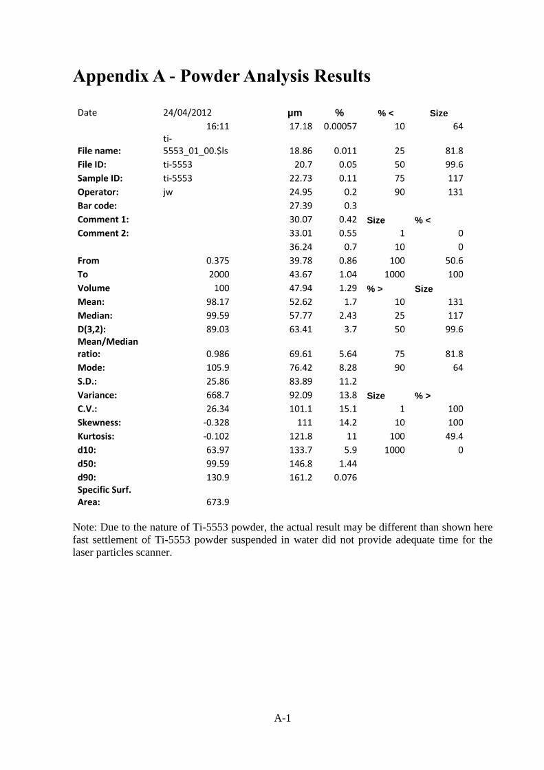
A-1
Appendix A - Powder Analysis Results
Note: Due to the nature of Ti-5553 powder, the actual result may be different than shown here
fast settlement of Ti-5553 powder suspended in water did not provide adequate time for the
laser particles scanner.
Date 24/04/2012 µm % % < Size
16:11 17.18 0.00057 10 64
File name: ti-5553_01_00.$ls 18.86 0.011 25 81.8
File ID: ti-5553 20.7 0.05 50 99.6
Sample ID: ti-5553 22.73 0.11 75 117
Operator: jw 24.95 0.2 90 131
Bar code: 27.39 0.3
Comment 1: 30.07 0.42 Size % <
Comment 2: 33.01 0.55 1 0
36.24 0.7 10 0
From 0.375 39.78 0.86 100 50.6
To 2000 43.67 1.04 1000 100
Volume 100 47.94 1.29 % > Size
Mean: 98.17 52.62 1.7 10 131
Median: 99.59 57.77 2.43 25 117
D(3,2): 89.03 63.41 3.7 50 99.6 Mean/Median ratio: 0.986 69.61 5.64 75 81.8
Mode: 105.9 76.42 8.28 90 64
S.D.: 25.86 83.89 11.2
Variance: 668.7 92.09 13.8 Size % >
C.V.: 26.34 101.1 15.1 1 100
Skewness: -0.328 111 14.2 10 100
Kurtosis: -0.102 121.8 11 100 49.4
d10: 63.97 133.7 5.9 1000 0
d50: 99.59 146.8 1.44
d90: 130.9 161.2 0.076 Specific Surf. Area: 673.9

A-2
Ti5553 powder size distribution
0
2
4
6
8
10
12
14
16
0 50 100 150 200
Particle size (µm)
Vo
lum
e fr
acti
on
(%
)

B-1
Appendix B - Model design
Boeing B787 Truck Beam has been designed and manufactured by Messier-Dowty Ltd
Gloucester. The design utilises a Model Based definition that has been extracted and translated
into Catia® model that can be used by the DLF machine.
The stress design of the truck beam requires the entire part to be manufactured through forging
process. The forged part includes all the lugs as required by the original design. As mentioned
earlier the aim of this study is to establish the possibility of producing those lugs through Laser
Deposition technology on the forged cylinder. The cost analysis (details available at Messier-
Dowty Ltd, not published due to data confidentiality) carried out at Messier-Dowty had shown
the cost of forging complete detailed part is significantly higher than the forging of the main
cylinder without the Lugs.
It must also be noted that the samples in this research were produced on flat surfaces. The
actual application of this technology on the landing gears would require deposition on curved
surface. The deposition model as shown below has been developed to produce the lug as
shown in pictures B2 and B3.
Figures B1-B4: pictures above show the Catia ® model used for the deposition of
the lug. Although the model showed deposition on curved surface, the actual
deposition was carried out on flat substrate as shown below in figures B3 & B4.

C-1
Appendix C - Tensile test results

C-2

C-3

C-4

C-5

C-6

C-7

C-8

C-9

C-10

C-11

References:
[1] International, A., Materials Properties Handbook: Titanium Alloys, ed. R. Boyer, Welsch, G.,
Collings, E.W. 1994.
[2] E. W. Collings,Materials properties handbook: titanium alloys, Section 2.1
[3] J.N. Fridlyander & D.G. Eskin, Advances in Metallic Alloys, Titanium Alloys, Russian
Aircraft and Aerospace applications, Taylor & Francis Group, 2006
[4] Lütjering, G., Williams, J.C., Titanium. 2nd ed. 2007: Springer 442.
[5] S. Ankem, C.A. Greene : Materials Science and Engineering A263 (1999) 127–131
[6] G. Martin et al./ Procedia Engineering 10 (2011) 1803–1808
[7] K.V. SUDHAKAR et al., Department of Metallurgical and Materials Engineering, MONTANA Tech
of the University of MONTANA, BUTTE, MT 59701, USA
[8] N. Stefansson, I. Weiss, A.J. Hutt, P.G. Allen, P.J., in: P.A. Blenkinsop, W.J. Evans, H.M.
Flower (Eds.), Titanium ’95, vol. II, The Institute of Materials, London, 1996, pp. 980–987.
[9] J. Ph. Guibert et al., Les Alliages de Titane Beta, Socie´te´ Franc¸aise de Me´tallurgie et de
Mate´riaux, 1994, pp. 197–204.
[10] R.R. Boyer, R.D. Briggs, J. Mater. Eng. Perform. 14 (2005) 681–685.
[11] N. Clement, A. Lenain, P.J. Journal of Materials Volume 59 (1) (2007) 50–53.
[12] A. Carman et al.. / Materials Science and Engineering A 528 (2011) 1686–1693
[13] Ali Dehghan-Manshadi, Rian J. Dippenaar, Development of α-phase morphologies during
low temperature isothermal heat treatment of α Ti–5Al–5Mo–5V–3Cr alloy, Materials Science
and Engineering ,A 528 (2011) 1833–1839
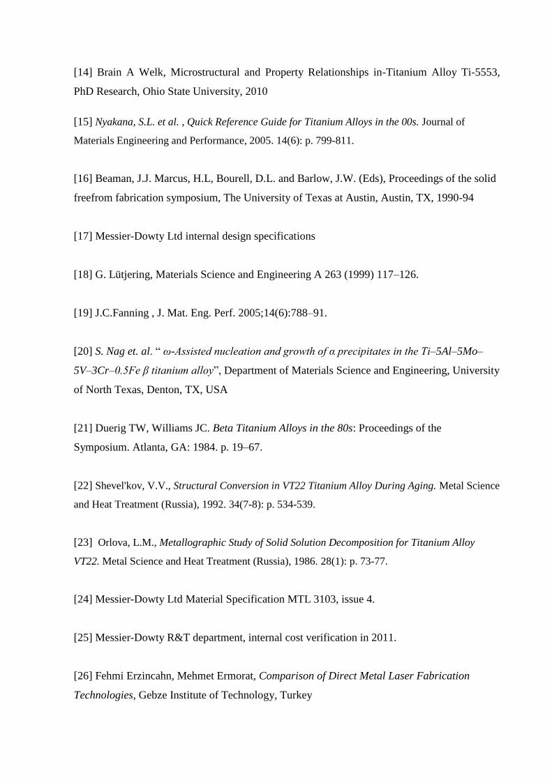
[14] Brain A Welk, Microstructural and Property Relationships in-Titanium Alloy Ti-5553,
PhD Research, Ohio State University, 2010
[15] Nyakana, S.L. et al. , Quick Reference Guide for Titanium Alloys in the 00s. Journal of
Materials Engineering and Performance, 2005. 14(6): p. 799-811.
[16] Beaman, J.J. Marcus, H.L, Bourell, D.L. and Barlow, J.W. (Eds), Proceedings of the solid
freefrom fabrication symposium, The University of Texas at Austin, Austin, TX, 1990-94
[17] Messier-Dowty Ltd internal design specifications
[18] G. Lütjering, Materials Science and Engineering A 263 (1999) 117–126.
[19] J.C.Fanning , J. Mat. Eng. Perf. 2005;14(6):788–91.
[20] S. Nag et. al. “ ω-Assisted nucleation and growth of α precipitates in the Ti–5Al–5Mo–
5V–3Cr–0.5Fe β titanium alloy”, Department of Materials Science and Engineering, University
of North Texas, Denton, TX, USA
[21] Duerig TW, Williams JC. Beta Titanium Alloys in the 80s: Proceedings of the
Symposium. Atlanta, GA: 1984. p. 19–67.
[22] Shevel'kov, V.V., Structural Conversion in VT22 Titanium Alloy During Aging. Metal Science
and Heat Treatment (Russia), 1992. 34(7-8): p. 534-539.
[23] Orlova, L.M., Metallographic Study of Solid Solution Decomposition for Titanium Alloy
VT22. Metal Science and Heat Treatment (Russia), 1986. 28(1): p. 73-77.
[24] Messier-Dowty Ltd Material Specification MTL 3103, issue 4.
[25] Messier-Dowty R&T department, internal cost verification in 2011.
[26] Fehmi Erzincahn, Mehmet Ermorat, Comparison of Direct Metal Laser Fabrication
Technologies, Gebze Institute of Technology, Turkey
[27] Wu, X. (2006) Net Shape Manufacturing of Aeroengine Components. In Cost Effective
Manufacture via Net-Shape Processing (pp. 5-1 – 5-10). Meeting Proceedings RTO-MP-AVT-
139, Paper 5
[28] W.U.H. Syed et al. / Applied Surface Science 247 (2005) 268–276
[29] F. Wang et al., Microstructure study of direct laser fabricated Ti alloys using powder and
wire, Applied Surface Science 253 (2006) 1424–1430
[30] Yuchang Fu et al., A theoretical model for laser and powder particles interaction during
laser cladding. Journal of Materials Processing Technology, Vol 128, Issues 1-3 (2002) 106-
112
[31] X. Wu et al., Microstructures of laser-deposited Ti–6Al–4V / Materials and Design 25
(2004) 137–144
[32] M.N. Ahsan et al., A comparative study of laser direct metal deposition characteristics
using gas and plasma-atomized Ti–6Al–4V powders, Materials Science and Engineering A 528
(2011) 7648– 7657
[33] M.N. Ahsan, C.P. Paul, L.M. Kukreja, A.J. Pinkerton, Journal of Materials Processing
Technology 211 (4) (2011) 602–609.
[34] Yunchang Fu, A.Loredo, B.Martin, A theoretical model for laser and powder particles
interaction during laser cladding, Journal of Materials Processing Technology Vol. 128, Issues
1-3 (2002) 106-112
[35] S.Y. Wen et al. Modeling of coaxial powder flow for the laser direct deposition process /
International Journal of Heat and Mass Transfer 52 (2009) 5867–5877
[36] Messier-Dowty Ltd Specification, Mechanical testing requirements.
[37] Jing Liang, PhD Thesis, University of Birmingham, 2004

[38] P.A. Kobryn & et al. The effect of laser power and traverse speed on Microstructure, porosity
and build height in laser-deposited Ti-6Al-4V, Scripta materialia. 43 (2000) 299–305
[39] Proceedings to ICALEO 2009, Kamran Shah & et al. Parametric study of development of
Inconel-steel functionally graded materials by laser direct metal deposition,
[40] Proceedings to PICALO 2008, M. Guirad & et al. Process Control on Laser Cladding by
Coaxial Vision for Direct Manufacturing of 3D Metallic Structures
Related Documents