School of Aerospace Engineering CERT Prediction of Rotorcraft Noise with A Low-Dispersion Finite Volume Scheme A Thesis Proposal Presented to The Faculty of the Division of Graduate Studies By Gang Wang Advisor: Dr. T. C. Lieuwen

Welcome message from author
This document is posted to help you gain knowledge. Please leave a comment to let me know what you think about it! Share it to your friends and learn new things together.
Transcript

School of Aerospace EngineeringSchool of Aerospace Engineering
CERTCERT
Prediction of Rotorcraft Noise with A Low-Dispersion Finite
Volume SchemeA Thesis Proposal
Presented toThe Faculty of the Division of Graduate Studies
ByGang Wang
Advisor: Dr. T. C. Lieuwen

School of Aerospace EngineeringSchool of Aerospace Engineering
CERTCERT
OUTLINE
Background
Approach
Results
Conclusions
Proposed Work

School of Aerospace EngineeringSchool of Aerospace Engineering
CERTCERT
BACKGROUND
Helicopter has a wide range of military and civil applications.
However, the high noise level associated with it greatly restricts its further applications.

School of Aerospace EngineeringSchool of Aerospace Engineering
CERTCERT
BACKGROUND
Three categories of rotor noiseRotational noiseBroadband noiseImpulsive noise
High Speed Impulsive (HSI) noise Blade Vortex Interaction (BVI) noise

School of Aerospace EngineeringSchool of Aerospace Engineering
CERTCERT
BACKGROUND
High Speed Impulsive noise

School of Aerospace EngineeringSchool of Aerospace Engineering
CERTCERT
BACKGROUND
Blade Vortex Interaction noise

School of Aerospace EngineeringSchool of Aerospace Engineering
CERTCERT
BACKGROUND
Many efforts have been spent on quantifying and minimizing rotorcraft noise.
Three noise prediction techniques:High resolution aerodynamics in the near field
and acoustic analogy for radiation in far fieldHigh resolution aerodynamics in the near field
and Kirchhoff’s formula for radiation in far fieldFully computational aerodynamics and acoustics

School of Aerospace EngineeringSchool of Aerospace Engineering
CERTCERT
BACKGROUND
Blade
Acoustic calculation Region
Far Field
Observer
CFD calculation Region

School of Aerospace EngineeringSchool of Aerospace Engineering
CERTCERT
BACKGROUND
Much progress has been made during the past two decades in understanding and predicting rotorcraft noise characteristics with the aid of Computational Fluid Dynamics.
However, dispersion and dissipation errors accompanied with conventional CFD methods alter the observed noise characteristics even a short distance away from the rotor.

School of Aerospace EngineeringSchool of Aerospace Engineering
CERTCERT
BACKGROUND
Significant computing resources are needed to reduce these errors. This precludes the prediction methodology from use in engineering design and development.
Dispersion and dissipation phenomena can be simply shown by tracking rectilinear propagation of a Gaussian sound pulse:
2
0
52exp0.10
xxp

School of Aerospace EngineeringSchool of Aerospace Engineering
CERTCERT
BACKGROUND
-2
0
2
4
6
8
10
12
-20 -15 -10 -5 0 5 10 15 20
Gaussian Distribution
Gaussian Pulse Distribution

School of Aerospace EngineeringSchool of Aerospace Engineering
CERTCERT
BACKGROUND
-2
0
2
4
6
8
10
12
-50 -30 -10 10 30 50 70 90 110
Magnitude drops as wavepropagates…Dissipation
Dissipation Phenomenon
T=0 T=5
0
T=100

School of Aerospace EngineeringSchool of Aerospace Engineering
CERTCERT
BACKGROUND
-2
0
2
4
6
8
10
12
-50 -40 -30 -20 -10 0 10 20 30 40 50 60 70 80 90 100
Dispersion Errors- some waves travel slower than the rest.
Dispersion Phenomenon
T=0
T=50 T=1
00

School of Aerospace EngineeringSchool of Aerospace Engineering
CERTCERT
OBJECTIVES
Develop an improved algorithm with low dispersion and dissipation errors.
The schemes should be simple enough so that they can find immediate use in CFD codes which are widely used in industry.
It should not sacrifice aerodynamic resolution for acoustic resolution, and vice versa.

School of Aerospace EngineeringSchool of Aerospace Engineering
CERTCERT
APPROACH
The integral form of Navier-Stokes equations may be written as:
The flux across the cell boundary is split into two parts and :
dSnkTjSiRdSnkGjFiEdVqt SV S
RqF LqF
RL qFqFFn)kGjFiE(

School of Aerospace EngineeringSchool of Aerospace Engineering
CERTCERT
APPROACH
L Ri, j, k i+1, j,
k
i-1, j, k
i+1/2,j,k
Data is stored at cell centers
Information is needed at cell faces.

School of Aerospace EngineeringSchool of Aerospace Engineering
CERTCERT
APPROACH
Let us approximate qi+1/2 in the uniform
transformed plane with three points:
i i+1
i-1
i+1/2
1101121
21
~ iiiii qaqaqaqq

School of Aerospace EngineeringSchool of Aerospace Engineering
CERTCERT
APPROACH
Using classical Taylor series method, we can obtain three expansion equations of qi+1, qi, and qi-1 about i+1/2, for example:
With these three equations, we can determine coefficients ai+1, ai, and ai-1
(Traditional Method).
11 2
1
!2
1
21
m
mmi
ii m
qqq

School of Aerospace EngineeringSchool of Aerospace Engineering
CERTCERT
APPROACH In our approach, we impose a further restriction to
match the Fourier transformation (in space) of approximation for qi+1/2 with its exact
transformation. The Fourier transformation of approximate
expression for qi+1/2 is:
1
1 2
1exp1
kk kiaQ
1101121
21
~ iiiii qaqaqaqq
F.T.

School of Aerospace EngineeringSchool of Aerospace Engineering
CERTCERT
APPROACH
The following error expression should be minimized:
with respect to coefficients .
This leads to an over-determined system. Solved by Least Square method.
2
2
21
1 2
1exp1
dkiaE
kk
ka

School of Aerospace EngineeringSchool of Aerospace Engineering
CERTCERT
APPROACH
Standard 3rd Order Monotone Upstream-centered Scheme for the Conservative Law (MUSCL Scheme):
Present Scheme:
11 3333.08333.01666.0 iiiL qqqq
11 3872.07257.01129.0 iiiL qqqq

School of Aerospace EngineeringSchool of Aerospace Engineering
CERTCERT
RESULTS
High-Speed Impulsive noise modeling
Preliminary studies of Blade-Vortex Interaction noise
Tip vortex system prediction

School of Aerospace EngineeringSchool of Aerospace Engineering
CERTCERT
Shock Noise Test Parameters
1/7 scale model of untwisted rectangular UH-1H blades in hover condition
NACA0012 airfoil
Non-lifting case

School of Aerospace EngineeringSchool of Aerospace Engineering
CERTCERT
Shock Noise Measurement Locations and Method
r/R=1.111
Blade
r/R=1.78
R
Microphone
Shock wave

School of Aerospace EngineeringSchool of Aerospace Engineering
CERTCERT
Variation of Acoustic Pressure p´ with time for a Non-lifting Rotor, MTip= 0.88, r/R=1.136,
Grid size 1335535
-3000
-2500
-2000
-1500
-1000
-500
0
500
1000
0 0.2 0.4 0.6 0.8 1 1.2 1.4 1.6 1.8 2
Time(msec)
Pre
ssur
e(P
a)
TURNS-MUSCL Result
TURNS-LDFV Result
Experiment Data

School of Aerospace EngineeringSchool of Aerospace Engineering
CERTCERT
Variation of Acoustic Pressure p´ with time for a Non-lifting Rotor, MTip= 0.88, r/R=3.09,
Grid size 1335535
-0.4
-0.35
-0.3
-0.25
-0.2
-0.15
-0.1
-0.05
0
0.05
0.1
0.15
0 0.2 0.4 0.6 0.8 1 1.2 1.4 1.6 1.8 2
Time(msec)
Pre
ssur
e(kP
a)
TURNS-MUSCL Result
TURNS-LDFV Result
Experimental Data

School of Aerospace EngineeringSchool of Aerospace Engineering
CERTCERT
Variation of Acoustic Pressure p´ with time for a Non-lifting Rotor, MTip = 0.9, r/R=1.111,
Grid size 1335535
-7000
-6000
-5000
-4000
-3000
-2000
-1000
0
1000
2000
0 0.5 1 1.5 2
Time(msec)
Pressure(Pa)
TURNS-MUSCL Result
TURNS-LDFV Result
Experimental Data

School of Aerospace EngineeringSchool of Aerospace Engineering
CERTCERT
Variation of Acoustic Pressure p´ with time for a Non-lifting Rotor, MTip = 0.9, r/R=3.09,
Grid size 1335535
-0.7
-0.6
-0.5
-0.4
-0.3
-0.2
-0.1
0
0.1
0.2
0 0.2 0.4 0.6 0.8 1 1.2 1.4 1.6 1.8 2
Time(msec)
Pressure(kPa)
TURNS-MUSCL Result
TURNS-LDFV Result
Experimental Data

School of Aerospace EngineeringSchool of Aerospace Engineering
CERTCERT
Variation of Acoustic Pressure p´ with time for a Non-lifting Rotor, MTip= 0.95, r/R=1.053,
Grid size 1335535
-20
-15
-10
-5
0
5
10
0 0.2 0.4 0.6 0.8 1 1.2 1.4 1.6 1.8 2
Time(msec)
Pressure(kPa)
TURNS-MUSCL Result
TURNS-LDFV Result
Experimental Data

School of Aerospace EngineeringSchool of Aerospace Engineering
CERTCERT
Variation of Acoustic Pressure p´ with time for a Non-lifting Rotor, MTip= 0.95, r/R=3.09,
Grid size 1335535
-1.4
-1.2
-1
-0.8
-0.6
-0.4
-0.2
0
0.2
0.4
0.6
0.8
0 0.2 0.4 0.6 0.8 1 1.2 1.4 1.6 1.8 2
Time(msec)
Pressure(kPa)
TURNS-MUSCL Result
TURNS-LDFV Result
Experimental Data

School of Aerospace EngineeringSchool of Aerospace Engineering
CERTCERT
Parallel BVI Study
Schematic of experimental set-up in wind tunnel test section
BLADE-VORTEX PROXIMITY
VORTEX GENERATOR
NEAR FIELD MICROPHONES
+CCW VORTEX
ROTATION
YZv
X
V+v
Z

School of Aerospace EngineeringSchool of Aerospace Engineering
CERTCERT
Parallel BVI Test Parameters
Untwisted, rectangular blade NACA 0012 airfoil Mtip=0.71, Advance ratio=0.2 Vortex 0.25 chord below blade Non-lifting case

School of Aerospace EngineeringSchool of Aerospace Engineering
CERTCERT
Parallel BVI Study(169 45 57)
-1500
-1250
-1000
-750
-500
-250
0
250
500
120 135 150 165 180 195 210 225 240
Azimuth Angle
So
un
d P
ress
ure
Lev
el(P
a)
TURNS-MUSCL ResultTURNS-LDFV ResultExperimental Data
Near-field acoustic pressure for microphone 7

School of Aerospace EngineeringSchool of Aerospace Engineering
CERTCERT
AH-1 Forward Flight Test Parameters
1/7 scale model of Operational Load Survey (OLS) blades
Rectangular blades with 8.2 of twist from root to tip
Mtip=0.664, Advance ratio=0.164 Grid size 110 45 40

School of Aerospace EngineeringSchool of Aerospace Engineering
CERTCERT
AH-1 Forward Flight
Descending direction
Self-induced wake
Interaction of tip vortices with rotor disk in descending flight

School of Aerospace EngineeringSchool of Aerospace Engineering
CERTCERT
AH-1 Forward Flight
Schematic of flow field
Tip Vortex
Inlet Flow
Advancing Side
Retreating Side
=90
=0
=180
School of Aerospace EngineeringSchool of Aerospace Engineering
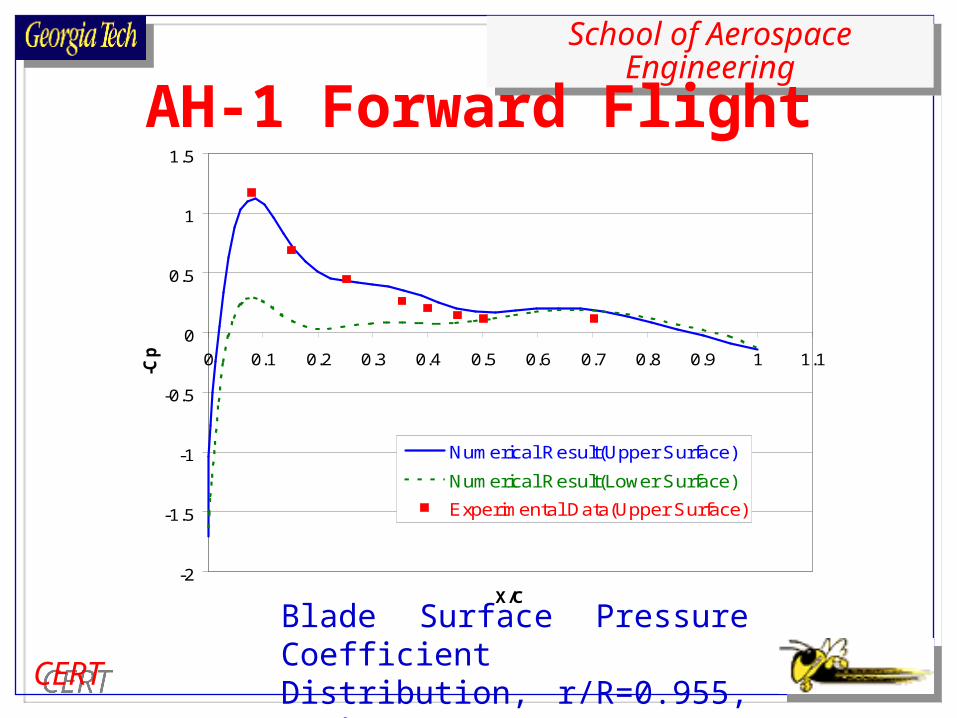
CERTCERT
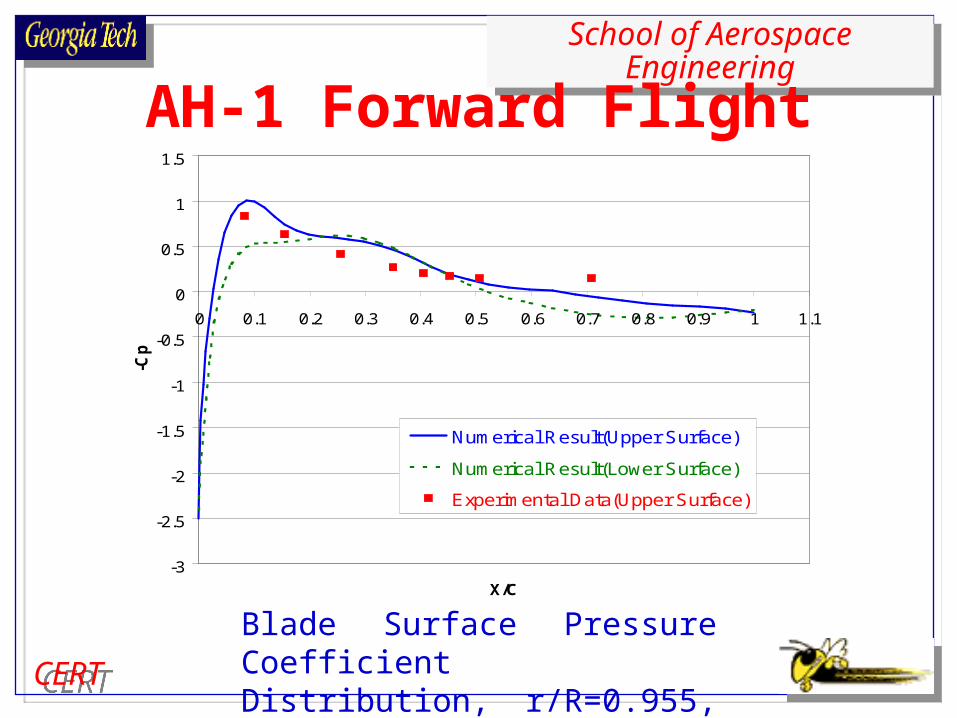
AH-1 Forward Flight
-2
-1.5
-1
-0.5
0
0.5
1
1.5
0 0.1 0.2 0.3 0.4 0.5 0.6 0.7 0.8 0.9 1 1.1
X/C
-Cp
Numerical Result(Upper Surface)
Numerical Result(Lower Surface)
Experimental Data(Upper Surface)
Blade Surface Pressure Coefficient Distribution, r/R=0.955, =0

School of Aerospace EngineeringSchool of Aerospace Engineering
CERTCERT
AH-1 Forward Flight
-2
-1.5
-1
-0.5
0
0.5
1
1.5
0 0.1 0.2 0.3 0.4 0.5 0.6 0.7 0.8 0.9 1 1.1
X/C
-Cp
Numerical Result(Upper Surface)
Numerical Result(Lower Surface)
Experimental Data(Upper Surface)
Blade Surface Pressure Coefficient Distribution, r/R=0.955, =90
School of Aerospace EngineeringSchool of Aerospace Engineering
CERTCERT
AH-1 Forward Flight
-3
-2.5
-2
-1.5
-1
-0.5
0
0.5
1
1.5
0 0.1 0.2 0.3 0.4 0.5 0.6 0.7 0.8 0.9 1 1.1
X/C
-Cp
Numerical Result(Upper Surface)
Numerical Result(Lower Surface)
Experimental Data(Upper Surface)
Blade Surface Pressure Coefficient Distribution, r/R=0.955, =180

School of Aerospace EngineeringSchool of Aerospace Engineering
CERTCERT
How well does the Low Dispersion Scheme model tip vortices?
Schematic of hover rotor wake structure

School of Aerospace EngineeringSchool of Aerospace Engineering
CERTCERT
Caradonna & Tung Rotor Test Parameters
Untwisted rectangular NACA0012 blades Hovering condition MTip=0.44
Collective Pitch c=8

School of Aerospace EngineeringSchool of Aerospace Engineering
CERTCERT
Caradonna & Tung RotorMTip=0.44
TURNS-LDFV TURNS-MUSCL
Vorticity Magnitude Contour
Vortex I
Vortex II
Vortex I

School of Aerospace EngineeringSchool of Aerospace Engineering
CERTCERT
Caradonna & Tung RotorMTip=0.44, r/R=0.80, Grid size 79 45 31
-2.5
-2
-1.5
-1
-0.5
0
0.5
1
1.5
-0.2 0 0.2 0.4 0.6 0.8 1 1.2
x/C
-Cp
TURNS-MUSCL
TURNS-LDFV
Experimental Data
Blade Surface Pressure Distribution

School of Aerospace EngineeringSchool of Aerospace Engineering
CERTCERT
CONCLUSIONS
A Low-Dispersion Finite Volume scheme has been developed and implemented into TURNS, a finite volume CFD code.
Encouraging agreement between the predicted results and experiment data has been obtained for shock noise on coarse grid.

School of Aerospace EngineeringSchool of Aerospace Engineering
CERTCERT
CONCLUSIONS
Basic characteristics of BVI noise are predicted with satisfactory accuracy.
TURNS-LDFV can capture main features of the tip vortex system with good resolution on coarse grids.

School of Aerospace EngineeringSchool of Aerospace Engineering
CERTCERT
PROPOSED WORK
Determine the minimum number of grid points needed to predict shock noise.
Identify the contributions of different noise sources.

School of Aerospace EngineeringSchool of Aerospace Engineering
CERTCERT
PROPOSED WORK
Repeat forward flight BVI calculation on fine grid; Incorporate trim effects.
Further investigation of BVI noise investigated in Higher harmonic control Aeroacoustic Rotor Test (HART) program.
Related Documents