DRAFT REPORT Schaake Property Habitat Improvement Project Basis of Design Report – 30 Percent Design Prepared for Bureau of Reclamation Yakima River Basin Water Enhancement Project November 2, 2015 CH2M HILL, Inc. 322 East Front Street Suite 200 Boise, ID 83702

Welcome message from author
This document is posted to help you gain knowledge. Please leave a comment to let me know what you think about it! Share it to your friends and learn new things together.
Transcript

D R A F T R E P O R T
Schaake Property Habitat Improvement Project
Basis of Design Report – 30 Percent Design
Prepared for
Bureau of Reclamation
Yakima River Basin Water Enhancement Project
November 2, 2015
CH2M HILL, Inc. 322 East Front Street Suite 200 Boise, ID 83702


Contents Section Page
Acronyms and Abbreviations .............................................................................................................. v
1.0 Introduction ....................................................................................................................... 1-1 1.1 Purpose ............................................................................................................................ 1-1 1.2 Report Organization and Supporting Documents............................................................ 1-1 1.3 Vision................................................................................................................................ 1-2 1.4 Goals ................................................................................................................................ 1-2 1.5 Project Setting .................................................................................................................. 1-3
1.5.1 Location .............................................................................................................. 1-3 1.5.2 Site Characteristics .............................................................................................. 1-3
1.6 Project History ................................................................................................................. 1-4 1.7 Stakeholder Involvement ................................................................................................. 1-5
2.0 Project Description ............................................................................................................. 2-1
3.0 Basis of Design .................................................................................................................... 3-1 3.1 30 Percent Design Intent ................................................................................................. 3-1 3.2 Existing Site Conditions .................................................................................................... 3-1
3.2.1 Topography ......................................................................................................... 3-1 3.2.2 Site Features ....................................................................................................... 3-1 3.2.3 Wetlands ............................................................................................................. 3-2 3.2.4 Existing Levees .................................................................................................... 3-2 3.2.5 Soil Nutrients ...................................................................................................... 3-3
3.3 Access, Staging, and Site Preparation .............................................................................. 3-3 3.3.1 Clearing, Grubbing, and Stripping ....................................................................... 3-3 3.3.2 Construction Access ............................................................................................ 3-4 3.3.3 Construction Staging and Storage ...................................................................... 3-4 3.3.4 Offsite Spoil Area ................................................................................................ 3-5 3.3.5 Permanent Access ............................................................................................... 3-5
3.4 Site Isolation and Dewatering .......................................................................................... 3-6 3.4.1 Side Channels and Alcoves .................................................................................. 3-6 3.4.2 Wetland E ............................................................................................................ 3-6
3.5 Existing Levee Removal .................................................................................................... 3-6 3.5.1 Levee Removal .................................................................................................... 3-6 3.5.2 Floodplain Regrading .......................................................................................... 3-7 3.5.3 Utility Considerations ......................................................................................... 3-8
3.6 Setback Levee .................................................................................................................. 3-8 3.6.1 Horizontal Alignment .......................................................................................... 3-9 3.6.2 Vertical Profile / Level of Protection ................................................................... 3-9 3.6.3 Cross Section ..................................................................................................... 3-10 3.6.4 Embankment Material ...................................................................................... 3-11 3.6.5 Borrow Area ...................................................................................................... 3-11 3.6.6 Slope Protection ............................................................................................... 3-12 3.6.7 Crossing Features .............................................................................................. 3-12 3.6.8 Potential for Seepage-Induced Inundation ....................................................... 3-13
3.7 Side Channels and Alcoves ............................................................................................. 3-13 3.7.1 Design Approach and Reference Reach ............................................................ 3-13
WT0810151016BOI III
Section Page
3.7.2 Geomorphic Design Recommendations ........................................................... 3-14 3.7.3 Side Channels .................................................................................................... 3-15 3.7.4 Alcoves .............................................................................................................. 3-18 3.7.5 Woody Material ................................................................................................ 3-19
3.8 Revegetation .................................................................................................................. 3-19 3.8.1 Revegetation of Disturbed Areas ...................................................................... 3-19 3.8.2 Revegetation for Habitat Improvement ........................................................... 3-20
3.9 Erosion and Sediment Control ....................................................................................... 3-20
4.0 Regulatory Requirements .................................................................................................... 4-1
5.0 Design Implementation ....................................................................................................... 5-1 5.1 Procurement Strategy ...................................................................................................... 5-1 5.2 Contract Documents ........................................................................................................ 5-1 5.3 Construction Constraints and Sequencing ....................................................................... 5-1 5.4 Construction Monitoring ................................................................................................. 5-2
6.0 Next Steps .......................................................................................................................... 6-1 6.1 Short-Term Milestones .................................................................................................... 6-1 6.2 Long-term Milestones ...................................................................................................... 6-2
7.1 References .......................................................................................................................... 7-1
Appendixes
A Schaake Property Habitat Improvement Project, Draft Geotechnical Recommendations Report B 30 Percent (Preliminary) Design Drawings C Bid Schedule D List of Specifications
Tables
4-1 Summary of Anticipated Permits and Approvals 6.1 Short-term Project Milestones 6-2 Long-term Project Milestones
Exhibit(s)
Exhibit 1 Summary of Phase 1 Proposed Goals, Objectives, Performances Standards, and Monitoring Methods
Exhibit 2 Schaake Property Habitat Improvement Project Concept Map Exhibit 3 Summary of Project Alternatives Exhibit 4 Schaake Planning Group Participants Exhibit 5 Summary of Key Stakeholder Meetings Exhibit 6 Summary of Data Sources Used to Develop Existing Conditions Digital Terrain Model Exhibit 7 Results of Soil Phosphorus Sampling Data (from Land Profile, Inc., 2007) Exhibit 8 Mean Daily Discharge for ELNW Hydromet Gage, 1976 to 2012
CONTENTS
WT0810151016BOI IV

Acronyms and Abbreviations ACB articulating concrete blocks
ACE annual chance exceedance
BDR Basis of Design Report
BFE base flood elevation
BPA Bonneville Power Administration
Cfs cubic feet per second
CH2M CH2M HILL, Inc.
City City of Ellensburg
CLOMR Conditional Letter of Map Revision
County Kittitas County
CY cubic yards
DPW Department of Public Works
DTM digital terrain model
EA Environmental Assessment
Ecology Washington Department of Ecology
EM Engineering Manual
ESA Endangered Species Act
ETL Engineering Technical Letter
FEMA Federal Emergency Management Agency
FESL fabric-encapsulated soil lifts
ft/s feet per second
GRR Geotechnical Recommendations Report
HDPE high-density polyethylene
HPA hydraulic project approval
HVF high-visibility fence or flagging
I-90 Interstate 90
JARPA Joint Aquatic Resources Permit Application
kV kilovolt
LWM large woody material
mg/kg milligrams per kilogram
NLD National Levee Database
NMFS National Marine Fisheries Service
NOI Notice of Intent
WT0810151016BOI V

ACRONYMS AND ABBREVIATIONS
NPDES National Pollutant Discharge Elimination System
Project Schaake Property Habitat Improvement Project
PUD Public Utility District
Reclamation Bureau of Reclamation
RM river mile
RMSE root mean square error
SEPA State Environmental Policy Act
STA station
SWPPP Stormwater Pollution Prevention Plan
TCF Twin City Foods, Inc.
TESC temporary erosion and sediment control
TSC Technical Service Center
USACE United States Army Corps of Engineers
USFWS United States Fish and Wildlife Service
WAC Washington Administrative Code
WSDOT Washington Department of Transportation
WDFW Washington Department of Fish and Wildlife
WSE Watershed Science and Engineering, Inc.
WWTP wastewater treatment plant
YRBWEP Yakima River Basin Water Enhancement Project
WT0810151016BOI VI

SECTION 1
Introduction 1.1 Purpose This Basis of Design Report (BDR) provides a project overview and documents the key design criteria, assumptions, analyses, and decisions related to the 30 Percent (Preliminary) Design and future construction of the Schaake Property Habitat Improvement Project (Project). This BDR is prepared for review by the Bureau of Reclamation (Reclamation), project partners, regulatory agencies, and landowners to solicit feedback on the 30 Percent Design. In addition to providing detailed documentation for the Project, this BDR also summarizes the Project’s vision and goals, existing conditions and rationale for the Project, history, stakeholder involvement, anticipated permits, and the expected schedule and “next steps” to implement the Project. This BDR complements the 30 Percent Design Package and provides reviewers a more thorough understanding of the project and the rationale for its development.
1.2 Report Organization and Supporting Documents The BDR was developed as one deliverable composing the 30 Percent (Preliminary) Design Package that also included the following deliverables:
• Drawings, provided as Appendix B
• Bid Schedule, provided as Appendix C
• List of Specifications, provided as Appendix D
• Basis of Cost Estimate Technical Memorandum and Cost Estimate, provided separately (due to sensitive information)
The BDR was organized into the following sections for reviewers to efficiently access desired information:
• Section 1: Introduction provides background information and over-arching design criteria relevant to the overall Project.
• Section 2: Project Description provides a general summary of the proposed project, focused around material quantities and project footprint.
• Section 3: Basis of Design provides detailed technical criteria used to design specific project features presented in the Drawings, provided as Appendix B.
• Section 4: Regulatory Considerations summarizes expected permits that will be required for project construction and summarizes the intended approach for project permitting.
• Section 5: Design Implementation summarizes the intended approach to construct the project.
• Section 6: Next Steps summarizes the short- and long-term milestones required to design, permit, construct, and monitor success of the Project.
In addition to the BDR, two reports and technical memorandums were developed with the BDR to document detailed technical analyses undertaken as part of the design of the Project. These reports are summarized within the BDR and include the following documents:
• Schaake Property Habitat Improvement Project, Draft Geotechnical Recommendations Report (CH2M HILL, 2015a), provided as Appendix A, summarizes the existing site geology, geotechnical
WT0810151016BOI 1-1

SECTION 1 – INTRODUCTION
field investigation program, data reduction, geotechnical analyses, geotechnical design, and construction considerations for the proposed setback levee.
• Schaake Property Habitat Improvement Project, Draft Hydraulic Modeling Report (Reclamation, In Press) documents the methodology and results of hydrologic analyses and hydraulic modeling performed for the project.
1.3 Vision Reclamation purchased the 285-acre Schaake property in August 2003, “because of the high potential … to improve steelhead and salmonid habitat and to place additional riparian land into public ownership with increased public benefit” (Reclamation, 2013). The Project is one part of the overall restoration plan for the Schaake Property that is envisioned to restore natural and sustainable processes that create and maintain complex and abundant aquatic and riparian habitat in this reach of the Yakima River (Graham, 2015).
Through reconnection of the Yakima River to its geomorphic floodplain, the Project will provide perennial access to now-disconnected, off-channel floodplain habitat for rearing salmonids. The off-channel habitat will increase the carrying capacity of the Yakima River and its floodplain, and reduce stranding potential and mortality of juvenile salmonids.
The Project will also provide benefits to the mainstem Yakima River in the vicinity of the Project and farther downstream. As high flows access the floodplain, shear stresses in the mainstem decrease. Assuming the hydrology, supply of sediment and wood, and grain size of sediment remain constant, sediment and large woody material (LWM), which currently are conveyed through the reach to deposit downstream, are expected to deposit within the Project reach, creating and maintaining in-channel habitat complexity. Downstream benefits also are anticipated. Water that accesses and is stored on the floodplain reduces downstream peak discharges during high flows and recharges shallow groundwater, thereby helping maintain flows and cooler water temperatures during low flows. Riparian vegetation also is expected to benefit from the Project as higher groundwater levels support cottonwoods, willows, and other native riparian vegetation similar to the vegetation in accessible floodplains immediately downstream of the Project.
1.4 Goals Completed in 2011, the Schaake Property Habitat Improvement Design, Phase 1 Report (Phase 1 Report) proposed five overall goals and 18 specific objectives established by Reclamation for the Project (CH2M HILL, 2011a). Since the Phase 1 Report was produced, further discussions and planning have resulted in one of the goals and five of the objectives no longer being applicable. Excluding these goals and objectives, the following goals and associated objectives specified by Reclamation for the Project and originally summarized in the Phase 1 Report were used to guide the development of the 30 Percent Design:
• Goal 1. Create and maintain refuge and rearing habitat for juvenile salmonids.
− Objective 1.1. Provide rearing habitat during spring and fall and provide refuge habitat during high flows for Chinook salmon, summer steelhead, and coho salmon.
– Objective 1.2. Increase geomorphic (hydraulic and habitat) complexity through the reach.
• Goal 2. Promote natural geomorphic processes as much as possible while reducing ongoing maintenance.
WT0810151016BOI 1-2

SECTION 1 – INTRODUCTION
Objective 2.1. Maintain irrigation flows in Tjossem Ditch by incorporating features into the design to maintain the existing flows and establish an operations and maintenance plan to implement if necessary.
Objective 2.2. Design and construct project to promote channel‐floodplain interaction while managing risk of channel avulsion into floodplain.
Objective 2.3. Allow side channels to evolve through natural processes.
Objective 2.4. Induce bed aggradation (sediment deposition) by diverting water into the floodplain.
Goal 3. Maintain or decrease the risk of flooding at downstream and adjacent properties.
Objective 3.1. Define the current level of protection and reach consensus with landowners.
Objective 3.2. Incorporate features into the design to maintain the existing level of protection.
Objective 3.3. Better define Wilson Creek (existing and proposed conditions) using two‐dimensional hydraulic modeling.
Goal 4. Protect existing infrastructure from inundation and erosion at the design discharge.
Objective 4.1. Complete the flow frequency analyses and determine the design discharges for the Yakima River and Wilson Creek.
Objective 4.2. Protect Interstate 90 (I‐90).
Objective 4.3. Protect the City’s wastewater treatment plant (WWTP), pipeline, and outfall.
Objective 4.4. Protect Tjossem Ditch.
Exhibit 1 summarizes these goals and objectives and proposes performance standards for each, along with potential monitoring actions to document responses. A detailed monitoring plan for the implemented Project is provided as part of the Phase 1 Report (CH2M HILL, 2011a).
1.5 Project Setting 1.5.1 Location The Project Site is located immediately north and east of the Yakima River, south of I‐90, and west of Canyon Road in unincorporated Kittitas County (County), near the City of Ellensburg (City) (Exhibit 2). The area is part of the Ellensburg Basin (Kittitas Valley) in the upper Yakima River Basin of central Washington, and the Project Site is within the Shrub‐Steppe Vegetation Zone of the Columbia Basin Province, a vegetative complex that occupies the foothills of the eastern Cascade Mountains (Franklin and Dyrness, 1988). The Project Site is approximately bound by I‐90, Wilson Creek, Canyon Road, the Hansen Pits, the Yakima River, and Canyon Road.
1.5.2 Site Characteristics The Project Site is generally flat and slopes gradually southward toward the Yakima River, although a portion slopes towards Wilson Creek which transverses the northeastern portion of the Project Site in what is speculated to be a former channel of the Yakima River (Hilldale and Klinger, 2003). Most of the study area is located within the geomorphic and 100‐year floodplain of the Yakima River (as defined by the Kittitas County Flood Insurance Rate Map, [Federal Emergency Management Agency, 1981]). The site elevation is approximately 1,480 feet. The annual precipitation is 9 to 10 inches, and the growing season is approximately late March through mid‐October. Reclamation’s Schaake property is the largest
WT0810151016BOI 1‐3

SECTION 1 – INTRODUCTION
portion of the Project Site, but the Project will also include properties owned by the City of Ellensburg, Kittitas County, and two private landowners (Edward Stroh and Anthony “Skip” Mynar).
The existing land use across the Project Site varies and includes:
• Partially-developed areas, including gravel access roads, TCF spray fields where vegetable-processing effluent is land-applied, a private irrigation water conveyance ditch (Tjossem Ditch), above-ground electrical transmission lines, and former gravel mines (locally known as the Hansen Pits). These features, and others, are identified on Sheet G-004 of the 30 Percent (Preliminary) Design Drawings, provided as Appendix A.
• Formerly-developed areas, now intended to remain undeveloped, including open grasslands to the north of the Schaake Property that previously supported feedlots, manure stockpiles, and the Schaake slaughterhouse and rendering operations. These areas approximately correspond to the extent of brown-colored vegetation across the Schaake Property that is observable in aerial imagery that is provided as part of Exhibit 2.
• Undeveloped areas, including the forested riparian area near the Hansen Pits. Most of the undeveloped area is located on the riverside of the Schaake Levee.
Except for the Hansen Pits and one of the TCF sprayfields, development is separated from the Yakima River by the Schaake Levee, which separates the Yakima River from its historic floodplain until flows exceed approximately 24,000 cubic feet per second (cfs), an approximately 4 percent annual chance exceedance (ACE) event (Hilldale, In Press). On the landside2 of the Schaake Levee, vegetation mostly consists of upland grassland and shrub-forest fringes around existing wetlands. Revegetation efforts by Reclamation on portions of the Schaake property over the past decade have resulted in establishment of some native vegetation, but in many areas on the landside of Schaake Levee, vegetation is characterized by weedy and/or invasive species. Vegetation is sparse in some locations due to potentially high nutrient levels resulting from past land uses (as recently as 2003, the Schaake property supported a slaughterhouse, water treatment lagoons, feed lots, and a rendering plant).
In addition to the upland vegetation communities, some wetlands exist on both sides of the Schaake Levee (ICF Jones and Stokes, 2010; CH2M HILL, 2015b). Wetlands on the riverside are generally larger, regularly inundated (approximately every 2 to 5 years), and characterized by a shrub-forest overstory with an understory of reed canary grass, a state-listed Class C noxious weed (WAC, 2015a). Wetlands on the riverside of the Schaake Levee are generally smaller, and, although now sustained by natural hydrology, several of these wetlands may have initially resulted from various anthropogenic activities, including operations at the former Schaake facility (settling ponds), gravel mining operations, and operation of I-90 (drainage ditches).
1.6 Project History The Schaake Property was identified in the 2002 report The Reaches Project: Ecological and Geomorphic Studies Supporting Normative Flows in the Yakima River Basin, Washington (Stanford et al., 2002) as a site with high potential for riparian and aquatic habitat improvement. In August 2003, Reclamation purchased the Schaake Property to design, permit, and construct a project to improve riparian and aquatic habitat along the Yakima River. The property was purchased under the authority of the Yakima River Basin Water Enhancement Project (YRBWEP) legislation (Title XII of Public Law (PL) 103-434), which authorizes Reclamation “to evaluate and implement various measures to improve water management in the Yakima River Basin to protect, mitigate, and enhance fish and wildlife and improve the reliability of
2 Throughout this BDR, standard levee definitions of “riverside” and “landside” are used to denote the west and east sides, respectively, of the existing Schaake Levee and proposed setback levee. It is important to note that while the term “landside” is used, Wilson Creek is located on the landside of the levees.
WT0810151016BOI 1-4
SECTION 1 – INTRODUCTION
the water supply for irrigation” (Reclamation, 2012b). Shortly after acquiring the property, Reclamation changed the land use by removing the former slaughterhouse, lagoon, and manure stockpiles from the Schaake property. Over the following years, Reclamation chose not to renew leases for TCF to land-apply their vegetable processing effluent on 80 acres of the Schaake property.
As land uses were changing on the Schaake Property, more active habitat improvement plans for the Schaake Property were developed and analyzed in several studies completed by Reclamation’s Technical Service Center (TSC) (Hilldale and Klinger, 2003; Hilldale, 2004; Hilldale, 2007). During outreach with local landowners and project stakeholders to solicit feedback on the proposed habitat improvement plans, the principal component of the Project was identified: setting back the existing Schaake Levee to restore channel-floodplain connectivity. Establishment of side channels through linear depressions to provide habitat for juvenile salmonids was also incorporated to the Project at this time.
Following this outreach and decision, in 2009, CH2M HILL, Inc. (CH2M) was contracted by Reclamation to complete Phase 1 of the Schaake Habitat Improvement Project. The Phase 1 Report, completed in June 2011 (CH2M HILL, 2011a), proposed new locations for the setback levee and side channels on the left bank of the Yakima River, identified and addressed data gaps necessary to finalize a design, and described the anticipated physical process responses and sustainability of the proposed actions. Feedback from the October 2009 meeting with regulatory agencies, landowners, and other project stakeholders was incorporated into the final report.
Subsequently, in 2012, CH2M was retained by Reclamation to deliver Phase 2 of the Project, which encompasses the support of on-going efforts by Reclamation to describe the Yakima River’s existing conditions and its interaction with Wilson Creek; evaluation and selection of a preferred alternative; support preparing and procuring permits necessary to construct the preferred alternative; and preparation of bid documents (final design drawings, construction specifications, and cost estimates).
As part of Phase 2 of the project, CH2M and Reclamation built upon the TSC’s hydraulic modeling efforts and previous project alternatives and proposed two new alternatives (Alternatives 1 and 2) to project stakeholders for review and endorsement. During a June 2014 stakeholder meeting, Alternative 2 was selected as the preferred project alternative. Since that time, two iterations of the preferred alternative (Alternatives 2A and 2B) were developed to address stakeholder feedback provided in April 2015. Following review of Alternative 2A and Alternative 2B with Kittitas County in regards to potential flood risk, a third alternative, Alternative 3, was developed to meet the project goals and was advanced to the current 30 Percent Design. Exhibit 3 provides a full summary of project alternatives considered since inception of the Project in 2003.
1.7 Stakeholder Involvement The first stakeholder outreach meeting for the Project was held shortly after Reclamation’s purchase of the Schaake Property, in January 2004. Since then, numerous meetings have been held with local government and utilities, regulatory agencies, Yakama Nation, and local landowners to solicit feedback and address potential concerns regarding the proposed Project. The largest and best-attended of these meetings occurred on October 28, 2009, when Reclamation hosted a planning meeting in Ellensburg, Washington, for the Project. Over 35 people attended the meeting, including representatives from Reclamation and CH2M, the County, the City, TCF, Yakama Nation, Kittitas Public Utility District (PUD), Washington State Department of Transportation (WSDOT), Washington Department of Fish and Wildlife (WDFW), United States Army Corps of Engineers (USACE) (representatives of both the levee safety program and regulatory program), Washington Department of Ecology (Ecology), adjacent landowners, and other stakeholders. Collectively, this group of stakeholders composes the “Schaake Planning Group.” The most current list of participants in the Schaake Planning Group and their respective agencies, is included as Exhibit 4.
WT0810151016BOI 1-5

SECTION 1 – INTRODUCTION
At each stakeholder meeting, key decisions were made or critical feedback provided. Exhibit 5 summarizes the meetings where key decisions or feedback were provided.
WT0810151016BOI 1-6
SECTION 2
Project Description The intent of the proposed Schaake Property Habitat Improvement Project is to restore natural processes on the left bank of an approximately 2-mile reach of the Yakima River from Umptanum Road (approximately River Mile [RM] 153) to the Hansen Pits (approximately RM 151). Specifically, by reconnecting the Yakima River and its floodplain, the project will address a limiting factor contributing to the decline of salmonids in the Yakima Basin identified by Snyder and Stanford (2001): the loss of spatial habitat via disconnection of channels from their floodplains. The Project would provide the following benefits:
• Reconnect of 118 acres of the natural geomorphic floodplain of the Yakima River.
• Create of approximately 1.5 acres of wetland (additional wetlands may be created as the result of natural processes over the long-term).
• Create approximately 1.8 miles of perennial side channels by excavating approximately 0.8 miles of existing depressions and increasing flow connectivity to approximately 1.0 miles of existing side channels that are seasonally connected. In addition, backwater areas and existing floodplain ponds would also be connected.
• Improve flow connectivity of approximately 0.3 miles of existing alcoves by establishing a perennial downstream connection.
• Reduce stranding potential relative to existing conditions by establishing perennial flow through now seasonally disconnected side channels.
• Improve flow connectivity of the Tjossem Access channel, allowing year-round irrigation diversions to occur at the Tjossem Ditch headgate instead of current conditions which prevent diversions after approximately September 1.
• Reduce or reverse observed incision at the upstream end of the project reach, interpreted by Hilldale and Klinger (2003) as a result of confinement of the river through this reach. In turn, this could lead to increased activation of the floodplain.
• Attenuate high-flow events via temporary floodplain storage.
• Reduce flood risk at I- 90, the City WWTP, the BNSF railroad, and Wilson Creek through and downstream of the Schaake Property.
• Decrease operation and maintenance costs for the Schaake Levee.
The proposed benefits of the Schaake Project would result from setback of the existing Schaake Levee and creation of perennially-connected side channel and alcoves on the Project Site. The principal project components are identified in Exhibit 2 and would include the following:
• Construction of an approximately 1.3-mile long setback levee, varying in height from approximately two to eight feet, except at Wetland E where the levee height will be greater due to the depth of Wetland E. In total, the setback levee would require approximately 39,000 cubic yards (CY) of material to be imported or regraded onsite.
• Removal of approximately 0.8 miles of the existing Schaake Levee to the grade of the natural floodplain, entailing the excavation of approximately 21,500 CY of embankment material and approximately 300 CY of riprap.
WT0810151016BOI 2-1

SECTION 2 – PROJECT DESCRIPTION
• Excavation of approximately 12,500 CY of native material to establish perennial side channels through existing linear depressions currently disconnected by the Schaake Levee.
• Excavation of approximately 2,900 CY of native material to enhance existing alcoves to provide a perennial surface water connection and interact with groundwater.
• Import or onsite re-grading of approximately 220 CY of material to install a constructed riffle within a seasonally-connected side channel that currently activates at an estimated main channel discharge of 4,000 cfs (approximately the peak summer irrigation flow).
• Removal of four existing culverts and installation of three new culverts or small bridges to convey stormwater runoff through the setback levee, irrigation water through the setback levee, or vehicles across the proposed Side Channel 2.
• Temporary or permanent disturbance of approximately 30 acres, including approximately 0.4 acres of unavoidable, direct impacts to delineated wetlands and 1.6 acres of temporary and indirect impacts to delineated wetlands.
Additional details regarding the size, extent, and impact of proposed project elements are provided as part of the Drawings; additional calculations of expected impacts relevant to project permitting will be provided at the time permit applications are developed. Additional detail pertaining to the design of the Project is provided in Section 3 – Basis of Design.
WT0810151016BOI 2-2

SECTION 3 – BASIS OF DESIGN
Basis of Design 3.1 30 Percent Design Intent The intent of the 30 Percent Design is to convey the proposed project’s grading extent, quantities, and key elements. The 30 Percent (Preliminary) Design Package also provided the basis for an initial cost estimate and preliminary assessment of temporary and permanent project impacts and benefits. Following approval from Reclamation to proceed, CH2M will prepare subsequent design packages including specific dimensioning, horizontal and vertical control, concrete reinforcement, and related details necessary for bidding and construction.
3.2 Existing Site Conditions 3.2.1 Topography The existing contours shown on the Drawings were generated from a digital terrain model (DTM) originally developed to support the hydraulic modeling of the Yakima River and Wilson Creek in the project vicinity. The following data sources were used to generate the existing conditions DTM:
• Lidar survey (Optimal Geomatics, 2009)
• Riverbottom Road Survey (Kittitas County DPW, 2012)
• Tjossem Access Channel Survey (Reclamation, 2004)
• Tjossem Ditch Survey (Reclamation, 2006)
• Wilson Creek Survey (CH2M HILL, 2011b)
• Yakima River Bathymetric Survey (Reclamation, 2012b)
The lidar survey covered the majority of the project site and was collected for the USACE St. Louis District to provide a “high-resolution digital elevation model…covering the Yakima Training Center” (Optimal Geomatics, 2009). Based on the 95th percentile of the vertical fundamental root mean square error (RMSE) of 0.52 feet for the lidar survey, the lidar survey meets USACE survey accuracy requirements for “floodplain mapping” (USACE, 2015) and exceeds Federal Emergency Management Agency (FEMA) accuracy standards for the “highest” specification level (FEMA, 2010). Each of the six survey sources was transformed to the following common datum:
• Horizontal Datum: Washington State Plane Coordinate System, Washington South Zone, North American Datum of 1983, US Survey Foot
• Vertical Datum: North American Vertical Datum of 1988, U.S. Survey Foot
After transformation to a common datum, Autodesk® AutoCAD Civil3D 2011® software was used to merge the six data sources into a single DTM. Adjustments were made to the resultant DTM by incorporating two “correction” data sources developed by CH2M and Reclamation to reflect observed conditions and to smooth transitions between the different data sources. Exhibit 6 summarizes the original datum, description of the survey data source, and post-processing (including changes) that was performed on each survey source to generate the existing conditions DTM.
3.2.2 Site Features To develop a basemap for the Drawings, site features shown on the Drawings were located using remote-sensing methods, such as geo-locating utility maps or digitizing geo-rectified aerial imagery.
WT0810151016BOI 3-1

SECTION 3 – BASIS OF DESIGN
These remote-sensing methods are considered appropriate for identifying general locations of site features for the 30 Percent (Preliminary) Design Package, but the exact location of many site features (such as overhead electric lines and poles and extent of existing riprap) is required for final design or to reduce uncertainties related to site conditions that may result in change orders or increased construction costs. Therefore, Reclamation is planning an onsite survey prior to development of the 60 Percent Design Package.
3.2.3 Wetlands Delineation of wetlands on the Schaake Property and adjacent properties are documented in the Schaake Property Habitat Enhancement Project, Wetland Delineation Report (ICF Jones and Stokes, Inc., 2010) and Schaake Property Habitat Improvement Project, Wetland Delineation Report, Adjacent Properties (CH2M HILL, 2015b). The wetlands shown on the Drawings include all delineated wetlands, although a Request for Jurisdictional Determination has been submitted to regulatory agencies to determine whether wetlands along Tjossem Ditch (intermittent ditch not excavated in or relocating a tributary to a Water of the U.S.) and within the Hansen Pits (water-filled depression created in dry land incidental to mining) are jurisdictional.
3.2.4 Existing Levees Several levees exist within close proximity to the project site and have an effect on existing and post-project hydraulic and geomorphic conditions, as well as flood risk. With the exception of the Schaake Levee, the design of the Project assumed all existing levees would remain in their existing condition. Per the USACE National Levee Database (NLD), the following regulated levees exist within the project area:
• Schaake Levee, located on the Project Site is sponsored by Kittitas County. As of the most recent inspection, the Schaake Levee is rated as minimally acceptable (USACE, 2014a). The Schaake Levee will be setback as part of the Project.
• Jensen Levee, located on the right bank of the Yakima River across from the former location of the Schaake processing plant. The Jensen Levee was sponsored by Kittitas County and as of the most recent inspection, the Jensen Levee is rated as unacceptable (USACE, 2015). At the time of this report, the landowner is currently pursuing funding for the design of a project to improve or setback the Jensen Levee.
• Jeffries Levee, located on the right bank of the Yakima River across from the City’s WWTP outfall is sponsored by Kittitas County. As of the most recent inspection, the Jeffries Levee is rated as minimally acceptable (USACE, 2015). The Jeffries Levee also includes the portion of Riverbottom Road that was upgraded in 2011 to also function as a flood control levee (Kittitas County Department of Public Works [DPW], 2011). At the time of this report, Kittitas County is considering several potential modifications or setback of the Jeffries Levee (Watershed Science and Engineering, Inc. [WSE], 2015), but no decisions have been made.
In addition to levees recorded in the NLD, two other levees exist within the vicinity of the Project Site:
• Unnamed Levee, located on the right bank of the Yakima River upstream of the location where the Jeffries Levee is built directly upon the Yakima River. This levee appears to be a historic levee that was breached, but a significant portion of the levee prism can still be observed in the existing conditions DTM.
• Hansen Pits Levee, located on the left bank of Yakima River along the Hansen Pits. The levee is currently breached and a surface water connection to a former gravel mining pit exists. At the time of this report, Kittitas County is not intending to repair the breach but is considering options that may include the modification, setback, or removal of the levee (WSE, 2015). However, no decisions have been made regarding the future of the Hansen Pits Levee.
WT0810151016BOI 3-2

SECTION 3 – BASIS OF DESIGN
3.2.5 Soil Nutrients As a result of past land uses (cattle feedlots, slaughterhouse operation, and land application of vegetable processing effluent), soils are highly enriched with phosphorus at multiple locations on the Schaake Property. To characterize phosphorus levels on the Schaake Property, in 2007, Reclamation contracted Land Profile, Inc., to measure phosphorous levels near proposed side channels where sediments are most likely to be mobilized. Results of the 2007 study are mapped as part of Exhibit 7. Measured phosphorus concentrations ranging from 8 to 1,210 milligrams [of Phosphorus] per kilogram [of soil] (mg/kg) (Land Profile Inc., 2007). For comparison, 40 mg/kg is considered an excessive phosphorous concentration for areas east of the Cascades (Marx et al., 1999), although the Marx et al. study used a different testing methodology than Land Profile.
Given the Project’s intent to restore floodplain connectivity on the Schaake Property, nutrient-rich soils may be mobilized from the Schaake Property to the Yakima River, increasing phosphorus levels within the Yakima River. During the August 29, 2007 stakeholder meeting, Ecology expressed the opinion that the amount of soil and phosphorus entering the river would be negligible and that the best course of action may be to remove the phosphorus slowly through native vegetation (Rayforth, 2007), as would occur via revegetation of the site, described in detail in Section 3.8 – Revegetation. In addition, release of phosphorus is allowable to return the natural physical structure (for example, floodplain connectivity) of the Yakima River per WAC 173-201A-300 (Antidegradation) (WAC, 2015b):
Both temporary harm and permanent loss of existing uses may be allowed by the department where determined necessary to secure greater ecological benefits through major habitat restoration projects designed to return the natural physical structure and associated uses to a water body where the structure has been altered through human action.
Therefore, although the WAC allows mobilization of phosphorous, reasonable actions will be taken to reduce the potential for phosphorous mobilization to the extent possible as reflected in the 30 Percent Design Package. For example, as discussed in Section 3.7 – Side Channels and Alcoves, the side channel alignments were designed to generally avoid areas of the highest phosphorus concentrations, reducing the potential for phosphorous to be released via side channel evolution. Disturbed areas will be re-vegetated to reduce erosion potential (see Section 3.8 – Revegetation and Section 3.9 – Erosion and Sediment Control), further reducing the potential to mobilize phosphorous. Also, as riparian vegetation establishes across the Project Site, available soil phosphorous would be expected to be used and immobilized by that vegetation.
3.3 Access, Staging, and Site Preparation To protect existing vegetation, ongoing revegetation efforts by Reclamation, and sensitive resources, contractor access will be limited to areas of proposed work activities, access roads, staging areas, and storage areas. The Access and Staging Plan provided on Sheet C-001 of the Drawings presents an initial access and staging plan, but the contractor would be responsible for developing the final access and staging plan for Reclamation’s approval. Until that time, the Access and Staging Plan will provide the basis of impact calculations for permitting, and the contractor’s final access and staging plan will need to work within the permitted allowances.
3.3.1 Clearing, Grubbing, and Stripping Woody vegetation not marked for protection will be cleared within the project limits, with the objective to re-use as much of it as possible for habitat within constructed side channels and alcoves, as described in Section 3.7.3 – Woody Material. Otherwise, the surface preparation (clearing, grubbing, and/or stripping) will vary by the proposed project element as summarized below:
WT0810151016BOI 3-3

SECTION 3 – BASIS OF DESIGN
• Access roads, staging areas, and storage areas may not require clearing in areas where existing vegetation is sparse, short grasses that can be easily traversed by construction equipment without reducing traction. Where existing vegetation is taller or denser, vegetation would be cut or mowed to ground level, with the intent to allow it to re-establish after construction.
• Excavation areas would be cleared and grubbed, with relatively clean grubbed material stockpiled for reuse onsite as topsoil.
• The footprint of the setback levee would be cleared, grubbed, and stripped to remove all organic materials and unsuitable soils. This will allow a firm foundation to construct the proposed setback levee. Relatively clean stripped material may be stockpiled and reused onsite as topsoil.
3.3.2 Construction Access Construction access will include both existing and constructed temporary access roads. Entrances to the Project Site will be located at the north and east boundaries of the Project Area, from Umptanum Road and Canyon Road (via the parking lot for the City’s wastewater treatment plant), respectively. Existing access roads will be used to the extent possible and it is assumed that existing soils are capable of supporting the construction machinery; however, many proposed work areas are not currently accessible and will require temporary construction access. Also, as construction progresses, some existing roads will be removed where and when they conflict with construction and alternate routes will be created as necessary to complete construction. Temporary construction access roads were generally developed to reduce crossings beneath overhead utilities or over underground utilities. Also, to reduce crossing and associated impacts to wetlands and irrigation features, turnarounds will be placed near Tjossem Ditch and Wetland E. Temporary construction access roads are anticipated to include the following:
• A double-wide access road located along the riverside of the setback levee for two-way traffic and heavy machinery.
• Several single-wide access road spurs from existing roads to access alcoves and side channels. To extent possible, these temporary access roads will be located in less dense vegetation.
• Several single-access roads to provide haul loops for efficient construction.
Temporary construction access roads will include grading improvements, subgrade compaction, and drainage improvements where necessary. Temporary construction access roads may require placement of a new road section consisting of 6 to 8 inches of crushed angular rock at least 12 feet wide in areas that need to be improved. Temporary access road width is based upon vehicle size and turning radius. At the end of construction, imported materials for temporary access roads will removed from the Project Site and the underlying soils will be ripped, disked, or tilled to loosen the soil, and re-seeded (see Section 3.8 – Revegetation).
3.3.3 Construction Staging and Storage Anticipated materials to be staged include riprap, streambed gravel, plant material, imported fill, and excess spoils from the excavated channels and levee removal. Possible specialized equipment would include (but not be limited to) excavators, bulldozers, graders, loaders, haul trucks, and storage containers. Suitable spoils from the levee removal are expected to be stockpiled onsite and used as embankment material for levee construction, general fill, or topsoil. Unsuitable or surplus materials will be stockpiled and hauled to an approved offsite location.
Two staging and storage areas are located onsite: one centrally located in the northern half of the site in an upland area, and the second located within the designated borrow material location. Contractor staging and storage location considerations included:
WT0810151016BOI 3-4

SECTION 3 – BASIS OF DESIGN
• Proximity to work activity
• Travel time
• Overhead and underground utilities
• Wetland or riparian areas
• Construction sequencing (for example, using designated borrow material location prior to excavation).
Contractor staging and storage size considerations included:
• Vehicle size
• Quantity of vehicles
• Safe vehicle operational area
• Quantity of excavated material
Construction staging and storage areas will consist of grading improvements, subgrade compaction, and drainage improvements where necessary. Where necessary, staging and storage areas would be improved by placing 6 to 8 inches of crushed angular rock, although none is anticipated. At the end of construction, imported materials for improvement of staging and storage areas will be removed from the Project Site and the underlying soils will be ripped, disked, or tilled to loosen the soil, and reseeded (see Section 3.8 – Revegetation).
3.3.4 Offsite Spoil Area Anticipating some excavated material will be unsuitable for use as embankment material due to gradation, organic content, or other reasons, an offsite spoils area will be located south of the project site, between the Hansen Pits and the BNSF railroad. Unsuitable material and excess spoils will be stockpiled at this location. This location has been approved by Kittitas County who owns the land and will use the spoils for future projects throughout the County (D’Hondt, 2015).
3.3.5 Permanent Access A permanent access road will be constructed on the setback levee per guidance in the USACE’s Engineering Manual (EM) 1110-2-1913: Design and Construction of Levees (USACE, 2000). In conformance with EM 1110-2-1913 that requires access ramps or turnouts every 2,500 feet, the following access ramps or turnouts have been provided at an approximate spacing of 1,500 feet:
1. An access ramp near station (STA) 114+50
2. An access ramp near STA 123+00 to provide access to the existing monitoring well
3. A turnout near STA 140+50
4. An access ramp near STA 160+00 for access to the permanent Tjossem Ditch access road
Tjossem Ditch is an active irrigation supply ditch onsite. With the proposed elimination of the existing maintenance access route along the Schaake Levee, a permanent access route will be required for maintenance and operation of Tjossem Ditch and the Tjossem headgate. The new route will be accessed from the City WWTP via the setback levee and then follow the eastern bank of the ditch to the Tjossem headgate, near the portion of the existing Schaake Levee and access road that will be left in place.
WT0810151016BOI 3-5

SECTION 3 – BASIS OF DESIGN
3.4 Site Isolation and Dewatering 3.4.1 Side Channels and Alcoves As the proposed alcoves and side channels are designed to have perennial connections, the alcoves and side channels must be isolated from the Yakima River prior to construction to reduce the potential for fish in active constructions area. Supersacks filled with clean, river-run cobbles or similar coffering methods will be used to isolate the side channels and alcoves from the Yakima River. Prior to earthwork activities, the isolated areas will be electro-fished to remove fish from the isolated areas. Although side channel and alcove construction is planned during the fall when surface and groundwater levels in the Yakima River are lowest, groundwater will likely be encountered; however, anticipated groundwater levels are expected to be shallow such that excavation of the side channels may reasonably progress without dewatering. The contractor may choose to dewater the excavation area. Prior to commencing earthwork, the contractor will be required to submit a dewatering plan for approval.
3.4.2 Wetland E The setback levee will cross Wetland E from approximately STA 117+80 to STA 119+60. During construction, Wetland E will be dewatered to allow for the removal of soft sediments that have accumulated at the bottom of the pond. The soft sediments will then be excavated within the levee footprint to a firm bottom at the native alluvial sands and gravels. The levee will then be constructed up from this level.
3.5 Existing Levee Removal 3.5.1 Levee Removal The existing Schaake Levee, located on the left bank of the Yakima River, prevents high flows on the Yakima River from activating the existing floodplain until approximately a 4 percent ACE (25-year) peak discharge (Hilldale, In Press). To re-connect the floodplain and decrease the potential for stranding fish at high flows, the majority of the existing levee will be removed to match existing floodplain elevations, but a portion of the existing levee will remain in-place near the Tjossem headgate. Except at the northern end of the existing Schaake Levee, existing riprap along the levee will be removed, salvaged, and reused to protect the proposed setback levee.
At the upstream end of the Project Site, where the Yakima River is constricted between the Jensen Levee on the west bank and the Schaake Levee on the east bank, the Schaake Levee has artificially maintained a hard 90-degree bend in the Yakima River (“90-degree bend”) since 1975, the last known time that the Schaake Levee was repaired. In the 40 years since, the Schaake Levee has been subject to two 5 percent ACE (20-year) events in 2009 and 2011 and one 2 percent ACE (50-year) event in 1996. If the entirety of the Schaake Levee, including riprap, is removed, eastward migration of the river would be expected (Hilldale and Klinger, 2003; Hilldale, 2007). The exact timing, rate, and extent of lateral erosion cannot be predicted with absolute certainty but additional analysis would benefit the understanding of the potential implications of various designs on the 90-degree bend. Despite the uncertainty at the 90-degree bend, it can be assumed the higher the peak discharge, the longer the duration, and the sooner a high flow occurs after construction, the higher the likelihood that the left bank will migrate farther towards the setback levee, potentially in one high flow event.
To reduce the likelihood of rapid bank migration following construction, existing riprap below the finished floodplain elevation will be retained in place as proposed by Hilldale (2007). However, the existing riprap should not be expected to hold the Yakima River in its current alignment indefinitely; impinging flows on a bank that is overtopped at moderate discharges or simply a higher peak discharge
WT0810151016BOI 3-6

SECTION 3 – BASIS OF DESIGN
than occurred in 1996 are but two of the potential reasons that existing riprap could be eroded at the 90-degree bend. Hydraulic modeling results also indicate that flow patterns as a result of the Jensen Levee would contribute to velocities in excess of 10 feet per second (ft/s) across the newly connected floodplain. High velocities on the newly connected floodplain may erode soils behind the riprap that could result in failure of the riprap protection. High velocities on the floodplain could also indicate a potential alignment that could be eroded during a high flood and be occupied by all or part of the Yakima River.
While removal of the Schaake Levee is necessary for the project to achieve the goal of improving floodplain connectivity, additional analysis is required prior to developing a final design at the 90-degree bend. For the 30 Percent Design, riprap was designed along the setback levee in the vicinity of the 90-degree bend, as described in Section 3.6.5 – Slope Protection. However, the prescribed riprap size, extents, and depth may increase to address potential uncertainty regarding the future alignment of the Yakima River. Potential solutions to address the high velocities on the newly-connected floodplain are summarized as part of Section 3.5.2 – Floodplain Regrading.
3.5.2 Floodplain Regrading On the landside of the Schaake Levee at the 90-degree bend, the topography generally slopes eastward, from the existing Schaake Levee to I-90. Without regrading, high flows accessing the floodplain at this location would access the floodplain, then flow towards the setback levee at velocities approaching 10 to 12 ft/s (Hilldale, In Press), creating a potential erosional condition along the riverside toe of the proposed setback levee.
To reduce the potential for an erosional condition, approximately 8.9 acres between the existing Schaake Levee and the proposed setback levee near the 90-degree bend will be re-graded to provide drainage away from the toe of the setback levee and toward the Yakima River. Setting the lowest portion of the re-graded floodplain at an elevation corresponding to the 50 percent ACE (2 year) water surface elevation, the re-graded floodplain will allow the Yakima River to more frequently access its floodplain, reduce risk to the setback levee, and reduce the potential for fish stranding. To allow the floodplain re-grading, an existing well will be decommissioned and the associated pump house will be removed; according to Reclamation the water right for the pump has been surrendered to increase baseflows in the Yakima River, and the well has no value to Reclamation (Graham, 2015).
Hydraulic modeling of the 30 Percent Design performed by Reclamation identified the potential for high velocities across the re-graded floodplain that could create an avulsion or split-flow condition (Hilldale, In Press). This high velocity is partially a result of flow patterns induced by the Jensen Levee that direct flows onto the left floodplain, but is also partially a result of increased conveyance across the floodplain from the proposed re-grading; however, it is important to note that without this re-grading, high velocities would be concentrated against the setback levee (Hilldale, 2007). To manage the high velocities and address potential river migration, future design iterations will consider one or more of the following options, which may be implemented individually or together:
1. Expect that the left bank will migrate to the setback levee and design setback levee riprap protection to remain stable for existing hydraulic conditions at the Schaake Levee;
2. Increase the elevation of the re-graded floodplain to match that of the west bank, thereby reducing the conveyance capacity of the floodplain;
3. Re-shape and re-armor the left bank of the 90-degree bend;
4. Increase roughness of the re-graded floodplain by adding strategically-placed floodplain wood, with the intent to reduce conveyance capacity of the floodplain and/or re-direct flows;
5. Increase roughness of the floodplain using vegetation that may include planting vegetation in “windrows” or as flood fences;
WT0810151016BOI 3-7

SECTION 3 – BASIS OF DESIGN
6. Deflect flow away from the left bank and floodplain by installing LWM structures; and
7. Retain a portion of the Schaake Levee in place until vegetation stabilizes the floodplain and/or the Jensen Levee is re-configured or removed.
3.5.3 Utility Considerations Three known utilities have been identified and will be exposed to the Yakima River with setback of the existing Schaake Levee:
• An abandoned gas line between Umptanum Road and the former Schaake slaughterhouse is proposed for removal. As much of the abandoned line would be removed as possible, presumably from the terminus of the line to the valve closest to the main gas line. Removal of the gas line will reduce the potential that the abandoned pipe could be exposed if the river were to migrate, expose the abandoned portion of pipe, and potentially subject an active portion of the gas line to damage via fracturing or debris accumulation on the abandoned pipe.
• A 15-kilovolt (kV) overhead electric line known as the “E2 Feeder” that serves approximately 850 customers and is owned by Kittitas PUD. In a phone conversation with the PUD, the PUD stated that the PUD would require the E2 Feeder to be moved (Vosburgh, 2015). No decisions on how this relocation would be funded or when it would occur (before, during, or after construction) have been made.
• The 115-kV Columbia Transmission Line owned by the Bonneville Power Administration (BPA) is supported by a three-pole structure and is likely part of the power-sharing system that serves utilities across the Pacific Northwest. The Columbia Transmission Line may service in excess of 10,000 customers (Vosburgh, 2015). Prior to any decisions on whether the Columbia Transmission line would be maintained as is, upgraded, or relocated, BPA would likely require an Impact Study be self-performed by BPA. BPA would request this study fee be paid by the project proponent (Reclamation).
3.6 Setback Levee The proposed setback levee is a central Project component, allowing reconnection of the geomorphic floodplain and maintaining or improving flood risk management at critical infrastructure (I-90, the BNSF railroad, and the City’s WWTP). At this time, Reclamation is expected to fund design and construction of the Project and then transfer ownership of the setback levee to the County following construction. Reclamation and CH2M have solicited input from the County throughout project design (see Exhibit 5 for a summary of key stakeholder meetings), and Kittitas County provided the following direction and feedback during a meeting on May 27, 2015 (CH2M HILL, 2015c):
1. The setback levee should meet the eligibility requirements for Federal rehabilitation assistance through the USACE under PL84-99.
2. The setback levee should be designed to reduce long-term operation and maintenance costs to the extent possible.
3. The setback levee should consider the “best-and-highest” use for the site – specifically, limit flood impacts to undeveloped public lands to the extent possible.
It should be noted that in the following sections and throughout the BDR, the term “level-of-protection” refers only to surface flows, for example, at a given event, the Yakima River would not flow to the landside of the setback levee; however, underseepage or other subsurface flows may result in nuisance levels of inundation on the landside of the setback levee at peak discharges lower than those stated in the BDR. See Section 3.6.8 – Potential for Seepage-Induced Inundation for further discussion.
WT0810151016BOI 3-8
SECTION 3 – BASIS OF DESIGN
3.6.1 Horizontal Alignment The horizontal alignment of the proposed setback levee was designed to reconnect the greatest area of the now disconnected floodplain to the Yakima River; however, the following design considerations also impacted the proposed horizontal alignment:
• At its northern end, the setback levee ties into the I-90 embankment to limit the potential for high flows overtopping Umptanum Road to flank the setback levee.
• Between approximately STA 104+00 and STA 110+00, the setback levee limits impacts to the delineated wetland along the toe of I-90.
• Between STA 110+00 and STA 133+00, the setback levee does not encroach on the I-90 right-of-way, assumed to be 100 feet from the centerline of the eastbound highway centerline, the greatest offset distance of prohibited access identified on the right-of-way drawings for the I-90 project (Washington State Highway Commission, 1964).
o Between STA 117+80 to 119+60, the setback levee impacts Wetland E because a realignment around the wetland would create a significant constriction in the floodplain width that could increase the scour potential at the toe of the setback levee at the point of maximum constriction.
• Between STA 133+00 and STA 156+00, the horizontal alignment was set to reduce its encroachment on the Wilson Creek floodplain and avoid areas of the Wilson Creek floodplain that have a high conveyance.
• Between STA 156+00 and STA 168+00, the setback levee remains on Reclamation property to avoid impacts to TCF’s sprayfields.
• At its southern end, the setback levee ties into the existing Schaake Levee near the property ownership boundary between Reclamation and the City. The alignment follows a gradual curve here to provide a smooth hydraulic transition as high flows enter the downstream reach constricted by the Jeffries levee, existing Schaake Levee, and Tjossem spoils berm.
3.6.2 Vertical Profile / Level of Protection USACE’s “Interim Policy for Determining Eligibility Status of Flood Risk Management Projects for the Rehabilitation Program Pursuant to PL84-99” (USACE, 2014b) and discussions with Cathie Desjardin of the USACE’s Levee Safety Program were used to develop the following criteria pertinent to the level of protection to be provided by the proposed setback levee:
• Due to the presence of infrastructure located on the protected side of the Schaake Levee (I-90, BNSF railway, City’s WWTP, overhead electric, spray field operations), the setback levee would be classified as an urban levee under the USACE’s PL84-99 program (CH2M HILL, 2015d).
• For urban levees, the minimum level of protection for an urban levee under the PL84-99 program is the 10 percent ACE (10 year) plus 2 feet of freeboard (USACE, 2014b). The freeboard requirement increases to 3 feet in the vicinity of bridges (USACE, 2014b).
• The Project Sponsor can request a higher level of protection. Both the County, as the agency that would apply for the PL84-99 program, and the City, as owner of critical public infrastructure protected by the levee, would be project sponsors (CH2M HILL, 2015d).
– At the direction of Kittitas County, the setback levee should provide a level of protection at least equal to what is currently provided by the existing Schaake Levee (CH2M HILL, 2015d).
– At the direction of Kittitas County, the alignment and profile of the setback levee should consider the “best and highest land use” of affected properties. Specifically, increases in flood
WT0810151016BOI 3-9
SECTION 3 – BASIS OF DESIGN
depths should be avoided at inhabited structures and contained first on public lands and conservation properties, then on uninhabited portions of private property (CH2M HILL, 2015e).
• The level of protection provided by a levee is the discharge that first overtops any portion of the levee; the setback levee cannot be subdivided to have different levels of protection (CH2M HILL, 2015d).
To accommodate the County’s request to reduce maintenance costs, an overflow control structure was incorporated into the setback levee. The controlled overflow control structure is designed to activate at a discharge of 24,000 cfs, the existing level of protection provided by the Schaake Levee, which is greater than the PL84-99 10 percent ACE plus 2 feet freeboard requirement. The remainder of the setback levee profile is designed to provide a level of protection equal to the 1 percent ACE plus 1 foot of freeboard (CH2M HILL, 2015d), which is greater than the existing level of protection and the 10 percent ACE plus 2 feet free requirements. The goal of incorporating an overflow control structure is to control overtopping discharges to a small portion of the levee that could be protected to withstand overtopping flows while the remainder of the levee would be set to a higher elevation that would not overtop until a much higher discharge. The decision to incorporate an overflow control structure considered the following benefits:
• Raising the level of protection across the rest of the setback levee would reduce long-term operation and maintenance costs by reducing the frequency of overtopping.
• Raising the level of protection across the rest of the setback levee significantly reduces the needs for erosion protection along the landside of the levee, which would also reduce construction costs.
• Erosion protection can be provided at the overflow control structure to resist expected hydraulic forces and reduce the potential that repairs (including operation and maintenance costs) will be needed after overtopping events.
• Initial overtopping flows can be directed towards less critical, unpopulated portions of land where the impact of flooding is lower. With the selected location of the controlled overflow structure, the 1 percent ACE would not overtop portions of the setback levee upstream and lateral to the City’s WWTP and Wilson Creek, thus reducing flood risk at these locations.
Further complicating the design of the level of protection are impacts to FEMA regulatory base flood elevations (BFE), or the expected water surface elevation at the 1 percent ACE (100-year) peak discharge. With a level of protection less than the 1 percent ACE, both the existing Schaake Levee and the proposed setback levee function similar to a lateral weir, controlling the quantity of flow from the Yakima River that is able to access the east floodplain, on the landside of the setback levee. As a result, the vertical profile of the setback levee affects the partitioning of the base flood between the Yakima River and the left floodplain; thus, it is possible that too wide or too low of a controlled overflow control structure could result in a greater quantity of flow accessing the east floodplain than currently occurs thereby increasing modeled BFEs at that location and vice versa.
With guidance from Kittitas County and Ecology that FEMA Region X has a provision to allow BFE increases within the floodway for fish habitat projects, provided the increases are reduced to the extent feasible (FEMA, Undated), an additional benefit of the controlled overflow structure is greater control in the discharge that passes between the two sides of the floodplain to limit potential increases in BFEs to portions of the floodplain free of residential structures or critical infrastructure.
3.6.3 Cross Section The cross section of the setback levee will have a nominal 12-foot-wide crest, which meets the minimum width of 10 feet recommended for normal maintenance operations and flood-fighting operations per EM 1110-2-1913 (USACE, 2000). The riverside and landside slopes will be 3H:1V (horizontal to vertical).
WT0810151016BOI 3-10

SECTION 3 – BASIS OF DESIGN
The riverside face of the levee will be armored with riprap or a well-graded silty, gravel with coarse material that will be revegetated as described in Section 3.6.5 – Slope Protection. Six inches of crushed gravel surfacing material will be placed on the crest to support vehicular traffic (see Section 3.3.5 – Permanent Access for additional discussion).
As discussed in the previous section, a controlled overflow structure will be incorporated into the levee to meet level-of-protection design criteria, and the structure will be set lower than the remaining levee to focus initial overtopping at this structure. This would allow the landside property, owned by the City and utilized by TCF for land-application of their vegetable-processing effluent, to flood, similar to the current conditions. The low crest levee (controlled overflow structure) will extend from STA 162+22 to STA 166+85, and it will also have a 12-foot-wide crest. The riverside slope will be 3H:1V, and the landside slope will be 5H:1V to provide additional stability during an overtopping flow scenario. As discussed in Section 3.6.5 – Slope Protection, the entire section will be covered with an articulated concrete blocks overlying a nonwoven geotextile to both protect the levee during overtopping and allow vehicular traffic to cross the controlled overflow structure.
3.6.4 Embankment Material To the extent possible, the proposed setback levee will be constructed using material obtained from two primary onsite sources: (1) native soils obtained from designated borrow areas and (2) reuse of the existing Schaake Levee soils that will be demolished as part of the Project. The native soils encountered during geotechnical explorations are discussed in the Geotechnical Recommendations Report (GRR) (Appendix A).
The material from onsite borrow sources will vary and consist of some areas of silt and clay and other areas of sandy gravel with varying amounts of silt, silty sand, and silt with sand. CH2M recommends selective borrowing for construction of the setback levee to avoid material lenses that may consist of clean (low fines) sands or gravels. The identified onsite borrow area is anticipated to have some predominantly fine-grained alluvial deposits (silts and clays) that are recommended for mixing with coarse-grained alluvial soils to achieve a well-graded blend. Ultimately, embankment fill material used to construct the levee will be required to contain a minimum of 25 percent fines, but it is expected that the onsite source fines’ content will vary between 25 percent and 50 percent fines.
Generally speaking, the existing levee material should be suitable for constructing the setback levee. Approximately 75 percent of the existing levee material is planned for reuse in the proposed setback levee, assuming that the top portion of the Schaake Levee will be grubbed of vegetation and organic matter. As indicated by the gradation results provided in Appendix B of the GRR, the existing levee material typically contains less than 20 percent fines. Natural moisture content of the levee material was found to be near or below the optimum moisture content determined in the moisture-density tests; therefore, addition of fine-grained soils and minimal wetting of the material may be required to achieve the specified gradation and compaction, if the material is reused.
3.6.5 Borrow Area The potential borrow area located on the Drawings was selected based on test pit results that indicated the presence of final alluvium in this area (see GRR for further discussion). The minimum width between the edge of the borrow area and the setback levee would be 100 feet, greater than the minimum 40 feet recommended in EM 1110-2-1913 (USACE, 2000). Following construction, the resultant borrow area would be recontoured to create a wetland. An outlet to Tjossem Ditch would be excavated to reduce the potential for juvenile salmonids to be stranded within the wetland after high flows.
WT0810151016BOI 3-11

SECTION 3 – BASIS OF DESIGN
3.6.6 Slope Protection Slope protection treatments along the setback levee will vary depending on hydraulic conditions during the 1 percent ACE (100-year) discharge, the design event for setback levee slope protection. Based on an analysis of hydraulic modeling results for the 1 percent ACE (100-year) discharge (Hilldale, In Press), the following treatments are proposed along the levee:
• Vegetation: Approximately 4,800 feet of the riverside of the setback levee and the entirety of the landside of the levee will be protected with a well-graded silty, sandy gravel with coarse material (“mixed coarse aggregate” on the Drawings) that will be revegetated in accordance with Engineering Technical Letter (ETL) 1110-2-583: “Guidelines for Landscape Planting and Vegetation Management at Levees, Floodwalls, Embankment Dams, and Appurtenant Structures” (USACE, 2014c) and the USACE Seattle District’s variance to ETL 1110-2-583 (USACE, 1995). Areas of the levee that will be protected with vegetation will be subject to velocities less than 4 ft/s during the 1 percent ACE (100-year discharge). Per USACE's Engineering Manual (EM) 1110-2-1601: Design of Flood Control Channels (1996), permissible velocities for unvegetated coarse sand is 4 ft/s (for comparison, permissible velocities for Bermuda grass are 5 ft/s). Therefore, mixing in coarse material and establishing vegetation would be expected to better resist erosive forces than unvegetated coarse sand such that designing to standards for unvegetated coarse sand is conservative.
• Riprap: In areas with flow velocities along the toe of the levee in excess of 4 ft/s, riprap will be placed. In total, approximately 1,800 feet of the riverside of the setback levee with be protected with riprap; none of the landside side of the levee will be protected with riprap. Riprap protection for the setback levee was designed per guidance provided in USACE's EM 1110-2-1601 (1994) and will be placed on a bedding layer over a non-woven geotextile. Riprap will extend the entire slope of the levee and terminate with a keyed-in toe. At the northern end of the setback levee at the 90degree bend, riprap with a median stone diameter (D50) of 15 inches will be placed to a depth of 30 inches to resist expected hydraulic forces at the 1 percent ACE (100-year) discharge. Based upon design plans for the 1975 repair of the Schaake Levee, the riprap on the existing Schaake Levee also has a D50 of 15 inches. Since the 1975 repair of the Schaake Levee, the riprap has remained stable through multiple (2009, 2011) 5 percent ACE (20-year) events and one 2 percent ACE (50-year) event (1996). To simplify construction, riprap with a D50 of 15 inches will also be placed in proximity to hard structures (levee crossings and the overflow control structure). Riprap would also extend from the overflow control structure to the downstream end of the setback levee to provide additional protection where the setback levee ties into the existing Schaake Levee and the overall floodplain width narrows.
• Articulating Concrete Blocks (ACB): ACBs will be used to protect the overflow control structure during overtopping events when the overflow control structure functions as a weir and velocities will exceed 8 ft/s at the 1 percent ACE (100-year) discharge (Hilldale, In Press). Because both side slopes and the face of the overflow control structure require protection, riprap is not feasible because flows less than the levee crest elevation will flow through the riprap, thus lowering the effective level of protection. ACBs with open centers will be installed to allow some vegetation growth along the levee side slopes.
3.6.7 Crossing Features 3.6.7.1 Wetland E To allow runoff generated on the landside of the setback levee to drain to the Yakima River and to maintain hydrologic connectivity between the two parts of the existing Wetland E that will be separated by the setback levee, a 24-inch diameter high-density polyethylene (HDPE) pipe will penetrate the levee at STA 118+70. The culvert will be set slightly below the normal water level of the wetland. The culvert
WT0810151016BOI 3-12

SECTION 3 – BASIS OF DESIGN
was sized using HY-8, version 7.3 (Federal Highway Administration, 2014) to convey the 4 percent ACE (25-year) peak discharge of 7.51 cfs generated from the upstream drainage area, totaling approximately 11.19 acres, without overtopping the culvert inlet. The 4 percent ACE peak discharge was calculated using the rational method as described in the Stormwater Management Manual for Eastern Washington (Ecology, 2004). A flap gate will be installed on the riverside of the levee to prevent floodwaters from the Yakima River causing flooding on the landside of the levee. However, surficial runoff water from the landside will be able to travel through the pipe, through the flap gate, and onto the floodplain if necessary.
To manage saturation of a portion of the levee base, a stabilization berm is designed for the riverside of the setback levee to provide additional geotechnical stability at this crossing location. This berm will widen the riverside footprint of the setback levee an additional 5 feet.
3.6.7.2 Tjossem Ditch A levee penetration to allow the crossing of Tjossem Ditch will occur at STA 160+25. The crossing will consist of a 24-inch HDPE pipe sized using HY-8 to convey 20 cfs, approximately twice the Tjossem Ditch water right of 10.68 cfs (Reclamation, 2010), without overtopping. The Tjossem Ditch crossing will incorporate a reinforced concrete inlet structure with a manually operated headgate on the riverside of the levee to control irrigation flow through Tjossem Ditch and allow closure of the crossing during high flows on the Yakima River.
3.6.8 Potential for Seepage-Induced Inundation A significant portion of the natural low-permeability surficial soils have been stripped in areas where the setback levee alignment will be constructed due to disturbances and re-grading that occurred in conjunction with historic land uses. As a result of this past removal of low-permeability soils, water can more easily access the foundation soils under the setback levee, which are typically very pervious. There has been no attempt to cutoff seepage flows under the setback levee since the area on the landside of the levee has historically been subjected to flooding (from Wilson Creek) and will continue to be under risk of inundation associated with flooding of Wilson Creek. Since seepage cutoff is not part of the setback levee design, it should be expected that seepage below the setback levee will occur during Yakima River flood events. The magnitude of this seepage could result in ponding of water and “nuisance” level flooding on the protected side of the levee. No attempt has been made to quantify the magnitude of underseepage because of the variability of the horizontal and vertical hydraulic conductivity of the foundation materials; However, underseepage would be partially-mitigated by the presence of Wilson Creek. As the existing topography slopes from the setback levee towards Wilson Creek, underseepage that occurs when Wilson Creek is not flooding would drain towards and via Wilson Creek. When Wilson Creek is flooding, the landside of the levee would already be inundated. Furthermore, flooding of Wilson Creek would decrease hydraulic gradients between the riverside and landside of the setback levee, thus decreasing underseepage.
3.7 Side Channels and Alcoves 3.7.1 Design Approach and Reference Reach The design of proposed side channels and alcoves is based upon natural analogs in the unleveed “reference reach” of the Yakima River just downstream of the Hansen Pits area. Due to its high quality habitat and geomorphic complexity, this reference reach was selected to be representative of a target for the anticipated final condition for the Project Site—following construction and many years of recurrent floods and vegetation maturation. The Yakima River through the reference reach has an anastomosing planform characterize by a multiple-thread channel planform with persistent perennial side channels separated by stable, vegetated islands. Long-time river guides familiar with this part of the
WT0810151016BOI 3-13

SECTION 3 – BASIS OF DESIGN
Yakima River confirm that the perennial side channels in this reach are persistent over a period of decades, and contain flow most of the year. Large islands between the anabranches are heavily vegetated with mature trees. Transient log jams continually form and break-up at the upstream ends of anabranch islands. This anastomosing pattern is likely the natural tendency of this portion of the Yakima River in the lower Kittitas Valley, as indicated by the historic information on channel planform in this reach (CH2M HILL, 2011a). For this reason the design approach is to create two side channels that contain perennial flow around stable islands.
A challenge in the design of a persistent perennial side channel is preventing the side channel from becoming plugged because of deposition of sediment near the inlets. This has been a common cause of failure for side channels constructed along rivers in the Pacific Northwest and elsewhere. To better understand the factors that allow side channels to remain open in the Yakima River, CH2M’s geomorphologist and Reclamation’s hydraulic/sediment transport engineer conducted a field visit on October 29 and October 30, 2012 to the reference reach, focusing on identifying favorable conditions at functional side channels. A particular focus of the visit was to identify some of the features that contribute to improved sediment transport performance of side channel inlets that can be incorporated into the design of new side channels.
3.7.2 Geomorphic Design Recommendations The geomorphic investigation of side channel inlets identified at least four favorable factors contributing to the natural maintenance of side channels. Identification of these four factors led to the following recommendations for the design of side channels:
• Locate side channel inlets on the outside of bends of the Yakima River. River hydraulics generally tend to not deposit bedload on the outside of bends, and instead form pools, helping to maintain a hydraulic connection between the main river and the secondary channel. Several of the long-lived anabranches (that is, perennial side channels) in the reference reach are located at the outsides of bends.
• Provide a high entrance angle at the side channel inlet (greater than 90 degrees relative to the main channel flow direction). If the anabranch pulls water from the channel at a high angle from the main flow, momentum is more likely to carry bedload and suspended sand past the inlet rather than into the inlet. Several of the natural side channels observed in the reference reach have a “fish hook” inlet pattern that provides a high angle before turning parallel with the main flow of the Yakima River. Additional habitat benefits of these “fish hook” inlets are also possible, as discussed below.
• Provide a steeper gradient at the side channel inlet. A relatively steep riffle was observed at the entrance to several of the persistent natural side channel entrances, and may contribute to maintaining the inlets. This steeper gradient near the entrance is envisioned to help convey sediment past the inlet area where deposition of sediment is most likely to plug the inlet. As there is a finite elevation drop along the side channel, it would be beneficial to design a greater amount of elevation drop near the inlet than to create a uniform longitudinal profile. While sediment may deposit further down in the side channel at the gradient break, there is less potential that sedimentation in the middle of the side channel would plug the side channel.
• Provide bank-parallel / porous log jams across the side channel inlet. Bank-parallel log jams were observed at several of the natural side channels, and likely form because the entrances are located near the outsides of bends. The observed natural wood structures appear to deflect bedload and suspended load and prevent it from entering the side channels. The structures also might help attract fish to the inlet. Installation of bank-parallel log jams would be most valuable in deflecting bedload where the invert to the side channel is close (within approximately 1 foot) to the bed of the main channel. By design (see first bullet) the inlets will be located along the outsides of bends, near
WT0810151016BOI 3-14
SECTION 3 – BASIS OF DESIGN
the zone of highest bedload transport. Log jams across the channel inlet (parallel to the bank line) could deflect gravel and coarse sand so it remains within the Yakima River and does not enter the side channel; however, the risk with these structures is high as there is a potential that accumulation of floating debris could plug the openings in the structure. Due to this risk, and given that side channels were designed with high entrance angles that will reduce the bedload that enters the side channels (see second bullet), bank-parallel log jams were not incorporated into the design.
In addition to the above conclusions, the geomorphic investigation of the reference reach led to the following additional observations and recommendations meant to increase the habitat benefit of the Project:
• Create or enhance downstream connected alcoves where opportunities exist. In addition to the through-flowing side channels, the reference reach contains many naturally formed alcoves – side channels connected to the mainstem only on the downstream end. These provide high quality rearing habitat. Juvenile salmonids were plentiful in alcove features of the reference reach during the field visit. These features mostly form at the downstream ends of former side channels whose upstream ends have been blocked, either by sediment or by levees. As the suspended sediment loads in the Yakima River are relatively low (CH2M HILL, 2011a), alcoves would be less prone to deposition than side channels that are also connected at their upstream end that would potentially receive bedload. Where it is possible to add alcoves to the design, the most favorable connecting points would be at scour features within the main channel, such as pools or bends. Locating the connection at a persistent pool, rather than, for example, on a depositional feature such as a point bar, will help maintain a connection to the main stream.
• Create “fish hook” alcoves near side channel entrances. In addition to the favorable sediment transport conditions of the “fish hook” pattern at the side channel inlets, discussed above, high quality habitat can be created at the apex of the “fish hook” bends. Alcoves located at the apex of fish hook bends just downstream of side channel entrances formed in several places within the reference reach where the anabranch is interpreted to re-occupy a previous flow path. “Fish-hook” alcoves provide high quality habitat and should remain connected to the side channel as bedload is unlikely to reach the “fish hook” alcoves.
3.7.3 Side Channels 3.7.3.1 Engineering Design Criteria In addition to the geomorphic recommendations summarized in Section 3.7.2 – Geomorphic Design Recommendations, Hilldale (2007) established the following additional criteria for side channels that were adopted for the 30 Percent Design Package:
• Make the side channel as sustainable as possible (little or no maintenance), primarily by ensuring that localized aggradation at either end of the side channel does not disconnect surface water flow.
• Avoid areas of the left bank floodplain that were identified as contaminated in the report by Land Profile Inc. (2007). Exhibit 7, developed from data provided in the Land Profile, Inc. (2007) study, is a map of measured phosphorous concentrations across the Schaake property. As a result of high nutrient levels along the alignment, one side channel originally proposed by Hilldale (2004) was not recommended in the Hilldale (2007) report.
• Minimize the volume of excavation required to construct the side channel.
• Maximize the opportunity to construct the side channels where existing riparian vegetation is present, where existing root structure can stabilize the channel bank and reduce the need for additional plantings.
WT0810151016BOI 3-15
SECTION 3 – BASIS OF DESIGN
• Maintain a channel slope that minimizes the potential for aggradation or headcutting. To this goal, one side channel proposed by Hilldale (2007) was not carried to the 30 Percent Design as low shear stresses along the side channel would be expected to cause aggradation within the side channel.
With the above criteria, two side channels are proposed on the left bank floodplain of the Yakima River: Side Channel 1 and Side Channel 2. Both side channels are designed in accordance with recommendations and deviations summarized in Section 3.5.2 – Geomorphic Design Recommendations. Extents of both side channels are identified on Exhibit 2. These two side channels were originally proposed by Hilldale (2007) to improve rearing and refuge habitat for juvenile salmonids and, in the case of Side Channel 2, to “reinvigorate” a network of natural side channels downstream of the excavation footprint by providing an upstream surface water connection that would activate the side channels more frequently than under existing conditions. Both side channels are designed to convey flow year-round. Details on the side channel cross sections and location are provided in the following sections.
3.7.3.2 Side Channel Cross Sections The dimensions of the constructed side channels will be smaller than the side channels within the reference reach, which are approximately 25 to 30 feet wide and carry on the order of 10 to 20 percent of the total flow of the Yakima River. The constructed side channels will have a bottom width of 10 feet. While smaller than the natural side channels, a bottom width of 10 feet was chosen to reduce the excavation footprint to reduce the impact to existing mature trees that would otherwise provide a riparian zone along the new side channels. However, as reported in Hilldale (2007), it is expected that the side channels would scour the bed and banks, thereby causing a change in the constructed width and side slope to naturally evolve towards a stable morphology (Hilldale, 2007).
3.7.3.3 Side Channel 1 The inlet to proposed Side Channel 1 would be on the left bank approximately 1,000 feet downstream from the 90-degree bend in the Yakima River. The new side channel would then run through an existing pond and continue into an existing slough on the river-side of the existing Schaake levee before emptying into the Tjossem Access Channel. The existing pond and slough would provide hydraulic diversity along the side channel and create a variety of micro-habitats that could be occupied by juvenile salmonids. Sedimentation would be expected in the first deep pool, but sedimentation may actually improve habitat quality of the side channel over time. The inlet would be constructed with a steeper gradient and at an angle of approximately 130 degrees.
When water from the side channel enters the Tjossem Access Channel at the downstream end of Side Channel 1, it would either be diverted to Tjossem Ditch or return to the Yakima River; thus, the side channel would have the ancillary benefit of improving the connectivity of Tjossem diversion, which currently goes dry following flip-flop. At Yakima River discharges greater than approximately 2,000 cfs, the upstream portion of the Tjossem Access Channel would reverse flow because of the discharge it receives from Side Channel 1 (Hilldale, 2007).
Existing riparian vegetation along Side Channel 1 would limit the need for supplemental planting to newly excavated areas, provided the surrounding existing vegetation could be protected during construction. While evolution of Side Channel 1 through natural erosion/deposition processes, two constructed riffles and one bank treatment would be installed to reduce the potential for erosion at locations where erosive velocities may cause excessive erosion:
• Two constructed riffles would be provided in the side channel to stabilize the bed and reduce upstream velocities, particularly at the upstream end of Side Channel 1 where hydraulic modeling indicates a potential for erosive velocities (Hilldale, In Press).
WT0810151016BOI 3-16
SECTION 3 – BASIS OF DESIGN
• Fabric-encapsulated soil lifts (FESL) will be installed along a portion of the inlet to Side Channel will be excavated through an area that is currently upland and lacking woody vegetation. Root density of these upland areas is expected to be low and the constructed FESL would reduce the potential for erosion through this area. FESL will be constructed of erosion control fabrics that will encapsulate and stabilize native soils for a period of several years as willows stakes and brushlayers are expected to take root and provide long-term reinforcement of the bank. At the upstream end, FESL would be anchored into a stable portion of the existing bank, likely near a large cottonwood that reinforces the bank. At the downstream end, on the left bank, FESL would terminate within Alcove 2 where velocities are expected to be low. On the right bank, FESL would terminate across from Alcove 2 on the inside of the bend away from expected high velocities on the outside of the bend.
Although the alignment was altered from that originally proposed in Hilldale (2007) after it was determined that the original alignment traversed an area of high phosphorus concentration (see Exhibit 7), phosphorus could still pose a problem along sections of Side Channel 1. The data reported by Land Profile, Inc. (2007) suggests there is a potential that this channel alignment could expose soils with high phosphorus concentrations (>1,000 mg/kg) to erosion and downstream transport if erosion occurs along the banks of Side Channel 1. Establishment of dense woody vegetation along the left bank of Side Channel 1 would be important to reduce the potential for erosion of existing soils.
3.7.3.4 Side Channel 2 Side Channel 2 would convey water along its length to provide perennial flow to the downstream reinvigorated side channels (see Section 3.7.3.5 – Reinvigorated Side Channels). The inlet to proposed Side Channel 2 would be located upstream of deposition that is occurring in the Yakima River just downstream of River Mile 152.0 - approximately 1,000 feet downstream from the outlet of the Tjossem Access Channel. Locating the inlet upstream of the area where sediment is actively depositing, the new side channel would follow an existing depression and wetland area to a large existing pond that is impounded by higher ground. The side channel would cross an existing road that provides access to the City’s WWTP outfall and one of TCF’s sprayfields; the existing two corrugated metal culverts would be removed and a permanent crossing would be constructed at this location to maintain access to the City’s WWTP outfall.
The low areas along the proposed Side Channel 2 alignment have received sufficient water over the years to support mature cottonwoods and willows of multiple ages, thereby limiting the need to vegetate the banks of this side channel to provide stability and shade (Hilldale, 2007), if the vegetation can be protected during construction. Measured phosphorus concentration in the vicinity of Side Channel 2 varies from 2 mg/kg to 505 mg/kg in the vicinity of Side Channel 2, with higher phosphorus concentrations generally measured to the north of the proposed location of Side Channel 2, on the land side of the existing Schaake Levee (Exhibit 7).
Side Channel 2 would cross the City’s WWTP outfall. Review of the as-built drawings for the outfall pipe indicate that a concrete cap was constructed at locations where the pipe crossed “creeks”; these “creek” crossings align with the reinvigorated side channel, Wilson Creek, and Tjossem Ditch (CH2M HILL, Unknown Date). While no basis of design report is available, it is assumed that these concrete caps were constructed to protect the pipe from downcutting of the side channels. To provide additional erosion protection where the WWTP outfall crosses beneath Side Channel 2, a constructed riffle will be installed downstream of the outfall crossing to create a backwater effect that will reduce velocities and erosion potential cross the pipe crossing.
3.7.3.5 Reinvigorated Side Channels A series of existing side channels to the northwest of the Hansen Pits would be “reinvigorated” by receiving upstream flow from Side Channel 2 that would convert several of the existing seasonal side
WT0810151016BOI 3-17

SECTION 3 – BASIS OF DESIGN
channels to perennial side channels. Based on historic aerial imagery, WSE interpreted that these existing side channels are the former mainstem of the Yakima River, before it was realigned as part of a flood control project in the 1940s (WSE, 2014). Currently, the existing side channels are activated seasonally. During July 2015, CH2M wetland scientists observed flow through some of the reinvigorated side channels when discharge in the Yakima River as recorded by Reclamation’s HydroMet gage (located upstream of Umptanum Road and Manastash Creek) was in excess of 4,000 cfs, approximately equivalent to a one-year recurrence interval discharge.
While the existing side channels are seasonally activated, the side channels would be disconnected in late August as irrigation flows in the Yakima River are reduced significantly. During the late summer and fall, these side channels would typically not be accessible to fish. In addition, there is the potential that at high flows, fish could access the side channels but become stranded as flows recede and the side channel is disconnected from the Yakima River. As excavation would not be required to reinvigorate these side channels, large, mature existing vegetation would be retained that would provide shading and cover for the side channels. In addition, the existing side channels that currently intersect groundwater during the summer would continue to do so, providing temperature refugia for juvenile salmonids. Therefore, the reinvigorated side channels have some of the highest potential to provide improved habitat while requiring the least amount of excavation, aside from the excavation of Side Channel 2 to provide perennial flow to the reinvigorated side channels.
3.7.4 Alcoves Several alcoves are included in the 30 Percent Design Package that, at lower flows, would be perennially connected to the Yakima River at their downstream ends only. All alcoves would be located within existing depressions (associated with delineated wetlands) to reduce excavation volumes. Flow and sediment might enter the alcoves from the upstream end at discharges that activate the floodplain, potentially leading to some sedimentation following large floods. In general, though, the relatively small suspended sediment load in the Yakima River (Dunne and Leopold, 1978; CH2M HILL, 2011a) is anticipated to result in a slow rate of deposition within the alcove. As discussed in Section 3.7.2 – Geomorphic Design Recommendations, locating the connecting points of alcoves at locations where high flows are expected to scour accumulated sediment from the outlets of the alcoves, the alcoves are envisioned to provide rearing and refuge habitat with a lower risk of sedimentation than side channels. In total, the following four alcoves are included in the 30 Percent Design Package:
• Alcove 1: The proposed Alcove 1, on the left side of the river at the 90-degree bend, would enhance an existing depression (also a delineated wetland) alongside the existing Schaake levee that would terminate at an existing floodplain pond. The proposed alcove would provide perennial habitat at its downstream end. The inundated length of this alcove would increase with increasing Yakima River flow, until the existing floodplain pond is connected at a Yakima River discharge of approximately 7,000 cfs. A deep pool would be constructed at the downstream end of the alcove that is intended to intersect groundwater that would reduce water temperatures in the pool area near the alcove entrance. The portion of the Schaake levee and associated riprap below the floodplain, which creates the 90-degree bend, would be left in place such that the hydraulics at the 90-degree bend would be expected to continue to maintain the pool over time.
• Alcove 2: The proposed Alcove 2 would be located within an existing depression (and a delineated wetland) near the inlet of Side Channel 1 to mimic the “fish-hook” alcoves discussed in Section 3.7.2 – Geomorphic Design Recommendations. Two deep habitat pools would be excavated to interact with groundwater and provide over-wintering habitat for juvenile salmonids.
• Alcove 3 and Alcove 4: Alcove 3 and Alcove 4 are located in close proximity to each other within existing depressions (and delineated wetlands). Alcove 3 and Alcove 4 share a downstream connection at the upper end of the Tjossem Access Channel. They will take advantage of the
WT0810151016BOI 3-18

SECTION 3 – BASIS OF DESIGN
anticipated perennial flows through the Tjossem Access Channel, provided via Side Channel 1. Deep habitat pools would be constructed within these alcoves with the intention of interacting with groundwater. Habitat pools will be located on the upstream face of areas of relatively high ground that would obstruct floodplain flows and be expected to generate scouring conditions that would maintain the habitat pools.
3.7.5 Woody Material Site clearing for temporary access roads and proposed earthwork would generate small and large woody material that would be re-incorporated to provide habitat within the constructed side channels and alcoves. Small woody debris (slash, branches, etc.) would be incorporated into side channels and alcoves to provide micro-habitat and cover along the side channel. To the extent possible, large woody material would be removed with rootwads intact. Larger woody material (with bole diameters in excess of four inches) would be incorporated into the side channels to provide a hydraulic/geomorphic effect by interacting with the flow to develop hydraulic complexity and naturally form pools where the wood constricts the cross-section. This work would be field-directed by the Engineer and in most cases large woody material would be replaced with rootwads facing upstream, mimicking the natural deposition of this material.
3.8 Revegetation Following substantial completion of proposed earthwork activities, the Project Site will be revegetated by a landscape contractor with a specialty contractor’s license from the State of Washington. As discussed in Section 5.1 – Procurement Strategy, the landscape contractor may be procured via a separate contract for revegetation, or may be procured as a subcontractor by the general contractor. To loosen soils compacted during construction, disturbed areas will be ripped, disked, or tilled to a depth of at least 12 inches prior to revegetation. The specific revegetation approach will vary depending on whether the area is being revegetated to control erosion and stabilize areas disturbed during construction or to improve aquatic, riparian, or wetland habitat. The two approaches are described in detail in the following sections.
3.8.1 Revegetation of Disturbed Areas Areas disturbed during construction will be revegetated to reduce erosion potential and restore native vegetation communities. Disturbed areas include both permanent disturbances, such as removal of the existing Schaake Levee or construction of the proposed setback levee, and temporary disturbances, including temporary access roads and areas used for staging, stockpiling, and laydown. Revegetation will primarily involve native seed applied as a dormant seeding in early November. Proposed seed mixes were developed based on conversations with Jerry Benson, a local nursery operator, and Cathy Sample, who was contracted by Reclamation to revegetate portions of the Schaake Property. Seed will be selected and applied depending on which of two “zones” a disturbance area falls into:
• Floodplain Seed Mix will be applied by drill-seeding on flat, floodplain areas, including disturbed areas on the riverside of the proposed setback levee but excluding the levee itself and areas that would be revegetated for habitat improvement (see Section 3.8.2 – Revegetation for Habitat Improvement). As most of the floodplain area expected to be revegetated is currently dominated by uplands species and the water table is several feet below the ground surface, the proposed seed mix will generally be native, upland species. A detailed list of proposed species is provided on Sheet L302 of the Drawings.
• Levee Seed Mix will be developed in accordance with ETL 1110-2-583: Guidelines for Landscape Planting and Vegetation Management at Levees, Floodwalls, Embankment Dams, and Appurtenant Structures (USACE, 2014c) and the USACE Seattle District’s variance to ETL 1110-2-583 (USACE,
WT0810151016BOI 3-19

SECTION 3 – BASIS OF DESIGN
1995). The levee seed mix will be applied via hydroseeding on steep slopes, specifically the side slopes of the proposed setback levee. The hydroseed will include mulch and tackifier to provide temporary erosion control until vegetation establishes. Because the setback levee will be well-drained and infrequently inundated by the Yakima River, the proposed seed mix is generally native, upland species; a detailed list of proposed species is provided on Sheet L-302 of the Drawings.
3.8.2 Revegetation for Habitat Improvement Newly-created and disturbed wetlands and associated buffers, proposed side channels, alcoves, and disturbed riparian areas, will be revegetated with live stakes and/or installation of container plants. Proposed plant materials were selected using recommended species for the Columbia Plateau major land resource area, in the Oregon and Washington Guide for Conservation Seedings and Plantings (Natural Resource Conservation Service, 2000). Plant material will be selected and installed depending on which of two “zones” will be revegetated:
• Bank Planting will occur along excavated portions of proposed side channels and alcoves. Live stakes will be planted above the modeled water surface elevation for a discharge of 4,290 cfs, approximately a 1-year discharge assumed to be representative of the ordinary high water mark. Live stakes will be harvested from dormant willows in the local area. A detailed list of proposed species is provided on Sheet L-302 of the Drawings.
• Forest-Shrub Planting will occur in areas where shallow subsurface water is within 1 to 2 feet of finished grade. Such areas would be revegetated with a combination of live stakes and installation of 1-gallon containers of shrubs and trees. Mulch will be placed across the entire planting area following plant installation. A detailed list of proposed species is provided on Sheet L-302 of the Drawings.
3.9 Erosion and Sediment Control The purpose of the temporary erosion and sediment control (TESC) is to reduce the erosion of exposed soil and reduce the transport of eroded sediment (by wind and water) from the project site. TESC will be designed as part of the 60 Percent Design Package to meet the following two guidelines:
• Kittitas County Development Requirements and Standard Details
• Washington State Department of Ecology Construction Stormwater General Permit
The project requires coverage by the Construction Stormwater General Permit because the surface water from the site will be discharged into surface waters of the state. A Notice of Intent (NOI) must be submitted to Ecology at least 60 days before discharging stormwater from construction activities. A Stormwater Pollution Prevention Plan (SWPPP) will be developed as part of the 95 Percent Design Package to document the TESC measures to be implemented. It is anticipated that Reclamation will apply for the SWPPP ahead of construction, then transfer the SWPPP to the general contractor when the construction contracted is awarded. Because the project area to be disturbed will be more than 1 acre, the project will be required to perform monitoring of the discharge. A monitoring plan will be developed and included in the SWPPP.
The key TESC strategies include, to the extent possible, reducing disturbance of the site, maintaining existing vegetation, and isolating work areas from water or bypassing the inflowing water around any work areas, particularly during in-water work. The construction limits and perimeter protection will be defined by high visibility fence (HVF) or flagging. The contractor will limit the disturbance within the HVF as much as possible. Existing trees to be protected will be clearly identified with flagging and/or HVF. Section 3.4 – Site Isolation and Dewatering details the intended approach to dewatering and site
WT0810151016BOI 3-20

SECTION 3 – BASIS OF DESIGN
isolation and the final site isolation and dewatering plan developed by the contractor will comply with regulatory requirements.
WT0810151016BOI 3-21


Table 4-1. Summary of Anticipated Permits and Approvals
Permit/Approval Lead Agency and Contact Status / Comments
Federal Clean Water Act
Section 404 Permit
USACE, Debbie Knaub Wetland delineation reports for the Project will be submitted to USACE for a jurisdictional determination by late October 2015. Based on anticipated unavoidable direct and indirect impacts to
wetlands that may exceed the acreage limits of a Nationwide Permit, it is anticipated that an Individual Permit will be needed. An individual permit
could take a year or more for USACE to process and approve. CH2M is expected to lead the preparation of the JARPA, which would
constitute an application for a 404 Individual Permit along with the required supporting documentation.
National Environmental Protection Act (NEPA)
Reclamation An Environmental Assessment (EA) is expected to address NEPA requirements. It is expected the EA would have the following sections:
air quality, ecosystems/biological, cultural resources, visual/aesthetics, recreation, floodplain, farmland, geology and soils, hazardous materials,
water quality, utilities, public services, and cumulative impacts. There would be no cooperating agencies and no public review.
CH2M is expected to lead the preparation of the NEPA documentation. Endangered
Species Act (ESA) Section 7
Consultation
Services (U.S. Fish and Wildlife Service [USWFS]
and National Marine Fisheries Service [NMFS])
USACE
ESA consultation would be provided by USACE for a Section 404 Permit. Reclamation is expected to lead the preparation of the Biological
Assessment and consultations with USFWS and NMFS.
National Historic Preservation Act
Section 106 Consultation
USACE Washington State
Department of Archaeology and Historic
Preservation Yakama Nation
Final Cultural Resource Surveys will be submitted to Reclamation by October 31 for Reclamation to initiate Section 106 consultation with
regulatory agencies. Section 106 approval will be needed prior to USACE issuing a Section 404
Permit. Reclamation is expected to lead the Section 106 consultation with regulatory agencies.
PL84-99 Eligibility Determination
USACE, Catherine Desjardin USACE will have a review role relative to PL84-99 eligibility of the setback levee; this review role could expand at the request of Kittitas County
(CH2M HILL, 2015d) Kittitas County is expected to request USACE review of the 30 Percent
Design Package and 60 Percent Design Package so that potential issues regarding eligibility of the setback levee can be addressed ahead of the
PL84-99 eligibility review.
SECTION 4 – REGULATORY REQUIREMENTS
Regulatory Requirements The Project is expected to require permits from federal, state, and local agencies. A summary of the expected permits and approvals anticipated to construct the project is provided in Table 4-1. The estimated timing of permit applications and associated review periods until receipt of project permits is discussed in Section 6 – Next Steps. Permits and approvals will be included in the appendix of the construction Contract Documents when the project is advertised for construction.
To streamline the permitting process, multiple regulatory agencies have created one application, the Joint Aquatic Resources Permit Application (JARPA), that applicants can use to apply for more multiple permits with one submittal. A JARPA can be used to apply for Hydraulic Project Approval, Shoreline Management Permit, Water Quality Certification, and USACE Section 404 permit.
WT0810151016BOI 4-1

SECTION 4 – REGULATORY REQUIREMENTS
Table 4-1. Summary of Anticipated Permits and Approvals
Permit/Approval Lead Agency and Contact Status / Comments
State Hydraulic Project Approval (HPA)
Washington Department of Fish and Wildlife, Brent Renfrow
CH2M is expected to lead the preparation of the JARPA, which would constitute an application for an HPA along with the required supporting documentation.
Clean Water Act Section 401 Water Quality Certification
Washington Department of Ecology, Kathy Reed
CH2M is expected to lead the preparation of the JARPA, which would constitute an application for a Section 401 Water Quality Certification along with the required supporting documentation.
National Pollutant Discharge Elimination System (NPDES) Construction
Washington Department of Ecology
An Erosion and Sediment Control Plan will be developed as part of the 60 Percent Design Package. It is anticipated that Reclamation will apply for the NPDES Construction Stormwater Discharge Permit and then transfer the permit to the selected construction Contractor.
Stormwater Discharge Permit General Permit or Utility Permit / Franchise within Limited Access Right-of-Way
Local State Environmental Policy Act (SEPA)
WSDOT
Kittitas County, Doc Hansen
Reclamation will coordinate with WSDOT to determine whether a General permit and/or Utility Permit/Franchise would be necessary for the proposed project. If determined to be necessary, Reclamation would obtain the necessary permit from WSDOT.
CH2M is expected to lead the preparation of the SEPA documentation.
Critical Areas Review
Shoreline Management Permit Floodplain Development Permit
Kittitas County, Doc Hansen
Kittitas County, Doc Hansen
Kittitas County, Christina Wollman with technical support from Ecology, Michelle Gilbert
CH2M is expected to lead the preparation of the JARPA, which would constitute an application for a Critical Areas Review along with the required supporting documentation. CH2M is expected to lead the preparation of the JARPA, which would constitute an application for a Shoreline Management Permit along with the required supporting documentation. The anticipated flood mapping will follow procedures identified in FEMA’s Analysis and Mapping Procedures for Non-Accredited Levee Systems, New Approach (FEMA, 2013) – a guidance document developed for levees that provide flood protection but do not meet FEMA’s 1 percent ACE (1-year) plus three-feet freeboard requirement. It is anticipated that results of floodplain mapping will yield a No-Rise Condition. However, a Conditional Letter of Map Revision (CLOMR) may be needed and would require approval by the local floodplain manager and affected landowners. Reclamation will lead the hydraulic modeling for the CLOMR and will use SRH-2D, the 2D hydraulic model used for the Project and proposed in the Draft Corridor Plan, Yakima River, Jeffries Levee to Yakima Canyon Habitat Enhancement and Flood Risk Management Plan to be used to update flood mapping along the Yakima River (Watershed Science & Engineering, 2015).
WT0810151016BOI 4-2

SECTION 5 – DESIGN IMPLEMENTATION
Design Implementation 5.1 Procurement Strategy The Project is being designed to follow a traditional design-bid-build approach. Contract documents prepared by CH2M and Reclamation will be used to advertise the project and solicit competitive bids from multiple general contractors. Reclamation will be the Contracting Agency for both the design and construction phases of the Project.
The 30 Percent Design Package was intended to deliver the entire Project under a single contract, but the Project may be separated into as many as three bid packages prior to advertisement. If separated into multiple bid packages, the first bid package would focus on removal of the existing Schaake Levee and construction of the Setback Levee, the second bid package would focus on construction of side channels and alcoves, and the third bid package focus on revegetation. While one of Reclamation’s intents is to prepare multiple bid packages is construct portions of the Project as construction funding is available, permitting restrictions may require that all three bid packages be completed within the same construction season.
5.2 Contract Documents Contract Documents would include final (100 Percent Designs) of the following deliverables:
• General Requirements and Contract Forms (bidding requirements, procurement requirements, contract forms, and conditions of the Contract), will likely be led by CH2M in close cooperation with Reclamation. CH2M will provide the Bid Schedule, for which a draft has been prepared for the 30 Percent Design and is included as Appendix C.
• Drawings, led by CH2M. 100 Percent Design Drawings will be provided. The 100 Percent Design Drawings will be a progression of the 30 Percent Design Drawings provided as Appendix B.
• Technical Specifications, led by CH2M. A list of anticipated Technical Specifications is included in Appendix D.
5.3 Construction Constraints and Sequencing Permitting requirements, management of flood risk, and the plant dormancy season are key factors that will dictate the sequencing and schedule of construction. Factors influencing the specific start date for construction are elaborated upon in Section 6 – Next Steps. The construction schedule and sequencing would be subject to the following constraints:
1. Management of temporary flood risk: The existing Schaake Levee is to remain in place until both of the following conditions are met:
a. Spring runoff has receded to acceptable levels, as provided in writing by CH2M or Reclamation.
b. A minimum of 2 feet of the setback levee height has been constructed along the southeastern property boundary. Based on hydraulic modeling, construction of the levee up to this height would contain the 10 percent ACE (10-year) discharge.
The intent of these two conditions is to manage flood risk during construction as a temporary loss of flood protection would occur as the Schaake Levee is removed and the proposed setback levee is constructed. Condition (a) is expected to occur no later than July 9 based on an analysis of the mean daily discharge measured at Reclamation’s ELNW Hydromet Gage, located approximately one mile upstream of the Project Site. A plot of minimum, average, and
WT0810151016BOI 5-1

SECTION 5 – DESIGN IMPLEMENTATION
maximum Yakima River mean daily discharge as recorded by Reclamation’s ELNW Hydromet gage is provided as Exhibit 8. Dependent on snowpack and reservoir levels, construction could occur earlier. Condition (b) is expected to prevent downstream propagation of overbank flows resulting from a 10 percent ACE (10-year) discharge.
2. In-water work window: The approved in-water work window to protect aquatic resources for this reach of the Yakima River is July 1 to August 30 (USACE, undated). Unless the Contractor applies for a variance and that variance is approved by applicable regulatory agencies, all in-water work would occur during this time.
3. Completion of setback levee for permanent flood risk management: The contractor would be directed to complete the setback levee, including all slope protection measures, erosion and sediment control measures, and revegetation, prior to November 1. Based on a review of the hydrologic record of Reclamation’s ELNW Hydromet gage on the Yakima River, summarized in Exhibit 8, high flows have historically occurred during the month of November. Thus, the proposed setback levee would be constructed to provide a level of protection as-designed prior to the historical occurrence of such discharges.
4. Excavation of side channels and alcoves in late-summer or fall: Due to the operation of upstream reservoirs, flows in the Yakima River are expected to be moderately high through mid-August. High water levels in the Yakima River will likely cause corresponding higher, groundwater levels in the summer months. Therefore, excavation of side channels and alcoves in the late summer or fall will reduce the need for dewatering, improve construction efficiency, and allow for improved real-time inspection of construction.
5. Revegetation during the dormant season: Seed and plantings will occur during the dormant season, approximately November 1 to March 1, to increase the chances of plant survival and seed establishment.
Outside of these restrictions, the contractor will not be limited from performing other work activities. For example, the Contractor will be able to establish access roads shortly after Contract Award. However, based on expected conditions, certain project elements will likely be constructed during certain times of the year. For example, the contractor will likely install cofferdams to isolate side channels and alcoves at the end of the in-water work window during late August, as Yakima River flows decrease significantly due to upstream reservoir regulation.
5.4 Construction Monitoring CH2M recommends a full-time construction manager oversee construction of the Project so the Project is constructed in accordance with requirements of the Drawings and Technical Specifications. In addition, specialty engineers should provide periodic observations of the construction; for example, geotechnical engineers should observe construction of the setback levee. The timing of these observations would be likely to occur with engineering review of the contractor’s submittals required as part of the Contract Documents.
WT0810151016BOI 5-2

SECTION 6 – NEXT STEPS
Next Steps As the project advances from a preliminary design toward final design, CH2M, Reclamation, regulatory agencies, and stakeholders each must contribute to achieving several important milestones to produce a final design – on schedule and on budget – that meets project goals (see Section 1.3 – Goals), stakeholder expectations (see Section 1.7 – Stakeholder Involvement), and regulatory requirements (see Section 4 – Regulatory Requirements).
As of October 2015, the critical path to construct the Project is the receipt of project permits, which first requires that permit applications be submitted to regulatory agencies. Development of permit applications requires the project be developed to a sufficient level of detail to assess project impacts. All critical input from CH2M, Reclamation, regulatory agencies, and stakeholders that affect the locations and scale of the project impacts must be decided prior to submission of the permitting package, which will be based on the 60 Percent Design Package.
Because of the importance of receiving input for the permitting package, the schedule has been divided into short-term milestones necessary to submit permit applications and long-term milestones necessary to implement the project.
6.1 Short-Term Milestones Table 6-1 summarizes the short-term milestones necessary to submit permit applications for the Project.
Table 6.1. Short-term Project Milestones
Task Completion Date Description
Stakeholder Meeting and Regulatory Site Visit
November 5 and 6, 2015, respectively
Presentation of the 30 Percent Design to update regulatory agencies and stakeholders on current project status and solicit input necessary to inform development of the 60 Percent Design
Survey to support project design including: property boundary, Site survey November 2015 highway right-of-way, basemapping (utilities, etc.), and first finished
floor elevations of nearby residences
Receipt of Review Comments November 2016 Receipt of review comments from all project participants that are
necessary to develop the 60 Percent Design Package
Section 106 Consultation December 2015 Section 106 approval must occur prior to Section 401 and Section 404 approvals (part of JARPA) are provided
60 Percent Design Grading & Hydraulics January 2016 Development of 60 percent design surface and hydraulic modeling
results that will form the basis of the 60 Percent Design Package
Pre-Permit Application Meeting January 2016
Meeting with regulatory agencies to review revised project impacts and solicit feedback that will be used to identify initial permitting requirements to address within the Permitting Package
Environmental Assessment March 2016 With preferred alternative selected, documentation to fulfill NEPA
and SEPA requirements can be completed
60 Percent Design Development of 60 Percent Design Package that will provide Package and associated March 2016 sufficient detail to account for and estimate expected project Analysis Reports impacts that will be reported in the Permitting Package
Permitting Package Delivery March 2016 Submittal of the JARPA, Wetland Mitigation Plan, and Biological
Evaluation/Assessment
Notes: 1 Italics denote meetings 2 Completion dates are subject to revision, pending review comments and unforeseen schedule impacts
WT0810151016BOI 6-1

SECTION 6 – NEXT STEPS
6.2 Long-term Milestones Table 6-2 summarizes the long-term milestones necessary to implement the design that would be resolved following submittal of the Permitting Package.
Table 6-2. Long-term Project Milestones
Task Completion Date Description
Stakeholder Meeting April 2016 Presentation of the 60 Percent Design to update regulatory agencies and stakeholders on current project status
Floodplain Development Permit Application; CLOMR as necessary
May 2016 Preparation of hydraulic modeling report documenting modeled impacts to the regulatory floodplain to support Floodplain Development Permit application
Status Meeting with Regulatory Agencies June 2016 Meeting with regulatory agencies to review current status of permit
application reviews and preliminary permit requirements
95 Percent Design Package September 2016 Pre-final Design, incorporating preliminary permit requirements and
fully synchronized Contract Documents
Complete Baseline Monitoring October 2016 Completion of monitoring to establish baseline conditions prior to
project implementation
Receipt of Permits March 2017 Project permits received from USACE, Ecology, Kittitas County, USFWS, NMFS, WDFW, and WSDOT (as necessary)
100 Percent Design April 2017 Clarifying revisions to 95 Percent Design Package
Construction Bids Solicited April 2017 General contractors will be invited to bid on the Project
Construction Contract Awarded May 2017 Construction contract awarded to Contractor in conformance with
Reclamation contracting requirements
Project Construction June to November 2017
Contractor constructs project and CH2M provide services during construction.
Substantial Completion of Construction November 2017 Substantial completion of Project
Post-Construction Monitoring Continuing Continued monitoring of Project to quantify effect of Project on
river dynamics, fisheries, and wetlands
Adaptive Management, including Additional Revegetation
Continuing As monitoring is performed to test whether Project Goals are being achieved, independent efforts could be undertaken to modify and improve the Project to meet or exceed Project Goals
Notes: 1 Italics denote meetings 2 Completion dates are subject to revision, pending review comments and unforeseen schedule impacts
WT0810151016BOI 6-2
SECTION 7 – REFERENCES
References Bureau of Reclamation (Reclamation). 2004. Tjossem Access Channel Topographic Survey Data Set.
Bureau of Reclamation. (Reclamation). 2006. Tjossem Ditch Topographic Survey Data Set.
Bureau of Reclamation. (Reclamation). 2007. Reinvigorated Side Channels, Side Channel Connect, Lower Side Channels, and Supplemental Points Data Set.
Bureau of Reclamation (Reclamation). 2010. “Tjossem Ditch Water Rights.”
Bureau of Reclamation (Reclamation). 2012a. Schaake Property Habitat Improvement Project. Accessed at: http://www.usbr.gov/pn/programs/yrbwep/phase2/schaake/index.html/. July 27.
Bureau of Reclamation (Reclamation). 2012b. Bathymetric Survey of Yakima River near Schaake Property.
Bureau of Reclamation. (Reclamation). In Press. Schaake Property Habitat Improvement Project, Draft Hydraulic Modeling Report.
CH2M HILL. Unknown Date. Effluent Outfall Plan and Profile As-built Revisions. Prepared for City of Ellensburg.
CH2M HILL. 2011a. Schaake Property Habitat Improvement Designs, Yakima River Basin Water Enhancement Project, Phase 1 Report. Final Report. Prepared for Bureau of Reclamation. June. Boise, Idaho.
CH2M HILL. 2011b. Wilson Creek Survey Data. June.
CH2M HILL. 2013. Side Channel DTM Interpolated from Bathymetric Survey of Yakima River near Schaake Property.
CH2M HILL. 2015a. Schaake Property Habitat Improvement Project, Geotechnical Recommendations Report. Draft Report. Prepared for Bureau of Reclamation, Yakima River Basin Water Enhancement Project. October. Boise, Idaho.
CH2M HILL. 2015b. Schaake Property Habitat Improvement Project, Wetland Delineation Report. Final Report. Prepared for Bureau of Reclamation, Yakima River Basin Water Enhancement Project. October. Boise, Idaho.
CH2M HILL. 2015c. Meeting Summary, Teleconference held on May 27, 2015. Prepared by CH2M HILL.
CH2M HILL. 2015d. Meeting Summary, Teleconference held on June 23, 2015. Prepared by CH2M HILL.
CH2M HILL. 2015e. Meeting Summary, Teleconference held on June 12, 2015. Prepared by CH2M HILL.
D’Hondt, D. Kittitas County Department of Public Works. 2015. Personal communication between Jeff Graham and Doug D’Hondt.
Dunne, T. and Leopold, L.B. 1978. Water in Environmental Planning. W.H. Freeman and Company, New York, 818 p.
Encompass Engineering and Surveying. 2011. Riverbottom Road Plan and Profile. January.
Federal Emergency Management Agency (FEMA). 1981. Flood Insurance Study, City of Cle Elum, City of South Cle Elum, City of Ellensburg, Town of Kittitas, and Kittitas County, Washington, Unincorporated Areas. October 15.
Federal Emergency Management Agency (FEMA). 2010. “Procedure Memorandum No. 61 – Standards for Lidar and Other High Quality Digital Topography”. September 27. Washington, D.C.
WT0810151016BOI 7-1

SECTION 7 – REFERENCES
Federal Emergency Management Agency (FEMA). 2013. Analysis and Mapping Procedures for Non-Accredited Levee Systems, New Approach. July. http://www.fema.gov/media-library-data/201307261922-25045-4455/20130703_approachdocument_508.pdf. Accessed October 20, 2015.
Federal Emergency Management Agency (FEMA). Undated. “Policy on Fish Enhancement Structures in the Floodway.” Region X. Bothel, Washington.
Federal Highway Administration. 2014. HY-8, Version 4.3 User’s Manual.
Franklin, J. and CT Dyrness. 1988. Natural Vegetation of Oregon and Washington. Corvallis, OR: Oregon State University Press.
Graham, J. Bureau of Reclamation. 2015. Personal communication between Jeff Graham and James Woidt.
Kittitas County Department of Public Works (DPW). 2011. River Bottom Road / Levee #XR 6302-LV Plan and Profile Sheets.
Kittitas County Department of Public Works. 2012. As-built Survey of Riverbottom Road Autodesk Civil3D File.
Hilldale, R. and R. Klinger. 2003. Yakima River Habitat Improvement Study: Schaake Reach, Ellensburg, Washington Interim Report to the Yakima River Basin Water Enhancement Project.
Hilldale, R. 2004. Yakima River Habitat Improvement Study: Schaake Reach, Ellensburg, Washington. Final Report to the Yakima River Basin Water Enhancement Project. Bureau of Reclamation. Technical Services Center. Denver, CO.
Hilldale, R. 2007. Proposed Rehabilitation for the Schaake Reach of the Yakima River, Washington. Bureau of Reclamation. Technical Services Center. Denver, CO
Hilldale, In Press. Schaake Property Habitat Improvement Project, Hydraulic Modeling Report, 30 Percent (Preliminary) Design. Draft. Bureau of Reclamation. Technical Services Center. Denver, CO
ICF Jones and Stokes. 2010. Schaake Property Habitat Enhancement Project, Wetland Delineation Report. Prepared for CH2M HILL by ICF Jones and Stokes, Inc. November.
Kreuter, Q. 2014. E-mail message between Quentin Kreuter, Robert Hilldale, Douglas Call, Thomas Merendino, Jeff Graham, Brian Drake, and James Woidt.
Land Profile Inc. 2007. Soil Phosphorus Study for Bureau of Reclamation, Former Schaake Property, 1180 Umptanum Road, Ellensburg, Washington.
Optimal Geomatics. 2009. Project Completion Report, Yakima Training Center, WA, LiDAR Mapping. Prepared for US Army Corps of Engineers, St. Louis District. July. Huntsville, AL.
Rayforth, B. 2007. Washington Department of Ecology (Ecology). Personal communication: provided opinion regarding high on-site phosphorus levels during August 29, 2007 Stakeholder Meeting.
Snyder, E.B. and Stanford, J.A. 2001. Review and Synthesis of River Ecological Studies in the Yakima River, Washington, with Emphasis on Flow and Salmon Habitat Interactions. Final. Prepared for Bureau of Reclamation (Reclamation). Yakima, WA.
Stanford, J., E. Snyder, M. Lorang, D. Whited, P. Matson, and J. Chaffin. 2002. The Reaches Project: Ecological and Geomorphic Studies Supporting Normative Flows in the Yakima River Basin, Washington. Project No. 1997-04700, BPA Report DOE/BP-00005854-1.
U.S. Army Corps of Engineers (USACE). 1994. Engineer Manual (EM) 1110-2-1601, Hydraulic Design of Flood Control Channels.
WT0810151016BOI 7-2

SECTION 7 – REFERENCES
U.S. Army Corps of Engineers (USACE). 1995. “Information Paper, PL 84-99 Levee Vegetation Management.” Seattle District. February 28.
U.S. Army Corps of Engineers (USACE). 2000. Engineer Manual (EM) 1110-2-1013, Design and Construction of Levees.
U.S. Army Corps of Engineers (USACE). 2014a. Levee Inspection Report, Route Inspection, Schaake Levee. September 22, 2014.
U.S. Army Corps of Engineers (USACE). 2014b. “Interim Policy for Determining Eligibility Status of Flood Risk Management Projects for the Rehabilitation Program Pursuant to Public Law (P.L.) 84-99”. March 21. Washington, D.C.
U.S. Army Corps of Engineers (USACE) 2014c. “Engineer Technical Letter 1110-2-583, Guidelines for Landscape Planting and Vegetation Management at Levees, Floodwalls, Embankment Dams, and Appurtenant Structures.” April.
U.S. Army Corps of Engineers (USACE). 2015. Engineering Manual 1110-1-1000: Photogrammetric and LiDAR Mapping. April 30. Washington, D.C.
Vosburgh, B. Kittitas Public Utility District (PUD). 2015. Personal communication between Brian Vosburgh and Chris Curtis.
Washington Administrative Code (WAC). 2015a. Code 16-750-015, 2015. Http://apps.leg.wa.gov/WAC/default.aspx?cite=16-750-015. Accessed October 19, 2015.
Washington Administrative Code (WAC). 2015b. Code 173-201A-300, 2015. https://fortress.wa.gov/ecy/publications/documents/173201a.pdf. Accessed October 19, 2015.
Washington State Highway Commission. 1964. Right of Way Drawings, SR 90 West Side Canal to Bull Road. Department of Highways. Olympia, WA.
Washington State Department of Ecology (2004), Stormwater Management Manual for Eastern Washington, 04-10-076, September 2004.
Watershed Science & Engineering, Inc. (WSE). 2014. Draft Technical Memorandum: Flood and Erosion Asessment – Yakima River, Hansen Pits to Yakima Canyon. Prepared for Kittitas County Flood Control Zone District by Watershed Science and Engineering, Inc. Seattle, WA. June 18, 2015.
Watershed Science & Engineering, Inc. (WSE). 2015. Draft Corridor Plan: Yakima River, Jeffries Levee to Yakima Canyon Habitat Enhancement and Flood Risk Management Plan. Prepared for Kittitas County Flood Control Zone District by Watershed Science and Engineering, Inc. and Herrera Environmental Consultants, Inc. Seattle, WA. July 24, 2015.
WT0810151016BOI 7-3


Exhibits


Exhibit 1 - Summary of Phase 1 Proposed Goals, Objectives, Performance Standards, and Monitoring Methods
Objective Performance Standard 1 Monitoring Method 2
Goal 1—Create and maintain refuge and rearing habitat for juvenile salmonids.
Objective 1.1—Provide rearing habitat during spring and fall and provide refuge habitat during high flows for Chinook salmon, summer steelhead, and coho salmon.
Constructed side channels match design alignments, elevations, and dimensions.
Implementation Monitoring: Complete as-built survey to verify that the project is constructed as designed. Survey again in subsequent monitoring years to document any changes from as-built conditions.
Target species use side channel habitat. Effectiveness Monitoring: Conduct mark-recapture surveys at specified time intervals to confirm presence of target species and estimate changes in abundance over time. Consider initiating pre-construction monitoring in the mainstem to establish baseline conditions and quantify variability.
Objective 1.2—Increase geomorphic complexity through the reach.
Velocities, depths, and substrate vary through the reach (mainstem and side channels).
Effectiveness Monitoring: Measure depths and velocities during low flow conditions. Conduct pebble counts to characterize substrate composition. Surveys should be conducted pre-construction (baseline), just after construction (as-built), and at regular intervals in the future.
Goal 2—Promote natural geomorphic processes as much as possible while reducing ongoing maintenance.
Objective 2.1—Maintain irrigation flows in Tjossem Ditch by incorporating features into the design to maintain the existing flows and establish an operations and maintenance plan to implement if necessary.
Irrigation flows in Tjossem Ditch are maintained without additional maintenance beyond existing conditions (e.g., concerns of plugging from debris).
Effectiveness Monitoring: Conduct monitoring visits in the spring and summer to document LWD accumulation and implement maintenance as appropriate.
Objective 2.2—Design and construct project to promote channel-floodplain interaction while managing risk of channel avulsion into floodplain.
Mainstem channel experiences gradual rate of lateral erosion.
Effectiveness Monitoring: Complete mainstem channel surveys (plan, profile, and dimensions) and compare aerial photographs (NAIP imagery) to document and quantify changes.
Objective 2.3—Allow side channels to evolve through natural processes.
Side channels exhibit dynamic behavior. Effectiveness Monitoring: Complete side channel surveys (plan, profile, and dimensions) and compare aerial photographs (NAIP imagery) to document and quantify changes.

Exhibit 1 - Summary of Phase 1 Proposed Goals, Objectives, Performance Standards, and Monitoring Methods
Objective Performance Standard 1 Monitoring Method 2
Objective 2.4—Induce bed aggradation by diverting water into Constructed side channels match design Implementation Monitoring: Complete as-built survey to verify the floodplain. alignments, elevations, and dimensions. that the project is constructed as designed.
Frequency and duration of floodplain Frequency and duration of floodplain inundation increases. inundation increases. Shallow groundwater levels on the floodplain increase. Shallow groundwater levels on the floodplain increase.
Goal 3—Maintain the risk of downstream flooding at current levels or lower.
Objective 3.1—Define the current level of protection and reach Concurrence between Reclamation, Implementation Monitoring: Compare hydraulic modeling results consensus with landowners. regulatory agencies, City, County, and for pre-construction inundation and post-construction inundation
landowners on current level of protection. (using post-construction survey data) to quantify any changes. Implement corrective actions as appropriate.
Effectiveness Monitoring: Collect and analyze real-time data during high flows to document water surface elevations at specific locations. Implement maintenance and corrective actions as appropriate.
Objective 3.2—Incorporate features into the design to maintain Concurrence between Reclamation, See Objective 3.1 the existing level of protection. regulatory agencies, City, County, and
landowners on future level of protection.
Objective 3.3—Better define Wilson Creek inundation patterns Concurrence between Reclamation, See Objective 3.1 (existing and proposed conditions) using two-dimensional regulatory agencies, City, County, and hydraulic modeling. landowners on design discharge and
representativeness of modeling results for Wilson Creek.
Goal 4—Protect existing infrastructure from inundation and erosion at the design discharge.
Objective 4.1— Complete the flow frequency analyses and Concurrence between Reclamation, See Objective 3.1 determine the design discharges for the Yakima River and Wilson regulatory agencies, City, County, and Creek. landowners on design discharge and
representativeness of flow frequency analyses and modeling results for Yakima River and Wilson Creek.

Exhibit 1 - Summary of Phase 1 Proposed Goals, Objectives, Performance Standards, and Monitoring Methods
Objective Performance Standard 1 Monitoring Method 2
Objective 4.2—Protect I-90. Constructed levees match design alignments, elevations, and dimensions.
Implementation Monitoring: Conduct as-built survey to verify that the project is constructed as designed.
Functional operations of I-90 will not be interrupted because of flooding of by the Yakima River or Wilson Creek during a 100-year flood event (TBD).
See Objective 3.1
Mainstem channel experiences gradual rate of lateral erosion and does not flow adjacent to 1-90.
See Objective 2.4
Objective 4.3—Protect WWTP facility, pipeline, and outfall. Functional operations of the WWTP, including clarifiers, will not be interrupted because of flooding of the immediate plant facilities by the Yakima River or Wilson Creek during a 500-year flood event.
See Objective 3.1
Objective 4.4—Protect Tjossem Ditch. Functional operations of the ditch will not be interrupted because of flooding by the Yakima River or Wilson Creek during a 100-year flood event.
See Objective 3.1
NOTES: 1 Specific quantitative details related to performance standards will be determined during Phase 2. 2 Specific details of the study design such as selection of reference, control, and treatment reaches; required statistical power (effect size, variability, sample size, and confidence level); frequency and duration of monitoring; and specific monitoring protocols will be determined during Phase 2.


D
D
D
D
Wilson
Creek
RiverbottomR
oad
Umptanum Road
CanyonR
oad
Wilson Creek
Yakima River
Re-grade floodplain to Alcove 1 slope towards Yakima River
RM 153 Wetland E Setback D Levee Penetration
Jensen Levee
§Constructed Riffle for ¦̈90 channel inlet protection
Alcove 2
Side Channel 1 Alcove 3
Alcove 4
Schaake Levee
Retain portion of existing levee to protect Tjossem Ditch headworks
Ellensburg WWTP
Tjossem Ditch Setback Levee Penetration
RM 152 D
Overflow control structure with invert set to provide or exceed existing level of protection.
Side Channel 2 Constructed riffle to protect
Side Channel 2 crossing to Ellensburg WWTP Outfall provide access to Ellensburg WWTP Outfall
_̂Project Location (Ellensburg, WA)
Content may not reflect National Geographic's current map policy. Sources: National Geographic, Esri, DeLorme, HERE, UNEP-WCMC,
Ellensburg WWTP Outfall
Hansen Pits Levee
Jeffries Levee
RM 151 Side Channel 2 will provide perennial inflow Dto existing seasonally-activated side channels.
Hansen Pits
Private Berm
NOTES: Sources: Aerial (NAIP, USDA 2013); Project Elements (CH2M LEGEND and Reclamation 2015); Schaake Property Boundary 1. Schaake property boundary is approximate. 2. White- and yellow-highlighted text denotes existing and proposed features, (Reclamation, obtained 6/3/10 from Reclamation); Existing Levees
respectively. Background Elements Alcove Excavation (National Levee Database, 10/2015) 3. Habitat Complexity (small and large woody material, boulders) to be placed in and along side channels. Final locations and quantities of habitat complexity
D Yakima River Mile (RM) Levee Removal elements to be determined.
Existing Levee Setback Levee Schaake Property Boundary Side Channel Excavation Exhibit 2. Schaake Property Habitat
Proposed Project Elements ± Improvement Concept Map Reinvigorated Side Channel Constructed Riffle 0 250 500 1,000 1,500 2,000 Basis of Design Report
Schaake Property Habitat Improvement Project Feet DRAFT October 21, 2015 Channel Crossing
Z:\BUREAUOFRECLAMATION\457818SCHAAKEPHASE2\GIS\MAPFILES\CONCEPT\SCHAAKE_CONCEPTMAP_20151002.MXD 10/15/2015


Exhibit 3. Summary of Project Alternatives
Date Alternative Developed Major Alternative Component Outcome(s)
Alternative 0A a December 2003
• Full setback of Schaake Levee, tying into Hansen Pits Levee Refined and progressed as Mod 1
Alternative 0B a December 2003
• Full removal of the Jensen Levee • Full removal of Jeffries Levee
Refined and progressed as Mod 2
• Full removal of unnamed levee between Jeffries and Jensen Levees
Mod 1 August 2004
• Full setback of Schaake Levee, terminating near the City WWTP
• Full removal of Jensen Levee • Establishment of four seasonal side channels
Refined and progressed as Alternative 1; Side Channels #2b
and Side Channel #3b were not progressed due to high nutrient levels along alignment.
Mod 2 August 2004
• Same as Mod 1, plus: • Full removal of Jeffries Levee • Full removal of unnamed levee between Jeffries and Jensen
Not progressed, as landowners did not support the removal of right-bank levees
Levees Alternative 0C a March
2007 • Full setback of Schaake Levee, terminating near the City
WWTP • Establishment of three seasonal side channels on the east
floodplain
Proposed levee alignment not supported by adjacent and downstream landowners; refined and progressed as Alternative 0D
Alternative 0D a June 2011 • Full setback of Schaake Levee, tying into Hansen Pits Levee • Establishment of three seasonal side channels on the east
floodplain
Side Channel #3b was not progressed due to sedimentation concerns; refined and progressed as Alternative 1
Alternative 0E a June 2011 • Full removal of the Schaake Levee • Construction of two abbreviated levee alignments
providing protection for 1) I-90 and 2) TCF center pivot spray field
• Establishment of three seasonal side channels on the east
Not progressed, as Alternative 0D preferred by multiple stakeholders over Alternative 0E.
floodplain Alternative 1 February
2014 • Full setback of Schaake Levee, tying into Hansen Pits Levee
and level of protection equal to 1% ACE + 1 foot freeboard • Partial removal of Jensen Levee
Not progressed, as Alternative 2A selected as preferred alternative
• Establishment of two perennial side channels on the east floodplain
• Establishment of one seasonal side channel on the west flooodplain
Alternative 2A February 2014
• Full setback of Schaake Levee, tying into Hansen Pits Levee and level of protection equal to 1% ACE + 3 foot freeboard
• Establishment of two perennial side channels on the east floodplain
Alternative 2A could increase flood risk for downstream right-bank landowners; Alternative 2B developed
Alternative 2B June 5, 2015
• Same as Alternative 2A, except with a level of protection equal to a 4% ACE along the TCF sprayfields
Alternative 2B could increase flood risk for downstream right-bank landowners, but to a lesser degree than Alternative 2A; Alternative 3 developed
Alternative 3 August 2015
• Partial setback of Schaake Levee, retaining a portion of the existing Schaake Levee; level of protection equal to the greater of existing level of protection or USACE criteria
• Establishment of two perennial side channels on the east floodplain
Progressed to 30 Percent Design
Note: a Alternative name developed for purposes of this exhibit. b As identified in Hilldale, 2004 c As identified in Hilldale, 2007

Exhibit 4. Schaake Planning Group Participants
Representation / Agency Name
Bureau of Reclamation Tim McCoy
Bureau of Reclamation Jeff Graham
Bureau of Reclamation Keith McGowan
Bureau of Reclamation Rob Hilldale
Bureau of Reclamation Brian Drake
CH2M James Woidt
CH2M Hans Ehlert
CH2M Todd Cotten
City of Ellensburg Ryan Lyyski
Kittitas County Mark Cook
Kittitas County Christina Wollman
Kittitas County Doug D'Hondt
Kittitas County Doc Hansen
Kittitas County Conservation District Anna Lael
Landowner, downstream left bank Robert Stewart
Landowner, downstream left bank Mike Moeur
Landowner, downstream left bank Ed Stroh
Landowner, downstream left bank Mac Wilson
Landowner, right bank Mark Anderson
NOAA Fisheries Sean Gross
Kittitas County Utilities Brian Vosburgh
Twin City Foods Mick Lovgreen
Twin City Foods Grant Craig
US Army Corps of Engineers Cathie DesJardin
US Army Corps of Engineers Debbie Knaub
US Fish & Wildlife Pat Monk
WA Department of Ecology Cathy Reed
WA Department of Ecology Michelle Gilbert
WA Department of Fish & Wildlife Brent Renfrow
WA Department of Transportation Bill Preston
Yakama Nation Scott Nicoli
Yakima Basin Fish & Wildlife Recovery Board Alex Conley

Exhibit 5. Summary of Key Stakeholder Meetings
Date Attendees Key Decision or Feedback
January 13, 2004 Schaake Planning Group Meeting minutes not available
June 21, 2005 Schaake Planning Group Meeting minutes not available
August 29, 2007 Schaake Planning Group Evaluate flood risk at downstream properties and the City WWTP Evaluate high-flow velocities along Wilson Creek Volume of soil and phosphorus entering the Yakima River as a result of the project is anticipated to be minimal (Ecology, 2007) Evaluate impact of side channels on future use of TCF spray fields
October 28, 2009 Schaake Planning Group Provide 1 Percent ACE (100-year) flood protection for TCF lagoon; 0.2 Percent (500-year) flood protection for City WWTP if setback levee deflects flow and increases flood risk at WWTP Setback levee must have a non-Federal public sponsor Maximize floodplain function Maximize habitat for all species, not just fish Avoid increased operation and maintenance for Tjossem Ditch Maintain river flows near the City property boundary Reduce flood risk on private properties Consider mitigation banking and inclusion of Hansen Pits into overall, long-term project objectives Improve water quality Maintain the WWTP outfall Alternative 0E proposed for consideration
June 12, 2014 Kittitas County, City of Ellensburg, TCF, landowners
Alternative 2A selected as preferred alternative
April 9, 2015 Kittitas County Progress Alternative 2A to a 30 Percent Design
April 24, 2015 Kittitas County Expected increases in flood risk estimated for downstream, right-bank properties under Alternative 2A are not acceptable
May 27, 2015 Kittitas County Setback levee should meet the eligibility requirements for federal rehabilitation assistance through USACE’s Public Law 84-99 program Setback levee should be designed to reduce maintenance and repair costs
June 12, 2015 Kittitas County Kittitas County Code provides for 0.5-feet of rise in the floodway, but the floodplain and floodway are regulated to “natural conditions”, without any levees Consider best and highest use for properties (increasing flood depths on public properties is better than private residences) Base flood elevations at structures will need to be quantified in terms of finished first floor elevation and mitigated for as necessary USACE approval of design will be required
June 23, 2015 Kittitas County, USACE The setback levee will be classified as an urban levee. The minimum level of protection is 10-year plus 2 feet of freeboard Local sponsors (County and City) to decide on whether a great level of protection is valuable A USACE Section 408 Permit will not be required USACE will review project design to verify that the setback levee meets the eligibility requirements for a PL84-99 levee

Exhibit 5. Summary of Key Stakeholder Meetings
Date Attendees Key Decision or Feedback
Kittitas County could request USACE to expand their technical review (hydraulic modeling, geotechnical design, levee cross-
section, erosion protection, utility penetrations, etc.) Setback levee profile shall be designed to the greater of:
1. Existing level of protection
2. USACE PL84-99 criteria (10 percent ACE [10-year] plus two feet of freeboard)
Setback levee alignment shall terminate at, or before, the end of the existing downstream Schaake Levee tie-in
July 31, 2015 Kittitas County, Ecology FEMA Region X has guidance allowing small increases in BFEs for fish habitat projects, provided that a qualified professional assesses
that increases in base flood elevations are limited to the extent feasible. Also, no structures in the floodway can be affected
Kittitas County Code was developed to prevent homeowners from building within the floodway, but it will not prevent the
construction of the Project
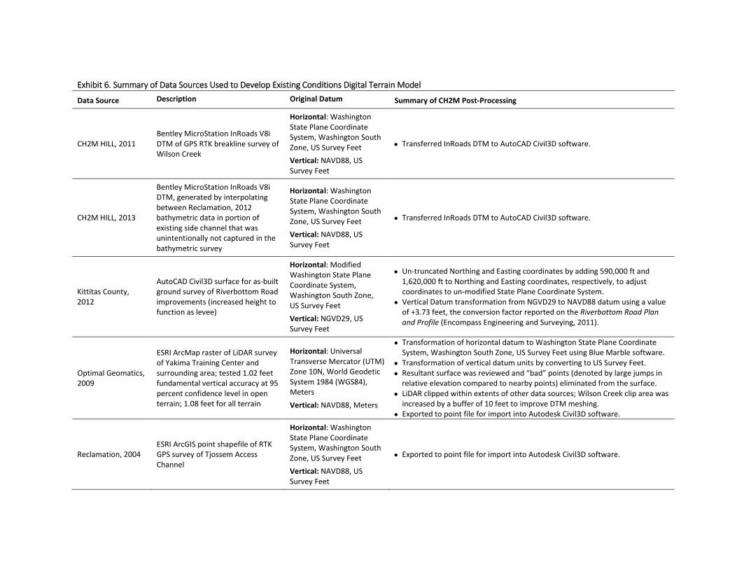
Data Source Description Original Datum Summary of CH2M Post-Processing
CH2M HILL, 2011 Bentley MicroStation InRoads V8i DTM of GPS RTK breakline survey of Wilson Creek
Horizontal: Washington State Plane Coordinate System, Washington South Zone, US Survey Feet Vertical: NAVD88, US Survey Feet
• Transferred InRoads DTM to AutoCAD Civil3D software.
CH2M HILL, 2013
Bentley MicroStation InRoads V8i DTM, generated by interpolating between Reclamation, 2012 bathymetric data in portion of existing side channel that was unintentionally not captured in the bathymetric survey
Horizontal: Washington State Plane Coordinate System, Washington South Zone, US Survey Feet Vertical: NAVD88, US Survey Feet
• Transferred InRoads DTM to AutoCAD Civil3D software.
Kittitas County, 2012
AutoCAD Civil3D surface for as-built ground survey of Riverbottom Road improvements (increased height to function as levee)
Horizontal: Modified Washington State Plane Coordinate System, Washington South Zone, US Survey Feet Vertical: NGVD29, US Survey Feet
• Un-truncated Northing and Easting coordinates by adding 590,000 ft and 1,620,000 ft to Northing and Easting coordinates, respectively, to adjust coordinates to un-modified State Plane Coordinate System. • Vertical Datum transformation from NGVD29 to NAVD88 datum using a value
of +3.73 feet, the conversion factor reported on the Riverbottom Road Plan and Profile (Encompass Engineering and Surveying, 2011).
Optimal Geomatics, 2009
ESRI ArcMap raster of LiDAR survey of Yakima Training Center and surrounding area; tested 1.02 feet fundamental vertical accuracy at 95 percent confidence level in open
Horizontal: Universal Transverse Mercator (UTM) Zone 10N, World Geodetic System 1984 (WGS84), Meters
• Transformation of horizontal datum to Washington State Plane Coordinate System, Washington South Zone, US Survey Feet using Blue Marble software. • Transformation of vertical datum units by converting to US Survey Feet. • Resultant surface was reviewed and “bad” points (denoted by large jumps in
relative elevation compared to nearby points) eliminated from the surface. • LiDAR clipped within extents of other data sources; Wilson Creek clip area was
terrain; 1.08 feet for all terrain Vertical: NAVD88, Meters increased by a buffer of 10 feet to improve DTM meshing. • Exported to point file for import into Autodesk Civil3D software.
Horizontal: Washington
Reclamation, 2004 ESRI ArcGIS point shapefile of RTK GPS survey of Tjossem Access Channel
State Plane Coordinate System, Washington South Zone, US Survey Feet Vertical: NAVD88, US
• Exported to point file for import into Autodesk Civil3D software.
Survey Feet
Exhibit 6. Summary of Data Sources Used to Develop Existing Conditions Digital Terrain Model

Exhibit 6. Summary of Data Sources Used to Develop Existing Conditions Digital Terrain Model
Data Source Description Original Datum Summary of CH2M Post-Processing
Horizontal: Washington State Plane Coordinate
Reclamation, 2006 ESRI ArcGIS point shapefile of RTK GPS survey of Tjossem Ditch
System, Washington South Zone, US Survey Feet Vertical: NAVD88, US Survey Feet
• Exported to point file for import into Autodesk Civil3D software.
Reclamation, 2007
ESRI ArcGIS point shapefile of user-generated points to adjust LiDAR surface over select areas of open water to reflect observed side channel and river bottom or in-channel features not reflected in survey (e.g., LWM)
Horizontal: Washington State Plane Coordinate System, Washington South Zone, US Survey Feet Vertical: NAVD88, US Survey Feet
• Exported to point file for import into Autodesk Civil3D software.
Reclamation, 2012
ESRI ArcGIS point shapefile of single-beam bathymetric data of Yakima River bathymetry through Schaake Reach and RTK GPS survey of shallow areas, such as point bars
Horizontal: Washington State Plane Coordinate System, Washington South Zone, US Survey Feet Vertical: NAVD88, US Survey Feet
• One point removed with approval of surveyor due to large relative difference from neighboring points. • Exported to point file for import into Autodesk Civil3D software.

Reported Phosphorous Concentration (mg/kg)
Side Channel 1
Side Channel 2
Side Channel 3 Reinvigorated side channels
Reported Phosphorus Concentration (mg/kg) Side channel feature
0 - 100 continues to south
100 - 399 Side channel alignments proposed by 399 - 999 Hilldale (2007); locations approximate.
>1000
Notes: Exhibit 7. Results of Soil Phosphorus1. Phosphorus levels of more than 100 mg/kg are considered "excessive," according to the Soil Test Interpretation Guide (Marx Sampling Data (from Land Profile, Inc., 2007) et al., 1999, as cited in Land Profile, Inc., 2007). Basis of Design Report
2. Side Channel alignments approximate, as they were hand-digitized Schaake Property Habitat Improvement Projectfor illustration purposes only. DRAFT October 21, 2015


Dis
char
ge a
t ELN
W H
ydro
ME
T G
age
(cfs
)1
25000
20000
15000
10000
5000
0
July 9
Minimum Measured
1976 to 2012 Average
Maximum Measured
November 1
Anticipated Construction Window
Month (Organized by Calendar Year) Notes Exhibit 8. Mean Daily Discharge for 1 Primary purpose of gage is to time irrigation diversions; as such, gage rating curve ELNW Hydromet Gage, 1976 to 2012 is no longer calibrated at high discharges. High discharge measurements should Basis of Design Report not be considered reliable (Kreuter, 2014). Schaake Property Habitat Improvement Project
DRAFT October 21, 2015

Related Documents