Scenario Analyses for 2050 Carbon Neutrality in Japan (Interim Report) Advisory Committee for Natural Resource and Energy Strategic Policy Committee May 13 th , 2021 Acknowledgement: We thank Dr. Yuji Matsuo, the Institute of Energy Economics, Japan, for his cooperation on the integration cost analysis of power grid. Keigo Akimoto, Fuminori Sano Systems Analysis Group Research Institute of Innovative Technology for the Earth (RITE) Some additional data is added to the original material. (Ver. June 11 th , 2021)

Welcome message from author
This document is posted to help you gain knowledge. Please leave a comment to let me know what you think about it! Share it to your friends and learn new things together.
Transcript

Scenario Analyses for 2050 Carbon Neutralityin Japan (Interim Report)
Advisory Committee for Natural Resource and EnergyStrategic Policy Committee
May 13th, 2021
Acknowledgement: We thank Dr. Yuji Matsuo, the Institute of Energy Economics, Japan, for his cooperation on the integration cost analysis of power grid.
Keigo Akimoto, Fuminori SanoSystems Analysis GroupResearch Institute of Innovative Technology for the Earth (RITE)
Some additional data is added to the original material. (Ver. June 11th, 2021)

1. Overview of Climate Change Mitigation for Carbon Neutrality

3
Image of Primary Energy in Japan for Net Zero Emissions (1/2)
Use of overseas renewables (green hydrogen) (import of hydrogen, ammonia, and syn. fuels (CCU))
Use of renewables surplus for hydrogen
Use of overseas CO2 reservoir (pre-combustion CO2capture) (import of blue hydrogen (incl. ammonia))
BECCS, DACCS Forestation, mineralization (concrete CCU)
Fossil fuels w/o CCS
Decarbonized
energy
Remaining fossil fuels
Fossil fuels + CCS
Renewable energy
Nuclear
【Use of overseas resources】
【Domestic primary energy supply】
Energy saving or Reduction in embodied energy of goods/services(incl. Society 5.0)
Negative emission technologies (NETs)
Domestic renewables
Measures of grid to expand renewables (incl. storage battery)
Sys. fuels prone to be generated from fossil fuels if the constraint on CO2 is loose in the producing countries, while from BECCS or DAC (with increased cost) if the constraint is strict.
Fossil fuels w/CCS
Nuclear
Use of overseas CO2reservoir (post-combustion)
Domestic CO2 storage
【Use of overseas resources】
The model analyses represent consistent energy structures and costs which are economically rationalized with cost minimization under assumed conditions of technologies.
【Assessment Scenarios】 The limit on nuclear power is
assumed as a social constraint. The constraint of CO2 storage
potential is also assumed.
In this case, the ratio among domestic renewables, overseas hydrogen / ammonia / syn. fuels is derived with cost minimization criterion (the solution suggested by the model is not so flexible).

4
Source) Strategic Policy Committee, Advisory Committee for Natural Resource and Energy, 2020
The whole system including non-electric power sectors is analyzed in the model. Electricity generation amount is determined by combined factors such as followings: energy demand
change induced by social structural change (basically although it depends on socio-economic pathways] + [electrification increase by energy usage structural change ( )] + [demand decrease by power saving ( )] + [electrification of non-electricity demand ( )] + [increase of loss in increased power storage, e.g., storage battery, due to VRE expansion ( )] + [increase of electricity demand to produce green hydrogen and e-fuels (syn. fuels) ( ) (however, electricity demand in Japan would not be affected in case of overseas manufacturing)].
Image of Primary Energy in Japan for Net Zero Emissions (2/2)
Commercial/Residential0.11Gt
Industry0.3Gt
Transport0.2Gt
20181.06Gt
0.45Gt
Non-electricity
Electricity
Carbon removal
Industry0.33Gt
Transport0.15Gt
0.36Gt
Residential & Commercial0.09Gt
20300.93Gt (▲25%)
2050Net-zero emission
(▲100%)
Electrification
Hydrogen (hydrogen-based reduced iron, FCV, etc.)
Methanation, syn. fuels
Forestation, DACCS, etc.
Non-fossil sourcesRenewables
NuclearThermal + CCUS /
Carbon recycleHydrogen / Ammonia
Maximize CCUS / carbon recycle, etc. in the sectors where decarbonization by electrification / hydrogenation is not possible.
* The figures indicate CO2 from energy sources.
Biomass

2. Assessment using Global Energy and Climate Change Mitigation
Model: DNE21+
The model-driven scenarios represent quantitative features of energy and global warming response measures which are globally consistent in a given time-frame under assumed conditions, and specify the energy systems which are economically rationalized with cost minimization.

Energy Assessment Model: DNE21+(Dynamic New Earth 21+)
Systemic cost evaluation on energy and CO2 reduction technologies is possible. Linear programming model (minimizing world energy system cost; with 10mil. variables and
10mil. constrained conditions) Evaluation time period: 2000-2100
Representative time points: 2005, 2010, 2015, 2020, 2025, 2030, 2040, 2050, 2070 and 2100 World divided into 54 regions
Large area countries, e.g., US and China, are further disaggregated, totaling 77 world regions. Interregional trade: coal, crude oil/oil products, natural gas/syn. methane, electricity, ethanol,
hydrogen, CO2 (provided that external transfer of CO2 is not assumed in the baseline) Bottom-up modeling for technologies on energy supply side (e.g., power sector) and CCUS For energy demand side, bottom-up modeling conducted for the industry sector including steel,
cement, paper, chemicals and aluminum, the transport sector, and a part of the residential & commercial sector, considering CGS for other industry and residential & commercial sectors.
Bottom-up modeling for international marine bunker and aviation. Around 500 specific technologies are modeled, with lifetime of equipment considered. Top-down modeling for others (energy saving effect is estimated using log-term price elasticity.
• Regional and sectoral technological information provided in detail enough to analyze consistently.• Analyses on non-CO2 GHG possible with another model RITE has developed based on US EPA’s assumptions.
6
• Model based analyses and evaluation provide recommendation for major governmental policy making on climate change, e.g., cap-and-trade system and Environmental Energy Technology Innovation Plan, and also contribute to IPCC scenario analysis.

Technology Descriptions in DNE21+
Fossil fuelsCoal (coal, lignite)Oil (conventional, unconv.)Gas (conventional, unconv.)
Cumulative production
Unitproductioncost
Renewable energiesHydro power & geothermalWind power PV / CSPBiomass, Marine energy
Annual production
Unitsupplycost
Nuclear power
Energy conv.processes(oil refinery,
coal gasification,bio-ethanol,
gas reforming,water electrolysis,
etc.)
Industry
ElectricPower
generation
CCUS
Transport
Residential & Commercial
Iron & steel
Cement
Paper & pulpChemical (ethylene, propylene, ammonia)
Aluminum
Vehicle, shipping, aviation
Air conditioner, refrigerator, TV, etc.
Solid, liquid and gaseous fuels, and electricity
Solid, liquid and gaseous fuels, and electricity
Solid, liquid and gaseous fuels, and electricity
7
For main sectors modeled in a bottom-up way, economic activities and service demands (e.g., production of crude steel and cement, passenger service demand) are exogenously assumed.
Oil prices in baseline assuming no climate measures are exogenously assumed, and other price factors, e.g., unit production costs, concession fees, are adjusted. In emission reduction case, prices are endogenously decided accordingly.
Facility cost and efficiency of each technology are exogenously assumed.
DAC

Limitation and Challenge of the Model8
In DNE21+ model, which enables the assessment of the whole world with consistency regarding energy import / export amounts and prices, the prerequisites are assumed considering consistency in the global system. Regarding the assumption for PV, wind power generation and CO2 storage potential, for instance, the potentials for each country are assumed using a common assumption logic based on the global GIS data.
Therefore, it is suitable for the comparison and assessment of technological and economic potentials among countries while it does not significantly consider country-specific circumstances (e.g., social and physical constraints on nuclear power and renewable energy in Japan).
In-depth analyses for Japan should be conducted separately taking into account moredetailed conditions. For instance, the domestic power grid structure is not specified in DNE21+, making difficult to assess the differences in system costs depending on the renewable energy installation sites.
Analysis results of Power Generation Mix Model by Univ. of Tokyo and IEEJ is utilized.
As DNE21+ is a dynamic optimization model, it can provide assessment for time points, e.g., 2050, in accordance with the future features in 2100. Also, any arbitrary scenario assumption is supposed to be excluded as the assessment is made based on a cost minimization criterion. On the other hand, the model could show extreme changes, e.g., all the predicted technologies are replaced with others once economic rationality is completed. (The real world usually follows a technology diffusion curve without extreme changes as there are various actors. Compared to macro econometric models, which is superior for representing such situations, this type of optimization models could sometimes show extreme changes.)

9
Assumption of Integration Cost:Power Generation Mix Model by Univ. of Tokyo and IEEJ
As DNE21+ is a global model and not suitable for the analysis regarding internal power grid and regional conditions of renewable energy, it applies the results of the study on the assumption of integration cost under high VRE penetration based on an optimal power generation mix model, by Fujii-Komiyama Laboratory, the University of Tokyo and the Institute of Energy Economics, Japan1), 2).
Time fluctuation of VRE output is modeled based on nationwide meteorological data, e.g., AMeDAS, to estimate the optimal configuration (power generation and storage system) and the annual operation by linear programming.
Calculated with hourly modeling by 5 divided regions (Hokkaido, Tohoku, Tokyo, Kyushu and others). Prerequisites for power generation cost, resource constraint, etc, are defined in line with DNE21+.
1) R. Komiyama and Y. Fujii, (2017). Energy Policy, 101, 594-611.2) Y. Matsuo et al., (2020). Applied Energy, 267, 113956.
Meteorological data(AMeDAS: 1300 nodes)
Output example of PV Output example of wind power
Considered in modeling・・・ Output control, power storage system (pumped hydro, lithium-ion battery and hydrogen storage),reduction of power generation facility utilization, inter-regional power transmission lines, electricity loss in storage and transmission
Not considered in modeling・・・ Intra-regional power transmission lines, power grid, influence of decrease of rotational inertia, grid power storage by EV, prediction error of VRE output, supply disruption risk during dark doldrum
Acknowledgement: We thank Dr. Yuji Matsuo, the Institute of Energy Economics, Japan, for his cooperation.

10
Sector Assumption method Example SupplementaryPopulation UN median estimate Refer to
appendixAs DNE21 is an energy system model, population and GDP are exogenous and used for the assumption such as for service demand.
GDP Estimated by country based on assumed population, GDP per capita, etc. Consistent with IPCC SSPs scenarios.
Service demand, etc.
Iron & steel,Cement,Chemical,Paper & pulpAluminum,Road transportation,Domestic
aviation, International
aviation, International
marine bunker
Assumed by country / region divided in the model based on past records, population, GDP, etc.For iron & steel, total production of crude steel is assumed, and also, as its internal number, electric furnace steel production assumed based on the available iron scrap estimate.For chemical, ethylene, propylene, BTX and ammonia are assumed.For road transportation, demands are assumed by car (small and large), bus and truck (small and large). For aviation, demands by 4 flight zones are assumed.
Refer to appendix for selected sectors
Service demand can be significantly reduced in the case that GDP losses are huge due to high costs of emission reduction or that there are large differences in countermeasure cost among nations. It should be noted that the feedback in such cases are not considered in DNE21+ as it is a partial equilibrium model.
Prerequisites and Assumptions in DNE21+ Model (1/4)

11
Sector Assumption method Example SupplementaryFossil fuel Amount of
resourcesBased on the reports of United States Geological Survey (USGS) for oil / gas, and World Energy Council (WEC) (Survey of Energy Resources 1998) for coal.Assumed from the article by H-H. Rogner (1997) for unconventional oil / gas.
Globally, conventional oil (incl. NGL): 241 Gtoe, conventional natural gas: 243 Gtoe, coal (incl. lignite): 2576 Gtoe, etc.
Price Based on the article by H-H. Rogner (1997) for mining cost. FOB price in baseline scenario is adjusted as concession fee referring to IEA WEO, etc.
Refer to appendix
Biomass Residue Food residue and wood residue are estimated by country. Potential in 2050 is about 9EJ/yr globally.
Plantation and forestation potential
Using RITE GLaW (Grid-based model for agricultural Land-use and Water resource assessment) model, potentials are estimated for food production according to food consumption and meteorological forecast, land-use areas and surplus land. Potential for plantation biomass (and forestation) is estimated.
About 900 Mha is available in 2050 globally.
Hydrogen Several production technologies are assumed, such as produced from fossil fuel (grey hydrogen), fossil fuel + CCS (blue hydrogen) and by renewable energy (green hydrogen), and the model endogenously decides the one with minimized cost under the emission reduction target. Transportation cost is modeled referring to a reported case of liquid hydrogen transportation cost, provided that long-distance transportation is not specified.
Refer to appendix For methanation, Sabatier reaction and SOEC co-electrolysis are assumed.
Synthetic fuel (CCU)
Petroleum-based synthetic oil and synthetic methaneare assumed. CO2 from biomass, DAC, and fossil fuel is assumed. The model endogenously decides the one with minimized cost under the emission reduction target.
Prerequisites and Assumptions in DNE21+ Model (2/4)
12
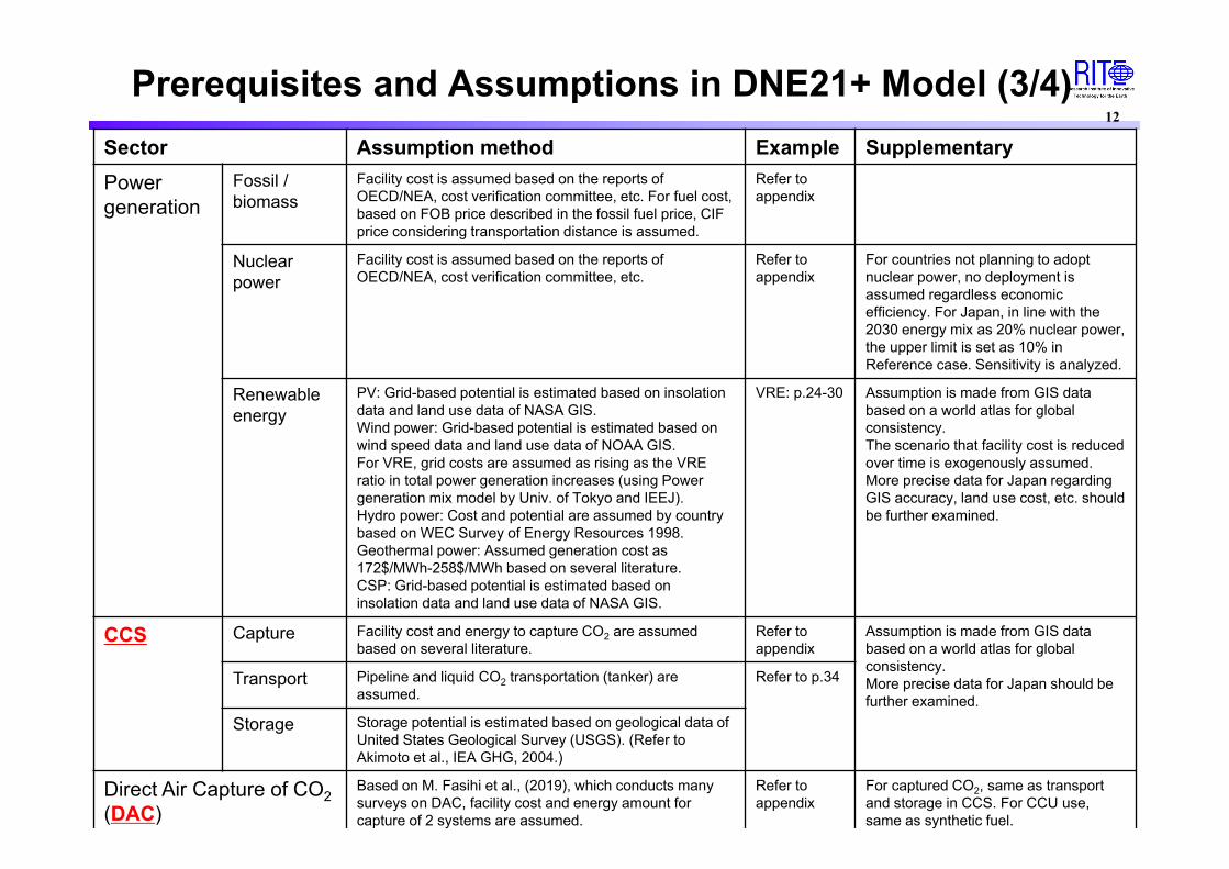
Sector Assumption method Example SupplementaryPower generation
Fossil / biomass
Facility cost is assumed based on the reports of OECD/NEA, cost verification committee, etc. For fuel cost, based on FOB price described in the fossil fuel price, CIF price considering transportation distance is assumed.
Refer to appendix
Nuclear power
Facility cost is assumed based on the reports of OECD/NEA, cost verification committee, etc.
Refer to appendix
For countries not planning to adopt nuclear power, no deployment is assumed regardless economic efficiency. For Japan, in line with the 2030 energy mix as 20% nuclear power, the upper limit is set as 10% in Reference case. Sensitivity is analyzed.
Renewable energy
PV: Grid-based potential is estimated based on insolation data and land use data of NASA GIS.Wind power: Grid-based potential is estimated based on wind speed data and land use data of NOAA GIS.For VRE, grid costs are assumed as rising as the VRE ratio in total power generation increases (using Power generation mix model by Univ. of Tokyo and IEEJ).Hydro power: Cost and potential are assumed by country based on WEC Survey of Energy Resources 1998.Geothermal power: Assumed generation cost as 172$/MWh-258$/MWh based on several literature.CSP: Grid-based potential is estimated based on insolation data and land use data of NASA GIS.
VRE: p.24-30 Assumption is made from GIS data based on a world atlas for global consistency.The scenario that facility cost is reduced over time is exogenously assumed.More precise data for Japan regarding GIS accuracy, land use cost, etc. should be further examined.
CCS Capture Facility cost and energy to capture CO2 are assumed based on several literature.
Refer to appendix
Assumption is made from GIS data based on a world atlas for global consistency.More precise data for Japan should be further examined.
Transport Pipeline and liquid CO2 transportation (tanker) are assumed.
Refer to p.34
Storage Storage potential is estimated based on geological data of United States Geological Survey (USGS). (Refer to Akimoto et al., IEA GHG, 2004.)
Direct Air Capture of CO2(DAC)
Based on M. Fasihi et al., (2019), which conducts many surveys on DAC, facility cost and energy amount for capture of 2 systems are assumed.
Refer to appendix
For captured CO2, same as transport and storage in CCS. For CCU use, same as synthetic fuel.
Prerequisites and Assumptions in DNE21+ Model (3/4)

13
Sector Assumption method Example Supplementary
Industry Iron & Steel Energy saving technologies (e.g., COURSE50), CCS, gas-based DRI, and H2-based DRI are assumed. Facility cost and energy balance are assumed referring to several literature (J. Oda et al., Energy Economics, 2007, etc.).The installation amount of electric furnace is constrained according to availability of scrap iron.
Refer to appendix for availability of H2-based DRI and scrap iron.
By BF-BOF + CCS, about 30% CO2emission reduction is possible, but net-zero emission is not possible.
Cement / Concrete
Energy saving technologies, conversion from coal to gas, hydrogen or synthetic methane, CCS (only available above 3000 t-clinker/day) are assumed, which are endogenously determined with total optimization. Facility cost and energy balance are assumed referring to several literature. Concrete CCU is assumed.
Concrete CCUMax. 1.9kgCO2/t-cement (net absorption considering the CO2 amount by natural absorption is modeled.)
Chemical Methods to produce ethylene, propylene, BTX and ammonia are assumed, as well as energy saving technologies for each. Production of ethylene and propylene from ethane, and production of ethylene, propylene and BTX via methanol (produced from hydrogen and CO2(CCU)) are also assumed.
Residential & Commercial
Residential & Commercial
Assuming demands for refrigerator, lighting, cooking equipment, hot-water supply and cooling & heating, various equipment, e.g., heat pump and cogeneration, is modeled. City gas infrastructure cots is also assumed.
Transport infrastructure cost to convert from city gas to hydrogen is assumed as twice as from gas and syn. methane.
Transport Road transportation
Conventional engine car (gasoline, light oil and bio fuel), HV, PHV, EV and FCV are assumed by vehicle type (passenger car (small / large), bus and truck (small / large)). Car body price is assumed referring to sales price and cost reduction outlook. Additional costs for infrastructure for EV and FCV are assumed (hugely decreasing toward 2050). Syn. Fuels are assumed. Share mobilities (car-/ride-sharing) scenario induced by fully autonomous car is also assumed.
Refer to appendix for the example of small passenger car.Refer to p.36 for car-/ride-sharing scenario assumption.
It is assumed that fully autonomous car is available in 2030 in share mobilities scenario.
Aviation Energy saving, transition of jet fuel to biofuel / syn. jet fuel, hydrogen aircraft and electric aircraft are assumed. The scope that technologies can meet the demand by flight zone is assumed. Fuel cost is endogenously determined in the model. Aircraft cost is assumed referring to several literature.
International marine bunker
Heavy oil, light oil, biodiesel fuel, LNG carrier and hydrogen ship are assumed.
Prerequisites and Assumptions in DNE21+ Model (4/4)

-40
-20
0
20
40
60
80
2000 2010 2020 2030 2040 2050 2060 2070 2080 2090 2100
CO
2 em
issi
ons
[GtC
O2/
yr]
HistoricalBaseline2DS(▲40% GHG in 2050)B2DS(▲70% GHG in 2050)Below 1.5℃ in 2100 (>66%)
-20
0
20
40
60
80
100
120
2000 2010 2020 2030 2040 2050 2060 2070 2080 2090 2100
GH
G e
mis
sion
s[G
tCO
2eq/
yr]
HistoricalBaseline2DS(▲40% GHG in 2050)B2DS(▲70% GHG in 2050)Below 1.5℃ in 2100 (>66%)
14
Global Baseline Emissions andAssumed Emissions Scenarios under 2C and 1.5C
※ 2DS, B2DS, B1.5OS scenarios assume emission constraints equivalent to NDCs of each nation up to 2030
GHG emissions
CO2 emissions
Note) Emissions for baseline shows model estimates results under SSP2, not assumed scenario
Net zero CO2 emissionsaround 2100
Net zero CO2 emissionsaround 2060
Net zero GHG emissionsaround 2100
Net zero CO2 emissions around 2050
Net zero GHG emissionsaround 2065
In the scenario analyses of Japan’s 2050 carbon neutrality, 1.5C global scenarios are assumed in addition to Japan’s emissions reduction scenarios, for the global competition for carbon neutral resources to be considered.

3. Assumed Scenarios

16Overview of Assumed Scenarios
GHG emission reduction in 2050
Technology assumption(cost / performance)
Technology deployment scenario
Reference case ▲100%
(For other than Japan, ▲100% for each western country, and ▲100% for the others as a whole)
Standard case
(Note: It is premised that RE is diffused due to suspected inertial force in high share RE scenario.)
Decided endogenously (cost minimization), with constraints for nuclear power up to 10% and CO2 storage.
Assuming high share RE in model’s standard assumption under Reference case
1Renewable Energy
100% (RE100)
Renewable energy nearly 100%(Nuclear power 0%)
Assuming each technology is further accelerated or expanded.
2Renewable Energy
Innovation
Acceleration of RE cost reduction
Decided endogenously, with constraints for nuclear power up to 10% and CO2storage.
3Nuclear Power
Utilization
Expansion of nuclear power deployment
Decided endogenously, with constraints for nuclear power up to 20% and CO2storage.
4Hydrogen Innovation
Acceleration of hydrogen cost reduction
Decided endogenously, with constraints for nuclear power up to 10% and CO2storage.
5CCUS Utilization
Expansion of CO2storage potential
Decided endogenously, with constraints for nuclear power up to 10%. Large CCS storage potential assumed.
6Demand
Transformation
Expansion of car-/ride-sharing
Dramatic expansion of car-/ride-sharing due to fully autonomous car implementation assumed.Other assumptions are same as Reference case.
*As for demand side transformation, scenario analyses will be continued including other factors than car-sharing.

Scenario Description in Modeling Analyses (1/4)17
Scenario Challenges to realize scenario Model Input
Reference case
Scenario in which the challenges of each power source to realize Reference case, presented for deeper discussion in the 35th Strategic Policy Committee, are overcome.
Image of power generation mixRE 50-60%, Nuclear power 10%, Hydrogen / Ammonia 10%, CCUS thermal 20-30%
Determined in the model with cost minimization
<Renewable energy>(1) Securing load balanceFor VRE expansion, need to secure demand & supply balance to cope with output fluctuation due to natural conditions.(2) Securing transmission capacityNeed to promote large-scale capital investment and local consensus for construction to increase the transmission capacity that connects areas potential for deployment of renewables and areas in demand.(3) Securing inertial forceNeed to secure a constant “inertial force” (to keep turbines rotating) in an entire system to prevent blackout due to accidents such as power loss.(4) Response to natural conditions and social constraintsFor RE expansion under disadvantageous natural conditions in terms of insolation and wind, e.g., flat land excluding forests is half that of Germany and shallow sea area is 1/8 that of the UK, need coordination with local community and concerned parties, considering the impact on environment, ecosystem, shipping routes, etc.(5) CostAdditional costs can be required for land preparation, connection and coordination if the deployment amount increases under the geographical conditions such as scarce flat land and shallow sea. Need to reduce the total RE deployment costs by securing suitable sites and developing highly efficient power generation equipment.
<Renewable energy>Assumption for stable grid operation• Assuming VRE expansion by overcoming the challenges,
such as securing power demand & supply balance, securing transmission capacity to deal with unevenness of RE suitable sites, and securing inertial force in an entire system to cope with blackout in case of power loss.
Assumption for deployment based on natural / physical conditions• Assuming power generation amount above the current
Germany’s (about 640TWh) and above 2 times of UK’s (about 330TWh) under limited natural conditions.
• Assuming power generation amount based on the case that solar and offshore wind power deployment expands by installing PV on rooftops or in abandoned croplands and utilizing Act of Promoting Utilization of Sea Areas.
Economic assumption• Assuming that capital cost and O&M cost be reduced
according to the international price as securing suitable sites progresses with the current technological level (provided that cost increase due to location restriction is not precisely considered).
Assumed power generation costs are PV: ¥10-17, wind power: ¥11-20 and integration cost: about ¥4.
<Nuclear power>(1) Restoring public trustNeed to restore public trust through pursuing safety, coexisting with local community, establishing sustainable back-end system, improving feasibility, maintaining and strengthening human resources / technologies / industrial bases, and working on nuclear power innovation.(2) Securing installed capacityThe installed capacity of nuclear power will decrease significantly after 2040 to be 23.74GW (166.3TWh) (about 10% of power generation mix) in 2050, and 9.56GW (67TWh) in 2060, even assuming that all 36 nuclear plants (incl. under construction) operate for 60 years. Need to secure installed capacity.
<Nuclear power>Assumption for sustainability• Assuming power generation amount in the conditions that
nuclear power is continuously utilized on a certain scale and new reactors are commissioned by tackling issues such as safety improvement, final disposal site problem and nuclear fuel cycle.
Economic assumption• For power generation cost, the global standard is used on
the premise of the current technological level.Power generation amount is constrained up to 10% of the power generation mix considering social restrictions.Assumed power generation cost is ¥13, same as global standard .

18
Scenario Challenges to realize scenario Model Input
Reference case
Scenario in which the challenges of each power source to realize Reference case, presented for deeper discussion in the 35th Strategic Policy Committee, are overcome.
Image of power generation mixRE 50-60%, Nuclear power 10%, Hydrogen / Ammonia 10%, CCUS thermal 20-30%
Determined in the model with cost minimization
<Hydrogen / Ammonia>(1) Supply sideConsidering supply is highly likely prioritized in the sectors where electrification is difficult, such as industrial, residential & commercial, and transportation, need to secure about 20Mt of hydrogen in Japan.If domestic procurement is not enough, need to develop transportation technologies and port facilities for large-scale and low-cost import.(2) Demand sideIn developing combustors to ensure stable combustibility of hydrogenand ammonia power generation, need technological development to ensure suppression of NOx generation and stable combustibility.
For expanding demand & supply of hydrogen and securing the supply amount used for power generation, need to expand the demand in other sectors than power generation, e.g., FC truck and hydrogen ship in transportation and expanded usage in industry.(3) CostIn the context that hydrogen supply chain has not been established, need to reduce the costs of cargo bases and liquefied hydrogen carriers in addition to the costs required for hydrogen production and liquefaction.
<Hydrogen / Ammonia>Assumption for technological development• A major premise is to overcome technical issues for
hydrogen / ammonia power generation.
Assumption for large-scale procurement• On top of that, it is assumed that after being used
preferentially in industrial / residential & commercial / transportation sectors, the supply greatly exceeding the 2030 forecast should be secured. (LNG needs to increase at a higher pace than quadruple incremental rate of supply in 30 years from 1980s to 2010s.)
Economic assumption• Assuming manufacturing and transportation cost is
one fifth of about ¥170/Nm3 or less, on the premise that inexpensive manufacturing equipment and a global supply chain are developed.
Assumed power generation cost is ¥16-27.
<CCUS>(1) Technology / CostNeed to develop efficient technology to separate and capture CO2, establish low-cost CO2 transportation technology, and reduce storage cost. Also, for practical use of carbon recycle, need cost reduction and application enhancement.
If domestic CCUS is not enough to handle, for transportation overseas, need to overcome further technical issues such as establishing ship transportation technology for low-temperature and low-pressure liquefied CO2, which is unprecedented in the world yet.
(2) Securing potential sites and expanding applicationConsidering CCUS is highly likely applied for electrification in industrial / residential & commercial / transportation sectors or for GHG emissions from the sectors where utilizing hydrogen / ammonia is difficult, need to secure substantial suitable lands and application development in order to utilize CCUS for power generation.
<CCUS>Assumption for technological development• Overcoming technical issues for practical use of CCS
and carbon recycling, e.g., technology to improve separation and storage efficiency, is a major premise. Assuming the cost will be reduced to 70% or less of the current level through technological development.
Assumption for large-scale storage• On top of that, it is assumed that after being used
preferentially in industrial / residential & commercial / transportation sectors and for non-energy sources, CCS will be implemented in excess of about 0.3Gt / year. In Reference case, assuming it possible to transport about 0.2Gt overseas.Assumed power generation cost is around ¥12.
In Reference case, CCS storage potentials are 90 MtCO2 in domestic and 240 MtCO2 overseas.
Scenario Description in Modeling Analyses (2/4)

19
Scenario Challenges to realize scenario Model Input
1Renewable
Energy 100%
Scenario in which carbon neutrality is realized with only RE.
<Renewable energy>In case that +40% (about 300TWh) or so of RE compared to Reference case is implemented, in addition to further securing load balance, transmission capacity and inertial force, the following capacity needs to be deployed additionally on the premise of the current technologies. If half of the capacity is realized by PV (about 150TWh) and another half by
offshore wind power (about 150TWh), the following amount is required. For PV, about 110GW (about 130TWh) is necessary in addition to Reference case.
If it is covered by 1 MW mega solar, additional 110,000 locations will be required, meaning, for instance, that all of the approximate 1,700 municipalities need to secure 65 sites on average additionally to the amount already deployed in Reference case.
For offshore wind power, the 2040 target amount of 45 GW (about 130TWh) is necessary in addition to Reference case.
The outlook for RE deployment in 2050 in the UK BEIS scenario* is about 400-430TWh, and about 2.5-2.7 times this amount needs to be deployed in RE 100% case.
Image of power generation mixRE 100%
RE volumes are exogenously assumed.
Power generation costSame as Reference case
2Renewable
Energy Innovation
Scenario in which RE installation expands due to dramatic reduction of RE cost and with the challenges of grid operation, e.g., natural & physical constraints and inertial force, overcome by innovation, more significantly compared to Reference case.
<Renewable energy>In order to realize further cost reduction than Reference case and tackle physical and social constraints, need to overcome technical issues through technological innovation, such as development and commercialization of innovative technologies, e.g., tandem solar cell and perovskite solar cell, and wind power with significantly improved power generation efficiency.For overcoming the problem of inertial force, need to develop and implement a system with suspected inertial force and apply inertial force in power storage system.
Also, if +10% (about 130TWh) is deployed additionally to Reference case, need to install the same RE setup as any shown in 1 Renewable Energy 100% case.
Image of power generation mixRE 60-70%
Power generation costRE cost: PV ¥6-10, Wind power ¥8-15Same as Reference case for other power sources
* BEIS, Net Zero and the Power Sector Scenarios, 2020.12
Scenario Description in Modeling Analyses (3/4)

20
Scenario Challenges to realize scenario Model input
3.Accelerated utilization of nuclear
power
A scenario in which replacement and new expansion are realized as a result of progressing public understanding of nuclear power and overcoming social and technical issues such as ensuring safety and establishing a back-end system
<Nuclear power>If all 36 units have been in operation for 60 years, it will be about 10%. To further increase it by 10%, approximately 20 new furnaces (20 million kW) are required through replacement or new expansion by overcoming issues such as restoration of public trust, understanding of local community, final disposal and establishment of back-end systems such as the nuclear fuel cycle.
Power generation mixNuclear power: 20%
Power generation costSame as the ReferenceCase
Upper limit20% for nuclear power
4.Dramatic reduction
in hydrogen/ammonia
prices
A scenario in which technological innovations in the hydrogen production and transportation process significantly reduce prices of hydrogen production and transportation
<Hydrogen/ammonia>Assuming a reference value case in which manufacturing and transportation costs are 1/5 or less from the current level, it is necessary to further reduce these costs by further technological innovation and market expansion through expansion of private investment.
In addition, if + 10% (about 130 billion kWh) is additionally introduced from the case of the reference value, it is necessary to additionally procure 5 to 10 million tons of hydrogen domestically or from overseas. If all are procured domestically, a total of 1,000 to 2,000 plants of the same scale as FH2R are required, and if all are procured from overseas, it is necessary to additionally secure about 90 vessels from the reference value,in which the hydrogen loading capacity of the vessel (currently about 75 tons per vessel) expands to about 100 times or more (about 10,000 tons per vessel) from the reference value.
Power generation mixHydrogen/ammonia: 20%
Power generation costHydrogen price: ¥20 – 35/Nm3 (Power generation cost ¥13 – 21/kWh)Other than hydrogen, costs are the same as Reference Case
5.Dramaticincreases
in CO2 storage in
CCUS
A scenario in which the amount of transportation is significantly increased by significantly expanding domestic storage areas through technological innovation and overcoming the challenges of overseas transportation of CO2.
<Thermal power generation with CCUS>Assuming a reference value case in which costs are less than half of the current levelbecause of technological development and market expansion, it is necessary to further expand the storage capacity by further technological innovation and market expansion through expansion of private investment.In addition, if + 10% (about 130 billion kWh) is additionally introduced from the case of the reference value, a total of 550 million tons of CCS storage is required. This means that a total of 600 drilling wells (injection rate of 500,000 tons / y per well) will be required for domestic storage by 2050. Moreover, it is necessary to realize a scale of CCS which is 900 times or more of the cumulative injection amount (300,000 tons in about 3 years) of the Tomakomai demonstration project every year. In addition, about 300 CO2 transport vessels (assumed to be 20,000t-CO2 / vessel) are required for overseas storage.
Power generation mixCCUS power generation: 30% - 40%
Power generation costSame as Reference Case
Upper limitDomestic storage for CCS:270 million tons, Overseas transportation volume expands to 280 million tons.
Scenario Description in Modeling Analyses (4/4)

21
Scenario Assumption and Share of Renewables in Total Electricity(in 2050)
ScenarioCost of
renewable energy
Ratio of nuclear power
Cost of hydrogen CCUS(Storage potential)
Fully autonomous driving
(Car ride sharing)
Share of RE in power mix
Reference Case*1
Standard cost
10%
Standard cost
Domestic storage:91MtCO2/yr,
Overseas transportation:235MtCO2/yr
Standard assumption(no fully autonomous
cars)
54%(Optimization results)
1. Renewable Energy 100%(RE 100)
0%Almost 100%(Assumption)
63%(Optimization results)
2. Renewable Energy Innovation
Low cost 10%
Domestic storage: 91MtCO2/yr,
Overseas transportation:235MtCO2/yr
3. Nuclear Power Utilization*2
Standard cost
20% 53%(Optimization results)
4. Hydrogen Innovation
10%
Hydrogen production such as water
electrolysis, hydrogen liquefaction facility
cost: Halved
47%(Optimization results)
5. CCUS Utilization
Standard cost
Domestic:273MtCO2/yr、
Overseas:282MtCO2/yr
44%(Optimization results)
Domestic: 91Mt,Overseas: 235Mt
Realization and diffusion of fully autonomous
driving and expansion of car ride sharing after
2030, and decrease in material production due
to reduction of the number of automobiles
51%(Optimization results)
6. Demand Transformation
*1:There is no feasible solution without DAC, and DAC is assumed to be available in all scenarios.*2:Nuclear power utilization scenarios up to a ratio of 50% are separately examined.
* Regarding changes on the demand side, further scenario analysis that takes into account factors other than car sharing will be conducted.

22 Each power source must overcome a large hurdle to achieve the reference values for power sources in 2050 as
presented at the Strategic Policy Committee. Under these conditions, for the 30 to 40% of nuclear power and fossil+CCUS, in case the upper limit of nuclear
power is 10%, it is necessary to cover 20-30% with fossill+CCUS, thus it is assumed a considerable amount of CO2 is stored at home/abroad including CCUS required amount other than the electric power sector. For hydrogen/ ammonia and carbon recycled fuel, it is assumed that infrastructure development, etc. is expected to execute a large-scale transportation without setting the upper limit of supply on the model.
It should be noted that in this analysis, the conditions were set by mechanically assuming such CCS storage amount based on the above reference values.
【ref.】Concept of Innovation in Power Supply Ref. Value
2020/12/21 Strategic Policy Committee Material
In order to aim for carbon neutrality in 2050, stable power supply from decarbonized power sources is indispensable. From the perspective of 3E+S, multiple scenarios will be analyzed without limiting to the following. In deepening the discussion, the positioning of each power source is suggested as follows.
Esta
blis
hed
deca
rbon
ized
po
wer
sou
rce
Renewable Energy ・ Continue to aim for maximum introduction as the main power source in 2050.・ Immediately work on issues to promote the maximum introduction such as adjustment amount, transmission capacity, ensuring inertial force, responding to natural conditions and social constraints, maximizing cost control, and increasing social transformation to cost increases.・ How about deepening discussions on covering 50-60%(approx.) of the generated power (* 1) with renewable energy in 2050 as a reference value (* 2)?
Nuclear power ・As an established decarbonized power source, aim for a certain scale of utilization on the premise of safety.・ In order to restore public trust, make an increased effort to improve safety, gain understanding and cooperation of the locationarea, solve back-end problems, secure business feasibility, maintain human resources and technical capabilities, etc. How about deepening discussion on covering 30-40% (approx.) with nuclear power which is a carbon-free power source other than renewable energy and hydrogen/ammonia, along with fossil+CCUS/carbon cycle in 2050 as a reference value (* 2)?
Pow
er s
ourc
es re
quire
d in
nova
tion
Ther
mal
pow
er
Fossil + CCUS ・ While having the advantages of supply capacity, adjustment power, and inertial force, decarbonization of fossil-fired power is the disadvantage.・Aim to utilize on a certain scale iimmediately by developing technology and suitable sites, expanding applications and reducing cost, etc., toward the implementation of CCUS / carbon recycling. How about deepening discussion on covering 30-40% (approx.) together with nuclear power which is a carbon-free power source other than renewable energy and hydrogen/ammonia in 2050 as a reference value (* 2)?
Hydrogen, Ammonia
・While having the advantages of adjusting power and inertial force without emitting carbon during combustion, the challenges are establishing technology for large-scale power generation, reducing costs, and securing supply. Aim to build a stable supply chain immediately by promoting co-firing of gas-/coal-fired power, increasing supply and demand.・Aim for a certain scale of utilization as a carbon-free power source, taking into account competition with industrial and transportation demand. Based on the fact that procurement required for future power generation is estimated to be 5-10-million ton as basic hydrogen strategy, how about deepening discussion on covering 10% (approx.) of generated power with hydrogen/ammonia in 2050 as a reference value (* 2)?
*1: The amount of power generated in 2050 will be about 1.3-1.5 trillion kwh as a reference value (* 2) based on the power generation estimation by RITE presented at "the 33rd Strategic Policy Committee". *2: This is not as a government goal, this is one guideline / option for future discussions. This will be the one of options to deliberate in considering multiple scenarios in the future.

23
Under the medium socio-economic scenario SSP2 (see appendix), Direct Air CarbonCapture and Storage (DACCS), which realizes negative emission reduction, is anecessary condition for realizing carbon neutrality in Japan in 2050. Furthermore, ouranalysis shows that hydrogen direct reduction steelmaking in the iron and steelsector needs to be put into practical use by 2050, or the domestic CO2 storagecapacity in 2050 needs to be larger than 91 MtCO2/year that is assumed as standard.(reported at the Green Innovation Strategy Meeting in November, 2020)
Therefore, in all the scenarios, it is assumed that DACCS and hydrogen direct reduction steelmaking will be available by 2050.
【ref.】Conditions to Realize Carbon Neutrality in Japan by 2050
(Source) Document from the Green Innovation Strategy Meeting (November, 2020)

0
50
100
150
200
250
300
350
2010 2015 2020 2025 2030 2035 2040 2045 2050
発電
コス
ト[$
/MW
h]
屋根置太陽光(標準シナリオ):下限
屋根置太陽光(標準シナリオ):上限
屋根置太陽光(低位シナリオ):下限
屋根置太陽光(低位シナリオ):上限
0
50
100
150
200
250
300
350
2010 2015 2020 2025 2030 2035 2040 2045 2050
発電
コス
ト[$
/MW
h]
大型太陽光(標準シナリオ):下限
大型太陽光(標準シナリオ):上限
大型太陽光(低位シナリオ):下限
大型太陽光(低位シナリオ):上限
24
Assumption for Solar PV Power Generation Costs in Japan:Time Series
Cost and potential curve in 2050 is given on page 28.
Rooftop solar PV power generation Large-scale solar PV power generation
Marginal cost increases as introduction expands
Integration cost
Assumption on integration costis given on page 30.
*It should be noted that this is the average cost of the facility stock installed at each point in time, and is not the cost limited to new facility installed at that point in time. (Note) The gradation part is just an image of model calculation.
Cost range of rooftop solar PV in Standard scenario
Cost reduction overtime
Cost range of large-scale solar PV in Standard scenario
Cost range of large-scalesolar PV in Low cost scenario
Cost range of rooftop solar PVin Low cost scenario
Integration cost
Pow
er g
ener
atio
n co
st [$
/MW
h]
Pow
er g
ener
atio
n co
st [$
/MW
h]
Rooftop solar PV (Standard scenario): Lower limit
Rooftop solar PV (Standard scenario): Upper limit
Rooftop solar PV (Low scenario): Lower limit
Rooftop solar PV (Low scenario): Upper limit
Large-scale solar PV (Standard scenario): Lower limit
Large-scale solar PV (Standard scenario): Upper limit
Large-scale solar PV (Low scenario): Lower limit
Large-scale solar PV (Low scenario): Upper limit

25
Assumption for Wind Power Generation Costs in Japan:Time Series
Onshore wind power generation Offshore wind power generation
統合費用
標準シナリオ時の陸上コスト幅
0
50
100
150
200
250
300
350
2010 2015 2020 2025 2030 2035 2040 2045 2050
発電
コス
ト[$
/MW
h]
陸上風力(標準シナリオ):下限 陸上風力(標準シナリオ):上限
陸上風力(低位シナリオ):下限 陸上風力(低位シナリオ):上限
Cost reduction over time
Marginal cost increasesas introduction expands
0
50
100
150
200
250
300
350
2010 2015 2020 2025 2030 2035 2040 2045 2050
発電
コス
ト[$
/MW
h]
洋上風力(標準シナリオ):下限 洋上風力(標準シナリオ):上限
洋上風力(低位シナリオ):下限 洋上風力(低位シナリオ):上限
Integrationcost
Cost range of offshore wind powerin Standard scenario
*It should be noted that this is the average cost of the facility stock installed at each point in time, and is not the cost limited to new facility installed at that point in time. (Note) The gradation part is just an image of model calculation.
Assumption on integration costis given on page 30.
Cost and potential curve in 2050 is given on page 28.
Integration cost
Pow
er g
ener
atio
n co
st [$
/MW
h]
Pow
er g
ener
atio
n co
st [$
/MW
h]
Cost range of onshore wind power in Standard scenario
Onshore wind power (Standard scenario): Lower limit
Onshore wind power (Standard scenario): Upper limit
Onshore wind power (Low scenario): Lower limit
Onshore wind power (Low scenario): Upper limit
Offshore wind power (Standard scenario): Lower limit
Offshore wind power (Standard scenario): Upper limit
Offshore wind power (Low scenario): Lower limit
Offshore wind power (Low scenario): Upper limit

【ref.】Assumptions for Global Solar PV Power Generation
Source) IRENA
26
Standard scenario
Low cost scenario
Below 60$/MWh (6% oftotal potential)60 ‐ 80$/MWh (24%)80 ‐ 100$/MWh (40%)Over 100$/MWh (30%)
Below 30$/MWh (15% of total potential)30 ‐ 40$/MWh (14%)40 ‐ 60$/MWh (30%)Over 60$/MWh (41%)
2010年
Distribution is calculated from solar radiation intensity data (actually discrete data) .
The world's total power generationpotential is estimated to beapproximately 1,270,000 TWh/yr(assuming a sufficient supply forall potentials).
* In the DNE21 + model, it is assumed that additional costs for system stabilization will be required as the share of VRE increases.
In 2050
* See the appendix for the cost potential of the actual model assumption (Note) It is the 2000 price. The US consumer price index (CPI) is 1.38 in 2015 when the CPI in 2000 is 1.

27【ref.】Changes in Solar & Wind Power Generation Costs Solar power generation
Wind power generation
USD
/kW
hU
SD/k
Wh
(Source) IRENA
(Source) Advisory Committee for Natural Resources and Energy
• The cost has been largely decreasing.
• There is a large price difference internationally (this motivates the use of overseas renewable energy (blue hydrogen)).
(¥/kWh)
(¥/kWh)Japan Germany
Onshore wind power
(World)
Onshore wind power(Japan)
First half of 2020: ¥12.9n
First half of 2020:¥4.8
¥8.1
Solar power(Japan)
Solar power(World)
First half of 2020: ¥13.2
¥7.7
First half of 2020: ¥5.5

0
100
200
300
400
500
600
700
800
0 50 100 150 200 250
発電
ポテ
ンシ
ャル
[TW
h/yr
]
発電コスト [$/MWh]
太陽光発電(標準シナリオ)
太陽光発電(低位シナリオ)
陸上風力発電(標準シナリオ)
陸上風力発電(低位シナリオ)
洋上風力発電(標準シナリオ)
洋上風力発電(低位シナリオ)
28
Assumption for Japan’s Variable Renewable Energy Cost and Potential in 2050
Strengthening policy in 2030: 29 TWh/yr
Strengthening policy in 2030: 10 TWh/yr
Continued effort in 2030:110 TWh/yr
*Cost and potential of solar PV power generation is estimated by RITE based on the GIS data for the amount of solar radiation and land use, and facility costs, etc. Both rooftop and large-scale solar power generation are included in this Figure. Cost and potential of onshore wind power generation is estimated by RITE based on the GIS data for wind conditions and land use, and facility costs, etc.
It should be noted that cost increases due to worsening land conditions, such as land preparation costs for devastated agricultural land, are not fully incorporated.
The condition is that various restrictions are resolved.
Possibility of further cost down due to technological progress
Possibility of cost increase due to deterioration ofland conditions because of expanding installedcapacity (not fully considered in the model)
Low cost scenario
Standard cost scenario
Pow
er g
ener
atio
n po
tent
ial [
TWh/
yr]
Power generation cost [$/MWh]
Solar PV (Standard scenario)
Solar PV (Low scenario)
Onshore wind (Standard)
Onshore wind (Low)
Offshore wind (Standard)
Offshore wind (Low)
Devastated agricultural land (before leveling)
Devastated agricultural land (after leveling)
1. Promotion of location in the protection forest area (Relaxation of designation cancellation requirements,etc.)2. Elimination of location restrictions in natural parks (Reexamination of area designation)3.Promotion of location in the green corridor 4.Promotion of location in abandoned cultivated land and degraded agricultural land (relaxation of agricultural promotion exclusion requirements)

29
Assumptions for Estimating Integration Cost in the Univ. Tokyo - IEEJ Model
Power generation costs for each power source Based on assumption in RITE DNE21+ model
(Source) W. Cole and A. W. Frazier, “Cost projections for utility-scale battery storage: 2020 update,” NREL/TP-6A20-75385.
Expected cost reduction of Lithium-ion battery (NREL)
Target time periodAssuming costs and electricity supply and demand in 2050
Regional aggregationDivide Japan into 5 regions([1] Hokkaido,[2] Northeastern area, [3] Tokyo, [4] Westernarea other than Kyushu, [5] Kyushu)
Cost of interconnection linesWith reference to the plan by the Organization for Cross-regional Coordination ofTransmission Operators, costs of interconnection lines are assumed to be ¥200,000/kWbetween areas [1] [2] and [3][4], and ¥30,000/kW in other areas, with an annual expenseratio of 8%. Underground transmission lines and submarine cables between Hokkaido andTokyo are not considered.
Power storage systemMainly with Lithium-ion battery (setting 150$/kWh in 2050 based on estimation by the NationalRenewable Energy Laboratory (NREL)), it is assumed that existing pumped-storagehydropower and hydrogen storage will be used together.

0
100
200
300
400
500
600
700
0 5 10 15 20 25 30 35 40 45 50 55 60
系統
統合
費用
[US$
/MW
h]
総発電電力量に対するシェア [%]
太陽光
風力
30
Assumption for Integration Costs for Grid Measures (in 2050)
Grid integration costs approximated from the analysis of the Univ. of Tokyo – IEEJpower generation mix model=Assumption on grid integration costs in DNE21+(Marginal cost when each implementation share is realized)
*According to the IEEJ model analysisresults, the integration cost differs dependingon the combination of wind power and solarpower installed shares. In the DNE21+model, first of all, we approximately assumea function based only on the share of windpower and solar power, respectively, usingintegration costs of the combination of theshare of wind power and solar power derivedfrom the IEEJ model. Then, the differencevalue is calculated for each share, and thelimited value of the integration costs for eachshare is estimated and incorporated into theDNE21+ model.
(Note) The potential of each VRE is asdescribed in the previous slide. As the sharedescribed in this Figure is limited by theassumed potential, it may not be feasible.
11
22
33
44
55
66
77
[¥/k
Wh]
0
* The total cost is calculated as an integral value.
As the VRE ratio increases, marginalintegration costs tend to rise relativelyrapidly. This is because under thecircumstance where a large amount of VREhas already been installed, if it is furtherinstalled, it will be required to maintain aninfrequently used power storage system ortransmission line to deal with the risk thatcloudy weather and windless conditions willcontinue for several days or more.
Syst
em in
tegr
atio
n co
st [U
S$/M
Wh]
Solar PV
Wind
Share of total power generation (%)

31Assumption for Nuclear Power Generation Cost
*1 The figures in the table are assumed values for Japan. For the rest of the world, location factors are multiplied, resulting in slightly different assumptions.*2 Since the base year of the model is 2000, the 2000 price is also shown; the conversion from the 2000 price to the 2018 price is multiplied by 1.46 (based on CPI of U.S.).*3 The conversion to cost per unit of electricity generated is based on a capacity factor of 85%.
YearFacility cost ($/kW) Power generation unit price
($/MWh)
Year 2000 price Year 2018 price Year 2000 price Year 2018 price
2020 2763 4029 75 110
2030 2779 4053 76 111
2050 2794 4075 78 114
2100 2824 4117 79 115

32
【Ref.】Projected Cost of Nuclear Power Generation by IEA/NEA
New installation prices in OECD countries have been extremely high in recent years, exceeding the current model assumptions, but are expected to decrease in the future.
(Source) IEA/NEA, Projected Costs of Generating Electricity 2020

*1 The range of values in the table indicates improvement from 2015 to 2100.*2 It is assumed that the assumed values have a range shown in the table depending on the fuel type used in the kiln body, CO2 capture, and compression equipment. Note) It is 2000 price. The US consumer price index (CPI) in 2018 is 1.46 when the CPI in 2000 is 1.
Capital costs (price in 2000) ($/kW)
Generating efficiency (LHV%)
CO2 recovery rate(%)
IGCC/IGFC with CO2 Capture*1 2800 – 2050 34.0 – 58.2 90 – 99
Natural gas oxy-fuel power*1 1900 – 1400 40.7 – 53.3 90 - 99Capital costs (price in 2000)
(1000$/(tCO2/hr))Required power
(MWh/tCO2)CO2 recovery rate
(%)Post-combustion CO2 capture from coal-fired power plants*1 851 – 749 0.308 – 0.154 90
Post-combustion CO2 capture from natural gas-fired power
plants*11309 – 1164 0.396 – 0.333 90
Post-combustion CO2 capture from biomass-fired power plant*1 1964 – 1728 0.809 – 0.415 90
CO2 capture from gasification*1 62 0.218 90 – 95CO2 capture from steelworks
blast furnace gas*1 386 - 319 0.171 – 0.150 90
Capital costs (price in 2000)(1000$/(tCO2/hr))
Required fuel (GJ/tCO2) Recovered power
(MWh/tCO2)CO2 recovery rate
(%)
CO2 capture from clinker manufacturing*2 2485 - 2246 4.87 – 3.66
0.199 – 0.150 90
Assumption for CO2 Capture Technology33
Not only the CO2 capture technologies in the power sector, but also CO2 capture from gasification (during hydrogen production) and CO2capture from steelworks blast furnace gas and from clinker manufacturing are explicitly modeled.

Assumption for CO2 Transportation and Storage34
CO2 storage potentials (GtCO2)【References】
IPCC SRCCS (2005)(GtCO2)
Storage costs ($/tCO2)*1
Japan WorldDepl. oil well (EOR) 0.0 112.4
675–90092 – 227*2
Depl. gas well 0.0 147.3 – 241.5 10 – 32
Deep saline aquifer 11.3 3140.1 103–104 5 – 85
Coalbed (ECBMR) 0.0 148.2 3–200 47 – 274*2
The constraint on CO2 storage expansion is assumed considering the difficulties of its rapid expansion, e.g. limited number of drilling rigs; storage can be expanded by 0.02%/yr until 2030 and afterwards by 0.04%/yr for domestic/regional total storage implementation in the baseline scenario. (The maximum storage potential in 2050 is 91MtCO2/yr in Japan’s case, where CCS is assumed to be available after 2030.)
It can be expanded up to 3 times (273 MtCO2/yr) that in CCUS innovation scenario. (Total storagepotential is fixed.)
Note 1: It is assumed that the CO2 storage potentials of depl. gas well could be expanded to the upper limit in the table with the increase of future mining volume.Note 2: It is assumed that the storage costs could rise within the range in the table with the increase of accumulated storage amount.*1 The costs for CO2 capture are not included. They are assumed separately.*2 Oil and gas profits from enhanced oil recovery and enhanced methane recovery are not included in this figure, but they are assumed separately.
CO2 transportation cost CO2 transportation costs from the sources to the reservoirs are assumed separately as 1.36$/tCO2
(per 100km) and 300km for average transport distance in Japan’s case. For large area countries which are disaggregated in the models (US, Russia, China and Australia),
the interregional CO2 transportation costs are estimated according to the transportation distance. Cross-border CO2 transportation is also assumed. In CCUS standard scenario, such as Reference
value case, the upper limit of export from Japan is 235 MtCO2 (equivalent to one-sixth of 2013 GHG emissions). (In CCUS utilization scenario, it is 282 MtCO2 (equivalent to one-fifth of 2013 emissions)).

Assumption for Hydrogen Production and Transport-Related Technologies 35
Hydrogen production technologies
Liquefaction technologyFacility cost (US$/(toe/yr)) Electricity consumption (MWh/toe)
Natural gas/Synthetic methane 226 0.36
Hydrogen 1563 1.98
Transport costFacility cost Variable cost*1
Electricity: $/kWOther energy: US$/(toe/yr)
CO2:US$/(tCO2/yr)
Energy: US$/toeCO2: US$/tCO2
Electricity*2 283.3+1066.7L -
HydrogenPipeline*3 210.0L 5.0L
Tanker 69.5L 7.26+0.60L
CO2Pipeline*3 99.4L 2.35L
Tanker 47.5L 1.77L
Natural gas(The same applies to synthetic methane.)
Pipeline*2 128.3L 3.5L
Tanker 35.1L 8.09+0.39LL: Distance between regions (1000km)*1 For ships, the distance-independent term assumes fuel costs. For pipelines, the distance-dependent terms assume fuel costs and compression power costs, respectively. *2 For submarine transmission lines, fixed costs are assumed to be 10 times higher than the above. *3 For submarine pipelines, fixed costs are assumed to be three times higher than above.
Facility cost (US$/(toe/yr)) Conversion efficiency (%)
Coal gasification 1188 - 752 60%
Gas reforming 963 - 733 70%
Biomass gasification 1188 - 752 60%
Water electrolysis 2050 - 667 64 - 84%

36
Assumption for Shared Mobility Induced by Fully Autonomous Cars
In the case where demand decreases through car-sharing, fully autonomous sharedcars can be available after 2030, and key parameters are assumed as below, mainlyfollowing Fulton et al. (2017).
Opportunity costs of time required for driving and costs related to safety are considered. Impacts of the reduction in the number of cars induced by car- & ride-sharing are considered.Following impacts driven by decrease in the number of cars are considered: 1. decrease in steelproducts and plastic products, 2. decrease in concrete and steel products due to the decrease in multi-storey car park space.
Items Traditional car (private car) Fully autonomous car (shared car)
Car body price Assumed precisely depending on car types
2030: +10000$2050: +5000$2100: +2800$(compared to traditional cars)
Lifespan of car 13-20 years 4-19 yearsNumber of passengers per vehicle
2050: 1.1-1.5 passengers2100: 1.1-1.3 passengers
2050: 1.17-2.06 passengers2100: 1.11-1.89 passengers
0
50
100
150
200
0 200 400 600 800
Incr
ease
in a
nnua
l dis
tanc
e tra
vele
dpe
r veh
icle
due
to c
ar-s
harin
g [%
]
Population density [person/km2]
0
5
10
15
20
25
30
35
40
0 1500 3000 4500 6000 7500 9000
Incr
ease
in n
umbe
r of p
asse
nger
s pe
r veh
icle
[%]
Passenger car travel service per area [thousand p-km/km2]
Assumption for ride-sharing Assumption for car-sharing

In our assumption, the actual natural and social constraints are not precisely incorporated as cost and upper bound constraints. If these factors are taken into consideration more precisely, there is a possibility that the cost will increase / decrease further depending on the power source.
Reference Case in 2050 Innovation Case in 2050
Assumption Description Assumption DescriptionR
enew
able
ene
rgy
Pric
e PV: about ¥10-17/kWhWT: about ¥11-20/kWh
Capital cost Based on Working Group for Power Generation Costs(Assuming decrease in facility such as panels, as well as
construction and land development) PV: about ¥6-10/kWhWT: about ¥8-15/kWh
Capital cost Assumed with reference to future projection by IRENA, WEO, etc.O&M cost O&M cost
Capacity factor Based on GIS data (solar radiation, wind conditions), consistent with the world Capacity factor Based on GIS data (solar radiation, wind conditions),
consistent with the world
Inte
grat
ion
cost
About ¥4/kWh(Integration cost for solar and
wind power by IEEJ model analysis)
Battery cost About ¥15,000/kWhCost projection by NREL About ¥4/kWh
(Integration cost for solar and wind power by IEEJ model
analysis)
Battery cost About ¥15,000/kWhCost projection by NREL
Grid expansion cost Based on documents by such as OCCTO Grid expansion
cost Based on documents by such as OCCTO
Upp
er
limit
PV: about 750 billion kWh
WT: about 300 billion kWh
Upper limit Based on GIS solar radiation, wind speed data and land use data
PV: about 750 billion kWh
WT: about 300 billion kWh
Upper limit Based on GIS solar radiation, wind speed data and land use data
Nuc
lear
pow
er
Pric
e About ¥13/kWh(2018 price conversion)
Capital cost Facility cost 4075$/kWAssumed with reference to cost report by NEA and Power
Generation Cost WG About ¥13/kWh(2018 price conversion)
Capital cost Facility cost 4075$/kWAssumed with reference to cost report by NEA and
Power Generation Cost WGO&M cost O&M cost
Capacity factor Upper limit 85% Capacity factor Upper limit 85%
Upp
er
limit
10% Upper limit Assuming 60-year operation of some existing furnaces 20% Upper limit Assuming that new expansion and replacement will be realized by restoring public confidence, etc.
Hyd
roge
n
Pric
e
Power generation: About ¥16-27/kWh
Hydrogen: About ¥25-45/Nm3
Capital,O&M cost
Facility cost 1160$/kW(Assuming 60$/kW is added as high-efficiency gas CC facility cost
+ NOx countermeasure cost)Power generation: about
¥13-21/kWhHydrogen: about ¥20-35
/Nm3
Capital,O&M cost Same as Standard Case
Fuel cost Calculated in the model Fuel cost Further reduction of manufacturing costs overseas and realization of very low-cost freight technology
Capacity factor Calculated in the model with upper limit 85% Capacity factor Calculated in the model with upper limit 85%
Upp
er
limit
None Upper limit No upper limit on import volume None Upper limit No upper limit on import volume
Foss
il +
CC
S
Pric
e
Power generationCoal-fired: About ¥13
/kWhGas-fired: About ¥16
/kWhCCS
Coal-fired: About ¥7400/tCO2
Gas-fired: About ¥10,000/tCO2
Note: Assuming cost curve for CO2 storage cost that depends
on how much CCS is conducted
Capital, O&M and fuel cost
Facility cost 1100-1700$/kW(High-efficiency coal power generation: 1700$/kW, high-efficiency
gas CC power generation: 1100$/kW, when including CO2recovery facility cost (actually, the recovery facility capacity
(installation ratio) is calculated in the model), about 2100 $/kW and about 1450$/kW, respectively)
(With reference to NEA report and Power Generation Cost WG)
Power generationCoal-fired: About ¥13
/kWhGas-fired: About ¥16
/kWhCCS
Coal-fired: About ¥7400/tCO2
Gas-fired: About ¥10,000/tCO2
Note: Assuming cost curve for CO2 storage cost that
depends on how much CCS is conducted
Capital, O&M and fuel cost Same as Standard Case
CCS price Based on various documents CCS price Based on various documents
Capacity factor Calculated in the model with upper limit 85% Capacity factor Calculated in the model with upper limit 85%
Upp
er
limit
Domestic: 90 million tCO2/year
Overseas: 230 milliontCO2/year
Upper limitAssuming storage potential based on GIS data in Japan,
considering rig restrictions, etc., and assuming restrictions on the procurement amount of transport vessels overseas
Domestic: 270 million tCO2/year
Overseas: 280 million tCO2/year
Upper limitAssuming that the amount of storage will increase domestically by overcoming the
restrictions on drilling rigs. 37

4.Results of Scenario Analysis

0
50
100
150
200
250
300
350
400
450
Ref
eren
ceca
se
1. R
E100
2. R
E in
nova
tion
3. N
ucle
ar E
nerg
yU
tiliz
atio
n
4. H
ydro
gen
Inno
vatio
n
5. C
CU
SU
tiliz
atio
n
6. D
eman
dTr
ansf
orm
atio
n
2015 2050
Prim
ary
ener
gy s
uppl
y [M
toe/
yr]
Gas: non-energy use
Oil: non-energy use
Import: Hydrogen andammoniaImport: Biofuel
Solar thermal
Solar PV
Wind power
Nuclear power
Hydro and Geothermal
Biomass w/CCS
Biomass w/o CCS
Synthetic methane
Gas w/CCS
Gas w/o CCS
Synthetic oil
Oil w/o CCS
Coal w/CCS
Coal w/o CCS
39Total Primary Energy Supply in Japan in 2050
Note 1) Conversion rates of primary energies correspond to IEA statistics.Renewable energies except biomass : 1 TWh = 0.086 Mtoe, nuclear : 1TWh = 0.086 / 0.33 Mtoe
Note 2) Fossil fuels without CCS are offset with NETs, thus serving as carbon-neutral fossil fuels.
Substantial amount of imports of hydrogen, ammonia and synthetic fuels are observed in allof ▲100% scenarios.
All are offset with NETs in ▲100% scenarios

0
200
400
600
800
1000
1200
1400
1600
Ref
eren
ceca
se
1. R
E100
2. R
E in
nova
tion
3. N
ucle
ar E
nerg
yU
tiliz
atio
n
4. H
ydro
gen
Inno
vatio
n
5. C
CU
SU
tiliz
atio
n
6. D
eman
dTr
ansf
orm
atio
n
2015 2050
Elec
trici
ty [T
Wh/
yr]
Solar PV w/o grid
Wind power w/o grid
Coal and hydrogen orammoniaHydrogen and ammonia
Solar thermal
Solar PV
Wind power
Nuclear power
Hydro and geothermal
Coal and biomass w/ CO2captureBiomass w/ CO2 capture
Coal and biomass w/o CO2captureBiomass w/o CO2 capture
Gas w/ CO2 capture
Gas CGS
Gas w/o CO2 capture
Oil w/ CO2 capture
Oil w/o CO2 capture
Coal w/ CO2 capture
Coal w/o CO2 capture
40Electricity Supply in Japan in 2050
Increases in integration costs are observed in the case where renewable energy share ishigher than that in the Reference case. Especially for the RE100 case, a surge in integrationcosts significantly raises marginal cost of electricity supply, causing considerable decreasein electricity demand. An increase in BECCS instead of fossil fuel + CCS is observed forsupply-demand balance.

54
97
63 53
47 44 51
10
10 20
10 10
10
13
2
2 4
23
10
15
23 25 23 20
35 24
0
10
20
30
40
50
60
70
80
90
100
Ref
eren
ceca
se
1. R
E100
2. R
E in
nova
tion
3. N
ucle
ar E
nerg
yU
tiliz
atio
n
4. H
ydro
gen
Inno
vatio
n
5. C
CU
SU
tiliz
atio
n
6. D
eman
dTr
ansf
orm
atio
n
2050
Elec
trici
ty g
ener
atio
n sh
are
[%]
Fossil fuel+CCUS
Hydrogen andammonia
Nuclear power
Renewable energy
41【ref.】 Electricity Generation Share in 2050
Modifying assumption of power generation by each scenario and consequent changes inelectricity generation share from the Reference case would cause a decrease in share ofexpensive power generation. Under assumption of this analysis, hydrogen generation islikely to decline, and assuming further cost reduction of hydrogen or a higher cost for otherelectricity would cause a decrease in other power generation.

0
50
100
150
200
250
300
350
Ref
eren
ceca
se
1. R
E100
2. R
E in
nova
tion
3. N
ucle
ar E
nerg
yU
tiliz
atio
n
4. H
ydro
gen
Inno
vatio
n
5. C
CU
SU
tiliz
atio
n
6. D
eman
dTr
ansf
orm
atio
n
2015 2050
Fina
l ene
rgy
cons
umpt
ion
[Mto
e/yr
]
Gaseous fuel: natural gas(non-energy use)
Liquid fuel: oil (non-energyuse)
Electricity
Gaseous fuel: hydrogen
Gaseous fuel: syn. Methane
Gaseous fuel: natural gas
Liquid fuel: biofuel
Liquid fuel: syn. Oil
Liquid fuel: oil
Solid fuel: biomass
Solid fuel: coal
42Final Energy Consumption in 2050
Significant reduction of energy consumption is seen in 2050 for every scenario of ▲100%. Increases in integration costs are observed in the case where renewable energy share is higher than
that in the Reference case. Especially for the RE100 case, a surge in integration costs significantlyraises marginal cost of electricity supply, causing considerable decrease in electricity demand.Electrification is slow in sectors such as Residential and Commercial, and thus oil demand is highercompared to the Reference case.
Note: Fossil fuels without CCS are offset with NETs, thus serving as carbon-neutral fossil fuels. A shift from coal to gas is observed in sectors such as industry, and gas is likely to remain used in sectors where electrification is difficult.
All are offset with NETs in ▲100% scenarios

0
10
20
30
40
50
60
70
80
90
100
Ref
eren
ceca
se
1. R
E100
2. R
Ein
nova
tion
3. N
ucle
arEn
ergy
Util
izat
ion
4. H
ydro
gen
Inno
vatio
n
5. C
CU
SU
tiliz
atio
n
6. D
eman
dTr
ansf
orm
atio
n
Fina
l ene
rgy
cons
umpt
ion
[%]
Gaseous fuel: naturalgas (non-energy use)
Liquid fuel: oil (non-energy use)
Electricity
Gaseous fuel:hydrogen
Gaseous fuel: syn.Methane
Gaseous fuel: naturalgas
Liquid fuel: biofuel
Liquid fuel: syn. Oil
Liquid fuel: oil
Solid fuel: biomass
Solid fuel: coal
43【ref.】 Final Energy Consumption Share in 2050
Electrification rate increases significantly to about 40% in all scenarios except RE100, fromcurrent level of about 20%.
Fossil fuels with using existing assets and DACCS, or fuels from captured carbon such assynthetic oil or synthetic methane are utilized.

-500
-400
-300
-200
-100
0
100
200
300
400
500
Ref
eren
ceca
se
1. R
E100
2. R
E in
nova
tion
3. N
ucle
ar E
nerg
yU
tiliz
atio
n
4. H
ydro
gen
Inno
vatio
n
5. C
CU
SU
tiliz
atio
n
6. D
eman
dTr
ansf
orm
atio
n
2050
CO
2ca
ptur
e, s
tora
ge a
nd u
tiliz
atio
n [M
tCO
2/yr]
44CO2 Balances in Japan in 2050
Capture
Storage,utilization
In the RE100 case, fossil fuels + CCS is excluded and BECCS is utilized instead.
Storage, utilization
Capture
CO2 geological storage
CCU
Overseas transport
DAC
Ammonia production
Cement
BF-BOF
Hydrogen production
Biomass-fired
Gas-fired
Oil-fired
Coal-fired

45GHG Emissions by Sector in Japan in 2050
-400
-200
0
200
400
600
800
1000
1200
1400
Ref
eren
ceca
se
1. R
E100
2. R
E in
nova
tion
3. N
ucle
ar E
nerg
yU
tiliz
atio
n
4. H
ydro
gen
Inno
vatio
n
5. C
CU
SU
tiliz
atio
n
6. D
eman
dTr
ansf
orm
atio
n
2015 2050
GH
G e
mie
eion
s [M
tCO
2eq/
yr]
DACCS
Non-CO2 GHG
Process CO2
LULUCF CO2
Other energy conversion
Power generation
Residential & Commercial
Other domestictransportationDomestic aviation
Road transportation
Other industry
Chemical
Pulp & Paper
Cement
Iron & Steel

46【ref.】 Marginal Costs of Electricity
1.5TECH: +84 Euro/MWh
Source) IN-DEPTH ANALYSIS IN SUPPORT OF THE COMMISSION COMMUNICATION COM (2018)
【ref.】 Differences in retail prices of electricity in EU scenarios(increases in price evidently shown)
Demand curve(including demand for energy conversion of non-electricity)
Elec
trici
ty g
ener
atio
n co
st [$
/kW
h]
Electricity generation [TWh]
Marginal costs of generation
Thermal power with CCS
Hydrogen and ammonia
Nuclear powerHydro
power
Renewable energy
Integration costs
Long-term marginal costs of electricity including facility costs (marginal costs are equivalent to annual average costs, although varying by time of the day)
T&D costs are not included, except for integration cost (for example, prices for low voltage power supply need to consider additional 10 JPY/kWh as T&D costs (wheeling fee))
* Cost curve is illustrated as an image and is complex actually
* Hydropower, nuclear power and CCS are constrained by their quantity before reaching their marginal costs

47Summary (preliminary)
Total electricity
generation
Power generation mixImplications of analysis results, Challenges to achieve resultsRenewable
energiesNuclear power
Hydrogen,Ammonia
CCUS-Thermal
Reference case
* Case with assumptions for
realizing a vision ofreference value towards carbon
neutrality in 2050 indicated at the
committee
1,350 TWh 54%(730)
10%(140)
13%(180)
23%(310)
All power generations are required to overcome all of technical, natural or societal, and economic challenges. This scenario is constructed under the assumption that these various challenges are to be overcome. Hard-to-achieve level for each power generation.
Assumed level of generation costs per kWh for inputs are ¥10 - 17 for solar PV, ¥11 - 20 for wind, ¥13 for nuclear, ¥16 - 27 for hydrogen and ammonia, and ¥13 - 16 for CCUS-thermal. Electricity cost (marginal costs of electricity) is ¥24.9 per kWh, which does not consider natural and societal constraints in detail. Assumed potentials for CO2 storage are 91 MtCO2/yr for Japan and 230 MtCO2/yr for export.
Renewable Energy 100%
1
1,050TWh
Approx.100% 0% 0% 0%
A scenario where renewable energy share is exogenously assumed as 100%. Electricity costs for inputs are assumed as same with the Reference case.
Electricity cost is ¥53.4/kWh due to an increase in system integration costs. As a result of unavailability of other low cost power options, electricity consumption would be reduced.
Moreover, significant level of challenges such as natural and societal constraints are required to be overcome for realizing such amount of renewable energy introduction which might not be realistic.
It is noted that scenario assumptions for this analysis such as introduction amount or costs of technology options do not take into account natural or societal constraints in Japan in detail, as well as that costs are assumed on the basis of cost projections by international organizations and the like. Future landscape that aligns more with realities can be drawn with further analysis considering these constraints precisely.
Therefore, it is crucial to constantly consider various constraints not evident in figures below, instead of utilizing only appearances of those figures for future policymaking.
Moreover, marginal cost of electricity, namely electricity cost (electricity costs at output, and additional wheeling fee of about 10 JPY/kWh required for retail prices. Hereafter referred to as “electricity cost”) , is approximately twice as high as calculated price for the year 2020 (approx. 13 JPY/kWh), even for the Reference case. Reduction of those costs would be essential towards carbon neutrality by 2050, from the perspective of industrial competitiveness.
For the assumed required amount of hydrogen and ammonia outside the power sector and CCUS in the Reference case, realization of significant amount of hydrogen and ammonia supply or CO2 storage both domestically and abroad is mechanically assumed for drawing a vision of reference value, on the basis that barriers such as assuring appropriate sites or infrastructure development are to be overcome.
All cases in this analysis, including the Reference case, utilization of carbon removal technologies such as H2-based direct reduced iron in non-power sector or DACCS is assumed (CO2 storage capacity of CCUS in this analysis considers CO2 also from non-power sector).

48Summary (preliminary)
Cases with modified assumption of the
Reference case due to technological
innovation assumption↓
Total electricity
generation
Power generation mix
Implications of analysis results, Challenges to achieve resultsRenewable
energiesNuclear power
Hydrogen,ammonia
CCUS-thermal
Renewable Energy Innovation
2
1,500TWh
63%(950)
10%(150)
2%(30)
25%(380)
More innovation is realized in renewable energy compared with the Reference case, such as development and commercialization of new solar PV or wind turbine with higher generation efficiency, which induce significant reduction in assumed generation costs; ¥6 – 10/kWh for PV and ¥8 - 15/kWh for wind.
More introduction is required compared with the Reference case, with natural and societal constraints overcome.
Renewable energy cost is lower than hydrogen, therefore are introduced in prior to hydrogen in this scenario. Electricity cost in this scenario is ¥22.4/kWh.
Nuclear PowerUtilization
3
1,350TWh
53%(720)
20%(270)
4%(50)
23%(310)
A scenario with the assumption that nuclear power would consists of power generation mix with upper limit of 20%, assuming that replacement or new construction of nuclear power plant are realized based on advanced publicunderstanding for nuclear power compared with the Reference case.
Electricity cost in this scenario is ¥24.1/kWh. Electricity cost with hypothetically setting upper limit for nuclear power at 50%
is ¥19.5/kWh.
Hydrogen innovation
4
1,350TWh
47%(630)
10%(140)
23%(310)
20%(270)
Assumed generation cost of hydrogen is ¥13 – 21/kWh, based on significant hydrogen cost reduction is realized through technological innovation relating to hydrogen production (facility costs of water electrolysis or hydrogen liquefaction) as well as market expansion with increased private investment, compared to the Reference case. Electricity cost in this case is ¥23.5/kWh.
Additional hydrogen supply infrastructure is required in a similar scale assumedin the Reference case.
CCUS Utilization5
1,350TWh
44%(590)
10%(140)
10%(140)
35%(470)
Storage potential for CO2 is assumed to expand significantly (270 MtCO2 for Japan and 280 MtCO2 for export) compared to the Reference case, with further technological innovation. Electricity cost in this case is ¥22.7/kWh.
Required storage potential of CO2 in Japan would almost triple of that in the Reference case.
Demandtransformation
6
1,350TWh
51%(690)
10%(140)
15%(200)
24%(320)
Realization and diffusion of fully autonomous vehicles, and substantial diffusionof car sharing and ride sharing are assumed.
Other assumptions are same as those in the Reference case. Electricity cost in this case is ¥24.6/kWh.
*Regarding demand side transformation, further scenario analysis considering factors other than car sharing would be conducted.

49Implications of Scenario Analysis Results
The scenario analysis provides implications below.
• For non-power sectors, technologies for removal or recycle of carbon such as H2-based direct reduced iron or DACCS are imperative. Without implementing these technologies, an achievement of carbon neutral society is extremely difficult.
• In light of technological difficulties in decarbonizing non-power sectors, decarbonization of the power sector, which already has established decarbonizing technologies, is prerequisite for achieving carbon neutrality by 2050. While each power generation has various challenges and constraints, preconditions to overcome these challenges and constraints for realizing the reference value are considered and assumed for the Reference case. In addition to substantial difficulties in overcoming these challenges and constraints, electricity cost is projected to be twice as high as current one, and all of these challenges are required to be overcome.
• For a model analysis, it is possible to exogenously assume further increased level of introduction of renewable energy which would cause increases in generation costs or system integration costs as they are introduced, but in reality, increasing dependence on such power generation to an extremely high level is difficult due to natural condition or societal constraints. Moreover, assuming renewable energy 100%, significant increase in cost is evidently shown in the case 1. Those results suggest that renewable energy 100% scenario might not be a realistic one.
• By comparing results for 4 cases (cases 2 to 5) where advanced technology innovation is assumed, several pathways toward carbon neutrality by 2050 are shown to be drawn, indicating higher feasibility of carbon neutrality, if challenges of each decarbonized power are to be overcome with technology innovation, cost reduction, enhanced public understandings, and alleviation of deployment constraints, as well as their deployment is further expanded. However, overcoming these challenges bear a lot of uncertainty yet.
=> Based on these implications, realization of various technology innovation is essential to ensure carbon neutrality into the future. Considering uncertainty in innovation, it is important for sectors, such as the power sector where robust decarbonization is required, to utilize established decarbonizing technologies including renewable energy and nuclear power. Furthermore, broader policy responses are required for securing continuous availability of these decarbonizing technologies, without narrowing policyoptions.
=> Considering difficulties in foreseeing categories where innovation is realized, policy responses toward practical realization of innovation in every category including hydrogen, ammonia and CCUS are required, without leaning to specific ones.

Appendix

51Overview of Shared Socioeconomic Pathways (SSPs)
Tech. improve: low;Population: high;GDP: low
Tech. improve:high;Public acceptance of
large-scale tech.: low;Population: low; GDP: high
Governance: low
Price distribution of fossil fuel energy prices: big
Fossil fuel price: low;Fossil fuel resources: high
In response to a call from IPCC, the international research community on climate issues developed SSPs (Shared Socioeconomic Pathways) for consistent analysis and evaluation on mitigation, impacts and adaptation of climate change considering social and economic uncertainties, as well as for aggregation of scientific knowledge, based on which quantitative analyses with Integrated Assessment Models are being conducted.
RITE has been conducting evaluation on energy and climate policies under several SSPs with using the Integrated Assessment Model DNE21+. For this study, only SSP2 scenario is analyzed due to time constraints.

Assumed Socioeconomic Scenarios 52
2030 2050 2100Population (billion people) 8.36 (8.14-8.59) 9.21 (8.61-10.05) 9.31 (7.00-12.73)GDP (%/year) 2.7 (2.4-3.1) [2010-] 2.2 (1.3-2.8) [2030-] 1.4 (0.6-2.2) [2050-]
Crude steel production (billion ton) 1.96 (1.88-2.00) 2.13 (1.93-2.27) 2.29 (1.47-2.65)Cement production (billion ton) 4.16 (3.90-4.30) 4.40 (3.85-4.66) 4.47 (2.94-5.91)Passenger transport demandin Road sector (trillion p-km) 30.2 (31.2-37.3) 60.0 (56.8-74.2) 83.3 (66.8-88.8)
【World】
Shared Socioeconomic Pathways, SSP1 to 5, are developed in response to a call from IPCC.Among the quantitative scenarios developed by RITE in line with these SSPs storylines, this study assumes SSP2 “middle of the road” scenario to deliver the analyses.
2030 2050 2100Population (billion people) 0.118 (0.116-0.126) 0.102 (0.096-0.122) 0.084 (0.047-0.105)GDP (%/year) 1.6 (1.3-1.9) [2010-] 0.4 (-0.1-1.2) [2030-] 0.4 (-0.9-1.5) [2050-]
Crude steel production (billion ton) 0.09 (0.081-0.097) 0.095 (0.073-0.111) 0.085 (0.045-0.090)Cement production (billion ton) 0.054 (0.050-0.068) 0.044 (0.031-0.075) 0.040 (0.023-0.065)Passenger transport demandin Road sector (trillion p-km) 0.77 (0.69-0.85) 0.64 (0.61-0.82) 0.61 (0.51-0.70)
【Japan】
Note: The values in parentheses show the scenario ranges among SSP1-SSP5. Energy demands and electricity generation are endogenously calculated in the model.

0.090 0.093 0.095 0.095 0.092
0.091 0.086 0.085
0
0.02
0.04
0.06
0.08
0.1
0.12
0.14
2000 2020 2040 2060 2080 2100
0.083
(billion ton crude-steel/yr)
SSP2
Crude Steel Production Scenario for Global and Japan53
Japan
Global
SSP2-based scenario
0.0
0.5
1.0
1.5
2.0
2.5
1990 2000 2010 2020 2030 2040 2050 2060 2070 2080 2090 2100
Cru
de s
teel
pro
duct
ion
(billi
on t/
yr) historical
scenario
OECD EuropeOECD North America
OECD Asia-Pacific
China
India
Asian developing countries
Former USSR, non-OECD EuropeMiddle East, North Africa
Sab-Sahara
Latin America
Africa1.9
8.5
2.1
2.3
0.54 billion t(1.6 billion people)
0.55 billion t(1.2 billion people)
1.06 billion t(1.4 billion people)
0.51 billion t in 2060(1.65 billion people)

Global EAF Crude Steel Scenario54
Supplementary remarks: Usage of old scrap, which is the main source of iron for scrap-based EAF, has risen slowly in the past. In the future, the amount of old scrap usage is expected to rise gradually due to the increase in the steel stock. We assumed upper and lower bounds on future production of scrap-based EAF steel.
Note: It is noted that expanded usage of EAF, one of the measures for low-carbon or decarbonization, has a large constraint in an amount of old scrap available as well its quality. New technologies such as H2-based direct reduced iron (DRI) is required for decarbonizing crude steel.
EAF: Electric arc furnace
0.0
0.5
1.0
1.5
2.0
1925 1950 1975 2000 2025
Crud
e steel p
rodu
ction, old sc
rap usage
(billion t/yr)
Crude steel production
Estimated old scrap usage
0.0
0.5
1.0
1.5
2.0
2.5
2000 2025 2050 2075 2100Crud
e steel produ
ction, old sc
rap usage
(billion t/yr)
Crude steel production
(Upper constraint)Scrap‐based EAF
Scrap‐based EAF(Lower constraint)
BF‐BOF andDRI‐EAF
SSP2-based scenarios
Estimated old scrap usage Scrap-based EAF crude steel scenario

0
20
40
60
80
100
120
140
160
2000 2020 2040 2060 2080 2100
US 2
000$
/bbl
(rea
l)
Historical
SSP1 high level scenario
SSP2 medium scenario
SSP5 low level scenario
Fossil Fuel Price Scenario (Oil)55
- 2050Comparison with other literature
- 2100
0
20
40
60
80
100
120
140
160
180
2000 2010 2020 2030 2040 2050
US 2
000$
/bbl
(rea
l)
Historical
SSP1 high level scenario
SSP2 medium scenario
SSP5 low level scenario
EIA IEO2016 high level
EIA IEO2016 medium
EIA IEO2016 low level
WEO2015 current policy
WEO2015 new policy
WEO2015 low oil price
WEO2014 current policy
WEO2014 new policy
WEO2013 current policy
WEO2013 new policy

56Fossil Fuel Price Scenario (Coal)
- 2050Comparison with other literature
0
20
40
60
80
100
2000 2010 2020 2030 2040 2050
US 2
000$
/ton
(real
)
Historical
SSP1 high level scenario
SSP2 medium scenario
SSP5 low level scenario
WEO2015 current policy
WEO2015 new policy
WEO2015 low oil price
WEO2014 current policy
WEO2014 new policy
WEO2013 current policy
WEO2013 new policy
0
20
40
60
80
100
120
2000 2020 2040 2060 2080 2100
US 2
000$
/ton
(real
)
Historical
SSP1 high level scenario
SSP2 medium scenario
SSP5 low level scenario
- 2100

0
1
2
3
4
5
6
7
8
2000 2010 2020 2030 2040 2050
US 2
000$
/Mbt
u (re
al)
57
0
2
4
6
8
10
12
2000 2010 2020 2030 2040 2050
US 2
000$
/Mbt
u (re
al)
0
2
4
6
8
10
12
14
16
2000 2020 2040 2060 2080 2100
US 2
000$
/Mbt
u (re
al)
US Europe
Asia (incl. Japan); - 2100
Fossil Fuel Price Scenario (Gas)
0
2
4
6
8
10
12
14
2000 2010 2020 2030 2040 2050
US20
00$/
Mbt
u (re
al)
Historical
SSP1 high level scenario
SSP2 medium scenario
SSP5 low level scenario
WEO2015 current policy
WEO2015 new policy
WEO2015 low oil price
WEO2014 current policy
WEO2014 new policy
WEO2013 current policy
WEO2013 new policy
Asia (incl. Japan)

Cost Modeling58
【 Types of Accumulated Technology Cost】
[Facility Cost]/[Payback Period]+[Operation ▪ Maintenance Cost]+[Annual Fuel Cost]
Note1)▪ [Annual Expense Ratio] ≡ 1 / [Payback Period] + [Ratio of Ops. ・ Maint. Cost for Facility Cost] * Assumption: [Annual Expense Ratio] is per technology; [Ratio of Ops. ・ Maint. Cost] is a coefficient against Facility Cost (Approx. 1-8% per yr depending on the facility)▪[Payback Period] = 1 / ([Implicit Discount Rate] / (1- (1 + [Implicit Discount Rate]) ^ [Useful Life of Equip.]))Note 2) Fuel costs are endogenously determined within the model.
【Cost of Top-Down Modeling Part (loss of utility consumption)】
For other energy consumption that is not subject to technology accumulation, the relationship between the final energy price and the amount of energy saved is expressed by the long-term price elasticity value (electric power: -0.3, non-electric power: -0.4). The integral value can be defined as the loss of utility consumption, and it is regarded as the emission reduction cost other than the accumulated technology.

Assumption of Power Generation Facility Cost59Note 1) For the DNE21 + model, the price of standard year 2000, is used. The 2018 price shown is converted using the US GDP deflator.
Note 2) Facility costs are assumed to decrease over time within the range shown in the table.Note 3) This figure is an assumed value for the United States, and is multiplied by the location factor depending on the country / region, and there is a slight difference (up to + 3% in Japan). Renewable energy is assumed separately (p.24-28)
Capital costs in 2000 [US$/kW]
Capital costs in 2018 [US$/kW]
Coal power
Low efficiency (e.g., Conventional (sub-critical), currently used in developing countries) 1000 1458Middle efficiency (e.g., mainly used in developed countries (super-critical) –Combined power generation including Integrated Coal Gasification (IGCC) in the future)
1500 2187
High efficiency (e.g., mainly used in developed countries (super-critical) – Combined power generation including IGCC and Integrated Coal Gasification Fuel cell Combined Cycle (IGFC) in the future)
1700 2479
Co-firing of Coal / Biomass (Additional cost to medium and high efficiency coal power generation)
Co-firing rate -5% +85 +124Co-firing rate -30% +680 +992
Co-firing of Coal / ammonia (Additional cost to medium and high efficiency coal power generation)
Co-firing rate -20% +264-+132 +385-+193Co-firing rate -60% +271-+135 +395-+197
Oil power
Low efficiency (e.g., diesel) 250 365Middle efficiency (sub-critical) 650 948High efficiency (super-critical) 1100 1604
CHP 700 1021
Gas power
Low efficiency (steam turbine) 300 437Middle efficiency (combined cycle) 650 948
High efficiency (combined cycle with high temperature) 1100 1604CHP 700 1021
Co-firing of Natural gas / hydrogen
(Additional cost to medium and high efficiency natural gas power generation) Co-firing rate -20% +55 +80
Biomass powerLow efficiency (steam turbine) 2720–2400 3967–3500
High efficiency (combined cycle) 3740–3030 5454–4419Nuclear power 2743 4000
IGCC/IGFC with CO2 Capture 2800–2050 4083–2989Natural gas oxy-fuel power 1900–1400 2771–2042Hydrogen power(FC/GT) 1160 1692
Ammonia power generation (single fuel firing) 3040-1444 4433-2106Electricity storage (e.g., pumping-up) 1000 1458

60
Assumption on Technology Advancement of Power Generating Efficiency for Thermal Power
*1 Exhaust heat recovery efficiency is assumed to be 5 to 20% that varies by region, considering supply and demand balance.
Generating efficiency (%LHV)2010 2020 2030 2050
Coal power
Low efficiency (e.g., Conventional (sub-critical), currently used in developing countries) 23.0 24.0 25.0 27.0
Middle efficiency (e.g., mainly used in developed countries (super-critical) – Combined power generation including Integrated Coal Gasification (IGCC) in the future)
37.8 39.6 41.4 45.0
High efficiency (e.g., mainly used in developed countries (super-critical) – Combined power generation including IGCC and Integrated Coal Gasification Fuel cell Combined Cycle (IGFC) in the future)
44.0 46.0 48.0 58.0
IGCC/IGFC with CO2 Capture 34.0 35.5 38.5 50.3
Oil power Low efficiency (e.g., diesel) 23.0 24.0 25.0 27.0Middle efficiency (sub-critical) 38.6 40.2 41.8 45.0High efficiency (super-critical) 52.0 54.0 56.0 60.0
CHP*1 39.0 41.0 43.0 47.0
Gas power Low efficiency (steam turbine) 27.2 28.4 29.6 32.0Middle efficiency (combined cycle) 39.8 41.6 43.4 47.0High efficiency (combined cycle with high temperature) 54.0 56.0 58.0 62.0
CHP*1 40.0 42.0 44.0 48.0Natural gas oxy-fuel power 40.7 41.7 43.7 48.7
Biomass power
Low efficiency (steam turbine) 22.0 22.5 23.5 25.5High efficiency (combined cycle) 38.0 40.0 42.0 46.0
Hydrogen power (GT/FC) 54.0 56.0 58.0 62.0

61
Assumption for Rooftop Solar PV Power Generation Cost in Japan: Time Series
Stock Flow

62
Assumption for Large-Scale Solar PV Power Generation Cost in Japan: Time Series
Stock Flow

63
Assumption for Onshore Wind Power Generation Cost in Japan: Time Series
Stock Flow

64
Assumption for Offshore Wind Power Generation Cost in Japan: Time Series
Stock Flow

水素製造(副生水素、化石燃料・バイオマス(+CCS)、水電解)
水素需要
水素需要
ガス需要
ガス需要
液化 再ガス化
メタネーション(サバティエ反応)
液化 再ガス化
ディストリビューション
ディストリビューション
ディストリビューション
タンカーで他地域に輸出
タンカーで他地域に輸出
パイプラインで他地域に輸出
パイプラインで他地域に輸出
域内 域外
ディストリビューション
回収CO2(化石燃料もしく
はバイオマス燃焼排出から、DAC)
CO2排出
CO2排出
メタネーション(SOEC共電解)
電気
Modeling of Synthetic Methane (Methanation)65
Sabatier reaction
Hydrogen 1.22 toe⇒
Methane 1 toeCO2 2.33 tCO2
SOEC co-electrolysis
Electricity 15.7 MWh(=1.35 toe)
⇒CO2 2.33 tCO2
Balance in Methanation(Assumption in 2050)
Hydrogen is not limited to renewable energy hydrogen (e-gas). The most economical one is selected according the assumed scenarios.
Recovery CO2 can be obtained from fossil fuel or biomass combustion emission, or by DAC. The most economical one is selected according the assumed scenarios.
Note) In this analysis in order to provide incentives to use of synthetic fuels for the countries that use the fuels, CO2 emissions are not recorded in the countries that use them, but in the countries that produce them.
Hydrogen production (by-
product hydrogen, fossil fuel/biomass
(+CCU), water electrolysis)
Methanation(Sabatier reaction)
Methanation (SOEC co-
electrolysis)
Recovered CO2 (DAC from fossil
fuel or biomass
functional emissions)
Electricity
Lique-faction
Lique-faction
Distribution
Distri-bution
Distribution
Distribution
Hydrogen demand
Hydrogen demand
Gas demand
Gas demand
Regasification
Regasification
Export by pipeline
Export by pipeline
Export by tanker
Export by tanker
CO2emissions
CO2emissions
Inside the Area Outside the Area

Modeling of Synthetic Oil66
Hydrogen production(By-product hydrogen,
Fossil fuels/biomass (+CCS), Water electrolysis)
Gasolinesynthesis
Gasolinedemand
Recovered CO2(From fossil fuel/biomass combustion emissions or
by DAC)
CO2 emission
Light oilsynthesis
Jet fuelsynthesis
Hydrogen is not limited to renewable energy hydrogen (e-liquid). The most economical one is selected according to the assumed scenarios.
Recovered CO2 can be obtained from fossil fuel / biomass combustion emissions or by DAC. The most economical one is selected according the assumed scenarios.
Hydrogen 1.25 toe
⇒Synthetic
oil
1 toe (Available energy:
0.71 toe)CO2 3.02 tCO2
Electricity 0.02 toe
Balance in synthetic oil generation in 2050
Export/Import
Light oildemand
Jet fueldemand
Electricity
Audi e-dieselExport/Import
Export/Import
CO2 emission
CO2 emission
Electricity
Electricity
Note) In this analysis in order to provide incentives to use of synthetic fuels for the countries that use the fuels, CO2 emissions are not recorded in the countries that use them, but in the countries that produce them.

67
J. Kopfle et al. Millenium Steel 2007, p.19
The fuel used for existing direct reduced iron (DRI) production is natural gas, etc. (see left Fig). H2-based DRI is a process that replaces fuel with hydrogen (see right Fig). DNE21+ assumes a set of integrated processes up to EAF and hot rolling in addition to the H2-
based DRI process [capital cost: 438.1$/(t-cs/yr), H2 consumption: 12.1GJ/t-cs, power consumption: 695kWh/t-cs]
In the H2-based DRI acceleration scenario, it is assumed that new construction will be possible from 2031 (after 2040).
https://www.midrex.com/
Example of gas-based DRI making process Demonstration plant for H2-based DRI
https://www.kobelco.co.jp/releases/1201993_15541.html
Modeling and Assumption of H2-based DRI process

Co-Generation System (CGS) Assumption68
2015 2030 2050
Industry (equivalent to 5 MW) 1250
Business 1 (1-2 MW) 1875
Business 2 (0.5MW) 2500
Household (PEFC/SOFC) 15167 3575 3575
2015 2030 2050
Industry (equivalent to 5 MW) PGE 49.0 51.0 54.5HRE 36.2 34.8 31.2
Business 1 (1-2 MW) PGE 42.3 47.5 50.7HRE 36.2 31.0 27.8
Business 2 (0.5MW)PGE 41.0 44.0 47.0HRE 34.0 31.0 28.0
Household (PEFC/SOFC)PGE 39.7 47.8 55.0HRE 55.3 45.0 37.8
Facility Cost ($/kW, Price in 2000)
Efficiency Assumption (LHV%)
Note) The listed price is the price in 2000. The US consumer price index is 1.46 in 2015 if year 2000 is 1.
Note) PGE = Power Generation Efficiency, HRE=Heat Recovery Efficiency

69
2015 2020 2030 2050Conventional internal
combustion engine 170 170 180 185
Hybrid (gasoline) 210 209 202 201
Plug-in hybrid (gasoline) 270 248 219 210
Pure electric (EV) 311 305 265 225Fuel cell (FCV) 598 514 388 244
*1-million JPY per vehicle
Vehicle and Fuel CostsAssumptions: Compact Cars (Example)
2015 2020 2030 2050Conventional internal
combustion engine12.7 13.0 13.5 14.1
Hybrid (gasoline) 31.0 32.2 34.9 36.3
Plug-in hybrid (gasoline) 57.9 59.0 61.3 62.2
Pure electric (EV) 80.1 88.5 101.7 106.6
Fuel cell (FCV) 41.3 43.9 49.6 55.0
*km per liter
Vehicle Cost
Fuel Cost( Equivalent to catalog value)

70
Assumed energy consumption and facility costs of DAC in 2020 based on M. Fasihi et al., (2019):This analyses adopt “Conservative” among 2 scenarios, “Base” and “Conservative”, by Fasihi et al.
Climeworks
Required energy (horizontal axis), Land areas (color), Investments (circle size) etc.
Smith et al. (2015)
DAC is a technology to capture atmospheric CO2 at low level of about 400ppm, requiring more amounts of energy than capturing exhaust gas emissions from fossil fuels combustion.
On the other hand, DACCS (up to storage) can achieve negative emissions.
EW: Enhanced weatheringAR:Afforestation and reforestation
Assumption for Direct Air Capture (DAC)
It is economical to deploy in area close to CO2 storage and where energy supply is available at low cost such as low
cost PV.
Energy consumption (/tCO2) Facility costs(Euro/(tCO2/yr))
2020 2050 2020 2050
High temperature (electrification) system (HT DAC) Elec. (kWh) 1535 1316 815 222
Low temperature systems(LT DAC): use of hydrogen or gas for heat
Heat (GJ) 6.3 (=1750 kWh) 4.0 730 199Elec. (kWh) 250 182

71Assumption of Implicit Discount Rate in Investment
Note 1) Assumed within the range described by region and time point according to GDP per capita. Japan has a lower limit (deficit) regardless of the time pointNote 2) Countries with high investment risk (with low GDP per capita) tend to have high investment discount rates and because energy and basic materials are universal products, equipment depletion rate is low, resulting in low investment discount rate. On the other hand, the implicit discount rate for purchasing products tends to be high in the transportation and residential & commercial sectors which has the rapid changes in products due to the high depletion rate of equipment.Note 3) e.g., in power generation, 8.2% / yr is used as WACC in the Net CONE calculation of the capacity market in the US PJM. In the UK National Grid, 7.8% / yr is used and it is consistent level with the 8%/yr of Japan, US, Europe, etc. of the power generation sector.
Medium scenario (SSP2)Power generation 8% ~ 20%
Other energy transition 15% ~ 25%
Energy intensive industry 15% ~ 25%
Transportation
Automobile 30% ~ 45%
(Environmental purchasing layer) 10%
Trucks, buses, etc. 20% ~ 35%
Consumer (business / home)
Cogeneration 15% ~ 25%
Hot water supply, air conditioning, etc. 20% ~ 35%
Refrigerator, lighting, etc. 25% ~ 40%
Assumption of implicit discount rate in technology selection

72
【ref.】Marginal Abatement Cost & Total Energy System Cost
※ The cost curve is illustrated as an image (in reality, it is complicated due to the correlation between technologies) [Area cost]:
[▲100%Total Energy System Cost]-[Baseline Total Energy System Cost]
Energy System Cost*1
(billion US$/yr)
Reference case 1179 ―
1.Renewable Energy 100% 1284 (+106)
2.Renewable Energy Innovation
1142 (-37)
3.Nuclear Power Utilization*2
1166~1133 (-13~-45)
4.Hydrogen Innovation 1160 (-19)
5.CCUS Utilization 1150 (-29)
6.Case where demand decreases due to car sharing
909 (-270)
*1:Numbers in parentheses are fluctuations from the reference*2:Nuclear utilization scenarios represent results from 20% and 50% nuclear ratios

73CO2 Marginal Abatement Cost in Japan
CO2 Marginal Abatement Cost in
2050 [US$/tCO2]Reference Case 525
1. RE100 545
2. RE Innovation 469
3. Nuclear Energy Utilization* 523~503
4. Hydrogen Innovation 466
5. CCUS Utilization 405
6. Demand Transformation 509
* Nuclear power utilization scenarios show results under a nuclear power ratio of 20% to 50%

74Marginal Cost of Electricity in Japan
Marginal Cost of Electricity in 2050
[US$/MWh]Reference Case 221
1. RE100 485
2. RE Innovation 198
3. Nuclear Energy Utilization* 215~177
4. Hydrogen Innovation 213
5. CCUS Utilization 207
6. Demand Transformation 221
* Nuclear power utilization scenarios show results under a nuclear power ratio of 20% to 50%
Note) The electricity marginal cost of model estimation in 2020 is 123 US$/ MWh.

75
Reference Case RE Innovation Case
Japan 525 469
US 167 138
UK 181 141
EU 211 169
Others 162 138
World CO2 Marginal Abatement Cost in 2050:Comparison with Japan
[US$/tCO2]
Japan has a high CO2 marginal abatement cost due to its low-cost renewable energypotential and low CCS potential.
Note: CO2 marginal abatement costs are not the marginal costs of electricity but are those of whole energy systems, and they are determined by the industrial structure, potential economic outlook, the potential availabilities of decarbonization technologies such as renewables, CCS and nuclear power.

76
World Marginal Cost of Electricity in 2050:Comparison with Japan
Model Estimated Value in 2020 Reference Case RE Innovation Case
Japan 123 221 198
US 57 99 87
UK 99 201 176
France 110 160 147
Germany 115 188 164
Northern Europe 79 127 111[US$/MWh]
The marginal cost of electricity is increasing in each country to realize carbon neutrality.However, the increase in Japan tends to be larger than in other western countries.
Note 1: The costs exclude power transmission and distribution costs but include grid integration costs of VRE.Note 2: The analyses consider the grid integration costs of VRE for Japan based on the estimations of the IEEJ model, while those for other countries are assumed by the original simple assumptions of DNE21+ model. Therefore the cost comparisons between Japan and other countries will not be appropriate, and rather it will be better to compare with the costs in 2020 withineach country.
Related Documents