Chapter 9. Signaling Connection Control Part (SCCP) The Signaling Connection Control Part (SCCP) is defined in ITU-T Recommendations Q.711-Q.716 [58 –63 ] and for North American markets in ANSI T1.112 [2 ]. SCCP sits on top of Message Transfer Part 3 (MTP3) in the SS7 protocol stack. The SCCP provides additional network layer functions to provide transfer of noncircuit-related (NCR) signaling information, application management procedures and alternative and more flexible methods of routing. NOTE Technically, SCCP can also transfer circuit-related signaling information; however, this is an exception. As shown in Figure 9-1 , the combination of the MTP, and the SCCP is termed the Network Service Part (NSP). The NSP follows the principles of the OSI reference model, as defined in Recommendation X.200 [99 ]; as such, it provides a subset of the Layer 3 services, which are defined in Recommendation X.213 [100 ]. Figure 9-1. SS7 Stack with the Network Service Part (NSP) Highlighted SCCP was developed after the MTP, and together with the MTP3, it provides the capabilities corresponding to Layer 3 of the OSI reference model. Because SCCP is OSI Layer 3 compliant, in theory it can be transmitted over any OSI-compliant network. Because the MTP was originally designed to transfer call-control messages coming from the Telephony User Part (TUP), it was, therefore, designed to transfer only circuit-related signaling. In combination with the MTP, the SCCP can transfer messages that are not circuit-

Welcome message from author
This document is posted to help you gain knowledge. Please leave a comment to let me know what you think about it! Share it to your friends and learn new things together.
Transcript
Chapter 9. Signaling Connection Control Part (SCCP)The Signaling Connection Control Part (SCCP) is defined in ITU-T Recommendations Q.711-Q.716 [58–63] and for North American markets in ANSI T1.112 [2]. SCCP sits on top of Message Transfer Part 3 (MTP3) in the SS7 protocol stack. The SCCP provides additional network layer functions to provide transfer of noncircuit-related (NCR) signaling information, application management procedures and alternative and more flexible methods of routing.
NOTE
Technically, SCCP can also transfer circuit-related signaling information; however, this is an exception.
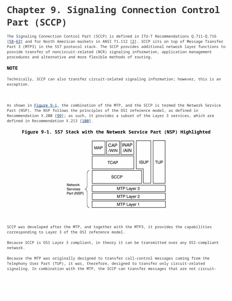
As shown in Figure 9-1, the combination of the MTP, and the SCCP is termed the Network Service Part (NSP). The NSP follows the principles of the OSI reference model, as defined in Recommendation X.200 [99]; as such, it provides a subset of the Layer 3 services, which are defined in Recommendation X.213 [100].
Figure 9-1. SS7 Stack with the Network Service Part (NSP) Highlighted
SCCP was developed after the MTP, and together with the MTP3, it provides the capabilities corresponding to Layer 3 of the OSI reference model.
Because SCCP is OSI Layer 3 compliant, in theory it can be transmitted over any OSI-compliant network.
Because the MTP was originally designed to transfer call-control messages coming from the Telephony User Part (TUP), it was, therefore, designed to transfer only circuit-related signaling. In combination with the MTP, the SCCP can transfer messages that are not circuit-related. These messages are used to support services such as toll-free calling, Local Number Portability (LNP) and Completion of Calls to Busy Subscribers (CCBS) in Intelligent Networks and mobility, roaming, and SMS in cellular networks.
SCCP provides the following additional capabilities over the MTP:
Enhances MTP to meet OSI Layer 3 Powerful and flexible routing mechanisms

Enhanced transfer capability, including segmentation/reassembly when message is too large to fit into one Message Signal Unit (MSU)
Connectionless and connection-oriented data transfer services
Management and addressing of subsystems (primarily database-driven applications)
SCCP is used extensively in cellular networks. Base Station Subsystem Mobile Application Part (BSSMAP) and Direct Transfer Application Part (DTAP) use it to transfer radio-related messages in Global System for Mobile communication (GSM). In conjunction with Transfer Capabilities Application Part (TCAP), SCCP is also used throughout the GSM Network Switching Subsystem (NSS) to transport Mobile Application Part (MAP) signaling between the core GSM components to enable subscriber mobility and text messaging (SMS), among other items. For example, when the Visitor Location Register (VLR) queries the Home Location Register (HLR) to obtain the subscriber's profile, SCCP is responsible for transferring both the query and the response back to the VLR. For more information about GSM, see Chapter 13, "GSM and ANSI-41 Mobile Application Part (MAP)."
Cellular intelligent network protocols, Wireless Intelligent Network (WIN), and Customizable Applications for Mobile Enhanced Logic (CAMEL) also use SCCP with TCAP (seeChapter 10, "Transaction Capabilities Application Part [TCAP]") to provide intelligent network functionality in a cellular environment. Figure 9-2 shows a typical cellular protocol stack, as found at a GSM-MSC.
Figure 9-2. Typical SS7 Stack Used in GSM Networks
Fixed-line networks primarily use SCCP for intelligent network applications and advanced supplementary services. Fixed-line intelligent networks use Advanced Intelligent Network (AIN) within North America and Intelligent Network Application Protocol (INAP) outside of North America (see Chapter 11, "Intelligent Networks [IN]"). AIN/INAP both use SCCP's transport, application management, and enhanced routing functionalities. Two example supplementary services that require the use of SCCP include CCBS and Completion of Calls on No Reply (CCNR).
This chapter looks at the functions of SCCP in some detail, beginning with an outline of the SCCP architecture and then moving onto protocol classes, connectionless and connection-oriented procedures, SCCP management functions, and most importantly, SCCP routing, including the use of global titles.
SCCP Architecture
As shown in Figure 9-3, SCCP is composed of the following four functional areas:
SCCP connection-oriented control (SCOC)— Responsible for setting up and releasing a virtual connection between two SCCP users. SCOC can offer features including sequencing, flow control, and

segmentation and can override congestion procedures by assigning data priority. The section, "SCCP Connection-Oriented Control (SCOC)" describes SCOC in more detail
SCCP connectionless control (SCLC)— Responsible for transferring data between SCCP users without creating a virtual connection. SCLC is described in the "SCCP Connectionless Control (SCLC)" Section. In addition to segmentation, it can perform limited sequencing.
SCCP routing control (SCRC)— Provides additional routing beyond that offered by MTP3, through the use of global titles. The "Global Title Routing" section fully explains global titles.
SCCP management (SCMG)— Responsible for tracking application status and informing SCMG at other SCCP nodes, as necessary. It is described later in this chapter in the section, "SCCP Management (SCMG)."
Figure 9-3. The SCCP Architecture
The term SCCP Users refers to the applications that use SCCP's services. These are primarily database-driven applications. Such applications use the services of TCAP described in Chapter 10 for peer application layer communication and the services of SCCP for managing the transport of messages between those applications.
Applications that use the services of SCCP are known as subsystems.
SCCP Message Transfer Services
The SCCP provides two categories of service for data transfer: connection-oriented services and connectionless services. Within each service category, two classes of service are defined as follows:
Class 0— Basic connectionless class Class 1— In-sequence delivery connectionless class
Class 2— Basic connection-oriented class
Class 3— Flow control connection-oriented class
Connection-oriented Versus Connectionless Services
The analogy of sending letters and postcards best explains the difference between the connection-oriented and the connectionless services. The postal service carries out the physical transfer and is therefore analogous to MTP. Connection-oriented service is much like the exchange of formal letters. When you send a formal letter, you might assign a reference to it—"Our Reference X." When the receiving party responds, they might also assign

their own reference to the letter and also copy the sender's reference—"Your Reference X." From that point on, both parties state their own and each other's assigned reference. SCCP connection-oriented service uses the same principles; the "Our Reference" is known as the Source Local Reference (SLR), and the "Your Reference" is known as the Destination Local Reference (DLR). This is similar in principle to Transmission Control Protocol (TCP): data is sent only when a virtual connection has been established through the initial exchange of identifiers. Figure 9-4 illustrates this principle.
Figure 9-4. Analogy of Connection-oriented Service with Official Mail Correspondence
Connectionless service is like sending postcards, where the sender and recipient do not establish references. In principle, it is similar to User Datagram Protocol (UDP): data is sent without first establishing a virtual connection using identifiers.
NOTE
SCCP transfers the data using the signaling network for transport. Trunks are not involved.
User Data and Segmentation
The data (from subsystems) is sent in information elements called Network Service Data Units (NSDUs). SCCP provides the capability to segment or reassemble an NSDU that is too large to fit in a single MTP message (MSU) so that it can be transmitted over a number of MSUs (16 maximum). When using the connectionless classes, if an NSDU is greater than 255 octets when using a UDT message or 254 when using a XUDT message, the originating node splits the NSDU into a number of XUDT messages. For a description of UDT and XUDT messages, see section "Message Types" and refer to Appendix C, "SCCP Messages (ANSI/ETSI/ITU-T)." If an NSDU is greater than 255 octets when using the connection-oriented classes, the originating node splits the NSDU into several DT messages. The receiving node reassembles the NSDU. For a description of the DT message, see the section on "Message Types" and refer to Appendix C. Theoretically, the maximum amount of user data is 3952[1] octets in ITU-T SCCP [58-61] and [2] 3904 octets in ANSI SCCP. This excludes optional parameters and global titles, which will appear to be repeated in each message. The ITU-T recommends using 2560 as the maximum NSDU size as a

safe implementation value [16] because it allows for the largest global title and numerous optional parameters. The section on "SCCP Routing Control (SCRC)" covers global titles.
[1] 3952 = (254 - 7) * 16, where 254 is the user data length fitting in one XUDT, 16 is the maximal number of segments and 7 is the length of the optional parameter: "segmentation" is followed by the end of the optional parameters octet [16].
The parameter Protocol Class within each SCCP message specifies the protocol class. Before giving a further explanation of connectionless and connection-orientated procedures the following sections discuss the four classes of data transfer that SCCP provides.
Connectionless Protocol Classes
Class 0 provides a basic connectionless service and has no sequencing control. It does not impose any conditions on the Signaling Link Selection (SLS) values that MTP3 inserts; therefore, SCCP messages can be delivered out of sequence. Class 0 can be considered a pure connectionless service. See Chapter 7, "Message Transfer Part 3 (MTP3)," for information about the SLS field.
Class 1 service adds sequence control to the Class 0 service by requiring the SCCP to insert the same SLS field for all NSDUs that have the same Sequence Control parameter. The higher layers indicate to SCCP whether or not a stream of NSDUs should be delivered in sequence. Therefore Class 1 is an enhanced connectionless service that provides basic in sequence delivery of NSDUs. Failures at the MTP level can still result in messages being delivered out of sequence.
TCAP is the typical user of SCCP connectionless services. The other user is Base Station Subsystem Application Part (BSSAP), which is used solely for GSM cellular radio related signaling. See Chapter 3, "The Role of SS7," for a brief description of BSSAP. Although the applications (subsystems) use TCAP directly, they are considered SCCP users because TCAP is considered transparent. See Chapter 10 for more information about TCAP.
NOTE
Common subsystems include Local Number Portability (LNP), Customizable Application Part (CAP), MAP, INAP, and AIN.
Table 9-1 shows the connectionless service protocol classes and features.
Table 9-1. Connectionless Service Protocol Classes
Protocol Class and Name Features Example Use
Protocol Class 0: Basic Connectionless
Independent message transport, no sequencing
Some BSSMAP messages (Paging), TCAP
Protocol Class 1: Connectionless Service
Independent message transport, limited sequencing
TCAP

Connection-oriented Protocol Classes
Class 2 provides a basic connection-oriented service by assigning local reference numbers to create a logical connection. Messages that belong to the same connection are assigned the same SLS value to ensure sequencing. Class 2 does not provide flow control, loss, or missequence detection.
Class 3 is an enhanced connection-oriented service that offers detection of both message loss and mis-sequencing (for each connection section). Class 3 also offers flow control using an expedited data transfer function. The ETSI European SCCP standard, ETS 300-009 [10], offers support for Class 3 only from V1.4.2 (November 1999) onwards.
The ITU-T had specified a Class 4, but this was never implemented on live networks and was later removed in White Book editions.
Table 9-2 shows the connection-oriented service protocol classes and features.
Table 9-2. Connection-oriented Service Protocol Classes
Protocol Class and Name Features Example Use
Protocol Class 2: Basic Connection-oriented Service
Logical signaling connection used for message transport Some BSSMAP messages (Setup)
Protocol Class 3: Connection-oriented Service
Logical signaling connection used for message transport, and flow control (expedited data transfer)
No known current use
SCCP Connectionless Control (SCLC)
SCLC is used to provide the capabilities that are necessary to transfer one NSDU in the "data" field of a UDT, Long Unit Data (LUDT), and XUDT message. For a description of SCCP messages, see section "Message Types" and Appendix C. The SCLC routes the message without regard to the route that the messages follow through the network. These services are provided without setting up a logical connection.
SCLC formats the user data into a message of the appropriate protocol class (0 or 1 in the case of connectionless) and transfers it to SCRC for routing. The section on "SCCP Routing Control (SCRC)" describes SCRC. On receiving a message, SCLC is responsible for decoding and distributing the message to the appropriate subsystem. Figure 9-5shows data transfer using SCLC: data is simply sent without the prior establishment of references at each side.
Figure 9-5. The Transfer of Connectionless Messages from One SCCP User to Another

SCCP Connection-Oriented Control (SCOC)
SCOC is used to route messages through a specific, fixed logical network path. To establish a dedicated logical connection between an originating SCCP user (subsystem) and a terminating SCCP user (subsystem), the SCCP users residing at different nodes throughout the network communicate with each other.
A signaling connection between the SCCP users is established, making both SCCP users aware of the transaction by using the DLR and SLR parameters. The signaling connection is released at the end of the transaction (information transfer). This is similar to SS7 protocol TUP/ISUP, which is used to control telephony calls, in that a connection is setup and released at a later time. However, the connection is virtual; there is not a trunk with user traffic being set up and released—rather, there is a virtual connection over the signaling network for the purpose of data transfer between applications (subsystems).
NOTE
SCCP connection-oriented services (Class 2 and Class 3) are virtual connections between users of the signaling system and bear no relation to connections between subscribers (trunks).
Connection-oriented procedures can be split into three phases:
Connection Establishment Phase— The SCCP users set up a logical, fixed path that the data packets will follow. The path might involve only two or three nodes with SCCP capability or, depending on how many intermediate nodes exist between the originator and terminator, it might involve a much larger number.
Data Transfer Phase— After the connection is established, the data that is to be transferred is converted into an NSDU and sent in a DT1 or DT2 message. For a description of SCCP messages, see the section on "Message Types" and Appendix C. Each NSDU is uniquely identified as belonging to a specific signaling connection. In this way, it is possible for the SCCP to simultaneously handle independent signaling connections.
Connection Release Phase— After all NSDUs have been transmitted and confirmed, either or both of the user applications that initiated the process release the logical path. A release can also occur if the connection fails.
An example of a connection-oriented data transfer is carried out in Figure 9-6. At the request of the SCCP user, SCCP A establishes a logical connection by sending a Connection Request (CR) message to SCCP B and assigning a SLR to the request. The remote node confirms the connection by sending a Connection Confirm (CC) message and includes its own SLR and a DLR that is equal to SCCP A's SLR. This gives both sides a reference for the connection.
Figure 9-6. The Transfer of Connection-oriented Messages from One SCCP User to Another Using a Temporary Connection

The CR message contains the address of the destination SCCP node and user. The subsequent data message DT1 only needs to send the DLR because the logical connection has been established through the proceeding exchange of SLR and DLR. The clear-down messages contain both SLR and DLR. If intermediate nodes are involved, they make associations between pairs of SLR/DLRs to establish the logical connection. Upon release, the SLR/DLR references are available for further use on other transactions. SCCP nodes can establish multiple simultaneous logical connections through the use of the SLR and DLR.
In Figure 9-5, if SCCP B received a CR message and either the SCCP B or the SCCP A could not establish the connection, a Connection Refused (CREF) message would have been returned.
Classes 2 and 3 (discussed previously) can either establish temporary connections (that is, on demand by SCCP user), as shown in Figure 9-5, or permanent signaling connections that are established by management action. Temporary connections are analogous to dialup connections, and permanent connections are analogous to leased lines. The connection establishment and release services are not required on permanent connections.
SCCP Messages and Parameters
A full list and descriptions of ITU-T and ANSI SCCP messages is provided in Appendix C. This section concentrates on the core messages and parameters. Table 9-3 shows the full list of SCCP messages in a chart that shows the protocol class(es) in which the messages operate. Both ANSI [2] and ITU-T [60] have identical SCCP message sets.
Table 9-3. The SCCP Message Types and Corresponding Protocol Class(es)
SCCP Message
Protocol Classes
0 1 2 3
CR (Connection Request)
X X
CC (Connection Confirm)
X X

Table 9-3. The SCCP Message Types and Corresponding Protocol Class(es)
SCCP Message
Protocol Classes
0 1 2 3
CREF (Connection Refused)
X X
RLSD (Released)
X X
RLC (Release Complete)
X X
DT1 (Data Form 1)
X
DT2 (Data Form 2)
X
AK (Data Acknowledgment)
X
UDT (Unitdata) X X
UDTS (Unitdata Service) X[1] X[1]
ED (Expedited Data)
X
EA (Expedited Data Acknowledgment)
X
RSR (Reset Request)
X
RSC (Reset Confirm)
X
ERR (Protocol Data Unit Error)
X X
IT (Inactivity Test)
X X
XUDT (Extended Unitdata) X X
XUDTS (Extended Unitdata Service) X[1] X[1]
LUDT (Long Unitdata) X X

Table 9-3. The SCCP Message Types and Corresponding Protocol Class(es)
SCCP Message
Protocol Classes
0 1 2 3
LUDTS (Long Unitdata Service) X[1] X[1]
[1] Type of protocol class is indeterminate (absence of protocol class parameter).
Message Structure
Figure 9-7 shows the format of an SCCP message.
Figure 9-7. The SCCP Message Structure
[View full size image]
Apart from the absence of a Circuit Identification Code field (CIC) field following the routing label, the basic message format is the same as an ISUP message (see Chapter 8, "ISDN User Part [ISUP]"). As with all other MTP users, SCCP messages are composed of three parts: a mandatory fixed part, mandatory variable part, and an optional part. All SCCP messages contain a mandatory fixed part, but not all of them have parameters to place in the mandatory variable or optional part. The following sections describe these three parts in more detail.
Mandatory Fixed Part (MF)

The mandatory fixed part consists of those parameters that must be present in the message and that are of a fixed length. Because the parameters are of a fixed length and are mandatory, no length indicator is required. In addition, because the parameter types and their order is known from the SCCP message type, no parameter names are required for stating the parameter types.
The mandatory fixed part contains pointers to the mandatory variable part and the optional part of the message. A pointer to the optional part is only included if the message type permits an optional part. If, on the other hand, the message type permits an optional part but no optional part is included for that particular message, then a pointer field that contains all zeros is used.
NOTE
A pointer is simply a single- or double-octet field that contains an offset, that is, a count from the beginning of the pointer to the first octet to which it points.
Mandatory Variable Part (MV)
The mandatory variable part consists of those parameters that must be present in the message and that are of a variable length. A pointer is used to indicate the start of each parameter. A length indicator precedes each parameter because the parameters are of a variable length. No parameter tags are required to state the parameter types because the parameter types and their order is explicitly defined by the SCCP message type. The parameters can occur in any order, but the associated pointers must occur in the same order as specified by the particular message type.
NOTE
The length indicator value excludes itself and the parameter name.
Optional Part (O)
The optional part consists of those parameters that are not always necessary. Each parameter is preceded by a parameter name and a length indicator. The parameter name is a unique one-octet field pattern that is used to indicate the parameter type. Because the parameter types and their order are unknown, it is required for each parameter type.
A one-octet End of Optional Parameters field is placed at the end of the last optional parameter. It is simply coded as all zeros.
Figure 9-8 illustrates an example message that contains all three parts. The message could contain no optional parameters, or even more optional parameters than in the example shown. Appendix L, "Tektronix Supporting Traffic," includes a trace that shows a CR message decode. The following section details the CR message.
Figure 9-8. An Example of a Connection Request (CR) Message Structure

Message Types
This section details example SCCP messages that are used in both connectionless and connection-oriented services. Appendix C presents a full list and description of ITU-T and ANSI SCCP messages.
Connection Request (CR)
Connection-oriented protocol Class 2 or 3 uses a CR message during the connection establishment phase. It is sent by an originating SCCP user to a destination SCCP user to set up a signaling connection (a virtual connection) between the two signaling points. As shown in Table 9-4, the various parameters that compose the message dictate the connection requirements. After receiving the CR message, SCCP initiates the virtual connection setup, if possible.
Table 9-4. CR Message Parameters
Parameter Type Length (octets)
Message type code MF 1

Table 9-4. CR Message Parameters
Parameter Type Length (octets)
Source local reference MF 3
Protocol class MF 1
Called party address MV 3 minimum
Credit O 3
Calling party address O 4 minimum
Data O 3–130
Hop counter O 3
Importance[1] O 3
End of optional parameters O 1
[1] This parameter is not present in ANSI SCCP
In GSM cellular networks, a CR message could be used between a Mobile Switching Center (MSC) and a Base Station Controller (BSC) to setup a signaling connection. Its data parameter could contain a BSSAP location update request or a BSSAP handover request, for example. A description of the GSM network entities MSC and BSC can be found inChapter 13, "GSM and ANSI-41 Mobile Application Part (MAP)."
Connection Confirm (CC)
Connection-oriented protocol Class 2 or 3 uses a CC message during the connection establishment phase. SCCP sends it at the destination node as an acknowledgement to the originating SCCP that it has set up the signaling connection. When the originating SCCP receives the CC message, it completes the setup of the signaling connection. Table 9-5shows the parameters that comprise a CC message.
Table 9-5. CC Message Parameters
Parameter Type Length (octets)
Message type code MF 1

Table 9-5. CC Message Parameters
Parameter Type Length (octets)
Destination local reference MF 3
Source local reference MF 3
Protocol class MF 1
Credit O 3
Called party address O 4 minimum
Data O 3–130
Importance[1] O 3
End of optional parameters O 1
[1] This parameter is not present in ANSI SCCP [2]
Connection Refused (CREF)
The connection-oriented protocol Class 2 or 3 can use a CREF message during the connection establishment phase. The destination SCCP or an intermediate node sends it to indicate to the originating SCCP that the signaling connection setup has been refused. As such, it is a negative response to a CR message. The refusal cause value is supplied to the originating SCCP. Table 9-6 shows the parameters of a CREF message.
Table 9-6. Connection Refused (CREF) Message Parameters
Parameter Type Length (octets)
Message type code MF 1
Destination local reference MF 3
Refusal cause MF 1

Table 9-6. Connection Refused (CREF) Message Parameters
Parameter Type Length (octets)
Called party address O 4 minimum
Data O 3–130
Importance[1] O 3
End of optional parameters O 1
[1] This parameter is not present in ANSI SCCP [2]
In GSM cellular networks, a CREF message can be sent from an MSC to a BSC (or vice versa) to refuse the requested signaling connection because the SCCP of the signaling point (MSC or BSC) cannot provide the connection.
Released (RLSD)
The connection-oriented protocol Class 2 or Class 3 uses a RLSD message during the release phase. It is sent in the forward or backward direction to indicate that the sending SCCP wants to release the signaling connection. Table 9-7 shows the parameters of a RLSD message.
Table 9-7. RLSD Message Parameters
Parameter Type Length (octets)
Message type code MF 1
Destination local reference MF 3
Source local reference MF 3
Release cause MF 1
Data O 3–130
Importance[1] O 3

Table 9-7. RLSD Message Parameters
Parameter Type Length (octets)
End of optional parameters O 1
[1] This parameter is not present in ANSI SCCP [2]
In GSM cellular networks, a RLSD message is always sent from the MSC to the BSC (or vice versa) to release the SCCP connection and the resources that are associated with it.
Release Complete (RLC)
The connection-oriented protocol Class 2 or 3 uses a RLC message during the release phase. It is sent in the forward or backward direction as a response to the RLSD message to indicate the receipt of the RLSD and the execution of the appropriate actions for releasing the connection. Table 9-8 shows the parameters of an RLC message.
Table 9-8. RLC Message Parameters
Parameter Type Length (octets)
Message type code MF 1
Destination local reference MF 3
Source local references MF 3
NOTE
Do not confuse a SSCP RLC message with an ISUP RLC message. The former has nothing to do with clearing voice circuits, while the latter does. They belong to different user parts and are distinguished as such by the Service Indicator Octet (SIO) described in Chapter 7.
Data Form 1 (DT1)
Only connection-oriented protocol Class 2 uses a DT1 message during the data transfer phase. Either end of a signaling connection sends it to transparently pass SCCP user data between two SCCP nodes. Table 9-9 shows the parameters of a DT1 message.
Table 9-9. DT1 Message Parameters
Parameter Type Length (octets)
Message type code MF 1
Destination local reference MF 3
Segmenting/reassembling MF 1
Data MV 2–256
DT1 messages are used in cellular networks to transfer data between the BSC and MSC after CR and CC messages have established the connection. All data transfer between BSC and MSC is performed using DT1 messages. DT2 messages (used for protocol Class 3) are not used in GSM (or DCS1800).
Unitdata (UDT)
A UDT message is used to send data in connectionless mode using connectionless protocol Class 0 and Class 1. Table 9-10 shows the parameters of a UDT message.
Table 9-10. Unitdata Message (UDT) Parameters
Parameter Type Length (octets)
Message type code MF 1
Protocol class MF 1
Called party address MV 3 minimum
Calling party address MV 2 minimum[1]
Data MV 2-X[2]
[1] ITU-T states a minimum length of 3, and a minimum length of 2 only in a special case. ANSI specifies a minimum length of 2.
[2] ITU-T states that the maximum length is for further study. ITU-T further notes that the transfer of up to 255 octets of user data is allowed when the SCCP called and calling party address do not include a global title. ANSI states that the maximum length is 252 octets.

UDT messages are commonly used for TCAP communication within IN services. In GSM cellular networks, UDT messages are used by the MAP protocol to send its messages. For a description of the MAP protocol see Chapter 13, "GSM and ANSI-41 Mobile Application Part (MAP)." SCCP management messages are transmitted using also the UDT message. SCCP management message are described in Section SCCP Management (SCMG) and in Appendices C, "SCCP Messages (ANSI/ETSI/ITU-T)."
Unitdata Service (UDTS)
A UDTS message is used in connectionless protocol Class 0 and 1. It indicates to the originating SCCP that a UDT message that is sent cannot be delivered to its destination. A UDTS message is only sent if the option field in the received UDT was set to return an error. Table 9-11 shows the parameters of a UDTS message.
NOTE
UDTS, LUDTS, and XUDTS indicate that the corresponding message (UDT, LUDT, and XUDT respectively) could not be delivered to the destination.
Table 9-11. UDTS Message Parameters
Parameter Type Length (octets)
Message type code MF 1
Return cause MF 1
Called party address MV 3 minimum
Calling party address MV 3 minimum
Data MV 2–X[1]
[1] ITU-T states that the maximum length is for further study. ITU-T further notes that the transfer of up to 255 octets of user data is allowed when the SCCP called and calling party address do not include a global title. ANSI states that the maximum length is 251 octets.
SCCP Routing Control (SCRC)
SCRC performs the following three functions:
Routes messages received from the MTP to appropriate local subsystem. Routes messages from local subsystems to other local subsystems.
Routes messages from local subsystems to subsystems in remote nodes by utilizing MTP's transport services. The destination is specified in the called party (CdPA) address parameter, which is supplied by the subsystem. The address can contain a combination of point code, system number, and global title.

SCCP addressing capabilities are flexible in contrast to those of MTP 3. As a result, the addressing capabilities are somewhat complex, thereby allowing several different combinations of routing parameters.
SCCP provides a routing function that allows signaling messages to be routed to a signaling point based on dialed digits, for example. This capability is known as Global Title Translation (GTT), which translates what is known as a global title (for example, dialed digits for a toll free number) into a signaling point code and a subsystem number so that it can be processed at the correct application. The section on "Global Title Translation" explains global titles and GTT.
The following are different types of network addressing that SCCP supports:
Point Code (PC) routing Subsystem Number (SSN) routing
Global Title (GT) routing
The MTP layer can only use point code routing, which is described in Chapter 7. Figure 9-9 shows a summary of MTP point code routing. Using MTP point code routing, MSUs pass through the STPs until they reach the SP that has the correct DPC. The following sections describe the SSN and GT routing.
Figure 9-9. Showing MTP Point Code Routing
[View full size image]
Subsystem Number (SSN) Routing
As previously mentioned, a subsystem is the name given to an application that uses SCCP; applications are predominantly database driven, except where ISUP is the subsystem (for a limited number of supplementary services), or where BSSAP uses SCCP (for radio-related signaling in GSM). As illustrated in Figure 9-10, a SSN is used to identify the SCCP user in much the same way as the service indicator identifies the MTP3 user (see Chapter 7).
Figure 9-10. An SSN and DPC Are Required for the Final Delivery of an SCCP Message

Figure 9-10 shows that a DPC and SSN are required in order to deliver a message to the correct application at the destination node.
It should be clear that noncircuit-related signaling (for example, database transactions to support IN/cellular, and so on) involve two distant applications (subsystems) exchanging information. The SSN is used to identify the application. Appendix L contains a trace that shows the decoding of a VLR calling an HLR (to perform a location update).
NOTE
Applications using TCAP rely on SCCP for message routing since TCAP itself has no routing capabilities. Therefore, each application is explicitly identified by an SSN at the SCCP level.
If SSN routing is used, the SSN is placed inside the CdPA parameter. The SCCP uses the SSN to send an SCCP message to a particular subsystem (application) at an SP. The SSN of the originating subsystem is also included in the Calling Party Address (CgPA) parameter to identify the subsystem that sent the SCCP message.
NOTE
SCCP's CgPA and CdPA parameters should not be confused with the Calling Party Number and Called Party Number parameters found in TUP/ISUP.
The SSN field is one octet in length and, therefore, has a capacity of 255 possible combinations.
Table 9-12 shows the SSN values that are specified by the ITU-T.

Table 9-12. ITU-T Specified Subsystem Numbers [60]
Bits
8 7 6 5 4 3 2 1 Subsystem
0 0 0 0 0 0 0 0 SSN not known/not used
0 0 0 0 0 0 0 1 SCCP management
0 0 0 0 0 0 1 0 Reserved for ITU-T allocation
0 0 0 0 0 0 1 1 ISUP (ISDN user part)
0 0 0 0 0 1 0 0 OMAP (Operation, Maintenance, and Administration Part)
0 0 0 0 0 1 0 1 MAP (Mobile Application Part)
0 0 0 0 0 1 1 0 HLR (Home Location Register)
0 0 0 0 0 1 1 1 VLR (Visitor Location Register)
0 0 0 0 1 0 0 0 MSC (Mobile Switching Centre)
0 0 0 0 1 0 0 1 EIC (Equipment Identifier Centre)
0 0 0 0 1 0 1 0 AUC (Authentication Centre)
0 0 0 0 1 0 1 1 ISUP supplementary services[1]
0 0 0 0 1 1 0 0 Reserved for international use
0 0 0 0 1 1 0 1 Broadband ISDN edge-to-edge applications
0 0 0 0 1 1 1 0 TC test responder[1]
0 0 0 0 1 1 1 1
to
0 0 0 1 1 1 1 1
Reserved for international use
0 0 1 0 0 0 0 0Reserved for national networks

Table 9-12. ITU-T Specified Subsystem Numbers [60]
Bits
8 7 6 5 4 3 2 1 Subsystem
to
1 1 1 1 1 1 1 0
1 1 1 1 1 1 1 1 Reserved for expansion of national and international SSN
[1] ANSI [2] simply states this field value as reserved.
ITU-T network specific subsystem numbers should be assigned in descending order, starting with 11111110 (for example, BSSAP is allocated 11111110 within GSM).
In GSM, subsystem numbers can be used between Public Land Mobile Networks (PLMNs), in which case they are taken from the globally standardized range (1–31) or the part of the national network range (129–150) that is reserved for GSM use between PLMNs, or within a PLMN, in which case they are taken from the part of the national network range (32–128 and 151–254) that is not reserved for GSM use between PLMNs.
Table 9-13 lists the globally standardized subsystem numbers that have been allocated by 3GPP for use by GSM/GPRS/UMTS cellular networks [106].
Table 9-13. 3GPP Specified Subsystem Numbers [60]
Bits Subsystem
0000 0110 HLR
0000 0111 VLR
0000 1000 MSC
0000 1001 EIR
0000 1010 AuC
1111 1010 BSC
1111 1011 MSC
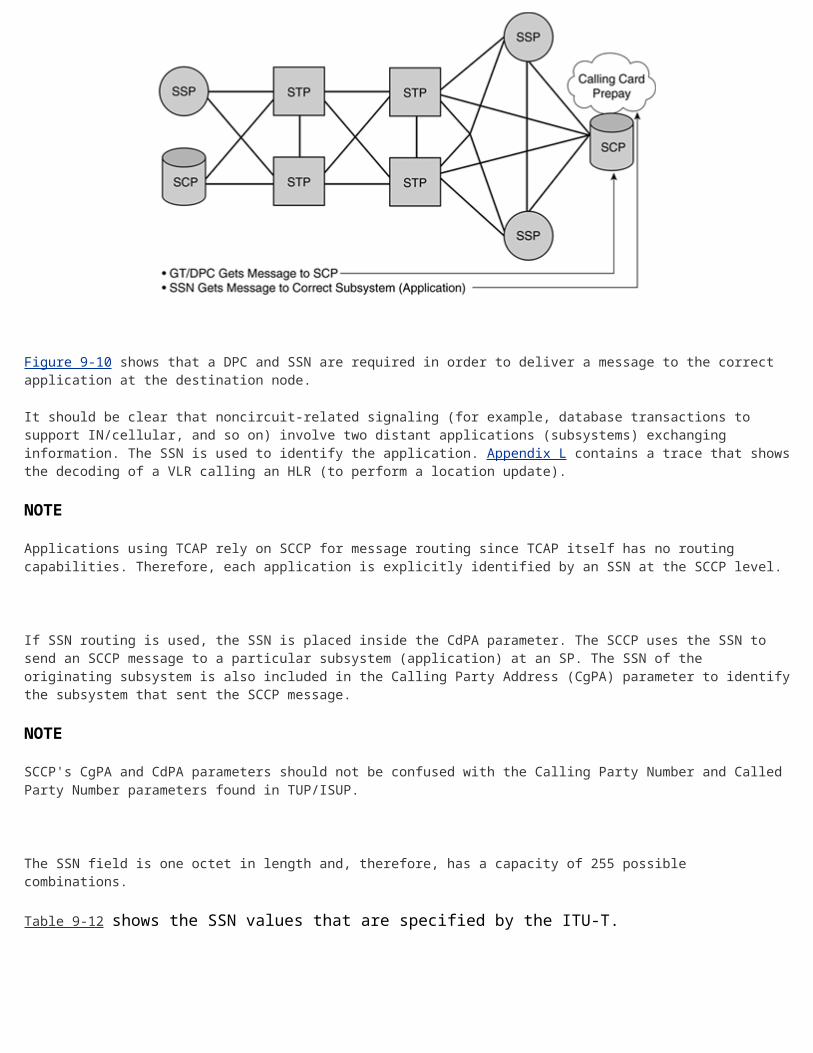
Table 9-13. 3GPP Specified Subsystem Numbers [60]
Bits Subsystem
1111 1100 SMLC
1111 1101 BSS O&M
1111 1110 BSSAP
1000 1110 RANAP
1000 1111 RNSAP
1001 0001 GMLC
1001 0010 CAP
1001 0011 gsmSCF
1001 0100 SIWF
1001 0101 SGSN
1001 0110 GGSN
Additionally INAP is specified as 0000 1111 [106].
Table 9-14 shows some common subsystems that are used within North America.
Table 9-14. Common North American Subsystem Numbers
Bits Subsystem
1111 1011 Custom Local Area Signaling Service (CLASS)
1111 1100 PVN (Private Virtual Network)

Table 9-14. Common North American Subsystem Numbers
Bits Subsystem
1111 1101 ACCS Automatic Calling Card Service (ACCS)
1111 1110 E800 (Enhanced 800)
Global Title Routing
"A global title is an address, such as dialed-digits, which does not explicitly contain information that would allow routing in the SS7 network."
Source: ITU-T-T Q.714 Subclause 2.1 [61]
There are many examples of digit strings that are global titles: in fixed-line networks, toll free, premium rate, numbers ported under LNP, or in the case of GSM cellular networks, the Mobile Subscriber ISDN Number (MSISDN) and International Mobile Subscriber Identity (IMSI) of the cellular subscriber and each HLR and VLR.
A GT is a telephony address. As such, the GT address must be translated into an SS7 network address (DPC+SSN) before it can be finally delivered. The GT is placed in the global title address information (GTAI) parameter within the CgPA and CdPA fields.
Global title routing is often used in fixed-line networks for calling-card validation and such services as telemarketing numbers (like a toll-free or premium rate). It is used in cellular networks for exchanging messages when an HLR and VLR belong to different networks or when several signaling points separate them.
Global Title Translation
GTT is an incremental indirect routing method that is used to free originating signaling points from the burden of having to know every potential application destination (that is, PC+SSN). This section describes the GTT process and the parameters associated with GTT.
For example, calling-card queries (which are used to verify that a call can be properly billed to a calling card) must be routed to an SCP that is designated by the company that issued the calling card. Rather than maintaining a nationwide database of where such queries should be routed (based on the calling-card number), SSPs generate queries that are addressed to their local STPs, which use GTT, to select the correct destination to which the message should be routed. STPs must maintain a database that enables them to determine where a query should be routed. GTT centralizes SCCP routing information at designated nodes, generally an STP, although SSP or SCP nodes are normally capable of performing GTT.
Even the SP that has been requested by another SP to perform GTT does not have to know the exact final destination of a message. Instead, it can perform intermediate GTT, in which it uses its tables to locate another SP that might have the final address required in its routing tables. An SP that performs a final GTT provides both the PC and SSN needed to route the message to its final destination. Intermediate GTT further minimizes the need for STPs to maintain extensive information about nodes that are far removed from them. GTT also is used at the STP to share a load among mated SCPs in both normal and failure scenarios. In these instances, when messages arrive at an SP for final GTT and routing to destination SP, the STP that routes the message can select from among available redundant SPs (for example, two mated SCPs). It can select an SP on either a priority basis or to equalize the load across the available SPs (this is referred to as loadsharing).

As an example, GTT is performed to determine the SCP location to which queries should be sent for number translation services such as tollfree and LNP. If you dial 1-800-BUY-MORE in the U.S. (toll-free begins with 0800 in many countries, including Great Britain), a query is sent to an SCP to translate the toll-free number to a routing number. SeeChapter 11 for a detailed explanation of how number translation services work.
When the SSP receives the tollfree or LNP number from the subscriber, it must determine the next hop destination to reach the SCP that provides the number translation service. In Figure 9-11, the SSP performs a GTT to determine that the next hop destination is the STP. The STP then performs the final GTT to route the message to the correct SCP. It is worth noting that when people in the SS7 field refer to "where the GTT is done", they are usually referring to the STP that provides the address of the final destination. In the previous example, GTT is actually done at the originating SSP in order to determine the next hop desination (the STP) towards the SCP and also at the STP to determine the final destination.
Figure 9-11. Example of GTT
[View full size image]
The SSP could always get the information from such a database (SCP) without using GTT if the DPC and SSN of the required toll free (or LNP) application were present in its routing tables. However, this would require maintaining a large number of routing entries at the SSP. New services (and applications) are frequently deployed into the SS7 network around the world. Some of the services might be proprietary and are, therefore, only accessible to the SSPs in the same proprietary network. Others are intended to be offered to other networks for a fee. If a service becomes universally available, it should not mean that every switch worldwide should be required to add the location (DPC) and application identifier (SSN) to its routing tables. Therefore, the GTT is used to centralize these routing functions.
SCCP routing (utilizing GTT) is an effective solution. The GTT information is placed at a limited number of network locations (such as STPs), and SSPs query these centralized locations without identifying from where the information is retrieved. When a switch requires a GT translation (that is, to address an application), it must only identify the nature of the translation it needs (for example, a toll-free number to E.164 "real" number), and send the request to a location that has GT routing tables to perform the translation. GTT is only performed on the number of digits required to identify where the SCCP message should be sent after translation. For example, in our toll-free illustration, GTT may only be performed on the three most significant digits (800) at the SSP to determine that all 800 numbers should be sent to a designated STP. At the STP, GTT could require translation of six digits (800-289) in order to determine the next STP for intermediate GTT or the final SCP destination. These decisions are made based on the administration of the network and agreements between network operators.

NOTE
It is important not to confuse directory number translation with GTT. When a query involving a number translation service is sent, GTT determines the SS7 address of the service (DPC + SSN) in order to deliver the message to the correct SP and subsystem. The service (such as toll-free) translates the number contained in the TCAP portion of the message, not the GT number in the SCCP portion of the message.
This allows a single entry in the SSP's routing table (such as the location of an STP) to provide 800 number translations. As stated previously in this section, with intermediate GTT, even the first location that receives the query (for DPC and/or SSN of destination application) does not have to maintain a routing table of all locations on the globe. Instead, it might have a table that indicates that all requests in several similar categories should be sent to one location, while requests in other categories can be sent somewhere else. These locations either directly identify the correct destination application (subsystem) or again, in the case of intermediate GTT, send it to another node for further GT routing analysis.
Figure 9-12 shows a further example using the GSM cellular network.
Figure 9-12. GTT on a GSM Cellular Network
[View full size image]
In Figure 9-12, a VLR in Country A originates a MAP Update Location message. The message contains the DPC of a Country A's International Switching Centre (ISC). The MSC/VLR contains the PC of the ISC that is provisioned in its routing tables. The message also contains the GT of the HLR (an E.164 number). The ISC at Country A changes the DPC to be an ISC of Country B. Again, this PC is already provisioned in its routing tables, and again, the GT of the HLR is present in the message. The ISC in Country B happens to have the data fill to translate the GT into a PC+SSN; therefore, it performs the GTT. Thus, the message is routed to the HLR via the GMSC using only the PC+SSN. GT translations are usually centralised at STPs to allow routing changes to be made easily.
Calling Party Address (CgPA) and Called Party Address (CdPA)
The CgPA contains information for identifying the originator of the SCCP message. The CdPA contains information to identify the SCCP message's intended destination. Figure 9-13 shows the placement of the CgPA/CdPA in the context of an MSU. Figure 9-14 shows the fields that are found within the CgPA/CdPA.
Figure 9-13. Positioning of the CgPA and CdPA Fields in the Context of an MSU
[View full size image]
Figure 9-14. The Subfields that Belong to Both the CgPA and CdPA Fields
Address Indicator (AI)
The AI is the first field within CgPA/CdPA and is one octet in length. Its function is to indicate which information elements are present so that the address can be interpreted—in other words, it indicates the type of addressing information that is to be found in the address field so the receiving node knows how to interpret that data.
The Routing Indicator (RI) specifies whether GTT is required; it determines whether routing based on PC+SSN or GT. If routing is based on the GT, the GT in the address is used for routing. If routing is based on PC+SSN, the PC and SSN in the CdPA are used. The PC from the CdPA is then placed into the MTP3 routing label DPC before MTP routing takes place.
The GT Indicator (GTI) specifies the GT format. In addition to those codes shown previously, 0101 to 0111 represent spare international use, and 1000 to 1110 represents spare national use.
The subsystem number is encoded "00000000" when the Subsystem Number is unknown (such as before GTT).
Figure 9-15 shows an example of SCCP routing using a GT.
Figure 9-15. Example Routing Parameters and Values

[View full size image]
There are four possible GT formats (bits C-F). '0100' is a common format that is used for international network applications, including INAP, which is discussed in Chapter 11, "Intelligent Networks (IN)," and MAP, which is discussed in Chapter 13, "GSM and ANSI-41 Mobile Application Part (MAP)." Figure 9-16 shows this common format.
Figure 9-16. GT Format 0100
[View full size image]
We now examine the fields with the format '0100' that are found within a GT.
Translation Type (TT)
The Translation Type (TT) field indicates the type of translation. When it is not used, the TT is coded 00000000. A GTI of 0010 is for national use only; the translation types for GTI 0010 is a national decision; it can imply the encoding scheme and the numbering plan. The ITU-T has not specified the translation types for GTI 0011. Figure 9-17 shows the TT values [60].

Figure 9-17. Translation Type Values [60]
[View full size image]
Encoding Scheme (ES)
The Encoding Scheme (ES) tells the receiving node how to translate the digits from binary code. Figure 9-18 shows the ES values [60].
Figure 9-18. Encoding Scheme Values [60]

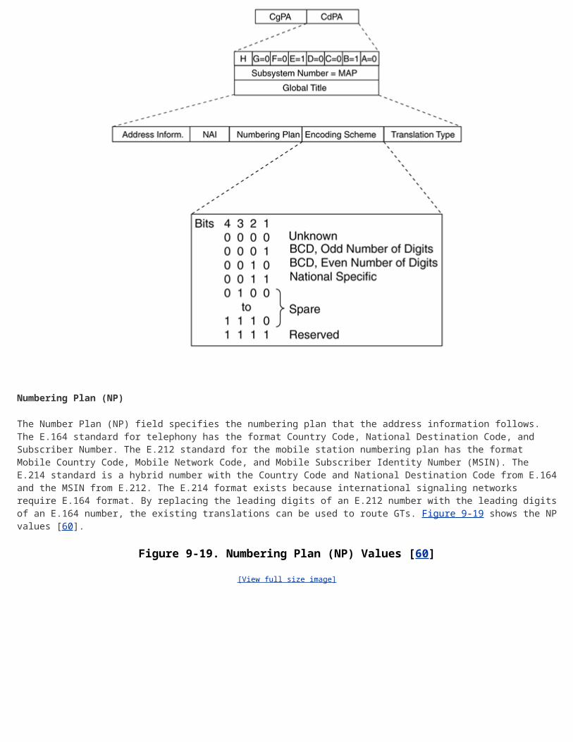
Numbering Plan (NP)
The Number Plan (NP) field specifies the numbering plan that the address information follows. The E.164 standard for telephony has the format Country Code, National Destination Code, and Subscriber Number. The E.212 standard for the mobile station numbering plan has the format Mobile Country Code, Mobile Network Code, and Mobile Subscriber Identity Number (MSIN). The E.214 standard is a hybrid number with the Country Code and National Destination Code from E.164 and the MSIN from E.212. The E.214 format exists because international signaling networks require E.164 format. By replacing the leading digits of an E.212 number with the leading digits of an E.164 number, the existing translations can be used to route GTs. Figure 9-19 shows the NP values [60].
Figure 9-19. Numbering Plan (NP) Values [60]
[View full size image]

Nature of Address Indicator (NAI)
The Nature of Address Indicator (NAI) field defines the address range for a specific numbering plan. The exact meaning depends on the numbering plan, not on GTI values.
Figure 9-20 shows the NAI values [60].
Figure 9-20. The Nature of Address (NAI) Values [60]
[View full size image]

Address Information (AI)
The AI contains the actual Global Title digits. These include enough of the most significant portion of the actual address digits to identify the destination node. For example, if a toll-free number of 800-123-4567 is dialed, the AI field might contain the digits 800 to identify an SCP to which the tollfree query should be sent. As shown in Figure 9-21, the address information is predominantly coded in Binary Coded Decimal (BCD) using four bits to code each digit.
Figure 9-21. BCD Encoding of Address Digits
[View full size image]

As an example of the parameters found for GT format "0100,"we consider SCCP addressing for GSM-MAP messages (which is discussed in Chapter 13, "GSM and ANSI-41 Mobile Application Part [MAP]). For Inter-PLMN addressing, the CdPA/CgPA contains the following values: SSN Indicator = 1 (SSN included); GT Indicator = 0100, GT includes Translation Type, Numbering Plan, Encoding Scheme and Nature of Address Indicator; TT = 00000000 (not used), and Routing Indicator = 0 (routing on GT).
SCCP Management (SCMG)
SCMG manages the status of subsystems and SCCP-capable signaling points (SPs). It maintains the status of remote SCCP SPs and that of local subsystems. It interacts with the SCRC to ensure that SCCP traffic is not sent to inaccessible destinations; if they are available, they use alternative routes or alternative subsystems to provide SCCP traffic rerouting. In addition, SCMG throttles SCCP traffic in the event of network congestion.
SCMG uses the concept of a "concerned" subsystem or SP. A "concerned" subsystem or SP is marked as requiring immediate notification if the affected subsystem or SP status changes. An affected SP might not have any subsystems or SPs marked as "concerned"; in this case, when a subsystem fails or inaccessibility occurs at the affected SP, it does not broadcast the status change. If it has entities marked as "concerned," it will broadcast the SSP message so the SCMG at the "concerned" entities can react to circumvent routing to the unavailable SP or subsystem.
A response method is used when a message is received that is addressed to an unavailable subsystem from an SP/subsystem that has not been notified of the status change. Upon receiving such a message, the affected SP returns the SSP message. The notified SP/subsystem can then periodically check whether the affected subsystem is available by sending a SCMG Subsystem status Test (SST) to the affected SP. The affected SP returns an SCMG Subsystem Allowed (SSA) message if the subsystem is available again. An SP/subsystem might not have been notified of the status change because it was not on the "concerned" list, the SSA/SSP message sent from the affected SP was lost, or the affected SP was recovering from either an MTP or SCCP failure, in which case it does not make a broadcast upon recovery. Figure 9-22 presents an example of the response method.
Figure 9-22. Possible Sequence of Messages Exchanged Between PC-Z and PC-Y When the Toll-Free Subsystem at PC-Z Becomes Unavailable
In Figure 9-22, the toll-free subsystem (SSN = 254) at SP-Z is down. When SP-Y tries to send connectionless data to the subsystem, SP-Z informs SP-Y that the subsystem is not available using the SSP message. SP-Y periodically checks whether the toll-free subsystem at SP-Z is back up again by using the SST message. On the second SST, the subsystem is available again and, as a result, SP-Z sends back a SSA message. It should be understood that other subsystems might exist at SP-Z and these might be functioning as normal, even though the toll free subsystem went down and later came back up again.
Upon receiving an SSP message, SP-Y updates its translation tables to select statically provisioned alternative routing to backup SPs and/or backup subsystems (if available).
Replicate Subsystems
Subsystems can be deployed in pairs; this is known as a replicate subsystem. Replicate subsystems are normally

only used at an SCP pair and are connected to a common intermediate node (STP). Under normal conditions, SCCP traffic can be load-shared across the replicate subsystems. Optionally, one of the subsystems can be designated as primary and the other as backup. If the primary subsystem becomes prohibited, the backup subsystem services the SCCP messages that were originally destined for the primary subsystem.
SCMG messages are used to coordinate the activity of a replicated subsystem. When one subsystem that belongs to the pair wishes to go out of service, a Subsystem Out-of-service Request (SOR) is sent to the replicate's other subsystem. If the subsystem that receives the SOR determines that the replicate can be taken out of service without degrading SCCP performance, a Subsystem Out-of-service Grant (SOG) is sent in response. The determination of whether the SOG is sent is based on the traffic load and available resources.
The ANSI SCCP standards specify three optional messages [2] for providing SCCP traffic mix information when subsystems are deployed as primary/backup pairs:
Subsystem Backup Routing (SBR) Subsystem Normal Routing (SNR)
Subsystem Routing Test (SRT)
If a primary subsystem becomes prohibited, the intermediate node that is connected to the replicate pair sends an SBR message to the backup subsystem to inform the backup subsystem that it is receiving traffic that was originally destined for the primary subsystem. The SRT is periodically sent to verify the status of a subsystem that is marked as backup routed. When the primary subsystem becomes available again, the SNR message is sent to update the traffic mix information at the backup node. This allows the backup node to be aware that it is no longer serving traffic that is rerouted from the primary node.
Figure 9-23 shows an example of using a replicated subsystem with a designated primary and backup node. When subsystem 254 is being removed from service, an SOR message is sent from SCP A to SCP B. SCP B determines that it is acceptable for the replicate subsystem to be removed from service and returns a SOG. In this example, the optional SBR message indicating that backup traffic is being received is sent from STP C to SCP B.
Figure 9-23. Replicate Subsystem Going Out of Service
In Figure 9-24, subsystem 254 is returned to service at SCP A, and the optional SNR message is sent to SCP B to indicate that it is no longer receiving backup traffic.
Figure 9-24. Replicate Subsystem Being Returned to Service

The messages used by SCMG are detailed in the following section.
SCMG Messages
SCMG messages are carried using the SCCP's connectionless service. When transferring SCMG messages, Class 0 is requested with no special option. The called and calling party address parameters that set the SSN to SCMG, and set the RI to route on SSN. SCMG messages are encapsulated in the data parameter of the UDT, XUDT, or LUDT message.
Table 9-15 shows the SCMG message types.
Table 9-15. The Format Identifiers of ANSI and ITU-T SCCP Management Messages.
Pseudonym/Message Binary Code
Subsystem Allowed (SSA) 00000001
Subsystem Prohibited (SSP) 00000010
Subsystem Status Test (SST) 00000011
Subsystem Out-of-service request (SOR) 00000100
Subsystem Out-of-service Grant (SOG) 00000101
SCCP/Subsystem Congested (SSC) 00000110
Subsystem Backup Routing[1] (SBR) 11111101
Subsystem Normal Routing[1] (SNR) 11111110
Subsystem Routing Test[1] (SRT) 11111111

[1] Found only in ANSI SCCP [2]
Appendix C includes a full description of these messages. It should be clear that these are independent from MTP3 signaling network management messages.
Signaling Point Status Management
Signaling point status management informs the other management functions of changes in other nodes. For point code failures, all functions that are associated with the failed node are marked as failed. Message routing programs broadcast messages to the rest of the network to inform the network of the failure.
Subsystem Status Management
Changes in the status of any of the local subsystems are reported to other SPs in the network. If the failure is at another node, this SCCP function informs the local subsystems about the problem.
The SCCP provides additional OSI network layer functionality and, with the MTP, provides an NSP. It uses the signaling network to transport noncircuit-related signaling, such as queries and responses between switches and telecommunications databases. SCCP provides two categories of service with two protocol classes in each. Classes 0 and 1 are within the connectionless category, and do not establish a virtual connection before transferring data. Classes 2 and 3 are within the connection-oriented category and establish a virtual (logical) connection before transferring data. SCCP provides flexible routing based on DPC, SSN, or GT, or a combination of all three. Global titles are an alias for a DPC and SSN and must be translated at nodes administered with the proper information (usually STPs). This process, which is known as GTT, frees originating nodes from having over-burdensome routing tables.
Related Documents