www.hiwin.tw Maintenance Manual SCARA Robot - RS406

Welcome message from author
This document is posted to help you gain knowledge. Please leave a comment to let me know what you think about it! Share it to your friends and learn new things together.
Transcript

www.hiwin.tw
Maintenance Manual
SCARA Robot - RS406
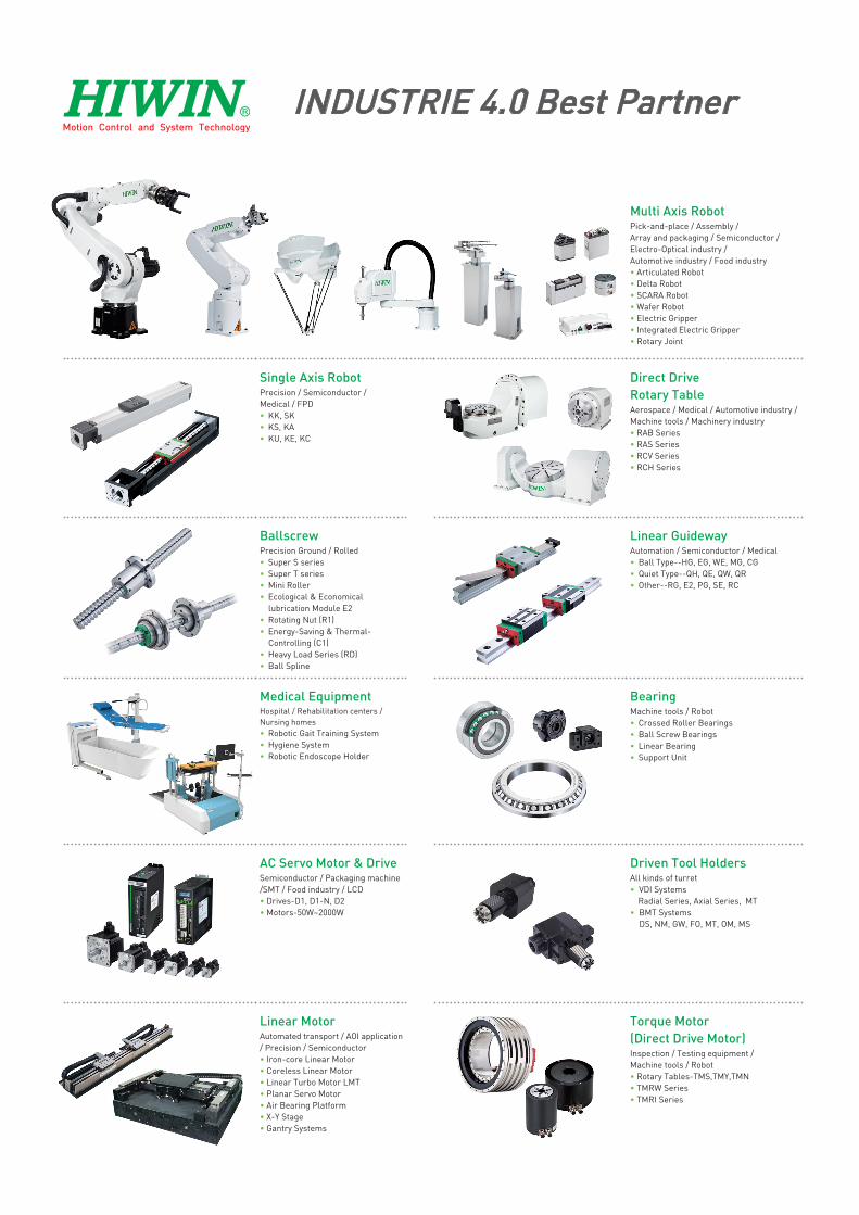
INDUSTRIE 4.0 Best Partner
Multi Axis RobotPick-and-place / Assembly / Array and packaging / Semiconductor / Electro-Optical industry / Automotive industry / Food industry• Articulated Robot• Delta Robot• SCARA Robot• Wafer Robot• Electric Gripper • Integrated Electric Gripper• Rotary Joint
Single Axis RobotPrecision / Semiconductor /Medical / FPD• KK, SK• KS, KA • KU, KE, KC
Direct Drive Rotary TableAerospace / Medical / Automotive industry / Machine tools / Machinery industry• RAB Series• RAS Series• RCV Series• RCH Series
BallscrewPrecision Ground / Rolled• Super S series• Super T series• Mini Roller• Ecological & Economical
lubrication Module E2• Rotating Nut (R1)• Energy-Saving & Thermal-
Controlling (C1)• Heavy Load Series (RD) • Ball Spline
Linear GuidewayAutomation / Semiconductor / Medical• Ball Type--HG, EG, WE, MG, CG• Quiet Type--QH, QE, QW, QR• Other--RG, E2, PG, SE, RC
Medical EquipmentHospital / Rehabilitation centers /Nursing homes• Robotic Gait Training System• Hygiene System• Robotic Endoscope Holder
BearingMachine tools / Robot• Crossed Roller Bearings • Ball Screw Bearings • Linear Bearing• Support Unit
AC Servo Motor & DriveSemiconductor / Packaging machine /SMT / Food industry / LCD• Drives-D1, D1-N, D2 • Motors-50W~2000W
Driven Tool HoldersAll kinds of turret • VDI Systems
Radial Series, Axial Series, MT • BMT Systems
DS, NM, GW, FO, MT, OM, MS
Linear MotorAutomated transport / AOI application / Precision / Semiconductor• Iron-core Linear Motor• Coreless Linear Motor • Linear Turbo Motor LMT • Planar Servo Motor • Air Bearing Platform• X-Y Stage • Gantry Systems
Torque Motor (Direct Drive Motor)Inspection / Testing equipment / Machine tools / Robot• Rotary Tables-TMS,TMY,TMN• TMRW Series• TMRI Series
C07UE301-1804
Company: HIWIN Technologies Corp.
Address: No.7, Jingke Rd., Taichung Precision Machinery Park, Taichung
City 40852, Taiwan
Date: July 2016
Version: 4.0
Tel: +886-4-23594510
Fax: +886-4-23594420
E-mail: [email protected]
Website: http://www.hiwin.tw
Copyright: The contents in this manual are used for the authorized customers and
suppliers. This manual should not be copied, reproduced, transmitted in any form or
distributed on Internet without HIWIN’s authorization.
All Rights Reserved
© HIWIN Technologies Corp. All rights reserved
C07UE301-1804
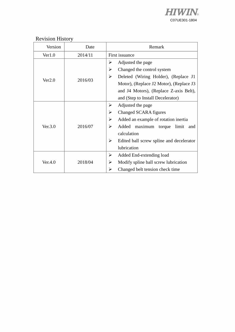
Revision History
Version Date Remark
Ver1.0 2014/11 First issuance
Ver2.0 2016/03
Adjusted the page
Changed the control system
Deleted (Wiring Holder), (Replace J1
Motor), (Replace J2 Motor), (Replace J3
and J4 Motors), (Replace Z-axis Belt),
and (Step to Install Decelerator)
Ver.3.0 2016/07
Adjusted the page
Changed SCARA figures
Added an example of rotation inertia
Added maximum torque limit and
calculation
Edited ball screw spline and decelerator
lubrication
Ver.4.0 2018/04
Added End-extending load
Modify spline ball screw lubrication
Changed belt tension check time
I
C07UE301-1804
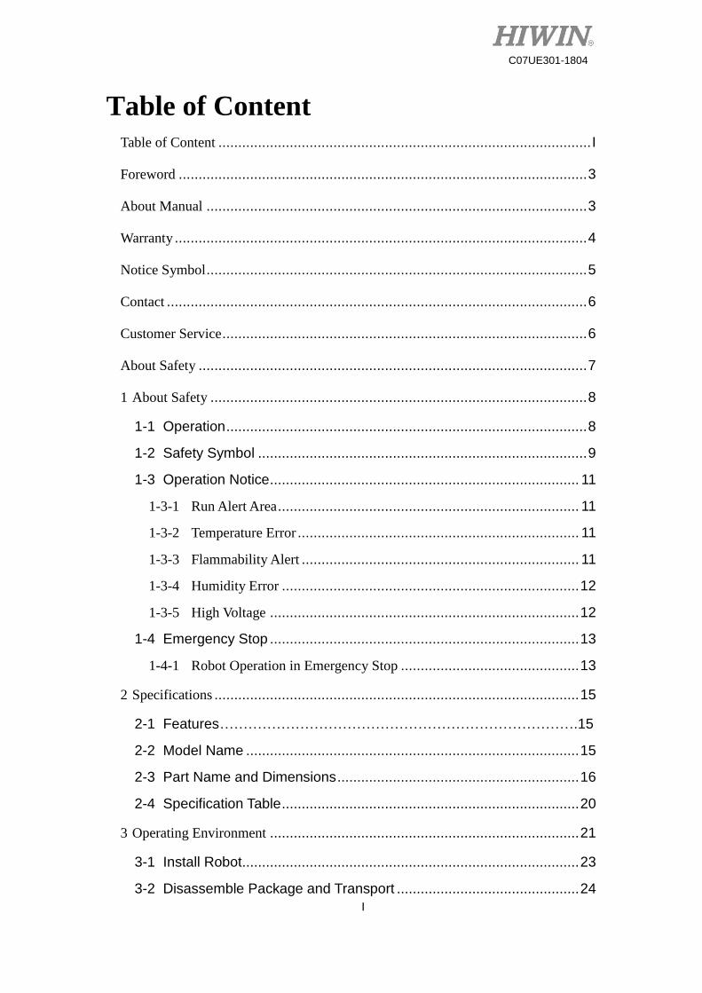
Table of Content
Table of Content .............................................................................................. I
Foreword ....................................................................................................... 3
About Manual ................................................................................................ 3
Warranty ........................................................................................................ 4
Notice Symbol ................................................................................................ 5
Contact .......................................................................................................... 6
Customer Service ............................................................................................ 6
About Safety .................................................................................................. 7
1 About Safety ............................................................................................... 8
1-1 Operation ........................................................................................... 8
1-2 Safety Symbol ................................................................................... 9
1-3 Operation Notice .............................................................................. 11
1-3-1 Run Alert Area ............................................................................ 11
1-3-2 Temperature Error ....................................................................... 11
1-3-3 Flammability Alert ...................................................................... 11
1-3-4 Humidity Error ........................................................................... 12
1-3-5 High Voltage .............................................................................. 12
1-4 Emergency Stop .............................................................................. 13
1-4-1 Robot Operation in Emergency Stop ............................................. 13
2 Specifications ............................................................................................ 15
2-1 Features ………………………………………………………………….15
2-2 Model Name .................................................................................... 15
2-3 Part Name and Dimensions ............................................................. 16
2-4 Specification Table ........................................................................... 20
3 Operating Environment .............................................................................. 21
3-1 Install Robot ..................................................................................... 23
3-2 Disassemble Package and Transport .............................................. 24
II
C07UE301-1804
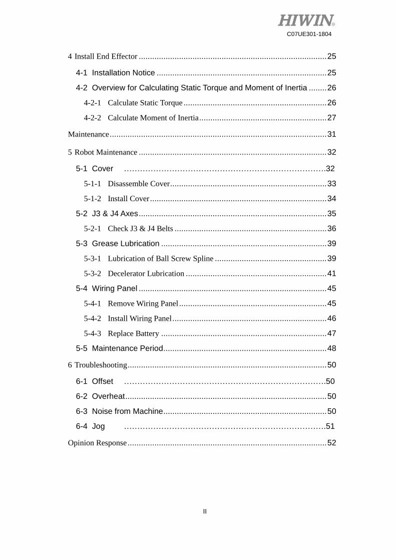
4 Install End Effector .................................................................................... 25
4-1 Installation Notice ............................................................................ 25
4-2 Overview for Calculating Static Torque and Moment of Inertia ........ 26
4-2-1 Calculate Static Torque ................................................................ 26
4-2-2 Calculate Moment of Inertia ......................................................... 27
Maintenance ................................................................................................. 31
5 Robot Maintenance .................................................................................... 32
5-1 Cover ………………………………………………………………….32
5-1-1 Disassemble Cover ...................................................................... 33
5-1-2 Install Cover ............................................................................... 34
5-2 J3 & J4 Axes .................................................................................... 35
5-2-1 Check J3 & J4 Belts .................................................................... 36
5-3 Grease Lubrication .......................................................................... 39
5-3-1 Lubrication of Ball Screw Spline .................................................. 39
5-3-2 Decelerator Lubrication ............................................................... 41
5-4 Wiring Panel .................................................................................... 45
5-4-1 Remove Wiring Panel .................................................................. 45
5-4-2 Install Wiring Panel ..................................................................... 46
5-4-3 Replace Battery .......................................................................... 47
5-5 Maintenance Period ......................................................................... 48
6 Troubleshooting ......................................................................................... 50
6-1 Offset ………………………………………………………………….50
6-2 Overheat .......................................................................................... 50
6-3 Noise from Machine ......................................................................... 50
6-4 Jog ………………………………………………………………….51
Opinion Response ......................................................................................... 52
3
C07UE301-1804
Foreword Thank you for purchasing the Selective Compliance Assembly Robot Arm or
Selective Compliance Articulated Robot Arm (SCARA). This manual will provide the
method for installing and maintaining the machine, and protect a user life from
improper operation. A user should carefully read the description prior to the operation.
If the regulations are not followed to cause the machine damage or injury, a user must
take the related responsibilities. After you read this manual, please keep it well so that
can be read any time.
About Manual This manual describes the SCARA Robot developed by HIWIN, whose structure
includes the body, the control panel, the Teaching Pendant (optional), the connection
cable and the software. A user who purchases the robot can operate and maintain the
robot via this manual.
This manual is suitable for the SCARA Robot only, which can be operated under
the ambient environment, but is not suitable for the related equipment and the operating
environment not mentioned in this manual, such as vacuum condition and equipment
involved in personal life.
4
C07UE301-1804
Warranty The SCARA Robot is strictly tested and examined, and delivered to a customer
after its performance meets our requirements.
Warranty Period:
The product provides one-year warranty period from the day since it is delivered.
For the detailed terms and clauses of maintenance and repair, please contact the agent.
Warranty Content:
Guarantee the equipment delivered to customer.
In the warranty period, we provide free maintenance for failure during the normal
operation. The failure after the warranty period is expired will be charged.
Disclaimer:
Even in the warranty period above-mentioned, the service will be charged when the
following items are met.
Failure and damage caused by incorrect operation different from the manual.
Reconstruct or remove the robot by yourself.
Failure and damage caused by improper adjustment/maintenance.
Failure and damage caused by act of nature disasters/fire/other factors.
If you operate the robot in the conditions or specifications beyond the manual,
we will not guarantee the basic performances.
We should not take any responsibility for human body (death or serious
injury)/damage incident/failure caused by not following “WARNINNG” and
“CAUTION” in this manual.
We can’t completely forecast all conditions for danger and failure. Such
ability to forecast shows the limit. Therefore, “WARNINNG”, “CAUTION” and
other items in this manual belong to the forecasting scopes.
5
C07UE301-1804
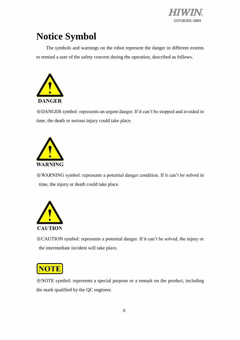
Notice Symbol The symbols and warnings on the robot represent the danger in different extents
to remind a user of the safety concern during the operation, described as follows.
※DANGER symbol: represents an urgent danger. If it can’t be stopped and avoided in
time, the death or serious injury could take place.
※WARNING symbol: represents a potential danger condition. If it can’t be solved in
time, the injury or death could take place.
※CAUTION symbol: represents a potential danger. If it can’t be solved, the injury or
the intermediate incident will take place.
※NOTE symbol: represents a special purpose or a remark on the product, including
the mark qualified by the QC engineer.
6
C07UE301-1804
Contact For the maintenance/examination/adjustment on the SCARA Robot, please contact
customer service.
Please prepare the following information when you contact us:
System name/series number
Software name/version
Problem on the system
Customer Service Customer hotline: +866-4-23594510
E-mail: [email protected]

7
C07UE301-1804
About Safety
8
C07UE301-1804
1 About Safety This chapter mainly describes the operation regulations about the SCARA Robot,
which not only provide the detailed operation information for a user and explain the
meaning for each alert symbol one by one, but also inform a user of the risk and the
emergency response during the operation.
1-1 Operation
For the sake of human body, the following regulations must be obeyed:
The robot can be operated or maintained by the trained and qualified
operators.
Please carefully read the description in this manual, so that can efficiently
and safely operate the robot.
The operators must be familiar with the position, the function and operation
for safety switches.
Please ensure there are no obstacles stacked around the robot prior to the
operation.
Don’t open or remove the shelter on the robot.
Please ensure the circuit systems have been indeed grounded prior to the
operation.
Before you replace any circuit, all power must be disconnected to avoid
electric shock.
Please immediately disconnect the main switch during the power failure or
disconnection.
Don’t stain, scratch or move the warning label and product nameplate.
9
C07UE301-1804
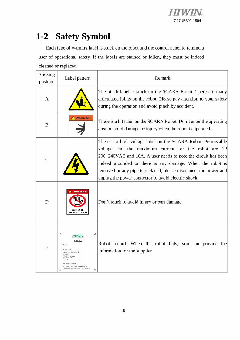
1-2 Safety Symbol
Each type of warning label is stuck on the robot and the control panel to remind a
user of operational safety. If the labels are stained or fallen, they must be indeed
cleaned or replaced.
Sticking
position Label pattern Remark
A
The pinch label is stuck on the SCARA Robot. There are many
articulated joints on the robot. Please pay attention to your safety
during the operation and avoid pinch by accident.
B
There is a hit label on the SCARA Robot. Don’t enter the operating
area to avoid damage or injury when the robot is operated.
C
There is a high voltage label on the SCARA Robot. Permissible
voltage and the maximum current for the robot are 1P
200~240VAC and 10A. A user needs to note the circuit has been
indeed grounded or there is any damage. When the robot is
removed or any pipe is replaced, please disconnect the power and
unplug the power connector to avoid electric shock.
D
Don’t touch to avoid injury or part damage.
E
Robot record. When the robot fails, you can provide the
information for the supplier.
10
C07UE301-1804
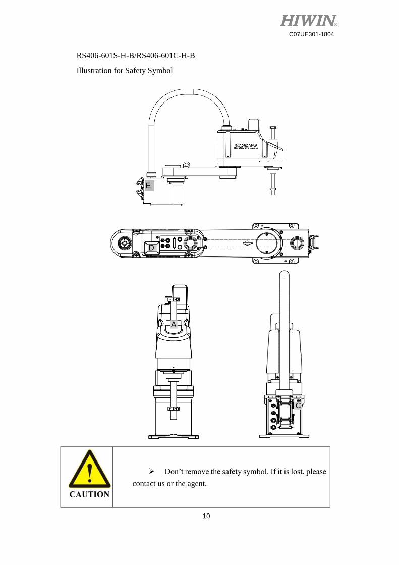
RS406-601S-H-B/RS406-601C-H-B
Illustration for Safety Symbol
Don’t remove the safety symbol. If it is lost, please
contact us or the agent.
E
A
C
D
11
C07UE301-1804
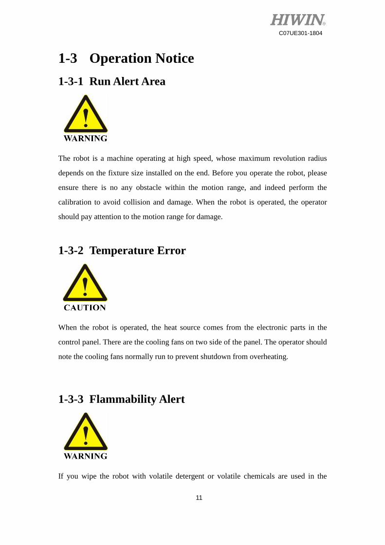
1-3 Operation Notice
1-3-1 Run Alert Area
The robot is a machine operating at high speed, whose maximum revolution radius
depends on the fixture size installed on the end. Before you operate the robot, please
ensure there is no any obstacle within the motion range, and indeed perform the
calibration to avoid collision and damage. When the robot is operated, the operator
should pay attention to the motion range for damage.
1-3-2 Temperature Error
When the robot is operated, the heat source comes from the electronic parts in the
control panel. There are the cooling fans on two side of the panel. The operator should
note the cooling fans normally run to prevent shutdown from overheating.
1-3-3 Flammability Alert
If you wipe the robot with volatile detergent or volatile chemicals are used in the
12
C07UE301-1804
process, please ensure the temperature and the fan condition at any time to avoid a fire.
1-3-4 Humidity Error
Electronic components in the robot and the control panel are made of metal materials,
which are more sensitive to the relative humidity of the operating environment. Higher
humidity will accelerate to oxidize the contacts of metal part and electronic component,
and loosen the assembly structure and cause poor contact; lower humidity will easily
generate static electricity and damage electronic components. It is recommended the
relative humidity in the ambient environment should be less than 50%.
1-3-5 High Voltage
1P 200~240VAC is supplied to the robot. Once electric leakage or touch by accident
takes place, it will cause serious injury or death. When you install the robot, you need
to check each connector is indeed connected, and ensure all circuits are not excessively
bent, even broken or damaged.
13
C07UE301-1804
1-4 Emergency Stop
If you feel the robot failed during the operation, please immediately press the
EMERGENCY STOP button. When you press the EMERGENCY STOP button, the
arm will stop in the shortest distance by the controller and the motor brake.
Don’t press the EMERGENCY STOP button when the arm normally operates. If
you press EMERGENCY STOP button during the operation, it could hit the peripherals
and internal hardware to cause damage.
The EMERGENCY STOP button is pressed in the urgent condition, not for
pause/run. If you want to stop the robot in the normal operation and the working path,
please operate it according to the software manual.
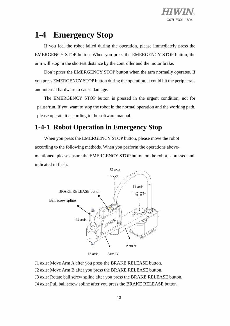
1-4-1 Robot Operation in Emergency Stop
When you press the EMERGENCY STOP button, please move the robot
according to the following methods. When you perform the operations above-
mentioned, please ensure the EMERGENCY STOP button on the robot is pressed and
indicated in flash.
J1 axis: Move Arm A after you press the BRAKE RELEASE button.
J2 axis: Move Arm B after you press the BRAKE RELEASE button.
J3 axis: Rotate ball screw spline after you press the BRAKE RELEASE button.
J4 axis: Pull ball screw spline after you press the BRAKE RELEASE button.
Ball screw spline
BRAKE RELEASE button
J4 axis
Arm B
J2 axis
J1 axis
J3 axis
Arm A
14
C07UE301-1804
Don’t apply excessive force to move the robot or
quickly rotate the parts after you press the EMERGENCY
STOP button. This condition could damage the robot.
Press the BRAKE RELEASE button after you press
the EMERGENCY STOP button to simultaneously release
the brake for four axes. Note that the object loaded on the
end could drop and cause injury or death owing to its
weight.
15
C07UE301-1804
2 Specifications
2-1 Features
The SCARA Robot, suitable for the ambient environment, can be applied for
delivering and assembling the components, such as electronic parts. The maximum
permissible inertia can reach 0.12 kg-m2.
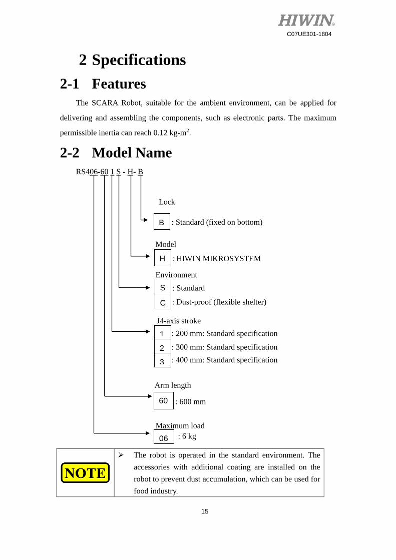
2-2 Model Name
RS406-60 1 S - H- B
The robot is operated in the standard environment. The
accessories with additional coating are installed on the
robot to prevent dust accumulation, which can be used for
food industry.
Model
: HIWIN MIKROSYSTEM
Environment
S
C
: Standard
: Dust-proof (flexible shelter)
J4-axis stroke
1
2
3
: 200 mm: Standard specification
: 300 mm: Standard specification
: 400 mm: Standard specification
Arm length
: 600 mm
06
Maximum load
: 6 kg
H
B : Standard (fixed on bottom)
Lock
60
16
C07UE301-1804
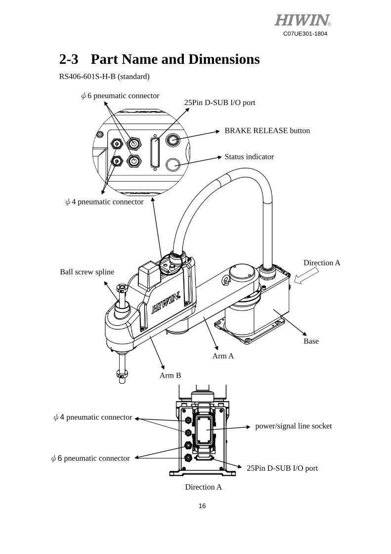
2-3 Part Name and Dimensions RS406-601S-H-B (standard)
Direction A
Base
Arm A
Arm B
Ball screw spline
BRAKE RELEASE button
Status indicator
25Pin D-SUB I/O port ψ6 pneumatic connector
ψ4 pneumatic connector
ψ6 pneumatic connector
ψ4 pneumatic connector
25Pin D-SUB I/O port
power/signal line socket
Direction A
17
C07UE301-1804
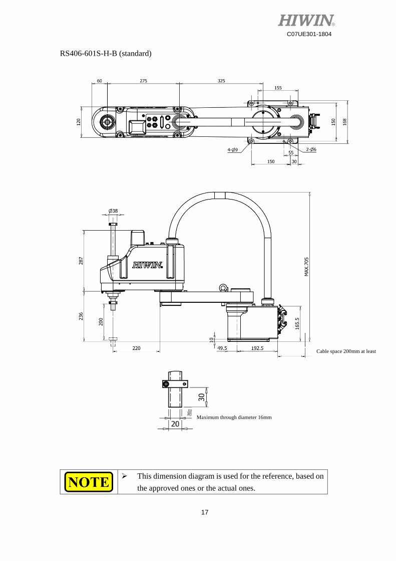
RS406-601S-H-B (standard)
This dimension diagram is used for the reference, based on
the approved ones or the actual ones.
Cable space 200mm at least
Maximum through diameter 16mm
18
C07UE301-1804
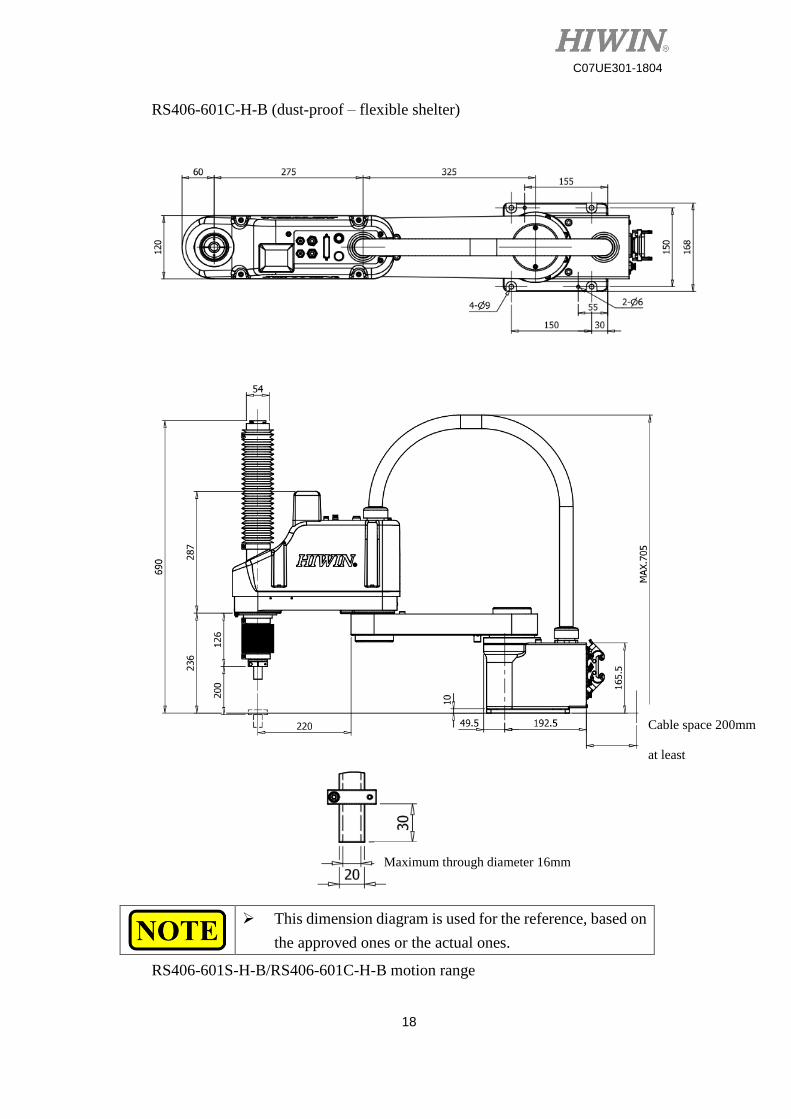
RS406-601C-H-B (dust-proof – flexible shelter)
RS406-601S-H-B/RS406-601C-H-B motion range
This dimension diagram is used for the reference, based on
the approved ones or the actual ones.
Cable space 200mm
at least
Maximum through diameter 16mm
19
C07UE301-1804
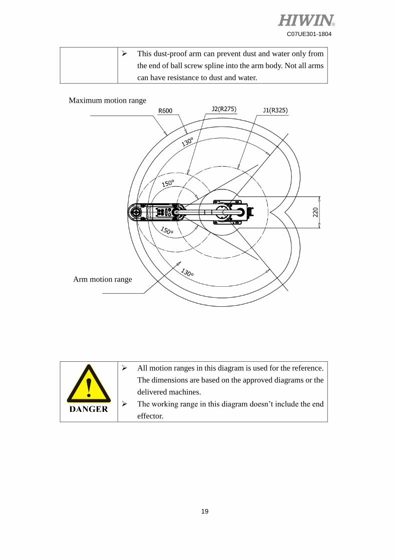
This dust-proof arm can prevent dust and water only from
the end of ball screw spline into the arm body. Not all arms
can have resistance to dust and water.
All motion ranges in this diagram is used for the reference.
The dimensions are based on the approved diagrams or the
delivered machines.
The working range in this diagram doesn’t include the end
effector.
Maximum motion range
(R660)
Arm motion range
20
C07UE301-1804
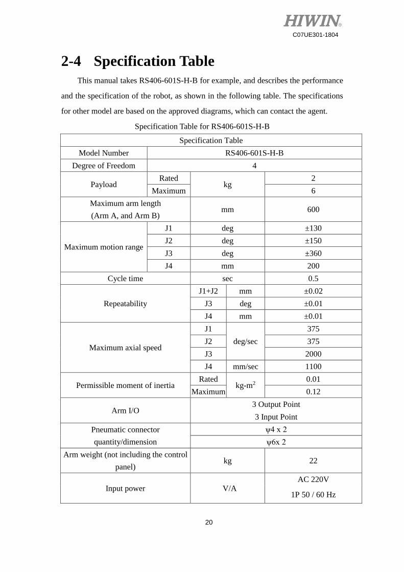
2-4 Specification Table
This manual takes RS406-601S-H-B for example, and describes the performance
and the specification of the robot, as shown in the following table. The specifications
for other model are based on the approved diagrams, which can contact the agent.
Specification Table for RS406-601S-H-B
Specification Table
Model Number RS406-601S-H-B
Degree of Freedom 4
Payload Rated
kg 2
Maximum 6
Maximum arm length
(Arm A, and Arm B) mm 600
Maximum motion range
J1 deg ±130
J2 deg ±150
J3 deg ±360
J4 mm 200
Cycle time sec 0.5
Repeatability
J1+J2 mm ±0.02
J3 deg ±0.01
J4 mm ±0.01
Maximum axial speed
J1
deg/sec
375
J2 375
J3 2000
J4 mm/sec 1100
Permissible moment of inertia Rated
kg-m2 0.01
Maximum 0.12
Arm I/O 3 Output Point
3 Input Point
Pneumatic connector
quantity/dimension
ψ4 x 2
ψ6x 2
Arm weight (not including the control
panel) kg 22
Input power V/A AC 220V
1P 50 / 60 Hz
21
C07UE301-1804
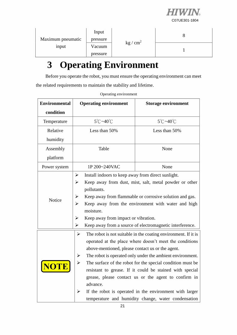
Maximum pneumatic
input
Input
pressure kg / cm2
8
Vacuum
pressure 1
3 Operating Environment Before you operate the robot, you must ensure the operating environment can meet
the related requirements to maintain the stability and lifetime.
Operating environment
Environmental
condition
Operating environment Storage environment
Temperature 5℃~40℃ 5℃~40℃
Relative
humidity
Less than 50% Less than 50%
Assembly
platform
Table None
Power system 1P 200~240VAC None
Notice
Install indoors to keep away from direct sunlight.
Keep away from dust, mist, salt, metal powder or other
pollutants.
Keep away from flammable or corrosive solution and gas.
Keep away from the environment with water and high
moisture.
Keep away from impact or vibration.
Keep away from a source of electromagnetic interference.
The robot is not suitable in the coating environment. If it is
operated at the place where doesn’t meet the conditions
above-mentioned, please contact us or the agent.
The robot is operated only under the ambient environment.
The surface of the robot for the special condition must be
resistant to grease. If it could be stained with special
grease, please contact us or the agent to confirm in
advance.
If the robot is operated in the environment with larger
temperature and humidity change, water condensation
22
C07UE301-1804
could take place inside. When it is used to move food,
please contact us or the agent to ensure it will not pollute
food.
The robot can’t be operated in the acid or corrosive
environment. In addition, the body could be corroded in the
salty environment.
23
C07UE301-1804
3-1 Install Robot
When you install the robot, please lock with M8 bolts. The bolt specifications need
to meet ISO898-1:10.9 or 12.9. The base is installed on the lock surface. It is
recommended the thickness be 20mm or more, and be made of the steel material to
reduce the operating vibration. It is suggested the surface roughness be 25µm or less
than 25µm. The other assemblies are installed with appropriate tools in accordance with
the operating manual to avoid injury or damage by the improper operation.
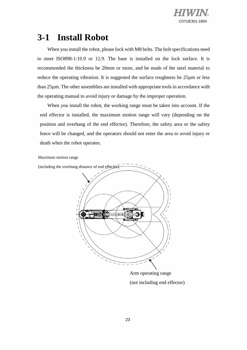
When you install the robot, the working range must be taken into account. If the
end effector is installed, the maximum motion range will vary (depending on the
position and overhang of the end effector). Therefore, the safety area or the safety
fence will be changed, and the operators should not enter the area to avoid injury or
death when the robot operates.
Maximum motion range
(including the overhang distance of end effector)
Arm operating range
(not including end effector)
24
C07UE301-1804
When you install the robot, please consider the
motion range (including the distance of end effector), and
set up the warning or safety fence.
The operators should not enter the area to avoid injury
or death when the robot operates.
3-2 Disassemble Package and Transport
The robot must be installed by the authorized engineer, and complied with the
national regulations. After you remove the package and take out the robot with a
protective bag, please transport it to the installation position by appropriate facilities.
The robot must be properly fixed during the transportation. The operator must note
the personal safety to prevent pinch or hurt from strong vibration or object.
The authorized staff can operate crane or forklift only.
When those without authorization perform the operations
above-mentioned, the surrounding operators could be
injured or the robot could be damaged.
Transport the robot with a cart.
The robot must be delivered by two operators or more
when transported with bard hands. The base, Arm A or
Arm B are held with two hands. Don’t pull black flexible
conduit or any connector.
When you adjust the position to install the robot,
please hold it with two hands so that it drops to pinch the
operator.
The robot must be indeed fixed on the transportation
facility to avoid collision, falling and damage when
transported in long distance.
25
C07UE301-1804
4 Install End Effector
4-1 Installation Notice
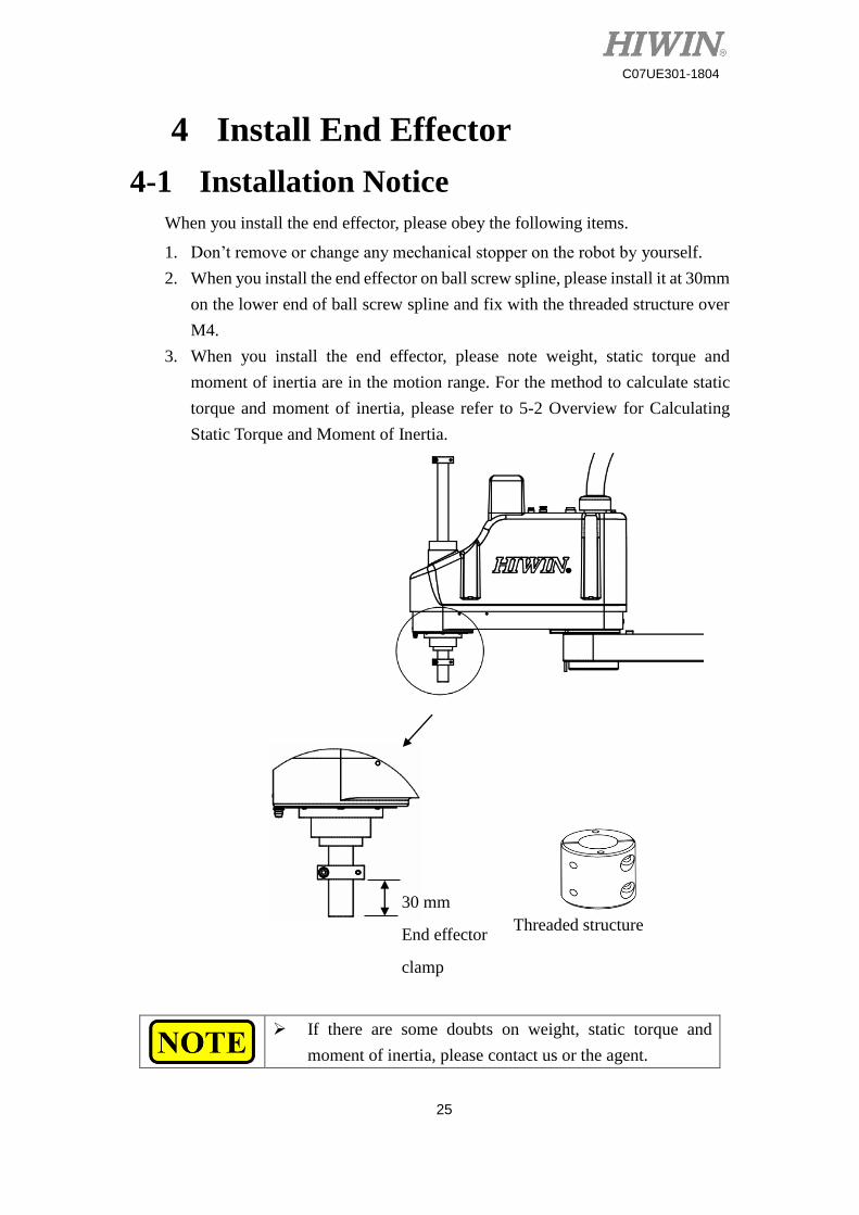
When you install the end effector, please obey the following items.
1. Don’t remove or change any mechanical stopper on the robot by yourself.
2. When you install the end effector on ball screw spline, please install it at 30mm
on the lower end of ball screw spline and fix with the threaded structure over
M4.
3. When you install the end effector, please note weight, static torque and
moment of inertia are in the motion range. For the method to calculate static
torque and moment of inertia, please refer to 5-2 Overview for Calculating
Static Torque and Moment of Inertia.
If there are some doubts on weight, static torque and
moment of inertia, please contact us or the agent.
30 mm
End effector
clamp
Threaded structure
26
C07UE301-1804
4-2 Overview for Calculating Static
Torque and Moment of Inertia
4-2-1 Calculate Static Torque
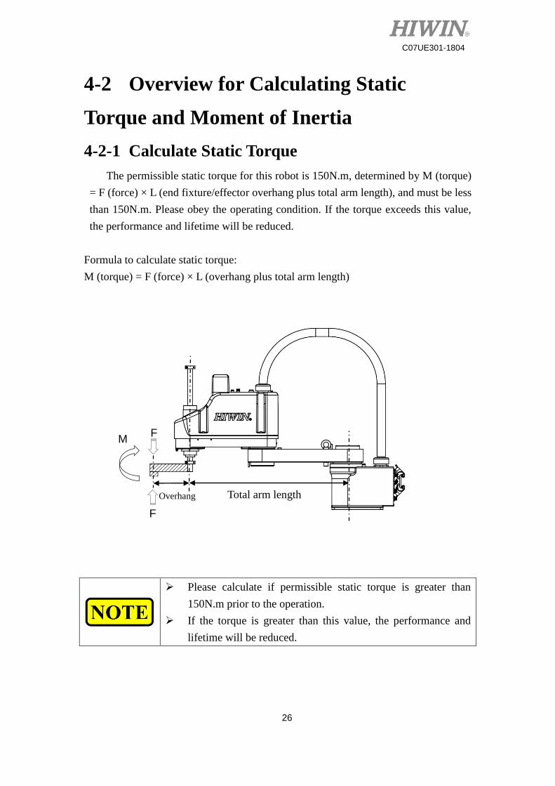
The permissible static torque for this robot is 150N.m, determined by M (torque)
= F (force) × L (end fixture/effector overhang plus total arm length), and must be less
than 150N.m. Please obey the operating condition. If the torque exceeds this value,
the performance and lifetime will be reduced.
Formula to calculate static torque:
M (torque) = F (force) × L (overhang plus total arm length)
Please calculate if permissible static torque is greater than
150N.m prior to the operation.
If the torque is greater than this value, the performance and
lifetime will be reduced.
Total arm length Overhang
F
F
M
27
C07UE301-1804
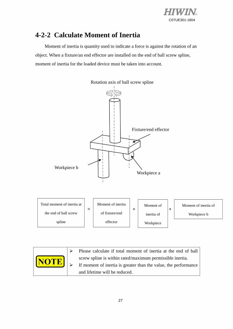
4-2-2 Calculate Moment of Inertia
Moment of inertia is quantity used to indicate a force is against the rotation of an
object. When a fixture/an end effector are installed on the end of ball screw spline,
moment of inertia for the loaded device must be taken into account.
Please calculate if total moment of inertia at the end of ball
screw spline is within rated/maximum permissible inertia.
If moment of inertia is greater than the value, the performance
and lifetime will be reduced.
Rotation axis of ball screw spline
Fixture/end effector
Workpiece a Workpiece b
Total moment of inertia at
the end of ball screw
spline
= Moment of inertia
of fixture/end
effector
+ Moment of
inertia of
Workpiece
+ Moment of inertia of
Workpiece b
28
C07UE301-1804
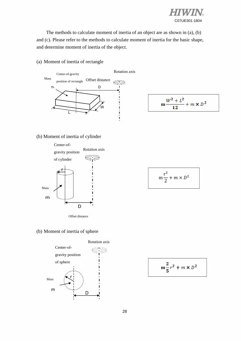
The methods to calculate moment of inertia of an object are as shown in (a), (b)
and (c). Please refer to the methods to calculate moment of inertia for the basic shape,
and determine moment of inertia of the object.
(a) Moment of inertia of rectangle
(b) Moment of inertia of cylinder
(b) Moment of inertia of sphere
mr2
2+𝑚 × 𝐷2
Mass
Center-of-gravity
position of rectangle
Rotation axis
Offset distance
Rotation axis Center-of-
gravity position
of cylinder
Mass
Mass
Rotation axis
Offset distance
Center-of-
gravity position
of sphere
29
C07UE301-1804
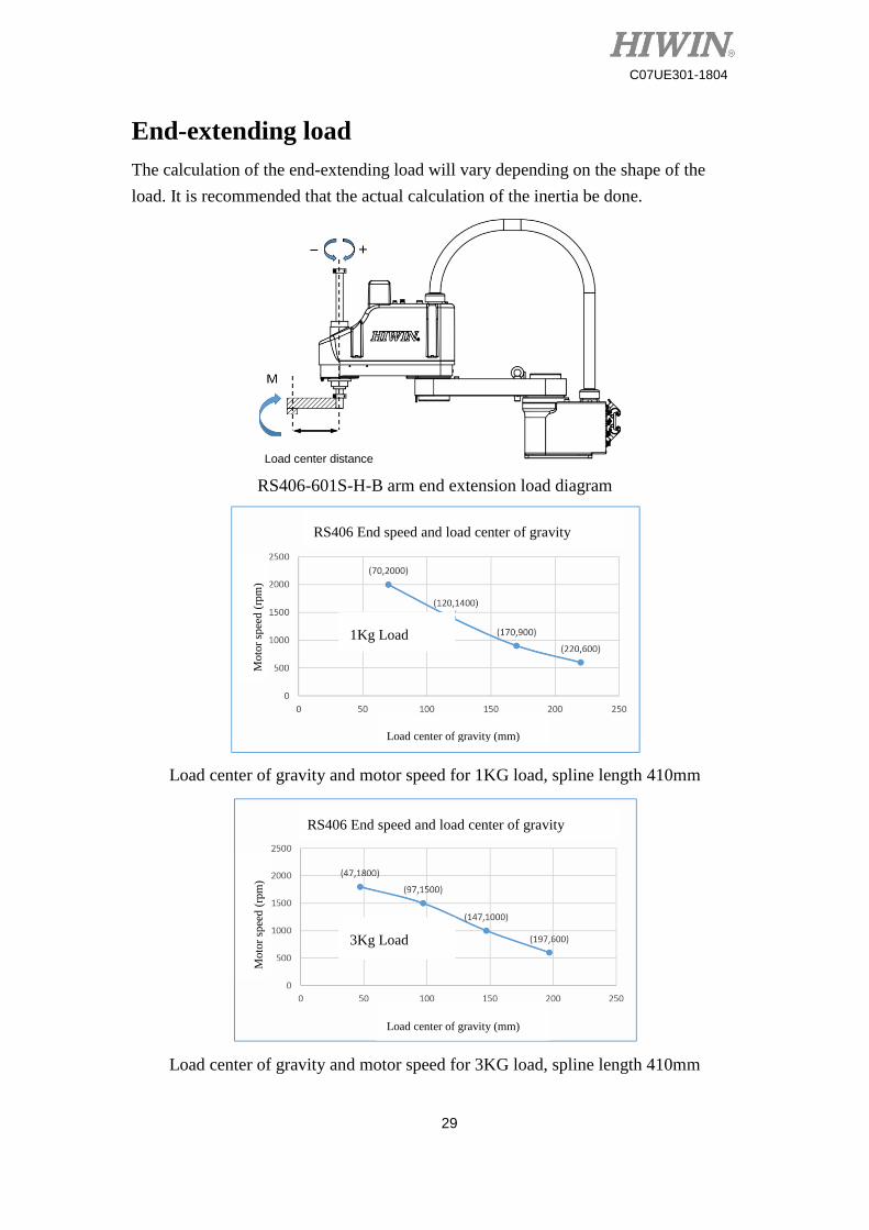
End-extending load
The calculation of the end-extending load will vary depending on the shape of the
load. It is recommended that the actual calculation of the inertia be done.
RS406-601S-H-B arm end extension load diagram
Load center of gravity and motor speed for 1KG load, spline length 410mm
Load center of gravity and motor speed for 3KG load, spline length 410mm
Load center distance
RS406 End speed and load center of gravity
Load center of gravity (mm)
Load center of gravity (mm)
RS406 End speed and load center of gravity
Moto
r sp
eed
(rp
m)
Moto
r sp
eed
(rp
m)
1Kg Load
3Kg Load
30
C07UE301-1804
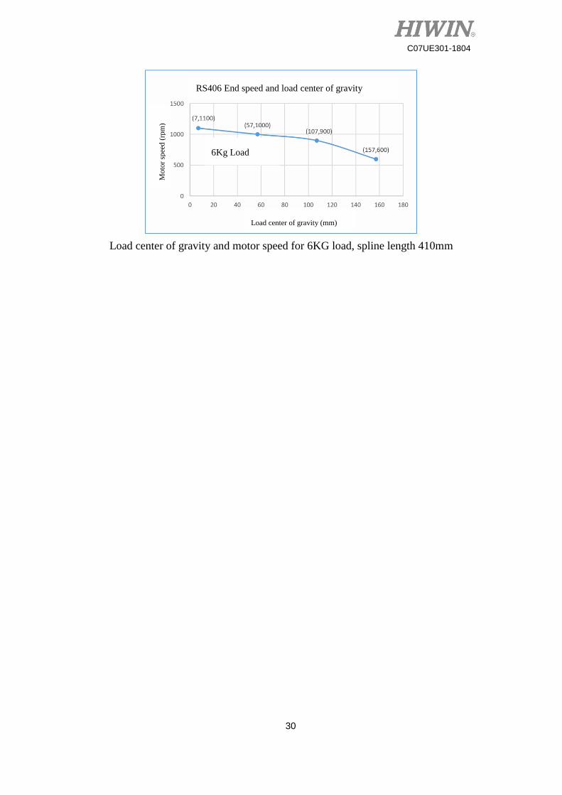
Load center of gravity and motor speed for 6KG load, spline length 410mm
Load center of gravity (mm)
RS406 End speed and load center of gravity
Moto
r sp
eed
(rp
m)
6Kg Load
31
C07UE301-1804
Maintenance
32
C07UE301-1804
5 Robot Maintenance In order to ensure the robot can efficiently operate and protect the operator safety,
please periodically maintain the robot according to the following sections. Don’t
disassemble the motor, decelerator and ball screw spline for the maintenance by
yourself to influence the accuracy of the robot. If there is any failure, please contact the
agent.
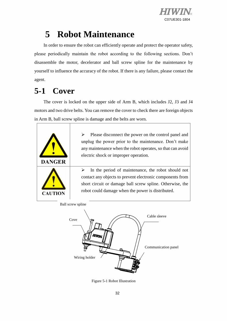
5-1 Cover
The cover is locked on the upper side of Arm B, which includes J2, J3 and J4
motors and two drive belts. You can remove the cover to check there are foreign objects
in Arm B, ball screw spline is damage and the belts are worn.
Please disconnect the power on the control panel and
unplug the power prior to the maintenance. Don’t make
any maintenance when the robot operates, so that can avoid
electric shock or improper operation.
In the period of maintenance, the robot should not
contact any objects to prevent electronic components from
short circuit or damage ball screw spline. Otherwise, the
robot could damage when the power is distributed.
Figure 5-1 Robot Illustration
Cove
r
Ball screw spline
Cable sleeve
Communication panel
Wiring holder
33
C07UE301-1804
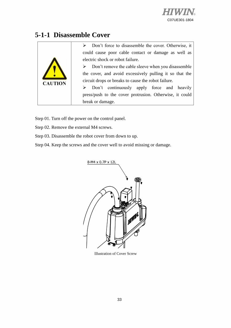
5-1-1 Disassemble Cover
Step 01. Turn off the power on the control panel.
Step 02. Remove the external M4 screws.
Step 03. Disassemble the robot cover from down to up.
Step 04. Keep the screws and the cover well to avoid missing or damage.
Illustration of Cover Screw
Don’t force to disassemble the cover. Otherwise, it
could cause poor cable contact or damage as well as
electric shock or robot failure.
Don’t remove the cable sleeve when you disassemble
the cover, and avoid excessively pulling it so that the
circuit drops or breaks to cause the robot failure.
Don’t continuously apply force and heavily
press/push to the cover protrusion. Otherwise, it could
break or damage.
34
C07UE301-1804
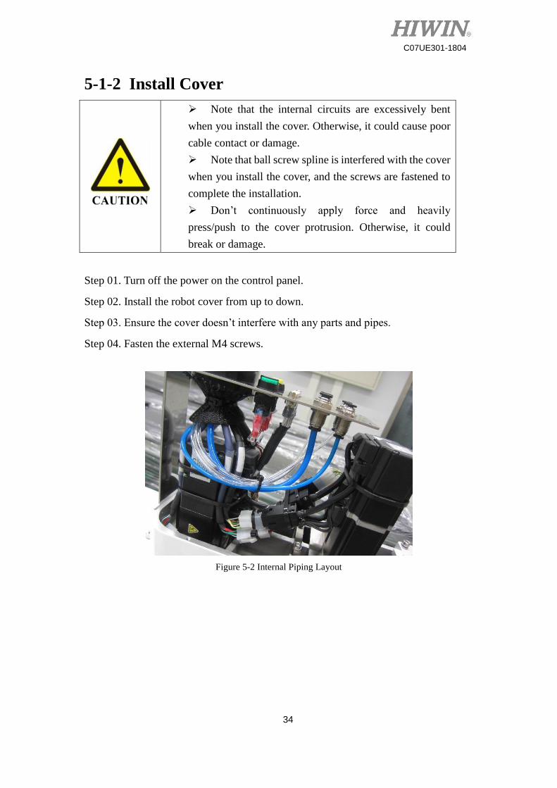
5-1-2 Install Cover
Note that the internal circuits are excessively bent
when you install the cover. Otherwise, it could cause poor
cable contact or damage.
Note that ball screw spline is interfered with the cover
when you install the cover, and the screws are fastened to
complete the installation.
Don’t continuously apply force and heavily
press/push to the cover protrusion. Otherwise, it could
break or damage.
Step 01. Turn off the power on the control panel.
Step 02. Install the robot cover from up to down.
Step 03. Ensure the cover doesn’t interfere with any parts and pipes.
Step 04. Fasten the external M4 screws.
Figure 5-2 Internal Piping Layout
35
C07UE301-1804
5-2 J3 & J4 Axes
J3 & J4 axes employ 100W servo motors. With the link of the belt wheel and the
belt, the rotational and linear motions of ball screw spline are controlled. A user can
remove the cover to check there is any failure inside the Arm B.
Please press the Emergency Stop button before the
maintenance. Don’t make any maintenance when the robot
runs, so that the operators could be hit or the incorrect run
could take place.
Don’t remove J3 & J4 motors without the
authorization to influence the running accuracy of the
robot.
36
C07UE301-1804
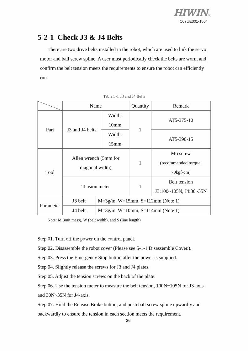
5-2-1 Check J3 & J4 Belts
There are two drive belts installed in the robot, which are used to link the servo
motor and ball screw spline. A user must periodically check the belts are worn, and
confirm the belt tension meets the requirements to ensure the robot can efficiently
run.
Table 5-1 J3 and J4 Belts
Name Quantity Remark
Part J3 and J4 belts
Width:
10mm 1
AT5-375-10
Width:
15mm AT5-390-15
Tool
Allen wrench (5mm for
diagonal width) 1
M6 screw
(recommended torque:
70kgf-cm)
Tension meter 1 Belt tension
J3:100~105N, J4:30~35N
Parameter J3 belt M=3g/m, W=15mm, S=112mm (Note 1)
J4 belt M=3g/m, W=10mm, S=114mm (Note 1)
Note: M (unit mass), W (belt width), and S (line length)
Step 01. Turn off the power on the control panel.
Step 02. Disassemble the robot cover (Please see 5-1-1 Disassemble Cover.).
Step 03. Press the Emergency Stop button after the power is supplied.
Step 04. Slightly release the screws for J3 and J4 plates.
Step 05. Adjust the tension screws on the back of the plate.
Step 06. Use the tension meter to measure the belt tension, 100N~105N for J3-axis
and 30N~35N for J4-axis.
Step 07. Hold the Release Brake button, and push ball screw spline upwardly and
backwardly to ensure the tension in each section meets the requirement.

37
C07UE301-1804
Step 08. Fasten the screws for J3 and J4 plates.
Step 09. Turn off the power on the control panel.
Step 10. Install the robot cover.
38
C07UE301-1804
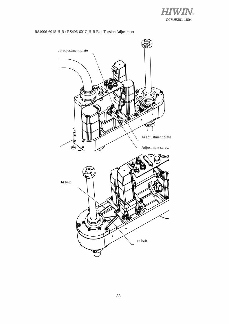
RS4006-601S-H-B / RS406-601C-H-B Belt Tension Adjustment
J3 adjustment plate
J4 adjustment plate
Adjustment screw
J4 belt
J3 belt
39
C07UE301-1804
5-3 Grease Lubrication
There are many movable joints and parts on the SCARA Robot. The decelerator
and ball screw spline must be periodically serviced and maintained. Because ball screw
spline is exposed in the open environment for long time to easily accumulate dust or
insufficiently lubricate, a user must pay more attention so that the robot can efficiently
operate.
5-3-1 Lubrication of Ball Screw Spline
Ball screw spline is used for the rotation (J3-axis) and linear (J4-axis) motion of
the robot, supported by two sets of nut respectively. The bearing in the nut needs to be
periodically greased, and the external grooves of ball screw spline must be kept clean,
so that ball screw spline can smoothly run.
Please press the Emergency Stop button and
disconnect the power prior to the maintenance. Don’t make
any maintenance when the robot operates, so that can avoid
electric shock or improper operation.
Don’t remove ball screw spline without the
authorization to influence the running accuracy of the
robot.
Lubrication of Ball Screw Spline
Lubrication
part Item Check Operation
Roller
spline
Lubrication
Check once per
three month
when the
running
distance reaches
100km.
Put new grease into lubrication nozzle
Recommended fill: 4.5c.c.
Ball screw
nut
Roller
spline
40
C07UE301-1804
Spline nut
Roller
spline
bearing
Ball screw
spline
Uniformly apply grease on the screw
surface in the grooves.
Recommended fill: 5c.c.
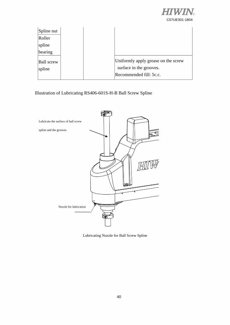
Illustration of Lubricating RS406-601S-H-B Ball Screw Spline
Lubricating Nozzle for Ball Screw Spline
Lubricate the surface of ball screw
spline and the grooves
Nozzle for lubrication
41
C07UE301-1804
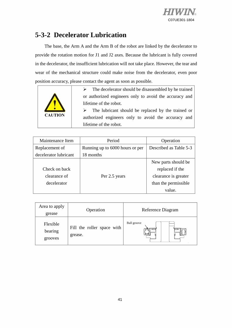
5-3-2 Decelerator Lubrication
The base, the Arm A and the Arm B of the robot are linked by the decelerator to
provide the rotation motion for J1 and J2 axes. Because the lubricant is fully covered
in the decelerator, the insufficient lubrication will not take place. However, the tear and
wear of the mechanical structure could make noise from the decelerator, even poor
position accuracy, please contact the agent as soon as possible.
The decelerator should be disassembled by he trained
or authorized engineers only to avoid the accuracy and
lifetime of the robot.
The lubricant should be replaced by the trained or
authorized engineers only to avoid the accuracy and
lifetime of the robot.
Maintenance Item Period Operation
Replacement of
decelerator lubricant
Running up to 6000 hours or per
18 months
Described as Table 5-3
Check on back
clearance of
decelerator
Per 2.5 years
New parts should be
replaced if the
clearance is greater
than the permissible
value.
Area to apply
grease Operation Reference Diagram
Flexible
bearing
grooves
Fill the roller space with
grease.
Ball groove
42
C07UE301-1804
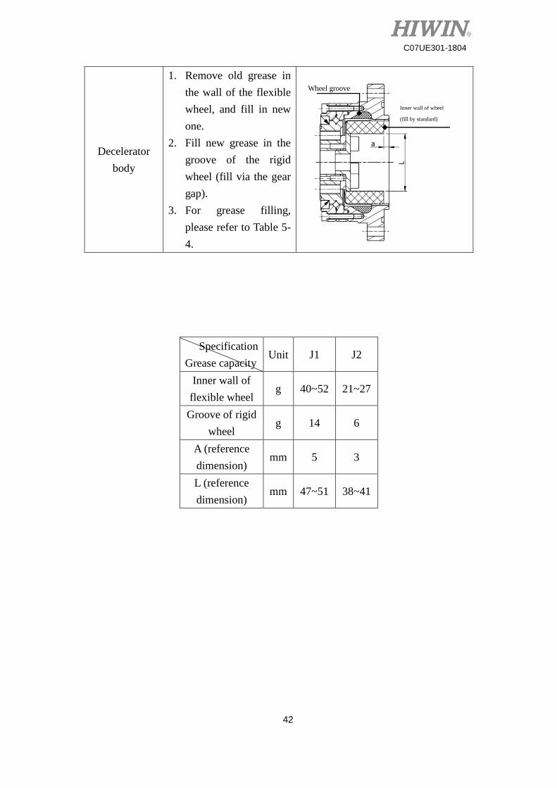
Decelerator
body
1. Remove old grease in
the wall of the flexible
wheel, and fill in new
one.
2. Fill new grease in the
groove of the rigid
wheel (fill via the gear
gap).
3. For grease filling,
please refer to Table 5-
4.
Specification
Grease capacity Unit J1 J2
Inner wall of
flexible wheel g 40~52 21~27
Groove of rigid
wheel g 14 6
A (reference
dimension) mm 5 3
L (reference
dimension) mm 47~51 38~41
Wheel groove
Inner wall of wheel
(fill by standard)
43
C07UE301-1804
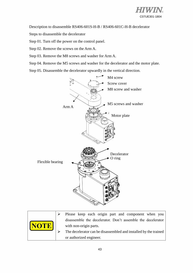
Description to disassemble RS406-601S-H-B / RS406-601C-H-B decelerator
Steps to disassemble the decelerator
Step 01. Turn off the power on the control panel.
Step 02. Remove the screws on the Arm A.
Step 03. Remove the M8 screws and washer for Arm A.
Step 04. Remove the M5 screws and washer for the decelerator and the motor plate.
Step 05. Disassemble the decelerator upwardly in the vertical direction.
Please keep each origin part and component when you
disassemble the decelerator. Don’t assemble the decelerator
with non-origin parts.
The decelerator can be disassembled and installed by the trained
or authorized engineer.
Decelerator O ring
Flexible bearing
Arm A M5 screws and washer
M8 screw and washer
Screw cover
M4 screw
Motor plate
44
C07UE301-1804
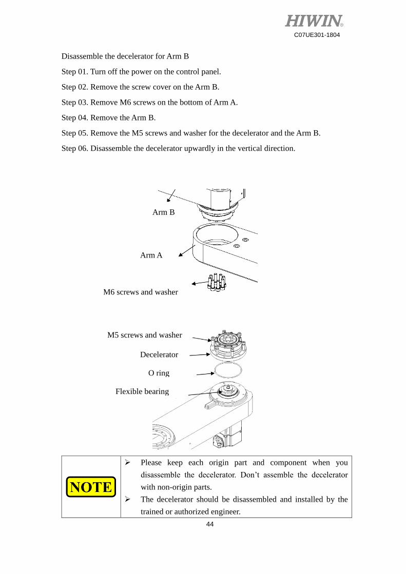
Disassemble the decelerator for Arm B
Step 01. Turn off the power on the control panel.
Step 02. Remove the screw cover on the Arm B.
Step 03. Remove M6 screws on the bottom of Arm A.
Step 04. Remove the Arm B.
Step 05. Remove the M5 screws and washer for the decelerator and the Arm B.
Step 06. Disassemble the decelerator upwardly in the vertical direction.
Please keep each origin part and component when you
disassemble the decelerator. Don’t assemble the decelerator
with non-origin parts.
The decelerator should be disassembled and installed by the
trained or authorized engineer.
Arm B
Arm A
M6 screws and washer
M5 screws and washer
Decelerator
O ring
Flexible bearing
45
C07UE301-1804
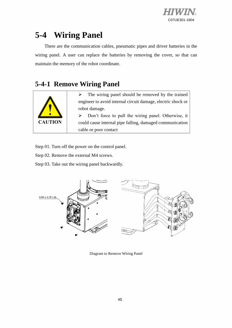
5-4 Wiring Panel
There are the communication cables, pneumatic pipes and driver batteries in the
wiring panel. A user can replace the batteries by removing the cover, so that can
maintain the memory of the robot coordinate.
5-4-1 Remove Wiring Panel
The wiring panel should be removed by the trained
engineer to avoid internal circuit damage, electric shock or
robot damage.
Don’t force to pull the wiring panel. Otherwise, it
could cause internal pipe falling, damaged communication
cable or poor contact
Step 01. Turn off the power on the control panel.
Step 02. Remove the external M4 screws.
Step 03. Take out the wiring panel backwardly.
Diagram to Remove Wiring Panel
46
C07UE301-1804
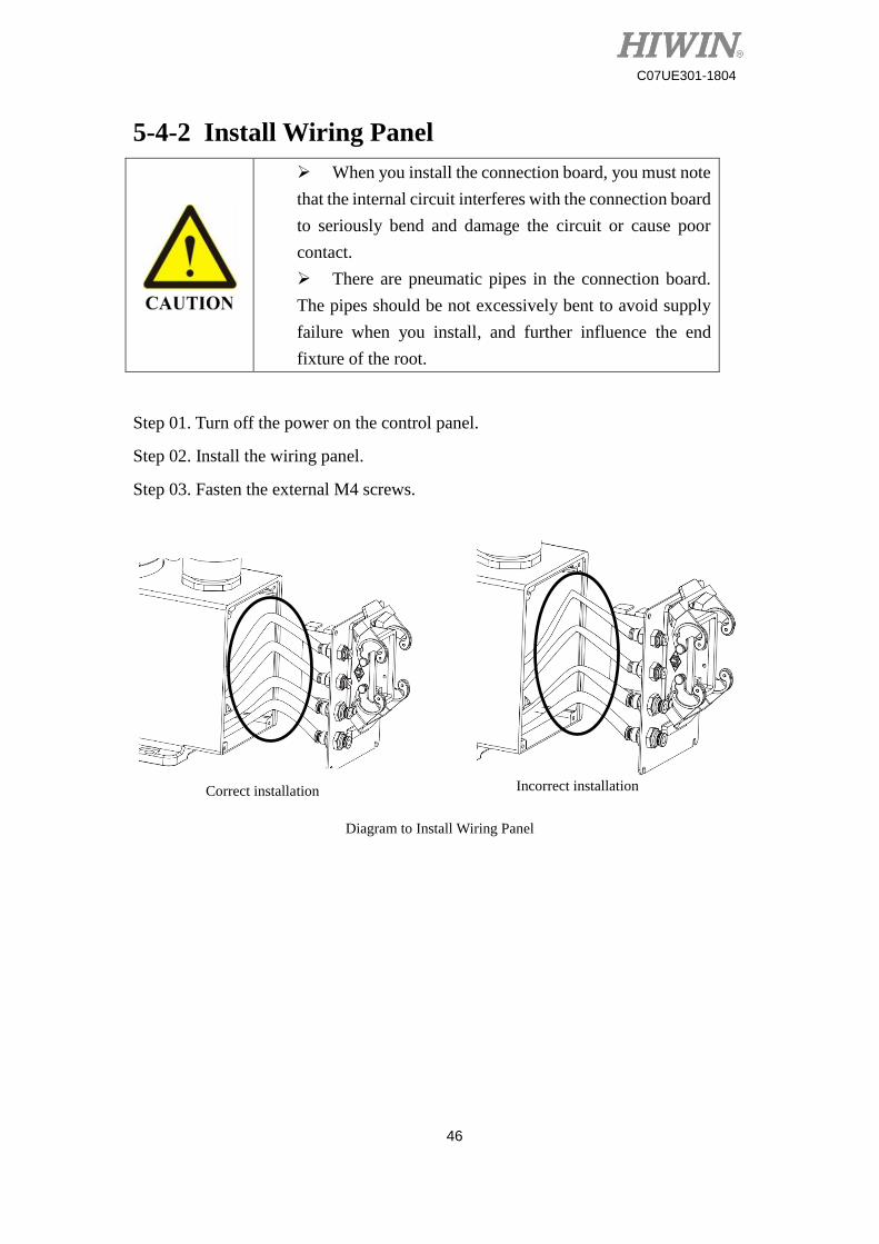
5-4-2 Install Wiring Panel
When you install the connection board, you must note
that the internal circuit interferes with the connection board
to seriously bend and damage the circuit or cause poor
contact.
There are pneumatic pipes in the connection board.
The pipes should be not excessively bent to avoid supply
failure when you install, and further influence the end
fixture of the root.
Step 01. Turn off the power on the control panel.
Step 02. Install the wiring panel.
Step 03. Fasten the external M4 screws.
Diagram to Install Wiring Panel
Correct installation Incorrect installation
47
C07UE301-1804
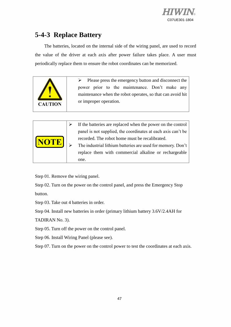
5-4-3 Replace Battery
The batteries, located on the internal side of the wiring panel, are used to record
the value of the driver at each axis after power failure takes place. A user must
periodically replace them to ensure the robot coordinates can be memorized.
Please press the emergency button and disconnect the
power prior to the maintenance. Don’t make any
maintenance when the robot operates, so that can avoid hit
or improper operation.
If the batteries are replaced when the power on the control
panel is not supplied, the coordinates at each axis can’t be
recorded. The robot home must be recalibrated.
The industrial lithium batteries are used for memory. Don’t
replace them with commercial alkaline or rechargeable
one.
Step 01. Remove the wiring panel.
Step 02. Turn on the power on the control panel, and press the Emergency Stop
button.
Step 03. Take out 4 batteries in order.
Step 04. Install new batteries in order (primary lithium battery 3.6V/2.4AH for
TADIRAN No. 3).
Step 05. Turn off the power on the control panel.
Step 06. Install Wiring Panel (please see).
Step 07. Turn on the power on the control power to test the coordinates at each axis.
48
C07UE301-1804
Standard SCARA, Battery Holder on Wiring Board
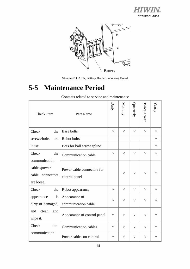
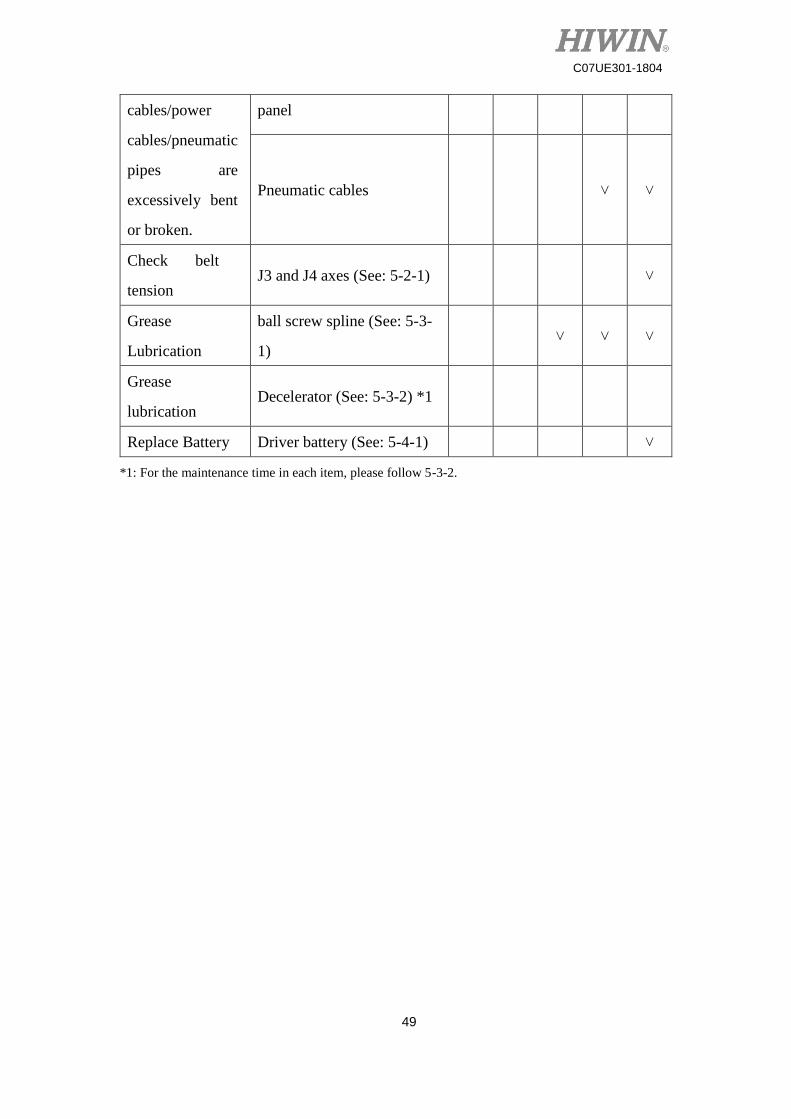
5-5 Maintenance Period
Contents related to service and maintenance
Check Item Part Name
Daily
Month
ly
Quarterly
Tw
ice a year
Yearly
Check the
screws/bolts are
loose.
Base bolts ˅ ˅ ˅ ˅ ˅
Robot bolts ˅
Bots for ball screw spline ˅
Check the
communication
cables/power
cable connectors
are loose.
Communication cable ˅ ˅ ˅ ˅ ˅
Power cable connectors for
control panel ˅ ˅ ˅ ˅
Check the
appearance is
dirty or damaged,
and clean and
wipe it.
Robot appearance ˅ ˅ ˅ ˅ ˅
Appearance of
communication cable ˅ ˅ ˅ ˅ ˅
Appearance of control panel ˅ ˅ ˅ ˅ ˅
Check the
communication
Communication cables ˅ ˅ ˅ ˅ ˅
Power cables on control ˅ ˅ ˅ ˅ ˅
Battery
49
C07UE301-1804
cables/power
cables/pneumatic
pipes are
excessively bent
or broken.
panel
Pneumatic cables ˅ ˅
Check belt
tension J3 and J4 axes (See: 5-2-1) ˅
Grease
Lubrication
ball screw spline (See: 5-3-
1) ˅ ˅ ˅
Grease
lubrication Decelerator (See: 5-3-2) *1
Replace Battery Driver battery (See: 5-4-1) ˅
*1: For the maintenance time in each item, please follow 5-3-2.
50
C07UE301-1804
6 Troubleshooting
6-1 Offset
Upon the position is offset when the robot operates, please immediately stop all
operations and execute the home command, so that the robot can read the relative
position at each station. If the condition for the serious position offset can’t be
modified by resetting the home, please contact customer service for calibration.
6-2 Overheat
The robot is equipped with a mechanism of temperature protection. The incorrect
working temperature will influence the operations. A user must maintain the
appropriate environment temperature. As soon as the temperature rise in the system
takes place owing to the fan failure, the robot will stop the operation. Please contact
customer to replace the fan.
The motor drivers at each axis are equipped with a protection mechanism. The
high temperature or acceleration/deceleration will stop the operation of the robot. You
must recover the system setting by restarting it. A user can keep the robot normally
operating by changing the system setting.
Lower acceleration and velocity when the robot runs.
Reduce the time when the robot continuously runs.
6-3 Noise from Machine
The robot comprises several slide and rotation parts and components. It is
recommended a user periodically lubricate each part and component, so that the robot
can smoothly operate. As soon as noise is generated when the robot operates, please
contact customer service for check and maintenance.
51
C07UE301-1804
6-4 Jog
When you evaluate to operate the robot, please carefully read the specifications.
The efficiency of the robot depends on the fixtures or objects loaded on ball screw
spline. If the loads exceed the requirements, a user can maintain the normal operation
of the robot by changing the system setting or seek the assistance from customer
service.
Reduce acceleration and velocity when the robot operates.
Modify the fixture dimension and weight.
52
C07UE301-1804
Opinion Response
Issue Actual condition
Suggestion:
E-mail: [email protected]
Customer hotline: +866-4-23594510
1. HIWIN is the registered trademark of HIWIN Technologies Corp.. For your protection; To avoid counterfeit products, be certain you are buying genuine HIWIN products before purchase.
2. Actual products may be different from the specifications and photos in this catalog. The differences in appearances or specifications may be caused by, among other things, product improvements.
3. HIWIN will not sell or export those techniques and products restricted under the "Foreign Trade Act" and relevant regulations. Any export of restricted products should be approved by competent authorities in accordance with relevant laws, and shall not be used to manufacture or develop nuclear, biochemical, missile and other military weapons.
4. HIWIN website for patented product directory: http://www.hiwin.tw/Products/Products_patents.aspx
Publication Date:April 2018, first edition
SCARA Robot - RS406 Maintenance Manual
Copyright © HIWIN Technologies Corp.

Copyright © HIWIN Technologies Corp.©2018 FORM C07UE301-1804 (PRINTED IN TAIWAN)The specifications in this catalog are subject to change without notification.
Subsidiaries & R&D Centers
HIWIN Schweiz GmbHJONA, [email protected]
HIWIN s.r.o.BRNO, CZECH [email protected]
HIWIN [email protected]
HIWIN KOREASUWON‧MASAN, [email protected]
HIWIN CHINASUZHOU, [email protected]
Mega-Fabs Motion System, Ltd.HAIFA, [email protected]
HIWIN GmbHOFFENBURG, [email protected]
HIWIN JAPANKOBE‧TOKYO‧NAGOYA‧NAGANO‧TOHOKU‧SHIZUOKA.HOKURIKU‧HIROSHIMA‧FUKUOKA‧KUMAMOTO, [email protected]
HIWIN USACHICAGO‧SILICON VALLEY, U.S.A. [email protected]
HIWIN SrlBRUGHERIO, [email protected]
HIWIN TECHNOLOGIES CORP.No. 7, Jingke Road, Taichung Precision Machinery Park,Taichung 40852, TaiwanTel: +886-4-23594510Fax: [email protected]
Related Documents