Purchasing guides for the electronics industry www.eecatalog.com/sensors EE C atalog Engineers’ Guide to Sensors & MEMS Digital and Physical Worlds Collide Sensor Innovation Enables New Applications MEMS Integration Challenges: Today and Tomorrow Augmented Reality: The Complexity of Simplicity Scan this QR code to subscribe Gold Sponsors Supporting Organization

Welcome message from author
This document is posted to help you gain knowledge. Please leave a comment to let me know what you think about it! Share it to your friends and learn new things together.
Transcript

Purchasing guides for the electronics industry
www.eecatalog.com/sensorsEECatalog
Engineers’ Guide to Sensors & MEMSDigital and Physical Worlds Collide
Sensor Innovation Enables New Applications MEMS Integration Challenges: Today and Tomorrow
Augmented Reality: The Complexity of Simplicity
Scan this QR code to subscribe
Gold Sponsors Supporting Organization

High Performance, Low Power Accelerometers, Gyros and 6-Axis Solutions From Kionix
Kionix, Inc. Worldwide Headquarters | 36 Thornwood Drive, Ithaca, NY 14850 USAPhone: 607.257.1080 | www.kionix.com
Accelerometers
KXtJ2 – 2x2x0.9mm, 12-pin accelerometer• Low-noise and low-power (2 µA at standby; 10 µA at
low resolution; 135 µA at high resolution)• Up to 14-bit resolution• Low-power, embedded wake-up function• Outstanding stability with excellent combination of
thermal, shock and reflow performance• Internal voltage regulator• 1.8V to 3.6V operating voltage• Also available in a 3x3x0.9mm, 10-pin, LGA package –
the KXCJ9
KXcNl – 3x3x0.9mm, 16-pin, dual state machine device• Features dual user-programmable state machines• User-selectable ± 2g, 4g, 6g, or 8g range• Supports I2C High Speed, Fast Speed, and Standard
Speed interfaces• 1.7V to 3.6V operating voltage• Available library of pre-written state programs
6-AXIS ACCeLerOmeter/GyrOSCOpe
KXG02 – Six-axis accelerometer/gyroscope combination product in a single 4x4x0.9mm, 24-pin package• Industry-leading 4.0 mA operating current• Full-scale range of ±256, ±512, ±1024, and ±2048 °/sec• Low noise at 0.03 deg/sec/√Hz typical• Low-power, embedded wake-up function with an
interrupt engine that allows the user to power down other systems until needed
• Accelerometer with up to 16-bit resolution • 1024 byte FIFO buffer and auxiliary I2C bus to collect
data from internal and external sensors and send packets of data to the host processor
GyrOSCOpe
KGy23 - 4x4x0.9mm, 24-pin, tri-axis gyroscope• 3.75 mA operating current• Full-scale range of ±256, ±512, ±1024, and ±2048 °/sec• I2C or SpI digital serial interface bus communication• Low noise at 0.03 deg/sec/√Hz typical• User-definable bandwidth• embedded temperature sensor• Accepts supply voltages between 2.6V and 3.3V and
digital communication voltages between 1.8V and 3.3V


Engineers’ Guide to Sensors & MEMS 20122
Welcome to the 2012 Engineers’ Guide to Sensors & MEMS
As we come on the scene, market growth is strong – primarily driven by demand for consumer devices. But as senior editor Chris Ciufo discovers (“MEMS Trends: Smaller, Cheaper, Everywhere”), the picture isn’t all rosy. Some markets are saturating, and a yet-to-be-discovered killer app would go a long way towards cementing the industry’s position. In the meantime, though, there’s plenty of innovation going on.
In this issue, the role of MEMS and sensors gets top billing as augmented reality (AR) and contextual awareness move past the “cool” factor to begin driving a wide range of high-utility applications in everything from medical to military (“Context is Key as Augmented Reality Takes Off”). As Dirk Groten, Layar CTO, says, “AR will become useful, not as a goal but as a means.” Of course, the development challenges are far from trivial, with small mobile devices combining multiple types of sensors and technologies in a single device, incorporating complex image-recognition systems, and requiring fast storage and high data-transfer rates. Freescale’s Stéphane Gervais-Ducouret addresses many of those challenges in “Augmented Reality: The Complexity of Simplicity.”
On the healthcare side, MEMS devices are moving quickly into home medical devices and monitors – an evolution that proponents hope will bolster growth in both markets. TI and Texas Tech University showcase one such application, designed to help prevent debilitating falls by the elderly by pairing a MEMS accelerometer and MEMS gyroscope with a microcontroller (MCU) and radio frequency (RF) transceiver to track a person’s gait and posture (“MEMS Healthcare Applications Innovate Prevention and Treatment”).
On the development side, the challenges around MEMS integration continue to grow. MEMS are being combined with CMOS electronics in approaches ranging from a monolithic process to separate pack-ages, requiring a new generation of design tools to address all levels of integration. As Coventor’s Stephen Breit says in “MEMS Integration Challenges, Today and Tomorrow”: “To put it simply, one supplier’s system is another’s component.”
There’s all this and more inside these pages, and even more available online at www.eecatalog.com/sensors. Read, enjoy – visit often!
Cheryl Berglund CoupéEditor, EECatalog.com
P.S. To subscribe to our series of Engineers’ Guides for embedded developers and engineers, visit:
www.eecatalog.com/subscribe
Engineers’ Guide to Sensors & MEMS 2012www.eecatalog.com/sensors
VP/Associate PublisherClair Bright [email protected](415) 255-0390 ext. 15
EditorialEditorial DirectorJohn Blyler [email protected](503) 614-1082EditorCheryl Berglund Coupé [email protected] EditorChris A. Ciufo [email protected]
Creative/ProductionProduction Manager Spryte Heithecker
Graphic DesignersKeith Kelly - SeniorNicky Jacobson
Production Assistant Jenn Burkhardt
Senior Web DeveloperMariam Moattari
Advertising/Reprint SalesVP/Associate Publisher Embedded Electronics Media GroupClair Bright [email protected](415) 255-0390 ext. 15
Sales ManagerMichael [email protected] (415) 255-0390 ext. 17
Marketing/CirculationJenna Johnson
To Subscribewww.eecatalog.com/subscribe
Extension Media, LLCCorporate OfficePresident and PublisherVince [email protected]
Vice President, Sales Embedded Electronics Media GroupClair [email protected]
Vice President, Marketing and Product DevelopmentKaren [email protected]
Vice President, Business DevelopmentMelissa [email protected]
Special Thanks to Our Sponsors
The Engineers’ Guide to Sensors & MEMS 2012 is published by Extension Media LLC. Extension Media makes no warranty for the use of its products and assumes no responsibility for any errors which may appear in this Catalog nor does it make a commitment to update the information contained herein. Engineers’ Guide to Sensors & MEMS is Copyright ®2012Extension Media LLC. No information in this Catalog may be reproduced without expressed written permission from Extension Media @ 1786 18th Street, San Francisco, CA 94107-2343.
All registered trademarks and trademarks included in this Catalog are held by their respective companies. Every attempt was made to include all trademarks and registered trademarks where indicated by their companies.
SEMI-Deco_8.375x10.875_PQ.pdf 5/23/12 5:29:06 PM
EECatalog

SEMI-Deco_8.375x10.875_PQ.pdf 5/23/12 5:29:06 PM

Engineers’ Guide to Sensors & MEMS 20124
In this Issue
MEMS Pro v8.0
By SoftMEMS LLC ....................................................................................................................................... 6
Use of Hall-Effect Rotary-Position Sensors in Transportation Applications
By Chris Gottlieb, Honeywell Sensing and Control ..................................................................................... 8
MEMS Integration Challenges: Today and Tomorrow
By Dr. Stephen Breit, Coventor, Inc. ...........................................................................................................12
MEMS and Packaging Hold Keys to Radio Connectivity
By John Blyler, Editorial Director ...............................................................................................................15
MEMS Healthcare Applications Innovate Prevention and Treatment
By Allen Bowling, TI ...................................................................................................................................17
Digital and Physical Worlds Collide
By Cheryl Coupé, Editor .............................................................................................................................19
Mechanical Meets Electrical
By Ed Sperling, Contributing Editor ............................................................................................................22
MEMS Intertial Sensing: The Five Motion Senses
By Rob O’Reilly and Harvey Weinberg, Analog Devices ............................................................................24
MEMS Trends: Smaller, Cheaper, Everywhere
By Chris A. Ciufo, Senior Editor ................................................................................................................ 28
Augmented Reality: The Complexity of Simplicity
By Stéphane Gervais-Ducouret, Freescale ............................................................................................... 32
Cover image courtesy of Analog Devices

and Top Stories
Industry Research
Calendar of Events

Engineers’ Guide to Sensors & MEMS 20126
MEMS Pro is a flexible, powerful, easy-to-use CAD tool suite for the design and analysis of micro-electro-mechanical systems (MEMS). It offers an integrated solution for the design process that shortens development time while providing
designers reliable analysis for manufacture. Functionalities include mixed MEMS/IC schematic capture and simula-tion, full custom mask layout capability and verification, 3D model generation and visualization, behavioral model creation and links to 3D analysis packages.
FeaturesSystem-level Tools: MEMS Pro provides system-level design capability through fully hierarchical schematic cap-ture and behavioral level simulation of MEMS devices with electronics and packaging. A library of composable MEMS models is included parameterized by process parameters, material properties and device dimensions. The models are represented with 6DOF-mechanical, thermal, mag-netic, f luidic, optical, and electro-static domains. MEMS models are represented in high level behavioral languages, SPICE, C-code, or data tables.
• Simulationmodes include AC, DC operating point, DCtransfer sweep, Fourier, Noise, Transient, Transfer func-tion, and Parametric Sweep.
• Powerful optimization algorithms determine device orprocess parameters that will optimize MEMS design performance.
• Statisticalanalysisallowsdesignerstosimulateprocesscorners, run Monte Carlo simulations with statistical distributions of process and geometrical parameters, create response surface models, and perform sensitivity analysis to understand which geometrical or process parameters most effect device performance and esti-mate yield.
For designs that contain both MEMS and IC devices, MEMS Pro allows easy creation and modification of schematics, and generates netlists for simulation, optimization, sta-tistical analysis, and layout verification. The simulation library includes symbols and parameterized behavioral models for a variety of MEMS components. The integrated simulation environment allows users to probe signals of interest on the schematic and simulation waveforms are automatically displayed.
Modeling Tools: MEMS Modeler automatically gen-erates behavioral models ready for system simulation with electronics and packaging from 3D data from finite element analysis programs. Complex, finite element models involving a large number of degrees of freedom are reduced to behavioral models with a few master degrees of freedom. Users can also create their own models from analytical equations and the tool generates simu-lation- ready descriptions in a variety of popular formats. MEMS Modeler facilitates the bridge between 3D and system simulations enabling design teams to work together.
MEMS Pro v8.0By SoftMEMS LLC
Copyright SoftMEMS 2012.
MEMS Pro is a trademark of SoftMEMS.
AutoCAD is a trademark of Autodesk.
ANSYS is a trademark of ANSYS Inc.

www.eecatalog.com/sensors 7
Layout Editing: MEMS Pro’s physical design environ-ment includes a fully hierarchical and full custom mask editor engineered for MEMS and IC design. The program uses an intuitive interface and provides specific MEMS-related capabilities that greatly reduce layout time. A curve generator allows designers to create MEMS primi-tives, such as splines, fillets and general equation-based curves. The Shape Recovery Tool recovers shapes such as circles, torii, etc from multi-sided polygons found in formats such as GDS II. A DXF translator is provided for a link with AutoCAD. The EasyMEMS tool helps to automate tasks that are time-consuming for creating MEMS mask layout such as creating polar arrays. Useful macros include the generation of holes and dimples to properly release MEMS structures.
A Library of scalable MEMS device layouts is provided through a handy graphical library browser. The library devices are linked to user-specified or foundry design rules to ensure manufacturability. The library includes thermal, mechanical, optical, f luidic, and electrostatic devices. A powerful interface is included for automating, customizing and extending the layout editor command and function set using the C language. Popular output for-mats are supported so mask designs are “foundry ready”.
MEMS Verification provides a configurable Design Rule Checker that verifies MEMS layout against fabrication requirements to prevent costly design errors. In addi-tion, application and device specific context sensitive rule checking is included. An Extractor generates a SPICE netlist from a MEMS layout including MEMS devices, their parameters and multi-domain connectivity. The LVS (Layout vs. Schematic) tool takes the extracted data and compares it against the SPICE netlist from the sche-matic editor to ensure that the mask layout captures the designer’s intent.
The 3D Solid Modeler creates a 3D view of a MEMS device from a selected layout area and fabrication process description. An easy to use Technology Manager allows users to enter fabrication process steps and sequences as well as material properties. Surface and bulk micro-machining process steps such as material deposit, etch,
mechanical polish, diffusion, growth, electroplating and wafer manipulation steps are supported. The 3D model may be scaled, and a subset of mask layers may be selected for view. Models can be viewed with rotations, zooms, preset views, step-by-step display of the fabrication sequence, and can be animated to show process sequences. The Cross Section Viewer displays a cutaway view in the z-dimension based on a user-specified cut line.
Boundary conditions may be defined on mask layout and can be automatically transferred along with either a 2D or 3D model to third party analysis or viewing programs in popular formats (e.g. SAT, APDL and IGES). Models may be “defeatured” for efficient FEM meshing. A MEMS-specific mesher creates efficient meshes for analysis. 3D-To-Layout converts 3D solid models in ANSYS into 2D mask layouts using user-specified fabrication process descriptions, enabling capture of device mask modifica-tions made in 3D analysis programs.
Foundry Modules enable targeting of specific process technologies, provide process-specific device intellectual property, and are fully integrated with SoftMEMS’ tool suites to ensure process compatibility and manufactur-ability with the world’s leading MEMS foundries. Foundry modules include mask and device design rules, mask layer descriptions, device descriptions for extraction, process parameters and material properties, and foundry fabrica-tion process sequence descriptions.
ContaCt InformatIon
SoftMEMS LLC2391 Nobili AveSanta Clara, CA 95051, USATel: +1 408 426 4301Fax: +1 408 379 2306

Engineers’ Guide to Sensors & MEMS 20128
EECatalog Special Feature
There are a wide range of components, switches and sen-sors found inside most motorized vehicles that are used for personal transportation or for heavy industry. One interesting class of components is Hall-effect rotary-posi-tion sensors that may potentially be used in applications such as cars, trucks, buses and boats.
Hall-effect rotary-position sensors are designed to measure the angle position of a moving element by utilizing a mag-netic field instead of mechanical brushes or dials. They use a magnetically biased, Hall-effect integrated circuit (IC) that senses rotary movement of the actuator shaft over a set operating range. Rotation of the actuator shaft changes a magnet’s position relative to the IC. The resulting flux density change is then converted to a linear output which can be used to provide feedback to either the operator or vehicle subsystem.
Solid-state Hall-effect technology provides non-contact operation. The internal section of the sensor uses a magnetic field, not a physical brush or wiper that is used in potentiometers. Wipers used in potentiometers can cause friction, which can reduce the product’s life. Using non-contact magnetic Hall-effect technology in a rotary-position sensor helps reduce worn-out mechanisms, lowers actuation torque and extends the product’s service life.
Hall-effect rotary-position sensors may be used in many harsh transportation and industrial applications at a com-petitive cost.
Potential Transportation Applications
Foot Pedal Position SensingIn heavy-duty equipment and other vehicles, Hall-effect rotary-position sensors may be used to replace the mechanical cable connection between the foot pedal and the engine. A mechan-ical cable can stretch or rust, potentially requiring regular maintenance and recalibration. Eliminating the mechanical cable can improve the engine control system response, benefit-ting the vehicle’s emission, improving reliability and reducing excess weight. This type of drive-by-wire system can be both safer and less expensive than cable-connected systems.
For example, a rotary-position sensor may be mounted adjacent to the pedal to measure how far down the pedal is pressed. The harder the operator presses, the deeper the pedal is depressed, allowing more fuel and air to be delivered to the engine so the vehicle moves faster. When the operator removes their foot from the pedal, the Hall-effect rotary-position sensor senses
Use of Hall-Effect Rotary-Position Sensors in Transportation ApplicationsDesigned to measure, monitor and provide feedback, Hall-effect rotary-position sensors are an integral component in many transportation and industrial applications.
By Chris Gottlieb, Honeywell Sensing and Control
Honeywell’s RTY Series Rotary Position Sensor may be used for foot pedal position sensing. Photo source attribution:© 2012 Honeywell International
Hall-effect rotary-position sensors may be used in many
harsh transportation and industrial applications at a
competitive cost.

Engineers’ Guide to Sensors & MEMS 201210
EECatalog Special Feature
the change in position and sends a signal to the engine to reduce the flow of fuel and air across the throttle plate. The vehicle responds to this signal by slowing down.
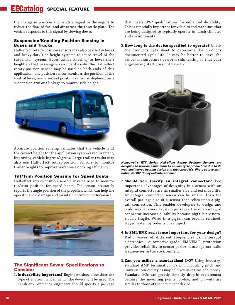
Suspension/Kneeling Position Sensing in Buses and TrucksHall-effect rotary-position sensors may also be used in buses and heavy-duty ride-height systems to sense travel of the suspension system. Buses utilize kneeling to lower their height so that passengers can board easily. The Hall-effect rotary-position sensor may be used on both ends of this application: one position sensor monitors the position of the control lever, and a second position sensor is deployed on a suspension arm or a linkage to monitor ride height.
Accurate position sensing validates that the vehicle is at the correct height for the application system’s requirement, improving vehicle ingress/egress. Large trailer trucks may also use Hall-effect rotary-position sensors to monitor trailer heights to improve warehouse docking efficiency.
Tilt/Trim Position Sensing for Speed BoatsHall-effect rotary-position sensors may be used to monitor tilt/trim position for speed boats. The sensor accurately reports the angle position of the propeller, which can help the operator avoid damage and maintain optimum performance.
The Significant Seven: Specifications to Consider 1. Is durability important? Engineers should consider the
type of environment in which the device will be used. For harsh environments, engineers should specify a package
that meets IP67 qualifications for enhanced durability. This is especially important for vehicles and machines that are being designed to typically operate in harsh climates and environments.
2. How long is the device specified to operate? Check the product’s data sheet to determine the product’s documented cycle life. It may be better to have the sensor manufacturer perform this testing so that your engineering staff does not have to.
3. Should you specify an integral connector? Two important advantages of designing in a sensor with an integral connector are its smaller size and extended life. An integral connected sensor can be smaller than the overall package size of a sensor that relies upon a pig-tail connection. This enables developers to design and build smaller overall system packages. Use of an integral connector increases durability because pigtails are noto-riously fragile. Wires in a pigtail can become strained, frayed, eaten by rodents or crimped.
4. Is EMI/EMC resistance important for your design? Radio waves of different frequencies can interrupt electronics. Automotive-grade EMI/EMC protection provides reliability in sensor performance against radio frequencies in the environment.
5. Can you utilize a standardized I/O? Using industry-standard AMP termination, 32 mm mounting pitch and universal pin-out styles may help you save time and money. Standard I/Os can greatly simplify drop-in replacement because the mounting points, profile, and pin-outs are similar to those of the incumbent device.
Honeywell’s RTY Series Hall-effect Rotary Position Sensors are designed to provide a minimum 15 million cycle product life due to its well-engineered bearing design and the related ICs. Photo source attri-bution:© 2012 Honeywell International
www.eecatalog.com/sensors 11
EECatalog Special Feature
6. How flexible do the sensors for your design need to be? Determine if you are working with one power set-ting or if the sensor should be able to work with a variety of input voltages. It could be beneficial to use position sensors that provide a wide span of operating voltages or ranges. A variety of operating ranges can provide design engineers the resolution needed in the span of travel in many common applications.
7. Is your sensor manufacturer reliable? It is impor-tant to consider whether your supplier can provide the engineering, testing, quality and customization exper-tise you need for your products. Additionally, it can be beneficial if the supplier knows and understands inter-national standards, as well as manufacturing/shipping processes and policies.
Designed to measure, monitor and provide feedback, Hall-effect rotary-position sensors are an integral component in many transportation and industrial applications. Depending on your design application, choosing the right sensor and supplier can be essential to the success of your project.
Chris Gottlieb is Honeywell Sensing and Con-trol ’s senior global product manager for its position solutions product line. She holds a mas-ter’s degree in mechanical engineering from the University of Michigan, Dearborn, and a mas-ter’s degree in business administration from the Ross School of Business at the University of Michigan.
In addition to transportation applications, Hall-effect rotary-position sensors may be used in a wide range of industrial applications.
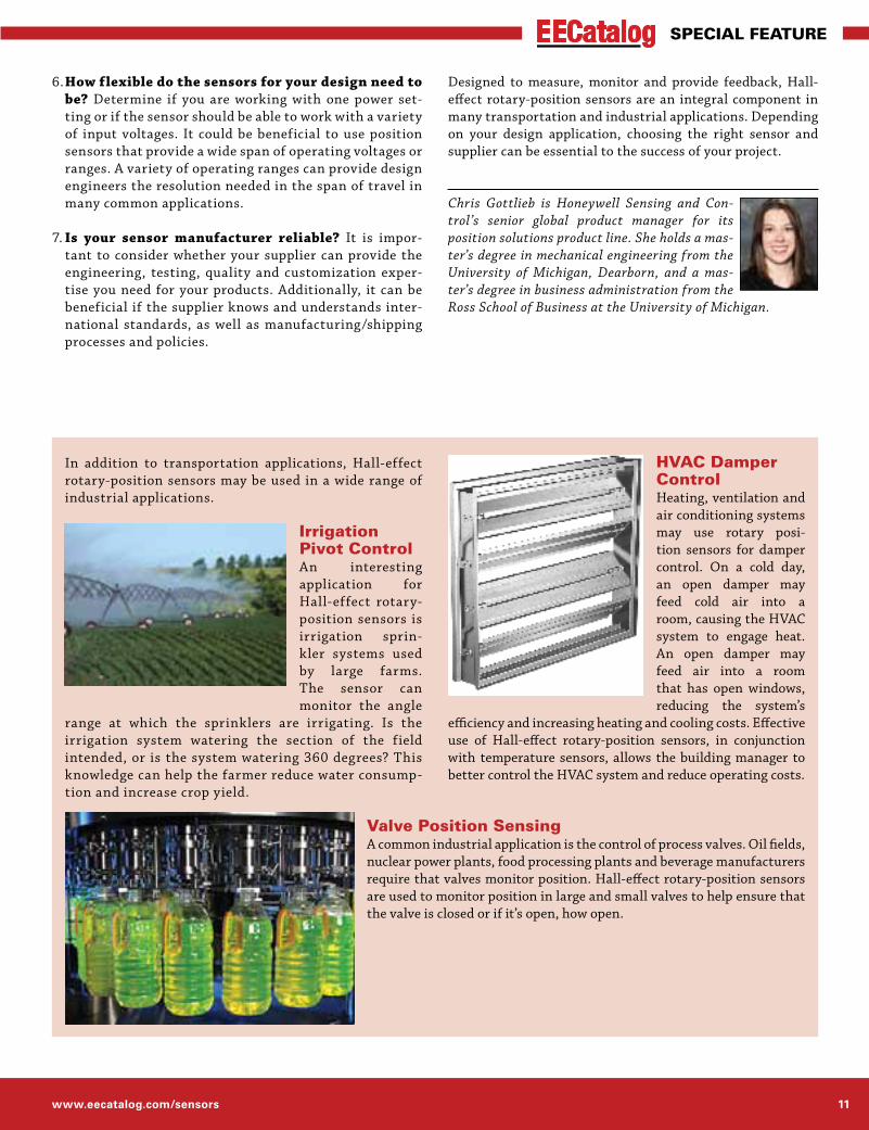
Irrigation Pivot ControlAn interesting application for Hall-effect rotary-position sensors is irrigation sprin-kler systems used by large farms. The sensor can monitor the angle
range at which the sprinklers are irrigating. Is the irrigation system watering the section of the field intended, or is the system watering 360 degrees? This knowledge can help the farmer reduce water consump-tion and increase crop yield.
HVAC Damper ControlHeating, ventilation and air conditioning systems may use rotary posi-tion sensors for damper control. On a cold day, an open damper may feed cold air into a room, causing the HVAC system to engage heat. An open damper may feed air into a room that has open windows, reducing the system’s
efficiency and increasing heating and cooling costs. Effective use of Hall-effect rotary-position sensors, in conjunction with temperature sensors, allows the building manager to better control the HVAC system and reduce operating costs.
Valve Position SensingA common industrial application is the control of process valves. Oil fields, nuclear power plants, food processing plants and beverage manufacturers require that valves monitor position. Hall-effect rotary-position sensors are used to monitor position in large and small valves to help ensure that the valve is closed or if it’s open, how open.

Engineers’ Guide to Sensors & MEMS 201212
EECatalog Special Feature
MEMS integration means different things to different audiences. To pioneers in the MEMS industry, integration may imply a monolithic fabrication process, in which the MEMS and accompanying CMOS electronics are fabricated on the same die. MEMS design automation software sup-pliers have a broader view of integration, one that includes combining MEMS with CMOS electronics, whether in a monolithic process, as separate die in the same package, or even in separate packages. And integration encompasses packaging effects on the MEMS as well. The electronics are analog/mixed-signal (A/MS) circuits that provide electrical input to the MEMS and perform A/D conversion on its output. Such circuits are designed and simulated at a high level of abstraction with tools such as MATLAB and Simulink, and at lower levels of abstraction with EDA soft-ware such as the Cadence Virtuoso suite. MEMS designers, therefore, must deliver models of their designs that are compatible with the tools of choice for electronics design. The integration challenge is a major focus throughout the MEMS ecosystem.
Of course, integration can be a matter of perspective: there are even higher levels of MEMS integration if you view things from a system com-pany’s point of view. To put it simply, one supplier’s system is another’s component. Qualcomm, for example, views the integration challenge from a different perspective. Recently, Len Sheynblat, VP of technology at Qualcomm, spoke at an industry conference about the challenges of integrating sensors into mobile handsets. Today’s smart-phones have as many as 14 sensor types, many of them based on MEMS technology. Sheynblat pointed out there are currently more than 18 sensor vendors offering more than 26 sensor product lines. With no standards for sensor I/O, even across products from the same vendor, the job of selecting and integrating sensors is unnecessarily time consuming. Even the data sheet specs for sensors of the same type are not standardized. The difficulty of sensor selection and integration f lies in the face of increasing pressure on handset makers to bring new generations of handsets to market in ever-shorter cycles (now as short
as six months). In fact, Sheynblat stated that with prices dropping for the sensors themselves, the integration costs comprise a growing proportion of the end-product cost. If sensor integration is challenging for a company with Qual-comm’s technical and financial resources, one can easily imagine that other companies face similar if not greater challenges.
Easier Integration Through StandardsMost industry observers suggest that the way forward is through standardization of hardware and software interfaces. On the hardware side, the system companies would like to see standardization at the digital interface level, such as compatibility with I2C bus. To address this requirement, MEMS-based sensors such as microphones, accelerometers and gyroscopes are increasingly being labeled as digital, meaning they have a digital rather than an analog hardware interface. Thus a MEMS component
may actually be a sub-system that combines a microcon-troller, an A/MS ASIC and the MEMS sensing element in a single package. A 10 degree-of-freedom motion sensor component, for
example, includes a 3-axis accelerometer, 3-axis gyro (usu-ally two or three- separate MEMS), a 3-axis magnetometer (compass) and a barometric pressure sensor, all packaged together with A/MS circuits and a microcontroller. But there are opportunities for standardization of higher-level software layers as well. For instance, combining the output from 10 sensors into the position and orientation information that’s needed by application developers is a nontrivial task that is now handled by “sensor fusion” software. Leading vendors of motion sensors such as ST Microelectronics and InvenSense, as well as a number of software startups, are providing sensor-fusion software to make it easier for application developers to utilize input from motion sensors.
The standardization of software and hardware interfaces to MEMS components will surely happen, either as a result of industry standardization efforts or de facto standards
MEMS Integration Challenges: Today and TomorrowAs MEMS component suppliers compete to offer more functionality in their components, companies will be driven to adopt a MEMS design-automation platform that can most efficiently integrate multiple technologies.
By Dr. Stephen Breit, Coventor, Inc.
To put it simply, one supplier’s system is another’s component.
www.eecatalog.com/sensors 13
EECatalog Special Feature
imposed by a dominant component supplier. At the phys-ical level, perhaps interfacing with I2C bus will become mandatory for market success. At the application level, the programming interfaces to sensor fusion software will no doubt converge. The crucial question, for both system integrators and MEMS component suppliers is: When? The standardization and/or convergence of interfaces will undoubtedly take a number of years. In the interim, both MEMS component suppliers and system integrators will continue to face substantial integration costs, both in engineering effort and time to market.
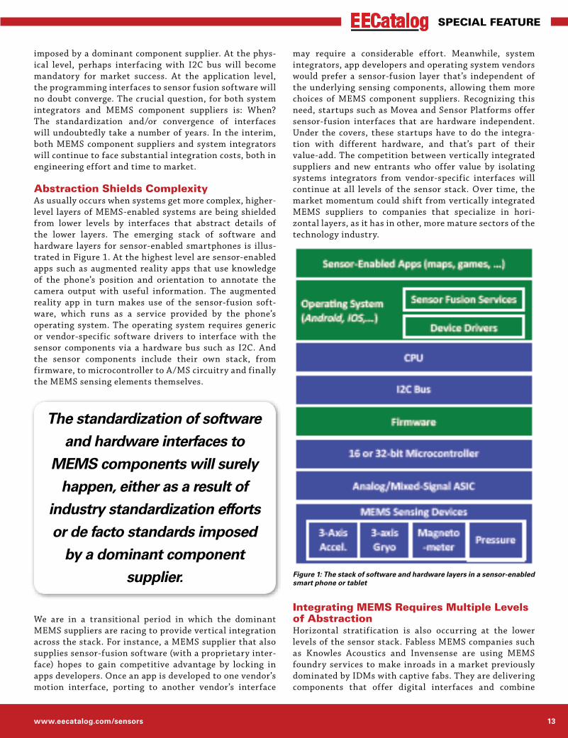
Abstraction Shields ComplexityAs usually occurs when systems get more complex, higher-level layers of MEMS-enabled systems are being shielded from lower levels by interfaces that abstract details of the lower layers. The emerging stack of software and hardware layers for sensor-enabled smartphones is illus-trated in Figure 1. At the highest level are sensor-enabled apps such as augmented reality apps that use knowledge of the phone’s position and orientation to annotate the camera output with useful information. The augmented reality app in turn makes use of the sensor-fusion soft-ware, which runs as a service provided by the phone’s operating system. The operating system requires generic or vendor-specific software drivers to interface with the sensor components via a hardware bus such as I2C. And the sensor components include their own stack, from firmware, to microcontroller to A/MS circuitry and finally the MEMS sensing elements themselves.
We are in a transitional period in which the dominant MEMS suppliers are racing to provide vertical integration across the stack. For instance, a MEMS supplier that also supplies sensor-fusion software (with a proprietary inter-face) hopes to gain competitive advantage by locking in apps developers. Once an app is developed to one vendor’s motion interface, porting to another vendor’s interface
may require a considerable effort. Meanwhile, system integrators, app developers and operating system vendors would prefer a sensor-fusion layer that’s independent of the underlying sensing components, allowing them more choices of MEMS component suppliers. Recognizing this need, startups such as Movea and Sensor Platforms offer sensor-fusion interfaces that are hardware independent. Under the covers, these startups have to do the integra-tion with different hardware, and that’s part of their value-add. The competition between vertically integrated suppliers and new entrants who offer value by isolating systems integrators from vendor-specific interfaces will continue at all levels of the sensor stack. Over time, the market momentum could shift from vertically integrated MEMS suppliers to companies that specialize in hori-zontal layers, as it has in other, more mature sectors of the technology industry.
Integrating MEMS Requires Multiple Levels of AbstractionHorizontal stratification is also occurring at the lower levels of the sensor stack. Fabless MEMS companies such as Knowles Acoustics and Invensense are using MEMS foundry services to make inroads in a market previously dominated by IDMs with captive fabs. They are delivering components that offer digital interfaces and combine
Figure 1: The stack of software and hardware layers in a sensor-enabled smart phone or tablet
The standardization of software and hardware interfaces to
MEMS components will surely happen, either as a result of
industry standardization efforts or de facto standards imposed
by a dominant component supplier.

Engineers’ Guide to Sensors & MEMS 201214
EECatalog Special Feature
ASICS with MEMS sensing elements in a single package. But the race is on to integrate more and more sensing capabilities into the same package. To remain competi-tive, these companies must either develop a full suite of sensors themselves or partner with specialized suppliers of complementary sensors. For example, a company that specializes in MEMS motion sensors (accelerometers and gyros) might partner with a company that specializes in magnetometers. Either way, that word “integration” comes up again. And that’s where MEMS design-automation solu-tions enter the picture.
System architects and ASIC designers who are respon-sible for designing a MEMS component (microcontroller plus ASIC plus multiple MEMS sensing elements) need to work at multiple levels of abstraction. At the highest level of abstraction, the algorithmic level, they’ll likely use MATLAB and Simulink to simulate the sensor(s) in combi-nation with electronics and even digital signal processing. In order to simulate the whole system (again, a component to a handset maker), they’ll need a schematic symbol and underlying model for each MEMS device. At a lower level, the ASIC designers will use EDA tools like Cadence Virtuoso to create and verify a circuit design. They, too, will need a schematic symbol and underlying model to place in their circuit schematic. The design of the MEMS devices themselves will likely remain in the hands of spe-cialists who we call MEMS designers. Those specialists
must hand over models of their MEMS devices that can be simulated in the MATLAB/Simulink and Cadence Virtuoso. Today, the handoff from MEMS designers to system archi-tects and ASIC designers is almost entirely manual. Besides being labor-intensive and a source of human errors, the manu-ally generated MEMS models do not capture all of the physical behavior, leaving the possibility of unexpected interactions between the ASIC and the MEMS that can be dif-ficult to diagnose further down the line.
The challenges of inte-grating ASICs and MEMS
are now being addressed through sophisticated design automation systems, such as the Coventor MEMS+ plat-form, that enable MEMS designers to automatically generate models of their device that run in MATLAB, Simulink or the Virtuoso environment. Ideally, this plat-form would provide automatic links to layout and the ASIC verification f low as well. As demand for MEMS-enabled systems grows, and MEMS component suppliers compete to offer ever more functionality in their components, we anticipate that most MEMS companies will be driven to adopt a MEMS design-automation platform. At the MEMS component level and all higher levels of the sensor stack, the spoils will go to the companies that can most effi-ciently integrate multiple technologies.
Dr. Stephen R. Breit is vice president of engi-neering. He has been responsible for overseeing R&D on all products since joining Coventorin 2000. Prior to that, he was director of embed-ded technology for Dragon Systems and held management positions at Kendall Square Re-search and at BBN Systems and Technologies. Dr. Breit has 25 years of experience in developing technical and scientific applications software. He holds a Ph.D. in engineering from Massachusetts Institute of Technology.
Figure 2: Coventor’s vision for a MEMS design automation platform and MEMS development kits (MDKs) that complement ASIC design tools and methodology

www.eecatalog.com/sensors 15
EECatalog Special Feature
Building on Intel’s Rattner introduction to the future of mobile computing, IMEC’s Liebet Van der Perre recently spoke about the need for ultra-low-power, ultra-high-speed, versatile radios. Dr. Van der Perre is the director of the Green Radios Program at IMEC. What follows is a summary of her presentation.
The prerequisite technology to achieve context-aware mobile computing is improved connected devices—from smartphones and smart buildings to smart devices and displays. This tech-nology is supported by growth numbers, which project that the number of wireless devices will reach beyond 10 billion units in the next few years.
The continued growth in wireless devices brings with it the pre-dictable need for greater bandwidth, connectivity, and mobility. What is far less predictable is the associated user behavior, desired applications, and business models needed to support the market. No one is quite sure what connectivity applications will excite future users. Who could have predicted the rise of Facebook? This is why user-experience-based design has taken on new urgency.
The one certain trend is that all of the technical aspects that support future connectivity will take place in “the cloud”—con-necting machines, users, content providers, governments, and everything imaginable. Dr. Van der Perre highlighted machine-to-machine (M2M) connectivity via the cloud with a picture of a Twittering plant. Using simple electronics and low-power wireless connectivity, the plant tells the farmer when it needs
more or less water. The name of the platform tells it all: Botani-calls (www.botanicalls.com; see Figure 1). I recently covered an unusual Hollywood-style application of low-power, wireless cloud connectivity (see “Embedded World Illuminates TRON,” http://www.entertainmentengineering.com/v8.issue05/18).
In addition to unpredictable user demands and applications, such future connectivity brings enormous technical complexity and uncertainty. The best way to address certain technical crossroads is still being defined in areas ranging from lithog-raphy, EUV, and patterning types to interconnect, air gap, 3D, and packaging issues.
Where is certainty to be found in all of this unpredictability? For wireless devices, the requirements are clear: Decrease power consumption with every increase in performance. But this trad-eoff between power and performance is old news. The one new requirement for future connectivity is the versatility of the radios.
Versatile radios can operate in small heterogeneous cells. Fur-thermore, they can exploit all spectral resources—from today’s crowded 6-GHz ranges to future huge-capacity, unused, and free 60-GHz bandwidths (see Figure 2). The challenge for smaller cells is that they must operate with increasing capacity while radiating less and consuming less energy. Conversely, larger cells will need to achieve greater mobility while increasing transmission coverage areas.
The versatility requirement translates to spectral agility for existing 0-to-6-GHz radios, which now must support 17+ bands for fourth-generation (4G) communications. IMEC has reconfig-urable analog-front-end (Scaldio) and digital-baseband (Cobra) systems-on-a-chip (SoCs) that address these requirements.
It’s one thing to have a sophisticated RF front end to handle 17+ bands. But you also must have an equally versatile antenna interface. Reconfigurable surface-acoustic-wave (SAW) filtering with radio-frequency (RF) microelectromechanical-systems (MEMS) technology provides the most promising answer to the antenna bottleneck issue. RF MEMS also could be tightly integrated within the front-end and baseband chip packages.
In fact, one idea is to integrate the RF MEMS and related pas-sives (like low-loss inductors) into a portion of die-packaging interposer substrate. Using the interposer would provide several benefits, ranging from low-loss antenna filtering to integrated CMOS power amplifiers and low-phase-noise voltage-controlled amplifiers (VCOs).
MEMS and Packaging Hold Keys to Radio ConnectivityBy John Blyler, Editorial Director
Figure 1: One example of machine-to-machine, low-power-radio connectivity via the cloud is provided by Botanicalls.

Engineers’ Guide to Sensors & MEMS 201216
EECatalog Special Feature
RF MEMS also could be used to integrate a switched-capacitor MEMS array within a single software-defined-radio (SDR) package. The MEMS for the array might be located above the integrated circuit (IC) or directly on the interposer.
For the currently uncrowded, free 60-GHz spectrum, versatility will require improved radio platforms to meet the need for cheap, small, and low-power modules for the consumer markets. This means using leading-edge, 40-nm, low-power CMOS processes. Phased-array radio transmitters and receivers will be needed as well as new beamforming functionality. Power consumption must be low: 260 mW for the multiple receivers and 420 mW for the transmitters. Standards bodies have been formed to address this new technology—including a group within the IEEE and the Wireless Gigabit Alliance (WGA).
As always, the big question boils down to balancing perfor-mance (speed) and power. How can we design ultra-high-speed, versatile radios that consume ultra-low power? The good news is that we can. The bad news is that it takes a comprehensive, co-designed approach that requires system, architecture, and technology consideration.
At a system level, the challenge is to move from a performance and coverage mindset to one of capacity and energy. Meeting this challenge will mean connecting via the shortest and best
direct link. Designs will need to enable the versatility to deter-mine—on the fly—what type of link is the best for any given connectivity scenario.
Architecturally, connectivity platforms must be multi-mode and scalable. Improved designs will be needed for the next gen-eration of power-efficient transmitters. Technology will help through further process scaling below 40 nm and with more heterogeneous integration of chip dies and related structures, such as MEMS and interposers.
From a wireless perspective, all of these challenges and solu-tions will welcome a future of very versatile radio devices that can operate at ultra-low power over a variety of heterogeneous networks. These platforms will then provide the technology upon which a sensor-rich, context-aware, user-experience-driven world can exist. Whether it proves to be more beneficial or dis-tracting for most of us remains to be experienced.
John Blyler is the Editorial Director of Extension Media, which publishes Chip Design and Embedded Intel® Solutions magazine, plus over 36 EECatalog Resource Catalogs in vertical market areas.
Figure 2: Future connectivity requires that all spectral resources be exploited—ranging from 0 to 6 GHz and huge bandwidths at around 60 GHz. (Courtesy of IMEC)
www.eecatalog.com/sensors 17
EECatalog Special Feature
MEMS have been in used in automotive, telecommunica-tions, printers, televisions and other applications for some time. Today, the industry is taking MEMS’ low power, low cost and small size and applying them in innovative prod-ucts to leverage their high reliability and high precision attributes – and healthcare is leading the way.
Advanced personal health and medical devices are in high demand. With the Baby Boomer generation, the increase in the elderly population as well as those with chronic illnesses is driving the need for at-home treatment, moni-toring and prevention devices to avoid or limit doctors’ visits and hospital stays. The growing elderly population also has an increasing comfort level with technology, which increases adoption rates. Beyond at-home blood pressure cuffs and other monitoring devices, the introduction of MEMS sensors brings futuristic advancements to meet the population’s need. The ability to quickly detect changes in pressure, location, temperature, speed and other factors is increasing the use of MEMS sensors in personal health and medical devices.
Whether worn or implanted, MEMS sensors are finding their way into a host of healthcare and medical products currently in testing or on the market. Examples include implantable pressure sensors with a wireless antenna to monitor blood pressure from inside blood vessels and report directly to a doctor’s office; rehabilitation and fitness devices with gyroscopes, accelerometers and magnetometers for improved performance analysis during rehabilitation; pres-sure sensors in ophthalmic devices for the detection of glaucoma or macular degeneration; and much more.
MEMS sensors are taking healthcare devices into the future, which is in turn bolstering MEMS market growth. According to iSuppli’s Yole Développement, microsystems for health-
care applications are expected to grow from $1.2 billion in 2009 to $4.5 billion in 2015 with over 1 billion units shipped per year by 2015. And this is just the beginning of the MEMS transformation in the healthcare industry.
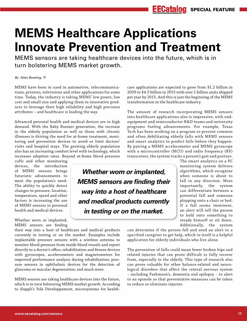
The amount of research incorporating MEMS sensors into healthcare applications also is impressive, with end-equipment and semiconductor R&D teams and university programs fueling advancements. For example, Texas Tech has been working on a program to prevent common and often debilitating elderly falls with MEMS sensors and smart analytics to predict falls before they happen. By pairing a MEMS accelerometer and MEMS gyroscope with a microcontroller (MCU) and radio frequency (RF) transceiver, the system tracks a person’s gait and posture.
The smart analytics on a PC monitoring system delivers algorithms, which recognize when someone is about to fall in any direction. More importantly, the system can differentiate between a potential fall and someone plopping onto a chair or bed. If a fall seems imminent, an alert will tell the person to hold onto something to steady himself or sit down. Additionally, the system
can determine if the person fell and send an alert to a specified caregiver to get help, which in itself is a helpful application for elderly individuals who live alone.
The prevention of falls could mean fewer broken hips and related injuries that can prove difficult to fully recover from, especially in the elderly. This type of research also can prove valuable for other balance-related and neuro-logical disorders that affect the central nervous system – including Parkinson’s, dementia and epilepsy – to alert to an episode so that preventative measures can be taken to reduce or eliminate injuries.
MEMS Healthcare Applications Innovate Prevention and TreatmentMEMS sensors are taking healthcare devices into the future, which is in turn bolstering MEMS market growth.
By Allen Bowling, TI
Whether worn or implanted, MEMS sensors are finding their
way into a host of healthcare and medical products currently
in testing or on the market.

Engineers’ Guide to Sensors & MEMS 201218
EECatalog Special Feature
With the work being done in the MEMS industry on healthcare applications, it is easy to see how tech-nology is advancing to make lives better. With fewer injuries and doc-tor’s visits, shortened hospital stays, more com-fort with fewer wires, needles, poking and prodding, and peace of mind for caregivers who can remotely monitor or be alerted when there is a problem, MEMS sensors are changing our health-care for the better.
R. Allen Bowling, Ph.D. is a TI Fellow and is currently manager of research for TI’s Ana-log Technology Development group in Dallas, Texas. Dr. Bowling serves on several research advisory boards and committees, including the SRC GRC Executive Technical Advisory Board, the Texas Higher Education Coordinating Board Advisory Committee on Research Programs (ACORP), the University of Arizona ESH Research Center Executive Ad-visory Board, the University of Texas at Arlington College of Engineering Board of Advisors, and the University of Texas at Dallas School of Engineering Industrial Advisory Board.
Prototype of wireless fall-pre-vention device using TI’s MSP430 ultra-low power MCU and CC2500 RF transceiver.
Sensors and MEMS OnlInE
Explore...➔ Top Stories and News
➔ White Papers
➔ Expert Opinions (Blogs)
➔ Exclusive Videos
➔ Valuable Articles
➔ Ask the Experts
Sign up for the quarterly Sensors & MEMS E-Product Alert
www.eecatalog.com/sensors

www.eecatalog.com/sensors 19
EECatalog Special Feature
Augmented reality (AR) uses sensor data and embedded vision and graphics processing to synchronize digital information with the physical world in real time. The resulting applications enhance users’ experience of their environment, and enable capabilities that will change the way we interface with and use devices. While AR’s killer app is yet to burst on the scene, we’re already seeing innovative new applications for consumers, healthcare, transporta-tion, industry and defense – and it’s still early yet. But AR presents significant challenges as well as opportunities for developers. We talked to Stephane Gervais-Ducouret, global marketing for sensors at Freescale and Dirk Groten, CTO at Layar to give you an inside look at these exciting new technologies.
EECatalog: Augmented reality has an unquestionable cool factor in consumer mobile applications. What are some of the most interesting new applications for AR and contextual awareness in specialized vertical markets, such as medical, transporta-tion, or defense applications?
Stephane Gervais-Ducouret, Freescale: Defense, and more specifically military aerospace, has success-fully used AR. It is now indispensible: the need for higher speed, increasing f low of
data and the necessity for vital decisions at the right time has pushed the technology to add virtual layers for heads-up displays (HUDs). Even if the biggest buzz is currently around consumer, with applications for smartphones and tablets, the main market that will benefit from AR tech-nology first will be automotive and industrial. This new technology offers more information to the driver, such as driving directions, traffic updates or even an update of yournext meeting, without distracting the driver while driving on the road. With phones being prohibited while driving in some countries, the nascent AR technology will be adopted with specific content displayed on the screen in synchronization with the context (more content
updates during a traffic jam, but minimum content at higher speeds). AR can also enable social networking and conducting office tasks in a car. Industrial markets have applications ranging from learning tools (how to assemble or fix an engine), to support operations (displaying infor-mation for each machine without the need of a dedicated screen) or even product support for business-to-business (recognizing the product and superimposing virtual layers to show how to use a product).
Dirk Groten, Layar: The cool factor in con-sumer applications is very short-lived. Once you’ve seen it and used it for a few minutes, the coolness edges off and most people will be left thinking “now what?” At Layar, we believe AR will become useful, not as a goal
but as a means. And we focus on the consumer market. For example, by making print interactive – not because it’s cool, but because it’s so easy. You look at a page of a maga-zine that has an interesting film review and think, I’d like to see the trailer of that film. Just point your phone at the page and see the movie
trailer appear right there. It’s time the industry takes AR out of the “cool” and into the “utility.”
We don’t focus on the verticals mentioned above as Layar so I believe other companies are more suited to answer the specific question. However, the Dutch Defense has been investigating use of AR (using Layar) in case of big calami-ties during popular events with a large public involved (e.g., open-air concerts, festivals, sports events or exhibitions). They use AR to show the emergency services all relevant locations, including live information about vehicles and team locations (ambulances, fire trucks, crowd control troops, etc.) and at the same created a public version that shows the event information and – in case of emergency – just the emergency exits and arrows for people to follow in case of evacuation.
Digital and Physical Worlds CollideSensor-based augmented reality and contextual awareness are already moving beyond the “cool” factor to drive new, high-utility applications in a wide range of applications. By Cheryl Coupé, Editor
If we cannot address effectively the privacy and security
issues, AR adoption will suffer drastically.

Engineers’ Guide to Sensors & MEMS 201220
EECatalog Special Feature
AR needs to have an obvious utility to the user. It needs to
enrich his life.
EECatalog: What are some of the hardware and software challenges for developers of AR systems?
Gervais-Ducouret, Freescale: Adding virtual layers using markers or location can already be done by using SDKs from companies like Layar. However, developing immersive virtual reality experiences with intuitive access to the information is still challenging. Another challenge is to make sure that the application which has been devel-oped will run smoothly and efficiently on affordable and low-power devices. Hence, usage of processors should be minimized to the benefit of hardware acceleration such as GPUs. Indeed general purpose GPUs are the best hard-ware solution to address the performance requirements in image recognition, embedded vision and graphic inter-faces. OpenGL, OpenCV and OpenCL are some efficient tools; however, there is no framework to encompass these tools to interface them easily with Java and user interface sensors, for instance.
Using information from sensors to gain contextual infor-mation is still in its infancy for developing meaningful applications since it is still not easy to get access from aggregated sensor data.
Groten, Layar: The biggest challenge is to make it so easy to use that everyone (consumer) immediately understands it. That can only happen if the response is near instantaneous so users don’t have to wait to see what will happen. For vision-based AR (recognizing and tracking what’s in the camera view), this requires high processing power and good graphical capabilities. Only this year are we seeing devices (smartphones and tablets) on the market that start to meet the optimal requirements.
For geo-based AR (knowing where the user is and what direction he’s looking at), the problem is still the preci-sion: GPS position and compass direction are still quite inaccurate to convey a real AR experience and probably only vision-aided AR, where buildings and other parts of the public space are recognized and tracked, will give the real experience.
In both cases you need a network connection to send video information to be recognized from a large database (as you can’t possibly cache the entire world locally in the phone) or pre-fetch local information. That network (wireless) connection is always going to be a bottleneck in getting a smooth experience.
EECatalog: How are developers addressing security and privacy issues related to AR?
Gervais-Ducouret, Freescale: If we cannot address effec-tively the privacy and security issues, AR adoption will suffer drastically. Indeed, the developers must provide an easy way for the user to control the information he is sharing. A common interface should become a standard for the industry to avoid confusion and to make sure that privacy is regarded with the same importance by the device manufacturer and developer. Security is crucial for automo-tive and industrial markets. For instance, the driver of the vehicle should be recognized before displaying information which can be disturbing for some people and necessary for others. But I do not believe that we should put in place a specific driving license to handle AR while driving.
Groten, Layar: I don’t think AR has any other security or privacy issues than any other application. There is some unchartered (legal) territory in AR, for example about who owns the space on which augmented reality is added. For example, would it be acceptable if people start adding “I love Pepsi” virtual stickers onto every Coca-Cola can or ad? (This can be done today with an application like Stiktu, that lets people add AR to any image just using the mobile phone.) We strongly believe that public space belongs to the public and AR gives people the possibility to reclaim
the space (albeit virtually) the way they want it.
But if there’s a social com-ponent to an AR application, the same privacy and secu-rity concerns apply as to any social application (Facebook) and if there’s a location-
based component to an AR application, the same privacy concerns apply as to any location-based application (Four-square).
EECatalog: How will AR applications and sensor tech-nologies drive new user interfaces?
Gervais-Ducouret, Freescale: AR technology success will depend on how developers embrace sensors for context awareness and user interfaces. This is already the case in some applications since sensors such as accelerometers, magnetometers and gyroscopes are used to match the position of the mobile device with its environment to virtually add adequate information. With the number of recognized objects increasing, accurate pointing using sensor fusion is becoming necessary. However, much more should be done to provide the user a long-term adoption of AR applications; for instance, the localization must be ready prior to any request from the user, hence, only the combination of inertial sensors with WiFi or GPS can provide the low power of continuous position tracking. Another improvement is pattern recognition of acceler-ometer data, which can provide information about what the user is intending, thus, starting the right application
www.eecatalog.com/sensors 21
EECatalog Special Feature
and preparing the data (avoiding the user to having to look at menus). Accelerometers and gyroscopes should also be used to improve camera tracking with recognized objects and efficiently add virtual information in a seamless way. Conducting gesture recognition is an example.
Groten, Layar: That’s an interesting question. Because right now, AR is mostly used on smartphones and that is an entire different user interface than if it were to be used with AR glasses. With smartphones, I think we will see more and more the “point to view” paradigm, where users can just point their phone at something to view more content. With glasses the challenge is of course the user control. Voice-control like Google showed with the Google Glass project is the most obvious option, but in general voice control still is in its infancy (even though Google Voice and Apple’s Siri show some progress) and only covers a small part of the richness of current touch-based user interfaces.
EECatalog: What advances need to occur in today’s avail-able technologies for AR to reach critical mass?
Gervais-Ducouret, Freescale: AR’s key value is the intui-tive display of information that matches our environment. Hence, AR needs to select the appropriate information and display it with virtual layers using our location and our context. One of the first technology improvements is to address the localization, and especially in-door positioning, by mastering the aggregation of multiple technologies: GPS, cell ID, WiFi positioning and sensor fusion. Secondly, context awareness technology should greatly involve various sensors to guess what the user wishes to do by understanding who, what and when. This
is surely one of the major fields of innovation. Thirdly, applications and SDKs should heavily use hardware-accelerated software running on GPUs to allow fast image processing and great graphic display for immersive virtual reality experiences. Lastly, the user interface must become fully intuitive by using sensor fusion for gesture recogni-tion, navigation and accurate pointing to “add sensing to our vision.”
Groten, Layar: Not much: AR needs to have an obvious utility to the user. It needs to enrich his life. Otherwise it’ll remain a gimmick, a cool game that you play for an hour or a one-time “wow” experience. It doesn’t have to look fancy or be immersive; it just needs to make sense. For example, with Stiktu, anyone can annotate any real object or image and share it with friends. Anyone else pointing their phone at the same object will see the annotation and be able to annotate it as well, creating a conversation on top of things. Or with Layar, any magazine, newspaper or billboard creator can add a digital layer on top of their print creating interaction with the reader.
Cheryl Berglund Coupé is editor of EECatalog.com. Her articles have appeared in EE Times, Elec-tronic Business, Microsoft Embedded Review and Windows Developer’s Journal and she has devel-oped presentations for the Embedded Systems Conference and ICSPAT. She has held a variety of production, technical marketing and writing positions within technology companies and agencies in the Northwest.
Engineers’ Guide to Sensors & MEMS 201222
EECatalog Special Feature
For the first part of the 20th century, mechanical engi-neering dominated almost everything in technology. For the second half, once the transistor and the integrated cir-cuit became well entrenched, those two disciplines largely divided up the tech market.
More recently, however, they are being forced to collaborate in teams that historically had nothing in common. While the combination of electrical engineering with software has raised questions about how to trade information back and forth, mechanical and electrical engineering arguably are even further apart. But there is at least one consistent element throughout the most recent combination—power.
Power and HeatOne of the biggest changes in engineering is that power is global. Physical effects such as heat, electrostatic dis-charge and leakage current can affect many other levels of a much larger system. That larger system could be a car, an airplane, or a data center.
“Inside of an engineering organization, someone near the top has to worry about the entire system,” said Larry Williams, director of product management for the elec-tronics business unit of Ansys. “They have to think about boundaries between systems and subsystems, or between mechanical engineering and electrical engineering, because many firms are organized that way. When building a system, the optimum design can be found by considering the system as a whole, and additional margin is often found at those boundaries.”
He said that at a meeting within one defense contractor, he actually introduced the mechanical and electrical engineering teams, who had never met even though they worked on the same projects. Those silos have since begun breaking down, in part because systems demand power efficiency, better reliability and lower cost. Things that used to be done as purely mechanical engineering may be mixed together as part of a bigger system.
But the perspective of each is different. Consider thermal budgets, for example. Electrical engineers focus on turning off as much of a chip as possible when it’s not in use, and running what’s in use as efficiently as possible—even going so far as to weigh whether specific operations use less energy when they’re run at maximum speed for
short periods of time or slower speeds over longer periods of time. Mechanical engineers, meanwhile, focus in the other direction—cooling the devices as close to the heat generation as possible. In the past, that meant simply drilling holes into metal and adding heat sinks and fans.
“As density has increased it is no longer possible to thermally manage a device around the PCB,” said Robin Bornoff, FloTherm product marketing manager in Mentor Graphics’ Mechanical Analysis Division. “It’s gotten to the point where the mechanical perspective cannot be a sepa-rate discipline. We’re now seeing representatives of the thermal design teams showing up right from the begin-ning in meetings with the system architect. They have to work together.”
That discussion becomes even more critical in 3D stacking, where heat can get trapped between two die. And it’s not just the stacked die that needs to be considered. It’s what’s around it, as well.
“Heat doesn’t obey existing design discipline barriers,” said Bornoff. “The heat will spread into the air, the chassis, the
Mechanical Meets ElectricalThe two engineering worlds intersect – driven by power, heat and signal integrity.By Ed Sperling, Contributing Editor
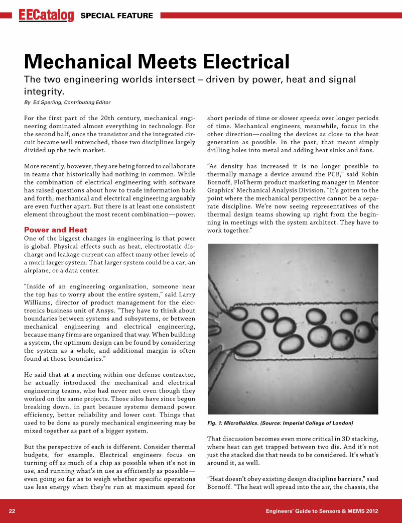
Fig. 1: Microfluidics. (Source: Imperial College of London)
www.eecatalog.com/sensors 23
Special feature
room, and out from there. How hot the silicon gets affects everything, sometimes even outside the building. That’s why you’re starting to see water-cooling in space applica-tions and in data centers. It’s 1,000 times denser than air and 1,000 times better at removing heat.”
The challenge is to get that cooling as close to the source of heat as possible. So rather than just cooling a server cabinet, for example, the liquid is pumped around the pro-cessors producing the heat. There is even research under way in microfluidics to pump liquid around the chip itself in a stacked die. Bornoff noted that initial approaches tried to squeeze the f luid through very narrow channels, which required massive pressure. He said the latest research uses piezoelectric fans and pumps, whereby vibration creates movement in the f luid.
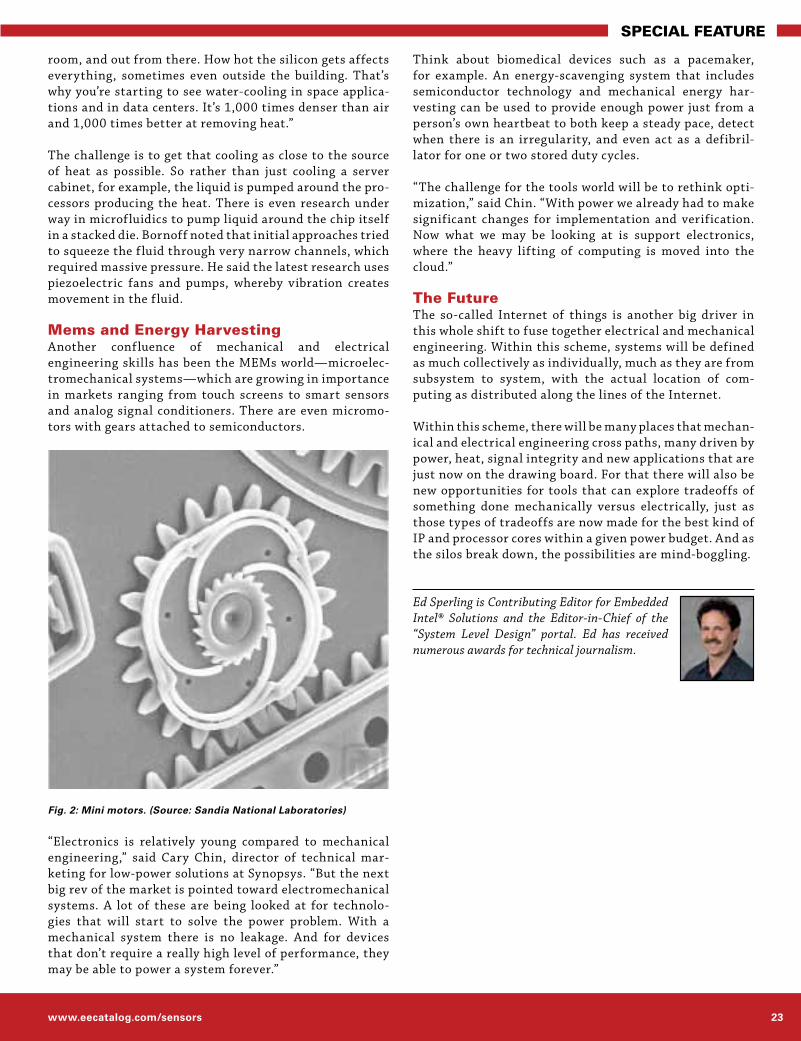
Mems and Energy HarvestingAnother confluence of mechanical and electrical engineering skills has been the MEMs world—microelec-tromechanical systems—which are growing in importance in markets ranging from touch screens to smart sensors and analog signal conditioners. There are even micromo-tors with gears attached to semiconductors.
“Electronics is relatively young compared to mechanical engineering,” said Cary Chin, director of technical mar-keting for low-power solutions at Synopsys. “But the next big rev of the market is pointed toward electromechanical systems. A lot of these are being looked at for technolo-gies that will start to solve the power problem. With a mechanical system there is no leakage. And for devices that don’t require a really high level of performance, they may be able to power a system forever.”
Think about biomedical devices such as a pacemaker, for example. An energy-scavenging system that includes semiconductor technology and mechanical energy har-vesting can be used to provide enough power just from a person’s own heartbeat to both keep a steady pace, detect when there is an irregularity, and even act as a defibril-lator for one or two stored duty cycles.
“The challenge for the tools world will be to rethink opti-mization,” said Chin. “With power we already had to make significant changes for implementation and verification. Now what we may be looking at is support electronics, where the heavy lifting of computing is moved into the cloud.”
The FutureThe so-called Internet of things is another big driver in this whole shift to fuse together electrical and mechanical engineering. Within this scheme, systems will be defined as much collectively as individually, much as they are from subsystem to system, with the actual location of com-puting as distributed along the lines of the Internet.
Within this scheme, there will be many places that mechan-ical and electrical engineering cross paths, many driven by power, heat, signal integrity and new applications that are just now on the drawing board. For that there will also be new opportunities for tools that can explore tradeoffs of something done mechanically versus electrically, just as those types of tradeoffs are now made for the best kind of IP and processor cores within a given power budget. And as the silos break down, the possibilities are mind-boggling.
Ed Sperling is Contributing Editor for Embedded Intel® Solutions and the Editor-in-Chief of the “System Level Design” portal. Ed has received numerous awards for technical journalism.
Fig. 2: Mini motors. (Source: Sandia National Laboratories)

Engineers’ Guide to Sensors & MEMS 201224
EECatalog Special Feature
Though MEMS (micro-electromechanical systems) tech-nology has been on the job for about two decades in airbag deployment and automotive pressure sensors, it took the motion-sensing user interfaces featured in video games and smart phones to catapult broad awareness of what inertial MEMS sensors can do.
Still, to an extent the idea persists that inertial sensors are useful mainly when the end product has a need to detect acceleration and deceleration. True enough from a purely scientific view. Yet, that could be to miss out on many of the expanding uses of MEMS accelerometers and gyroscopes in areas such as medical devices,industrial equipment, con-sumer electronics, and automotive electronics.
Looking at what becomes possible in each of the five modes of motion sensing vastly expands the options beyond today’s high volume MEMS applica-tions. These five modes are acceleration (including translational movement such as position and orientation), vibra-tion, shock, tilt, and rotation.
Introduction to Motion Sensing and MEMSAcceleration, vibration, shock, tilt, and rotation—all except rotation are actually different manifestations of acceleration over different periods of time. However, as humans we don’t intuitively relate to these motion senses as variations on acceleration/decelera-tion. Considering each mode separately helps in envisioning more possibilities.
Acceleration (remember, including translational movement) measures the change in velocity in a unit of time. Velocity is expressed in meters per second (m/s) and includes both the rate of displacement and direction of move-ment. It follows that acceleration is
measured in meters per second squared (m/s2). Acceleration with a negative value – imagine a car slowing down when the driver applies the brakes – is known as deceleration.
Now consider acceleration over various periods of time. Vibration can bethought of as acceleration and decelera-tion that happens quickly and in a periodic manner.
Similarly, shock is acceleration that occurs instanta-neously. But unlike vibration, a shock is a non-periodic function that typically happens once.
Let’s stretch out the length of time again. When an object is moved to alter its tilt, or inclination, some change in position with respect to gravity is involved. That move-
MEMS Inertial Sensing: The Five Motion SensesWhether the need is for user-friendly features, minimizing power consumption, eliminating physical buttons and controls, compensating for gravity and position or more intelligent operation, MEMS-based inertial sensing offers an abundance of options to explore across all five motion senses. By Rob O’Reilly and Harvey Weinberg, Analog Devices
Figure 1: The five motion senses: acceleration, vibration, shock, tilt and rotation
First there was analog audio and video signal processing. Now there’s MEMS motion signal processing–an enabler that will soon make all kinds of functions possible.

www.eecatalog.com/sensors 25
EECatalog Special Feature
ment tends to happen rather slowly compared with vibration and shock.
Because these first four modes of motion sensing each involve a certain aspect of acceleration, they are mea-sured by g-force, the unit of force that gravity exerts on an object on the Earth. (One g equals 9.8 m/s2.) A MEMS accelerometer detects tilt by measuring the effect the force of gravity exerts on the axes of the accelerometer. In the instance of a3-axis accelerometer, three separate outputs measure acceleration along the X, Y, and Z axes of motion.
The accelerometers with the largest share of the market today use differential capacitors to measure g-force, which is then converted into volts or bits (in the case of digital output accelerometers) and then passed to a micropro-cessor to perform an action. Recent advances in technology have made it possible to manufacture tiny MEMS accel-erometers in low-g and high-g sensing ranges with much wider bandwidth than previously, greatly increasing the field of potential applications. A low-g sensing range is less than 20 g and deals with motion a human can generate. High-g is useful for sensing motion related to machines or vehicles—in essence, motion that humans cannot create.
So far we have discussed only linear rate motion, the type of motion that includes acceleration, vibration, shock, and tilt. Rotation is a measure of angular rate motion. This mode differs from the others because rotation may take place without a change in acceleration. To understand how that works, picture a 3-axis inertial sensor. Say that the sensor’s X and Y axes are parallel to the Earth’s surface; the Z axis is pointing toward the center of the Earth. In this position, the Z axis measures 1 g; the X and Y axes register 0 g. Now rotate the sensor to move only about the Z axis. The X and Y planes simply rotate, continuing to measure 0 g while the Z axis still measures 1 g.
MEMS gyroscopes are used to sense this rotational motion. Because certain end products must measure rota-tion in addition to other forms of motion, gyroscopes may be integrated in an IMU (inertial measurement unit) that embeds a multiaxis gyroscope and multiaxis accelerom-eter.
Acceleration in Usability and Power ManagementAcceleration also comes into play for detecting movement and position. This creates the possibility of using a MEMS accelerometer to notice when a device is picked up and put down,which when detected can generate an interrupt that powers functions on and off automatically. Various combinations of functions can be kept active or put into the lowest power state possible. Movement-driven on/off features are human-friendly because they eliminate repetitive actions on the user’s part. What’s more, they enable power management that lets the device go longer
between recharging or replacing the battery. An intelligent remote control with a backlit LCD is among the potential scenarios.
Another application for movement sensing is in medical equipment such as automated external defibrillators. Typically, AEDs have been designed to deliver a shock that gets the patient’s heart pumping again. When that fails, manual cardiopulmonary resuscitation must be per-formed. A less experienced rescuer might not compress the patient’s chest enough for effective CPR. Accelerometers embedded in the AED’s chest pads can be used to give the rescuer feedback on the proper amount of compression by measuring the distance the pad is moved.
Vibration for Monitoring and Energy SavingSlight changes in vibration serve as a leading indicator of worn bearings, misaligned mechanical components and other issues in machinery, including industrial equip-ment. Very small MEMS accelerometers with very wide bandwidth are ideal for monitoring vibration in motors, fans, and compressors. Being able to perform predictive maintenance lets manufacturing companies avoid damage to expensive equipment and prevent breakdowns that cause costly productivity loss.
Measuring changes in the equipment’s vibration signature could also be used to detect whether machinery is tuned to operate in an energy-efficient manner. Unless corrected, this inefficient operation could hurt a company’s green
Figure 2: Acceleration example, sensing of movement and position: The PocketCPR
The PocketCPR device is used to assist a rescuer in the delivery of high-quality CPR chest compressions. An ADI MEMS accelerometer provides the crucial sensor function to measure the depth and rate of chest wall movement during each compression, a critical element for reliable real-time performance during CPR.

Engineers’ Guide to Sensors & MEMS 201226
EECatalog Special Feature
manufacturing effort and drive up its electricity bills or eventually lead to damaged equipment as well.
Shock, Gesture Recognition and MoreThe disk drive protection found in many notebook PCs is a widely implemented application of shock sensing. An accelerometer detects tiny g-forces that indicate the note-book is falling or dropping, which is a precursor to a shock event: hitting the f loor. Within milliseconds,the system orders the hard disk drive head to be parked. Parking the head stops contact with the disk platter during impact, preventing damage to the drive and the resulting data loss.
Gesture recognition interfaces are a promising new use for this type of inertial sensing. Defined gestures, such as taps, double-taps, or shakes, allow users to activate dif-ferent features or adjust the mode of operation. Gesture recognition makes devices more usable where physical buttons and switches would be difficult to manipulate. Button-free designs can also reduce overall system cost in
addition to improving the durability of end products such as underwater cameras, where the opening surrounding a button would let water seep into the camera body.
Tilt Sensing for Precision OperationTilt sensing has tremendous potential in gesture recogni-tion interfaces as well. For instance, one-handed operation may be preferable in applications such as construction or industrial inspection equipment. The hand not operating the device remains free to control the bucket or platform where the operator stands, or perhaps to hold a tether for safety’s sake. The operator could simply “rotate” the probe or device to adjust its settings. A 3-axis accelerometer would sense the “rotation” as tilt in this case: measuring low speed changes in inclination in the presence of
Figure 3: Vibration example: machine health and bearing wear
Vibration in rotating machinery typically occurs at frequencies from 6 to 10 KHz. Vibration sensing using MEMS accelerometers is becoming an important alternative to conventional sensing approaches, as the demand for earlier and less costly predictive maintenance alternatives increases.
Figure 4: Shock example, IBM ThinkPad® notebook automatic hard drive protection
IBM’s ThinkPad® notebook computers offered the first automatic hard drive protection technology of its kind using airbag-like MEMS crash sensors from ADI. Sudden acceleration in the notebook’s motion triggers a signal to park the read/write head within 500 milliseconds before the notebook actually hits the floor.
Figure 5: Tilt sensing example, Omron Wrist blood pressure monitor with advanced positioning sensor
ADI’s MEMS accelerometer enables precise tilt inclination measurement of the user’s forearm so when the blood pressure monitoris located correctly at heart level the cuff starts to inflate for more accurate blood pressure measurement through cuff position sensing.

www.eecatalog.com/sensors 27
EECatalog Special Feature
gravity, detecting the change in the gravity vector, and determining whether the direction is clockwise or coun-terclockwise. Tilt detection could also be combined with tap (shock) recognition to let the operator control more functions of the device single-handedly.
Compensating for the position of a device is another sig-nificant area where tilt measurement is useful. Take the electronic compass in a GPS (global positioning system) or mobile handset. A well-known problem here is the heading error that results when the compass is not positioned exactly parallel to the surface of the Earth.
Rotation: Gyroscopes and IMUs in ActionAs already noted, real-world applications of MEMS tech-nology can benefit when rotation is combined with other
forms of inertial sensing. In practice this calls for using an accelerometer as well as a gyro-scope. Inertial measurement units have been introduced that include a multiaxis accelerom-eter, a multiaxis gyroscope, and—to increase heading accuracy further—a multiaxis mag-netometer. The IMU may, in addition, provide a full 6 degrees of freedom (6 DoF). This brings ultra fine resolution to applications such as medical imaging equipment, surgical instrumentation, advanced prosthetics, and automated guidance for industrial vehicles. Besides highly precise operation, another advantage of selecting an IMU is that its multiple functions can be pretested and preca-librated by the sensor’s manufacturer.
The New Wave of Motion Signal ProcessingWhether the need is for user-friendly features, minimizing power consumption, eliminating physical buttons and controls, compensating for gravity and position or more intelligent operation, MEMS-based inertial sensing offers an abundance of options to explore across all five motion senses. In the next wave of MEMS sensor adoption, sensor fusion will become a key function in many existing and emerging applications. And it’s not just an integration proposition, but it’s about using the redun-dancy of multiple sensor types to improve accuracy and precision in the application.
Rob O’Reilly joined Analog De-vices in the very early days of MEMS and has spent the last 17 years creating test and char-acterization capabilities for MEMS accelerometers, gyros and optical devices. A former flight engineer in the US Navy, Rob at-tended Northeastern University with focus in the area of shock and vibration analysis. Harvey Weinberg is an applications engineer-ing manager for Analog Devices’ Automotive Segment Group. He has over 20 years system and circuit design experience and holds a BSEE degree.
Figure 6: Rotation/Gyroscope example: Anybots’ QB telepresence robot
Like the Segway, the Anybots QB telepresence robot uses ADI’s multi-axis MEMS motion sensing technology for navigation, platform stabilization, and as a control system to help it process the operator’s directional commands and remain upright even when bending.
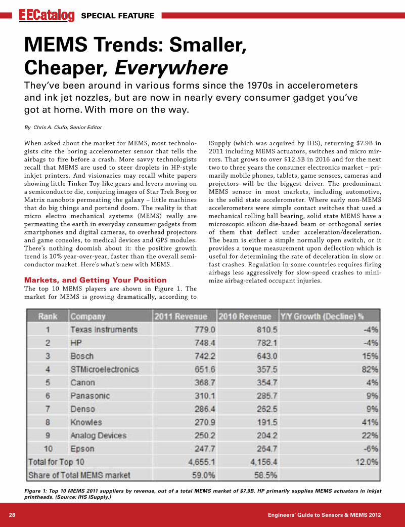
Engineers’ Guide to Sensors & MEMS 201228
EECatalog Special Feature
When asked about the market for MEMS, most technolo-gists cite the boring accelerometer sensor that tells the airbags to fire before a crash. More savvy technologists recall that MEMS are used to steer droplets in HP-style inkjet printers. And visionaries may recall white papers showing little Tinker Toy-like gears and levers moving on a semiconductor die, conjuring images of Star Trek Borg or Matrix nanobots permeating the galaxy – little machines that do big things and portend doom. The reality is that micro electro mechanical systems (MEMS) really are permeating the earth in everyday consumer gadgets from smartphones and digital cameras, to overhead projectors and game consoles, to medical devices and GPS modules. There’s nothing doomish about it: the positive growth trend is 10% year-over-year, faster than the overall semi-conductor market. Here’s what’s new with MEMS.
Markets, and Getting Your PositionThe top 10 MEMS players are shown in Figure 1. The market for MEMS is growing dramatically, according to
iSupply (which was acquired by IHS), returning $7.9B in 2011 including MEMS actuators, switches and micro mir-rors. That grows to over $12.5B in 2016 and for the next two to three years the consumer electronics market – pri-marily mobile phones, tablets, game sensors, cameras and projectors–will be the biggest driver. The predominant MEMS sensor in most markets, including automotive, is the solid state accelerometer. Where early non-MEMS accelerometers were simple contact switches that used a mechanical rolling ball bearing, solid state MEMS have a microscopic silicon die-based beam or orthogonal series of them that deflect under acceleration/deceleration. The beam is either a simple normally open switch, or it provides a torque measurement upon deflection which is useful for determining the rate of deceleration in slow or fast crashes. Regulation in some countries requires firing airbags less aggressively for slow-speed crashes to mini-mize airbag-related occupant injuries.
MEMS Trends: Smaller, Cheaper, EverywhereThey’ve been around in various forms since the 1970s in accelerometers and ink jet nozzles, but are now in nearly every consumer gadget you’ve got at home. With more on the way.
By Chris A. Ciufo, Senior Editor
Figure 1: Top 10 MEMS 2011 suppliers by revenue, out of a total MEMS market of $7.9B. HP primarily supplies MEMS actuators in inkjet printheads. (Source: IHS iSupply.)

www.eecatalog.com/sensors 29
EECatalog Special Feature
The largest accelerometer suppliers are Bosch GmbH, which grew MEMS shipments 15 percent to $742.2M in 2011, and STMicroelectronics which shipped more than $650M of MEMS in 2011 (up 82 percent); STMicro ships 50 percent of the world ’s MEMS accelerometers for handsets, tablets, laptops and gaming. But beyond auto-motive, accelerometers are the devices that orient the screen from portrait to landscape on mobile phones like the iPhone or tablets like the iPad. MEMS are also used in the Nintendo Wii ’s Remote and Sony’s PS3 remote, where accelerometers are coupled with MEMS single- or three-axis gyroscopes to provide reference to the ground for “steering” motion. In fact, according to iSupply, gyro-scopes represent 55 percent of STMicro’s sales growth as “the golden age for consumer accelerometers” wanes, says iSupply’s Jeremie Bouchard, director and senior principal analyst for MEMS and sensors. Still, 40 percent of all mobile phones use MEMS accelerometers.
But add in a MEMS gyro, and cool things can happen in your consumer device. Not only can you orient the device relative to the ground or magnetic north (yes, there are MEMS compasses), but the rate of movement can be measured and provide more finely grained relative posi-tions in three-space. If an Android phone is to replace a high-end Sony Vita game console, more precise motions and angular acceleration need to be detected. Accelerom-eter plus gyro plus compass equals very accurate motion movements and position orientation.
According to Chipworks MEMS sector analyst St. J. Dixon-Warren, “the iPhone 4 is the first portable device to feature full nine degree-of-freedom inertial sensing.” After a com-plete tear-down, Chipworks discovered that the phone uses an STMicro three-axis accelerometer, an AKM three-axis electronic compass, and an STMicro three-axis gyro. The accelerometer, shown in Figure 2, utilizes “interdigitated” finger capacitors for XY, offset with a vertical deflection mass on a MEMS torsion spring that changes capacitance when moved in the Z direction. The packaged gyro is an ASIC plus MEMS stacked die, where the MEMS sensor uses tuning fork mass structures to measure pitch, roll and yaw (Figure 3). An isometric view of the gyro shown in Figure 4 clearly shows the mechanical nature of the die. Lastly, the electronic compass, says Chipworks, is the same as the iPhone 3GS and uses four Hall effect sensors surrounding a metal solenoid coil (Figure 5).
With all three MEMS sensor devices aboard, the iPhone 4 has unheard-of accuracy for navigation, in-hand gesture recognition (think Microsoft Kinect spatial knowledge, but holding the device itself ), and dead-reckoning ori-entation. Couple these with the consumer-grade GPS accuracy already in the device, and indoor navigation becomes a reality. Who cares about that? First-responders such as police and fire fighters could navigate in dark or smoky buildings, or consumers could precisely find their
way to an exact shelf in a grocery store. Future MEMS pressure sensors will act as altimeters, providing vertical navigation up and down buildings, caves, or mountains when GPS is inaccessible.
Figure 2: STMicroelectronics’ 3-axis accelerometer is used in Apple’s iPhone 4s, as discovered by Chipworks. 3-axis isn’t very common yet. (Courtesy: Chipworks.)
Figure 3: A 3-axis MEMS gyro is used in the iPhone 4s. The gyro resolves pitch, roll, and yaw when coupled with an ASIC stacked die. (Courtesy: Chipworks.)
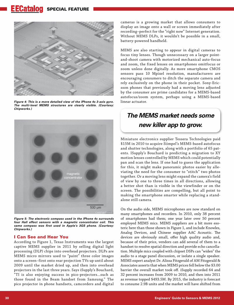
Engineers’ Guide to Sensors & MEMS 201230
EECatalog Special Feature
I Can See and Hear YouAccording to Figure 1, Texas Instruments was the largest captive MEMS supplier in 2011 by selling digital light processing (DLP) chips into overhead projectors. DLPs are MEMS micro mirrors used to “paint” three color images onto a screen–first onto rear projection TVs up until about 2009 until the market dried up, and then into overhead projectors in the last three years. Says iSupply’s Bouchard, “TI is also enjoying success in pico-projectors...such as those found in the Beam handset from Samsung.” The pico projector in phone handsets, camcorders and digital
cameras is a growing market that allows consumers to display an image onto a wall or screen immediately after recording–perfect for the “right now” Internet generation. Without MEMS DLPs, it wouldn’t be possible in a small, battery-powered handheld.
MEMS are also starting to appear in digital cameras to focus tiny lenses. Though unnecessary on a larger point-and-shoot camera with motorized mechanical auto-focus and zoom, the fixed lenses on smartphones omitfocus or zoom unless done digitally. As more smartphone CMOS sensors pass 10 Mpixel resolution, manufacturers are encouraging consumers to ditch the separate camera and rely exclusively on the phone in their pocket. Sony-Eric-sson phones that previously had a moving lens adjusted by the consumer are prime candidates for a MEMS-based autofocus/zoom system, perhaps using a MEMS-based linear actuator.
Miniature electronics supplier Tessera Technologies paid $15M in 2010 to acquire Siimpel’s MEMS-based autofocus and shutter technologies, along with a portfolio of 65 pat-ents. ISupply’s Bouchard is predicting a migration to XY motion lenses controlled by MEMS which could potentially pan and scan the lens. If one had to guess the application for this, it might make panoramic photos easier by alle-viating the need for the consumer to “stitch” two photos together. Or a moving lens might expand the camera’s field of view by one to three times in all directions, allowing a better shot than is visible in the viewfinder or on the screen. The possibilities are compelling, but all point to making the smartphone smarter while replacing a stand-alone still camera.
On the audio side, MEMS microphones are now standard on many smartphones and recorders. In 2010, only 38 percent of smartphones had them; one year later over 50 percent employed MEMS mics. MEMS suppliers are a bit more eso-teric here than those shown in Figure 1, and include Knowles, Analog Devices, and Chinese supplier AAC Acoustic. The devices are obviously small, offer high quality audio and, because of their price, vendors can add several of them to a handset to resolve spatial direction and provide echo cancella-tion. Multiple mics coupled with chipset DSPs can “widen” the audio to a stage panel discussion, or isolate a single speaker. MEMS expert analyst Dr. Alissa Fitzgerald of AM Fitzgerald & Associates asserts that when MEMS prices fell below the $3.00 barrier the overall market took off. iSupply recorded 64 and 32 percent increases from 2009 to 2010, and then into 2011 as revenue topped $493.5M. By 2015, the industry is forecast to consume 2.9B units and the market will have shifted from
Figure 4: This is a more detailed view of the iPhone 4s 3-axis gyro. The multi-level MEMS structures are clearly visible. (Courtesy: Chipworks.)
Figure 5: The electronic compass used in the iPhone 4s surrounds four Hall effect sensors with a magnetic concentrator coil. This same compass was first used in Apple’s 3GS phone. (Courtesy: Chipworks.)
The MEMS market needs some new killer app to grow.

www.eecatalog.com/sensors 31
EECatalog Special Feature
analog MEMS microphones to digital ones like those found in Apple’s iPad and iPad 2. Digital microphones don’t require external passives, have higher audio quality and are more EMI resistant.
Future TrendsAs the “Internet of things” connects everyone and every-thing, mobile intelligence, M2M connectivity and carrying your entire life in your pocket all portend good things for MEMS sensors. New pressure sensors from Bosch act as altimeters that provide height information. Start-up com-pany InvenSense introduced in 2011 its 6-axis MotionFusion 3-axis gyroscope and accelerometer optimized for use with 8-bit (read: low cost) MCUs; Atmel immediately added the product to the AVR Studio MCU development tool suite.
And it’s only a matter of time before the MEMS device is resi-dent monolithically on the same die with digital logic, further wringing cost and footprint out of size-constrained consumer platforms like smartphones. “Start-up” company WiSpry spent 11 years perfecting its tunable MEMS capacitor (Figure 6) that can change capacitance by up to 20x and when ganged together on-chip offers 1/8, 1/4, and 1/2 pF increments. When coupled with digital controller on the die (Figure 7), the device can digitally “tune” a smartphone’s antenna impedance to match a power amplifier’s characteristics. Remember the problems with Apple’s iPhone 4 “Antenna-Gate” when one’s hand covered the lower part of the phone’s body and inadvertently changed the case-mounted antenna’s impedance? Problem solved with WiS-pry’s device. In fact, iSupply’s Jeremie Bouchard discovered that Samsung started shipping phones using it in September 2011. More importantly, WiSpry’s MEMS/digital die can be extended to other parts of the phone’s RF system, getting a device several steps closer to the holy grail of software-defined programmable radios. Analyst Simone Severi, MEMS and heterogeneous system team leader at IMEC sees many more MEMS opportuni-ties on the horizon, from MEMS-based timing oscillators to tire pressure monitors.
But it’s not all rosy, as you’d expect. MEMS don’t follow Moore’s Law and don’t double in performance every 18 months because they’re not based upon transistors. It takes years to refine the fabrication steps to carve out mechanical devices and it’ll be essential, says IMEC’s Severi, that MEMS co-exist with and move to standard digital process technologies like 0.18 micron
CMOS. This will also allow form factor scaling, which is critical to future MEMS growth in some markets.
As well, some markets are saturating. iSupply’s Bouchard expects smartphone shipments to drop from “double- to single-digit growth in the 2014/2015 timeframe.” Even though the consumer markets are growing fast, some – like gaming – are also saturating.” The MEMS market needs some new killer app to grow,” says Bouchard. Three years ago no one could’ve reasonably predicted the affect of the iPhone or the iPad on MEMS. In fact, it took ten years for MEMS microphones to get popular. Still, in this market, there’s always the next big thing.
One possibility? MEMS speakers. Even though iSupply is forecasting zero percent growth for them by 2016. Well, eventually we’ll hear it and believe it.
Chris A. Ciufo is Senior Editor for embedded content at Extension Media, which includes the EECatalog print and digital publications and website, Embed-ded Intel® Solutions, and other related blogs and embedded channels. He has 29 years of embedded technology experience split between the semiconduc-tor industry (AMD, Sharp Microelectronics) and the defense industry (VISTA Controls and Dy4 Systems), and in content creation. He co-founded and ran COTS Journal, created and ran Military Embedded Systems, and most recently oversaw the Embedded franchise at UBM Electronics. He’s considered the foremost expert on critically applying COTS to the military and aerospace industries, and is a sought-after speaker at tech conferences. He has degrees in electrical engineering, and in materials science, emphasizing solid state physics. He can be reached at [email protected].
Figure 6: WiSpry’s tunable capacitor “bit.” showing normal posi-tion (rear) and fully deflected position (front). As the plate moves downward the capacitance changes. (Courtesy: WiSpry.)
Figure 7: WiSpry’s die shows MEMS capacitors ganged together along with a digital controller at the top of the die to form tunable RF devices. This monolithic MEMS/digital logic die represents the future of MEMS as applied to software-defined radios (SDR). (Courtesy: WiSpry.)

Engineers’ Guide to Sensors & MEMS 201232
Viewpoint
Augmented reality (AR) technology is reflecting the need of seamlessly combining information (coming from the Internet, the user or the environment) with our location and context in real time. The ultimate aim of augmented reality would be having objects of our entire environment becoming interac-tive. Instead of searching for information on specific items surrounding us, the information will automatically be avail-able and it will be up to the user to access it. This proactive and contextual search interface is surely one of the motivations of Google Project Glass. Such aim is endless in possible appli-cations such as spending less time to manage our agenda or transforming our shopping in a rich, efficient and informative experience. Another existing example is substituting a show-room: specific images trigger the launch of a theme to discover content in immersive virtual reality (see video at http://www.youtube.com/watch?v=CHmvFi5pssk).
Therefore, one of the best improvements that augmented reality can bring is simplicity and getting the right informa-tion at the right time in a seamless way. However, it means much more work for engineers and developers. Here are some of the main technological challenges for the devices.
The first challenge is an efficient image-recognition system which encompasses the algorithms with cameras, application processors and GPUs to be able to recognize multiple objects at the same time. Software is able to provide some good image recognition hit rates, but objects, with different angles or lighting, are much more complex to recognize. This requires higher complexity algorithms and databases for recognition.
The second challenge is to understand the context and local-ization. Multiple types of existing sensors (accelerometers, altimeters, magnetometers, gyroscopes, GPS, Wi-Fi) and new sensors (such as chemical detectors, smell sensors, emotion sensing) must be combined to provide a translation of the user context. Combining different technologies, such as Wi-Fi and
inertial sensors to address in-door positioning, is also neces-sary to achieve accurate localization. Knowing the full context enables proactively selecting the information that the user might need and fully customizing the AR content with the user behavior.
The third challenge is access to information: LTE is a necessary technology for high data transfer with short latency. However, the user’s device and system architecture should process the object recognition and a possible match should already be in the device’s storage. Hence, powerful and multiple GPUs with predictive algorithms and fast storage are necessary.
The fourth challenge is about intimacy between software and hardware. For instance, full hardware acceleration for graphic, video and user-interface technology is unlocking very compelling virtual immersive environments with seamless navigation. OpenGL accelerated with GPUs is a good example, but more needs to be done for a full AR framework hardware acceleration. Sensor fusion should also be a combination of smarter sensors, providing only the necessary information at the right time, with distributed computing to optimize power consumption, lower data bottleneck and CPU load.
Other challenges need to be overcome such as privacy, requiring that the device is secure and fully controllable by the user, and displaying the information. In a car, the windshield is a nice display. For the industrial environment, ruggedized tablets or goggles are acceptable displays. Consumer use cases are the most unpredictable; goggles seem to be one good solu-tion, but learning is needed for adapting near and far vision.
At Freescale, we do not pretend to fix all of these challenges, but we are providing products and platforms to help our customers, device manufacturers and developers, to design devices using embedded vision, sensors and efficient pro-cessing. Augmented reality is offering simplicity in a more complex world. It offers exiting challenges as well as numerous applications for various market segments.
Stéphane Gervais-Ducouret has 19 years of ex-perience in the semiconductor industry as global marketing, business development, project manage-ment and product designer. His current position is global marketing for sensors at Freescale and he is focusing on consumer and mobile phone market development. He holds a doctorate degree (Ph. D) in electronics, European and US patent in MEMS application and is pursuing an MBA degree.
Augmented Reality: The Complexity of SimplicityBy Stéphane Gervais-Ducouret, Freescale

NXP is a leader in low power capacitance touch sensors, which work based on the fact that the human body can serve as one of the capacitive plates in parallel to the second plate, connected to the input of the NXP capacitive sensor device.
Thanks to a patented auto-calibration technology, the capacitive sensors can detect changes in capacitance and continually adjust to the environment. Things such as dirt, humidity, freezing temperatures, or damage to the electrode do not affect the device function. The rise of touch sensors in modern electronics has become a worldwide phenomenon, and with NXP’s low power capacitive sensors it’s never been easier to create the future.
Learn more at: touch.interfacechips.com
World’s lowest power capacitivesensors with auto-calibration
Related Documents