___________________ ___________________ ___________________ ___________________ ___________________ ___________________ ___________________ SIMATIC NET Industrial Remote Communication Remote Networks SCALANCE M-800 Web Based Management Configuration Manual 02/2018 C79000-G8976-C330-07 Preface Description 1 Technical basics 2 Security recommendation 3 Configuring with Web Based Management 4 Upkeep and maintenance 5 Appendix A A

Welcome message from author
This document is posted to help you gain knowledge. Please leave a comment to let me know what you think about it! Share it to your friends and learn new things together.
Transcript
___________________
___________________
___________________
___________________
___________________
___________________
___________________
SIMATIC NET
Industrial Remote Communication Remote Networks SCALANCE M-800 Web Based Management Configuration Manual
02/2018 C79000-G8976-C330-07
Preface
Description 1
Technical basics 2
Security recommendation 3
Configuring with Web Based Management
4
Upkeep and maintenance 5
Appendix A A

Siemens AG Division Process Industries and Drives Postfach 48 48 90026 NÜRNBERG GERMANY
Document order number: C79000-G8976-C330 Ⓟ 03/2018 Subject to change
Copyright © Siemens AG 2013 - 2018. All rights reserved
Legal information Warning notice system
This manual contains notices you have to observe in order to ensure your personal safety, as well as to prevent damage to property. The notices referring to your personal safety are highlighted in the manual by a safety alert symbol, notices referring only to property damage have no safety alert symbol. These notices shown below are graded according to the degree of danger.
DANGER indicates that death or severe personal injury will result if proper precautions are not taken.
WARNING indicates that death or severe personal injury may result if proper precautions are not taken.
CAUTION indicates that minor personal injury can result if proper precautions are not taken.
NOTICE indicates that property damage can result if proper precautions are not taken.
If more than one degree of danger is present, the warning notice representing the highest degree of danger will be used. A notice warning of injury to persons with a safety alert symbol may also include a warning relating to property damage.
Qualified Personnel The product/system described in this documentation may be operated only by personnel qualified for the specific task in accordance with the relevant documentation, in particular its warning notices and safety instructions. Qualified personnel are those who, based on their training and experience, are capable of identifying risks and avoiding potential hazards when working with these products/systems.
Proper use of Siemens products Note the following:
WARNING Siemens products may only be used for the applications described in the catalog and in the relevant technical documentation. If products and components from other manufacturers are used, these must be recommended or approved by Siemens. Proper transport, storage, installation, assembly, commissioning, operation and maintenance are required to ensure that the products operate safely and without any problems. The permissible ambient conditions must be complied with. The information in the relevant documentation must be observed.
Trademarks All names identified by ® are registered trademarks of Siemens AG. The remaining trademarks in this publication may be trademarks whose use by third parties for their own purposes could violate the rights of the owner.
Disclaimer of Liability We have reviewed the contents of this publication to ensure consistency with the hardware and software described. Since variance cannot be precluded entirely, we cannot guarantee full consistency. However, the information in this publication is reviewed regularly and any necessary corrections are included in subsequent editions.

SCALANCE M-800 Web Based Management Configuration Manual, 02/2018, C79000-G8976-C330-07 3
Preface
Validity of the manual This Configuration Manual covers the following products:
● SCALANCE M874-2
● SCALANCE M874-3
● SCALANCE M876-3
● SCALANCE M876-4
● SCALANCE M812-1
● SCALANCE M816-1
● SCALANCE M826-2
This Configuration Manual applies to the following software version:
● SCALANCE M-800 firmware as of version V 5.0
Purpose of the Configuration Manual This Configuration Manual is intended to provide you with the information you require to install, commission and operate the device. It provides you with the information you require to configure the devices.
Explanation of the symbols used The symbols used in this manual have the following meaning:
or (with M87x)
The chapter described / the section described / the parameter described is only relevant for SCALANCE M874-2 / M874-3 / M876-3 / M876-4.
(not with the M874-2) The parameter described is not relevant for SCALANCE M874-2. (only with M876-4) The parameter described is relevant only for SCALANCE M876-4.
The chapter described / the section described / the parameter described is only relevant for SCALANCE M812-1 / M816-1.
The chapter described / the section described / the parameter described is only relevant for SCALANCE M826-2.
The chapter described / the section described / the parameter described is not relevant for SCALANCE M812-1.
The chapter described / the section described / the parameter described is not relevant for SCALANCE M826.
Preface
SCALANCE M-800 Web Based Management 4 Configuration Manual, 02/2018, C79000-G8976-C330-07
Orientation in the documentation Apart from the Configuration Manual you are currently reading, the following documentation is also available from on the topic of Remote Network:
● Getting Started SCALANCE M-800
Based on examples, this document explains the configuration of the SCALANCE M-800.
● Operating Instructions SCALANCE M87x
You will find this document on the Internet pages of Siemens Industry Online Support. It contains information on mounting, connecting up and approvals for the following products:
– SCALANCE M874-2
– SCALANCE M874-3
– SCALANCE M876-3
– SCALANCE M876-4
● Operating Instructions SCALANCE M812, M816
You will find this document on the Internet pages of Siemens Industry Online Support. It contains information on mounting, connecting up and approvals for the following products:
– SCALANCE M812-1
– SCALANCE M816-1
● Operating Instructions SCALANCE M826
You will find this document on the Internet pages of Siemens Industry Online Support. It contains information on installation, connecting up and approvals for the following product.
– SCALANCE M826-2
● IP-based remote networks
In this document, the possible configurations of an IP-based remote network are explained in an overview with the requirements and a link to detailed configuration instructions.
You will find this document on the Internet under the following entry ID: 26662448 (https://support.industry.siemens.com/cs/ww/en/view/26662448)
Preface
SCALANCE M-800 Web Based Management Configuration Manual, 02/2018, C79000-G8976-C330-07 5
Type designations
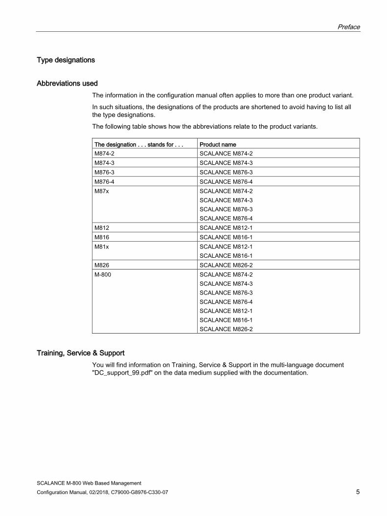
Abbreviations used The information in the configuration manual often applies to more than one product variant.
In such situations, the designations of the products are shortened to avoid having to list all the type designations.
The following table shows how the abbreviations relate to the product variants. The designation . . . stands for . . . Product name M874-2 SCALANCE M874-2 M874-3 SCALANCE M874-3 M876-3 SCALANCE M876-3 M876-4 SCALANCE M876-4 M87x SCALANCE M874-2
SCALANCE M874-3 SCALANCE M876-3 SCALANCE M876-4
M812 SCALANCE M812-1 M816 SCALANCE M816-1 M81x SCALANCE M812-1
SCALANCE M816-1 M826 SCALANCE M826-2 M-800 SCALANCE M874-2
SCALANCE M874-3 SCALANCE M876-3 SCALANCE M876-4 SCALANCE M812-1 SCALANCE M816-1 SCALANCE M826-2
Training, Service & Support You will find information on Training, Service & Support in the multi-language document "DC_support_99.pdf" on the data medium supplied with the documentation.

Preface
SCALANCE M-800 Web Based Management 6 Configuration Manual, 02/2018, C79000-G8976-C330-07
SIMATIC NET glossary Explanations of many of the specialist terms used in this documentation can be found in the SIMATIC NET glossary.
You will find the SIMATIC NET glossary here:
● SIMATIC NET Manual Collection or product DVD
The DVD ships with certain SIMATIC NET products.
● On the Internet under the following address:
50305045 (https://support.industry.siemens.com/cs/ww/en/view/50305045)
Security information Siemens provides products and solutions with industrial security functions that support the secure operation of plants, systems, machines and networks.
In order to protect plants, systems, machines and networks against cyber threats, it is necessary to implement – and continuously maintain – a holistic, state-of-the-art industrial security concept. Siemens’ products and solutions constitute one element of such a concept.
Customers are responsible for preventing unauthorized access to their plants, systems, machines and networks. Such systems, machines and components should only be connected to an enterprise network or the internet if and to the extent such a connection is necessary and only when appropriate security measures (e.g. firewalls and/or network segmentation) are in place.
Additionally, Siemens’ guidance on appropriate security measures should be taken into account. For additional information on industrial security measures that may be implemented, please visit Link: (https://www.siemens.com/industrialsecurity)
Siemens’ products and solutions undergo continuous development to make them more secure. Siemens strongly recommends that product updates are applied as soon as they are available and that the latest product versions are used. Use of product versions that are no longer supported, and failure to apply the latest updates may increase customers’ exposure to cyber threats.
To stay informed about product updates, subscribe to the Siemens Industrial Security RSS Feed under Link: (https://www.siemens.com/industrialsecurity)
Firmware The firmware is signed and encrypted. This ensures that only firmware created by Siemens can be downloaded to the device.

Preface
SCALANCE M-800 Web Based Management Configuration Manual, 02/2018, C79000-G8976-C330-07 7
License conditions
Note Open source software
Read the license conditions for open source software carefully before using the product.
You will find license conditions in the following documents on the supplied data medium:
● OSS_Scalance-M-800-S615_86.htm
Trademarks The following and possibly other names not identified by the registered trademark sign ® are registered trademarks of Siemens AG:
SCALANCE, SINEMA, KEY-PLUG, C-PLUG

Preface
SCALANCE M-800 Web Based Management 8 Configuration Manual, 02/2018, C79000-G8976-C330-07
SCALANCE M-800 Web Based Management Configuration Manual, 02/2018, C79000-G8976-C330-07 9
Table of contents
Preface ................................................................................................................................................... 3
1 Description ............................................................................................................................................ 15
1.1 Function .................................................................................................................................. 15
1.2 Configuration examples .......................................................................................................... 17 1.2.1 Overview ................................................................................................................................. 17 1.2.2 SCALANCE M874/M81x as Internet access .......................................................................... 17 1.2.3 Direct communication of stations ............................................................................................ 19 1.2.4 Telecontrol via the mobile wireless network ........................................................................... 21 1.2.5 Telecontrol via dedicated line ................................................................................................. 22 1.2.6 Mobile access to plants and plant sections ............................................................................ 22 1.2.7 Plant access via a remote maintenance center ...................................................................... 24 1.2.8 TeleControl with SINEMA RC ................................................................................................. 25
1.3 Requirements for operation .................................................................................................... 26 1.3.1 For operation with M87x ......................................................................................................... 26 1.3.2 For operation with M81x ......................................................................................................... 27 1.3.3 For operation with M826 ......................................................................................................... 28
1.4 Configuration limits for WBM and CLI ..................................................................................... 30
1.5 Configuration limits for SINEMA RC ....................................................................................... 31
1.6 Hardware equipment and system functions ........................................................................... 31
1.7 PLUG ...................................................................................................................................... 34 1.7.1 C-PLUG and KEY-PLUG ........................................................................................................ 34 1.7.2 PRESET PLUG ....................................................................................................................... 35
2 Technical basics ................................................................................................................................... 37
2.1 IPv4 address, subnet mask and address of the gateway ....................................................... 37
2.2 VLAN ....................................................................................................................................... 39 2.2.1 VLAN ....................................................................................................................................... 39 2.2.2 VLAN tagging .......................................................................................................................... 40
2.3 SNMP ...................................................................................................................................... 42
2.4 ICMP ....................................................................................................................................... 44
2.5 Security functions .................................................................................................................... 46 2.5.1 User management .................................................................................................................. 46 2.5.2 Firewall .................................................................................................................................... 48 2.5.3 NAT ......................................................................................................................................... 51 2.5.4 NAT and firewall ...................................................................................................................... 53 2.5.5 Certificates .............................................................................................................................. 55 2.5.6 VPN ......................................................................................................................................... 55 2.5.6.1 IPsec VPN ............................................................................................................................... 56 2.5.6.2 OpenVPN ................................................................................................................................ 59 2.5.6.3 VPN connection establishment ............................................................................................... 60

Table of contents
SCALANCE M-800 Web Based Management 10 Configuration Manual, 02/2018, C79000-G8976-C330-07
2.6 Redundancy ........................................................................................................................... 66 2.6.1 Spanning Tree........................................................................................................................ 66 2.6.1.1 RSTP ...................................................................................................................................... 67 2.6.2 VRRPv3 ................................................................................................................................. 68
3 Security recommendation...................................................................................................................... 69
4 Configuring with Web Based Management ............................................................................................ 75
4.1 Web Based Management ...................................................................................................... 75
4.2 Starting and logging in ........................................................................................................... 76
4.3 "Wizard" menu ....................................................................................................................... 79 4.3.1 Basic Wizard .......................................................................................................................... 79 4.3.2 IP settings .............................................................................................................................. 80 4.3.3 Device Settings ...................................................................................................................... 81 4.3.4 DSL ........................................................................................................................................ 82 4.3.5 SHDSL ................................................................................................................................... 85 4.3.6 SIM ......................................................................................................................................... 87 4.3.7 Operator ................................................................................................................................. 89 4.3.8 Time settings .......................................................................................................................... 92 4.3.9 DDNS ..................................................................................................................................... 94 4.3.10 SINEMA RC ........................................................................................................................... 95 4.3.11 Summary ................................................................................................................................ 98
4.4 "Information" menu............................................................................................................... 100 4.4.1 Start Page ............................................................................................................................ 100 4.4.2 Versions ............................................................................................................................... 105 4.4.3 Identification & Maintenance ................................................................................................ 107 4.4.4 ARP Table ............................................................................................................................ 108 4.4.5 Log Tables ........................................................................................................................... 109 4.4.5.1 Event Log ............................................................................................................................. 109 4.4.5.2 Security Log ......................................................................................................................... 111 4.4.5.3 Firewall Log .......................................................................................................................... 113 4.4.6 Faults ................................................................................................................................... 115 4.4.7 DHCP Server ....................................................................................................................... 116 4.4.8 SNMP ................................................................................................................................... 117 4.4.9 LLDP .................................................................................................................................... 118 4.4.10 Routing ................................................................................................................................. 119 4.4.11 Mobile ................................................................................................................................... 120 4.4.11.1 Overview .............................................................................................................................. 120 4.4.11.2 Signal Recorder ................................................................................................................... 122 4.4.12 DSL ...................................................................................................................................... 123 4.4.12.1 Overview .............................................................................................................................. 123 4.4.12.2 DSL Data Rate ..................................................................................................................... 125 4.4.12.3 Streams ................................................................................................................................ 126 4.4.13 SHDSL ................................................................................................................................. 127 4.4.14 IPsec VPN ............................................................................................................................ 129 4.4.15 SINEMA RC ......................................................................................................................... 130 4.4.16 OpenVPN client.................................................................................................................... 132 4.4.17 Redundancy ......................................................................................................................... 133 4.4.17.1 Overview .............................................................................................................................. 133 4.4.17.2 Spanning Tree...................................................................................................................... 135
Table of contents
SCALANCE M-800 Web Based Management Configuration Manual, 02/2018, C79000-G8976-C330-07 11
4.4.18 Security ................................................................................................................................. 137 4.4.18.1 Overview ............................................................................................................................... 137 4.4.18.2 Supported Function Rights ................................................................................................... 140 4.4.18.3 Roles ..................................................................................................................................... 141 4.4.18.4 Groups .................................................................................................................................. 142 4.4.19 VRRPv3 Statistics ................................................................................................................. 143
4.5 "System" menu ..................................................................................................................... 145 4.5.1 Configuration ......................................................................................................................... 145 4.5.2 General ................................................................................................................................. 149 4.5.2.1 Device ................................................................................................................................... 149 4.5.2.2 Coordinates ........................................................................................................................... 150 4.5.3 Restart .................................................................................................................................. 152 4.5.4 Load&Save ........................................................................................................................... 154 4.5.4.1 File list ................................................................................................................................... 154 4.5.4.2 HTTP ..................................................................................................................................... 155 4.5.4.3 TFTP ..................................................................................................................................... 158 4.5.4.4 SFTP ..................................................................................................................................... 161 4.5.4.5 Passwords ............................................................................................................................ 165 4.5.5 Events ................................................................................................................................... 166 4.5.5.1 Configuration ......................................................................................................................... 166 4.5.5.2 Severity Filters ...................................................................................................................... 169 4.5.6 SMTP client ........................................................................................................................... 170 4.5.7 SNMP .................................................................................................................................... 172 4.5.7.1 General ................................................................................................................................. 172 4.5.7.2 Traps ..................................................................................................................................... 174 4.5.7.3 v3 Groups ............................................................................................................................. 175 4.5.7.4 v3 users ................................................................................................................................ 178 4.5.8 System Time ......................................................................................................................... 180 4.5.8.1 Manual Setting ...................................................................................................................... 181 4.5.8.2 SNTP Client .......................................................................................................................... 183 4.5.8.3 NTP client ............................................................................................................................. 186 4.5.8.4 SIMATIC Time Client ............................................................................................................ 189 4.5.8.5 NTP Server ........................................................................................................................... 190 4.5.9 Automatic Logout .................................................................................................................. 191 4.5.10 Button .................................................................................................................................... 192 4.5.11 Syslog client .......................................................................................................................... 193 4.5.12 Fault Monitoring .................................................................................................................... 195 4.5.12.1 Link Change .......................................................................................................................... 195 4.5.12.2 Mobile wireless ..................................................................................................................... 197 4.5.13 PLUG .................................................................................................................................... 197 4.5.13.1 Configuration ......................................................................................................................... 197 4.5.13.2 License .................................................................................................................................. 201 4.5.14 Ping ....................................................................................................................................... 203 4.5.15 DCP Discovery ...................................................................................................................... 204 4.5.16 SMS ...................................................................................................................................... 206 4.5.16.1 General ................................................................................................................................. 206 4.5.16.2 Event SMS ............................................................................................................................ 207 4.5.16.3 SMS Command ..................................................................................................................... 210 4.5.16.4 SMS Relay (Outgoing) .......................................................................................................... 212 4.5.16.5 SMS Relay (Incoming) .......................................................................................................... 213

Table of contents
SCALANCE M-800 Web Based Management 12 Configuration Manual, 02/2018, C79000-G8976-C330-07
4.5.17 DNS ...................................................................................................................................... 216 4.5.17.1 DNS client ............................................................................................................................ 216 4.5.17.2 DNS Proxy ........................................................................................................................... 217 4.5.17.3 DDNS client .......................................................................................................................... 217 4.5.18 DHCP ................................................................................................................................... 219 4.5.18.1 DHCP Client ......................................................................................................................... 219 4.5.18.2 DHCP Server ....................................................................................................................... 222 4.5.18.3 DHCP options ...................................................................................................................... 224 4.5.18.4 Static Leases ........................................................................................................................ 227 4.5.19 cRSP / SRS .......................................................................................................................... 228 4.5.20 Proxy Server ........................................................................................................................ 230 4.5.21 SINEMA RC ......................................................................................................................... 231
4.6 "Interfaces" menu ................................................................................................................. 235 4.6.1 Ethernet ................................................................................................................................ 235 4.6.1.1 Configuration ........................................................................................................................ 237 4.6.2 Mobile wireless..................................................................................................................... 239 4.6.2.1 SIM ....................................................................................................................................... 239 4.6.2.2 Mobile wireless provider ...................................................................................................... 241 4.6.2.3 Connection Check ................................................................................................................ 243 4.6.3 DSL ...................................................................................................................................... 244 4.6.4 SHDSL ................................................................................................................................. 247 4.6.4.1 Overview .............................................................................................................................. 247 4.6.4.2 Configuration ........................................................................................................................ 248 4.6.4.3 Connection Check ................................................................................................................ 252
4.7 "Layer 2" menu ..................................................................................................................... 254 4.7.1 Layer 2 configuration ........................................................................................................... 254 4.7.2 VLAN .................................................................................................................................... 254 4.7.2.1 General ................................................................................................................................ 254 4.7.2.2 Port Based VLAN ................................................................................................................. 258 4.7.3 Dynamic MAC Aging ............................................................................................................ 260 4.7.4 Spanning Tree...................................................................................................................... 261 4.7.4.1 General ................................................................................................................................ 261 4.7.4.2 ST general ............................................................................................................................ 262 4.7.4.3 ST port ................................................................................................................................. 263 4.7.5 LLDP .................................................................................................................................... 267
4.8 "Layer 3" menu ..................................................................................................................... 269 4.8.1 Static routes ......................................................................................................................... 269 4.8.2 Subnets ................................................................................................................................ 271 4.8.2.1 Overview .............................................................................................................................. 271 4.8.2.2 Configuration ........................................................................................................................ 274 4.8.3 NAT ...................................................................................................................................... 275 4.8.3.1 Masquerading ...................................................................................................................... 275 4.8.3.2 NAPT .................................................................................................................................... 276 4.8.3.3 Source NAT .......................................................................................................................... 278 4.8.3.4 NETMAP .............................................................................................................................. 280 4.8.4 VRRPv3 ............................................................................................................................... 282 4.8.4.1 Routers ................................................................................................................................. 282 4.8.4.2 Configuration ........................................................................................................................ 285 4.8.4.3 Address Overview ................................................................................................................ 287 4.8.4.4 Address Configuration ......................................................................................................... 288 4.8.4.5 Interface Tracking ................................................................................................................ 289
Table of contents
SCALANCE M-800 Web Based Management Configuration Manual, 02/2018, C79000-G8976-C330-07 13
4.9 "Security" menu .................................................................................................................... 291 4.9.1 Users ..................................................................................................................................... 291 4.9.1.1 Local users ............................................................................................................................ 291 4.9.1.2 Roles ..................................................................................................................................... 294 4.9.1.3 Groups .................................................................................................................................. 296 4.9.2 Passwords ............................................................................................................................ 297 4.9.3 AAA ....................................................................................................................................... 299 4.9.3.1 General ................................................................................................................................. 299 4.9.3.2 RADIUS client ....................................................................................................................... 300 4.9.4 Certificates ............................................................................................................................ 303 4.9.4.1 Overview ............................................................................................................................... 303 4.9.4.2 Certificates ............................................................................................................................ 305 4.9.5 Firewall .................................................................................................................................. 308 4.9.5.1 General ................................................................................................................................. 308 4.9.5.2 Predefined IPv4 rules............................................................................................................ 309 4.9.5.3 IP services ............................................................................................................................ 311 4.9.5.4 ICMP services ....................................................................................................................... 312 4.9.5.5 IP protocols ........................................................................................................................... 313 4.9.5.6 IP rules .................................................................................................................................. 314 4.9.6 IPsec VPN ............................................................................................................................. 316 4.9.6.1 General ................................................................................................................................. 316 4.9.6.2 Remote End .......................................................................................................................... 317 4.9.6.3 Connections .......................................................................................................................... 319 4.9.6.4 Authentication ....................................................................................................................... 322 4.9.6.5 Phase 1 ................................................................................................................................. 323 4.9.6.6 Phase 2 ................................................................................................................................. 326 4.9.7 OpenVPN Client .................................................................................................................... 328 4.9.7.1 General ................................................................................................................................. 328 4.9.7.2 Connections .......................................................................................................................... 329 4.9.7.3 Remote ................................................................................................................................. 331 4.9.7.4 Authentication ....................................................................................................................... 332
5 Upkeep and maintenance ................................................................................................................... 335
5.1 Device configuration with PRESET-PLUG ........................................................................... 335
5.2 Firmware update via WBM and CLI not possible ................................................................. 339
5.3 Restoring the factory settings ............................................................................................... 340
A Appendix A ......................................................................................................................................... 343
A.1 Command SMS message ..................................................................................................... 343
Index................................................................................................................................................... 345

Table of contents
SCALANCE M-800 Web Based Management 14 Configuration Manual, 02/2018, C79000-G8976-C330-07

SCALANCE M-800 Web Based Management Configuration Manual, 02/2018, C79000-G8976-C330-07 15
Description 1 1.1 Function
Configuration Configuration of all parameters using the
● Web Based Management (WBM) via HTTP and HTTPS.
● Command Line Interface (CLI) via Telnet and SSH.
Security functions ● Router with NAT function
– IP masquerading
– NAPT
– SourceNAT
– NETMAP
● Password protection
● Firewall function
– Port forwarding
– IP firewall with stateful packet inspection (layer 3 and 4)
– Global and user-defined firewall rules
● VPN functions
To establish a VPN (Virtual Private Network), the following functions are available
– IPsec VPN
– OpenVPN client
● SINEMA RC client
● Proxy server
● Siemens Remote Service (SRS)
Description 1.1 Function
SCALANCE M-800 Web Based Management 16 Configuration Manual, 02/2018, C79000-G8976-C330-07
Monitoring / diagnostics / maintenance ● LEDs
Display of operating statuses via the LED display. You will find further information on this in the Operating Instructions of the device.
● Logging
For monitoring have the events logged.
● SNMP
For monitoring and controlling network components such as routers or switches from a central station.
Other functions ● Time-of-day synchronization
– NTP
– SIMATIC Time Client
– SNTP
● DHCP
– DHCP server (local network)
– DHCP client
● Virtual networks (VLAN)
To structure Industrial Ethernet networks with a fast growing number of nodes, a physical network can be divided into several virtual subnets
● Digital input/digital output
● Dynamic DNS client
● DNS client / DNS proxy
● SMTP client
Description 1.2 Configuration examples
SCALANCE M-800 Web Based Management Configuration Manual, 02/2018, C79000-G8976-C330-07 17
1.2 Configuration examples
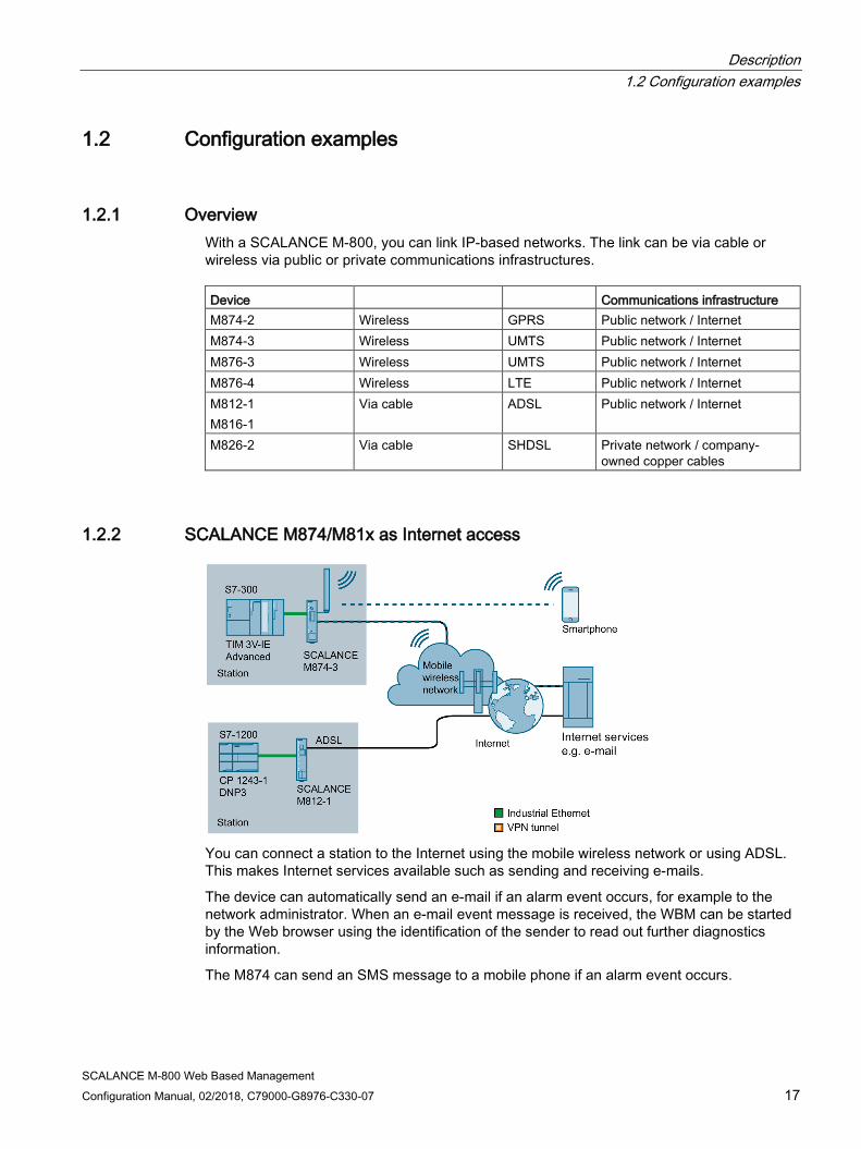
1.2.1 Overview With a SCALANCE M-800, you can link IP-based networks. The link can be via cable or wireless via public or private communications infrastructures. Device Communications infrastructure M874-2 Wireless GPRS Public network / Internet M874-3 Wireless UMTS Public network / Internet M876-3 Wireless UMTS Public network / Internet M876-4 Wireless LTE Public network / Internet M812-1 M816-1
Via cable ADSL Public network / Internet
M826-2 Via cable SHDSL Private network / company-owned copper cables
1.2.2 SCALANCE M874/M81x as Internet access
You can connect a station to the Internet using the mobile wireless network or using ADSL. This makes Internet services available such as sending and receiving e-mails.
The device can automatically send an e-mail if an alarm event occurs, for example to the network administrator. When an e-mail event message is received, the WBM can be started by the Web browser using the identification of the sender to read out further diagnostics information.
The M874 can send an SMS message to a mobile phone if an alarm event occurs.
Description 1.2 Configuration examples
SCALANCE M-800 Web Based Management 18 Configuration Manual, 02/2018, C79000-G8976-C330-07
Requirement ● The M-800 is reachable via an Admin PC
Procedure To configure Internet access, follow the steps below:
1. Establish a connection to the WAN, see section Interfaces (Page 235).
2. To allow access to the required Internet services, set up firewall rules, see section Firewall (Page 308).
3. Setup your application for the Internet services.
Description 1.2 Configuration examples
SCALANCE M-800 Web Based Management Configuration Manual, 02/2018, C79000-G8976-C330-07 19
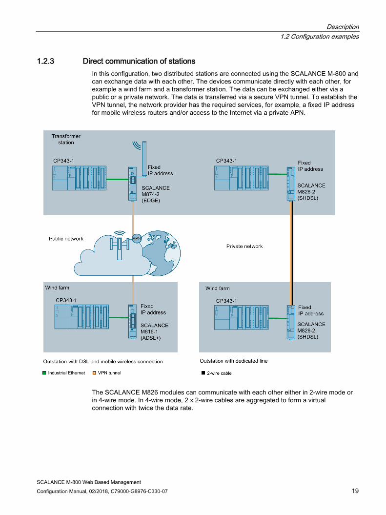
1.2.3 Direct communication of stations In this configuration, two distributed stations are connected using the SCALANCE M-800 and can exchange data with each other. The devices communicate directly with each other, for example a wind farm and a transformer station. The data can be exchanged either via a public or a private network. The data is transferred via a secure VPN tunnel. To establish the VPN tunnel, the network provider has the required services, for example, a fixed IP address for mobile wireless routers and/or access to the Internet via a private APN.
The SCALANCE M826 modules can communicate with each other either in 2-wire mode or in 4-wire mode. In 4-wire mode, 2 x 2-wire cables are aggregated to form a virtual connection with twice the data rate.

Description 1.2 Configuration examples
SCALANCE M-800 Web Based Management 20 Configuration Manual, 02/2018, C79000-G8976-C330-07
Requirements ● The M-800 is reachable via an Admin PC.
● To establish a VPN tunnel:
– M81x and M874
The network provider offers the required services, for example, a fixed IP address for mobile wireless routers and/or an access to the Internet via a private APN.
– M826
The devices have a fixed IP address and are in routing mode.
Procedure To configure data transfer via a VPN tunnel, follow the steps below:
1. Establish a connection to the public or private network, refer to the section Interfaces (Page 235).
2. Connect a controller, for example using a CP 343-1 to an Ethernet interface of the M-800.
3. Establish a VPN connection between the two M800 devices, refer to the section IPsec VPN (Page 316).
4. Set up the connected controllers for data communication.
Description 1.2 Configuration examples
SCALANCE M-800 Web Based Management Configuration Manual, 02/2018, C79000-G8976-C330-07 21
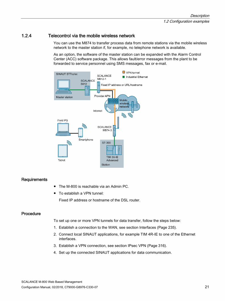
1.2.4 Telecontrol via the mobile wireless network You can use the M874 to transfer process data from remote stations via the mobile wireless network to the master station if, for example, no telephone network is available.
As an option, the software of the master station can be expanded with the Alarm Control Center (ACC) software package. This allows fault/error messages from the plant to be forwarded to service personnel using SMS messages, fax or e-mail.
Requirements ● The M-800 is reachable via an Admin PC.
● To establish a VPN tunnel:
Fixed IP address or hostname of the DSL router.
Procedure To set up one or more VPN tunnels for data transfer, follow the steps below:
1. Establish a connection to the WAN, see section Interfaces (Page 235).
2. Connect local SINAUT applications, for example TIM 4R-IE to one of the Ethernet interfaces.
3. Establish a VPN connection, see section IPsec VPN (Page 316).
4. Set up the connected SINAUT applications for data communication.
Description 1.2 Configuration examples
SCALANCE M-800 Web Based Management 22 Configuration Manual, 02/2018, C79000-G8976-C330-07
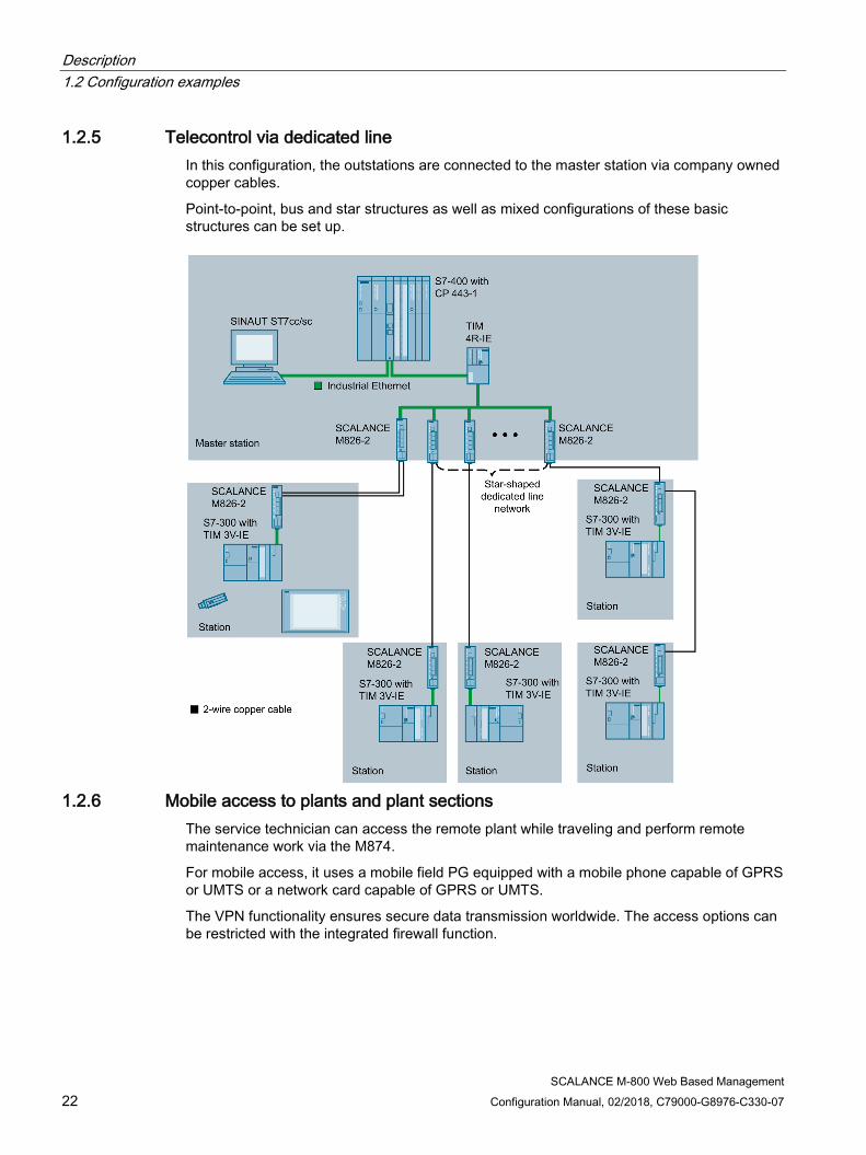
1.2.5 Telecontrol via dedicated line In this configuration, the outstations are connected to the master station via company owned copper cables.
Point-to-point, bus and star structures as well as mixed configurations of these basic structures can be set up.
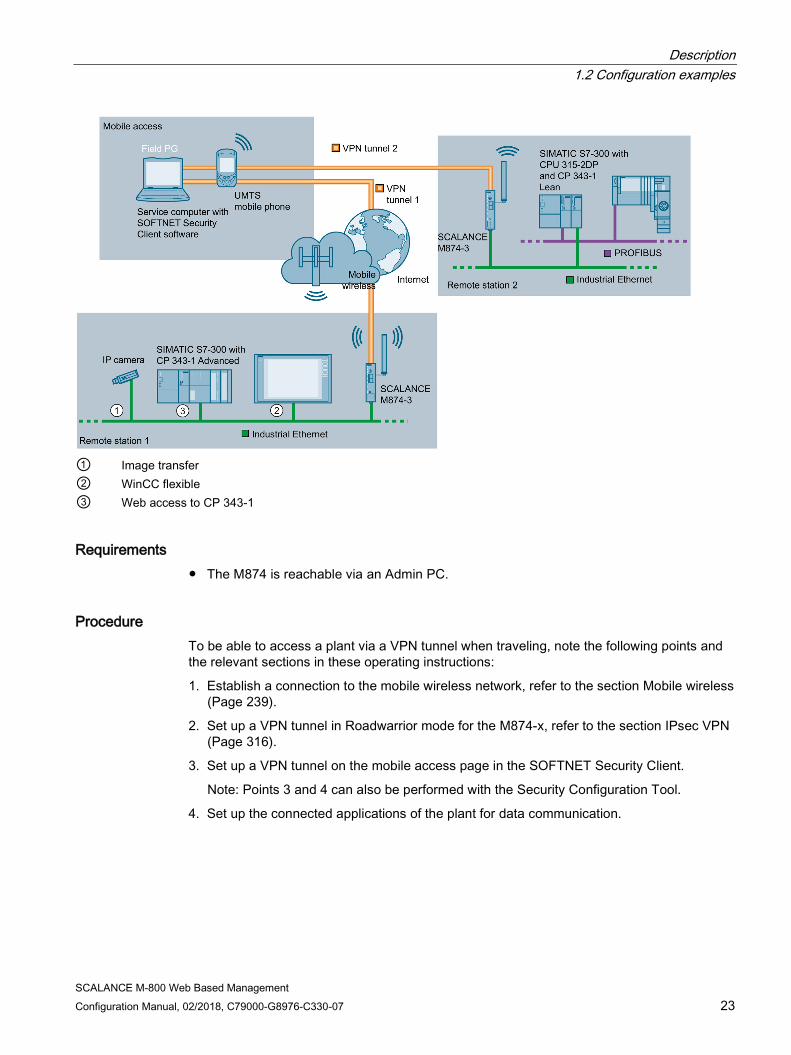
1.2.6 Mobile access to plants and plant sections
The service technician can access the remote plant while traveling and perform remote maintenance work via the M874.
For mobile access, it uses a mobile field PG equipped with a mobile phone capable of GPRS or UMTS or a network card capable of GPRS or UMTS.
The VPN functionality ensures secure data transmission worldwide. The access options can be restricted with the integrated firewall function.
Description 1.2 Configuration examples
SCALANCE M-800 Web Based Management Configuration Manual, 02/2018, C79000-G8976-C330-07 23
① Image transfer ② WinCC flexible ③ Web access to CP 343-1
Requirements ● The M874 is reachable via an Admin PC.
Procedure To be able to access a plant via a VPN tunnel when traveling, note the following points and the relevant sections in these operating instructions:
1. Establish a connection to the mobile wireless network, refer to the section Mobile wireless (Page 239).
2. Set up a VPN tunnel in Roadwarrior mode for the M874-x, refer to the section IPsec VPN (Page 316).
3. Set up a VPN tunnel on the mobile access page in the SOFTNET Security Client.
Note: Points 3 and 4 can also be performed with the Security Configuration Tool.
4. Set up the connected applications of the plant for data communication.

Description 1.2 Configuration examples
SCALANCE M-800 Web Based Management 24 Configuration Manual, 02/2018, C79000-G8976-C330-07
1.2.7 Plant access via a remote maintenance center Another variant is client access from a remote maintenance master station. The remote maintenance master station is connected to the Internet via the VPN server SCALANCE S612. This protects the remote maintenance master station against unauthorized access. The plant communicates via the SCALANCE M874 that establishes a VPN tunnel with the SCALANCE S612. This allows, for example, a service technician to control and monitor a plant from the remote maintenance master station.
① Web access to CP 343-1 ② Image transfer ③ WinCC flexible
Procedure To be able to access a plant via a remote maintenance master station, follow the steps below:
1. Establish the Ethernet connection between the M874 and the connected Admin PC.
2. Establish a connection to the mobile wireless network, see section Mobile wireless (Page 239).
3. Configure the VPN connection for the remote maintenance master station on the SCALANCE S612 with the Security Configuration Tool.
4. Set up a VPN tunnel in standard mode, see section IPsec VPN (Page 316).
5. Set up the connected applications of the plant for data communication.
Description 1.2 Configuration examples
SCALANCE M-800 Web Based Management Configuration Manual, 02/2018, C79000-G8976-C330-07 25
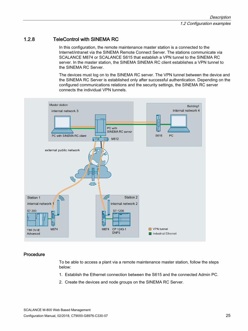
1.2.8 TeleControl with SINEMA RC In this configuration, the remote maintenance master station is a connected to the Internet/intranet via the SINEMA Remote Connect Server. The stations communicate via SCALANCE M874 or SCALANCE S615 that establish a VPN tunnel to the SINEMA RC server. In the master station, the SINEMA SINEMA RC client establishes a VPN tunnel to the SINEMA RC Server.
The devices must log on to the SINEMA RC server. The VPN tunnel between the device and the SINEMA RC Server is established only after successful authentication. Depending on the configured communications relations and the security settings, the SINEMA RC server connects the individual VPN tunnels.
Procedure To be able to access a plant via a remote maintenance master station, follow the steps below:
1. Establish the Ethernet connection between the S615 and the connected Admin PC.
2. Create the devices and node groups on the SINEMA RC Server.
Description 1.3 Requirements for operation
SCALANCE M-800 Web Based Management 26 Configuration Manual, 02/2018, C79000-G8976-C330-07
3. Configure the connection to the SINEMA RC server on the device, refer to the section SINEMA RC (Page 231).
4. Set up the connected applications of the plant for data communication.
1.3 Requirements for operation
1.3.1 For operation with M87x
Antenna The frequency range of the antenna depends on the device being used:
● SCALANCE M874-2
EGPRS / GPRS (2G): 850, 900, 1800 or 1900 MHz
● SCALANCE M874-3 / M876-3
UMTS (3G): 800, 850, 900, 1900 or 2100 MHz
● SCALANCE M876-4
LTE (4G): 800, 900, 1800, 2100 or 2600 MHz
Use antennas from the accessories program of the SCALANCE M-800 device. You will find further information on this in the device-specific operating instructions.
Note
You should also note the national approvals for the SCALANCE M-800 devices. You will find the current status of the national approval on the Internet at the following address: http://www.automation.siemens.com/mcms/industrial-communication/en/support/ik-info/Documents/Online_CountryApprovals_GSM_UMTS_products.pdf (http://w3.siemens.com/mcms/industrial-communication/en/support/ik-info/Documents/Online_CountryApprovals_GSM_UMTS_products.pdf)
Power supply A power supply with a voltage between 12 VDC and 24 VDC that can provide sufficient current.
You will find further information on this in the device-specific operating instructions.

Description 1.3 Requirements for operation
SCALANCE M-800 Web Based Management Configuration Manual, 02/2018, C79000-G8976-C330-07 27
SIM card A standard SIM card from the chosen mobile wireless provider.
PIN
The PIN (= Personal Identification Number) for the SIM card
LTE / UMTS / EGPRS / GPRS activation
The SIM card must be activated for the services in the mobile wireless network by your mobile wireless provider.
The access data must be known:
● Access point name (APN)
● User name
● Password
Configuration In the factory settings, the SCALANCE M81x can be reached as follows for initial configuration: Default values set in the factory Ethernet interface for the configuration
M874: P1 ... P2 M876: P1 ... P4
IP address 192.168.1.1 Subnet mask 255.255.255.0 WBM Access using HTTPS: TCP port 443 CLI Access using SSH, TCP port 22 User name admin (cannot be changed) Password
admin The password needs to be changed after the first logon or after a "Restore Factory Defaults and Restart"
You will find more information in "Web Based Management" and in "Starting and logging in (Page 76)".
1.3.2 For operation with M81x
Power supply A power supply with a voltage between 12 VDC and 24 VDC that can provide sufficient current.
You will find further information on this in the device-specific operating instructions.

Description 1.3 Requirements for operation
SCALANCE M-800 Web Based Management 28 Configuration Manual, 02/2018, C79000-G8976-C330-07
ADSL connection An ADSL connection of the chosen DSL provider.
ADSL activation
The DSL connection must be activated by your DSL provider.
The access data must be known:
● User name
● Password
● VCI / VPI
● Encapsulation
Configuration In the factory settings, the SCALANCE M81x can be reached as follows for initial configuration: Default values set in the factory Ethernet interface for the configuration
M812: P1 M816: P1 ... P4
IP address 192.168.1.1 WBM Access using HTTPS: TCP port 443 CLI Access using SSH, TCP port 22 Subnet mask 255.255.255.0 User name admin (cannot be changed) Password
admin The password needs to be changed after the first logon or after a "Restore Factory Defaults and Restart"
You will find more information in "Web Based Management" and in "Starting and logging in (Page 76)".
1.3.3 For operation with M826
Power supply A power supply with a voltage between 12 VDC and 24 VDC that can provide sufficient current.
You will find further information on this in the device-specific operating instructions.
SHDSL connection Company-owned copper cables
Description 1.3 Requirements for operation
SCALANCE M-800 Web Based Management Configuration Manual, 02/2018, C79000-G8976-C330-07 29
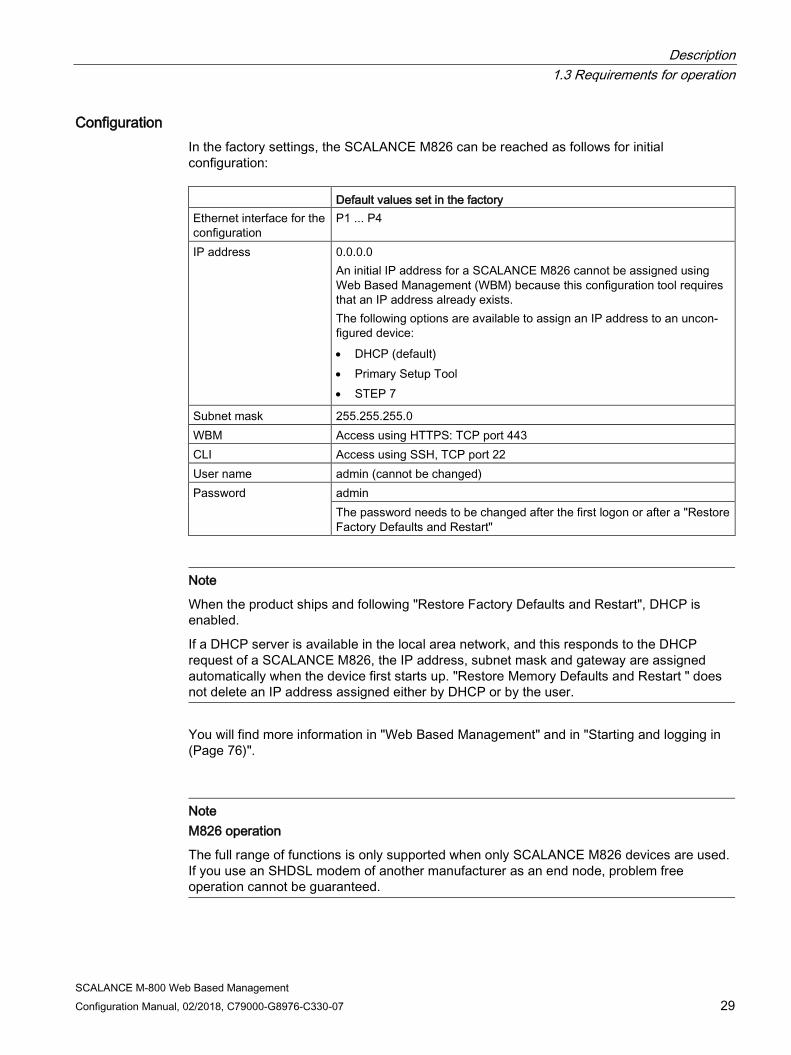
Configuration In the factory settings, the SCALANCE M826 can be reached as follows for initial configuration: Default values set in the factory Ethernet interface for the configuration
P1 ... P4
IP address 0.0.0.0 An initial IP address for a SCALANCE M826 cannot be assigned using Web Based Management (WBM) because this configuration tool requires that an IP address already exists. The following options are available to assign an IP address to an uncon-figured device: • DHCP (default) • Primary Setup Tool • STEP 7
Subnet mask 255.255.255.0 WBM Access using HTTPS: TCP port 443 CLI Access using SSH, TCP port 22 User name admin (cannot be changed) Password
admin The password needs to be changed after the first logon or after a "Restore Factory Defaults and Restart"
Note
When the product ships and following "Restore Factory Defaults and Restart", DHCP is enabled.
If a DHCP server is available in the local area network, and this responds to the DHCP request of a SCALANCE M826, the IP address, subnet mask and gateway are assigned automatically when the device first starts up. "Restore Memory Defaults and Restart " does not delete an IP address assigned either by DHCP or by the user.
You will find more information in "Web Based Management" and in "Starting and logging in (Page 76)".
Note M826 operation
The full range of functions is only supported when only SCALANCE M826 devices are used. If you use an SHDSL modem of another manufacturer as an end node, problem free operation cannot be guaranteed.
Description 1.4 Configuration limits for WBM and CLI
SCALANCE M-800 Web Based Management 30 Configuration Manual, 02/2018, C79000-G8976-C330-07
1.4 Configuration limits for WBM and CLI
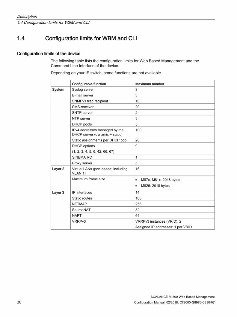
Configuration limits of the device The following table lists the configuration limits for Web Based Management and the Command Line Interface of the device.
Depending on your IE switch, some functions are not available. Configurable function Maximum number System Syslog server 3
E-mail server 3 SNMPv1 trap recipient 10 SMS receiver 20 SNTP server 2 NTP server 3 DHCP pools 5 IPv4 addresses managed by the DHCP server (dynamic + static)
100
Static assignments per DHCP pool 20 DHCP options (1, 2, 3, 4, 5, 6, 42, 66, 67)
9
SINEMA RC 1 Proxy server 5
Layer 2 Virtual LANs (port-based; including VLAN 1)
16
Maximum frame size • M87x, M81x: 2048 bytes • M826: 2018 bytes
Layer 3 IP interfaces 14 Static routes 100 NETMAP 256 SourceNAT 32 NAPT 64 VRRPv3 VRRPv3 instances (VRID): 2
Assigned IP addresses: 1 per VRID

Description 1.5 Configuration limits for SINEMA RC
SCALANCE M-800 Web Based Management Configuration Manual, 02/2018, C79000-G8976-C330-07 31
Configurable function Maximum number Security Users 30
(incl. user preset in the factory "admin") Groups 32 Roles 32
(incl. the predefined roles) RADIUS Server 4 Firewall IP protocols:16
IP services:32 ICMP services:16 IP rules: 128
IPsec VPN 20 You can create a maximum of 20 phase 2 con-nections per phase 1.
OpenVPN Connections: 5 Remote end points: 25
1.5 Configuration limits for SINEMA RC Maximum overall data transfer for all devices: 800 Mbps
Maximum number of devices and users connected simultaneously: 1024 devices with 1 subnet each
User/device combinations can be freely selected up to the maximum overall quantity structure.
As the number of subnets is also dependent on the communication relationships permitted among one another, for example, these must be checked/questioned and restricted, where necessary. If devices do not need to communicate with one another, this function should be disabled to ensure optimum device behavior.
If the devices are to communicate with each other, the maximum number of devices and users connected simultaneously is: 200 devices with 8 subnets each communicating with each other
1.6 Hardware equipment and system functions
Availability of hardware The following table shows the hardware of the devices.
Description 1.6 Hardware equipment and system functions
SCALANCE M-800 Web Based Management 32 Configuration Manual, 02/2018, C79000-G8976-C330-07
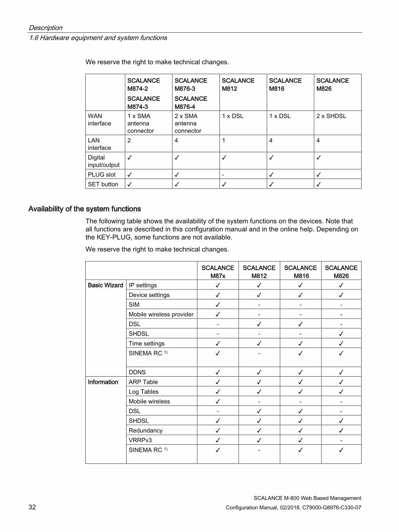
We reserve the right to make technical changes. SCALANCE
M874-2 SCALANCE M874-3
SCALANCE M876-3 SCALANCE M876-4
SCALANCE M812
SCALANCE M816
SCALANCE M826
WAN interface
1 x SMA antenna connector
2 x SMA antenna connector
1 x DSL 1 x DSL 2 x SHDSL
LAN interface
2 4 1 4 4
Digital input/output
✓ ✓ ✓ ✓ ✓
PLUG slot ✓ ✓ - ✓ ✓ SET button ✓ ✓ ✓ ✓ ✓
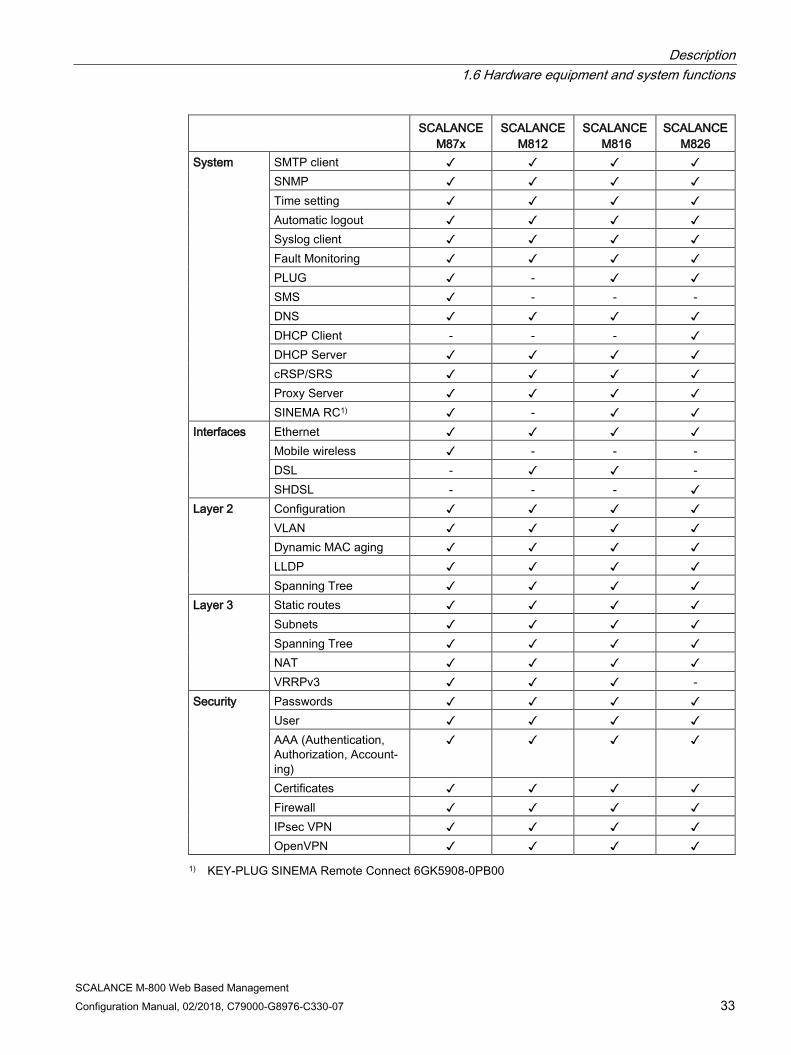
Availability of the system functions The following table shows the availability of the system functions on the devices. Note that all functions are described in this configuration manual and in the online help. Depending on the KEY-PLUG, some functions are not available.
We reserve the right to make technical changes. SCALANCE
M87x SCALANCE
M812 SCALANCE
M816 SCALANCE
M826 Basic Wizard IP settings ✓ ✓ ✓ ✓
Device settings ✓ ✓ ✓ ✓ SIM ✓ - - - Mobile wireless provider ✓ - - - DSL - ✓ ✓ - SHDSL - - - ✓ Time settings ✓ ✓ ✓ ✓ SINEMA RC 1) ✓
- ✓
✓
DDNS ✓ ✓ ✓ ✓ Information ARP Table ✓ ✓ ✓ ✓
Log Tables ✓ ✓ ✓ ✓ Mobile wireless ✓ - - - DSL - ✓ ✓ - SHDSL ✓ ✓ ✓ ✓ Redundancy ✓ ✓ ✓ ✓ VRRPv3 ✓ ✓ ✓ - SINEMA RC 1) ✓
- ✓
✓
Description 1.6 Hardware equipment and system functions
SCALANCE M-800 Web Based Management Configuration Manual, 02/2018, C79000-G8976-C330-07 33
SCALANCE M87x
SCALANCE M812
SCALANCE M816
SCALANCE M826
System SMTP client ✓ ✓ ✓ ✓ SNMP ✓ ✓ ✓ ✓ Time setting ✓ ✓ ✓ ✓ Automatic logout ✓ ✓ ✓ ✓ Syslog client ✓ ✓ ✓ ✓ Fault Monitoring ✓ ✓ ✓ ✓ PLUG ✓ - ✓ ✓ SMS ✓ - - - DNS ✓ ✓ ✓ ✓ DHCP Client - - - ✓ DHCP Server ✓ ✓ ✓ ✓ cRSP/SRS ✓ ✓ ✓ ✓ Proxy Server ✓ ✓ ✓ ✓ SINEMA RC1) ✓ - ✓ ✓
Interfaces Ethernet ✓ ✓ ✓ ✓ Mobile wireless ✓ - - - DSL - ✓ ✓ - SHDSL - - - ✓
Layer 2 Configuration ✓ ✓ ✓ ✓ VLAN ✓ ✓ ✓ ✓ Dynamic MAC aging ✓ ✓ ✓ ✓ LLDP ✓ ✓ ✓ ✓ Spanning Tree ✓ ✓ ✓ ✓
Layer 3 Static routes ✓ ✓ ✓ ✓ Subnets ✓ ✓ ✓ ✓ Spanning Tree ✓ ✓ ✓ ✓ NAT ✓ ✓ ✓ ✓ VRRPv3 ✓ ✓ ✓ -
Security Passwords ✓ ✓ ✓ ✓ User ✓ ✓ ✓ ✓ AAA (Authentication, Authorization, Account-ing)
✓ ✓ ✓ ✓
Certificates ✓ ✓ ✓ ✓ Firewall ✓ ✓ ✓ ✓ IPsec VPN ✓ ✓ ✓ ✓ OpenVPN ✓ ✓ ✓ ✓
1) KEY-PLUG SINEMA Remote Connect 6GK5908-0PB00
Description 1.7 PLUG
SCALANCE M-800 Web Based Management 34 Configuration Manual, 02/2018, C79000-G8976-C330-07
1.7 PLUG
1.7.1 C-PLUG and KEY-PLUG
How it works The C-PLUG or KEY-PLUG is used to transfer the configuration of the old device to the new device when a device is replaced.
NOTICE
Do not remove or insert a C-PLUG / KEY-PLUG during operation!
A PLUG may only be removed or inserted when the device is turned off. The device checks whether or not a PLUG is present at one second intervals. If it is detected that the PLUG was removed, there is a restart.
If a valid KEY-PLUG was inserted in the device, the device changes to a defined error state following the restart.
When the new device starts up with the PLUG, it then continues automatically with exactly the same configuration as the old device. One exception to this can be the IP configuration if it is set over DHCP and the DHCP server has not been reconfigured accordingly.
A reconfiguration is necessary if you use functions based on MAC addresses. If an incorrect PLUG, for example from another product or a damaged PLUG is inserted, the device signals an error with the "F" LED.
You can either remove the PLUG again or select the option to reformat the PLUG.
In terms of the PLUG, devices work in two modes:
● Without PLUG
The device stores the configuration in internal memory. This mode is active when no PLUG is inserted.
● With PLUG
The configuration stored on the PLUG is displayed in WBM in "Information > PLUG". If changes are made to the configuration, the device stores the configuration directly on the PLUG and in the internal memory. This mode is active as soon as a PLUG is inserted. As soon as the device is started with a PLUG inserted, the device starts up with the configuration data on the PLUG.
Description 1.7 PLUG
SCALANCE M-800 Web Based Management Configuration Manual, 02/2018, C79000-G8976-C330-07 35
License information on the KEY-PLUG In addition to the configuration, the KEY-PLUG also contains a license that allows the use of Siemens Remote Services. Type Properties Article number C-PLUG Exchangeable storage medium (32 MB) for the
configuration data 6GK1900-0AB00
Exchangeable storage medium (256 MB) for the configuration data
6GK1900-0AB10
KEY-PLUG SINEMA RC
Exchangeable storage medium (256 MB) to enable the connection functionality to SINEMA Remote Connect and for accepting configuration data.
6GK5908-0PB00
1.7.2 PRESET PLUG
PLUG with preset function (PRESET-PLUG) With PRESET-PLUG it is possible to install the same configuration and the firmware belonging to it on several devices.
Note Using configurations with DHCP
Create a PRESET-PLUG only from device configurations that use DHCP. Otherwise disruptions will occur in network operation due to multiple identical IP addresses.
You assign fixed IP addresses extra following the basic installation.
In a PLUG that was configured as a PRESET-PLUG, the device configuration, user accounts, certificates and the firmware are stored.
Note Restore factory defaults and restart with a PRESET PLUG inserted
If you reset a device to the factory defaults, when the device restarts an inserted PRESET PLUG is formatted and the PRESET PLUG functionality is lost. You then need to create a new PRESET PLUG.
We recommend that you remove the PRESET PLUG before you reset the device to the factory settings.
For more detailed information on creating and using a PRESET PLUG refer to the section Device configuration with PRESET-PLUG (Page 335).

Description 1.7 PLUG
SCALANCE M-800 Web Based Management 36 Configuration Manual, 02/2018, C79000-G8976-C330-07

SCALANCE M-800 Web Based Management Configuration Manual, 02/2018, C79000-G8976-C330-07 37
Technical basics 2 2.1 IPv4 address, subnet mask and address of the gateway
Range of values for IPv4 address The IPv4 address consists of four decimal numbers with the range from 0 to 255, each number separated by a period; example: 141.80.0.16
IPv4 address format - notation An IPv4 address consists of 4 bytes. Each byte is represented in decimal, with a dot separating it from the previous one.
XXX.XXX.XXX.XXX
XXX stands for a number between 0 and 255
The IPv4 address consists of two parts:
● The address of the (sub) network
● The address of the node (generally also called end node, host or network node)
Range of values for subnet mask The subnet mask consists of four decimal numbers with the range from 0 to 255, each number separated by a period; example: 255.255.0.0
The binary representation of the 4 subnet mask decimal numbers must contain a series of consecutive 1s from the left and a series of consecutive 0s from the right.
The 1s specify the network number within the IPv4 address. The 0s specify the host address within the IPv4 address.
Example:
Correct values:
255.255.0.0 D = 1111 1111.1111 1111.0000 0000.0000 0000 B
255.255.128.0 D = 1111 1111.1111 1111.1000 0000.0000 0000 B
255.254.0.0 D = 1111 1111.1111 1110.0000 0000.0000.0000 B
Incorrect value:
255.255.1.0 D = 1111 1111.1111 1111.0000 0001.0000 0000 B

Technical basics 2.1 IPv4 address, subnet mask and address of the gateway
SCALANCE M-800 Web Based Management 38 Configuration Manual, 02/2018, C79000-G8976-C330-07
Relationship between the IPv4 address and subnet mask The first decimal number of the IPv4 address (from the left) determines the structure of the subnet mask with regard to the number of "1" values (binary) as follows (where "x" is the host address): First decimal number of the IPv4 address Subnet mask 0 to 127 255.x.x.x 128 to 191 255.255.x.x 192 to 223 255.255.255.x
Classless Inter-Domain Routing (CIDR) CIDR is a method that groups several IPv4 addresses into an address range by representing an IPv4 address combined with its subnet mask. To do this, a suffix is appended to the IPv4 address that specifies the number of bits of the network mask set to 1. Using the CIDR notation, routing tables can be reduced in size and the available address ranges put to better use.
Example:
IPv4 address 192.168.0.0 with subnet mask 255.255.255.0
The network part of the address covers 3 x 8 bits in binary representation; in other words 24 bits.
This results in the CIDR notation 192.168.0.0/24. The host part covers 1 x 8 bits in binary notation. This results in an address range of 2 to the power 8, in other words 256 possible addresses.
Value range for gateway address The address consists of four decimal numbers taken from the range 0 to 255, each number being separated by a period; example: 141.80.0.1
Relationship between IPv4 address and gateway address The only positions of the IPv4 address and gateway address that may differ are those in which "0" appears in the subnet mask.
Example:
You have entered the following: 255.255.255.0 for the subnet mask; 141.30.0.5 for the IPv4 address and 141.30.128.0 for the gateway address. The Ipv4 address and gateway address may only be different in the 4th decimal number. In the example, however, the 3rd position is different.
You must, therefore, change one of the following in the example:
The subnet mask to: 255.255.0.0 or
the IPv4 address to: 141.30.128.1 or
the gateway address to: 141.30.0.1

Technical basics 2.2 VLAN
SCALANCE M-800 Web Based Management Configuration Manual, 02/2018, C79000-G8976-C330-07 39
2.2 VLAN
2.2.1 VLAN
Network definition regardless of the spatial location of the nodes VLAN (Virtual Local Area Network) divides a physical network into several logical networks that are shielded from each other. Here, devices are grouped together to form logical groups. Only nodes of the same VLAN can address each other. Since multicast and broadcast frames are only forwarded within the particular VLAN, they are also known as broadcast domains.
The particular advantage of VLANs is the reduced network load for the nodes and network segments of other VLANs.
To identify which packet belongs to which VLAN, the frame is expanded by 4 bytes, refer to VLAN tagging (Page 40). This expansion includes not only the VLAN ID but also priority information.
Options for the VLAN assignment There are various options for the assignment to VLANs:
● Port-based VLAN
Each port of a device is assigned a VLAN ID. You configure port-based VLAN in "Layer 2 > VLAN > Port-based VLAN".
● Protocol-based VLAN Each port of a device is assigned a protocol group.
● Subnet-based VLAN The IP address of the device is assigned a VLAN ID.
VLAN assignment on the device SCALANCE M812 P1 vlan1
For access from the local network (LAN) to the device
SCALANCE M874 P1 and P2 vlan1 For access from the local network (LAN) to the device
SCALANCE M876 SCALANCE M816
P1 to P4 vlan1 For access from the local network (LAN) to the device
SCALANCE M826 P1 to P4 SHDSL 1 and SHDSL 2
vlan1 For access from the local network (LAN) to the device

Technical basics 2.2 VLAN
SCALANCE M-800 Web Based Management 40 Configuration Manual, 02/2018, C79000-G8976-C330-07
The VLANs are in different IP subnets. To allow these to communicate with each other, the route and firewall rule must be configured on the device.
You can change the assignment in "Layer 2 > VLAN > General (Page 254)".
2.2.2 VLAN tagging
Expansion of the Ethernet frames by four bytes For CoS (Class of Service, frame priority) and VLAN (virtual network), the IEEE 802.1Q standard defined the expansion of Ethernet frames by adding the VLAN tag.
Note
The VLAN tag increases the permitted total length of the frame from 1518 to 1522 bytes. The end nodes on the networks must be checked to find out whether they can process this length / this frame type. If this is not the case, only frames of the standard length may be sent to these nodes.
The additional 4 bytes are located in the header of the Ethernet frame between the source address and the Ethernet type / length field:
Figure 2-1 Structure of the expanded Ethernet frame
The additional bytes contain the tag protocol identifier (TPID) and the tag control information (TCI).
Tag protocol identifier (TPID) The first 2 bytes form the Tag Protocol Identifier (TPID) and always have the value 0x8100. This value specifies that the data packet contains VLAN information or priority information.
Technical basics 2.2 VLAN
SCALANCE M-800 Web Based Management Configuration Manual, 02/2018, C79000-G8976-C330-07 41
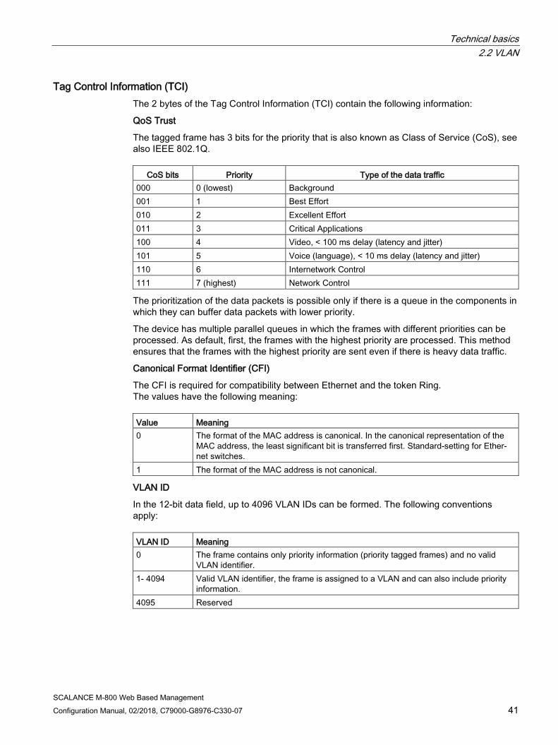
Tag Control Information (TCI) The 2 bytes of the Tag Control Information (TCI) contain the following information:
QoS Trust
The tagged frame has 3 bits for the priority that is also known as Class of Service (CoS), see also IEEE 802.1Q.
CoS bits Priority Type of the data traffic 000 0 (lowest) Background 001 1 Best Effort 010 2 Excellent Effort 011 3 Critical Applications 100 4 Video, < 100 ms delay (latency and jitter) 101 5 Voice (language), < 10 ms delay (latency and jitter) 110 6 Internetwork Control 111 7 (highest) Network Control
The prioritization of the data packets is possible only if there is a queue in the components in which they can buffer data packets with lower priority.
The device has multiple parallel queues in which the frames with different priorities can be processed. As default, first, the frames with the highest priority are processed. This method ensures that the frames with the highest priority are sent even if there is heavy data traffic.
Canonical Format Identifier (CFI)
The CFI is required for compatibility between Ethernet and the token Ring. The values have the following meaning: Value Meaning 0 The format of the MAC address is canonical. In the canonical representation of the
MAC address, the least significant bit is transferred first. Standard-setting for Ether-net switches.
1 The format of the MAC address is not canonical.
VLAN ID
In the 12-bit data field, up to 4096 VLAN IDs can be formed. The following conventions apply: VLAN ID Meaning 0 The frame contains only priority information (priority tagged frames) and no valid
VLAN identifier. 1- 4094 Valid VLAN identifier, the frame is assigned to a VLAN and can also include priority
information. 4095 Reserved

Technical basics 2.3 SNMP
SCALANCE M-800 Web Based Management 42 Configuration Manual, 02/2018, C79000-G8976-C330-07
2.3 SNMP
Introduction With the aid of the Simple Network Management Protocol (SNMP), you monitor and control network components from a central station, for example routers or switches. SNMP controls the communication between the monitored devices and the monitoring station.
Tasks of SNMP:
● Monitoring of network components
● Remote control and remote parameter assignment of network components
● Error detection and error notification
In versions v1 and v2c, SNMP has no security mechanisms. Each user in the network can access data and also change parameter assignments using suitable software.
For the simple control of access rights without security aspects, community strings are used.
The community string is transferred along with the query. If the community string is correct, the SNMP agent responds and sends the requested data. If the community string is not correct, the SNMP agent discards the query. Define different community strings for read and write permissions. The community strings are transferred in plain text.
Standard values of the community strings:
● public has only read permissions
● private has read and write permissions
Note
Because the SNMP community strings are used for access protection, do not use the standard values "public" or "private". Change these values following the initial commissioning.
Further simple protection mechanisms at the device level:
● Allowed Host The IP addresses of the monitoring systems are known to the monitored system.
● Read Only If you assign "Read Only" to a monitored device, monitoring stations can only read out data but cannot modify it.
SNMP data packets are not encrypted and can easily be read by others.
The central station is also known as the management station. An SNMP agent is installed on the devices to be monitored with which the management station exchanges data.
Technical basics 2.3 SNMP
SCALANCE M-800 Web Based Management Configuration Manual, 02/2018, C79000-G8976-C330-07 43
The management station sends data packets of the following type:
● GET Request for a data record from the SNMP agent
● GETNEXT Calls up the next data record.
● GETBULK (available as of SNMPv2c) Requests multiple data records at one time, for example several rows of a table.
● SET Contains parameter assignment data for the relevant device.
The SNMP agent sends data packets of the following type:
● RESPONSE The SNMP agent returns the data requested by the manager.
● TRAP If a certain event occurs, the SNMP agent itself sends traps.
SNMPv1/v2c/v3 use UDP (User Datagram Protocol) and use the UDP ports 161 and 162. The data is described in a Management Information Base (MIB).
SNMPv3 Compared with the previous versions SNMPv1 and SNMPv2c, SNMPv3 introduces an extensive security concept.
SNMPv3 supports:
● Fully encrypted user authentication
● Encryption of the entire data traffic
● Access control of the MIB objects at the user/group level
With the introduction of SNMPv3 you can no longer transfer user configurations to other devices without taking special action, e.g. by loading a configuration file or replacing the C-PLUG.
According to the standard, the SNMPv3 protocol uses a unique SNMP engine ID as an internal identifier for an SNMP agent. This ID must be unique in the network. It is used to authenticate access data of SNMPv3 users and to encrypt it.
Depending on whether you have enabled or disabled the “SNMPv3 User Migration” function, the SNMP engine ID is generated differently.
Restriction when using the function
Use the "SNMPv3 User Migration" function only to transfer configured SNMPv3 users to a substitute device when replacing a device. Do not use the function to transfer configured SNMPv3 users to multiple devices. If you load a configuration with created SNMPv3 users on several devices, these devices use the same SNMP engine ID. If you use these devices in the same network, your configuration contradicts the SNMP standard.

Technical basics 2.4 ICMP
SCALANCE M-800 Web Based Management 44 Configuration Manual, 02/2018, C79000-G8976-C330-07
Compatibility with predecessor products
You can only transfer SNMPv3 users to a different device if you have created the users as migratable users. To create a migratable user the "SNMPv3 User Migration" function must be activated when you create the user.
2.4 ICMP The acronym ICMP stands for Internet Control Message Protocol (RFC792) and is used to exchange error and information messages.
● Error message
Informs the sender of the IP frame that when forwarding the frame an error or a parameter problem occurred.
● Information message
Can contain information about the time measurement, the address mask, the reachability of the destination or for finding the router.
Structure of the ICMP data packet 0 4 8 12 16 20 24 28 31 ICMP packet type Type of message
Code Further details of the message
Checksum
Data (optional)
● ICMP packet type
The most important ICMP packet types are as follows:
– Redirect
The router informs the host in one of its subnets that there is a better route to the destination. This ICMP packet type is dealt with in more detail in the following description.
– Destination Unreachable
IP frame cannot be delivered.
– Time Exceeded
Time limit exceeded
– Echo-Request
Echo request, better known as ping.
● Code
The code describes the ICMP packet type in greater detail. The selection depends on the selected ICMP packet type. With "Destination Unreachable,", for example "Code 1" host cannot be reached.
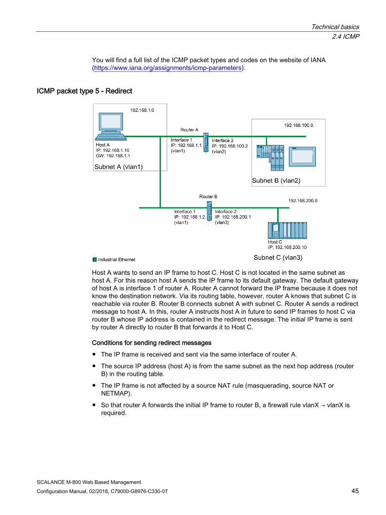
Technical basics 2.4 ICMP
SCALANCE M-800 Web Based Management Configuration Manual, 02/2018, C79000-G8976-C330-07 45
You will find a full list of the ICMP packet types and codes on the website of IANA (https://www.iana.org/assignments/icmp-parameters).
ICMP packet type 5 - Redirect
Host A wants to send an IP frame to host C. Host C is not located in the same subnet as host A. For this reason host A sends the IP frame to its default gateway. The default gateway of host A is interface 1 of router A. Router A cannot forward the IP frame because it does not know the destination network. Via its routing table, however, router A knows that subnet C is reachable via router B. Router B connects subnet A with subnet C. Router A sends a redirect message to host A. In this, router A instructs host A in future to send IP frames to host C via router B whose IP address is contained in the redirect message. The initial IP frame is sent by router A directly to router B that forwards it to Host C.
Conditions for sending redirect messages
● The IP frame is received and sent via the same interface of router A.
● The source IP address (host A) is from the same subnet as the next hop address (router B) in the routing table.
● The IP frame is not affected by a source NAT rule (masquerading, source NAT or NETMAP).
● So that router A forwards the initial IP frame to router B, a firewall rule vlanX → vlanX is required.
Technical basics 2.5 Security functions
SCALANCE M-800 Web Based Management 46 Configuration Manual, 02/2018, C79000-G8976-C330-07
2.5 Security functions
2.5.1 User management
Overview of user management Access to the device is managed by configurable user settings. Set up users with a password for authentication. Assign a role with suitable rights to the users.
The authentication of users can either be performed locally by the device or by an external RADIUS server. You configure how the authentication is handled on the "Security > AAA > General" page.
Local logon The local logging on of users by the device runs as follows:
1. The user logs on with user name and password on the device.
2. The device checks whether an entry exists for the user.
→ If an entry exists, the user is logged in with the rights of the associated role.
→ If no corresponding entry exists, the user is denied access.
Login via an external RADIUS server RADIUS (Remote Authentication Dial-In User Service) is a protocol for authenticating and authorizing users by servers on which user data can be stored centrally.
Depending on the RADIUS authorization mode you have selected on the "Security > AAA > RADIUS Client" page, the device evaluates different information of the RADIUS server.

Technical basics 2.5 Security functions
SCALANCE M-800 Web Based Management Configuration Manual, 02/2018, C79000-G8976-C330-07 47
RADIUS authorization mode "Standard"
If you have set the authorization mode "conventional", the authentication of users via a RADIUS server runs as follows:
1. The user logs on with user name and password on the device.
2. The device sends an authentication request with the login data to the RADIUS server.
3. The RADIUS server runs a check and signals the result back to the device.
– The RADIUS server reports a successful authentication and returns the value "Administrative User" to the device for the attribute "Service Type".
→ The user is logged in with administrator rights.
– The RADIUS server reports a successful authentication and returns a different or even no value to the device for the attribute "Service Type".
→ The user is logged in with read rights.
– The RADIUS server reports a failed authentication to the device:
→ The user is denied access.
RADIUS authorization mode "SiemensVSA"
Requirement
For the RADIUS authorization mode "Siemens VSA" the following needs to be set on the RADIUS server:
● Manufacturer code: 4196
● Attribute number: 1
● Attribute format: Character string (group name)
Technical basics 2.5 Security functions
SCALANCE M-800 Web Based Management 48 Configuration Manual, 02/2018, C79000-G8976-C330-07
Procedure
If you have set the authorization mode "SiemensVSA", the authentication of users via a RADIUS server runs as follows:
1. The user logs on with user name and password on the device.
2. The device sends an authentication request with the login data to the RADIUS server.
3. The RADIUS server runs a check and signals the result back to the device.
Case A: The RADIUS server reports a successful authentication and returns the group assigned to the user to the device.
– The group is known on the device and the user is not entered in the table "External User Accounts"
→ The user is logged in with the rights of the assigned group.
– The group is known on the device and the user is entered in the table "External User Accounts"
→ The user is assigned the role with the higher rights and logged in with these rights.
– The group is not known on the device and the user is entered in the table "External User Accounts"
→ The user is logged in with the rights of the role linked to the user account.
– The group is not known on the device and the user is not entered in the table "External User Accounts"
→ The user is logged in with the rights of the role "Default".
Case B: The RADIUS server reports a successful authentication but does not return a group to the device.
– The user is entered in the table "External User Accounts":
→ The user is logged in with the rights of the linked role "".
– The user is not entered in the table "External User Accounts":
→ The user is logged in with the rights of the role "Default".
Case C: The RADIUS server reports a failed authentication to the device:
– The user is denied access.
2.5.2 Firewall The security functions of the device include a stateful inspection firewall. This is a method of packet filtering or packet checking.
The IP packets are checked based on firewall rules in which the following is specified:
● The permitted protocols
● IP addresses and ports of the permitted sources
● IP addresses and ports of the permitted destinations
Technical basics 2.5 Security functions
SCALANCE M-800 Web Based Management Configuration Manual, 02/2018, C79000-G8976-C330-07 49
If an IP packet fits the specified parameters, it is allowed to pass through the firewall. The rules also specify what is done with IP packets that are not allowed to pass through the firewall.
Simple packet filter techniques require two firewall rules per connection.
● One rule for the query direction from the source to the destination.
● A second rule for the response direction from the destination to the source
Stateful inspection firewall You only need to specify one firewall rule for the query direction from the source to the destination. The second rule is added implicitly. The packet filter recognizes when, for example, computer "A" is communicating with computer "B" and only then does it allow replies. A query by computer "B" is therefore not possible without a prior request by computer "A".
You configure the firewall in "Security > Firewall (Page 308)".
Note IP packets via layer 2 (within the same VLAN)
If the IP packets from the device are sent via a switch port (layer 2), these IP packets are not checked based on firewall rules. The firewall has no effect on packets forwarded at the layer 2 level.
Communication directions from to Meaning vlan x vlan x Access from IP subnet vlan x and the device to IP subnet
vlan x. Example: vlan1 (INT) → vlan2 (EXT) Access from the local IP subnet and the device to the external IP subnet.
ppp0/usb Access from the IP subnet to the mobile wireless interface of the device.
Device Access from the IP subnet to the device. SINEMA RC Access from the IP subnet and the device to the SINEMA
RC connection. IPsec (all) IPsec <Connection Name> OpenVPN (all) OpenVPN <Connection Name>
Access from the IP subnet to the tunnel partners that can be reached via all VPN connections (all) or via a certain VPN connection (<Connection Name>).
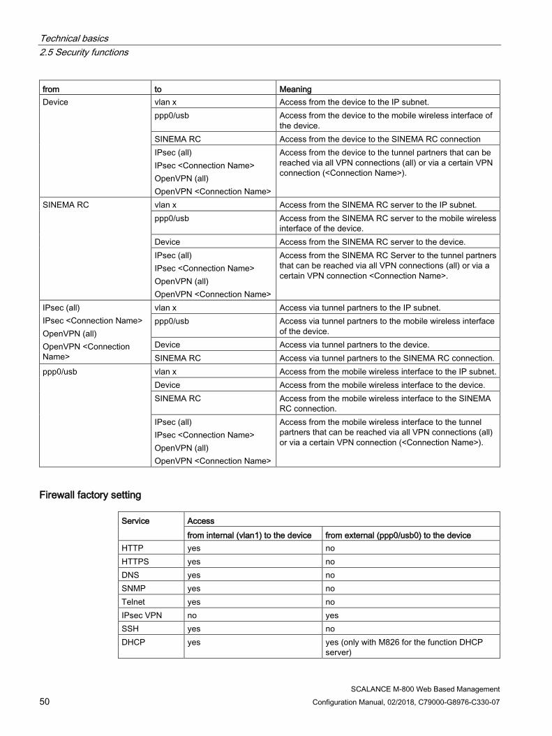
Technical basics 2.5 Security functions
SCALANCE M-800 Web Based Management 50 Configuration Manual, 02/2018, C79000-G8976-C330-07
from to Meaning Device vlan x Access from the device to the IP subnet.
ppp0/usb Access from the device to the mobile wireless interface of the device.
SINEMA RC Access from the device to the SINEMA RC connection IPsec (all) IPsec <Connection Name> OpenVPN (all) OpenVPN <Connection Name>
Access from the device to the tunnel partners that can be reached via all VPN connections (all) or via a certain VPN connection (<Connection Name>).
SINEMA RC vlan x Access from the SINEMA RC server to the IP subnet. ppp0/usb Access from the SINEMA RC server to the mobile wireless
interface of the device. Device Access from the SINEMA RC server to the device. IPsec (all) IPsec <Connection Name> OpenVPN (all) OpenVPN <Connection Name>
Access from the SINEMA RC Server to the tunnel partners that can be reached via all VPN connections (all) or via a certain VPN connection <Connection Name>.
IPsec (all) IPsec <Connection Name> OpenVPN (all) OpenVPN <Connection Name>
vlan x Access via tunnel partners to the IP subnet. ppp0/usb Access via tunnel partners to the mobile wireless interface
of the device. Device Access via tunnel partners to the device. SINEMA RC Access via tunnel partners to the SINEMA RC connection.
ppp0/usb vlan x Access from the mobile wireless interface to the IP subnet. Device Access from the mobile wireless interface to the device. SINEMA RC Access from the mobile wireless interface to the SINEMA
RC connection. IPsec (all) IPsec <Connection Name> OpenVPN (all) OpenVPN <Connection Name>
Access from the mobile wireless interface to the tunnel partners that can be reached via all VPN connections (all) or via a certain VPN connection (<Connection Name>).
Firewall factory setting Service
Access from internal (vlan1) to the device from external (ppp0/usb0) to the device
HTTP yes no HTTPS yes no DNS yes no SNMP yes no Telnet yes no IPsec VPN no yes SSH yes no DHCP yes yes (only with M826 for the function DHCP
server)
Technical basics 2.5 Security functions
SCALANCE M-800 Web Based Management Configuration Manual, 02/2018, C79000-G8976-C330-07 51
Service
Access from internal (vlan1) to the device from external (ppp0/usb0) to the device
Ping yes no System time no no SMS relay (only with M87x)
yes no
2.5.3 NAT NAT (Network Address Translation) is a method of translating IP addresses in data packets. With this, two different networks (internal and external) can be connected together.
A distinction is made between source NAT in which the source IP address is translated and destination NAT in which the destination IP address is translated.
You will find information on NAT scenarios that are implemented with the device at the following address: (https://support.industry.siemens.com/cs/gb/en/view/109744660)
IP masquerading IP masquerading is a simplified source NAT. With each outgoing data packet sent via this interface, the source IP address is replaced by the IP address of the interface. The adapted data packet is sent to the destination IP address. For the destination host it appears as if the queries always came from the same sender. The internal nodes cannot be reached directly from the external network. By using NAPT, the services of the internal nodes can be made reachable via the external IP address of the device.
IP masquerading can be used if the internal IP addresses cannot or should not be forwarded externally, for example because the internal network structure should remain hidden.
You configure masquerading in "Layer 3" > "NAT" > "IP Masquerading (Page 275)".
NAPT NAPT (Network Address and Port Translation) is a form of destination NAT and is often called port forwarding. This allows the services of the internal nodes to be reached from external that are hidden by IP masquerading or source NAT.
Incoming data packets are translated that come from the external network and are intended for an external IP address of the device (destination IP address). The destination IP address is replaced by the IP address of the internal node. In addition to address translation, port translation is also possible.

Technical basics 2.5 Security functions
SCALANCE M-800 Web Based Management 52 Configuration Manual, 02/2018, C79000-G8976-C330-07
The options are available for port translation: from to Response a single port the same port If the ports are the same, the frames will be forwarded without port
translation. a single port a single port The frames are translated to the port. a port range a single port The frames from the port range are translated to the same port
(n:1). a port range the same port
range If the port ranges are the same, the frames will be forwarded with-out port translation.
a port range another port range
The frames are translated to any free port from the target range. With individual connection, they are normally translated to the first port in the target range. If there are connections at the same time, the round robin method is used to translate to a free port in the target range.
a single port a port range The frames are translated to any free port from the target range. With individual connection, they are normally translated to the first port in the target range. If there are connections at the same time, the round robin method is used to translate to a free port in the target range.
Port forwarding can be used to allow external nodes access to certain services of the internal network e.g. FTP, HTTP.
You configure NAPT in "Layer 3" > "NAT" > "NAPT (Page 276)".
Source NAT As in masquerading, in source NAT the source address is translated. In addition to this, the outgoing data packets can be restricted. These include limitation to certain IP addresses or IP address ranges and limitation to certain interfaces.
Source NAT can be used if the internal IP addresses cannot or should not be forwarded externally, for example because a private address range such as 192.168.x.x is used.
You configure source NAT in "Layer 3" > "NAT" > "Source NAT (Page 278)".
NETMAP With NETMAP it is possible to translate complex subnets to a different subnet. In this translation, the subnet part of the IP address is changed and the host part remains. For translation with NETMAP only one rule is required. NETMAP can translate both the source IP address and the destination IP address. To perform the translation with destination NAT and source NAT, numerous rules would be necessary. NETMAP can also be applied to VPN connections.
You configure NETMAP in "Layer 3" > "NAT" > "NETMAP (Page 280)".
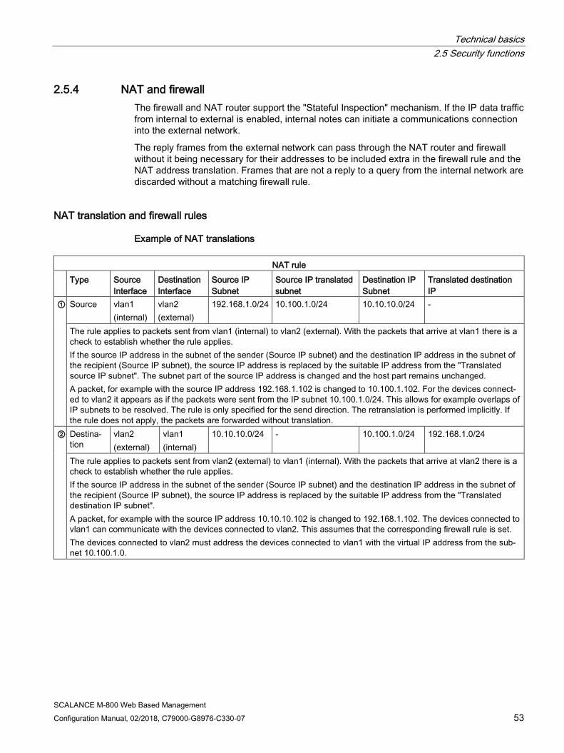
Technical basics 2.5 Security functions
SCALANCE M-800 Web Based Management Configuration Manual, 02/2018, C79000-G8976-C330-07 53
2.5.4 NAT and firewall The firewall and NAT router support the "Stateful Inspection" mechanism. If the IP data traffic from internal to external is enabled, internal notes can initiate a communications connection into the external network.
The reply frames from the external network can pass through the NAT router and firewall without it being necessary for their addresses to be included extra in the firewall rule and the NAT address translation. Frames that are not a reply to a query from the internal network are discarded without a matching firewall rule.
NAT translation and firewall rules
Example of NAT translations
NAT rule Type Source
Interface Destination Interface
Source IP Subnet
Source IP translated subnet
Destination IP Subnet
Translated destination IP
①
Source vlan1 (internal)
vlan2 (external)
192.168.1.0/24 10.100.1.0/24 10.10.10.0/24 -
The rule applies to packets sent from vlan1 (internal) to vlan2 (external). With the packets that arrive at vlan1 there is a check to establish whether the rule applies. If the source IP address in the subnet of the sender (Source IP subnet) and the destination IP address in the subnet of the recipient (Source IP subnet), the source IP address is replaced by the suitable IP address from the "Translated source IP subnet". The subnet part of the source IP address is changed and the host part remains unchanged. A packet, for example with the source IP address 192.168.1.102 is changed to 10.100.1.102. For the devices connect-ed to vlan2 it appears as if the packets were sent from the IP subnet 10.100.1.0/24. This allows for example overlaps of IP subnets to be resolved. The rule is only specified for the send direction. The retranslation is performed implicitly. If the rule does not apply, the packets are forwarded without translation.
② Destina-tion
vlan2 (external)
vlan1 (internal)
10.10.10.0/24 - 10.100.1.0/24 192.168.1.0/24
The rule applies to packets sent from vlan2 (external) to vlan1 (internal). With the packets that arrive at vlan2 there is a check to establish whether the rule applies. If the source IP address in the subnet of the sender (Source IP subnet) and the destination IP address in the subnet of the recipient (Source IP subnet), the source IP address is replaced by the suitable IP address from the "Translated destination IP subnet". A packet, for example with the source IP address 10.10.10.102 is changed to 192.168.1.102. The devices connected to vlan1 can communicate with the devices connected to vlan2. This assumes that the corresponding firewall rule is set. The devices connected to vlan2 must address the devices connected to vlan1 with the virtual IP address from the sub-net 10.100.1.0.

Technical basics 2.5 Security functions
SCALANCE M-800 Web Based Management 54 Configuration Manual, 02/2018, C79000-G8976-C330-07
Firewall rules for the NAT rules ① and ②
Example 1:
These IP packet filter rules allow the IP data traffic for all devices for the specified direction. NAT rule IP packet filter rules Description
Action From To Source (Range) Destination (Range)
Service
① Accept vlan1 (internal)
vlan2 (external)
192.168.1.0/24 (Source IP sub-net)
10.10.10.0/24 (Destination IP subnet)
all All packets sent from vlan1 (internal) to vlan2 (external) are allowed to pass. This IP packet filter rule applies to the devices connected to vlan1.
② Accept vlan2 (external)
vlan1 (internal)
192.168.1.0/24 (Translated des-tination IP)
10.100.1.0/24 (Destination IP subnet)
all All packets sent from vlan2 (external) to vlan1 (internal) are allowed to pass.
Example 2:
These IP packet filter rules restrict the IP data traffic to a specific device. NAT rule IP packet filter rules Description
Action From To Source (Range) Destination (Range)
Service
① Accept vlan1 (internal)
vlan2 (external)
192.168.1.20/32 (Source IP sub-net)
10.10.10.0/24 (Destination IP subnet)
all Only packets sent to vlan2 (external) from the IP address 192.168.1.20 are allowed to pass.
② Accept vlan2 (external)
vlan1 (internal)
192.168.1.20/32 (Translated des-tination IP sub-net)
10.100.1.0/24 (Destination IP subnet)
all Only packets sent from vlan2 (external) to the IP address 192.168.1.20 are allowed to pass.

Technical basics 2.5 Security functions
SCALANCE M-800 Web Based Management Configuration Manual, 02/2018, C79000-G8976-C330-07 55
2.5.5 Certificates
Certificate types The device uses different certificates to authenticate the various nodes.
Certificate Is used in... CA certificate The CA certificate is a certificate issued by a Certificate Authority from
which the server, device and partner certificates are derived. To allow a certificate to be derived, the CA certificate has a private key signed by the certificate authority. The key exchange between the device and the VPN gateway of the partner takes place automatically when establishing the connection. No manual exchange of key files is necessary.
IPsec VPN (Page 316)
Server certificate
Server certificates are required to establish secure communication (e.g. HTTPS, VPN...) between the device and another network participant. The server certificate is an encrypted SSL certificate. The server certificate is derived from the oldest valid CA, even if this is "out of service". The crucial thing is the validity date of the CA.
SINEMA RC (Page 231)
Device certificate Certificates with the private key (key file) with which the device identifies itself.
IPsec VPN (Page 316)
Partner certificate Certificates with which the VPN gateway of the partner identifies itself with the device.
IPsec VPN (Page 316)
File types File type Description *.crt File that contains the certificate. *.p12 In the PKCS12 certificate file, the private key is stored with the corresponding certif-
icate and is password protected. The CA creates a certificate file (PKCS12) for both ends of a VPN connection with the file extension ".p12". This certificate file contains the public and private key of the local station, the signed certificate of the CA and the public key of the CA.
*.pem Certificate and key as Base64-coded ASCII text.
2.5.6 VPN The device supports the following VPN systems
● IPsec VPN
● OpenVPN
Technical basics 2.5 Security functions
SCALANCE M-800 Web Based Management 56 Configuration Manual, 02/2018, C79000-G8976-C330-07
2.5.6.1 IPsec VPN You configure the IPsec connections in "Security" > " IPsec VPN (Page 316)".
With IPsec VPN, the frames are transferred in tunnel mode. To allow the device to establish a VPN tunnel, the remote network must have a VPN gateway as the partner.
For the VPN connections, the device distinguishes two modes:
● Roadwarrior mode
In this mode either the address of the partner is fixed or an IP range is entered from which the connections are taken. The device learns the reachable remote subnets from the partner.
● Standard mode
In this mode the address of the partner or the remote subnet is entered permanently. The device can either establish the connection actively as a VPN client or wait passively for connection establishment by the partner.
The IPsec method The device uses the IPsec method in the tunnel mode for the VPN tunnel. Here, the frames to be transferred are completely encrypted and provided with a new header before they are sent to the VPN gateway of the partner. The frames received by the partner are decrypted and forwarded to the recipient.
To provide security, the IPsec protocol suite uses various protocols:
● The IP Authentication Header (AH) handles the authentication and identification of the source.
● The Encapsulation Security Payload (ESP) encrypts the data.
● The Security Association (SA) contains the specifications negotiated between the partners, e.g. about the lifetime of the key, the encryption algorithm, the period for new authentication etc.
● Internet Key Exchange (IKE) is a key exchange method. The key exchange takes place in two phases:
– Phase 1
In this phase, no security services such as encryption, authentication and integrity checks are available yet since the required keys and the IPsec SA still need to be created. Phase 1 serves to establish a secure VPN tunnel for phase 2. To achieve this, the communications partners negotiate an ISAKMP Security Association (ISAKMP SA) that defines the required security services (algorithms, authentication methods used). The subsequent messages and phase 2 are therefore secure.
– Phase 2
Phase 2 serves to negotiate the required IPsec SA. Similar to phase 1, exchanging offers achieves agreement about the authentication methods, the algorithms and the encryption method to protect the IP packets with IPsec AH and IPsec ESP.
The exchange of messages is protected by the ISAKMP SA negotiated in phase 1. Due to the ISAKMP SA negotiated in phase 1, the identity of the nodes is known and the method for the integrity check already exists.
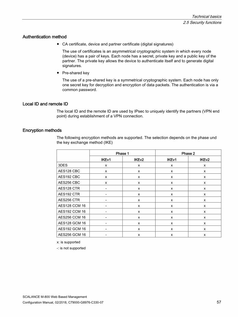
Technical basics 2.5 Security functions
SCALANCE M-800 Web Based Management Configuration Manual, 02/2018, C79000-G8976-C330-07 57
Authentication method ● CA certificate, device and partner certificate (digital signatures)
The use of certificates is an asymmetrical cryptographic system in which every node (device) has a pair of keys. Each node has a secret, private key and a public key of the partner. The private key allows the device to authenticate itself and to generate digital signatures.
● Pre-shared key
The use of a pre-shared key is a symmetrical cryptographic system. Each node has only one secret key for decryption and encryption of data packets. The authentication is via a common password.
Local ID and remote ID The local ID and the remote ID are used by IPsec to uniquely identify the partners (VPN end point) during establishment of a VPN connection.
Encryption methods The following encryption methods are supported. The selection depends on the phase und the key exchange method (IKE) Phase 1 Phase 2
IKEv1 IKEv2 IKEv1 IKEv2 3DES x x x x AES128 CBC x x x x AES192 CBC x x x x AES256 CBC x x x x AES128 CTR - x x x AES192 CTR - x x x AES256 CTR - x x x AES128 CCM 16 - x x x AES192 CCM 16 - x x x AES256 CCM 16 - x x x AES128 GCM 16 - x x x AES192 GCM 16 - x x x AES256 GCM 16 - x x x x: is supported
-: is not supported

Technical basics 2.5 Security functions
SCALANCE M-800 Web Based Management 58 Configuration Manual, 02/2018, C79000-G8976-C330-07
Default Ciphers During connection establishment a preset list can be transferred to the VPN connection partners. The list contains combinations of the three algorithms (Encryption, Authentication, Key Derivation). To establish a VPN connection, the VPN connection partner must support at least one of these combinations. The combinations depend on the phase und the key exchange method IKE).
Combination Phase 1 Phase 2
Encryption Authentica-tion
Key derivation IKEv1 IKEv2 IKEv1 IKEv2
AES128 SHA1 DH Group 14 x x x x AES256 SHA512 DH Group 16 x x x x AES128 CCM 16 SHA256 DH Group 14 - x x x AES256 CCM 16 SHA512 DH Group 16 - x x x AES128 SHA1 none - - x x AES256 SHA512 none - - x x AES128 CCM 16 SHA256 none - - x x AES256 CCM 16 SHA512 none - - x x x: Combination is part of the default cipher
-: Combination is not part of the default cipher none: For phase 2, no separate keys are exchanged. This means that Perfect Forward Secrecy (PFS) is disabled.
Requirements of the VPN partner The VPN partner must support IPsec with the following configuration to be able to establish an IPsec connection successfully:
● Authentication with partner certificate, CA certificates or pre-shared key
● IKEv1 or IKEv2
● Support of at least one of the following DH groups: Diffie-Hellman group 1, 2, 5 and 14 - 18
● 3DES or AES encryption
● MD5, SHA1, SHA256, SHA384 or SHA512
● Tunnel mode
If the VPN partner is downstream from a NAT router, the partner must support NAT-T. Or, the NAT router must know the IPsec protocol (IPsec/VPN passthrough).
NAT traversal (NAT-T) There may be a NAT router between the device and the VPN gateway of the remote network. Not all NAT routers allow IPsec frames to pass through. This means that it may be necessary to encapsulate the IPsec frames in UDP packets to be able to pass through the NAT router.

Technical basics 2.5 Security functions
SCALANCE M-800 Web Based Management Configuration Manual, 02/2018, C79000-G8976-C330-07 59
Dead peer detection This is only possible when the VPN partner supports DPD. DPD checks whether the connection is still operating problem free or whether there has been an interruption on the line. Without DPD and depending on the configuration, it may be necessary to wait until the SA lifetime has expired or the connection must be reinitiated manually. To check whether the IPsec connection is still problem-free, the device itself sends DPD queries to the VPN partner station. If the VPN partner station does not reply after a certain time has elapsed, the connection to the VPN partner station will be declared invalid. You configure the settings for DPD in phase 1.
2.5.6.2 OpenVPN With OpenVPN, virtual private networks (VPN) can be established. As an OpenVPN client, the device can establish a VPN connection to a remote network.
You configure the OpenVPN client in "Security" > " OpenVPN Client (Page 328)".
The VPN connection is established via virtual device drivers, the TAP and TUN device. During this, virtual network interfaces are created that act like a physical interface of the device and represent the endpoint of the VPN tunnel.
The device supports the following:
● TUN device: Routing mode
The LAN Interface and the virtual network interface are located in different IP subnets. The virtual tunnel interface is assigned a virtual IP address from a devised subnet by the OpenVPN server. The IP packets (layer 3) are routed between the virtual tunnel interface and the LAN interface.
Authentication method ● Certificates: CA certificate and device certificate
The use of certificates is an asymmetrical cryptographic system. Each node (device) has a secret, private key and a public key of the partner. The private key allows the device to authenticate itself and to generate digital signatures.
● User name / password
Access is restricted by a user name and a password.
Encryption methods The device also supports the following methods:
● BF CBC
● AES128 CBC
● AES192 CBC
● AES256 CBC
● DES EDE3

Technical basics 2.5 Security functions
SCALANCE M-800 Web Based Management 60 Configuration Manual, 02/2018, C79000-G8976-C330-07
2.5.6.3 VPN connection establishment The device supports the following options for establishing a VPN connection.
● OpenVPN: Security > OpenVPN > Connections (Page 329)
● IPsec VPN: Security > IPsec VPN > Connections (Page 319)
● SINEMA RC: System > SINEMA RC (Page 231)
Options Use Description
Open-VPN
IPsec VPN
SINEMA RC 1)
start x x - The device is "active", in other words, it attempts to establish a connection to a partner. The partner is ad-dressed using its configured WAN IP address or the configured FQDN.
wait - x - The device is "passive", in other words, it waits for the partner to initiate the connection.
on demand - x - The device attempts to establish a connection to a part-ner when necessary. The receipt of requests for VPN connection establishment is also possible. For the configured local and remote subnets, an entry is created in the routing table. If a node attempts to send data packets via the VPN tunnel from one of the net-works, the VPN connection is established. The settable timeout has the effect that after this time without any further data packets the VPN tunnel is terminated again.
start on DI x x - Connection establishment is controlled via the digital input (DI). wait on DI - x -
Digital input - - x Digital Input & Wake-up SMS
- - x Connection establishment is controlled via the digital input (DI) or SMS.
Wake-up SMS
- - x Connection establishment is controlled via SMS.
start on SMS x x - wait on SMS - x - Auto - - x The device adopts the settings of the SINEMA RC serv-
er. You configure the settings on the SINEMA IRC serv-er in "Remote connections > Devices". You will find further information on this topic in the operating instruc-tions "SINEMA RC Server".
Permanent - - x The device establishes a VPN connection to the SINEMA RC Server. The VPN tunnel is established permanently
1) KEY-PLUG SINEMA REMOTE CONNECT required

Technical basics 2.5 Security functions
SCALANCE M-800 Web Based Management Configuration Manual, 02/2018, C79000-G8976-C330-07 61
Digital input (DI) The establishment of the VPN tunnel can also be controlled via the digital input, e.g. using a button. When the button is closed, voltage is applied to the digital input and the LED of the digital input lights up. The lit LED indicates that signal 1 (TRUE / HIGH) is applied. Signal 1 triggers an event on the device with which the establishment of the VPN tunnel is controlled. You will find information on connecting and the maximum current load in the operating instructions of the devices.
Requirement
● In "System > Events > Configuration (Page 166)" for the "Digital Input" event "VPN Tunnel" is activated.
If this setting is not activated, the event is not passed on to the VPN connection.
Options
The device supports the following options for controlling the VPN tunnel via the digital input:
● start on DI
If the event "Digital Input" occurs, the device becomes "active". The device attempts to establish a VPN connection (OpenVPN, IPsec) to a partner.
● wait on DI
If the event "Digital Input" occurs, the device becomes "passive". The device waits for the partner to initiate the connection.
● Digital input
The settings of the SINEMA RC server are ignored. If the event "Digital In" occurs, the device becomes "active". The device attempts to establish a VPN connection to the SINEMA RC server.
● Digital Input & Wake-up SMS (only with M87x)
The settings of the SINEMA RC server are ignored. If the event "Digital In" occurs or the device receives a wake-up SMS message, the device becomes "active". The device attempts to establish a VPN connection to the SINEMA RC server.
Technical basics 2.5 Security functions
SCALANCE M-800 Web Based Management 62 Configuration Manual, 02/2018, C79000-G8976-C330-07
SMS (only with M87x): Requirement
● In "System > SMS > SMS Command (Page 210)" you specify who a command SMS of the class "System" will be accepted from.
● In "System > SMS > Event SMS " the function is activated and the telephone number of a recipient is configured.
● If this setting is not activated, the event is not passed on to the VPN connection.
Options
The device supports the following options for controlling the VPN tunnel via an SMS message:
● start on SMS
When the device receives a command SMS message, the device becomes "active". The command SMS message contains the name of the VPN connection (OpenVPN, IPsec). The device attempts to establish a connection to the partner specified in the VPN connection.
Format of the SMS message:
Establishment of the VPN connection:
– OpenVPN: SYS OVPN UP <name of the OpenVPN connection>, see Command SMS message (Page 343).
If you enter a "*" for <name of the OpenVPN connection>, the OpenVPN connections are established that are set in "Operation" "start on SMS".
– IPsec VPN: SYS IPSEC UP<name of the IPsec VPN connection>, see Command SMS message (Page 343).
If you enter a "*" for <name of the IPsec VPN connection>, the IPsec VPN connections are established that are set in "Operation" "start on SMS".
Termination of the VPN connection:
– OpenVPN: SYS OVPN DOWN <name of the OpenVPN connection>, see Command SMS message (Page 343).
If you enter a "*" for <name of the OpenVPN connection>, the OpenVPN connections are terminated that are set in "Operation" "start on SMS".
– IPsec VPN: SYS IPSEC DOWN<name of the IPsec VPN connection>, see Command SMS message (Page 343).
If you enter a "*" for <name of the IPsec VPN connection>, the IPsec VPN connections are terminated that are set in "Operation" "start on SMS".
● wait on SMS
When the device receives a command SMS message, the device is "passive". The command SMS message contains the name of the IPsec VPN connection. The device waits for the partner specified in the VPN connection to initiate the connection.

Technical basics 2.5 Security functions
SCALANCE M-800 Web Based Management Configuration Manual, 02/2018, C79000-G8976-C330-07 63
Format of the SMS message:
If you enter a "*" for <name of the IPsec VPN connection>, the IPsec VPN connections are established that are set in "Operation" "start on SMS".
– IPsec VPN: SYS IPSEC UP<name of the IPsec VPN connection>, see Command SMS message (Page 343).
If you enter a "*" for <name of the IPsec VPN connection>, the IPsec VPN connections are established that are set in "Operation" "start on SMS".
– IPsec VPN: SYS IPSEC DOWN<name of the IPsec VPN connection>, see Command SMS message (Page 343).
If you enter a "*" for <name of the IPsecVPN connection>, the IPsec VPN connections are terminated that are set in "Operation" "wait on SMS".
● Digital Input & Wake-up SMS
The settings of the SINEMA RC server are ignored. If the event "Digital In" occurs or the device receives a wake-up SMS message. The device attempts to establish a VPN connection to the SINEMA RC Server.
Format of the SMS message: SYS SRC UP <address of the SINEMA RC Server>, see Command SMS message (Page 343).
● Wake-up SMS
The settings of the SINEMA RC server are ignored. When the device receives a wake-up SMS message, it attempts to establish a VPN connection to the SINEMA RC Server.
Format of the SMS message:
– SYS SRC UP <address of the SINEMA RC Server>, see Command SMS message (Page 343).

Technical basics 2.5 Security functions
SCALANCE M-800 Web Based Management 64 Configuration Manual, 02/2018, C79000-G8976-C330-07
Notification options If the status of the digital input or a VPN tunnel (IPsec, OpenVPN, SINEMA RC) changes, the device provides several options for notification on the "Events (Page 166)" page.
Type of notification
Digital input
VPN tunnel Behavior if there is a status change
E-mail x x The device sends an e-mail. The e-mail contains the identification of the sending device, a description of the cause of the alarm in plain language, and a time stamp. Requirement: • An SMTP server is set up. • In "System > SMTP Client" the function is activated, a recipient and the IP
address of the SMTP server are configured.
Trap x x The device sends an SNMP trap. Requirement: • "SNMPv1 traps" is enabled in "System > Configuration". • In "System > Configuration > Traps" a recipient is configured to which the de-
vice sends the SNMP traps.
Log table x x The device writes an entry in the event log table. The content of the event log table is displayed in "Information > Log Table".
Syslog x x The device writes an entry to the Syslog server. Requirement: • A Syslog server has been set up. • In "System > Syslog Client" the function is activated and the IP address of the
Syslog server is configured.
Fault LED x - The fault LED lights up on the device. Digital input x x Controls the digital output or signals the status change with the "DO" LED.
A consumer can be connected to the digital output. You will find information on connecting in the operating instructions of the devices. The consumer signals a status change.
Note You can control the digital output directly via CLI or SNMP. In WBM and CLI, you can configure the use of the digital output in "Events". Do not control the digital output directly when you use this in the WBM and CLI.
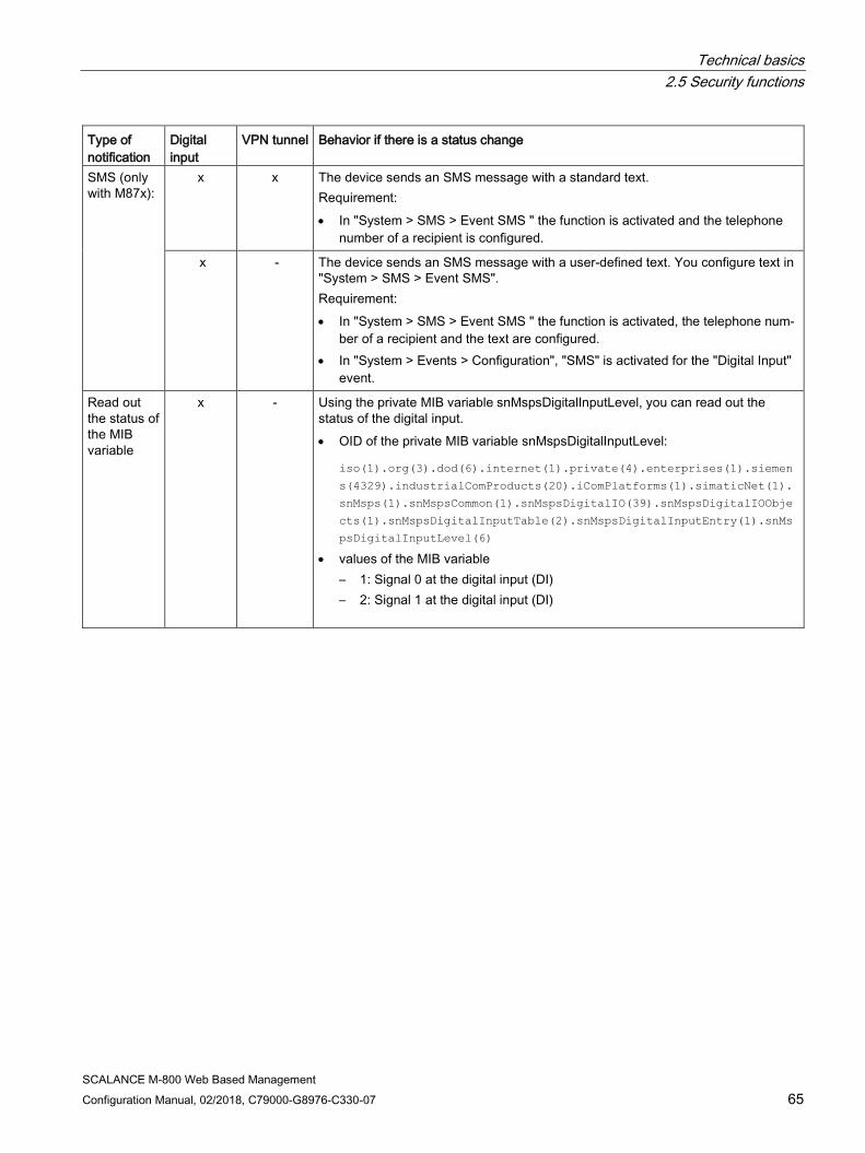
Technical basics 2.5 Security functions
SCALANCE M-800 Web Based Management Configuration Manual, 02/2018, C79000-G8976-C330-07 65
Type of notification
Digital input
VPN tunnel Behavior if there is a status change
SMS (only with M87x):
x x The device sends an SMS message with a standard text. Requirement: • In "System > SMS > Event SMS " the function is activated and the telephone
number of a recipient is configured.
x - The device sends an SMS message with a user-defined text. You configure text in "System > SMS > Event SMS". Requirement: • In "System > SMS > Event SMS " the function is activated, the telephone num-
ber of a recipient and the text are configured. • In "System > Events > Configuration", "SMS" is activated for the "Digital Input"
event.
Read out the status of the MIB variable
x - Using the private MIB variable snMspsDigitalInputLevel, you can read out the status of the digital input. • OID of the private MIB variable snMspsDigitalInputLevel:
iso(1).org(3).dod(6).internet(1).private(4).enterprises(1).siemen
s(4329).industrialComProducts(20).iComPlatforms(1).simaticNet(1).
snMsps(1).snMspsCommon(1).snMspsDigitalIO(39).snMspsDigitalIOObje
cts(1).snMspsDigitalInputTable(2).snMspsDigitalInputEntry(1).snMs
psDigitalInputLevel(6) • values of the MIB variable
– 1: Signal 0 at the digital input (DI) – 2: Signal 1 at the digital input (DI)
Technical basics 2.6 Redundancy
SCALANCE M-800 Web Based Management 66 Configuration Manual, 02/2018, C79000-G8976-C330-07
2.6 Redundancy
2.6.1 Spanning Tree
Avoiding loops on redundant connections The spanning tree algorithm allows network structures to be created in which there are several connections between two IE switches / bridges. Spanning tree prevents loops being formed in the network by allowing only one path and disabling the other (redundant) ports for data traffic. If there is an interruption, the data can be sent over an alternative path. The functionality of the spanning tree algorithm is based on the exchange of configuration and topology change frames.
Definition of the network topology using the configuration frames The devices exchange configuration frames known as BPDUs (Bridge Protocol Data Units) with each other to calculate the topology. The root bridge is selected and the network topology created using these frames. BPDUs also bring about the status change of the root ports.
The root bridge is the bridge that controls the spanning tree algorithm for all involved components.
Once the root bridge has been specified, each device sets a root port. The root port is the port with the lowest path costs to the root bridge.
Response to changes in the network topology If nodes are added to a network or drop out of the network, this can affect the optimum path selection for data packets. To be able to respond to such changes, the root bridge sends configuration messages at regular intervals. The interval between two configuration messages can be set with the "Hello Time" parameter.
Keeping configuration information up to date With the "Max Age" parameter, you set the maximum age of configuration information. If a bridge has information that is older than the time set in "Max Age", it discards the message and initiates recalculation of the paths.
New configuration data is not used immediately by a bridge but only after the period specified in the "Forward Delay" parameter. This ensures that operation is only started with the new topology after all the bridges have the required information.
Technical basics 2.6 Redundancy
SCALANCE M-800 Web Based Management Configuration Manual, 02/2018, C79000-G8976-C330-07 67
2.6.1.1 RSTP
Rapid Spanning Tree Protocol (RSTP) One disadvantage of STP is that if there is a disruption or a device fails, the network needs to reconfigure itself: The devices start to negotiate new paths only when the interruption occurs. This can take up to 30 seconds. For this reason, STP was expanded to create the "Rapid Spanning Tree Protocol" (RSTP, IEEE 802.1w). This differs from STP essentially in that the devices are already collecting information about alternative routes during normal operation and do not need to gather this information after a disruption has occurred. This means that the reconfiguration time for an RSTP controlled network can be reduced to a few seconds. This is achieved by using the following functions:
● Edge ports (end node port) Edge ports are ports connected to an end device. A port that is defined as an edge port is activated immediately after connection establishment. If a spanning tree BPDU is received at an edge port, the port loses its role as edge port and it takes part in (R)STP again. If no further BPDU is received after a certain time has elapsed (3 x hello time), the port returns to the edge port status.
● Point-to-point (direct communication between two neighboring devices) By directly linking the devices, a status change (reconfiguration of the ports) can be made without any delays.
● Alternate port (substitute for the root port) A substitute for the root port is configured. If the connection to the root bridge is lost, the device can establish a connection over the alternate port without any delay due to reconfiguration.
● Reaction to events Rapid spanning tree reacts to events, for example an aborted connection, without delay. There is no waiting for timers as in spanning tree.
● Counter for the maximum bridge hops The number of bridge hops a package is allowed to make before it automatically becomes invalid.
In principle, therefore with rapid spanning tree, alternatives for many parameters are preconfigured and certain properties of the network structure taken into account to reduce the reconfiguration time.

Technical basics 2.6 Redundancy
SCALANCE M-800 Web Based Management 68 Configuration Manual, 02/2018, C79000-G8976-C330-07
2.6.2 VRRPv3
Router redundancy with VRRPv3 With the Virtual Router Redundancy Protocol v3 (VRRPv3), the failure of a router in a network can be countered. Version 3 of VRRP (RFC 5798) is based on version 2 (RFC 5798).
VRRP can only be used with virtual IP interfaces (VLAN interfaces).
Several VRRP routers in a network segment are put together as a logical group representing a virtual router (VR). The group is defined using the virtual ID (VRID). Within the group, the VRID must be the same. The VRID can no longer be used for other groups.
The virtual router is assigned a virtual IP address and a virtual MAC address. One of the VRRP routers within the group is specified as the master router. The master router has priority 255. The other VRRP routers are backup routers. The master router assigns the virtual IP address and the virtual MAC address to its network interface. The master router sends VRRP packets (advertisements) to the backup routers at specific intervals. With the VRRP packets, the master router signals that it is still functioning. The master router also replies to the ARP queries.
If the virtual master router fails, a backup router takes over the role of the master router. The backup router with the highest priority becomes the master router. If the priority of the backup routers is the same, the higher MAC address decides. The backup router becomes the new virtual master router.
The new virtual master router adopts the virtual MAC and IP address. This means that no routing tables or ARP tables need to be updated. The consequences of a device failure are therefore minimized.
You configure VRRP in "Layer 3 > VRRPv3 (Page 282)".
SCALANCE M-800 Web Based Management Configuration Manual, 02/2018, C79000-G8976-C330-07 69
Security recommendation 3
To prevent unauthorized access, note the following security recommendations.
A checklist supports you in setting up your device. You can find the checklist at the following address: (https://support.industry.siemens.com/cs/ww/en/view/109745536)
General ● You should make regular checks to make sure that the device meets these
recommendations and/or other security guidelines.
● Evaluate your plant as a whole in terms of security. Use a cell protection concept with suitable products:
Link: (https://www.industry.siemens.com/topics/global/en/industrial-security/pages/default.aspx)
● When the internal and external network are disconnected, an attacker cannot access internal data from the outside. Therefore operate the device only within a protected network area.
● Use VPN to encrypt and authenticate communication from and to the devices.
● For data transmission via a non-secure network use an encrypted VPN tunnel (IPsec, Open VPN).
● Separate connections correctly (WBM. Telnet, SSH etc.).
Physical access ● Limit physical access to the device to qualified personnel.
The memory card or the PLUG (C-PLUG, KEY-PLUG) contains sensitive data such as certificates, keys etc. that can be read out and modified.
● Lock unused physical ports on the device. Unused ports can be used to gain forbidden access to the plant.

Security recommendation
SCALANCE M-800 Web Based Management 70 Configuration Manual, 02/2018, C79000-G8976-C330-07
Software (security functions) ● Keep the software up to date. Check regularly for security updates of the product.
You will find information on this on the Internet pages "Industrial Security (https://www.siemens.com/industrialsecurity)".
● Inform yourself regularly about security advisories and bulletins published by Siemens ProductCERT (https://www.siemens.com/cert/en/cert-security-advisories.htm).
● Only activate protocols that you really require to use the device.
● Restrict access to the management of the device with rules in an access control list (ACL) or rules in the firewall.
● The option of VLAN structuring provides good protection against DoS attacks and unauthorized access. Check whether this is practical or useful in your environment.
● Use a central logging server to log changes and accesses. Operate your logging server within the protected network area and check the logging information regularly.
Passwords ● Define rules for the use of devices and assignment of passwords.
● Regularly update passwords and keys to increase security.
● Change all default passwords for users before you operate the device.
● Only use passwords with a high password strength. Avoid weak passwords for example password1, 123456789, abcdefgh.
● Make sure that all passwords are protected and inaccessible to unauthorized personnel.
● Do not use the same password for different users and systems or after it has expired.
Keys and certificates This section deals with the security keys and certificates you require to set up TLS, VPN (IPsec, OpenVPN) and SINEMA RC.
● The device contains a pre-installed X.509 certificate with key. Replace this certificate with a self-made certificate with key. We recommend that you use a certificate signed by a reliable external or internal certification authority.
● Use the certification authority including key revocation and management to sign the certificates.
● Make sure that user-defined private keys are protected and inaccessible to unauthorized persons.
● Verify certificates and fingerprints on the server and client to prevent "man in the middle" attacks.
● It is recommended that you use password-protected certificates in the PKCS #12 format
● It is recommended that you use certificates with a key length of at least 2048 bits.
● Change keys and certificates immediately, if there is a suspicion of compromise.
Security recommendation
SCALANCE M-800 Web Based Management Configuration Manual, 02/2018, C79000-G8976-C330-07 71
Secure/non-secure protocols ● Avoid or disable non-secure protocols, for example Telnet and TFTP. For historical
reasons, these protocols are still available, however not intended for secure applications. Use non-secure protocols on the device with caution.
● Avoid or disable non-secure protocols. Check whether use of the following protocols is necessary:
– Broadcast pings
– Non authenticated and unencrypted interfaces
– ICMP (redirect)
– LLDP
– Syslog
– DHCP Options 66/67
– TFTP
● The following protocols provide secure alternatives:
– SNMPv1/v2 → SNMPv3
Check whether use of SNMPv1 is necessary. SNMPv1 is classified as non-secure. Use the option of preventing write access. The product provides you with suitable setting options.
If SNMP is enabled, change the community names. If no unrestricted access is necessary, restrict access with SNMP.
– HTTP → HTTPS
– Telnet → SSH
– TFTP → SFTP
● Use secure protocols when access to the device is not prevented by physical protection measures.
● To prevent unauthorized access to the device or network, take suitable protective measures against non-secure protocols.
● If you require non-secure protocols and services, activate these at interfaces that are located within a protected network area.
● Using a firewall, restrict the services and protocols available to the outside to a minimum.
● For the DCP function, enable the "DCP read-only" mode after commissioning.

Security recommendation
SCALANCE M-800 Web Based Management 72 Configuration Manual, 02/2018, C79000-G8976-C330-07
Available protocols per port The following list provides you with an overview of the open ports on this device. Keep this in mind when configuring a firewall.
With some protocols the port can be open but access is prevented by a predefined IP package filter rule. You will find further information on the predefined IP package rules in "Security > Firewall > Predefined IPv4 rules".
The table includes the following columns:
● Protocol
All protocols that the device supports
● Port number
Port number assigned to the protocol
● Port status
– Open
The port is always open and cannot be closed.
– Open (when configured)
The port is open if it has been configured.
● Internal / external interface
Specifies the status of the port in the delivery state (factory setting) at the interface. Possible status: Open, closed
● Authentication
Specifies whether or not the protocol is authenticated during access.
● Encryption
Specifies whether or not the transfer is encrypted. Protocol Port number Port status Factory setting Authentication Encryption
Internal interface
External interface
SSH SFTP
TCP/22 Open (when configured)
Open Closed Yes Yes
HTTP TCP/80 Open (when configured)
Open Closed Yes No
HTTPS TCP/443 Open Open Closed Yes Yes SNTP UDP/123 Open
(only outgoing) Closed Closed No No
SNMP UDP/161 Open (when configured)
Open Closed Yes Yes (when configured)
DNS TCP/53 Open (when configured)
Open Closed No No
UDP/53 Open (when configured)
Open Closed No No
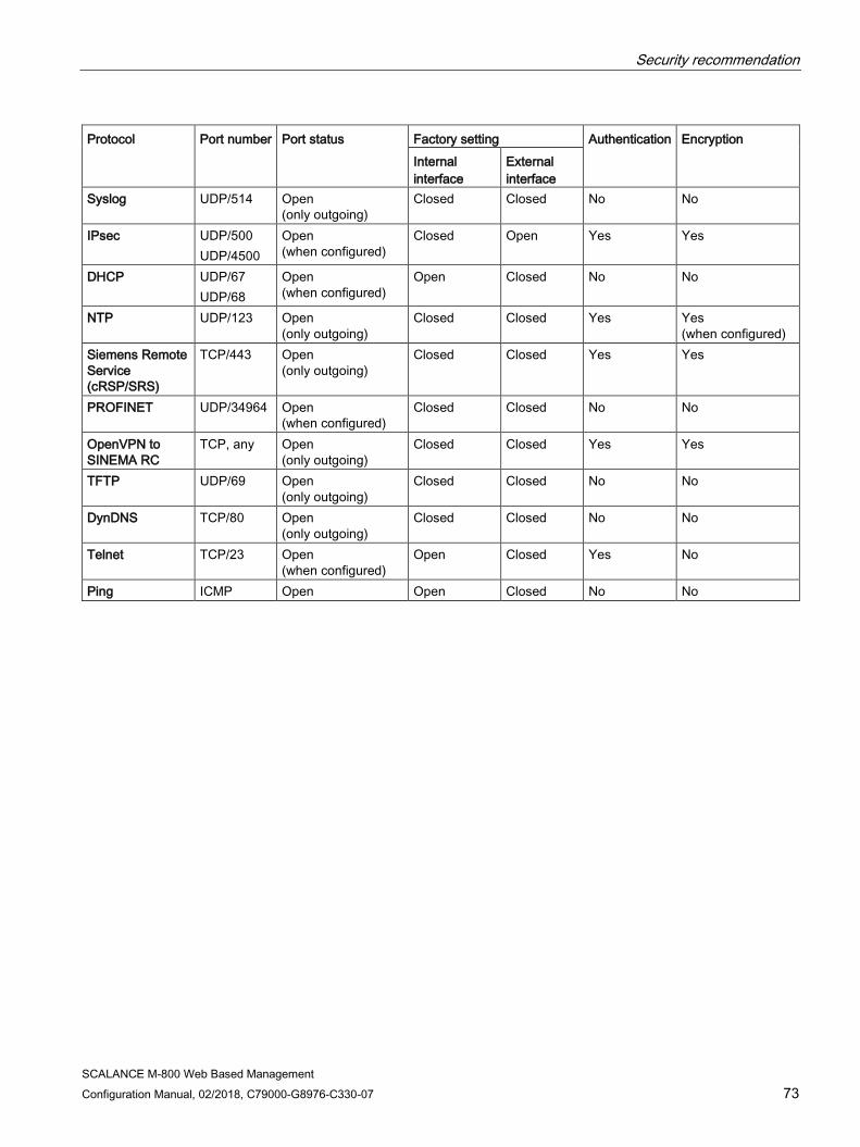
Security recommendation
SCALANCE M-800 Web Based Management Configuration Manual, 02/2018, C79000-G8976-C330-07 73
Protocol Port number Port status Factory setting Authentication Encryption Internal interface
External interface
Syslog UDP/514 Open (only outgoing)
Closed Closed No No
IPsec UDP/500 UDP/4500
Open (when configured)
Closed Open Yes Yes
DHCP UDP/67 UDP/68
Open (when configured)
Open Closed No No
NTP UDP/123 Open (only outgoing)
Closed Closed Yes Yes (when configured)
Siemens Remote Service (cRSP/SRS)
TCP/443 Open (only outgoing)
Closed Closed Yes Yes
PROFINET UDP/34964 Open (when configured)
Closed Closed No No
OpenVPN to SINEMA RC
TCP, any Open (only outgoing)
Closed Closed Yes Yes
TFTP UDP/69 Open (only outgoing)
Closed Closed No No
DynDNS TCP/80 Open (only outgoing)
Closed Closed No No
Telnet TCP/23 Open (when configured)
Open Closed Yes No
Ping ICMP Open Open Closed No No

Security recommendation
SCALANCE M-800 Web Based Management 74 Configuration Manual, 02/2018, C79000-G8976-C330-07

SCALANCE M-800 Web Based Management Configuration Manual, 02/2018, C79000-G8976-C330-07 75
Configuring with Web Based Management 4 4.1 Web Based Management
How it works The device has an integrated HTTP server for Web Based Management (WBM). If a device is addressed with a Web browser, it returns HTML pages to the Admin PC depending on the user input.
The user enters the configuration data in the HTML pages sent by the device. The device evaluates this information and generates reply pages dynamically.
Access via HTTPS is enabled in the factory setting. With access via HTTP, the address is automatically redirected to HTTPS.
If you wish to access the WBM via an HTTP connection, you need to select "HTTP & HTTPS" for "HTTP Services" in "System > Configuration".
Requirements WBM display
● The device has an IP address.
● There is a connection between the device and the Admin PC.
With the Windows ping command, you can check whether or not a connection exists.
If the device has the factory settings, refer to "Requirements for operation".
● Access via HTTPS is enabled.
● JavaScript is activated in the Web browser.
● The Web browser must not be set so that it reloads the page from the server each time the page is accessed. The updating of the dynamic content of the page is ensured by other mechanisms.
In the Internet Explorer, you can make the appropriate setting in the "Options > Internet Options > General" menu in the section "Browsing history" with the "Settings" button. Under "Check for newer versions of stored pages:", select "Automatically".
Configuring with Web Based Management 4.2 Starting and logging in
SCALANCE M-800 Web Based Management 76 Configuration Manual, 02/2018, C79000-G8976-C330-07
● If a firewall is used, the relevant ports must be opened.
– For access using HTTPS: TCP port 443
● The display of the WBM was tested with the following desktop Web browsers:
– Microsoft Internet Explorer 11
Note
Compatibility view
In Microsoft Internet Explorer, disable the compatibility view to ensure correct display and to allow problem-free configuration using WBM.
– Mozilla Firefox 57
– Google Chrome V62
4.2 Starting and logging in
Establishing a connection to a device Follow the steps below to establish a connection to a device using an Internet browser:
1. There is a connection between the device and the Admin PC. With the ping command, you can check whether or not a device can be reached.
2. In the address box of the Internet browser, enter the IP address or the URL of the device.
Access via HTTPS is enabled as default. If you access the device via HTTP, the address is automatically diverted to HTTPS.
A message relating to the security certificate appears. Acknowledge this message and continue loading the page.
Note
Information on the security certificate
Because the device can only be administered using encrypted access, it is delivered with a self-signed certificate. If certificates with signatures that the operating system does not know are used, a security message is displayed. You can display the certificate.
3. If there is a connection to the device, the login page of Web Based Management (WBM) is displayed.
If you wish to access the WBM via an HTTP connection, you need to select "HTTP & HTTPS" for "HTTP Services" in "System > Configuration"

Configuring with Web Based Management 4.2 Starting and logging in
SCALANCE M-800 Web Based Management Configuration Manual, 02/2018, C79000-G8976-C330-07 77
Changing language 1. From the drop-down list at the top right, select the language version of the WBM pages.
2. Click the "Go" button to change to the selected language.
Logging in to WBM To log in via HTTPS/HTTP, you have the following options:
● Login option in the center of the browser window
● Login option in the upper left area of the browser window.

Configuring with Web Based Management 4.2 Starting and logging in
SCALANCE M-800 Web Based Management 78 Configuration Manual, 02/2018, C79000-G8976-C330-07
Procedure:
1. "Name" input box:
– When you log in for the first time or following a "Restore Factory Defaults and Restart", enter the user preset in the factory "admin".
With this user account, you can change the settings of the device (read and write access to the configuration data).
– Enter the user name of the created user account. You configure local user accounts and roles in "Security > Users".
2. "Password" input box:
– When you log in for the first time or following a "Restore Factory Defaults and Restart", enter the password of the default user preset in the factory "admin": "admin".
– Enter the password of the relevant user account.
3. Click the "Login" button or confirm your input with "Enter".
When you log in for the first time or following a "Restore Factory Defaults and Restart", with the preset user "admin" you will be prompted to change the password.
The new password must meet the following password policies:
– Password length: at least 8 characters, maximum 128 characters
– at least 1 uppercase letter
– at least 1 special character
– at least 1 number
You need to repeat the password as confirmation. The password entries must match.
Click the "Set Values" button to complete the action and activate the new password.
Once you have logged in successfully, the start page appears.
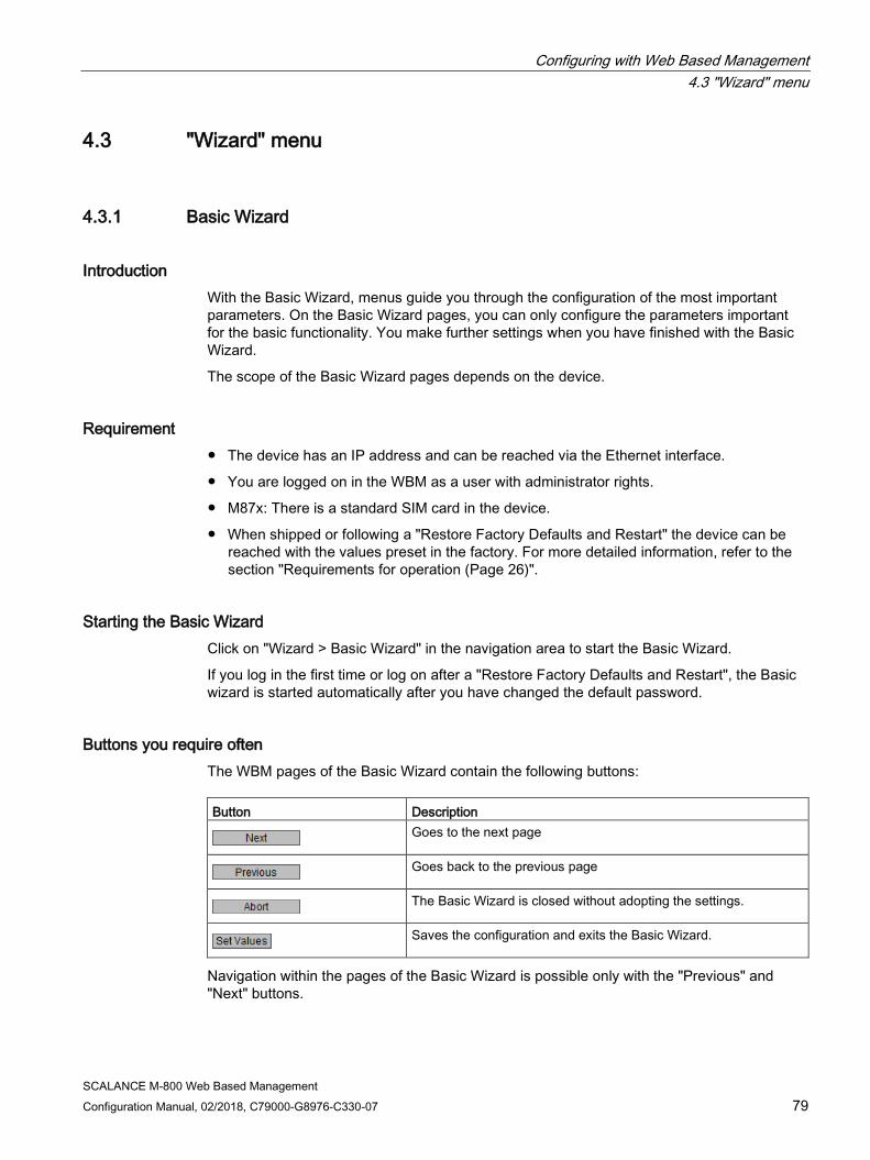
Configuring with Web Based Management 4.3 "Wizard" menu
SCALANCE M-800 Web Based Management Configuration Manual, 02/2018, C79000-G8976-C330-07 79
4.3 "Wizard" menu
4.3.1 Basic Wizard
Introduction With the Basic Wizard, menus guide you through the configuration of the most important parameters. On the Basic Wizard pages, you can only configure the parameters important for the basic functionality. You make further settings when you have finished with the Basic Wizard.
The scope of the Basic Wizard pages depends on the device.
Requirement ● The device has an IP address and can be reached via the Ethernet interface.
● You are logged on in the WBM as a user with administrator rights.
● M87x: There is a standard SIM card in the device.
● When shipped or following a "Restore Factory Defaults and Restart" the device can be reached with the values preset in the factory. For more detailed information, refer to the section "Requirements for operation (Page 26)".
Starting the Basic Wizard Click on "Wizard > Basic Wizard" in the navigation area to start the Basic Wizard.
If you log in the first time or log on after a "Restore Factory Defaults and Restart", the Basic wizard is started automatically after you have changed the default password.
Buttons you require often The WBM pages of the Basic Wizard contain the following buttons: Button Description
Goes to the next page
Goes back to the previous page
The Basic Wizard is closed without adopting the settings.
Saves the configuration and exits the Basic Wizard.
Navigation within the pages of the Basic Wizard is possible only with the "Previous" and "Next" buttons.

Configuring with Web Based Management 4.3 "Wizard" menu
SCALANCE M-800 Web Based Management 80 Configuration Manual, 02/2018, C79000-G8976-C330-07
4.3.2 IP settings
Introduction One of the basic steps in configuration of a device is setting the IP address. The IP address identifies a device in the network uniquely.
Description The Basic Wizard page contains the following boxes
● IP Address Enter an IP address that is unique within your network.
● Subnet Mask Enter the subnet mask of the device.
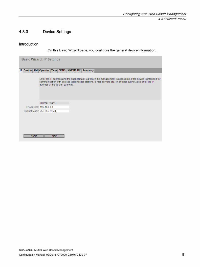
Configuring with Web Based Management 4.3 "Wizard" menu
SCALANCE M-800 Web Based Management Configuration Manual, 02/2018, C79000-G8976-C330-07 81
4.3.3 Device Settings
Introduction On this Basic Wizard page, you configure the general device information.

Configuring with Web Based Management 4.3 "Wizard" menu
SCALANCE M-800 Web Based Management 82 Configuration Manual, 02/2018, C79000-G8976-C330-07
Description The Basic Wizard page contains the following boxes
● System Name
You can enter the name of the device. If you configure this box, this configuration is adopted and displayed in the selection area. A maximum of 255 characters are possible. The system name is also displayed in the CLI input prompt. The number of characters in the CLI input prompt is limited. The system name is truncated after 16 characters.
● Device Location
You can enter the location where the device is installed. The location is displayed in the selection area. A maximum of 255 characters are possible.
Note
Permitted characters
The following printable ASCII characters (0x20 to 0x7) are permitted in the input fields: • 0123456789 • A...Z a...z • !"#$%&'()*+,-./:;<=>?@ [\]_{|}~^`
● System Contact
You can enter a contact person responsible for managing the device. A maximum of 255 characters are possible.
4.3.4 DSL
On this Basic Wizard page, you configure the DSL access and the parameters for the virtual connection via which the packets will be transferred.
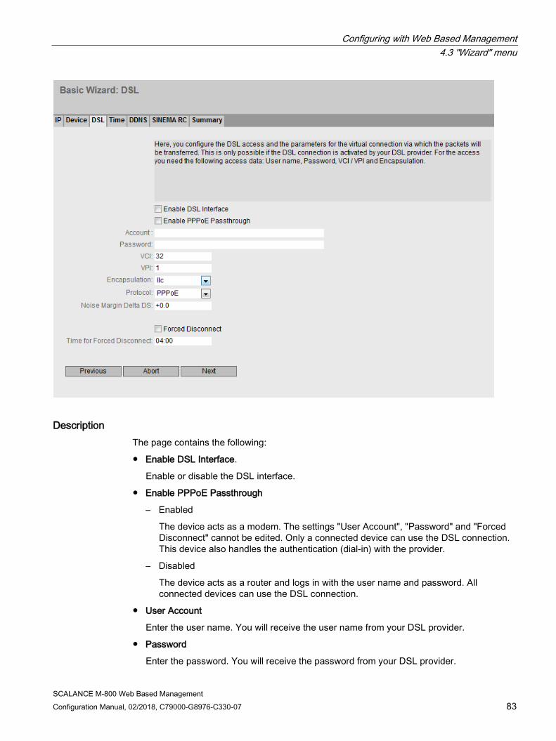
Configuring with Web Based Management 4.3 "Wizard" menu
SCALANCE M-800 Web Based Management Configuration Manual, 02/2018, C79000-G8976-C330-07 83
Description The page contains the following:
● Enable DSL Interface.
Enable or disable the DSL interface.
● Enable PPPoE Passthrough
– Enabled
The device acts as a modem. The settings "User Account", "Password" and "Forced Disconnect" cannot be edited. Only a connected device can use the DSL connection. This device also handles the authentication (dial-in) with the provider.
– Disabled
The device acts as a router and logs in with the user name and password. All connected devices can use the DSL connection.
● User Account
Enter the user name. You will receive the user name from your DSL provider.
● Password
Enter the password. You will receive the password from your DSL provider.

Configuring with Web Based Management 4.3 "Wizard" menu
SCALANCE M-800 Web Based Management 84 Configuration Manual, 02/2018, C79000-G8976-C330-07
● VCI (Virtual Channel Identifier)
Enter the ID for the virtual channel. You will receive setting from your DSL provider.
● VPI (Virtual Path Identifier)
Enter the ID for the virtual path. You will receive setting from your DSL provider.
● Encapsulation
The data packets are encapsulated in the required protocol.
The following options are available:
– vc-mux (virtual circuit multiplexing)
– LLC (Logical Link Control)
● Protocol
Specify the protocol for the Internet connection. You obtain this information from your DSL provider.
– PPPoE (Point-to-Point over Ethernet)
The PPP data is encapsulated in an Ethernet frame.
– PPPoA (Point-to-Point over ATM)
The PPP data is encapsulated in ATM AAL5 (Adaptation Layer 5). If you select PPPoA, the setting "Enable PPPoE Passthrough" is disabled.
● Noise Margin Delta DS
Specify the margin to the background noise.
● Forced Disconnect
After a certain time, the DSL provider terminates the connection. Enable this option if you want to shift the forced disconnect of your provider to a specific time of day, for example at night outside normal office hours.
● Time for Forced Disconnect
Specify the time of day to which you want to shift the forced disconnect of the DSL provider. This is only possible if the correct system time is set on the device. Input format: HH:MM
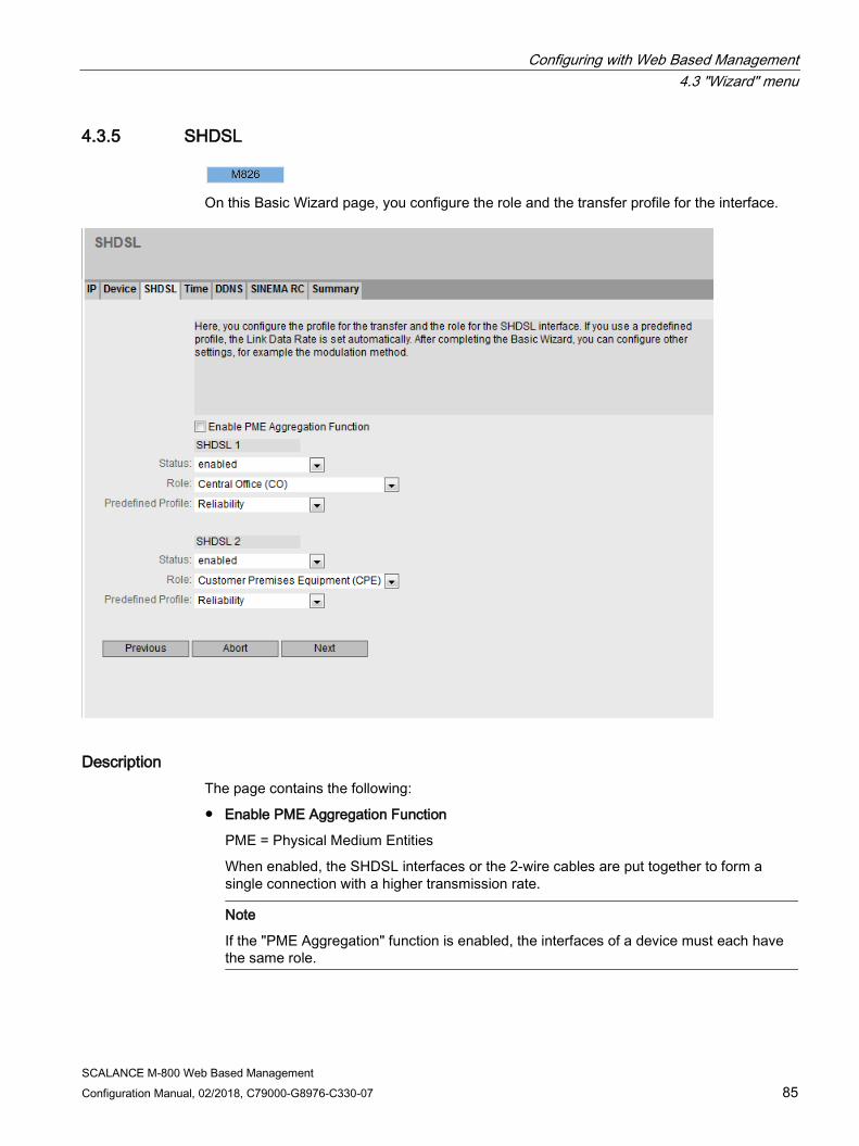
Configuring with Web Based Management 4.3 "Wizard" menu
SCALANCE M-800 Web Based Management Configuration Manual, 02/2018, C79000-G8976-C330-07 85
4.3.5 SHDSL
On this Basic Wizard page, you configure the role and the transfer profile for the interface.
Description The page contains the following:
● Enable PME Aggregation Function
PME = Physical Medium Entities
When enabled, the SHDSL interfaces or the 2-wire cables are put together to form a single connection with a higher transmission rate.
Note
If the "PME Aggregation" function is enabled, the interfaces of a device must each have the same role.

Configuring with Web Based Management 4.3 "Wizard" menu
SCALANCE M-800 Web Based Management 86 Configuration Manual, 02/2018, C79000-G8976-C330-07
The following can be configured for every SHDSI interface:
● Status
Specify whether or not the interface will be used.
● Role
Specify the role:
– Central Office (CO)
The interface is a central office.
– Customer Premises Equipment (CPE)
The interface is an end node device.
● Predefined Profile
Specify the profile for the transfer. If you use a profile, the following parameters are set automatically.
– Profiles with a transfer range
If during calibration of the cable the measured value is within the range, the SHDSL connection is established.
Link data rate min - max
Standard 192 - 5696 For medium and longer cable lengths Reliability 192 - 5696 When operating several SHDSL connections simultaneously. Extended 64 - 15296 For short and long cable length
– Profiles with a fixed preset transmission rate
If during calibration of the cable the measured value precisely matches the fixed preset transmission rate, and SHDSL connection is established.
Link Data Rate Fixed (High Rate) 5696 Fixed (Medium Rate) 3072 Fixed (Low Rate) 512

Configuring with Web Based Management 4.3 "Wizard" menu
SCALANCE M-800 Web Based Management Configuration Manual, 02/2018, C79000-G8976-C330-07 87
4.3.6 SIM
For access to the mobile wireless network and the mobile wireless services, the following access parameters are necessary. You will receive the access parameters from your mobile wireless provider.
Configuring with Web Based Management 4.3 "Wizard" menu
SCALANCE M-800 Web Based Management 88 Configuration Manual, 02/2018, C79000-G8976-C330-07
Description The Basic Wizard page contains the following:
● Enable Mobile Network Interface
Enable or disable the mobile wireless interface. The mobile wireless WLAN interfaces are disabled when the device is supplied.
● PIN Enter the PIN of the SIM card. You obtain the PIN from your mobile wireless provider. The device also works with SIM cards without a PIN, in this case leave the box empty.
Note
If you make incorrect entries, the SIM card is blocked
Make sure that you enter the PIN correctly. If you enter the PIN incorrectly more than three times, the SIM card will be blocked.
In "Information > Mobile", you can check the status of the SIM card. If "SIM Status" displays "PUK required", the SIM card is blocked.
To release it, the card needs to be taken out of the device and inserted in a mobile wireless telephone. By entering the PUK, the SIM card can be released again. If necessary, contact your mobile wireless provider.
● Radio Mode
Select the required mobile wireless network. The following options are available:
– Auto (not with the M874-2) All services. As first choice, the device attempts to establish a connection to the fastest available mobile wireless system.
– GSM only The EGPRS and GPRS services. The device ignores the UMTS and LTE network and establishes a connection to the GSM service that provides the highest bandwidth locally
– UMTS only (not with the M874-2) The UMTS and HSPA service. The device ignores the EGPRS, GPRS and LTE services and establishes a connection in the UMTS network.
– LTE only (available only with the M876-4) The LTE service. The device ignores the EGPRS and GPRS and UMTS services and establishes a connection in the LTE network.
– No data connection There is no data connection. The mode is suitable for the situation when the device only wants to send or receive SMS messages.

Configuring with Web Based Management 4.3 "Wizard" menu
SCALANCE M-800 Web Based Management Configuration Manual, 02/2018, C79000-G8976-C330-07 89
● Authentication Method
Select the required authentication method.
– CHAP Encrypted transfer of user name and password using the Challenge Handshake Authentication Protocol (CHAP).
– PAP Unencrypted transfer of user name and password using the Password Authentication Protocol (PAP).
– Auto User name and password are transferred automatically with one of the following two methods. CHAP has the higher priority. If the communications partner does not support CHAP, the user name and password are transferred using PAP.
● Allow Data Roaming
When enabled, the device automatically logs in to an available network if the specified network is unreachable.
4.3.7 Operator
The APN (Access Point Name) is the name of the access point from the mobile wireless network to the Internet or to a private company network. Depending on the type of network connected, this is a public or private APN. Information about the APN is provided by the mobile wireless provider.

Configuring with Web Based Management 4.3 "Wizard" menu
SCALANCE M-800 Web Based Management 90 Configuration Manual, 02/2018, C79000-G8976-C330-07
Description The page contains the following boxes:
● Country List
From this list, select the country in which the device will be deployed.
● Provider List
From this list select the appropriate mobile wireless provider. The list depends on the selected country.
If the mobile wireless provider is not contained in the list of providers, select "-".
● PLMNID
Each mobile wireless provider has an identification number that is unique worldwide known as the Public Land Mobile Network ID (PLMN ID). You will find the Net ID in the documentation of your mobile wireless provider or on their Internet pages.
– If you know the identification number (Net-ID) of the network provider, enter it.
– If you do not know the PLMNID enter "Manual".
● APN
Enter the name of the APN. You will find the APN in the documentation of your mobile wireless provider on your provider's Website or ask your mobile wireless provider's hotline.

Configuring with Web Based Management 4.3 "Wizard" menu
SCALANCE M-800 Web Based Management Configuration Manual, 02/2018, C79000-G8976-C330-07 91
● Username
Enter the user name. Some mobile wireless providers do not use access control with user names and/or passwords. In this case, leave the box empty.
● Password
Enter the password. Some mobile wireless providers do not use access control with user names and/or passwords. In this case, leave the box empty.
● Password Confirmation
Repeat the password.
This table contains the following columns:
● Select
Select the check box in the row to be deleted.
● PLMNID
Shows the identification number (Net ID) of the network provider.
● Operator Name
Enter the name of your mobile wireless provider.
● APN
Enter the name of the APN. You will find the APN in the documentation of your mobile wireless provider on your provider's Website or ask your mobile wireless provider's hotline.
● Username
Enter the user name for the APN. Some mobile wireless providers do not use access control with user names and/or passwords. In this case, leave the box empty.
● Password
Enter the password for the APN. Some mobile wireless providers do not use access control with user names and/or passwords. In this case, leave the box empty.
● Password Confirmation
Repeat the password.
● Enabled
The entry is used
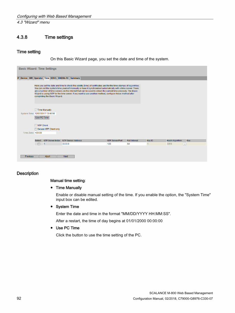
Configuring with Web Based Management 4.3 "Wizard" menu
SCALANCE M-800 Web Based Management 92 Configuration Manual, 02/2018, C79000-G8976-C330-07
4.3.8 Time settings
Time setting On this Basic Wizard page, you set the date and time of the system.
Description Manual time setting:
● Time Manually
Enable or disable manual setting of the time. If you enable the option, the "System Time" input box can be edited.
● System Time
Enter the date and time in the format "MM/DD/YYYY HH:MM:SS".
After a restart, the time of day begins at 01/01/2000 00:00:00
● Use PC Time
Click the button to use the time setting of the PC.

Configuring with Web Based Management 4.3 "Wizard" menu
SCALANCE M-800 Web Based Management Configuration Manual, 02/2018, C79000-G8976-C330-07 93
Automatic time-of-day setting with NTP
● NTP Client
Enable or disable time synchronization using NTP.
● Secure NTP Client only When enabled, the device receives the system time from a secure NTP server. The setting applies to all server entries.
To use the secure NTP client, the parameters for authentication (key ID, hash algorithm, key) must be configured.
● Time Zone
In this box, enter the time zone you are using in the format "+/- HH:MM". The time zone relates to UTC standard world time. Settings for daylight-saving and standard time are taken into account in this box by specifying the time offset.
In the table, configure the NTP server
● Select Select the row you want to delete.
● NTP Server Index
Number corresponding to a specific NTP server entry.
● NTP Server Address Enter the IP address, the FQDN (Fully Qualified Domain Name) or the host name of the NTP server.
● NTP Server Port Enter the port of the NTP server. The following ports are possible:
– 123 (standard port)
– 1025 to 36564
● Poll Interval Specify the interval between two-time queries. The greater the interval, the less accurate the time of the device.
Possible values are 64 to 2592000 seconds (30 days).
● Key ID Enter the ID of the authentication key.
● Hash Algorithm Specify the format for the authentication key.
● Key Enter the authentication key.

Configuring with Web Based Management 4.3 "Wizard" menu
SCALANCE M-800 Web Based Management 94 Configuration Manual, 02/2018, C79000-G8976-C330-07
4.3.9 DDNS On this Basic Wizard page, you configure the dynamic DNS client (DDNS client). The DDNS client synchronizes the assigned IP address with the hostname registered at the DDNS provider. This means that the device can always be reached using the same hostname.
Description The table has the following columns:
● Service
Shows which providers are supported.
● Enabled
When enabled, the device logs on to the DDNS server.
● Host
Enter the hostname that you have agreed with your DDNS provider for the device, e.g. example.no-ip-com.
● Username
Enter the user name with which the device logs on to the DDNS server.
● Password
Enter the password assigned to the user.
● Password Confirmation
Confirm the password.
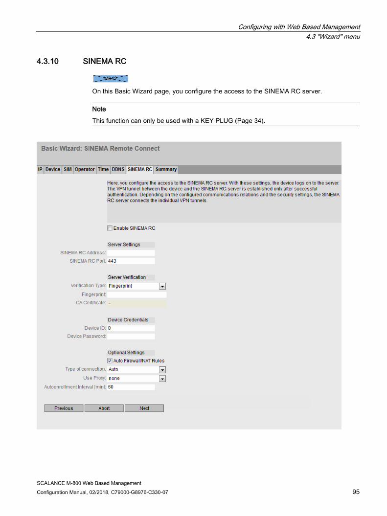
Configuring with Web Based Management 4.3 "Wizard" menu
SCALANCE M-800 Web Based Management Configuration Manual, 02/2018, C79000-G8976-C330-07 95
4.3.10 SINEMA RC
On this Basic Wizard page, you configure the access to the SINEMA RC server.
Note
This function can only be used with a KEY PLUG (Page 34).
Configuring with Web Based Management 4.3 "Wizard" menu
SCALANCE M-800 Web Based Management 96 Configuration Manual, 02/2018, C79000-G8976-C330-07
Description The page contains the following:
● Enable SINEMA RC
– Enabled:
A connection to the configured SINEMA RC Server is established. These boxes cannot be edited.
– Disabled:
The boxes can be edited. Any existing connection is terminated.
"Server settings" area
● SINEMA RC Address
Enter the IPv4 address or the DNS host name of the SINEMA RC Server.
● SINEMA RC Port
Enter the port via which the SINEMA RC Server can be reached.
"Server Verification" area
● Verification Type
– Fingerprint: The identity of the server is verified based on the fingerprint.
– CA certificate: The identity of the server is verified based on the CA certificate.
● Fingerprint
Only necessary with the setting "Fingerprint". Enter the fingerprint of the device. The fingerprint is assigned during commissioning of the SINEMA RC Server. Based on the fingerprint, the device checks whether the correct SINEMA RC Server is involved. You will find further information on this in the Operating Instructions of the SINEMA RC Server.
● CA Certificate
Only necessary with the setting "CA Certificate". Select the CA certificate of the server used to sign the server certificate. Only loaded CA certificates can be selected.
"Device Credentials" area
● Device ID
Enter the device ID. The device ID is assigned when configuring the device on the SINEMA RC Server. You will find further information on this in the Operating Instructions of the SINEMA RC Server.
● Device Password
Enter the password with which the device logs on to the SINEMA RC Server. The password is assigned when configuring the device on the SINEMA RC Server. You will find further information on this in the Operating Instructions of the SINEMA RC Server.
Configuring with Web Based Management 4.3 "Wizard" menu
SCALANCE M-800 Web Based Management Configuration Manual, 02/2018, C79000-G8976-C330-07 97
"Optional Settings" area
● Auto Firewall/NAT Rules
– Enabled
The firewall and NAT rules are created automatically for the VPN connection. The connections between the configured exported subnets and the subnets that can be reached via the SINEMA RC Server are allowed. The NAT settings are implemented as configured in the SINEMA RC Server.
– Disabled
You will need to create the firewall and NAT rules yourself.
● Type of connection
Specify the type of VPN connection. For more detailed information, refer to the section "VPN connection establishment".
– Auto
The device adopts the settings of the SINEMA RC Server. You configure the settings on the SINEMA RC Server. You will find further information on this topic in the operating instructions "SINEMA RC Server".
– Permanent
The settings of the SINEMA RC Server are ignored. The device establishes a VPN connection to the SINEMA RC Server. The VPN tunnel is established permanently
– Wake-up SMS (only with M87x)
The settings of the SINEMA RC Server are ignored. When the device receives a command SMS message (wake-up SMS message), it attempts to establish a connection to the SINEMA RC Server. On condition that in "System > SMS > SMS Command" it is specified who a command SMS of the class "System" will be accepted from.
– Digital input
The settings of the SINEMA RC Server are ignored. If the "Digital In" event occurs, the device attempts to establish a VPN connection to the SINEMA RC Server. This is on condition that the event "Digital In" is forwarded to the VPN connection. To do this in "System > Events> Configuration" activate "VPN Tunnel" for the "Digital In" event.
– Digital In & Wake-up SMS (only with M87x)
The settings of the SINEMA RC Server are ignored. If the "Digital In" event occurs or when the device receives an SMS command, it attempts to establish a VPN connection to the SINEMA RC Server.
Configuring with Web Based Management 4.3 "Wizard" menu
SCALANCE M-800 Web Based Management 98 Configuration Manual, 02/2018, C79000-G8976-C330-07
● Use Proxy
Specify whether a connection to the defined SINEMA RC Server is established via a proxy server. Only the proxy servers can be selected that you configured in "System > Proxy Server".
● Autoenrollment Interval [min]
Specify the period of time in minutes after which queries are sent to the SINEMA RC server.. With these queries, the device checks whether there is a newer firmware file on the SINEMA RC server.
If you enter the value 0, this function is disabled.
4.3.11 Summary
Introduction The settings are summarized on this page. The content of the page depends on the set parameters and the device.
Check the settings before you exit the Basic Wizard with the "Set Values" button. If settings are incorrect, go back using the "Back" button and change the settings to the required ones.

Configuring with Web Based Management 4.3 "Wizard" menu
SCALANCE M-800 Web Based Management Configuration Manual, 02/2018, C79000-G8976-C330-07 99
Set Values Click the "Set Values" button to exit the Basic Wizard. The settings are adopted.

Configuring with Web Based Management 4.4 "Information" menu
SCALANCE M-800 Web Based Management 100 Configuration Manual, 02/2018, C79000-G8976-C330-07
4.4 "Information" menu
4.4.1 Start Page
View of the Start page After logging in successfully, the start page of the WBM is displayed. You cannot configure anything on this page.
General layout of the WBM page The following areas are available on every WBM page:
● Selection area (1): Top area
● Display area (2): Top area
● Navigation area (3): Left-hand area
● Content area (4): Middle area

Configuring with Web Based Management 4.4 "Information" menu
SCALANCE M-800 Web Based Management Configuration Manual, 02/2018, C79000-G8976-C330-07 101
Configuring with Web Based Management 4.4 "Information" menu
SCALANCE M-800 Web Based Management 102 Configuration Manual, 02/2018, C79000-G8976-C330-07
Selection area (1) The following is available in the selection area:
● Logo of Siemens AG
When you click on the logo, you arrive at the Internet page of the corresponding basic device in Siemens Industry Online Support.
● Display of: "System Location / System Name"
– "System Location" contains the location of the device. With the settings when the device ships, the in-band port IP address of the device is displayed.
– "System Name" is the device name. With the settings when the device ships, the device type is displayed.
You can change the content of this display with "System > General > Devices".
● Drop-down list for language selection
● System date and system time with status display
You can change the content of this display with "System > System Time".
If the system time is not set, the status is . If the system time is configured, but the system time cannot be synchronized, a yellow warning triangle can be seen. Check whether the time server can be reached. If necessary adapt your configuration. If the system time is set and/or can be synchronized, the status is .
Display area (2) In the left-hand part of the display area, the full title of the currently selected menu item is always displayed.
● Logout
You can log out from any WBM page by clicking the "Logout" link.
● LED simulation Each device has one or more LEDs that provide information on the operating state of the device. Depending on its location, direct access to the device may not always be possible. Web Based Management therefore displays simulated LEDs. The meaning of the LED displays is described in the operating instructions.
If you click this button, you open the window for the LED simulation. You can show this window during a change of menu and move it as necessary. To close the LED simulation, click the close button in the LED simulation window.
● Help When you click this button, the help page of the currently selected menu item is opened in a new browser window.
● Printer When you click this button, a pop-up window opens with a view of the page content optimized for the printer.

Configuring with Web Based Management 4.4 "Information" menu
SCALANCE M-800 Web Based Management Configuration Manual, 02/2018, C79000-G8976-C330-07 103
● Favorites
When the product ships, the button is disabled on all pages .
If you click this button, the symbol changes and the currently open page or currently open tab is marked as favorite. Once you have enabled the button once, the navigation area is divided into two tabs. The first tab "Menu" contains all the available menus as previously. The second tab "Favorites" contains all the pages/tabs that you selected as favorites. On the "Favorites" tab the pages/tabs are arranged according to the structure in the "Menu" tab.
If you disable all the favorites you have created, the "Favorites" tab is removed again.
● Update on / Update off WBM pages with overview lists can also have the additional "Update" button.
With this button, you can enable or disable updating of the content area. If updating is turned on, the display is updated every 2 seconds. To disable the update, click "On". Instead of "On", "Off" is displayed. As default, updating is always enabled on the WBM page.
Navigation area (3) In the navigation area, you have various menus available. Click the individual menus to display the submenus. The submenus contain pages on which information is available or with which you can create configurations. These pages are always displayed in the content area.
Content area (4) In the navigation area, click a menu to display the pages of the WBM in the content area.
Below the device image, the following entries are possible:
● System Name: System name of the device
● Device Type: The type of the device
● PLUG Configuration: Shows the status of the configuration data on the PLUG, refer to the section "System > PLUG > Configuration".
● PLUG License Shows the status of the license on the PLUG, refer to the section "System > PLUG > License".
● Connection Status: Status of the connection
● Signal Level [dBm] (only with M87x) Signal strength of the connection

Configuring with Web Based Management 4.4 "Information" menu
SCALANCE M-800 Web Based Management 104 Configuration Manual, 02/2018, C79000-G8976-C330-07
● DDNS Status If a dynamic DNS service is used, the host name of the device is displayed, e.g. example.no-ip.com. The status of the update is also displayed.
– update successful Update successful
– update failed Update unsuccessful
– status unkown Status unknown
● Fault Status Displays the error status of the device.
Buttons you require often
The WBM pages contain the following standard buttons:
● Refresh the display with "Refresh" WBM pages that display current parameters have a "Refresh" button at the lower edge of the page. Click this button to request up-to-date information from the device for the current page.
Note
If you click the "Refresh" button, before you have transferred your configuration changes to the device using the "Set Values" button, your changes will be deleted and the previous configuration will be loaded from the device and displayed here.
● Save entries with "Set Values" WBM pages in which you can make configuration settings have a "Set Values" button at the lower edge. The button only becomes active if you change at least one value on the page. Click this button to save the configuration data you have entered on the device. Once you have saved, the button becomes inactive again.
Note
Changing configuration data is possible only with the "admin" role.
Note
The changes take immediate effect. But it takes some time for the changes in the configuration to be stored.
● Create entries with "Create" WBM pages in which you can make new entries have a "Create" button at the lower edge. Click this button to create a new entry.
● Delete entries with "Delete" WBM pages in which you can delete entries have a "Delete" button at the lower edge. Click this button to delete the previously selected entries from the device memory. Deleting also results in an update of the page in the WBM.
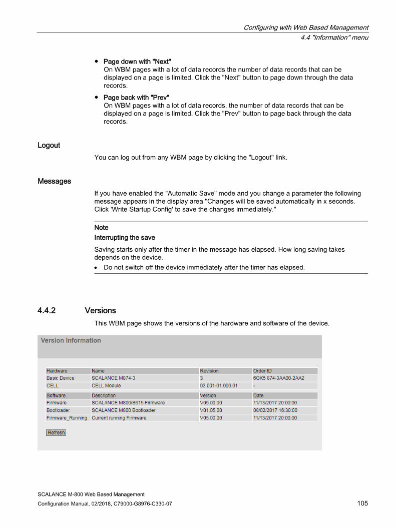
Configuring with Web Based Management 4.4 "Information" menu
SCALANCE M-800 Web Based Management Configuration Manual, 02/2018, C79000-G8976-C330-07 105
● Page down with "Next" On WBM pages with a lot of data records the number of data records that can be displayed on a page is limited. Click the "Next" button to page down through the data records.
● Page back with "Prev" On WBM pages with a lot of data records, the number of data records that can be displayed on a page is limited. Click the "Prev" button to page back through the data records.
Logout You can log out from any WBM page by clicking the "Logout" link.
Messages If you have enabled the "Automatic Save" mode and you change a parameter the following message appears in the display area "Changes will be saved automatically in x seconds. Click 'Write Startup Config' to save the changes immediately."
Note Interrupting the save
Saving starts only after the timer in the message has elapsed. How long saving takes depends on the device. • Do not switch off the device immediately after the timer has elapsed.
4.4.2 Versions This WBM page shows the versions of the hardware and software of the device.
Configuring with Web Based Management 4.4 "Information" menu
SCALANCE M-800 Web Based Management 106 Configuration Manual, 02/2018, C79000-G8976-C330-07
Description Table 1 has the following columns:
● Hardware
– Basic Device Shows the basic device
– CELL (M87x only) Shows the wireless module being used.
– xDSL (nur bei M81x)
Shows the DSL module being used
● Name Shows the name of the device.
● Revision Shows the hardware version of the device.
● Order ID Shows the article number of the device.
● Software
– Firmware Shows the current firmware version. If a new firmware file was downloaded and the device has not yet restarted, the firmware version of the downloaded firmware file is displayed here. After the next restart, the loaded firmware is activated and used.
– Bootloader Shows the version of the boot software stored on the device.
– Firmware_Running Shows the firmware version currently being used on the device.
● Description Shows the short description of the software.
● Version Shows the version number of the software version.
● Date Shows the date on which the software version was created.
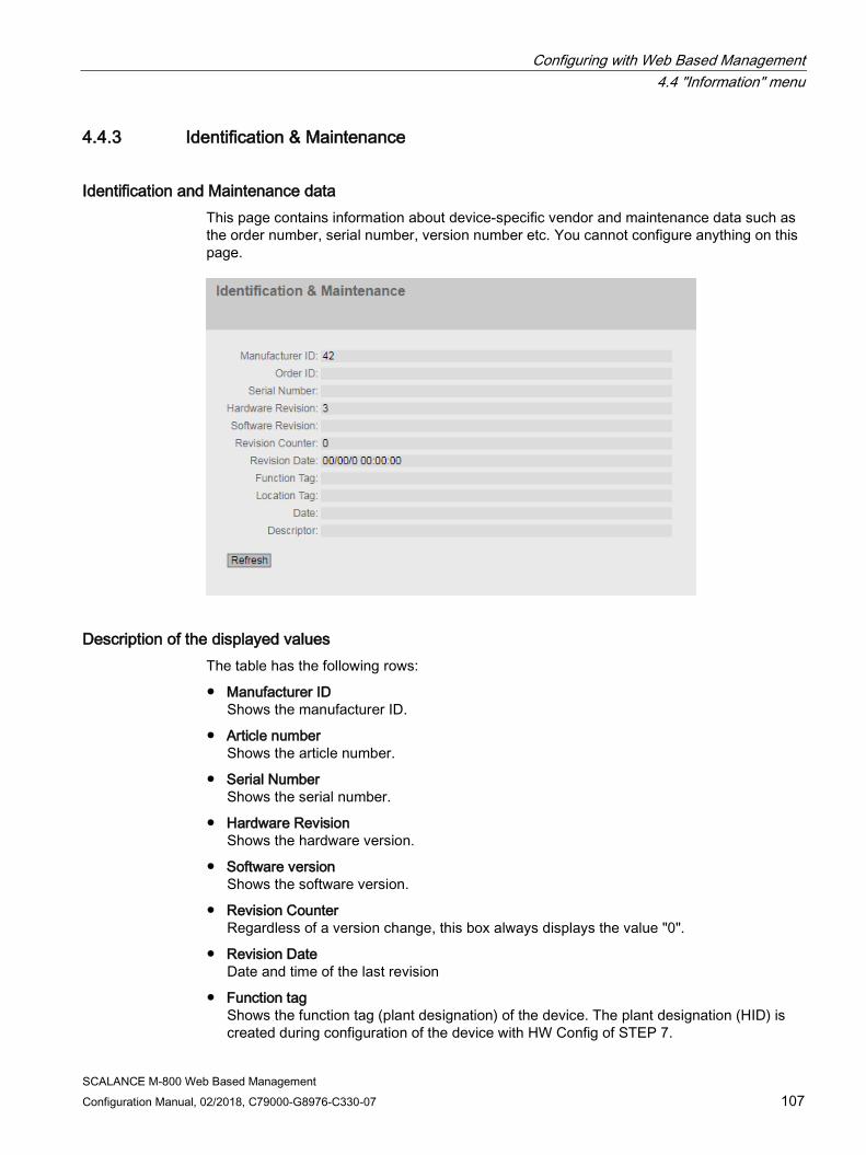
Configuring with Web Based Management 4.4 "Information" menu
SCALANCE M-800 Web Based Management Configuration Manual, 02/2018, C79000-G8976-C330-07 107
4.4.3 Identification & Maintenance
Identification and Maintenance data This page contains information about device-specific vendor and maintenance data such as the order number, serial number, version number etc. You cannot configure anything on this page.
Description of the displayed values The table has the following rows:
● Manufacturer ID Shows the manufacturer ID.
● Article number Shows the article number.
● Serial Number Shows the serial number.
● Hardware Revision Shows the hardware version.
● Software version Shows the software version.
● Revision Counter Regardless of a version change, this box always displays the value "0".
● Revision Date Date and time of the last revision
● Function tag Shows the function tag (plant designation) of the device. The plant designation (HID) is created during configuration of the device with HW Config of STEP 7.

Configuring with Web Based Management 4.4 "Information" menu
SCALANCE M-800 Web Based Management 108 Configuration Manual, 02/2018, C79000-G8976-C330-07
● Location tag Shows the location tag of the device. The location identifier (LID) is created during configuration of the device with HW Config of STEP 7.
● Date Shows the date created during configuration of the device with HW Config of STEP 7.
● Descriptor Shows the description created during configuration of the device with HW Config of STEP 7.
4.4.4 ARP Table
Assignment of MAC address and IP address With the Address Resolution Protocol (ARP), there is a unique assignment of MAC address to IP address. This assignment is kept by each network node in its own separate ARP table. The WBM page shows the ARP table of the device.
Description The table has the following columns:
● Interface Shows the interface via which the row entry was learnt.
● MAC Address Shows the MAC address of the destination or source device.
● IP Address Shows the IPv4 address of the destination device.
● Media Type Shows the type of connection.
– Dynamic The device recognized the address data automatically.
– Static
The addresses were entered as static addresses.

Configuring with Web Based Management 4.4 "Information" menu
SCALANCE M-800 Web Based Management Configuration Manual, 02/2018, C79000-G8976-C330-07 109
4.4.5 Log Tables
4.4.5.1 Event Log
Logging events The WBM page shows the system events that have occurred in the form of a table. Some of the system events can be configured in "System > Events", for example if the connection status of a port has changed.
The content of the table is retained even when the device is turned off. The event log file can be loaded using HTTP, TFTP or SFTP.

Configuring with Web Based Management 4.4 "Information" menu
SCALANCE M-800 Web Based Management 110 Configuration Manual, 02/2018, C79000-G8976-C330-07
Description ● Severity Filters
You can filter the entries in the table according to severity. To display all the entries, enable or disable all parameters.
– 2 - Critical
Critical
When this parameter is enabled, all entries of the category "Critical" are displayed.
– 4 - Warning
warning
When this parameter is enabled, all entries of the category "Warning" are displayed.
– 6 - Info
Informative
When this parameter is enabled, all entries of the category "Info" are displayed.
The table has the following columns:
● Restart Counts the number of restarts since you last reset to factory settings and shows the device restart after which the corresponding event occurred.
● System Up Time Shows the time the device has been running since the last restart when the described event occurred.
● System Time
If the system time is set, the date and time are also displayed at which the event occurred. If no system time is set, the box displays "Date/time not set".
● Severity Sorts the entry into the categories above.
● Log Message Displays a brief description of the event that has occurred.
Description of the buttons and input boxes "Clear" button
Click this button to delete the content of the event log file. All entries are deleted regardless of what you have selected in "Severity Filters".
The display is also cleared. The restart counter is only reset after you have restored the device to the factory settings and restarted the device.
Note
The number of entries in this table is restricted to 1200. The table can contain 400 entries for each severity. When this number is reached, the oldest entries of the relevant severity are discarded. The table remains permanently in memory.

Configuring with Web Based Management 4.4 "Information" menu
SCALANCE M-800 Web Based Management Configuration Manual, 02/2018, C79000-G8976-C330-07 111
"Show all" button
Click this button to display all the entries on the WBM page. Note that displaying all messages can take some time.
"Next" button
Click this button to go to the next page.
"Prev" button
Click this button to go to the previous page.
Drop-down list for page change
From the drop-down list, select the page you want to go to.
"Update" button
Refreshes the display of the values in the table.
4.4.5.2 Security Log The WBM page shows the events that occurred during communication via a secure VPN tunnel in the form of the table.

Configuring with Web Based Management 4.4 "Information" menu
SCALANCE M-800 Web Based Management 112 Configuration Manual, 02/2018, C79000-G8976-C330-07
Description ● Severity Filters
You can filter the entries in the table according to severity. To display all the entries, enable or disable all parameters.
– 2 - Critical
Critical
When this parameter is enabled, all entries of the category "Critical" are displayed.
– 4 - Warning
warning
When this parameter is enabled, all entries of the category "Warning" are displayed.
– 6 - Info
Informative
When this parameter is enabled, all entries of the category "Info" are displayed.
The table has the following columns:
● Restart Counts the number of restarts since you last reset to factory settings and shows the device restart after which the corresponding event occurred.
● System Up Time Shows the time the device has been running since the last restart when the described event occurred.
● System Time
If the system time is set, the date and time are also displayed at which the event occurred. If no system time is set, the box displays "Date/time not set".
● Severity Sorts the entry into the categories above.
● Log Message Displays a brief description of the event that has occurred.
Description of the buttons and input boxes "Clear" button
Click this button to delete the content of the event log file. All entries are deleted regardless of what you have selected in "Severity Filters".
The display is also cleared. The restart counter is only reset after you have restored the device to the factory settings and restarted the device.
Note
The number of entries in this table is restricted to 1200. The table can contain 400 entries for each severity. When this number is reached, the oldest entries of the relevant severity are discarded. The table remains permanently in memory.

Configuring with Web Based Management 4.4 "Information" menu
SCALANCE M-800 Web Based Management Configuration Manual, 02/2018, C79000-G8976-C330-07 113
"Show all" button
Click this button to display all the entries on the WBM page. Note that displaying all messages can take some time.
"Next" button
Click this button to go to the next page.
"Prev" button
Click this button to go to the previous page.
Drop-down list for page change
From the drop-down list, select the page you want to go to.
"Update" button
Refreshes the display of the values in the table.
4.4.5.3 Firewall Log The firewall log logs the events that occurred on the firewall. When you create firewall rules, you can specify the event severity with which they are logged.
Configuring with Web Based Management 4.4 "Information" menu
SCALANCE M-800 Web Based Management 114 Configuration Manual, 02/2018, C79000-G8976-C330-07
Description ● Severity Filters
You can filter the entries in the table according to severity. To display all the entries, enable or disable all parameters.
– 2 - Critical
Critical
When this parameter is enabled, all entries of the category "Critical" are displayed.
– 4 - Warning
warning
When this parameter is enabled, all entries of the category "Warning" are displayed.
– 6 - Info
Informative
When this parameter is enabled, all entries of the category "Info" are displayed.
The table has the following columns:
● Restart Counts the number of restarts since you last reset to factory settings and shows the device restart after which the corresponding event occurred.
● System Up Time Shows the time the device has been running since the last restart when the described event occurred.
● System Time
If the system time is set, the date and time are also displayed at which the event occurred. If no system time is set, the box displays "Date/time not set".
● Severity Sorts the entry into the categories above.
● Log Message Displays a brief description of the event that has occurred.
Description of the buttons and input boxes "Clear" button
Click this button to delete the content of the event log file. All entries are deleted regardless of what you have selected in "Severity Filters".
The display is also cleared. The restart counter is only reset after you have restored the device to the factory settings and restarted the device.
Note
The number of entries in this table is restricted to 1200. The table can contain 400 entries for each severity. When this number is reached, the oldest entries of the relevant severity are discarded. The table remains permanently in memory.

Configuring with Web Based Management 4.4 "Information" menu
SCALANCE M-800 Web Based Management Configuration Manual, 02/2018, C79000-G8976-C330-07 115
"Show all" button
Click this button to display all the entries on the WBM page. Note that displaying all messages can take some time.
"Next" button
Click this button to go to the next page.
"Prev" button
Click this button to go to the previous page.
Drop-down list for page change
From the drop-down list, select the page you want to go to.
"Update" button
Refreshes the display of the values in the table.
4.4.6 Faults
Error status if an error occurs, it is shown on this page. On the device, errors are indicated by red fault LED lighting up.
Internal errors of the device and errors that you configure on the following pages are indicated:
● System > Events"
● "System" > Fault Monitoring"
Errors of the "Cold/Warm Start" event can be deleted by a confirmation.
The calculation of the time of an error always begins after the last system start.
If there are no errors present, the fault LED switches off.
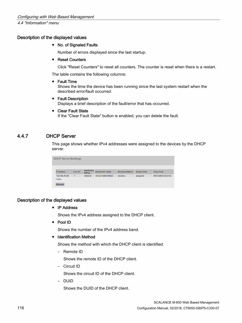
Configuring with Web Based Management 4.4 "Information" menu
SCALANCE M-800 Web Based Management 116 Configuration Manual, 02/2018, C79000-G8976-C330-07
Description of the displayed values ● No. of Signaled Faults
Number of errors displayed since the last startup.
● Reset Counters
Click "Reset Counters" to reset all counters. The counter is reset when there is a restart.
The table contains the following columns:
● Fault Time Shows the time the device has been running since the last system restart when the described error/fault occurred.
● Fault Description Displays a brief description of the fault/error that has occurred.
● Clear Fault State If the "Clear Fault State" button is enabled, you can delete the fault.
4.4.7 DHCP Server This page shows whether IPv4 addresses were assigned to the devices by the DHCP server.
Description of the displayed values ● IP Address
Shows the IPv4 address assigned to the DHCP client.
● Pool ID
Shows the number of the IPv4 address band.
● Identification Method
Shows the method with which the DHCP client is identified.
– Remote ID
Shows the remote ID of the DHCP client.
– Circuit ID
Shows the circuit ID of the DHCP client.
– DUID
Shows the DUID of the DHCP client.

Configuring with Web Based Management 4.4 "Information" menu
SCALANCE M-800 Web Based Management Configuration Manual, 02/2018, C79000-G8976-C330-07 117
● Identification Value
Shows the value that is assigned to the identification method.
● Allocation Method
Shows whether the IPv4 address was assigned statically or dynamically. You configure the static entries in "System > DHCP > Static Leases".
● Binding State Shows the status of the assignment.
– Associated The assignment is used.
– not used The assignment is not used.
– probing The assignment is being checked.
– unknown The status of the assignment is unknown.
● Expire Time Shows how long the assigned IPv4 address is still valid. When half the period of validity has elapsed. the DHCP client can extend the period of the assigned IPv4 address. When the entire time has elapsed, the DHCP client needs to request a new IPv4 address.
4.4.8 SNMP This page displays the created SNMPv3 groups. You configure the SNMPv3 groups in "System > SNMP".
Description The table has the following columns:
● Group Name
Shows the group name.
● User Name
Shows the user that is assigned to the group.
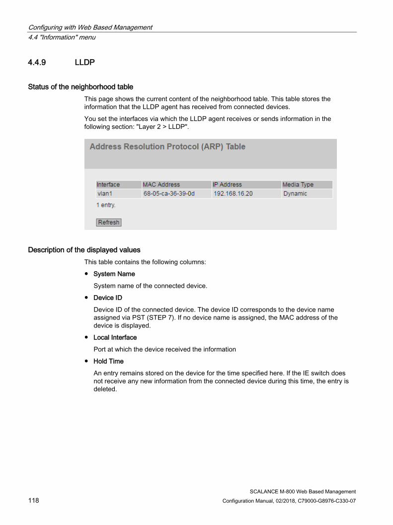
Configuring with Web Based Management 4.4 "Information" menu
SCALANCE M-800 Web Based Management 118 Configuration Manual, 02/2018, C79000-G8976-C330-07
4.4.9 LLDP
Status of the neighborhood table This page shows the current content of the neighborhood table. This table stores the information that the LLDP agent has received from connected devices.
You set the interfaces via which the LLDP agent receives or sends information in the following section: "Layer 2 > LLDP".
Description of the displayed values This table contains the following columns:
● System Name
System name of the connected device.
● Device ID
Device ID of the connected device. The device ID corresponds to the device name assigned via PST (STEP 7). If no device name is assigned, the MAC address of the device is displayed.
● Local Interface
Port at which the device received the information
● Hold Time
An entry remains stored on the device for the time specified here. If the IE switch does not receive any new information from the connected device during this time, the entry is deleted.
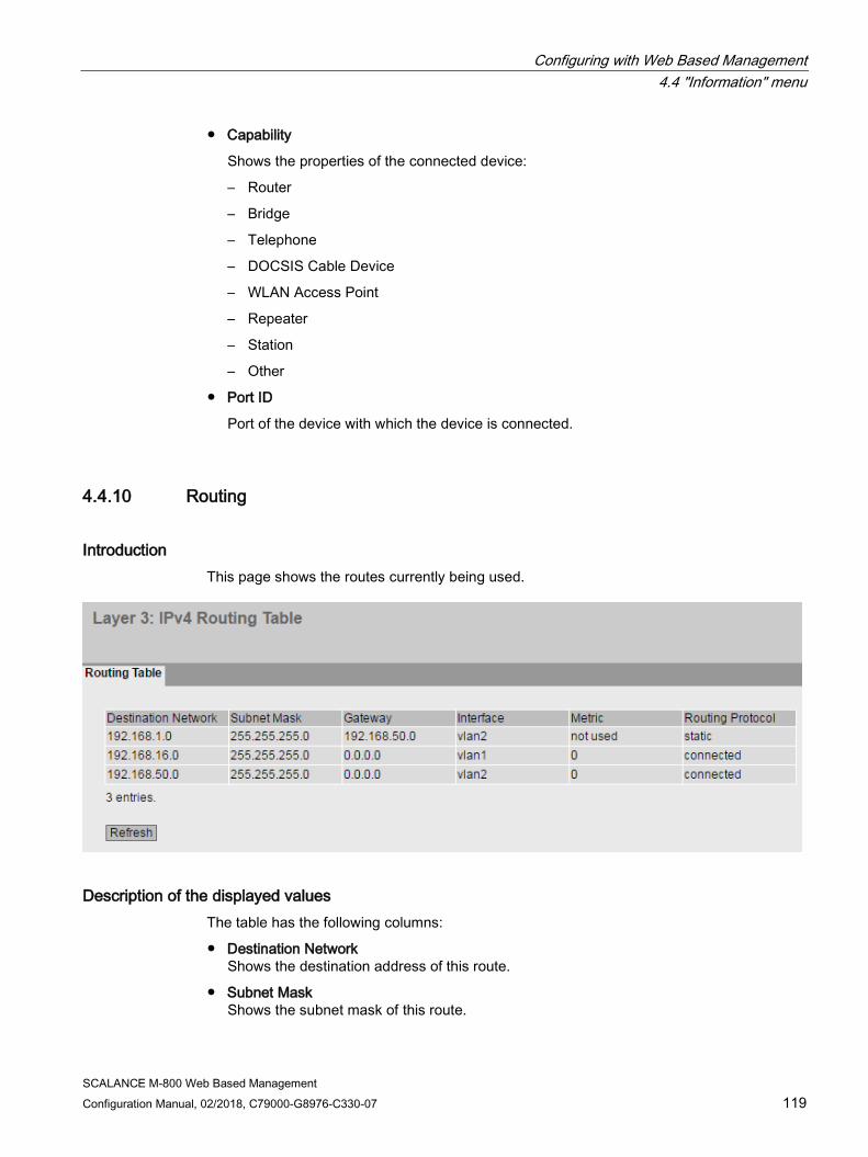
Configuring with Web Based Management 4.4 "Information" menu
SCALANCE M-800 Web Based Management Configuration Manual, 02/2018, C79000-G8976-C330-07 119
● Capability
Shows the properties of the connected device:
– Router
– Bridge
– Telephone
– DOCSIS Cable Device
– WLAN Access Point
– Repeater
– Station
– Other
● Port ID
Port of the device with which the device is connected.
4.4.10 Routing
Introduction This page shows the routes currently being used.
Description of the displayed values The table has the following columns:
● Destination Network Shows the destination address of this route.
● Subnet Mask Shows the subnet mask of this route.

Configuring with Web Based Management 4.4 "Information" menu
SCALANCE M-800 Web Based Management 120 Configuration Manual, 02/2018, C79000-G8976-C330-07
● Gateway Shows the gateway for this route.
● Interface Shows the interface for this route.
● Metric Shows the metric of the route. The higher value, the longer packets require to their destination.
● Routing Protocol Shows the routing protocol from which the entry in the routing table originates. The following entries are possible:
– Connected: Connected routes
– Static: Static routes
4.4.11 Mobile
4.4.11.1 Overview
The WBM page shows an overview of the current operating status of the device.

Configuring with Web Based Management 4.4 "Information" menu
SCALANCE M-800 Web Based Management Configuration Manual, 02/2018, C79000-G8976-C330-07 121
Description of the displayed values The page contains the following:
● IMEI Shows the IMEI number of the wireless module being used. The IMEI (= International Mobile Equipment Identity) is assigned uniquely worldwide.
● SIM Status
Shows the status of the SIM card.
– present SIM card exists
– missing SIM card missing
● PIN Status Shows the status of the PIN.
– PIN required PIN still needs to be entered.
– No PIN required PIN is not needed.
– PUK required SIM card blocked. With the PUK, the SIM card can be unblocked again.
– wrong PIN The PIN is wrong.
– PIN valid The PIN is valid.
● IMSI Shows the subscriber ID that is stored on the SIM card being used.
● Phone Number Shows the phone number of the SIM card.
If the phone number does not exist or cannot be read out, "no number" is dispayed.
● Connection Status Shows whether a wireless connection exists, and, if it does, which one:
– UMTS: IP connection via UMTS or HSPA
– GPRS: IP connection via EGPRS, GPRS or LTE
● Packet Switch Status
Shows the status of the packet switching.
● Cell ID Shows the ID of the wireless cell in which the device is logged in.
● LAC (Location Area Code)Shows the ID for the current location of the M87x within the mobile wireless network.

Configuring with Web Based Management 4.4 "Information" menu
SCALANCE M-800 Web Based Management 122 Configuration Manual, 02/2018, C79000-G8976-C330-07
● Signal Strength Shows the signal strength.
dBm < -109 No connection -109 ... -89 Bad signal strength -89 …-73 Medium signal strength > -73 Good signal strength
● Mobile Chip Temperature
Shows the temperature of the plugged-in chip.
● Provider Shows the mobile wireless provider.
● APN Shows the APN (= Access Point Name) of the wireless link that is being used.
● External IP Address Shows the WAN IP address at which the device can be reached in the mobile wireless network. The WAN IP address is assigned to the device by the service of the mobile wireless provider.
● DNS Server(s) Shows the DNS server or servers used by the device.
4.4.11.2 Signal Recorder The signal recorder shows the signal strength to the wireless cell in which the device is booked in.
Configuring with Web Based Management 4.4 "Information" menu
SCALANCE M-800 Web Based Management Configuration Manual, 02/2018, C79000-G8976-C330-07 123
Description of the displayed values The graphic contains the following elements:
● Scroll bar
With the scroll bar, you can look through the entire measurement. To do this you can use the "<<" and ">>" buttons or the arrow keys on the keyboard.
● Bar (left)
In the bar on the left-hand side the signal strength is displayed in real time according to the color scheme.
● Color scheme
Green = Good, Yellow = Medium, Orange = Weak, Red = Very weak
● x axis
The x axis shows the course of the measurement in seconds.
● Measurement data
The measurement data shows the value of the signal strength to according to the color scheme shown.
Displayed Samples
Select how many measured values will be shown in the graphic.
4.4.12 DSL
4.4.12.1 Overview
An ADSL connection consists of two endpoints known as ADSL Transceiver Units (ATU). The ADSL Transceiver Unit Remote (ATU-R) is this device and the ADSL Transceiver Unit Central (ATU-C) is the device in the central office.
The WBM page shows the current operating status of the device and contains information on the ATU-C.

Configuring with Web Based Management 4.4 "Information" menu
SCALANCE M-800 Web Based Management 124 Configuration Manual, 02/2018, C79000-G8976-C330-07
Description of the displayed values The page contains the following:
● Modem Status Shows the status of the modem. For example when initializing and when establishing the ADSL connection, the following statuses are displayed:
– showtime-sync ADSL connection is established. Data traffic possible.
– handshake ADSL connection is checked and established.
– full-init Modem is initialized.
– silent No ADSL connection
● Latency Type Shows which method is used.
– fast Fast Path: Short reply time. Less protection against interference.
– slow Protection against interference by interleaving. Interleaving means that the sequence of bits is changed and this extends the reply time.
– unkown Method unknown
● External IP Address Shows the external IP address at which the device can be reached. The IP address is assigned to the device by the service of the DSL provider.
● DNS Server(s)
Shows the DNS server or servers used by the device
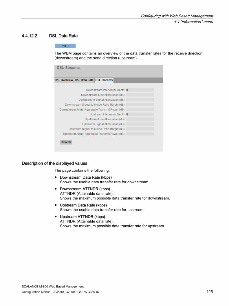
Configuring with Web Based Management 4.4 "Information" menu
SCALANCE M-800 Web Based Management Configuration Manual, 02/2018, C79000-G8976-C330-07 125
4.4.12.2 DSL Data Rate
The WBM page contains an overview of the data transfer rates for the receive direction (downstream) and the send direction (upstream).
Description of the displayed values The page contains the following:
● Downstream Data Rate (kbps) Shows the usable data transfer rate for downstream.
● Downstream ATTNDR (kbps) ATTNDR (Attainable data rate). Shows the maximum possible data transfer rate for downstream.
● Upstream Data Rate (kbps) Shows the usable data transfer rate for upstream.
● Upstream ATTNDR (kbps) ATTNDR (Attainable data rate). Shows the maximum possible data transfer rate for upstream.
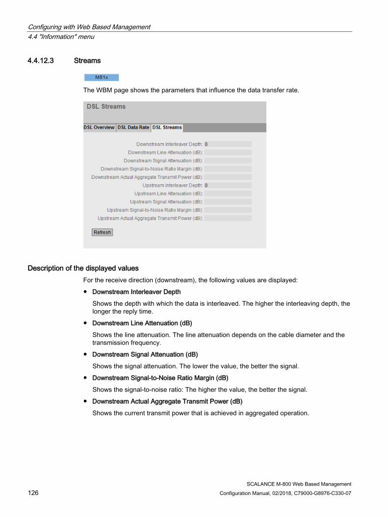
Configuring with Web Based Management 4.4 "Information" menu
SCALANCE M-800 Web Based Management 126 Configuration Manual, 02/2018, C79000-G8976-C330-07
4.4.12.3 Streams
The WBM page shows the parameters that influence the data transfer rate.
Description of the displayed values For the receive direction (downstream), the following values are displayed:
● Downstream Interleaver Depth
Shows the depth with which the data is interleaved. The higher the interleaving depth, the longer the reply time.
● Downstream Line Attenuation (dB)
Shows the line attenuation. The line attenuation depends on the cable diameter and the transmission frequency.
● Downstream Signal Attenuation (dB)
Shows the signal attenuation. The lower the value, the better the signal.
● Downstream Signal-to-Noise Ratio Margin (dB)
Shows the signal-to-noise ratio: The higher the value, the better the signal.
● Downstream Actual Aggregate Transmit Power (dB)
Shows the current transmit power that is achieved in aggregated operation.

Configuring with Web Based Management 4.4 "Information" menu
SCALANCE M-800 Web Based Management Configuration Manual, 02/2018, C79000-G8976-C330-07 127
For the send direction (upstream), the following values are displayed:
● Upstream Interleaver Depth
Shows the depth with which the data is interleaved. The higher the interleaving depth, the longer the reply time.
● Upstream Line Attenuation (dB)
Shows the line attenuation. The line attenuation depends on the cable diameter and the transmission frequency.
● Upstream Signal Attenuation (dB)
Shows the signal attenuation. The lower the value, the better the signal.
● Upstream Signal-to-Noise Ratio Margin [dB]
Shows the signal-to-noise ratio: The higher the value, the better the signal.
● Upstream Actual Aggregate Transmit Power (dB)
Shows the current transmit power that is achieved in aggregated operation.
4.4.13 SHDSL
The WBM page shows the status of the SHDSL interface.
Configuring with Web Based Management 4.4 "Information" menu
SCALANCE M-800 Web Based Management 128 Configuration Manual, 02/2018, C79000-G8976-C330-07
Description of the displayed values This table contains the following columns:
● Interface
Shows the SHDSL interfaces of the device.
● Negotiation
The following values are possible:
– down not ready (only with the CO role)
There is no electrical connection plugged into the communications partner. The driver is initialized and is ready to negotiate the connection parameters.
– down ready (only with the CPE role)
There is no electrical connection plugged into the communications partner. The driver is initialized and is ready to negotiate the connection parameters.
– initializing
The connection parameters are negotiated.
– up data mode
The connection parameters have been negotiated successfully. The data transfer is now possible.
– stop down ready
The negotiation of connection parameters was not successful or the connection was interrupted. Renegotiation of the parameters is pending.
– unknown
Driver initialization not yet completed. This status occurs following device startup.
● Data Rate [kbps]
Shows the usable data transmission rate.
● Uptime
Shows the time since the last negotiation of the connection parameters or the last connection interruption.
● SNR [dB]
Shows the signal-to-noise ratio: The higher the value, the better the signal.
● CRC Anomaly
Cyclic Redundancy Check
Shows how many SHDSL network packets were discovered with a bad checksum (CRC).
● LOSW Defect
Loss of Synchronization Word
Shows how often the synchronization was lost on the SHDSL connection.
● Negotiation Count
Shows how often the connection parameters were renegotiated.
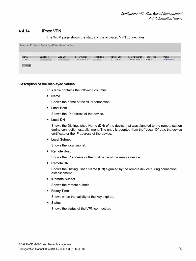
Configuring with Web Based Management 4.4 "Information" menu
SCALANCE M-800 Web Based Management Configuration Manual, 02/2018, C79000-G8976-C330-07 129
4.4.14 IPsec VPN The WBM page shows the status of the activated VPN connections.
Description of the displayed values This table contains the following columns:
● Name
Shows the name of the VPN connection.
● Local Host
Shows the IP address of the device.
● Local DN
Shows the Distinguished Name (DN) of the device that was signaled to the remote station during connection establishment. The entry is adopted from the "Local ID" box, the device certificate or the IP address of the device.
● Local Subnet
Shows the local subnet.
● Remote Host
Shows the IP address or the host name of the remote device.
● Remote DN
Shows the Distinguished Name (DN) signaled by the remote device during connection establishment.
● IRemote Subnet
Shows the remote subnet.
● Rekey Time
Shows when the validity of the key expires.
● Status
Shows the status of the VPN connection.
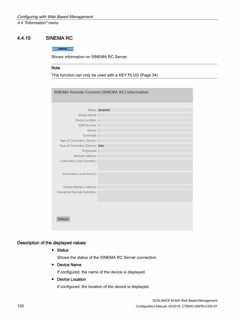
Configuring with Web Based Management 4.4 "Information" menu
SCALANCE M-800 Web Based Management 130 Configuration Manual, 02/2018, C79000-G8976-C330-07
4.4.15 SINEMA RC
Shows information on SINEMA RC Server.
Note
This function can only be used with a KEY PLUG (Page 34).
Description of the displayed values ● Status
Shows the status of the SINEMA RC Server connection.
● Device Name
If configured, the name of the device is displayed.
● Device Location
If configured, the location of the device is displayed.

Configuring with Web Based Management 4.4 "Information" menu
SCALANCE M-800 Web Based Management Configuration Manual, 02/2018, C79000-G8976-C330-07 131
● GSM Number
If configured, the phone number of the device is displayed.
● Vendor
If configured, the entry is displayed.
● Comment
If configured, the comment is displayed.
● Type of Connection (Server)
Shows which type of connection is set on the SINEMA RC Server.
● Type of Connection (Device)
Shows which type of connection is set on the device.
● Fingerprint
Shows the fingerprint of the server certificate. Is only displayed when the fingerprint is used for verification.
● Remote Address
Shows the IP address of the SINEMA RC Server.
● Connected Local Subnet(s)
Shows the IP addresses of the local subnets. Is only displayed when the option "Connected local subnets" is enabled on the SINEMA RC Server. You will find further information on this in the Operating Instructions of the SINEMA RC Server.
● Connected Local Host (s)
Shows the destination IP address of the hosts that can be reached.
● Tunnel Interface Address
Shows the IP address of the virtual tunnel interface.
● Connected Remote Subnet(s)
Shows the subnets of the SINEMA RC Server that are reachable for the device. Which subnets are reachable for the device depends on the communications relations on the SINEMA RC Server. You will find further information on this in the Operating Instructions of the SINEMA RC Server.

Configuring with Web Based Management 4.4 "Information" menu
SCALANCE M-800 Web Based Management 132 Configuration Manual, 02/2018, C79000-G8976-C330-07
4.4.16 OpenVPN client The WBM page shows the status of the activated OpenVPN connections.
Description of the displayed values This table contains the following columns:
● Name
Shows the name of the OpenVPN connection.
● Remote Server
Shows the IP address or the hostname of the OpenVPN server.
● Tunnel Interface IP
Shows the IP address of the virtual tunnel interface.
● Exported Subnets
Shows the IP address of the local subnets.
● Routed Subnets
Shows the subnets of the OpenVPN server.
● Status
Shows the status of the OpenVPN connection.
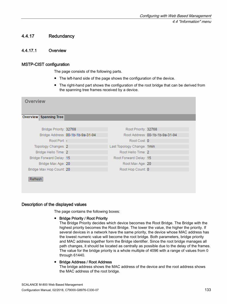
Configuring with Web Based Management 4.4 "Information" menu
SCALANCE M-800 Web Based Management Configuration Manual, 02/2018, C79000-G8976-C330-07 133
4.4.17 Redundancy
4.4.17.1 Overview
MSTP-CIST configuration The page consists of the following parts.
● The left-hand side of the page shows the configuration of the device.
● The right-hand part shows the configuration of the root bridge that can be derived from the spanning tree frames received by a device.
Description of the displayed values The page contains the following boxes:
● Bridge Priority / Root Priority The Bridge Priority decides which device becomes the Root Bridge. The Bridge with the highest priority becomes the Root Bridge. The lower the value, the higher the priority. If several devices in a network have the same priority, the device whose MAC address has the lowest numeric value will become the root bridge. Both parameters, bridge priority and MAC address together form the Bridge identifier. Since the root bridge manages all path changes, it should be located as centrally as possible due to the delay of the frames. The value for the bridge priority is a whole multiple of 4096 with a range of values from 0 through 61440.
● Bridge Address / Root Address The bridge address shows the MAC address of the device and the root address shows the MAC address of the root bridge.

Configuring with Web Based Management 4.4 "Information" menu
SCALANCE M-800 Web Based Management 134 Configuration Manual, 02/2018, C79000-G8976-C330-07
● Root Port Shows the port via which the switch communicates with the root bridge.
● Root Cost The path costs from this device to the root bridge.
● Topology Changes / Last Topology Change The entry for the device shows the number of reconfiguration actions due to the spanning tree mechanism since the last startup. For the root bridge, the time since the last reconfiguration is displayed as follows:
– Seconds: Supplement "sec" after the number
– Minutes: Supplement "min" after the number
– Hours: Supplement "hr" after the number
● Bridge hello time [s] / Root hello time [s] Each bridge sends configuration frames (BPDUs) regularly. The interval between two such frames is the Hello time. The default for this parameter is 2 seconds.
● Bridge Forward Delay / Root Forward Delay New configuration information is not used immediately by a bridge but only after the forwarding delay specified in the parameter. This ensures that operation is only started with the new topology after all the bridges have the required information. The default for this parameter is 15 seconds.
● Bridge Max Age / Root Max Age When the max age timer elapses the received BPDU is discarded to be accepted as valid by the switch. The default value is 20s.
● Bridge Max Hop Count This parameter specifies how many MSTP nodes a BPDU may pass through. If an MSTP BPDU is received and has a hop count that exceeds the value configured here, it is discarded. The default for this parameter is 20.
● Root Hop Count
The number of nodes that need to be run through on the way to the root bridge.

Configuring with Web Based Management 4.4 "Information" menu
SCALANCE M-800 Web Based Management Configuration Manual, 02/2018, C79000-G8976-C330-07 135
4.4.17.2 Spanning Tree
Introduction The page shows the current information about the spanning tree and the settings of the root bridge.
Description of the displayed values The following fields are displayed:
● Spanning Tree Mode Shows the set mode. You specify the mode in "Layer 2 > Configuration" and in "Layer 2 > Spanning Tree > General". The following values are possible:
– '-'
– RSTP
● Bridge Priority / Root Priority Which device becomes the root bridge is decided by the bridge priority. The bridge with the highest priority (in other words, with the lowest value for this parameter) becomes the root bridge. If several devices in a network have the same priority, the device whose MAC address has the lowest numeric value will become the root bridge. Both parameters, bridge priority and MAC address together form the bridge identifier. Since the root bridge manages all path changes, it should be located as centrally as possible due to the delay
Configuring with Web Based Management 4.4 "Information" menu
SCALANCE M-800 Web Based Management 136 Configuration Manual, 02/2018, C79000-G8976-C330-07
of the frames. The value for the bridge priority is a whole multiple of 4096 with a range of values from 0 to 32768.
● Bridge Address / Root Address The bridge address shows the MAC address of the device and the root address shows the MAC address of the root switch.
● Root Cost
Shows the path costs from the device to the root bridge.
● Bridge Status
Shows the status of the bridge, e.g. whether or not the device is the root bridge.
The table has the following columns:
● Port Shows the interfaces via which the device communicates.
● Role
Shows the status of the port. The following values are possible:
– Disabled The port was removed manually from the spanning tree and will no longer be taken into account by the spanning tree.
– Designated The ports leading away from the root bridge.
– Alternate The port with an alternative route to a network segment
– Backup If a switch has several ports to the same network segment, the "poorer" Port becomes the backup port.
– Root The port that provides the best route to the root bridge.
– Master This port points to a root bridge located outside the MST region.
● Status
Shows the current status of the interface. The values are only displayed. The parameter depends on the configured protocol.
– Discarding The port receives BPDU frames. Other incoming or outgoing frames are discarded.
– Listening The port receives and sends BPDU frames. The port is involved in the spanning tree algorithm. Other outgoing and incoming frames are discarded.
– Learning The port actively learns the topology; in other words, the node addresses. Other outgoing and incoming frames are discarded.
– Forwarding Following the reconfiguration time, the port is active in the network. The port receives and sends data frames.
Configuring with Web Based Management 4.4 "Information" menu
SCALANCE M-800 Web Based Management Configuration Manual, 02/2018, C79000-G8976-C330-07 137
● Oper. Version Shows the compatibility mode of Spanning Tree used by the port.
● Priority If the path calculated by the spanning tree is possible over several ports of a device, the port with the highest priority (in other words the lowest value for this parameter) is selected. A value between 0 and 240 can be entered for the priority in steps of 16. If you enter a value that cannot be divided by 16, the value is automatically adapted. The default is 128.
● Path Cost This parameter is used to calculate the path that will be selected. The path with the lowest value is selected. If several ports of a device have the same value, the port with the lowest port number is selected. If the value in the "Cost Calc" field is "0", the automatically calculated value is displayed. Otherwise, the value of the "Cost Calc" field is displayed. The calculation of the path costs is largely based on the transmission speed. The higher the achievable transmission speed is, the lower the value of the path costs.
Typical values for path costs with rapid spanning tree:
– 10,000 Mbps = 2,000
– 1000 Mbps = 20,000
– 100 Mbps = 200,000
– 10 Mbps = 2,000,000
● Edge Type Shows the type of the connection. The following values are possible:
– Edge Port There is an end device at this port.
– No Edge Port There is a spanning tree or rapid spanning tree device at this port.
● P.t.P. Type Shows the type of point-to-point link. The following values are possible:
– P.t.P. With half duplex, a point-to-point link is assumed.
– Shared Media With a full duplex connection, a point-to-point link is not assumed.
4.4.18 Security
4.4.18.1 Overview
Note
The values displayed depend on the rights of the logged-on user.
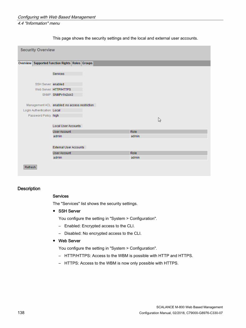
Configuring with Web Based Management 4.4 "Information" menu
SCALANCE M-800 Web Based Management 138 Configuration Manual, 02/2018, C79000-G8976-C330-07
This page shows the security settings and the local and external user accounts.
Description Services
The "Services" list shows the security settings.
● SSH Server
You configure the setting in "System > Configuration".
– Enabled: Encrypted access to the CLI.
– Disabled: No encrypted access to the CLI.
● Web Server
You configure the setting in "System > Configuration".
– HTTP/HTTPS: Access to the WBM is possible with HTTP and HTTPS.
– HTTPS: Access to the WBM is now only possible with HTTPS.
Configuring with Web Based Management 4.4 "Information" menu
SCALANCE M-800 Web Based Management Configuration Manual, 02/2018, C79000-G8976-C330-07 139
● SNMP
You can configure setting in "System > SNMP > General".
– "-" (SNMP disabled) Access to device parameters via SNMP is not possible.
– SNMPv1/v2c/v3 Access to device parameters is possible with SNMP versions 1, 2c or 3.
– SNMPv3 Access to device parameters is possible only with SNMP version 3.
● Management ACL
You configure the setting in "Security > Management ACL".
– Enabled: Restricted access only: Access is restricted using an Access Control List (ACL).
– Disabled: No access restriction: Management ACL is not enabled.
– Enabled: No access restriction: Management ACL is enabled, but access is not restricted using an Access Control List (ACL).
● Login Authentication
You configure the setting in "Security > AAA > General".
– Local
The authentication must be made locally on the device.
– RADIUS
The authentication must be handled via a RADIUS server.
– Local and RADIUS
The authentication is possible both with the users that exist on the device (user name and password) and via a RADIUS server.
The user is first searched for in the local database. If the user does not exist there, a RADIUS query is sent.
– RADIUS and fallback local
The authentication must be handled via a RADIUS server.
A local authentication is performed only when the RADIUS server cannot be reached in the network.
● Password Policy
Shows which password policy is currently being used.
Local and external user accounts
You configure local user accounts and roles in "Security > User Accounts"
When you create a local user account an external user account is generated automatically.
Local user accounts involve users each with a password for logging in on the device.

Configuring with Web Based Management 4.4 "Information" menu
SCALANCE M-800 Web Based Management 140 Configuration Manual, 02/2018, C79000-G8976-C330-07
In the table "External User Accounts" a user is linked to a role. In this example the user "Observer" is linked to the "user" role. The user is defined on a RADIUS server. The roll is defined locally on the device. When a RADIUS server authenticates a user, the corresponding group however is unknown or does not exist, the device checks whether or not there is an entry for the user in the table "External User Accounts". If an entry exists, the user is logged in with the rights of the associated role. If the corresponding group is known on the device, both tables are evaluated. The user is assigned the role with the higher rights.
Note
The table "External User Accounts" is only evaluated if you have set "SiemensVSA" in the RADIUS Authorization Mode".
With CLI you can access external user accounts.
The table "Local User Accounts" has the following columns:
● User Account
Shows the name of the local user.
● Role
Shows the role of the user. You can obtain more information on the function rights of the role in "Information > Security > Roles".
4.4.18.2 Supported Function Rights
Note
The values displayed depend on the role of the logged-on user.
The page shows the function rights available locally on the device.
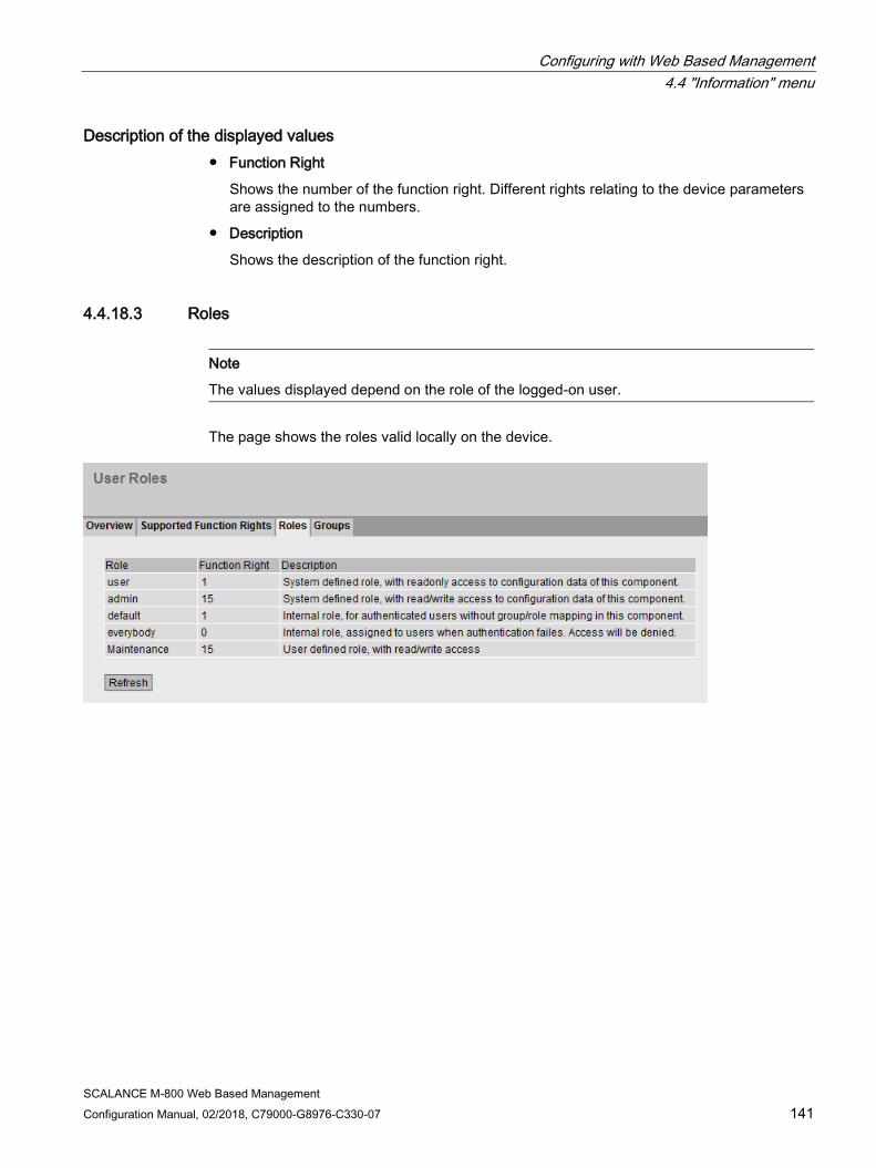
Configuring with Web Based Management 4.4 "Information" menu
SCALANCE M-800 Web Based Management Configuration Manual, 02/2018, C79000-G8976-C330-07 141
Description of the displayed values ● Function Right
Shows the number of the function right. Different rights relating to the device parameters are assigned to the numbers.
● Description
Shows the description of the function right.
4.4.18.3 Roles
Note
The values displayed depend on the role of the logged-on user.
The page shows the roles valid locally on the device.

Configuring with Web Based Management 4.4 "Information" menu
SCALANCE M-800 Web Based Management 142 Configuration Manual, 02/2018, C79000-G8976-C330-07
Description of the displayed values This table contains the following columns:
● Role
Shows the name of the role.
● Function Right
Shows the function right of the role:
– 1
Users with this role can read device parameters but cannot change them.
– 15
Users with this role can both read and change device parameters.
– 0
This is a role that the device assigns internally when a user could not be authenticated. The user is denied access to the device.
● Description
Shows a description of the role.
4.4.18.4 Groups
Note
The values displayed depend on the role of the logged-on user.
This page shows which group is linked to which role. The group is defined on a RADIUS server. The roll is defined locally on the device.

Configuring with Web Based Management 4.4 "Information" menu
SCALANCE M-800 Web Based Management Configuration Manual, 02/2018, C79000-G8976-C330-07 143
Description of the displayed values The table has the following columns:
● Group
Shows the name of the group. The name matches the group on the RADIUS server.
● Role
Shows the name of the role. Users who are authenticated with the linked group on the RADIUS server receive the rights of this role locally on the device.
● Description
Shows a a description for the link.
4.4.19 VRRPv3 Statistics
Introduction This page shows the statistics of the VRRPv3 protocol and all configured virtual routers.
Description of the displayed values The following fields are displayed:
● VRID Errors
Shows how many VRRPv3 packets containing an unsupported VRID were received.
● Version Errors
Shows how many VRRPv3 packets containing an invalid version number were received.
● Checksum Errors
Shows how many VRRPv3 packets containing an invalid checksum were received.
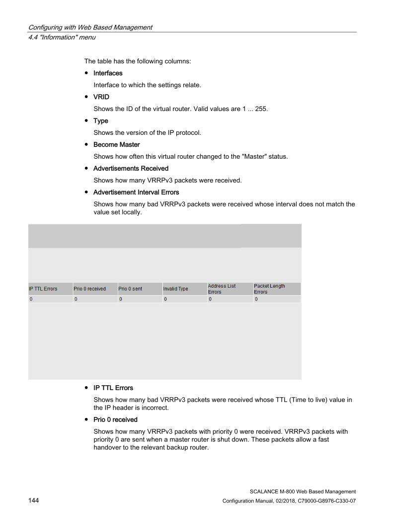
Configuring with Web Based Management 4.4 "Information" menu
SCALANCE M-800 Web Based Management 144 Configuration Manual, 02/2018, C79000-G8976-C330-07
The table has the following columns:
● Interfaces
Interface to which the settings relate.
● VRID
Shows the ID of the virtual router. Valid values are 1 ... 255.
● Type
Shows the version of the IP protocol.
● Become Master
Shows how often this virtual router changed to the "Master" status.
● Advertisements Received
Shows how many VRRPv3 packets were received.
● Advertisement Interval Errors
Shows how many bad VRRPv3 packets were received whose interval does not match the value set locally.
● IP TTL Errors
Shows how many bad VRRPv3 packets were received whose TTL (Time to live) value in the IP header is incorrect.
● Prio 0 received
Shows how many VRRPv3 packets with priority 0 were received. VRRPv3 packets with priority 0 are sent when a master router is shut down. These packets allow a fast handover to the relevant backup router.
Configuring with Web Based Management 4.5 "System" menu
SCALANCE M-800 Web Based Management Configuration Manual, 02/2018, C79000-G8976-C330-07 145
● Prio 0 sent
Shows how many VRRPv3 packets with priority 0 were sent. Packets with priority 0 are sent when a master router is shut down. These packets allow a fast handover to the relevant backup router.
● Invalid Type
Shows how many bad VRRPv3 packets were received whose value in the "Type" field of the IP header is invalid.
● Address List Errors
Shows how many bad VRRPv3 packets were received whose address list does not match the locally configured list.
● Packet Length Errors
Shows how many bad VRRPv3 packets were received whose length is not correct.
4.5 "System" menu
4.5.1 Configuration
System configuration The WBM page contains the configuration overview of the access options of the device.
Specify the services that access the device. With some services, there are further configuration pages on which more detailed settings can be made.

Configuring with Web Based Management 4.5 "System" menu
SCALANCE M-800 Web Based Management 146 Configuration Manual, 02/2018, C79000-G8976-C330-07
Description The page contains the following boxes:
● Telnet Server Enable or disable the Telnet server service for unencrypted access to the CLI.
● SSH Server Enable or disable the SSH server service for encrypted access to the CLI.
● HTTP Services
Specify how the WBM is accessed:
– HTTPS only
Access to the WBM is only possible with HTTPS.
– HTTP/HTTPS
Access to the WBM is only possible with HTTP and HTTPS.
– Redirect HTTP to HTTPS
Access via HTTP is automatically diverted to HTTPS.
● SMTP Client Enable or disable the SMTP client. You can configure other settings in "System > SMTP Client".
● Syslog Client Enable or disable the Syslog client. You can configure other settings in "System > Syslog Client".
Configuring with Web Based Management 4.5 "System" menu
SCALANCE M-800 Web Based Management Configuration Manual, 02/2018, C79000-G8976-C330-07 147
● DCP Server Specify whether or not the device can be accessed with DCP (Discovery and Configuration Protocol):
– "-" (disabled) DCP is disabled. Device parameters can neither be read nor modified.
– Read/Write With DCP, device parameters can be both read and modified.
– Read Only With DCP, device parameters can be read but cannot be modified.
● Time Select the setting from the drop-down list. The following settings are possible:
– Manual The system time is set manually. You can configure other settings in "System > System Time > Manual Setting".
– SIMATIC Time The system time is set using a SIMATIC time transmitter. You can configure other settings in "System > System Time > SIMATIC Time Client".
– SNTP Client The system time is set via an SNTP server. You can configure other settings in "System > System Time > SNTP Client".
– NTP Client The system time is set via an NTP server. You can configure other settings in "System > System Time > NTP Client".
● SNMP Select the protocol from the drop-down list. The following settings are possible:
– "-" (SNMP disabled) Access to device parameters via SNMP is not possible.
– SNMPv1/v2c/v3 Access to device parameters is possible with SNMP versions 1, 2c or 3. You can configure other settings in "System > SNMP > General".
– SNMPv3 Access to device parameters is possible only with SNMP version 3. You can configure other settings in "System > SNMP > General".
● SNMPv1/v2 Read Only Enable or disable write access to SNMP variables with SNMPv1/v2c.
● DHCP Client
Enable or disable the DHCP client. You can configure other settings in "System > DHCP".
● SNMPv1 Traps Enable or disable the sending of SNMPv1 traps (alarm frames). You can configure other settings in "System > SNMP > Traps".

Configuring with Web Based Management 4.5 "System" menu
SCALANCE M-800 Web Based Management 148 Configuration Manual, 02/2018, C79000-G8976-C330-07
● SINEMA Configuration Interface If the SINEMA configuration interface is enabled, you can download configurations to the device using STEP 7 Basic / Professional.
● Configuration Mode
Select the mode from the drop-down list. The following modes are possible:
– Automatic Save
Automatic backup mode. Approximately 1 minute after the last parameter change or before you restart the device, the configuration is automatically saved.
In addition to this, the following message appears in the display area "Changes will be saved automatically in x seconds. Click 'Write Startup Config' to save the changes immediately."
Note
Interrupting the save
Saving starts only after the timer in the message has elapsed. How long saving takes depends on the device.
During the save, the message "Saving configuration data in progress. Please do not switch off the device" is displayed. • Do not switch off the device immediately after the timer has elapsed.
– Trial
Trial mode. In Trial mode, although changes are adopted, they are not saved in the configuration file (startup configuration). To save changes in the configuration file, use the "Write startup config" button. The display area also shows the message "Trial Mode Active – Press the "Write Startup Config" button to make your settings persistent" as soon as there are unsaved modifications. This message can be seen on every WBM page until the changes made have either been saved or the device has been restarted.
Procedure 1. To use the required function, select the corresponding check box.
2. Select the options you require from the drop-down lists.
3. Click the "Set Values" button.

Configuring with Web Based Management 4.5 "System" menu
SCALANCE M-800 Web Based Management Configuration Manual, 02/2018, C79000-G8976-C330-07 149
4.5.2 General
4.5.2.1 Device This WBM page contains the general device information.
Description The WBM page contains the following boxes:
● Current System Time Shows the current system time. The system time is either set by the user or by a time-of-day frame: either SINEC H1 time-of-day frame, NTP or SNTP.
● System Up Time Shows the operating time of the device since the last restart.
● Device Type Shows the type designation of the device.
● System Name You can enter the name of the device. The entered name is displayed in the selection area. A maximum of 255 characters are possible. The system name is also displayed in the CLI input prompt. The number of characters in the CLI input prompt is limited. The system name is truncated after 16 characters.

Configuring with Web Based Management 4.5 "System" menu
SCALANCE M-800 Web Based Management 150 Configuration Manual, 02/2018, C79000-G8976-C330-07
● System Contact You can enter the name of a contact person responsible for managing the device. A maximum of 255 characters are possible.
● System Location You can enter the location where the device is installed. The entered installation location is displayed in the selection area. A maximum of 255 characters are possible.
Note
Permitted characters
The following printable ASCII characters (0x20 to 0x7e) are permitted in the input boxes "System Name", "System Contact" and "System Location": • 0123456789 • A...Z a...z • !"#$%&'()*+,-./:;<=>?@ [\]_{|}~^`
Procedure 1. Enter the contact person responsible for the device in the "System Contact" input box.
2. Enter the identifier for the location at which the device is installed in the "System Location" input box.
3. Enter the name of the device in the "System Name" input box.
4. Click the "Set Values" button.
Note: Steps 1 to 3 can also be performed with the SNMP Management Tool.
4.5.2.2 Coordinates
Information on geographic coordinates In the "Geographic Coordinates" window, you can enter information on the geographic coordinates. The parameters of the geographic coordinates (latitude, longitude and the height above the ellipsoid according to WGS84) are entered directly in the input boxes of the "Geographic Coordinates" window.

Configuring with Web Based Management 4.5 "System" menu
SCALANCE M-800 Web Based Management Configuration Manual, 02/2018, C79000-G8976-C330-07 151
Getting the coordinates
Use suitable maps for obtaining the geographic coordinates of the device.
The geographic coordinates can also be obtained using a GPS receiver. The geographic coordinates of these devices are normally displayed directly and only need to be entered in the input boxes of this page.
Description The page contains the following input boxes with a maximum length of 32 characters.
● "Latitude" input box Geographical latitude: Here, enter the value for the northerly or southerly latitude of the location of the device.
For example, the value +49° 1´31.67" means that the device is located at 49 degrees, 1 arc minute and 31.67 arc seconds northerly latitude. A southerly latitude is shown by a preceding minus character. You can also append the letters N (northerly latitude) or S (southerly latitude) to the numeric information (49° 1´31.67" N).
● "Longitude" input box Geographic longitude: Here, you enter the value of the eastern or western longitude of the location of the device. The value +8° 20´58.73" means that the device is located at 8 degrees, 20 minutes and 58.73 seconds east. A western longitude is indicated by a preceding minus sign. You can also add the letter E (easterly longitude) or W (westerly longitude) to the numeric information (8° 20´58.73" E).
● Input box: "Height" Height Here, you enter the value of the geographic height above sea level in meters. For example, 158 m means that the device is located at a height of 158 m above sea level. Heights below sea level (for example the Dead Sea) are indicated by a preceding minus sign.

Configuring with Web Based Management 4.5 "System" menu
SCALANCE M-800 Web Based Management 152 Configuration Manual, 02/2018, C79000-G8976-C330-07
Procedure 1. Enter the calculated latitude in the "Latitude" input box.
2. Enter the calculated longitude in the "Longitude" input box.
3. Enter the height above sea level in the "Height" input box.
4. Click the "Set Values" button.
4.5.3 Restart
Resetting to the defaults In this menu, there is a button with which you can restart the device and various options for resetting to the device defaults.
Note
Note the following points about restarting a device: • You can only restart the device with administrator privileges. • A device should only be restarted with the buttons of this menu and not by a power cycle
on the device. • Any modifications you have made only become active on the device after clicking the "Set
Values" button on the relevant WBM page. If the device is in "Trial Mode", configuration modifications must be saved manually before a restart. In "Autosave mode", the last changes are saved automatically before a restart.
Configuring with Web Based Management 4.5 "System" menu
SCALANCE M-800 Web Based Management Configuration Manual, 02/2018, C79000-G8976-C330-07 153
Description To restart the device, the buttons on this page provide you with the following options:
● Restart Click this button to restart the system. You must confirm the restart in a dialog box. During a restart, the device is reinitialized, the internal firmware is reloaded, and the device runs a self-test. The settings of the start configuration are retained, e.g. the IP address of the device. The learned entries in the address table are deleted. You can leave the browser window open while the device restarts. After the restart you will need to log in again.
● Restore Memory Defaults and Restart Click this button to restore the factory configuration settings with the exception of the following parameters and to restart:
– IP addresses
– Subnet mask
– IP address of the default gateway
– DHCP client ID
– DHCP
– System name
– System location
– System contact
– User names and passwords
● Restore Factory Defaults and Restart Click this button to restore the factory defaults for the configuration. The protected defaults are also reset. An automatic restart is triggered.
Note
By resetting to the factory configuration settings, the device loses its configured IP address, see section "Requirements for operation (Page 26)". • M87x, M81x: The device can once again be reached at the IP address 192.168.1.1
that was set in the factory. • M826: An IP address must be assigned to the device.

Configuring with Web Based Management 4.5 "System" menu
SCALANCE M-800 Web Based Management 154 Configuration Manual, 02/2018, C79000-G8976-C330-07
4.5.4 Load&Save
4.5.4.1 File list
Overview of the file types File type Description Config This file contains the start configuration.
Among other things, this device contains the definitions of the users, roles, groups and function rights. The passwords are stored the file "Users".
ConfigPack Detailed configuration information. for example, start configuration, users, certificates ZIP file consisting of the Config, Users and LSYS file.
Debug This file contains information for Siemens Support. It is encrypted and can be sent by e-mail to Siemens Support without any se-curity risk.
Firmware The firmware is signed and encrypted. This ensures that only firmware created by Siemens can be downloaded to the device.
HTTPSCert Default HTTPS certificates including key The preset and automatically created HTTPS certificates are self-signed. We strongly recommend that you create your own HTTPS certificates and make them available. We recommend that you use HTTPS certificates signed either by a reliable external or by an internal certification authority. The HTTPS certificate checks the identity of the device and controls the encrypted data exchange. There are files to which access is password protected. To load the file into the device, enter the password specified for the file on the WBM page "Passwords (Page 165)".
LogFile File with entries from the event log table MIB Private MSPS MIB file ModemQualityLog Text file
Among other things, these files contain information on signal strength, signal quality.
RunningCLI Text file with CLI commands This file contains an overview of the current configuration in the form of CLI commands. Passwords are masked in this file as follows: [PASSWORD] You can download the text file. The file is not intended to be uploaded again unchanged.
Script Text file with CLI commands You can upload a script file in a device. The CLI commands it contains are executed appropriately. CLI commands for saving and loading files cannot be executed with the CLI script file.
StartupInfo Startup log file This file contains the messages that were entered in the log during the last startup.
Configuring with Web Based Management 4.5 "System" menu
SCALANCE M-800 Web Based Management Configuration Manual, 02/2018, C79000-G8976-C330-07 155
File type Description Users This file contains the assignment of the user names to the corresponding
passwords. WBMFav WBM favorites
This file contains the favorites that you created in the WBM. You can download this file and upload it in other devices.
X509Cert Various nodes are certified with certificates. The following file types can be loaded into the device: • .crt, pem, zip: Maximum file name length 255 characters • .p12: Maximum file name length 248 characters There are files to which access is password protected. To load the file into the device, enter the password specified for the file on the WBM page "Passwords (Page 165)". The loaded files are listed in "Security > Certificates > Overview (Page 303)". For more information on certificates, refer to section "Certificates (Page 305)".
4.5.4.2 HTTP
Loading and saving data using HTTP The WBM allows you to store device data in an external file on your client PC or to load such data from an external file from the PC to the devices. This means, for example, that you can also load new firmware from a file located on your Admin PC. On this page, the certificates required to establish a secure VPN connection can also be loaded.
Firmware
The firmware is signed and encrypted. This ensures that only firmware created by Siemens can be downloaded to the device.
Configuration files
Note Configuration files and Trial mode/Automatic Save
In "Automatic Save" mode, the data is saved automatically before the configuration files (ConfigPack and Config) are transferred. In "Trial" mode, although the changes are adopted, they are not saved in the configuration files (ConfigPack and Config). Use the "Write Startup Config" button on the "System > Configuration" WBM page to save changes in the configuration files.
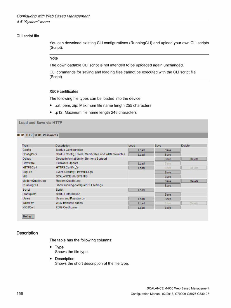
Configuring with Web Based Management 4.5 "System" menu
SCALANCE M-800 Web Based Management 156 Configuration Manual, 02/2018, C79000-G8976-C330-07
CLI script file
You can download existing CLI configurations (RunningCLI) and upload your own CLI scripts (Script).
Note
The downloadable CLI script is not intended to be uploaded again unchanged.
CLI commands for saving and loading files cannot be executed with the CLI script file (Script).
X509 certificates
The following file types can be loaded into the device:
● .crt, pem, zip: Maximum file name length 255 characters
● .p12: Maximum file name length 248 characters
Description The table has the following columns:
● Type Shows the file type.
● Description Shows the short description of the file type.

Configuring with Web Based Management 4.5 "System" menu
SCALANCE M-800 Web Based Management Configuration Manual, 02/2018, C79000-G8976-C330-07 157
● Load With this button, you can upload files to the device. The button can be enabled, if this function is supported by the file type.
● Save With this button, you can download files from the device. The button can only be enabled if this function is supported by the file type and the file exists on the device.
● Delete With this button, you can delete files from the device. The button can only be enabled if this function is supported by the file type and the file exists on the device.
Note
Following a firmware update, delete the cache of your Internet browser.
Procedure Uploading data using HTTP
1. Start the upload function by clicking one of the "Load" buttons.
Note
Files whose access is password protected
To be able to load these files on the device successfully, you need to enter the password specified for the file in "System" > "Load&Save" > "Passwords".
A dialog for uploading a file opens.
2. Select the required file and confirm the upload.
The file is uploaded.
3. If a restart is necessary, a message to this effect will be output. Click the "OK" button and run the restart. If you click the "Abort" button, there is no device restart. The changes only take effect after a restart.
Note
Cell firmware update M87x
After a cell firmware update, the device automatically restarts
Downloading data using HTTP
1. Start the download by clicking the one of the "Save" buttons.
2. Select a storage location and a name for the file.
3. Save the file.
The file is downloaded and saved.
Configuring with Web Based Management 4.5 "System" menu
SCALANCE M-800 Web Based Management 158 Configuration Manual, 02/2018, C79000-G8976-C330-07
Deleting files using HTTP
1. Start the delete function by clicking the one of the "Delete" buttons.
The file is deleted.
Reusing configuration data
If several devices are to receive the same configuration and the IP addresses are assigned using DHCP, the effort for configuration can be reduced by saving and reading in the configuration data.
Follow the steps below to reuse configuration data:
1. Save the configuration data of a configured device on your PC.
2. Load these configuration files on all other devices you want to configure in this way.
3. If individual settings are necessary for specific devices, these must be made online on the relevant device.
Note
Configuration data has a checksum. If you edit the files, you can no longer upload them to the IE switch.
4.5.4.3 TFTP
Loading and saving data using a TFTP server On this page, you can configure the TFTP server and the file names. The WBM also allows you to store device data in an external file on your client PC or to load such data from an external file from the PC to the devices. This means, for example, that you can also load new firmware from a file located on your Admin PC.
On this page, the certificates required to establish a secure VPN connection can also be loaded.
Firmware
The firmware is signed and encrypted. This ensures that only firmware created by Siemens can be downloaded to the device.
Configuration files
Note Configuration files and Trial mode/Automatic Save
In "Automatic Save" mode, the data is saved automatically before the configuration files (ConfigPack and Config) are transferred. In "Trial" mode, although the changes are adopted, they are not saved in the configuration files (ConfigPack and Config). Use the "Write Startup Config" button on the "System > Configuration" WBM page to save changes in the configuration files.

Configuring with Web Based Management 4.5 "System" menu
SCALANCE M-800 Web Based Management Configuration Manual, 02/2018, C79000-G8976-C330-07 159
CLI script file
You can download existing CLI configurations (RunningCLI) and upload your own CLI scripts (Script).
Note
The downloadable CLI script is not intended to be uploaded again unchanged.
CLI commands for saving and loading files cannot be executed with the CLI script file (Script).
X509 certificates
The following file types can be loaded into the device:
● .crt, pem, zip: Maximum file name length 255 characters
● .p12: Maximum file name length 248 characters
Description The page contains the following boxes:
● TFTP Server Address Enter the IP address or the FQDN of the TFTP server with which you exchange data.
● TFTP Server Port Enter the port of the TFTP server via which data exchange will be handled. If necessary, you can change the default value 69 to your own requirements.
Configuring with Web Based Management 4.5 "System" menu
SCALANCE M-800 Web Based Management 160 Configuration Manual, 02/2018, C79000-G8976-C330-07
The table has the following columns:
● Type Shows the file type.
● Description Shows the short description of the file type.
● Filename A file name is preset here for every file type.
Note
Changing the file name
You can change the file name preset in this column. After loading on the device, the changed file name can also be used with the Command Line Interface.
● Actions Select the action from the drop-down list. The selection depends on the selected file type, for example you can only save the log file. The following actions are possible:
– Save file With this selection, you save a file on the TFTP server.
– Load file With this selection, you load a file from the TFTP server.
Procedure Loading or saving data using TFTP
1. Enter the address of the TFTP server in "TFTP server address".
2. Enter the port of the TFTP server to be used in "TFTP Server Port".
3. If applicable, enter the name of a file in which you want to save the data or take the data from in "Filename".
Note
Files whose access is password protected
To be able to load these files on the device successfully, you need to enter the password specified for the file in "System" > "Load&Save" > "Passwords".
4. Select the action you want to execute from the "Actions" drop-down list.

Configuring with Web Based Management 4.5 "System" menu
SCALANCE M-800 Web Based Management Configuration Manual, 02/2018, C79000-G8976-C330-07 161
5. Click "Set Values" to start the selected action.
6. If a restart is necessary, a message to this effect will be output. Click the "OK" button to run the restart. If you click the "Abort" button, there is no device restart. The changes only take effect after a restart.
Note
Cell firmware update M87x
After a cell firmware update, the device automatically restarts
Reusing configuration data
If several identical devices are to receive the same configuration and the IP addresses are assigned using DHCP, the effort for reconfiguration can be reduced by saving and reading in the configuration data.
Follow the steps below to reuse configuration data:
1. Save the configuration data of a configured device on your PC.
2. Load these configuration files on all other devices you want to configure in this way.
3. If individual settings are necessary for specific devices, these must be made online on the relevant device.
Note
Configuration data has a checksum. If you change the data, you can no longer upload it to the device.
4.5.4.4 SFTP
Loading and saving data via an SFTP server SFTP (SSH File Transfer Protocol) transfers the files encrypted. On this page, you configure the access data for the SFTP server.
You can also store device data in an external file on your client PC or load such data from an external file from the PC to the devices. This means, for example, that you can also load new firmware from a file located on your Admin PC.
On this page, the certificates required to establish a secure VPN connection can also be loaded.
Firmware
The firmware is signed and encrypted. This ensures that only firmware created by Siemens can be downloaded to the device.
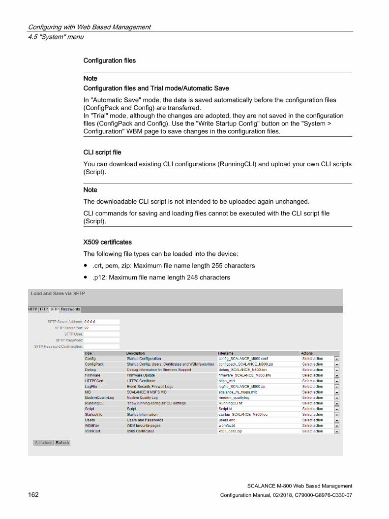
Configuring with Web Based Management 4.5 "System" menu
SCALANCE M-800 Web Based Management 162 Configuration Manual, 02/2018, C79000-G8976-C330-07
Configuration files
Note Configuration files and Trial mode/Automatic Save
In "Automatic Save" mode, the data is saved automatically before the configuration files (ConfigPack and Config) are transferred. In "Trial" mode, although the changes are adopted, they are not saved in the configuration files (ConfigPack and Config). Use the "Write Startup Config" button on the "System > Configuration" WBM page to save changes in the configuration files.
CLI script file
You can download existing CLI configurations (RunningCLI) and upload your own CLI scripts (Script).
Note
The downloadable CLI script is not intended to be uploaded again unchanged.
CLI commands for saving and loading files cannot be executed with the CLI script file (Script).
X509 certificates
The following file types can be loaded into the device:
● .crt, pem, zip: Maximum file name length 255 characters
● .p12: Maximum file name length 248 characters

Configuring with Web Based Management 4.5 "System" menu
SCALANCE M-800 Web Based Management Configuration Manual, 02/2018, C79000-G8976-C330-07 163
Description The page contains the following boxes:
● SFTP Server Address Enter the IP address or the FQDN of the SFTP server with which you exchange data.
● SFTP Server Port Enter the port of the SFTP server via which data exchange will be handled. If necessary, you can change the default value 22 to your own requirements.
● SFTP User Enter the user for access to the SFTP server. This assumes that a user with the corresponding rights has been created on the SFTP server.
● SFTP Password
Enter the password for the user
● SFTP Password Confirmation Confirm the password.
The table has the following columns:
● Type Shows the file type.
● Description Shows the short description of the file type.
● Filename A file name is preset here for every file type.
Note
Changing the file name
You can change the file name preset in this column. After loading on the device, the changed file name can also be used with the Command Line Interface.
● Actions Select the action from the drop-down list. The selection depends on the selected file type, for example you can only save the log file. The following actions are possible:
– Save file With this selection, you save a file on the SFTP server.
– Load file With this selection, you load a file from the SFTP server.

Configuring with Web Based Management 4.5 "System" menu
SCALANCE M-800 Web Based Management 164 Configuration Manual, 02/2018, C79000-G8976-C330-07
Procedure Loading or saving data using SFTP
1. Enter the address of the SFTP server in "SFTP Server Address".
2. Enter the port of the SFTP server to be used in "SFTP Server Port".
3. Enter the user data (user name and password) required for access to the SFTP server.
4. If applicable, enter the name of a file in which you want to save the data or take the data from in "Filename".
Note
Files whose access is password protected
To be able to load these files on the device successfully, you need to enter the password specified for the file in "System" > "Load&Save" > "Passwords".
5. Select the action you want to execute from the "Actions" drop-down list.
6. Click "Set Values" to start the selected action.
7. If a restart is necessary, a message to this effect will be output. Click the "OK" button to run the restart. If you click the "Abort" button, there is no device restart. The changes only take effect after a restart.
Note
Cell firmware update M87x
After a cell firmware update, the device automatically restarts
Reusing configuration data
If several identical devices are to receive the same configuration and the IP addresses are assigned using DHCP, the effort for reconfiguration can be reduced by saving and reading in the configuration data.
Follow the steps below to reuse configuration data:
1. Save the configuration data of a configured device on your PC.
2. Load these configuration files on all other devices you want to configure in this way.
3. If individual settings are necessary for specific devices, these must be made online on the relevant device.
Note
Configuration data has a checksum. If you change the data, you can no longer upload it to the IE switch.
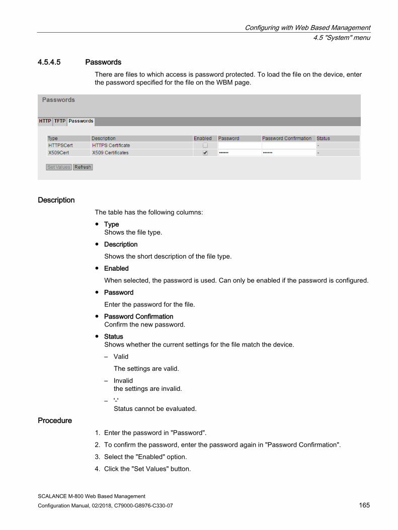
Configuring with Web Based Management 4.5 "System" menu
SCALANCE M-800 Web Based Management Configuration Manual, 02/2018, C79000-G8976-C330-07 165
4.5.4.5 Passwords There are files to which access is password protected. To load the file on the device, enter the password specified for the file on the WBM page.
Description The table has the following columns:
● Type Shows the file type.
● Description
Shows the short description of the file type.
● Enabled
When selected, the password is used. Can only be enabled if the password is configured.
● Password
Enter the password for the file.
● Password Confirmation Confirm the new password.
● Status Shows whether the current settings for the file match the device.
– Valid
The settings are valid.
– Invalid the settings are invalid.
– '-' Status cannot be evaluated.
Procedure 1. Enter the password in "Password".
2. To confirm the password, enter the password again in "Password Confirmation".
3. Select the "Enabled" option.
4. Click the "Set Values" button.

Configuring with Web Based Management 4.5 "System" menu
SCALANCE M-800 Web Based Management 166 Configuration Manual, 02/2018, C79000-G8976-C330-07
4.5.5 Events
4.5.5.1 Configuration
Selecting system events On this WBM page, you specify which system events are logged and how.
The following messages are always entered in the event log table and cannot be deselected:
● Changing the admin password
● Starting the device
● Operational status of the device, e.g. whether or not a PLUG is inserted
● Status of errors not yet dealt with
To send these messages to a Syslog server as well, enable the "Syslog" checkbox for the event "System General Logs".
Description With Table 1, you can enable or disable all check boxes of a column of Table 2 at once.
Table 1 has the following columns:
● All Events Shows that the settings are valid for all events of table 2.
● E-mail / Trap / Log- Table / Syslog / Fault / SMS / Digital Out / VPN Tunnel Enable or disable the required type of notification for all events. If "No Change" is selected, the entries of the corresponding column in table 2 remain unchanged.
● Copy To Table If you click the button, the setting is adopted for all events of table 2.

Configuring with Web Based Management 4.5 "System" menu
SCALANCE M-800 Web Based Management Configuration Manual, 02/2018, C79000-G8976-C330-07 167
Table 2 has the following columns:
● Event
The "Event" column contains the following:
– Cold/Warm Start The device was turned on or restarted by the user. In the error memory of the device a new entry is generated with the type of restart performed.
– Link Change This event occurs only when the port status is monitored and has changed, see "System > Fault Monitoring > Link Change".
– Authentication Failure This event occurs when access is attempted with an incorrect password.
– Fault State Change The fault status has changed. The fault state can relate to the activated port monitoring, the response of the signaling contact or the power supply monitoring.
– Security Logs An entry is made in the security log if the IPsec method was used for VPN.
– Firewall Logs Each time individual firewall rules are applied, this is recorded in the firewall log. To do this, the LOG function must be enabled for the various firewall functions.
– DDNS Client Logs The event occurs when the DDNS client synchronizes the assigned IP address with the hostname registered at the DDNS provider.
– System Connection Status The connection status has changed.
– System General Logs Connection establishment, change to the configuration.
– Digital In The event occurs when the status of the digital input has changed.
– VPN Tunnel The event occurs when the status of VPN (IPsec, OpenVPN, SINEMA RC) has changed.
– Secure NTP This event occurs when the device receives the system time from a secure NTP server.
– Configuration Change This event occurs when the configuration of the device has changed.
● E-mail The device sends an e-mail. This is only possible if the SMTP server is set up and the "SMTP client" function is enabled.
● Trap The device sends an SNMP trap. This is only possible if "SNMPv1 Traps" is enabled in "System > Configuration".
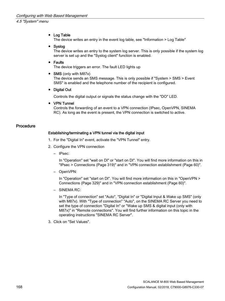
Configuring with Web Based Management 4.5 "System" menu
SCALANCE M-800 Web Based Management 168 Configuration Manual, 02/2018, C79000-G8976-C330-07
● Log Table The device writes an entry in the event log table, see "Information > Log Table"
● Syslog The device writes an entry to the system log server. This is only possible if the system log server is set up and the "Syslog client" function is enabled.
● Faults The device triggers an error. The fault LED lights up
● SMS (only with M87x) The device sends an SMS message. This is only possible if "System > SMS > Event SMS" is enabled and the telephone number of the recipient is configured.
● Digital Out
Controls the digital output or signals the status change with the "DO" LED.
● VPN Tunnel Controls the forwarding of an event to a VPN connection (IPsec, OpenVPN, SINEMA RC). As long as the event is present, the VPN connection is switched to active.
Procedure Establishing/terminating a VPN tunnel via the digital input
1. For the "Digital In" event, activate the "VPN Tunnel" entry.
2. Configure the VPN connection
– IPsec:
In "Operation" set "wait on DI" or "start on DI". You will find more information on this in "IPsec > Connections (Page 319)" and in "VPN connection establishment (Page 60)".
– OpenVPN:
In "Operation" set "start on DI". You will find more information on this in "OpenVPN > Connections (Page 329)" and in "VPN connection establishment (Page 60)".
– SINEMA RC:
In "Type of connection" set "Auto", "Digital In" or "Digital Input & Wake up SMS" (only with M87x). With "Type of connection" "Auto", on the SINEMA RC Server you need to set the type of connection "Digital In" or "Wake up SMS & digital input (only with M87x)" in "Remote connections". You will find further information on this topic in the operating instructions "SINEMA RC Server".
3. Click on "Set Values".
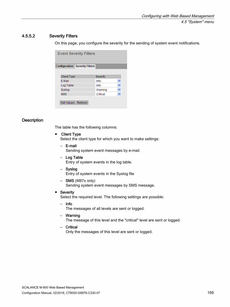
Configuring with Web Based Management 4.5 "System" menu
SCALANCE M-800 Web Based Management Configuration Manual, 02/2018, C79000-G8976-C330-07 169
4.5.5.2 Severity Filters On this page, you configure the severity for the sending of system event notifications.
Description The table has the following columns:
● Client Type Select the client type for which you want to make settings:
– E-mail Sending system event messages by e-mail.
– Log Table Entry of system events in the log table.
– Syslog Entry of system events in the Syslog file
– SMS (M87x only) Sending system event messages by SMS message.
● Severity Select the required level. The following settings are possible:
– Info The messages of all levels are sent or logged.
– Warning The message of this level and the "critical" level are sent or logged.
– Critical Only the messages of this level are sent or logged.
Configuring with Web Based Management 4.5 "System" menu
SCALANCE M-800 Web Based Management 170 Configuration Manual, 02/2018, C79000-G8976-C330-07
4.5.6 SMTP client
Network monitoring with e-mails The device provides the option of automatically sending an e-mail if an alarm event occurs (for example to the network administrator). The e-mail contains the identification of the sending device, a description of the cause of the alarm in plain language, and a time stamp. This allows centralized network monitoring to be set up for networks with few nodes based on an e-mail system. When an e-mail error message is received, the WBM can be started by the Internet browser using the identification of the sender to read out further diagnostics information.
On this page, you can configure up to three SMTP servers and the corresponding e-mail addresses.
Description The page contains the following boxes:
● SMTP Client Enable or disable the SMTP client.
● Sender Email Address Enter the name of the sender to be included in the e-mail, for example the device name.
This setting applies to all configured SMTP servers.
● Send Test Mail
Send a test e-mail to check your configuration.

Configuring with Web Based Management 4.5 "System" menu
SCALANCE M-800 Web Based Management Configuration Manual, 02/2018, C79000-G8976-C330-07 171
● SMTP Port
Enter the port via which your SMTP server can be reached.
Factory settings: 25
This setting applies to all configured SMTP servers.
● SMTP Server Address Enter the IP address, the FQDN (Fully Qualified Domain Name) or the host name of the SMTP server.
This table contains the following columns:
● Select Select the check box in a row to be deleted.
● SMTP Server Address Shows the IP address, the FQDN (Fully Qualified Domain Name) or the host name of the SMTP server.
● Receiver Email Address Enter the e-mail address to which the device sends an e-mail if a fault occurs.
Procedure 1. Enable the "SMTP Client" option.
2. Enter the IP address, the FQDN or the host name of the SMTP server in the "SMTP Server Address" input box.
3. Click the "Create" button. A new entry is generated in the table.
4. In the Receiver Email Address input box. enter the e-mail address to which the device sends an e-mail if a fault occurs.
5. Click the "Set Values" button.
Note
Depending on the properties and configuration of the SMTP server, it may be necessary to adapt the "Sender E-Mail Address” input box for the e-mails. Check with the administrator of the SMTP server.
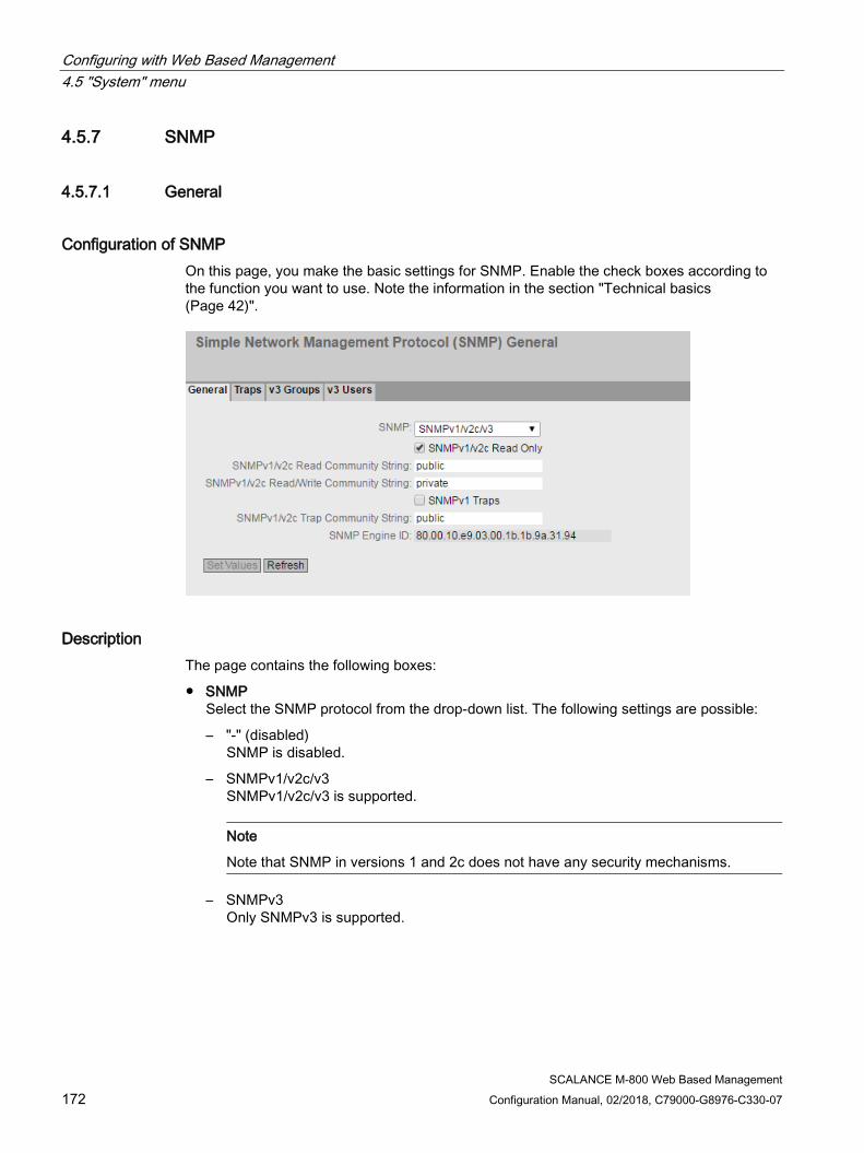
Configuring with Web Based Management 4.5 "System" menu
SCALANCE M-800 Web Based Management 172 Configuration Manual, 02/2018, C79000-G8976-C330-07
4.5.7 SNMP
4.5.7.1 General
Configuration of SNMP On this page, you make the basic settings for SNMP. Enable the check boxes according to the function you want to use. Note the information in the section "Technical basics (Page 42)".
Description The page contains the following boxes:
● SNMP Select the SNMP protocol from the drop-down list. The following settings are possible:
– "-" (disabled) SNMP is disabled.
– SNMPv1/v2c/v3 SNMPv1/v2c/v3 is supported.
Note
Note that SNMP in versions 1 and 2c does not have any security mechanisms.
– SNMPv3 Only SNMPv3 is supported.

Configuring with Web Based Management 4.5 "System" menu
SCALANCE M-800 Web Based Management Configuration Manual, 02/2018, C79000-G8976-C330-07 173
● SNMPv1/v2c Read Only If you enable this option, SNMPv1/v2c can only read the SNMP variables.
Note
Community String
For security reasons, do not use the standard values "public" or "private". Change the community strings following the initial installation.
The recommended minimum length for community strings is 6 characters.
● SNMPv1/v2c Read Community String Enter the community string for read access of the SNMP protocol.
● SNMPv1/v2c Read/Write Community String Enter the community string for read and write access of the SNMP protocol.
● SNMPv1 Traps Enable or disable the sending of SNMPv1 traps (alarm frames). On the "Trap" tab, specify the IP addresses of the devices to which SNMPv1 traps will be sent.
● SNMPv1/v2c Trap Community String Enter the community string for sending SNMPv1/v2c messages.
● SNMPv3 User Migration
– Enabled
If the function is enabled, an SNMP engine ID is generated that can be migrated. You can transfer configured SNMPv3 users to a different device.
If you enable this function and load the configuration of the device on another device, configured SNMPv3 users are retained.
– Disabled
If the function is disabled, a device-specific SNMP engine ID is generated. To generate the ID, the agent MAC address of the device is used. You cannot transfer this SNMP user configuration to other devices.
If you load the configuration of the device on another device, all configured SNMPv3 users are deleted.
● SNMP Engine ID
Shows the SNMP engine ID.
Procedure 1. Select the required option from the "SNMP" drop-down list:
– "-" (disabled)
– SNMPv1/v2c/v3
– SNMPv3
2. Enable the "SNMPv1/v2c Read Only" check box if you only want read access to SNMP variables with SNMPv1/v2c.
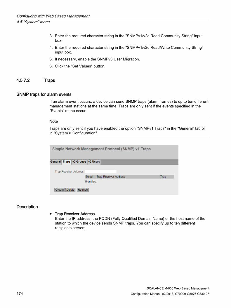
Configuring with Web Based Management 4.5 "System" menu
SCALANCE M-800 Web Based Management 174 Configuration Manual, 02/2018, C79000-G8976-C330-07
3. Enter the required character string in the "SNMPv1/v2c Read Community String" input box.
4. Enter the required character string in the "SNMPv1/v2c Read/Write Community String" input box.
5. If necessary, enable the SNMPv3 User Migration.
6. Click the "Set Values" button.
4.5.7.2 Traps
SNMP traps for alarm events If an alarm event occurs, a device can send SNMP traps (alarm frames) to up to ten different management stations at the same time. Traps are only sent if the events specified in the "Events" menu occur.
Note
Traps are only sent if you have enabled the option "SNMPv1 Traps" in the "General" tab or in "System > Configuration".
Description ● Trap Receiver Address
Enter the IP address, the FQDN (Fully Qualified Domain Name) or the host name of the station to which the device sends SNMP traps. You can specify up to ten different recipients servers.

Configuring with Web Based Management 4.5 "System" menu
SCALANCE M-800 Web Based Management Configuration Manual, 02/2018, C79000-G8976-C330-07 175
The table has the following columns:
● Select Select the row you want to delete.
● Trap Receiver Address If necessary, change the IP address, the FQDN (Fully Qualified Domain Name) or the host name of the stations.
● Trap Enable or disable the sending of traps. Stations that are entered but not selected do not receive SNMP traps.
Procedure Creating a trap entry
1. In "Trap Receiver Address", enter the IP address, the FQDN or the host name of the station to which the device will send traps.
2. Click the "Create" button to create a new trap entry.
3. Select the check box in the required row "Trap".
4. Click the "Set Values" button.
Deleting a trap entry
1. Enable "Select" in the row to be deleted.
2. Click the "Delete" button. The entry is deleted.
4.5.7.3 v3 Groups
Security settings and assigning permissions SNMP version 3 allows permissions to be assigned, authentication, and encryption at protocol level. The security level and read/write permissions are assigned according to groups. The settings automatically apply to every member of a group.
Configuring with Web Based Management 4.5 "System" menu
SCALANCE M-800 Web Based Management 176 Configuration Manual, 02/2018, C79000-G8976-C330-07
Description The page contains the following boxes:
● Group Name Enter the name of the group. The maximum length is 32 characters.
● Security Level Select the security level (authentication, encryption) valid for the selected group. The available options are as follows:
– no Auth/no Priv No authentication enabled / no encryption enabled.
– Auth/no Priv Authentication enabled / no encryption enabled.
– Auth/Priv Authentication enabled / encryption enabled.
The table has the following columns:
● Select Select the row you want to delete.
● Group Name Shows the defined group names.
● Security Level Shows the configured security level.
● Read Enable or disable read access for the required group.
● Write Enable or disable write access for the required group.
Note
For write access to work, you also need to enable read access.
● Persistence Shows whether or not the group is assigned to an SNMPv3 user. If the group is not assigned to an SNMPv3 user, no automatic saving is triggered and the configured group is deleted after restarting the device.
– Yes
The group is assigned to an SNMPv3 user.
– No
The group is not assigned to an SNMPv3 user.

Configuring with Web Based Management 4.5 "System" menu
SCALANCE M-800 Web Based Management Configuration Manual, 02/2018, C79000-G8976-C330-07 177
Procedure Creating a new group
1. Enter the required group name in "Group Name".
2. Select the required security level from the "Security Level" drop-down list.
3. Click the "Create" button to create a new entry.
4. Specify the required read rights for the group in "Read".
5. Specify the required write rights for the group in "Write".
6. Click the "Set Values" button.
Modifying a group
1. Specify the required read rights for the group in "Read".
2. Specify the required write rights for the group in "Write".
3. Click the "Set Values" button.
Note
Once a group name and the security level have been specified, they can no longer be modified after the group is created. If you want to change the group name or the security level, you will need to delete the group and recreate it and reconfigure it with the new name.
Deleting a group
1. Enable "Select" in the row to be deleted. Repeat this for all groups you want to delete.
2. Click the "Delete" button. The entries are deleted.

Configuring with Web Based Management 4.5 "System" menu
SCALANCE M-800 Web Based Management 178 Configuration Manual, 02/2018, C79000-G8976-C330-07
4.5.7.4 v3 users
User-specific security settings On the WBM page, you can create new SNMPv3 users and modify or delete existing users. The user-based security model works with the concept of the user name; in other words, a user ID is added to every frame. This user name and the applicable security settings are checked by both the sender and recipient.
Description The page contains the following boxes:
● User Name Enter a freely selectable user name. After you have entered the data, you can no longer modify the name.
The table has the following columns:
● Select Select the row you want to delete.
● User Name Shows the created users.

Configuring with Web Based Management 4.5 "System" menu
SCALANCE M-800 Web Based Management Configuration Manual, 02/2018, C79000-G8976-C330-07 179
● Group Name Select the group which will be assigned to the user.
● Authentication Protocol
Specify the authentication protocol for which a password will be stored.
The following settings are available:
– None
– MD5
– SHA
● Encryption Protocol
Specify whether or not a password should be stored for encryption with the DES algorithm. Can only be enabled when an authentication protocol has been selected.
● Authentication Password Enter the authentication password in the first input box. This password must have at least 1 character, the maximum length is 32 characters.
Note
Length of the password
As an important measure to maximize security, we recommend that the password has a minimum length of 6 characters and that it contains special characters, uppercase/lowercase letters, numbers.
● Authentication Password Confirmation Confirm the password by repeating the entry.
● Privacy Password Enter your encryption password. This password must have at least 1 character, the maximum length is 32 characters.
Note
Length of the password
As an important measure to maximize security, we recommend that the password has a minimum length of 6 characters and that it contains special characters, uppercase/lowercase letters, numbers.
Configuring with Web Based Management 4.5 "System" menu
SCALANCE M-800 Web Based Management 180 Configuration Manual, 02/2018, C79000-G8976-C330-07
● Privacy Password Confirmation Confirm the encryption password by repeating the entry.
● Persistence Shows whether or not the user is assigned to an SNMPv3 group. If the user is not assigned to an SNMPv3 group, no automatic saving is triggered and the configured user is deleted after restarting the device.
– Yes
The user is assigned to an SNMPv3 group.
– No
The user is not assigned to an SNMPv3 group.
Procedure Create a new user
1. Enter the name of the new user in the "User Name" input box.
2. Click the "Create" button. A new entry is generated in the table.
3. In "Group Name", select the group to which the new user will belong.
If the group has not yet been created, change to the "v3 Groups" page and make the settings for this group.
4. If an authentication is necessary for the selected group, select the authentication algorithm in "Authentication Protocol". In the relevant input boxes, enter the authentication password and its confirmation.
5. If encryption was specified for the group, select the algorithm in "Privacy Protocol". In the relevant input boxes, enter the encryption password and the confirmation.
6. Click the "Set Values" button.
Delete user
1. Enable "Select" in the row to be deleted. Repeat this for all users you want to delete.
2. Click the "Delete" button. The entry is deleted.
4.5.8 System Time There are different methods that can be used to set the system time of the device. Only one method can be active at any one time.
If one method is activated, the previously activated method is automatically deactivated.

Configuring with Web Based Management 4.5 "System" menu
SCALANCE M-800 Web Based Management Configuration Manual, 02/2018, C79000-G8976-C330-07 181
4.5.8.1 Manual Setting
Manual setting of the system time On this page, you set the date and time of the system yourself. For this setting to be used, enable "Time Manually".
Description The page contains the following boxes:
● Time Manually Enable or disable the manual time setting. If you enable the option, the "System Time" input box can be edited.
● System Time Enter the date and time in the format "MM/DD/YYYY HH:MM:SS".
After a restart, the time of day begins at 01/01/2000 00:00:00
● Use PC Time Click the button to use the time setting of the PC.

Configuring with Web Based Management 4.5 "System" menu
SCALANCE M-800 Web Based Management 182 Configuration Manual, 02/2018, C79000-G8976-C330-07
● Last Synchronization Time Shows when the last time-of-day synchronization took place. If no time-of-day synchronization was possible, the box displays "Date/time not set".
● Last Synchronization Mechanism Shows how the last time synchronization was performed.
– Not set The time was not set.
– Manual Manual time setting
– SNTP Automatic time-of-day synchronization with SNTP
– NTP Automatic time-of-day synchronization with NTP
– SIMATIC Automatic time-of-day synchronization using the SIMATIC time frame
Procedure 1. Enable the "Time Manually" option.
2. Click in the "System Time" input box.
3. In the "System Time" input box, enter the date and time in the format "MM/DD/YYYY HH:MM:SS".
4. Click the "Set Values" button. The date and time are adopted and "Manual" is entered in "Last Synchronization Mechanism" box.
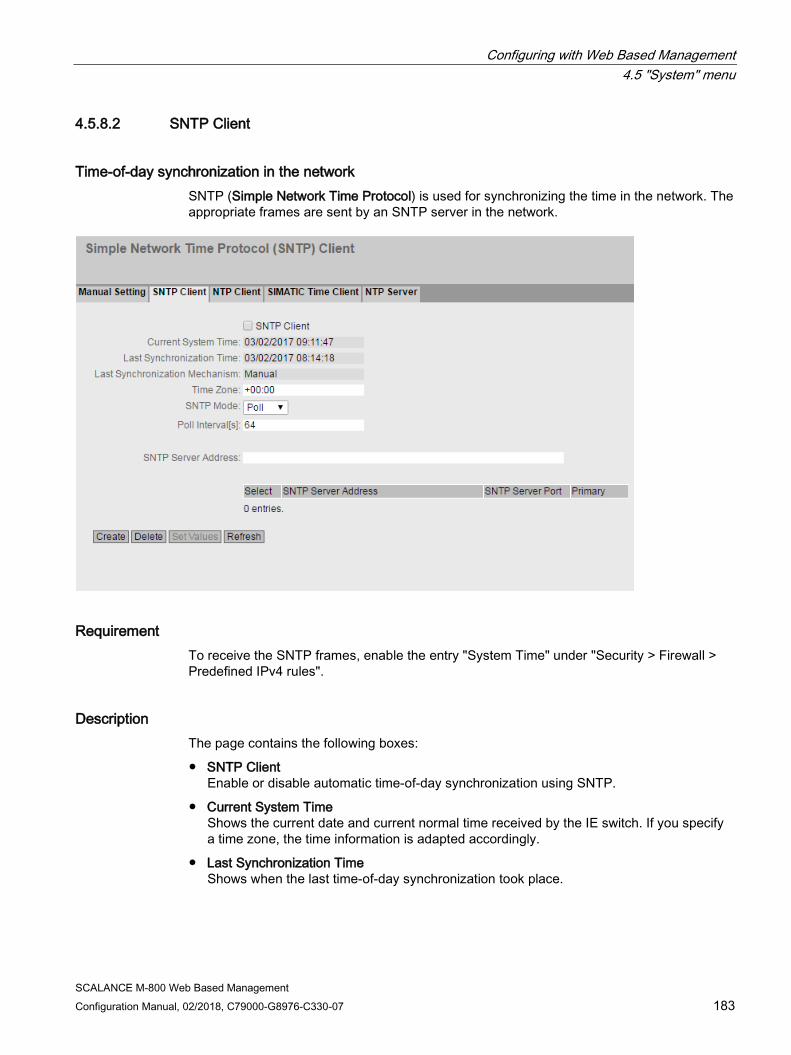
Configuring with Web Based Management 4.5 "System" menu
SCALANCE M-800 Web Based Management Configuration Manual, 02/2018, C79000-G8976-C330-07 183
4.5.8.2 SNTP Client
Time-of-day synchronization in the network SNTP (Simple Network Time Protocol) is used for synchronizing the time in the network. The appropriate frames are sent by an SNTP server in the network.
Requirement To receive the SNTP frames, enable the entry "System Time" under "Security > Firewall > Predefined IPv4 rules".
Description The page contains the following boxes:
● SNTP Client Enable or disable automatic time-of-day synchronization using SNTP.
● Current System Time Shows the current date and current normal time received by the IE switch. If you specify a time zone, the time information is adapted accordingly.
● Last Synchronization Time Shows when the last time-of-day synchronization took place.
Configuring with Web Based Management 4.5 "System" menu
SCALANCE M-800 Web Based Management 184 Configuration Manual, 02/2018, C79000-G8976-C330-07
● Last Synchronization Mechanism Shows how the last time synchronization was performed. The following methods are possible:
– Not set The time was not set.
– Manual Manual time setting
– SNTP Automatic time-of-day synchronization with SNTP
– NTP Automatic time-of-day synchronization with NTP
– SIMATIC Automatic time-of-day synchronization using the SIMATIC time frame
● Time Zone In this box, enter the time zone you are using in the format "+/- HH:MM". The time zone relates to UTC standard world time.
The time in the "Current System Time" box is adapted accordingly.
● SNTP Mode Select the synchronization mode from the drop-down list. The following types of synchronization are possible:
– Poll If you select this protocol type, the input boxes "SNTP Server Address", "SNTP Server Port" and "Poll Interval[s]" are displayed to allow further configuration. With this type of synchronization, the device is active and sends a time query to the SNTP server.
In this mode, IPv4 and IPv6 addresses are supported.
– Listen With this type of synchronization, the device is passive and receives SNTP frames that deliver the time of day. For this mode create the following firewall rules from "VLANx" to "Device" manually. In this mode, only IPv4 addresses are supported.
● SNTP Server Address Enter the IP address, the FQDN (Fully Qualified Domain Name) or the host name of the SNTP server.
● SNTP Server Port Enter the port of the SNTP server. The following ports are possible:
– 123 (standard port)
– 1025 to 36564
● Poll Interval[s] Here, enter the interval between two-time queries. In this box, you enter the query interval in seconds. Possible values are 16 to 16284 seconds.
Configuring with Web Based Management 4.5 "System" menu
SCALANCE M-800 Web Based Management Configuration Manual, 02/2018, C79000-G8976-C330-07 185
Procedure 1. Click the "SNTP Client" check box to enable the automatic time setting.
2. In "Time Zone", enter the local time difference to world time (UTC).
The input format is "+/-HH:MM" because the NTP server always sends UTC time, for example +02:00 for CEST, the Central European Summer Time. This time is recalculated and displayed as the local time based on the specified time zone.
3. Select one of the following options from the "SNTP Mode" drop-down list:
– Poll For this mode, you need to configure the following: - time zone difference (step 2) - query interval (step 4) -time server (step 5) - Port (step 7) - complete the configuration with step 8.
– Listen For this mode, you need to configure the following: - time difference to the time sent by the server (step 2) - time server (step 5) - port (step 7) - complete the configuration with step 8.
4. In "SNTP Server Address", enter the address of the SNTP server whose frames will be used to synchronize the time of day.
5. In "SNTP Server Port", enter the port via which the SNTP server is available. The port can only be modified if the IP address of the SNTP server is entered.
6. In "Poll Interval[s]", enter the time in seconds after which a new time query is sent to the time server.
7. Click the "Set Values" button.

Configuring with Web Based Management 4.5 "System" menu
SCALANCE M-800 Web Based Management 186 Configuration Manual, 02/2018, C79000-G8976-C330-07
4.5.8.3 NTP client
Automatic time-of-day setting with NTP If you require time-of-day synchronization using NTP, you can make the relevant settings here.
Requirement To receive the NTP frames, enable the entry "System Time" under "Security > Firewall > Predefined IPv4 rules".
Description The page contains the following boxes:
● NTP client When enabled, the device receives the system time from an NTP server.
● Secure NTP Client only When enabled, the device receives the system time from a secure NTP server. The setting applies to all server entries.
To use the secure NTP client, the parameters for authentication (key ID, hash algorithm, key) must be configured.
● Current System Time Shows the current date and current normal time received by the device. If you specify a time zone, the time information is adapted accordingly.
● Last Synchronization Time Shows when the last time-of-day synchronization took place.
Configuring with Web Based Management 4.5 "System" menu
SCALANCE M-800 Web Based Management Configuration Manual, 02/2018, C79000-G8976-C330-07 187
● Last Synchronization Mechanism Shows how the last time synchronization was performed. The following methods are possible:
– Not set The time was not set.
– Manual Manual time setting
– SNTP Automatic time-of-day synchronization with SNTP
– NTP Automatic time-of-day synchronization with NTP
– SIMATIC Automatic time-of-day synchronization using the SIMATIC time frame
– PTP Automatic time-of-day synchronization with PTP
● Time Zone In this box, enter the time zone you are using in the format "+/- HH:MM". The time zone relates to UTC standard world time.
The time in the "Current System Time" box is adapted accordingly.
● NTP Server Index Select the index of the NTP server. The server with the lowest index is queried first.
In the table, configure the NTP server
● Select Select the row you want to delete.
● NTP Server Index Number corresponding to a specific NTP server entry.
● NTP Server Address Enter the IP address, the FQDN (Fully Qualified Domain Name) or the host name of the NTP server.
● NTP Server Port Enter the port of the NTP server. The following ports are possible:
– 123 (standard port)
– 1025 to 36564
● Poll Interval Specify the interval between two-time queries. The greater the interval, the less accurate the time of the device.
Possible values are 64 to 2592000 seconds (30 days).
● Key ID Enter the ID of the authentication key.
● Hash Algorithm Specify the format for the authentication key.
Configuring with Web Based Management 4.5 "System" menu
SCALANCE M-800 Web Based Management 188 Configuration Manual, 02/2018, C79000-G8976-C330-07
● Key Enter the authentication key.
● Key confirmation
Repeat the authentication key.
Procedure Time-of-day synchronization with NTP server
1. Click in the "NTP Client" check box to enable the automatic time setting using NTP.
2. In "Time Zone", enter the local time difference to world time (UTC).
The input format is "+/-HH:MM" because the NTP server always sends UTC time, for example +02:00 for CEST, the Central European Summer Time. This time is recalculated and displayed as the local time based on the specified time zone.
3. Select the "NTP Server Index".
4. Click the "Create" button.
A new row is inserted in the table for the NTP server.
5. In "NTP Server Address", enter the address of the NTP server whose frames will be used to synchronize the time of day.
6. In "NTP Server Port", enter the port via which the NTP server is available. The port can only be modified if the address of the NTP server is entered.
7. In the "Poll Interval" column, enter the interval in seconds after which a new time-of-day query is sent to the time server.
8. Click the "Set Values" button.
Time-of-day synchronization via a secure NTP server
To synchronize the time of day via a secure NTP server, the following additional steps are necessary:
1. Click in the "Secure NTP Client only" check box to enable the automatic time setting using Secure NTP.
2. Configure the authentication.
– In "Key ID" enter the ID of the authentication key.
– In "Hash Algorithm" select the required format.
– In "Key"enter the authentication key.
With these entries, the NTP client authenticates itself with the secure NTP server. These entries must be present on the secure NTP server.
3. Click the "Set Values" button.
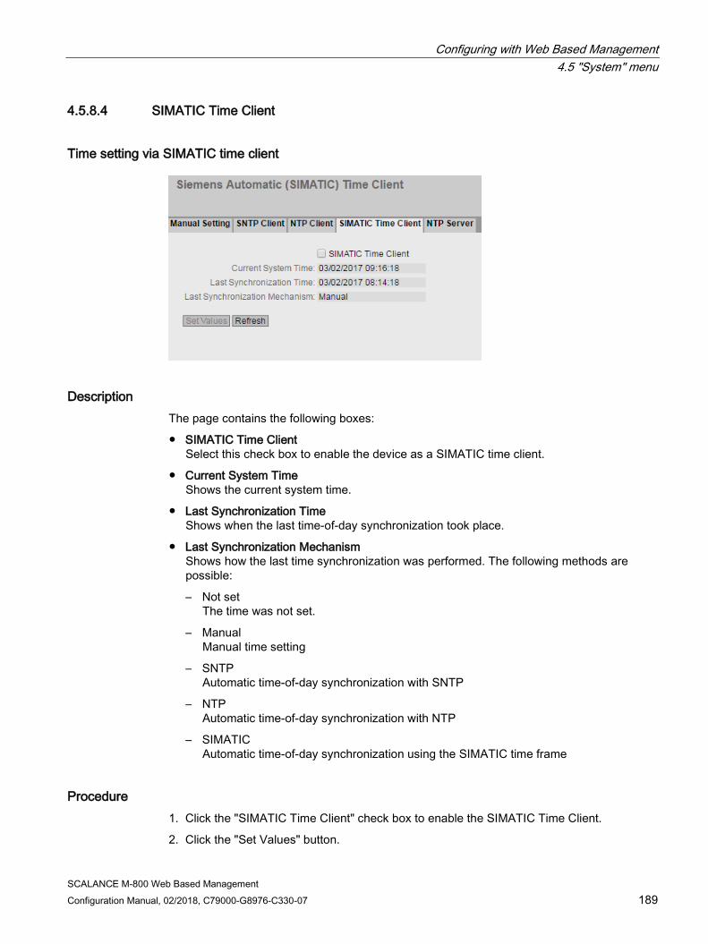
Configuring with Web Based Management 4.5 "System" menu
SCALANCE M-800 Web Based Management Configuration Manual, 02/2018, C79000-G8976-C330-07 189
4.5.8.4 SIMATIC Time Client
Time setting via SIMATIC time client
Description The page contains the following boxes:
● SIMATIC Time Client Select this check box to enable the device as a SIMATIC time client.
● Current System Time Shows the current system time.
● Last Synchronization Time Shows when the last time-of-day synchronization took place.
● Last Synchronization Mechanism Shows how the last time synchronization was performed. The following methods are possible:
– Not set The time was not set.
– Manual Manual time setting
– SNTP Automatic time-of-day synchronization with SNTP
– NTP Automatic time-of-day synchronization with NTP
– SIMATIC Automatic time-of-day synchronization using the SIMATIC time frame
Procedure 1. Click the "SIMATIC Time Client" check box to enable the SIMATIC Time Client.
2. Click the "Set Values" button.

Configuring with Web Based Management 4.5 "System" menu
SCALANCE M-800 Web Based Management 190 Configuration Manual, 02/2018, C79000-G8976-C330-07
4.5.8.5 NTP Server On this WBM page, you configure the device as an NTP server. The other devices can call up the time made available by the device via this NTP server. This means that the supplied devices are not dependent on a connection to an external time server.
Note Time synchronization
Also configure the device as NTP client so that it synchronizes the connected devices to a correct time. As NTP client, the device gets the precise time from an external time server and as NTP server distributes it to its NTP clients.
Requirement ● To receive the NTP frames, enable the entry "System Time" under "Security > Firewall >
Predefined IPv4 rules".
Description The page contains the following box:
● NTP Server
Enable or disable the NTP server service.

Configuring with Web Based Management 4.5 "System" menu
SCALANCE M-800 Web Based Management Configuration Manual, 02/2018, C79000-G8976-C330-07 191
Table 1 has the following columns:
● At all interfaces
Shows that the settings are valid for all interfaces of table 2.
● Listen
Select the setting for all interfaces. If "No Change" is selected, the entries of the corresponding column in table 2 remain unchanged.
● Copy to Table
If you click the button, the setting is adopted for all interfaces of table 2.
Table 2 has the following columns:
● Interface
Via this interface the time is transferred using NTP.
● Listen
When enabled, the other devices can call up the time via this interface.
4.5.9 Automatic Logout
Setting the automatic logout On this page, set the times after which there is an automatic logout from WBM or the CLI following user in activity.
If you have been logged out automatically, you will need to log in again.
Note No automatic logout from the CLI
If the connection is not terminated after the set time, check the "Keep alive" setting on the Telnet client.
If the interval is shorter than the configured time, the connection is kept alive although no user data is transferred. You have set, for example, 300 seconds for the automatic logoff and the "Keep alive" function is set to 120 seconds. In this case, a packet is sent every 120 seconds that keeps the connection up. • Turn off the "Keep alive" (interval time=0)
or • Set the interval high enough so that the underlying connection is terminated when there is
inactivity.

Configuring with Web Based Management 4.5 "System" menu
SCALANCE M-800 Web Based Management 192 Configuration Manual, 02/2018, C79000-G8976-C330-07
Procedure 1. Enter a value of 60-3600 seconds in the "Web Base Management (s)" input box. If you
enter the value 0, the automatic logout is disabled.
2. Enter a value of 60-600 seconds in the "CLI (TELNET, SSH) (s)" input box. If you enter the value 0, the automatic logout is disabled.
3. Click the "Set Values" button.
4.5.10 Button
Functionality The SET button is used for:
● Restart
● Loading new firmware,
● Resetting to factory settings.
You will find a detailed description of the functions in the device operating instructions.
On this page, the functionality of the button can be restricted.
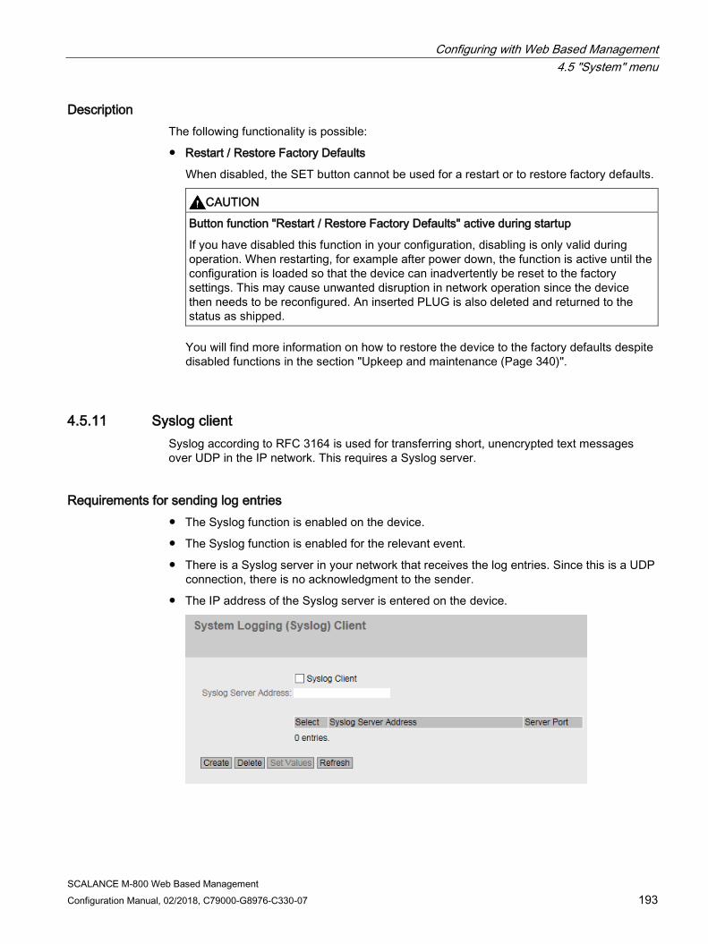
Configuring with Web Based Management 4.5 "System" menu
SCALANCE M-800 Web Based Management Configuration Manual, 02/2018, C79000-G8976-C330-07 193
Description The following functionality is possible:
● Restart / Restore Factory Defaults
When disabled, the SET button cannot be used for a restart or to restore factory defaults.
CAUTION
Button function "Restart / Restore Factory Defaults" active during startup
If you have disabled this function in your configuration, disabling is only valid during operation. When restarting, for example after power down, the function is active until the configuration is loaded so that the device can inadvertently be reset to the factory settings. This may cause unwanted disruption in network operation since the device then needs to be reconfigured. An inserted PLUG is also deleted and returned to the status as shipped.
You will find more information on how to restore the device to the factory defaults despite disabled functions in the section "Upkeep and maintenance (Page 340)".
4.5.11 Syslog client Syslog according to RFC 3164 is used for transferring short, unencrypted text messages over UDP in the IP network. This requires a Syslog server.
Requirements for sending log entries ● The Syslog function is enabled on the device.
● The Syslog function is enabled for the relevant event.
● There is a Syslog server in your network that receives the log entries. Since this is a UDP connection, there is no acknowledgment to the sender.
● The IP address of the Syslog server is entered on the device.

Configuring with Web Based Management 4.5 "System" menu
SCALANCE M-800 Web Based Management 194 Configuration Manual, 02/2018, C79000-G8976-C330-07
Description The page contains the following boxes:
● Syslog Client
Enable or disable the Syslog function.
● Syslog Server Address
Enter the IP address of the Syslog server.
This table contains the following columns
● Select
Select the row you want to delete.
● Syslog Server Address
Shows the IP address of the Syslog server.
● Server Port
Enter the port of the Syslog server being used.
Procedure Enabling function
1. Select the "Syslog Client" check box.
2. Click the "Set Values" button.
Creating a new entry
1. In the "Syslog Server Address" input box, enter the IP address of the Syslog server on which the log entries will be saved.
2. Click the "Create" button. A new row is inserted in the table.
3. In the "Server Port" input box, enter the number of the UDP port of the server.
4. Click the "Set Values" button.
Note
The default setting of the server port is 514.
Changing the entry
1. Delete the entry.
2. Create a new entry.
Deleting an entry
1. Select the check box in the row to be deleted.
2. Click the "Delete" button. All selected entries are deleted and the display is refreshed.
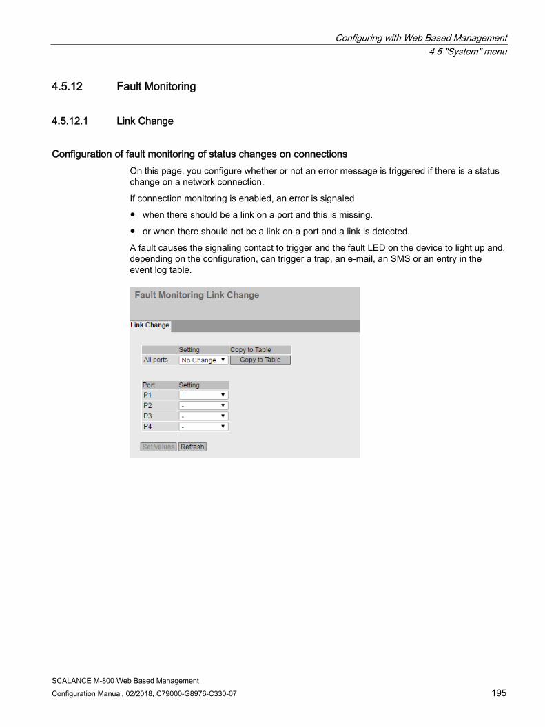
Configuring with Web Based Management 4.5 "System" menu
SCALANCE M-800 Web Based Management Configuration Manual, 02/2018, C79000-G8976-C330-07 195
4.5.12 Fault Monitoring
4.5.12.1 Link Change
Configuration of fault monitoring of status changes on connections On this page, you configure whether or not an error message is triggered if there is a status change on a network connection.
If connection monitoring is enabled, an error is signaled
● when there should be a link on a port and this is missing.
● or when there should not be a link on a port and a link is detected.
A fault causes the signaling contact to trigger and the fault LED on the device to light up and, depending on the configuration, can trigger a trap, an e-mail, an SMS or an entry in the event log table.
Configuring with Web Based Management 4.5 "System" menu
SCALANCE M-800 Web Based Management 196 Configuration Manual, 02/2018, C79000-G8976-C330-07
Description Table 1 has the following columns:
● 1st column Shows that the settings are valid for all ports.
● Setting Select the setting from the drop-down list. You have the following setting options:
– "-" (disabled)
– Up
– Down
– No Change: The setting in table 2 remains unchanged.
● Copy to Table
If you click the button, the setting is adopted for all ports of table 2.
Table 2 has the following columns:
● Port Shows the available ports and link aggregations. The port is made up of the module number and the port number, for example port 0.1 is module 0, port 1.
● Setting
Select the setting from the drop-down list. You have the following options:
– Up Error handling is triggered when the port changes to the active status.
(From "Link down" to "Link up")
– Down Error handling is triggered when the port changes to the inactive status.
(From "Link up" to "Link down")
– "-" (disabled) The error handling is not triggered.
Procedure Configure error monitoring for a port
1. From the relevant drop-down list, select the options of the slots / ports whose connection status you want to monitor.
2. Click the "Set Values" button.
Configure error monitoring for all ports
1. Select the required setting from the drop-down list of the "Setting" column.
2. Click the "Copy to table" button. The setting is adopted for all ports of table 2.
3. Click the "Set Values" button.

Configuring with Web Based Management 4.5 "System" menu
SCALANCE M-800 Web Based Management Configuration Manual, 02/2018, C79000-G8976-C330-07 197
4.5.12.2 Mobile wireless
On this page, you configure whether or not an error message is triggered if there is a status change of the SIM card.
Description The table has the following columns:
● SIM card
Shows the available SIM cards.
● Setting Select the setting from the drop-down list. You have the following options:
– "-" (disabled) The error handling is not triggered.
– SIM missing Troubleshooting is triggered if no SIM card is plugged in. An error causes the fault LED to light up on the device.
4.5.13 PLUG
4.5.13.1 Configuration

Configuring with Web Based Management 4.5 "System" menu
SCALANCE M-800 Web Based Management 198 Configuration Manual, 02/2018, C79000-G8976-C330-07
NOTICE
Do not remove or insert a C-PLUG / KEY-PLUG during operation!
A PLUG may only be removed or inserted when the device is turned off. The device checks whether or not a PLUG is present at one second intervals. If it is detected that the PLUG was removed, there is a restart. If a valid KEY-PLUG was inserted in the device, the device changes to a defined error state following the restart. With SCALANCE M, the available wireless interfaces are deactivated in this case.
If the device was configured at some time with a PLUG, the device can no longer be used without this PLUG. To be able to use the device again, reset the device to the factory settings.
Information about the configuration of the KEY-PLUG This page provides detailed information about the configuration stored on the C-PLUG. It is also possible to reset the PLUG to "factory defaults" or to load it with new contents.
Note Incompatibility with previous versions with PLUG inserted
During the installation of a previous version, the configuration data can be lost. In this case, the device starts up with the factory settings after the firmware has been installed. In this situation, if a PLUG is inserted in the device, following the restart, this has the status "Not Accepted" since the PLUG still has the configuration data of the previous more up-to-date firmware. This allows you to return to the previous, more up-to-date firmware without any loss of configuration data.
If the original configuration on the PLUG is no longer required, the PLUG can be deleted or rewritten manually using "System > PLUG".
Note
The action is only executed after you click the "Set Values" button.
The action cannot be undone.
If you decide against executing the function after making your selection, click the "Refresh" button. As a result the data of this page is read from the device again and the selection is canceled.

Configuring with Web Based Management 4.5 "System" menu
SCALANCE M-800 Web Based Management Configuration Manual, 02/2018, C79000-G8976-C330-07 199
Description The table has the following rows:
● Status Shows the status of the PLUG. The following are possible:
– ACCEPTED There is a PLUG with a valid and suitable configuration in the device.
– NOT ACCEPTED Invalid or incompatible configuration on the inserted PLUG.
– NOT PRESENT There is no C-PLUG or KEY-PLUG inserted in the device.
– FACTORY PLUG is inserted and does not contain a configuration. This status is also displayed when the PLUG was formatted during operation.
– MISSING There is no PLUG inserted. Functions are configured on the device for which a license is required.
● Device Group Shows the SIMATIC NET product line that used the C-PLUG or KEY-PLUG previously.
Configuring with Web Based Management 4.5 "System" menu
SCALANCE M-800 Web Based Management 200 Configuration Manual, 02/2018, C79000-G8976-C330-07
● Device Type Shows the device type within the product line that used the C-PLUG or KEY-PLUG previously.
● Configuration Revision The version of the configuration structure. This information relates to the configuration options supported by the device and has nothing to do with the concrete hardware configuration. This revision information does not therefore change if you add or remove additional components (modules or extenders), it can, however, change if you update the firmware.
● File System Displays the type of file system on the PLUG.
● File System Size [bytes] Shows the maximum storage capacity of the file system on the C-PLUG.
● File System Usage [bytes] Displays the storage space in use in the file system of the C-PLUG.
● Firmware on PLUG
When enabled, the firmware will be stored on the PLUG. This means that automatic firmware updates/downgrades can be made with the PLUG.
● Info String Shows additional information about the device that used the PLUG previously, for example, article number, type designation, and the versions of the hardware and software. The displayed software version corresponds to the version in which the configuration was last changed. With the "NOT ACCEPTED" status, further information on the cause of the problem is displayed.
If a PLUG was configured as a PRESET PLUG this is shown here as additional information in the first row. For more detailed information on creating and using a PRESET PLUG refer to the section "Maintenance (Page 335)".
● Modify PLUG Select the setting from the drop-down list. You have the following options for changing the configuration on the C-PLUG or KEY-PLUG:
– Write Current Configuration to the PLUG This option is available only if the status of the PLUG is "NOT ACCEPTED" or "FACTORY". The configuration in the internal flash memory of the device is copied to the PLUG.
– Erase PLUG to factory default Deletes all data from the PLUG and triggers low-level formatting.
Procedure 1. You can only make settings in this box if you are logged on as "Administrator". Here, you
decide how you want to change the content of the PLUG.
2. Select the required option from the "Modify PLUG" drop-down list.
3. Click the "Set Values" button.

Configuring with Web Based Management 4.5 "System" menu
SCALANCE M-800 Web Based Management Configuration Manual, 02/2018, C79000-G8976-C330-07 201
4.5.13.2 License
NOTICE
Do not remove or insert a C-PLUG / KEY-PLUG during operation!
A PLUG may only be removed or inserted when the device is turned off. The device checks whether or not a PLUG is present at one second intervals. If it is detected that the PLUG was removed, there is a restart. If a valid KEY-PLUG was inserted in the device, the device changes to a defined error state following the restart. With SCALANCE M, the available wireless interfaces are deactivated in this case.
If the device was configured at some time with a PLUG, the device can no longer be used without this PLUG. To be able to use the device again, reset the device to the factory settings.
Note Incompatibility with previous versions with PLUG inserted
During the installation of a previous version, the configuration data can be lost. In this case, the device starts up with the factory settings after the firmware has been installed. In this situation, if a PLUG is inserted in the device, following the restart, this has the status "NOT ACCEPTED" since the PLUG still has the configuration data of the previous more up-to-date firmware. This allows you to return to the previous, more up-to-date firmware without any loss of configuration data.
If the original configuration on the PLUG is no longer required, the PLUG can be deleted or rewritten manually using "System > PLUG".
Information about the license of the KEY-PLUG A C-PLUG can only store the configuration of a device. In addition to the configuration, a KEY-PLUG also contains a license that enables certain functions of your SIMATIC NET device.
This page provides detailed information about the license on the KEY-PLUG.
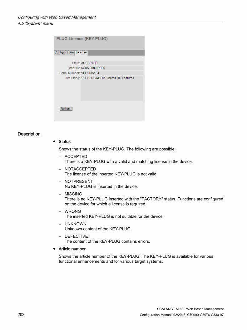
Configuring with Web Based Management 4.5 "System" menu
SCALANCE M-800 Web Based Management 202 Configuration Manual, 02/2018, C79000-G8976-C330-07
Description ● Status
Shows the status of the KEY-PLUG. The following are possible:
– ACCEPTED There is a KEY-PLUG with a valid and matching license in the device.
– NOTACCEPTED The license of the inserted KEY-PLUG is not valid.
– NOTPRESENT No KEY-PLUG is inserted in the device.
– MISSING There is no KEY-PLUG inserted with the "FACTORY" status. Functions are configured on the device for which a license is required.
– WRONG The inserted KEY-PLUG is not suitable for the device.
– UNKNOWN Unknown content of the KEY-PLUG.
– DEFECTIVE The content of the KEY-PLUG contains errors.
● Article number
Shows the article number of the KEY-PLUG. The KEY-PLUG is available for various functional enhancements and for various target systems.

Configuring with Web Based Management 4.5 "System" menu
SCALANCE M-800 Web Based Management Configuration Manual, 02/2018, C79000-G8976-C330-07 203
● Serial Number
Shows the serial number of the KEY-PLUG.
● Info String
Shows additional information about the device that used the KEY-PLUG previously, for example, article number, type designation, and the versions of the hardware and software. The displayed software version corresponds to the version in which the configuration was last changed. With the "NOT ACCEPTED" status, further information on the cause of the problem is displayed.
Note
When you save the configuration, the information about whether or not a KEY-PLUG was inserted in the device at the time is also saved. This configuration can then only work if a KEY-PLUG with the same order number / license is inserted.
4.5.14 Ping
Reachability of an address in an IPv4 network With the ping function, you can check whether a certain IPv4 address is reachable in the network.
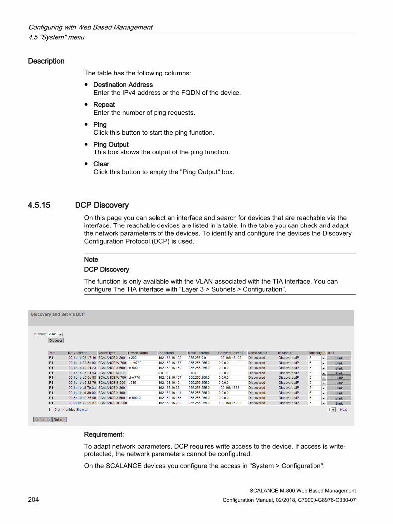
Configuring with Web Based Management 4.5 "System" menu
SCALANCE M-800 Web Based Management 204 Configuration Manual, 02/2018, C79000-G8976-C330-07
Description The table has the following columns:
● Destination Address Enter the IPv4 address or the FQDN of the device.
● Repeat Enter the number of ping requests.
● Ping Click this button to start the ping function.
● Ping Output This box shows the output of the ping function.
● Clear Click this button to empty the "Ping Output" box.
4.5.15 DCP Discovery On this page you can select an interface and search for devices that are reachable via the interface. The reachable devices are listed in a table. In the table you can check and adapt the network parameterrs of the devices. To identify and configure the devices the Discovery Configuration Protocol (DCP) is used.
Note DCP Discovery
The function is only available with the VLAN associated with the TIA interface. You can configure The TIA interface with "Layer 3 > Subnets > Configuration".
Requirement:
To adapt network parameters, DCP requires write access to the device. If access is write-protected, the network parameters cannot be configutred.
On the SCALANCE devices you configure the access in "System > Configuration".
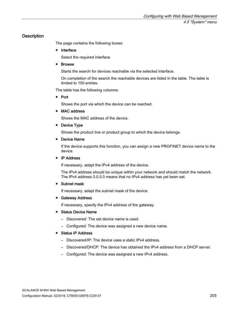
Configuring with Web Based Management 4.5 "System" menu
SCALANCE M-800 Web Based Management Configuration Manual, 02/2018, C79000-G8976-C330-07 205
Description The page contains the following boxes:
● Interface
Select the required interface.
● Browse
Starts the search for devices reachable via the selected interface.
On completion of the search the reachable devices are listed in the table. The table is limited to 100 entries.
The table has the following columns:
● Port
Shows the port via which the device can be reached.
● MAC address
Shows the MAC address of the device.
● Device Type
Shows the product line or product group to which the device belongs.
● Device Name
If the device supports this function, you can assign a new PROFINET device name to the device.
● IP Address
If necessary, adapt the IPv4 address of the device.
The IPv4 address should be unique within your network and should match the network. The IPv4 address 0.0.0.0 means that no IPv4 address has yet been set.
● Subnet mask
If necessary, adapt the subnet mask of the device.
● Gateway Address
If necessary, specify the IPv4 address of the gateway.
● Status Device Name
– Discovered: The set device name is used.
– Configured: The device was assigned a new device name.
● Status IP Address
– Discovered/IP: The device uses a static IPv4 address.
– Discovered/DHCP: The device has obtained the IPv4 address from a DHCP server.
– Configured: The device was assigned a new IPv4 address.

Configuring with Web Based Management 4.5 "System" menu
SCALANCE M-800 Web Based Management 206 Configuration Manual, 02/2018, C79000-G8976-C330-07
● Timeout
Specify the time for flashing. When the time elapses, flashing stops.
● Flash
Makes the port LEDs of the selected device flash.
4.5.16 SMS
4.5.16.1 General
For the device to be able to send an SMS message, you need to enter a specific SMS center (Short Message Server Center, SMS-C) of your mobile wireless provider or your service provider.
● If you use the standard SMS center, you do not need to configure anything on this WBM page. The SIM card already contains the correct information.
● If you do not use the standard SMS center, you can replace the stored call number of the standard SMS center with another number on this WBM page. This depends on your contract.
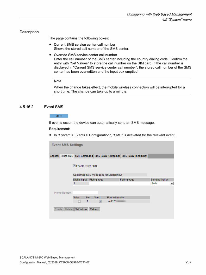
Configuring with Web Based Management 4.5 "System" menu
SCALANCE M-800 Web Based Management Configuration Manual, 02/2018, C79000-G8976-C330-07 207
Description The page contains the following boxes:
● Current SMS service center call number Shows the stored call number of the SMS center.
● Override SMS service center call number Enter the call number of the SMS center including the country dialing code. Confirm the entry with "Set Values" to store the call number on the SIM card. If the call number is displayed in "Current SMS service center call number", the stored call number of the SMS center has been overwritten and the input box emptied.
Note
When the change takes effect, the mobile wireless connection will be interrupted for a short time. The change can take up to a minute.
4.5.16.2 Event SMS
If events occur, the device can automatically send an SMS message.
Requirement:
● In "System > Events > Configuration", "SMS" is activated for the relevant event.

Configuring with Web Based Management 4.5 "System" menu
SCALANCE M-800 Web Based Management 208 Configuration Manual, 02/2018, C79000-G8976-C330-07
Description The page contains the following:
● Enable Event SMS When enabled, the device sends an SMS message.
In the area "Customize SMS messages for Digital Input" you specify the SMS text for the digital input.
● Digital input
Shows the available digital inputs.
● Rising edge
Enter the SMS text that is sent when the signal at the digital input changes from 0 (LOW) to 1 (HIGH).
● Falling edge
Enter the SMS text that is sent when the signal at the digital input changes from 1 (HIGH) to 0 (LOW).
Note Characters permitted for the SMS text
The following characters are permitted in the text: • 0123456789 • A...Z a...z • Space • ! % & / ( ) = * + < > ' , . -
Configuring with Web Based Management 4.5 "System" menu
SCALANCE M-800 Web Based Management Configuration Manual, 02/2018, C79000-G8976-C330-07 209
● Sending Option
Specify when the SMS text is sent.
– None
The function is disabled.
– Both
In both cases, an SMS text is sent.
– Rising only
Only the SMS text is sent when the signal at the digital input changes from 0 (LOW) to 1 (HIGH).
– Falling only
Only the SMS text is sent when the signal at the digital input changes from 1 (HIGH) to 0 (LOW).
● Phone Number Enter the full telephone number of the recipient including the country dialing code If you click the "Create" button, a new row with a unique number is created.
● This table contains the following columns:
– Select Activate the check box in the row to be deleted.
– No. Unique number that is assigned when the sender is created.
– Send Specify whether the device sends an SMS message to this recipient.
– Phone Number Shows the phone number of the recipient.
Procedure Configuring an event SMS
To obtain an SMS message when the signal changes from 0 (LOW) to 1 (HIGH), follow the steps below.
1. Specify the SMS text at "Rising Edge".
2. For "Sending Option", select "Rising only".
3. Click the "Set Values" button.
4. Enter the phone number of the recipient in the "Phone Number" input box.
5. Click the "Create" button. A new row with a unique number is created in the table.
6. Specify whether the device sends an SMS message to this recipient if a fault occurs.
7. Select "Enable Event SMS".
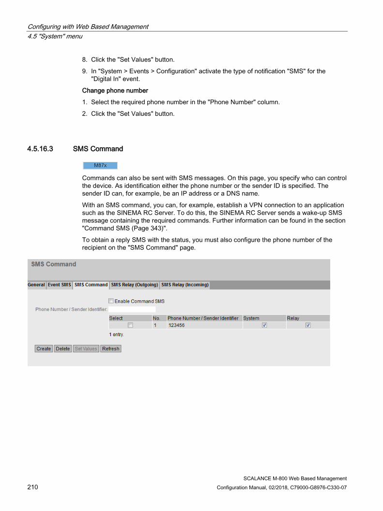
Configuring with Web Based Management 4.5 "System" menu
SCALANCE M-800 Web Based Management 210 Configuration Manual, 02/2018, C79000-G8976-C330-07
8. Click the "Set Values" button.
9. In "System > Events > Configuration" activate the type of notification "SMS" for the "Digital In" event.
Change phone number
1. Select the required phone number in the "Phone Number" column.
2. Click the "Set Values" button.
4.5.16.3 SMS Command
Commands can also be sent with SMS messages. On this page, you specify who can control the device. As identification either the phone number or the sender ID is specified. The sender ID can, for example, be an IP address or a DNS name.
With an SMS command, you can, for example, establish a VPN connection to an application such as the SINEMA RC Server. To do this, the SINEMA RC Server sends a wake-up SMS message containing the required commands. Further information can be found in the section "Command SMS (Page 343)".
To obtain a reply SMS with the status, you must also configure the phone number of the recipient on the "SMS Command" page.
Configuring with Web Based Management 4.5 "System" menu
SCALANCE M-800 Web Based Management Configuration Manual, 02/2018, C79000-G8976-C330-07 211
Description The page contains the following:
● Enable Command SMS Enable or disable receipt of command SMS messages.
● Phone Number / Sender Identifier Specify the sender ID or the phone number including the country code. If you click the "Create" button, a new row with a unique number is created.
For phone numbers, you can replace any numbers with the asterisk (*) placeholder. The placeholder can only be positioned at the end of a number sequence.
Example:
+49144545* stands for all phone numbers that start with 0177545.
Note
Please note that when you use the placeholder "*", command text messages (SMS) from a wide range of phone numbers will be accepted. We therefore recommend that you use a more restrictive input, if possible.
This table contains the following columns:
● Select Activate the check box in the row to be deleted.
● No. Shows the unique number of the entry.
● Phone Number / Sender Identifier Shows the sender ID or the phone number.
● System / Relay Specify which class (System / Relay) of commands is accepted from this sender. Further information can be found in the section "Command SMS (Page 343)"
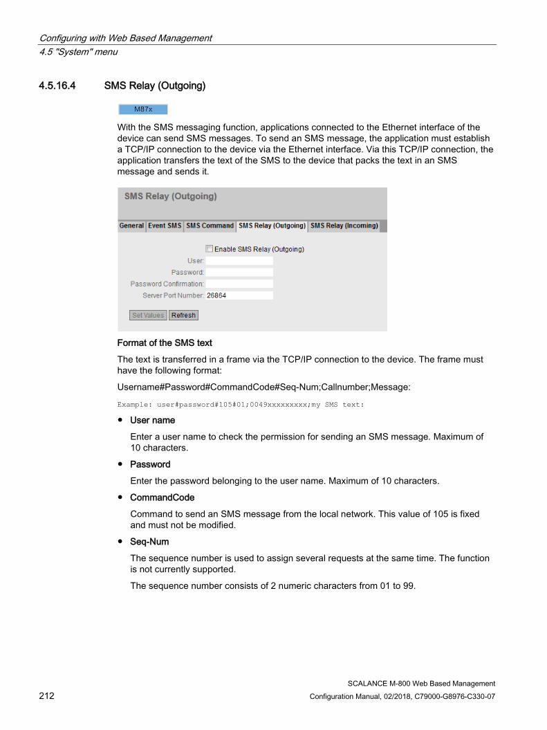
Configuring with Web Based Management 4.5 "System" menu
SCALANCE M-800 Web Based Management 212 Configuration Manual, 02/2018, C79000-G8976-C330-07
4.5.16.4 SMS Relay (Outgoing)
With the SMS messaging function, applications connected to the Ethernet interface of the device can send SMS messages. To send an SMS message, the application must establish a TCP/IP connection to the device via the Ethernet interface. Via this TCP/IP connection, the application transfers the text of the SMS to the device that packs the text in an SMS message and sends it.
Format of the SMS text
The text is transferred in a frame via the TCP/IP connection to the device. The frame must have the following format:
Username#Password#CommandCode#Seq-Num;Callnumber;Message:
Example: user#password#105#01;0049xxxxxxxxx;my SMS text:
● User name
Enter a user name to check the permission for sending an SMS message. Maximum of 10 characters.
● Password
Enter the password belonging to the user name. Maximum of 10 characters.
● CommandCode
Command to send an SMS message from the local network. This value of 105 is fixed and must not be modified.
● Seq-Num
The sequence number is used to assign several requests at the same time. The function is not currently supported.
The sequence number consists of 2 numeric characters from 01 to 99.

Configuring with Web Based Management 4.5 "System" menu
SCALANCE M-800 Web Based Management Configuration Manual, 02/2018, C79000-G8976-C330-07 213
● Call number
Call number of the SMS recipient with a maximum of 40 characters. International numbers (+49) are permitted.
● Message
SMS text with a maximum of 160 characters
Note Characters permitted for sending SMS messages
The following characters are permitted in the text: • 0123456789 • A...Z a...z • Space • ! " % & / ( ) = ? * + < > ' , . -
Description The page contains the following:
● Enable SMS Relay (Outgoing) Enable or disable the sending of SMS messages from the local network.
● User Enter the user name that must be included before the text is sent as an SMS message.
● Password Enter the password that must be included before the text is sent as an SMS message.
● Password (Confirmation) Repeat the password to confirm it.
● Server Port Number Enter the port at which the server receives the SMS.
4.5.16.5 SMS Relay (Incoming)
Applications connected to the Ethernet interface of the device can receive SMS messages. To receive an SMS message, the application must establish a TCP/IP connection to the device via the Ethernet interface. The device receives a command SMS message and forwards the text it contains to the application.

Configuring with Web Based Management 4.5 "System" menu
SCALANCE M-800 Web Based Management 214 Configuration Manual, 02/2018, C79000-G8976-C330-07
Format of the SMS text
The text is sent in a frame via the TCP/IP connection to the application. The frame must have the following format:
Username#Password#CommandCode#Seq-Num;Callnumber;Message:
Example: user#password#105#01;0049xxxxxxxxx;my SMS text:
● User name
Enter a user name to check the receipt of the SMS message. Maximum of 10 characters.
● Password
Enter the password belonging to the user name. Maximum of 10 characters.
● CommandCode
Command to send an SMS message to the local network. This value of 105 is fixed.
● Seq-Num
The sequence number is used to assign several requests at the same time. The function is not currently supported.
The sequence number consists of 2 numeric characters from 01 to 99.
Configuring with Web Based Management 4.5 "System" menu
SCALANCE M-800 Web Based Management Configuration Manual, 02/2018, C79000-G8976-C330-07 215
● Call number
Phone number of the sender of the command SMS message with a maximum of 40 characters. International numbers (+49) are permitted.
● Message
SMS text with a maximum of 160 characters
Note Characters permitted for sending SMS messages
The following characters are permitted in the text: • 0123456789 • A...Z a...z • Space • ! " % & / ( ) = ? * + < > ' , . -
Description The page contains the following:
● Connection Name Enter a unique name for the relay connection.
● IP Address Enter the IP address of the recipient. The frame is sent to this IP address.
● Port number Enter the port to which the frame will be sent.
● Username Enter the user name to check receipt of the message. Enter the user name in the frame.
● Password Enter the password belonging to the user name.
● Password (Confirmation) Repeat the password to confirm it.
This table contains the following columns:
● Select Activate the check box in the row to be deleted.
● Connection Name Shows the name of the relay connection.
● IP Address Shows the IP address of the recipient.
● Port Number Shows the port.
● Username Shows the user name contained in the frame.
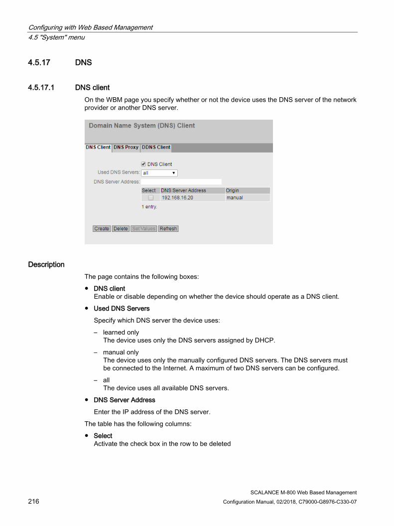
Configuring with Web Based Management 4.5 "System" menu
SCALANCE M-800 Web Based Management 216 Configuration Manual, 02/2018, C79000-G8976-C330-07
4.5.17 DNS
4.5.17.1 DNS client On the WBM page you specify whether or not the device uses the DNS server of the network provider or another DNS server.
Description The page contains the following boxes:
● DNS client Enable or disable depending on whether the device should operate as a DNS client.
● Used DNS Servers
Specify which DNS server the device uses:
– learned only The device uses only the DNS servers assigned by DHCP.
– manual only The device uses only the manually configured DNS servers. The DNS servers must be connected to the Internet. A maximum of two DNS servers can be configured.
– all The device uses all available DNS servers.
● DNS Server Address
Enter the IP address of the DNS server.
The table has the following columns:
● Select Activate the check box in the row to be deleted
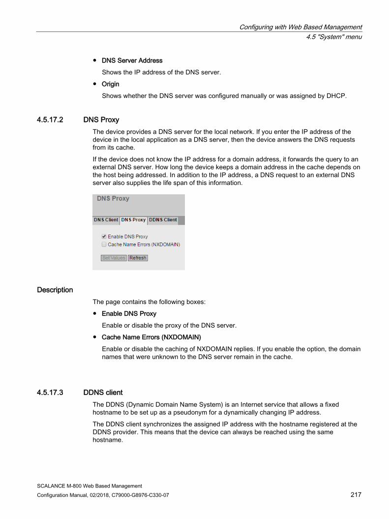
Configuring with Web Based Management 4.5 "System" menu
SCALANCE M-800 Web Based Management Configuration Manual, 02/2018, C79000-G8976-C330-07 217
● DNS Server Address
Shows the IP address of the DNS server.
● Origin
Shows whether the DNS server was configured manually or was assigned by DHCP.
4.5.17.2 DNS Proxy The device provides a DNS server for the local network. If you enter the IP address of the device in the local application as a DNS server, then the device answers the DNS requests from its cache.
If the device does not know the IP address for a domain address, it forwards the query to an external DNS server. How long the device keeps a domain address in the cache depends on the host being addressed. In addition to the IP address, a DNS request to an external DNS server also supplies the life span of this information.
Description The page contains the following boxes:
● Enable DNS Proxy
Enable or disable the proxy of the DNS server.
● Cache Name Errors (NXDOMAIN)
Enable or disable the caching of NXDOMAIN replies. If you enable the option, the domain names that were unknown to the DNS server remain in the cache.
4.5.17.3 DDNS client The DDNS (Dynamic Domain Name System) is an Internet service that allows a fixed hostname to be set up as a pseudonym for a dynamically changing IP address.
The DDNS client synchronizes the assigned IP address with the hostname registered at the DDNS provider. This means that the device can always be reached using the same hostname.
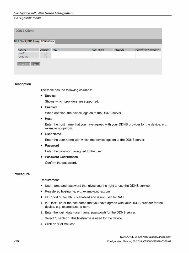
Configuring with Web Based Management 4.5 "System" menu
SCALANCE M-800 Web Based Management 218 Configuration Manual, 02/2018, C79000-G8976-C330-07
Description The table has the following columns:
● Service
Shows which providers are supported.
● Enabled
When enabled, the device logs on to the DDNS server.
● Host
Enter the host name that you have agreed with your DDNS provider for the device, e.g. example.no-ip-com.
● User Name
Enter the user name with which the device logs on to the DDNS server.
● Password
Enter the password assigned to the user.
● Password Confirmation
Confirm the password.
Procedure Requirement:
● User name and password that gives you the right to use the DDNS service.
● Registered hostname, e.g. example.no-ip.com
● UDP port 53 for DNS is enabled and is not used for NAT.
1. In "Host", enter the hostname that you have agreed with your DDNS provider for the device, e.g. example.no-ip-com.
2. Enter the login data (user name, password) for the DDNS server.
3. Select "Enabled". This hostname is used for the device.
4. Click on "Set Values".
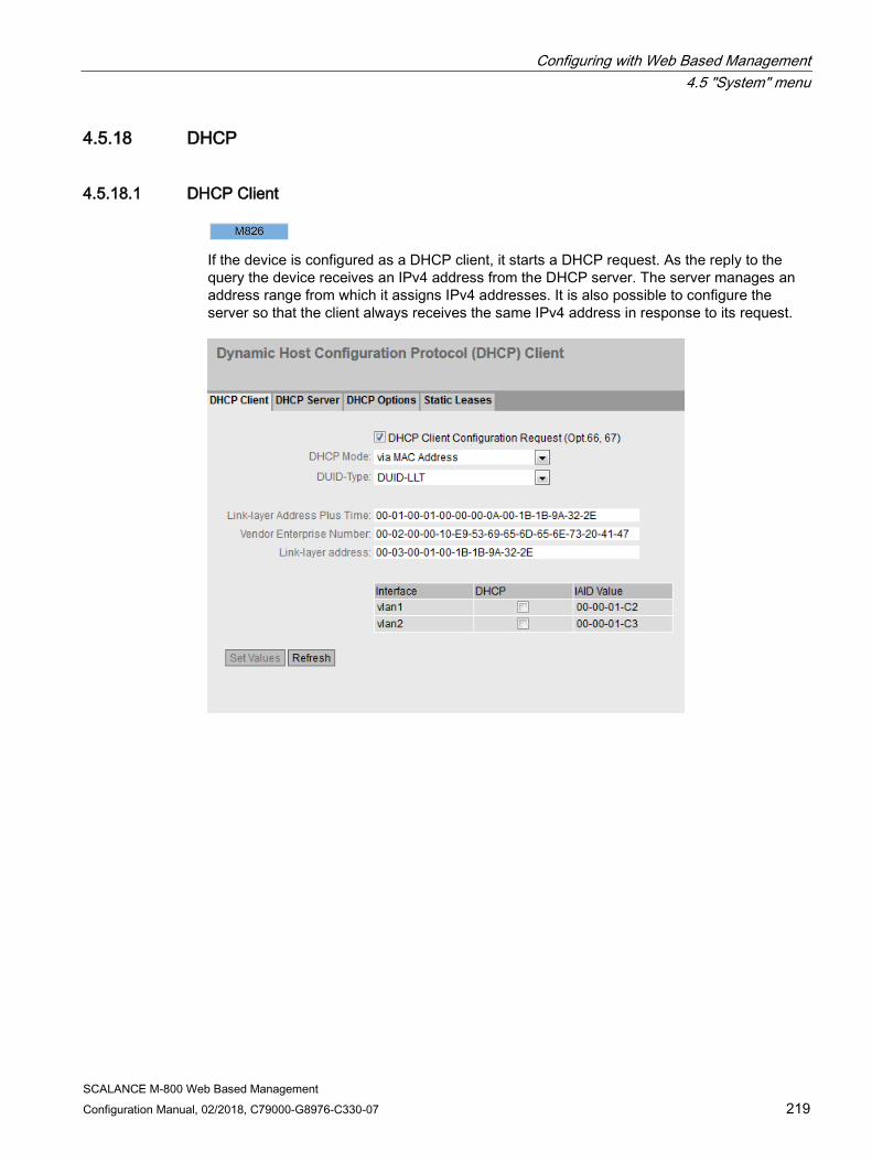
Configuring with Web Based Management 4.5 "System" menu
SCALANCE M-800 Web Based Management Configuration Manual, 02/2018, C79000-G8976-C330-07 219
4.5.18 DHCP
4.5.18.1 DHCP Client
If the device is configured as a DHCP client, it starts a DHCP request. As the reply to the query the device receives an IPv4 address from the DHCP server. The server manages an address range from which it assigns IPv4 addresses. It is also possible to configure the server so that the client always receives the same IPv4 address in response to its request.
Configuring with Web Based Management 4.5 "System" menu
SCALANCE M-800 Web Based Management 220 Configuration Manual, 02/2018, C79000-G8976-C330-07
Description The page contains the following boxes:
● DHCP Client Configuration Request (Opt. 66, 67) When enabled, the DHCP client uses the options to download the configuration file (option 67) from the TFTP server (option 66). After the restart, the device uses the data from the configuration file.
Note
Configuration file and firmware version
The configuration file is used to store and read in configuration data within a firmware version, e.g. 4.3. Configuration files created with a firmware version <4.2 cannot be read in to a device with a firmware version 4.3.
● DHCP Mode Specify the type of identifier with which the DHCP client logs on with its DHCP server.
– via MAC Address Identification is based on the MAC address.
– via DHCP Client ID Identification is based on a freely defined DHCP client ID.
– Via System Name Identification is based on the system name. If the system name is 255 characters long, the last character is not used for identification.
– via Iaid and Duid
With this the DHCP client can log on with DHCP servers that support parallel operation of IPv4 and IPv6.
The identification is via the IAID and the DUID and identifies precisely one IP interface of the device.
IAID (Interface Association Identifier): At least one IAID is generated for each IP interface The IAID remains unchanged when the DHCP client restarts
DUID (DHCP Unique Identifier): Uniquely identifies server and clients and applies to all IP interfaces of the device. The DUID remains unchanged when there is a restart. Unless the user changes this.
Note
DHCP mode "via PROFINET device name"
With firmware version 5.0, the setting "via PROFINET device name" was removed.
Configuring with Web Based Management 4.5 "System" menu
SCALANCE M-800 Web Based Management Configuration Manual, 02/2018, C79000-G8976-C330-07 221
● DUID-Type
Specify which DUID type will be used. The DUID types are defined in RFC 3315.
– DUID-LLT
DUID is based on the link layer address of the interface and a time stamp
– DUID-EN
DUID is assigned by the vendor (EN = enterprise number)
– DUID-LL
DUID is based on the link layer address of the interface
● Link-layer Address Plus Time (LLT)
The value is based on the link layer address of the interface and a time stamp. The value is regenerated each time the factory settings are restored. When necessary the value can be changed.
● Vendor Enterprise Number (EN)
The value is based on the enterprise number specific to the vendor. The value is regenerated each time the factory settings are restored. When necessary the value can be changed.
● Link-layer address (LL)
The link layer address is based on the MAC address. The value is regenerated each time the factory settings are restored. When necessary the value can be changed.
The table has the following columns:
● Interface Interface to which the setting relates.
● DHCP Enable or disable the DHCP client for the relevant interface.
● IAID Value
Value with which the interface (DHCP client) identifies itself with the DHCP server.
Procedure Follow the steps below to configure the IP address using the DHCP client ID:
1. Select the identification method in the "DHCP Mode" drop-down list.
If you select the DHCP mode "via DHCP Client ID" an input box appears.
In the enabled input box "DHCP client ID" enter a string to identify the device. This is then evaluated by the DHCP server.
2. Select the "DHCP Client Configuration Request (Opt. 66, 67)", if you want the DHCP client to use options 66 and 67 to download and then enable a configuration file.

Configuring with Web Based Management 4.5 "System" menu
SCALANCE M-800 Web Based Management 222 Configuration Manual, 02/2018, C79000-G8976-C330-07
3. Enable the "DHCP" option in the table.
4. Click the "Set Values" button.
Note
If a configuration file is downloaded, this can trigger a system restart. If the currently running configuration and the configuration in the downloaded configuration file differ, the system restarts.
Make sure that the option "DHCP Client Configuration Request (Opt. 66, 67)" is no longer set.
4.5.18.2 DHCP Server You can operate the device as a DHCP server. This allows IP addresses to be assigned automatically to the connected devices. The IP addresses are either distributed dynamically from an address band (pool) you have specified or a specific IP address is assigned to a particular device.
On this page, specify the address band from which the device receives any IP address. You configure the static assignment of the IP addresses in "Static Leases".
Requirement ● The connected devices are configured so that they obtain the IP address from a DHCP
server.

Configuring with Web Based Management 4.5 "System" menu
SCALANCE M-800 Web Based Management Configuration Manual, 02/2018, C79000-G8976-C330-07 223
Description The page contains the following boxes:
● Enable DHCP Server
Enable or disable the DHCP server on the device.
Note
To avoid conflicts with IPv4 addresses, only one device may be configured as a DHCP server in the network.
● Probe address with ICMP echo before offer
When selected, the DHCP server checks whether or not the IP address has already been assigned. To do this the DHCP server sends ICMP echo messages (ping) to the IPv4 address. If no reply is received, the DHCP server can assign the IPv4 address.
Note
If there are devices in your network on which the echo service is disabled as default, there may be conflicts with the IPv4 addresses. To avoid this, assign these devices an IPv4 address outside the IPv4 address band.
The table has the following columns:
● Select
Select the check box in the row to be deleted.
● Pool ID
Shows the number of the IPv4 address band. If you click the "Create" button, a new row with a unique number is created (pool ID).
● Interface
Select a VLAN IP interface. The IPv4 addresses are assigned dynamically via this interface.
The requirement for the assignment is that the IPv4 address of the interface is located in the subnet of the IPv4 address band. If this is not the case, the interface does not assign any IPv4 addresses.
● Enable
Specify whether or not this IPv4 address band will be used.
Note
If you enable the IPv4 address band, its settings in this and the other DHCP tabs are grayed out and can no longer be edited.
● Subnet
Enter the network address range that will be assigned to the devices. Use the CIDR notation.
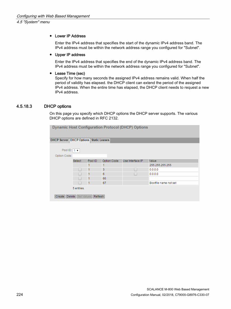
Configuring with Web Based Management 4.5 "System" menu
SCALANCE M-800 Web Based Management 224 Configuration Manual, 02/2018, C79000-G8976-C330-07
● Lower IP Address
Enter the IPv4 address that specifies the start of the dynamic IPv4 address band. The IPv4 address must be within the network address range you configured for "Subnet".
● Upper IP address
Enter the IPv4 address that specifies the end of the dynamic IPv4 address band. The IPv4 address must be within the network address range you configured for "Subnet".
● Lease Time (sec) Specify for how many seconds the assigned IPv4 address remains valid. When half the period of validity has elapsed. the DHCP client can extend the period of the assigned IPv4 address. When the entire time has elapsed, the DHCP client needs to request a new IPv4 address.
4.5.18.3 DHCP options On this page you specify which DHCP options the DHCP server supports. The various DHCP options are defined in RFC 2132.

Configuring with Web Based Management 4.5 "System" menu
SCALANCE M-800 Web Based Management Configuration Manual, 02/2018, C79000-G8976-C330-07 225
Description The page contains the following boxes:
● Pool ID
Select the required address band.
● Option Code
Enter the number of the required DHCP option.
Note DHCP options supported
The DHCP options 1, 2, 3. 4. 5, 6, 42, 66, 67 are supported.
The DHCP options 1, 3, 6, 66 and 67 are created automatically when the IPv4 address band is created. With the exception of option 1, the options can be deleted.
The table has the following columns:
● Select
Select the check box in the row to be deleted
● Pool ID
Shows the number of the address band.
● Option Code
Shows the number of the DHCP option.

Configuring with Web Based Management 4.5 "System" menu
SCALANCE M-800 Web Based Management 226 Configuration Manual, 02/2018, C79000-G8976-C330-07
● Use Interface IP
Specify whether or not the internal IP address of the device will be used.
● Value Enter the DHCP parameter that is transferred to the DHCP client. The content depends on the DHCP option.
Value Option name 1 Subnet Mask The subnet mask is entered
automatically. Option cannot be deleted.
2 Offset time Offset time to the coordinated universal time UTC.
Enter the offset time in seconds in hexadecimal format.
3 Router The IPv4 address for router in the subnet of the DHCP client. If the device itself is the router, the IPv4 address of the interface is used.
You can specify several IPv4 ad-dresses separated by commas.
4 Time server The IPv4 address of the time server available to the DHCP client.
5 Name server The IPv4 address of the name server available to the DHCP client.
6 DNS Server The IPv4 address of the DNS server available to the DHCP client. If the device itself is the DNS server, the IPv4 address of the interface is used.
42 NTP Server The IPv4 address of the NTP server available to the DHCP client.
66 TFTP server The IPv4 address or the host-name of the TFTP server availa-ble to the DHCP client.
Enter the address of the TFTP server.
67 Name of the boot file
The name of the boot file that the client downloads from the TFTP server.
Enter the name of the boot file in the string format.
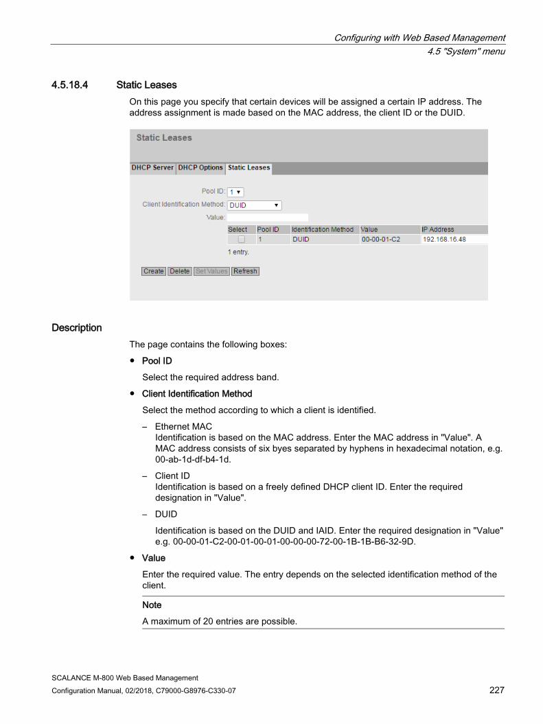
Configuring with Web Based Management 4.5 "System" menu
SCALANCE M-800 Web Based Management Configuration Manual, 02/2018, C79000-G8976-C330-07 227
4.5.18.4 Static Leases On this page you specify that certain devices will be assigned a certain IP address. The address assignment is made based on the MAC address, the client ID or the DUID.
Description The page contains the following boxes:
● Pool ID
Select the required address band.
● Client Identification Method
Select the method according to which a client is identified.
– Ethernet MAC Identification is based on the MAC address. Enter the MAC address in "Value". A MAC address consists of six byes separated by hyphens in hexadecimal notation, e.g. 00-ab-1d-df-b4-1d.
– Client ID Identification is based on a freely defined DHCP client ID. Enter the required designation in "Value".
– DUID
Identification is based on the DUID and IAID. Enter the required designation in "Value" e.g. 00-00-01-C2-00-01-00-01-00-00-00-72-00-1B-1B-B6-32-9D.
● Value
Enter the required value. The entry depends on the selected identification method of the client.
Note
A maximum of 20 entries are possible.

Configuring with Web Based Management 4.5 "System" menu
SCALANCE M-800 Web Based Management 228 Configuration Manual, 02/2018, C79000-G8976-C330-07
The table has the following columns:
● Select
Select the check box in the row to be deleted.
● Pool ID
Shows the number of the address band.
● Identification Method
Shows the method with which the client identifies itself with the DHCP server.
● Value Shows the MAC address or client ID or DUID of the client.
● IP Address
Specify the IPv4 address that will be assigned to the client. The IPv4 address must be within the address band.
4.5.19 cRSP / SRS
Note
Common Remote Service Platform (cRSP) / Siemens Remote Service (SRS) is a remote maintenance platform via which remote maintenance access is possible.
To use the platform, additional service contracts are necessary and certain constraints must be kept to. If you are interested in cRSP / SRS, call your local Siemens contact or visit Web page (https://support.industry.siemens.com/cs/ww/en/sc/2281).
On this page, you configure the access data for the SRS / cRSP acc. to URI syntax. The Uniform Resource Identifier (URI) is defined in RFC 3986.
Configuring with Web Based Management 4.5 "System" menu
SCALANCE M-800 Web Based Management Configuration Manual, 02/2018, C79000-G8976-C330-07 229
Description The page contains the following boxes:
● Enable DDNS for cRSP / SRS
Enable or disable the use of cRSP / SRS.
● Update Interval
Enter the time interval.
● Validate Server Certificate
When enabled, the device checks the validity of the received server certificate.
The table has the following columns:
● Index
The number of the entry.
● Select
Select the check box in the row to be deleted. Click "Delete" to delete the entry.
● Scheme
Identifies the access method and the resource type.
https: Secure access to a Web page.
● Authority
Contains the address of the destination server
● Path
Contains the target path to the resource. The target path can correspond to a directory name or file name.
● Query
A query can contain parameter values for an application.
– WAN_IP (keyword): Replaces WAN_IP with current external IP address of the device to the destination server.
● Frag.
Addresses local parts of the resource, e.g. the anchor attribute of a Web page.
● Status
Shows the status of the last cRSP / SRS access of the entry.
● Enabled
When enabled, this entry is used.

Configuring with Web Based Management 4.5 "System" menu
SCALANCE M-800 Web Based Management 230 Configuration Manual, 02/2018, C79000-G8976-C330-07
4.5.20 Proxy Server On this WBM page, you configure the proxy server that is used by various components, for example SINEMA RC.
Description ● Proxy Name
Enter a name for the proxy server.
The table has the following columns:
● Select
Select the check box in the row to be deleted. Click "Delete" to delete the entry.
● Name
Shows the name of the proxy server.
● Address
Enter the IPv4 address of the proxy server.
● Type
Specify the type of the proxy server.
– HTTP: Proxy server only for access using HTTP.
– SOCKS: Universal proxy server
● Port
Enter the port on which the proxy service runs.
● Auth. Method
Specify the authentication method.
– None Without authentication
– Basic Standard authentication. User name and password are sent unencrypted.
– NTML (NT LAN Manager) Authentication according to the NTML standard (Windows user logon)

Configuring with Web Based Management 4.5 "System" menu
SCALANCE M-800 Web Based Management Configuration Manual, 02/2018, C79000-G8976-C330-07 231
● User Name
Enter the user name for access to the proxy server.
● Password
Enter the password for access to the proxy server.
● Password Confirmation
Enter the password again to confirm it.
4.5.21 SINEMA RC
On the WBM page, you configure the access to the SINEMA RC server.
Note
This function can only be used with a KEY PLUG (Page 34).
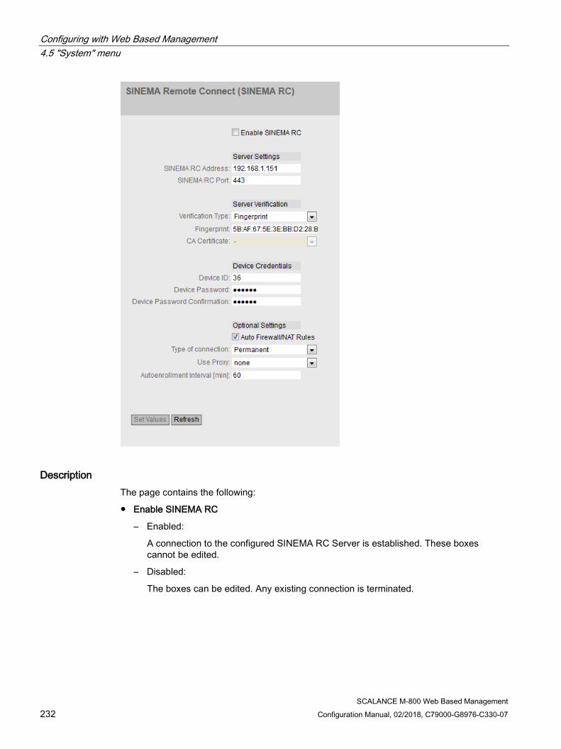
Configuring with Web Based Management 4.5 "System" menu
SCALANCE M-800 Web Based Management 232 Configuration Manual, 02/2018, C79000-G8976-C330-07
Description The page contains the following:
● Enable SINEMA RC
– Enabled:
A connection to the configured SINEMA RC Server is established. These boxes cannot be edited.
– Disabled:
The boxes can be edited. Any existing connection is terminated.

Configuring with Web Based Management 4.5 "System" menu
SCALANCE M-800 Web Based Management Configuration Manual, 02/2018, C79000-G8976-C330-07 233
"Server settings" area
● SINEMA RC Address
Enter the IPv4 address or the DNS host name of the SINEMA RC Server.
● SINEMA RC Port
Enter the port via which the SINEMA RC Server can be reached.
"Server Verification" area
● Verification Type
– Fingerprint: The identity of the server is verified based on the fingerprint.
– CA certificate: The identity of the server is verified based on the CA certificate.
● Fingerprint
Only necessary with the setting "Fingerprint". Enter the fingerprint of the device. The fingerprint is assigned during commissioning of the SINEMA RC Server. Based on the fingerprint, the device checks whether the correct SINEMA RC Server is involved. You will find further information on this in the Operating Instructions of the SINEMA RC Server.
● CA Certificate
Only necessary with the setting "CA Certificate". Select the CA certificate of the server used to sign the server certificate. Only loaded CA certificates can be selected.
"Device Credentials" area
● Device ID
Enter the device ID. The device ID is assigned when configuring the device on the SINEMA RC Server. You will find further information on this in the Operating Instructions of the SINEMA RC Server.
● Device Password
Enter the password with which the device logs on to the SINEMA RC Server. The password is assigned when configuring the device on the SINEMA RC Server. You will find further information on this in the Operating Instructions of the SINEMA RC Server.
● Device Password Confirmation
Repeat the password.

Configuring with Web Based Management 4.5 "System" menu
SCALANCE M-800 Web Based Management 234 Configuration Manual, 02/2018, C79000-G8976-C330-07
"Optional Settings" area
● Auto Firewall/NAT Rules
– Enabled
The firewall and NAT rules are created automatically for the VPN connection. The connections between the configured exported subnets and the subnets that can be reached via the SINEMA RC Server are allowed. The NAT settings are implemented as configured in the SINEMA RC Server.
– Disabled
You will need to create the firewall and NAT rules yourself.
● Type of connection
Specify the type of VPN connection. For more detailed information, refer to the section "VPN connection establishment".
– Auto
The device adopts the settings of the SINEMA RC Server. You configure the settings on the SINEMA RC Server in "Remote connections > Devices". You will find further information on this topic in the operating instructions "SINEMA RC Server".
– Permanent
The settings of the SINEMA RC Server are ignored. The device establishes a VPN connection to the SINEMA RC Server. The VPN tunnel is established permanently
– Wake-up SMS (only with M87x)
The settings of the SINEMA RC Server are ignored. When the device receives a command SMS message (wake-up SMS message), it attempts to establish a connection to the SINEMA RC Server. On condition that in "System > SMS > SMS Command" it is specified who a command SMS of the class "System" will be accepted from.
– Digital Input
The settings of the SINEMA RC Server are ignored. If the "Digital In" event occurs, the device attempts to establish a VPN connection to the SINEMA RC Server. This is on condition that the event "Digital Input" is forwarded to the VPN connection. To do this in "System > Events> Configuration" activate "VPN Tunnel" for the "Digital In" event.
– Digital In & Wake-up SMS (only with M87x)
The settings of the SINEMA RC Server are ignored. If the "Digital In" event occurs or when the device receives an SMS command, it attempts to establish a VPN connection to the SINEMA RC Server.
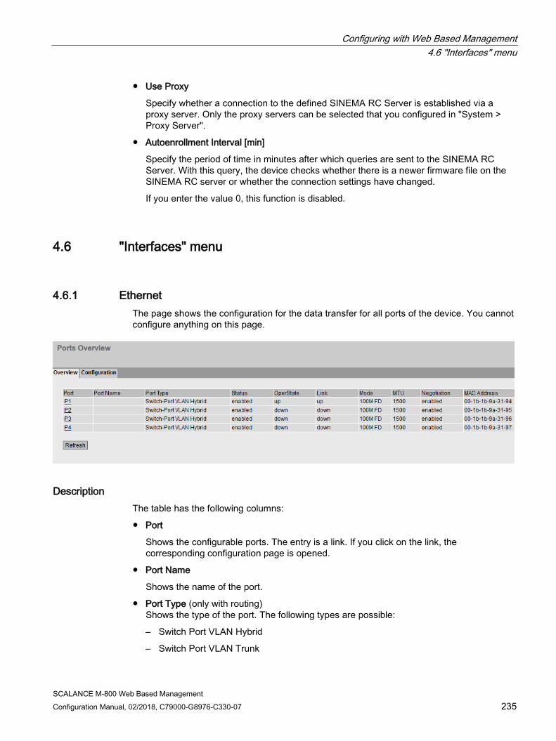
Configuring with Web Based Management 4.6 "Interfaces" menu
SCALANCE M-800 Web Based Management Configuration Manual, 02/2018, C79000-G8976-C330-07 235
● Use Proxy
Specify whether a connection to the defined SINEMA RC Server is established via a proxy server. Only the proxy servers can be selected that you configured in "System > Proxy Server".
● Autoenrollment Interval [min]
Specify the period of time in minutes after which queries are sent to the SINEMA RC Server. With this query, the device checks whether there is a newer firmware file on the SINEMA RC server or whether the connection settings have changed.
If you enter the value 0, this function is disabled.
4.6 "Interfaces" menu
4.6.1 Ethernet The page shows the configuration for the data transfer for all ports of the device. You cannot configure anything on this page.
Description The table has the following columns:
● Port
Shows the configurable ports. The entry is a link. If you click on the link, the corresponding configuration page is opened.
● Port Name
Shows the name of the port.
● Port Type (only with routing) Shows the type of the port. The following types are possible:
– Switch Port VLAN Hybrid
– Switch Port VLAN Trunk

Configuring with Web Based Management 4.6 "Interfaces" menu
SCALANCE M-800 Web Based Management 236 Configuration Manual, 02/2018, C79000-G8976-C330-07
● Status
Shows whether the port is on or off. Data traffic is possible only over an enabled port.
● OperState
Displays the current operational status. The operational status depends on the configured "Status" and the "Link". The available options are as follows:
– Up You have configured the status "enabled" for the port and the port has a valid connection to the network.
– Down You have configured the status "disabled" or "Link down" for the port or the port has no connection.
● Link
Shows the connection status to the network. With the connection status, the following is possible:
– Up The port has a valid link to the network, a link integrity signal is being received.
– Down The link is down, for example because the connected device is turned off.
● Mode Shows the transfer parameters of the port.
● Negotiation
Shows whether the automatic configuration is enabled or disabled.
● MAC Address
Shows the MAC address of the port.
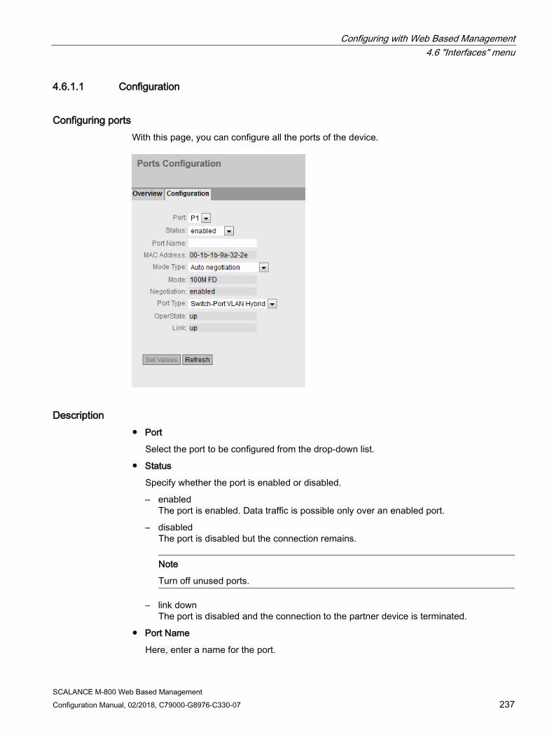
Configuring with Web Based Management 4.6 "Interfaces" menu
SCALANCE M-800 Web Based Management Configuration Manual, 02/2018, C79000-G8976-C330-07 237
4.6.1.1 Configuration
Configuring ports With this page, you can configure all the ports of the device.
Description ● Port
Select the port to be configured from the drop-down list.
● Status
Specify whether the port is enabled or disabled.
– enabled The port is enabled. Data traffic is possible only over an enabled port.
– disabled The port is disabled but the connection remains.
Note
Turn off unused ports.
– link down The port is disabled and the connection to the partner device is terminated.
● Port Name
Here, enter a name for the port.

Configuring with Web Based Management 4.6 "Interfaces" menu
SCALANCE M-800 Web Based Management 238 Configuration Manual, 02/2018, C79000-G8976-C330-07
● MAC Address
Shows the MAC address of the port.
● Mode Type
From this drop-down list, select the transmission speed and the transfer mode of the port.
The following settings are possible:
– 10 Mbps full duplex (FD) or half duplex (HD)
– 100 Mbps full duplex (FD) or half duplex (HD)
– Auto negotiation
If you set the mode to "Auto negotiation", these parameters are automatically negotiated with the connected end device or network component. This must also be in the "Autonegotiation" mode.
Note
Before the port and partner port can communicate with each other, the settings must match at both ends.
● Mode
Shows the transmission speed and the transmission mode of the port. The display depends on the set "Mode Type".
● Negotiation
Shows whether the automatic configuration of the connection to the partner port is enabled or disabled.
● Port Type
Select the type of port from the drop-down list.
– Switch Port VLAN Hybrid
The port sends tagged and untagged frames. It is not automatically a member of a VLAN.
– Switch-Port VLAN Trunk
The port only sends tagged frames and is automatically a member of all VLANs.
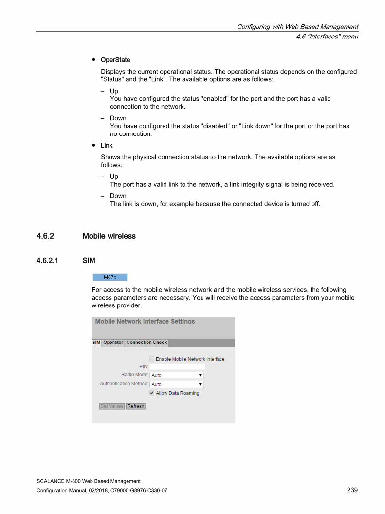
Configuring with Web Based Management 4.6 "Interfaces" menu
SCALANCE M-800 Web Based Management Configuration Manual, 02/2018, C79000-G8976-C330-07 239
● OperState
Displays the current operational status. The operational status depends on the configured "Status" and the "Link". The available options are as follows:
– Up You have configured the status "enabled" for the port and the port has a valid connection to the network.
– Down You have configured the status "disabled" or "Link down" for the port or the port has no connection.
● Link
Shows the physical connection status to the network. The available options are as follows:
– Up The port has a valid link to the network, a link integrity signal is being received.
– Down The link is down, for example because the connected device is turned off.
4.6.2 Mobile wireless
4.6.2.1 SIM
For access to the mobile wireless network and the mobile wireless services, the following access parameters are necessary. You will receive the access parameters from your mobile wireless provider.

Configuring with Web Based Management 4.6 "Interfaces" menu
SCALANCE M-800 Web Based Management 240 Configuration Manual, 02/2018, C79000-G8976-C330-07
Description The page contains the following:
● Enable Mobile Network Interface
Enable or disable the mobile wireless interface.
● PIN Enter the PIN of the SIM card. You obtain the PIN from your mobile wireless provider. The device also works with SIM cards without a PIN, in this case leave the box empty.
Note
If you make incorrect entries, the SIM card is blocked
Make sure that you enter the PIN correctly. If you enter the PIN incorrectly more than three times, the SIM card will be blocked.
In "Information > Mobile", you can check the status of the SIM card. If "SIM Status" displays "PUK required", the SIM card is blocked.
To release it, the card needs to be taken out of the device and inserted in a mobile wireless telephone. By entering the PUK, the SIM card can be released again. If necessary, contact your mobile wireless provider.
● Radio Mode
Select the required mobile wireless network. The following options are available:
– Auto (not with M874-2) All services. As first choice, the device attempts to establish a connection to the fastest available mobile wireless system.
– GSM only The EGPRS and GPRS services. The device ignores the UMTS and LTE network and establishes a connection to the GSM service that provides the highest bandwidth locally
– UMTS only (not with M874-2) The UMTS and HSPA service. The device ignores the EGPRS, GPRS and LTE services and establishes a connection in the UMTS network.
– LTE only (available only with the M876-4) The LTE service. The device ignores the EGPRS and GPRS and UMTS services and establishes a connection in the LTE network.
– No data connection There is no data connection. The mode is suitable for the situation when the device only wants to send or receive SMS messages.

Configuring with Web Based Management 4.6 "Interfaces" menu
SCALANCE M-800 Web Based Management Configuration Manual, 02/2018, C79000-G8976-C330-07 241
● Authentication Method
Select the required authentication method.
– CHAP Encrypted transfer of user name and password using the Challenge Handshake Authentication Protocol (CHAP).
– PAP Unencrypted transfer of user name and password using the Password Authentication Protocol (PAP).
– Auto User name and password are transferred automatically with one of the following two methods. CHAP has the higher priority. If the communications partner does not support CHAP, the user name and password are transferred using PAP.
● Allow Data Roaming
When enabled, the device automatically logs in to an available network if the specified network is unreachable.
4.6.2.2 Mobile wireless provider
The APN (Access Point Name) is the name of the access point from the mobile wireless network to the Internet or to a private company network. Depending on the type of network connected, this is a public or private APN. Information about the APN is provided by the mobile wireless provider.

Configuring with Web Based Management 4.6 "Interfaces" menu
SCALANCE M-800 Web Based Management 242 Configuration Manual, 02/2018, C79000-G8976-C330-07
Description The page contains the following:
● Country List
From this list, select the country in which the device will be deployed.
● Provider List
From this list select the appropriate mobile wireless provider. The list depends on the selected country.
If the mobile wireless provider is not contained in the list of providers, select "-".
● PLMNID
Each mobile wireless provider has an identification number that is unique worldwide known as the Public Land Mobile Network ID (PLMN ID). You will find the Net ID in the documentation of your mobile wireless provider or on their Internet pages.
– If you know the identification number (Net ID) of the network provider, enter it.
– If you do not know the PLMNID enter "Manual".
● APN
Enter the name of the APN. You will find the APN in the documentation of your mobile wireless provider on your provider's Website or ask your mobile wireless provider's hotline.
● User Name
Enter the user name. Some mobile wireless providers do not use access control with user names and/or passwords. In this case, leave the box empty.
● Password
Enter the password. Some mobile wireless providers do not use access control with user names and/or passwords. In this case, leave the box empty.
● Password Confirmation
Repeat the password.
This table contains the following columns:
● Select
Select the check box in the row to be deleted.
● PLMNID
Shows the identification number (Net ID) of the mobile wireless provider.
● Operator Name
Enter the name of your mobile wireless provider.
● APN
Enter the name of the APN. You will find the APN in the documentation of your mobile wireless provider on your provider's Website or ask your mobile wireless provider's hotline.
Configuring with Web Based Management 4.6 "Interfaces" menu
SCALANCE M-800 Web Based Management Configuration Manual, 02/2018, C79000-G8976-C330-07 243
● User Name
Enter the user name for the APN. Some mobile wireless providers do not use access control with user names and/or passwords. In this case, leave the box empty.
● Password
Enter the password for the APN. Some mobile wireless providers do not use access control with user names and/or passwords. In this case, leave the box empty.
● Password Confirmation
Repeat the password.
● Enabled
The entry is used
4.6.2.3 Connection Check
Use this function to ensure that the connection to the mobile wireless network is retained. On this page you specify which WAN-IP addresses are used as reference for the connection monitoring.
The device sends echo messages (pings) to the configured WAN IP addresses of the remote stations at regular intervals (Ping Time Interval).
If, for example, you configure three WAN-IP addresses, the device sends a ping to the first WAN-IP address. If this WAN-IP address is reachable, it sends a reply. When the configured interval has elapsed, the device sends the next ping. If the first WAN-IP address cannot be reached, the device sends a further ping after a waiting time has elapsed (10 s). In total three pings are sent to the WAN-IP address. If the device does not receive a reply after the third ping, the second WAN-IP address is checked. If this WAN-IP addresses is also unreachable, the next WAN-IP address is checked.
Is none of the three WAN-IP addresses is reachable, the device restarts the mobile wireless interface and logs the restart with the following message "Detected a problem with the provider connection. Trying to reconnect to the provider. Attempt no.: x".
The x stands for the number of attempts. In total the device makes 10 attempts. After restarting the mobile wireless interface, the device waits for some time and then sends a ping to the first WAN-IP address. Following the first restart of the mobile wireless interface the wait time is 2 minutes. With each further restart of the mobile wireless interface the wait time is extended by one minute.
If the 10 attempts are unsuccessful, the device restarts and logs the restart with the following message: "Detected a problem with the provider connection. Reconnect to the provider had no effect. Device will restart now."
Note
Always configure several WAN-IP addresses. If you only configure one WAN-IP address, the sporadic failure of the single WAN-IP address can lead to the WAN connection being constantly re-established.

Configuring with Web Based Management 4.6 "Interfaces" menu
SCALANCE M-800 Web Based Management 244 Configuration Manual, 02/2018, C79000-G8976-C330-07
Description The page contains the following:
● Enable Connection Ping
Enable or disable the function. Can only be enabled if at least one IP address is configured.
● Ping Time Interval [s]
Specify the interval at which the pings are sent.
● Ping Target Address
Enter the WAN-IP address that will be used for the connection monitoring.. Click "Create" to save an entry to the table
This table contains the following columns:
● Select
Select the check box in the row to be deleted.
● Target Address
Shows the WAN-IP address.
4.6.3 DSL
On this WBM page, you configure the DSL access and the parameters for the virtual connection via which the packets will be transferred.

Configuring with Web Based Management 4.6 "Interfaces" menu
SCALANCE M-800 Web Based Management Configuration Manual, 02/2018, C79000-G8976-C330-07 245
Description The page contains the following:
● Enable DSL Interface
Enable or disable the DSL interface.
● Enable PPPoE Passthrough
– Enabled
The device acts as a modem. The settings "Account", "Password" and "Enable Force Disconnect" cannot be edited. Only a connected device can use the DSL connection. This device also handles the authentication (dial-in) with the provider.
– Disabled
The device acts as a router and logs in with the user name and password. All connected devices can use the DSL connection.
● User Account
Enter the user name. You will receive the user name from your DSL provider.
● Password
Enter the password. You will receive the password name from your DSL provider.
● Password Confirmation
Repeat the password.
Configuring with Web Based Management 4.6 "Interfaces" menu
SCALANCE M-800 Web Based Management 246 Configuration Manual, 02/2018, C79000-G8976-C330-07
● VCI (Virtual Channel Identifier)
Enter the ID for the virtual channel. You will receive setting from your DSL provider.
● VPI (Virtual Path Identifier)
Enter the ID for the virtual path. You will receive setting from your DSL provider.
● Encapsulation
The data packets are encapsulated in the required protocol.
The following options are available:
– vc-mux (virtual circuit multiplexing)
– LLC (Logical Link Control)
● Protocol
Specify the protocol for the Internet connection. You obtain this information from your DSL provider.
– PPPoE (Point-to-Point over Ethernet)
The PPP data is encapsulated in an Ethernet frame.
– PPPoA (Point-to-Point over ATM)
The PPP data is encapsulated in ATM AAL5 (Adaptation Layer 5). If you select PPPoA, the setting "Enable PPPoE Passthrough" is disabled.
● Noise Margin Delta DS
Specify the margin to the background noise.
Range of values -5dB ... +5dB
● Enable Vlan ID
When enabled, you can configure a VLAN ID. Only necessary when specification of a VLAN ID is required for the DSL access.
● VLAN ID
Enter the VLAN ID for the DSL access. You will receive setting from your DSL provider.
● Forced Disconnect
After a certain time, the DSL provider terminates the connection. Enable this option if you want to shift the forced disconnect of your provider to a specific time of day, for example at night outside normal office hours.
● Time for Forced Disconnect
Specify the time of day to which you want to shift the forced disconnect of the DSL provider. This is only possible if the correct system time is set on the device. Input format: HH:MM

Configuring with Web Based Management 4.6 "Interfaces" menu
SCALANCE M-800 Web Based Management Configuration Manual, 02/2018, C79000-G8976-C330-07 247
4.6.4 SHDSL
4.6.4.1 Overview
The WBM page shows the configuration of the SHDSL interfaces.
Description The page contains the following:
● Enable PME Aggregation Function
PME = Physical Medium Entities
When enabled, the SHDSL interfaces or the 2-wire cables are put together to form a single connection with a higher transmission rate.
Note
If the "PME Aggregation" function is enabled, the interfaces of a device must each have the same role.
This table contains the following columns:
● Interface
Shows the available SHDSL interfaces.
● Status
Shows whether or not the interface is used.

Configuring with Web Based Management 4.6 "Interfaces" menu
SCALANCE M-800 Web Based Management 248 Configuration Manual, 02/2018, C79000-G8976-C330-07
● Role
Shows the role of the SHDSL interface:
– Central Office (CO) The interface is a central office.
– Customer Premises Equipment (CPE) The interface is an end node device.
● Target SNR
Shows the signal-to-noise ratio:
– Reliability (10 dB) Reliable transfer
– Normal (6 dB) Normal transfer
– High-speed (0 dB) High-speed transfer
● Port Type
Shows the operating mode of the switch port:
– Switch-Port VLAN Hybrid
The port accepts tagged and untagged frames.
– Switch-Port VLAN Trunk
The port only sends tagged frames and is automatically a member of all VLANs.
4.6.4.2 Configuration
On this WBM page, you specify the settings for the connection and the role of the device. You will find further information on the settings in ITU-T G.991.2.

Configuring with Web Based Management 4.6 "Interfaces" menu
SCALANCE M-800 Web Based Management Configuration Manual, 02/2018, C79000-G8976-C330-07 249
Description The page contains the following:
● Interface
Select the interface.
● Status
Specify whether or not the interface will be used.
● Port Type
Specify the operating mode for the switch port.
– Switch-Port VLAN Hybrid
The port accepts tagged and untagged frames.
– Switch-Port VLAN Trunk
The port only sends tagged frames and is automatically a member of all VLANs.
Configuring with Web Based Management 4.6 "Interfaces" menu
SCALANCE M-800 Web Based Management 250 Configuration Manual, 02/2018, C79000-G8976-C330-07
● Role Specify the role:
– Central Office (CO)
The interface is a central office.
– Customer Premises Equipment (CPE)
The interface is an end node device.
● Predefined Profile
Specify the profile for the transfer. If you use a profile, the following parameters are set automatically.
– Profiles with a transfer range
If during calibration of the cable the measured value is within the range, the SHDSL connection is established.
Link data rate min - max
Standard 192 - 5696 For medium and longer cable lengths Reliability 192 - 5696 When operating several SHDSL connections simultaneously. Extended 64 - 15296 For short and long cable length
– Profiles with a fixed preset transmission rate
If during calibration of the cable the measured value precisely matches the fixed preset transmission rate, and SHDSL connection is established.
Link Data Rate Fixed (High Rate) 5696 Fixed (Medium Rate) 3072 Fixed (Low Rate) 512
● Extended Mode
Enable or disable the extended mode. Depending on the setting, the selection in the following boxes changes.
● PAM
Pulse Amplitude Modulation
Specify the modulation method.
● Line probing
When enabled, the cable is calibrated according to ITU-T G.991.2.
Configuring with Web Based Management 4.6 "Interfaces" menu
SCALANCE M-800 Web Based Management Configuration Manual, 02/2018, C79000-G8976-C330-07 251
● SNR Model
Specify the model for calculating the signal-to-noise ratio.
– Current Condition
The value for noise is used that was measured when calibrating the cable.
– Worst Case
The value for noise is assumed that could occur over several cables of a cable bundle.
● Target SNR
Specify the transmission mode for the signal-to-noise ratio. The current signal-to-noise ratio is displayed under "Information > SHDSL".
– Reliability (10 dB) Reliable transfer
– Normal (6 dB) Normal transfer
– High-speed (0 dB) High-speed transfer
● Min. Link Data Rate [kbps] Specify the minimum transmission rate for sending and receiving data.
– Auto (0) The device adapts the transmission rate automatically depending on the mode.
– 64 to 15296 The transmission rate is specified as a fixed value.
● Max. Link Data Rate [kbps] Specify the maximum transmission rate for sending and receiving data.
– Auto (0) The device adapts the transmission rate automatically depending on the mode.
– 64 to 15296 The transmission rate is specified as a fixed value.
Configuring with Web Based Management 4.6 "Interfaces" menu
SCALANCE M-800 Web Based Management 252 Configuration Manual, 02/2018, C79000-G8976-C330-07
● Power Regulation Specify whether or not the transmit power is reduced.
– Disabled
The function is disabled
– Normal
The function is enabled.
– Force
For PBO Value, enter the value for the attenuation.
● PBO Value
Power Back Off Values Enter the value for the attenuation. An SHDSL connection is only established when the value is reached.
– Range: 0 - 31 dB, where "0" means no attenuation.
4.6.4.3 Connection Check
Use this function to ensure that the connection to the SHDSL network is retained. On this page you specify which WAN-IP addresses are used as reference for the connection monitoring.
The device sends echo messages (pings) to the configured WAN IP addresses of the remote stations at regular intervals (Ping Time Interval).
If, for example, you configure three WAN-IP addresses, the device sends a ping to the WAN-IP addresses. If only one of the three WAN-IP addresses is unreachable the following message is logged: "Could not reach remote device a.b.c.d (Failure count x)".
"a.b.c.d" stands for the IP address of the device and x stands for the number of attempts. In total the device makes 5 attempts.
If the IP address becomes reachable again, this is logged with the following message: SHDSL connection check: Remote devices are reachable again.
If the 5 attempts are unsuccessful, the device restarts and logs the restart with the following message: "SHDSL connection check: Maximum failure count reached, restarting device."
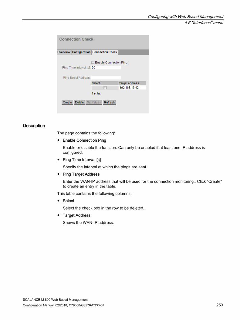
Configuring with Web Based Management 4.6 "Interfaces" menu
SCALANCE M-800 Web Based Management Configuration Manual, 02/2018, C79000-G8976-C330-07 253
Description The page contains the following:
● Enable Connection Ping
Enable or disable the function. Can only be enabled if at least one IP address is configured.
● Ping Time Interval [s]
Specify the interval at which the pings are sent.
● Ping Target Address
Enter the WAN-IP address that will be used for the connection monitoring.. Click "Create" to create an entry in the table.
This table contains the following columns:
● Select
Select the check box in the row to be deleted.
● Target Address
Shows the WAN-IP address.

Configuring with Web Based Management 4.7 "Layer 2" menu
SCALANCE M-800 Web Based Management 254 Configuration Manual, 02/2018, C79000-G8976-C330-07
4.7 "Layer 2" menu
4.7.1 Layer 2 configuration
Configuring layer 2 On this page, you create a basic configuration for the functions of layer 2.
Description ● Passive Listening
When enabled the function ensures that the BPDUs from the RSTP network are forwarded transparently and return again. If this was not the case, loops would form at the connection point between RSTP and the ring.
4.7.2 VLAN
4.7.2.1 General
VLAN configuration page On this page you specify whether or not the device forwards frames with VLAN tags transparently (IEEE 802.1D/VLAN-unaware mode) or takes VLAN information into account (IEEE 802.1Q/VLAN-aware mode). If the device is in the "802.1Q VLAN Bridge" mode, you can define VLANs and specify the use of the ports.
The possible settings on this page depend on what you select in the "Base Bridge Mode" box.
Note Changing the Agent VLAN ID
If the configuration PC is connected directly to the device via Ethernet and you change the agent VLAN ID, the device is no longer reachable via Ethernet following the change.
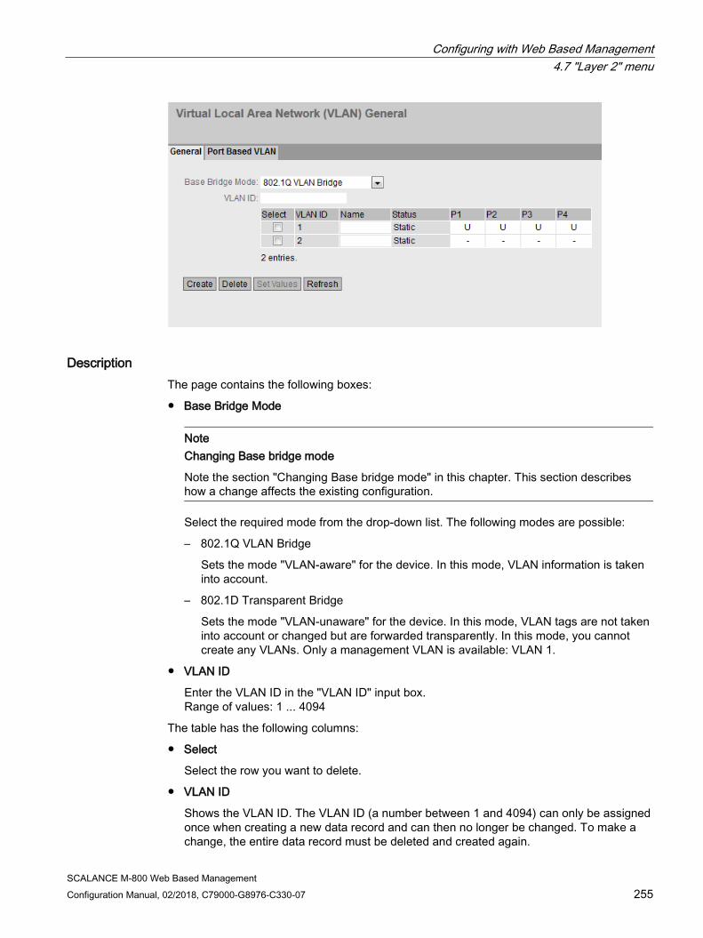
Configuring with Web Based Management 4.7 "Layer 2" menu
SCALANCE M-800 Web Based Management Configuration Manual, 02/2018, C79000-G8976-C330-07 255
Description The page contains the following boxes:
● Base Bridge Mode
Note
Changing Base bridge mode
Note the section "Changing Base bridge mode" in this chapter. This section describes how a change affects the existing configuration.
Select the required mode from the drop-down list. The following modes are possible:
– 802.1Q VLAN Bridge
Sets the mode "VLAN-aware" for the device. In this mode, VLAN information is taken into account.
– 802.1D Transparent Bridge
Sets the mode "VLAN-unaware" for the device. In this mode, VLAN tags are not taken into account or changed but are forwarded transparently. In this mode, you cannot create any VLANs. Only a management VLAN is available: VLAN 1.
● VLAN ID
Enter the VLAN ID in the "VLAN ID" input box. Range of values: 1 ... 4094
The table has the following columns:
● Select
Select the row you want to delete.
● VLAN ID
Shows the VLAN ID. The VLAN ID (a number between 1 and 4094) can only be assigned once when creating a new data record and can then no longer be changed. To make a change, the entire data record must be deleted and created again.
Configuring with Web Based Management 4.7 "Layer 2" menu
SCALANCE M-800 Web Based Management 256 Configuration Manual, 02/2018, C79000-G8976-C330-07
● Name Enter a name for the VLAN. The name only provides information and has no effect on the configuration. The length is a maximum of 32 characters.
● Status Shows the status type of the entry in the internal port filter table. Here, "Static" means that the VLAN was entered statically by the user.
● List of ports Specify the use of the port. The following options are available:
– "-" The port is not a member of the specified VLAN. With a new definition, all ports have the identifier "-".
– M The port is a member of the VLAN. Frames sent in this VLAN are forwarded with the corresponding VLAN tag.
– U (uppercase) The port is an untagged member of the VLAN. Frames sent in this VLAN are forwarded without the VLAN tag. Frames without a VLAN tag are sent from this port.
– u (lowercase) The port is an untagged member of the VLAN, but the VLAN is not configured as a port VLAN. Frames sent in this VLAN are forwarded without the VLAN tag.
– F The port is not a member of the specified VLAN and cannot become a member of this VLAN even if it is configured as a trunk port.
– T This option is only displayed and cannot be selected in the WBM. This port is a trunk port making it a member in all VLANs. You configure this function in the CLI (Command Line Interface) using the "switchport mode trunk" command or in the WBM under "Interfaces > Ethernet > Configuration".
Changing Base bridge mode VLAN-unaware (802.1D transparent bridge) → VLAN-aware (802.1Q VLAN bridge)
If you change the Base bridge mode from VLAN-unaware to VLAN aware, this has the following effects
● All static and dynamic unicast entries are deleted.

Configuring with Web Based Management 4.7 "Layer 2" menu
SCALANCE M-800 Web Based Management Configuration Manual, 02/2018, C79000-G8976-C330-07 257
VLAN-aware (802.1Q VLAN bridge) → VLAN-unaware (802.1D transparent bridge)
If you change the Base bridge mode from VLAN-aware to VLAN-unaware, this has the following effects
● All VLAN configurations are deleted.
● A management VLAN is created: VLAN 1.
● All static and dynamic unicast entries are deleted.
802.1Q VLAN Bridge: Important rules for VLANs Make sure you keep to the following rules when configuring and operating your VLANs:
● Frames with the VLAN ID "0" are handled as untagged frames but retain their priority value.
● As default, all ports on the device send frames without a VLAN tag to ensure that the end node can receive these frames.
● You will find the factory assignment of the ports in the section "VLAN (Page 39)".
● The VLANs are in different IP subnets. To allow these to communicate with each other, the route and firewall rule must be configured on the device.
● If an end node is connected to a port, outgoing frames should be sent without a tag (static access port). If, however, there is a further switch at this port, the frame should have a tag added (trunk port).
Procedure Requirement:
For Base Bridge mode "802.1Q VLAN Bridge" is set
Creating a new VLAN
1. Enter an ID in the "VLAN ID" input box.
2. Click the "Create" button. A new entry is generated in the table. As default, the boxes have "-" entered.
3. Enter a name for the VLAN under Name.
4. Specify the use of the port in the VLAN. If, for example you select M, the port is a member of the VLAN. The frame sent in this VLAN is forwarded with the corresponding VLAN tag.
5. Specify the mode of the device.
6. Click the "Set Values" button.
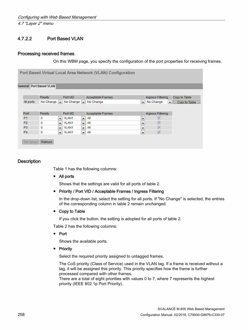
Configuring with Web Based Management 4.7 "Layer 2" menu
SCALANCE M-800 Web Based Management 258 Configuration Manual, 02/2018, C79000-G8976-C330-07
4.7.2.2 Port Based VLAN
Processing received frames On this WBM page, you specify the configuration of the port properties for receiving frames.
Description Table 1 has the following columns:
● All ports
Shows that the settings are valid for all ports of table 2.
● Priority / Port VID / Acceptable Frames / Ingress Filtering
In the drop-down list, select the setting for all ports. If "No Change" is selected, the entries of the corresponding column in table 2 remain unchanged.
● Copy to Table
If you click the button, the setting is adopted for all ports of table 2.
Table 2 has the following columns:
● Port
Shows the available ports.
● Priority
Select the required priority assigned to untagged frames.
The CoS priority (Class of Service) used in the VLAN tag. If a frame is received without a tag, it will be assigned this priority. This priority specifies how the frame is further processed compared with other frames. There are a total of eight priorities with values 0 to 7, where 7 represents the highest priority (IEEE 802.1p Port Priority).

Configuring with Web Based Management 4.7 "Layer 2" menu
SCALANCE M-800 Web Based Management Configuration Manual, 02/2018, C79000-G8976-C330-07 259
● Port VID Select the required VLAN ID. Only VLAN IDs defined in "VLAN > General" can be selected. If a received frame does not have a VLAN tag, it has a tag with the VLAN ID specified here added to it and is sent according to the rules at the port.
● Acceptable Frames
Specify which types of frames will be accepted. The following alternatives are possible:
– Tagged Frames Only The device discards all untagged frames. Otherwise, the forwarding rules apply according to the configuration.
– All The device forwards all frames.
● Ingress Filtering
Specify whether the VID of received frames is evaluated. You have the following options:
– Enabled The VLAN ID of received frames decides whether they are forwarded: To forward a VLAN tagged frame, the receiving port must be a member in the same VLAN. Frames from unknown VLANs are discarded at the receiving port.
– Disabled All frames are forwarded.
Steps in configuration 1. In the row of the port to be configured, click on the relevant cell in the table to configure it.
2. Enter the values to be set in the input boxes as follows.
3. Select the values to be set from the drop-down lists.
4. Click the "Set Values" button.
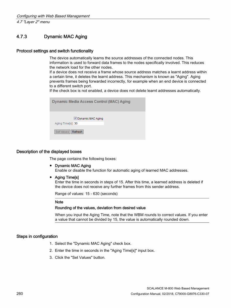
Configuring with Web Based Management 4.7 "Layer 2" menu
SCALANCE M-800 Web Based Management 260 Configuration Manual, 02/2018, C79000-G8976-C330-07
4.7.3 Dynamic MAC Aging
Protocol settings and switch functionality The device automatically learns the source addresses of the connected nodes. This information is used to forward data frames to the nodes specifically involved. This reduces the network load for the other nodes. If a device does not receive a frame whose source address matches a learnt address within a certain time, it deletes the learnt address. This mechanism is known as "Aging". Aging prevents frames being forwarded incorrectly, for example when an end device is connected to a different switch port. If the check box is not enabled, a device does not delete learnt addresses automatically.
Description of the displayed boxes The page contains the following boxes:
● Dynamic MAC Aging Enable or disable the function for automatic aging of learned MAC addresses.
● Aging Time[s] Enter the time in seconds in steps of 15. After this time, a learned address is deleted if the device does not receive any further frames from this sender address.
Range of values: 15 - 630 (seconds)
Note Rounding of the values, deviation from desired value
When you input the Aging Time, note that the WBM rounds to correct values. If you enter a value that cannot be divided by 15, the value is automatically rounded down.
Steps in configuration 1. Select the "Dynamic MAC Aging" check box.
2. Enter the time in seconds in the "Aging Time[s]" input box.
3. Click the "Set Values" button.
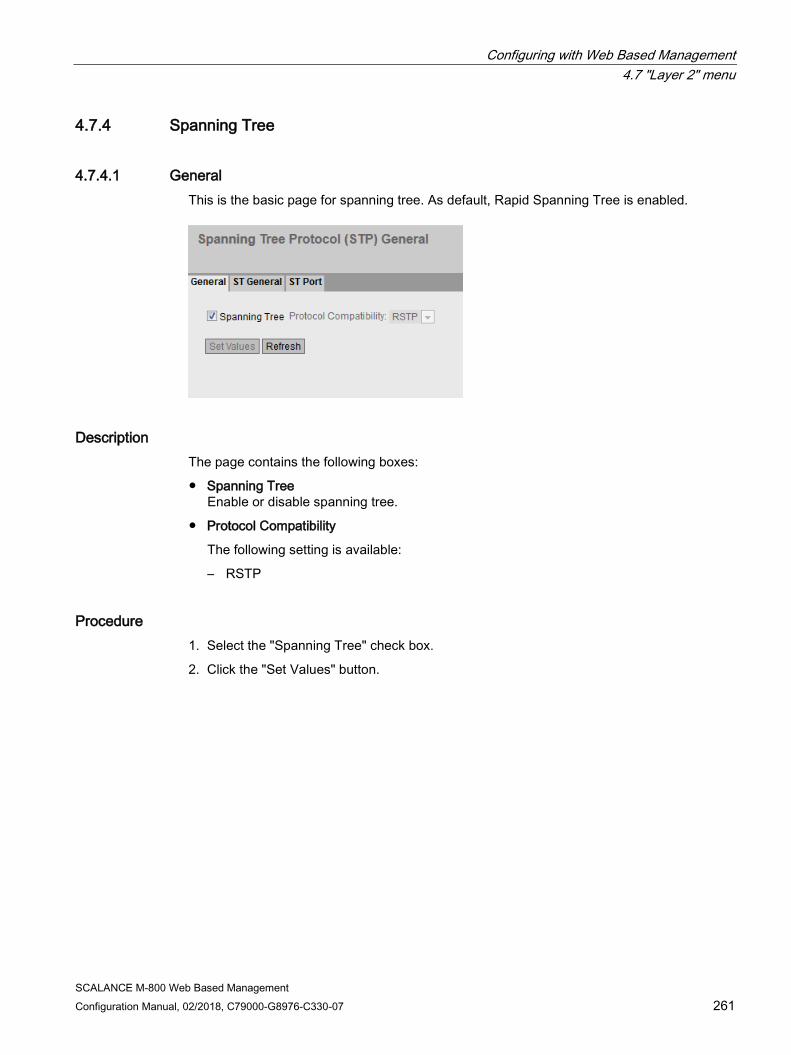
Configuring with Web Based Management 4.7 "Layer 2" menu
SCALANCE M-800 Web Based Management Configuration Manual, 02/2018, C79000-G8976-C330-07 261
4.7.4 Spanning Tree
4.7.4.1 General This is the basic page for spanning tree. As default, Rapid Spanning Tree is enabled.
Description The page contains the following boxes:
● Spanning Tree Enable or disable spanning tree.
● Protocol Compatibility
The following setting is available:
– RSTP
Procedure 1. Select the "Spanning Tree" check box.
2. Click the "Set Values" button.
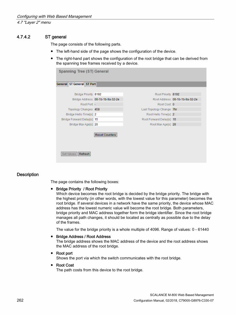
Configuring with Web Based Management 4.7 "Layer 2" menu
SCALANCE M-800 Web Based Management 262 Configuration Manual, 02/2018, C79000-G8976-C330-07
4.7.4.2 ST general The page consists of the following parts.
● The left-hand side of the page shows the configuration of the device.
● The right-hand part shows the configuration of the root bridge that can be derived from the spanning tree frames received by a device.
Description The page contains the following boxes:
● Bridge Priority / Root Priority Which device becomes the root bridge is decided by the bridge priority. The bridge with the highest priority (in other words, with the lowest value for this parameter) becomes the root bridge. If several devices in a network have the same priority, the device whose MAC address has the lowest numeric value will become the root bridge. Both parameters, bridge priority and MAC address together form the bridge identifier. Since the root bridge manages all path changes, it should be located as centrally as possible due to the delay of the frames.
The value for the bridge priority is a whole multiple of 4096. Range of values: 0 - 61440
● Bridge Address / Root Address The bridge address shows the MAC address of the device and the root address shows the MAC address of the root bridge.
● Root port Shows the port via which the switch communicates with the root bridge.
● Root Cost The path costs from this device to the root bridge.
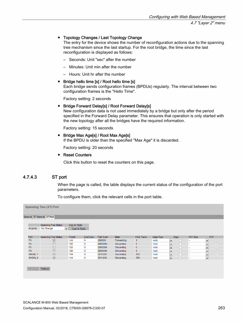
Configuring with Web Based Management 4.7 "Layer 2" menu
SCALANCE M-800 Web Based Management Configuration Manual, 02/2018, C79000-G8976-C330-07 263
● Topology Changes / Last Topology Change The entry for the device shows the number of reconfiguration actions due to the spanning tree mechanism since the last startup. For the root bridge, the time since the last reconfiguration is displayed as follows:
– Seconds: Unit "sec" after the number
– Minutes: Unit min after the number
– Hours: Unit hr after the number
● Bridge hello time [s] / Root hello time [s] Each bridge sends configuration frames (BPDUs) regularly. The interval between two configuration frames is the "Hello Time".
Factory setting: 2 seconds
● Bridge Forward Delay[s] / Root Forward Delay[s] New configuration data is not used immediately by a bridge but only after the period specified in the Forward Delay parameter. This ensures that operation is only started with the new topology after all the bridges have the required information.
Factory setting: 15 seconds
● Bridge Max Age[s] / Root Max Age[s] If the BPDU is older than the specified "Max Age" it is discarded.
Factory setting: 20 seconds
● Reset Counters
Click this button to reset the counters on this page.
4.7.4.3 ST port When the page is called, the table displays the current status of the configuration of the port parameters.
To configure them, click the relevant cells in the port table.
Configuring with Web Based Management 4.7 "Layer 2" menu
SCALANCE M-800 Web Based Management 264 Configuration Manual, 02/2018, C79000-G8976-C330-07
Description Table 1 has the following columns:
● All ports
Shows that the settings are valid for all ports of table 2.
● Spanning Tree Status
In the drop-down list, select the setting for all ports. If "No Change" is selected, the entries of the corresponding column in table 2 remain unchanged.
● Copy to Table
If you click the button, the setting is adopted for all ports of table 2.
Table 2 has the following columns:
● Port Shows the available ports.
● Spanning Tree Status Specify whether or not the port is integrated in the spanning tree.
Note
If you disable the "Spanning Tree Status" option for a port, this may cause the formation of loops. The topology must be kept in mind.
● Priority Enter the priority of the port. The priority is only evaluated when the path costs are the same. The value must be divisible by 16. If the value that cannot be divided by 16, the value is automatically adapted. Range of values: 0 - 240. The default is 128.
● Cost Calc. Enter the path cost calculation. If you enter the value "0" here, the automatically calculated value is displayed in the "Path costs" box.

Configuring with Web Based Management 4.7 "Layer 2" menu
SCALANCE M-800 Web Based Management Configuration Manual, 02/2018, C79000-G8976-C330-07 265
● Path Cost This parameter is used to calculate the path that will be selected. The path with the lowest value is selected as the path. If several ports of a device have the same value for the path costs, the port with the lowest port number is selected. If the value in the Cost Calc." is "0", the automatically calculated value is shown. Otherwise, the value of the "Cost Calc." box is displayed. The calculation of the path costs is largely based on the transmission speed. The higher the achievable transmission speed is, the lower the value of the path costs.
Typical values for path costs with rapid spanning tree:
– 10,000 Mbps = 2,000
– 1000 Mbps = 20,000
– 100 Mbps = 200,000
– 10 Mbps = 2,000,000
The values can, however, also be set individually.
● Status Displays the current status of the port. The values are only displayed and cannot be configured. The "Status" parameter depends on the configured protocol. The following values are possible:
– Disabled The port only receives and is not involved in STP, MSTP and RSTP.
– Discarding In the "Discarding" mode, BPDU frames are received. Other incoming or outgoing frames are discarded.
– Listening In this status, BPDUs are both received and sent. The port is involved in the spanning tree algorithm.
– Learning Stage prior to the "Forwarding" status, the port is actively learning the topology (in other words, the node addresses).
– Forwarding Following the reconfiguration time, the port is active in the network; it receives and forwards data frames.
● Fwd. Trans Specifies the number of changes from the "Discarding" status to the "Forwarding" status.
● Edge Type Specify the type of "edge port". You have the following options:
– "-" Edge port is disabled. The port is treated as a "no Edge Port".
– Admin Select this option when there is always an end device on this port. Otherwise a reconfiguration of the network will be triggered each time a connection is changed.
Configuring with Web Based Management 4.7 "Layer 2" menu
SCALANCE M-800 Web Based Management 266 Configuration Manual, 02/2018, C79000-G8976-C330-07
– Auto Select this option if you want a connected end device to be detected automatically at this port. When the connection is established the first time, the port is treated as a "no Edge Port".
– Admin/Auto Select these options if you operate a combination of both on this port. When the connection is established the first time, the port is treated as an "Edge Port".
● Edge Shows the status of the port.
– Enabled An end device is connected to this port.
– Disabled There is a Spanning Tree or Rapid Spanning Tree device at this port.
With an end device, a switch can change over the port faster without taking into account spanning tree frames. If a spanning tree frame is received despite this setting, the port automatically changes to the "Disabled" setting.
● P.t.P. Type Select the required option from the drop-down list. The selection depends on the port that is set.
– "-" Point to point is calculated automatically. If the port is set to half duplex, a point-to-point link is not assumed.
– P.t.P. Even with half duplex, a point-to-point link is assumed.
– Shared Media Even with a full duplex connection, a point-to-point link is not assumed.
Note
Point-to-point connection means a direct connection between two devices. A shared media connection is, for example, a connection to a hub.
● Hello Time Enter the interval after which the bridge sends configuration frames (BPDUs). As default, 2 seconds is set. Range of values: 1-2 seconds
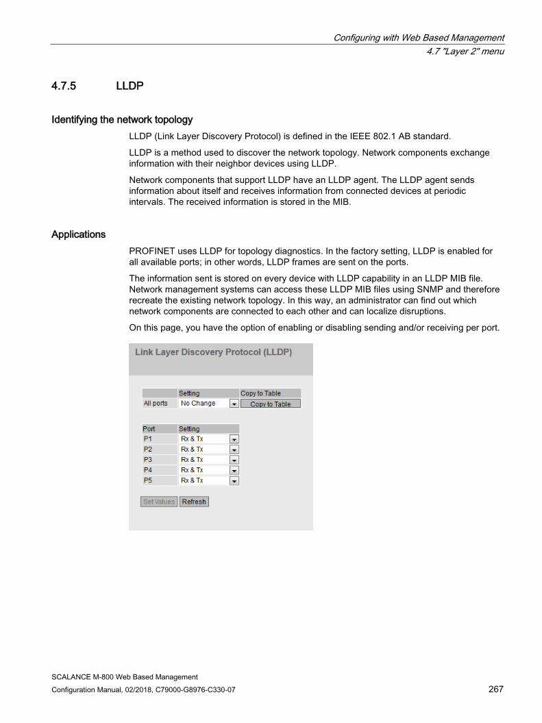
Configuring with Web Based Management 4.7 "Layer 2" menu
SCALANCE M-800 Web Based Management Configuration Manual, 02/2018, C79000-G8976-C330-07 267
4.7.5 LLDP
Identifying the network topology LLDP (Link Layer Discovery Protocol) is defined in the IEEE 802.1 AB standard.
LLDP is a method used to discover the network topology. Network components exchange information with their neighbor devices using LLDP.
Network components that support LLDP have an LLDP agent. The LLDP agent sends information about itself and receives information from connected devices at periodic intervals. The received information is stored in the MIB.
Applications PROFINET uses LLDP for topology diagnostics. In the factory setting, LLDP is enabled for all available ports; in other words, LLDP frames are sent on the ports.
The information sent is stored on every device with LLDP capability in an LLDP MIB file. Network management systems can access these LLDP MIB files using SNMP and therefore recreate the existing network topology. In this way, an administrator can find out which network components are connected to each other and can localize disruptions.
On this page, you have the option of enabling or disabling sending and/or receiving per port.

Configuring with Web Based Management 4.7 "Layer 2" menu
SCALANCE M-800 Web Based Management 268 Configuration Manual, 02/2018, C79000-G8976-C330-07
Description Table 1 has the following columns:
● All Ports Shows that the settings are valid for all ports.
● Setting Select the setting from the drop-down list. If "No Change" is selected, the entry in table 2 remains unchanged.
● Copy to Table If you click the button, the setting is adopted for all ports of table 2.
Table 2 has the following columns:
● Port Shows the available ports.
● Setting Specify the LLDP functionality. The following options are available:
– Rx This port can only receive LLDP frames.
– Tx This port can only send LLDP frames.
– Rx & Tx This port can receive and send LLDP frames.
– "-" (disabled) This port can neither receive nor send LLDP frames.
Procedure 1. Select the LLDP functionality of the port from the "Setting" drop-down list.
2. Click the "Set Values" button.
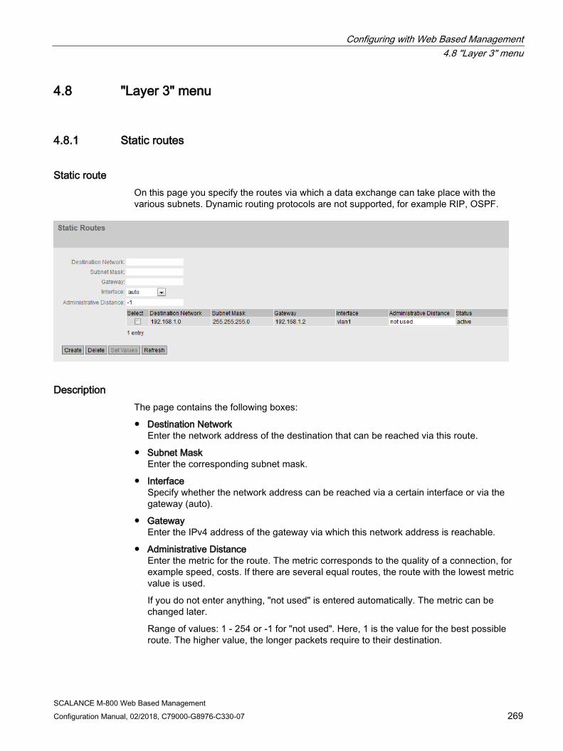
Configuring with Web Based Management 4.8 "Layer 3" menu
SCALANCE M-800 Web Based Management Configuration Manual, 02/2018, C79000-G8976-C330-07 269
4.8 "Layer 3" menu
4.8.1 Static routes
Static route On this page you specify the routes via which a data exchange can take place with the various subnets. Dynamic routing protocols are not supported, for example RIP, OSPF.
Description The page contains the following boxes:
● Destination Network Enter the network address of the destination that can be reached via this route.
● Subnet Mask Enter the corresponding subnet mask.
● Interface Specify whether the network address can be reached via a certain interface or via the gateway (auto).
● Gateway Enter the IPv4 address of the gateway via which this network address is reachable.
● Administrative Distance Enter the metric for the route. The metric corresponds to the quality of a connection, for example speed, costs. If there are several equal routes, the route with the lowest metric value is used.
If you do not enter anything, "not used" is entered automatically. The metric can be changed later.
Range of values: 1 - 254 or -1 for "not used". Here, 1 is the value for the best possible route. The higher value, the longer packets require to their destination.

Configuring with Web Based Management 4.8 "Layer 3" menu
SCALANCE M-800 Web Based Management 270 Configuration Manual, 02/2018, C79000-G8976-C330-07
The table has the following columns:
● Select Select the row you want to delete.
● Destination Network Shows the network address of the destination.
● Subnet Mask Shows the corresponding subnet mask.
● Gateway Shows the IPv4 address of the next gateway.
● Interface Shows the interface of the route.
● Administrative Distance
Enter the metric for the route. When creating the route, "not used" is entered automatically. The metric corresponds to the quality of a connection, based for example on speed or costs. If there are several equal routes, the route with the lowest metric value is used. Range of values: 1 - 254 Here, 1 is the value for the best possible route. The higher value, the longer the packets require to their destination.
● Status Shows whether or not the route is active.
Procedure 1. Enter the network address of the destination in the "Destination Network" input box.
2. Enter the corresponding subnet mask in the "Subnet Mask" input box.
3. For "Interface", select the entry "auto".
4. Enter the gateway in the "Gateway" input box.
5. Enter the weighting of the route in "Administrative Distance".
6. Click the "Create" button. A new entry is generated in the table.
7. Click the "Set Values" button.
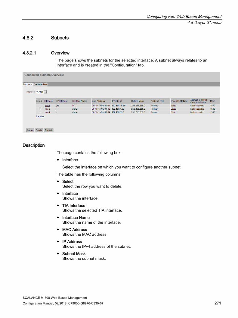
Configuring with Web Based Management 4.8 "Layer 3" menu
SCALANCE M-800 Web Based Management Configuration Manual, 02/2018, C79000-G8976-C330-07 271
4.8.2 Subnets
4.8.2.1 Overview The page shows the subnets for the selected interface. A subnet always relates to an interface and is created in the "Configuration" tab.
Description The page contains the following box:
● Interface
Select the interface on which you want to configure another subnet.
The table has the following columns:
● Select Select the row you want to delete.
● Interface Shows the interface.
● TIA Interface Shows the selected TIA interface.
● Interface Name Shows the name of the interface.
● MAC Address Shows the MAC address.
● IP Address Shows the IPv4 address of the subnet.
● Subnet Mask Shows the subnet mask.

Configuring with Web Based Management 4.8 "Layer 3" menu
SCALANCE M-800 Web Based Management 272 Configuration Manual, 02/2018, C79000-G8976-C330-07
● Address Type Shows the address type. The following values are possible:
– Primary The first IPv4 address that was configured on the IPv4 interface.
– Secondary
All other IPv4 addresses that were configured on the IPv4 interface.
● IP Assignment Method Shows how the IPv4 address is assigned. The following values are possible:
– Static The IPv4 address is static. You enter the settings in "IP Address" and "Subnet Mask".
– Dynamic (DHCP) The device obtains a dynamic IPv4 address from a DHCPv4 server.
Configuring with Web Based Management 4.8 "Layer 3" menu
SCALANCE M-800 Web Based Management Configuration Manual, 02/2018, C79000-G8976-C330-07 273
● Address Collision Detection Status
If new IPv4 addresses become active in the network, the "Address Collision Detection" function checks whether this can result in address collisions. That allows IPv4 addresses that would be assigned twice to be detected.
Note
The function does not run a cyclic check.
This column shows the current status of the function. The following values are possible:
– Idle
The interface is not enabled and does not have an IPv4 address.
– Starting
This status indicates the start-up phase. In this phase, the device initially sends a query as to whether the planned IPv4 address already exists. If the address is not yet been assigned, the device sends the message that it is using this IP address as of now.
– Conflict
The interface is not enabled. The interface is attempting to use an IPv4 address that has already been assigned.
– Defending
The interface uses a unique IPv4 address. Another interface is attempting to use the same IPv4 address.
– Active
The interface uses a unique IPv4 address. There are no collisions.
– Not supported
The function for detection of address collisions is not supported.
– Disabled
The function for detection of address collisions is disabled.
● MTU Shows the packet size.

Configuring with Web Based Management 4.8 "Layer 3" menu
SCALANCE M-800 Web Based Management 274 Configuration Manual, 02/2018, C79000-G8976-C330-07
4.8.2.2 Configuration On this page, you configure the subnet for the interface.
Description The page contains the following:
● Interface (Name) Select the interface from the drop-down list.
● Interface Name Enter the name of the interface.
● MAC Address
Displays the MAC address of the selected interface.
● DHCP
Enable or disable the DHCP client for this IPv4 interface.
Note
If you want to operate the device as a router with several interfaces, disable DHCP on all interfaces.
● IP Address Enter the IPv4 address of the interface. The IPv4 addresses must not be used more than once.
● Subnet Mask Enter the subnet mask of the subnet you are creating. Subnets on different interfaces must not overlap.
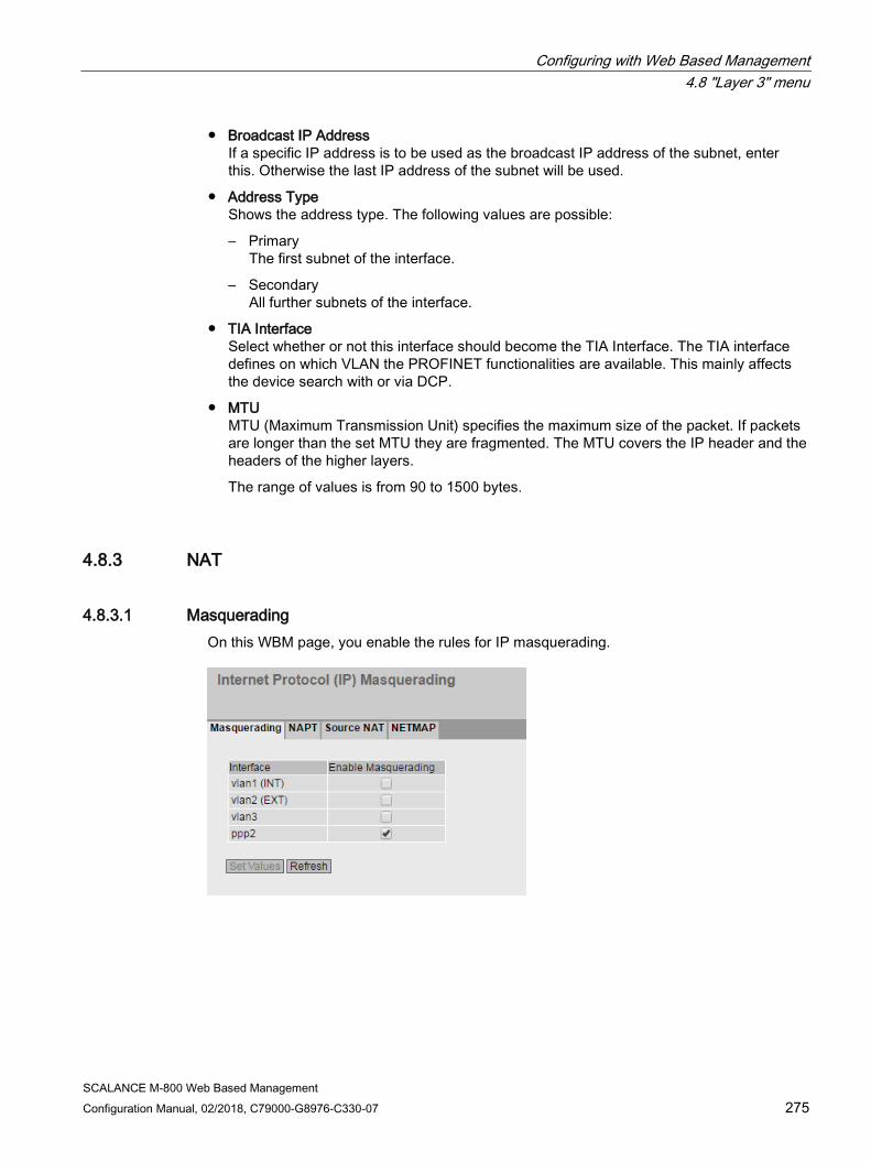
Configuring with Web Based Management 4.8 "Layer 3" menu
SCALANCE M-800 Web Based Management Configuration Manual, 02/2018, C79000-G8976-C330-07 275
● Broadcast IP Address If a specific IP address is to be used as the broadcast IP address of the subnet, enter this. Otherwise the last IP address of the subnet will be used.
● Address Type Shows the address type. The following values are possible:
– Primary The first subnet of the interface.
– Secondary All further subnets of the interface.
● TIA Interface Select whether or not this interface should become the TIA Interface. The TIA interface defines on which VLAN the PROFINET functionalities are available. This mainly affects the device search with or via DCP.
● MTU MTU (Maximum Transmission Unit) specifies the maximum size of the packet. If packets are longer than the set MTU they are fragmented. The MTU covers the IP header and the headers of the higher layers.
The range of values is from 90 to 1500 bytes.
4.8.3 NAT
4.8.3.1 Masquerading On this WBM page, you enable the rules for IP masquerading.

Configuring with Web Based Management 4.8 "Layer 3" menu
SCALANCE M-800 Web Based Management 276 Configuration Manual, 02/2018, C79000-G8976-C330-07
Description The table has the following columns:
● Interface
Interface to which the setting relates. Only interfaces with a configured subnet are available.
● Enable Masquerading
When enabled, with each outgoing data packet sent via this interface, the source IP address is replaced by the IP address of the interface.
4.8.3.2 NAPT On this WBM page, you configure port forwarding.
Description The page contains the following boxes:
● Source Interface
Select the the interface for which you want to create further NAT configurations. Can only be selected if the device has several interfaces.
● Traffic Type
Specify the protocol for which the address assignment is valid.
● Use Interface IP from Source Interface
When enabled, the IP address of the selected interface is used for "Dest IP Address".

Configuring with Web Based Management 4.8 "Layer 3" menu
SCALANCE M-800 Web Based Management Configuration Manual, 02/2018, C79000-G8976-C330-07 277
● Destination IP Address
Enter the destination IP address. The frames are received at this IP address. Can only be edited if "Use Interface IP from Source Interface" is disabled.
● Destination Port
Enter the destination port. Incoming frames with this port as the destination port are forwarded. If the setting is intended to apply to a port range, enter the range with start port "-" end port, for example 30 - 40.
● Translated Destination IP
Enter the IP address of the node to which this frame will be forwarded.
● Translated Destination Port
Enter the number of the port. This is the new destination port to which the incoming frame will be forwarded. If the setting is intended to apply to a port range, enter the range with start port "-" end port, for example 30 - 40.
If the "Destination Port" and the "Translated Destination Port" are the same, the frames are forwarded without port translation.
Note
If the port is already occupied by a local service, for example Telnet, a warning is displayed. Make sure that you avoid using the following ports: • Telnet: TCP port 23 • SSH: TCP port 23 • HTTP: TCP port 80 • HTTPS: TCP port 443 • SNMP: UDP port 161 • ISAKMP: UDP port 500 • IPsec Nat-T: UDP port 4500 • NTP: UDP port 123
The table has the following columns:
● Select
Select the check box in the row to be deleted.
● Source Interface
Shows the interface from which the packets need to come. Only these packets are considered for port forwarding.
● Traffic Type
Shows the protocol for which the address assignment applies.
● Interface IP
Shows whether the IP address of the interface is used.
● Destination IP
Shows the destination IP address. The frames are received at this IP address.
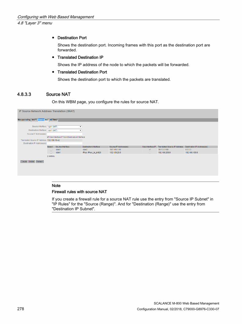
Configuring with Web Based Management 4.8 "Layer 3" menu
SCALANCE M-800 Web Based Management 278 Configuration Manual, 02/2018, C79000-G8976-C330-07
● Destination Port
Shows the destination port. Incoming frames with this port as the destination port are forwarded.
● Translated Destination IP
Shows the IP address of the node to which the packets will be forwarded.
● Translated Destination Port
Shows the destination port to which the packets are translated.
4.8.3.3 Source NAT On this WBM page, you configure the rules for source NAT.
Note Firewall rules with source NAT
If you create a firewall rule for a source NAT rule use the entry from "Source IP Subnet" in "IP Rules" for the "Source (Range)". And for "Destination (Range)" use the entry from "Destination IP Subnet".
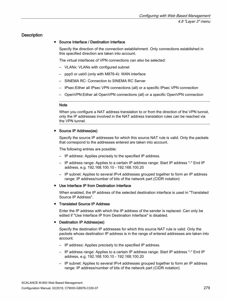
Configuring with Web Based Management 4.8 "Layer 3" menu
SCALANCE M-800 Web Based Management Configuration Manual, 02/2018, C79000-G8976-C330-07 279
Description ● Source Interface / Destination Interface
Specify the direction of the connection establishment. Only connections established in this specified direction are taken into account.
The virtual interfaces of VPN connections can also be selected:
– VLANx: VLANs with configured subnet
– ppp0 or usb0 (only with M876-4): WAN interface
– SINEMA RC: Connection to SINEMA RC Server
– IPsec:Either all IPsec VPN connections (all) or a specific IPsec VPN connection
– OpenVPN:Either all OpenVPN connections (all) or a specific OpenVPN connection
Note
When you configure a NAT address translation to or from the direction of the VPN tunnel, only the IP addresses involved in the NAT address translation rules can be reached via the VPN tunnel.
● Source IP Address(es)
Specify the source IP addresses for which this source NAT rule is valid. Only the packets that correspond to the addresses entered are taken into account.
The following entries are possible:
– IP address: Applies precisely to the specified IP address.
– IP address range: Applies to a certain IP address range: Start IP address "-" End IP address, e.g. 192.168.100.10 - 192.168.100.20
– IP subnet: Applies to several IPv4 addresses grouped together to form an IP address range: IP address/number of bits of the network part (CIDR notation)
● Use Interface IP from Destination Interface
When enabled, the IP address of the selected destination interface is used in "Translated Source IP Address".
● Translated Source IP Address
Enter the IP address with which the IP address of the sender is replaced. Can only be edited if "Use Interface IP from Destination Interface" is disabled.
● Destination IP Address(es)
Specify the destination IP addresses for which this source NAT rule is valid. Only the packets whose destination IP address is in the range of entered addresses are taken into account.
– IP address: Applies precisely to the specified IP address.
– IP address range: Applies to a certain IP address range: Start IP address "-" End IP address, e.g. 192.168.100.10 - 192.168.100.20
– IP subnet: Applies to several IPv4 addresses grouped together to form an IP address range: IP address/number of bits of the network part (CIDR notation)
Configuring with Web Based Management 4.8 "Layer 3" menu
SCALANCE M-800 Web Based Management 280 Configuration Manual, 02/2018, C79000-G8976-C330-07
The table has the following columns:
● Select Activate the check box in the row to be deleted.
● Source Interface
Shows the source interface.
● Destination Interface
Shows the destination interface.
● Source IP Address(es)
Shows the IP addresses of the senders for which address translation is required.
● Translated Source IP Address Shows the IP address with which the IP address of the sender is replaced.
● Destination IP Address(es) Shows the IP addresses of the recipients for which address translation is required.
4.8.3.4 NETMAP On this WBM page, you specify the rules for NETMAP. NETMAP is static 1:1 mapping of network addresses in which the host part is retained. For more information, refer to the section "NAT and firewall".
Note Firewall rules with source NAT
If you create a firewall rule for a source NAT rule use the entry from "Source IP Subnet" in "IP Rules" for the "Source (Range)". And for "Destination (Range)" use the entry from "Destination IP Subnet". Firewall rules with destination NAT
If you create a corresponding firewall rule for a destination NAT rule, use the entry from "Source IP Subnet" in "IP Rules" for the "Source (Range)". And for "Destination (Range)" use the entry from "Destination IP Subnet".
Configuring with Web Based Management 4.8 "Layer 3" menu
SCALANCE M-800 Web Based Management Configuration Manual, 02/2018, C79000-G8976-C330-07 281
Description ● Type
Specify the type of address translation.
– Source: Replacement of the source IP address
– Destination: Replacement of the destination IP address
● Source Interface
Specify the source interface.
– VLANx: VLANs with configured subnet
– ppp0 or usb0 (only with M876-4): WAN interface
– SINEMA RC: Connection to SINEMA RC Server
– IPsec: Either all IPsec VPN connections (all) or a specific IPsec VPN connection
– OpenVPN:Either all OpenVPN connections (all) or a specific OpenVPN connection
● Destination Interface
Specify the destination interface.
– VLANx: VLANs with configured subnet
– SINEMA RC: Connection to SINEMA RC Server
– IPsec: Either all IPsec VPN connections (all) or a specific IPsec VPN connection
– OpenVPN:Either all OpenVPN connections (all) or a specific OpenVPN connection
● Source IP Subnet
Enter the subnet of the sender. The subnet can also be a single PC or another subset of the subnet. Use the CIDR notation.
● Translated Source IP Subnet
Enter the subnet with which the subnet of the sender will be replaced. Can only be edited with the setting "Source". The subnet can also be a single PC or another subset of the subnet. Use the CIDR notation.
● Destination IP Subnet
Enter the subnet of the recipient. The subnet can also be a single PC or another subset of the subnet. Use the CIDR notation.
● Translated Destination IP Subnet
Enter the subnet with which the subnet of the recipient will be replaced. Can only be edited with the setting "Destination". The subnet can also be a single PC or another subset of the subnet. Use the CIDR notation.

Configuring with Web Based Management 4.8 "Layer 3" menu
SCALANCE M-800 Web Based Management 282 Configuration Manual, 02/2018, C79000-G8976-C330-07
The table has the following columns:
● Select
Select the check box in the row to be deleted.
● Type
Shows the direction of the address translation.
● Source Interface
Shows the source interface.
● Destination Interface
Shows the destination interface.
● Source IP Subnet
Shows the subnet of the sender.
● Translated Source IP Subnet
Shows the subnet of the sender with which the subnet of the sender is replaced.
● Destination IP Subnet
Shows the subnet of the recipient.
● Translated Destination IP Subnet
Shows the subnet of the recipient with which the subnet of the recipient is replaced.
4.8.4 VRRPv3
4.8.4.1 Routers
Introduction Using the "Create" button, you can create new virtual routers. A maximum of 2 virtual routers can be configured. You can configure other parameters on the "Configuration" tab.
Note • You can use VRRPv3 on VLAN interfaces.
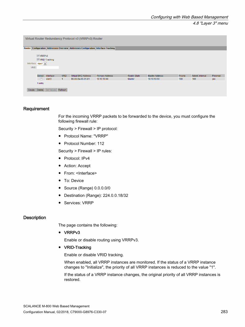
Configuring with Web Based Management 4.8 "Layer 3" menu
SCALANCE M-800 Web Based Management Configuration Manual, 02/2018, C79000-G8976-C330-07 283
Requirement For the incoming VRRP packets to be forwarded to the device, you must configure the following firewall rule:
Security > Firewall > IP protocol:
● Protocol Name: "VRRP"
● Protocol Number: 112
Security > Firewall > IP rules:
● Protocol: IPv4
● Action: Accept
● From: <Interface>
● To: Device
● Source (Range) 0.0.0.0/0
● Destination (Range): 224.0.0.18/32
● Services: VRRP
Description The page contains the following:
● VRRPv3
Enable or disable routing using VRRPv3.
● VRID-Tracking
Enable or disable VRID tracking.
When enabled, all VRRP instances are monitored. If the status of a VRRP instance changes to "Initialize", the priority of all VRRP instances is reduced to the value "1".
If the status of a VRRP instance changes, the original priority of all VRRP instances is restored.
Configuring with Web Based Management 4.8 "Layer 3" menu
SCALANCE M-800 Web Based Management 284 Configuration Manual, 02/2018, C79000-G8976-C330-07
● Interface
Select the required VLAN interface operating as virtual router.
● VRID
Enter the ID of the virtual router. This ID defines the group of routers that form a virtual router (VR). In the group, this is the same. It can no longer be used for other groups. Valid values are 1.. 255.
The table has the following columns:
● Select
Select the check box in the row to be deleted.
● Interface
Shows the Interface that functions as the virtual router.
● VRID
Shows the ID of the virtual router.
● Virtual MAC Address
Shows the virtual MAC address of the virtual router.
● Primary IP Address
Shows the numerically lowest IPv4 address in this VLAN. The entry 0.0.0.0 means that the "Primary" address on this VLAN is used. Otherwise all IPv4 addresses configured on this VLAN in the "Layer 3 (IPv4) > Subnets" menu are valid values.
● Router State
Shows the current status of the virtual router. Possible values are:
– Master
The router is the master router and handles the routing functionality for all assigned IPv4 addresses.
– Backup
The router is the backup router. If the master router fails, the backup router takes over the tasks of the master router.
– Initialize
The virtual router has just been turned on. It will soon change to the "Master" or "Backup" status.
● Master IP Address
Shows the IPv4 address of the master router.
● Priority
Shows the priority of the virtual router. Valid values are 1-254. If an IPv4 address is assigned to the VRRP router that is also actually configured on the local IPv4 interface, the value 255 is entered automatically. All other priorities can be distributed freely among the VRRP routers. The higher the priority, the earlier the VRRP router becomes "Master".

Configuring with Web Based Management 4.8 "Layer 3" menu
SCALANCE M-800 Web Based Management Configuration Manual, 02/2018, C79000-G8976-C330-07 285
● Advert. Internal
Shows the interval at which the master router sends VRRPv3 packets.
● Preempt
Shows the precedence of a router when changing roles between backup and master.
– yes
This router has precedence when changing roles.
– no
This router does not have precedence when changing roles.
VRRP and DHCP server If you want to operate a DHCP server on the devices of a VRRP group, the DHCP server must be configured on the master router. Backup routers do not react to DHCP queries. Make sure that the master router is statically configured and that after a failure, becomes the master of the VRRP group again.
Procedure 1. Select the "VRRPv3" check box.
2. Select the required interface.
3. Enter the ID of the virtual router in the "VRID" input box.
4. Click the "Create" button. A new row is inserted in the table.
5. Select the "VRID Tracking" check box to monitor the VRID.
6. Click the "Set Values" button. To configure the virtual router, click on the "Configuration" tab.
4.8.4.2 Configuration

Configuring with Web Based Management 4.8 "Layer 3" menu
SCALANCE M-800 Web Based Management 286 Configuration Manual, 02/2018, C79000-G8976-C330-07
Introduction On this page, you configure the virtual router.
Description The page contains the following:
● Interface / VRID
Select the ID of the virtual router to be configured.
● Primary Address
Select the primary IPv4 address. If the router becomes master router, the router uses this IPv4 address.
Note
If you only configure one subnet on this VLAN, no entry is necessary. The entry is then 0.0.0.0. If you configure more than one subnet on the VLAN and you want a specific IPv4 address to be used as the source address for VRRP packets, select the IPv4 address. Otherwise, the numerically lowest IPv4 address will be used.
● Priority
Enter the priority of this virtual router. Valid values are 1-254. If an IPv4 address is assigned to the VRRPv3 router that is also actually configured on the local IPv4 interface, the value 255 is entered automatically. All other priorities can be distributed freely among the VRRPv3 routers. The higher the priority, the earlier the VRRPv3 router becomes "Master".
● Advertisement interval
Enter the interval in seconds after which a master router sends a VRRPv3 packet again.
● Track ID Select a track ID.
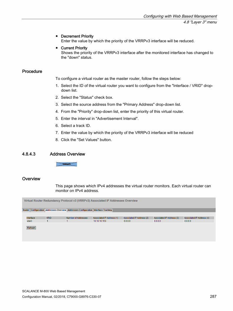
Configuring with Web Based Management 4.8 "Layer 3" menu
SCALANCE M-800 Web Based Management Configuration Manual, 02/2018, C79000-G8976-C330-07 287
● Decrement Priority Enter the value by which the priority of the VRRPv3 interface will be reduced.
● Current Priority Shows the priority of the VRRPv3 interface after the monitored interface has changed to the "down" status.
Procedure To configure a virtual router as the master router, follow the steps below:
1. Select the ID of the virtual router you want to configure from the "Interface / VRID" drop-down list.
2. Select the "Status" check box.
3. Select the source address from the "Primary Address" drop-down list.
4. From the "Priority" drop-down list, enter the priority of this virtual router.
5. Enter the interval in "Advertisement Interval".
6. Select a track ID.
7. Enter the value by which the priority of the VRRPv3 interface will be reduced
8. Click the "Set Values" button.
4.8.4.3 Address Overview
Overview This page shows which IPv4 addresses the virtual router monitors. Each virtual router can monitor on IPv4 address.

Configuring with Web Based Management 4.8 "Layer 3" menu
SCALANCE M-800 Web Based Management 288 Configuration Manual, 02/2018, C79000-G8976-C330-07
Description of the displayed values The table has the following columns:
● Interface
Shows the Interface that functions as the virtual router.
● VRID
Shows the ID of this virtual router.
● Number of Addresses
Shows the number of IPv4 addresses.
● Associated IP Address (1) ...Associated IP Address (4)
Shows the router IPv4 addresses monitored by this virtual router. If a router takes over the role of master, the routing function is taken over by this router for all these IPv4 addresses.
4.8.4.4 Address Configuration
Creating or changing the monitored IP addresses On this page, you can create, modify or delete the IPv4 addresses to be monitored. Each virtual router can monitor on IPv4 address.
Configuring with Web Based Management 4.8 "Layer 3" menu
SCALANCE M-800 Web Based Management Configuration Manual, 02/2018, C79000-G8976-C330-07 289
Description The page contains the following:
● Interface / VRID
Select the ID of the virtual router.
● Associated IP Address
Enter the IPv4 address that the virtual router will monitor.
The table has the following columns:
● Select
Select the check box in the row to be deleted
● Associated IP Address
Shows the IPv4 addresses that the virtual router monitors.
Procedure 1. Select the ID of the virtual router.
2. Enter the IPv4 address that the virtual router will monitor.
3. Click the "Create" button. A new entry is generated in the table.
4.8.4.5 Interface Tracking
Introduction On this page, you configure the monitoring of interfaces.
When the link of a monitored interface changes from "up" to "down", the priority of the assigned VRRP interface is reduced. You configure the value by which the priority is reduced on the page "Layer 3 > VRRPv3 > Configuration".
When the link of the interface changes back from "down" to "up", the original priority of the VRRP interface is restored.
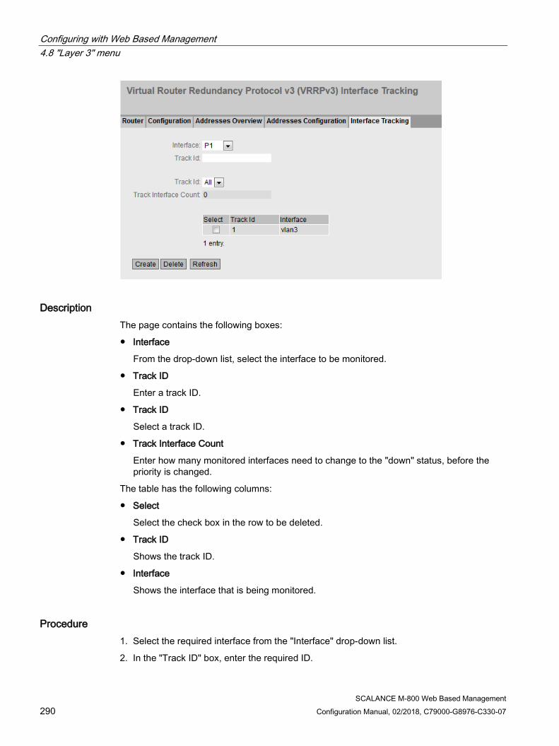
Configuring with Web Based Management 4.8 "Layer 3" menu
SCALANCE M-800 Web Based Management 290 Configuration Manual, 02/2018, C79000-G8976-C330-07
Description The page contains the following boxes:
● Interface
From the drop-down list, select the interface to be monitored.
● Track ID
Enter a track ID.
● Track ID
Select a track ID.
● Track Interface Count
Enter how many monitored interfaces need to change to the "down" status, before the priority is changed.
The table has the following columns:
● Select
Select the check box in the row to be deleted.
● Track ID
Shows the track ID.
● Interface
Shows the interface that is being monitored.
Procedure 1. Select the required interface from the "Interface" drop-down list.
2. In the "Track ID" box, enter the required ID.
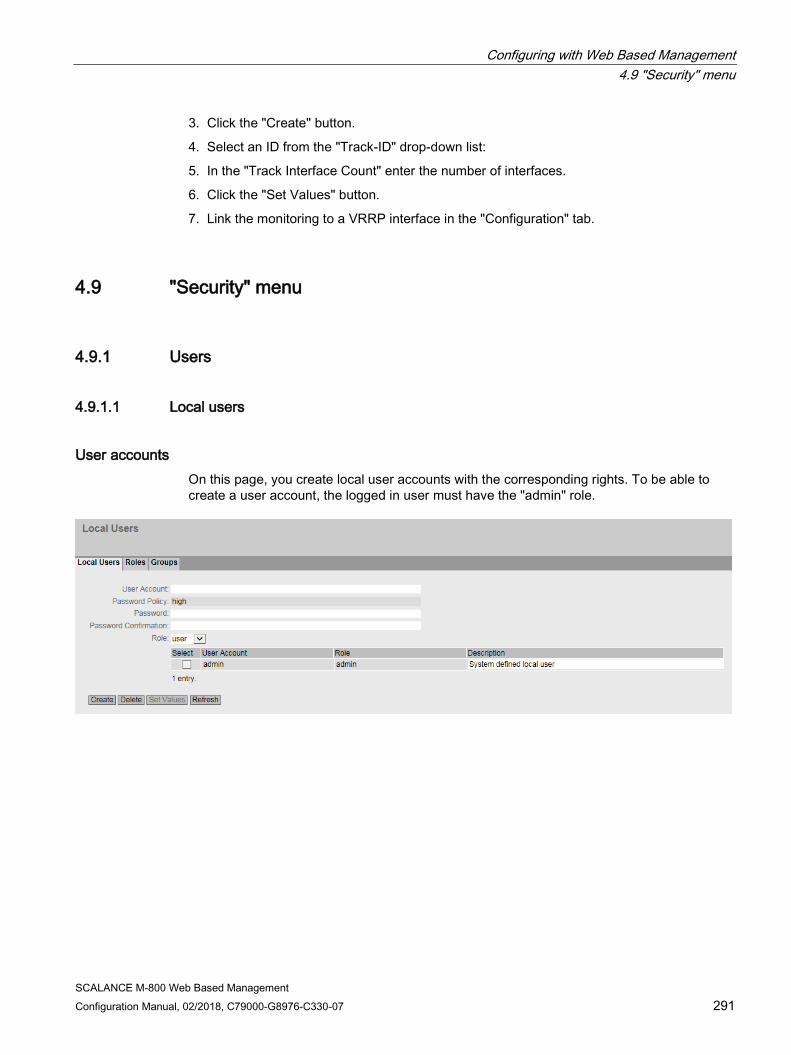
Configuring with Web Based Management 4.9 "Security" menu
SCALANCE M-800 Web Based Management Configuration Manual, 02/2018, C79000-G8976-C330-07 291
3. Click the "Create" button.
4. Select an ID from the "Track-ID" drop-down list:
5. In the "Track Interface Count" enter the number of interfaces.
6. Click the "Set Values" button.
7. Link the monitoring to a VRRP interface in the "Configuration" tab.
4.9 "Security" menu
4.9.1 Users
4.9.1.1 Local users
User accounts On this page, you create local user accounts with the corresponding rights. To be able to create a user account, the logged in user must have the "admin" role.
Configuring with Web Based Management 4.9 "Security" menu
SCALANCE M-800 Web Based Management 292 Configuration Manual, 02/2018, C79000-G8976-C330-07
Description The page contains the following:
● Account
Enter the name for the user. The name must meet the following conditions:
– It must be unique.
– It must be between 1 and 250 characters long.
– The following characters must not be included: § ? " ; :
– The following user names are not allowed: admin, user, service, debug
Note
User name cannot be changed
After creating a user, the user name can no longer be modified.
If a user name needs to be changed, the user must be deleted and a new user created.
Note User names: admin, service, debug
When shipped the following user names are predefined in the factory. admin, service, debug • admin: You can configure the device with this user name. If you log on the first time or
log on after a "Restore Factory Defaults and Restart", you will be prompted to change the predefined password "admin".
• service, debug: These user names are reserved for service purposes.
● Password Policy
Shows which password policy is being used.
– High
Password length: at least 8 characters, maximum 128 characters
At least 1 uppercase letter
At least 1 special character
At least 1 number
– Low
Password length: at least 6 characters, maximum 128 characters
You configure the password policy on the page "Security > Passwords > Options".
● Password
Enter the password. The strength of the password depends on the set password policy.
Configuring with Web Based Management 4.9 "Security" menu
SCALANCE M-800 Web Based Management Configuration Manual, 02/2018, C79000-G8976-C330-07 293
● Password Confirmation
Enter the password again to confirm it.
● Role
Select a role.
You can choose between default and self-defined roles, refer to the page "Security > Users > Roles.".
The table contains the following columns:
● Select
Select the check box in the row to be deleted.
Note
The preset users as well as logged in users cannot be deleted or changed.
● Account
Shows the user name.
● Role
Shows the role of the user.
● Description
Displays a description of the user account. The description text can be up to 100 characters long.
Procedure Creating users
1. Enter the name for the user.
2. Enter the password for the user.
3. Enter the password again to confirm it.
4. Select the role of the user.
5. Click the "Create" button.
6. Enter a description of the user.
7. Click the "Set Values" button.
Deleting users
1. Select the check box in the row to be deleted.
2. Click the "Delete" button. The entries are deleted and the page is updated.

Configuring with Web Based Management 4.9 "Security" menu
SCALANCE M-800 Web Based Management 294 Configuration Manual, 02/2018, C79000-G8976-C330-07
4.9.1.2 Roles
Roles On this page, you create roles that are valid locally on the device.
Note
The values displayed depend on the rights of the logged-in user.
Description The page contains the following:
● Role Name
Enter the name for the role. The name must meet the following conditions:
– It must be unique.
– It must be between 1 and 64 characters long.
Note
Role name cannot be changed
After creating a role, the name of the role can no longer be changed.
If a name of a role needs to be changed, the role must be deleted and a new role created.
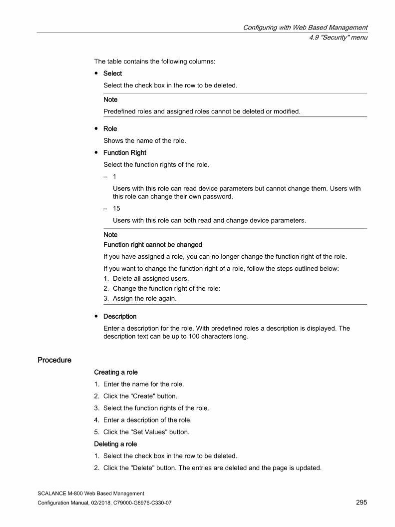
Configuring with Web Based Management 4.9 "Security" menu
SCALANCE M-800 Web Based Management Configuration Manual, 02/2018, C79000-G8976-C330-07 295
The table contains the following columns:
● Select
Select the check box in the row to be deleted.
Note
Predefined roles and assigned roles cannot be deleted or modified.
● Role
Shows the name of the role.
● Function Right
Select the function rights of the role.
– 1
Users with this role can read device parameters but cannot change them. Users with this role can change their own password.
– 15
Users with this role can both read and change device parameters.
Note Function right cannot be changed
If you have assigned a role, you can no longer change the function right of the role.
If you want to change the function right of a role, follow the steps outlined below: 1. Delete all assigned users. 2. Change the function right of the role: 3. Assign the role again.
● Description
Enter a description for the role. With predefined roles a description is displayed. The description text can be up to 100 characters long.
Procedure Creating a role
1. Enter the name for the role.
2. Click the "Create" button.
3. Select the function rights of the role.
4. Enter a description of the role.
5. Click the "Set Values" button.
Deleting a role
1. Select the check box in the row to be deleted.
2. Click the "Delete" button. The entries are deleted and the page is updated.
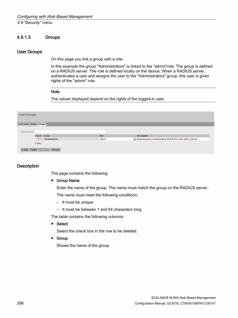
Configuring with Web Based Management 4.9 "Security" menu
SCALANCE M-800 Web Based Management 296 Configuration Manual, 02/2018, C79000-G8976-C330-07
4.9.1.3 Groups
User Groups On this page you link a group with a role.
In this example the group "Administrators" is linked to the "admin"role: The group is defined on a RADIUS server. The role is defined locally on the device. When a RADIUS server authenticates a user and assigns the user to the "Administrators" group, this user is given rights of the "admin" role.
Note
The values displayed depend on the rights of the logged-in user.
Description The page contains the following:
● Group Name
Enter the name of the group. The name must match the group on the RADIUS server.
The name must meet the following conditions:
– It must be unique.
– It must be between 1 and 64 characters long.
The table contains the following columns:
● Select
Select the check box in the row to be deleted.
● Group
Shows the name of the group.

Configuring with Web Based Management 4.9 "Security" menu
SCALANCE M-800 Web Based Management Configuration Manual, 02/2018, C79000-G8976-C330-07 297
● Role
Select a role. Users who are authenticated with the linked group on the RADIUS server receive the rights of this role locally on the device.
You can choose between system-defined and self-defined roles, refer to the page "Security > Users > Roles.".
● Description
Enter a description for the link of the group.to a role. The description text can be up to 100 characters long.
Procedure Linking a group to a role.
1. Enter the name of a group.
2. Click the "Create" button.
3. Select a role.
4. Enter a description for the link of a group.to a role.
5. Click the "Set Values" button.
Deleting the link between a group and a role
1. Select the check box in the row to be deleted.
2. Click the "Delete" button. The entries are deleted and the page is updated.
4.9.2 Passwords
Configuration of the passwords

Configuring with Web Based Management 4.9 "Security" menu
SCALANCE M-800 Web Based Management 298 Configuration Manual, 02/2018, C79000-G8976-C330-07
A user with the "admin" role can change the password of already created users. With the "user" role, users can only change their own password.
Description The page contains the following:
● Current User
Shows the user that is currently logged in.
● Current User Password
Enter the password for the currently logged in user.
● Account
Select the user whose password you want to change.
● Password Policy
Shows which password policy is being used when assigning new passwords.
– High
Password length: at least 8 characters, maximum 128 characters
At least 1 uppercase letter
At least 1 special character
At least 1 number
– Low
Password length: at least 6 characters, maximum 128 characters
● New Password
Enter the new password for the selected user.
The following character must not be included: §
Note
When you log in for the first time or following a "Restore Factory Defaults and Restart", with the preset user "admin" you will be prompted to change the password.
The factory setting for the password when the devices ship is as follows: • admin: admin
Note
Changing the password in Trial mode
Even if you change the password in Trial mode, this change is saved immediately.
● Password Confirmation
Enter the new password again to confirm it.
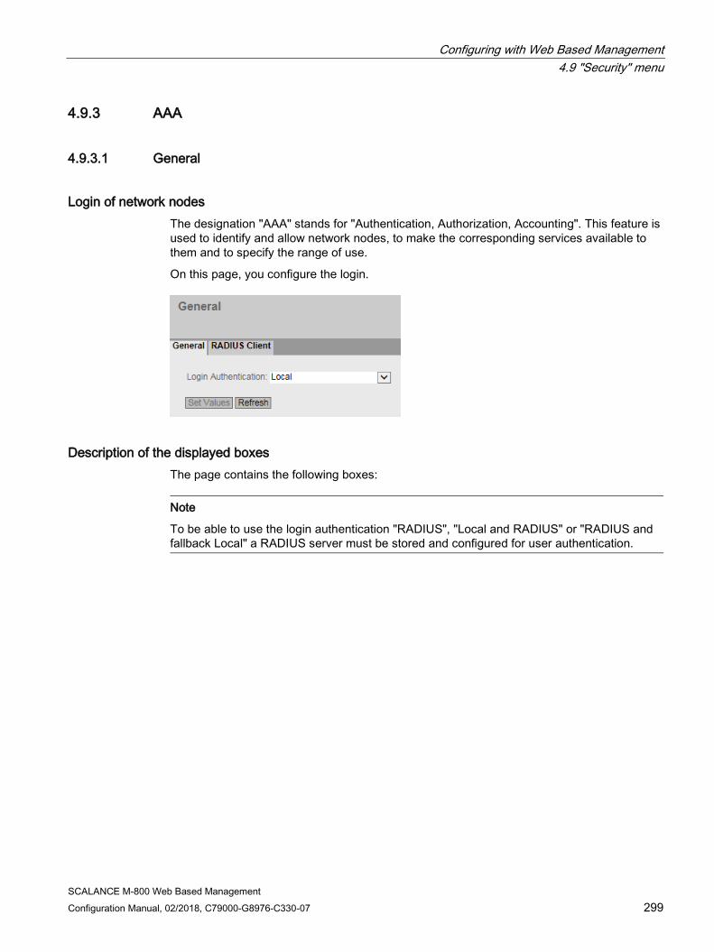
Configuring with Web Based Management 4.9 "Security" menu
SCALANCE M-800 Web Based Management Configuration Manual, 02/2018, C79000-G8976-C330-07 299
4.9.3 AAA
4.9.3.1 General
Login of network nodes The designation "AAA" stands for "Authentication, Authorization, Accounting". This feature is used to identify and allow network nodes, to make the corresponding services available to them and to specify the range of use.
On this page, you configure the login.
Description of the displayed boxes The page contains the following boxes:
Note
To be able to use the login authentication "RADIUS", "Local and RADIUS" or "RADIUS and fallback Local" a RADIUS server must be stored and configured for user authentication.
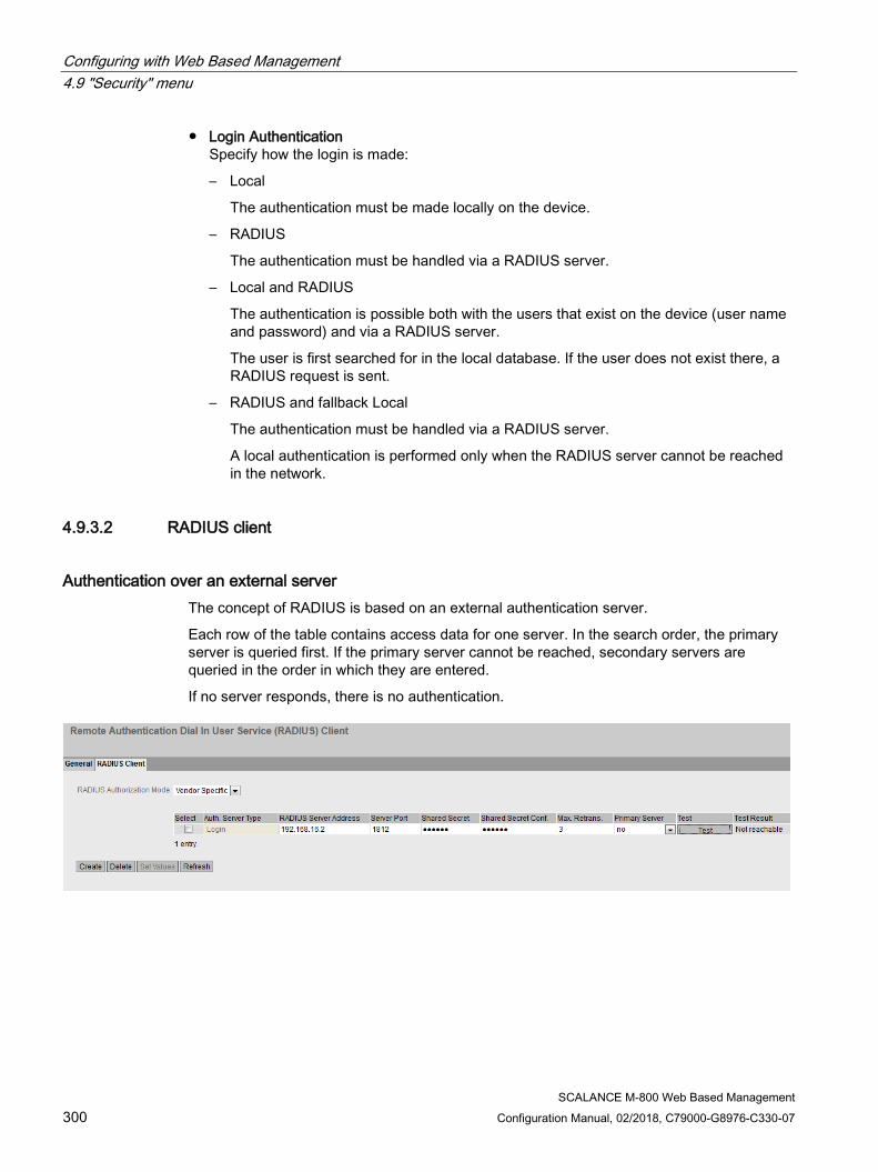
Configuring with Web Based Management 4.9 "Security" menu
SCALANCE M-800 Web Based Management 300 Configuration Manual, 02/2018, C79000-G8976-C330-07
● Login Authentication Specify how the login is made:
– Local
The authentication must be made locally on the device.
– RADIUS
The authentication must be handled via a RADIUS server.
– Local and RADIUS
The authentication is possible both with the users that exist on the device (user name and password) and via a RADIUS server.
The user is first searched for in the local database. If the user does not exist there, a RADIUS request is sent.
– RADIUS and fallback Local
The authentication must be handled via a RADIUS server.
A local authentication is performed only when the RADIUS server cannot be reached in the network.
4.9.3.2 RADIUS client
Authentication over an external server The concept of RADIUS is based on an external authentication server.
Each row of the table contains access data for one server. In the search order, the primary server is queried first. If the primary server cannot be reached, secondary servers are queried in the order in which they are entered.
If no server responds, there is no authentication.
Configuring with Web Based Management 4.9 "Security" menu
SCALANCE M-800 Web Based Management Configuration Manual, 02/2018, C79000-G8976-C330-07 301
Description of the displayed boxes The page contains the following boxes:
● RADIUS Authorization Mode
For the login authentication, the RADIUS authorization mode specifies how the rights are assigned to the user with a successful authentication.
– Conventional
In this mode the user is logged in with administrator rights if the server returns the value "Administrative User" to the device for the attribute "Service Type". In all other cases the user is logged in with read rights.
– SiemensVSA
In this mode the assignment of rights depends on whether and which group the server returns for the user and whether or not there is an entry for the user in the table "External User Accounts".
The table has the following columns:
● Select Select the row you want to delete.
● RADIUS Server Address Enter the IPv4 address or the FQDN (Fully Qualified Domain Name) of the RADIUS server.
● Server Port Here, enter the input port on the RADIUS server. As default, input port 1812 is set. The range of values is 1 to 65535.
● Shared Secret Enter your access ID here. The range of values is 1...128 characters
● Shared Secret Conf. Enter your access ID again as confirmation.
● Max. Retrans.
Here, enter the maximum number of retries for an attempted request.
The initial connection attempt is repeated the number of times specified here before another configured RADIUS server is queried or the login counts as having failed. As default 3 retries are set, this means 4 connection attempts. The range of values is 1 to 5.
● Primary Server Using the options in the drop-down list, specify whether or not this server is the primary server. You can select one of the options "yes" or "no".
Configuring with Web Based Management 4.9 "Security" menu
SCALANCE M-800 Web Based Management 302 Configuration Manual, 02/2018, C79000-G8976-C330-07
● Test With this button, you can test whether or not the specified RADIUS server is available. The test is performed once and not repeated cyclically.
● Test Result
Shows whether or not the RADIUS server is available:
– Not reachable
The IP address is not reachable.
The IP address is reachable, the RADIUS server is, however, not running.
– Reachable, key not accepted
The IP address is reachable, the RADIUS server does not, however accept the shared secret.
– Reachable, key accepted
The IP address is reachable, the RADIUS server accepts the specified shared secret.
Steps in configuration Entering a new server
1. Click the "Create" button. A new entry is generated in the table. The following default values are entered in the table:
– RADIUS Server Address: 0.0.0.0
– Server Port: 1812
– Max. Retrans.: 3
– Primary server: No
2. In the relevant row, enter the following data in the input boxes:
– RADIUS Server Address
– Server Port
– Shared Secret
– Shared Secret Conf
– Max. Retrans.: 3
– Primary server: No
3. If necessary check the reachability of the RADIUS server.
4. Click the "Set Values" button.
Repeat this procedure for every server you want to enter.
Configuring with Web Based Management 4.9 "Security" menu
SCALANCE M-800 Web Based Management Configuration Manual, 02/2018, C79000-G8976-C330-07 303
Modifying servers
1. In the relevant row, enter the following data in the input boxes:
– RADIUS Server Address
– Server Port
– Shared Secret
– Shared Secret Conf
– Max. Retrans.
– Primary Server
2. If necessary check the reachability of the RADIUS server.
3. Click the "Set Values" button.
Repeat this procedure for every server whose entry you want to modify
Deleting servers
1. Click the check box in the first column before the row you want to delete to select the entry for deletion. Repeat this for all entries you want to delete.
2. Click the "Delete" button. The data is deleted from the memory of the device and the page is updated.
4.9.4 Certificates
4.9.4.1 Overview All loaded files (certificates and keys) are shown on this WBM page. You have the following options for loading files on the device:
● System > Load&Save > HTTP
● System > Load&Save > TFTP
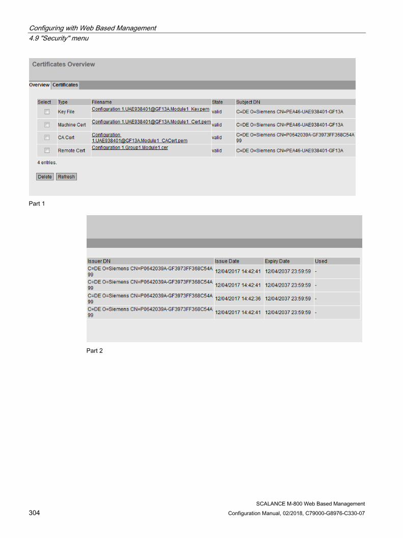
Configuring with Web Based Management 4.9 "Security" menu
SCALANCE M-800 Web Based Management 304 Configuration Manual, 02/2018, C79000-G8976-C330-07
Part 1
Part 2

Configuring with Web Based Management 4.9 "Security" menu
SCALANCE M-800 Web Based Management Configuration Manual, 02/2018, C79000-G8976-C330-07 305
Description ● Select
Select the check box in the row to be deleted. Only unused certificates can be deleted.
● Type Shows the type of the loaded file.
– CA Cert The CA certificate is signed by a CA (Certification Authority).
– Machine certificate
– Key File
– Remote Cert Partner certificate
● Filename
Shows the file name.
● Status
Shows whether the certificate is valid or has already expired.
● Subject DN
Shows the name of the applicant.
● Issuer DN
Shows the name of the certificate issuer.
● Issue Date
Shows the start of the period of validity of the certificate
● Expiry Date
Shows the end of the period of validity of the certificate.
● Used
Shows which function uses the certificate.
4.9.4.2 Certificates The format of the certificate is based on X.509, a standard of the ITU-T for creating digital certificates. This standard describes the schematic structure of X509 certificates. You will find further information on this on the Internet at "http://www.itu.int".
On this WBM page, the content of the following structure elements can be displayed. If the structure element does not exist or is not completed in the selected certificate, nothing is shown in the box on the right. Certain entries can only be edited if they are supported.

Configuring with Web Based Management 4.9 "Security" menu
SCALANCE M-800 Web Based Management 306 Configuration Manual, 02/2018, C79000-G8976-C330-07
Description ● Filename
Select the required certificate.
● Type Shows the type of the loaded file.
– CA Cert The CA certificate is signed by a CA (Certification Authority).
– Machine certificate
– Key File
– Remote Cert Partner certificate
● DN
Shows the name of the applicant.

Configuring with Web Based Management 4.9 "Security" menu
SCALANCE M-800 Web Based Management Configuration Manual, 02/2018, C79000-G8976-C330-07 307
● Issuer DN
Shows the name of the certificate issuer.
● Subject Alternate Name
If it exists, an alternative name of the applicant is displayed.
● Issue Date
Shows the start of the period of validity of the certificate
● Expiry Date
Shows the end of the period of validity of the certificate.
● Serial Number
Shows the serial number of the certificate.
● Used
Shows which function uses the certificate.
● Crypto Algorithm
Shows which cryptographic method is used.
● Key Usage
Shows the purpose that the key belonging to the certificate is used for, e.g. to verify digital signatures.
● Extended Key Usage
Shows whether the purpose is additionally restricted, e.g. only to verify signatures of the CA certificate.
● Key File
Shows the key file.
● Certificate Revocation List 1st URL
Enter the URL with which the revocation list can be called up. Can only be edited if supported by the certificate.
● Certificate Revocation List 2nd URL
Enter an alternative URL. If the revocation list cannot be called up using the 1st URL, the alternative URL is used. Can only be edited if supported by the certificate.
● Certificate
Shows the name of the certificate.
● Passphrase Enter the password for the certificate. Can only be edited if the encrypted file is password protected.
● Passphrase Confirmation Enter the password again. Can only be edited if the encrypted file is password protected.

Configuring with Web Based Management 4.9 "Security" menu
SCALANCE M-800 Web Based Management 308 Configuration Manual, 02/2018, C79000-G8976-C330-07
4.9.5 Firewall
4.9.5.1 General On this WBM page, you enable the firewall.
Note
Please remember that if you disable the firewall, your internal network is unprotected.
Description The page contains the following:
● Activate Firewall
When enabled, the firewall is active.
● TCP Idle Timeout [s]
Enter the required time in seconds. If no data exchange takes place, the TCP connection is terminated automatically when this time has elapsed.
The range of values is 1 to 21474836.
Default setting: 86400 seconds
● UDP Idle Timeout [s] Enter the required time in seconds. If no data exchange takes place, the UDP connection is terminated automatically when this time has elapsed.
The range of values is 1 to 21474836.
Default setting: 300 seconds
● ICMP Idle Timeout [s] Enter the required time in seconds. If no data exchange takes place, the ICMP connection is terminated automatically when this time has elapsed.
The range of values is 1 to 21474836.
Default setting: 300 seconds

Configuring with Web Based Management 4.9 "Security" menu
SCALANCE M-800 Web Based Management Configuration Manual, 02/2018, C79000-G8976-C330-07 309
4.9.5.2 Predefined IPv4 rules The WBM page contains predefined IP packet filter rules. If you create your own IP packet filter rules, these have a higher priority than the predefined IP packet filter rules.
Here, you can set which services of the device should be reachable from which interface/subnet.
Description ● Interface
Interface to which the setting relates. The list of interfaces/subnets is dynamic and is based on the settings from "Layer 3 > Subnet".
– pppx or usb0 (only with M876-4): Allows access from the WAN interface to the device.
– VLANx: Allows access from the IP subnet to the device.
● Access over the firewall is permitted to the following IPv4 services:
– All All predefined IPv4 services
– HTTP For access to Web Based Management.

Configuring with Web Based Management 4.9 "Security" menu
SCALANCE M-800 Web Based Management 310 Configuration Manual, 02/2018, C79000-G8976-C330-07
– HTTPS For secure access to Web Based Management.
Note
HTTP and HTTPS deactivated
If you disable HTTP and HTTPS, the WBM of the device can no longer be reached.
HTTPS disabled
When you disable HTTPS, you can only access the WBM using HTTP. This assumes that "HTTP & HTTPS" is set in "System > Configuration > HTTP Services". If for example "Redirect HTTP to HTTPS" is set, access via HTTP cannot be redirected to HTTPS. This means that the WBM of the device can no longer be reached.
– DNS DNS queries to the device. Necessary only if the "DNS-Relay" function is enabled on the device.
– SNMP Incoming SNMP connections. Required, for example, to access the SNMP information of the device using a MIB browser.
– Telnet For unencrypted access to the CLI.
– SMS Relay (M874 / M876 only) For sending SMS messages from the local network.
– IPSec VPN Allows IKE (Internet Key Exchange) data transfer from the external network to the device. Necessary if an IPsec VPN remote station needs to establish a connection to this device.
– SSH For encrypted access to the CLI.
– DHCP Access to the DHCP server or the DHCP client
– Ping Access to the ping function
– System time Access to NTP and SNTP.

Configuring with Web Based Management 4.9 "Security" menu
SCALANCE M-800 Web Based Management Configuration Manual, 02/2018, C79000-G8976-C330-07 311
4.9.5.3 IP services On this WBM page, you define IP services. Using the IP service definitions, you can define firewall rules for specific services. You select a name and assign the service parameters to it. When you configure the IP rules, you simply use this name.
Description The page contains the following:
● Service Name
Enter the name of the IP service. The name must be unique.
This table contains the following columns:
● Select Activate the check box in the row to be deleted.
● Service Name
Shows the name of the IP service.
● Transport Specify the protocol type.
– UDP The rule applies only to UDP frames.
– TCP The rule applies only to TCP frames.

Configuring with Web Based Management 4.9 "Security" menu
SCALANCE M-800 Web Based Management 312 Configuration Manual, 02/2018, C79000-G8976-C330-07
● Source Port (Range) Enter the source port. The rule applies specifically to the specified port.
– If the rule is intended to apply to a port range, enter the range with start port "-" end port, for example 30 - 40.
– If the rule is intended to apply to all ports, enter "*".
● Destination Port (Range) Enter the destination port. The rule applies specifically to the specified port.
– If the rule is intended to apply to a port range, enter the range with start port "-" end port, for example 30 - 40.
– If the rule is intended to apply to all ports, enter "*".
4.9.5.4 ICMP services On this WBM page, you define ICMP services. Using the ICMP service definitions, you can define firewall rules for specific services. You select a name and assign the service parameters to it. When you configure the IP rules, you simply use this name.
Description The page contains the following:
● Service Name
Enter a name for the ICMP service. The name must be unique.
This table contains the following columns:
● Select
Select the check box in the row to be deleted.
● Service Name
Shows the name of the ICMP service.
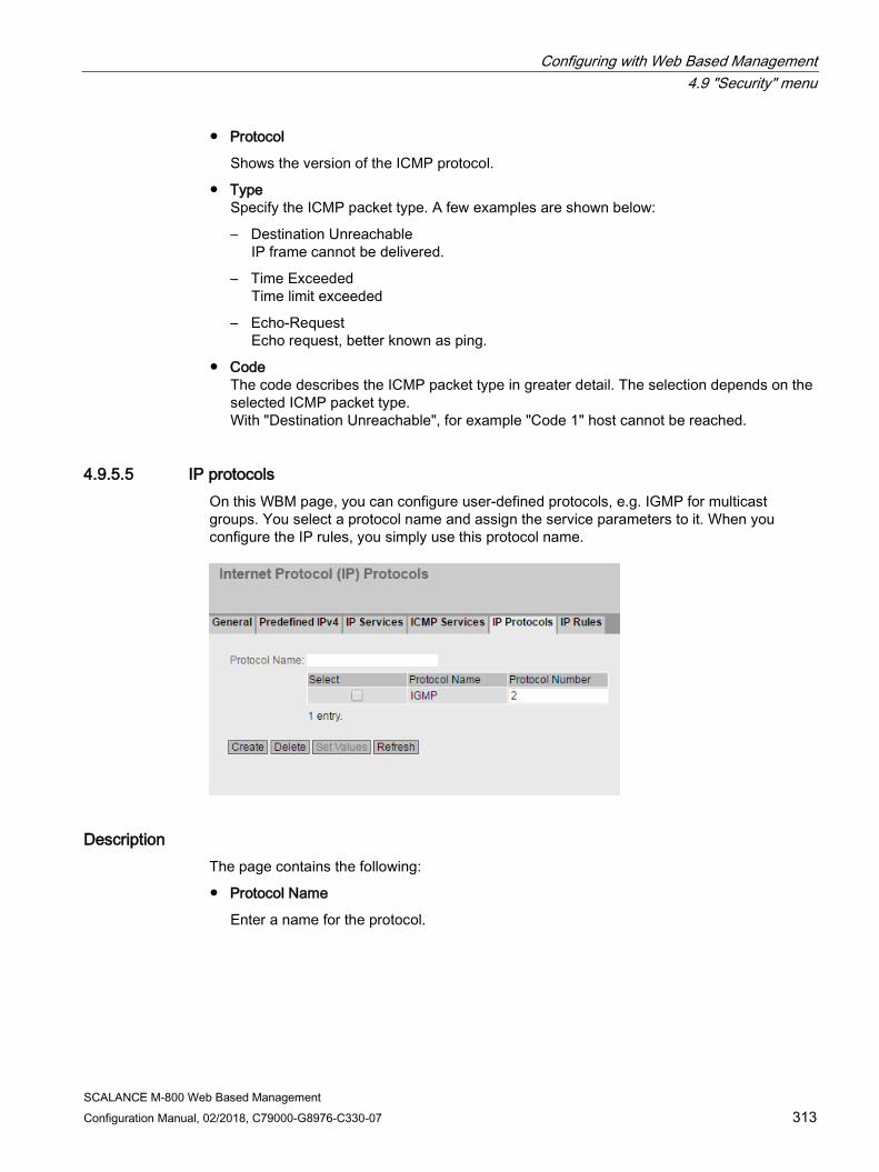
Configuring with Web Based Management 4.9 "Security" menu
SCALANCE M-800 Web Based Management Configuration Manual, 02/2018, C79000-G8976-C330-07 313
● Protocol
Shows the version of the ICMP protocol.
● Type Specify the ICMP packet type. A few examples are shown below:
– Destination Unreachable IP frame cannot be delivered.
– Time Exceeded Time limit exceeded
– Echo-Request Echo request, better known as ping.
● Code The code describes the ICMP packet type in greater detail. The selection depends on the selected ICMP packet type. With "Destination Unreachable", for example "Code 1" host cannot be reached.
4.9.5.5 IP protocols On this WBM page, you can configure user-defined protocols, e.g. IGMP for multicast groups. You select a protocol name and assign the service parameters to it. When you configure the IP rules, you simply use this protocol name.
Description The page contains the following:
● Protocol Name
Enter a name for the protocol.

Configuring with Web Based Management 4.9 "Security" menu
SCALANCE M-800 Web Based Management 314 Configuration Manual, 02/2018, C79000-G8976-C330-07
The page contains the following check boxes:
● Select
Select the check box in the row to be deleted.
● Protocol Name
Shows the protocol name.
● Protocol Number
Enter the protocol number, for example 2. You will find list of the protocol numbers on the Internet pages of iana.org
Procedure Create IGMP protocol
1. Enter IGMP in "Protocol Name".
2. Click the "Set Values" button. A new entry is generated in the table.
3. Enter "2" in "Protocol Number".
4.9.5.6 IP rules On this WBM page you specify your own IP packet filter rules for the firewall.
The IP packet filer rules set here have priority:
● over the predefined IP packet filter rules (predefined IPv4) and
● over the IP packet filter rules created automatically due to a connection configuration (SINEMA RC).

Configuring with Web Based Management 4.9 "Security" menu
SCALANCE M-800 Web Based Management Configuration Manual, 02/2018, C79000-G8976-C330-07 315
Description of the displayed boxes This table contains the following columns:
● Select Activate the check box in the row to be deleted.
● Protocol Shows the version of the IP protocol.
● Action
Select how incoming IP packets are handled:
– "Accept" - The data packets can pass through.
– "Reject" – The data packets are rejected, and the sender receives a corresponding message.
– "Drop" – The data packets are discarded without any notification to the sender.
● From / To Specify the communications direction of the IP rule.
– VLANx: VLANs with configured subnet
– Device: Device
– ppp0 or usb0 (only with M876-4): WAN interface
– SINEMA RC: Connection to SINEMA RC Server
– IPsec: Either all IPsec VPN connections (all) or a specific IPsec VPN connection
● Source (Range)
Enter the IP address or an IP range that is allowed to send IP packets.
– If the rule is intended to apply to an IP range, enter the range with start address "-" end address , for example 192.168.100.10 - 192.168.100.20.
– If the rule is intended to apply to all IP addresses , enter " 0.0.0.0/0".
● Destination (Range)
Enter the IP address or an IP range that is allowed to receive IP packets.
– If the rule is intended to apply to an IP range, enter the range with start address "-" end address , for example 192.168.100.10 - 192.168.100.20.
– If the rule is intended to apply to all IP addresses , enter " 0.0.0.0/0".
● Service Select the service or the protocol name for which this rule is valid.

Configuring with Web Based Management 4.9 "Security" menu
SCALANCE M-800 Web Based Management 316 Configuration Manual, 02/2018, C79000-G8976-C330-07
● Log Specify whether or not there should be a log entry every time the rule comes into effect and specify the severity of the event. The following settings are available:
– none The rule coming into effect is not logged.
– info / warning / critical The rule coming into effect is logged with the selected event severity. The log file is displayed in "Information" > "Log Tables" > "Firewall Log".
● Precedence Specify the precedence of the rule.
4.9.6 IPsec VPN
4.9.6.1 General On the WBM page, you configure the basic settings for VPN.
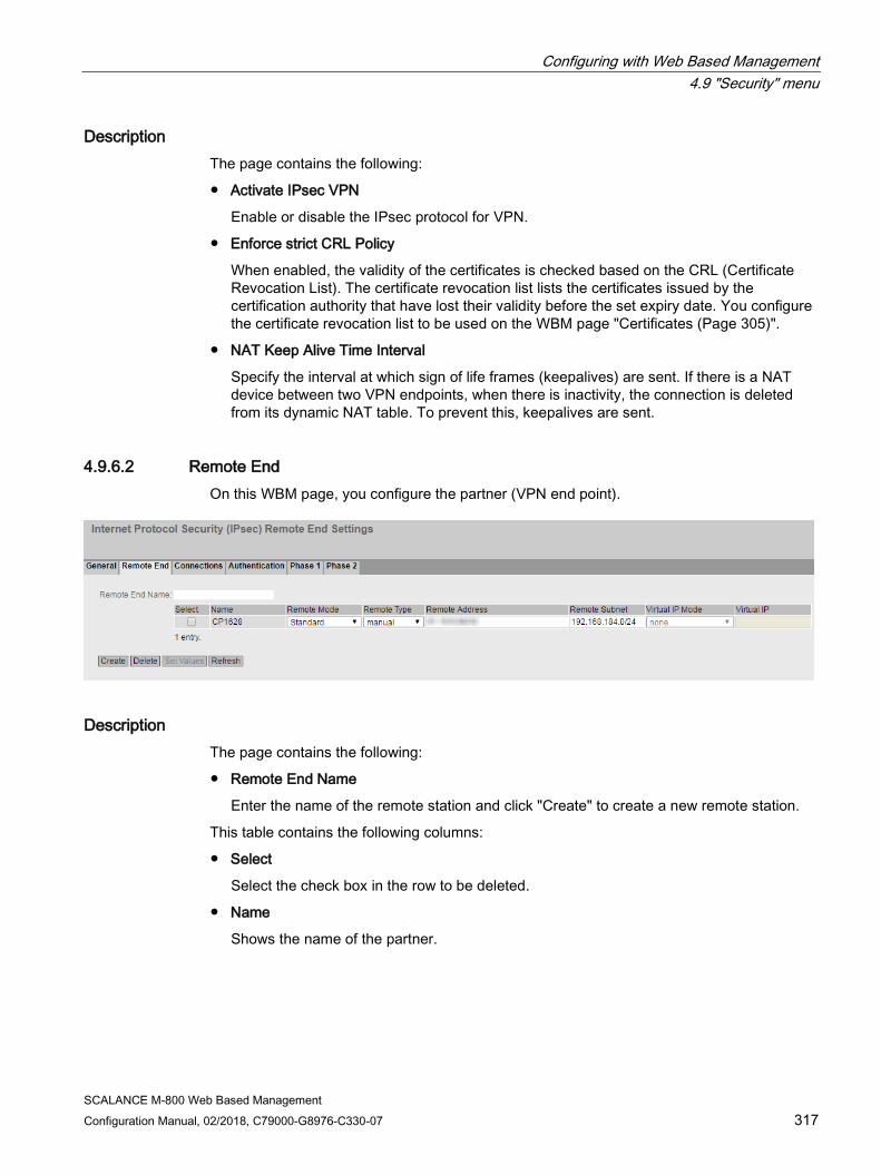
Configuring with Web Based Management 4.9 "Security" menu
SCALANCE M-800 Web Based Management Configuration Manual, 02/2018, C79000-G8976-C330-07 317
Description The page contains the following:
● Activate IPsec VPN
Enable or disable the IPsec protocol for VPN.
● Enforce strict CRL Policy
When enabled, the validity of the certificates is checked based on the CRL (Certificate Revocation List). The certificate revocation list lists the certificates issued by the certification authority that have lost their validity before the set expiry date. You configure the certificate revocation list to be used on the WBM page "Certificates (Page 305)".
● NAT Keep Alive Time Interval
Specify the interval at which sign of life frames (keepalives) are sent. If there is a NAT device between two VPN endpoints, when there is inactivity, the connection is deleted from its dynamic NAT table. To prevent this, keepalives are sent.
4.9.6.2 Remote End On this WBM page, you configure the partner (VPN end point).
Description The page contains the following:
● Remote End Name
Enter the name of the remote station and click "Create" to create a new remote station.
This table contains the following columns:
● Select
Select the check box in the row to be deleted.
● Name
Shows the name of the partner.

Configuring with Web Based Management 4.9 "Security" menu
SCALANCE M-800 Web Based Management 318 Configuration Manual, 02/2018, C79000-G8976-C330-07
● Remote Mode
Specify the role the remote stations will adopt.
– Roadwarrior The reachable remote addresses are entered. The reachable remote subnets are learned from the partner.
– Standard The reachable remote address and the reachable remote subnets are entered permanently.
● Remote Type
Specify the type of remote station address.
– Manual
The address of the partner is known. The device can either establish the VPN connection actively as a VPN client or wait passively for connection establishment by the partner.
– Any
Accepts the connection from remote stations with any IP address. The device can only wait for VPN connections but cannot establish a VPN tunnel as the active partner.
● Remote Address
Can only be edited with the remote type "Manual".
– In standard mode, enter the WAN IP address or the DDNS hostname of the partner. The network mask is always 32
– In Roadwarrior mode, you can specify either the address of the partner or enter an IP range from which connections will be accepted.
● Remote Subnet
– In standard mode, enter the remote subnet of the remote station. Use the CIDR notation.
– In Roadwarrior mode, the remote address informs the device of its reachable subnets and the device learns them.
● Virtual IP Mode
Specify whether or not the remote station is offered a virtual IP address.
The following options are available:
– user defined IPv4 The virtual IP address is from the band specified in "Virtual IP".
– None No virtual IP address. The VPN tunnel is established dynamically to the internal IP address of the remote station.
● Virtual IP Specify the subnet (CIDR) from which the remote station is offered a virtual IP address. Can only be edited if "user defined IPv4" is selected in "Virtual IP Mode".
Configuring with Web Based Management 4.9 "Security" menu
SCALANCE M-800 Web Based Management Configuration Manual, 02/2018, C79000-G8976-C330-07 319
Procedure Configure VPN standard mode
1. Enter the name of the remote station in "Remote End Name".
2. Click the "Create" button. A new entry is generated in the table.
3. For "Remote Mode", select "Standard".
4. For "Remote Type", select "manual".
5. In "Remote Address", enter the WAN IP address and in "Remote Subnet" the subnet of the remote station.
6. Click the "Set Values" button.
Configure VPN Roadwarrior mode
1. Enter the name of the remote station in "Remote End Name".
2. Click the "Create" button. A new entry is generated in the table.
3. For "Remote Mode", select "Roadwarrior".
4. For "Remote Type", select "Any".
5. In "Remote Address", enter the IP address of the remote network.
6. In "Virtual IP Mode", specify how the IP address of the VPN gateway is obtained.
7. Click the "Set Values" button.
4.9.6.3 Connections On the WBM page, you configure the basic settings for the VPN connection. With these settings, the device (local endpoint) can establish a secure VPN tunnel to the partner. You specify the security settings on the WBM page "Authentication".
Note Several IPsec VPN connections via the same VPN endpoint
If you have created IPsec VPN connections to different remote subnets via the same VPN endpoint, the first configured VPN connection (lowest index) is the main connection (parent).
Via the main connection all other IPsec VPN connections (children) are created and established. If all VPN tunnels are now established and the main (parent) connection is terminated all child connections are interrupted. After the DPD timeout has expired, all IPsec VPN connections are reestablished via the main connection.
If only one child connection is terminated, the parent connection and the other child connections are retained.
Note IPsec: Restrictions for phase 2 connections
Create a maximum of 20 phase 2 connections per phase 1 (remote endpoint).
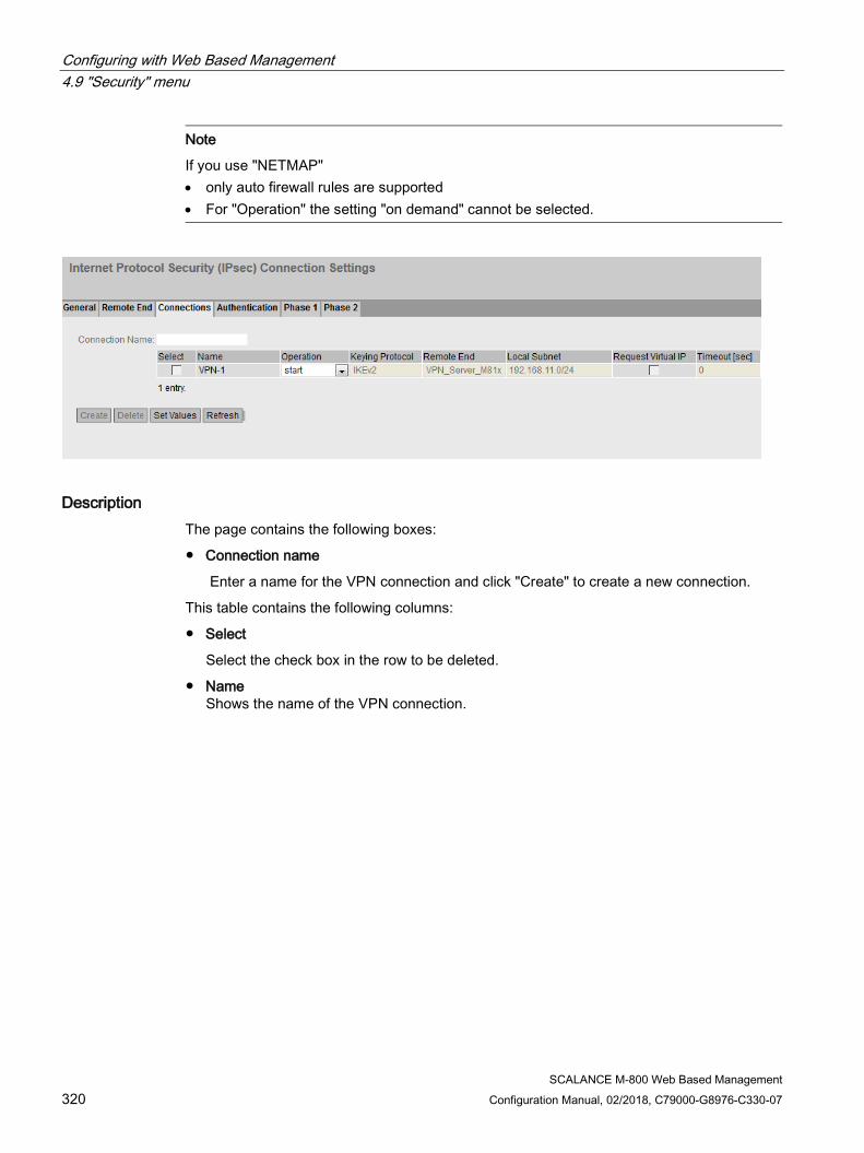
Configuring with Web Based Management 4.9 "Security" menu
SCALANCE M-800 Web Based Management 320 Configuration Manual, 02/2018, C79000-G8976-C330-07
Note
If you use "NETMAP" • only auto firewall rules are supported • For "Operation" the setting "on demand" cannot be selected.
Description The page contains the following boxes:
● Connection name
Enter a name for the VPN connection and click "Create" to create a new connection.
This table contains the following columns:
● Select
Select the check box in the row to be deleted.
● Name Shows the name of the VPN connection.
Configuring with Web Based Management 4.9 "Security" menu
SCALANCE M-800 Web Based Management Configuration Manual, 02/2018, C79000-G8976-C330-07 321
● Operation Specify who establishes the VPN connection. You will find more detailed information in "Technical basics > VPN connection establishment (Page 60)".
– Disabled
The VPN connection is disabled.
– start The device attempts to establish a VPN connection to the partner.
– wait
The device waits for the remote station to initiate the connection establishment.
– on demand
The VPN connection is established when necessary.
– start on DI
If the event "Digital In" occurs the device attempts to establish a VPN connection to the remote station.
This is on condition that the event "Digital In" is forwarded to the VPN connection. To do this in "System > Events> Configuration" activate "VPN Tunnel" for the "Digital In" event.
– wait on DI
If the event "Digital In" occurs, the device waits for the remote station to initiate connection establishment.
This is on condition that the event "Digital In" is forwarded to the VPN connection. To do this in "System > Events> Configuration" activate "VPN Tunnel" for the "Digital In" event.
– With start on SMS(M87x only) If the device receives a command SMS, the device attempts to establish a VPN connection to the remote station. This assumes that the device accepts a command SMS of the class "System" from certain senders. You configure the senders in "System > SMS > SMS Command".
– wait on SMS (M87x only) When the device receives an SMS command, the device waits until the connection establishment is initiated by the remote station. This assumes that the device accepts a command SMS of the class "System" from certain senders. You configure the senders in "System > SMS > SMS Command".
● Keying Protocol
Specify whether IKEv2 or IKEv1 will be used.
● Remote End
Select the required remote station. Only partners can be configured that have been configured on the "Remote End" WBM page.
● Local Subnet
Enter the local subnet. Use the CIDR notation. The local network can also be a single PC or another subset of the local network.
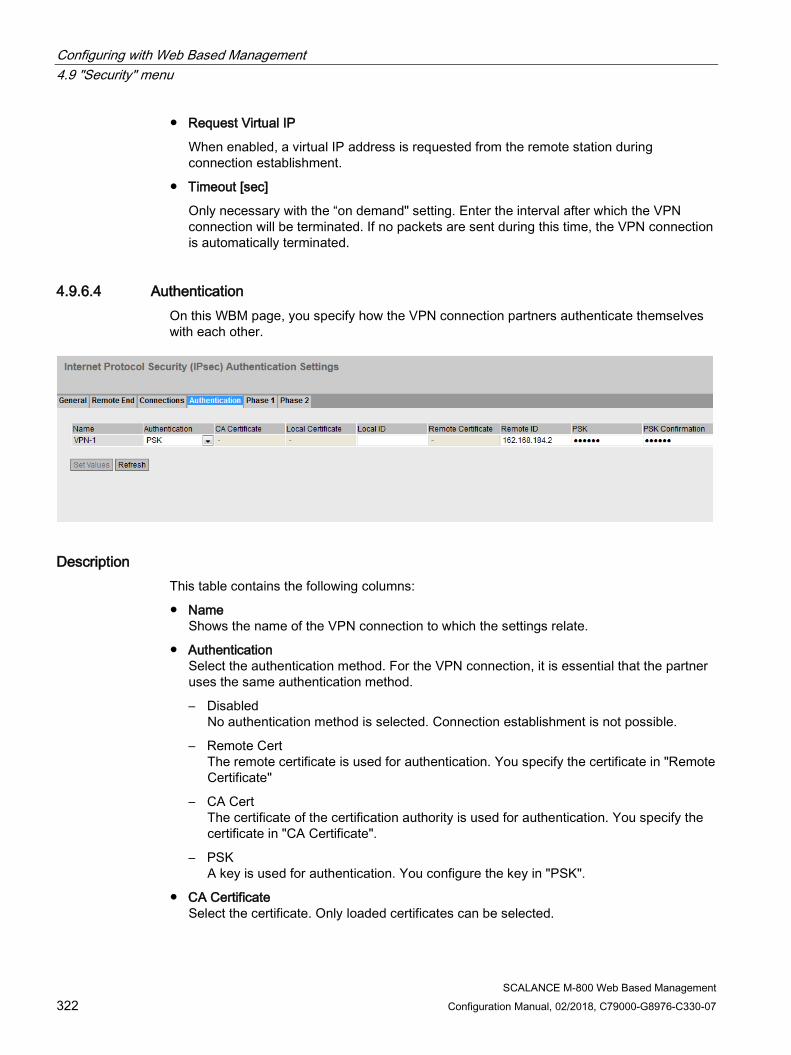
Configuring with Web Based Management 4.9 "Security" menu
SCALANCE M-800 Web Based Management 322 Configuration Manual, 02/2018, C79000-G8976-C330-07
● Request Virtual IP
When enabled, a virtual IP address is requested from the remote station during connection establishment.
● Timeout [sec]
Only necessary with the “on demand" setting. Enter the interval after which the VPN connection will be terminated. If no packets are sent during this time, the VPN connection is automatically terminated.
4.9.6.4 Authentication On this WBM page, you specify how the VPN connection partners authenticate themselves with each other.
Description This table contains the following columns:
● Name Shows the name of the VPN connection to which the settings relate.
● Authentication Select the authentication method. For the VPN connection, it is essential that the partner uses the same authentication method.
– Disabled No authentication method is selected. Connection establishment is not possible.
– Remote Cert The remote certificate is used for authentication. You specify the certificate in "Remote Certificate"
– CA Cert The certificate of the certification authority is used for authentication. You specify the certificate in "CA Certificate".
– PSK A key is used for authentication. You configure the key in "PSK".
● CA Certificate Select the certificate. Only loaded certificates can be selected.
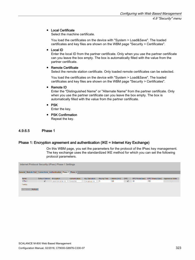
Configuring with Web Based Management 4.9 "Security" menu
SCALANCE M-800 Web Based Management Configuration Manual, 02/2018, C79000-G8976-C330-07 323
● Local Certificate Select the machine certificate.
You load the certificates on the device with "System > Load&Save". The loaded certificates and key files are shown on the WBM page "Security > Certificates".
● Local ID Enter the local ID from the partner certificate. Only when you use the partner certificate can you leave the box empty. The box is automatically filled with the value from the partner certificate.
● Remote Certificate Select the remote station certificate. Only loaded remote certificates can be selected.
You load the certificates on the device with "System > Load&Save". The loaded certificates and key files are shown on the WBM page "Security > Certificates".
● Remote ID Enter the "Distinguished Name" or "Alternate Name" from the partner certificate. Only when you use the partner certificate can you leave the box empty. The box is automatically filled with the value from the partner certificate.
● PSK Enter the key.
● PSK Confirmation Repeat the key.
4.9.6.5 Phase 1
Phase 1: Encryption agreement and authentication (IKE = Internet Key Exchange) On this WBM page, you set the parameters for the protocol of the IPsec key management. The key exchange uses the standardized IKE method for which you can set the following protocol parameters.
Configuring with Web Based Management 4.9 "Security" menu
SCALANCE M-800 Web Based Management 324 Configuration Manual, 02/2018, C79000-G8976-C330-07
Description This table contains the following columns:
● Name
Shows the name of the VPN connection to which the settings relate.
● Default Ciphers
When enabled, a preset list is transferred to the VPN connection partner during connection establishment. The list contains a combination of the three algorithms (Encryption, Authentication, Key Derivation). To establish a VPN connection, the VPN connection partner must support at least one of the combinations. The selection depends on the key exchange method. Further information can be found in the section "IPsec VPN (Page 56)"
● Encryption
For phase 1, select the required encryption algorithm. Can only be selected if "Default Ciphers" is disabled. The selection depends on the key exchange method. Further information can be found in the section "IPsec VPN (Page 56)".
Note
The AES modes CCM and GCM contain separate mechanisms for authenticating data. If you use a mode AES x CCM for "Encryption", this is also used for authentication. Then only the pseudo random function will be derived from the "Authentication" parameter. So that a VPN connection can be established, all devices need to use the same settings.
● Authentication
Specify the method for calculating the checksum. Can only be selected if "Default Ciphers" is disabled. The following methods are supported:
– MD5
– SHA1
– SHA512
– SHA256
– SHA384

Configuring with Web Based Management 4.9 "Security" menu
SCALANCE M-800 Web Based Management Configuration Manual, 02/2018, C79000-G8976-C330-07 325
● Key derivation
Select the required Diffie-Hellmann group (DH) from which a key will be generated. Can only be selected if "Default Ciphers" is disabled.
The following DH groups are supported:
– DH group 1
– DH group 2
– DH group 5
– DH group 14
– DH group 15
– DH group 16
– DH group 17
– DH group 18
● Keying Tries
Enter the number of repetitions for a failed connection establishment. If you enter the value 0, the connection establishment will be attempted endlessly.
Life Time [min]
Enter a period in minutes to specify the lifetime of the authentication. When the time has elapsed, the VPN endpoints involved must authenticate themselves with each other again and generate a new key
● DPD
When enabled DPD is used. Using DPD, it is possible to find out whether the VPN connection still exists or whether it has aborted.
Note
Sending DPD queries increases the amount of data sent and received. This can lead to increased costs
● DPD Period [sec]
Enter the period after which DPD requests are sent. These queries test whether or not the remote station is still available
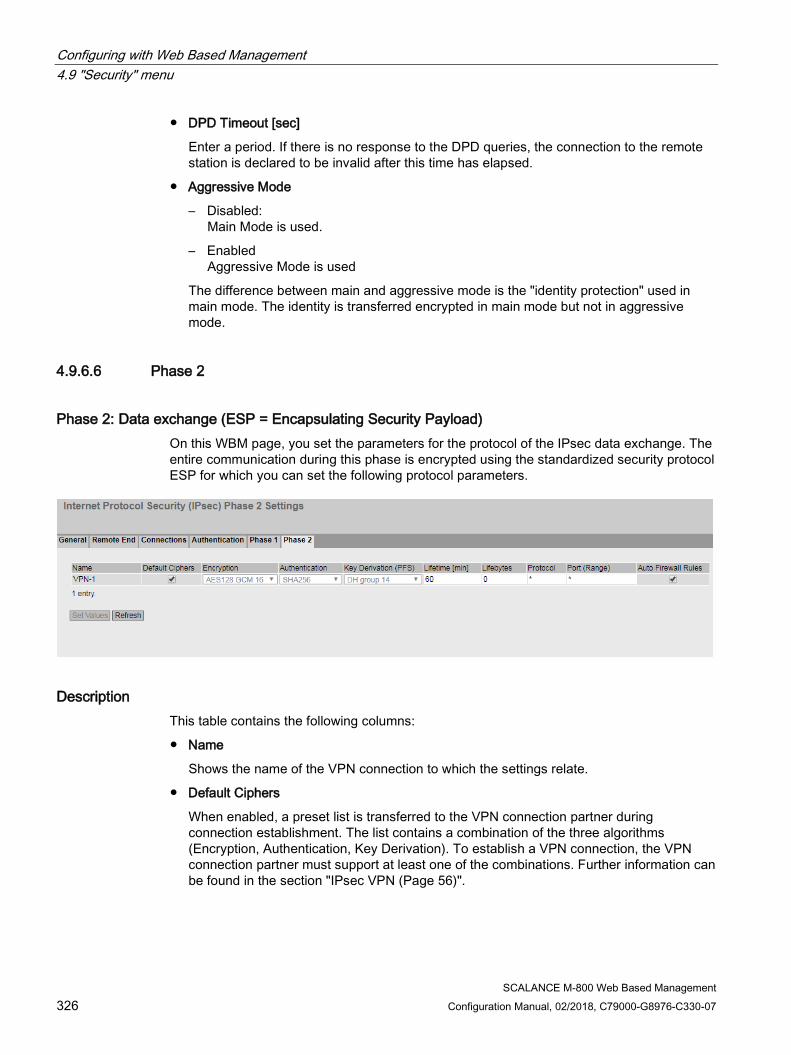
Configuring with Web Based Management 4.9 "Security" menu
SCALANCE M-800 Web Based Management 326 Configuration Manual, 02/2018, C79000-G8976-C330-07
● DPD Timeout [sec]
Enter a period. If there is no response to the DPD queries, the connection to the remote station is declared to be invalid after this time has elapsed.
● Aggressive Mode
– Disabled: Main Mode is used.
– Enabled Aggressive Mode is used
The difference between main and aggressive mode is the "identity protection" used in main mode. The identity is transferred encrypted in main mode but not in aggressive mode.
4.9.6.6 Phase 2
Phase 2: Data exchange (ESP = Encapsulating Security Payload) On this WBM page, you set the parameters for the protocol of the IPsec data exchange. The entire communication during this phase is encrypted using the standardized security protocol ESP for which you can set the following protocol parameters.
Description This table contains the following columns:
● Name
Shows the name of the VPN connection to which the settings relate.
● Default Ciphers
When enabled, a preset list is transferred to the VPN connection partner during connection establishment. The list contains a combination of the three algorithms (Encryption, Authentication, Key Derivation). To establish a VPN connection, the VPN connection partner must support at least one of the combinations. Further information can be found in the section "IPsec VPN (Page 56)".

Configuring with Web Based Management 4.9 "Security" menu
SCALANCE M-800 Web Based Management Configuration Manual, 02/2018, C79000-G8976-C330-07 327
● Encryption
For phase 2, select the required encryption algorithm. Can only be selected if "Default Ciphers" is disabled. Further information can be found in the section "IPsec VPN (Page 56)".
Note
The AES modes CCM and GCM contain separate mechanisms for authenticating data. If you use a mode AES x CCM or AES x GCM for "Encryption", this will also be used for authentication. Then only the pseudo random function will be derived from the "Authentication" parameter.
● Authentication
Specify the method for calculating the checksum. Can only be selected if "Default Ciphers" is disabled. The following methods are supported:
– MD5
– SHA1
– SHA512
– SHA256
– SHA384
● Key Derivation Select the required Diffie-Hellmann group (DH) from which a key will be generated. Can only be selected if "Default Ciphers" is disabled.
The following DH groups are supported:
– None: For phase 2, no separate keys are exchanged. This means that Perfect Forward Secrecy (PFS) is disabled.
– DH group 1
– DH group 2
– DH group 5
– DH group 14
– DH group 15
– DH group 16
– DH group 17
– DH group 18
Note
So that a VPN connection can be established, all devices need to use the same settings or provide compatible key procedures..
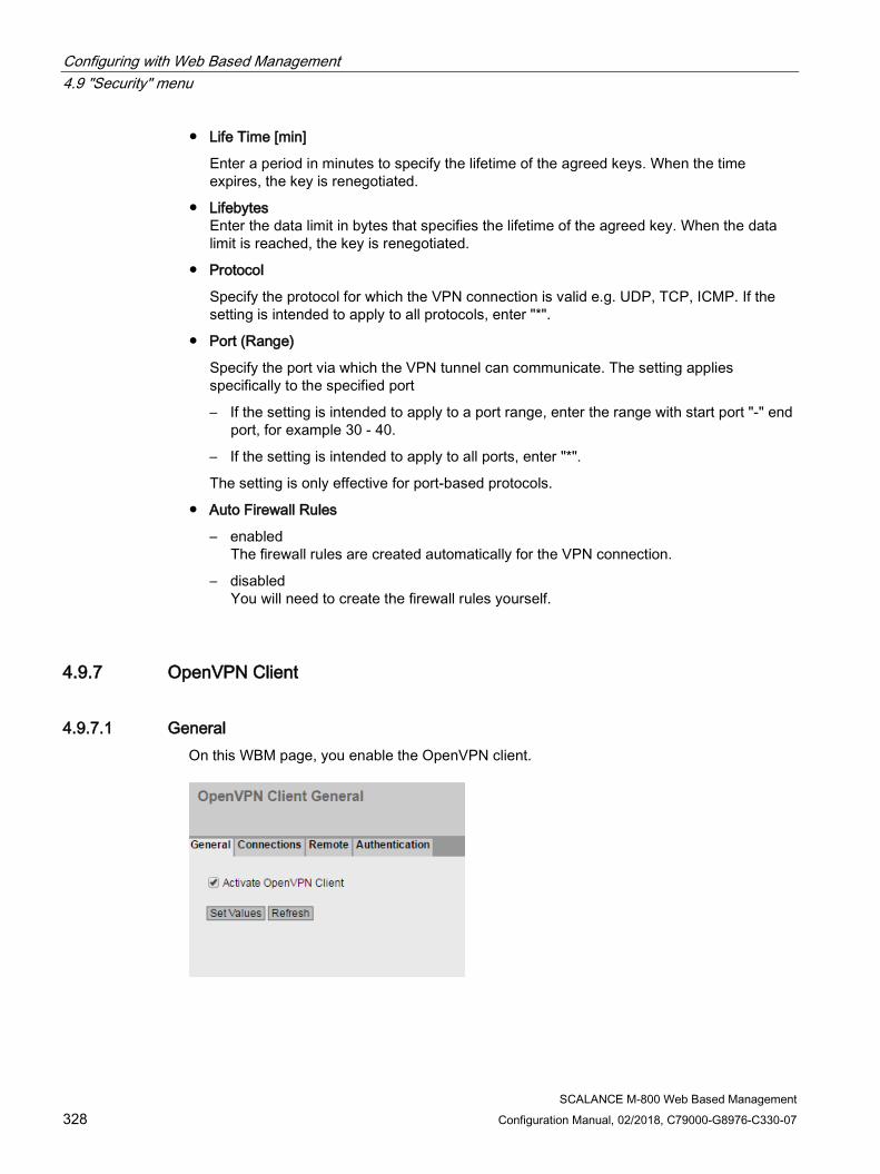
Configuring with Web Based Management 4.9 "Security" menu
SCALANCE M-800 Web Based Management 328 Configuration Manual, 02/2018, C79000-G8976-C330-07
● Life Time [min]
Enter a period in minutes to specify the lifetime of the agreed keys. When the time expires, the key is renegotiated.
● Lifebytes Enter the data limit in bytes that specifies the lifetime of the agreed key. When the data limit is reached, the key is renegotiated.
● Protocol
Specify the protocol for which the VPN connection is valid e.g. UDP, TCP, ICMP. If the setting is intended to apply to all protocols, enter "*".
● Port (Range)
Specify the port via which the VPN tunnel can communicate. The setting applies specifically to the specified port
– If the setting is intended to apply to a port range, enter the range with start port "-" end port, for example 30 - 40.
– If the setting is intended to apply to all ports, enter "*".
The setting is only effective for port-based protocols.
● Auto Firewall Rules
– enabled The firewall rules are created automatically for the VPN connection.
– disabled You will need to create the firewall rules yourself.
4.9.7 OpenVPN Client
4.9.7.1 General On this WBM page, you enable the OpenVPN client.
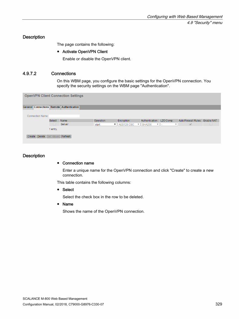
Configuring with Web Based Management 4.9 "Security" menu
SCALANCE M-800 Web Based Management Configuration Manual, 02/2018, C79000-G8976-C330-07 329
Description The page contains the following:
● Activate OpenVPN Client
Enable or disable the OpenVPN client.
4.9.7.2 Connections On this WBM page, you configure the basic settings for the OpenVPN connection. You specify the security settings on the WBM page "Authentication".
Description ● Connection name
Enter a unique name for the OpenVPN connection and click "Create" to create a new connection.
This table contains the following columns:
● Select
Select the check box in the row to be deleted.
● Name
Shows the name of the OpenVPN connection.
Configuring with Web Based Management 4.9 "Security" menu
SCALANCE M-800 Web Based Management 330 Configuration Manual, 02/2018, C79000-G8976-C330-07
● Operation
Specify how the VPN connection is established. You will find more detailed information in "Technical basics > VPN connection establishment (Page 60)".
– start
The device attempts to establish a VPN connection to the partner.
– start on DI
If the event "Digital In" occurs the device attempts to establish a VPN connection to the remote station.
This is on condition that the event "Digital In" is forwarded to the VPN connection. To do this in "System > Events> Configuration" activate "VPN Tunnel" for the "Digital In" event.
– start on SMS (only with M87x)
If the device receives a command SMS, the device attempts to establish a VPN connection to the partner. This assumes that the device accepts a command SMS of the class "System" from certain senders. You configure the senders in "System > SMS > SMS Command".
– Disabled
The VPN connection is disabled.
● Device Type
Select the required device driver.
– tun: TUN-Device The LAN Interface and the virtual network interface are located in different IP subnets. The data packets (layer 3) are routed between the interfaces.
● Encryption
Select the required encryption algorithm.
– AES-128-CBC (default)
– AES-192-CBC
– AES-256-CBC
– DES-EDE3
– BF-CBC
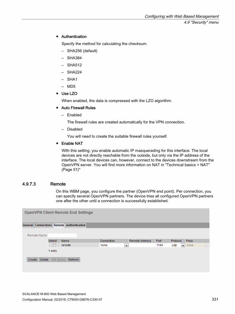
Configuring with Web Based Management 4.9 "Security" menu
SCALANCE M-800 Web Based Management Configuration Manual, 02/2018, C79000-G8976-C330-07 331
● Authentication
Specify the method for calculating the checksum.
– SHA256 (default)
– SHA384
– SHA512
– SHA224
– SHA1
– MD5
● Use LZO
When enabled, the data is compressed with the LZO algorithm.
● Auto Firewall Rules
– Enabled
The firewall rules are created automatically for the VPN connection.
– Disabled
You will need to create the suitable firewall rules yourself.
● Enable NAT
With this setting, you enable automatic IP masquerading for this interface. The local devices are not directly reachable from the outside, but only via the IP address of the interface. The local devices can, however, connect to the devices downstream from the OpenVPN server. You will find more information on NAT in "Technical basics > NAT" (Page 51)"
4.9.7.3 Remote On this WBM page, you configure the partner (OpenVPN end point). Per connection, you can specify several OpenVPN partners. The device tries all configured OpenVPN partners one after the other until a connection is successfully established.

Configuring with Web Based Management 4.9 "Security" menu
SCALANCE M-800 Web Based Management 332 Configuration Manual, 02/2018, C79000-G8976-C330-07
Description The page contains the following:
● Remote Name
Enter a name for the OpenVPN partner and click "Create" to create a new partner.
This table contains the following columns:
● Select
Select the check box in the row to be deleted.
● Name
Shows the name of the Open VPN partner.
● Connection
Select the corresponding connection. Only connections can be configured that have been configured on the "Connections" WBM page.
● Remote Address
Enter the WAN IP address or the DNS host name of the OpenVPN partner.
● Port
Specify the port via which the OpenVPN tunnel can communicate. The setting applies specifically to the specified port.
● Protocol
Specify the protocol for which the OpenVPN connection will be used.
● Proxy
Specify whether the OpenVPN tunnel to the defined OpenVPN partner is established via a proxy server. Only the proxy servers can be selected that you configured in "System > Proxy Server".
4.9.7.4 Authentication On this WBM page, you specify how the VPN connection partners authenticate themselves with each other.
Configuring with Web Based Management 4.9 "Security" menu
SCALANCE M-800 Web Based Management Configuration Manual, 02/2018, C79000-G8976-C330-07 333
Description This table contains the following columns:
● Name
Shows the name of the VPN connection to which the settings relate.
● Method
Select the authentication method. For the VPN connection, it is essential that the partner uses the same authentication method.
– Disabled
No authentication method is selected. Connection establishment is not possible.
– Certificates
Certificates are used for the authentication.
– Username/Password The user name/password are used for the authentication.
● CA Certificate
Select the certificate. Only loaded certificates can be selected.
You load the certificates on the device with "System > Load&Save". The loaded certificates and key files are shown on the WBM page "Security > Certificates".
● Machine certificate
Select the machine certificate. Only loaded certificates can be selected.
You load the certificates on the device with "System > Load&Save". The loaded certificates and key files are shown on the WBM page "Security > Certificates".
● User Name
Specify the user name.
● Password
Enter the password.
● Password Confirmation
Confirm the password.

Configuring with Web Based Management 4.9 "Security" menu
SCALANCE M-800 Web Based Management 334 Configuration Manual, 02/2018, C79000-G8976-C330-07

SCALANCE M-800 Web Based Management Configuration Manual, 02/2018, C79000-G8976-C330-07 335
Upkeep and maintenance 5 5.1 Device configuration with PRESET-PLUG
Please not the additional information and security notes in the operating instructions of your device.
NOTICE
Do not remove or insert a PLUG during operation
A PLUG may only be removed or inserted when the device is turned off.
Note Support as of V4.3
The PRESET-PLUG functionality is supported as of firmware version V4.3.
With the PRESET-PLUG, you can install the same device configuration (start configuration, user accounts, certificates) including the corresponding firmware on multiple devices.
The PRESET PLUG is write-protected.
You configure the PRESET PLUG using the Command Line Interface (CLI).
Creating a PRESET-PLUG You create the PRESET PLUG using the Command Line Interface (CLI). You can create a PRESET-PLUG from any PLUG. To do this, follow the steps outlined below:
Note Using configurations with DHCP
Create a PRESET-PLUG only from device configurations that use DHCP. Otherwise disruptions will occur in network operation due to multiple identical IP addresses.
You assign fixed IP addresses extra following the basic installation.
Requirement
● A PLUG is inserted in the device on which you want to configure the PRESET-PLUG functionality.
Procedure
1. Start the remote configuration using CLI and log on as a user with the "admin" role.
The CLI connection works either with Telnet (port 23) or SSH (port 22).
2. Change to the Global configuration mode with the command "configure terminal".

Upkeep and maintenance 5.1 Device configuration with PRESET-PLUG
SCALANCE M-800 Web Based Management 336 Configuration Manual, 02/2018, C79000-G8976-C330-07
3. You change to the PLUG configuration mode with the "plug" command.
4. Create the PRESET-PLUG with the "presetplug" command. The firmware version of the device and the current device configuration incl. user accounts and certificates are stored on the PLUG and the PLUG is then write protected.
5. Turn off the power to the device.
6. Remove the PRESET-PLUG.
7. Start the device either with a new PLUG inserted or with the internal configuration.
Procedure for installation with the aid of the PRESET-PLUG 1. Turn off the power to the device.
2. If it exists, remove the PLUG from the slot. You will find further information on this in the operating instructions of your device.
3. Insert the PRESET-PLUG correctly oriented into the slot. The PRESET-PLUG is correctly inserted when it is completely inside the device and does not jut out of the slot.
4. Turn on the power to the device again. If there is a different firmware version on the device to be installed compared with that on the PRESET-PLUG, an upgrade/downgrade of the firmware is performed. You can recognize this by the red F-LED flashing (flashing interval: 2 sec on/0.2 sec off). Afterwards the device is restarted and the device configuration incl. users and certificates on the PRESET-PLUG is transferred to the device.
5. Wait until the device has fully started up. (the red F-LED is off)
6. Turn off the power to the device after the installation.
7. Remove the PRESET-PLUG.
8. Start the device either with a new PLUG inserted or with the internal configuration.
Note
KEY-PLUG
If you have created the PRESET-PLUG from a KEY-PLUG, for operation with this configuration, you require an inserted KEY-PLUG.
IN this case before recommissioning the device you need to insert the relevant KEY-PLUG.
Upkeep and maintenance 5.1 Device configuration with PRESET-PLUG
SCALANCE M-800 Web Based Management Configuration Manual, 02/2018, C79000-G8976-C330-07 337
Note Restore factory defaults and restart with a PRESET PLUG inserted
If you reset a device to the factory defaults, when the device restarts an inserted PRESET PLUG is formatted and the PRESET PLUG functionality is lost. You then need to create a new PRESET PLUG. The keys stored on the KEY-PLUG for releasing functions are retained.
We recommend that you remove the PRESET PLUG before you reset the device to the factory settings.
Formatting a PRESET-PLUG (resetting the preset function) You format the PRESET PLUG using the Command Line Interface (CLI) to reset the preset function. To do this, follow the steps outlined below:
1. Start the remote configuration using Telnet (CLI) and log on with a user with the "admin" role.
2. Change to the Global configuration mode with the command "configure terminal".
3. You change to the PLUG configuration mode with the "plug" command.
4. Enter the command "factoryclean". The PRESET-PLUG is formatted and the preset function is reset.
5. Write the current configuration of the device with the "write" command.
Requirement ● The device has an IP address.
● The user is logged in with administrator rights.
Firmware update using HTTP 1. Click "System" > "Load&Save" in the navigation area. Click the "HTTP" tab.
2. Click the "Loading" button next to "Firmware".
3. Go to the storage location of the firmware file.
4. Click the "Open" button in the dialog.
Firmware update via TFTP 1. Click "System > Load&Save" in the navigation area. Click the "TFTP" tab.
2. Enter the IP address of the TFTP server in the "TFTP Server Address" input box.
3. Enter the port of the TFTP server in the "TFTP Server Port" input box.
4. Click the "Load file" button in the "Firmware" table row.

Upkeep and maintenance 5.1 Device configuration with PRESET-PLUG
SCALANCE M-800 Web Based Management 338 Configuration Manual, 02/2018, C79000-G8976-C330-07
5. Go to the storage location of the firmware file.
6. Click the "Open" button in the dialog. The file is uploaded.
Firmware update via SFTP 1. Click "System > Load&Save" in the navigation area. Click the "SFTP" tab.
2. Enter the IP address of the SFTP server in the "SFTP Server Address" input box.
3. Enter the port of the SFTP server in the "SFTP Server Port" input box.
4. Enter the user and the password for access to the SFTP server.
5. Click the "Load file" button in the "Firmware" table row.
6. Go to the storage location of the firmware file.
7. Click the "Open" button in the dialog. The file is uploaded.
Result When the firmware is successfully loaded a dialog is displayed. Confirm the dialog with "OK". The device is restarted.
In "Information" > "Versions" there is the additional entry "Firmware_Running". Firmware_Running shows the version of the current firmware. Firmware shows the firmware version stored after loading the firmware.
Upkeep and maintenance 5.2 Firmware update via WBM and CLI not possible
SCALANCE M-800 Web Based Management Configuration Manual, 02/2018, C79000-G8976-C330-07 339
5.2 Firmware update via WBM and CLI not possible
Cause If there is a power failure during the firmware update, it is possible that the device is no longer accessible using WBM and CLI.
Requirement ● The PC is connected to the device via the interface.
● A TFTP client is installed on the PC and the firmware file exists.
Solution You can then also transfer firmware to the device using TFTP. Follow the steps below to load new firmware using TFTP:
1. Now press the SET button.
2. Hold down the button until the red fault LED (F) starts to flash after approximately 3 seconds.
Note
If you hold down the SET button for approximately 10 seconds, the device is reset to its factory settings and can be reached with the IP address 192.168.1.1.
3. Now release the button. The bootloader waits in this state for new firmware file that you can download by TFTP.
Note
If you want to exit the boot loader without making changes, press the SET button briefly. The device restarts with the loaded configuration.
4. Connect a PC to the device over the Ethernet interface.
5. Open a DOS box and change to the directory where the new firmware file is located and then execute the command "tftp -i <ip address> PUT <firmware>". As an alternative, you can use a different TFTP client.
If you are not sure that the IP address is correct, you can check this, for example with the Primary Setup Tool.
Note
Using TFTP
If you want to access TFTP in Windows 7, make sure that the corresponding Windows function is enabled in the operating system.

Upkeep and maintenance 5.3 Restoring the factory settings
SCALANCE M-800 Web Based Management 340 Configuration Manual, 02/2018, C79000-G8976-C330-07
Result The firmware is transferred to the device.
Note
Please note that the transfer of the firmware can take several minutes. During the transmission, the red error LED (F) flashes.
Once the firmware has been transferred completely to the device, the device is restarted automatically.
5.3 Restoring the factory settings
NOTICE
Previous settings
If you reset, all the settings you have made will be overwritten by factory defaults.
NOTICE
Inadvertent reset
An inadvertent reset can cause disturbances and failures in a configured network with further consequences.
With the reset button When pressing the button, remember the information in the section "Reset button" in the operating instructions.
Follow the steps below to reset the device parameters to the factory settings:
1. Turn off the power to the device.
2. Now press the Reset button and reconnect the power to the device while holding down the button.
3. Hold down the button until the red fault LED (F) stops flashing after approximately 10 seconds and is permanently lit.
4. Now release the button and wait until the fault LED (F) goes off again.
5. The device then starts automatically with the factory settings.
Upkeep and maintenance 5.3 Restoring the factory settings
SCALANCE M-800 Web Based Management Configuration Manual, 02/2018, C79000-G8976-C330-07 341
Via the configuration You will find detailed information on resetting the device parameters using the WBM and CLI in the configuration manuals:
● Web Based Management, section "Restart"
● Command Line Interface, section "Reset and Defaults"

Upkeep and maintenance 5.3 Restoring the factory settings
SCALANCE M-800 Web Based Management 342 Configuration Manual, 02/2018, C79000-G8976-C330-07

SCALANCE M-800 Web Based Management Configuration Manual, 02/2018, C79000-G8976-C330-07 343
Appendix A A A.1 Command SMS message
With a command SMS message, you can send commands to the device. You specify from whom a command SMS will be accepted in "System > SMS > Command SMS (Page 210)".
Format of the command SMS message The command SMS message has the following format.
● Class command action parameter
Requirement for reply SMS (STATUS) ● A phone number is stored in "System > SMS > Event SMS".
Supported commands Class Command Action Parameter SYS System com-mands
DI STATUS Pin number 1 A reply SMS message with the status of the digital input is sent.
DO STATUS Pin number 1 A reply SMS message with the status of the digital output is sent.
LOW The digital output is opened. HIGH The digital output is closed.
IPSEC STATUS Name of the IPsec VPN connection Security > IPsec VPN> Connec-tions (Page 319) With '*' IPsec connections are established that use "start on SMS" or "wait on SMS" for "Operation".
A reply SMS message with the status of the IPsec VPN tunnel is sent.
UP The IPsec VPN tunnel is being established. DOWN An existing IPsec VPN tunnel is terminated.
OVPN STATUS Name of the OpenVPN connection Security > OpenVPN> Connections (Page 329) With '*' OpenVPN connections are established that use "start on SMS" for "Operation".
A reply SMS message with the status of the OpenVPN tunnel is sent.
UP The OpenVPN tunnel is being established. DOWN An existing OpenVPN tunnel is terminated.
SRC STATUS Address of the SINEMA RC Server WAN IP address or the host name SINEMA RC (Page 130)
A reply SMS message with the status of the SINEMA RC connection is sent.
UP The connection to SINEMA RC Server is being established.
DOWN The existing connection to SINEMA RC Server is being terminated.

Appendix A A.1 Command SMS message
SCALANCE M-800 Web Based Management 344 Configuration Manual, 02/2018, C79000-G8976-C330-07
Class Command Action Parameter RLY SMS relay command
Name of the relay connec-tion Sytem > SMS > SMS Relay (Incoming) (Page 213)
- Text
The text from the SMS message is forward-ed to the recipient. The following characters are permitted in the text: • 0123456789 • A...Z a...z • Space • ! " % & / ( ) = ? * + < > ' , . -
Examples Wake-up SMS
SYS SRC UP 192.168.20.200
SMS message to an application in the LAN
RLY conn2 my SMS text
The text "my SMS Text" is forwarded to the application specified in the relay connection "conn2". The text is forwarded as the following frame: user#password#105#01;0049xxxxxxxxx;my SMS text:
SCALANCE M-800 Web Based Management Configuration Manual, 02/2018, C79000-G8976-C330-07 345
Index
A Address of the gateway, 38 Aging
Dynamic MAC Aging, 260 Alarm events, 170 Authentication, 179 Available system functions, 32
B Basic Wizard
Starting, 79 Bridge, 133, 262
Bridge priority, 133, 262 Root bridge, 133, 262
Bridge Max Age, 134, 263 Bridge Max Hop Count, 134 button, 192
C CA certificate, 55 Certificates, 306 Configuration manuals, 341 Configuration mode, 148 CoS (Class of Service), 41 C-PLUG, 34
Formatting, 200 Saving the configuration, 200
D DCP server, 147 Dead peer detection, 59 Device
Basic Wizard, 81 System, 149
Device certificate, 55 DHCP
Client, 220 DSL
Overview, 123
E E-Mail function, 170
Alarm events, 170 Line monitoring, 170
Error status, 115
F Factory defaults, 340 Factory setting, 340 Fault monitoring
Connection status change, 195 SIM card, 197
Forward Delay, 134, 263
G Geographic coordinates, 150 Glossary, 6 Groups, 296
H Hardware Revision, 107 Hello time, 134, 263
I ICMP, 45 Information
ARP table, 108 DSL, 123 Groups, 143 Hardware, 105 IPsec VPN, 129 LLDP, 118 Log table, 109, 113 Mobile, 120 OpenVPN client, 132 Role, 142 Security, 138, 141 Security log, 111 SHDSL, 127 SINEMA RC, 130
Index
SCALANCE M-800 Web Based Management 346 Configuration Manual, 02/2018, C79000-G8976-C330-07
SNMP, 117, 117 Software, 105 Spanning tree, 135 Start page, 100 Versions, 106
IP address Basic Wizard, 80 Configuration, 274
IPsec method, 56 IPsec VPN
NETMAP, 52 Source NAT, 52
IPv4 Notation, 37 VRRPv3, 68
IPv4 address, 37 IPv4 routing
Routing table, 119
K KEY-PLUG, 34, 201, 201
Formatting, 200
L Layer 2, 254 Layer 3, 201, 201 Line monitoring, 170 LLDP, 118, 267 Location, 150 Log table
Event log, 109 Firewall log, 113 Security log, 111
Logout Automatic, 191
M Maintenance data, 107 Manufacturer, 107 Manufacturer ID, 107 Mobile
Information, 120
N NAPT
Configuring, 276
NAT 1-to-1 NAT, 281 Configuring, 276 Masquerading, 51 NAPT, 51 NAT traversal, 58 NETMAP, 52 Source NAT, 52
NAT traversal, 58 NTP
Client, 186 Server, 190
O Operator
Interfaces, 241 Order ID, 107
P Password, 291, 297 Ping, 203 PLUG, 201, 201
C-PLUG, (C-PLUG) point-to-point, 67 Port
Port configuration, 235
Q QoS Trust, 41
R RADIUS, 300 Range of values for IPv4 address, 37 Redundant networks, 133, 262 Requirement
ADSL connection, 28 Antenna, 26 Power supply, 26, 27, 28 SHDSL connection, 28 SIM card, 27
Reset, 152 RESET button, 192 Reset device, 340, 340 Restart, 152 Restore Factory Defaults, 340 Roles, 294

Index
SCALANCE M-800 Web Based Management Configuration Manual, 02/2018, C79000-G8976-C330-07 347
Root Max Age, 134, 263 Routing, 269
ICMP, 45 IPv4 routing table, 119 Static routes, 269
RSTP, 261
S Security settings, 175 SELECT/SET button, 192 Serial number, 107 Server certificate, 55 Service & Support, 5 SFTP
Load/save, 161 SHA algorithm, 176 SHDSL
Interface, 85, 248 Overview, 127, 247
Signal recorder, 123 SIM
Basic Wizard, 87 Interfaces, 239
SIMATIC NET glossary, 6 SMS
receiving, 213 sending, 212
SMTP Client, 146
SNAT Configuring, 279
SNMP, 42, 147, 172, 175 Groups, 175 Overview, 117 SNMPv1, 42 SNMPv2c, 42 SNMPv3, 42 Trap, 174 Users, 178
Software version, 107 Source NAT
Masquerading, 51 Spanning tree, 261
Information, 135 Spanning Tree
Rapid Spanning Tree, 67 SSH
Server, 146 Standard mode, 56 Start page, 100 Stateful inspection firewall, 49
Subnet Configuration, 274 Overview, 271
Subnet mask, 37 Syslog, 193
Client, 146 System
Configuration, 145 Device, 149 General information, 149 Load and Save via HTTP, 155
System event log Agent, 193
System events Configuration, 166 Severity filter, 169
T Telnet
Server, 146 TFTP
Load/save, 158 Time
Time zone, 188 UTC time, 188
Time of day Manual setting, 92, 181 NTP Client, 93 SIMATIC Time Client, 189 SNTP (Simple Network Time Protocol), 183 System time, 92, 181 Time zone, 185 Time-of-day synchronization, 183 UTC time, 185
Time setting, 147 Training, 5
U User Groups, 296
V VLAN, 39
Port VID, 259 Priority, 258 Tag, 258 VLAN ID, 41 VLAN tag, 40
Index
SCALANCE M-800 Web Based Management 348 Configuration Manual, 02/2018, C79000-G8976-C330-07
VPN connection Status, 129 Status OpenVPN client, 132
VRRP VRRP addresses overview (IPv4), 287 VRRPv3 Addresses Configuration (IPv4), 288 VRRPv3 Configuration (IPv4), 286 VRRPv3 routers (IPv4), 282
VRRPv3 Backup router, 68 Interface Tracking, 289 Master router, 68 Virtual router, 68 VRRPv3 router, 68 VRRPv3 Statistics, 143
W Web Based Management, 75
Requirement, 75
Related Documents