© 2020 Alamo Group Inc. Published 09/20 Part No. 50079152 OPERATOR’S MANUAL BUSH HOG ® 2501 Griffin Ave. Selma, AL 36703 334-874-2700 www.bushhog.com This Operator's Manual is an integral part of the safe operation of this machine and must be maintained with the unit at all times. READ, UNDERSTAND, and FOLLOW the Safety and Operation Instructions contained in this manual before operating the equipment. C01- Cover SBPT60, SBPT68 SBPT78, SBPT87 & SBPT97 PULL TYPE SNOW BLOWER

Welcome message from author
This document is posted to help you gain knowledge. Please leave a comment to let me know what you think about it! Share it to your friends and learn new things together.
Transcript
© 2020AlamoGroup Inc.
Published 09/20 Part No. 50079152
OPERATOR’S MANUAL
BUSHHOG®
2501 GriffinAve.Selma,AL36703334-874-2700www.bushhog.com
This Operator's Manual is an integral part of the safe operation of this machine and mustbe maintained with the unit at all times. READ, UNDERSTAND, and FOLLOW the Safetyand Operation Instructions contained in this manual before operating the equipment. C01-Cover
SBPT60, SBPT68SBPT78, SBPT87
& SBPT97PULL TYPE SNOW BLOWER

Notes
REV:3009202

!CAUTIONOperational Hazard
Personal Protection Equipment (PPE) is required when operating or maintaining this machine.
!CAUTIONOperational Hazard
Tractor PTO must operate at 540 RPM only. Exceeding the power unit design speed of 540 RPM will result in operator injury or damage to the machine.
Table of Contents
Warranty . . . . . . . . . . . . . . . . . . . . . . . . . . . . . . . . . . . . . . . . . . . . . . . . . . . . . . . . . . . . . . . . . . . . . . . . . . . . . .4DEALER to CUSTOMER Pre-Delivery/ Operation Instructions . . . . . . . . . . . . . . . . . . . . . . . . . . . . . . . . . . . .5P65 Warning . . . . . . . . . . . . . . . . . . . . . . . . . . . . . . . . . . . . . . . . . . . . . . . . . . . . . . . . . . . . . . . . . . . . . . . . . . .5Serial Number Location . . . . . . . . . . . . . . . . . . . . . . . . . . . . . . . . . . . . . . . . . . . . . . . . . . . . . . . . . . . . . . . . . .6General Information . . . . . . . . . . . . . . . . . . . . . . . . . . . . . . . . . . . . . . . . . . . . . . . . . . . . . . . . . . . . . . . . . . . . .6Intended Use . . . . . . . . . . . . . . . . . . . . . . . . . . . . . . . . . . . . . . . . . . . . . . . . . . . . . . . . . . . . . . . . . . . . . . . . . .6Operator Orientation . . . . . . . . . . . . . . . . . . . . . . . . . . . . . . . . . . . . . . . . . . . . . . . . . . . . . . . . . . . . . . . . . . . . .6Safety . . . . . . . . . . . . . . . . . . . . . . . . . . . . . . . . . . . . . . . . . . . . . . . . . . . . . . . . . . . . . . . . . . . . . . . . . . . . . . . .7
Safety Messages . . . . . . . . . . . . . . . . . . . . . . . . . . . . . . . . . . . . . . . . . . . . . . . . . . . . . . . . . . . . . . . . . . . . . . . . . . . . . 7Accident Prevention . . . . . . . . . . . . . . . . . . . . . . . . . . . . . . . . . . . . . . . . . . . . . . . . . . . . . . . . . . . . . . . . . . . . . . . . . . . 8
Safety Guidelines . . . . . . . . . . . . . . . . . . . . . . . . . . . . . . . . . . . . . . . . . . . . . . . . . . . . . . . . . . . . . . . . . . . . . . .9Safety Training . . . . . . . . . . . . . . . . . . . . . . . . . . . . . . . . . . . . . . . . . . . . . . . . . . . . . . . . . . . . . . . . . . . . . . . . . . . . . . . 9Preparation . . . . . . . . . . . . . . . . . . . . . . . . . . . . . . . . . . . . . . . . . . . . . . . . . . . . . . . . . . . . . . . . . . . . . . . . . . . . . . . . . 10Storage Safety . . . . . . . . . . . . . . . . . . . . . . . . . . . . . . . . . . . . . . . . . . . . . . . . . . . . . . . . . . . . . . . . . . . . . . . . . . . . . . 10Operation Safety . . . . . . . . . . . . . . . . . . . . . . . . . . . . . . . . . . . . . . . . . . . . . . . . . . . . . . . . . . . . . . . . . . . . . . . . . . . . . 10Safe Work . . . . . . . . . . . . . . . . . . . . . . . . . . . . . . . . . . . . . . . . . . . . . . . . . . . . . . . . . . . . . . . . . . . . . . . . . . . . . . . . . . .11Maintenance Safety . . . . . . . . . . . . . . . . . . . . . . . . . . . . . . . . . . . . . . . . . . . . . . . . . . . . . . . . . . . . . . . . . . . . . . . . . . .11Hydraulic Safety . . . . . . . . . . . . . . . . . . . . . . . . . . . . . . . . . . . . . . . . . . . . . . . . . . . . . . . . . . . . . . . . . . . . . . . . . . . . . .11
Bush Hog Snowblower Decal Location . . . . . . . . . . . . . . . . . . . . . . . . . . . . . . . . . . . . . . . . . . . . . . . . . . . . .12Specifications . . . . . . . . . . . . . . . . . . . . . . . . . . . . . . . . . . . . . . . . . . . . . . . . . . . . . . . . . . . . . . . . . . . . . . . . .13Sign Off Form . . . . . . . . . . . . . . . . . . . . . . . . . . . . . . . . . . . . . . . . . . . . . . . . . . . . . . . . . . . . . . . . . . . . . . . . .14Bush Hog Snowblower Assembly Instructions . . . . . . . . . . . . . . . . . . . . . . . . . . . . . . . . . . . . . . . . . . . . . . .15
Upon Receiving the Bush Hog Snowblower . . . . . . . . . . . . . . . . . . . . . . . . . . . . . . . . . . . . . . . . . . . . . . . . . . . . . . . . 15Hand Crank Installation . . . . . . . . . . . . . . . . . . . . . . . . . . . . . . . . . . . . . . . . . . . . . . . . . . . . . . . . . . . . . . . . . . . . . . . . 16Optional Hydraulic Rotator Installation . . . . . . . . . . . . . . . . . . . . . . . . . . . . . . . . . . . . . . . . . . . . . . . . . . . . . . . . . . . . 17Installing the Hydraulic Chute Rotator Safety Shield with Hose Guide . . . . . . . . . . . . . . . . . . . . . . . . . . . . . . . . . . . 18Chute Stop . . . . . . . . . . . . . . . . . . . . . . . . . . . . . . . . . . . . . . . . . . . . . . . . . . . . . . . . . . . . . . . . . . . . . . . . . . . . . . . . . 20Sizing PTO Drive-line . . . . . . . . . . . . . . . . . . . . . . . . . . . . . . . . . . . . . . . . . . . . . . . . . . . . . . . . . . . . . . . . . . . . . . . . . 21PTO Installation Instructions for Snowblower . . . . . . . . . . . . . . . . . . . . . . . . . . . . . . . . . . . . . . . . . . . . . . . . . . . . . . . 22
Bush Hog Pull Type Snowblower Setup . . . . . . . . . . . . . . . . . . . . . . . . . . . . . . . . . . . . . . . . . . . . . . . . . . . . .25Operating the Bush Hog Pull Type Snowblower . . . . . . . . . . . . . . . . . . . . . . . . . . . . . . . . . . . . . . . . . . . . . . .26Bush Hog Pull Type Snowblower Maintenance . . . . . . . . . . . . . . . . . . . . . . . . . . . . . . . . . . . . . . . . . . . . . . .27
Maintenance . . . . . . . . . . . . . . . . . . . . . . . . . . . . . . . . . . . . . . . . . . . . . . . . . . . . . . . . . . . . . . . . . . . . . . . . . . . . . . . . 27Lubrication . . . . . . . . . . . . . . . . . . . . . . . . . . . . . . . . . . . . . . . . . . . . . . . . . . . . . . . . . . . . . . . . . . . . . . . . . . . . . . . . . 27Effective PTO Drive Shaft Maintenance . . . . . . . . . . . . . . . . . . . . . . . . . . . . . . . . . . . . . . . . . . . . . . . . . . . . . . . . . . . 28
Bolt Torque . . . . . . . . . . . . . . . . . . . . . . . . . . . . . . . . . . . . . . . . . . . . . . . . . . . . . . . . . . . . . . . . . . . . . . . . . . .31
3

Warranty
WarrantyTwo Year Limited Consumer Warranty
Five Year Limited Consumer Warranty on Gearboxes90 Day Limited Commercial Warranty including Gearboxes
Commercial includes rental and industrial applications.Warranty begins at the time of customer delivery and is activated upon warranty registration receipt
at Bush Hog Inc. Warranty coverage is null and void unless the Warranty Registration form has been completed
in full and is on file at Bush Hog Inc. Keep your registration copy in a safe place, it is required as proof of warranty activation.
This new and unused product is warranted by Bush Hog Inc. to be free from defects in material and workmanship under normal use and regular service as described in the owner’s manual, for a consumer period of 2 years and 5 years for gearboxes, from the date of delivery, and commercial period of 90 days, including gearboxes, from the date of delivery. Warranty is limited to the replacement of parts and / or repair of the product.
If issues develop within the warranty period with the product, contact the local dealer from which you purchased the unit. Only Bush Hog Inc. authorized dealers may make repairs to the product or affect the replacement of defective parts, unless otherwise ap-proved by Bush Hog Inc. Repairs / replacement will be done at no charge within a reasonable time after the receipt of the product.
This warranty does not cover the following items:
1. Normal replacement of service items.2. Normal maintenance or adjustments.3. Machines or parts lost or damaged during shipment,4. Accessory items / parts not supplied by Bush Hog Inc.5. Damages resulting from:
misuse, negligence, accident, theft or fire use of improper or insufficient fuel, fluids or lubricants use of after market parts or accessories, unless approved by Bush Hog modifications, alteration, tampering or improper repair any device or accessories installed by other than an authorized dealer.
6. Tires are covered by the manufacturer of the tire and the warranty period specified by that manufacturer. Please contact the tire manufacturer for warranty on these items.
Bush Hog Inc. shall not, in any event, be liable for any losses, damages or costs; to include profits, travel, transportation, pick up, delivery, towing cost, tow vehicle, loss of use, whether special, incidental, consequential or otherwise, in any way. Unit or parts are returned at the customer’s expense.
Include a copy of your completed Warranty Registration form with any claim as proof of warranty activation.
There are no warranties, expressed or implied, other than those specified herein. No agent, employee or other person has any authority to vary any of the foregoing provisions.
Warranty coverage is null and void unless the Warranty Registration form has been completed in full and is on file at Bush Hog Inc.. Warranty begins at the time of customer delivery and is activated upon Warranty Registration receipt at Bush Hog Inc.
Bush Hog Inc. � 2501 Griffin Ave.Selma, AL 36703 � Office: (334) 874-3159
180118
4
P65 Warning
Dealer: inform the Purchaser of this product of the Warranty terms, provisions, and procedures that are applicable. Submit warranty information to Bush HogDealer should inform Purchaser to review the contents of this Operator’s Manual including safety equipment, safe operation, and maintenance, to review the Safety Signs on the blower (and tractor if possible), and of Purchaser’s responsibility to train his/her operator’s in safe operation procedures.• MACHINE: explain that Deflectors, Chain Guards, or Safety Devices must be installed and maintained in good repair.• DRIVE-LINES: make certain that all drive-line, gearbox, and other shields are in good repair and fastened securely in place to prevent injuries from entanglement or thrown objects.• HYDRAULIC COMPONENTS: explain the necessity of using clean hydraulic oil, changing filters as instructed, stopping leaks, damage caused by operating with over-heated oil, caring for hoses, using hoses of proper rating, maintaining the specified operating pressure and the potential hazard of hydraulic oil penetrating the skin.• LIFTING: explain that there is an increased possibility of thrown objects when the blower is lifted off the ground while in operation and that operator is responsible to watch out for persons in the area. Explain that the lifted blower can contact overhead obstructions with damage to cables and telephone lines and possible injury and that the chute can contact power lines with resulting electrocution, injury or death and that operator is responsible for keeping clear of such hazards.
DEALER to CUSTOMER Pre-Delivery/ Operation InstructionsDealer: please inspect the machine before delivery to the customer:• Check fan and auger clearance and they turn freely
• Discharge and deflector move freely
• All fasteners are tight
• Grease zerks and pivot points lubricated
• Check that lock pins align and move freely
• Operating and safety instructions reviewed
• All safety decals installed
• Guards and shields installed and secured
• SMV sign installed (if required)
• Retainer installed through hitch points
Cancer and Reproductive Harm www.P65Warnings.ca.gov
Cancer and Reproductive Harmwww.P65 Warnings.ca.gov
D960
WARNING
5
THIRD ANGLE PROJECTION
5 4 3 1
Folder
S:\Solidworks\Solidworks_Elo\Snowblower\75 PT\78 PT Blower 2017\78 PT Blower 2017.SLDASM
DWG. NO.
REV
Model
SCALE 1:48 SHEET 2 OF2
DATE DRAWN
MATERIAL
78 PT Blower 2017June-02-17 9:00:08 AM
DESCRIPTION 78 PT Blower 2017 Assembly
S:\Solidworks\Solidworks_Elo\Snowblower\75 PT\78 PT Blower 2017\
Weight(lbs.)0Width Height Length
0 0 914.93 0Blank Size Unit of Measure
ITEM ID. 35912Config ID Bush hog decals
DIMENSIONS ARE IN INCHESTOLERANCES NON SPECIFIED:FRACTIONAL 1/64 BEND 1.0TWO PLACE DECIMAL 0.01"THREE PLACE DECIMAL 0.002"
Notes
DO NOT SCALE DRAWING
Model Number _________________________________________________________
Serial Number _________________________________________________________
Purchase Date _________________________________________________________
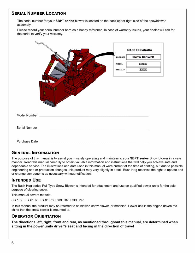
The serial number for your SBPT series blower is located on the back upper right side of the snowblower assembly.Please record your serial number here as a handy reference. In case of warranty issues, your dealer will ask for the serial to verify your warranty.
Serial Number Location
General InformationThe purpose of this manual is to assist you in safely operating and maintaining your SBPT series Snow Blower in a safe manner. Read this manual carefully to obtain valuable information and instructions that will help you achieve safe and dependable service. The illustrations and data used in this manual were current at the time of printing, but due to possible engineering and or production changes, this product may vary slightly in detail. Bush Hog reserves the right to update and or change components as necessary without notification.
Intended UseThe Bush Hog series Pull Type Snow Blower is intended for attachment and use on qualified power units for the sole purpose of clearing snow.This manual covers models:SBPT60 � SBPT68 � SBPT78 � SBPT87 � SBPT97
In this manual the product may be referred to as blower, snow blower, or machine. Power unit is the engine driven ma-chine that the snow blower is mounted to.
Operator OrientationThe directions left, right, front and rear, as mentioned throughout this manual, are determined when sitting in the power units driver’s seat and facing in the direction of travel
6
!This Safety Alert Symbol means:
ATTENTION!BECOME ALERT!
YOUR SAFETY IS INVOLVED!
The Safety Alert symbol identifies important safety messages on the snow blower and in the manual. When you see this symbol, read and understand the message, be alert to the potential
hazard in the message. Follow the instructions in the safety message.
Throughout this manual, the terms DANGER, WARNING, CAUTION and IMPORTANT are used to indicate the degree of hazard to personnel if proper safety procedures and guidelines are not followed. The appropriate term for each message has been selected using the following guide-lines:
DANGER - Indicates an imminently hazardous situation that, if not avoided, will result in death or serious injury, and includes most extreme situations typically for snow blower compon-ents which, for functional purposes, cannot be guarded.
WARNING - Indicates a potentially hazardous situation that, if not avoided, could result in death or serious injury, and includes hazards that are exposed when guards are removed. It may also be used to alert against unsafe practices.
CAUTION - Indicates a potentially hazardous situation that, if not avoided, may result in minor or moderate injury. It may also be used to alert against unsafe practices.
IMPORTANT - Indicates a situation that could result in damage to the snow blower or other property.
Safety Messages
Safety
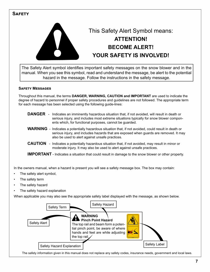
In the owners manual, when a hazard is present you will see a safety message box. The box may contain:• The safety alert symbol, • The safety term • The safety hazard• The safety hazard explanationWhen applicable you may also see the appropriate safety label displayed with the message, as shown below.
!WARNINGPinch Point Hazard
The top rail and beam form a poten-tial pinch point, be aware of where hands and feet are while adjusting the top rail. SL00002
Safety Label
Safety Alert
Safety HazardSafety Term
Safety Hazard Explanation
The safety information given in this manual does not replace any safety codes, insurance needs, government and local laws.
7
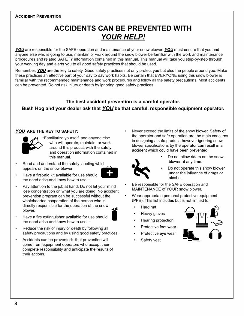
• Never exceed the limits of the snow blower. Safety of the operator and safe operation are the main concerns in designing a safe product, however ignoring snow blower specifications by the operator can result in a accident which could have been prevented.
• Do not allow riders on the snow blower at any time.
• Do not operate this snow blower under the influence of drugs or alcohol.
• Be responsible for the SAFE operation and MAINTENANCE of YOUR snow blower.
• Wear appropriate personal protective equipment (PPE). This list includes but is not limited to:• Hard hat• Heavy gloves• Hearing protection• Protective foot wear • Protective eye wear• Safety vest
Accident Prevention
ACCIDENTS CAN BE PREVENTED WITHYOUR HELP!
YOU are responsible for the SAFE operation and maintenance of your snow blower. YOU must ensure that you and anyone else who is going to use, maintain or work around the snow blower be familiar with the work and maintenance procedures and related SAFETY information contained in this manual. This manual will take you step-by-step through your working day and alerts you to all good safety practices that should be used.Remember, YOU are the key to safety. Good safety practices not only protect you but also the people around you. Make these practices an effective part of your day to day work habits. Be certain that EVERYONE using this snow blower is familiar with the recommended maintenance and work procedures and follow all the safety precautions. Most accidents can be prevented. Do not risk injury or death by ignoring good safety practices.
The best accident prevention is a careful operator. Bush Hog and your dealer ask that YOU be that careful, responsible equipment operator.
YOU ARE THE KEY TO SAFETY:• Familiarize yourself, and anyone else
who will operate, maintain, or work around this product, with the safety and operation information contained in this manual.
• Read and understand the safety labeling which appears on the snow blower.
• Have a first-aid kit available for use should the need arise and know how to use it.
• Pay attention to the job at hand. Do not let your mind lose concentration on what you are doing. No accident prevention program can be successful without the wholehearted cooperation of the person who is directly responsible for the operation of the snow blower.
• Have a fire extinguisher available for use should the need arise and know how to use it.
• Reduce the risk of injury or death by following all safety precautions and by using good safety practices.
• Accidents can be prevented: that prevention will come from equipment operators who accept their complete responsibility and anticipate the results of their actions.
8
Safety GuidelinesSafety of the operator and bystanders is one of the chief concerns in developing and designing equipment. However, every year many accidents occur which could have been avoided by a few seconds of thought and a more cautious approach to handling equipment. An operators responsibility is the safe operation of the equipment. You, the operator, can avoid many accidents by observing the following precautions in this section. To avoid personal injury or death, study the following precautions and insist those working with you, or for you to follow them.In addition to the design and configuration of this snow blower, including safety labels and safety devices, hazard control and accident prevention are dependent upon the awareness, concern, and proper training of personnel involved in the operation, transport, maintenance, and storage of the snow blower. Refer also to safety messages and operation instruction in each of the appropriate sections of the power unit and snow blower manuals. Pay close attention to the safety labeling affixed to the snow blower.1. In order to provide a better view, certain illustrations
in this manual may show an assembly with a safety device removed. However, equipment should never be used in this condition. Keep all safety devices in place, if removal becomes necessary for repairs, replace the device prior to use.
2. Replace any safety label or instruction sign that is unreadable or is missing. Location of safety signs is indicated in this manual.
3. Never use alcoholic beverages or drugs which can hinder alertness or coordination while using this snow blower. Consult your doctor about using this snow blower while taking prescription medications.
4. Under no circumstances should young children be allowed to work with this snow blower.
5. This snow blower is dangerous to persons unfamiliar with its operation. Do not allow persons to use or maintain this unit until they have read this manual and have developed a thorough understanding of the safety precautions and of how it works. Review the safety instructions with all users annually.
6. If the elderly are assisting with work, their physical limitations need to be recognized and accommodated. Assistants should be a responsible, properly trained and physically able person familiar with machinery and trained in this snow blower’s operations.
7. Never exceed the limits of the snow blower. If its ability to do a job, or to do so safely, is in question - DON’T TRY IT.
8. Do not modify the snow blower in any way. Unauthorized modification may result in serious injury or death and may impair the function and life of the snow blower.
• Train all new personnel with the instructions alongside the snow blower. Be certain only a properly trained and physically able person will use the machinery.
• Working with unfamiliar equipment can lead to careless injuries. If this snow blower is used by any person other than yourself, or is loaned or rented, it is the snow blower owner’s responsibility to make certain that the operator, prior to using:
• Reads and understands the operator’s manuals. • Is instructed in safe and proper use of the snow blower.
• If the elderly are assisting with the work, their physical limitations need to be recognized and accommodated.
Safety Training
A person who has not been trained or has not read and understood all use and safety instructions is not qualified to use the snow blower. An untrained operator exposes himself and bystanders to possible serious injury or death.
• Operators or maintenance personnel who are not fully able to read and understand this manual should not operate or work on the snow blower until suitably trained:
• Make certain that all operators and maintenance personnel have complete understanding of the full and exact contents of this manual and safety labeling.
• ALL information contained in this manual and labeling on the snow blower must be conveyed CLEARLY and FULLY, in order to be able to operate safely and knowledgeably.
• Review the snow blower and instructions regularly with existing workers.
9
Preparation1. Inspect snow blower for shipping damage. If damage
does exist, do not use. Notify your dealer immediately to have damaged parts replaced or repaired.
2. Ensure safety guards, attach points, power unit tires are not damaged and in good condition.
3. Inspect all fasteners that they are not loose or missing. Ensure fasteners and wheel bolts are torqued according to the torque chart at the back of this manual.
4. If traveling at night, ensure provincial state and local laws for lighting requirements have been met.
5. Ensure that all applicable safety decals are installed and legible.
6. Personal protection equipment (PPE) including hard hat, safety glasses, safety shoes, and gloves are recommended during assembly, installation, operation, adjustment, maintaining, repairing, removal, cleaning, or moving the unit. Do not allow long hair, loose fitting clothing or jewelry to be around equipment.
7. PROLONGED EXPOSURE TO LOUD NOISE MAY CAUSE PERMANENT HEARING LOSS! Gas or diesel powered equipment can often be noisy enough to cause permanent, partial hearing loss. We recommend that you wear hearing protection on a full-time basis. Noise over 85dB on a long-term basis can cause severe hearing loss. Noise over 90db adjacent to the Operator over a long-term basis may cause permanent, total hearing loss.
8. When not attached to the power unit, secure the unit to prevent movement.
9. Check wiring harness connection and test functions if applicable.
1. NEVER allow helpers or bystanders under or near the snow blower.
2. Make sure that the snow blower is fastened securely to the power unit before moving.
3. Inspect all fastening devices, do not use if worn or damaged.
4. Make sure that everyone is clear before moving the snow blower. NEVER position yourself between the powering unit and the snow blower.
5. Do not permit riders while using this snow blower.6. Where possible, avoid operating near ditches,
embankments and holes. 7. Snow clearing speed is dependent upon many
factors which includes but is not limited to: visibility, obstructions, surface condition. Never exceed 15 km/h (10 mph) while clearing snow. Serious personal injury can result from clearing at excessive speeds if an obstruction is encountered.
8. Travelling between job sites, do not exceed 40 km/h (25 mph). Ensure slow-moving-vehicle (SMV) emblem has been properly installed at rear of power unit or snow blower if the power unit SMV is obscured.
9. Avoid distractions and pay attention to the job at hand: wait until it is safe to operate mobile communication equipment such as cell phones, text messaging devices, pagers or two-way radios.
10. Always wear the seat belt, if equipped, when clearing snow. Sudden contact with a hidden object can result in serious personal injury.
11. Inspect areas to be cleared before snowfall for potential hazards, and mark obstructions with stakes that will be seen when snow covers the ground.
12. Always lower the snow blower to the ground when not in use.
13. When moving in reverse, turn and look behind you instead of relying on vehicle mirrors.
14. When exiting or entering your power unit, use caution, the entry area may be slippery from snow and ice buildup.
Storage Safety
1. Store the unit in an area away from human activity.2. Do not allow children to play on or around the stored
snow blower.3. Store the unit in a dry, level area. Cover if stored
outside.4. Guard any sharp corners.5. Ensure components and safety features are not
damaged and in good condition before storing the snow blower. Make repairs to be ready for the following season.
6. Secure the snow blower to prevent unwanted movement.
Operation Safety
10
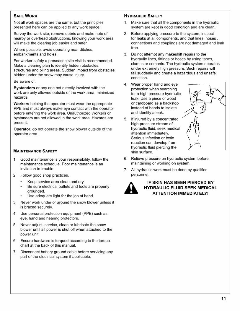
Hydraulic Safety1. Make sure that all the components in the hydraulic
system are kept in good condition and are clean.2. Before applying pressure to the system, inspect
for leaks at all components, and that lines, hoses , connections and couplings are not damaged and leak free.
3. Do not attempt any makeshift repairs to the hydraulic lines, fittings or hoses by using tapes, clamps or cements. The hydraulic system operates under extremely high pressure. Such repairs will fail suddenly and create a hazardous and unsafe condition.
4. Wear proper hand and eye protection when searching for a high pressure hydraulic leak. Use a piece of wood or cardboard as a backstop instead of hands to isolate and identify a leak.
5. If injured by a concentrated high-pressure stream of hydraulic fluid, seek medical attention immediately. Serious infection or toxic reaction can develop from hydraulic fluid piercing the skin surface.
6. Relieve pressure on hydraulic system before maintaining or working on system.
7. All hydraulic work must be done by qualified personnel.
Safe WorkNot all work spaces are the same, but the principles presented here can be applied to any work space.Survey the work site, remove debris and make note of nearby or overhead obstructions, knowing your work area will make the clearing job easier and safer.Where possible, avoid operating near ditches, embankments and holes. For worker safety a preseason site visit is recommended. Make a clearing plan to identify hidden obstacles, structures and piling areas. Sudden impact from obstacles hidden under the snow may cause injury.Be aware of:Bystanders or any one not directly involved with the work are only allowed outside of the work area, minimized hazards.Workers helping the operator must wear the appropriate PPE and must always make eye contact with the operator before entering the work area. Unauthorized Workers or bystanders are not allowed in the work area. Hazards are present.Operator, do not operate the snow blower outside of the operator area.
Maintenance Safety
1. Good maintenance is your responsibility, follow the maintenance schedule. Poor maintenance is an invitation to trouble.
2. Follow good shop practices.• Keep service area clean and dry.• Be sure electrical outlets and tools are properly
grounded.• Use adequate light for the job at hand.
3. Never work under or around the snow blower unless it is braced securely.
4. Use personal protection equipment (PPE) such as eye, hand and hearing protectors.
5. Never adjust, service, clean or lubricate the snow blower until all power is shut off when attached to the power unit.
6. Ensure hardware is torqued according to the torque chart at the back of this manual.
7. Disconnect battery ground cable before servicing any part of the electrical system if applicable.
IF SKIN HAS BEEN PIERCED BY HYDRAULIC FLUID SEEK MEDICAL
ATTENTION IMMEDIATELY!
Operation Safety
11
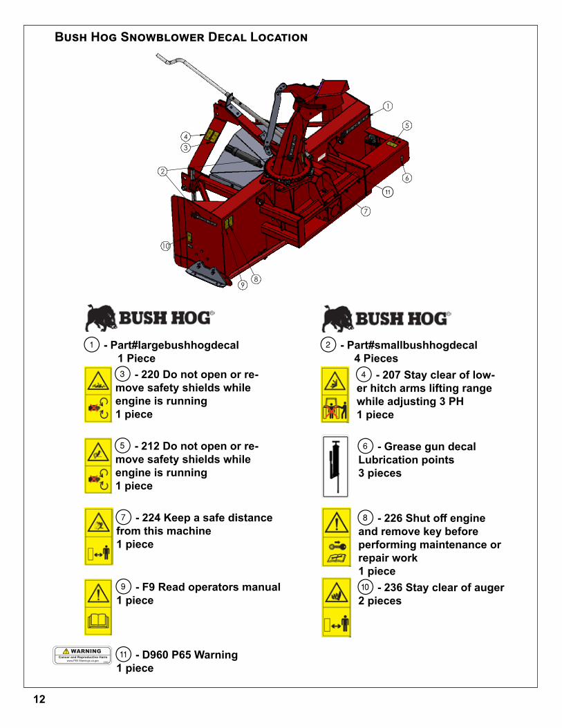
Bush Hog Snowblower Decal Location
THIRD ANGLE PROJECTION
34
1
5
6
7
2
10
98
5 4 3 1
Folder
S:\Solidworks\Solidworks_Elo\Snowblower\75 PT\78 PT Blower 2017\78 PT Blower 2017.SLDASM
DWG. NO.
REV
Model
SCALE 1:48 SHEET 2 OF2
DATE DRAWN
MATERIAL
78 PT Blower 2017June-02-17 9:00:08 AM
DESCRIPTION 78 PT Blower 2017 Assembly
S:\Solidworks\Solidworks_Elo\Snowblower\75 PT\78 PT Blower 2017\
Weight(lbs.)0Width Height Length
0 0 914.93 0Blank Size Unit of Measure
ITEM ID. 35912Config ID Bush hog decals
DIMENSIONS ARE IN INCHESTOLERANCES NON SPECIFIED:FRACTIONAL 1/64 BEND 1.0TWO PLACE DECIMAL 0.01"THREE PLACE DECIMAL 0.002"
Notes
DO NOT SCALE DRAWING
1 - Part#largebushhogdecal 1 Piece
2 - Part#smallbushhogdecal 4 Pieces
3 - 220 Do not open or re-move safety shields while engine is running1 piece
4 - 207 Stay clear of low-er hitch arms lifting range while adjusting 3 PH1 piece
5 - 212 Do not open or re-move safety shields while engine is running1 piece
6 - Grease gun decalLubrication points3 pieces
7 - 224 Keep a safe distancefrom this machine1 piece
8 - 226 Shut off engine and remove key beforeperforming maintenance orrepair work1 piece
9 - F9 Read operators manual1 piece
) - 236 Stay clear of auger2 pieces
!
Cancer and R
eproductive H
arm
www.P65 Warnings.c
a.govD960
WAR
NING
! - D960 P65 Warning1 piece
Cancer and Reproductive Harmwww.P65 Warnings.ca.gov
D960
WARNING
12
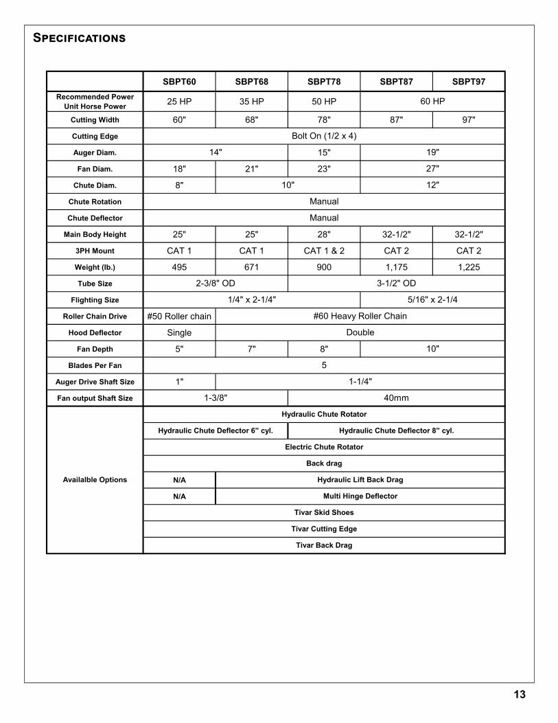
Models SBPT60 SBPT68 SBPT78 SBPT87 SBPT97Recommended Power
Unit Horse Power 25 HP 35 HP 50 HP
Cutting Width 60" 68" 78" 87" 97"
Cutting Edge
Auger Diam. 15"
Fan Diam. 18" 21" 23"
Chute Diam. 8"
Chute Rotation
Chute Deflector
Main Body Height 25" 25" 28" 32-1/2" 32-1/2"
3PH Mount CAT 1 CAT 1 CAT 1 & 2 CAT 2 CAT 2
Weight (lb.) 495 671 900 1,175 1,225
Tube Size
Flighting Size
Roller Chain Drive #50 Roller chain
Hood Deflector Single
Fan Depth 5" 7" 8"
Blades Per Fan
Auger Drive Shaft Size 1"
Fan output Shaft Size
N/A
N/A
60 HP
2-3/8" OD 3-1/2" OD
Hydraulic Chute Rotator
Double
5
1-1/4"
10"
1-3/8" 40mm
Manual
Manual
1/4" x 2-1/4" 5/16" x 2-1/4
#60 Heavy Roller Chain
10"
Availalble Options
Bolt On (1/2 x 4)
Hydraulic Chute Deflector 6” cyl. Hydraulic Chute Deflector 8” cyl.
Electric Chute Rotator
Back drag
Tivar Skid Shoes
Tivar Back Drag
19"
12"
27"
14"
Tivar Cutting Edge
Hydraulic Lift Back Drag
Multi Hinge Deflector
Specifications
13

Sign Off FormBush Hog follows the general Safety Standards specified by the American Society of Agricultural and Biological Engineers (ASABE) and the Occupational Health and Safety Administration (OSHA). Anyone who will be operating and or maintaining the equipment must read and clearly understand ALL safety operating and maintenance instructions presented in this manual. Do not operate or allow anyone else to operate this equipment until such information has been reviewed. Annually review this information before the season start-up. Make these reviews of SAFETY and OPERATION annually as a standard practice for all your equipment. An untrained operator is unqualified to operate this machine. A sign-off sheet is provided for your record keeping to show that all personnel who will be working with the equipment have read and understood the information in the operator’s manual and have been instructed in the operation of the equipment.
Date Employees Signature Employers Signature
14
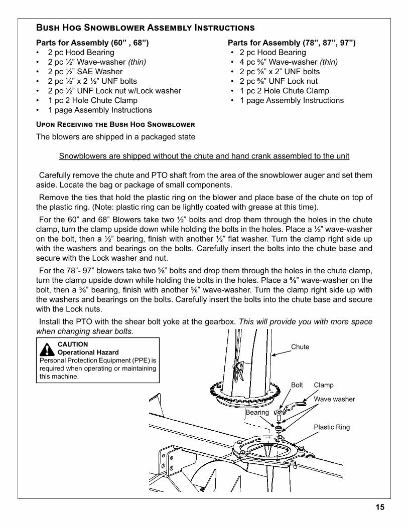
Bush Hog Snowblower Assembly Instructions Parts for Assembly (78”, 87”, 97”)• 2 pc Hood Bearing• 4 pc 5/8” Wave-washer (thin)• 2 pc 5/8” x 2” UNF bolts• 2 pc 5/8” UNF Lock nut • 1 pc 2 Hole Chute Clamp• 1 page Assembly Instructions
Upon Receiving the Bush Hog SnowblowerThe blowers are shipped in a packaged state
Snowblowers are shipped without the chute and hand crank assembled to the unit
Carefully remove the chute and PTO shaft from the area of the snowblower auger and set them aside. Locate the bag or package of small components.Remove the ties that hold the plastic ring on the blower and place base of the chute on top of
the plastic ring. (Note: plastic ring can be lightly coated with grease at this time).For the 60” and 68” Blowers take two 1/2” bolts and drop them through the holes in the chute
clamp, turn the clamp upside down while holding the bolts in the holes. Place a 1/2” wave-washer on the bolt, then a 1/2” bearing, finish with another 1/2” flat washer. Turn the clamp right side up with the washers and bearings on the bolts. Carefully insert the bolts into the chute base and secure with the Lock washer and nut.For the 78”- 97” blowers take two 5/8” bolts and drop them through the holes in the chute clamp,
turn the clamp upside down while holding the bolts in the holes. Place a 5/8” wave-washer on the bolt, then a 5/8” bearing, finish with another 5/8” wave-washer. Turn the clamp right side up with the washers and bearings on the bolts. Carefully insert the bolts into the chute base and secure with the Lock nuts.Install the PTO with the shear bolt yoke at the gearbox. This will provide you with more space
when changing shear bolts.
Chute
Bolt Clamp
Wave washer
Bearing
Plastic Ring
Parts for Assembly (60” , 68”)• 2 pc Hood Bearing• 2 pc 1/2” Wave-washer (thin)• 2 pc 1/2” SAE Washer• 2 pc 1/2” x 2 1/2” UNF bolts• 2 pc 1/2” UNF Lock nut w/Lock washer• 1 pc 2 Hole Chute Clamp• 1 page Assembly Instructions
!CAUTIONOperational Hazard
Personal Protection Equipment (PPE) is required when operating or maintaining this machine.
15
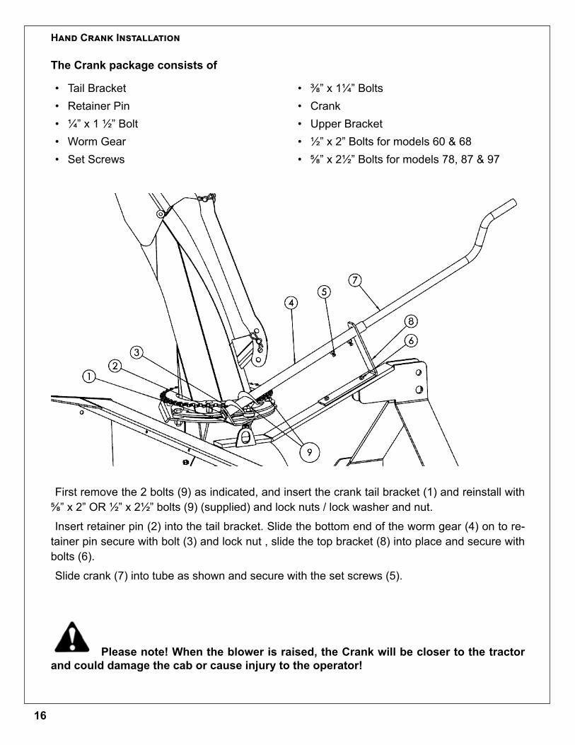
Hand Crank Installation
• Tail Bracket• Retainer Pin• 1/4” x 1 1/2” Bolt• Worm Gear • Set Screws
• 3/8” x 11/4” Bolts • Crank • Upper Bracket• 1/2” x 2” Bolts for models 60 & 68• 5/8” x 21/2” Bolts for models 78, 87 & 97
First remove the 2 bolts (9) as indicated, and insert the crank tail bracket (1) and reinstall with 5/8” x 2” OR 1/2” x 21/2” bolts (9) (supplied) and lock nuts / lock washer and nut.
Insert retainer pin (2) into the tail bracket. Slide the bottom end of the worm gear (4) on to re-tainer pin secure with bolt (3) and lock nut , slide the top bracket (8) into place and secure with bolts (6).
Slide crank (7) into tube as shown and secure with the set screws (5).
Please note! When the blower is raised, the Crank will be closer to the tractor and could damage the cab or cause injury to the operator!
The Crank package consists of
16
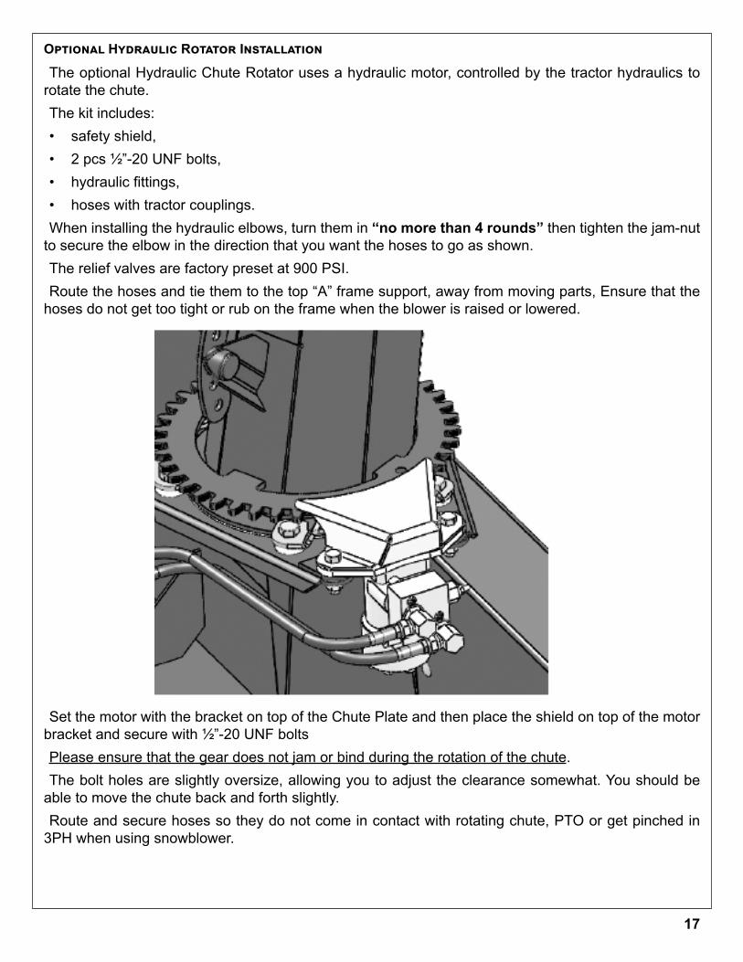
The optional Hydraulic Chute Rotator uses a hydraulic motor, controlled by the tractor hydraulics to rotate the chute. The kit includes: • safety shield, • 2 pcs 1/2”-20 UNF bolts, • hydraulic fittings, • hoses with tractor couplings.When installing the hydraulic elbows, turn them in “no more than 4 rounds” then tighten the jam-nut
to secure the elbow in the direction that you want the hoses to go as shown.The relief valves are factory preset at 900 PSI.Route the hoses and tie them to the top “A” frame support, away from moving parts, Ensure that the
hoses do not get too tight or rub on the frame when the blower is raised or lowered.
Set the motor with the bracket on top of the Chute Plate and then place the shield on top of the motor bracket and secure with 1/2”-20 UNF bolts Please ensure that the gear does not jam or bind during the rotation of the chute. The bolt holes are slightly oversize, allowing you to adjust the clearance somewhat. You should be
able to move the chute back and forth slightly.Route and secure hoses so they do not come in contact with rotating chute, PTO or get pinched in
3PH when using snowblower.
Optional Hydraulic Rotator Installation
17
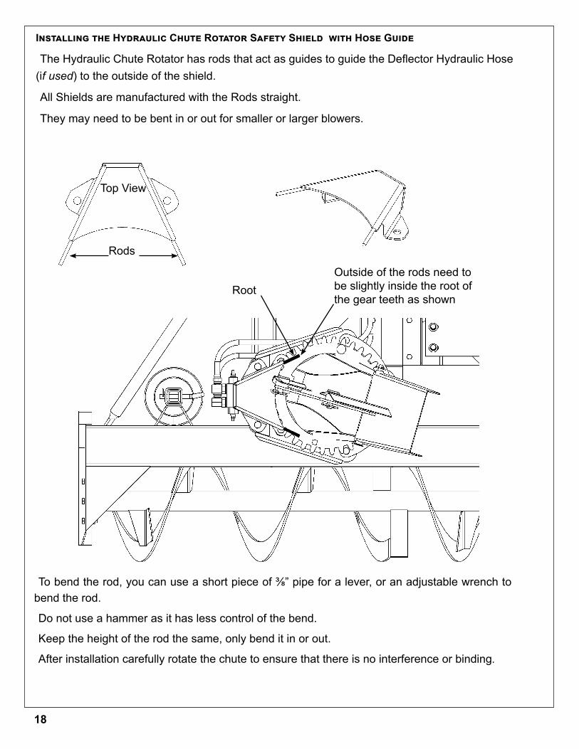
Installing the Hydraulic Chute Rotator Safety Shield with Hose Guide
The Hydraulic Chute Rotator has rods that act as guides to guide the Deflector Hydraulic Hose (if used) to the outside of the shield.
All Shields are manufactured with the Rods straight.
They may need to be bent in or out for smaller or larger blowers.
Top View
Rods
Outside of the rods need to be slightly inside the root of the gear teeth as shown
To bend the rod, you can use a short piece of 3/8” pipe for a lever, or an adjustable wrench to bend the rod.
Do not use a hammer as it has less control of the bend.
Keep the height of the rod the same, only bend it in or out.
After installation carefully rotate the chute to ensure that there is no interference or binding.
Root
18
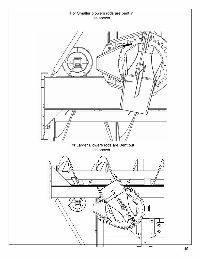
For Smaller blowers rods are bent in as shown
For Larger Blowers rods are Bent outas shown
19
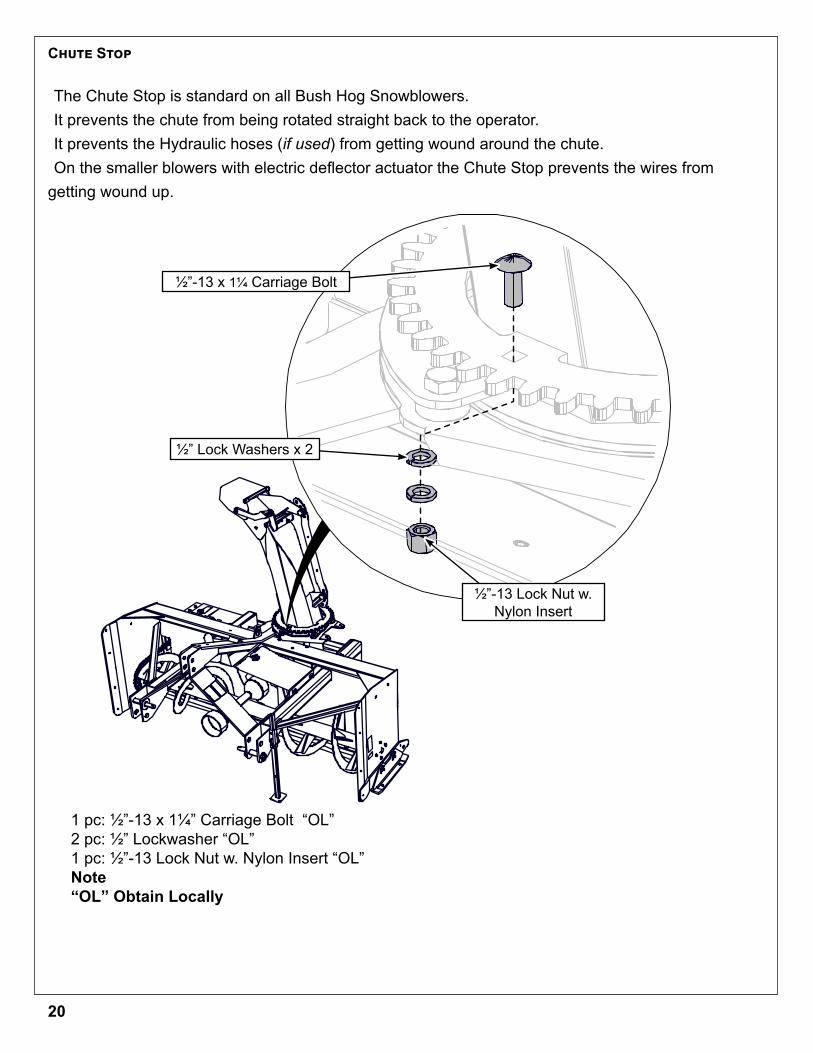
1 pc: 1/2”-13 x 11/4” Carriage Bolt “OL”2 pc: 1/2” Lockwasher “OL”1 pc: 1/2”-13 Lock Nut w. Nylon Insert “OL”Note“OL” Obtain Locally
Chute Stop
The Chute Stop is standard on all Bush Hog Snowblowers. It prevents the chute from being rotated straight back to the operator.It prevents the Hydraulic hoses (if used) from getting wound around the chute.On the smaller blowers with electric deflector actuator the Chute Stop prevents the wires from
getting wound up.
1/2”-13 x 11/4 Carriage Bolt
1/2”-13 Lock Nut w. Nylon Insert
1/2” Lock Washers x 2
20
Sizing PTO Drive-line
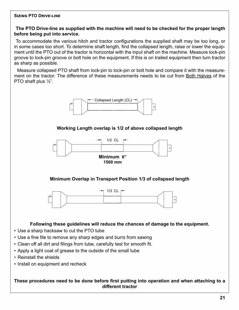
The PTO Drive-line as supplied with the machine will need to be checked for the proper length before being put into service.To accommodate the various hitch and tractor configurations the supplied shaft may be too long, or
in some cases too short. To determine shaft length, find the collapsed length, raise or lower the equip-ment until the PTO out of the tractor is horizontal with the input shaft on the machine. Measure lock-pin groove to lock-pin groove or bolt hole on the equipment. If this is on trailed equipment then turn tractor as sharp as possible. Measure collapsed PTO shaft from lock-pin to lock-pin or bolt hole and compare it with the measure-
ment on the tractor. The difference of these measurements needs to be cut from Both Halves of the PTO shaft plus 1/2”.
Working Length overlap is 1/2 of above collapsed length
Minimum Overlap in Transport Position 1/3 of collapsed length
Following these guidelines will reduce the chances of damage to the equipment. • Use a sharp hacksaw to cut the PTO tube• Use a fine file to remove any sharp edges and burrs from sawing• Clean off all dirt and filings from tube, carefully test for smooth fit. • Apply a light coat of grease to the outside of the small tube• Reinstall the shields• Install on equipment and recheck
These procedures need to be done before first putting into operation and when attaching to a different tractor
THIRD ANGLE PROJECTION
1/2 CL
1/3 CL
5 4 3 1
Folder
DWG. NO.
REV
Model
SCALE 1:4 SHEET 1 OF1
DATE DRAWN
MATERIAL
PTO SketchsJanuary-12-17 4:23:36 PM
DESCRIPTION
Weight(lbs.)Width Height Length Blank Size Unit of Measure
ITEM ID.
Config ID
DIMENSIONS ARE IN INCHESTOLERANCES NON SPECIFIED:FRACTIONAL 1/64 BEND 1.0TWO PLACE DECIMAL 0.01"THREE PLACE DECIMAL 0.002"
Notes
DO NOT SCALE DRAWING
THIRD ANGLE PROJECTION
Colapsed Lenght ( CL )
1/2 CL
5 4 3 1
Folder
DWG. NO.
REV
Model
SCALE 1:4 SHEET 1 OF1
DATE DRAWN
MATERIAL
PTO SketchsJanuary-12-17 4:23:36 PM
DESCRIPTION
Weight(lbs.)Width Height Length Blank Size Unit of Measure
ITEM ID.
Config ID
DIMENSIONS ARE IN INCHESTOLERANCES NON SPECIFIED:FRACTIONAL 1/64 BEND 1.0TWO PLACE DECIMAL 0.01"THREE PLACE DECIMAL 0.002"
Notes
DO NOT SCALE DRAWING
Minimum 6” 1500 mm
1/2 CL
1/3 CL
Collapsed Length (CL)
21
For Better PTO Shaft and Gearbox OperationA proper initial installation will give you years of satisfactory service on your equipment. Please read carefully, following instructions which have been specially made to help you and make you satisfied with your purchase.
Warning! Unfortunately, snowblowers will be faced with forgotten orhidden objects under the snow, such as: chain, tires, stones, pieces of wood, etc. In spite of all our efforts, machines are not built to resist all those conditions.
Danger: Too big tractors It is dangerous to use a tractor that is too big or too powerful. The tractor will always be able to
overload the blower, even if the machine is already at maximum capacity. Tractor being veryhigh, too large angles at PTO universal joints will result, and the life of the universal joints will be shortened dramatically.P T O Shaft angles
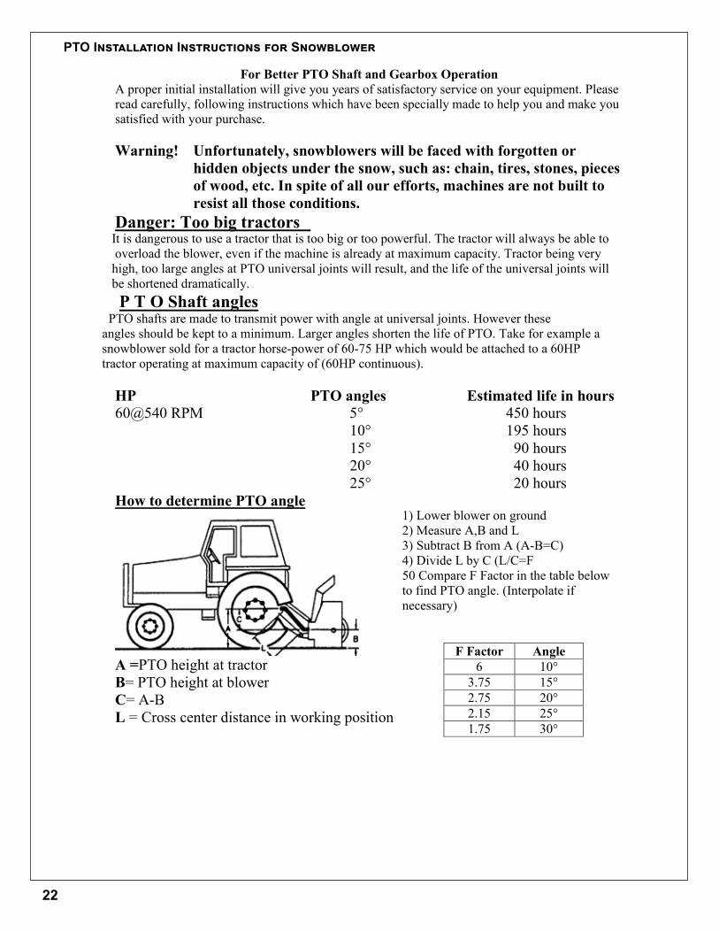
PTO shafts are made to transmit power with angle at universal joints. However theseangles should be kept to a minimum. Larger angles shorten the life of PTO. Take for example asnowblower sold for a tractor horse-power of 60-75 HP which would be attached to a 60HPtractor operating at maximum capacity of (60HP continuous).
HP PTO angles Estimated life in hours60@540 RPM 5° 450 hours
10° 195 hours15° 90 hours20° 40 hours25° 20 hours
How to determine PTO angle
A =PTO height at tractorB= PTO height at blowerC= A-BL = Cross center distance in working position
1) Lower blower on ground2) Measure A,B and L3) Subtract B from A (A-B=C)4) Divide L by C (L/C=F50 Compare F Factor in the table belowto find PTO angle. (Interpolate ifnecessary)
F Factor Angle6 10°
3.75 15°2.75 20°2.15 25°1.75 30°
PTO Installation Instructions for Snowblower
22
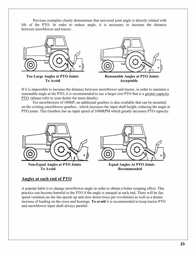
Previous examples clearly demonstrate that universal joint angle is directly related with life of the PTO. In order to reduce angle, it is necessary to increase the distance between snowblower and tractor.
Too Large Angles at PTO Joints Reasonable Angles at PTO JointsTo Avoid Acceptable
If it is impossible to increase the distance between snowblower and tractor, in order to maintain a reasonable angle at the PTO, it is recommended to use a larger size PTO that is a greater capacity PTO. (please refer to your dealer for more details).
For snowblowers of 100HP, an additional gearbox is also available that can be mounted on the existing snowblower gearbox , which increases the input shaft height, reducing the angle at PTO joints. This Gearbox has an input speed of 1000RPM which greatly increases PTO capacity.
Non-Equal Angles at PTO Joints Equal Angles At PTO JointsTo Avoid Recommended
Angles at each end of PTO
A popular habit is to change snowblower angle in order to obtain a better scraping effect. This practice can become harmful to the PTO if the angle is unequal at each end, There will be fan speed variation (as the fan speeds up and slow down twice per revolution) as well as a drastic increase of loading on the cross and bearings. To avoid it is recommended to keep tractor PTO and snowblower input shaft always parallel.
23

Shear Bolts
Shear bolts are built to break under shock loads on the fan or auger. However under certain circumstances this security is not adequate. Example: a sudden high impact shock on the fan may, in some cases break the fan shaft without breaking the shear bolt.
If the shear bolt breaks, make sure to always replace it with the same grade of bolt (grade 5 for PTO series 20-40-50-60, and grade 8 for PTO series 80) it is necessary to always maintain this bolt very tight in order to keep the efficiency of the shearing mechanism.
Warning: The gearbox shafts are made with special alloy steel. However they are case hardened to increase capacity to shock load. These shafts cannot be broken under normal loads. However undesirable objects may enter the fan and either bend or break the gearbox shaft. It is understood that the gearbox cannot be built to resist every possible overload and consequently, gearbox fan shafts will not be replaced under warranty. Therefore the user of the snowblower must be verycareful.
Maximum length of PTO shaft
Warning: Telescopic tubes of PTO should overlap a minimum length to meet idealconditions for transmitting power.
Following table could be used as a guide to find maximum permissible length of PTO.
PTO Description Over-all lengthClosed
Over-all lengthOpened Max
Telescopic tubeoverlap
T20-056P 29 3/4" 41" 5"T40-056P 30 1/2" 40 1/2" 6"T50-071P 36 1/2" 51 1/4" 7"T60-071P 37 3/4" 511/4" 7"T80-066P 36" 47 1/4" 7"T80-076P 40 1/2" 53" 8"T90-071P 39" 51" 8"
24
!CAUTIONOperational Hazard
Tractor PTO must operate at 540 RPM only. Exceeding the snow blower’s design speed of 540 RPM will result in operator injury or damage to the machine.
!CAUTIONOperational Hazard
Personal Protection Equipment (PPE) is required when operating or maintaining this machine.
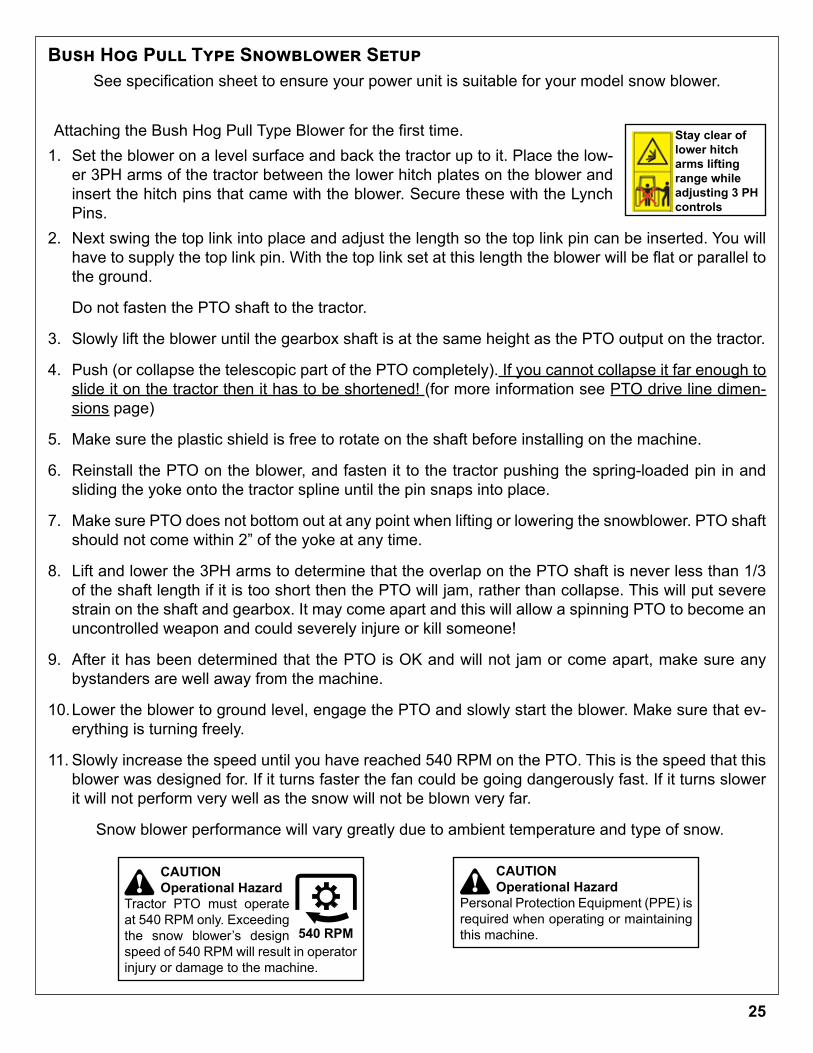
Attaching the Bush Hog Pull Type Blower for the first time.1. Set the blower on a level surface and back the tractor up to it. Place the low-
er 3PH arms of the tractor between the lower hitch plates on the blower and insert the hitch pins that came with the blower. Secure these with the Lynch Pins.
2. Next swing the top link into place and adjust the length so the top link pin can be inserted. You will have to supply the top link pin. With the top link set at this length the blower will be flat or parallel to the ground.
Do not fasten the PTO shaft to the tractor.
3. Slowly lift the blower until the gearbox shaft is at the same height as the PTO output on the tractor.
4. Push (or collapse the telescopic part of the PTO completely). If you cannot collapse it far enough to slide it on the tractor then it has to be shortened! (for more information see PTO drive line dimen-sions page)
5. Make sure the plastic shield is free to rotate on the shaft before installing on the machine.
6. Reinstall the PTO on the blower, and fasten it to the tractor pushing the spring-loaded pin in and sliding the yoke onto the tractor spline until the pin snaps into place.
7. Make sure PTO does not bottom out at any point when lifting or lowering the snowblower. PTO shaft should not come within 2” of the yoke at any time.
8. Lift and lower the 3PH arms to determine that the overlap on the PTO shaft is never less than 1/3 of the shaft length if it is too short then the PTO will jam, rather than collapse. This will put severe strain on the shaft and gearbox. It may come apart and this will allow a spinning PTO to become an uncontrolled weapon and could severely injure or kill someone!
9. After it has been determined that the PTO is OK and will not jam or come apart, make sure any bystanders are well away from the machine.
10. Lower the blower to ground level, engage the PTO and slowly start the blower. Make sure that ev-erything is turning freely.
11. Slowly increase the speed until you have reached 540 RPM on the PTO. This is the speed that this blower was designed for. If it turns faster the fan could be going dangerously fast. If it turns slower it will not perform very well as the snow will not be blown very far.
Snow blower performance will vary greatly due to ambient temperature and type of snow.
Stay clear of lower hitch arms lifting range while adjusting 3 PH controls
Bush Hog Pull Type Snowblower SetupSee specification sheet to ensure your power unit is suitable for your model snow blower.
25
!CAUTIONOperational Hazard
Personal Protection Equipment (PPE) is required when operating or maintaining this machine.
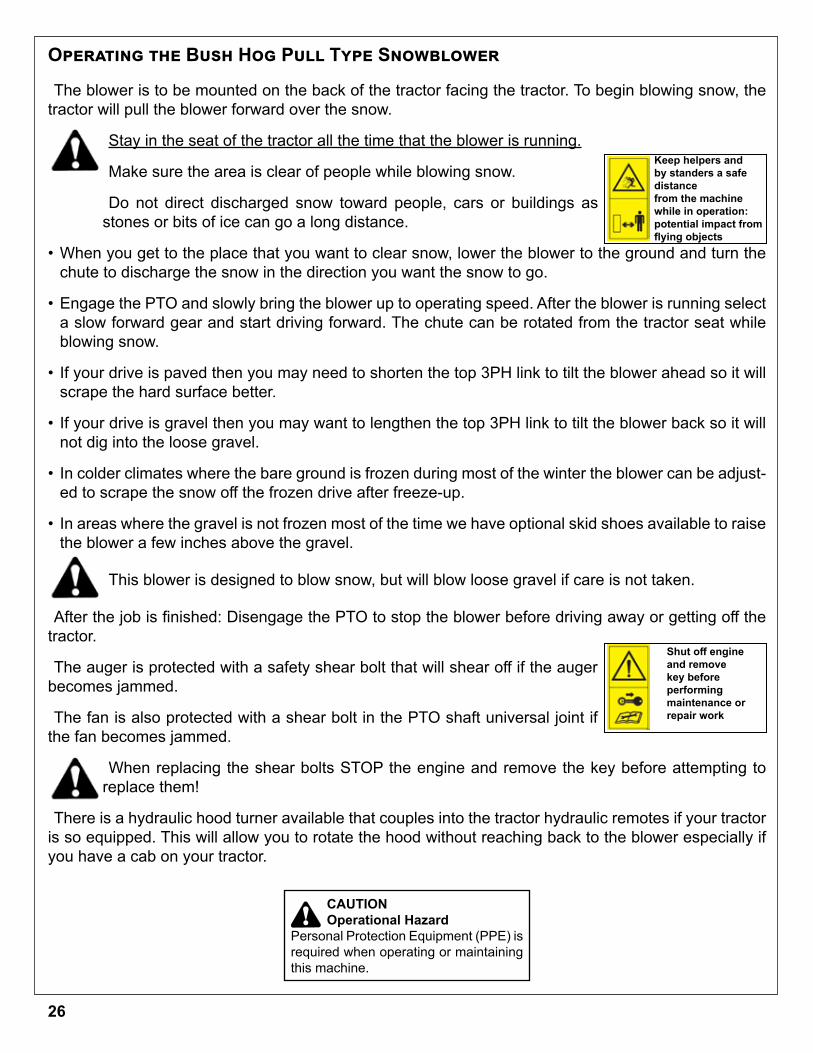
Operating the Bush Hog Pull Type Snowblower
The blower is to be mounted on the back of the tractor facing the tractor. To begin blowing snow, the tractor will pull the blower forward over the snow.
Stay in the seat of the tractor all the time that the blower is running.
Make sure the area is clear of people while blowing snow.
Do not direct discharged snow toward people, cars or buildings as stones or bits of ice can go a long distance.
• When you get to the place that you want to clear snow, lower the blower to the ground and turn the chute to discharge the snow in the direction you want the snow to go.
• Engage the PTO and slowly bring the blower up to operating speed. After the blower is running select a slow forward gear and start driving forward. The chute can be rotated from the tractor seat while blowing snow.
• If your drive is paved then you may need to shorten the top 3PH link to tilt the blower ahead so it will scrape the hard surface better.
• If your drive is gravel then you may want to lengthen the top 3PH link to tilt the blower back so it will not dig into the loose gravel.
• In colder climates where the bare ground is frozen during most of the winter the blower can be adjust-ed to scrape the snow off the frozen drive after freeze-up.
• In areas where the gravel is not frozen most of the time we have optional skid shoes available to raise the blower a few inches above the gravel.
This blower is designed to blow snow, but will blow loose gravel if care is not taken.
After the job is finished: Disengage the PTO to stop the blower before driving away or getting off the tractor.
The auger is protected with a safety shear bolt that will shear off if the auger becomes jammed.
The fan is also protected with a shear bolt in the PTO shaft universal joint if the fan becomes jammed.
When replacing the shear bolts STOP the engine and remove the key before attempting to replace them!
There is a hydraulic hood turner available that couples into the tractor hydraulic remotes if your tractor is so equipped. This will allow you to rotate the hood without reaching back to the blower especially if you have a cab on your tractor.
Keep helpers and by standers a safe distancefrom the machine while in operation: potential impact from flying objects
Shut off engine and remove key beforeperforming maintenance orrepair work
26

Maintenance• 60/68 PT PTO Shear bolt -- 8 x50 mm 8.8
• 78/87/97 PTO Shear bolt – 10x55 mm 8.8
• 60/68 PT Auger Shear bolt -- 1/4”x 11/4” Gr #2
• 78/87/97 Auger Shear bolt – 5/16” x 11/4” Gr #2
• Auger Drive Chain Tightener – tighten chain allowing ¼” sag in the bottom span of chain (be-tween drive and driven sprocket).
Lubrication• Gearbox- check oil level every 50 hours. Fill to oil level plug (middle of gearbox) with SAE 90
gear oil. SAE 80W 90 gear oil may also be used.
• Auger and Shear Sprocket Bearing – grease sparingly every 50 hours. (By using too much grease you will push the seals off the bearing).
• PTO Shaft – grease every 10 hours. Pull apart and apply grease to the sliding members. Grease the yoke bearings at this time as well.
• Discharge chute mount – occasionally squirt oil on the plastic ring (this will extend the life of the plastic ring and will operate smoother).
• Auger Chain – apply oil on a regular basis especially after using the snowblower.
Storing the Snowblower in the off seasonAt the end of the season lubricate the Bearings, PTO shaft, Discharge chute mount and Auger
chain before storing it.
NotesAll fasteners are Grade #5 unless otherwise specified.
Bush Hog Pull Type Snowblower Maintenance
27
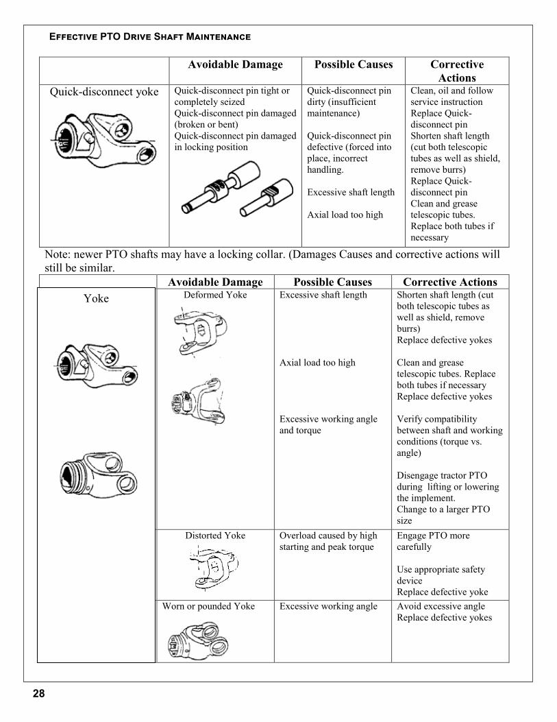
Avoidable Damage Possible Causes CorrectiveActions
Quick-disconnect yoke Quick-disconnect pin tight orcompletely seizedQuick-disconnect pin damaged(broken or bent)Quick-disconnect pin damagedin locking position
Quick-disconnect pindirty (insufficientmaintenance)
Quick-disconnect pindefective (forced intoplace, incorrecthandling.
Excessive shaft length
Axial load too high
Clean, oil and followservice instructionReplace Quick-disconnect pinShorten shaft length(cut both telescopictubes as well as shield,remove burrs)Replace Quick-disconnect pinClean and greasetelescopic tubes.Replace both tubes ifnecessary
Note: newer PTO shafts may have a locking collar. (Damages Causes and corrective actions willstill be similar.
Avoidable Damage Possible Causes Corrective ActionsDeformed Yoke Excessive shaft length
Axial load too high
Excessive working angleand torque
Shorten shaft length (cutboth telescopic tubes aswell as shield, removeburrs)Replace defective yokes
Clean and greasetelescopic tubes. Replaceboth tubes if necessaryReplace defective yokes
Verify compatibilitybetween shaft and workingconditions (torque vs.angle)
Disengage tractor PTOduring lifting or loweringthe implement.Change to a larger PTOsize
Distorted Yoke Overload caused by highstarting and peak torque
Engage PTO morecarefully
Use appropriate safetydeviceReplace defective yoke
Worn or pounded Yoke Excessive working angle Avoid excessive angleReplace defective yokes
Yoke
Effective PTO Drive Shaft Maintenance
28
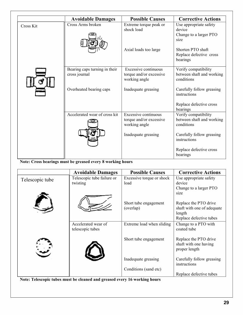
Avoidable Damages Possible Causes Corrective ActionsCross Arms broken Extreme torque peak or
shock load
Axial loads too large
Use appropriate safetydeviceChange to a larger PTOsize
Shorten PTO shaftReplace defective crossbearings
Bearing caps turning in theircross journal
Overheated bearing caps
Excessive continuoustorque and/or excessiveworking angle
Inadequate greasing
Verify compatibilitybetween shaft and workingconditions
Carefully follow greasinginstructions
Replace defective crossbearings
Accelerated wear of cross kit Excessive continuoustorque and/or excessiveworking angle
Inadequate greasing
Verify compatibilitybetween shaft and workingconditions
Carefully follow greasinginstructions
Replace defective crossbearings
Note: Cross bearings must be greased every 8 working hours
Avoidable Damages Possible Causes Corrective ActionsTelescopic tube failure ortwisting
Excessive torque or shockload
Short tube engagement(overlap)
Use appropriate safetydeviceChange to a larger PTOsize
Replace the PTO driveshaft with one of adequatelengthReplace defective tubes
Accelerated wear oftelescopic tubes
Extreme load when sliding
Short tube engagement
Inadequate greasing
Conditions (sand etc)
Change to a PTO withcoated tube
Replace the PTO driveshaft with one havingproper length
Carefully follow greasinginstructions
Replace defective tubesNote: Telescopic tubes must be cleaned and greased every 16 working hours
Cross Kit
Telescopic tube
29
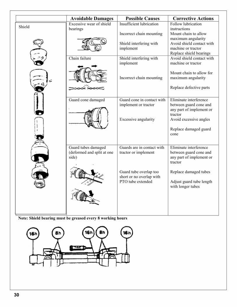
Avoidable Damages Possible Causes Corrective ActionsExcessive wear of shieldbearings
Insufficient lubrication
Incorrect chain mounting
Shield interfering withimplement
Follow lubricationinstructionsMount chain to allowmaximum angularityAvoid shield contact withmachine or tractorReplace shield bearings
Chain failure Shield interfering withimplement
Incorrect chain mounting
Avoid shield contact withmachine or tractor
Mount chain to allow formaximum angularity
Replace defective parts
Guard cone damaged Guard cone in contact withimplement or tractor
Excessive angularity
Eliminate interferencebetween guard cone andany part of implement ortractorAvoid excessive angles
Replace damaged guardcone
Guard tubes damaged(deformed and split at oneside)
Guards are in contact withtractor or implement
Guard tube overlap tooshort or no overlap withPTO tube extended
Eliminate interferencebetween guard cone andany part of implement ortractor
Replace damaged tubes
Adjust guard tube lengthwith longer tubes
Note: Shield bearing must be greased every 8 working hours
Shield
30

Bolt TorqueAs used on this machine
• Bolt torque table shown below gives torque values for various bolts used.• This chart is for non-lubricated threads.• Replace with same strength bolt.Torque Specifications. Torque values are identified by their head markings.
Diameter SAE 2 SAE 5 SAE 8“A” ft-lb N.m ft-lb N.m ft-lb N.m1/4 6 (8) 8 (11) 12 (16)
5/16 11 (15) 17 (24) 25 (33)3/8 20 (27) 31 (42) 44 (59)
7/16 32 (43) 49 (67) 70 (95)1/2 49 (66) 76 (105) 105 (145)5/8 97 (130) 150 (205) 210 (285)3/4 144 (195) 265 (360) 375 (510)7/8 165 (225) 430 (585) 605 (820)1 250 (340) 645 (875) 910 (1230)
1 1/8 355 (480) 795 (1080) 1290 (1750)1 1/4 500 (680) 1120 (1520) 1820 (2460)1 1/2 870 (1180) 1950 (2640) 3160 (4290)
Allen head cap screw are similar to SAE 8 quality
These torques are for reference only. Not all these sizes and grades are necessarily used in this machine. Bolts that are used as a pivot or hinge have to be used with a locknut, therefore only tighten enough to secure the bolt and still allowing the part to rotate freely.
SAE 2 SAE 8SAE 5A
31
SBPT60/SBPT68/SBPT78/SBPT87/SBPT97 - SOM- 09/20 P/N 50079152Printed U.S.A
SBPT60, SBPT68SBPT78, SBPT87
& SBPT97PULL TYPE SNOW BLOWER
32
Related Documents