ISOIL I M P I A N T I ISOIL IMPIANTI spa – Italy Sede e Stabilimento Head office and factory 24061 Albano S. Alessandro (BG) 74, via Madonna delle Rose Tel. +39 035 4239.011 Fax +39 035 582078 E-mail: [email protected] OPERATOR'S MANUAL SBM 75 P.D. METER ALUMINIUM EXECUTION Distributed by: "DAIS GLOBAL " LTD t+359 2 973 27 67 Site: http://daisglobal.eu/

Welcome message from author
This document is posted to help you gain knowledge. Please leave a comment to let me know what you think about it! Share it to your friends and learn new things together.
Transcript

ISOIL�I M P I A N T I
ISOIL IMPIANTI spa – Italy�
Sede e Stabilimento�Head office and factory�24061 Albano S. Alessandro (BG)74, via Madonna delle Rose�Tel. +39 035 4239.011�Fax +39 035 582078�E-mail: [email protected]�
OPERATOR'S MANUAL
SBM 75 P.D. METER
ALUMINIUM EXECUTION
Distributed by:
"DAIS GLOBAL " LTD
t+359 2 973 27 67
Site: http://daisglobal.eu/

ISOIL
I M P I A N T I
1 Introduction ............................................................................................................. 1
1.1 Warranty ........................................................................................................... 1
1.2 Introduction ....................................................................................................... 1
1.3 Working principles ............................................................................................ 1
2 General safety principles ......................................................................................... 2
2.1 General instructions .......................................................................................... 2
2.2 Meter operation ................................................................................................. 2
2.3 Instructions for the operator .............................................................................. 1
2.4 Servicing instructions ........................................................................................ 1
2.5 Operating precautions....................................................................................... 1
3 Installation ............................................................................................................... 3
3.1 Precautions ....................................................................................................... 3
3.2 Start-up precautions.......................................................................................... 4
4 Maintenance............................................................................................................ 5
4.1 Disassembly ..................................................................................................... 5
4.1.1 Main components disassembling ............................................................. 5
4.1.2 Rotor disassembling ................................................................................. 6
4.2 Assembly .......................................................................................................... 6
4.3 Calibrating mechanism (only for mechanical counter) ...................................... 6
4.3.1 Calibration of flow meter ........................................................................... 7
4.4 Suggested lubricating oil for calibrating mechanism ......................................... 8
4.5 Tests after overhaul .......................................................................................... 8
4.6 Strainer/air separator ........................................................................................ 9
4.6.1 Strainer ..................................................................................................... 9
4.6.2 Air vent valve ............................................................................................ 9
4.7 Extraordinary maintenance ............................................................................... 9
4.8 Storing .............................................................................................................. 9
4.9 Spare parts ..................................................................................................... 10
4.10 Maintenance schedule ......................................................................... 10
4.11 Troubleshooting ................................................................................... 10
5 Special Tool .......................................................................................................... 12
6 Technical data ....................................................................................................... 13
OPTIONAL: Strainer air separator Preset valve + check Calibrating mechanism for mechanical counter Gearing box for electronic counter VEGA

Page 2 Isoil impianti S.p.A. Code MA/0026/00/EN/05 All rights reserved. Reproduction of this manual is forbidden
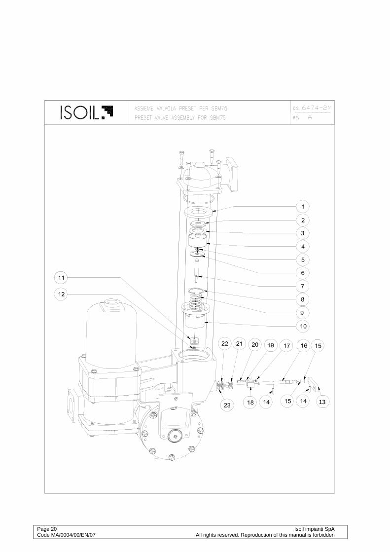
ENCLOSED: Overall dimensions with mechanical counter ......................................... Dwg.4251 Overall dimensions with EM6422 ...................................................... Dwg.5302-3 SBM75 P.D. meter assembly ........................................................... Dwg.6474-M SBM75 P.D. meter assembly with air vent valve ............................ Dwg.6474-1M Preset valve assembly ..................................................................... Dis.6474-2M Vane assembly ..................................................................................... Dwg.6063 Air vent valve ..................................................................................... Dwg.565-M Calibration mechanism ....................................................................... Dwg.672/75 Gearing box for mounting with VEGA counter ....................................... Dwg.3958
ISOIL IMPIANTI updates own products without condition of advance notice. ISOIL IMPIANTI doesn’t take liabilities for use the dates that are modified
Isoil impianti SpA Page 1 All rights reserved. Reproduction of this manual is forbidden. Code MA/0004/00/EN/07
1 Introduction
1.1 Warranty Instruments are guaranteed for twelve months for the date of delivery. Warranty cover only defective parts and faulty workmanship and doesn't cover defects due to wearing, dirt, modification and alteration of the instrument not authorized by Isoil Impianti SpA. Warranty is given free of charge ex our works. Warranty of instruments and accessories not manufactured by Isoil Impianti, will be covered by warranty of the sub supplier. Warranty is valid only if original spares are used and is invalidated in case of improper use or not following the technical specification of the instrument. Only Isoil Impianti SpA has the right to decide if the warranty can be applied. If the purchasing order calls for different warranty conditions, above stated conditions are surpassed.
1.2 Introduction ISOIL positive displacement meters are precision measuring instruments designed for use with a variety of petrochemical products and liquids. Each meter is fully tested and calibrated by factory before dispatch, and a regular service will maintain a high standard of performance and accuracy. P.D. meters must be periodically tested by a calibrating tank, Prover, or Master Meter: if out of accuracy a service is necessary. Experience has shown that mechanical defects are usually caused by the entry of foreign matters into the metering compartment due to inadequate straining facilities in the pipeline. Special tools have been designed to facilitate overhaul operations and their use is recommended.
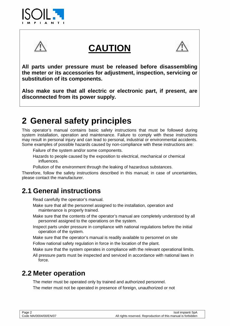
1.3 Working principles Liquid enters the meter through the manifold and causes the rotor to revolve by pressure on the vanes. (fig.1) The proximity of the rotor to the front and rear of the casing forms an efficient seal while the profile of the casing guides the vanes on to the measuring crescent. The seal between vane and body is assured by the combined effects of gravity and centrifugal forces of vanes and it is assured the self-balance of clearances generated by the use too. The rotor spindle extends through a pressure tight seal in the meter front cover into the calibrating mechanism which transmits the rotor movement to the register.
Fig.1
Page 2 Isoil impianti SpA Code MA/0004/00/EN/07 All rights reserved. Reproduction of this manual is forbidden
CAUTION
All parts under pressure must be released before di sassembling the meter or its accessories for adjustment, inspec tion, servicing or substitution of its components. Also make sure that all electric or electronic part , if present, are disconnected from its power supply.
2 General safety principles This operator’s manual contains basic safety instructions that must be followed during system installation, operation and maintenance. Failure to comply with these instructions may result in personal injury and can lead to personal, industrial or environmental accidents. Some examples of possible hazards caused by non-compliance with these instructions are:
Failure of the system and/or some components. Hazards to people caused by the exposition to electrical, mechanical or chemical
influences. Pollution of the environment through the leaking of hazardous substances.
Therefore, follow the safety instructions described in this manual; in case of uncertainties, please contact the manufacturer.
2.1 General instructions Read carefully the operator’s manual. Make sure that all the personnel assigned to the installation, operation and
maintenance is properly trained. Make sure that the contents of the operator’s manual are completely understood by all
personnel assigned to the operations on the system. Inspect parts under pressure in compliance with national regulations before the initial
operation of the system. Make sure that the operator’s manual is readily available to personnel on site Follow national safety regulation in force in the location of the plant. Make sure that the system operates in compliance with the relevant operational limits. All pressure parts must be inspected and serviced in accordance with national laws in
force.
2.2 Meter operation The meter must be operated only by trained and authorized personnel. The meter must not be operated in presence of foreign, unauthorized or not
Isoil impianti S.p.A. Page 1 All rights reserved. Reproduction of this manual is forbidden. Code MA/0026/00/EN/05
adequately trained personnel. The meter must be used for the purpose it is made for; the manufacturer is not
responsible for any damage deriving from uses outside of the original purposes. The meter must be operated inside the limits fixed by the manufacturer; the
manufacturer is not responsible for any damage deriving from uses outside of the operational limits of the device.
2.3 Instructions for the operator The operator must adhere to safety and accident-prevention standards currently in
force in the country where the device is installed. The operator must not, by his own initiative, carry out any operation that is outside his
competence. The operator must carefully comply with hazard and/or prohibition instructions
contained in this manual. Do not use petrol, solvents or other flammable substances to clean parts. Use only
approved commercial solvents that are non-flammable and non-toxic.
2.4 Servicing instructions Read carefully the rating plates on the individual equipment Never carry out any maintenance, servicing or regulation before having closed the root
valve, discharged the pressure from the system and disconnected the power supply to any electrical device (if present), unless explicitly stated otherwise.
All maintenance operations, either ordinary or extraordinary, must be done by authorised and trained personnel
The maintenance operator must wear clothes adequate to the working environment and to the situation; in particular, loose or voluminous clothes, chains, bracelets, rings, earrings or anything that might get caught in the mechanical parts of the system should be avoided
The maintenance operator must wear adequate protective devices in accordance with safety and accident-prevention regulations
In explosive environments use only antisparking equipment If the meter is connected to any electric or electronic equipment, disconnect all of them
from the power supply before doing any servicing or regulation operation, unless explicitly stated otherwise in the manual
2.5 Operating precautions The meter must be calibrated following the instructions reported into the operator's
manual and in what stated into the Manual of Petroleum Measurement Standards (API) with particular attention to the following chapters:
Chapter 4: proving systems Chapter 5: metering Chapter 6: metering assemblies Chapter 11 section 2.3: water calibration of volumetric provers Chapter 12 section 2: calculation of petroleum quantities
The meter must always remain full of product; to achieve this, it is suggested to install the meter so that it remains below the main line.
The line upstream the meter must be kept full of product to avoid that some air enters the meter.
Each meter must be adjusted following the instructions supplied in the operator’s

Page 2 Isoil impianti SpA Code MA/0004/00/EN/07 All rights reserved. Reproduction of this manual is forbidden
manual. Follow the recommendations of the manufacturer when installing pumps. Pay particular
attention to factors such as the use of foot valves, inlet pipes dimension and conformity with NPSH when there are suction pumps. Follow the recommendations of the manufacturer to minimize the problems due to air and vapors.
For flashing liquids (quick gasification of the liquid) or easily vaporizing liquids at high environmental temperatures, e.g. light hydrocarbon, it is advisable the use of submerged aspirations and pipes larger than the nominal dimension of the pump.
Thermal expansions that generate overpressures can easily damage the meters and the systems in general. Put safety valves for overpressure in every section that can be closed through regulation or isolation valves.

Isoil impianti S.p.A. Page 3 All rights reserved. Reproduction of this manual is forbidden. Code MA/0026/00/EN/05
3 Installation
3.1 Precautions The installation of the meter counter does not require any special procedure; just pay attention to the following points:
• The meter counter must be installed horizontally; for other applications a vertical arrangement is provided. In both cases the rotor axis must be kept horizontal.
• All the meter’s openings are protected with covers when shipped; those must not be removed until the meter is installed on the piping
• Before the installation of the meter, it's suggested to clean thoroughly the piping to remove dirt, crusts and other foreign particles.
• Piping should not exercise strain on the meter. The meter is designed for overhang and supports should be provided only on the adjacent pipes.
• Leave space enough around the meter to ease access for adjustment, servicing and disassembly. The counter, if present, must be easily readable.
• The meter must always remain full of product; it's suggested to install the meter so that it remains always under the main line.
• The line upstream the meter must always remain full of product to avoid that air enters the meter's measure chamber; if the pipe arrangement allows reversal flow, a non-return valve must be installed.
• Flow through the meter must be regular and uniform; pulsating and irregular flows must be avoided.
• It is recommended to install flow limiting valves downstream of the meter if the flow rate can reach values higher than the maximum allowed for the meter.
• If the line pressure can reach values higher than the maximum allowed, automatic safety valves must be installed in adequate places.
• To protect meter from damages due to foreign particles in the liquid, a suitable strainer with a correct mesh number (40 mesh for oil, 60 mesh for diesel oil, 100 mesh for
Page 4 Isoil impianti SpA Code MA/0004/00/EN/07 All rights reserved. Reproduction of this manual is forbidden
gasoline) must be installed upstream the meter.
• In case the rate of flow through the installation exceeds the meter maximum rated capacity, it is advisable to use a flow limiting valve, which must be installed downstream the same meter.
• Water must not flow through the meter.
• Meters must be installed in such a way that air or vapour do not enter through the liquid under measurement. It is always suggested to install an air separator just upstream the meter.
• To avoid hammer shocks which may strongly damages the meter, it is not advisable to install upstream or downstream the meter any quick closing valves.
• It is recommended to install root valves at the inlet and outlet to ease servicing operations and isolation of the meter.
3.2 Start-up precautions • Before proceeding with the start-up make sure that:
- The meter is adequately fixed. - All the connections are tightened. - Air is bled from the pipes.
• If a calibration mechanism is associated with the meter, before the start-up it must be filled with lubricating oil.
• Vent out all the air eventually present in the line.
• When the meter is operated for the first time, fill it slowly with the operating fluid by following this procedure:
- Open slowly the upstream isolation meter or fill the meter by gravity. - Open slowly the downstream isolation meter letting the flow rate rise smoothly to
the operating value.
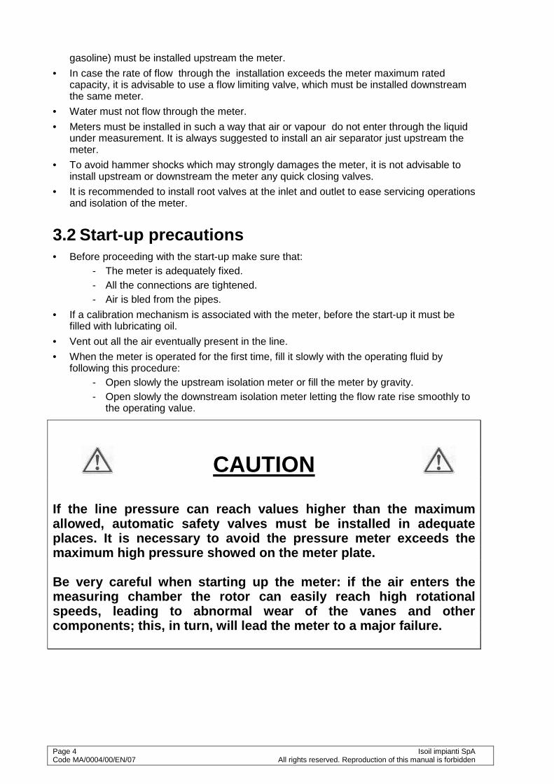
CAUTION
If the line pressure can reach values higher than t he maximum allowed, automatic safety valves must be installed in adequate places. It is necessary to avoid the pressure meter exceeds the maximum high pressure showed on the meter plate. Be very careful when starting up the meter: if the air enters the measuring chamber the rotor can easily reach high r otational speeds, leading to abnormal wear of the vanes and o ther components; this, in turn, will lead the meter to a major failure.
Isoil impianti S.p.A. Page 5 All rights reserved. Reproduction of this manual is forbidden. Code MA/0026/00/EN/05
CAUTION
All parts under pressure must be released before di sassembling the meter or its accessories for adjustment, inspec tion, servicing or substitution of its components. Also make sure that all electric or electronic part , if present, are disconnected from its power supply.
4 Maintenance Before removing the flow meter from the pipeline for repairs, it is recommended that the possible causes and corrective actions are noted with the help of Fault Diagnosis Chart given in this manual. Note that certain components in the flow meter assembly are not interchangeable. Therefore, if more that one flow meter is dismantled, it is recommended that each flow meter is dismantled independently.
CAUTION: Be very careful when you start up the meter after maintenance: if the air enters the measuring chamber the rotor can easily reach high rotational speeds, leading to abnormal wear of the vanes and other components; this, in turn, will lead the meter to a major failure. See chap.3.2 for start-up precautions.
4.1 Disassembly The flow meter may be considered as two main assemblies: the measuring chamber and the calibrating mechanism. To separate these two assemblies from each other, remove the screws securing the calibrating mechanism on the flow meter body.
CAUTION: Before dismantling the meter for maintenance release pressure from the line and drain all the fluid inside the meter through the draining hole below the meter.
Proceed then with the maintenance of the faulty part.
4.1.1 Main components disassembling 1. To ensure stability during the dismounting, it is advisable to use our "Ring Support tool"
(see special tool). 2. Remove the sealings and the screws of the counter, unscrew the screws fixing the
calibrating mechanism and after the removal of the transmission spindle, take off the transmission spindle pin.
3. Remove all nuts, bolts and washers of the front cover. 4. Remove the front cover using the "Cover Removal Tool" (see special tool).The shims
between cover and rotor are not interchangeable, they must be placed in their original position.
5. Remove the rotor group by using the "Rotor removal and turning tool" (see special tool).
Page 6 Isoil impianti SpA Code MA/0004/00/EN/07 All rights reserved. Reproduction of this manual is forbidden
6. Extract the rotor paying attention to use the free hand to guide the rotor and control the lateral vanes movement.
4.1.2 Rotor disassembling
NOTE: Never remove the vanes unless they are damaged. If it is necessary to remove the vanes, before proceeding mark the position of the four vanes that correspond with the position in the rotor: that will ease the reassambly procedure. Vanes are not interchangeable and, if they can be reused, they must be placed in their original position.
See dwg.6063 for disassembling the vanes
• Remove the split pin placed.
• Remove the vane.
• Remove the remaining vane-rods assembly.
CAUTION: Don't remove or loosen the the vanes adjusting nuts, since that would vary the clearance between the vanes and the measuring chamber, causing loss of performance and/or meter failure.
4.2 Assembly Before assembly, clean and inspect all parts for any visual damage. Ensure that all o-ring grooves are clean and undamaged. Examine the O-Rings and ensure that they are not damaged or swollen, replace them if necessary. Examine graphite bushes on rotor assembly for free rotation and play, replace them if either is apparent. Examine each vane assembly for damage or wear, replace vane(s) if either is apparent. Examine gland seal rings in rotor assembly for damage or wear and replace if either is apparent. The assembly procedure is the reversal of the dismantling procedure; only for installation of the internal body special precautions should be taken to match the centering cap of the external body's front cover.
4.3 Calibrating mechanism (only for mechanical counter)
The calibrating mechanism comprises a train of gears which transmit movement of the rotor to the counter. Operational failures of the mechanism are rare and they generally regard the breaking of tension pin, due to an excessive strain. (see dwg.672) It is recommended to repair without varying the calibrating adjustment.
CAUTION: do not remove the shimming washers between the frame and the bearing of the mechanism box.
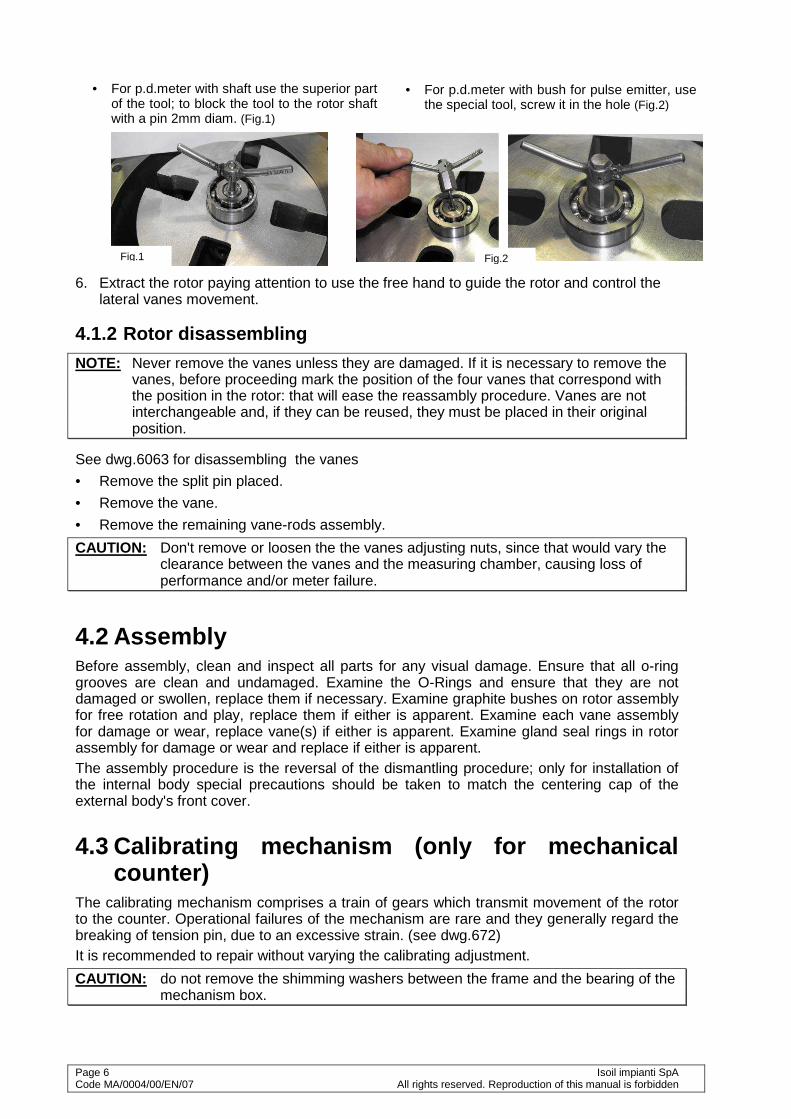
• For p.d.meter with bush for pulse emitter, use the special tool, screw it in the hole (Fig.2)
• For p.d.meter with shaft use the superior part of the tool; to block the tool to the rotor shaft with a pin 2mm diam. (Fig.1)
Fig.1 Fig.2
Isoil impianti S.p.A. Page 7 All rights reserved. Reproduction of this manual is forbidden. Code MA/0026/00/EN/05
This chapter only applies for mechanical counter; for the calibration of the meters with electronic counter please refer to the specific manual.
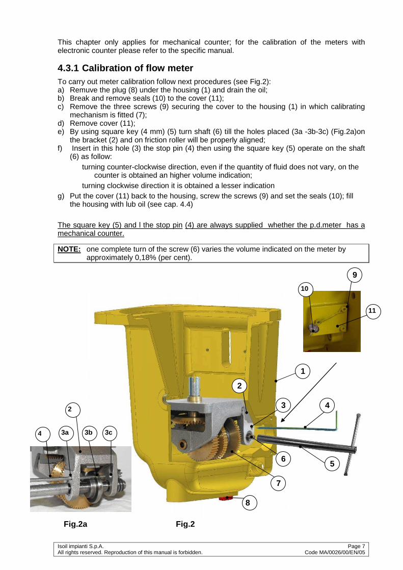
4.3.1 Calibration of flow meter To carry out meter calibration follow next procedures (see Fig.2): a) Remuve the plug (8) under the housing (1) and drain the oil; b) Break and remove seals (10) to the cover (11); c) Remove the three screws (9) securing the cover to the housing (1) in which calibrating
mechanism is fitted (7); d) Remove cover (11); e) By using square key (4 mm) (5) turn shaft (6) till the holes placed (3a -3b-3c) (Fig.2a)on
the bracket (2) and on friction roller will be properly aligned; f) Insert in this hole (3) the stop pin (4) then using the square key (5) operate on the shaft
(6) as follow: turning counter-clockwise direction, even if the quantity of fluid does not vary, on the
counter is obtained an higher volume indication; turning clockwise direction it is obtained a lesser indication
g) Put the cover (11) back to the housing, screw the screws (9) and set the seals (10); fill the housing with lub oil (see cap. 4.4)
The square key (5) and l the stop pin (4) are always supplied whether the p.d.meter has a mechanical counter.
NOTE: one complete turn of the screw (6) varies the volume indicated on the meter by approximately 0,18% (per cent).
Fig.2
2
6
8
7
4
5
3
1
9
10
11
4 3a 3b 3c
2
Fig.2a

Page 8 Isoil impianti SpA Code MA/0004/00/EN/07 All rights reserved. Reproduction of this manual is forbidden
4.4 Suggested lubricating oil for calibrating mechanism
To allow proper lubrication of the gear wheels on the housing is essential to fill the box with lubricating oil, using the black plug on the side of the box. Make sure that the level oil upper the sight glass. In the Table 1 you can choose the lubricating oil if you know the using temperature The oil is suggested by ISOIL, for standard application is SAE10, for a range temperature (from –10° to +60°C); to avoid ice forming in win tertime, add two spoons of car antifreeze.
4.5 Tests after overhaul After overhaul the p.d. meters must be tested with suitable proving systems. Error between the value stated by the p.d.meter counter and the value stated by the proving device is calculated as below: Example: Measured by the meter Measured by the proving tank Error (%) 1000 l 1003 l -0,3% 1000 l 997 l +0,3% The formula is:
100%0
0 ⋅−=V
VVE
V= Measured by the meter V0= Measured by the proving tank
Oli consigliati al variare delle temperature estern e
-60 -40 -20 0 20 40 60 80 100 120 140
SAE 0W
SAE 10W
SAE 10
SAE 10W-40
SAE 15W-40
SAE 10W-60
SAE 5W-30
SAE 0W-30
T°C

Isoil impianti S.p.A. Page 9 All rights reserved. Reproduction of this manual is forbidden. Code MA/0026/00/EN/05
4.6 Strainer/air separator
4.6.1 Strainer A clean strainer is fundamental for the correct operation of the system; a dirt strainer would create an excessive pressure drop, leading to the failure of the basket and thus letting dirt, crusts and other harmful elements to flow into the fluid. If possible, check regularly the pressure drop between the inlet and the outlet of the strainer; the maximum allowed pressure drop is 130 kPa. For a correct servicing of the basket, follow the procedure described below (dwg6474/1M):
• Discharge the pressure from the system and close the valves at the inlet and outlet
• Discharge the liquid inside the strainer air separator through the draining outlet on the bottom of the strainer
• Remove the cap
• Remove the basket and clean it thoroughly with a jet directed from inside to the outside; if possible, use a water cleaning machine
• Check accurately that the gasket is intact; if it is found to be damaged, replace with another one with the same filtering grade:
For oils with viscosity up to 20°E(150cSt): 40 mesh (433 micron) For diesel oils: 60 mesh (247 micron) For gasoline or water: 100 mesh (153 micron)
• Put again the wire gauze in place, close the cover and the drain valve. It's suggested to replace the gaskets between the strainer body and the cover each time the strainer air separator is disassembled.
4.6.2 Air vent valve Follow the istructions below for the servicing of the air vent valve:
• Discharge the pressure from the system and close the valves at the inlet and outlet
• Discharge the liquid inside the strainer air separator through the draining outlet
• Inspect the air vent valve, checking that it works properly and its part aren't damaged
• Close the draining valve and restore the operating conditions
4.7 Extraordinary maintenance The user must define a maintenance scheduling table according to the fluid utilised, the operational conditions, the estimated/real workloads and the environmental conditions. For all extraordinary maintenance needed after a failure and/or the rising of a fault that compromises the normal operation of the system, please contact Isoil Impianti SpA Customer Care.
4.8 Storing if after a working period it is foreseen to stop the meter for a long time, drain the meter
and its accessories; If the meter or the equipment of the system are not immediately used, or if it is
withdrawn from service and stored, it is important to follow next instructions : fill the meter and its accessories with clean kerosene or lubricated oil and close its

Page 10 Isoil impianti SpA Code MA/0004/00/EN/07 All rights reserved. Reproduction of this manual is forbidden
ends with blind flanges; fill the carter containing the calibrating mechanism with oil till the sight glass is
reached adequately protect counters against rain and dust, with damp-proof caps
4.9 Spare parts For a correct meter maintenance use only original spare parts from Isoil Impianti S.p.A. . Isoil Impianti S.p.A. is not responsible for any problem that can result from the use of non original spare parts.
4.10 Maintenance schedule Task Monthly 6 Months 12 Months 24 Months
Visual inspection of manifold and meter body; check for leaks
X
Inspection of the meter; check for internal part status: vanes, rotor, measure chamber, o-rings; check for wear or damage.
X
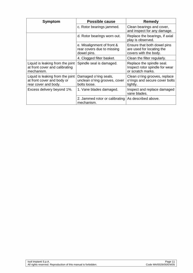
4.11 Troubleshooting Symptom Possible cause Remedy
Liquid passing with normal flow rate but counter fails to register.
1. Defective counter. Remove and check the counter by rotating bottom coupling. In case of any problem in the counter, contact the factory.
2. Drive from the rotor fails to reach the counter, due to sheared pins in the calibrating mechanism.
Check cross pins fitted on all gears in the calibrating mechanism.
No liquid passing through. 1. Defective counter. Remove and inspect the counter for free movement.
2. Jammed calibrating mechanism.
Remove and inspect the calibrating mechanism. Identify the source of friction and replace relevant parts.
3. Jammed rotor assembly. Dismantle meter assembly. Inspect front & rear covers and rotor for scoring marks. Inspect vanes and bearings for damage.
Causes of rotor jamming : a. Solid particles trapped on
rotor surface. Clean the rotor surfaces.
b. Incorrect adjustment of rotor end clearance due to loose or defective bearing adjuster.
Check setting of bearing adjuster. Clean and inspect the bearing adjuster.
Isoil impianti S.p.A. Page 11 All rights reserved. Reproduction of this manual is forbidden. Code MA/0026/00/EN/05
Symptom Possible cause Remedy c. Rotor bearings jammed. Clean bearings and cover,
and inspect for any damage. d. Rotor bearings worn out. Replace the bearings, if axial
play is observed. e. Misalignment of front &
rear covers due to missing dowel pins.
Ensure that both dowel pins are used for locating the covers with the body.
4. Clogged filter basket. Clean the filter regularly. Liquid is leaking from the joint at front cover and calibrating mechanism.
Spindle seal is damaged. Replace the spindle seal. Inspect rotor spindle for wear or scratch marks.
Liquid is leaking from the joint at front cover and body or rear cover and body.
Damaged o’ring seals, unclean o’ring grooves, cover bolts loose.
Clean o’ring grooves, replace o’rings and secure cover bolts tightly.
Excess delivery beyond 1%. 1. Vane blades damaged. Inspect and replace damaged vane blades.
2. Jammed rotor or calibrating mechanism.
As described above.
Page 12 Isoil impianti SpA Code MA/0004/00/EN/07 All rights reserved. Reproduction of this manual is forbidden
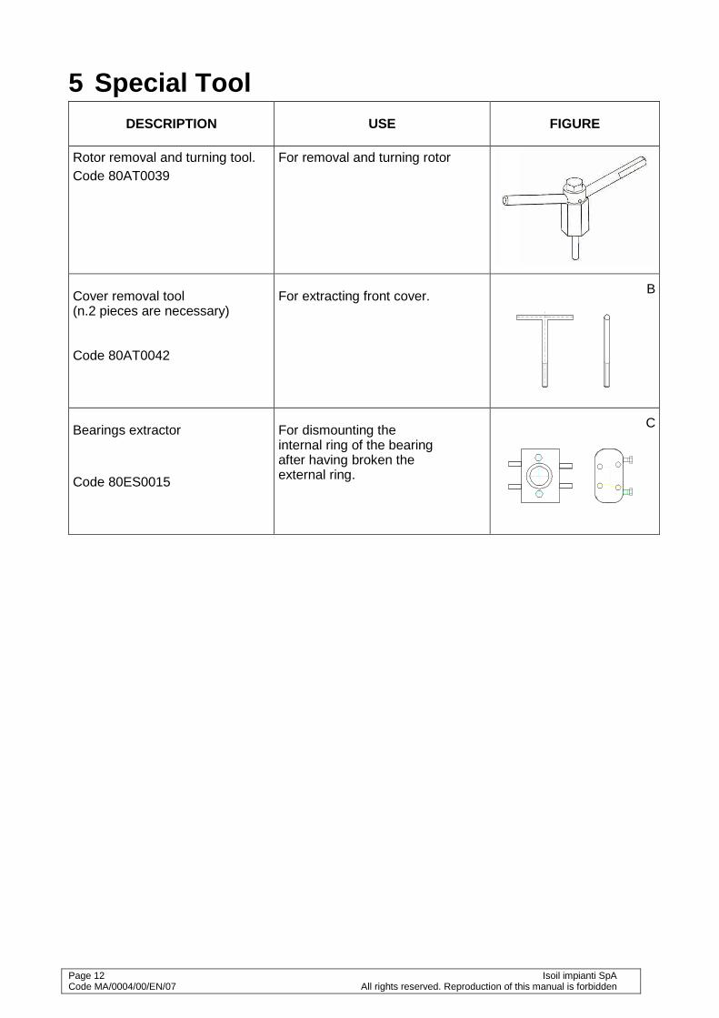
5 Special Tool DESCRIPTION USE FIGURE
Rotor removal and turning tool. Code 80AT0039
For removal and turning rotor
Cover removal tool (n.2 pieces are necessary) Code 80AT0042
For extracting front cover. B
Bearings extractor
Code 80ES0015
For dismounting the internal ring of the bearing after having broken the external ring.
C
Isoil impianti S.p.A. Page 13 All rights reserved. Reproduction of this manual is forbidden. Code MA/0026/00/EN/05
6 Technical data • Maximum working pressure ................................................................................ 1000 kPa
• Working temperature ................................................................................... -10°C ÷ +50°C
• Maximum flow rate ................................................................................................. 500 lpm The value reproduced in label can change as regards to those shown in the manual

Page 14 Isoil impianti SpA Code MA/0004/00/EN/07 All rights reserved. Reproduction of this manual is forbidden

Isoil impianti S.p.A. Page 15 All rights reserved. Reproduction of this manual is forbidden. Code MA/0026/00/EN/05
1
1
2
2
3
3
4
4
5
5
6
6
A A
B B
C C
D D
// /
67 90
67
90
Ø11
FLANGE QUADRE PN50DN50 SQUARE FLANGES
~295
509
191
384
100
SPAZIO PER ESTRAZIONE CESTO FILTROCLEARANCE FOR BASKET STRAINER REMOVAL
554
Page 16
Isoil impianti S
pA
Code M
A/0004/00/E
N/07
All rights reserved. R
eproduction of this manual is forbidden
DIS.
FOGLIO1 DI 1
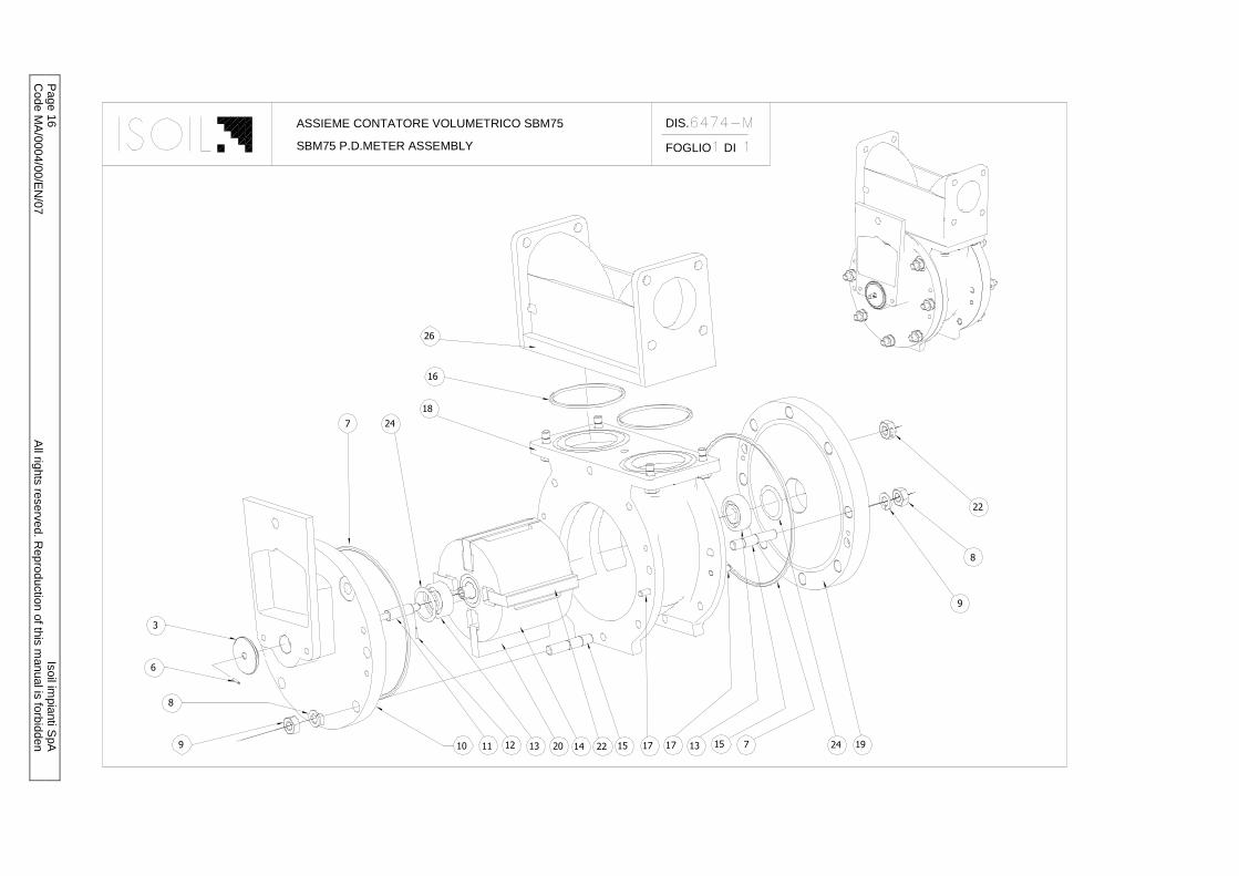
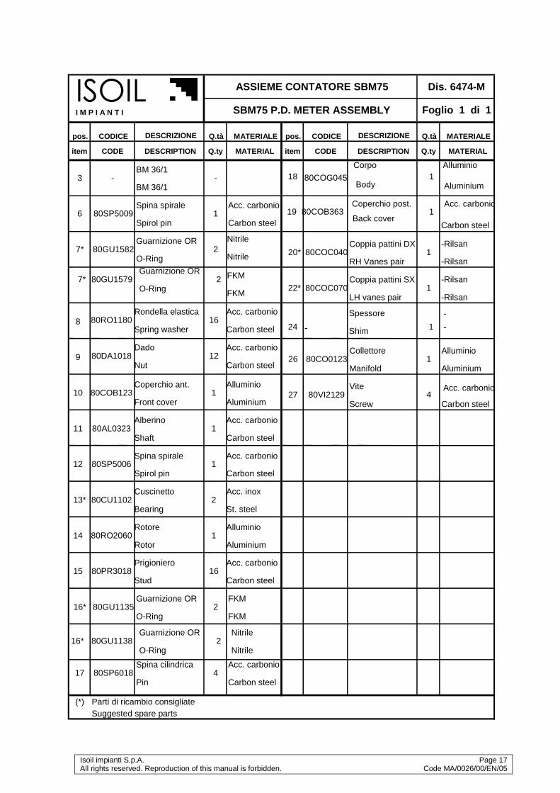
6474-MASSIEME CONTATORE VOLUMETRICO SBM75
SBM75 P.D.METER ASSEMBLY
6
8
9 10 11 12 13 20 14 22 15 17 17 13 15 7 24 19
9
8
22
7 24
18
16
26
3
Isoil impianti S.p.A. Page 17 All rights reserved. Reproduction of this manual is forbidden. Code MA/0026/00/EN/05
pos. CODICE DESCRIZIONE Q.tà MATERIALE pos. CODICE DESCRIZIONE Q.tà MATERIALE
item CODE DESCRIPTION Q.ty MATERIAL item CODE DESCRIPTION Q .ty MATERIAL
BM 36/1
Coppia pattini DX -Rilsan
BM 36/1
RH Vanes pair -Rilsan
Spina spirale Acc. carbonio
Coppia pattini SX -Rilsan
Spirol pin Carbon steel
LH vanes pair -Rilsan
Guarnizione OR
FKM
Collettore Alluminio
O-Ring
FKM
Manifold Aluminium
Dado Acc. carbonio
Vite Acc. carbonio
Nut Carbon steel
Screw Carbon steel
Rondella elastica Acc. carbonio
Spring washer Carbon steel
Coperchio ant. Alluminio
Front cover Aluminium
Alberino Acc. carbonio
Shaft Carbon steel
Spina spirale Acc. carbonio
Spirol pin Carbon steel
Cuscinetto Acc. inox
Bearing St. steel
Rotore Alluminio
Rotor Aluminium
Prigioniero Acc. carbonio
Stud Carbon steel
Guarnizione OR FKM
O-Ring FKM
Spina cilindrica Acc. carbonio
Pin Carbon steel
(*) Parti di ricambio consigliateSuggested spare parts
120*
22* 80COC070 1
26 80CO0123
27
1
80VI2129 4
15
80CU1102 2
14 80RO2060 1
13*
80PR3018 16
17 80SP6018
16* 80GU1135 2
4
80AL0323 1
12 80SP5006 1
11
10 80COB123 1
9
80RO1180 16
7*
8
80DA1018
1
2
12
80SP5009
80GU1582
6
Dis. 6474-M
Foglio 1 di 1
3 - -
ASSIEME CONTATORE SBM75
SBM75 P.D. METER ASSEMBLY
80COC040
ISOILI M P I A N T I
-
-24 - 1
Spessore
Shim
Corpo Alluminio
Body Aluminium
Coperchio post. Acc. carbonio
Back coverCarbon steel
19 80COB363 1
80COG045 118
Guarnizione OR Nitrile
O-Ring Nitrile16* 80GU1138 2
Guarnizione OR
Nitrile
O-Ring
Nitrile
7* 280GU15799

Page 18 Isoil impianti SpA Code MA/0004/00/EN/07 All rights reserved. Reproduction of this manual is forbidden
1
2
3
11
15
16
18
20
21
22
24
25
26
28
27
29
29
29
30
25
32
35
6
8
7
4
5
10
9
23
34
27
2833
12
28
27
31

Isoil impianti S.p.A. Page 19 All rights reserved. Reproduction of this manual is forbidden. Code MA/0026/00/EN/05
Foglio 1 di 1
pos . N° CODICE DESCRIZIONE Q.tà M ATERIALE pos. N° CODICE DESCRIZIONE Q.tà M ATERIALE
i tem N° CODE DESCRIPTION Q.ty M ATERIAL i tem N° CODE DESCRIPTION Q.ty M ATERIAL
1 80COG009Corpo collettore Body 1
Alluminio Aluminium 24* 80GU0172
Guarniz ione OR O-ring 1
Nitrile Nitrile
2 80COG219Corpo f iltro Strainer body
1Alluminio Aluminium
24* 80GU0171Guarniz ione OR O-ring
1FKM FKM
3 80GO1009Gomito Elbow
1Alluminio Alluminium
25 80VI4201Vite Srew
4Acc. Carbonio Carbon steel
4* 80GU1360Guarnizione OR O-ring
1Nitrile Nitrile
26 80RO1207Rondella elastica Spring washer
4Acc. Carbonio Carbon steel
4* 80GU1357Guarnizione OR O-ring
1FKM FKM
27 80VI2192Vite Srew
12Acc. Carbonio Carbon steel
5 80PI1003Piattello Plate
1Acc. Carbonio Carbon steel
28 80RO1183Rondella elastica Spring washer
12Acc. Carbonio Carbon steel
6 80AL0153Alberino Shaft
1Acc. Inox St. steel
29* 80GU1582Guarniz ione OR O-ring
3Nitrile Nitrile
7 80VI8111Vite Srew
1Acc. Carbonio Carbon steel
29* 80GU1579Guarniz ione OR O-ring
3FKM FKM
8 80SP5009Spina spirale Spirol spin
1Acc. al carb. Carbon steel
30 80TA1090Tappo Pulg
1Acc. Inox St. steel
9 80AN1018Anello Ring
1Alluminio Aluminium
31 80VA4021Valvola Degasatrice Air vent valve
1- -
10 80MO0129Molla Spring
1Acc. Inox St. steel
32 80VI4267Vite Srew
4Acc. Carbonio Carbon steel
11* 80GU1501Guarnizione OR O-ring
1Nitrile Nitrile
33 80RO1180Rondella Washer
4Acc. Carbonio Carbon steel
11* 80GU1498Guarnizione OR O-ring
1FKM FKM
34* 80CE2075Cesto f iltro 100mesh Strain. b asket 100mesh
1Acc. Inox St. steel
12 80BO1039Boccola O-ring
1Ottone Brass
34* 80CE2069Cesto f iltro 60 mesh Strain. b asket 60mesh
1Acc. Inox St. steel
15 80VI8051Vite Srew
4Acc. Carbonio Carbon steel
34* 80CE2066Cesto f iltro 40 mesh Strain. b asket 40 mesh
1Acc. Inox St. steel
16 80PI1045Piattello Plate
1Ottone Brass
35 80GU0024Guarniz ione Gasket
1Nitrile Nitrile
18* 80GU1195Guarnizione OR O-ring 1
Nitrile Nitrile
18* 80GU1192Guarnizione OR O-ring
1FKM FKM
20 80COB297Coperchio f iltro Strainer cover
1Alluminio Aluminium
21 80DI0000Diaf ramma Diaphragm
1Acc. al carb. Carbon steel
22 80CA0006Calotta Cap
1Alluminio Aluminium
23 80PI7012Pistone Piston
1Bronzo Bronze *
T-3291-2.XLS
Parti di ricambio consigliate / Suggested spare par ts
Dis. 6474-1MASSIEME CONTATORE SBM 75
SBM 75 P.D. M ETER ASSEM BLYISO IL I M P I A N T I
Page 20 Isoil impianti SpA Code MA/0004/00/EN/07 All rights reserved. Reproduction of this manual is forbidden
23 13
Isoil impianti S.p.A. Page 21 All rights reserved. Reproduction of this manual is forbidden. Code MA/0026/00/EN/05
Foglio 1 di 1
pos. N° CODICE DESCRIZIONE Q.tà MATERIALE pos. N° CODICE DESCRIZIONE Q.tà MATERIALE
item N° CODE DESCRIPTION Q.ty MATERIAL item N° CODE DESCRIPTION Q.ty MATERIAL
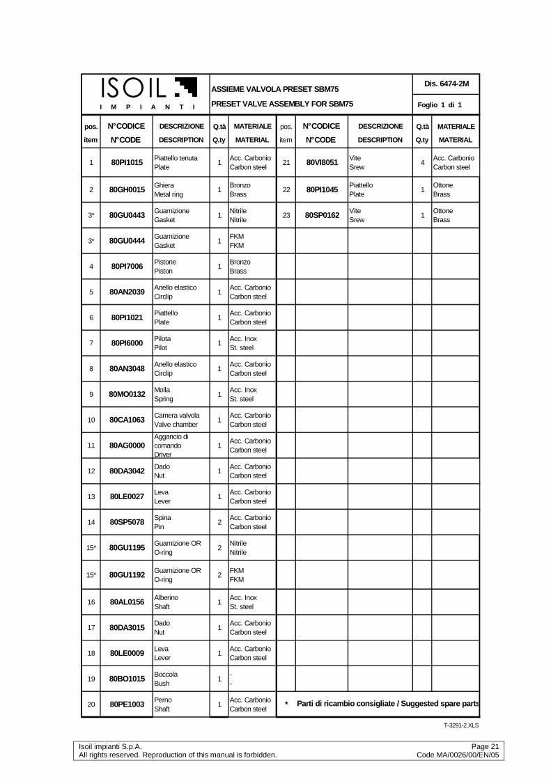
1 80PI1015 Piattello tenuta Plate
1Acc. Carbonio Carbon steel
21 80VI8051 Vite Srew
4Acc. Carbonio Carbon steel
2 80GH0015 Ghiera Metal ring
1Bronzo Brass
22 80PI1045Piattello Plate
1Ottone Brass
3* 80GU0443 Guarnizione Gasket
1Nitrile Nitrile
23 80SP0162 Vite Srew
1Ottone Brass
3* 80GU0444 Guarnizione Gasket
1FKM FKM
4 80PI7006 Pistone Piston
1Bronzo Brass
5 80AN2039 Anello elastico Circlip
1Acc. Carbonio Carbon steel
6 80PI1021Piattello Plate
1Acc. Carbonio Carbon steel
7 80PI6000 Pilota Pilot
1Acc. Inox St. steel
8 80AN3048 Anello elastico Circlip
1Acc. Carbonio Carbon steel
9 80MO0132 Molla Spring
1Acc. Inox St. steel
10 80CA1063 Camera valvola Valve chamber
1Acc. Carbonio Carbon steel
11 80AG0000Aggancio di comando Driver
1Acc. Carbonio Carbon steel
12 80DA3042 Dado Nut
1Acc. Carbonio Carbon steel
13 80LE0027 Leva Lever
1Acc. Carbonio Carbon steel
14 80SP5078 Spina Pin
2Acc. Carbonio Carbon steel
15* 80GU1195 Guarnizione OR O-ring
2Nitrile Nitrile
15* 80GU1192 Guarnizione OR O-ring
2FKM FKM
16 80AL0156 Alberino Shaft
1Acc. Inox St. steel
17 80DA3015Dado Nut
1Acc. Carbonio Carbon steel
18 80LE0009 Leva Lever
1Acc. Carbonio Carbon steel
19 80BO1015 Boccola Bush
1- -
20 80PE1003 Perno Shaft
1Acc. Carbonio Carbon steel
*
T-3291-2.XLS
Parti di ricambio consigliate / Suggested spare par ts
Dis. 6474-2MASSIEME VALVOLA PRESET SBM75
PRESET VALVE ASSEMBLY FOR SBM75ISOIL I M P I A N T I

Page 22 Isoil impianti SpA Code MA/0004/00/EN/07 All rights reserved. Reproduction of this manual is forbidden
ISOIL IMPIANTI S.p.A.
MI
IM
IPPPPI
MI
IMM
IIM
IPPPPI
MI
IM
AN
IN
IT
AT
AATTI
NI
NNI
NI
TTAA
TA
TI
NI
NA

Isoil impianti S.p.A. Page 23 All rights reserved. Reproduction of this manual is forbidden. Code MA/0026/00/EN/05
Page 24 Isoil impianti SpA Code MA/0004/00/EN/07 All rights reserved. Reproduction of this manual is forbidden
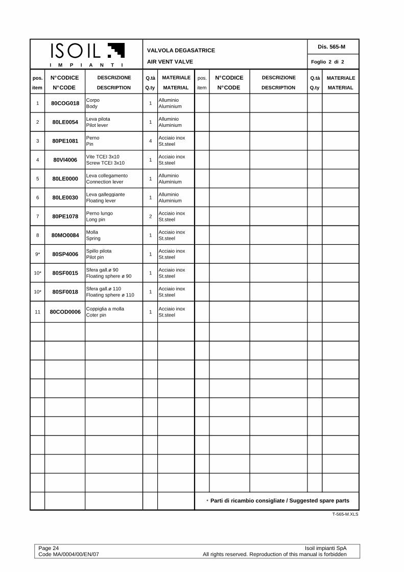
VALVOLA DEGASATRICE Dis. 565-M
AIR VENT VALVE Foglio 2 di 2
pos. N° CODICE DESCRIZIONE Q.tà MATERIALE pos. N° CODICE DESCRIZIONE Q.tà MATERIALE
item N° CODE DESCRIPTION Q.ty MATERIAL item N° CODE DESCRIPTION Q.ty MATERIAL
1 80COG018Corpo Body
1Alluminio Aluminium
2 80LE0054Leva pilota Pilot lever
1Alluminio Aluminium
3 80PE1081Perno Pin
4Acciaio inox St.steel
4 80VI4006Vite TCEI 3x10 Screw TCEI 3x10
1Acciaio inox St.steel
5 80LE0000Leva collegamento Connection lever
1Alluminio Aluminium
6 80LE0030Leva galleggiante Floating lever
1Alluminio Aluminium
7 80PE1078Perno lungo Long pin
2Acciaio inox St.steel
8 80MO0084Molla Spring
1Acciaio inox St.steel
9* 80SP4006Spillo pilota Pilot pin
1Acciaio inox St.steel
10* 80SF0015Sfera gall.ø 90 Floating sphere ø 90
1Acciaio inox St.steel
10* 80SF0018Sfera gall.ø 110 Floating sphere ø 110
1Acciaio inox St.steel
11 80COD0006 Coppiglia a molla Coter pin
1Acciaio inox St.steel
*
T-565-M.XLS
Parti di ricambio consigliate / Suggested spare parts
ISO IL I M P I A N T I

Isoil impianti S.p.A. Page 25 All rights reserved. Reproduction of this manual is forbidden. Code MA/0026/00/EN/05

Page 26 Isoil impianti SpA Code MA/0004/00/EN/07 All rights reserved. Reproduction of this manual is forbidden
MECCANISMO DI CALIBRAZIONE SBM 75 MK2 E SBM 75/ AL
CALIBRATION MECHANISM SBM 75 MK2 AND SBM 75/AL
pos. N° CODICE DESCRIZIONE Q.tà MATERIALE pos. N° CODICE D ESCRIZIONE Q.tà MATERIALE
item N° CODE DESCRIPTION Q.ty MATERIAL item N° CODE DESCRI PTION Q.ty MATERIAL
1 80SC2009Scatola meccanismo Calibr.mechanism box
1Alluminio Aluminium
24 80IN3144Ingranaggio Gear
1Acc.al carb. Carbon Steel
2 80VI2042Vite fissaggio supporto Support screw
4Acc.al carb. Carbon Steel
26 80RO1075Rondella di rasamento Shim washer
2Acc.al carb. Carbon Steel
3 80SV0012Supporto disp.regolaz. Calibr.mech.support
1Alluminio Aluminium
27 80BO1009Boccola autolubrif. Self-lubric. bush
1Bronzo Bronze
4 80AS0027Ass.disco frizione Friction wheel
1Acc.al carb. Carbon Steel
28* 80SP5009Spina spirale Spirol pin
1Acc.al carb. Carbon Steel
5Fornito con pos.4 Supplied with item 4
30 80AL0270Alberino prolunga Extension shaft
1Acc.al carb. Carbon Steel
6* 80AS0129Ass.albero con pign. Shaft with pinion
1Acc.al carb. Carbon Steel
32 80PI5000Pignone conico Bevel pinion
1Acc.al carb. Carbon Steel
7 80AS0258Ass. vite senza fine Worm screw
1Acc.al carb. Carbon Steel
33Viene forn. con pos.17 Supplied with item 17
8*Fornito con pos.7 Supplied with item 7
1 34 80AS0084Ass. alberino/pignone Shaft/gear assembly
1Acciaio inox St. steel
9* 80CU1081Cuscinetti Bearings
2Acciaio inox Stainless steel
35 80IN3162Ingranaggio Gear
1Acc.al carb. Carbon Steel
10 80VI4201Viti Screws
2Acc.al carb. Carbon Steel
36 80AN2024Anello elastico Elastic ring
1Acc.al carb. Carbon Steel
11 80TA1072Tappo scarico Oil discharge plug
1 37Fornito con pos.34 Supplied with item 34
1
12 80TA1015Tappo carico olio Oil charge plug
1 38 80SP5009Spina spirale Spirol pin
3Acc.al carb. Carbon Steel
13 80VI5117Vite Screw
1Acc.al carb. Carbon Steel
39 80IN0006Indicatore livello olio Oil level indicator
1
14 80COB069Coperchio accesso Calibrating cap
1Alluminio Aluminium
40 80MA1012Manicotto per trasmis. Transmission sleeve
1Acc.al carb. Carbon Steel
15 80AN2018Anello elastico Bearing circlip stop
1Acc.al carb. Carbon Steel
41Fornito con pos.6 Supplied with item 6
1
16 80RO1063Rondella rasamento Shim washer
7Acc.al carb. Carbon Steel
42 80SP5006Spina spirale Spirol pin
1Acc.al carb. Carbon Steel
17 80AS0123Assieme ingranaggi Gears assembly
1Acc.al carb. Carbon Steel
43 80RO1078Rondella di rasamento Shim wahser
2Acc.al carb. Carbon Steel
18 80AL0132Alberino Gear pin
1Acc.al carb. Carbon Steel
44* 80GU1243Guarnizione Gasket
1Viton Viton
19 80MO0228Molla spingi disco friz. Friction plate spring
1Acciaio inox St. steel
45 80AN2006Anello elastico Circlip
1Acc.al carb. Carbon Steel
20 80PI1057Piattello per frizione Friction plate
1Acc.al carb. Carbon Steel
46Fornito con pos.17 Supplied with item 17
21 80RO1042Rondella di centraggio Centering washer
1Acc.al carb. Carbon Steel
47 80BO1000Boccola Bush
2Bronzo Bronze
22* 80CU1045Cuscinetto reggispinta Axial bearing
1Acc.al carb. Carbon Steel
48Fornito con pos.17 Supplied with item 17
23 80BO1000Boccola Bush
2Bronzo Bronze
* Parti di ricambio consigliate / Suggested spare parts
Foglio 1 di 2
Dis. 672/75ISO IL I M P I A N T I
Isoil impianti S.p.A. Page 27 All rights reserved. Reproduction of this manual is forbidden. Code MA/0026/00/EN/05
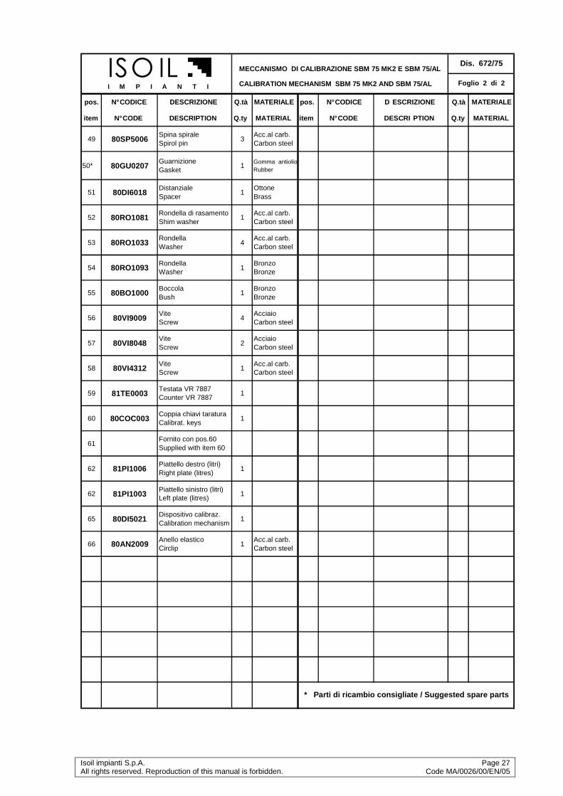
MECCANISMO DI CALIBRAZIONE SBM 75 MK2 E SBM 75/ AL
CALIBRATION MECHANISM SBM 75 MK2 AND SBM 75/AL
pos. N° CODICE DESCRIZIONE Q.tà MATERIALE pos. N° CODICE D ESCRIZIONE Q.tà MATERIALE
item N° CODE DESCRIPTION Q.ty MATERIAL item N° CODE DESCRI PTION Q.ty MATERIAL
49 80SP5006Spina spirale Spirol pin
3Acc.al carb. Carbon steel
50* 80GU0207Guarnizione Gasket
1Gomma antiolio Rubber
51 80DI6018Distanziale Spacer
1Ottone Brass
52 80RO1081Rondella di rasamento Shim washer
1Acc.al carb. Carbon steel
53 80RO1033Rondella Washer
4Acc.al carb. Carbon steel
54 80RO1093Rondella Washer
1Bronzo Bronze
55 80BO1000Boccola Bush
1Bronzo Bronze
56 80VI9009Vite Screw
4Acciaio Carbon steel
57 80VI8048Vite Screw
2Acciaio Carbon steel
58 80VI4312Vite Screw
1Acc.al carb. Carbon steel
59 81TE0003Testata VR 7887 Counter VR 7887
1
60 80COC003Coppia chiavi taratura Calibrat. keys
1
61Fornito con pos.60 Supplied with item 60
62 81PI1006Piattello destro (litri) Right plate (litres)
1
62 81PI1003Piattello sinistro (litri) Left plate (litres)
1
65 80DI5021Dispositivo calibraz. Calibration mechanism
1
66 80AN2009Anello elastico Circlip
1Acc.al carb. Carbon steel
* Parti di ricambio consigliate / Suggested spare parts
Dis. 672/75
Foglio 2 di 2ISO IL I M P I A N T I
Page 28 Isoil impianti SpA Code MA/0004/00/EN/07 All rights reserved. Reproduction of this manual is forbidden

Isoil impianti S.p.A. Page 29 All rights reserved. Reproduction of this manual is forbidden. Code MA/0026/00/EN/05
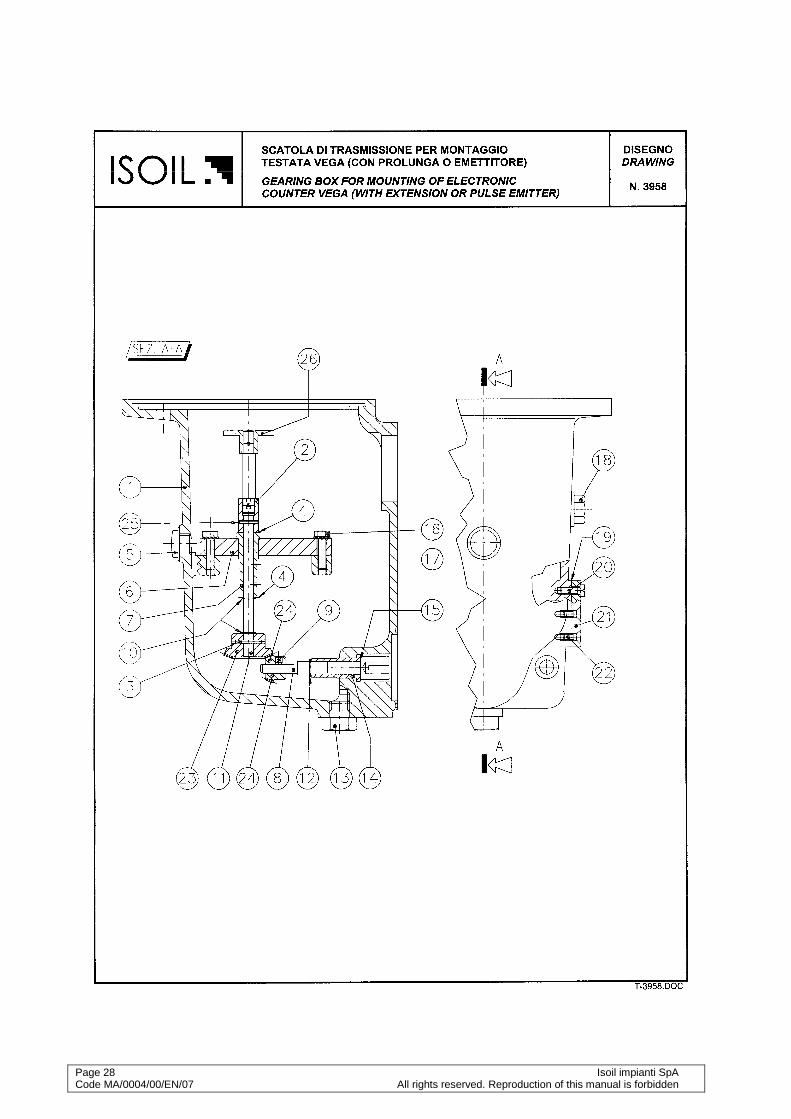
SCATOLA DI TRASMISSIONE PER MONT.TESTATA VEGA Dis. 3958
GEARING BOX FOR ELECTR. COUNTER VEGA MOUNTING Foglio 1 di 1
pos. N° CODICE DESCRIZIONE Q.tà MATERIALE pos. N° CODICE DESCRIZIONE Q.tà MATERIALE
item N° CODE DESCRIPTION Q.ty MATERIAL item N° CODE DESCRIPTION Q.ty MATERIAL
1 80SC2030Scatola meccanismo Mechanism box
1Alluminio Aluminium
24 80IN3276Ingranaggio Gear
1Acc.carbonio Carbon steel
2 80MA1009
Manicotto di trasmissione Transmission coupling
1Acc.carbonio Carbon steel 25 80SP5009
Spina spirale Spirol pin 1
Acc.carbonio Carbon steel
3 80SP5018Spina spirale Spirol pin
1Acc.carbonio Carbon steel
26 80AS0102Trascinatore Entrainer
1Acc.carbonio Carbon steel
4 80RO1078Rondella di rasamento Washer
4Acc.carbonio Carbon steel
5 80IN0006Indicatore livello olio Oil level indicator
1
6 80SU0072Supporto mecc.perVEGA Mech.support for
1Alluminio Aluminium
7 80BO1147Boccola Bush
1Bronzo Bronze
8 80AL0243Alberino Shaft 1
Acc.inox St.steel
9 80GR1093Grano Grain
1Acc.inox St.steel
10 80AN2006Anello elastico Retaining ring
2Acc. al carb. Carbon steel
11 80AL0246Alberino Shaft
1Acc. inox St. steel
12 80AN2000Anello elastico Retaining ring
1Acc. al carb. Carbon steel
13 80TA1072Tappo scarico olio+guarn. Oil discharge plug
1
14 80BO1099Boccola Bush
1Bronzo Bronze
15 80RO1066Rondella di rasamento Washer
2Acc. al carb. Carbon steel
16 80VI2042Vite Screw
4Acc. al carb. Carbon steel
17 80RO1033Rondella dent.esterna Exernal washer
4Acc. al carb. Carbon steel
18 80TA1015Tappo carico olio Oil charge plug
1
19 80GU0207Guarnizione Gasket
1
20 80VI5117Vite Screw
1Acc. al carb. Carbon steel
21 80COB069Coperchio accesso tar. Calibr.inlet cover
1Alluminio Aluminium
22 80VI8048Vite Screw
2Acc. al carb. Carbon steel
23 80IN3279Ingranaggio Gear
1Acc. al carb. Carbon steel
ISOIL I M P I A N T I
Related Documents