SAW sensor read range limitations and perspectives Faiza Nawaz • Varun Jeoti Ó Springer Science+Business Media New York 2014 Abstract Wireless monitoring systems with passive sur- face acoustic wave (SAW) sensors offer novel and prodi- gious perspectives for remote monitoring and control in harsh environments. This paper reviews the working prin- ciple of such passive sensors and their state-of-the-art behavior. All major fields of the SAW sensor require operation over a longer reading range, which is the current limitation, hindering the massive implementation of these passive devices. This foremost limitation of the SAW based sensor system occurs when the reply signal strength at the reader becomes too weak for reliable recognition and identification. SAW sensor network read range limitations and advanced techniques for its enhancement are deliber- ated. Deployment design to maintain the communication reliability and connectivity of the sensor/interrogators network is also discussed. Keywords Surface acoustic wave Wireless sensor network Passive sensor Read range 1 Introduction With the recent advancement in ubiquitous computing, surface acoustic wave (SAW) devices find numerous applications in everyday life, especially in sensor systems, and in identification mechanisms or a combination of both [1, 2]. Implementation of SAW device as a sensor is an upcoming field of interest due to its valuable characteristics of high portability, sensitivity and passive nature. The passive nature of the SAW sensor makes it highly desirable in information and communication technology (ICT) where energy efficiency is always required [3]. Today they are widely used for monitoring temperature [4, 5], pressure [6, 7], chemicals [8] and gas leakage [9, 10] for both indoor and outdoor applications. A radio SAW sensor system usually has an interrogation unit and one or more SAW sensor distributed over an area to be monitored. The request signal is transmitted from the interrogator to the sensor (downlink) while the SAW sensor responds with a back scattered signal (uplink) that is received by the receiver section of the interrogation sys- tem. Up and downlink, the interrogator’s request signal and the sensor’s response, all have to be separated. These radio sensors can be of three categories, based on their source of energy. Active devices; powered by a built in battery, semi active devices; energized by strong radio frequency signal or inductive coupling and passive sensors which uses the mechanism of back scatter without requiring any internal energy storage. Silicon-based Integrated Circuits (ICs) are another popular type of sensors, however SAW based sensors are distinguished from them by the unique piezoelectric crystal effect produced by applying a proper electrical field. The SAW sensor being passive, offers a variety of advantages as compared to IC based sensors. SAW signal has a longer range as it is 100 times smaller than IC’s based signal, and thus, it has better signal penetration, and can be tagged on metals and liquid. The extended reading range of the pas- sive SAW sensors can replace high-cost battery-powered active sensors. In addition, because the substrate materials used in SAW sensor are piezoelectric crystal, they can work at temperatures up to several hundred degrees, can F. Nawaz (&) V. Jeoti Department of Electrical and Electronic Engineering, Universiti Teknologi Petronas, 31750 Tronoh, Perak, Malaysia e-mail: [email protected] V. Jeoti e-mail: [email protected] 123 Wireless Netw DOI 10.1007/s11276-014-0765-3

Welcome message from author
This document is posted to help you gain knowledge. Please leave a comment to let me know what you think about it! Share it to your friends and learn new things together.
Transcript
SAW sensor read range limitations and perspectives
Faiza Nawaz • Varun Jeoti
� Springer Science+Business Media New York 2014
Abstract Wireless monitoring systems with passive sur-
face acoustic wave (SAW) sensors offer novel and prodi-
gious perspectives for remote monitoring and control in
harsh environments. This paper reviews the working prin-
ciple of such passive sensors and their state-of-the-art
behavior. All major fields of the SAW sensor require
operation over a longer reading range, which is the current
limitation, hindering the massive implementation of these
passive devices. This foremost limitation of the SAW
based sensor system occurs when the reply signal strength
at the reader becomes too weak for reliable recognition and
identification. SAW sensor network read range limitations
and advanced techniques for its enhancement are deliber-
ated. Deployment design to maintain the communication
reliability and connectivity of the sensor/interrogators
network is also discussed.
Keywords Surface acoustic wave � Wireless sensor
network � Passive sensor � Read range
1 Introduction
With the recent advancement in ubiquitous computing,
surface acoustic wave (SAW) devices find numerous
applications in everyday life, especially in sensor systems,
and in identification mechanisms or a combination of both
[1, 2]. Implementation of SAW device as a sensor is an
upcoming field of interest due to its valuable characteristics
of high portability, sensitivity and passive nature. The
passive nature of the SAW sensor makes it highly desirable
in information and communication technology (ICT) where
energy efficiency is always required [3]. Today they are
widely used for monitoring temperature [4, 5], pressure [6,
7], chemicals [8] and gas leakage [9, 10] for both indoor
and outdoor applications.
A radio SAW sensor system usually has an interrogation
unit and one or more SAW sensor distributed over an area
to be monitored. The request signal is transmitted from the
interrogator to the sensor (downlink) while the SAW sensor
responds with a back scattered signal (uplink) that is
received by the receiver section of the interrogation sys-
tem. Up and downlink, the interrogator’s request signal and
the sensor’s response, all have to be separated. These radio
sensors can be of three categories, based on their source of
energy. Active devices; powered by a built in battery, semi
active devices; energized by strong radio frequency signal
or inductive coupling and passive sensors which uses the
mechanism of back scatter without requiring any internal
energy storage.
Silicon-based Integrated Circuits (ICs) are another
popular type of sensors, however SAW based sensors are
distinguished from them by the unique piezoelectric crystal
effect produced by applying a proper electrical field. The
SAW sensor being passive, offers a variety of advantages
as compared to IC based sensors. SAW signal has a longer
range as it is 100 times smaller than IC’s based signal, and
thus, it has better signal penetration, and can be tagged on
metals and liquid. The extended reading range of the pas-
sive SAW sensors can replace high-cost battery-powered
active sensors. In addition, because the substrate materials
used in SAW sensor are piezoelectric crystal, they can
work at temperatures up to several hundred degrees, can
F. Nawaz (&) � V. Jeoti
Department of Electrical and Electronic Engineering,
Universiti Teknologi Petronas, 31750 Tronoh, Perak, Malaysia
e-mail: [email protected]
V. Jeoti
e-mail: [email protected]
123
Wireless Netw
DOI 10.1007/s11276-014-0765-3
withstand high energy X-rays, gamma rays and they have
survived shock levels exceeding 1,000 g. All these prop-
erties make them suitable for operation in harsh and ver-
satile environments.
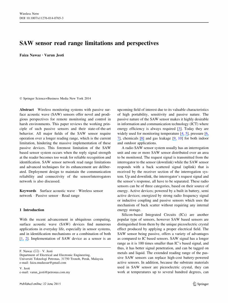
For designing SAW sensor two basic principles are
used. The delay line sensor and the resonator based sensors
as shown in Fig. 1. The resonators are narrowband device,
characterized by a resonance frequency dependent on a
physical quantity under investigation [11] whereas the
delay lines are wideband devices, characterized by a
propagation delay dependent on a physical quantity under
investigation [12]. Delay lines often require fast electronics
and large data storage memories with typical time con-
straints in the hundreds of MHz bandwidth, and 40-ns long
pulses. The reader interrogates either in time domain e.g.
by directly measuring the impulse response or in frequency
domain i.e. by measuring the transfer function [13].
Although SAW sensors have a longer read range as
compare to other passive sensors. There are still a need and
future perspectives to increase the readout distance.
Authors in [14] proposed the operation of a SAW device at
2.45 GHz ISM band and demonstrated a reading distance
of up to 11 m for indoor measurements and 13 m in out-
door operation. Time-position coding was used with one
reflector per 16 possible positions to visibly reduce the
losses and increase the read range.
The rest of this paper is organized such that the second
part of this paper deals with the operation principle and
design of SAW sensor devices, an overview of SAW sys-
tem, its components connectivity and signal processing is
also explained. In the third part the read range and com-
munication coverage of the SAW sensor network is eval-
uated and the capabilities of such systems are presented.
The last section gives the conclusion and future directions
in this research area.
2 Principles of operation
Transduction mechanism is the primary means of detection
employed by a SAW device. This method involves the
conversion of signals from the electrical domain to the
physical domain and vice versa [15]. The inter digital
transducer (IDT) enables the conversion of these signals
and therefore is the fundamental term of SAW technology.
2.1 SAW device operation principle
Piezoelectricity, the production of electrical charges by the
imposition of mechanical stress was discovered by Pierre
and Paul-Jacques Curie in 1880 while SAW was discov-
ered in 1885 by Lord Rayleigh [16]. All SAW devices use a
piezoelectric material, such as quartz crystal, to generate
the acoustic wave by applying a proper electrical field. A
mechanical wave is created which propagates through the
substrate and is then converted back to an electric field for
measurement. Since 1970, SAW devices have started
gaining attention for pulse compression radar, radios, and
bandpass filters for TV sets. A piezoelectric crystal is
electrically neutral and the design of devices is based on
combined Gaussian and Hooke’s law [17] governed by the
following equations.
Si ¼ SEijTj þ dki ð1Þ
Dl ¼ dlmTm þ eTlnEn ð2Þ
where i, j, m = 1, .6 and k, l, n = 1, 2, 3. S, D, E and T are
the strain, dielectric displacement, electric field and stress,
respectively. sEij , dki and eT
ln are the elastic compliances, the
piezoelectric constants and the dielectric permittivity.
SAW sensors are purely passive and the underlying
principle of the completely passive operation is the pie-
zoelectric effect. SAW sensor designing requires many
factors to be taken into consideration. The relative size,
sensitivity and efficiency is dependent on intended appli-
cation. For the wireless interrogation of SAW based sensor
a signal frequency of 40 MHz to a few GHz can be used.
The available bandwidth in the ISM bands increases with
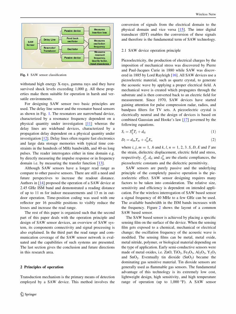
the frequency. Figure 2 shows the layout of a common
SAW based sensor.
The SAW based sensor is achieved by placing a specific
sensing film on the surface of the device. When the sensing
film gets exposed to a chemical, mechanical or electrical
change; the oscillation frequency of the acoustic wave is
modified. The sensing films can be metal, metal oxide,
metal nitride, polymer, or biological material depending on
the type of application. Early semi-conductive sensors were
made of metal oxides, i.e. ZnO, TiO2, Fe2O3, Al2O3, Y2O3
and SnO2. Eventually tin dioxide (SnO2) became the
dominating gas sensitive material. Tin dioxide sensors are
generally used as flammable gas sensors. The fundamental
advantage of this technology is its extremely low cost,
lightweight design, high sensitivity, and high temperature
range of operation (up to 1,000 �F). A SAW sensor
Fig. 1 SAW sensor classification
Wireless Netw
123
sensitive layer alters the SAW velocity resulting in fre-
quency shifts. For an ideal thin film this shift is calculated
as in (3).
Df ¼ k1 þ k2ð Þf 20 Vf q� k2f 2
0 tF4l � xþ lð ÞV2
r ðxþ 2lÞ ð3Þ
where k1; k2 are material constants, f0 is fundamental fre-
quency, Vf is film volume, q is film density, l is the elastic
modulus, and Vr is the raleigh velocity of the film.
2.2 SAW system operation principle
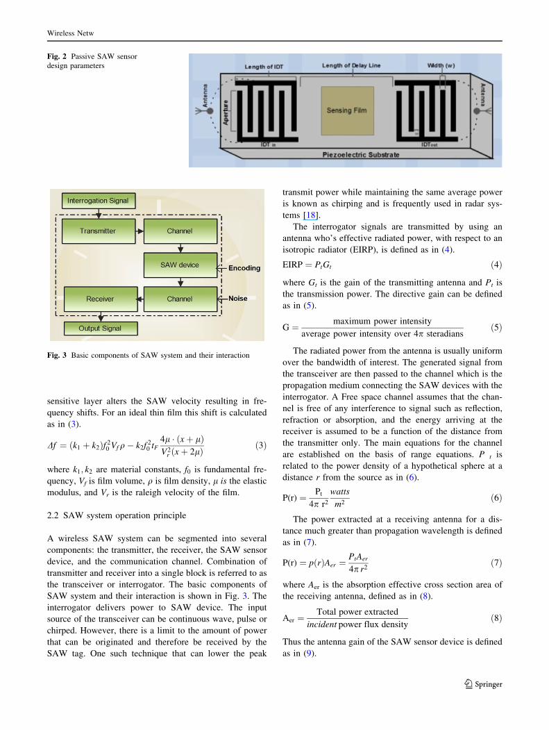
A wireless SAW system can be segmented into several
components: the transmitter, the receiver, the SAW sensor
device, and the communication channel. Combination of
transmitter and receiver into a single block is referred to as
the transceiver or interrogator. The basic components of
SAW system and their interaction is shown in Fig. 3. The
interrogator delivers power to SAW device. The input
source of the transceiver can be continuous wave, pulse or
chirped. However, there is a limit to the amount of power
that can be originated and therefore be received by the
SAW tag. One such technique that can lower the peak
transmit power while maintaining the same average power
is known as chirping and is frequently used in radar sys-
tems [18].
The interrogator signals are transmitted by using an
antenna who’s effective radiated power, with respect to an
isotropic radiator (EIRP), is defined as in (4).
EIRP ¼ PtGt ð4Þ
where Gt is the gain of the transmitting antenna and Pt is
the transmission power. The directive gain can be defined
as in (5).
G ¼ maximum power intensity
average power intensity over 4p steradiansð5Þ
The radiated power from the antenna is usually uniform
over the bandwidth of interest. The generated signal from
the transceiver are then passed to the channel which is the
propagation medium connecting the SAW devices with the
interrogator. A Free space channel assumes that the chan-
nel is free of any interference to signal such as reflection,
refraction or absorption, and the energy arriving at the
receiver is assumed to be a function of the distance from
the transmitter only. The main equations for the channel
are established on the basis of range equations. P t is
related to the power density of a hypothetical sphere at a
distance r from the source as in (6).
P(r) ¼ Pt
4p r2
watts
m2ð6Þ
The power extracted at a receiving antenna for a dis-
tance much greater than propagation wavelength is defined
as in (7).
P(r) ¼ pðrÞAer ¼PtAer
4p r2ð7Þ
where Aer is the absorption effective cross section area of
the receiving antenna, defined as in (8).
Aer ¼Total power extracted
incident power flux densityð8Þ
Thus the antenna gain of the SAW sensor device is defined
as in (9).
Fig. 2 Passive SAW sensor
design parameters
Fig. 3 Basic components of SAW system and their interaction
Wireless Netw
123
G ¼ 4p Ae
k2ðfor Aeiik2Þ ð9Þ
The power received at the sensor is then defined as in (10).
Pr ¼ EIRPGrk
2
ð4pr)2ð10Þ
The signal passing through the channel is often affected
by the path loss as defined in (11).
Ls ¼4 p r
k
� �2
ð11Þ
The path loss is dependent on the frequency of operation
which ultimately affect the antenna size, communication
range and complexity of device fabrication.
The remote sensor node without a transmitter, working
on the backscattered waveform principle is extremely
susceptible to the near-far problem. As there is no way to
perform power control on the sensors, spread spectrum
multiple-access gets affected by, the near-far problem in
DSSS/MA, as is discussed in [19]. In a network of SAW
sensors, wireless nodes are never located at exactly the
same distance from a reader, which results in a range of
different powers seen by the reader. For two-way line-of-
sight communication standard free-space link equation is
defined as in (12)
PR ¼PT GT GR
4pRcr=p
� �2ð12Þ
Here the path loss falls off by a factor of r2 However, in
case of a backscatter the link equation is given as in (13)
were received power falls off by a factor of r4 (with single
antenna to send and receive) [20].
PR ¼PT G2
TRGtk2X2M
4pRcrð Þ4�2B2F2
ð13Þ
where X is polarization mismatch, M is modulation factor,
� is an antenna gain penalty, B is path blockage and F2 is
fade margin. At this point, there is no method for con-
trolling the power reflected from the sensor. Thus, the near-
far problem affects the ability to perform direct sequence
spread spectrum.
In a wireless SAW network, voltage is induced in the
sensor antenna by the RF signal, and this induced voltage
should be rectified to direct current in order to be utilized.
The receiver antenna converts the RF power to DC as long
as 100 mV of voltage is induced. The relation between the
induced voltage and communication range is explained by
[21] as in (14).
Gk2
4p¼ Vtj j
8Wi
21
Rr þ RL
� �ð14Þ
where Vt is voltage induced, Wi is incident power density,
and Rr and RL are radiation and load resistances. k is the
wavelength of the signal.
The emitted power from the reader is another useful
parameter. There are constraints on the regulations for
effective isotropically radiated power (EIRP). According to
which a directional source antenna can have the 4 W
maximum EIRP (FCC rule on WLANs). Using Eqs. 12 and
14, the maximum distance to induce 100 mV on the node
for 4 W EIRP was calculated by [22]. At 2 GHz, 13 m
range was observed; this distance increased to 26 m at
1 GHz and 51 m at 500 MHz. However, the distance of
26 m at 1 GHz requires the 4 W EIRP source to be mobile
and must come close to the passive node to transmit the
power. These calculations also prove that multiple readers
in close proximity are needed for the practical coverage of
a wireless passive sensor network, deployed in a large
industrial environment.
3 SAW network range evaluation
3.1 Read range
SAW-based system can be modeled in numerous ways.
Fundamental and traditional techniques can be used to
predict the read range of SAW devices. Microcell envi-
ronment characterization has been used successfully for
SAW based broadcasting at varying distances [23–25],
however the SAW sensor range is currently limited to
centimeters or a few meters. Coherent integration of mul-
tiple responses was proposed in [26] to increase the range
of SAW sensor, however collision free simultaneous
interrogation of multiple SAW sensors over a wide area is
still a prevalent research topic.
Received signal strength (RSS) can be used to predict
the read range of passive devices [27]. The dual-slope
model derived from the two-ray model is a general
approach for predicting the RSS. Two-ray model is shown
in Fig. 4, where r1 is the direct ray and r2 is a multipath
ray and d is the distance. According to dual-slope model
the received signal power at the receiver can be expressed
using revised Friis formula as in (15)
Pr ¼ 10� log10
k4p
� �2
GtGrPtp1rN
1
1þ r=Ro
� �� �NL�2
0B@
1CA
ð15Þ
where Pr is the received power, Gr is the reader antenna
gain, Gt is the tag antenna gain, Pt is the transmitted power,
k is the wavelength, p is the polarization mismatch, N is the
variation of power before the breakpoint and NL is the
Wireless Netw
123
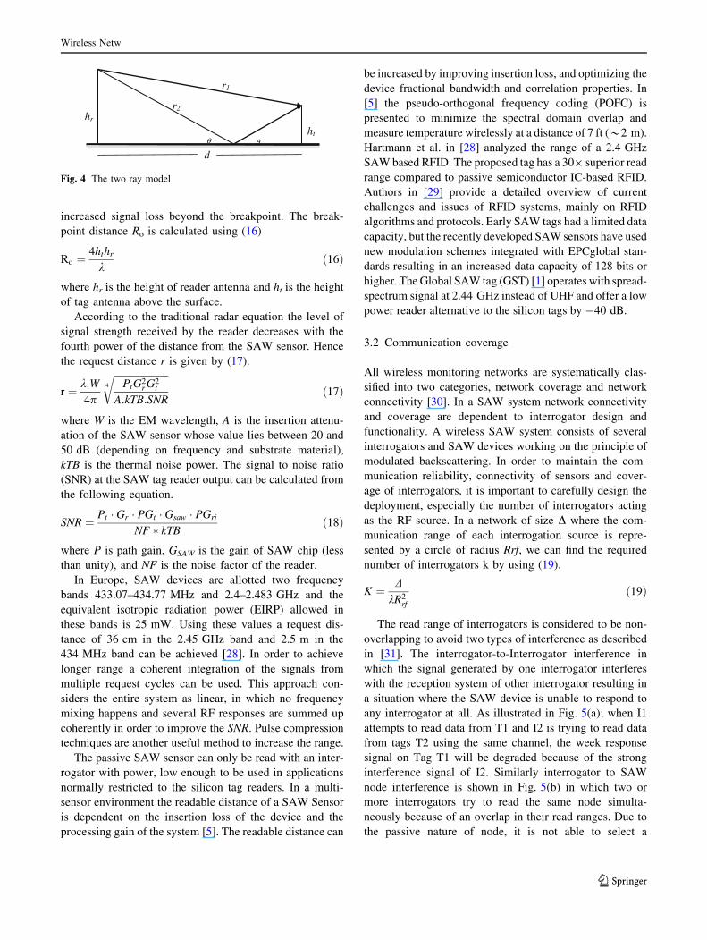
increased signal loss beyond the breakpoint. The break-
point distance Ro is calculated using (16)
Ro ¼4hthr
kð16Þ
where hr is the height of reader antenna and ht is the height
of tag antenna above the surface.
According to the traditional radar equation the level of
signal strength received by the reader decreases with the
fourth power of the distance from the SAW sensor. Hence
the request distance r is given by (17).
r ¼ k:W4p
ffiffiffiffiffiffiffiffiffiffiffiffiffiffiffiffiffiffiffiffiffiffiPtG2
r G2t
A:kTB:SNR
4
rð17Þ
where W is the EM wavelength, A is the insertion attenu-
ation of the SAW sensor whose value lies between 20 and
50 dB (depending on frequency and substrate material),
kTB is the thermal noise power. The signal to noise ratio
(SNR) at the SAW tag reader output can be calculated from
the following equation.
SNR ¼ Pt � Gr � PGt � Gsaw � PGri
NF � kTBð18Þ
where P is path gain, GSAW is the gain of SAW chip (less
than unity), and NF is the noise factor of the reader.
In Europe, SAW devices are allotted two frequency
bands 433.07–434.77 MHz and 2.4–2.483 GHz and the
equivalent isotropic radiation power (EIRP) allowed in
these bands is 25 mW. Using these values a request dis-
tance of 36 cm in the 2.45 GHz band and 2.5 m in the
434 MHz band can be achieved [28]. In order to achieve
longer range a coherent integration of the signals from
multiple request cycles can be used. This approach con-
siders the entire system as linear, in which no frequency
mixing happens and several RF responses are summed up
coherently in order to improve the SNR. Pulse compression
techniques are another useful method to increase the range.
The passive SAW sensor can only be read with an inter-
rogator with power, low enough to be used in applications
normally restricted to the silicon tag readers. In a multi-
sensor environment the readable distance of a SAW Sensor
is dependent on the insertion loss of the device and the
processing gain of the system [5]. The readable distance can
be increased by improving insertion loss, and optimizing the
device fractional bandwidth and correlation properties. In
[5] the pseudo-orthogonal frequency coding (POFC) is
presented to minimize the spectral domain overlap and
measure temperature wirelessly at a distance of 7 ft (*2 m).
Hartmann et al. in [28] analyzed the range of a 2.4 GHz
SAW based RFID. The proposed tag has a 309 superior read
range compared to passive semiconductor IC-based RFID.
Authors in [29] provide a detailed overview of current
challenges and issues of RFID systems, mainly on RFID
algorithms and protocols. Early SAW tags had a limited data
capacity, but the recently developed SAW sensors have used
new modulation schemes integrated with EPCglobal stan-
dards resulting in an increased data capacity of 128 bits or
higher. The Global SAW tag (GST) [1] operates with spread-
spectrum signal at 2.44 GHz instead of UHF and offer a low
power reader alternative to the silicon tags by -40 dB.
3.2 Communication coverage
All wireless monitoring networks are systematically clas-
sified into two categories, network coverage and network
connectivity [30]. In a SAW system network connectivity
and coverage are dependent to interrogator design and
functionality. A wireless SAW system consists of several
interrogators and SAW devices working on the principle of
modulated backscattering. In order to maintain the com-
munication reliability, connectivity of sensors and cover-
age of interrogators, it is important to carefully design the
deployment, especially the number of interrogators acting
as the RF source. In a network of size D where the com-
munication range of each interrogation source is repre-
sented by a circle of radius Rrf, we can find the required
number of interrogators k by using (19).
K ¼ DkR2
rf
ð19Þ
The read range of interrogators is considered to be non-
overlapping to avoid two types of interference as described
in [31]. The interrogator-to-Interrogator interference in
which the signal generated by one interrogator interferes
with the reception system of other interrogator resulting in
a situation where the SAW device is unable to respond to
any interrogator at all. As illustrated in Fig. 5(a); when I1
attempts to read data from T1 and I2 is trying to read data
from tags T2 using the same channel, the week response
signal on Tag T1 will be degraded because of the strong
interference signal of I2. Similarly interrogator to SAW
node interference is shown in Fig. 5(b) in which two or
more interrogators try to read the same node simulta-
neously because of an overlap in their read ranges. Due to
the passive nature of node, it is not able to select a
hr
ht
r1
r2
θ θ
d
Fig. 4 The two ray model
Wireless Netw
123
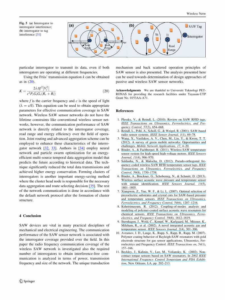
particular interrogator to transmit its data, even if both
interrogators are operating at different frequencies.
Using the Friis’ transmission equation k can be obtained
as in (20).
K ¼2kDf 2 V2
t
c2PtGtGrðRr þ RlÞ
ð20Þ
where f is the carrier frequency and c is the speed of light
(k = c/f). This equation can be used to obtain appropriate
parameters for effective communication coverage in SAW
network. Wireless SAW sensor networks do not have the
lifetime constraints like conventional wireless sensor net-
works, however, the communication performance of SAW
network is directly related to the interrogator coverage,
read range and energy efficiency over the field of opera-
tion. Joint routing and advanced aggregation scheme can be
employed to enhance these characteristics of the interro-
gator network [32, 33]. Authors in [34] employ neural
network and particle swarm optimization for an energy-
efficient multi-source temporal data aggregation model that
predicts the future according to historical data. The tech-
nique significantly reduced the total data transmissions and
achieved higher energy conservation. Forming clusters of
interrogators is another important energy-saving method
where the cluster head node is responsible for the necessary
data aggregation and route selecting decision [35]. The rest
of the network communication is done in accordance with
the default network protocol after the formation of cluster
structure.
4 Conclusion
SAW devices are vital in many practical disciplines of
mechanical and electrical engineering. The communication
performance of the SAW sensor network is associated with
the interrogator coverage provided over the field. In this
paper the radio frequency communication coverage of the
wireless SAW network is investigated also the required
number of interrogators to obtain interference-free com-
munication is analyzed in terms of power, transmission
frequency and size of the network. The unique transduction
mechanism and back scattered operation principles of
SAW sensor is also presented. The analysis presented here
can be used towards determination of design approaches of
passive and wireless SAW sensor networks.
Acknowledgments We are thankful to Universiti Teknologi PET-
RONAS for providing the research facilities under Yayasan-UTP
Grant No. 0153AA-A71.
References
1. Plessky, V., & Reindl, L. (2010). Review on SAW RFID tags.
IEEE Transactions on Ultrasonics, Ferroelectrics, and Fre-
quency Control, 57(3), 654–668.
2. Reindl, L., Pohl, A., Scholl, G., & Weigel, R. (2001). SAW-based
radio sensor systems. IEEE Sensor Journal, 1(1), 69–78.
3. Wang, X., Vasilakos, A. V., Chen, M., Liu, Y., & Kwon, T. T.
(2012). A survey of green mobile networks: Opportunities and
challenges. Mobile Network Applications, 17, 4–20.
4. Binder, A., & Fachberger, R. (2011). Wireless SAW temperature
sensor system for high-speed high-voltage motors. IEEE Sensors
Journal, 11(4), 966–970.
5. Saldanha, N., & Malocha, D. (2012). Pseudo-orthogonal fre-
quency coded wireless SAW RFID temperature sensor tags. IEEE
Transactions on Ultrasonics, Ferroelectrics, and Frequency
Control, 59(8), 1750–1758.
6. Binder, A., Bruckner, G., Schobernig, N., & Schmitt, D. (2013).
Wireless surface acoustic wave pressure and temperature sensor
with unique identification. IEEE Sensors Journal, 13(5),
1801–1805.
7. Xiangwen, Z., Yue, W. F., & Li, L. (2007). Optimal selection of
piezoelectric substrates and crystal cuts for SAW-based pressure
and temperature sensors. IEEE Transactions on Ultrasonics,
Ferroelectrics, and Frequency Control, 54(6), 1207–1216.
8. Kshetrimayum, R. (2012). Coupling-of-modes analysis and
modeling of polymer-coated surface acoustic wave resonators for
chemical sensors. IEEE Transactions on Ultrasonics, Ferro-
electrics, and Frequency Control, 59(8), 1812–1819.
9. Sternhagen, J., Wold, C., Kempf, W., Karlgaard, M., Mitzner, K.,
Mileham, R., et al. (2002). A novel integrated acoustic gas and
temperature sensor. IEEE Sensors Journal, 2(4), 301–306.
10. Avramov, I. D., Lange, K., Rupp, S., Rapp, B., Rapp, M. (2007).
Polymer coating behavior of Rayleigh-SAW resonators with gold
electrode structure for gas sensor applications, Ultrasonics, Fer-
roelectrics and Frequency Control. IEEE Transactions on, 54(1),
157–166.
11. Beckley, J., Kalinin, V., Lee, M., Voliansky, K. (2002). Non-
contact torque sensors based on SAW resonators. In 2002 IEEE
International Frequency Control Symposium and PDA Exhibi-
tion, New Orleans, LA, pp. 202–213.
Fig. 5 (a) Interrogator to
interrogator interference;
(b) interrogator to tag
interference [31]
Wireless Netw
123
12. Bulst, W., Fischerauer, G., & Reindl, A. L. (2001). State of the art
in wireless sensing with surface acoustic waves. IEEE Transac-
tions on Industrial Electronics, 48(2), 265–271.
13. Stelzer, A., Schuster, S., & Scheiblhofer, S. (2004). Readout unit
for wireless SAW sensors and ID-tags. In Proceedings of 2nd
international symposium acoustics wave development for future
mobile communication systems, Chiba.
14. Plessky, V., Ostertag,T., Kalinin, V., & Lyulin, B. (2010). SAW-
tag system with an increased reading range. In 2010 IEEE
International ultrasonics symposium proceedings.
15. Hartmann, C. S. (2002). Global SAW ID tag with large data
capacity. In Ultrasonics symposium.
16. Hribsek, M. F., Tosic, D. V., & Radosavljevic, M. R. (2010).
Surface acoustic wave sensors in mechanical engineering. FME
Transactions, 38, 11–18.
17. Dunn, S., & Whatmore, R. (2001). Transformation dependence of
lead zirconate titanate (PZT) as shown by PiezoAFM surface
mapping of sol–gel produced PZT on various substrates’. Inte-
grated Ferroelectrics, 38(1), 39–47.
18. Skolnik, M. I. (2003). Introduction to radar systems (3rd ed.).
Tata McGraw Hill.
19. Mohammed, A. F. (1993). Near-far problem in direct-sequence
code division multiple access systems. In 7th IEE European
conference on mobile and personal communications. 13–15 Dec
1993.
20. Griffin, J. D., & Durgin, G. D. (2009). Complete link budgets for
backscatter-radio and RFID systems. IEEE Antennas and Prop-
agation Magazine, 52(2), 11–25.
21. Balanis, C. A. (2009). Antenna theory: Analysis and design. (3rd
ed.). Wiley.
22. Akan, O. B., Isik, M. T., & Baykal, B. (2009). Wireless passive
sensor networks. IEEE Communications Magazine, 47(8), 92–99.
23. Bridgelall, R. (2002). Characterization of protocol-compatible
bluetooth/802.11 RFID tags. RFDesign, pp. 34–46.
24. Sarkar, T. K., Ji, Z., Kim, K., Medouri, A., Salazar-Palma, M.
(2003). A survey of various propagation models for mobile
communication. IEEE Antennas and PropagationMagazine,
45(3), 51–82.
25. Perera, S., Williamson, A., & Rowe, G. (1999). Prediction of
breakpoint distance in microcellular environments. Electronic
Letters, 35(14), 1135–1136.
26. Malocha, D., Pavlina, J., Gallagher, D., Kozlovski, N., Fisher, B.,
Saldanha, N., et al. (2008). Orthogonal frequency coded SAW
sensors and RFID design principles. In 2008 IEEE International
frequency control symposium.
27. Arumugam, D. D., Engels, D. W., & Modi, A. (2007). Environ-
mental and performance analysis of SAW-based RFID systems.
International Journal of Radio Frequency Identification Tech-
nology and Applications, 1(2), 204–235.
28. Hartmann, C., & Claiborne, L. (2007). Fundamental limitations
on reading range of passive IC-based RFID and SAW-based
RFID. In IEEE international conference on RFID, 26–28 March
2007.
29. Xie, L., Yin, Y., Vasilakos, A., & Lu, S. (2014). Managing RFID
data: Challenges, opportunities and solutions. Communications
Surveys & Tutorials, IEEE, PP(99), 1–18.
30. Li, M., Li, Z., & Vasilakos, A. V. (2013). A Survey on topology
control in wireless sensor networks: Taxonomy, comparative
study and open issues. Proceedings of the IEEE, 101(12),
2538–2557.
31. Nawaz, F., jeoti, V., Awang, A., & Driberg, M. (2013). Reader to
reader anticollision protocols in dense and passive RFID envi-
ronment. In 11 IEEE Malaysian international conference on
communication, Kuala lumpur, Malaysia.
32. Wei, G., Ling, Y., Guo, B., Xiao, B., & Vasilakos, A. V. (2011).
Prediction-based data aggregation in wireless sensor networks:
Combining grey model and Kalman Filter. Computer Commu-
nications, 34(2011), 793–802.
33. Xiang, L., Luo, J., & Vasilakos, A. (2011). Compressed data
aggregation for energy efficient wireless sensor networks. In 8th
annual IEEE communication society conference on sensor, Mesh
and Ad hoc communications and networks.
34. Guo, W., Xiong, N., Vasilakos, A. V., Chen, G., & Cheng, H.
(2010). Multi-source temporal data aggregation in wireless sensor
networks. Wireless Personal Communication, 56(2011),
359–370.
35. Liu, Y., Xiong, N., Zhao, Y., Vasilakos, A., Gao, J., & Jia, Y.
(2010). Multi-layer clustering routing algorithm for wireless
vehicular sensor networks. IET Communications, Special Issue on
Vehicular Ad Hoc and Sensor Networks, 4(7), 810–816.
Faiza Nawaz received her M.S.
degrees from GIK Institute of
Engineering and Technology,
Pakistan in 2010, She is cur-
rently a Ph.D. student in Elec-
trical and Electronics
Engineering Department at
Universiti Teknologi PETRO-
NAS, Malaysia. Her research
interests are in the area of
wireless networking with
emphasis on wireless SAW
based sensor networks.
Varun Jeoti received his Ph.D.
degree from Indian Institute of
Technology Delhi India in 1992.
He worked on several sponsored
R&D projects in IIT Delhi and
IIT Madras during 1980–1989.
He was a Visiting Faculty in
Electronics Department in
Madras Institute of Technology,
Anna University for about
1 year from 1989 to 1990 and
joined Delhi Institute of Tech-
nology for next 5 years till
1995. He moved to Electrical
and Electronic Engineering
School of Universiti Sains Malaysia in 1995 and joined Electrical and
Electronic Engineering Department of Universiti Teknologi PET-
RONAS in 2001. His research interests are in the area of signal
processing, surface acoustic wave (SAW) devices, wireless SAW
sensor network and wireless communication for maritime applications
besides others.
Wireless Netw
123
Related Documents


