HAL Id: hal-01022211 https://hal-enac.archives-ouvertes.fr/hal-01022211 Submitted on 9 Sep 2014 HAL is a multi-disciplinary open access archive for the deposit and dissemination of sci- entific research documents, whether they are pub- lished or not. The documents may come from teaching and research institutions in France or abroad, or from public or private research centers. L’archive ouverte pluridisciplinaire HAL, est destinée au dépôt et à la diffusion de documents scientifiques de niveau recherche, publiés ou non, émanant des établissements d’enseignement et de recherche français ou étrangers, des laboratoires publics ou privés. Satellite link emulation platform for aeronautical application validation Fabien Garcia, Alain Pirovano, Mathieu Magnaudet To cite this version: Fabien Garcia, Alain Pirovano, Mathieu Magnaudet. Satellite link emulation platform for aeronautical application validation. ICSSC 2010, AIAA 28th International Communications Satellite Systems Conference, Aug 2010, Anaheim, United States. pp xxx, 10.2514/6.2010-8794. hal-01022211

Welcome message from author
This document is posted to help you gain knowledge. Please leave a comment to let me know what you think about it! Share it to your friends and learn new things together.
Transcript

HAL Id: hal-01022211https://hal-enac.archives-ouvertes.fr/hal-01022211
Submitted on 9 Sep 2014
HAL is a multi-disciplinary open accessarchive for the deposit and dissemination of sci-entific research documents, whether they are pub-lished or not. The documents may come fromteaching and research institutions in France orabroad, or from public or private research centers.
L’archive ouverte pluridisciplinaire HAL, estdestinée au dépôt et à la diffusion de documentsscientifiques de niveau recherche, publiés ou non,émanant des établissements d’enseignement et derecherche français ou étrangers, des laboratoirespublics ou privés.
Satellite link emulation platform for aeronauticalapplication validation
Fabien Garcia, Alain Pirovano, Mathieu Magnaudet
To cite this version:Fabien Garcia, Alain Pirovano, Mathieu Magnaudet. Satellite link emulation platform for aeronauticalapplication validation. ICSSC 2010, AIAA 28th International Communications Satellite SystemsConference, Aug 2010, Anaheim, United States. pp xxx, �10.2514/6.2010-8794�. �hal-01022211�
Satellite Link Emulation Platform for Aeronautical
Application Validation
F. Garcia∗ , A. Pirovano† , M. Magnaudet‡
ENAC : Ecole Nationale de l’Aviation Civile, Toulouse, France
In this paper we present our approach toward the validation of new aeronautical ap-
plications in satellite communication environment through the use of link emulation and
exogenous traffic generation. We describe the hardware and software components of the
satellite emulation platform we have implemented for a project named CAPITOLE that has
been initiated through the Aerospace Valley world competitiveness cluster. After a short
presentation of the overall project, a list of hardware and software components used is
given and detailed. Lastly, we explain how the platform itself is validated through network
metrology techniques.
I. Introduction
As the air traffic is forecasted to grow, the European Union has launched the SESAR (Single EuropeanSky ATM Research) program. The aim of this program is to encourage innovation in Air Traffic Control
through the introduction of state-of-the-art technologies. In this context, the European Space Agency (ESA)is defining a new satellite standard named IRIS dedicated to digital air-ground communications for Air TrafficManagement often known as datalink. By 2020 IRIS should contribute to the modernization of air trafficmanagement by providing digital datalinks in continental and oceanic airspace.
In order to take full advantage of this new satellite-based communication solution, several projects havebeen initiated through the Aerospace Valley world competitiveness cluster. One of these projects, in which weare involved, is the CAPITOLE project co-funded by the Aerospace Valley pole (www.aerospace-valley.com)and the French government (Direction générale de la compétitivité, de l’industrie et des services). Thisproject aims at defining new aeronautical services based on satellite communications, such as real-timeweather reports for aircraft pilots. CAPITOLE is mainly concerned with ATC (Air Traffic Control) andAOC (Airline Operational Communication) services, covering aircontroller/pilot communications and airlinecommunications respectively.
In this context, the ENAC/Leopart laboratory has been involved in defining, proposing and implementinga means to estimate and study the behaviour of the new communicating applications that will be developedin the CAPITOLE project in a satellite environment.
There are several ways to validate application performances for a given type of network link, among themsimulation, emulation and tests on real-systems.
• Simulation relies on models for both the application and the network and runs in simulated time (asopposed to real-time), its strengths are the re-usability of the tests and the ease of automation, butthe results will only be as accurate as the models and will only reflect the aspects which have actuallybeen coded in the models. Simulation is often used for protocol development and testing.
• Emulation relies on deploying real applications on a network that reproduce the characteristics of thereal network, allowing deployment of real applications (as opposed to models of applications) withend-users. Again the results will only be as accurate as the representativity of the network emulation,though qualitative results can be produced through the intervention of real users.
∗Associate professor, ENAC/Leopart, [email protected].†Associate professor, Head of Leopart, [email protected].‡Research assistant, ENAC/Leopart, [email protected].
1 of 11
American Institute of Aeronautics and Astronautics
• Real-system tests are the most accurate that can be thought of, but in the case of satellite systems,they imply prohibitive costs that prevent their use in the definition phase of new services.
On the one hand because there is a need to test real applications, considering CAPITOLE projectrequirements, and on the other hand, because the IRIS project is still in the definition phase, the emulationapproach has been chosen. The aim of the satellite emulation platform developed by the ENAC/Leopartlaboratory is to estimate and measure the behaviour of new applications that will be developed in theCAPITOLE project. It has to be noted that this platform emulates the satellite link at packet level.
II. System and service characterization
The emulation of the system is based on the characterization of the link between the ground and theaircraft. As we decided to develop an exogenous traffic generator, there is also a need to characterize networktraffic flows in these communications.
II.A. ESA’s telecommunication program IRIS
The main objective of the ESA (European Space Agency)/IRIS program is to propose a new air-groundcommunication system for ATM (Air Traffic Management). By 2020, this system should be the satellite-based solution for the Single European Sky ATM Research (SESAR) program. IRIS will contribute to themodernization of air traffic management by providing digital datalinks to cockpit crews in continental andoceanic airspace. The ESA/IRIS program is composed of three phases:
1. The first is the definition phase. The main objective is to provide inputs on satellite capabilities inorder to make important choices for the subsequent phases.
2. The second aims to develop and validate the new satellite-based communication system dedicated tothe future European ATM system.
3. The third and final phase will mainly focus on verification and certification of the pre-operationalsystem. According to the ESA, it will also provide technical support to the deployment of the satellite-based communication system.
The IRIS Program completed its definition phase (Phase 1) in january 2009 and is now in the first partof phase two1. Considering the actual IRIS program outcomes, some key points still remaining undefined,accurately characterizing the satellite link which will be proposed as the future system is difficult and eveninfeasible.
For the moment, according to Ref. 1 several solutions have been considered during Phase 1 activitiessuch as the use of specific techniques for a new dedicated standard, the adaptation of the AMSS standardor the adaptation of DVB-S2/RCS. Nevertheless, some elements may allow to list, estimate, or bound theparameters which have to be considered to characterize the future IRIS satellite link above the link level.
The first is that the solution is based on geostationary satellites. Considering line-of-sight communication,the one-way delay introduced by the system will be at least 250 milliseconds. As the satellite link shouldbe shared by several aircraft, adequate access control has to be defined in order to prevent or avoid packetcollision. This access control technique could introduce jitter on the delay, considering existing satellitesystems and specific equipment constraints. The capacity should be between 10 kbit/s and 10 Mbit/s. Forinstance current Inmarsat AeroH satellite aeronautical systems offer a bit rate of around 10 kbit/s.
Finally, as the bit error rate is generally known, a close approximation of the PER (packet error rate)can be deduced. The bit error rate is the ratio of received bits corrupted by noise or interference divided bythe total number of transferred bits. As several corrupted bits may be found in a single packet, PER will beless than or equal to BER. Generally, we can consider that bit error rates on satellite links are at least inthe order of 10−12 on more recent systems and at worst in the order of 10−5 in AMSS (Aeronautical MobileSatellite Service), proposed by Inmarsat, for instance. For a data packet length of N bits the expected PERPp can be expressed relative to the bit error probability Pe as :
Pp = 1− (1− Pe)N (1)
2 of 11
American Institute of Aeronautics and Astronautics

In our case, we made the assumption that all packets containing at least one corrupted bit will bediscarded at link level. Hence, from now on we will consider the PER as the loss ratio parameter of the link.
It has to be noted that one-way delay, jitter, bit rate, and PER parameters may have different values orstatistical properties considering the forward or return channel of the satellite communication system.
II.B. Datalink Traffic characterization
The EUROCONTROL/FAA document "Communications Operating Concept and Requirements for theFuture Radio System" (COCR)2 defines the Future Radio System (FRS) sub-system that encompasses thePhysical and Data Link Layers of the satellite system. Our satellite link emulator aims at reproducing thecharacteristics of the network as seen by packets arriving at the interface between the FRS and Networklayer in terms of delay, loss and throughput. The delay and loss parameters can be set at fixed values or bedefined in terms of a probability function that they should obey. The throughput on the other hand can beset as a pair of values, the maximum data rate and the Maximum Transmission Unit in the FRS. The reasonwe do not stick with fixed delay and loss on a satellite link (where jitter is mostly negligible and losses aremainly due to interferences) is the traffic generated by other aircraft and applications sharing the same link.To further improve the way this traffic is taken into account, we include an exogenous traffic generator inour platform. This generator allows the user to emulate the competition for resources on the satellite linkwith realistic traffic. To allow for easy and accurate definition of this traffic, both packet and applicationflow level generation will be supported. That is to say the user can define exogenous traffic as stochasticlaws on inter departure time and size of packets or simply specify the type and number of application flowshe wishes to emulate.
To do so, the first task consists in determining properties of the network traffic that will be emulated.Studies underlining interesting information related to aeronautical datalink traffic properties and specificitieshave been conducted.
As explained in Ref. 2, datalink traffic may have different properties considering flight phase and servicesprovided. Ref. 3 describes five phases : airport, departure, cruise, arrival, airport. Moreover, three classes,with different properties and requirements, are generally considered in the aeronautical datalink context :
• ATC (Air Traffic Control), mostly dedicated to controllers and pilots.
• AOC/AAC (Airline Operational Communications/Airline Administrative Communications), mainlyfor airline companies
• APC ( Airline Passenger Communications), for passengers applications.
In order to estimate the necessary capacity of a satellite communication system dedicated to aeronauticaldatalink, Ref. 3 gives the communication pattern of one aircraft conforming with COCR. Some propertiesof the expected traffic are given :
• the expected message size is from 77 to 21077 bytes long
• the peak rate for one aircraft , considering some short messages with stringent latency requirements,should be around 15 Kbps
• the average throughput per aircraft should be a few bps
Based on these conclusions and the aircraft traffic density given in Ref. 4, an estimation of the informationthroughput for all aircraft flying simultaneously over a given area during the busiest day of the year ispossible.
III. Satellite link emulation
Our satellite emulation platform consists of two software components : the link emulator which emulatesthe link characteristics (delay, throughput and losses); and the traffic generator which allows for tests on aloaded network. These two components run on linux servers with dedicated networks. The following sectionspresent first the hardware part of the platform, and then the two software components.
3 of 11
American Institute of Aeronautics and Astronautics
III.A. Hardware components
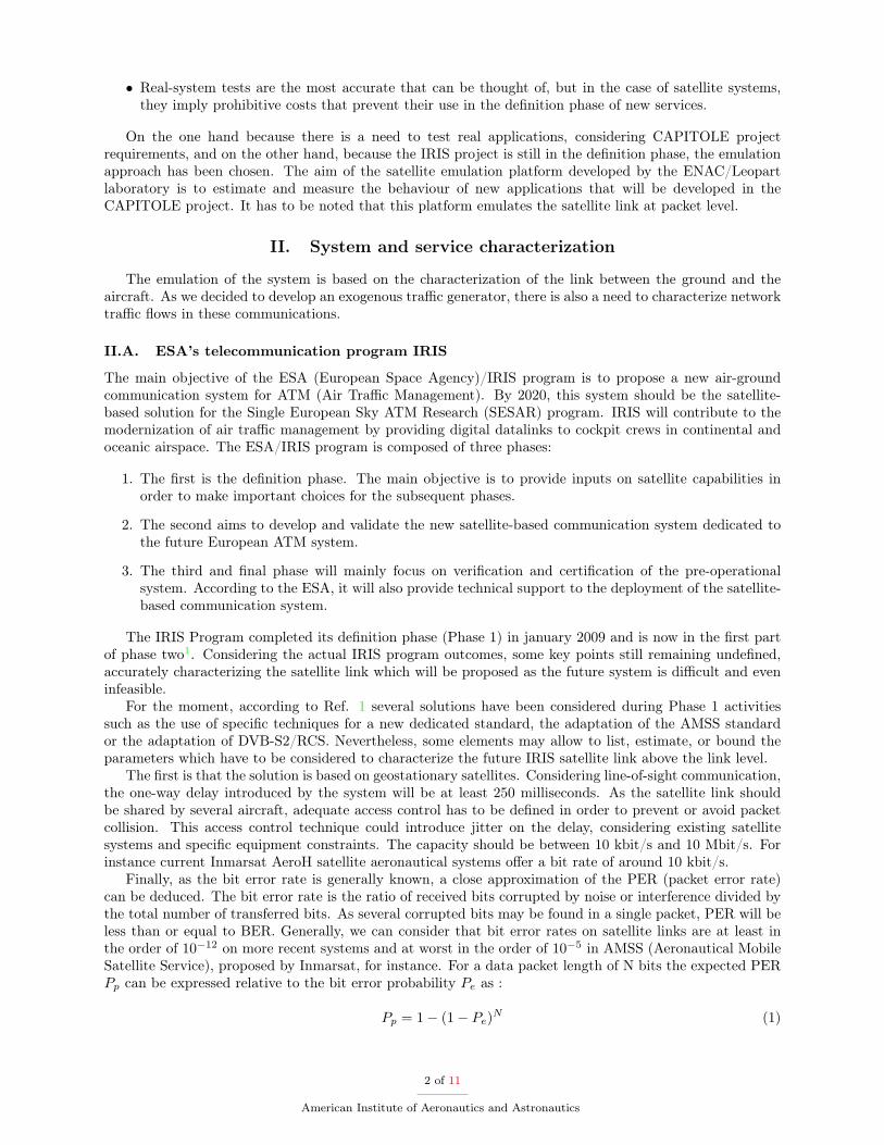
Our satellite emulation platform consists of three Linux servers and two 1000 Base TX Ethernet switches.One Linux computer hosts the link emulation application, the other two host the traffic generator. Theover-provisioning of the switch allows us to enforce the fact that competition for resources should onlyhappen on the satellite link. This platform uses IPv6 as its network protocol, which is consistent with ICAOrecommendations for ATN/IP systems5. The use of these standards allows a user to simply plug an Ethernetcable into a station in order to test an application.
Figure 1. Emulation platform overview
III.B. Software component
III.B.1. Satellite link emulation
The philosophy of the software conception has been to give priority to the user experience and to makethe emulator usable for an average user, unaware of the subtleties of the Linux kernel parameters for trafficcontrol. So the GUI of the software allows the user to specify networks features and to keep ignoring theinternal Linux machinery.
As shown in figure 2, three parameters can be specified :
1. Delay: propagation delay in millisecond. It has associated jitter and probability law, as well as acorrelation percentage.
2. Loss: percentage and correlation percentage.
3. Throughput: in bits per second.
To emulate a new link, the user has to associate a set of parameters to two of the available networkinterfaces, one for each traffic flow direction. The parameters can be different for each selected interface.Once selected, an emulated link can be launched, stopped, restarted and deleted.
4 of 11
American Institute of Aeronautics and Astronautics

Figure 2. Link emulator GUI
In order to gain independence from any external tool, we chose not to build the network emulator ontop of the command line tool tc which is the standard tool for Linux traffic control . We chose instead todirectly address kernel modules via the C open source library libnl. Besides libnl, the various components ofthe software were written in JAVA and interfaced with the C component by using the Java Native Interfaceframework. Thus, the data coming from the user are stored in two XML files via a persistence layer whichis based on the Java Architecture for XML Binding (JAXB). The graphical user interface is based on theSWT/JFACE libraries, chosen for performance and aesthetic reasons. Attention has been paid to makea clean separation between the various components such that it should be possible to substitute anotherimplementation to one of them without changing the others. The final link emulation architecture is shownin figure 3.
The two modules shown in the kernel space in figure 3, netem and tbf, each emulate some parameters ofthe link. Netem6 is used to emulate delays and losses, whereas tbf7 is used to emulate the delay of the link.The Token Bucket Filter (TBF) is in charge of slowing down packets so they respect a given maximum rate.In the terminology introduced in Ref. 8, TBF is a traffic shaper. Other scheduling methods beside TBFcould have been used but several sources7,9 and the netem author himself point to TBF as the preferredbandwidth limitation tool. We will show later in the validation section that our platform would benefit froma new approach.
III.B.2. Exogenous traffic generator
The exogenous traffic generator is built around two pieces of software : a sink, to be launched on the receiverside, and the traffic generator, to be launched on the sender side. The sink is a simple graphical tool thatallows the user to open a list of ports, it also provides some information about the incoming packets such astheir number and the inter-arrival time.
On the sender side, the traffic generator allows the user to define and control a list of UDP flows. In thecurrent version, a UDP flow is characterized by :
1. a destination address and port number,
5 of 11
American Institute of Aeronautics and Astronautics

Figure 3. Software Architecture of the link emulator
2. a statistical law governing the packet size (constant, uniform, normal or exponential),
3. a statistical law governing the inter-arrival time (constant, uniform, normal or exponential).
The last two parameters allow us to easily implement the communications as described in the COCRdocument2.
In the next version of the generator, each UDP flow will be attached to a source type (e.g. : aircraft withAOC and ATC services) and we will provide, as a new functionality, a source duplication tool. This way wewill be able to, for example, emulate the traffic generated by a fleet of aircraft each having the same trafficprofile.
IV. Platform Validation and First results
In this section, we first present results concerning the validation of our emulation platform, and thensome user feedback on perceived application quality in the context of satellite link communication.
IV.A. Platform validation
As we said in previous sections, our link emulation software allows us to emulate throughput, losses anddelays. In order to validate our platform, we will therefore test each parameter in turn and measure itsvalues in several configurations. It should be noted that these tests are not sufficient to fully validate ourplatform. They will, however, give us confidence in the behaviour of our emulation but cannot test allpossible values for each parameter. It will therefore be necessary to repeat these tests each time new linksare to be emulated.
In the following sections, we first present the validation tool we developed, and then the methodologyand the results of the validation for each parameter.
6 of 11
American Institute of Aeronautics and Astronautics
IV.A.1. Network measurement tool
In order to validate our platform, we have developed a measurement tool that is able to measure the one-waydelay; throughput; and loss ratio of a given network link between two hosts. This tool, launched at the twoends of the link, generates UDP packets at a given rate and in one direction. Each packet is marked with itssequence, its size and the time at which it was sent. At the reception side, the packets are just stored alongwith their reception time.
In order to compute the one-way delay, both hosts need to synchronize their clocks, we used the NetworkTime Protocol10 (NTP) for this task. Throughput calculations have been made both as an average and asan instantaneous value. The average value is based on the throughput of the measurement session. Theinstantaneous value is computed as the size of a packet divided by the inter-arrival time between the currentpacket and the next. Loss calculations were made on average using the sequence numbers of the packetsreceived.
This tool will soon be made available as open-source software under the name OWDMeter (One-WayDelay Meter).
IV.A.2. Throughput validation
To validate throughput emulation, we used OWDMeter, which uses timestamped UDP packets in order tomeasure delays, throughput and losses on a link. Using UDP packets sent at a rate higher than the oneconfigured in the emulation, we were able to measure the throughput at the receiver side. It is to be notedthat our tool outputs the rate at the application level whereas our emulation takes place at the networklevel, it is therefore necessary to take into account the overhead of IPv6 and UDPv6 protocols. IPv6 addsa 40 byte header and UDP adds an 8 byte header so for a 1000 byte packet at application level, we send a1048 byte IP datagram.
We tested two different rates :
• 10Mb/s which is typical of low speed Ethernet Local Area Networks;
• 64Kb/s which is the expected throughput available on one channel of the future IRIS satellite.
Our first batch of tests showed rather poor results for the emulation at 64 Kbits/s. This was traced toa problem with the Linux queuing system. We first sized the queue so as to reflect classical router queues11
of around 100 packets (for a total of 150000 byte queues). Such a queue, if full, would take 18.6 s to emptyat 64 Kbit/s, which is unreasonable. During these tests, we noticed that long queues tended to be discardedby Linux (all their packets being destroyed at once), generating bursts of losses. As this behaviour was notthe intended one, where once full the queue would reject only new packets arriving, we decided to limit thequeue size so as to have a maximum waiting time of 1sa in the queue.
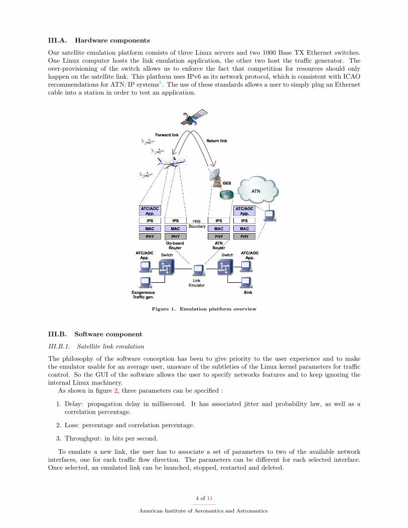
Table 1 sums up the configuration used for each scenario as well as the measured throughput at thereceiver side. Figure 4(a) shows the instantaneous measured throughput (at user level) during the length ofa test.
Configured emulation packet size Test duration Average Measured Average Measured
throughput (IP Level) (IP Level) Throughput (User Level) Throughput (IP Level)
10Mb/s 1048 bytes 600 s 9.256 Mb/s 9.7 Mb/s
64Kb/s 1048 bytes 600 s 59.147 Kb/s 61.986 Kb/s
Table 1. Throughput validation results
These results show that the throughput of the link was limited by TBF. The accuracy of the limitation,though high enough for our purpose, could be enhanced by modifying the shaping method. Actually it hasalready been noted in Ref. 9 that the sensitivity of TBF to small irregularities in input traffic leads to packetlosses above the expected ratio, which in turn causes a lower average throughput. Furthermore, as can beseen in figure 4(b), the token bucket technique allows small transient bursts to be sent at a high rate. Thesetwo problems lead us to conclude that a new throughput limitation method should be used. At the time ofwriting, such a technique is still to be implemented.
aThe value of 1s was found empirically not to cause problem, further research in the subject will have to be done.
7 of 11
American Institute of Aeronautics and Astronautics
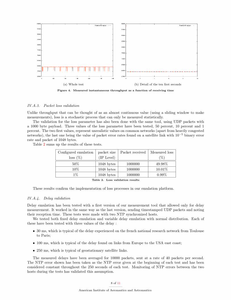
(a) Whole test (b) Detail of the ten first seconds
Figure 4. Measured instantaneous throughput as a function of receiving time
IV.A.3. Packet loss validation
Unlike throughput that can be thought of as an almost continuous value (using a sliding window to makemeasurements), loss is a stochastic process that can only be measured statistically.
The validation for the loss parameter has also been done with the same tool, using UDP packets witha 1000 byte payload. Three values of the loss parameter have been tested, 50 percent, 10 percent and 1percent. The two first values, represent unrealistic values on common networks (apart from heavily congestednetworks), the last one being the value of packet error rates found on a satellite link with 10−5 binary errorrate and packet of 1048 bytes.
Table 2 sums up the results of these tests.
Configured emulation packet size Packet received Measured loss
loss (%) (IP Level) (%)
50% 1048 bytes 1000000 49.98%
10% 1048 bytes 1000000 10.01%
1% 1048 bytes 1000000 0.99%
Table 2. Loss validation results
These results confirm the implementation of loss processes in our emulation platform.
IV.A.4. Delay validation
Delay emulation has been tested with a first version of our measurement tool that allowed only for delaymeasurement. It worked in the same way as the last version, sending timestamped UDP packets and notingtheir reception time. These tests were made with two NTP synchronized hosts.
We tested both fixed delay emulation and variable delay emulation with normal distribution. Each ofthese have been tested with three values of the delay :
• 30 ms, which is typical of the delay experienced on the french national research network from Toulouseto Paris;
• 100 ms, which is typical of the delay found on links from Europe to the USA east coast;
• 250 ms, which is typical of geostationary satellite links.
The measured delays have been averaged for 10000 packets, sent at a rate of 40 packets per second.The NTP error shown has been taken as the NTP error given at the beginning of each test and has beenconsidered constant throughout the 250 seconds of each test. Monitoring of NTP errors between the twohosts during the tests has validated this assumption.
8 of 11
American Institute of Aeronautics and Astronautics
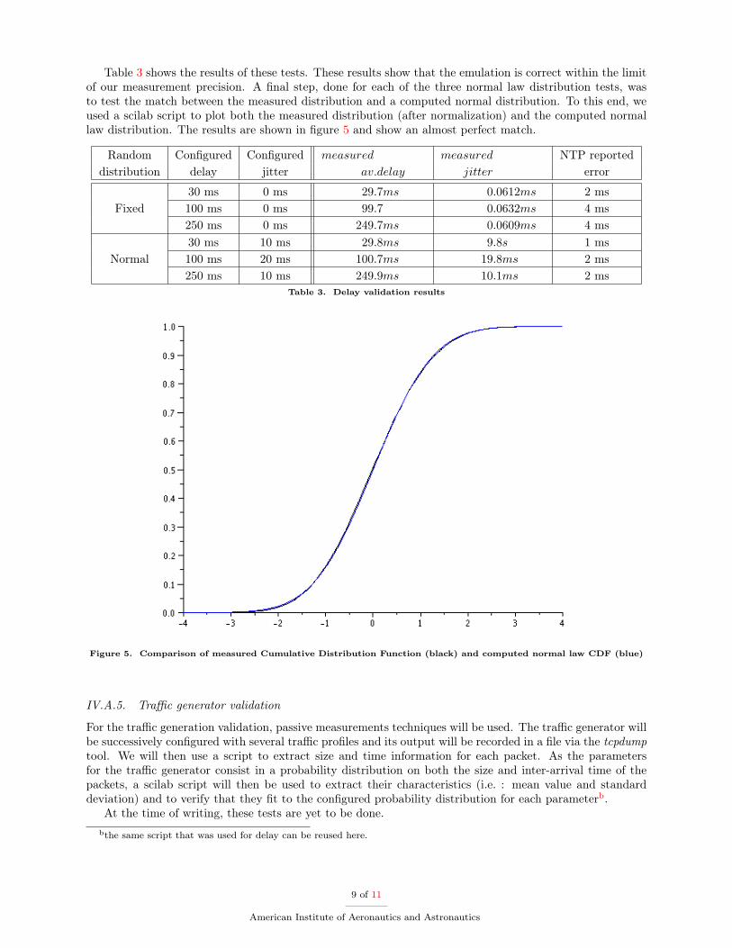
Table 3 shows the results of these tests. These results show that the emulation is correct within the limitof our measurement precision. A final step, done for each of the three normal law distribution tests, wasto test the match between the measured distribution and a computed normal distribution. To this end, weused a scilab script to plot both the measured distribution (after normalization) and the computed normallaw distribution. The results are shown in figure 5 and show an almost perfect match.
Random Configured Configured measured measured NTP reported
distribution delay jitter av.delay jitter error
30 ms 0 ms 29.7ms 0.0612ms 2 ms
Fixed 100 ms 0 ms 99.7 0.0632ms 4 ms
250 ms 0 ms 249.7ms 0.0609ms 4 ms
30 ms 10 ms 29.8ms 9.8s 1 ms
Normal 100 ms 20 ms 100.7ms 19.8ms 2 ms
250 ms 10 ms 249.9ms 10.1ms 2 ms
Table 3. Delay validation results
Figure 5. Comparison of measured Cumulative Distribution Function (black) and computed normal law CDF (blue)
IV.A.5. Traffic generator validation
For the traffic generation validation, passive measurements techniques will be used. The traffic generator willbe successively configured with several traffic profiles and its output will be recorded in a file via the tcpdump
tool. We will then use a script to extract size and time information for each packet. As the parametersfor the traffic generator consist in a probability distribution on both the size and inter-arrival time of thepackets, a scilab script will then be used to extract their characteristics (i.e. : mean value and standarddeviation) and to verify that they fit to the configured probability distribution for each parameterb.
At the time of writing, these tests are yet to be done.
bthe same script that was used for delay can be reused here.
9 of 11
American Institute of Aeronautics and Astronautics

IV.B. User experience evaluation
After the validation of the link emulation part of our platform, we wished to test some common applicationsin order to evaluate the satellite channel from the application users perspective. We used four applicationsin these tests, a web application, an ftp application, an interactive remote login application (ssh) and a videostreaming application (using vlc and a live webcam capture). These applications have been chosen so as tohave both TCP and UDP protocols, and both interactive and streaming (one-way) applications.
The link we emulated was a satellite link with 64 Kbps throughput, 250 ms one-way delay and 10−2 lossratio. For each application, the users have noted the perceived quality of the application.
Web browsing Web browsing performance on a satellite link depends heavily on the site being browsed.Web pages containing mainly text load in an acceptable time, whereas pages with more images will take alonger time. So far, the conclusion are unsurprising as the reduced bandwidth lengthen the download timeof each image. The delay induced by the satellite is not really noticeable for the user.
SSH remote login Secure Shell (ssh) allows a user to remotely and, above all, securely connect to anhost. We tested both command line interaction and display redirectionc with different results. Although thedelay induced by the satellite link is noticeable in command line, due to the display showing half a secondlater than the typing of the commands, working through this remote connexion is possible. In remote displaymode though, the delay and the low throughput do not allow a easy interaction on a GUI.
FTP transfer We tried FTP both to evaluate the interaction level and the download speed of a file.Although the interaction was at the same level as with ssh in command line, the download speed was,unsurprisingly, really low. It took almost an hour to download a 15 MB file. For this application, no TCPenhancing technique (such as described in Ref. 12,13) can improve the download time, as the limiting factorresides in the 64 Kbps throughput rather than in the TCP mechanismsd.
Video streaming We used a webcam to send live video (using a UDP stream) to a vlc server on the otherside of the emulated satellite link. The video was successively configured to send 64 Kbps, 128 Kbps and512 Kbps toward the server. In each cases, the results were similar, the video shown was of low to averagequality. The delay induced by the satellite is irrelevant in this case as it acts only as an time offset, not alimiting factor.
These tests, although their results are not new to the network community, emphasize our view of applicationvalidation through emulation : we now have a good understanding of the usability of each of these applicationsin a satellite communication environment. By letting users test new applications in a realistic environment,we can validate their use in several conditions without resorting to expensive, real-systems tests.
V. Conclusion
This paper presents our approach of aeronautical application validation in a satellite communicationenvironment. This approach uses both link parameters emulation as well as traffic generation to reproducethe characteristics of a loaded satellite link, allowing us to test applications in a most realistic way. Oursystem being built as a generic platform for network emulation, it allows us to represent various satellitelinks by entering the right parameters in our GUI. Validation tests have been run on our platform using bothactive and passive measurements of the various parameters to extract relevant values with error margins.These have shown the platform reliability in terms of emulation of the satellite link. For example, the testson delay emulation show no error above the precision advertised by the NTP synchronisation process. Lastly,the use of a simple GUI allows users with only basic network knowledge to emulate different links in an easyway.
Future works on this platform will consist of two phases : the first part, already in progress, consistsin the enhancement of the exogenous traffic generator as described in section III.B.2 (and its subsequentvalidation); the second part will be to write a linux kernel module to shape packets so as to replace theTBF shaper. On the one hand, the addition of source types, and the possibility to replicate them will allow
cThis consists in displaying a remote application on the local computerdThe (bandwidth ∗ round trip time) product for this link is below the standard 64KB for a TCP receive window.
10 of 11
American Institute of Aeronautics and Astronautics
users to easily define the load of the emulated link as a function of the number of aircraft and their currentstate. On the other hand, the replacement of the TBF shaper will increase the accuracy of the throughputemulation.
Acknowledgments
The authors wish to thank Jean-Baptiste Laborde, Loïc Jurdy and Rémi Blondin, students at ENACand Jane Jean Kiam, trainee at the Leopart laboratory, for their help in the validation tests. We also wishto thank Nadine Atwood and Graeme Riddick for their review and comments on this paper.
References
1ESA, “IRIS Project, http://telecom.esa.int/iris,” .2EURCONTROL/FAA, “Communications Operating Concept and Requirements for the Future Radio System, COCR
version 2,” 2007.3Ricard, N., “ESA Iris Programme Overview,” http://www.ffg.at/getdownload.php?id=3581, April 2009.4EUROCONTROL, “Eurocontrol Long Term Forecast,” http://www.eurocontrol.int/statfor/public/standard_page/
forecast3_reports.html.5ICAO, “Doc 9896, Manual on the Aeronautical Telecommunication Network (ATN) using Internet Protocol Suite (IPS)
Standards and Protocols.” 2010.6Hemminger, S., “Network Emulation with NetEm,” Linux Conf Au, April 2005.7Hubert, B., Graf, T., Maxwell, G., van Mook, R., van Oosterhout, M., Schroeder, P. B., Spaans, J., and Larroy, P.,
“Linux advanced traffic control HOWTO rev1.43,” 10 2003.8Blake, S., Black, D., Carlson, M., Davies, E., Wang, Z., and Weiss, W., “RFC 2475: An Architecture for Differenctiated
Services,” December 1998.9Stattenberger, G., Braun, T., Scheidegger, M., Brunner, M., and Stüttgen, H. J., “Performance evaluation of a Linux
DiffServ implementation,” Computer Communications, Vol. 25, No. 13, 2002, pp. 1195 – 1213.10Mills, D., “Network Time Protocol (Version 3) Specification, Implementation,” 1992.11Appenzeller, G., Keslassy, I., and McKeown, N., “Sizing Router Buffers,” In proceedings of ACM SIGCOMM , 2004, pp.
281–292.12Jacobson, V., Braden, R., and Borman, D., “TCP Extensions for High Performance,” 1992.13Border, J., Kojo, M., Griner, J., Montenegro, G., and Shelby, Z., “Performance Enhancing Proxies Intended to Mitigate
Link-Related Degradations,” RFC 3135 (Informational), June 2001.
11 of 11
American Institute of Aeronautics and Astronautics
Related Documents


![Apple ][ Emulation on an AVR Microcontroller Emulation ... · Apple ][ Emulation on an AVR Microcontroller Emulation eines Apple ][ auf einem AVR Mikrocontroller Maximilian Strauch](https://static.cupdf.com/doc/110x72/5d494b4588c99334058bd1f6/apple-emulation-on-an-avr-microcontroller-emulation-apple-emulation.jpg)
