Venus Atmospheric Explorer Efrain Ortiz | Christopher Bill | Julius Chua 05/05/2016

Welcome message from author
This document is posted to help you gain knowledge. Please leave a comment to let me know what you think about it! Share it to your friends and learn new things together.
Transcript

Venus Atmospheric ExplorerEfrain Ortiz | Christopher Bill | Julius Chua
05/05/2016
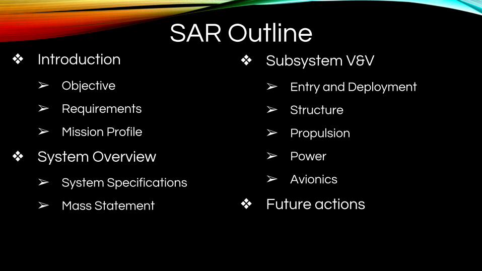
SAR Outline❖ Introduction
➢ Objective
➢ Requirements
➢ Mission Profile
❖ System Overview
➢ System Specifications
➢ Mass Statement
❖ Subsystem V&V
➢ Entry and Deployment
➢ Structure
➢ Propulsion
➢ Power
➢ Avionics
❖ Future actions
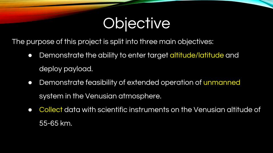
ObjectiveThe purpose of this project is split into three main objectives:
● Demonstrate the ability to enter target altitude/latitude and
deploy payload.
● Demonstrate feasibility of extended operation of unmanned
system in the Venusian atmosphere.
● Collect data with scientific instruments on the Venusian altitude of
55-65 km.

Customer Requirements
● Entry capsule deploys blimp at target optimal location
● 6 month continuous flight duration
● Cruise altitude of 55-65 km for the mission duration
● Must be solar-powered
● System should carry a 20 kg scientific payload
● Communicate data back to Earth

(1)Entry at 200 km altitude
Ve= 11 km/s
Time of descent- 25 sec
(2)Drogue parachute deploy
Mach 1.5125 km
Front cover release
Terminal Velocity-170 m/s
Duration 17 seconds
(3)Payload separation from aft cover.
105 km
Gondola falling at terminal velocity
(4)Main Parachute Deploys
Mach .8 100 km
Average Descent rate of 82 m/s
Duration 13 min
(5)Partial inflation under main parachuteTime of inflation: 10 minTank Jettison
Operational conditions:Cruise Altitude: 57 kmCruise Latitude: 75°Wind Speed: 40 m/s
(5)
Mission Profile

System Overview➢ System Characteristics
○ Deploys blimp at optimal
destination
○ Cruise altitude: 55 km
○ Cruise latitude: 75o
○ Thrust: 9.17 kN
○ Flexible Solar array efficiency: 12%
○ EoL Power loss: 10% or 8144 Watts
○ EoL Volume Lost: 0.4%
○ Carries 20 kg science payload
Length: 27 m
Diameter:8.2 m
[4] Jenkins, C. H. "Inflatable Solar Arrays." Gossamer Spacecraft: Membrane and Inflatable Structures Technology for Space Applications. Vol. 191. Reston, VA: American Institute of Aeronautics and Astronautics, 2001. 464-68. Print.
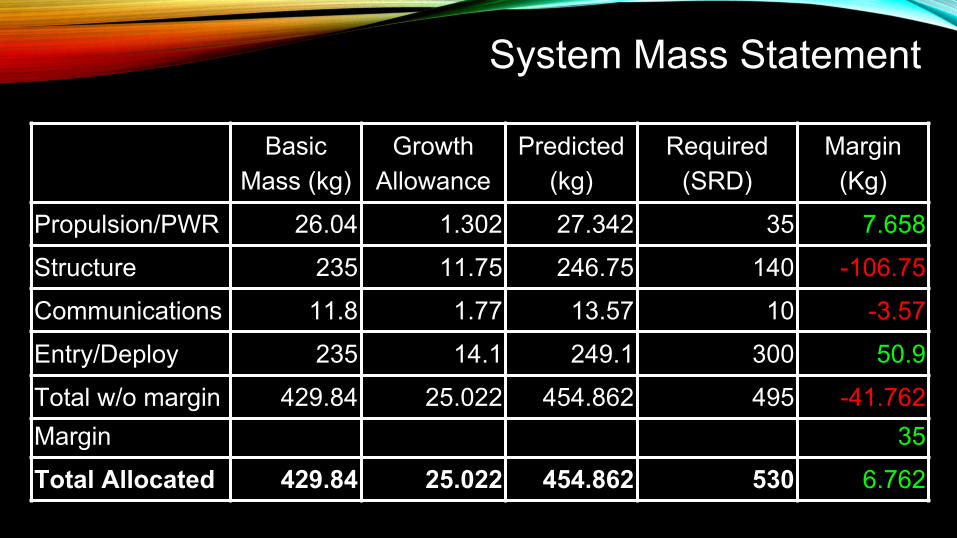
Basic Mass (kg)
Growth Allowance
Predicted (kg)
Required (SRD)
Margin (Kg)
Propulsion/PWR 26.04 1.302 27.342 35 7.658
Structure 235 11.75 246.75 140 -106.75
Communications 11.8 1.77 13.57 10 -3.57
Entry/Deploy 235 14.1 249.1 300 50.9
Total w/o margin 429.84 25.022 454.862 495 -41.762Margin 35
Total Allocated 429.84 25.022 454.862 530 6.762
System Mass Statement
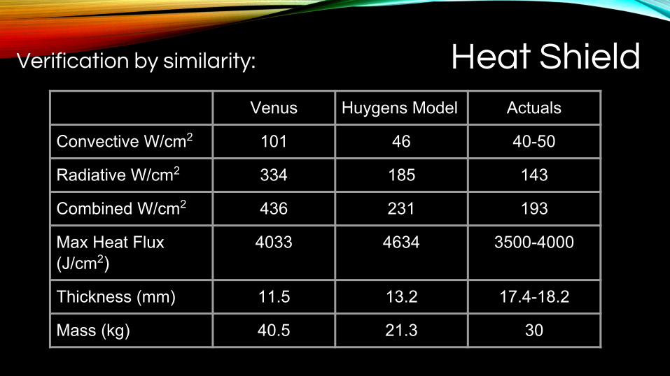
Heat Shield Verification by similarity:
Venus Huygens Model Actuals
Convective W/cm2 101 46 40-50
Radiative W/cm2 334 185 143
Combined W/cm2 436 231 193
Max Heat Flux (J/cm2)
4033 4634 3500-4000
Thickness (mm) 11.5 13.2 17.4-18.2
Mass (kg) 40.5 21.3 30
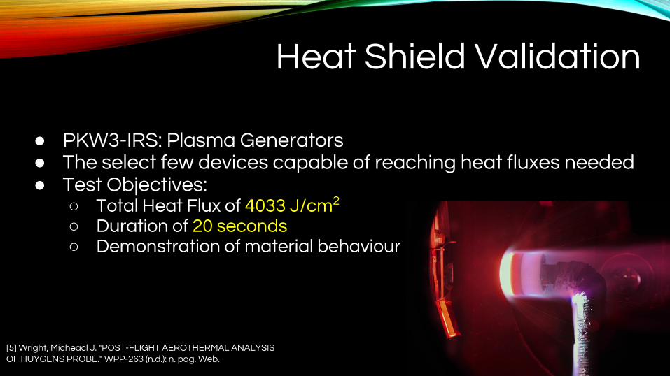
Heat Shield Validation
● PKW3-IRS: Plasma Generators ● The select few devices capable of reaching heat fluxes needed● Test Objectives:
○ Total Heat Flux of 4033 J/cm2 ○ Duration of 20 seconds○ Demonstration of material behaviour
[5] Wright, Micheacl J. "POST-FLIGHT AEROTHERMAL ANALYSIS OF HUYGENS PROBE." WPP-263 (n.d.): n. pag. Web.
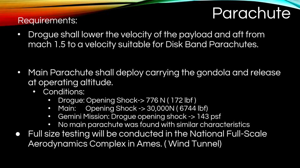
ParachuteRequirements:
• Drogue shall lower the velocity of the payload and aft from mach 1.5 to a velocity suitable for Disk Band Parachutes.
• Main Parachute shall deploy carrying the gondola and release at operating altitude. • Conditions:
• Drogue: Opening Shock-> 776 N ( 172 lbf )• Main: Opening Shock -> 30,000N ( 6744 lbf)• Gemini Mission: Drogue opening shock -> 143 psf• No main parachute was found with similar characteristics
● Full size testing will be conducted in the National Full-Scale Aerodynamics Complex in Ames. ( Wind Tunnel)

Tank Verification
Burst Testing Result
Pressure (x2) 14e7 pa
Max Stress 2.033e9
Yield Str 1.57e9
Min FOS 0.75
Failed Before 2.0 FOS
Tank Test Result Material Carbon fiber-T1000
MEOPMaximum ExpectedOperating Pressure
Yield Str Max stress
Min FOS
7e7 pa 1.57e9 pa 1.02e9 pa 1.75

Leak Rate Summary
Mission Duration 6 Months
Material Mylar & Kapton
Volume Leak Rate 2.52E-04 m3/hr
BoL Lift 2,352 N
Lift Lost 8.86 N or 2 lbs
% in Volume Lost 0.4%
Leak Rate Verification
[1] "958. Permeation and Outgassing of Vacuum Materials." Vacuum 23.12 (1973): 472. Outgassing and Permeating. Professional Engineering Computations (PEC, Inc), 31 Mar. 2003. Web. Oct.-Nov. 2015.[2] Hogat, J. T. "Investigation of the Feasibility of Developing Low Permeability Polymeric Films." /tardir/mig/a304557.tiff (n.d.): n. pag. The Boeing Company, NASA, Dec. 1971. Web. Oct.-Nov. 2015.

Envelope Verification
• Requirements:• ΔPressure of 7290 N/m2
• Minimum FOS: 1.5• Load bearing material: Dyneema fibers
• Challenges• Meshing
• Assumptions (hoop Stress)• Simulation
• thickness/pressure [ (x1,000), (x10,000) ]
[3] Nicolai, Leland M., and Grant E. Carichner. Fundamentals of Aircraft and Airship Design. Reston, VA: American Inst. of Aeronautics and Astronautics, 2013. Print.
(xC)
(xC)


1,000x 10,000x
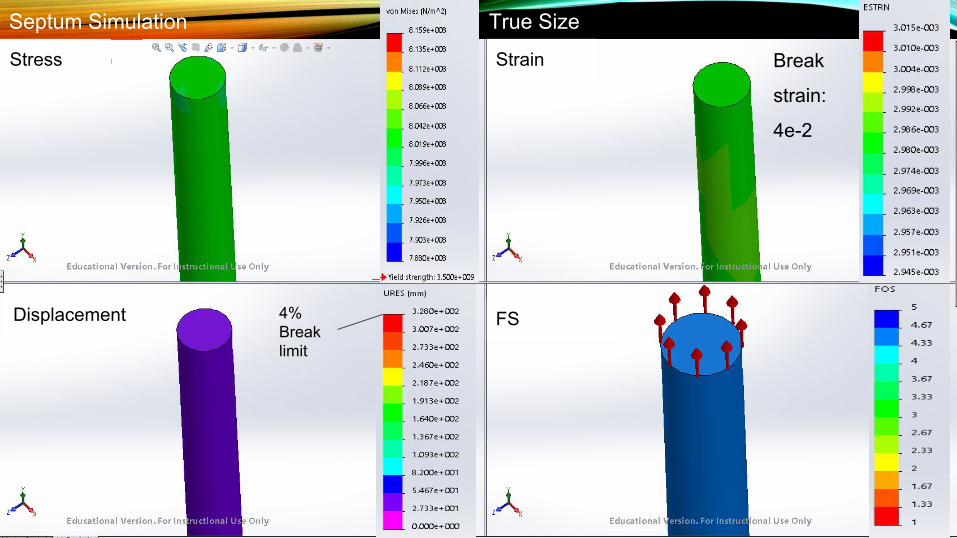
SeptumStress Strain
Displacement FS4%Break limit
Break
strain:
4e-2
True SizeSeptum Simulation

PropulsionRequirements
Cruise Speed: 40 m/s
Power Required: 40311 Watts
Thrust Required: 9.17 kN
Test:-Wind tunnel with V
in= 40 m/s
-Air density = 1.225 kg/m
-Propeller RPM = 2700 Target Velocity: 43.31 m/s
CharacteristicsPropeller Efficiency: 80%
Propeller Diameter: 12.55 m
Number of blades: three
Motor power density: 5.92 kW/kg
Motor weight: 6.81 kg

Power
Requirements
EoL Power Required: 40.55 kW
Lifespan Required: 6 months
CharacteristicsMass/Area of solar array: 0.178 kg/m2
Area of solar array: 241.29 m2
Total mass of solar array: 42.95 kg
Power generated: 76.9 kW
Solar cell degradation: 3 %/year
EoL power generated: 68.8 kW
TestingLife cycle test (6 months) in cyclic corrosion chamber at -13°C in sulfuric
acid environment
Testing power output with simulated solar input of 2.61 kW/m2 at 1 month intervals
Maximum power generation loss of 30% after 6 months Image credit: Astroinstruments
Image credit: Vanguard Space Technologies
Future Actions Parachute
● Result: Opening Shock Force exceeded cluster loads of parachutes on market. ○ Action: Decrease the diameter of the main parachute ○ Consequence: Faster decent, meaning shorter time of inflation
○ Alternate Action: Delay drogue deployment ○ Consequence: Drogue will expect higher loads

Future Actions (Enveloped & Tank)Envelope
• Investigate Envelope FOS discrepancy• Simulated: 1.92• Predicted: 3.1
• Need Weight reduction• 28 kg overweight
Action
• True scale simulation• Use other verification methods
Repercussions
• Subsystem Design may change
Helium Tank
• Failed Burst Test• Need thicker tank shell
Action
• Thicken shell wall• Thicken heat shield
Repercussions
• Will be heavier on entry• Less inflation time• Faster orbit entry• Changes on heat shield

References[1] "958. Permeation and Outgassing of Vacuum Materials." Vacuum 23.12 (1973): 472. Outgassing and Permeating.
Professional Engineering Computations (PEC, Inc), 31 Mar. 2003. Web. Oct.-Nov. 2015. <http://lpc1.clpccd.cc.ca.us/lpc/tswain/lect8.pdf>.
[2] Hogat, J. T. "Investigation of the Feasibility of Developing Low Permeability Polymeric Films." /tardir/mig/a304557.tiff (n.d.): n. pag. The Boeing Company, NASA, Dec. 1971. Web. Oct.-Nov. 2015. <http://www.dtic.mil/dtic/tr/fulltext/u2/a304557.pdf>.
[3] Nicolai, Leland M., and Grant E. Carichner. Fundamentals of Aircraft and Airship Design. Reston, VA: American Inst. of Aeronautics and Astronautics, 2013. Print.
[4] Jenkins, C. H. "Inflatable Solar Arrays." Gossamer Spacecraft: Membrane and Inflatable Structures Technology for Space Applications. Vol. 191. Reston, VA: American Institute of Aeronautics and Astronautics, 2001. 464-68. Print.
[5] Wright, Michael J. "POST-FLIGHT AEROTHERMAL ANALYSIS OF HUYGENS PROBE." WPP-263 (n.d.): n. pag. Web.
Related Documents


