Multimedia Projector SERVICE MANUAL PRODUCT CODE PLC-XU78 PLC-XU75 1 122 390 00 (KH3AC) 1 122 416 00 (KZ3AC) 1 122 391 00 (LH3AC) 1 122 417 00 (LZ3AC) 1 122 391 02 (LH3CC) 1 122 417 02 (LZ3CC) Original Version REFERENCE NO. SM5110874-00 FILE NO. Model No. PLC-XU78 PLC-XU75 U.S.A, Canada, Europe, U.K, Asia Chassis No. KH3-XU7800 KZ3-XU7500 Match the Chassis No. on the unit's back cover with the Chassis No. in the Service Manual. If the Original Version Service Manual Chassis No. does not match the unit’s, additional Service Literature is re- quired. You must refer to “Notices” to the Original Service Manual prior to servicing the unit.

Welcome message from author
This document is posted to help you gain knowledge. Please leave a comment to let me know what you think about it! Share it to your friends and learn new things together.
Transcript
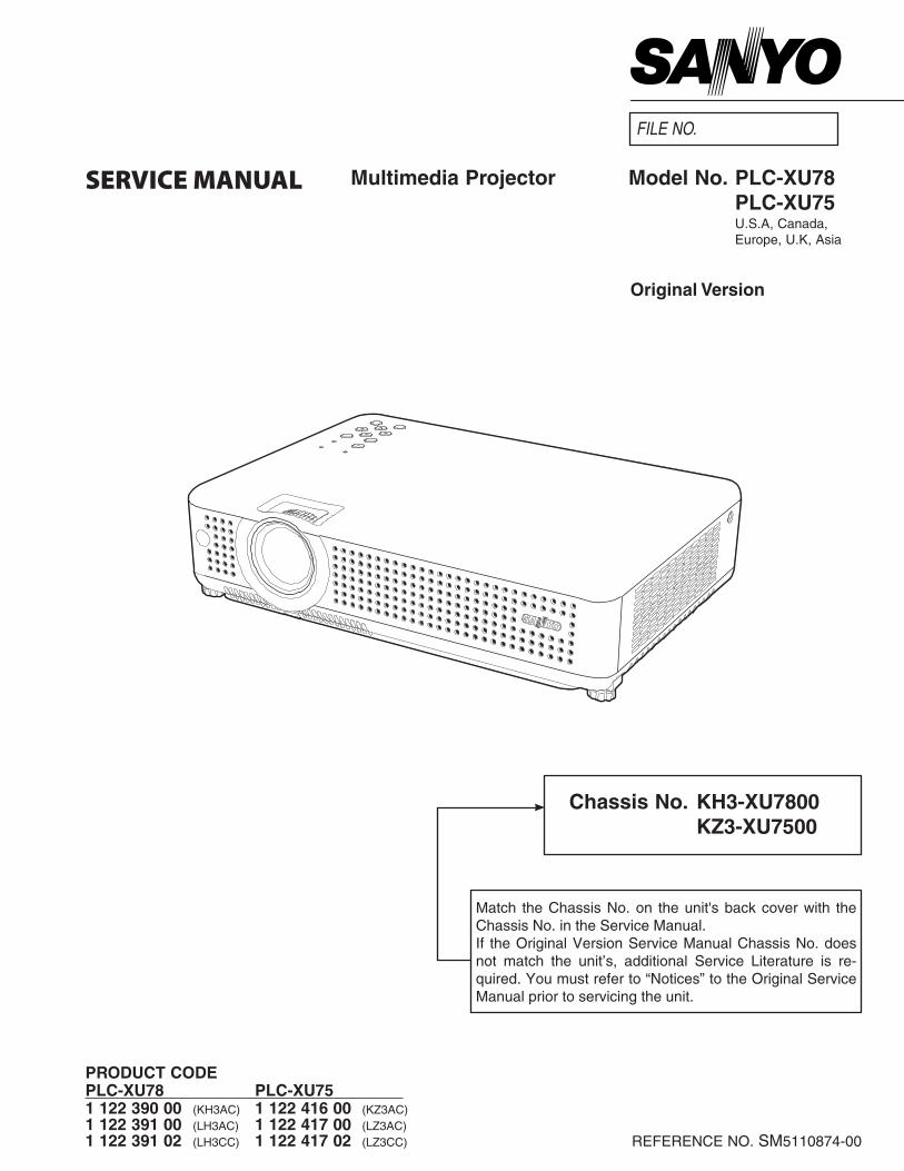
Multimedia ProjectorSERVICE MANUAL
Product code PLc-Xu78 PLc-Xu75 1 122 390 00 (KH3AC) 1 122 416 00 (KZ3AC)1 122 391 00 (LH3AC) 1 122 417 00 (LZ3AC)1 122 391 02 (LH3CC) 1 122 417 02 (LZ3CC)
original Version
REFERENCE NO. SM5110874-00
FILE NO.
Model No. PLc-Xu78 PLc-Xu75 U.S.A, Canada, Europe, U.K, Asia
chassis No. KH3-Xu7800 KZ3-Xu7500
Match the Chassis No. on the unit's back cover with the Chassis No. in the Service Manual. If the Original Version Service Manual Chassis No. does not match the unit’s, additional Service Literature is re-quired. You must refer to “Notices” to the Original Service Manual prior to servicing the unit.
-�-
ContentsSERVICE MANUAL ....................................................... 1Contents ........................................................................ �Safety Instructions ......................................................... 3
Safety Precautions ..................................................... 3Product Safety Notice ................................................. 3Service Personnel Warning ........................................ 3
Specifications ................................................................ 4Circuit Protections ......................................................... 5
Thermal switch ........................................................... 5Lamp cover switch ...................................................... 5Fuse ............................................................................ 5Warning temperature and power failure protection .... 6Air filter care and cleaning .......................................... 6
Security Function Notice ................................................ 7Lamp Replacement ....................................................... 8
Lamp replacement ...................................................... 8How to reset Lamp Replace Counter ......................... 8How to check Lamp Used Time .................................. 8
Mechanical Disassembly ............................................... 9Optical Parts Disassembly ........................................... 15Adjustments ................................................................. �1
Adjustments after Parts Replacement ...................... �1Optical Adjustments ..................................................... ��
Contrast adjustment ................................................. ��Integrator lens adjustment ........................................ �3Relay lens-Out adjustment ....................................... �4
Electrical Adjustments ................................................. �5Service Adjustment Menu Operation ........................ �5Memory IC (IC1371) Replacement ........................... �5Circuit Adjustments ................................................... �6Test Points and Locations ........................................ 30Service Adjustment Data Table ................................ 31
Chassis Block Diagrams .............................................. 49Chassis over view ..................................................... 49System control .......................................................... 50Power supply & protection circuit ............................. 51Fan control circuit ..................................................... 5�
Troubleshooting ........................................................... 53Indicators and Projector Condition ........................... 53No Power .................................................................. 54No Picture ................................................................. 55No Sound .................................................................. 56System Control & I/O Port Functions (IC301) ........... 57
Waveform .................................................................... 58Cleaning ...................................................................... 59
IC Block Diagrams ....................................................... 60Electrical Parts List ...................................................... 64
Electrical Parts Location ........................................... 65Electrical Parts List ................................................... 66
Mechanical Parts List .................................................. 84Cabinet Parts Location ............................................. 84Optical Parts Location .............................................. 85Mechanical Parts List ............................................... 89
Diagrams & Drawings ..................................................A1Parts description and reading in schematic diagram ...A�Schematic Diagrams ...................................................A3Printed Wiring Board Diagrams ...................................A9Pin description of diode, transistor and IC .................A13Note on Soldering ......................................................A14
-3-
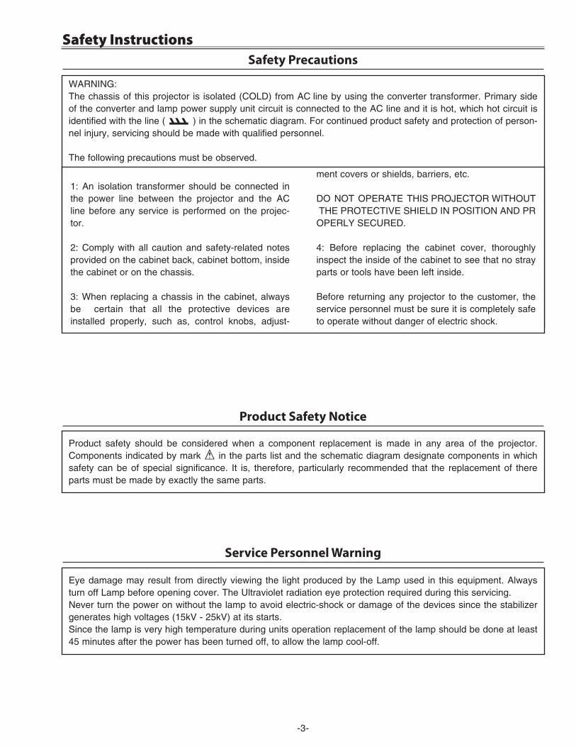
Safety Instructions
WARNING:The chassis of this projector is isolated (COLD) from AC line by using the converter transformer. Primary side of the converter and lamp power supply unit circuit is connected to the AC line and it is hot, which hot circuit is identified with the line ( ) in the schematic diagram. For continued product safety and protection of person-nel injury, servicing should be made with qualified personnel.
The following precautions must be observed.
Safety Precautions
1: An isolation transformer should be connected in the power line between the projector and the AC line before any service is performed on the projec-tor.
�: Comply with all caution and safety-related notes provided on the cabinet back, cabinet bottom, inside the cabinet or on the chassis.
3: When replacing a chassis in the cabinet, always be certain that all the protective devices are installed properly, such as, control knobs, adjust-
ment covers or shields, barriers, etc.
DO NOT OPERATE THIS PROJECTOR WITHOUT THE PROTECTIVE SHIELD IN POSITION AND PROPERLY SECURED.
4: Before replacing the cabinet cover, thoroughly inspect the inside of the cabinet to see that no stray parts or tools have been left inside.
Before returning any projector to the customer, the service personnel must be sure it is completely safe to operate without danger of electric shock.
Service Personnel Warning
Eye damage may result from directly viewing the light produced by the Lamp used in this equipment. Always turn off Lamp before opening cover. The Ultraviolet radiation eye protection required during this servicing.Never turn the power on without the lamp to avoid electric-shock or damage of the devices since the stabilizer generates high voltages (15kV - �5kV) at its starts.Since the lamp is very high temperature during units operation replacement of the lamp should be done at least 45 minutes after the power has been turned off, to allow the lamp cool-off.
Product Safety Notice
Product safety should be considered when a component replacement is made in any area of the projector. Components indicated by mark ! in the parts list and the schematic diagram designate components in which safety can be of special significance. It is, therefore, particularly recommended that the replacement of there parts must be made by exactly the same parts.
-4-
Specifications
This symbol on the nameplate means the product is Listed by Underwriters Laboratories Inc. It is designed and manufactured to meet rigid U.L. safety stan-dards against risk of fire, casualty and electrical hazards.
Mechanical Information ProjectorType Multi-mediaProjector Dimensions(WxHxD) 13.19"x3.14"x9.39"(335mmx79.7mmx238.4mm)(Notincludingadjustablefeet) NetWeight 6.83lbs(3.1kgs) FeetAdjustment 0˚to10.0˚
Panel resolution LCDPanelSystem 0.6"TFTActiveMatrixtype,3panels PanelResolution 1,024x768dots NumberofPixels 2,359,296(1,024x768x3panels)
Signal compatibility ColorSystem PAL,SECAM,NTSC,NTSC4.43,PAL-M,PAL-N HighDefinitionTVSignal 480i,480p,575i,575p,720p,1035i,and1080i ScanningFrequency H-sync.15~100kHz,V-sync.50~100Hz
optical Information ProjectionImageSize(Diagonal) Adjustablefrom40"to300" ProjectionLens F1.65~1.81lenswithf22.5~27mmwithmanualzoomandfocus ThrowDistance 4.6-41.3’(1.4m-12.6m) ProjectionLamp PLC-XU75:200W PLC-XU78:220W
Interface VideoInputJack RCATypex1 S-VidedoInputJack MiniDIN4pinx1 AudioInputJacks RCATypex2 ComputerInput1/ComponentInputTerminal AnlaogRGB(MiniD-sub15pin)Terminalx1 ComputerInput2/MonitorOutputTerminal AnlaogRGB(MiniD-sub15pin)Terminalx1(In/Outswitchable) Computer/ComponentAudioInputJack MiniJack(stereo)x1 ServicePortConnector MiniDIN8pinx1 AudioOutputJack MiniJack(stereo)x1(Variable)
Audio InternalAudioAmp 1.0WRMS Built-inSpeaker 1speaker,ø1.1"(28mm)Power VoltageandPowerConsumption AC100~120V(3.2AMax.Ampere),50/60Hz(TheU.S.AandCanada) AC200~240V(1.6AMax.Ampere),50/60Hz(ContinentalEuropeandTheU.K.) operating environment OperatingTemperature 41˚F~95˚F(5˚C~35˚C) StorageTemperature 14˚F~140˚F(-10˚C~60˚C)remote control Battery AAorLR61.5VALKALINETYPEx2 OperatingRange 16.4’(5m)/±30˚ Dimensions 1.9”(W)x0.87”(H)x5.7”(D)(49mmx22mmx145.3mm) NetWeight 3.53oz(100g)(includingbatteries)
● Thespecificationsaresubjecttochangewithoutnotice.● LCDpanelsaremanufacturedtothehighestpossiblestandards.Eventhough99.99%ofthepixelsareeffective,atinyfractionofthepixels(0.01%or
less)maybeineffectivebythecharacteristicsoftheLCDpanels.
-5-
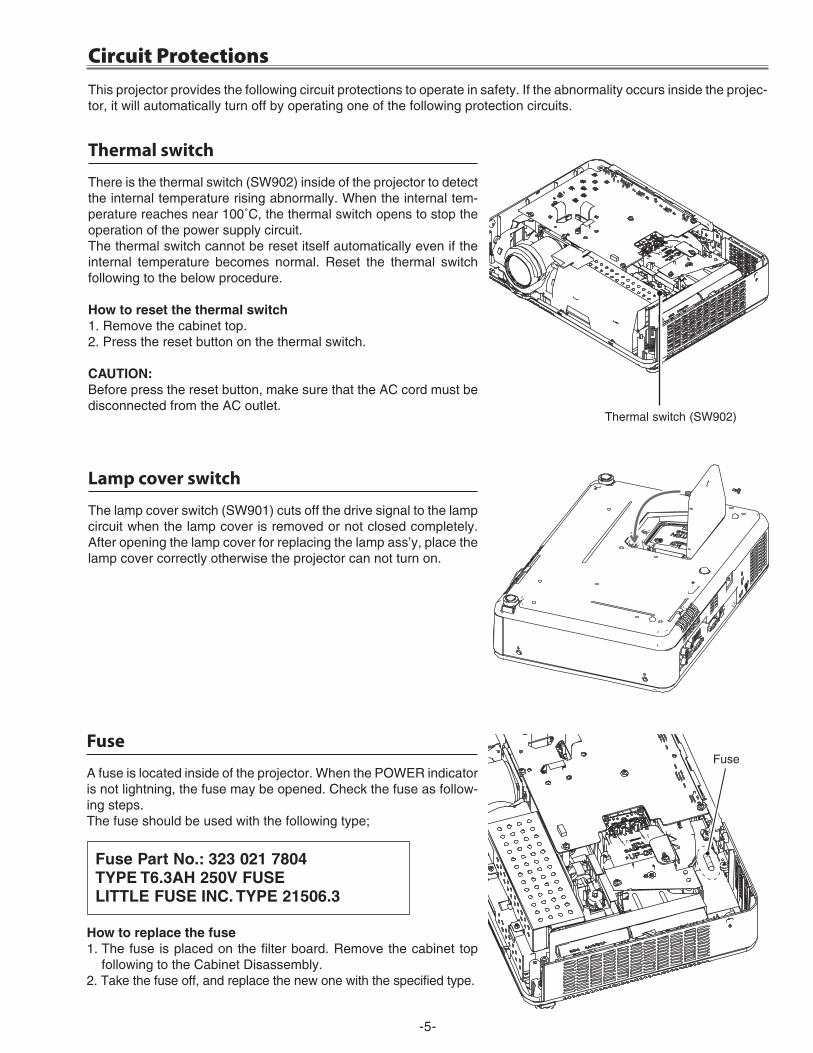
Fuse
A fuse is located inside of the projector. When the POWER indicator is not lightning, the fuse may be opened. Check the fuse as follow-ing steps.The fuse should be used with the following type;
Fuse Part No.: 323 021 7804 tYPe t6.3AH 250V FuSeLIttLe FuSe INc. tYPe 21506.3
How to replace the fuse1. The fuse is placed on the filter board. Remove the cabinet top
following to the Cabinet Disassembly. �. Take the fuse off, and replace the new one with the specified type.
Lamp cover switch
The lamp cover switch (SW901) cuts off the drive signal to the lamp circuit when the lamp cover is removed or not closed completely. After opening the lamp cover for replacing the lamp ass’y, place the lamp cover correctly otherwise the projector can not turn on.
Thermal switch
There is the thermal switch (SW90�) inside of the projector to detect the internal temperature rising abnormally. When the internal tem-perature reaches near 100˚C, the thermal switch opens to stop the operation of the power supply circuit.The thermal switch cannot be reset itself automatically even if the internal temperature becomes normal. Reset the thermal switch following to the below procedure.
How to reset the thermal switch1. Remove the cabinet top.�. Press the reset button on the thermal switch.
cAutIoN:Before press the reset button, make sure that the AC cord must be disconnected from the AC outlet.
This projector provides the following circuit protections to operate in safety. If the abnormality occurs inside the projec-tor, it will automatically turn off by operating one of the following protection circuits.
Thermal switch (SW90�)
Fuse
Circuit Protections
-6-
Circuit Protections
Warning temperature and power failure protection
The projector will be automatically turned off when the internal temperature of the projector is abnormally high, or the cooling fans stop spinning, or the power supplies in the projector are failed.- If the WARNING indicator is flashing, it may detect the abnormal temperature inside the projector. Check the follow-
ing possible causes and wait until the WARNING indicator stops flashing, and then try to turn on the projector. - If the WARNING indicator lights red, it may defect the cooling fans or power supply circuits. Check fans operation
and power supply lines referring to the chapter “Power supply & protection circuit” in the Chassis Block Diagram section.
Possible causes- Air filters are clogged with dust particles. Remove dust from the air filters by following instructions in the “Air filter
care and cleaning” below.- Ventilation slots of the projector are blocked. In such an event, reposition the projector so that ventilation slots are
not obstructed.- Check if projector is used at higher temperature place (Normal operating temperature is 5 to 35 ˚C or 41 to 95˚F)
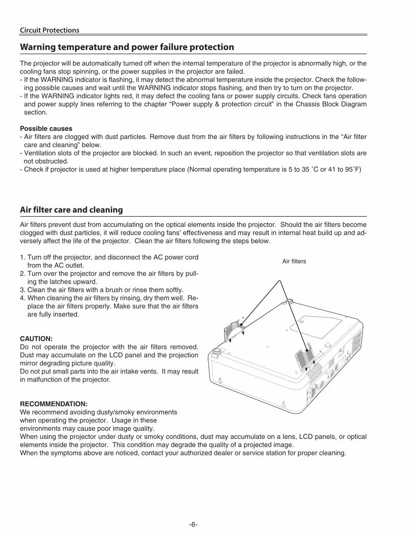
Air filter care and cleaning
Air filters prevent dust from accumulating on the optical elements inside the projector. Should the air filters become clogged with dust particles, it will reduce cooling fans’ effectiveness and may result in internal heat build up and ad-versely affect the life of the projector. Clean the air filters following the steps below.
1. Turn off the projector, and disconnect the AC power cord from the AC outlet.
�. Turn over the projector and remove the air filters by pull-ing the latches upward.
3. Clean the air filters with a brush or rinse them softly.4. When cleaning the air filters by rinsing, dry them well. Re-
place the air filters properly. Make sure that the air filters are fully inserted.
cAutIoN:Do not operate the projector with the air filters removed. Dust may accumulate on the LCD panel and the projection mirror degrading picture quality.Do not put small parts into the air intake vents. It may result in malfunction of the projector.
recoMMeNdAtIoN:We recommend avoiding dusty/smoky environments when operating the projector. Usage in theseenvironments may cause poor image quality.When using the projector under dusty or smoky conditions, dust may accumulate on a lens, LCD panels, or optical elements inside the projector. This condition may degrade the quality of a projected image. When the symptoms above are noticed, contact your authorized dealer or service station for proper cleaning.
Air filters
-7-
This projector provides security functions such as "Key lock", "PIN code lock" and "Logo PIN code lock". When the pro-jector has set these security function on, you are required to enter correct PIN code to use the projector. If you do not know the correct PIN code to the projector, the projector can no longer be operated or started. In this case, you must reset those function first according to the resetting procedure described below and then check up on the projector.
Security Function Notice
Resetting procedure1 Disconnect the AC power cord from the AC outlet.2 As pressing the SeLect button on the projector, connect the AC power cord into an AC outlet again. Keep
pressing the SeLect button until the POWER indicator lights continuously.
This is complete the resetting of the security function. The PIN code lock and Logo PIN code lock are reset as the initial PIN code at the factory and the Key lock function is disabled.
Please refer to the owner's manual for further information of the security functions.
Function description
Key lock
Locks operation of the top control or the remote con-trol.If the Key lock is enabled with top control lock, the pro-jector can no longer be started.
Initial setting: Key lock function is disabled
PIN code lockPrevents the projector from being operated by an un-authorized person.
Initial code: “1234”
Logo PIN code lockPrevents an unauthorized person for changing the start-up logo on the screen.
Initial code: “4321”
-8-
Lamp Replacement
How to check Lamp Used Time
The LAMP REPLACE indicator will light yellow when the total lamp used time (Corresponding value) reaches 3,000 hours. This is to indicate that lamp replacement is required.The total lamp used time is calculated by using the be-low expression,Total lamp used time = teco + tnormal x �
teco: used time in the Eco mode tnormal : used time in the Normal mode
You can check the lamp used time following to the below procedure.1 Press and hold the oN/StANd-BY button on the pro-
jector for more than �0 seconds.
2 The projector used time and lamp used time will be displayed on the screen briefly as follows.
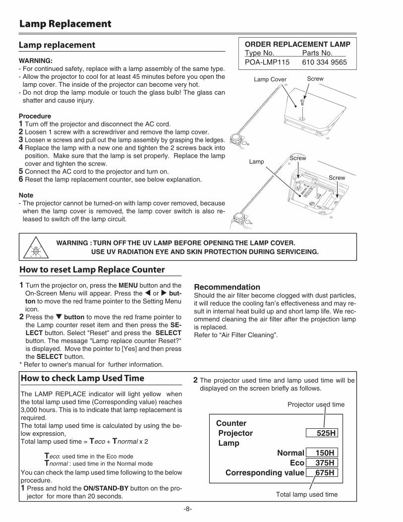
Lamp replacement
WArNING:- For continued safety, replace with a lamp assembly of the same type. - Allow the projector to cool for at least 45 minutes before you open the
lamp cover. The inside of the projector can become very hot.- Do not drop the lamp module or touch the glass bulb! The glass can
shatter and cause injury.
Procedure1 Turn off the projector and disconnect the AC cord. 2 Loosen 1 screw with a screwdriver and remove the lamp cover.3 Loosen w screws and pull out the lamp assembly by grasping the ledges.4 Replace the lamp with a new one and tighten the � screws back into
position. Make sure that the lamp is set properly. Replace the lamp cover and tighten the screw.
5 Connect the AC cord to the projector and turn on.6 Reset the lamp replacement counter, see below explanation.
Note- The projector cannot be turned-on with lamp cover removed, because
when the lamp cover is removed, the lamp cover switch is also re-leased to switch off the lamp circuit.
How to reset Lamp Replace Counter
1 Turn the projector on, press the MeNu button and the On-Screen Menu will appear. Press the 7 or 8 but-ton to move the red frame pointer to the Setting Menu icon.
2 Press the d button to move the red frame pointer to the Lamp counter reset item and then press the Se-Lect button. Select "Reset" and press the SeLect button. The message "Lamp replace counter Reset?" is displayed. Move the pointer to [Yes] and then press the SeLect button.
* Refer to owner's manual for further information.
recommendationShould the air filter become clogged with dust particles, it will reduce the cooling fan’s effectiveness and may re-sult in internal heat build up and short lamp life. We rec-ommend cleaning the air filter after the projection lamp is replaced.Refer to “Air Filter Cleaning”.
Lamp
Lamp Cover Screw
Screw
Counter Projector 525H Lamp Normal 150H Eco 375H Corresponding value 675H
Total lamp used time
Projector used time
order rePLAceMeNt LAMPType No. Parts No. POA-LMP115 610 334 9565
WArNING : turN oFF tHe uV LAMP BeFore oPeNING tHe LAMP coVer. uSe uV rAdIAtIoN eYe ANd SKIN ProtectIoN durING SerVIceING.
Screw
-9-
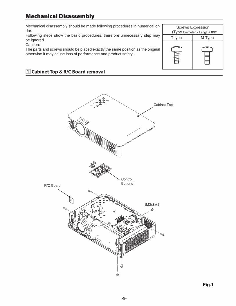
z Cabinet Top & R/C Board removal
Mechanical DisassemblyMechanical disassembly should be made following procedures in numerical or-der.Following steps show the basic procedures, therefore unnecessary step may be ignored.Caution: The parts and screws should be placed exactly the same position as the original otherwise it may cause loss of performance and product safety.
Screws Expression (Type Diameter x Length) mm
T type M Type
ControlButtons
R/C Board
Fig.1
(M3x8)x6
Cabinet Top
-10-
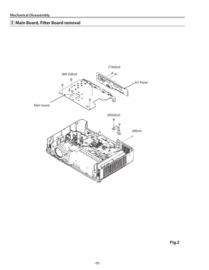
x Main Board, Filter Board removal
Mechanical Disassembly
Main board
AV Panel
Fig.2
(M�.5x8)x5
(M�x4)
(T3x6)x�
(M3x6)x�
-11-
Mechanical Disassembly
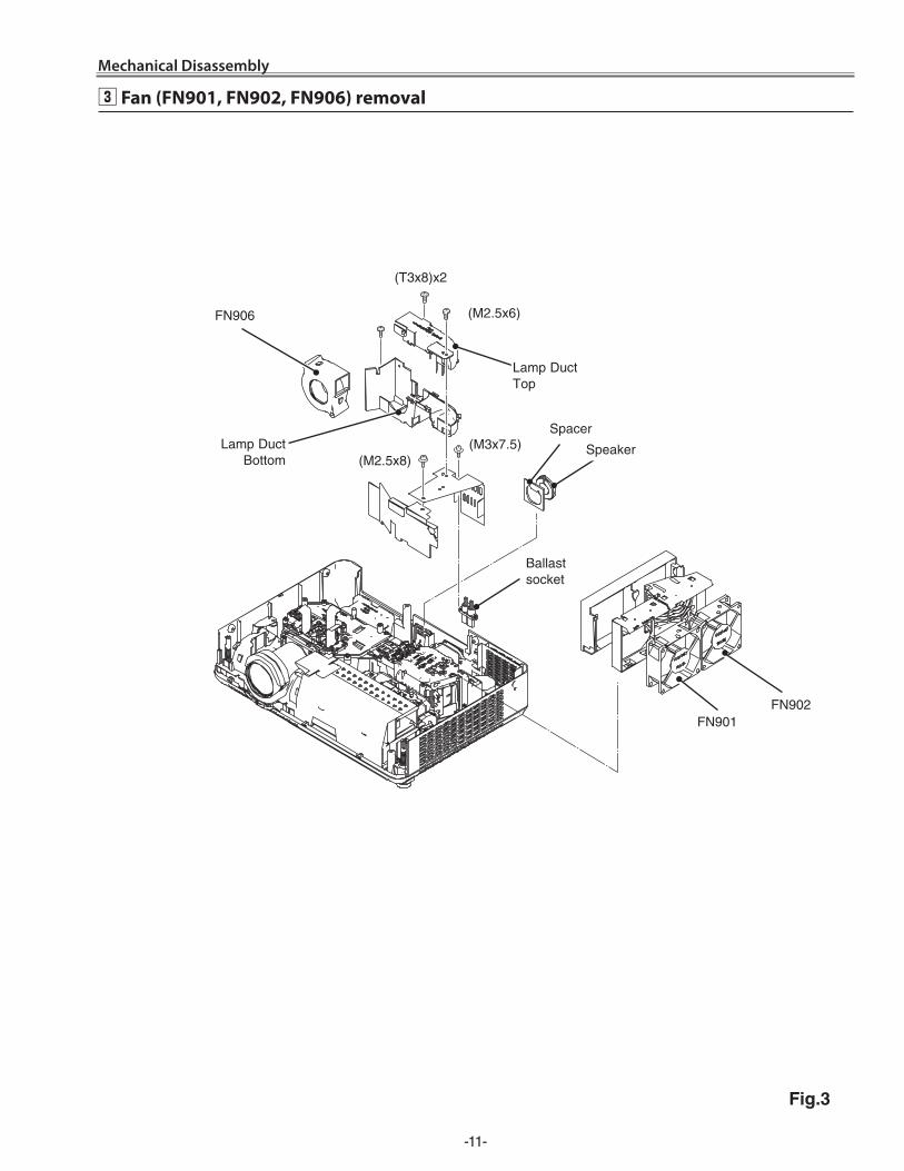
c Fan (FN901, FN902, FN906) removal
Fig.3
Lamp Duct Bottom
Spacer
Ballast socket
FN90�
FN906
FN901
(M�.5x8)(M3x7.5)
(T3x8)x�
(M�.5x6)
Lamp Duct Top
Speaker
-1�-
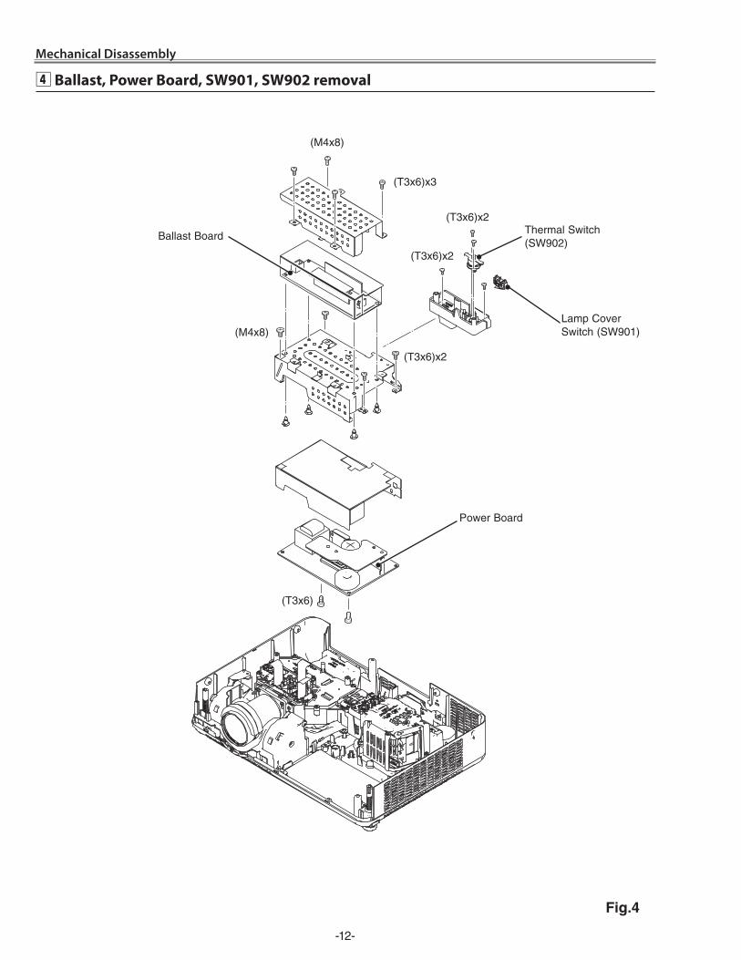
Mechanical Disassembly
Fig.4
v Ballast, Power Board, SW901, SW902 removal
Ballast Board Thermal Switch (SW90�)
(T3x6)x�
(T3x6)
(T3x6)x3
(M4x8)
(T3x6)x�
(M4x8)
(T3x6)x�
Lamp Cover Switch (SW901)
Power Board
-13-
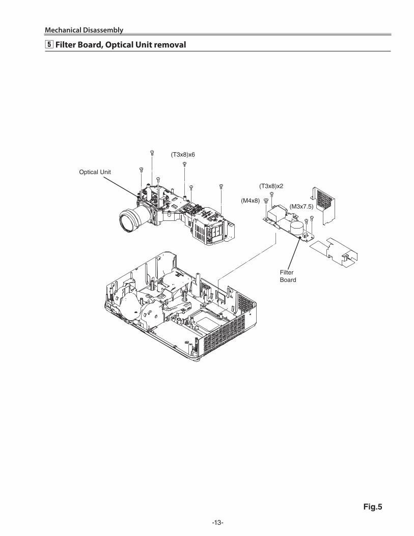
Mechanical Disassembly
Fig.5
b Filter Board, Optical Unit removal
Filter Board
Optical Unit
(T3x8)x6
(M4x8)
(T3x8)x�
(M3x7.5)
-14-
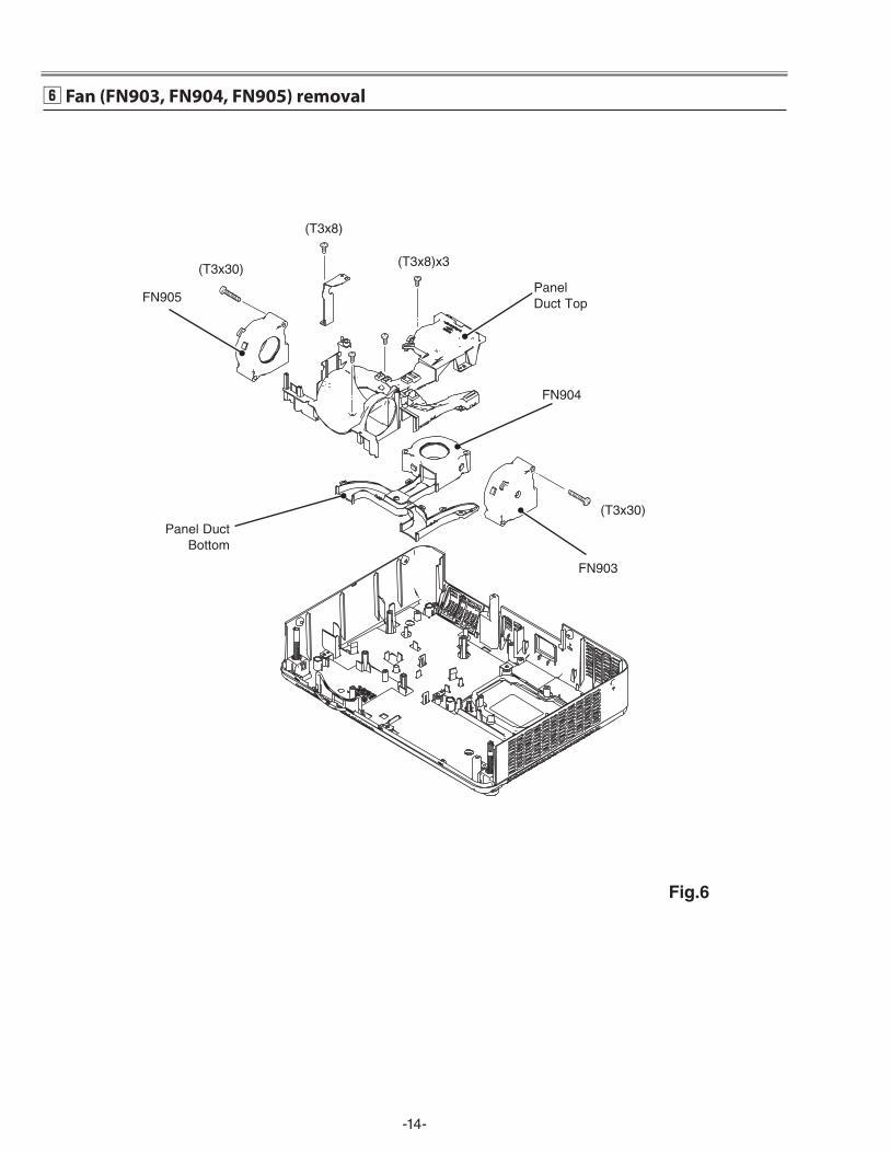
(T3x30)
(T3x30)
FN904
FN903
FN905
(T3x8)x3
(T3x8)
n Fan (FN903, FN904, FN905) removal
Panel Duct Top
Panel Duct Bottom
Fig.6
-15-
(M�.5x8)x4
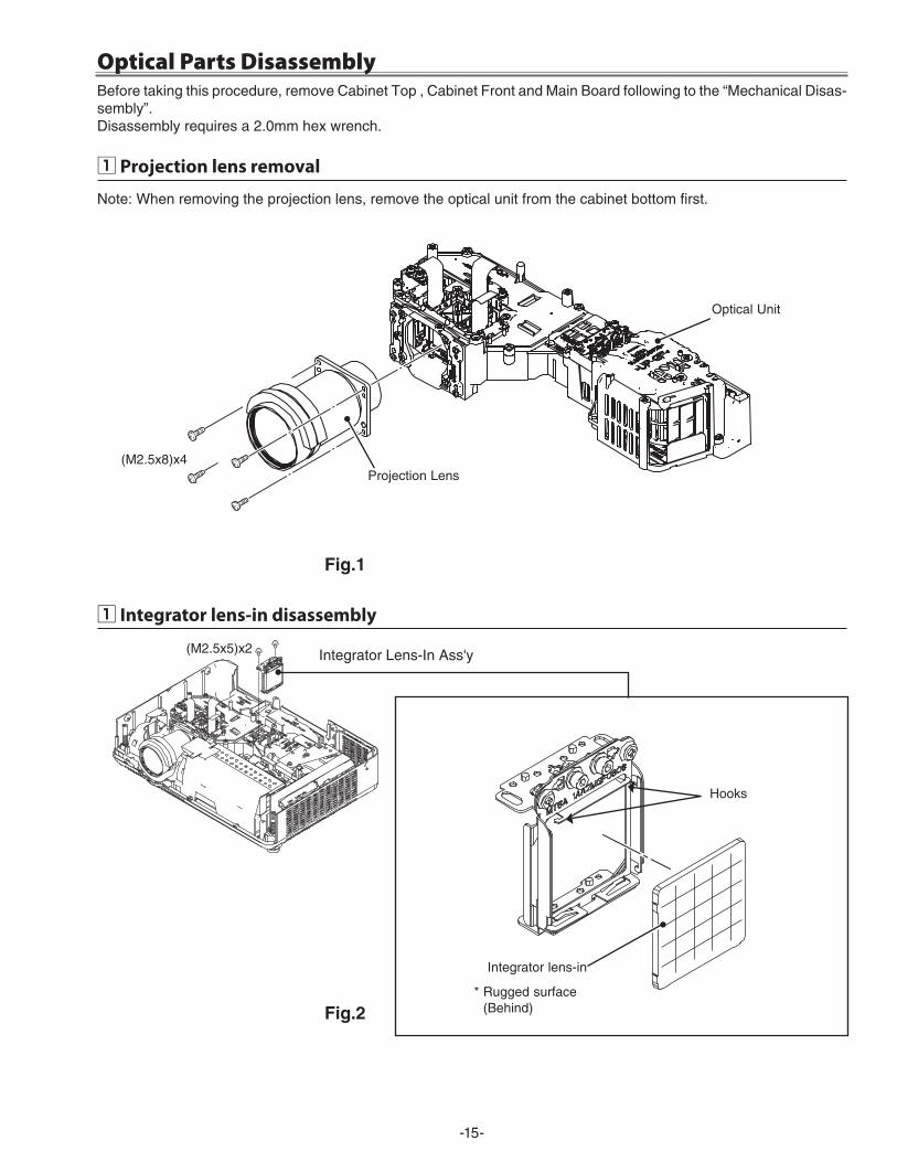
Optical Parts DisassemblyBefore taking this procedure, remove Cabinet Top , Cabinet Front and Main Board following to the “Mechanical Disas-sembly”.Disassembly requires a �.0mm hex wrench.
z Projection lens removal
Optical Unit
Projection Lens
Fig.1
z Integrator lens-in disassembly
Hooks
Integrator lens-in
Integrator Lens-In Ass'y(M�.5x5)x�
Fig.2* Rugged surface
(Behind)
Note: When removing the projection lens, remove the optical unit from the cabinet bottom first.
-16-
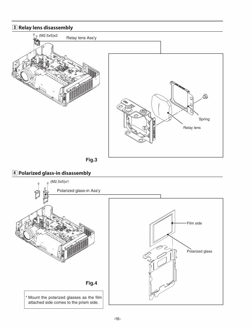
c Relay lens disassembly
Relay lens
Relay lens Ass'y(M�.5x5)x�
Spring
v Polarized glass-in disassembly
Polarized glass
Polarized glass-in Ass'y
(M�.5x5)x1
Film side
* Mount the polarized glasses as the film attached side comes to the prism side.
Fig.3
Fig.4
-17-
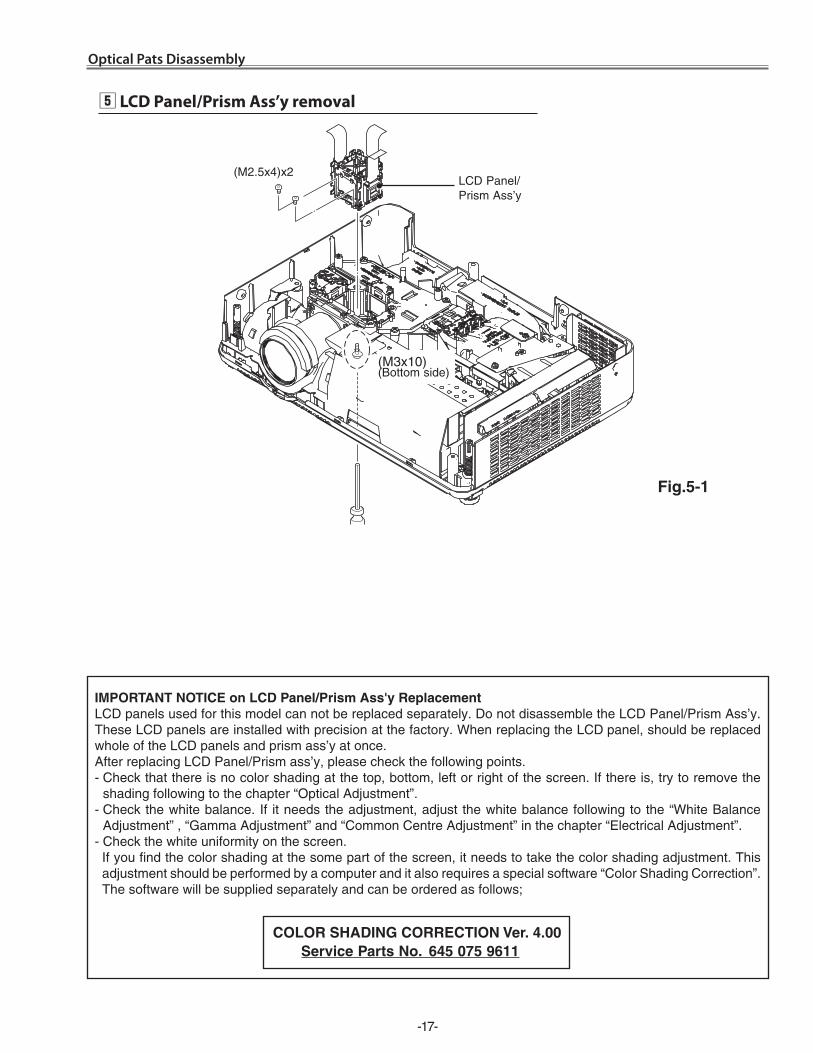
(M3x10)(Bottom side)
Optical Pats Disassembly
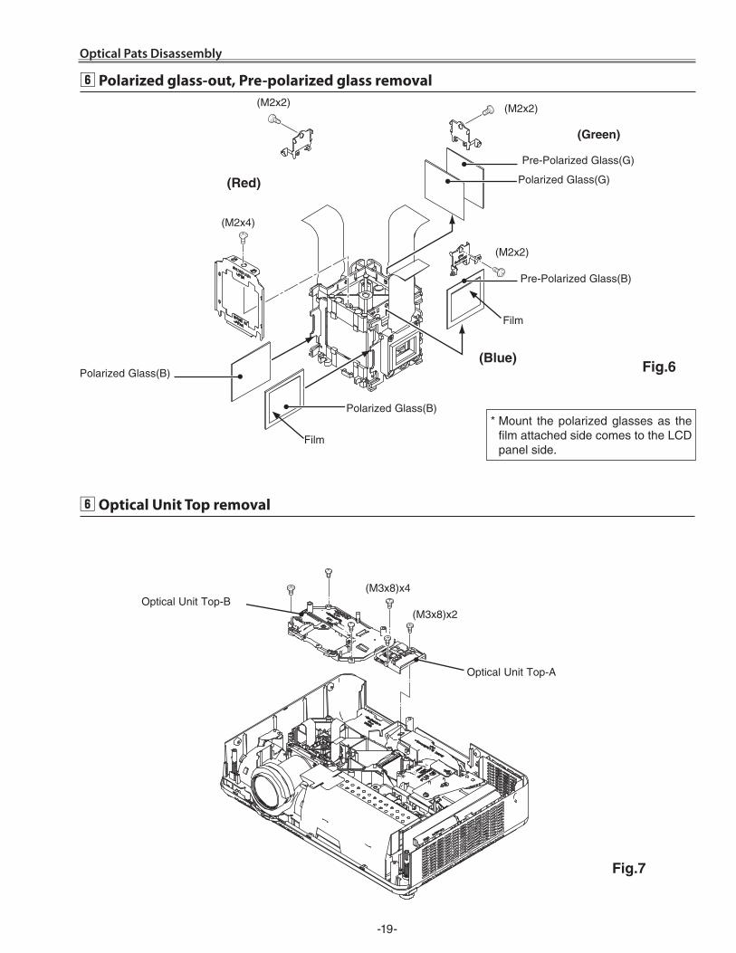
b LCD Panel/Prism Ass’y removal
LCD Panel/ Prism Ass’y
(M�.5x4)x�
IMPortANt NotIce on Lcd Panel/Prism Ass'y replacement LCD panels used for this model can not be replaced separately. Do not disassemble the LCD Panel/Prism Ass’y. These LCD panels are installed with precision at the factory. When replacing the LCD panel, should be replaced whole of the LCD panels and prism ass’y at once. After replacing LCD Panel/Prism ass’y, please check the following points.- Check that there is no color shading at the top, bottom, left or right of the screen. If there is, try to remove the
shading following to the chapter “Optical Adjustment”.- Check the white balance. If it needs the adjustment, adjust the white balance following to the “White Balance
Adjustment” , “Gamma Adjustment” and “Common Centre Adjustment” in the chapter “Electrical Adjustment”.- Check the white uniformity on the screen. If you find the color shading at the some part of the screen, it needs to take the color shading adjustment. This adjustment should be performed by a computer and it also requires a special software “Color Shading Correction”. The software will be supplied separately and can be ordered as follows;
coLor SHAdING correctIoN Ver. 4.00 Service Parts No. 645 075 9611
Fig.5-1
-18-
L3P06X-85G001-B-1234A1
-85G00
L3P06X-86G001-B-1234A1
-86G00
L3P06X-65G001-B-1234A1
-65G00
L3P06X-66G001-B-1234A1
-66G00
G-LCD PANEL
Optical Parts Disassembly
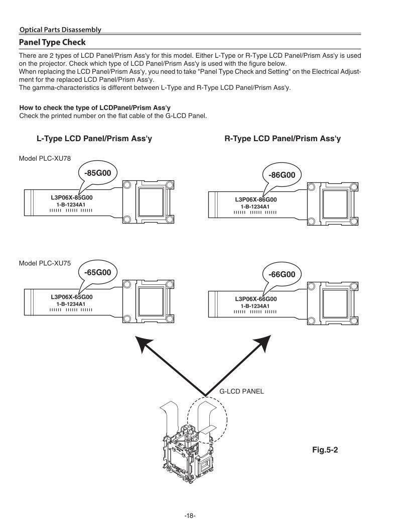
Panel Type CheckThere are � types of LCD Panel/Prism Ass'y for this model. Either L-Type or R-Type LCD Panel/Prism Ass'y is used on the projector. Check which type of LCD Panel/Prism Ass'y is used with the figure below.When replacing the LCD Panel/Prism Ass'y, you need to take "Panel Type Check and Setting" on the Electrical Adjust-ment for the replaced LCD Panel/Prism Ass'y.The gamma-characteristics is different between L-Type and R-Type LCD Panel/Prism Ass'y.
How to check the type of LcdPanel/Prism Ass'yCheck the printed number on the flat cable of the G-LCD Panel.
L-type Lcd Panel/Prism Ass'y r-type Lcd Panel/Prism Ass'y
Fig.5-2
Model PLC-XU78
Model PLC-XU75
-19-
(M3x8)x�
(M�x�) (M�x�)
(M�x�)
(Blue)
(red)
(M�x4)
Optical Pats Disassembly
n Polarized glass-out, Pre-polarized glass removal
Polarized Glass(G)
Pre-Polarized Glass(G)
* Mount the polarized glasses as the film attached side comes to the LCD panel side.
Film
(Green)
Pre-Polarized Glass(B)
Fig.6
n Optical Unit Top removal
Optical Unit Top-A
Polarized Glass(B)
Fig.7
Polarized Glass(B)
Film
Optical Unit Top-B(M3x8)x4
-�0-
5
8
1
6
9
2
3
4
7 7
10A
A
B
8
Fig.8
Optical Parts Disassembly
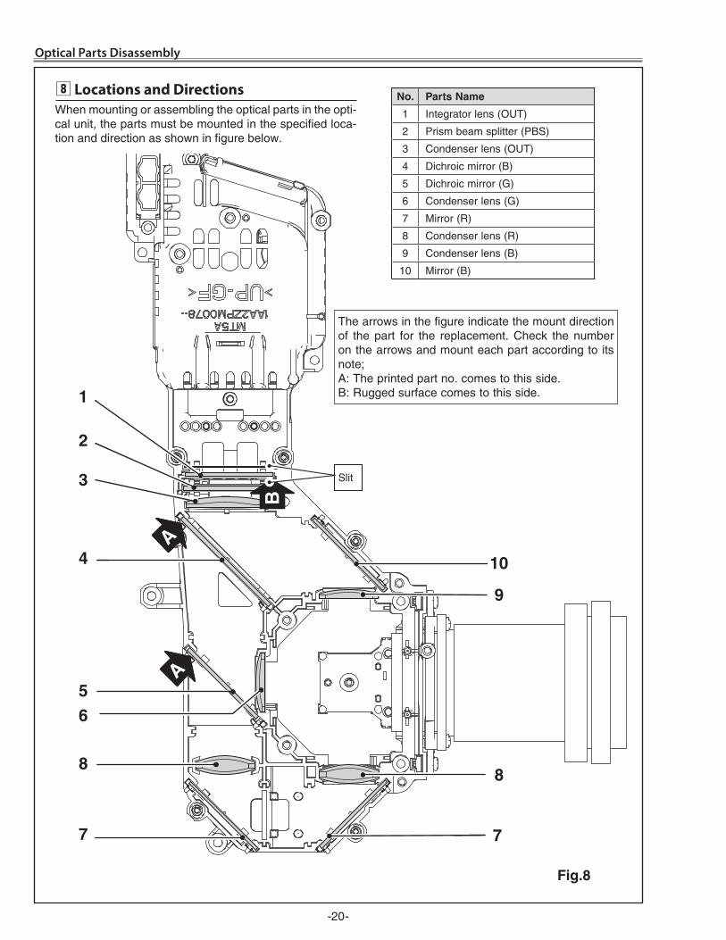
When mounting or assembling the optical parts in the opti-cal unit, the parts must be mounted in the specified loca-tion and direction as shown in figure below.
, Locations and Directions No. Parts Name
1 Integrator lens (OUT)
� Prism beam splitter (PBS)
3 Condenser lens (OUT)
4 Dichroic mirror (B)
5 Dichroic mirror (G)
6 Condenser lens (G)
7 Mirror (R)
8 Condenser lens (R)
9 Condenser lens (B)
10 Mirror (B)
5
8
1
6
9
2
3
4
7 7
10A
A
B
8
Slit
The arrows in the figure indicate the mount direction of the part for the replacement. Check the number on the arrows and mount each part according to its note;A: The printed part no. comes to this side.B: Rugged surface comes to this side.
-�1-
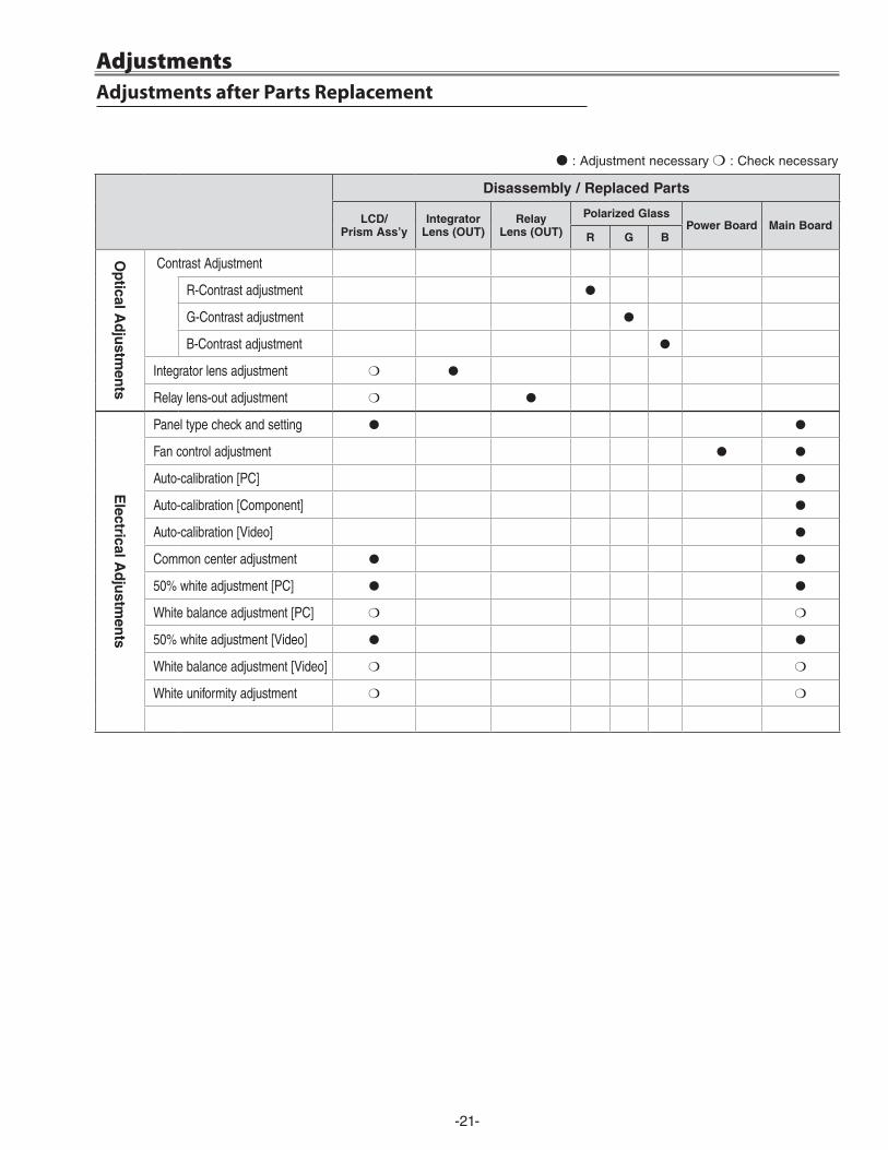
● : Adjustment necessary ❍ : Check necessary
Adjustments after Parts ReplacementAdjustments
disassembly / replaced Parts
Lcd/Prism Ass’y
IntegratorLens (out)
relayLens (out)
Polarized GlassPower Board Main Board
r G B
op
tical Ad
justm
ents
ContrastAdjustment
R-Contrastadjustment ●
G-Contrastadjustment ●
B-Contrastadjustment ●
Integratorlensadjustment ❍ ●
Relaylens-outadjustment ❍ ●
electrical A
dju
stmen
ts
Paneltypecheckandsetting ● ●
Fancontroladjustment ● ●
Auto-calibration[PC] ●
Auto-calibration[Component] ●
Auto-calibration[Video] ●
Commoncenteradjustment ● ●
50%whiteadjustment[PC] ● ●
Whitebalanceadjustment[PC] ❍ ❍
50%whiteadjustment[Video] ● ●
Whitebalanceadjustment[Video] ❍ ❍
Whiteuniformityadjustment ❍ ❍
-��-
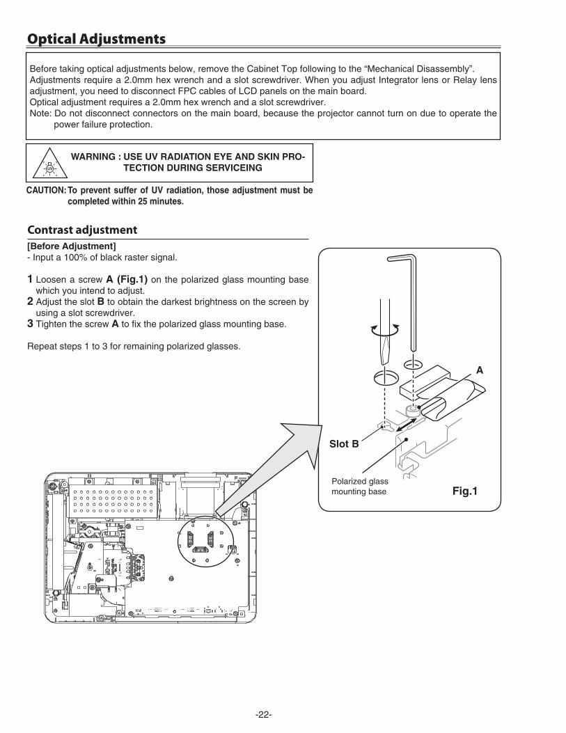
Optical Adjustments
[Before Adjustment]- Input a 100% of black raster signal.
1 Loosen a screw A (Fig.1) on the polarized glass mounting base which you intend to adjust.
2 Adjust the slot B to obtain the darkest brightness on the screen by using a slot screwdriver.
3 Tighten the screw A to fix the polarized glass mounting base.
Repeat steps 1 to 3 for remaining polarized glasses.
Fig.1Polarized glass mounting base
A
Contrast adjustment
Before taking optical adjustments below, remove the Cabinet Top following to the “Mechanical Disassembly”.Adjustments require a �.0mm hex wrench and a slot screwdriver. When you adjust Integrator lens or Relay lens adjustment, you need to disconnect FPC cables of LCD panels on the main board. Optical adjustment requires a �.0mm hex wrench and a slot screwdriver.Note: Do not disconnect connectors on the main board, because the projector cannot turn on due to operate the
power failure protection.
WArNING : uSe uV rAdIAtIoN eYe ANd SKIN Pro-tectIoN durING SerVIceING
cAutIoN: to prevent suffer of uV radiation, those adjustment must be completed within 25 minutes.
Slot B
-�3-
Optical Adjustments
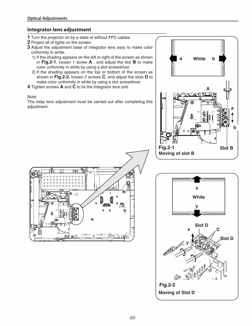
Fig.2-2
Moving of Slot d
Slot dc
y
x
White
Slot d
White
1 Turn the projector on by a state of without FPC cables.2 Project all of lights on the screen.3 Adjust the adjustment base of integrator lens assy to make color
uniformity in white. 1) If the shading appears on the left or right of the screen as shown
in Fig.2-1, loosen 1 screw A , and adjust the slot B to make color uniformity in white by using a slot screwdriver.
�) If the shading appears on the top or bottom of the screen as shown in Fig.2-2, loosen � screws c, and adjust the slots d to make color uniformity in white by using a slot screwdriver
4 Tighten screws A and c to fix the Integrator lens unit.
Note:The relay lens adjustment must be carried out after completing this adjustment.
Integrator lens adjustment
a
b
Moving of slot BFig.2-1 Slot B
A
a b
y
x
-�4-
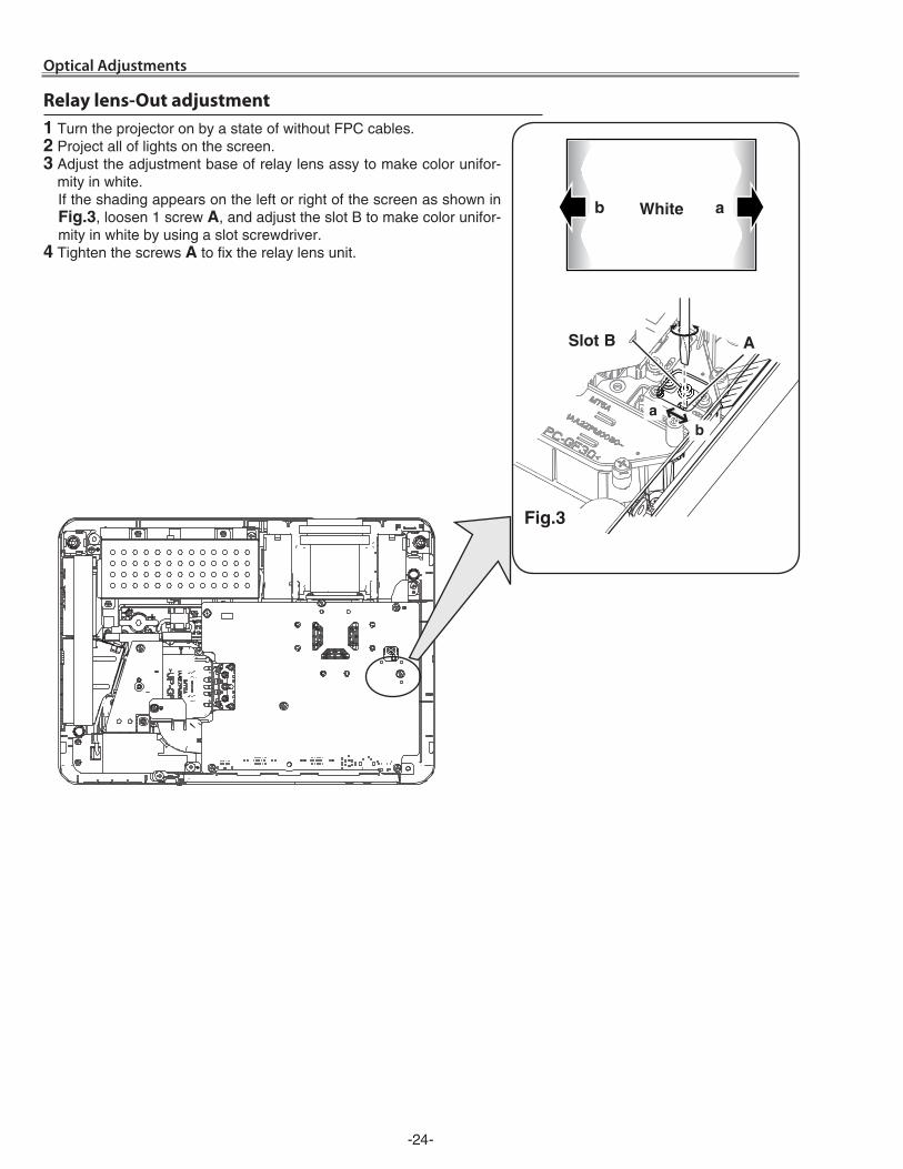
ab
Fig.3
ASlot B
b aWhite
1 Turn the projector on by a state of without FPC cables.2 Project all of lights on the screen.3 Adjust the adjustment base of relay lens assy to make color unifor-
mity in white.If the shading appears on the left or right of the screen as shown in Fig.3, loosen 1 screw A, and adjust the slot B to make color unifor-mity in white by using a slot screwdriver.
4 Tighten the screws A to fix the relay lens unit.
Relay lens-Out adjustment
Optical Adjustments
-�5-
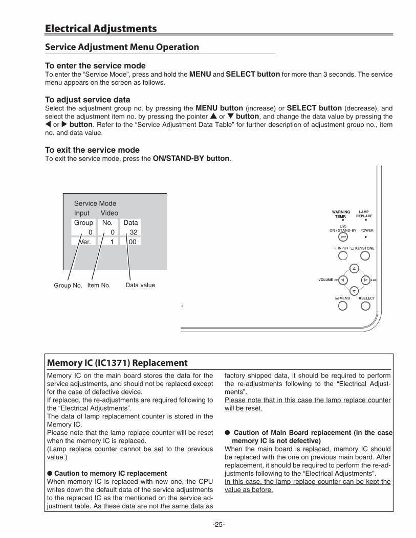
to enter the service modeTo enter the “Service Mode”, press and hold the MeNu and SeLect button for more than 3 seconds. The service menu appears on the screen as follows.
to adjust service dataSelect the adjustment group no. by pressing the MeNu button (increase) or SeLect button (decrease), and select the adjustment item no. by pressing the pointer e or d button, and change the data value by pressing the 7 or 8 button. Refer to the “Service Adjustment Data Table” for further description of adjustment group no., item no. and data value.
to exit the service modeTo exit the service mode, press the oN/StANd-BY button.
Service Adjustment Menu Operation
Memory IC on the main board stores the data for the service adjustments, and should not be replaced except for the case of defective device.If replaced, the re-adjustments are required following to the “Electrical Adjustments”.The data of lamp replacement counter is stored in the Memory IC.Please note that the lamp replace counter will be reset when the memory IC is replaced.(Lamp replace counter cannot be set to the previous value.)
● caution to memory Ic replacementWhen memory IC is replaced with new one, the CPU writes down the default data of the service adjustments to the replaced IC as the mentioned on the service ad-justment table. As these data are not the same data as
factory shipped data, it should be required to perform the re-adjustments following to the “Electrical Adjust-ments”.Please note that in this case the lamp replace counter will be reset.
● caution of Main Board replacement (in the case memory Ic is not defective)
When the main board is replaced, memory IC should be replaced with the one on previous main board. After replacement, it should be required to perform the re-ad-justments following to the “Electrical Adjustments”.In this case, the lamp replace counter can be kept the value as before.
Memory IC (IC1371) Replacement
Service ModeInput VideoGroup No. Data 0 0 32 Ver. 1 .00
Data valueItem No.
Electrical Adjustments
Group No.
-�6-
[Adjustment Condition] ● Input signal Video signal ....................... 1.0Vp-p/75W terminated, 16 steps gray scale
(Composite video signal) Computer signal ................... 0.7Vp-p/75W terminated, 16 steps gray scale
pattern Component Video signal ...... 0.7Vp-p/75W terminated, 16 steps gray scale
(Component video signal with 480p, 575p, 7�0p or 1080i format)
● Picture control mode ........ “STANDARD” mode unless otherwise not-ed.
Note:* Please refer to “Service Adjustment Menu Operation” for entering the service mode and adjusting the service data.
White 100% Black 100%
Circuit Adjustments
CAUTION: The each circuit has been made by the fine adjustment at factory. Do not attempt to adjust the following adjustments except requiring the readjustments in servicing otherwise it may cause loss of performance and product safety.
Electrical Adjustments
16 steps gray scale pattern
After replacing the Power Board readjust the Output volt-age adjustment as follows.
1. Connect a digital voltmeter to pins 1 (+) and 3 (-) of K6d.
�. Adjust the voltage by using VR611 as following.
AC Input Reading �30V 370V ±�V
Caution:Be sure to connect the lamp when taking this adjustment.* This adjustment is not required even if the power board
is replaced because this adjustment is carried out be-fore parts shipment.
Output Voltage adjustment* Before setting, you need to check which type of LCD pan-
el is placed on the projector according to the item "LCD Panel/Prism Ass'y removal" in the chapter "Optical Parts Disassembly".
1. Enter the service mode.�. Panel Type Check
Select group no. “290”, item no. “0”. Check the data value as follows;
Data value: 0 For L-Type of LCD Panel Data value: �0 For R-Type of LCD panel3. Panel Type Setting
Select group no. “290”, item no. “1” and change data value from 10 to 0 or �0 depending on your LCD Panel type. When the data value reaches 0 or �0, it returns to 10 quickly. The gamma-characteristics changes ac-cording to your selection.
Note:Be careful to take this adjustment. The value of gamma adjustment data will be reset and cannot be restored if you change the mode of LCD panel type.
z Panel Type Check and Setting
WArNING : uSe uV rAdIAtIoN eYe ANd SKIN ProtectIoN durING SerVIcING.
cAutIoN: to prevent suffer of uV radiation, those adjustments must be completed within 25 minutes.
-�7-
Electrical Adjustments
1. Enter the service mode.�. Receive the 16-step grey scale computer signal with
computer1 [rGB] mode.3. To start the auto-calibration for PC adjustment, select
group no. “260”, item no. “0” and then change data value from “0” to “1”. After the auto-calibration com-pleted, "OK" will appear on the screen.
c Auto Calibration adjustment [PC]1. Enter the service mode.�. Connect a digital voltmeter to test point “tPFANA” (+)
and chassis ground (-). Select group no. “250”, item no. “0” and change data value to adjust voltage to be 5.0 ±0.1V.
3. Connect a digital voltmeter to test point “tPFANB” (+) and chassis ground (-). Select item no. “2” and change data value to adjust voltage to be 5.0 ±0.1V.
4. Connect a digital voltmeter to test point “tPFANA” (+) and chassis ground (-). Select item no. “94” and change data value to adjust voltage to be 13.5 ±0.1V.
5. Connect a digital voltmeter to test point “tPFANB” (+) and chassis ground (-). Select item no. “96” and change data value to adjust voltage to be 13.5 ±0.1V.
x Fan Control adjustment
Pedestal adjustment [Pc]1. Enter the service mode.�. Receive the 16-step grey scale computer signal with
computer1 [rGB] mode.3. Connect an oscilloscope to test point “tP_G1” (+)
and chassis ground (-).4. Select group no. “0”, item no. “0” and change data
value to adjust the pedestal level and black level to be the same level.
5. Connect an oscilloscope to test point “tP_r1” (+) and chassis ground (-).
6. Select item no. “1” and change data value to adjust the pedestal level and black level to be the same level.
7. Connect an oscilloscope to test point “tP_B1” (+) and chassis ground (-).
8. Select item no. “2” and change data value to adjust the pedestal level and black level to be the same level.
Ped
esta
l Leb
elB
lack
Leb
el
Gain adjustment [Pc]1. Enter the service mode.�. Receive the 16-step grey scale computer signal with
computer1 [rGB] mode.3. Connect an oscilloscope to test point “tP35G” (+)
and chassis ground (-).4. Select group no. “0”, item no. “3” and adjust the ampli-
tude “a” to be minimum by changing the Data value.5. Connect an oscilloscope to test point “tP35r” (+) and
chassis ground (-).6. Select group no. “0”, item no. “4” and adjust the ampli-
tude “a” to be minimum by changing the Data value.7. Connect an oscilloscope to test point “tP35B” (+) and
chassis ground (-).8. Select group no. “0”, item no. “5” and adjust the ampli-
tude “a” to be minimum by changing the Data value.
(a)
White Level
Below adjustments are performed when the above auto calibration is failed.
-�8-
Electrical Adjustments
Gain adjustment [component]1. Enter the service mode.�. Receive the 16-step grey scale 480i-component signal
with computer1 [component] mode.3. Connect an oscilloscope to test point “tP_G1” (+) and
chassis ground (-).4. Select group no. “0”, item no. “3” and adjust the ampli-
tude “a” to be minimum by changing the Data value.
(a)
White Level
1. Enter the service mode.�. Receive the 16-step grey scale composite video sig-
nal with Video [Video] mode.3. To start the auto-calibration for Component adjust-
ment, select group no. “260”, item no. “0” and then change data value from “0” to “1”. After the auto-cali-bration completed, "OK" will appear on the screen.
b Auto Calibration adjustment [Video]
Gain adjustment [Video]1. Enter the service mode.�. Receive the 16-step grey scale composite video signal
with Video [Video] mode.3. Connect an oscilloscope to test point “tP_G1” (+) and
chassis ground (-).4. Select group no. “20”, item no. “0” and adjust the ampli-
tude “a” to be minimum by changing the Data value.
(a)
White Level
below adjustment is performed when the above auto calibration is failed.
Pedestal adjustment [component]1. Enter the service mode.�. Receive the 16-step grey scale 480i-component signal
with computer1 [component] mode.3. Connect an oscilloscope to test point “tP_G1” (+)
and chassis ground (-).4. Select group no. “0”, item no. “0” and change data
value to adjust the pedestal level and black level to be the same level.
5. Connect an oscilloscope to test point “tP_r1” (+) and chassis ground (-).
6. Select item no. “1” and change data value to adjust the pedestal level and black level to be the same level.
7. Connect an oscilloscope to test point “tP_B1” (+) and chassis ground (-).
8. Select item no. “2” and change data value to adjust the pedestal level and black level to be the same level.
Ped
esta
l Leb
elB
lack
Leb
el
1. Enter the service mode.�. Receive the 16-step grey scale 480i-component sig-
nal with computer1 [component] mode.3. To start the auto-calibration for Component adjust-
ment, select group no. “260”, item no. “0” and then change data value from “0” to “1”. After the auto-cali-bration completed, "OK" will appear on the screen.
Below adjustments are performed when the above auto calibration is failed.
v Auto Calibration adjustment [Component]
-�9-
1. Receive the 16-step grey scale composite video sig-nal with Video mode.
�. Enter the service mode.3. Connect an oscilloscope to test point “tP_G1” (+)
and chassis ground (-).4. Select group no. “100”, item no. “6” and change data
value to adjust amplitude “a” to be 2.2 ±0.1V.
(a)white level
white level
. 50% White adjustment [Video]
1. Receive the 16-step grey scale composite video sig-nal with Video mode.
�. Enter the service mode, select group no. “100” item no. “7” (Red) or “8” (Blue), and change Data values respectively to make a proper white balance.
Confirm that the same white balance is obtained in video and computer input.
⁄0 White Balance adjustment [Video]
Note On White Uniformity AdjustmentIf you find the color shading on the screen, please ad-just the white uniformity by using the proper computer and “Color Shading Correction” software supplied sep-arately.
The software can be ordered as follows;
coLor SHAdING correctIoN Ver. 4.00
Service Parts No. 645 075 9611
1. Enter the service mode, �. Receive the 16-step gray scale computer signal with
computer1 [rGB] mode.3. Select group no. “100” item no. “7” (Red) or “8” (Blue),
and change Data values respectively to make a prop-er white balance.
Confirm that the same white balance is obtained in video and computer input.
, White Balance adjustment [PC]
1. Enter the service mode.�. Receive the 16-step grey scale computer signal with
computer1 [rGB] mode.3. Connect an oscilloscope to test point “tP_G1” (+)
and chassis ground (-).4. Select group no. “100”, item no. “6” and change data
value to adjust amplitude “a” to be 1.6 ±0.1V.
(a)white level
white level
m 50% White adjustment [PC]
1. Enter the service mode.�. Receive the 50%-Whole Gray computer signal with
computer1 [rGB] mode.3. Select group no. “100”, item no. “92” and change
data value to “2” to reduce the panel frequency.4. Project only green light component to the screen.5. Select group no. “101”, item no. “1” and change
data value to obtain the minimum flicker on the screen.
6. Project only red light component to the screen.7. Select item no. “0” and change data value to obtain
the minimum flicker on the screen.8. Project only blue light component to the screen.9. Select item no. “2 and change data value to obtain
the minimum flicker on the screen.10. Select group no. “100”, item no. “92” and change
data value to “0” to reset the panel frequency.
n Common Center adjustment
-30-
K1
0A
K10B
K30B
K8
R
K2
0A
K20B
K4
0B
K801
IC5
61
K5B
K5
G
K5
R
K6B
K6JK6K
K6N
K6
RK
8D
K8F
K8
H
K8S
K4
06
IC501
IC5
31
TP
_G1
TP
_R1
TP
_B1
TP
FA
NA
TP
FA
NB
Electrical Adjustments
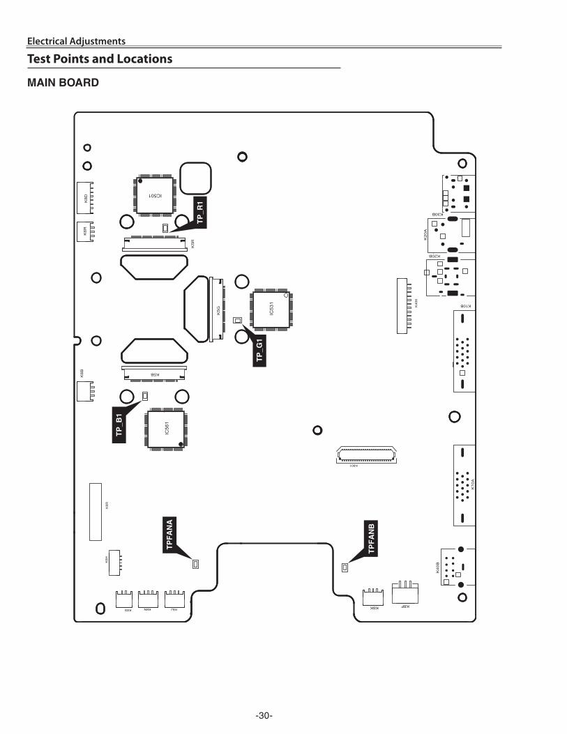
MAIN BoArd
Test Points and Locations
-31-
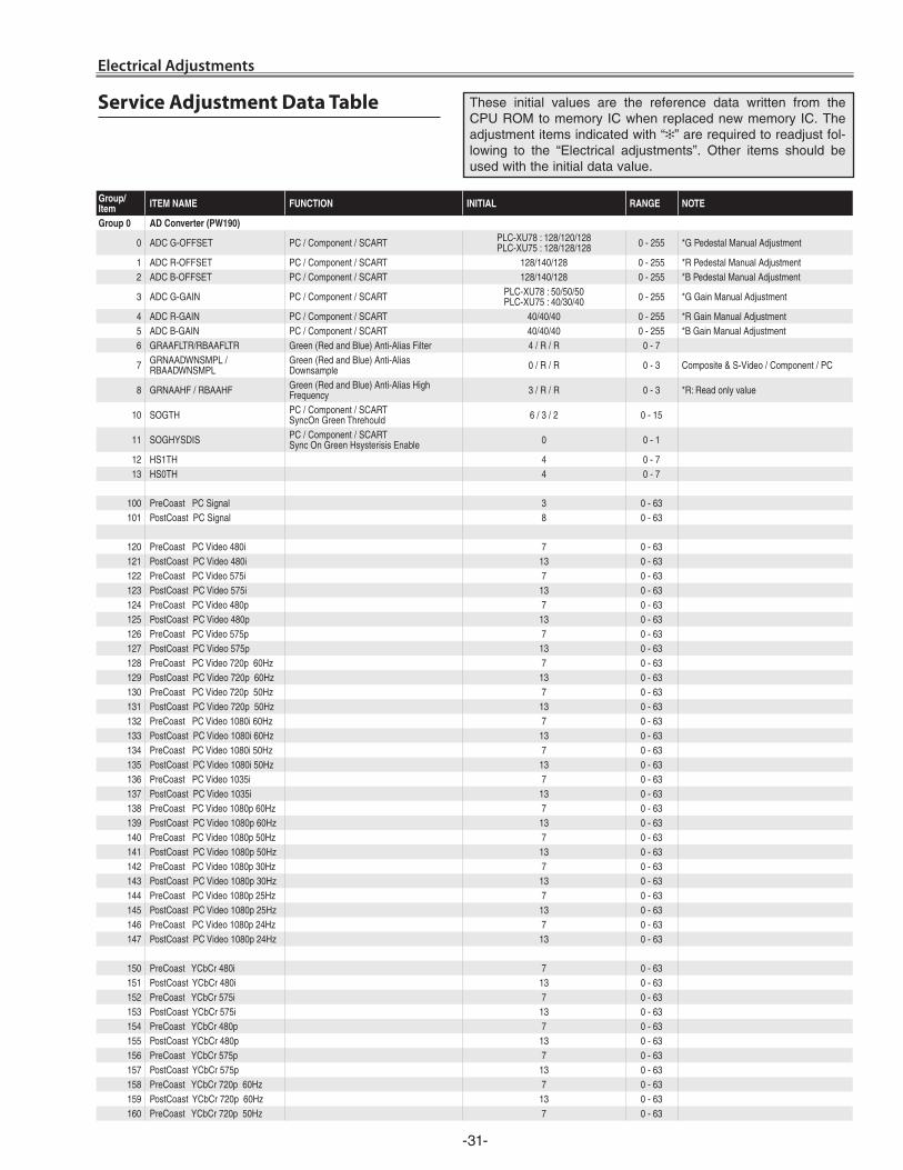
Electrical Adjustments
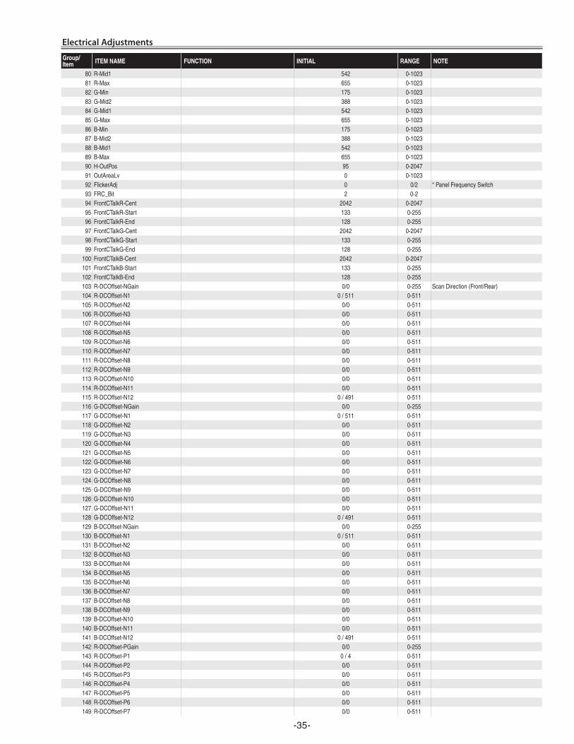
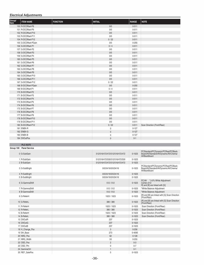
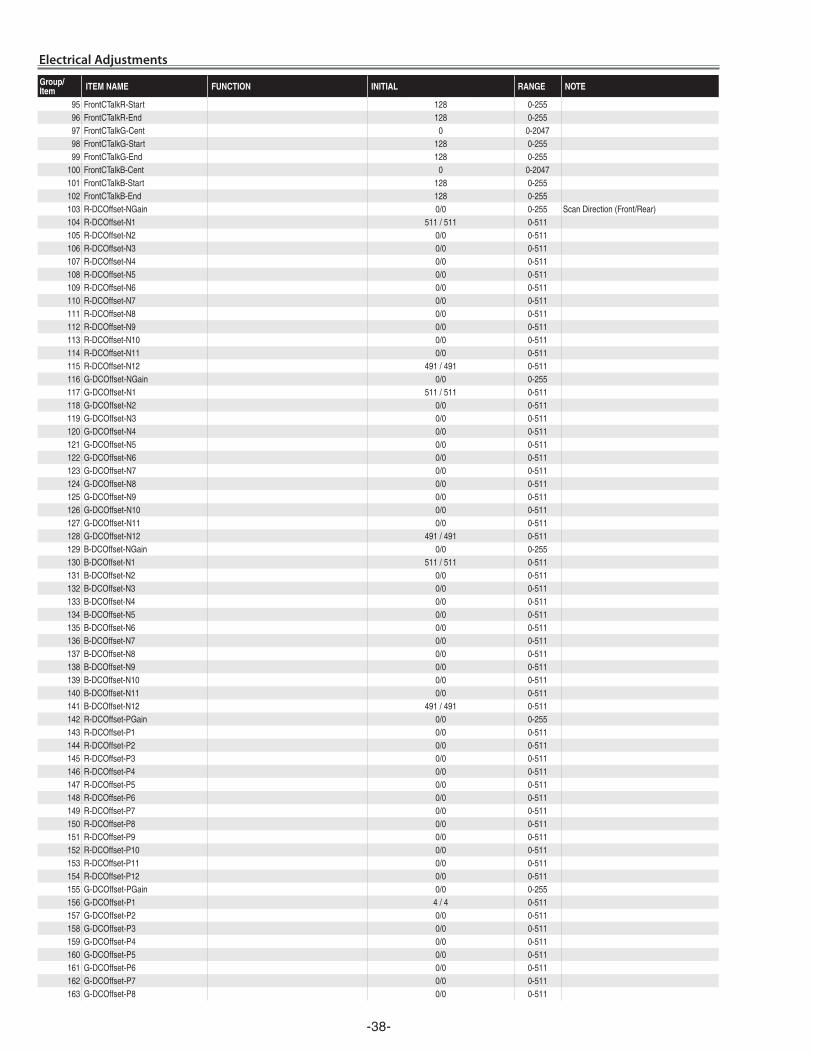
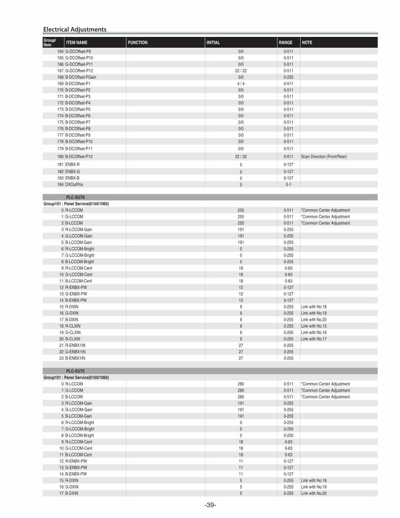
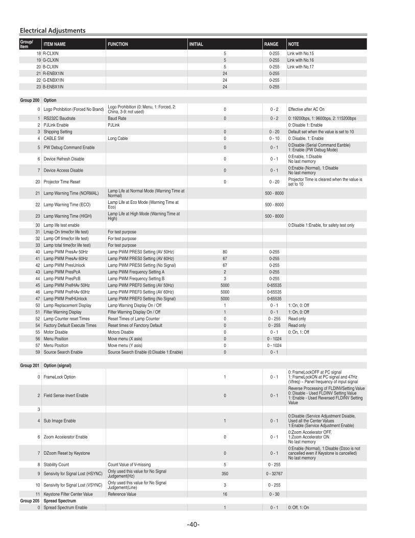
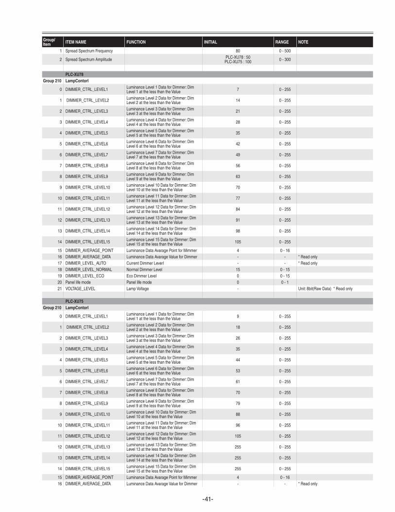
Service Adjustment Data Table These initial values are the reference data written from the CPU ROM to memory IC when replaced new memory IC. The adjustment items indicated with “✻” are required to readjust fol-lowing to the “Electrical adjustments”. Other items should be used with the initial data value.
Group/Item ITEM NAME FUNCTION INITIAL RANGE NOTE
Group 0 AD Converter (PW190)
0 ADCG-OFFSET PC/Component/SCART PLC-XU78:128/120/128PLC-XU75:128/128/128 0-255 *GPedestalManualAdjustment
1 ADCR-OFFSET PC/Component/SCART 128/140/128 0-255 *RPedestalManualAdjustment2 ADCB-OFFSET PC/Component/SCART 128/140/128 0-255 *BPedestalManualAdjustment
3 ADCG-GAIN PC/Component/SCART PLC-XU78:50/50/50PLC-XU75:40/30/40 0-255 *GGainManualAdjustment
4 ADCR-GAIN PC/Component/SCART 40/40/40 0-255 *RGainManualAdjustment5 ADCB-GAIN PC/Component/SCART 40/40/40 0-255 *BGainManualAdjustment6 GRAAFLTR/RBAAFLTR Green(RedandBlue)Anti-AliasFilter 4/R/R 0-7
7 GRNAADWNSMPL/RBAADWNSMPL
Green(RedandBlue)Anti-AliasDownsample 0/R/R 0-3 Composite&S-Video/Component/PC
8 GRNAAHF/RBAAHF Green(RedandBlue)Anti-AliasHighFrequency 3/R/R 0-3 *R:Readonlyvalue
10 SOGTH PC/Component/SCARTSyncOnGreenThrehould 6/3/2 0-15
11 SOGHYSDIS PC/Component/SCARTSyncOnGreenHsysterisisEnable 0 0-1
12 HS1TH 4 0-713 HS0TH 4 0-7
100 PreCoastPCSignal 3 0-63101 PostCoastPCSignal 8 0-63
120 PreCoastPCVideo480i 7 0-63121 PostCoastPCVideo480i 13 0-63122 PreCoastPCVideo575i 7 0-63123 PostCoastPCVideo575i 13 0-63124 PreCoastPCVideo480p 7 0-63125 PostCoastPCVideo480p 13 0-63126 PreCoastPCVideo575p 7 0-63127 PostCoastPCVideo575p 13 0-63128 PreCoastPCVideo720p60Hz 7 0-63129 PostCoastPCVideo720p60Hz 13 0-63130 PreCoastPCVideo720p50Hz 7 0-63131 PostCoastPCVideo720p50Hz 13 0-63132 PreCoastPCVideo1080i60Hz 7 0-63133 PostCoastPCVideo1080i60Hz 13 0-63134 PreCoastPCVideo1080i50Hz 7 0-63135 PostCoastPCVideo1080i50Hz 13 0-63136 PreCoastPCVideo1035i 7 0-63137 PostCoastPCVideo1035i 13 0-63138 PreCoastPCVideo1080p60Hz 7 0-63139 PostCoastPCVideo1080p60Hz 13 0-63140 PreCoastPCVideo1080p50Hz 7 0-63141 PostCoastPCVideo1080p50Hz 13 0-63142 PreCoastPCVideo1080p30Hz 7 0-63143 PostCoastPCVideo1080p30Hz 13 0-63144 PreCoastPCVideo1080p25Hz 7 0-63145 PostCoastPCVideo1080p25Hz 13 0-63146 PreCoastPCVideo1080p24Hz 7 0-63147 PostCoastPCVideo1080p24Hz 13 0-63
150 PreCoastYCbCr480i 7 0-63151 PostCoastYCbCr480i 13 0-63152 PreCoastYCbCr575i 7 0-63153 PostCoastYCbCr575i 13 0-63154 PreCoastYCbCr480p 7 0-63155 PostCoastYCbCr480p 13 0-63156 PreCoastYCbCr575p 7 0-63157 PostCoastYCbCr575p 13 0-63158 PreCoastYCbCr720p60Hz 7 0-63159 PostCoastYCbCr720p60Hz 13 0-63160 PreCoastYCbCr720p50Hz 7 0-63
-3�-
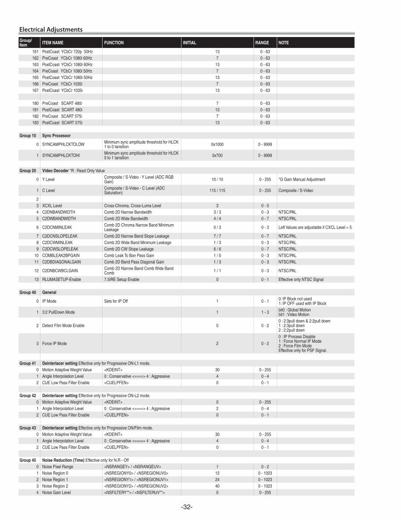
Electrical Adjustments
Group/Item ITEM NAME FUNCTION INITIAL RANGE NOTE
161 PostCoastYCbCr720p50Hz 13 0-63162 PreCoastYCbCr1080i60Hz 7 0-63163 PostCoastYCbCr1080i60Hz 13 0-63164 PreCoastYCbCr1080i50Hz 7 0-63165 PostCoastYCbCr1080i50Hz 13 0-63166 PreCoastYCbCr1035i 7 0-63167 PostCoastYCbCr1035i 13 0-63
180 PreCoastSCART480i 7 0-63181 PostCoastSCART480i 13 0-63182 PreCoastSCART575i 7 0-63183 PostCoastSCART575i 13 0-63
Group 10 Sync Processor
0 SYNCAMPHLCKTOLOW MinimumsyncamplitudethresholdforHLCK1to0tansition 0x1000 0-9999
1 SYNCAMPHLCKTOHI MinimumsyncamplitudethresholdforHLCK0to1tansition 0x700 0-9999
Group 20 Video Decoder *R:ReadOnlyValue
0 YLevel Composite/S-Video-YLevel(ADCRGBGain) 10/10 0-255 *GGainManualAdjustment
1 CLevel Composite/S-Video-CLevel(ADCSaturation) 115/115 0-255 Composite/S-Video
23 XCXLLevel Cross-Chroma,Cross-LumaLevel 3 0-54 C2DNBANDWIDTH Comb2DNarrowBandwidth 3/3 0-3 NTSC/PAL5 C2DWBANDWIDTH Comb2DWideBandwidth 4/4 0-7 NTSC/PAL
6 C2DCNMINLEAK Comb2DChromaNarrowBandMinimumLeakage 0/3 0-3 LeftValuesareadjustableifCXCLLevel=5.
7 C2DCNSLOPELEAK Comb2DNarrowBandSlopeLeakage 7/7 0-7 NTSC/PAL8 C2DCWMINLEAK Comb2DWideBandMinimumLeakage 1/3 0-3 NTSC/PAL9 C2DCWSLOPELEAK Comb2DCWSlopeLeakage 6/6 0-7 NTSC/PAL
10 COMBLEAK2BPGAIN CombLeakToBanPassGain 1/0 0-3 NTSC/PAL11 C2DBDIAGONALGAIN Comb2DBandPassDiagonalGain 1/3 0-3 NTSC/PAL
12 C2DNBCWBCLGAIN Comb2DNarrowBandCombWideBandComb 1/1 0-3 NTSC/PAL
13 RLUMASETUP-Enable 7.5IRESetupEnable 0 0-1 EffectiveonlyNTSCSignal
Group 40 General
0 IPMode SetsforIPOff 1 0-1 0:IPBlocknotused1:IPOFFusedwithIPBlock
1 3:2PullDownMode 1 1-3 bit0:GlobalMotionbit1:VideoMotion
2 DetectFilmModeEnable 0 0-20:2:3pulldown&2:2pulldown1:2:3pulldown2:2:2pulldown
3 ForceIPMode 2 0-2
0:IPProcessDisable1:ForceNormalIPMode2:ForceFilmModeEffectiveonlyforPSFSignal.
Group 41 Deinterlacer setting EffectiveonlyforProgressiveON-L1mode.0 MotionAdaptiveWeightValue <KDEINT> 30 0-2551 AngleInterpolationLevel 0:Conservative<====>4:Aggressive 4 0-42 CUELowPassFilterEnable <CUELPFEN> 0 0-1
Group 42 Deinterlacer setting EffectiveonlyforProgressiveON-L2mode.0 MotionAdaptiveWeightValue <KDEINT> 0 0-2551 AngleInterpolationLevel 0:Conservative<====>4:Aggressive 2 0-42 CUELowPassFilterEnable <CUELPFEN> 0 0-1
Group 43 Deinterlacer setting EffectiveonlyforProgressiveON/Filmmode.0 MotionAdaptiveWeightValue <KDEINT> 30 0-2551 AngleInterpolationLevel 0:Conservative<====>4:Aggressive 4 0-42 CUELowPassFilterEnable <CUELPFEN> 0 0-1
Group 45 Noise Reduction (Time) EffectiveonlyforN.R-Off0 NoisePixelRange <NSRANGEY>/<NSRANGEUV> 1 0-21 NoiseRegion0 <NSREGIONY0>/<NSREGIONUV0> 12 0-10232 NoiseRegion1 <NSREGIONY1>/<NSREGIONUV1> 24 0-10233 NoiseRegion2 <NSREGIONY2>/<NSREGIONUV2> 40 0-10234 NoiseGainLevel <NSFILTERY**>/<NSFILTERUV**> 0 0-255
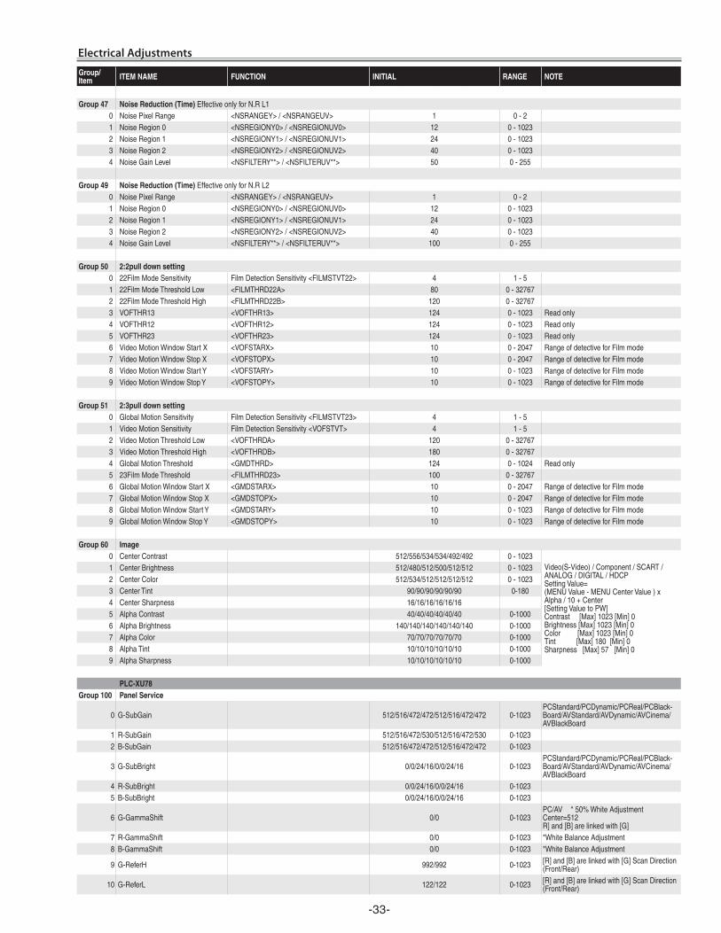
-33-
Electrical Adjustments
Group/Item ITEM NAME FUNCTION INITIAL RANGE NOTE
Group 47 Noise Reduction (Time) EffectiveonlyforN.RL10 NoisePixelRange <NSRANGEY>/<NSRANGEUV> 1 0-21 NoiseRegion0 <NSREGIONY0>/<NSREGIONUV0> 12 0-10232 NoiseRegion1 <NSREGIONY1>/<NSREGIONUV1> 24 0-10233 NoiseRegion2 <NSREGIONY2>/<NSREGIONUV2> 40 0-10234 NoiseGainLevel <NSFILTERY**>/<NSFILTERUV**> 50 0-255
Group 49 Noise Reduction (Time) EffectiveonlyforN.RL20 NoisePixelRange <NSRANGEY>/<NSRANGEUV> 1 0-21 NoiseRegion0 <NSREGIONY0>/<NSREGIONUV0> 12 0-10232 NoiseRegion1 <NSREGIONY1>/<NSREGIONUV1> 24 0-10233 NoiseRegion2 <NSREGIONY2>/<NSREGIONUV2> 40 0-10234 NoiseGainLevel <NSFILTERY**>/<NSFILTERUV**> 100 0-255
Group 50 2:2pull down setting0 22FilmModeSensitivity FilmDetectionSensitivity<FILMSTVT22> 4 1-51 22FilmModeThresholdLow <FILMTHRD22A> 80 0-327672 22FilmModeThresholdHigh <FILMTHRD22B> 120 0-327673 VOFTHR13 <VOFTHR13> 124 0-1023 Readonly4 VOFTHR12 <VOFTHR12> 124 0-1023 Readonly5 VOFTHR23 <VOFTHR23> 124 0-1023 Readonly6 VideoMotionWindowStartX <VOFSTARX> 10 0-2047 RangeofdetectiveforFilmmode7 VideoMotionWindowStopX <VOFSTOPX> 10 0-2047 RangeofdetectiveforFilmmode8 VideoMotionWindowStartY <VOFSTARY> 10 0-1023 RangeofdetectiveforFilmmode9 VideoMotionWindowStopY <VOFSTOPY> 10 0-1023 RangeofdetectiveforFilmmode
Group 51 2:3pull down setting0 GlobalMotionSensitivity FilmDetectionSensitivity<FILMSTVT23> 4 1-51 VideoMotionSensitivity FilmDetectionSensitivity<VOFSTVT> 4 1-52 VideoMotionThresholdLow <VOFTHRDA> 120 0-327673 VideoMotionThresholdHigh <VOFTHRDB> 180 0-327674 GlobalMotionThreshold <GMDTHRD> 124 0-1024 Readonly5 23FilmModeThreshold <FILMTHRD23> 100 0-327676 GlobalMotionWindowStartX <GMDSTARX> 10 0-2047 RangeofdetectiveforFilmmode7 GlobalMotionWindowStopX <GMDSTOPX> 10 0-2047 RangeofdetectiveforFilmmode8 GlobalMotionWindowStartY <GMDSTARY> 10 0-1023 RangeofdetectiveforFilmmode9 GlobalMotionWindowStopY <GMDSTOPY> 10 0-1023 RangeofdetectiveforFilmmode
Group 60 Image0 CenterContrast 512/556/534/534/492/492 0-1023
Video(S-Video)/Component/SCART/ANALOG/DIGITAL/HDCPSettingValue=(MENUValue-MENUCenterValue)xAlpha/10+Center[SettingValuetoPW]Contrast[Max]1023[Min]0Brightness[Max]1023[Min]0Color[Max]1023[Min]0Tint[Max]180[Min]0Sharpness[Max]57[Min]0
1 CenterBrightness 512/480/512/500/512/512 0-10232 CenterColor 512/534/512/512/512/512 0-10233 CenterTint 90/90/90/90/90/90 0-1804 CenterSharpness 16/16/16/16/16/165 AlphaContrast 40/40/40/40/40/40 0-10006 AlphaBrightness 140/140/140/140/140/140 0-10007 AlphaColor 70/70/70/70/70/70 0-10008 AlphaTint 10/10/10/10/10/10 0-10009 AlphaSharpness 10/10/10/10/10/10 0-1000
PLC-XU78Group 100 Panel Service
0 G-SubGain 512/516/472/472/512/516/472/472 0-1023PCStandard/PCDynamic/PCReal/PCBlack-Board/AVStandard/AVDynamic/AVCinema/AVBlackBoard
1 R-SubGain 512/516/472/530/512/516/472/530 0-10232 B-SubGain 512/516/472/472/512/516/472/472 0-1023
3 G-SubBright 0/0/24/16/0/0/24/16 0-1023PCStandard/PCDynamic/PCReal/PCBlack-Board/AVStandard/AVDynamic/AVCinema/AVBlackBoard
4 R-SubBright 0/0/24/16/0/0/24/16 0-10235 B-SubBright 0/0/24/16/0/0/24/16 0-1023
6 G-GammaShift 0/0 0-1023PC/AV *50%WhiteAdjustmentCenter=512R]and[B]arelinkedwith[G]
7 R-GammaShift 0/0 0-1023 *WhiteBalanceAdjustment8 B-GammaShift 0/0 0-1023 *WhiteBalanceAdjustment
9 G-ReferH 992/992 0-1023 [R]and[B]arelinkedwith[G]ScanDirection(Front/Rear)
10 G-ReferL 122/122 0-1023 [R]and[B]arelinkedwith[G]ScanDirection(Front/Rear)
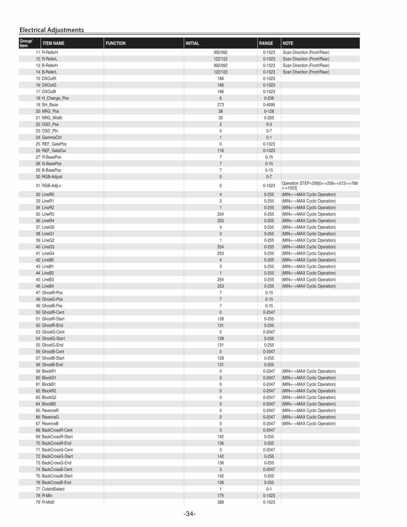
-34-
Electrical Adjustments
Group/Item ITEM NAME FUNCTION INITIAL RANGE NOTE
11 R-ReferH 992/992 0-1023 ScanDirection(Front/Rear)12 R-ReferL 122/122 0-1023 ScanDirection(Front/Rear)13 B-ReferH 992/992 0-1023 ScanDirection(Front/Rear)14 B-ReferL 122/122 0-1023 ScanDirection(Front/Rear)15 DXOutR 186 0-102316 DXOutG 186 0-102317 DXOutB 186 0-102318 H_Change_Pos 6 0-25619 SH_Base 273 0-409520 NRG_Pos 38 0-12821 NRG_Width 30 0-25522 OSD_Pos 2 0-323 OSD_Ptn 0 0-724 GammaCtrl 1 0-125 REF_GatePos 0 0-102326 REF_GateDur 116 0-102327 R-BasePos 7 0-1528 G-BasePos 7 0-1529 B-BasePos 7 0-1530 RGB-Adjust 0 0-7
31 RGB-AdjLv 0 0-1023 OperationSTEP=256[0<->256<->512<->768<->1023]
32 LineR0 4 0-255 (MIN<-->MAXCyclicOperation)33 LineR1 3 0-255 (MIN<-->MAXCyclicOperation)34 LineR2 1 0-255 (MIN<-->MAXCyclicOperation)35 LineR3 254 0-255 (MIN<-->MAXCyclicOperation)36 LineR4 253 0-255 (MIN<-->MAXCyclicOperation)37 LineG0 4 0-255 (MIN<-->MAXCyclicOperation)38 LineG1 3 0-255 (MIN<-->MAXCyclicOperation)39 LineG2 1 0-255 (MIN<-->MAXCyclicOperation)40 LineG3 254 0-255 (MIN<-->MAXCyclicOperation)41 LineG4 253 0-255 (MIN<-->MAXCyclicOperation)42 LineB0 4 0-255 (MIN<-->MAXCyclicOperation)43 LineB1 3 0-255 (MIN<-->MAXCyclicOperation)44 LineB2 1 0-255 (MIN<-->MAXCyclicOperation)45 LineB3 254 0-255 (MIN<-->MAXCyclicOperation)46 LineB4 253 0-255 (MIN<-->MAXCyclicOperation)47 GhostR-Pos 7 0-1548 GhostG-Pos 7 0-1549 GhostB-Pos 7 0-1550 GhostR-Cent 0 0-204751 GhostR-Start 128 0-25552 GhostR-End 131 0-25553 GhostG-Cent 0 0-204754 GhostG-Start 128 0-25555 GhostG-End 131 0-25556 GhostB-Cent 0 0-204757 GhostB-Start 128 0-25558 GhostB-End 131 0-25559 BlockR1 0 0-2047 (MIN<-->MAXCyclicOperation)60 BlockG1 0 0-2047 (MIN<-->MAXCyclicOperation)61 BlockB1 0 0-2047 (MIN<-->MAXCyclicOperation)62 BlockR2 0 0-2047 (MIN<-->MAXCyclicOperation)63 BlockG2 0 0-2047 (MIN<-->MAXCyclicOperation)64 BlockB2 0 0-2047 (MIN<-->MAXCyclicOperation)65 ReverceR 0 0-2047 (MIN<-->MAXCyclicOperation)66 ReverceG 0 0-2047 (MIN<-->MAXCyclicOperation)67 ReverceB 0 0-2047 (MIN<-->MAXCyclicOperation)68 BackCrossR-Cent 3 0-204769 BackCrossR-Start 142 0-25570 BackCrossR-End 136 0-25571 BackCrossG-Cent 3 0-204772 BackCrossG-Start 142 0-25573 BackCrossG-End 136 0-25574 BackCrossB-Cent 3 0-204775 BackCrossB-Start 142 0-25576 BackCrossB-End 136 0-25577 ColshdSelect 1 0-178 R-Min 175 0-102379 R-Mid2 388 0-1023
-35-
Electrical Adjustments
Group/Item ITEM NAME FUNCTION INITIAL RANGE NOTE
80 R-Mid1 542 0-102381 R-Max 655 0-102382 G-Min 175 0-102383 G-Mid2 388 0-102384 G-Mid1 542 0-102385 G-Max 655 0-102386 B-Min 175 0-102387 B-Mid2 388 0-102388 B-Mid1 542 0-102389 B-Max 655 0-102390 H-OutPos 95 0-204791 OutAreaLv 0 0-102392 FlickerAdj 0 0/2 *PanelFrequencySwitch93 FRC_Bit 2 0-294 FrontCTalkR-Cent 2042 0-204795 FrontCTalkR-Start 133 0-25596 FrontCTalkR-End 128 0-25597 FrontCTalkG-Cent 2042 0-204798 FrontCTalkG-Start 133 0-25599 FrontCTalkG-End 128 0-255
100 FrontCTalkB-Cent 2042 0-2047101 FrontCTalkB-Start 133 0-255102 FrontCTalkB-End 128 0-255103 R-DCOffset-NGain 0/0 0-255 ScanDirection(Front/Rear)104 R-DCOffset-N1 0/511 0-511105 R-DCOffset-N2 0/0 0-511106 R-DCOffset-N3 0/0 0-511107 R-DCOffset-N4 0/0 0-511108 R-DCOffset-N5 0/0 0-511109 R-DCOffset-N6 0/0 0-511110 R-DCOffset-N7 0/0 0-511111 R-DCOffset-N8 0/0 0-511112 R-DCOffset-N9 0/0 0-511113 R-DCOffset-N10 0/0 0-511114 R-DCOffset-N11 0/0 0-511115 R-DCOffset-N12 0/491 0-511116 G-DCOffset-NGain 0/0 0-255117 G-DCOffset-N1 0/511 0-511118 G-DCOffset-N2 0/0 0-511119 G-DCOffset-N3 0/0 0-511120 G-DCOffset-N4 0/0 0-511121 G-DCOffset-N5 0/0 0-511122 G-DCOffset-N6 0/0 0-511123 G-DCOffset-N7 0/0 0-511124 G-DCOffset-N8 0/0 0-511125 G-DCOffset-N9 0/0 0-511126 G-DCOffset-N10 0/0 0-511127 G-DCOffset-N11 0/0 0-511128 G-DCOffset-N12 0/491 0-511129 B-DCOffset-NGain 0/0 0-255130 B-DCOffset-N1 0/511 0-511131 B-DCOffset-N2 0/0 0-511132 B-DCOffset-N3 0/0 0-511133 B-DCOffset-N4 0/0 0-511134 B-DCOffset-N5 0/0 0-511135 B-DCOffset-N6 0/0 0-511136 B-DCOffset-N7 0/0 0-511137 B-DCOffset-N8 0/0 0-511138 B-DCOffset-N9 0/0 0-511139 B-DCOffset-N10 0/0 0-511140 B-DCOffset-N11 0/0 0-511141 B-DCOffset-N12 0/491 0-511142 R-DCOffset-PGain 0/0 0-255143 R-DCOffset-P1 0/4 0-511144 R-DCOffset-P2 0/0 0-511145 R-DCOffset-P3 0/0 0-511146 R-DCOffset-P4 0/0 0-511147 R-DCOffset-P5 0/0 0-511148 R-DCOffset-P6 0/0 0-511149 R-DCOffset-P7 0/0 0-511
-36-
Electrical Adjustments
Group/Item ITEM NAME FUNCTION INITIAL RANGE NOTE
150 R-DCOffset-P8 0/0 0-511151 R-DCOffset-P9 0/0 0-511152 R-DCOffset-P10 0/0 0-511153 R-DCOffset-P11 0/0 0-511154 R-DCOffset-P12 0/22 0-511155 G-DCOffset-PGain 0/0 0-255156 G-DCOffset-P1 0/4 0-511157 G-DCOffset-P2 0/0 0-511158 G-DCOffset-P3 0/0 0-511159 G-DCOffset-P4 0/0 0-511160 G-DCOffset-P5 0/0 0-511161 G-DCOffset-P6 0/0 0-511162 G-DCOffset-P7 0/0 0-511163 G-DCOffset-P8 0/0 0-511164 G-DCOffset-P9 0/0 0-511165 G-DCOffset-P10 0/0 0-511166 G-DCOffset-P11 0/0 0-511167 G-DCOffset-P12 0/22 0-511168 B-DCOffset-PGain 0/0 0-255169 B-DCOffset-P1 0/4 0-511170 B-DCOffset-P2 0/0 0-511171 B-DCOffset-P3 0/0 0-511172 B-DCOffset-P4 0/0 0-511173 B-DCOffset-P5 0/0 0-511174 B-DCOffset-P6 0/0 0-511175 B-DCOffset-P7 0/0 0-511176 B-DCOffset-P8 0/0 0-511177 B-DCOffset-P9 0/0 0-511178 B-DCOffset-P10 0/0 0-511179 B-DCOffset-P11 0/0 0-511180 B-DCOffset-P12 0/22 0-511 ScanDirection(Front/Rear)181 ENBX-R 0 0-127182 ENBX-G 0 0-127183 ENBX-B 0 0-127 184 DXOutPos 0 0-1
PLC-XU75Group 100 Panel Service
0 G-SubGain 512/516/472/472/512/516/472/472 0-1023PCStandard/PCDynamic/PCReal/PCBlack-Board/AVStandard/AVDynamic/AVCinema/AVBlackBoard
1 R-SubGain 512/516/472/530/512/516/472/530 0-10232 B-SubGain 512/516/472/472/512/516/472/472 0-1023
3 G-SubBright 0/0/24/16/0/0/24/16 0-1023PCStandard/PCDynamic/PCReal/PCBlack-Board/AVStandard/AVDynamic/AVCinema/AVBlackBoard
4 R-SubBright 0/0/24/16/0/0/24/16 0-10235 B-SubBright 0/0/24/16/0/0/24/16 0-1023
6 G-GammaShift 512/512 0-1023PC/AV *5-0%WhiteAdjustmentCenter=512R]and[B]arelinkedwith[G]
7 R-GammaShift 512/512 0-1023 *WhiteBalanceAdjustment8 B-GammaShift 512/512 0-1023 *WhiteBalanceAdjustment
9 G-ReferH 1023/1023 0-1023 [R]and[B]arelinkedwith[G]ScanDirection(Front/Rear)
10 G-ReferL 380/380 0-1023 [R]and[B]arelinkedwith[G]ScanDirection(Front/Rear)
11 R-ReferH 1023/1023 0-1023 ScanDirection(Front/Rear)12 R-ReferL 380/380 0-1023 ScanDirection(Front/Rear)13 B-ReferH 1023/1023 0-1023 ScanDirection(Front/Rear)14 B-ReferL 380/380 0-1023 ScanDirection(Front/Rear)15 DXOutR 237 0-102316 DXOutG 237 0-102317 DXOutB 237 0-102318 H_Change_Pos 3 0-25619 SH_Base 273 0-409520 NRG_Pos 62 0-12821 NRG_Width 53 0-25522 OSD_Pos 2 0-323 OSD_Ptn 0 0-724 GammaCtrl 1 0-125 REF_GatePos 5 0-1023
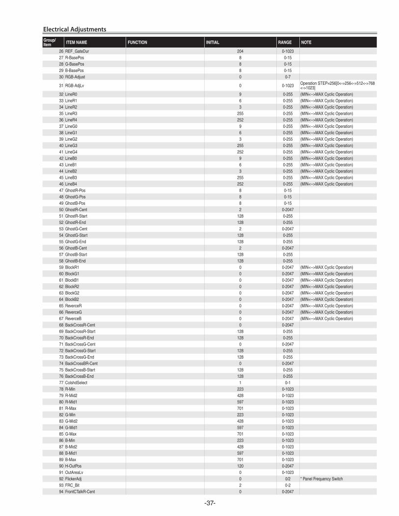
-37-
Electrical Adjustments
Group/Item ITEM NAME FUNCTION INITIAL RANGE NOTE
26 REF_GateDur 204 0-102327 R-BasePos 8 0-1528 G-BasePos 8 0-1529 B-BasePos 8 0-1530 RGB-Adjust 0 0-7
31 RGB-AdjLv 0 0-1023 OperationSTEP=256[0<->256<->512<->768<->1023]
32 LineR0 9 0-255 (MIN<-->MAXCyclicOperation)33 LineR1 6 0-255 (MIN<-->MAXCyclicOperation)34 LineR2 3 0-255 (MIN<-->MAXCyclicOperation)35 LineR3 255 0-255 (MIN<-->MAXCyclicOperation)36 LineR4 252 0-255 (MIN<-->MAXCyclicOperation)37 LineG0 9 0-255 (MIN<-->MAXCyclicOperation)38 LineG1 6 0-255 (MIN<-->MAXCyclicOperation)39 LineG2 3 0-255 (MIN<-->MAXCyclicOperation)40 LineG3 255 0-255 (MIN<-->MAXCyclicOperation)41 LineG4 252 0-255 (MIN<-->MAXCyclicOperation)42 LineB0 9 0-255 (MIN<-->MAXCyclicOperation)43 LineB1 6 0-255 (MIN<-->MAXCyclicOperation)44 LineB2 3 0-255 (MIN<-->MAXCyclicOperation)45 LineB3 255 0-255 (MIN<-->MAXCyclicOperation)46 LineB4 252 0-255 (MIN<-->MAXCyclicOperation)47 GhostR-Pos 8 0-1548 GhostG-Pos 8 0-1549 GhostB-Pos 8 0-1550 GhostR-Cent 2 0-204751 GhostR-Start 128 0-25552 GhostR-End 128 0-25553 GhostG-Cent 2 0-204754 GhostG-Start 128 0-25555 GhostG-End 128 0-25556 GhostB-Cent 2 0-204757 GhostB-Start 128 0-25558 GhostB-End 128 0-25559 BlockR1 0 0-2047 (MIN<-->MAXCyclicOperation)60 BlockG1 0 0-2047 (MIN<-->MAXCyclicOperation)61 BlockB1 0 0-2047 (MIN<-->MAXCyclicOperation)62 BlockR2 0 0-2047 (MIN<-->MAXCyclicOperation)63 BlockG2 0 0-2047 (MIN<-->MAXCyclicOperation)64 BlockB2 0 0-2047 (MIN<-->MAXCyclicOperation)65 ReverceR 0 0-2047 (MIN<-->MAXCyclicOperation)66 ReverceG 0 0-2047 (MIN<-->MAXCyclicOperation)67 ReverceB 0 0-2047 (MIN<-->MAXCyclicOperation)68 BackCrossR-Cent 0 0-204769 BackCrossR-Start 128 0-25570 BackCrossR-End 128 0-25571 BackCrossG-Cent 0 0-204772 BackCrossG-Start 128 0-25573 BackCrossG-End 128 0-25574 BackCrossBR-Cent 0 0-204775 BackCrossB-Start 128 0-25576 BackCrossB-End 128 0-25577 ColshdSelect 1 0-178 R-Min 223 0-102379 R-Mid2 428 0-102380 R-Mid1 597 0-102381 R-Max 701 0-102382 G-Min 223 0-102383 G-Mid2 428 0-102384 G-Mid1 597 0-102385 G-Max 701 0-102386 B-Min 223 0-102387 B-Mid2 428 0-102388 B-Mid1 597 0-102389 B-Max 701 0-102390 H-OutPos 120 0-204791 OutAreaLv 0 0-102392 FlickerAdj 0 0/2 *PanelFrequencySwitch93 FRC_Bit 2 0-294 FrontCTalkR-Cent 0 0-2047
-38-
Group/Item ITEM NAME FUNCTION INITIAL RANGE NOTE
95 FrontCTalkR-Start 128 0-25596 FrontCTalkR-End 128 0-25597 FrontCTalkG-Cent 0 0-204798 FrontCTalkG-Start 128 0-25599 FrontCTalkG-End 128 0-255
100 FrontCTalkB-Cent 0 0-2047101 FrontCTalkB-Start 128 0-255102 FrontCTalkB-End 128 0-255103 R-DCOffset-NGain 0/0 0-255 ScanDirection(Front/Rear)104 R-DCOffset-N1 511/511 0-511105 R-DCOffset-N2 0/0 0-511106 R-DCOffset-N3 0/0 0-511107 R-DCOffset-N4 0/0 0-511108 R-DCOffset-N5 0/0 0-511109 R-DCOffset-N6 0/0 0-511110 R-DCOffset-N7 0/0 0-511111 R-DCOffset-N8 0/0 0-511112 R-DCOffset-N9 0/0 0-511113 R-DCOffset-N10 0/0 0-511114 R-DCOffset-N11 0/0 0-511115 R-DCOffset-N12 491/491 0-511116 G-DCOffset-NGain 0/0 0-255117 G-DCOffset-N1 511/511 0-511118 G-DCOffset-N2 0/0 0-511119 G-DCOffset-N3 0/0 0-511120 G-DCOffset-N4 0/0 0-511121 G-DCOffset-N5 0/0 0-511122 G-DCOffset-N6 0/0 0-511123 G-DCOffset-N7 0/0 0-511124 G-DCOffset-N8 0/0 0-511125 G-DCOffset-N9 0/0 0-511126 G-DCOffset-N10 0/0 0-511127 G-DCOffset-N11 0/0 0-511128 G-DCOffset-N12 491/491 0-511129 B-DCOffset-NGain 0/0 0-255130 B-DCOffset-N1 511/511 0-511131 B-DCOffset-N2 0/0 0-511132 B-DCOffset-N3 0/0 0-511133 B-DCOffset-N4 0/0 0-511134 B-DCOffset-N5 0/0 0-511135 B-DCOffset-N6 0/0 0-511136 B-DCOffset-N7 0/0 0-511137 B-DCOffset-N8 0/0 0-511138 B-DCOffset-N9 0/0 0-511139 B-DCOffset-N10 0/0 0-511140 B-DCOffset-N11 0/0 0-511141 B-DCOffset-N12 491/491 0-511142 R-DCOffset-PGain 0/0 0-255143 R-DCOffset-P1 0/0 0-511144 R-DCOffset-P2 0/0 0-511145 R-DCOffset-P3 0/0 0-511146 R-DCOffset-P4 0/0 0-511147 R-DCOffset-P5 0/0 0-511148 R-DCOffset-P6 0/0 0-511149 R-DCOffset-P7 0/0 0-511150 R-DCOffset-P8 0/0 0-511151 R-DCOffset-P9 0/0 0-511152 R-DCOffset-P10 0/0 0-511153 R-DCOffset-P11 0/0 0-511154 R-DCOffset-P12 0/0 0-511155 G-DCOffset-PGain 0/0 0-255156 G-DCOffset-P1 4/4 0-511157 G-DCOffset-P2 0/0 0-511158 G-DCOffset-P3 0/0 0-511159 G-DCOffset-P4 0/0 0-511160 G-DCOffset-P5 0/0 0-511161 G-DCOffset-P6 0/0 0-511162 G-DCOffset-P7 0/0 0-511163 G-DCOffset-P8 0/0 0-511
Electrical Adjustments
-39-
Group/Item ITEM NAME FUNCTION INITIAL RANGE NOTE
164 G-DCOffset-P9 0/0 0-511165 G-DCOffset-P10 0/0 0-511166 G-DCOffset-P11 0/0 0-511167 G-DCOffset-P12 22/22 0-511168 B-DCOffset-PGain 0/0 0-255169 B-DCOffset-P1 4/4 0-511170 B-DCOffset-P2 0/0 0-511171 B-DCOffset-P3 0/0 0-511172 B-DCOffset-P4 0/0 0-511173 B-DCOffset-P5 0/0 0-511174 B-DCOffset-P6 0/0 0-511175 B-DCOffset-P7 0/0 0-511176 B-DCOffset-P8 0/0 0-511177 B-DCOffset-P9 0/0 0-511178 B-DCOffset-P10 0/0 0-511
179 B-DCOffset-P11 0/0 0-511
180 B-DCOffset-P12 22/22 0-511 ScanDirection(Front/Rear)
181 ENBX-R 0 0-127
182 ENBX-G 0 0-127183 ENBX-B 0 0-127 184 DXOutPos 0 0-1
PLC-XU78Group101 : Panel Service(6150/1060)
0 R-LCCOM 255 0-511 *CommonCenterAdjustment1 G-LCCOM 255 0-511 *CommonCenterAdjustment2 B-LCCOM 255 0-511 *CommonCenterAdjustment3 R-LCCOM-Gain 191 0-2554 G-LCCOM-Gain 191 0-2555 B-LCCOM-Gain 191 0-2556 R-LCCOM-Bright 0 0-2557 G-LCCOM-Bright 0 0-2558 B-LCCOM-Bright 0 0-2559 R-LCCOM-Cent 18 0-63
10 G-LCCOM-Cent 18 0-6311 B-LCCOM-Cent 18 0-6312 R-ENBX-PW 12 0-12713 G-ENBX-PW 12 0-12714 B-ENBX-PW 12 0-12715 R-DXIN 9 0-255 LinkwithNo.1816 G-DXIN 9 0-255 LinkwithNo.1917 B-DXIN 9 0-255 LinkwithNo.2018 R-CLXIN 9 0-255 LinkwithNo.1519 G-CLXIN 9 0-255 LinkwithNo.1620 B-CLXIN 9 0-255 LinkwithNo.1721 R-ENBX1IN 27 0-255 22 G-ENBX1IN 27 0-255 23 B-ENBX1IN 27 0-255
PLC-XU75
Group101 : Panel Service(6150/1060)0 R-LCCOM 280 0-511 *CommonCenterAdjustment1 G-LCCOM 280 0-511 *CommonCenterAdjustment2 B-LCCOM 280 0-511 *CommonCenterAdjustment3 R-LCCOM-Gain 191 0-2554 G-LCCOM-Gain 191 0-2555 B-LCCOM-Gain 191 0-2556 R-LCCOM-Bright 0 0-2557 G-LCCOM-Bright 0 0-2558 B-LCCOM-Bright 0 0-2559 R-LCCOM-Cent 18 0-63
10 G-LCCOM-Cent 18 0-6311 B-LCCOM-Cent 18 0-6312 R-ENBX-PW 11 0-12713 G-ENBX-PW 11 0-12714 B-ENBX-PW 11 0-12715 R-DXIN 5 0-255 LinkwithNo.1816 G-DXIN 5 0-255 LinkwithNo.1917 B-DXIN 5 0-255 LinkwithNo.20
Electrical Adjustments
-40-
Group/Item ITEM NAME FUNCTION INITIAL RANGE NOTE
18 R-CLXIN 5 0-255 LinkwithNo.1519 G-CLXIN 5 0-255 LinkwithNo.1620 B-CLXIN 5 0-255 LinkwithNo.1721 R-ENBX1IN 24 0-255 22 G-ENBX1IN 24 0-255 23 B-ENBX1IN 24 0-255
Group 200 Option
0 LogoProhibition(ForcedNoBrand) LogoProhibition(0:Menu,1:Forced,2:China,3-9:notused) 0 0-2 EffectiveafterACOn
1 RS232CBaudrate BaudRate 0 0-2 0:19200bps,1:9600bps,2:115200bps2 PJLinkEnable PJLink 0:Disable1:Enable3 ShippingSetting 0 0-20 Defaultsetwhenthevalueissetto104 CABLESW LongCable 0 0-10 0:Disable,1:Enable
5 PWDebugCommandEnable 0 0-1 0:Disable(SerialCommandEanble)1:Enable(PWDebugMode)
6 DeviceRefreshDisable 0 0-1 0:Enable,1:DisableNolastmemory
7 DeviceAccessDisable 0 0-1 0:Enable(Normal),1:DisableNolastmemory
20 ProjectorTimeReset 0 0-20 ProjectorTimeisclearedwhenthevalueissetto10
21 LampWarningTime(NORMAL) LampLifeatNormalMode(WarningTimeatNormal) 500-8000
22 LampWarningTime(ECO) LampLifeatEcoMode(WarningTimeatEco) 500-8000
23 LampWarningTime(HIGH) LampLifeatHighMode(WarningTimeatHigh) 500-8000
30 Lamplifetestenable 0:Disable1:Enable,forsafetytestonly31 LmapOntime(forlifetest) Fortestpurpose32 LampOfftime(forlifetest) Fortestpurpose33 Lamptotaltime(forlifetest) Fortestpurpose40 LampPWMPresAv50Hz LampPWMPRES0Setting(AV50Hz) 80 0-25541 LampPWMPresAv60Hz LampPWMPRES0Setting(AV60Hz) 67 0-25542 LampPWMPresUnlock LampPWMPRES0Setting(NoSignal) 67 0-25543 LampPWMPresPcA LampPWMFrequencySettingA 2 0-25544 LampPWMPresPcB LampPWMFrequencySettingB 3 0-25545 LampPWMPrefHAv50Hz LampPWMPREF0Setting(AV50Hz) 5000 0-6553546 LampPWMPrefHAv60Hz LampPWMPREF0Setting(AV60Hz) 5000 0-6553547 LampPWMPrefHUnlock LampPWMPREF0Setting(NoSignal) 5000 0-6553550 LampReplacementDisplay LampWarningDisplayOn/Off 1 0-1 1:On,0:Off51 FilterWarningDisplay FilterWarningDisplayOn/Off 1 0-1 1:On,0:Off52 LampCounterresetTimes ResetTimesofLampCounter 0 0-255 Readonly54 FactoryDefaultExecuteTimes ResettimesofFanctoryDefault 0 0-255 Readonly55 MotorDisable MotorsDisable 0 0-1 0:On,1:Off56 MenuPosition Movemenu(Xasis) 0 0-102457 MenuPosition Movemenu(Yasis) 0 0-102459 SourceSearchEnable SourceSearchEnable(0:Disable1:Enable) 0 0-1
Group 201 Option (signal)
0 FrameLockOption 1 0-10:FrameLockOFFatPCsignal1:FrameLockONatPCsignaland47Hz(Vfreq)~Panelfrequencyofinputsignal
2 FieldSenseInvertEnable 0 0-1
ReverseProcessingofFLDINVSettingValue0:Disable-UsedFLDINVSettingValue1:Enable-UsedReversedFLDINVSettingValue
3
4 SubImageEnable 1 0-10:Disable(ServiceAdjustmentDsiable,UsedalltheCenterValues1:Enable(ServiceAdjustmentEnable)
6 ZoomAcceleratorEnable 0 0-10:ZoomAcceleratorOFF,1:ZoomAcceleratorONNolastmemory
7 DZoomResetbyKeystone 0 0-10:Enable(Normal),1:Disable(DzooisnotcancelledevenifKeystoneiscancelled)Nolastmemory
8 StabilityCount CountValueofV-missing 5 0-255
9 SensivityforSignalLost(HSYNC) OnlyusedthisvalueforNoSignalJudgement(Hz) 350 0-32767
10 SensivityforSignalLost(VSYNC) OnlyusedthisvalueforNoSignalJudgement(Line) 3 0-255
11 KeystoneFilterCenterValue ReferenceValue 16 0-30Group 205 Spread Spectrum
0 SpreadSpectrumEnable 1 0-1 0:Off,1:On
Electrical Adjustments
-41-
Group/Item ITEM NAME FUNCTION INITIAL RANGE NOTE
1 SpreadSpectrumFrequency 80 0-500
2 SpreadSpectrumAmplitude PLC-XU78:50PLC-XU75:100 0-300
PLC-XU78Group 210 LampContorl
0 DIMMER_CTRL_LEVEL1 LuminanceLevel1DataforDimmer:DimLevel1atthelessthantheValue 7 0-255
1 DIMMER_CTRL_LEVEL2 LuminanceLevel2DataforDimmer:DimLevel2atthelessthantheValue 14 0-255
2 DIMMER_CTRL_LEVEL3 LuminanceLevel3DataforDimmer:DimLevel3atthelessthantheValue 21 0-255
3 DIMMER_CTRL_LEVEL4 LuminanceLevel4DataforDimmer:DimLevel4atthelessthantheValue 28 0-255
4 DIMMER_CTRL_LEVEL5 LuminanceLevel5DataforDimmer:DimLevel5atthelessthantheValue 35 0-255
5 DIMMER_CTRL_LEVEL6 LuminanceLevel6DataforDimmer:DimLevel6atthelessthantheValue 42 0-255
6 DIMMER_CTRL_LEVEL7 LuminanceLevel7DataforDimmer:DimLevel7atthelessthantheValue 49 0-255
7 DIMMER_CTRL_LEVEL8 LuminanceLevel8DataforDimmer:DimLevel8atthelessthantheValue 56 0-255
8 DIMMER_CTRL_LEVEL9 LuminanceLevel9DataforDimmer:DimLevel9atthelessthantheValue 63 0-255
9 DIMMER_CTRL_LEVEL10 LuminanceLevel10DataforDimmer:DimLevel10atthelessthantheValue 70 0-255
10 DIMMER_CTRL_LEVEL11 LuminanceLevel11DataforDimmer:DimLevel11atthelessthantheValue 77 0-255
11 DIMMER_CTRL_LEVEL12 LuminanceLevel12DataforDimmer:DimLevel12atthelessthantheValue 84 0-255
12 DIMMER_CTRL_LEVEL13 LuminanceLevel13DataforDimmer:DimLevel13atthelessthantheValue 91 0-255
13 DIMMER_CTRL_LEVEL14 LuminanceLevel14DataforDimmer:DimLevel14atthelessthantheValue 98 0-255
14 DIMMER_CTRL_LEVEL15 LuminanceLevel15DataforDimmer:DimLevel15atthelessthantheValue 105 0-255
15 DIMMER_AVERAGE_POINT LuminanceDataAvaragePointforMimmer 4 0-1616 DIMMER_AVERAGE_DATA LuminanceDataAvarageValueforDimmer - - *Readonly17 DIMMER_LEVEL_AUTO CurrentDimmerLeverl - - *Readonly18 DIMMER_LEVEL_NORMAL NormalDimmerLevel 15 0-1519 DIMMER_LEVEL_ECO EcoDimmerLevel 0 0-1520 Panellifemode Panellifemode 0 0-121 VOLTAGE_LEVEL LampVoltage - Unit:8bit(RawData)*Readonly
PLC-XU75Group 210 LampContorl
0 DIMMER_CTRL_LEVEL1 LuminanceLevel1DataforDimmer:DimLevel1atthelessthantheValue 9 0-255
1 DIMMER_CTRL_LEVEL2 LuminanceLevel2DataforDimmer:DimLevel2atthelessthantheValue 18 0-255
2 DIMMER_CTRL_LEVEL3 LuminanceLevel3DataforDimmer:DimLevel3atthelessthantheValue 26 0-255
3 DIMMER_CTRL_LEVEL4 LuminanceLevel4DataforDimmer:DimLevel4atthelessthantheValue 35 0-255
4 DIMMER_CTRL_LEVEL5 LuminanceLevel5DataforDimmer:DimLevel5atthelessthantheValue 44 0-255
5 DIMMER_CTRL_LEVEL6 LuminanceLevel6DataforDimmer:DimLevel6atthelessthantheValue 53 0-255
6 DIMMER_CTRL_LEVEL7 LuminanceLevel7DataforDimmer:DimLevel7atthelessthantheValue 61 0-255
7 DIMMER_CTRL_LEVEL8 LuminanceLevel8DataforDimmer:DimLevel8atthelessthantheValue 70 0-255
8 DIMMER_CTRL_LEVEL9 LuminanceLevel9DataforDimmer:DimLevel9atthelessthantheValue 79 0-255
9 DIMMER_CTRL_LEVEL10 LuminanceLevel10DataforDimmer:DimLevel10atthelessthantheValue 88 0-255
10 DIMMER_CTRL_LEVEL11 LuminanceLevel11DataforDimmer:DimLevel11atthelessthantheValue 96 0-255
11 DIMMER_CTRL_LEVEL12 LuminanceLevel12DataforDimmer:DimLevel12atthelessthantheValue 105 0-255
12 DIMMER_CTRL_LEVEL13 LuminanceLevel13DataforDimmer:DimLevel13atthelessthantheValue 255 0-255
13 DIMMER_CTRL_LEVEL14 LuminanceLevel14DataforDimmer:DimLevel14atthelessthantheValue 255 0-255
14 DIMMER_CTRL_LEVEL15 LuminanceLevel15DataforDimmer:DimLevel15atthelessthantheValue 255 0-255
15 DIMMER_AVERAGE_POINT LuminanceDataAvaragePointforMimmer 4 0-1616 DIMMER_AVERAGE_DATA LuminanceDataAvarageValueforDimmer - - *Readonly
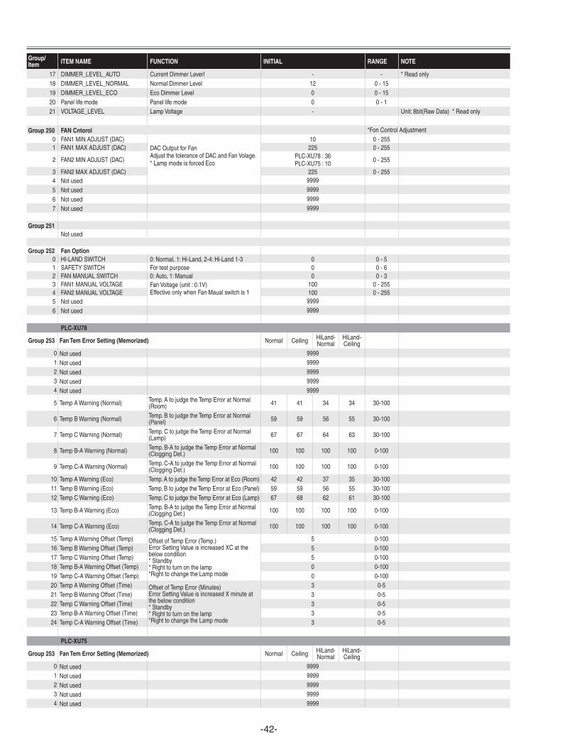
-4�-
Group/Item ITEM NAME FUNCTION INITIAL RANGE NOTE
17 DIMMER_LEVEL_AUTO CurrentDimmerLeverl - - *Readonly18 DIMMER_LEVEL_NORMAL NormalDimmerLevel 12 0-1519 DIMMER_LEVEL_ECO EcoDimmerLevel 0 0-1520 Panellifemode Panellifemode 0 0-121 VOLTAGE_LEVEL LampVoltage - Unit:8bit(RawData)*Readonly
Group 250 FAN Cntorol *FonControlAdjustment0 FAN1MINADJUST(DAC)
DACOutputforFanAdjustthetoleranceofDACandFanVolage.*LampmodeisforcedEco
10 0-2551 FAN1MAXADJUST(DAC) 225 0-255
2 FAN2MINADJUST(DAC) PLC-XU78:36PLC-XU75:10 0-255
3 FAN2MAXADJUST(DAC) 225 0-2554 Notused 9999
5 Notused 9999
6 Notused 9999
7 Notused 9999
Group 251Notused
Group 252 Fan Option0 HI-LANDSWITCH 0:Normal,1:Hi-Land,2-4:Hi-Land1-3 0 0-51 SAFETYSWITCH Fortestpurpose 0 0-62 FANMANUALSWITCH 0:Auto,1:Manual 0 0-33 FAN1MANUALVOLTAGE FanVoltage(unit:0.1V)
EffectiveonlywhenFanMaualswitchis1100 0-255
4 FAN2MANUALVOLTAGE 100 0-2555 Notused 9999
6 Notused 9999
PLC-XU78
Group 253 Fan Tem Error Setting (Memorized) Normal Ceiling HiLand-Normal
HiLand-Ceiling
0 Notused 99991 Notused 99992 Notused 99993 Notused 99994 Notused 9999
5 TempAWarning(Normal) Temp.AtojudgetheTempErroratNormal(Room) 41 41 34 34 30-100
6 TempBWarning(Normal) Temp.BtojudgetheTempErroratNormal(Panel) 59 59 56 55 30-100
7 TempCWarning(Normal) Temp.CtojudgetheTempErroratNormal(Lamp) 67 67 64 63 30-100
8 TempB-AWarning(Normal) Temp.B-AtojudgetheTempErroratNormal(CloggingDet.) 100 100 100 100 0-100
9 TempC-AWarning(Normal) Temp.C-AtojudgetheTempErroratNormal(CloggingDet.) 100 100 100 100 0-100
10 TempAWarning(Eco) Temp.AtojudgetheTempErroratEco(Room) 42 42 37 35 30-10011 TempBWarning(Eco) Temp.BtojudgetheTempErroratEco(Panel) 59 59 56 55 30-10012 TempCWarning(Eco) Temp.CtojudgetheTempErroratEco(Lamp) 67 68 62 61 30-100
13 TempB-AWarning(Eco) Temp.B-AtojudgetheTempErroratNormal(CloggingDet.) 100 100 100 100 0-100
14 TempC-AWarning(Eco) Temp.C-AtojudgetheTempErroratNormal(CloggingDet.) 100 100 100 100 0-100
15 TempAWarningOffset(Temp) OffsetofTempError(Temp.)ErrorSettingValueisincreasedXCatthebelowcondition*Standby*Righttoturnonthelamp*RighttochangetheLampmode
5 0-10016 TempBWarningOffset(Temp) 5 0-10017 TempCWarningOffset(Temp) 5 0-10018 TempB-AWarningOffset(Temp) 0 0-10019 TempC-AWarningOffset(Temp) 0 0-10020 TempAWarningOffset(Time) OffsetofTempError(Minutes)
ErrorSettingValueisincreasedXminuteatthebelowcondition*Standby*Righttoturnonthelamp*RighttochangetheLampmode
3 0-521 TempBWarningOffset(Time) 3 0-522 TempCWarningOffset(Time) 3 0-523 TempB-AWarningOffset(Time) 3 0-524 TempC-AWarningOffset(Time) 3 0-5
PLC-XU75
Group 253 Fan Tem Error Setting (Memorized) Normal Ceiling HiLand-Normal
HiLand-Ceiling
0 Notused 99991 Notused 99992 Notused 99993 Notused 99994 Notused 9999
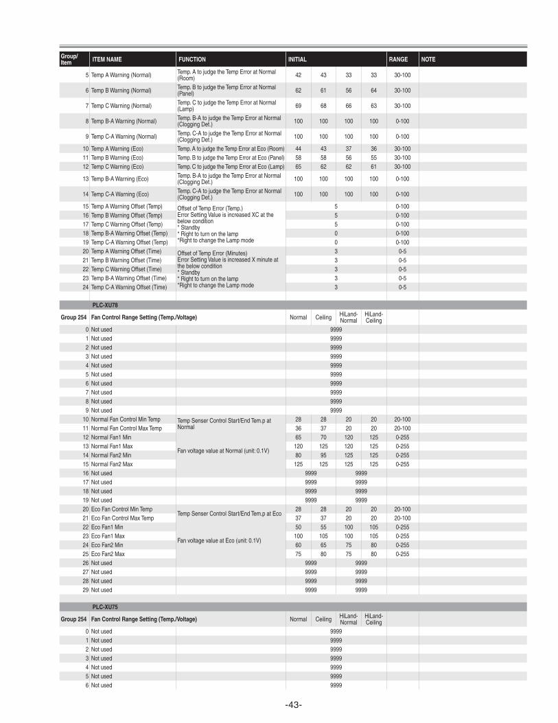
-43-
Group/Item ITEM NAME FUNCTION INITIAL RANGE NOTE
5 TempAWarning(Normal) Temp.AtojudgetheTempErroratNormal(Room) 42 43 33 33 30-100
6 TempBWarning(Normal) Temp.BtojudgetheTempErroratNormal(Panel) 62 61 56 64 30-100
7 TempCWarning(Normal) Temp.CtojudgetheTempErroratNormal(Lamp) 69 68 66 63 30-100
8 TempB-AWarning(Normal) Temp.B-AtojudgetheTempErroratNormal(CloggingDet.) 100 100 100 100 0-100
9 TempC-AWarning(Normal) Temp.C-AtojudgetheTempErroratNormal(CloggingDet.) 100 100 100 100 0-100
10 TempAWarning(Eco) Temp.AtojudgetheTempErroratEco(Room) 44 43 37 36 30-10011 TempBWarning(Eco) Temp.BtojudgetheTempErroratEco(Panel) 58 58 56 55 30-10012 TempCWarning(Eco) Temp.CtojudgetheTempErroratEco(Lamp) 65 62 62 61 30-100
13 TempB-AWarning(Eco) Temp.B-AtojudgetheTempErroratNormal(CloggingDet.) 100 100 100 100 0-100
14 TempC-AWarning(Eco) Temp.C-AtojudgetheTempErroratNormal(CloggingDet.) 100 100 100 100 0-100
15 TempAWarningOffset(Temp) OffsetofTempError(Temp.)ErrorSettingValueisincreasedXCatthebelowcondition*Standby*Righttoturnonthelamp*RighttochangetheLampmode
5 0-10016 TempBWarningOffset(Temp) 5 0-10017 TempCWarningOffset(Temp) 5 0-10018 TempB-AWarningOffset(Temp) 0 0-10019 TempC-AWarningOffset(Temp) 0 0-10020 TempAWarningOffset(Time) OffsetofTempError(Minutes)
ErrorSettingValueisincreasedXminuteatthebelowcondition*Standby*Righttoturnonthelamp*RighttochangetheLampmode
3 0-521 TempBWarningOffset(Time) 3 0-522 TempCWarningOffset(Time) 3 0-523 TempB-AWarningOffset(Time) 3 0-524 TempC-AWarningOffset(Time) 3 0-5
PLC-XU78
Group 254 Fan Control Range Setting (Temp./Voltage) Normal Ceiling HiLand-Normal
HiLand-Ceiling
0 Notused 99991 Notused 99992 Notused 99993 Notused 99994 Notused 99995 Notused 99996 Notused 99997 Notused 99998 Notused 99999 Notused 9999
10 NormalFanControlMinTemp TempSenserControlStart/EndTem.patNormal
28 28 20 20 20-10011 NormalFanControlMaxTemp 36 37 20 20 20-10012 NormalFan1Min
FanvoltagevalueatNormal(unit:0.1V)
65 70 120 125 0-25513 NormalFan1Max 120 125 120 125 0-25514 NormalFan2Min 80 95 125 125 0-25515 NormalFan2Max 125 125 125 125 0-25516 Notused 9999 999917 Notused 9999 999918 Notused 9999 999919 Notused 9999 999920 EcoFanControlMinTemp
TempSenserControlStart/EndTem.patEco28 28 20 20 20-100
21 EcoFanControlMaxTemp 37 37 20 20 20-10022 EcoFan1Min
FanvoltagevalueatEco(unit:0.1V)
50 55 100 105 0-25523 EcoFan1Max 100 105 100 105 0-25524 EcoFan2Min 60 65 75 80 0-25525 EcoFan2Max 75 80 75 80 0-25526 Notused 9999 999927 Notused 9999 999928 Notused 9999 999929 Notused 9999 9999
PLC-XU75
Group 254 Fan Control Range Setting (Temp./Voltage) Normal Ceiling HiLand-Normal
HiLand-Ceiling
0 Notused 99991 Notused 99992 Notused 99993 Notused 99994 Notused 99995 Notused 99996 Notused 9999
-44-
Group/Item ITEM NAME FUNCTION INITIAL RANGE NOTE
7 Notused 99998 Notused 99999 Notused 9999
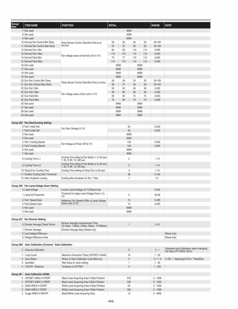
10 NormalFanControlMinTemp TempSenserControlStart/EndTem.patNormal
29 30 20 20 20-10011 NormalFanControlMaxTemp 37 37 20 20 20-10012 NormalFan1Min
FanvoltagevalueatNormal(unit:0.1V)
60 60 110 110 0-25513 NormalFan1Max 110 110 110 110 0-25514 NormalFan2Min 75 77 110 110 0-25515 NormalFan2Max 110 110 110 110 0-25516 Notused 9999 999917 Notused 9999 999918 Notused 9999 999919 Notused 9999 999920 EcoFanControlMinTemp
TempSenserControlStart/EndTem.patEco29 29 20 20 20-100
21 EcoFanControlMaxTemp 38 37 20 20 20-10022 EcoFan1Min
FanvoltagevalueatEco(unit:0.1V)
50 50 90 90 0-25523 EcoFan1Max 90 90 90 90 0-25524 EcoFan2Min 60 65 75 75 0-25525 EcoFan2Max 75 80 75 75 0-25526 Notused 9999 999927 Notused 9999 999928 Notused 9999 999929 Notused 9999 9999
Group 255 Fan Start/Cooling Setting0 Fan1InitialVolt
FanStartVoltage(0.1V)55 0-255
1 Fan2InitialVolt 55 0-2552 Notused 99993 Notused 99994 Fan1CoolingSpeed
FanVoltageatPowerOff(0.1V)130 0-255
5 Fan2CoolingSpeed 130 0-2556 Notused 99997 Notused 9999
8 CoolingTimeL1 CoolingTimesttingatFanModeL1(x30sec)1:30,3:90,15:450sec. 2 1-15
9 CoolingTimeL2 CoolingTimesttingatFanModeL2(x30sec)1:30,3:90,15:450sec. 3 1-15
10 TempErrorCoolingTime CoolingTimesettingatTempErro(x30sec) 3 1-1511 OnStartCoolingStartThreshold 38 0-10012 Aftershutdowncooling Coolingaftershutdown(0:No,1:Yes) 1 0-1
Group 256 Fan Lamp Voltage Down Setting0 LampVoltage CurrentLampVoltage(0.1V)(Readonly) - 0-255
1 LampVolThreshold ThresholdtojudgeLampVoltageDown(V×10) 0 30-90
2 Fan1SpeedGain AdditionalFanSpeedofMinatLampVoltageDown(unit:0.1V)
10 0-2553 Fan2SpeedGain 10 0-2554 Notused 99995 Notused 9999
Group 257 Fan Dimmer Setting
0 DimmerAverageCheckPeriod DimmerAvaragemeasurementTime(0:10sec,1:30sec,2:6sec,90sec...10:300sec) 1 0-10
1 DimmerAverage DimmerAvarageValue(Readonly)2 LastVoltageDifference (Readonly)3 VoltageDifferenceGoal (Readonly)
Group 260 Auto Calibration (Commn) * Auto Calibration
0 ExecuteCalibration 0 0-1 ExecutesAuto-CalibrationwhenchangiingtheValue(PCWhite100%)
1 LoopCount MaximumExecutionTimes(OFFSET->GAIN) 10 1-302 AutoStatus ResultofAuto-Calibration(LastMemory) 0 0/1/9 0:OK,1:Adjusting,9:Error*ReadOnly3 AutoWait WaitValueforeachsetting 1 1-204 CHECK-Tolelance TorelanceofOFFSET 2 1-255
Group 261 Auto Calibration (RGB)0 OFFSETAREAHSTART BlackLevelAcquiringAreaH-StartPosition 975 0-10001 OFFSETAREAVSTART BlackLevelAcquiringAreaV-StartPosition 500 0-10002 GAINAREAHSTART WhiteLevelAcquiringAreaH-StartPosition 25 0-10003 GAINAREAVSTART WhiteLevelAcquiringAreaV-StartPosition 500 0-10004 ImageAREAHWIDTH Black/WhiteLevelAcquiringArea 13 0-4095
-45-
Group/Item ITEM NAME FUNCTION INITIAL RANGE NOTE
5 ImageAREAVHIGHT Black/WhiteLevelAcquiringAreaHeight 9 0-40956 OFFSETtarget TargetValueofBlackLevelAdj. 3 0-1277 OFFSETtorelance TorelanceofBlackLevelAdj. 1 1-1278 GAINtarget TargetValueofWhiteLevelAdj. 238 0-2559 GAINtorelance TorelanceofWhiteLevelAdj. 1 1-255
Group 262 Auto Calibration (CVBS/SVIDEO)0 YImageAreaStartX YAcquiringAreaH-StartPosition 20 0-10001 YImageAreaStartY YAcquiringAreaV-StartPosition 500 0-10006 ImageAreaHWidth ImageLevelAcquiringArea 13 0-40957 ImageAreaVHight ImageLevelAcquiringAreaHeight 20 0-40958 YTargetLevel TargetValueofYLevelAdj. 217 0-255
11 GainTolerance TorelanceofLevelAdj. 1 0-25512 DeltaGain DeviationWidthofGainValue 9 0-255
Group 264 Auto Calibration (YCbCr)0 Y-OFFSETAREAHSTART Y-OffsetAcquiringAreaH-StartPosition 925 0-10001 Y-OFFSETAREAVSTART Y-OffsetAcquiringAreaV-StartPosition 500 0-10002 CB-OFFSETAREAHSTART CB-OffsetAcquiringAreaH-StartPosition 925 0-1000 Ifnotused:useY'svalue3 CB-OFFSETAREAVSTART CB-OffsetAcquiringAreaV-StartPosition 500 0-1000 Ifnotused:useY'svalue4 CR-OFFSETAREAHSTART CR-OffsetAcquiringAreaH-StartPosition 925 0-1000 Ifnotused:useY'svalue5 CR-OFFSETAREAVSTART CR-OffsetAcquiringAreaV-StartPosition 500 0-1000 Ifnotused:useY'svalue6 Y-GAINAREAHSTART Y 50 0-10007 Y-GAINAREAVSTART 500 0-10008 CB-GAINAREAHSTART 800 0-10009 CB-GAINAREAVSTART 500 0-1000
10 CR-GAINAREAHSTART 700 0-100011 CR-GAINAREAVSTART 500 0-100012 ImageAREAHWIDTH YCBCRLevelAcquiringArea 8 0-409513 ImageAREAVHIGHT YCBCRLevelAcquiringAreaHeight 9 0-409514 Y-OFFSETTARTGET 4 0-25515 CBOFFSETTARGET 128 0-25516 CROFFSETTARGET 128 0-25517 Y-GAINTARGET 217 0-25518 CB-GAINTARGET 237 0-25519 CR-GAINTARGET 237 0-25520 OFFSETtorelance TorelanceofOFFSETAdj. 1 1-25521 GAINtorelance TorelanceofGAINAdj. 1 1-255
Group 270 Custom (Aspect)0 ScalerHorizontal H-Scaler 100 68-1321 ScalerVertical V-Scaler 100 68-1322 Connect LinkEdit1:Link 0 0-13 PositionHorizontal H-Position 100 85-1154 PositionVertical V-Position 100 85-1155 AspectEnable AspectEnable(0:On,1:Off) 0 0-1
Group 280 AutoPC Adjsut
0 AutoPCAdjustEnable Auto-PCAdjOperationEnableifUn-supportedSignalInput 0 0-1 0:Enable,1:Disable
1 FrequencyStep FrequencyStepsofTotalDot 1 0-32 FrequencyThreshold TotalDotFreqencyThreshold 5 0-10 0[]<-------->10[Notmatched]3 FinePhase DoPhaseAdjafterTotalDotAdj. 1 0-1 0:ExecutesFinePhase,1:NotExecute4 BLKDET BlackLevelDetectionArea 1 0-3
5 PHASEMSK PhaseDetectionFilter 0 0-30:EffectiveAllBit,1:DisableLower1bit2:DisableLower2bit,3:DisableLower3bit
Group 290 PanelType * Panel Type Check
0 GammaL/R-View CurrentSettingCheck 0 0-20 0:GammaforL-Turn20:GammaforR-Turn*Readonly
1 GammaL/R-Change SettingofGamma 10 0-20 SetsL-TurnGammaiftheValueissetto0.SetsR-TurnGammaiftheValueissetto20.
Group 500 Composite (NTSC) Composite / S-Video0 *Readonly1 DispDots 668 0~40952 HBackPorch 28 0~40953 VBackPorch 18 0~40954 DispLine 458 0~4095
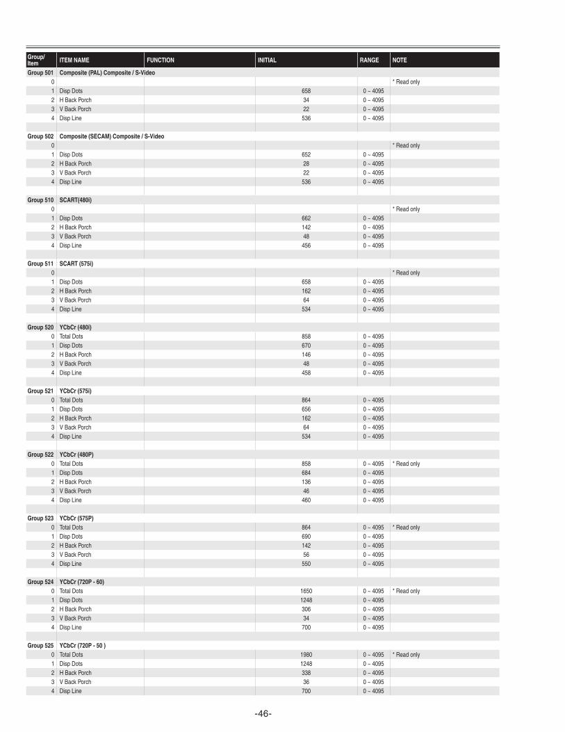
-46-
Group/Item ITEM NAME FUNCTION INITIAL RANGE NOTE
Group 501 Composite (PAL) Composite / S-Video0 *Readonly1 DispDots 658 0~40952 HBackPorch 34 0~40953 VBackPorch 22 0~40954 DispLine 536 0~4095
Group 502 Composite (SECAM) Composite / S-Video0 *Readonly1 DispDots 652 0~40952 HBackPorch 28 0~40953 VBackPorch 22 0~40954 DispLine 536 0~4095
Group 510 SCART(480i)0 *Readonly1 DispDots 662 0~40952 HBackPorch 142 0~40953 VBackPorch 48 0~40954 DispLine 456 0~4095
Group 511 SCART (575i)0 *Readonly1 DispDots 658 0~40952 HBackPorch 162 0~40953 VBackPorch 64 0~40954 DispLine 534 0~4095
Group 520 YCbCr (480i)0 TotalDots 858 0~40951 DispDots 670 0~40952 HBackPorch 146 0~40953 VBackPorch 48 0~40954 DispLine 458 0~4095
Group 521 YCbCr (575i)0 TotalDots 864 0~40951 DispDots 656 0~40952 HBackPorch 162 0~40953 VBackPorch 64 0~40954 DispLine 534 0~4095
Group 522 YCbCr (480P)0 TotalDots 858 0~4095 *Readonly1 DispDots 684 0~40952 HBackPorch 136 0~40953 VBackPorch 46 0~40954 DispLine 460 0~4095
Group 523 YCbCr (575P)0 TotalDots 864 0~4095 *Readonly1 DispDots 690 0~40952 HBackPorch 142 0~40953 VBackPorch 56 0~40954 DispLine 550 0~4095
Group 524 YCbCr (720P - 60)0 TotalDots 1650 0~4095 *Readonly1 DispDots 1248 0~40952 HBackPorch 306 0~40953 VBackPorch 34 0~40954 DispLine 700 0~4095
Group 525 YCbCr (720P - 50 )0 TotalDots 1980 0~4095 *Readonly1 DispDots 1248 0~40952 HBackPorch 338 0~40953 VBackPorch 36 0~40954 DispLine 700 0~4095
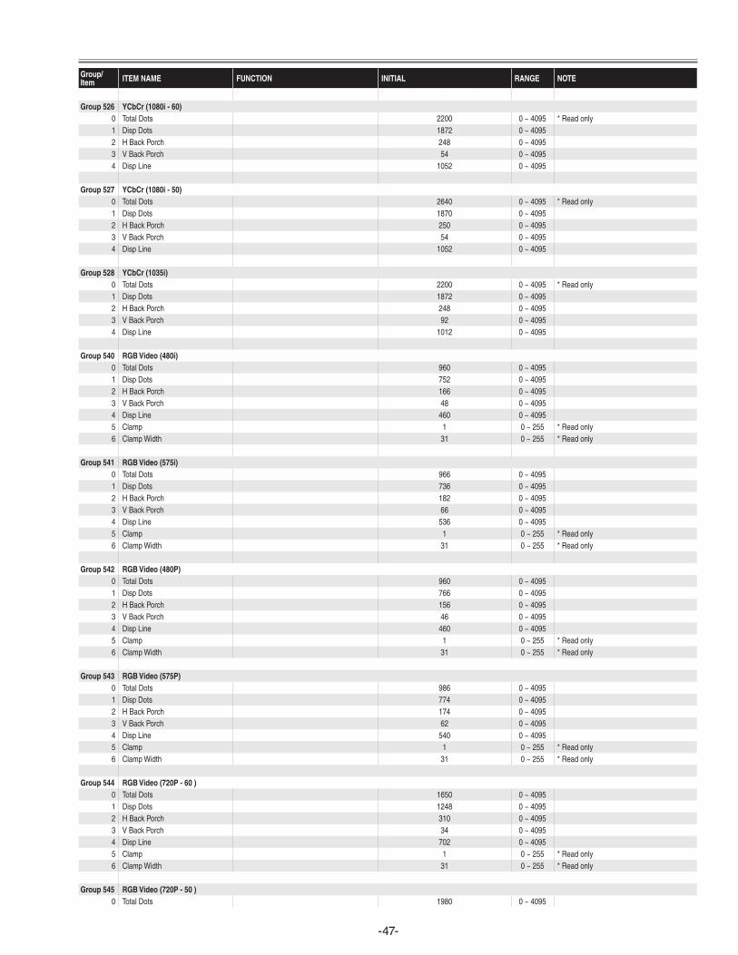
-47-
Group/Item ITEM NAME FUNCTION INITIAL RANGE NOTE
Group 526 YCbCr (1080i - 60)0 TotalDots 2200 0~4095 *Readonly1 DispDots 1872 0~40952 HBackPorch 248 0~40953 VBackPorch 54 0~40954 DispLine 1052 0~4095
Group 527 YCbCr (1080i - 50)0 TotalDots 2640 0~4095 *Readonly1 DispDots 1870 0~40952 HBackPorch 250 0~40953 VBackPorch 54 0~40954 DispLine 1052 0~4095
Group 528 YCbCr (1035i)0 TotalDots 2200 0~4095 *Readonly1 DispDots 1872 0~40952 HBackPorch 248 0~40953 VBackPorch 92 0~40954 DispLine 1012 0~4095
Group 540 RGB Video (480i)0 TotalDots 960 0~40951 DispDots 752 0~40952 HBackPorch 166 0~40953 VBackPorch 48 0~40954 DispLine 460 0~40955 Clamp 1 0~255 *Readonly6 ClampWidth 31 0~255 *Readonly
Group 541 RGB Video (575i)0 TotalDots 966 0~40951 DispDots 736 0~40952 HBackPorch 182 0~40953 VBackPorch 66 0~40954 DispLine 536 0~40955 Clamp 1 0~255 *Readonly6 ClampWidth 31 0~255 *Readonly
Group 542 RGB Video (480P)0 TotalDots 960 0~40951 DispDots 766 0~40952 HBackPorch 156 0~40953 VBackPorch 46 0~40954 DispLine 460 0~40955 Clamp 1 0~255 *Readonly6 ClampWidth 31 0~255 *Readonly
Group 543 RGB Video (575P)0 TotalDots 986 0~40951 DispDots 774 0~40952 HBackPorch 174 0~40953 VBackPorch 62 0~40954 DispLine 540 0~40955 Clamp 1 0~255 *Readonly6 ClampWidth 31 0~255 *Readonly
Group 544 RGB Video (720P - 60 )0 TotalDots 1650 0~40951 DispDots 1248 0~40952 HBackPorch 310 0~40953 VBackPorch 34 0~40954 DispLine 702 0~40955 Clamp 1 0~255 *Readonly6 ClampWidth 31 0~255 *Readonly
Group 545 RGB Video (720P - 50 )0 TotalDots 1980 0~4095
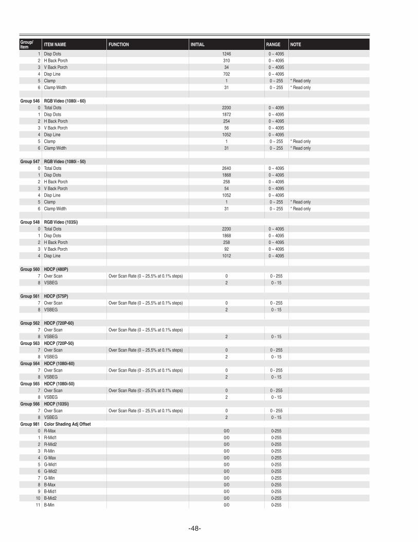
-48-
Group/Item ITEM NAME FUNCTION INITIAL RANGE NOTE
1 DispDots 1246 0~40952 HBackPorch 310 0~40953 VBackPorch 34 0~40954 DispLine 702 0~40955 Clamp 1 0~255 *Readonly6 ClampWidth 31 0~255 *Readonly
Group 546 RGB Video (1080i - 60)0 TotalDots 2200 0~40951 DispDots 1872 0~40952 HBackPorch 254 0~40953 VBackPorch 56 0~40954 DispLine 1052 0~40955 Clamp 1 0~255 *Readonly6 ClampWidth 31 0~255 *Readonly
Group 547 RGB Video (1080i - 50)0 TotalDots 2640 0~40951 DispDots 1868 0~40952 HBackPorch 258 0~40953 VBackPorch 54 0~40954 DispLine 1052 0~40955 Clamp 1 0~255 *Readonly6 ClampWidth 31 0~255 *Readonly
Group 548 RGB Video (1035i)0 TotalDots 2200 0~40951 DispDots 1868 0~40952 HBackPorch 258 0~40953 VBackPorch 92 0~40954 DispLine 1012 0~4095
Group 560 HDCP (480P)7 OverScan OverScanRate(0~25.5%at0.1%steps) 0 0-2558 VSBEG 2 0-15
Group 561 HDCP (575P)7 OverScan OverScanRate(0~25.5%at0.1%steps) 0 0-2558 VSBEG 2 0-15
Group 562 HDCP (720P-60)7 OverScan OverScanRate(0~25.5%at0.1%steps)8 VSBEG 2 0-15
Group 563 HDCP (720P-50)7 OverScan OverScanRate(0~25.5%at0.1%steps) 0 0-2558 VSBEG 2 0-15
Group 564 HDCP (1080i-60)7 OverScan OverScanRate(0~25.5%at0.1%steps) 0 0-2558 VSBEG 2 0-15
Group 565 HDCP (1080i-50)7 OverScan OverScanRate(0~25.5%at0.1%steps) 0 0-2558 VSBEG 2 0-15
Group 566 HDCP (1035i)7 OverScan OverScanRate(0~25.5%at0.1%steps) 0 0-2558 VSBEG 2 0-15
Group 981 Color Shading Adj Offset0 R-Max 0/0 0-2551 R-Mid1 0/0 0-2552 R-Mid2 0/0 0-2553 R-Min 0/0 0-2554 G-Max 0/0 0-2555 G-Mid1 0/0 0-2556 G-Mid2 0/0 0-2557 G-Min 0/0 0-2558 B-Max 0/0 0-2559 B-Mid1 0/0 0-255
10 B-Mid2 0/0 0-25511 B-Min 0/0 0-255
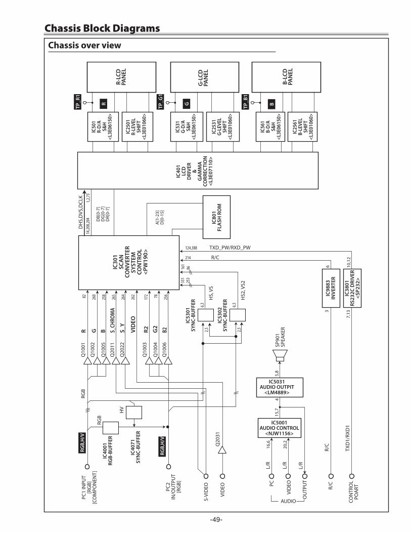
-49-
IC30
1SC
AN
CON
VERT
ERSY
STEM
CO
NTR
OL
<PW
190>
IC50
1R-
D/A
S&H
<L3E
0615
0>
R-LC
DPA
NEL
G-L
CDPA
NEL
B-LC
DPA
NEL
PC1
INPU
T[R
GB]
[CO
MPO
NEN
T]
PC2
IN/O
UTP
UT
[RG
B] PC
IC5001AUDIO CONTROL
<NJW1156>
IC5031 AUDIO OUTPIT
<LM4889>
OU
TPU
T
CON
TRO
L PO
ART
R/C
IC80
1FL
ASH
RO
M
VID
EO
AUDIO
DH
S,D
VS,D
CLK
DB[
0-7]
D
G[0
-7]
DR[
0-7]
A[1
-23]
D[0
-15]
14,20
8,204
1,2,73
331
253
161
86
6,3
15,7
5,8
6 10,1
2 214
124,388 TXD_PW/RXD_PW
TXD
1/RX
D1
R/C
R/C
16,6
20,2
4
82
260
258
265
264
262
2,5
3
7,13
SP90
1 SP
EAKE
R
L/R
VID
EO
S-VI
DEO
L/R
L/R
RGB,
H/V
RGB,
H/V
TP_R
1
R G B
HS,
VS
HS2
, VS2
IC25
01R-
LEVE
LSH
IFT
<L3E
0106
0>
IC53
1G-
D/A
S&H
<L3E
0615
0>
IC25
31G-
LEVE
LSH
IFT
<L3E
0106
0>
IC56
1B-
D/A
S&H
<L3E
0615
0>
IC25
61B-
LEVE
LSH
IFT
<L3E
0106
0>
IC38
01
RS23
2C D
RIVE
R <S
P232
>
IC98
83IN
VERT
ER
TP_G
1
TP_B
1
Q10
01
Q20
31
R G
B S_CH
ROM
A
S_Y
VID
EO
Q10
02
Q10
05
Q20
11
172 78 256
R2 G2
B2
Q10
03
Q10
04
Q10
06
Q20
22
IC40
01
RGB-
BUFF
ER
IC40
71SY
NC-
BUFF
ER
IC53
01SY
NC-
BUFF
ER 6,32,5
IC53
02SY
NC-
BUFF
ER
RGB
HV
RGB
IC40
1LC
DD
RIVE
R&
GA
MM
ACO
RREC
TIO
N<L
3E07
110>
Chassis over view
Chassis Block Diagrams
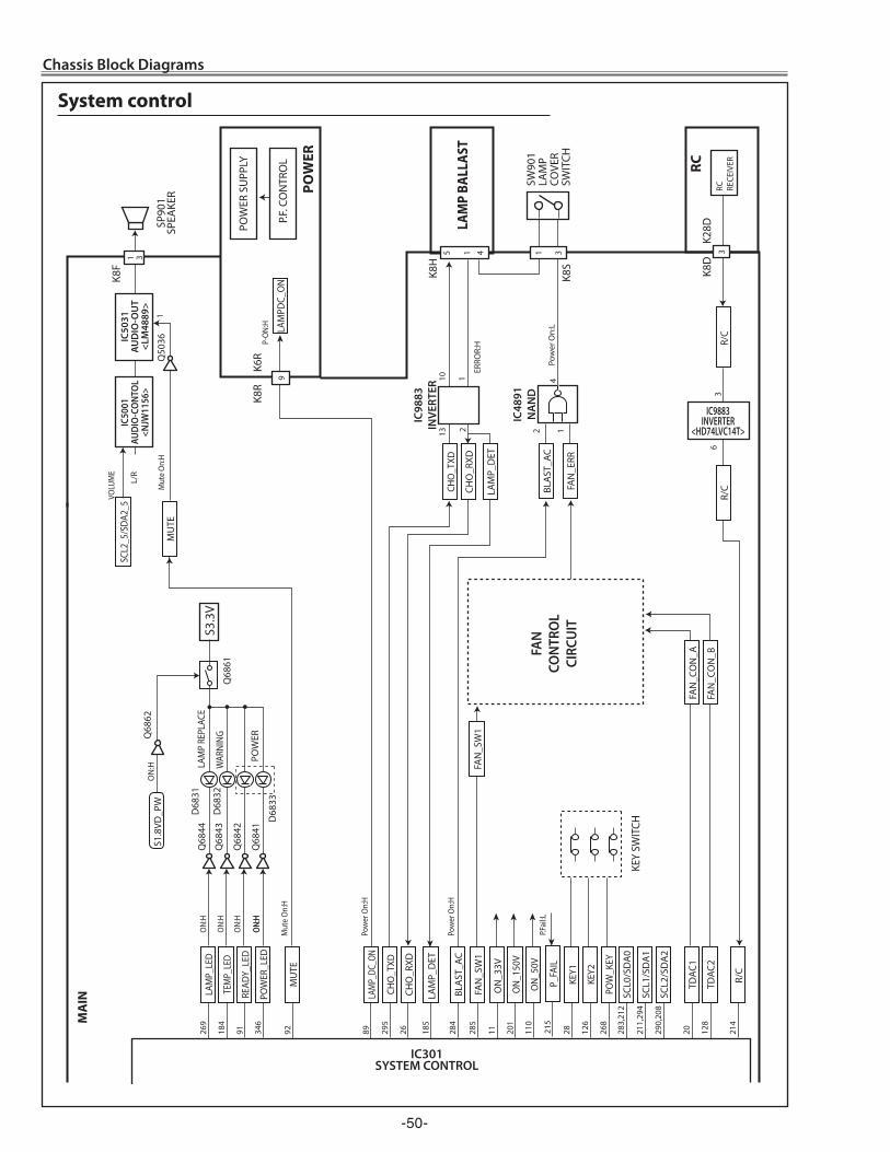
-50-
POW
ER
LAM
P BA
LLAS
T
IC50
31
AUD
IO-O
UT
<LM
4889
>
IC50
01AU
DIO
-CO
NTO
L<N
JW11
56>
RC
RECE
IVER
POW
ER S
UPP
LY
SW90
1 LA
MP
COVE
R SW
ITCH
P.F. C
ON
TRO
L
SP90
1 SP
EAKE
R M
UTE
LAM
PDC_
ON
RC
MA
IN
Q68
42
FAN
_CO
N_A
FAN
_CO
N_B
R/
C
IC9883INVERTER
<HD74LVC14T>
3
4
ON:
H
ON:
H
ON:
H
ON:
H
ERRO
R:H
P-O
N:H
P.Fai
l:L
ON:
H
6
2 1
1 M
ute
On:
H
Mut
e O
n:H
Pow
er O
n:H
Pow
er O
n:H
Pow
er O
n:L
L/R
VOLU
ME
POW
ER_L
ED
BLA
ST_A
C
BLA
ST_A
C
FAN
_ERR
TEM
P_LE
D
ON
_33V
ON
_150
V
346
284
184
11
LAM
P_D
ET
185
201
LAM
P_LE
D
ON
_50V
269
110
P_FA
IL
FAN
_SW
1FA
N_S
W1
LAM
P_DC
_ON
READ
Y_LE
D
215
285
8991
CHO
_TXD
CHO
_RXD
CHO
_TXD
CHO
_RXD
MU
TE
KEY1
295
26
92 28
KEY2
126
POW
_KEY
R/C
R/C
SCL1
/SD
A1
SCL2
/SD
A2
268
214
211,
294
SCL0
/SD
A0
283,
212
290,
208
TDAC
1
TDAC
2
20 128
IC301 SYSTEM CONTROL
Q68
43
Q68
44
D68
31
D68
32
D68
33
Q50
36
Q68
41
LAM
P RE
PLAC
E
WAR
NING
POW
ER
IC48
91
NA
ND
2 13
1 10
IC98
83IN
VERT
ER
K8R
K6R
K8S
3 1
K8H
4 5 1
K8D
K2
8D
3
S3.3
VQ
6861
FAN
CON
TRO
LCI
RCU
IT
KEY
SWIT
CH
SCL2
_5/S
DA2_
5
9
K8F
1 3
S1.8
VD_P
W
ON
:H
Q68
62
LAM
P_D
ET
System control
Chassis Block Diagrams
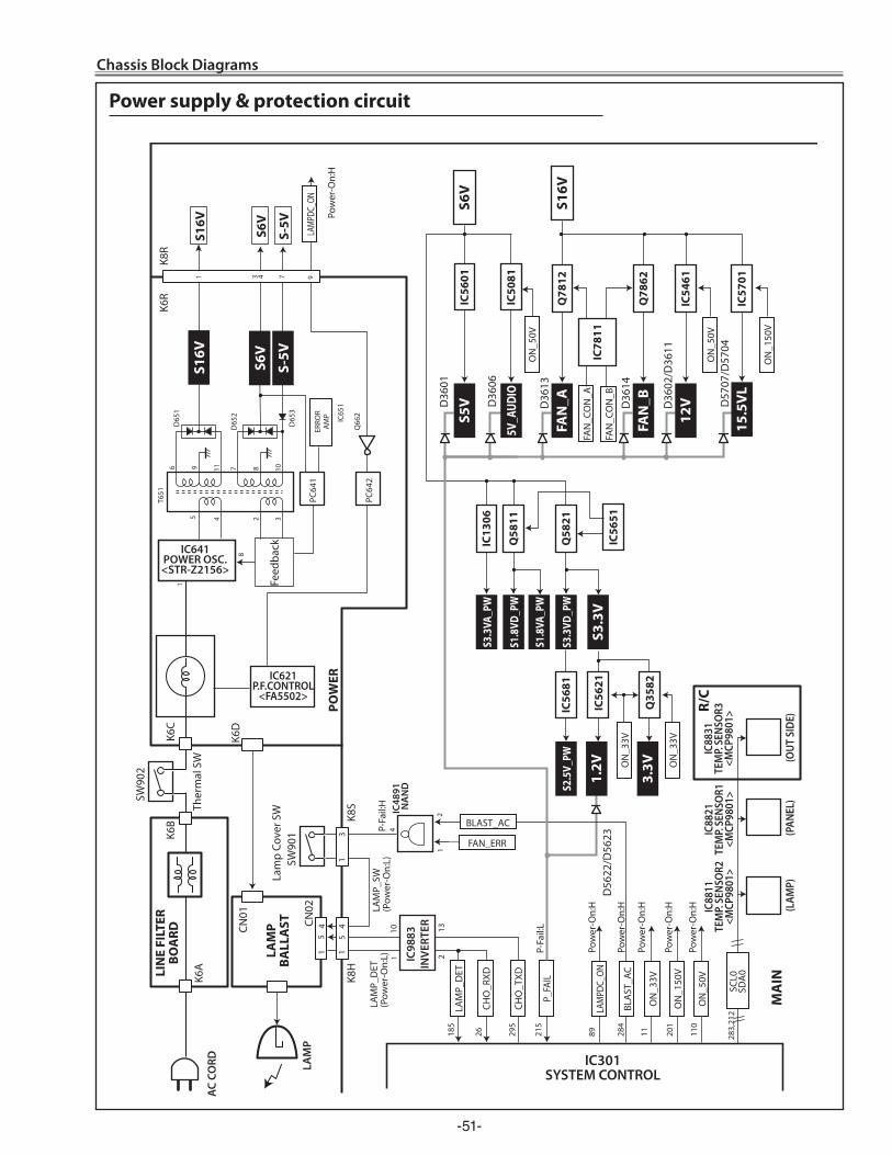
-51-
IC301 SYSTEM CONTROL
CHO
_RXD
CHO
_TXD
P_FA
IL
ON
_33V
FAN_ERR
ON
_150
V
BLA
ST_A
C
BLAST_AC
S5V
1.2V
S6V
IC56
01
D36
01
D56
22/D
5623
D36
06
S3.3
V
LIN
E FI
LTER
BO
ARD
LAM
P BA
LLA
ST
1 4
5 5 4
1 CN
02
K8H
1
3 K8
S
K6D
CN01
K6C
K6B
LAM
P
AC
CORD
K6R
K8R
POW
ER
R/C
MA
IN
IC621P.F.CONTROL
<FA5502>
6
5
1
8
4 32
9 11 7 8 10
2
10
1
1
4
T651
D65
2
D65
1
D65
3
IC65
1
Q66
2
PC64
1ER
ROR
AM
PPo
wer
-On:
H
Pow
er-O
n:H
Pow
er-O
n:H
Pow
er-O
n:H
Pow
er-O
n:H
Pow
er-O
n:H
P-Fa
il:H
LA
MP_
DET
(P
ower
-On:
L)
LAM
P_SW
(P
ower
-On:
L)
P-Fa
il:L
PC64
2
IC641POWER OSC.<STR-Z2156>
Feed
back
S6V
S16V
S-5V ON
_150
V
LAM
PDC_
ON
IC48
91
NA
ND
S6V
S16V
S-5V
1 3 4 7
IC88
11TE
MP.
SENS
OR2
<MCP
9801
>
(LAM
P)(P
ANEL
)(O
UT S
IDE)
IC88
21TE
MP.
SENS
OR1
<MCP
9801
>
IC88
31TE
MP.
SENS
OR3
<MCP
9801
>
26
LAM
P_D
ET
185
2 13
295
215
11
201
ON
_50V
11
0
LAM
PDC_
ON89 28
4
283,
212
SCL0
SDA
0
IC98
83IN
VERT
ER
SW90
1
S16V
FAN
_AQ
7812
D36
13
D57
07/D
5704
9
IC56
21
S3.3
VA_P
WIC
1306
S1.8
VA_P
W
S3.3
VD_P
WQ
5821
S2.5
V_PW
IC56
81
IC56
51
S1.8
VD_P
WQ
5811
5V_A
UDIO
IC50
81
15.5
VL
ON
_50V
FAN
_CO
N_A
FAN
_BQ
7862
IC78
11
IC57
01
D36
14
12V
IC54
61D
3602
/D36
11
FAN
_CO
N_B
ON
_33V
3.3V
Q35
82
ON
_33V
ON
_50V
K6A
SW90
2
Ther
mal
SW
Lam
p Co
ver S
W
Power supply & protection circuit
Chassis Block Diagrams
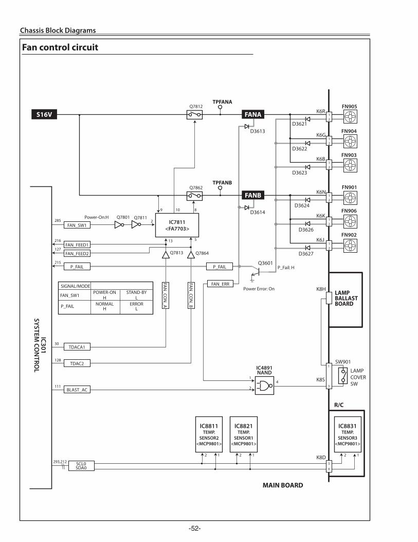
-5�-
Chassis Block Diagrams
FAN_FEED1216
FAN_FEED2127
Q3601
D3621
D3622
SW901
LAMPCOVERSW
R/C
LAMP BALLAST BOARD
K6R
K6G
FN905
FN904
1 2
1 2
D3624
K6N
K6K
FN901
FN906
1 2
D3623
K6BFN903
12
1 2
1
2 1 2 1
S16V FANA
FANB
Q7812 TPFANA
Q7813
Q7801
5 13
2
8 10 9
IC7811 <FA7703>
Q7862
Q7864
Q7811
P_FAIL
FAN_SW1
D3613
D3614
D3626
K6JFN902
12
D3627
IC8821TEMP.
SENSOR1<MCP9801>
2 1
IC8811TEMP.
SENSOR2<MCP9801>
IC8831TEMP.
SENSOR3<MCP9801>
MAIN BOARD
IC301 SYSTEM
CON
TROL
FAN
_CON
_B
FAN
_CON
_A
Power-On:H
IC4891 NAND
1
2 4
215
285
293,212 SCL0SDA0
Power Error: On
P_Fail: H
SIGNAL/MODE POWER-ON STAND-BY H L NORMAL ERROR H L
FAN_SW1
P_FAIL
P_FAIL
FAN_ERR
TPFANB
K8S
K8H
111
K8D
3
5
6
1
1
BLAST_AC
30TDACA1
128TDAC2
Fan control circuit
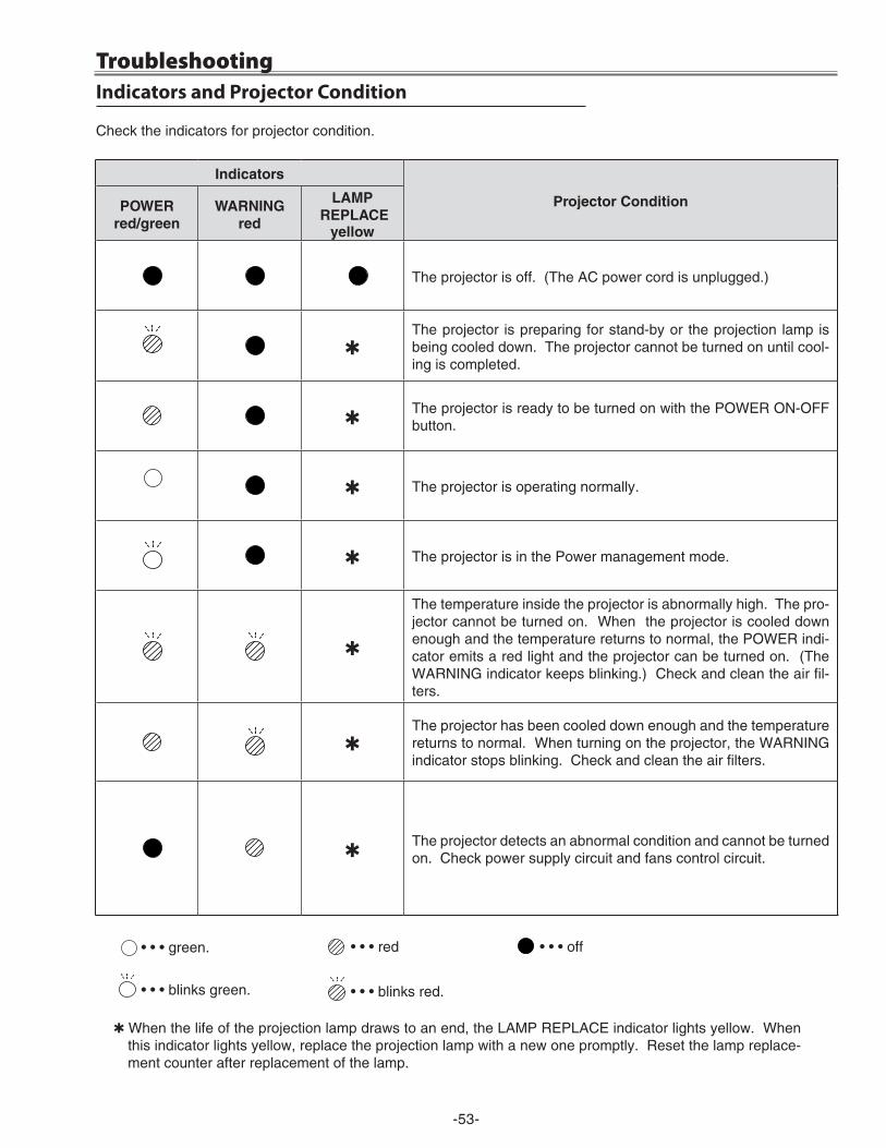
-53-
Check the indicators for projector condition.
• • • green. • • • red • • • off
• • • blinks green.
Q When the life of the projection lamp draws to an end, the LAMP REPLACE indicator lights yellow. When this indicator lights yellow, replace the projection lamp with a new one promptly. Reset the lamp replace-ment counter after replacement of the lamp.
Indicators and Projector Condition
• • • blinks red.
Troubleshooting
Indicators
Projector conditionPoWerred/green
WArNINGred
LAMP rePLAce
yellow
The projector is off. (The AC power cord is unplugged.)
QThe projector is preparing for stand-by or the projection lamp is being cooled down. The projector cannot be turned on until cool-ing is completed.
QThe projector is ready to be turned on with the POWER ON-OFF button.
Q The projector is operating normally.
Q The projector is in the Power management mode.
Q
The temperature inside the projector is abnormally high. The pro-jector cannot be turned on. When the projector is cooled down enough and the temperature returns to normal, the POWER indi-cator emits a red light and the projector can be turned on. (The WARNING indicator keeps blinking.) Check and clean the air fil-ters.
QThe projector has been cooled down enough and the temperature returns to normal. When turning on the projector, the WARNING indicator stops blinking. Check and clean the air filters.
QThe projector detects an abnormal condition and cannot be turned on. Check power supply circuit and fans control circuit.
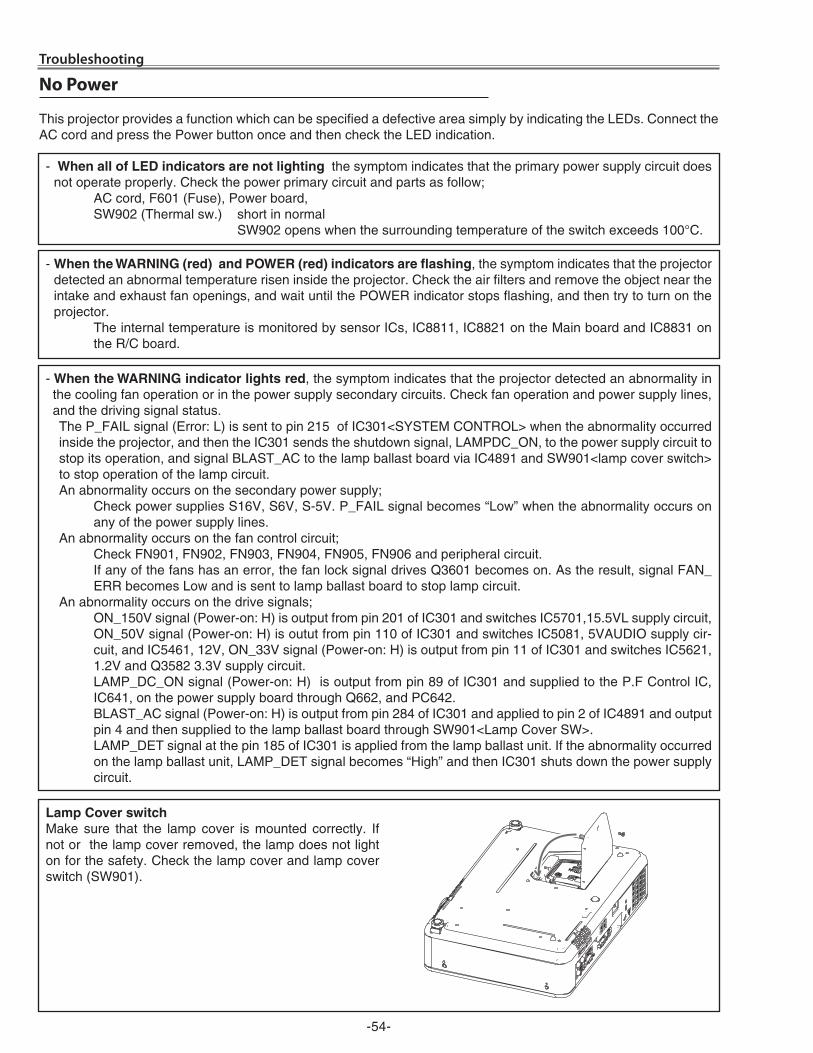
-54-
No Power
- When all of Led indicators are not lighting, the symptom indicates that the primary power supply circuit does not operate properly. Check the power primary circuit and parts as follow;
AC cord, F601 (Fuse), Power board, SW90� (Thermal sw.) short in normal SW90� opens when the surrounding temperature of the switch exceeds 100°C.
This projector provides a function which can be specified a defective area simply by indicating the LEDs. Connect the AC cord and press the Power button once and then check the LED indication.
- When the WArNING (red) and PoWer (red) indicators are flashing, the symptom indicates that the projector detected an abnormal temperature risen inside the projector. Check the air filters and remove the object near the intake and exhaust fan openings, and wait until the POWER indicator stops flashing, and then try to turn on the projector.
The internal temperature is monitored by sensor ICs, IC8811, IC88�1 on the Main board and IC8831 on the R/C board.
- When the WArNING indicator lights red, the symptom indicates that the projector detected an abnormality in the cooling fan operation or in the power supply secondary circuits. Check fan operation and power supply lines, and the driving signal status. The P_FAIL signal (Error: L) is sent to pin �15 of IC301<SYSTEM CONTROL> when the abnormality occurred inside the projector, and then the IC301 sends the shutdown signal, LAMPDC_ON, to the power supply circuit to stop its operation, and signal BLAST_AC to the lamp ballast board via IC4891 and SW901<lamp cover switch> to stop operation of the lamp circuit. An abnormality occurs on the secondary power supply; Check power supplies S16V, S6V, S-5V. P_FAIL signal becomes “Low” when the abnormality occurs on
any of the power supply lines.An abnormality occurs on the fan control circuit; Check FN901, FN90�, FN903, FN904, FN905, FN906 and peripheral circuit. If any of the fans has an error, the fan lock signal drives Q3601 becomes on. As the result, signal FAN_
ERR becomes Low and is sent to lamp ballast board to stop lamp circuit. An abnormality occurs on the drive signals; ON_150V signal (Power-on: H) is output from pin �01 of IC301 and switches IC5701,15.5VL supply circuit,
ON_50V signal (Power-on: H) is outut from pin 110 of IC301 and switches IC5081, 5VAUDIO supply cir-cuit, and IC5461, 1�V, ON_33V signal (Power-on: H) is output from pin 11 of IC301 and switches IC56�1, 1.�V and Q358� 3.3V supply circuit.
LAMP_DC_ON signal (Power-on: H) is output from pin 89 of IC301 and supplied to the P.F Control IC, IC641, on the power supply board through Q66�, and PC64�.
BLAST_AC signal (Power-on: H) is output from pin �84 of IC301 and applied to pin � of IC4891 and output pin 4 and then supplied to the lamp ballast board through SW901<Lamp Cover SW>.
LAMP_DET signal at the pin 185 of IC301 is applied from the lamp ballast unit. If the abnormality occurred on the lamp ballast unit, LAMP_DET signal becomes “High” and then IC301 shuts down the power supply circuit.
Troubleshooting
Lamp cover switchMake sure that the lamp cover is mounted correctly. If not or the lamp cover removed, the lamp does not light on for the safety. Check the lamp cover and lamp cover switch (SW901).
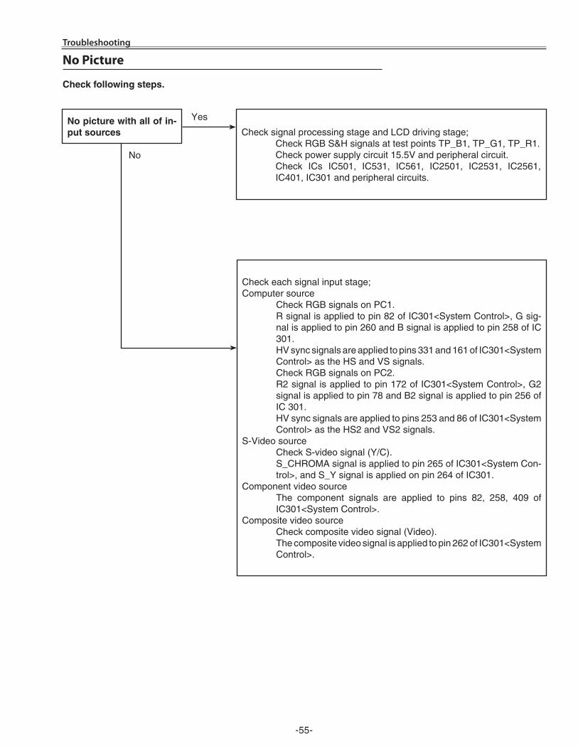
-55-
Troubleshooting
No Picture
No picture with all of in-put sources Check signal processing stage and LCD driving stage;
Check RGB S&H signals at test points TP_B1, TP_G1, TP_R1. Check power supply circuit 15.5V and peripheral circuit. Check ICs IC501, IC531, IC561, IC�501, IC�531, IC�561,
IC401, IC301 and peripheral circuits.
Yes
No
check following steps.
Check each signal input stage;Computer source Check RGB signals on PC1. R signal is applied to pin 8� of IC301<System Control>, G sig-
nal is applied to pin �60 and B signal is applied to pin �58 of IC 301.
HV sync signals are applied to pins 331 and 161 of IC301<System Control> as the HS and VS signals.
Check RGB signals on PC�. R� signal is applied to pin 17� of IC301<System Control>, G�
signal is applied to pin 78 and B� signal is applied to pin �56 of IC 301.
HV sync signals are applied to pins �53 and 86 of IC301<System Control> as the HS� and VS� signals.
S-Video source Check S-video signal (Y/C). S_CHROMA signal is applied to pin �65 of IC301<System Con-
trol>, and S_Y signal is applied on pin �64 of IC301.Component video source The component signals are applied to pins 8�, �58, 409 of
IC301<System Control>.Composite video source Check composite video signal (Video). The composite video signal is applied to pin �6� of IC301<System
Control>.
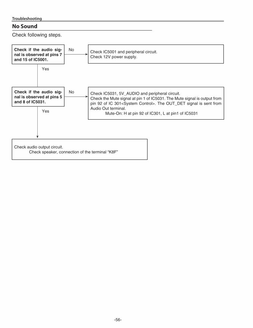
-56-
Troubleshooting
No Sound
Check IC5001 and peripheral circuit.Check 1�V power supply.
check if the audio sig-nal is observed at pins 7 and 15 of Ic5001.
Check audio output circuit. Check speaker, connection of the terminal “K8F”
Yes
No
Check following steps.
Check IC5031, 5V_AUDIO and peripheral circuit.Check the Mute signal at pin 1 of IC5031. The Mute signal is output from pin 9� of IC 301<System Control>. The OUT_DET signal is sent from Audio Out terminal. Mute-On: H at pin 9� of IC301, L at pin1 of IC5031
check if the audio sig-nal is observed at pins 5 and 8 of Ic5031.
Yes
No
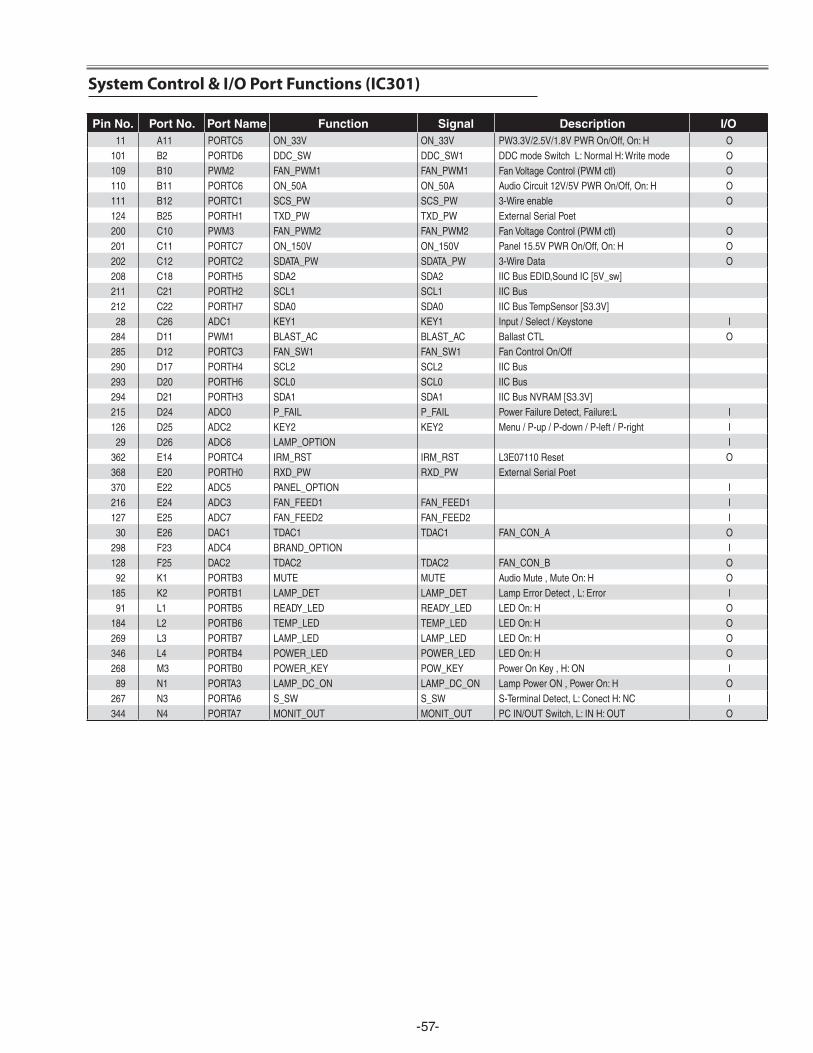
-57-
Pin No. Port No. Port Name Function Signal description I/o11 A11 PORTC5 ON_33V ON_33V PW3.3V/2.5V/1.8VPWROn/Off,On:H O
101 B2 PORTD6 DDC_SW DDC_SW1 DDCmodeSwitchL:NormalH:Writemode O109 B10 PWM2 FAN_PWM1 FAN_PWM1 FanVoltage Control(PWMctl) O110 B11 PORTC6 ON_50A ON_50A AudioCircuit12V/5VPWROn/Off,On:H O111 B12 PORTC1 SCS_PW SCS_PW 3-Wireenable O124 B25 PORTH1 TXD_PW TXD_PW ExternalSerialPoet200 C10 PWM3 FAN_PWM2 FAN_PWM2 FanVoltage Control(PWMctl) O201 C11 PORTC7 ON_150V ON_150V Panel15.5VPWROn/Off,On:H O202 C12 PORTC2 SDATA_PW SDATA_PW 3-WireData O208 C18 PORTH5 SDA2 SDA2 IICBusEDID,SoundIC[5V_sw]211 C21 PORTH2 SCL1 SCL1 IICBus212 C22 PORTH7 SDA0 SDA0 IICBusTempSensor[S3.3V]
28 C26 ADC1 KEY1 KEY1 Input/Select/Keystone I284 D11 PWM1 BLAST_AC BLAST_AC BallastCTL O285 D12 PORTC3 FAN_SW1 FAN_SW1 FanControlOn/Off290 D17 PORTH4 SCL2 SCL2 IICBus293 D20 PORTH6 SCL0 SCL0 IICBus294 D21 PORTH3 SDA1 SDA1 IICBusNVRAM[S3.3V]215 D24 ADC0 P_FAIL P_FAIL PowerFailureDetect,Failure:L I126 D25 ADC2 KEY2 KEY2 Menu/P-up/P-down/P-left/P-right I
29 D26 ADC6 LAMP_OPTION I362 E14 PORTC4 IRM_RST IRM_RST L3E07110Reset O368 E20 PORTH0 RXD_PW RXD_PW ExternalSerialPoet370 E22 ADC5 PANEL_OPTION I216 E24 ADC3 FAN_FEED1 FAN_FEED1 I127 E25 ADC7 FAN_FEED2 FAN_FEED2 I
30 E26 DAC1 TDAC1 TDAC1 FAN_CON_A O298 F23 ADC4 BRAND_OPTION I128 F25 DAC2 TDAC2 TDAC2 FAN_CON_B O
92 K1 PORTB3 MUTE MUTE AudioMute,MuteOn:H O185 K2 PORTB1 LAMP_DET LAMP_DET LampErrorDetect,L:Error I
91 L1 PORTB5 READY_LED READY_LED LEDOn:H O184 L2 PORTB6 TEMP_LED TEMP_LED LEDOn:H O269 L3 PORTB7 LAMP_LED LAMP_LED LEDOn:H O346 L4 PORTB4 POWER_LED POWER_LED LEDOn:H O268 M3 PORTB0 POWER_KEY POW_KEY PowerOnKey,H:ON I
89 N1 PORTA3 LAMP_DC_ON LAMP_DC_ON LampPowerON,PowerOn:H O267 N3 PORTA6 S_SW S_SW S-TerminalDetect,L:ConectH:NC I344 N4 PORTA7 MONIT_OUT MONIT_OUT PCIN/OUTSwitch,L:INH:OUT O
System Control & I/O Port Functions (IC301)
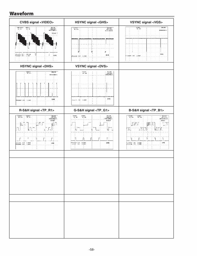
-58-
WaveformcVBS signal <VIdeo> HSYNc signal <GHS> VSYNc signal <VGS>
HSYNc signal <dHS> VSYNc signal <dVS>
r-S&H signal <tP_r1> G-S&H signal <tP_G1> B-S&H signal <tP_B1>
-59-
Cleaning
cleaning with air spray
1. Remove the cabinet top following to “Mechanical Dis-assemblies”.
�. Clean up the LCD panel and polarizing plate by using the air spray from the cabinet top opening.
caution:Use a commercial (inert gas) air spray designed for cleaning camera and computer equipment. Use a resin-based nozzle only. Be vary careful not to damage optical parts with the nozzle tip. Never use any kind of cleanser on the unit. Also, never use abrasive materials on the unit as this may cause irreparable damage.
After long periods of use, dust and other particles will accumulate on the LCD panel, prism, mirror, polarized glass, lens, etc., causing the picture to darken or color to blur. If this occurs, clean the inside of optical unit.
Remove dust and other particles using air spray. If dirt cannot be removed by air spray, disassemble and clean the optical unit.
disassembly cleaning
Disassembly cleaning method should only be performed when the unit is considerable dirty and cannot be suf-ficiently cleaned by air spraying alone. Be sure to readjust the optical system after perform-ing disassembly cleaning.
1. Remove the cabinet top and main units following to “Mechanical Disassemblies”.
�. Remove the optical base top following to “Optical Unit Disassemblies”. If the LCD panel needs cleaning, re-move the LCD panel unit following to “LCD panel re-placement”.
3. Clean the optical parts with a soft cloth. Clean ex-tremely dirty areas using a cloth moistened with al-cohol.
caution:The surface of the optical components consists of mul-tiple dielectric layers with varying degrees of refraction. Never use organic solvents (thinner, etc.) or any kind of cleanser on these components.Since the LCD panel is equipped with an electronic cir-cuit, never use any liquids (water, etc.) to clean the unit. Use of liquid may cause the unit to malfunction.
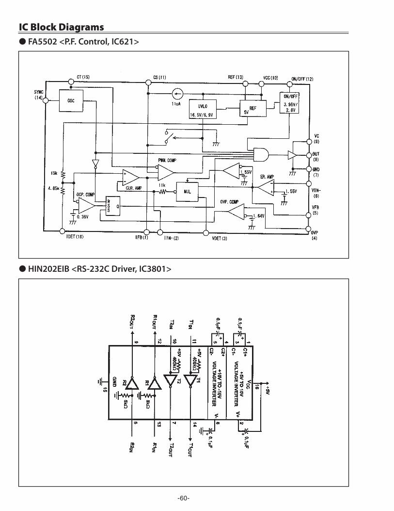
-60-
IC Block Diagrams● FA5502 <P.F. Control, IC621>
● HIN202EIB <RS-232C Driver, IC3801>
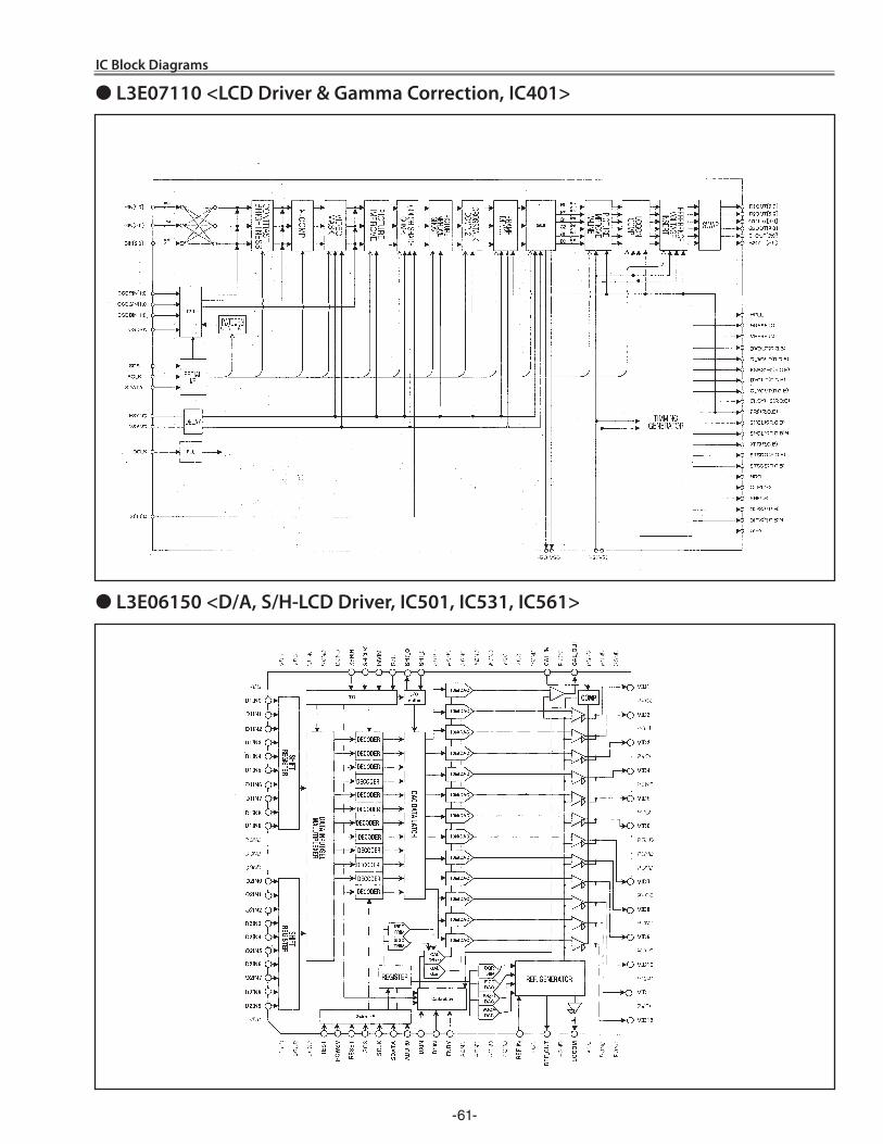
-61-
IC Block Diagrams
● L3E07110 <LCD Driver & Gamma Correction, IC401>
● L3E06150 <D/A, S/H-LCD Driver, IC501, IC531, IC561>
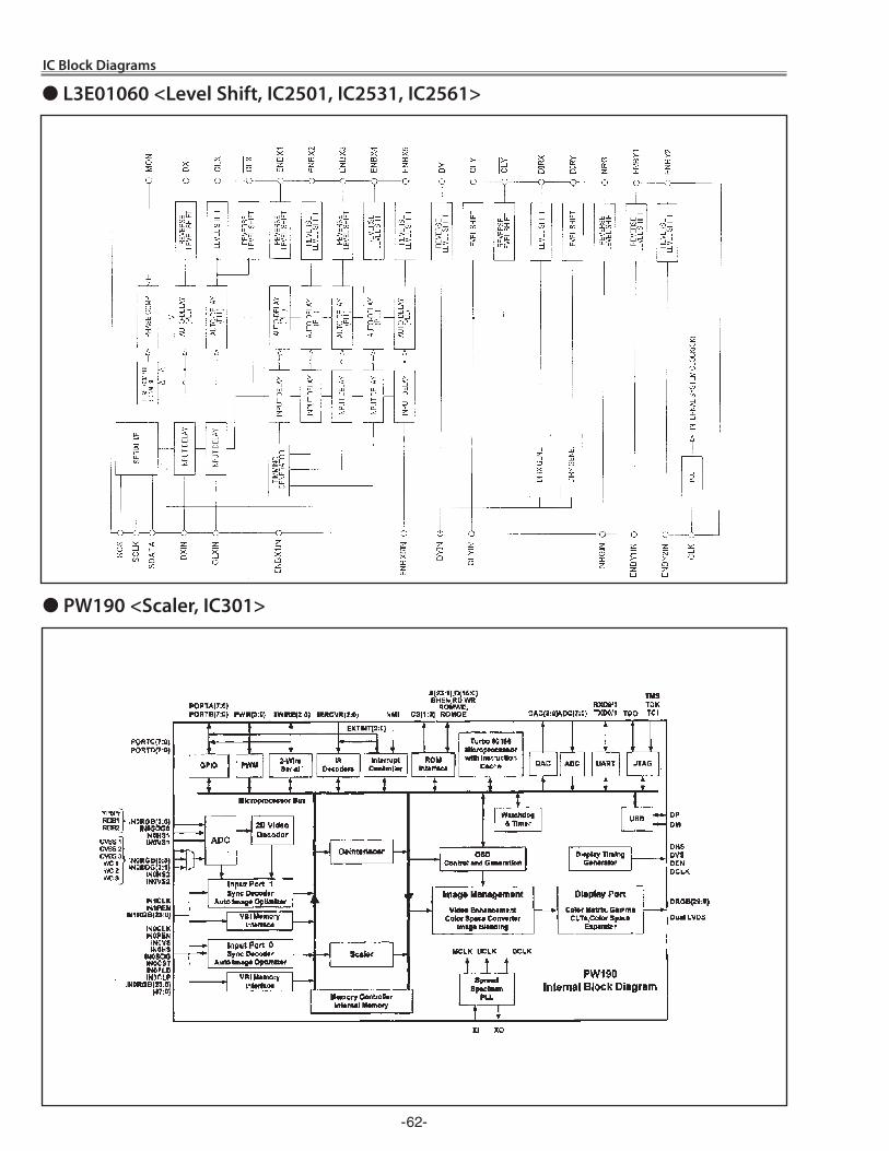
-6�-
IC Block Diagrams
● L3E01060 <Level Shift, IC2501, IC2531, IC2561>
● PW190 <Scaler, IC301>
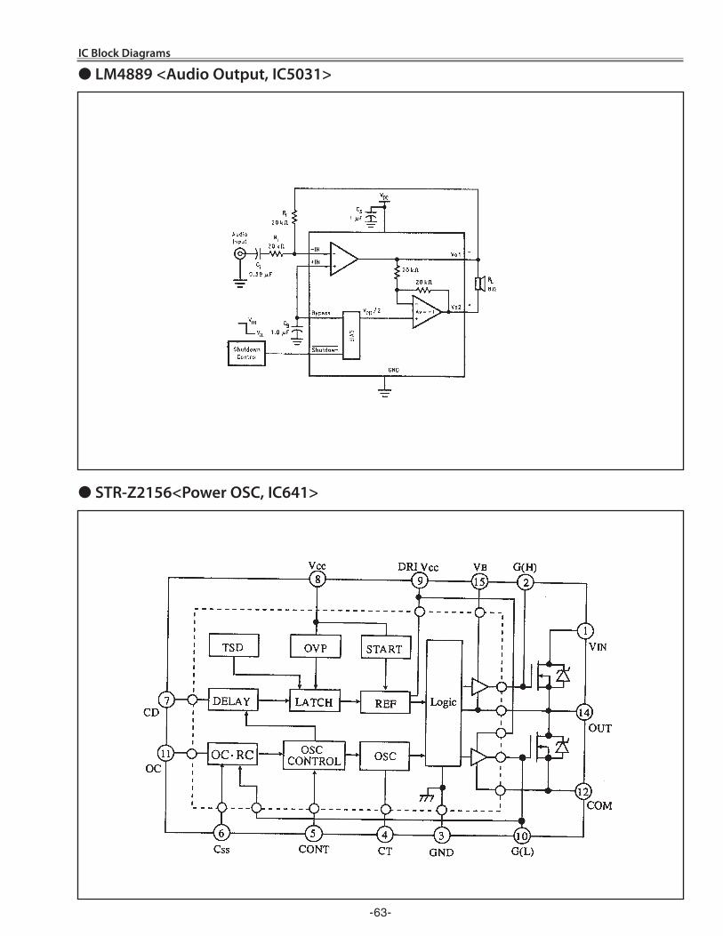
-63-
● LM4889 <Audio Output, IC5031>
● STR-Z2156<Power OSC, IC641>
IC Block Diagrams
KH3-XU7800,KZ3-XU7500
-64-
Product safety should be considered when a component replacement is made in any area of a projector. Components indicated by a ! mark in this parts list and the circuit diagram show components whose value have special significance to product safety. It is particularly recommended that only parts specified on the following parts list be used for components replacement pointed out by the mark.
Read description in the Capacitor and Resistor as follows:
cAPAcItor CERAMIC 100P K 50V
Rated Voltage
Tolerance Symbols:Less than 10pFA : Not specified B : ±0.1pF C : ±0.�5pFD : ±0.5pF E : +0 -1pF F : ±1PFG : ±�pF H : +0.1 -0pF L : +0 -0.1pFR : ±0.�5 -0pF S : +0-0.�5pFMore than 10pFA : Not specified B : ±0.1% C : ±0.�5%D : ±0.5% F : ±1% G : ±�%H : ±3% J : ±5% K : ±10%L : ±15% M : ±�0% N : ±30%P : +100-0% Q : +30-10% T : +50-10%U : +75-10% V : +�0-10% W : +100-10%X : +40-�0% Y : +150-10% Z : +80-�0%
Rated value: P=pico farad, U=micro faradMaterial:
CERAMIC........... CeramicMT-PAPER......... Metallized PaperPOLYESTER...... PolyesterMT-POLYEST.....Metallized PolyesterPOLYPRO.......... PolypropyleneMT-POLYPRO....Metallized PolypropyleneCOMPO FILM.....Composite filmMT-COMPO........Metallized CompositeSTYRENE...........StyreneTA-SOLID........... Tantalum Oxide Solid ElectrolyticAL-SOLID........... Aluminium Solid ElectrolyticELECT................Aluminum Foil ElectrolyticNP-ELECT..........Non-polarised ElectrolyticOS-SOLID.......... Aluminium Solid with Organic Semiconductive ElectrolyticPOS-SOLID........ Polymerized Organic SemiconductiveDL-ELECT.......... Double Layered ElectrolyticPPS-FILM...........Polyphenylene Sulfide FilmMT-PPS-FILM.....Metalized Polyphenylene Sulfide FilmMT-PEN-FILM.....Metalized Polyethylenenaphthalate FilmCAPACITOR.......Other
CARBON 4.7K J A 1/4WRated Wattage
Performance Symbols:A: General B: Non flammable Z: Low noiseOther: Temperature coefficient
Tolerance Symbols:A: ±0.05% B: ±0.1% C: ±0.�5% D: ±0.5%F: ±1% G: ±�% J: ±5% K: ±10%M: ±�0% P: +5-15% Z: 0 ohm
Rated value, ohms:K: 1,000, M: 1,000,000
Material:CARBON........... CarbonMT-FILM............ Metal FilmOXIDE-MT......... Oxide Metal FilmSOLID................ CompositionMT-GLAZE......... Metal GlazeWIRE WOUND...Wire WoundCERAMIC RES.. CeramicFUSIBLE RES....FusibleRESISTOR ........Other
T: ±10ppm/°C U: ±�5ppm/°C C: ±50ppm/°CD: ±100ppm/°C E: ±�00ppm/°C F: ±�50ppm/°CG: ±350ppm/°C H: ±1000ppm/°C±10% W: ±1�00ppm/°C±10%Y: ±1400ppm/°C±10% J: ±�000ppm/°C±10% K: ±�400ppm/°C±10%L: ±�700ppm/°C±10% M: ±3000ppm/°C±10% N: ±3300ppm/°C±10%P: ±3600ppm/°C±10% Q: ±3900ppm/°C±10% R: ±4�00ppm/°C±10%S: ±4300ppm/°C±10% V: ±4500ppm/°C±10% X: ±8000ppm/°C±10%
reSIStor
● read description in the parts list
Electrical Parts List
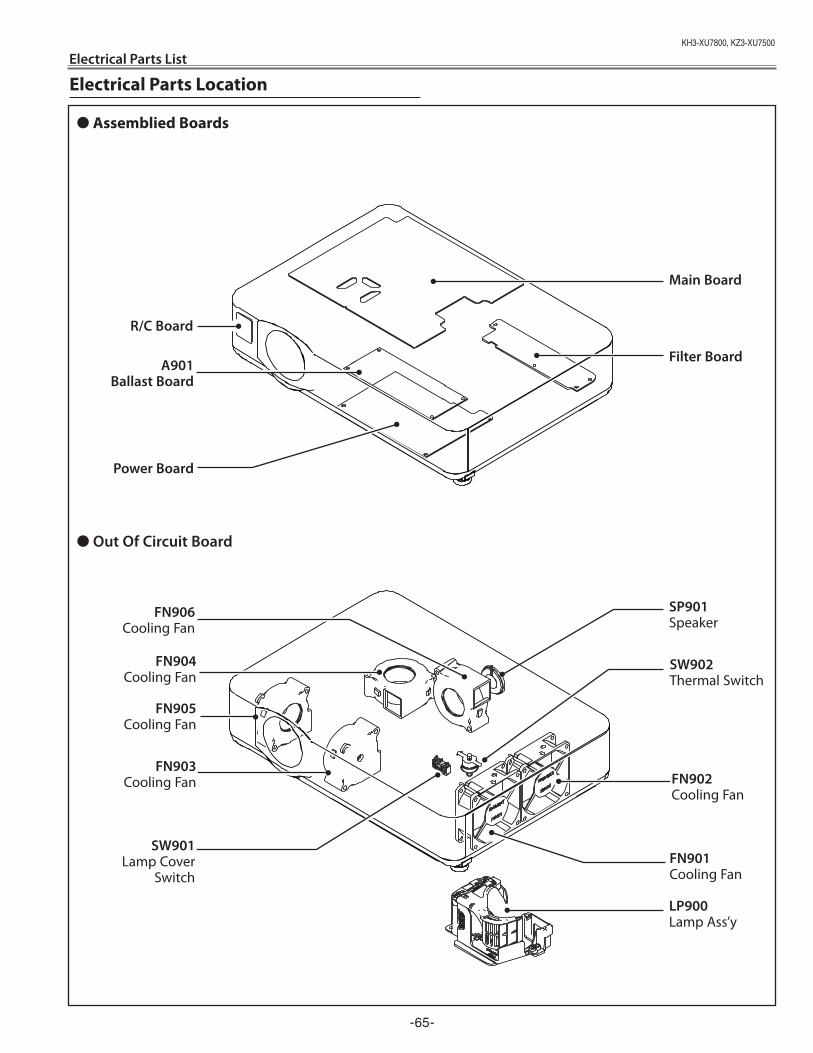
KH3-XU7800,KZ3-XU7500
-65-
Electrical Parts List
Electrical Parts Location
● Out Of Circuit Board
Main Board
● Assemblied Boards
FN906Cooling Fan
Filter BoardA901Ballast Board
R/C Board
FN902Cooling Fan
LP900Lamp Ass’y
Power Board
FN901Cooling Fan
SP901Speaker
FN903Cooling Fan
FN904Cooling Fan
FN905Cooling Fan
SW901Lamp Cover
Switch
SW902Thermal Switch
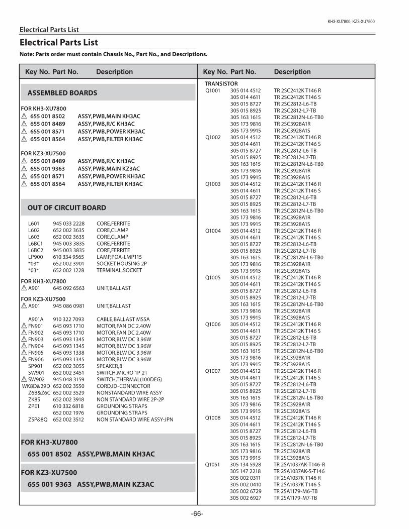
KH3-XU7800,KZ3-XU7500
Electrical Parts List
-66-
Electrical Parts ListNote: Parts order must contain Chassis No., Part No., and Descriptions.
Key No. Part No. description Key No. Part No. description
ASSEMBLED BOARDS FOR KH3-XU7800! 655 001 8502 ASSY,PWB,MAIN KH3AC! 655 001 8489 ASSY,PWB,R/C KH3AC! 655 001 8571 ASSY,PWB,POWER KH3AC! 655 001 8564 ASSY,PWB,FILTER KH3AC
FOR KZ3-XU7500! 655 001 8489 ASSY,PWB,R/C KH3AC! 655 001 9363 ASSY,PWB,MAIN KZ3AC! 655 001 8571 ASSY,PWB,POWER KH3AC ! 655 001 8564 ASSY,PWB,FILTER KH3AC
OUT OF CIRCUIT BOARD
L601 945 033 2228 CORE,FERRITE L602 652 002 3635 CORE,CLAMP L603 652 002 3635 CORE,CLAMP L6BC1 945 003 3835 CORE,FERRITE L6BC2 945 003 3835 CORE,FERRITE LP900 610 334 9565 LAMP,POA-LMP115 *03* 652 002 3901 SOCKET,HOUSING 2P *03* 652 002 1228 TERMINAL,SOCKET
FOR KH3-XU7800! A901 645 092 6563 UNIT,BALLAST
FOR KZ3-XU7500! A901 945 086 0981 UNIT,BALLAST
A901A 910 322 7093 CABLE,BALLAST MS5A! FN901 645 093 1710 MOTOR,FAN DC 2.40W! FN902 645 093 1710 MOTOR,FAN DC 2.40W! FN903 645 093 1345 MOTOR,BLW DC 3.96W! FN904 645 093 1345 MOTOR,BLW DC 3.96W! FN905 645 093 1338 MOTOR,BLW DC 3.96W! FN906 645 093 1345 MOTOR,BLW DC 3.96W SP901 652 002 3055 SPEAKER,8 SW901 652 002 3451 SWITCH,MICRO 1P-2T! SW902 945 048 3159 SWITCH,THERMAL(100DEG) WK8D&29D 652 002 3550 CORD,ID-CONNECTOR Z6B&Z6C 652 002 3529 NONSTANDARD WIRE ASSY ZK8S 652 002 3918 NON STANDARD WIRE 2P-2P ZPE1 610 332 6818 GROUNDING STRAPS 652 002 1976 GROUNDING STRAPS ZSP&8Q 652 002 3512 NON STANDARD WIRE ASSY-JPN
FOR KH3-XU7800
655 001 8502 ASSY,PWB,MAIN KH3AC
FOR KZ3-XU7500
655 001 9363 ASSY,PWB,MAIN KZ3AC
TRANSISTOR Q1001 305 014 4512 TR 2SC2412K T146 R 305 014 4611 TR 2SC2412K T146 S 305 015 8727 TR 2SC2812-L6-TB 305 015 8925 TR 2SC2812-L7-TB 305 163 1615 TR 2SC2812N-L6-TB0 305 173 9816 TR 2SC3928A1R 305 173 9915 TR 2SC3928A1S Q1002 305 014 4512 TR 2SC2412K T146 R 305 014 4611 TR 2SC2412K T146 S 305 015 8727 TR 2SC2812-L6-TB 305 015 8925 TR 2SC2812-L7-TB 305 163 1615 TR 2SC2812N-L6-TB0 305 173 9816 TR 2SC3928A1R 305 173 9915 TR 2SC3928A1S Q1003 305 014 4512 TR 2SC2412K T146 R 305 014 4611 TR 2SC2412K T146 S 305 015 8727 TR 2SC2812-L6-TB 305 015 8925 TR 2SC2812-L7-TB 305 163 1615 TR 2SC2812N-L6-TB0 305 173 9816 TR 2SC3928A1R 305 173 9915 TR 2SC3928A1S Q1004 305 014 4512 TR 2SC2412K T146 R 305 014 4611 TR 2SC2412K T146 S 305 015 8727 TR 2SC2812-L6-TB 305 015 8925 TR 2SC2812-L7-TB 305 163 1615 TR 2SC2812N-L6-TB0 305 173 9816 TR 2SC3928A1R 305 173 9915 TR 2SC3928A1S Q1005 305 014 4512 TR 2SC2412K T146 R 305 014 4611 TR 2SC2412K T146 S 305 015 8727 TR 2SC2812-L6-TB 305 015 8925 TR 2SC2812-L7-TB 305 163 1615 TR 2SC2812N-L6-TB0 305 173 9816 TR 2SC3928A1R 305 173 9915 TR 2SC3928A1S Q1006 305 014 4512 TR 2SC2412K T146 R 305 014 4611 TR 2SC2412K T146 S 305 015 8727 TR 2SC2812-L6-TB 305 015 8925 TR 2SC2812-L7-TB 305 163 1615 TR 2SC2812N-L6-TB0 305 173 9816 TR 2SC3928A1R 305 173 9915 TR 2SC3928A1S Q1007 305 014 4512 TR 2SC2412K T146 R 305 014 4611 TR 2SC2412K T146 S 305 015 8727 TR 2SC2812-L6-TB 305 015 8925 TR 2SC2812-L7-TB 305 163 1615 TR 2SC2812N-L6-TB0 305 173 9816 TR 2SC3928A1R 305 173 9915 TR 2SC3928A1S Q1008 305 014 4512 TR 2SC2412K T146 R 305 014 4611 TR 2SC2412K T146 S 305 015 8727 TR 2SC2812-L6-TB 305 015 8925 TR 2SC2812-L7-TB 305 163 1615 TR 2SC2812N-L6-TB0 305 173 9816 TR 2SC3928A1R 305 173 9915 TR 2SC3928A1S Q1051 305 134 5928 TR 2SA1037AK-T146-R 305 147 2218 TR 2SA1037AK-S-T146 305 002 0311 TR 2SA1037K T146 R 305 002 0410 TR 2SA1037K T146 S 305 002 6729 TR 2SA1179-M6-TB 305 002 6927 TR 2SA1179-M7-TB
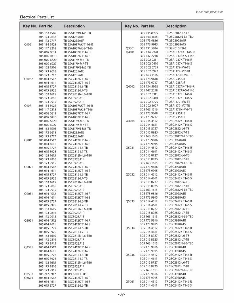
Key No. Part No. description Key No. Part No. description
KH3-XU7800,KZ3-XU7500
-67-
Electrical Parts List
305 163 1516 TR 2SA1179N-M6-TB 305 173 9618 TR 2SA1235A1E 305 173 9717 TR 2SA1235A1F Q1061 305 134 5928 TR 2SA1037AK-T146-R 305 147 2218 TR 2SA1037AK-S-T146 305 002 0311 TR 2SA1037K T146 R 305 002 0410 TR 2SA1037K T146 S 305 002 6729 TR 2SA1179-M6-TB 305 002 6927 TR 2SA1179-M7-TB 305 163 1516 TR 2SA1179N-M6-TB 305 173 9618 TR 2SA1235A1E 305 173 9717 TR 2SA1235A1F Q1062 305 014 4512 TR 2SC2412K T146 R 305 014 4611 TR 2SC2412K T146 S 305 015 8727 TR 2SC2812-L6-TB 305 015 8925 TR 2SC2812-L7-TB 305 163 1615 TR 2SC2812N-L6-TB0 305 173 9816 TR 2SC3928A1R 305 173 9915 TR 2SC3928A1S Q1071 305 134 5928 TR 2SA1037AK-T146-R 305 147 2218 TR 2SA1037AK-S-T146 305 002 0311 TR 2SA1037K T146 R 305 002 0410 TR 2SA1037K T146 S 305 002 6729 TR 2SA1179-M6-TB 305 002 6927 TR 2SA1179-M7-TB 305 163 1516 TR 2SA1179N-M6-TB 305 173 9618 TR 2SA1235A1E 305 173 9717 TR 2SA1235A1F Q2011 305 014 4512 TR 2SC2412K T146 R 305 014 4611 TR 2SC2412K T146 S 305 015 8727 TR 2SC2812-L6-TB 305 015 8925 TR 2SC2812-L7-TB 305 163 1615 TR 2SC2812N-L6-TB0 305 173 9816 TR 2SC3928A1R 305 173 9915 TR 2SC3928A1S Q2021 305 014 4512 TR 2SC2412K T146 R 305 014 4611 TR 2SC2412K T146 S 305 015 8727 TR 2SC2812-L6-TB 305 015 8925 TR 2SC2812-L7-TB 305 163 1615 TR 2SC2812N-L6-TB0 305 173 9816 TR 2SC3928A1R 305 173 9915 TR 2SC3928A1S Q2031 305 014 4512 TR 2SC2412K T146 R 305 014 4611 TR 2SC2412K T146 S 305 015 8727 TR 2SC2812-L6-TB 305 015 8925 TR 2SC2812-L7-TB 305 163 1615 TR 2SC2812N-L6-TB0 305 173 9816 TR 2SC3928A1R 305 173 9915 TR 2SC3928A1S Q3051 305 014 4512 TR 2SC2412K T146 R 305 014 4611 TR 2SC2412K T146 S 305 015 8727 TR 2SC2812-L6-TB 305 015 8925 TR 2SC2812-L7-TB 305 163 1615 TR 2SC2812N-L6-TB0 305 173 9816 TR 2SC3928A1R 305 173 9915 TR 2SC3928A1S Q3581 305 014 4512 TR 2SC2412K T146 R 305 014 4611 TR 2SC2412K T146 S 305 015 8727 TR 2SC2812-L6-TB 305 015 8925 TR 2SC2812-L7-TB 305 163 1615 TR 2SC2812N-L6-TB0 305 173 9816 TR 2SC3928A1R 305 173 9915 TR 2SC3928A1S Q3582 305 217 6917 TR TPC6107 TE85L Q3601 305 014 4512 TR 2SC2412K T146 R 305 014 4611 TR 2SC2412K T146 S 305 015 8727 TR 2SC2812-L6-TB
305 015 8925 TR 2SC2812-L7-TB 305 163 1615 TR 2SC2812N-L6-TB0 305 173 9816 TR 2SC3928A1R 305 173 9915 TR 2SC3928A1S Q3801 305 191 5814 TR 3LN01C-TB-E Q4011 305 134 5928 TR 2SA1037AK-T146-R 305 147 2218 TR 2SA1037AK-S-T146 305 002 0311 TR 2SA1037K T146 R 305 002 0410 TR 2SA1037K T146 S 305 002 6729 TR 2SA1179-M6-TB 305 002 6927 TR 2SA1179-M7-TB 305 163 1516 TR 2SA1179N-M6-TB 305 173 9618 TR 2SA1235A1E 305 173 9717 TR 2SA1235A1F Q4012 305 134 5928 TR 2SA1037AK-T146-R 305 147 2218 TR 2SA1037AK-S-T146 305 002 0311 TR 2SA1037K T146 R 305 002 0410 TR 2SA1037K T146 S 305 002 6729 TR 2SA1179-M6-TB 305 002 6927 TR 2SA1179-M7-TB 305 163 1516 TR 2SA1179N-M6-TB 305 173 9618 TR 2SA1235A1E 305 173 9717 TR 2SA1235A1F Q4014 305 014 4512 TR 2SC2412K T146 R 305 014 4611 TR 2SC2412K T146 S 305 015 8727 TR 2SC2812-L6-TB 305 015 8925 TR 2SC2812-L7-TB 305 163 1615 TR 2SC2812N-L6-TB0 305 173 9816 TR 2SC3928A1R 305 173 9915 TR 2SC3928A1S Q5031 305 014 4512 TR 2SC2412K T146 R 305 014 4611 TR 2SC2412K T146 S 305 015 8727 TR 2SC2812-L6-TB 305 015 8925 TR 2SC2812-L7-TB 305 163 1615 TR 2SC2812N-L6-TB0 305 173 9816 TR 2SC3928A1R 305 173 9915 TR 2SC3928A1S Q5032 305 014 4512 TR 2SC2412K T146 R 305 014 4611 TR 2SC2412K T146 S 305 015 8727 TR 2SC2812-L6-TB 305 015 8925 TR 2SC2812-L7-TB 305 163 1615 TR 2SC2812N-L6-TB0 305 173 9816 TR 2SC3928A1R 305 173 9915 TR 2SC3928A1S Q5033 305 014 4512 TR 2SC2412K T146 R 305 014 4611 TR 2SC2412K T146 S 305 015 8727 TR 2SC2812-L6-TB 305 015 8925 TR 2SC2812-L7-TB 305 163 1615 TR 2SC2812N-L6-TB0 305 173 9816 TR 2SC3928A1R 305 173 9915 TR 2SC3928A1S Q5034 305 014 4512 TR 2SC2412K T146 R 305 014 4611 TR 2SC2412K T146 S 305 015 8727 TR 2SC2812-L6-TB 305 015 8925 TR 2SC2812-L7-TB 305 163 1615 TR 2SC2812N-L6-TB0 305 173 9816 TR 2SC3928A1R 305 173 9915 TR 2SC3928A1S Q5036 305 014 4512 TR 2SC2412K T146 R 305 014 4611 TR 2SC2412K T146 S 305 015 8727 TR 2SC2812-L6-TB 305 015 8925 TR 2SC2812-L7-TB 305 163 1615 TR 2SC2812N-L6-TB0 305 173 9816 TR 2SC3928A1R 305 173 9915 TR 2SC3928A1S Q5061 305 014 4512 TR 2SC2412K T146 R 305 014 4611 TR 2SC2412K T146 S
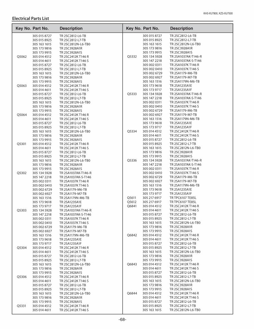
Key No. Part No. description Key No. Part No. description
KH3-XU7800,KZ3-XU7500
Electrical Parts List
-68-
305 015 8727 TR 2SC2812-L6-TB 305 015 8925 TR 2SC2812-L7-TB 305 163 1615 TR 2SC2812N-L6-TB0 305 173 9816 TR 2SC3928A1R 305 173 9915 TR 2SC3928A1S Q5062 305 014 4512 TR 2SC2412K T146 R 305 014 4611 TR 2SC2412K T146 S 305 015 8727 TR 2SC2812-L6-TB 305 015 8925 TR 2SC2812-L7-TB 305 163 1615 TR 2SC2812N-L6-TB0 305 173 9816 TR 2SC3928A1R 305 173 9915 TR 2SC3928A1S Q5063 305 014 4512 TR 2SC2412K T146 R 305 014 4611 TR 2SC2412K T146 S 305 015 8727 TR 2SC2812-L6-TB 305 015 8925 TR 2SC2812-L7-TB 305 163 1615 TR 2SC2812N-L6-TB0 305 173 9816 TR 2SC3928A1R 305 173 9915 TR 2SC3928A1S Q5064 305 014 4512 TR 2SC2412K T146 R 305 014 4611 TR 2SC2412K T146 S 305 015 8727 TR 2SC2812-L6-TB 305 015 8925 TR 2SC2812-L7-TB 305 163 1615 TR 2SC2812N-L6-TB0 305 173 9816 TR 2SC3928A1R 305 173 9915 TR 2SC3928A1S Q5301 305 014 4512 TR 2SC2412K T146 R 305 014 4611 TR 2SC2412K T146 S 305 015 8727 TR 2SC2812-L6-TB 305 015 8925 TR 2SC2812-L7-TB 305 163 1615 TR 2SC2812N-L6-TB0 305 173 9816 TR 2SC3928A1R 305 173 9915 TR 2SC3928A1S Q5302 305 134 5928 TR 2SA1037AK-T146-R 305 147 2218 TR 2SA1037AK-S-T146 305 002 0311 TR 2SA1037K T146 R 305 002 0410 TR 2SA1037K T146 S 305 002 6729 TR 2SA1179-M6-TB 305 002 6927 TR 2SA1179-M7-TB 305 163 1516 TR 2SA1179N-M6-TB 305 173 9618 TR 2SA1235A1E 305 173 9717 TR 2SA1235A1F Q5303 305 134 5928 TR 2SA1037AK-T146-R 305 147 2218 TR 2SA1037AK-S-T146 305 002 0311 TR 2SA1037K T146 R 305 002 0410 TR 2SA1037K T146 S 305 002 6729 TR 2SA1179-M6-TB 305 002 6927 TR 2SA1179-M7-TB 305 163 1516 TR 2SA1179N-M6-TB 305 173 9618 TR 2SA1235A1E 305 173 9717 TR 2SA1235A1F Q5304 305 014 4512 TR 2SC2412K T146 R 305 014 4611 TR 2SC2412K T146 S 305 015 8727 TR 2SC2812-L6-TB 305 015 8925 TR 2SC2812-L7-TB 305 163 1615 TR 2SC2812N-L6-TB0 305 173 9816 TR 2SC3928A1R 305 173 9915 TR 2SC3928A1S Q5306 305 014 4512 TR 2SC2412K T146 R 305 014 4611 TR 2SC2412K T146 S 305 015 8727 TR 2SC2812-L6-TB 305 015 8925 TR 2SC2812-L7-TB 305 163 1615 TR 2SC2812N-L6-TB0 305 173 9816 TR 2SC3928A1R 305 173 9915 TR 2SC3928A1S Q5331 305 014 4512 TR 2SC2412K T146 R 305 014 4611 TR 2SC2412K T146 S
305 015 8727 TR 2SC2812-L6-TB 305 015 8925 TR 2SC2812-L7-TB 305 163 1615 TR 2SC2812N-L6-TB0 305 173 9816 TR 2SC3928A1R 305 173 9915 TR 2SC3928A1S Q5332 305 134 5928 TR 2SA1037AK-T146-R 305 147 2218 TR 2SA1037AK-S-T146 305 002 0311 TR 2SA1037K T146 R 305 002 0410 TR 2SA1037K T146 S 305 002 6729 TR 2SA1179-M6-TB 305 002 6927 TR 2SA1179-M7-TB 305 163 1516 TR 2SA1179N-M6-TB 305 173 9618 TR 2SA1235A1E 305 173 9717 TR 2SA1235A1F Q5333 305 134 5928 TR 2SA1037AK-T146-R 305 147 2218 TR 2SA1037AK-S-T146 305 002 0311 TR 2SA1037K T146 R 305 002 0410 TR 2SA1037K T146 S 305 002 6729 TR 2SA1179-M6-TB 305 002 6927 TR 2SA1179-M7-TB 305 163 1516 TR 2SA1179N-M6-TB 305 173 9618 TR 2SA1235A1E 305 173 9717 TR 2SA1235A1F Q5334 305 014 4512 TR 2SC2412K T146 R 305 014 4611 TR 2SC2412K T146 S 305 015 8727 TR 2SC2812-L6-TB 305 015 8925 TR 2SC2812-L7-TB 305 163 1615 TR 2SC2812N-L6-TB0 305 173 9816 TR 2SC3928A1R 305 173 9915 TR 2SC3928A1S Q5336 305 134 5928 TR 2SA1037AK-T146-R 305 147 2218 TR 2SA1037AK-S-T146 305 002 0311 TR 2SA1037K T146 R 305 002 0410 TR 2SA1037K T146 S 305 002 6729 TR 2SA1179-M6-TB 305 002 6927 TR 2SA1179-M7-TB 305 163 1516 TR 2SA1179N-M6-TB 305 173 9618 TR 2SA1235A1E 305 173 9717 TR 2SA1235A1F Q5611 305 217 6917 TR TPC6107 TE85L Q5612 305 217 6917 TR TPC6107 TE85L Q6841 305 014 4512 TR 2SC2412K T146 R 305 014 4611 TR 2SC2412K T146 S 305 015 8727 TR 2SC2812-L6-TB 305 015 8925 TR 2SC2812-L7-TB 305 163 1615 TR 2SC2812N-L6-TB0 305 173 9816 TR 2SC3928A1R 305 173 9915 TR 2SC3928A1S Q6842 305 014 4512 TR 2SC2412K T146 R 305 014 4611 TR 2SC2412K T146 S 305 015 8727 TR 2SC2812-L6-TB 305 015 8925 TR 2SC2812-L7-TB 305 163 1615 TR 2SC2812N-L6-TB0 305 173 9816 TR 2SC3928A1R 305 173 9915 TR 2SC3928A1S Q6843 305 014 4512 TR 2SC2412K T146 R 305 014 4611 TR 2SC2412K T146 S 305 015 8727 TR 2SC2812-L6-TB 305 015 8925 TR 2SC2812-L7-TB 305 163 1615 TR 2SC2812N-L6-TB0 305 173 9816 TR 2SC3928A1R 305 173 9915 TR 2SC3928A1S Q6844 305 014 4512 TR 2SC2412K T146 R 305 014 4611 TR 2SC2412K T146 S 305 015 8727 TR 2SC2812-L6-TB 305 015 8925 TR 2SC2812-L7-TB 305 163 1615 TR 2SC2812N-L6-TB0
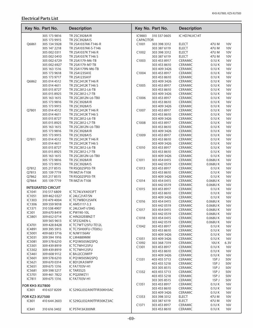
Key No. Part No. description Key No. Part No. description
KH3-XU7800,KZ3-XU7500
-69-
Electrical Parts List
305 173 9816 TR 2SC3928A1R 305 173 9915 TR 2SC3928A1S Q6861 305 134 5928 TR 2SA1037AK-T146-R 305 147 2218 TR 2SA1037AK-S-T146 305 002 0311 TR 2SA1037K T146 R 305 002 0410 TR 2SA1037K T146 S 305 002 6729 TR 2SA1179-M6-TB 305 002 6927 TR 2SA1179-M7-TB 305 163 1516 TR 2SA1179N-M6-TB 305 173 9618 TR 2SA1235A1E 305 173 9717 TR 2SA1235A1F Q6862 305 014 4512 TR 2SC2412K T146 R 305 014 4611 TR 2SC2412K T146 S 305 015 8727 TR 2SC2812-L6-TB 305 015 8925 TR 2SC2812-L7-TB 305 163 1615 TR 2SC2812N-L6-TB0 305 173 9816 TR 2SC3928A1R 305 173 9915 TR 2SC3928A1S Q7801 305 014 4512 TR 2SC2412K T146 R 305 014 4611 TR 2SC2412K T146 S 305 015 8727 TR 2SC2812-L6-TB 305 015 8925 TR 2SC2812-L7-TB 305 163 1615 TR 2SC2812N-L6-TB0 305 173 9816 TR 2SC3928A1R 305 173 9915 TR 2SC3928A1S Q7811 305 014 4512 TR 2SC2412K T146 R 305 014 4611 TR 2SC2412K T146 S 305 015 8727 TR 2SC2812-L6-TB 305 015 8925 TR 2SC2812-L7-TB 305 163 1615 TR 2SC2812N-L6-TB0 305 173 9816 TR 2SC3928A1R 305 173 9915 TR 2SC3928A1S Q7812 305 217 8515 TR RSQ025P03-TR Q7813 305 139 7719 TR IMZ1A-T108 Q7862 305 217 8515 TR RSQ025P03-TR Q7864 305 139 7719 TR IMZ1A-T108
INTEGRATED CIRCUIT IC1041 310 517 6809 IC TC74LVX4053FT IC1051 309 462 0327 IC 24LC21AT/SN IC1303 310 479 4004 IC TC7WBD125AFK IC1306 309 559 9018 IC AMS1117-3.3 IC1371 310 538 4907 IC 24LC64T-I/SNG IC301 309 670 8419 IC PW190-10L IC3801 309 652 0714 IC HIN202EIBNZ-T 309 565 9613 IC SP232AEN-L IC4701 309 428 8428 IC TC7WT125FU-TE12L IC4891 309 395 5915 IC TC7SH00FU-(TE85L) IC5001 409 683 5716 IC NJW1156AV IC5031 309 594 1916 IC LM4889MM IC5081 309 578 6210 IC PQ1M505M2SPQ IC5301 309 439 8919 IC TC7WH125FU IC5302 309 439 8919 IC TC7WH125FU IC5461 309 608 9112 IC BAJ2CC0WFP IC5601 309 578 6210 IC PQ1M505M2SPQ IC5621 309 670 0314 IC BD12KA5WFP IC5651 309 675 1316 IC FA7703V-H1 IC5681 309 598 5217 IC TAR5S25 IC5701 309 461 7822 IC PQ20WZ11 IC7811 309 675 1316 IC FA7703V-H1
FOR KH3-XU7800 IC801 410 637 8209 IC S29GL032A90TFIR30KH3AC
FOR KZ3-XU7500 IC801 410 644 2603 IC S29GL032A90TFIR30KZ3AC
IC841 310 616 3402 IC PST413A300NR
IC9883 310 337 0605 IC HD74LVC14T CAPACITOR C1001 303 398 3312 ELECT 47U M 10V 303 387 6119 ELECT 47U M 10V C1002 303 398 3312 ELECT 47U M 10V 303 387 6119 ELECT 47U M 10V C1003 303 453 8917 CERAMIC 0.1U K 16V 303 453 8610 CERAMIC 0.1U K 16V 303 409 3426 CERAMIC 0.1U K 16V C1004 303 453 8917 CERAMIC 0.1U K 16V 303 453 8610 CERAMIC 0.1U K 16V 303 409 3426 CERAMIC 0.1U K 16V C1005 303 453 8917 CERAMIC 0.1U K 16V 303 453 8610 CERAMIC 0.1U K 16V 303 409 3426 CERAMIC 0.1U K 16V C1006 303 453 8917 CERAMIC 0.1U K 16V 303 453 8610 CERAMIC 0.1U K 16V 303 409 3426 CERAMIC 0.1U K 16V C1007 303 453 8917 CERAMIC 0.1U K 16V 303 453 8610 CERAMIC 0.1U K 16V 303 409 3426 CERAMIC 0.1U K 16V C1008 303 453 8917 CERAMIC 0.1U K 16V 303 453 8610 CERAMIC 0.1U K 16V 303 409 3426 CERAMIC 0.1U K 16V C1009 303 453 8917 CERAMIC 0.1U K 16V 303 453 8610 CERAMIC 0.1U K 16V 303 409 3426 CERAMIC 0.1U K 16V C1010 303 453 8917 CERAMIC 0.1U K 16V 303 453 8610 CERAMIC 0.1U K 16V 303 409 3426 CERAMIC 0.1U K 16V C1011 303 454 0415 CERAMIC 0.068U K 16V 303 442 0519 CERAMIC 0.068U K 16V C1013 303 453 8917 CERAMIC 0.1U K 16V 303 453 8610 CERAMIC 0.1U K 16V 303 409 3426 CERAMIC 0.1U K 16V C1014 303 454 0415 CERAMIC 0.068U K 16V 303 442 0519 CERAMIC 0.068U K 16V C1015 303 453 8917 CERAMIC 0.1U K 16V 303 453 8610 CERAMIC 0.1U K 16V 303 409 3426 CERAMIC 0.1U K 16V C1016 303 454 0415 CERAMIC 0.068U K 16V 303 442 0519 CERAMIC 0.068U K 16V C1017 303 454 0415 CERAMIC 0.068U K 16V 303 442 0519 CERAMIC 0.068U K 16V C1018 303 454 0415 CERAMIC 0.068U K 16V 303 442 0519 CERAMIC 0.068U K 16V C1042 303 453 8917 CERAMIC 0.1U K 16V 303 453 8610 CERAMIC 0.1U K 16V 303 409 3426 CERAMIC 0.1U K 16V C1051 303 409 3426 CERAMIC 0.1U K 16V C1092 303 368 7319 CERAMIC 10U K 6.3V C1301 303 453 8917 CERAMIC 0.1U K 16V 303 453 8610 CERAMIC 0.1U K 16V 303 409 3426 CERAMIC 0.1U K 16V C1331 403 455 5713 CERAMIC 15P J 50V 403 455 5218 CERAMIC 15P J 50V 303 305 8515 CERAMIC 15P J 50V C1332 403 455 5713 CERAMIC 15P J 50V 403 455 5218 CERAMIC 15P J 50V 303 305 8515 CERAMIC 15P J 50V C1351 303 453 8917 CERAMIC 0.1U K 16V 303 453 8610 CERAMIC 0.1U K 16V 303 409 3426 CERAMIC 0.1U K 16V C1353 303 398 3312 ELECT 47U M 10V 303 387 6119 ELECT 47U M 10V C1371 303 453 8917 CERAMIC 0.1U K 16V 303 453 8610 CERAMIC 0.1U K 16V
Key No. Part No. description Key No. Part No. description
KH3-XU7800,KZ3-XU7500
Electrical Parts List
-70-
303 409 3426 CERAMIC 0.1U K 16V C1871 303 433 1112 CERAMIC 1U K 10V C2001 303 453 8610 CERAMIC 0.1U K 16V 303 409 3426 CERAMIC 0.1U K 16V C2002 303 449 1212 POS-SOLID 47U M 6.3V C2003 303 449 1212 POS-SOLID 47U M 6.3V C2504 303 453 8917 CERAMIC 0.1U K 16V 303 453 8610 CERAMIC 0.1U K 16V 303 409 3426 CERAMIC 0.1U K 16V C2505 303 376 3112 ELECT 100U M 25V C2506 403 461 3710 CERAMIC 0.1U Z 25V 303 454 0514 CERAMIC 0.1U Z 25V C2507 403 461 3710 CERAMIC 0.1U Z 25V 303 454 0514 CERAMIC 0.1U Z 25V C2509 303 453 8917 CERAMIC 0.1U K 16V 303 453 8610 CERAMIC 0.1U K 16V 303 409 3426 CERAMIC 0.1U K 16V C2511 303 453 8917 CERAMIC 0.1U K 16V 303 453 8610 CERAMIC 0.1U K 16V 303 409 3426 CERAMIC 0.1U K 16V C2512 303 433 1112 CERAMIC 1U K 10V C2513 403 461 3710 CERAMIC 0.1U Z 25V 303 454 0514 CERAMIC 0.1U Z 25V C2514 303 391 5511 ELECT 10U M 16V 303 175 7212 ELECT 10U M 16V C2534 303 453 8917 CERAMIC 0.1U K 16V 303 453 8610 CERAMIC 0.1U K 16V 303 409 3426 CERAMIC 0.1U K 16V C2535 303 376 3112 ELECT 100U M 25V C2536 403 461 3710 CERAMIC 0.1U Z 25V 303 454 0514 CERAMIC 0.1U Z 25V C2537 403 461 3710 CERAMIC 0.1U Z 25V 303 454 0514 CERAMIC 0.1U Z 25V C2539 303 453 8917 CERAMIC 0.1U K 16V 303 453 8610 CERAMIC 0.1U K 16V 303 409 3426 CERAMIC 0.1U K 16V C2541 303 453 8917 CERAMIC 0.1U K 16V 303 453 8610 CERAMIC 0.1U K 16V 303 409 3426 CERAMIC 0.1U K 16V C2542 303 433 1112 CERAMIC 1U K 10V C2543 403 461 3710 CERAMIC 0.1U Z 25V 303 454 0514 CERAMIC 0.1U Z 25V C2544 303 391 5511 ELECT 10U M 16V 303 175 7212 ELECT 10U M 16V C2564 303 453 8917 CERAMIC 0.1U K 16V 303 453 8610 CERAMIC 0.1U K 16V 303 409 3426 CERAMIC 0.1U K 16V C2565 303 376 3112 ELECT 100U M 25V C2566 403 461 3710 CERAMIC 0.1U Z 25V 303 454 0514 CERAMIC 0.1U Z 25V C2567 403 461 3710 CERAMIC 0.1U Z 25V 303 454 0514 CERAMIC 0.1U Z 25V C2569 303 453 8917 CERAMIC 0.1U K 16V 303 453 8610 CERAMIC 0.1U K 16V 303 409 3426 CERAMIC 0.1U K 16V C2571 303 453 8917 CERAMIC 0.1U K 16V 303 453 8610 CERAMIC 0.1U K 16V 303 409 3426 CERAMIC 0.1U K 16V C2572 303 433 1112 CERAMIC 1U K 10V C2573 403 461 3710 CERAMIC 0.1U Z 25V 303 454 0514 CERAMIC 0.1U Z 25V C2574 303 391 5511 ELECT 10U M 16V 303 175 7212 ELECT 10U M 16V C2891 303 453 8917 CERAMIC 0.1U K 16V 303 453 8610 CERAMIC 0.1U K 16V 303 409 3426 CERAMIC 0.1U K 16V C2892 303 453 7217 CERAMIC 47P J 50V
303 454 1610 CERAMIC 47P J 50V C301 303 453 8917 CERAMIC 0.1U K 16V 303 453 8610 CERAMIC 0.1U K 16V 303 409 3426 CERAMIC 0.1U K 16V C302 303 449 1212 POS-SOLID 47U M 6.3V C303 303 453 8719 CERAMIC 470P K 50V 303 453 9211 CERAMIC 470P K 50V 303 282 5118 CERAMIC 470P K 50V C304 303 453 8917 CERAMIC 0.1U K 16V 303 453 8610 CERAMIC 0.1U K 16V 303 409 3426 CERAMIC 0.1U K 16V C3051 303 453 6319 CERAMIC 100P J 50V 303 454 0910 CERAMIC 100P J 50V 303 294 6110 CERAMIC 100P J 50V C3052 303 372 7510 CERAMIC 2.2U K 6.3V 303 370 0216 CERAMIC 2.2U K 6.3V C3053 303 433 1112 CERAMIC 1U K 10V C306 303 453 8917 CERAMIC 0.1U K 16V 303 453 8610 CERAMIC 0.1U K 16V 303 409 3426 CERAMIC 0.1U K 16V C3061 303 453 6319 CERAMIC 100P J 50V 303 454 0910 CERAMIC 100P J 50V 303 294 6110 CERAMIC 100P J 50V C307 303 453 8719 CERAMIC 470P K 50V 303 453 9211 CERAMIC 470P K 50V 303 282 5118 CERAMIC 470P K 50V C308 303 453 8917 CERAMIC 0.1U K 16V 303 453 8610 CERAMIC 0.1U K 16V 303 409 3426 CERAMIC 0.1U K 16V C309 303 453 8917 CERAMIC 0.1U K 16V 303 453 8610 CERAMIC 0.1U K 16V 303 409 3426 CERAMIC 0.1U K 16V C310 303 449 1212 POS-SOLID 47U M 6.3V C311 303 453 8719 CERAMIC 470P K 50V 303 453 9211 CERAMIC 470P K 50V 303 282 5118 CERAMIC 470P K 50V C312 303 453 8917 CERAMIC 0.1U K 16V 303 453 8610 CERAMIC 0.1U K 16V 303 409 3426 CERAMIC 0.1U K 16V C313 303 453 8917 CERAMIC 0.1U K 16V 303 453 8610 CERAMIC 0.1U K 16V 303 409 3426 CERAMIC 0.1U K 16V C314 303 453 8719 CERAMIC 470P K 50V 303 453 9211 CERAMIC 470P K 50V 303 282 5118 CERAMIC 470P K 50V C315 303 449 1212 POS-SOLID 47U M 6.3V C316 303 453 8917 CERAMIC 0.1U K 16V 303 453 8610 CERAMIC 0.1U K 16V 303 409 3426 CERAMIC 0.1U K 16V C317 303 453 8917 CERAMIC 0.1U K 16V 303 453 8610 CERAMIC 0.1U K 16V 303 409 3426 CERAMIC 0.1U K 16V C318 303 453 8917 CERAMIC 0.1U K 16V 303 453 8610 CERAMIC 0.1U K 16V 303 409 3426 CERAMIC 0.1U K 16V C319 303 453 8719 CERAMIC 470P K 50V 303 453 9211 CERAMIC 470P K 50V 303 282 5118 CERAMIC 470P K 50V C320 303 449 1212 POS-SOLID 47U M 6.3V C321 303 453 8917 CERAMIC 0.1U K 16V 303 453 8610 CERAMIC 0.1U K 16V 303 409 3426 CERAMIC 0.1U K 16V C322 303 453 8917 CERAMIC 0.1U K 16V 303 453 8610 CERAMIC 0.1U K 16V 303 409 3426 CERAMIC 0.1U K 16V C323 303 453 8719 CERAMIC 470P K 50V 303 453 9211 CERAMIC 470P K 50V
Key No. Part No. description Key No. Part No. description
KH3-XU7800,KZ3-XU7500
-71-
Electrical Parts List
303 282 5118 CERAMIC 470P K 50V C324 303 453 8917 CERAMIC 0.1U K 16V 303 453 8610 CERAMIC 0.1U K 16V 303 409 3426 CERAMIC 0.1U K 16V C326 303 453 8917 CERAMIC 0.1U K 16V 303 453 8610 CERAMIC 0.1U K 16V 303 409 3426 CERAMIC 0.1U K 16V C327 303 453 8917 CERAMIC 0.1U K 16V 303 453 8610 CERAMIC 0.1U K 16V 303 409 3426 CERAMIC 0.1U K 16V C328 303 453 8917 CERAMIC 0.1U K 16V 303 453 8610 CERAMIC 0.1U K 16V 303 409 3426 CERAMIC 0.1U K 16V C329 303 453 8719 CERAMIC 470P K 50V 303 453 9211 CERAMIC 470P K 50V 303 282 5118 CERAMIC 470P K 50V C330 403 457 2512 CERAMIC 0.47U K 10V 303 376 6311 CERAMIC 0.47U K 10V C331 303 453 8917 CERAMIC 0.1U K 16V 303 453 8610 CERAMIC 0.1U K 16V 303 409 3426 CERAMIC 0.1U K 16V C332 303 453 8719 CERAMIC 470P K 50V 303 453 9211 CERAMIC 470P K 50V 303 282 5118 CERAMIC 470P K 50V C333 303 453 8917 CERAMIC 0.1U K 16V 303 453 8610 CERAMIC 0.1U K 16V 303 409 3426 CERAMIC 0.1U K 16V C334 303 453 8917 CERAMIC 0.1U K 16V 303 453 8610 CERAMIC 0.1U K 16V 303 409 3426 CERAMIC 0.1U K 16V C335 303 453 8917 CERAMIC 0.1U K 16V 303 453 8610 CERAMIC 0.1U K 16V 303 409 3426 CERAMIC 0.1U K 16V C336 303 453 8719 CERAMIC 470P K 50V 303 453 9211 CERAMIC 470P K 50V 303 282 5118 CERAMIC 470P K 50V C337 303 453 8917 CERAMIC 0.1U K 16V 303 453 8610 CERAMIC 0.1U K 16V 303 409 3426 CERAMIC 0.1U K 16V C338 303 453 8917 CERAMIC 0.1U K 16V 303 453 8610 CERAMIC 0.1U K 16V 303 409 3426 CERAMIC 0.1U K 16V C339 303 453 8917 CERAMIC 0.1U K 16V 303 453 8610 CERAMIC 0.1U K 16V 303 409 3426 CERAMIC 0.1U K 16V C341 303 453 8917 CERAMIC 0.1U K 16V 303 453 8610 CERAMIC 0.1U K 16V 303 409 3426 CERAMIC 0.1U K 16V C342 303 453 8917 CERAMIC 0.1U K 16V 303 453 8610 CERAMIC 0.1U K 16V 303 409 3426 CERAMIC 0.1U K 16V C343 303 453 8917 CERAMIC 0.1U K 16V 303 453 8610 CERAMIC 0.1U K 16V 303 409 3426 CERAMIC 0.1U K 16V C344 303 453 8917 CERAMIC 0.1U K 16V 303 453 8610 CERAMIC 0.1U K 16V 303 409 3426 CERAMIC 0.1U K 16V C346 303 453 8917 CERAMIC 0.1U K 16V 303 453 8610 CERAMIC 0.1U K 16V 303 409 3426 CERAMIC 0.1U K 16V C347 303 453 8917 CERAMIC 0.1U K 16V 303 453 8610 CERAMIC 0.1U K 16V 303 409 3426 CERAMIC 0.1U K 16V C348 303 453 8917 CERAMIC 0.1U K 16V 303 453 8610 CERAMIC 0.1U K 16V 303 409 3426 CERAMIC 0.1U K 16V C3501 403 461 3710 CERAMIC 0.1U Z 25V
303 454 0514 CERAMIC 0.1U Z 25V C3502 403 461 3710 CERAMIC 0.1U Z 25V 303 454 0514 CERAMIC 0.1U Z 25V C3503 303 376 3112 ELECT 100U M 25V C3505 303 376 3112 ELECT 100U M 25V C3506 403 461 3710 CERAMIC 0.1U Z 25V 303 454 0514 CERAMIC 0.1U Z 25V C3507 303 396 9613 CERAMIC 1U K 25V 303 397 7618 CERAMIC 1U K 25V C351 303 453 8917 CERAMIC 0.1U K 16V 303 453 8610 CERAMIC 0.1U K 16V 303 409 3426 CERAMIC 0.1U K 16V C352 303 453 8917 CERAMIC 0.1U K 16V 303 453 8610 CERAMIC 0.1U K 16V 303 409 3426 CERAMIC 0.1U K 16V C353 303 453 8917 CERAMIC 0.1U K 16V 303 453 8610 CERAMIC 0.1U K 16V 303 409 3426 CERAMIC 0.1U K 16V C3531 403 461 3710 CERAMIC 0.1U Z 25V 303 454 0514 CERAMIC 0.1U Z 25V C3532 403 461 3710 CERAMIC 0.1U Z 25V 303 454 0514 CERAMIC 0.1U Z 25V C3533 303 376 3112 ELECT 100U M 25V C3535 303 376 3112 ELECT 100U M 25V C3536 403 461 3710 CERAMIC 0.1U Z 25V 303 454 0514 CERAMIC 0.1U Z 25V C3537 303 396 9613 CERAMIC 1U K 25V 303 397 7618 CERAMIC 1U K 25V C354 303 453 8917 CERAMIC 0.1U K 16V 303 453 8610 CERAMIC 0.1U K 16V 303 409 3426 CERAMIC 0.1U K 16V C355 303 453 8917 CERAMIC 0.1U K 16V 303 453 8610 CERAMIC 0.1U K 16V 303 409 3426 CERAMIC 0.1U K 16V C356 303 453 8917 CERAMIC 0.1U K 16V 303 453 8610 CERAMIC 0.1U K 16V 303 409 3426 CERAMIC 0.1U K 16V C3561 403 461 3710 CERAMIC 0.1U Z 25V 303 454 0514 CERAMIC 0.1U Z 25V C3562 403 461 3710 CERAMIC 0.1U Z 25V 303 454 0514 CERAMIC 0.1U Z 25V C3563 303 376 3112 ELECT 100U M 25V C3565 303 376 3112 ELECT 100U M 25V C3566 403 461 3710 CERAMIC 0.1U Z 25V 303 454 0514 CERAMIC 0.1U Z 25V C3567 303 396 9613 CERAMIC 1U K 25V 303 397 7618 CERAMIC 1U K 25V C357 303 453 8917 CERAMIC 0.1U K 16V 303 453 8610 CERAMIC 0.1U K 16V 303 409 3426 CERAMIC 0.1U K 16V C358 303 453 8917 CERAMIC 0.1U K 16V 303 453 8610 CERAMIC 0.1U K 16V 303 409 3426 CERAMIC 0.1U K 16V C361 303 433 1112 CERAMIC 1U K 10V C362 303 433 1112 CERAMIC 1U K 10V C3626 403 461 3710 CERAMIC 0.1U Z 25V 303 454 0514 CERAMIC 0.1U Z 25V C363 303 433 1112 CERAMIC 1U K 10V C364 303 454 0613 CERAMIC 0.01U K 50V C365 303 454 0415 CERAMIC 0.068U K 16V 303 442 0519 CERAMIC 0.068U K 16V C366 303 453 8917 CERAMIC 0.1U K 16V 303 453 8610 CERAMIC 0.1U K 16V 303 409 3426 CERAMIC 0.1U K 16V C367 303 453 8917 CERAMIC 0.1U K 16V 303 453 8610 CERAMIC 0.1U K 16V 303 409 3426 CERAMIC 0.1U K 16V
Key No. Part No. description Key No. Part No. description
KH3-XU7800,KZ3-XU7500
Electrical Parts List
-7�-
C368 303 453 8917 CERAMIC 0.1U K 16V 303 453 8610 CERAMIC 0.1U K 16V 303 409 3426 CERAMIC 0.1U K 16V C369 303 453 8917 CERAMIC 0.1U K 16V 303 453 8610 CERAMIC 0.1U K 16V 303 409 3426 CERAMIC 0.1U K 16V C370 303 453 8917 CERAMIC 0.1U K 16V 303 453 8610 CERAMIC 0.1U K 16V 303 409 3426 CERAMIC 0.1U K 16V C371 303 453 8917 CERAMIC 0.1U K 16V 303 453 8610 CERAMIC 0.1U K 16V 303 409 3426 CERAMIC 0.1U K 16V C372 403 457 2512 CERAMIC 0.47U K 10V 303 376 6311 CERAMIC 0.47U K 10V C373 403 457 2512 CERAMIC 0.47U K 10V 303 376 6311 CERAMIC 0.47U K 10V C374 403 457 2512 CERAMIC 0.47U K 10V 303 376 6311 CERAMIC 0.47U K 10V C377 303 453 8917 CERAMIC 0.1U K 16V 303 453 8610 CERAMIC 0.1U K 16V 303 409 3426 CERAMIC 0.1U K 16V C378 303 453 8917 CERAMIC 0.1U K 16V 303 453 8610 CERAMIC 0.1U K 16V 303 409 3426 CERAMIC 0.1U K 16V C379 303 453 8917 CERAMIC 0.1U K 16V 303 453 8610 CERAMIC 0.1U K 16V 303 409 3426 CERAMIC 0.1U K 16V C380 303 453 8917 CERAMIC 0.1U K 16V 303 453 8610 CERAMIC 0.1U K 16V 303 409 3426 CERAMIC 0.1U K 16V C3801 303 453 8917 CERAMIC 0.1U K 16V 303 453 8610 CERAMIC 0.1U K 16V 303 409 3426 CERAMIC 0.1U K 16V C3802 303 453 8917 CERAMIC 0.1U K 16V 303 453 8610 CERAMIC 0.1U K 16V 303 409 3426 CERAMIC 0.1U K 16V C3803 303 453 8917 CERAMIC 0.1U K 16V 303 453 8610 CERAMIC 0.1U K 16V 303 409 3426 CERAMIC 0.1U K 16V C3804 303 453 8917 CERAMIC 0.1U K 16V 303 453 8610 CERAMIC 0.1U K 16V 303 409 3426 CERAMIC 0.1U K 16V C3806 303 433 1112 CERAMIC 1U K 10V C381 303 453 8917 CERAMIC 0.1U K 16V 303 453 8610 CERAMIC 0.1U K 16V 303 409 3426 CERAMIC 0.1U K 16V C382 303 453 8917 CERAMIC 0.1U K 16V 303 453 8610 CERAMIC 0.1U K 16V 303 409 3426 CERAMIC 0.1U K 16V C383 303 453 8719 CERAMIC 470P K 50V 303 453 9211 CERAMIC 470P K 50V 303 282 5118 CERAMIC 470P K 50V C384 303 453 8719 CERAMIC 470P K 50V 303 453 9211 CERAMIC 470P K 50V 303 282 5118 CERAMIC 470P K 50V C385 303 453 8719 CERAMIC 470P K 50V 303 453 9211 CERAMIC 470P K 50V 303 282 5118 CERAMIC 470P K 50V C4001 303 453 8917 CERAMIC 0.1U K 16V 303 453 8610 CERAMIC 0.1U K 16V 303 409 3426 CERAMIC 0.1U K 16V C4002 303 453 8917 CERAMIC 0.1U K 16V 303 453 8610 CERAMIC 0.1U K 16V 303 409 3426 CERAMIC 0.1U K 16V C401 303 453 8719 CERAMIC 470P K 50V 303 453 9211 CERAMIC 470P K 50V 303 282 5118 CERAMIC 470P K 50V
C402 303 453 8917 CERAMIC 0.1U K 16V 303 453 8610 CERAMIC 0.1U K 16V 303 409 3426 CERAMIC 0.1U K 16V C403 303 453 8719 CERAMIC 470P K 50V 303 453 9211 CERAMIC 470P K 50V 303 282 5118 CERAMIC 470P K 50V C404 303 453 8917 CERAMIC 0.1U K 16V 303 453 8610 CERAMIC 0.1U K 16V 303 409 3426 CERAMIC 0.1U K 16V C4057 303 398 3312 ELECT 47U M 10V 303 387 6119 ELECT 47U M 10V C406 303 453 8917 CERAMIC 0.1U K 16V 303 453 8610 CERAMIC 0.1U K 16V 303 409 3426 CERAMIC 0.1U K 16V C407 303 453 8719 CERAMIC 470P K 50V 303 453 9211 CERAMIC 470P K 50V 303 282 5118 CERAMIC 470P K 50V C411 303 453 8917 CERAMIC 0.1U K 16V 303 453 8610 CERAMIC 0.1U K 16V 303 409 3426 CERAMIC 0.1U K 16V C412 303 453 8917 CERAMIC 0.1U K 16V 303 453 8610 CERAMIC 0.1U K 16V 303 409 3426 CERAMIC 0.1U K 16V C413 303 453 8719 CERAMIC 470P K 50V 303 453 9211 CERAMIC 470P K 50V 303 282 5118 CERAMIC 470P K 50V C414 303 453 8917 CERAMIC 0.1U K 16V 303 453 8610 CERAMIC 0.1U K 16V 303 409 3426 CERAMIC 0.1U K 16V C416 303 453 8917 CERAMIC 0.1U K 16V 303 453 8610 CERAMIC 0.1U K 16V 303 409 3426 CERAMIC 0.1U K 16V C417 303 453 8719 CERAMIC 470P K 50V 303 453 9211 CERAMIC 470P K 50V 303 282 5118 CERAMIC 470P K 50V C421 303 453 8719 CERAMIC 470P K 50V 303 453 9211 CERAMIC 470P K 50V 303 282 5118 CERAMIC 470P K 50V C422 303 433 1112 CERAMIC 1U K 10V C423 303 453 8719 CERAMIC 470P K 50V 303 453 9211 CERAMIC 470P K 50V 303 282 5118 CERAMIC 470P K 50V C424 303 433 1112 CERAMIC 1U K 10V C426 303 433 1112 CERAMIC 1U K 10V C427 303 453 8719 CERAMIC 470P K 50V 303 453 9211 CERAMIC 470P K 50V 303 282 5118 CERAMIC 470P K 50V C431 303 453 8719 CERAMIC 470P K 50V 303 453 9211 CERAMIC 470P K 50V 303 282 5118 CERAMIC 470P K 50V C432 303 453 8917 CERAMIC 0.1U K 16V 303 453 8610 CERAMIC 0.1U K 16V 303 409 3426 CERAMIC 0.1U K 16V C433 303 453 8719 CERAMIC 470P K 50V 303 453 9211 CERAMIC 470P K 50V 303 282 5118 CERAMIC 470P K 50V C434 303 453 8917 CERAMIC 0.1U K 16V 303 453 8610 CERAMIC 0.1U K 16V 303 409 3426 CERAMIC 0.1U K 16V C436 303 453 8917 CERAMIC 0.1U K 16V 303 453 8610 CERAMIC 0.1U K 16V 303 409 3426 CERAMIC 0.1U K 16V C437 303 453 8719 CERAMIC 470P K 50V 303 453 9211 CERAMIC 470P K 50V 303 282 5118 CERAMIC 470P K 50V C438 303 449 1212 POS-SOLID 47U M 6.3V C439 303 453 8917 CERAMIC 0.1U K 16V
Key No. Part No. description Key No. Part No. description
KH3-XU7800,KZ3-XU7500
-73-
Electrical Parts List
303 453 8610 CERAMIC 0.1U K 16V 303 409 3426 CERAMIC 0.1U K 16V C471 303 433 1112 CERAMIC 1U K 10V C480 303 449 1212 POS-SOLID 47U M 6.3V C4808 303 449 1212 POS-SOLID 47U M 6.3V C481 303 449 1212 POS-SOLID 47U M 6.3V C482 303 449 1212 POS-SOLID 47U M 6.3V C483 303 449 1212 POS-SOLID 47U M 6.3V C4891 303 453 8917 CERAMIC 0.1U K 16V 303 453 8610 CERAMIC 0.1U K 16V 303 409 3426 CERAMIC 0.1U K 16V C5001 303 396 9613 CERAMIC 1U K 25V 303 397 7618 CERAMIC 1U K 25V C5002 303 396 9613 CERAMIC 1U K 25V 303 397 7618 CERAMIC 1U K 25V C5003 303 398 3312 ELECT 47U M 10V 303 387 6119 ELECT 47U M 10V C5004 303 396 9613 CERAMIC 1U K 25V 303 397 7618 CERAMIC 1U K 25V C5006 303 376 3112 ELECT 100U M 25V C5007 403 461 3710 CERAMIC 0.1U Z 25V 303 454 0514 CERAMIC 0.1U Z 25V C5008 303 453 8917 CERAMIC 0.1U K 16V 303 453 8610 CERAMIC 0.1U K 16V 303 409 3426 CERAMIC 0.1U K 16V C5009 303 396 9613 CERAMIC 1U K 25V 303 397 7618 CERAMIC 1U K 25V C501 303 453 8917 CERAMIC 0.1U K 16V 303 453 8610 CERAMIC 0.1U K 16V 303 409 3426 CERAMIC 0.1U K 16V C5011 303 394 5815 CERAMIC 4.7U K 16V C5012 303 394 5815 CERAMIC 4.7U K 16V C5013 303 394 5815 CERAMIC 4.7U K 16V C5014 303 396 9613 CERAMIC 1U K 25V 303 397 7618 CERAMIC 1U K 25V C502 303 453 8917 CERAMIC 0.1U K 16V 303 453 8610 CERAMIC 0.1U K 16V 303 409 3426 CERAMIC 0.1U K 16V C5024 303 379 6714 CERAMIC 10U K 16V C5025 303 391 5511 ELECT 10U M 16V 303 175 7212 ELECT 10U M 16V C5026 303 391 5511 ELECT 10U M 16V 303 175 7212 ELECT 10U M 16V C5027 303 391 5511 ELECT 10U M 16V 303 175 7212 ELECT 10U M 16V C5028 303 391 5511 ELECT 10U M 16V 303 175 7212 ELECT 10U M 16V C503 303 453 8917 CERAMIC 0.1U K 16V 303 453 8610 CERAMIC 0.1U K 16V 303 409 3426 CERAMIC 0.1U K 16V C5031 303 396 9613 CERAMIC 1U K 25V 303 397 7618 CERAMIC 1U K 25V C5032 303 336 3510 CERAMIC 0.47U K 16V C5033 303 433 1112 CERAMIC 1U K 10V C5037 303 433 1112 CERAMIC 1U K 10V C5038 303 454 0613 CERAMIC 0.01U K 50V C5039 303 454 0613 CERAMIC 0.01U K 50V C504 303 453 8917 CERAMIC 0.1U K 16V 303 453 8610 CERAMIC 0.1U K 16V 303 409 3426 CERAMIC 0.1U K 16V C5041 303 454 0613 CERAMIC 0.01U K 50V C505 303 396 9613 CERAMIC 1U K 25V 303 397 7618 CERAMIC 1U K 25V C506 403 461 3710 CERAMIC 0.1U Z 25V 303 454 0514 CERAMIC 0.1U Z 25V C5061 303 391 5511 ELECT 10U M 16V 303 175 7212 ELECT 10U M 16V
C5069 303 391 5511 ELECT 10U M 16V 303 175 7212 ELECT 10U M 16V C507 403 461 3710 CERAMIC 0.1U Z 25V 303 454 0514 CERAMIC 0.1U Z 25V C508 403 461 3710 CERAMIC 0.1U Z 25V 303 454 0514 CERAMIC 0.1U Z 25V C5081 303 453 8917 CERAMIC 0.1U K 16V 303 453 8610 CERAMIC 0.1U K 16V 303 409 3426 CERAMIC 0.1U K 16V C5082 303 453 8917 CERAMIC 0.1U K 16V 303 453 8610 CERAMIC 0.1U K 16V 303 409 3426 CERAMIC 0.1U K 16V C5083 303 392 1215 ELECT 47U M 6.3V 303 387 5310 ELECT 47U M 6.3V C5084 303 453 8917 CERAMIC 0.1U K 16V 303 453 8610 CERAMIC 0.1U K 16V 303 409 3426 CERAMIC 0.1U K 16V C5087 303 381 5613 ELECT 220U M 16V 303 423 8916 ELECT 220U M 16V C509 403 461 3710 CERAMIC 0.1U Z 25V 303 454 0514 CERAMIC 0.1U Z 25V C510 403 461 3710 CERAMIC 0.1U Z 25V 303 454 0514 CERAMIC 0.1U Z 25V C511 403 461 3710 CERAMIC 0.1U Z 25V 303 454 0514 CERAMIC 0.1U Z 25V C512 403 461 3710 CERAMIC 0.1U Z 25V 303 454 0514 CERAMIC 0.1U Z 25V C513 403 461 3710 CERAMIC 0.1U Z 25V 303 454 0514 CERAMIC 0.1U Z 25V C515 403 461 3710 CERAMIC 0.1U Z 25V 303 454 0514 CERAMIC 0.1U Z 25V C516 303 453 8511 CERAMIC 1000P K 50V 303 454 1214 CERAMIC 1000P K 50V C517 403 461 3710 CERAMIC 0.1U Z 25V 303 454 0514 CERAMIC 0.1U Z 25V C519 303 453 8917 CERAMIC 0.1U K 16V 303 453 8610 CERAMIC 0.1U K 16V 303 409 3426 CERAMIC 0.1U K 16V C524 303 391 5511 ELECT 10U M 16V 303 175 7212 ELECT 10U M 16V C529 303 453 8917 CERAMIC 0.1U K 16V 303 453 8610 CERAMIC 0.1U K 16V 303 409 3426 CERAMIC 0.1U K 16V C5303 303 372 7510 CERAMIC 2.2U K 6.3V 303 370 0216 CERAMIC 2.2U K 6.3V C5304 303 454 0415 CERAMIC 0.068U K 16V 303 442 0519 CERAMIC 0.068U K 16V C531 303 453 8917 CERAMIC 0.1U K 16V 303 453 8610 CERAMIC 0.1U K 16V 303 409 3426 CERAMIC 0.1U K 16V C5315 303 453 8917 CERAMIC 0.1U K 16V 303 453 8610 CERAMIC 0.1U K 16V 303 409 3426 CERAMIC 0.1U K 16V C5316 303 454 0415 CERAMIC 0.068U K 16V 303 442 0519 CERAMIC 0.068U K 16V C5317 303 453 8917 CERAMIC 0.1U K 16V 303 453 8610 CERAMIC 0.1U K 16V 303 409 3426 CERAMIC 0.1U K 16V C5318 303 433 1112 CERAMIC 1U K 10V C532 303 453 8917 CERAMIC 0.1U K 16V 303 453 8610 CERAMIC 0.1U K 16V 303 409 3426 CERAMIC 0.1U K 16V C533 303 453 8917 CERAMIC 0.1U K 16V 303 453 8610 CERAMIC 0.1U K 16V 303 409 3426 CERAMIC 0.1U K 16V C5331 303 372 7510 CERAMIC 2.2U K 6.3V 303 370 0216 CERAMIC 2.2U K 6.3V
Key No. Part No. description Key No. Part No. description
KH3-XU7800,KZ3-XU7500
Electrical Parts List
-74-
C5332 303 453 8917 CERAMIC 0.1U K 16V 303 453 8610 CERAMIC 0.1U K 16V 303 409 3426 CERAMIC 0.1U K 16V C5334 303 453 6814 CERAMIC 68P J 50V 303 454 0019 CERAMIC 68P J 50V C5336 403 456 4616 CERAMIC 27P J 50V 303 309 2519 CERAMIC 27P J 50V C5337 303 453 6319 CERAMIC 100P J 50V 303 454 0910 CERAMIC 100P J 50V 303 294 6110 CERAMIC 100P J 50V C534 303 453 8917 CERAMIC 0.1U K 16V 303 453 8610 CERAMIC 0.1U K 16V 303 409 3426 CERAMIC 0.1U K 16V C535 303 396 9613 CERAMIC 1U K 25V 303 397 7618 CERAMIC 1U K 25V C536 403 461 3710 CERAMIC 0.1U Z 25V 303 454 0514 CERAMIC 0.1U Z 25V C537 403 461 3710 CERAMIC 0.1U Z 25V 303 454 0514 CERAMIC 0.1U Z 25V C538 403 461 3710 CERAMIC 0.1U Z 25V 303 454 0514 CERAMIC 0.1U Z 25V C539 403 461 3710 CERAMIC 0.1U Z 25V 303 454 0514 CERAMIC 0.1U Z 25V C540 403 461 3710 CERAMIC 0.1U Z 25V 303 454 0514 CERAMIC 0.1U Z 25V C541 403 461 3710 CERAMIC 0.1U Z 25V 303 454 0514 CERAMIC 0.1U Z 25V C542 403 461 3710 CERAMIC 0.1U Z 25V 303 454 0514 CERAMIC 0.1U Z 25V C543 403 461 3710 CERAMIC 0.1U Z 25V 303 454 0514 CERAMIC 0.1U Z 25V C545 403 461 3710 CERAMIC 0.1U Z 25V 303 454 0514 CERAMIC 0.1U Z 25V C546 303 453 8511 CERAMIC 1000P K 50V 303 454 1214 CERAMIC 1000P K 50V C547 403 461 3710 CERAMIC 0.1U Z 25V 303 454 0514 CERAMIC 0.1U Z 25V C549 303 453 8917 CERAMIC 0.1U K 16V 303 453 8610 CERAMIC 0.1U K 16V 303 409 3426 CERAMIC 0.1U K 16V C554 303 391 5511 ELECT 10U M 16V 303 175 7212 ELECT 10U M 16V C559 303 453 8917 CERAMIC 0.1U K 16V 303 453 8610 CERAMIC 0.1U K 16V 303 409 3426 CERAMIC 0.1U K 16V C5601 303 398 3312 ELECT 47U M 10V 303 387 6119 ELECT 47U M 10V C5602 303 453 8917 CERAMIC 0.1U K 16V 303 453 8610 CERAMIC 0.1U K 16V 303 409 3426 CERAMIC 0.1U K 16V C5603 303 392 1215 ELECT 47U M 6.3V 303 387 5310 ELECT 47U M 6.3V C5604 303 453 8917 CERAMIC 0.1U K 16V 303 453 8610 CERAMIC 0.1U K 16V 303 409 3426 CERAMIC 0.1U K 16V C5605 303 453 8917 CERAMIC 0.1U K 16V 303 453 8610 CERAMIC 0.1U K 16V 303 409 3426 CERAMIC 0.1U K 16V C5606 303 453 8917 CERAMIC 0.1U K 16V 303 453 8610 CERAMIC 0.1U K 16V 303 409 3426 CERAMIC 0.1U K 16V C5607 303 409 3426 CERAMIC 0.1U K 16V C561 303 453 8917 CERAMIC 0.1U K 16V 303 453 8610 CERAMIC 0.1U K 16V 303 409 3426 CERAMIC 0.1U K 16V C562 303 453 8917 CERAMIC 0.1U K 16V 303 453 8610 CERAMIC 0.1U K 16V
303 409 3426 CERAMIC 0.1U K 16V C5621 303 453 8917 CERAMIC 0.1U K 16V 303 453 8610 CERAMIC 0.1U K 16V 303 409 3426 CERAMIC 0.1U K 16V C5622 303 392 1215 ELECT 47U M 6.3V 303 387 5310 ELECT 47U M 6.3V C5623 303 453 8917 CERAMIC 0.1U K 16V 303 453 8610 CERAMIC 0.1U K 16V 303 409 3426 CERAMIC 0.1U K 16V C563 303 453 8917 CERAMIC 0.1U K 16V 303 453 8610 CERAMIC 0.1U K 16V 303 409 3426 CERAMIC 0.1U K 16V C564 303 453 8917 CERAMIC 0.1U K 16V 303 453 8610 CERAMIC 0.1U K 16V 303 409 3426 CERAMIC 0.1U K 16V C5644 303 391 5511 ELECT 10U M 16V 303 175 7212 ELECT 10U M 16V C565 303 396 9613 CERAMIC 1U K 25V 303 397 7618 CERAMIC 1U K 25V C5651 303 454 1917 CERAMIC 4700P K 50V C5652 303 454 1917 CERAMIC 4700P K 50V C5655 303 453 8917 CERAMIC 0.1U K 16V 303 453 8610 CERAMIC 0.1U K 16V 303 409 3426 CERAMIC 0.1U K 16V C5659 303 453 8917 CERAMIC 0.1U K 16V 303 453 8610 CERAMIC 0.1U K 16V 303 409 3426 CERAMIC 0.1U K 16V C566 403 461 3710 CERAMIC 0.1U Z 25V 303 454 0514 CERAMIC 0.1U Z 25V C5661 303 453 8917 CERAMIC 0.1U K 16V 303 453 8610 CERAMIC 0.1U K 16V 303 409 3426 CERAMIC 0.1U K 16V C5662 303 453 8917 CERAMIC 0.1U K 16V 303 453 8610 CERAMIC 0.1U K 16V 303 409 3426 CERAMIC 0.1U K 16V C5664 303 392 1215 ELECT 47U M 6.3V 303 387 5310 ELECT 47U M 6.3V C5666 403 462 2910 EP-ELECT 330U M 4V C5667 303 381 5613 ELECT 220U M 16V 303 423 8916 ELECT 220U M 16V C5669 303 453 8917 CERAMIC 0.1U K 16V 303 453 8610 CERAMIC 0.1U K 16V 303 409 3426 CERAMIC 0.1U K 16V C567 403 461 3710 CERAMIC 0.1U Z 25V 303 454 0514 CERAMIC 0.1U Z 25V C5670 303 392 1215 ELECT 47U M 6.3V 303 387 5310 ELECT 47U M 6.3V C5671 303 381 5613 ELECT 220U M 16V 303 423 8916 ELECT 220U M 16V C5676 303 453 8917 CERAMIC 0.1U K 16V 303 453 8610 CERAMIC 0.1U K 16V 303 409 3426 CERAMIC 0.1U K 16V C568 403 461 3710 CERAMIC 0.1U Z 25V 303 454 0514 CERAMIC 0.1U Z 25V C5680 403 461 3710 CERAMIC 0.1U Z 25V 303 454 0514 CERAMIC 0.1U Z 25V C5681 403 462 2910 EP-ELECT 330U M 4V C5682 303 453 8917 CERAMIC 0.1U K 16V 303 453 8610 CERAMIC 0.1U K 16V 303 409 3426 CERAMIC 0.1U K 16V C5684 303 368 7319 CERAMIC 10U K 6.3V C569 403 461 3710 CERAMIC 0.1U Z 25V 303 454 0514 CERAMIC 0.1U Z 25V C570 403 461 3710 CERAMIC 0.1U Z 25V 303 454 0514 CERAMIC 0.1U Z 25V C5704 403 461 3710 CERAMIC 0.1U Z 25V 303 454 0514 CERAMIC 0.1U Z 25V
Key No. Part No. description Key No. Part No. description
KH3-XU7800,KZ3-XU7500
-75-
Electrical Parts List
C5705 303 376 3112 ELECT 100U M 25V C5706 303 376 3112 ELECT 100U M 25V C5709 303 376 3112 ELECT 100U M 25V C571 403 461 3710 CERAMIC 0.1U Z 25V 303 454 0514 CERAMIC 0.1U Z 25V C5710 403 461 3710 CERAMIC 0.1U Z 25V 303 454 0514 CERAMIC 0.1U Z 25V C572 403 461 3710 CERAMIC 0.1U Z 25V 303 454 0514 CERAMIC 0.1U Z 25V C573 403 461 3710 CERAMIC 0.1U Z 25V 303 454 0514 CERAMIC 0.1U Z 25V C575 403 461 3710 CERAMIC 0.1U Z 25V 303 454 0514 CERAMIC 0.1U Z 25V C576 303 453 8511 CERAMIC 1000P K 50V 303 454 1214 CERAMIC 1000P K 50V C577 403 461 3710 CERAMIC 0.1U Z 25V 303 454 0514 CERAMIC 0.1U Z 25V C579 303 453 8917 CERAMIC 0.1U K 16V 303 453 8610 CERAMIC 0.1U K 16V 303 409 3426 CERAMIC 0.1U K 16V C584 303 391 5511 ELECT 10U M 16V 303 175 7212 ELECT 10U M 16V C589 303 453 8917 CERAMIC 0.1U K 16V 303 453 8610 CERAMIC 0.1U K 16V 303 409 3426 CERAMIC 0.1U K 16V C6801 303 453 8917 CERAMIC 0.1U K 16V 303 453 8610 CERAMIC 0.1U K 16V 303 409 3426 CERAMIC 0.1U K 16V C6802 303 453 8917 CERAMIC 0.1U K 16V 303 453 8610 CERAMIC 0.1U K 16V 303 409 3426 CERAMIC 0.1U K 16V C6803 303 453 8917 CERAMIC 0.1U K 16V 303 453 8610 CERAMIC 0.1U K 16V 303 409 3426 CERAMIC 0.1U K 16V C6861 303 433 1112 CERAMIC 1U K 10V C7811 303 397 8219 CERAMIC 2.2U K 25V C7812 403 461 3710 CERAMIC 0.1U Z 25V 303 454 0514 CERAMIC 0.1U Z 25V C7813 303 381 5613 ELECT 220U M 16V 303 423 8916 ELECT 220U M 16V C7816 303 376 3112 ELECT 100U M 25V C7817 303 453 8917 CERAMIC 0.1U K 16V 303 453 8610 CERAMIC 0.1U K 16V 303 409 3426 CERAMIC 0.1U K 16V C7818 303 454 1917 CERAMIC 4700P K 50V C7863 303 381 5613 ELECT 220U M 16V 303 423 8916 ELECT 220U M 16V C7868 303 454 1917 CERAMIC 4700P K 50V C801 303 453 8917 CERAMIC 0.1U K 16V 303 453 8610 CERAMIC 0.1U K 16V 303 409 3426 CERAMIC 0.1U K 16V C841 303 433 1112 CERAMIC 1U K 10V C842 303 392 1215 ELECT 47U M 6.3V 303 387 5310 ELECT 47U M 6.3V C843 303 454 0613 CERAMIC 0.01U K 50V C844 303 453 8511 CERAMIC 1000P K 50V 303 454 1214 CERAMIC 1000P K 50V C8813 303 453 8917 CERAMIC 0.1U K 16V 303 453 8610 CERAMIC 0.1U K 16V 303 409 3426 CERAMIC 0.1U K 16V C8823 303 453 8917 CERAMIC 0.1U K 16V 303 453 8610 CERAMIC 0.1U K 16V 303 409 3426 CERAMIC 0.1U K 16V C9882 303 453 8917 CERAMIC 0.1U K 16V 303 453 8610 CERAMIC 0.1U K 16V 303 409 3426 CERAMIC 0.1U K 16V
RESISTOR R1001 301 260 4115 MT-GLAZE 75 JA 1/3W R1002 301 224 8814 MT-GLAZE 100 JA 1/16W R1003 301 225 8110 MT-GLAZE 10 JA 1/16W R1004 301 225 8110 MT-GLAZE 10 JA 1/16W R1005 301 225 0312 MT-GLAZE 33 JA 1/16W R1011 301 260 4115 MT-GLAZE 75 JA 1/3W R1012 301 224 8814 MT-GLAZE 100 JA 1/16W R1021 301 260 4115 MT-GLAZE 75 JA 1/3W R1022 301 224 8814 MT-GLAZE 100 JA 1/16W R1031 301 225 1418 MT-GLAZE 47K JA 1/16W R1033 301 225 1814 MT-GLAZE 47 JA 1/16W R1034 301 225 1814 MT-GLAZE 47 JA 1/16W R1036 301 225 1814 MT-GLAZE 47 JA 1/16W R1037 301 225 1814 MT-GLAZE 47 JA 1/16W R1038 301 224 8814 MT-GLAZE 100 JA 1/16W R1039 301 225 1814 MT-GLAZE 47 JA 1/16W R1040 301 225 3818 MT-GLAZE 1.5K JA 1/16W R1041 301 225 1418 MT-GLAZE 47K JA 1/16W R1043 301 226 1516 MT-GLAZE 0.000 ZA 1/16W R1044 301 224 9019 MT-GLAZE 10K JA 1/16W R1045 301 226 1516 MT-GLAZE 0.000 ZA 1/16W R1046 301 226 1516 MT-GLAZE 0.000 ZA 1/16W R1047 301 226 1516 MT-GLAZE 0.000 ZA 1/16W R1048 301 224 8814 MT-GLAZE 100 JA 1/16W R1049 301 226 1516 MT-GLAZE 0.000 ZA 1/16W R1050 301 225 3818 MT-GLAZE 1.5K JA 1/16W R1051 301 260 4115 MT-GLAZE 75 JA 1/3W R1052 301 263 7420 MT-GLAZE 75 JA 1/16W R1053 301 225 2019 MT-GLAZE 680 JA 1/16W R1054 301 224 9316 MT-GLAZE 1K JA 1/16W R1055 301 225 1210 MT-GLAZE 4.7K JA 1/16W R1057 301 225 1210 MT-GLAZE 4.7K JA 1/16W R1058 301 224 9316 MT-GLAZE 1K JA 1/16W R1060 301 225 3818 MT-GLAZE 1.5K JA 1/16W R1061 301 260 4115 MT-GLAZE 75 JA 1/3W R1062 301 263 7420 MT-GLAZE 75 JA 1/16W R1063 301 225 2019 MT-GLAZE 680 JA 1/16W R1064 301 224 9316 MT-GLAZE 1K JA 1/16W R1065 301 225 3818 MT-GLAZE 1.5K JA 1/16W R1067 301 224 9019 MT-GLAZE 10K JA 1/16W R1068 301 224 9019 MT-GLAZE 10K JA 1/16W R1069 301 224 9316 MT-GLAZE 1K JA 1/16W R1070 301 263 7420 MT-GLAZE 75 JA 1/16W R1071 301 260 4115 MT-GLAZE 75 JA 1/3W R1072 301 263 7420 MT-GLAZE 75 JA 1/16W R1073 301 225 2019 MT-GLAZE 680 JA 1/16W R1074 301 224 9316 MT-GLAZE 1K JA 1/16W R1075 301 263 7420 MT-GLAZE 75 JA 1/16W R1077 301 263 7420 MT-GLAZE 75 JA 1/16W R1078 301 263 7420 MT-GLAZE 75 JA 1/16W R1079 301 263 7420 MT-GLAZE 75 JA 1/16W R1080 301 263 7420 MT-GLAZE 75 JA 1/16W R1081 301 225 1418 MT-GLAZE 47K JA 1/16W R1083 301 225 1814 MT-GLAZE 47 JA 1/16W R1084 301 225 3818 MT-GLAZE 1.5K JA 1/16W R1088 301 225 3818 MT-GLAZE 1.5K JA 1/16W R1091 301 225 1418 MT-GLAZE 47K JA 1/16W R1309 301 225 1210 MT-GLAZE 4.7K JA 1/16W R1311 301 225 1210 MT-GLAZE 4.7K JA 1/16W R1331 301 224 9415 MT-GLAZE 1M JA 1/16W R2002 301 224 8814 MT-GLAZE 100 JA 1/16W R2004 301 037 5017 MT-GLAZE 0.000 ZA 1/10W R2006 301 037 5116 MT-GLAZE 10 JA 1/10W R2007 301 037 5116 MT-GLAZE 10 JA 1/10W R2011 301 224 8814 MT-GLAZE 100 JA 1/16W R2012 301 260 4115 MT-GLAZE 75 JA 1/3W
Key No. Part No. description Key No. Part No. description
KH3-XU7800,KZ3-XU7500
Electrical Parts List
-76-
R2016 301 225 3818 MT-GLAZE 1.5K JA 1/16W R2021 301 224 8814 MT-GLAZE 100 JA 1/16W R2022 301 260 4115 MT-GLAZE 75 JA 1/3W R2026 301 225 3818 MT-GLAZE 1.5K JA 1/16W R2032 301 260 4115 MT-GLAZE 75 JA 1/3W R2034 301 224 8814 MT-GLAZE 100 JA 1/16W R2036 301 225 3818 MT-GLAZE 1.5K JA 1/16W R2043 301 224 8814 MT-GLAZE 100 JA 1/16W R2053 301 224 8814 MT-GLAZE 100 JA 1/16W R2501 301 150 6014 MT-GLAZE 0.000 ZA 1/10W R2508 301 226 1516 MT-GLAZE 0.000 ZA 1/16W R2509 301 226 1516 MT-GLAZE 0.000 ZA 1/16W R2510 301 226 1516 MT-GLAZE 0.000 ZA 1/16W R2511 301 226 1516 MT-GLAZE 0.000 ZA 1/16W R2512 301 226 1516 MT-GLAZE 0.000 ZA 1/16W R2513 301 226 1516 MT-GLAZE 0.000 ZA 1/16W R2514 301 226 1516 MT-GLAZE 0.000 ZA 1/16W R2515 301 226 1516 MT-GLAZE 0.000 ZA 1/16W R2516 301 226 1516 MT-GLAZE 0.000 ZA 1/16W R2517 301 226 1516 MT-GLAZE 0.000 ZA 1/16W R2518 301 226 1516 MT-GLAZE 0.000 ZA 1/16W R2519 301 226 1516 MT-GLAZE 0.000 ZA 1/16W R2521 301 224 8913 MT-GLAZE 100K JA 1/16W R2523 301 226 1516 MT-GLAZE 0.000 ZA 1/16W R2525 301 226 1516 MT-GLAZE 0.000 ZA 1/16W R2527 301 226 1516 MT-GLAZE 0.000 ZA 1/16W R2531 301 150 6014 MT-GLAZE 0.000 ZA 1/10W R2532 301 226 1516 MT-GLAZE 0.000 ZA 1/16W R2533 301 226 1516 MT-GLAZE 0.000 ZA 1/16W R2534 301 226 1516 MT-GLAZE 0.000 ZA 1/16W R2535 301 226 1516 MT-GLAZE 0.000 ZA 1/16W R2536 301 226 1516 MT-GLAZE 0.000 ZA 1/16W R2537 301 226 1516 MT-GLAZE 0.000 ZA 1/16W R2538 301 226 1516 MT-GLAZE 0.000 ZA 1/16W R2539 301 226 1516 MT-GLAZE 0.000 ZA 1/16W R2540 301 226 1516 MT-GLAZE 0.000 ZA 1/16W R2551 301 224 8913 MT-GLAZE 100K JA 1/16W R2561 301 150 6014 MT-GLAZE 0.000 ZA 1/10W R2581 301 224 8913 MT-GLAZE 100K JA 1/16W R2890 301 224 9712 MT-GLAZE 22 JA 1/16W R2892 301 224 8814 MT-GLAZE 100 JA 1/16W R300 301 224 9019 MT-GLAZE 10K JA 1/16W R3002 301 224 8814 MT-GLAZE 100 JA 1/16W R3012 301 224 8814 MT-GLAZE 100 JA 1/16W R302 301 227 5612 MT-GLAZE 8.2K JA 1/16W R303 301 224 9316 MT-GLAZE 1K JA 1/16W R304 301 224 9316 MT-GLAZE 1K JA 1/16W R3051 301 224 8913 MT-GLAZE 100K JA 1/16W R3052 301 224 8814 MT-GLAZE 100 JA 1/16W R3053 301 224 8913 MT-GLAZE 100K JA 1/16W R3054 301 224 8913 MT-GLAZE 100K JA 1/16W R3056 301 224 9415 MT-GLAZE 1M JA 1/16W R3057 301 224 9910 MT-GLAZE 22K JA 1/16W R306 401 342 7314 MT-GLAZE 23.2K FA 1/16W R3061 301 224 8913 MT-GLAZE 100K JA 1/16W R3062 301 224 8814 MT-GLAZE 100 JA 1/16W R307 301 224 9712 MT-GLAZE 22 JA 1/16W R308 301 224 9712 MT-GLAZE 22 JA 1/16W R309 301 224 9316 MT-GLAZE 1K JA 1/16W R311 301 224 9316 MT-GLAZE 1K JA 1/16W R312 301 226 1516 MT-GLAZE 0.000 ZA 1/16W R313 301 226 1516 MT-GLAZE 0.000 ZA 1/16W R314 301 226 1516 MT-GLAZE 0.000 ZA 1/16W R315 301 226 1516 MT-GLAZE 0.000 ZA 1/16W R316 301 226 1516 MT-GLAZE 0.000 ZA 1/16W R318 301 226 1516 MT-GLAZE 0.000 ZA 1/16W R319 301 224 9019 MT-GLAZE 10K JA 1/16W
R320 301 225 0817 MT-GLAZE 68K JA 1/16W R321 301 225 0213 MT-GLAZE 3.3K JA 1/16W R322 301 225 0213 MT-GLAZE 3.3K JA 1/16W R323 301 224 9019 MT-GLAZE 10K JA 1/16W R324 301 224 9217 MT-GLAZE 15K JA 1/16W R325 301 224 9019 MT-GLAZE 10K JA 1/16W R339 301 225 0213 MT-GLAZE 3.3K JA 1/16W R340 301 224 8814 MT-GLAZE 100 JA 1/16W R341 301 225 0213 MT-GLAZE 3.3K JA 1/16W R342 301 225 0213 MT-GLAZE 3.3K JA 1/16W R343 301 225 0213 MT-GLAZE 3.3K JA 1/16W R347 301 224 8814 MT-GLAZE 100 JA 1/16W R348 301 225 8110 MT-GLAZE 10 JA 1/16W R349 301 226 1516 MT-GLAZE 0.000 ZA 1/16W R350 301 263 7420 MT-GLAZE 75 JA 1/16W R3502 301 225 1418 MT-GLAZE 47K JA 1/16W R3503 301 224 8913 MT-GLAZE 100K JA 1/16W R3505 301 225 8110 MT-GLAZE 10 JA 1/16W R3506 301 225 8110 MT-GLAZE 10 JA 1/16W R351 301 225 8110 MT-GLAZE 10 JA 1/16W R352 301 226 1516 MT-GLAZE 0.000 ZA 1/16W R353 301 263 7420 MT-GLAZE 75 JA 1/16W R3532 301 225 1418 MT-GLAZE 47K JA 1/16W R3533 301 224 8913 MT-GLAZE 100K JA 1/16W R354 301 224 8814 MT-GLAZE 100 JA 1/16W R355 301 224 8814 MT-GLAZE 100 JA 1/16W R356 301 226 1516 MT-GLAZE 0.000 ZA 1/16W R3562 301 225 1418 MT-GLAZE 47K JA 1/16W R3563 301 224 8913 MT-GLAZE 100K JA 1/16W R357 301 226 1516 MT-GLAZE 0.000 ZA 1/16W R3580 301 037 5017 MT-GLAZE 0.000 ZA 1/10W R3581 301 224 9019 MT-GLAZE 10K JA 1/16W R3582 303 433 1112 CERAMIC 1U K 10V R3583 301 224 9316 MT-GLAZE 1K JA 1/16W R3584 301 224 9019 MT-GLAZE 10K JA 1/16W R359 301 225 0015 MT-GLAZE 270 JA 1/16W R360 301 225 0015 MT-GLAZE 270 JA 1/16W R3601 301 225 0213 MT-GLAZE 3.3K JA 1/16W R3602 301 224 9019 MT-GLAZE 10K JA 1/16W R3603 301 224 9019 MT-GLAZE 10K JA 1/16W R361 301 256 1517 MT-GLAZE 13K JA 1/10W 301 113 6914 MT-GLAZE 13K JA 1/16W R3621 301 224 9019 MT-GLAZE 10K JA 1/16W R3622 301 224 9019 MT-GLAZE 10K JA 1/16W R3623 301 224 9019 MT-GLAZE 10K JA 1/16W R3624 301 224 9019 MT-GLAZE 10K JA 1/16W R3626 301 224 9019 MT-GLAZE 10K JA 1/16W R3627 301 224 9019 MT-GLAZE 10K JA 1/16W R363 301 224 9316 MT-GLAZE 1K JA 1/16W R364 301 224 9316 MT-GLAZE 1K JA 1/16W R366 301 224 9316 MT-GLAZE 1K JA 1/16W R367 301 226 1516 MT-GLAZE 0.000 ZA 1/16W R371 301 225 8110 MT-GLAZE 10 JA 1/16W R372 301 225 8110 MT-GLAZE 10 JA 1/16W R373 301 225 8110 MT-GLAZE 10 JA 1/16W R374 301 225 8110 MT-GLAZE 10 JA 1/16W R378 301 224 9019 MT-GLAZE 10K JA 1/16W R380 301 224 9019 MT-GLAZE 10K JA 1/16W R3801 301 225 8110 MT-GLAZE 10 JA 1/16W R3802 301 225 8110 MT-GLAZE 10 JA 1/16W R3803 301 225 8110 MT-GLAZE 10 JA 1/16W R3804 301 225 8110 MT-GLAZE 10 JA 1/16W R3806 301 225 0213 MT-GLAZE 3.3K JA 1/16W R382 301 263 7420 MT-GLAZE 75 JA 1/16W R383 301 224 8814 MT-GLAZE 100 JA 1/16W R384 301 224 8814 MT-GLAZE 100 JA 1/16W R389 301 225 0817 MT-GLAZE 68K JA 1/16W
Key No. Part No. description Key No. Part No. description
KH3-XU7800,KZ3-XU7500
-77-
Electrical Parts List
R391 301 224 9019 MT-GLAZE 10K JA 1/16W R392 301 224 8814 MT-GLAZE 100 JA 1/16W R4001 301 224 8814 MT-GLAZE 100 JA 1/16W R401 301 225 1814 MT-GLAZE 47 JA 1/16W R4014 301 225 1210 MT-GLAZE 4.7K JA 1/16W R4016 301 224 9514 MT-GLAZE 2.2K JA 1/16W R4017 301 224 9514 MT-GLAZE 2.2K JA 1/16W R402 301 225 1814 MT-GLAZE 47 JA 1/16W R4023 301 224 9019 MT-GLAZE 10K JA 1/16W R4024 301 225 1210 MT-GLAZE 4.7K JA 1/16W R404 301 226 1516 MT-GLAZE 0.000 ZA 1/16W R406 301 226 1516 MT-GLAZE 0.000 ZA 1/16W R407 301 226 1516 MT-GLAZE 0.000 ZA 1/16W R4072 301 224 8814 MT-GLAZE 100 JA 1/16W R4077 301 224 8814 MT-GLAZE 100 JA 1/16W R408 301 226 1516 MT-GLAZE 0.000 ZA 1/16W R421 301 225 1814 MT-GLAZE 47 JA 1/16W R422 301 225 1814 MT-GLAZE 47 JA 1/16W R424 301 226 1516 MT-GLAZE 0.000 ZA 1/16W R437 301 226 1516 MT-GLAZE 0.000 ZA 1/16W R438 301 226 1516 MT-GLAZE 0.000 ZA 1/16W R439 301 224 8814 MT-GLAZE 100 JA 1/16W R441 301 225 1814 MT-GLAZE 47 JA 1/16W R442 301 225 1814 MT-GLAZE 47 JA 1/16W R444 301 226 1516 MT-GLAZE 0.000 ZA 1/16W R472 301 226 1516 MT-GLAZE 0.000 ZA 1/16W R4834 301 225 0213 MT-GLAZE 3.3K JA 1/16W R4861 301 037 5017 MT-GLAZE 0.000 ZA 1/10W R4862 301 229 3913 MT-GLAZE 180 JA 1/16W R4863 301 229 3913 MT-GLAZE 180 JA 1/16W R5001 301 037 5017 MT-GLAZE 0.000 ZA 1/10W R5002 301 225 8110 MT-GLAZE 10 JA 1/16W R5003 301 225 8110 MT-GLAZE 10 JA 1/16W R5004 301 224 8913 MT-GLAZE 100K JA 1/16W R5005 301 224 8913 MT-GLAZE 100K JA 1/16W R5006 301 224 8913 MT-GLAZE 100K JA 1/16W R5007 301 224 8913 MT-GLAZE 100K JA 1/16W R5031 301 224 8814 MT-GLAZE 100 JA 1/16W R5032 301 224 8814 MT-GLAZE 100 JA 1/16W R5033 301 225 0213 MT-GLAZE 3.3K JA 1/16W R5034 301 224 9316 MT-GLAZE 1K JA 1/16W R5036 301 225 0213 MT-GLAZE 3.3K JA 1/16W R5037 301 224 9316 MT-GLAZE 1K JA 1/16W R5039 301 229 7218 MT-GLAZE 18K JA 1/16W R5040 301 224 9019 MT-GLAZE 10K JA 1/16W R5041 301 224 9316 MT-GLAZE 1K JA 1/16W R5042 301 224 9316 MT-GLAZE 1K JA 1/16W R5044 301 224 9019 MT-GLAZE 10K JA 1/16W R5046 301 224 9019 MT-GLAZE 10K JA 1/16W R5047 301 224 9613 MT-GLAZE 2.7K JA 1/16W R5048 301 224 9316 MT-GLAZE 1K JA 1/16W R5051 301 224 9019 MT-GLAZE 10K JA 1/16W R5052 301 224 9910 MT-GLAZE 22K JA 1/16W R5053 301 224 9910 MT-GLAZE 22K JA 1/16W R506 301 226 1516 MT-GLAZE 0.000 ZA 1/16W R5061 301 224 9316 MT-GLAZE 1K JA 1/16W R5062 301 225 0213 MT-GLAZE 3.3K JA 1/16W R5063 301 224 9316 MT-GLAZE 1K JA 1/16W R5064 301 224 9316 MT-GLAZE 1K JA 1/16W R5066 301 225 0213 MT-GLAZE 3.3K JA 1/16W R5067 301 224 9316 MT-GLAZE 1K JA 1/16W R5069 301 224 9316 MT-GLAZE 1K JA 1/16W R507 301 226 1516 MT-GLAZE 0.000 ZA 1/16W R5082 301 224 9316 MT-GLAZE 1K JA 1/16W R510 301 294 3115 MT-GLAZE 1K FA 1/16W R511 301 225 8110 MT-GLAZE 10 JA 1/16W R519 301 226 1516 MT-GLAZE 0.000 ZA 1/16W
R5213 301 224 8814 MT-GLAZE 100 JA 1/16W R5214 301 224 8814 MT-GLAZE 100 JA 1/16W R5215 301 224 8814 MT-GLAZE 100 JA 1/16W R5216 301 224 8814 MT-GLAZE 100 JA 1/16W R5303 301 224 8814 MT-GLAZE 100 JA 1/16W R5312 301 224 9316 MT-GLAZE 1K JA 1/16W R5313 301 224 9019 MT-GLAZE 10K JA 1/16W R5314 301 225 8615 MT-GLAZE 560K JA 1/16W R5316 301 224 9316 MT-GLAZE 1K JA 1/16W R5317 301 225 1814 MT-GLAZE 47 JA 1/16W R5318 301 225 3818 MT-GLAZE 1.5K JA 1/16W R5319 301 224 9316 MT-GLAZE 1K JA 1/16W R5321 301 224 9316 MT-GLAZE 1K JA 1/16W R5331 301 240 9710 MT-GLAZE 820K JA 1/16W R5332 301 224 9316 MT-GLAZE 1K JA 1/16W R5333 301 224 9316 MT-GLAZE 1K JA 1/16W R5334 301 224 9019 MT-GLAZE 10K JA 1/16W R5336 301 224 9316 MT-GLAZE 1K JA 1/16W R5337 301 224 9316 MT-GLAZE 1K JA 1/16W R5338 301 226 2414 MT-GLAZE 560 JA 1/16W R5342 301 225 0718 MT-GLAZE 56K JA 1/16W R5343 301 224 9316 MT-GLAZE 1K JA 1/16W R536 301 226 1516 MT-GLAZE 0.000 ZA 1/16W R537 301 226 1516 MT-GLAZE 0.000 ZA 1/16W R540 301 294 3115 MT-GLAZE 1K FA 1/16W R541 301 225 8110 MT-GLAZE 10 JA 1/16W R549 301 226 1516 MT-GLAZE 0.000 ZA 1/16W R5602 301 224 9316 MT-GLAZE 1K JA 1/16W R5611 301 224 8814 MT-GLAZE 100 JA 1/16W
FOR KH3-XU7800 R5622 301 203 1119 MT-GLAZE 8.2 JA 1W R5623 301 203 1119 MT-GLAZE 8.2 JA 1W R5624 301 190 1710 MT-GLAZE 0.000 ZA 1W
FOR KZ3-XU7500 R5622 301 190 1710 MT-GLAZE 0.000 ZA 1W R5623 301 190 1710 MT-GLAZE 0.000 ZA 1W R5624 301 198 7417 MT-GLAZE 12 JA 1W R5641 301 224 9316 MT-GLAZE 1K JA 1/16W R5650 301 224 8913 MT-GLAZE 100K JA 1/16W R5651 301 224 8913 MT-GLAZE 100K JA 1/16W R5652 301 226 1516 MT-GLAZE 0.000 ZA 1/16W R5653 301 224 8913 MT-GLAZE 100K JA 1/16W R5654 301 224 9019 MT-GLAZE 10K JA 1/16W R566 301 226 1516 MT-GLAZE 0.000 ZA 1/16W R5660 301 294 3115 MT-GLAZE 1K FA 1/16W R5661 301 294 2613 MT-GLAZE 4.7K FA 1/16W R5662 301 301 3718 MT-GLAZE 2K FA 1/16W R5666 301 226 1516 MT-GLAZE 0.000 ZA 1/16W R567 301 226 1516 MT-GLAZE 0.000 ZA 1/16W R5671 301 294 2811 MT-GLAZE 2.2K FA 1/16W R5672 301 299 4810 MT-GLAZE 2.7K FA 1/16W R5679 301 037 5017 MT-GLAZE 0.000 ZA 1/10W R5680 301 037 5017 MT-GLAZE 0.000 ZA 1/10W R570 301 294 3115 MT-GLAZE 1K FA 1/16W R5701 301 294 3016 MT-GLAZE 10K FA 1/16W R5702 301 294 4419 MT-GLAZE 1.8K FA 1/16W R5703 301 301 0410 MT-GLAZE 240 FA 1/16W R5704 301 224 8814 MT-GLAZE 100 JA 1/16W R5705 301 224 9316 MT-GLAZE 1K JA 1/16W R571 301 225 8110 MT-GLAZE 10 JA 1/16W R579 301 226 1516 MT-GLAZE 0.000 ZA 1/16W R590 301 226 1516 MT-GLAZE 0.000 ZA 1/16W R591 301 226 1516 MT-GLAZE 0.000 ZA 1/16W R592 301 226 1516 MT-GLAZE 0.000 ZA 1/16W
Key No. Part No. description Key No. Part No. description
KH3-XU7800,KZ3-XU7500
Electrical Parts List
-78-
R6801 301 225 0213 MT-GLAZE 3.3K JA 1/16W R6803 301 224 9019 MT-GLAZE 10K JA 1/16W R6804 301 225 0213 MT-GLAZE 3.3K JA 1/16W R6806 301 224 9217 MT-GLAZE 15K JA 1/16W R6807 301 234 9917 MT-GLAZE 6.8K JA 1/16W R6808 301 225 1517 MT-GLAZE 3.9K JA 1/16W R6809 301 225 0213 MT-GLAZE 3.3K JA 1/16W R6811 301 225 1517 MT-GLAZE 3.9K JA 1/16W R6812 301 225 0213 MT-GLAZE 3.3K JA 1/16W R6813 301 224 9019 MT-GLAZE 10K JA 1/16W R6822 301 224 9316 MT-GLAZE 1K JA 1/16W R6823 301 224 9019 MT-GLAZE 10K JA 1/16W R6841 301 229 3913 MT-GLAZE 180 JA 1/16W R6843 301 229 3913 MT-GLAZE 180 JA 1/16W R6846 301 225 1210 MT-GLAZE 4.7K JA 1/16W R6848 301 225 8011 MT-GLAZE 330 JA 1/16W R6849 301 225 8011 MT-GLAZE 330 JA 1/16W R6851 301 225 1210 MT-GLAZE 4.7K JA 1/16W R6853 301 229 3913 MT-GLAZE 180 JA 1/16W R6854 301 225 1210 MT-GLAZE 4.7K JA 1/16W R6857 301 229 3913 MT-GLAZE 180 JA 1/16W R6858 301 229 3913 MT-GLAZE 180 JA 1/16W R6859 301 225 1210 MT-GLAZE 4.7K JA 1/16W R6861 301 225 1210 MT-GLAZE 4.7K JA 1/16W R6862 301 224 9019 MT-GLAZE 10K JA 1/16W R6863 301 225 0718 MT-GLAZE 56K JA 1/16W R7803 301 224 9019 MT-GLAZE 10K JA 1/16W R7805 301 225 1210 MT-GLAZE 4.7K JA 1/16W R7816 301 225 8110 MT-GLAZE 10 JA 1/16W R7818 301 294 3016 MT-GLAZE 10K FA 1/16W R7819 301 224 8913 MT-GLAZE 100K JA 1/16W R7821 301 294 3511 MT-GLAZE 27K FA 1/16W R7824 301 294 2811 MT-GLAZE 2.2K FA 1/16W R7828 301 224 9019 MT-GLAZE 10K JA 1/16W R7829 301 224 9316 MT-GLAZE 1K JA 1/16W R7831 301 224 9316 MT-GLAZE 1K JA 1/16W R7832 301 225 1210 MT-GLAZE 4.7K JA 1/16W R7833 301 225 0213 MT-GLAZE 3.3K JA 1/16W R7834 301 286 4717 MT-GLAZE 30K JA 1/16W R7866 301 225 8110 MT-GLAZE 10 JA 1/16W R7869 301 224 8913 MT-GLAZE 100K JA 1/16W R7871 301 294 3511 MT-GLAZE 27K FA 1/16W R7874 301 294 2811 MT-GLAZE 2.2K FA 1/16W R7878 301 224 9019 MT-GLAZE 10K JA 1/16W R7879 301 224 9316 MT-GLAZE 1K JA 1/16W R7881 301 224 9316 MT-GLAZE 1K JA 1/16W R7882 301 225 1210 MT-GLAZE 4.7K JA 1/16W R7883 301 225 0213 MT-GLAZE 3.3K JA 1/16W R7884 301 286 4717 MT-GLAZE 30K JA 1/16W R801 301 224 9019 MT-GLAZE 10K JA 1/16W R804 301 224 9019 MT-GLAZE 10K JA 1/16W R807 301 224 9019 MT-GLAZE 10K JA 1/16W R808 301 224 9019 MT-GLAZE 10K JA 1/16W R809 301 225 8516 MT-GLAZE 1.8K JA 1/16W R812 301 224 9019 MT-GLAZE 10K JA 1/16W R813 301 224 9316 MT-GLAZE 1K JA 1/16W R846 301 224 9316 MT-GLAZE 1K JA 1/16W R851 301 224 9316 MT-GLAZE 1K JA 1/16W R852 301 225 1210 MT-GLAZE 4.7K JA 1/16W R8811 301 225 8110 MT-GLAZE 10 JA 1/16W R8812 301 225 8110 MT-GLAZE 10 JA 1/16W R8821 301 225 8110 MT-GLAZE 10 JA 1/16W R8822 301 225 8110 MT-GLAZE 10 JA 1/16W R898 301 224 8814 MT-GLAZE 100 JA 1/16W R9882 301 226 1516 MT-GLAZE 0.000 ZA 1/16W R9883 301 226 1516 MT-GLAZE 0.000 ZA 1/16W RB2501 945 028 0697 R-NETWORK 100X4 1/16W
RB2502 945 037 0817 R-NETWORK 0X4 1/16W RB2503 945 037 0817 R-NETWORK 0X4 1/16W RB2504 945 037 0817 R-NETWORK 0X4 1/16W RB2505 945 037 0817 R-NETWORK 0X4 1/16W RB2506 945 037 0817 R-NETWORK 0X4 1/16W RB2507 945 037 0817 R-NETWORK 0X4 1/16W RB2531 945 028 0697 R-NETWORK 100X4 1/16W RB2561 945 028 0697 R-NETWORK 100X4 1/16W RB401 945 037 0831 R-NETWORK 47X4 1/16W RB402 945 037 0831 R-NETWORK 47X4 1/16W RB403 945 037 0831 R-NETWORK 47X4 1/16W RB404 945 037 0831 R-NETWORK 47X4 1/16W RB406 945 037 0831 R-NETWORK 47X4 1/16W RB421 945 037 0831 R-NETWORK 47X4 1/16W RB422 945 037 0831 R-NETWORK 47X4 1/16W RB423 945 037 0831 R-NETWORK 47X4 1/16W RB424 945 037 0831 R-NETWORK 47X4 1/16W RB426 945 037 0831 R-NETWORK 47X4 1/16W RB441 945 037 0831 R-NETWORK 47X4 1/16W RB442 945 037 0831 R-NETWORK 47X4 1/16W RB443 945 037 0831 R-NETWORK 47X4 1/16W RB444 945 037 0831 R-NETWORK 47X4 1/16W RB446 945 037 0831 R-NETWORK 47X4 1/16W RB481 945 037 0831 R-NETWORK 47X4 1/16W RB482 645 071 9592 R-NETWORK 0X4 1/32W 945 036 3529 R-NETWORK 0X4 1/32W 945 037 0817 R-NETWORK 0X4 1/16W RB483 945 037 0831 R-NETWORK 47X4 1/16W RB484 645 071 9592 R-NETWORK 0X4 1/32W 945 036 3529 R-NETWORK 0X4 1/32W 945 037 0817 R-NETWORK 0X4 1/16W RB485 945 037 0831 R-NETWORK 47X4 1/16W RB486 645 071 9592 R-NETWORK 0X4 1/32W 945 036 3529 R-NETWORK 0X4 1/32W 945 037 0817 R-NETWORK 0X4 1/16W RB501 645 071 9592 R-NETWORK 0X4 1/32W 945 036 3529 R-NETWORK 0X4 1/32W 945 037 0817 R-NETWORK 0X4 1/16W RB502 645 071 9592 R-NETWORK 0X4 1/32W 945 036 3529 R-NETWORK 0X4 1/32W 945 037 0817 R-NETWORK 0X4 1/16W RB503 945 036 3529 R-NETWORK 0X4 1/32W 945 037 0817 R-NETWORK 0X4 1/16W RB531 645 071 9592 R-NETWORK 0X4 1/32W 945 036 3529 R-NETWORK 0X4 1/32W 945 037 0817 R-NETWORK 0X4 1/16W RB532 645 071 9592 R-NETWORK 0X4 1/32W 945 036 3529 R-NETWORK 0X4 1/32W 945 037 0817 R-NETWORK 0X4 1/16W RB533 645 071 9592 R-NETWORK 0X4 1/32W 945 036 3529 R-NETWORK 0X4 1/32W 945 037 0817 R-NETWORK 0X4 1/16W RB561 645 071 9592 R-NETWORK 0X4 1/32W 945 036 3529 R-NETWORK 0X4 1/32W 945 037 0817 R-NETWORK 0X4 1/16W RB562 645 071 9592 R-NETWORK 0X4 1/32W 945 036 3529 R-NETWORK 0X4 1/32W 945 037 0817 R-NETWORK 0X4 1/16W RB563 645 071 9592 R-NETWORK 0X4 1/32W 945 036 3529 R-NETWORK 0X4 1/32W 945 037 0817 R-NETWORK 0X4 1/16W RB8258 945 028 0697 R-NETWORK 100X4 1/16W RB8259 945 028 0697 R-NETWORK 100X4 1/16W RB8260 945 028 0697 R-NETWORK 100X4 1/16W
COIL L1002 945 068 8349 FILTER,EMI 400MHZ
Key No. Part No. description Key No. Part No. description
KH3-XU7800,KZ3-XU7500
-79-
Electrical Parts List
L1012 945 068 8349 FILTER,EMI 400MHZ L1022 945 068 8349 FILTER,EMI 400MHZ L1031 945 068 8332 FILTER,EMI 200MHZ L1041 945 068 8332 FILTER,EMI 200MHZ L1051 945 068 8349 FILTER,EMI 400MHZ L1061 945 068 8349 FILTER,EMI 400MHZ L1071 945 068 8349 FILTER,EMI 400MHZ L1081 945 068 8332 FILTER,EMI 200MHZ L1091 945 068 8332 FILTER,EMI 200MHZ L2011 301 037 5017 MT-GLAZE 0.000 ZA 1/10W L2012 945 068 8318 FILTER,EMI 100MHZ L2021 301 037 5017 MT-GLAZE 0.000 ZA 1/10W L2022 945 068 8318 FILTER,EMI 100MHZ L2031 301 037 5017 MT-GLAZE 0.000 ZA 1/10W L2032 945 068 8318 FILTER,EMI 100MHZ L2041 945 068 8325 FILTER,EMI 20MHZ L2051 945 068 8325 FILTER,EMI 20MHZ L2501 945 086 5368 IMPEDANCE,220 OHM P L2502 945 086 5368 IMPEDANCE,220 OHM P L2531 945 086 5368 IMPEDANCE,220 OHM P L2532 945 086 5368 IMPEDANCE,220 OHM P L2561 945 086 5368 IMPEDANCE,220 OHM P L2562 945 086 5368 IMPEDANCE,220 OHM P L2891 945 086 5368 IMPEDANCE,220 OHM P L2892 945 018 9327 INDUCTOR,1000 OHM L2893 945 018 9327 INDUCTOR,1000 OHM L2894 945 018 9327 INDUCTOR,1000 OHM L3002 945 068 8325 FILTER,EMI 20MHZ L301 945 086 5368 IMPEDANCE,220 OHM P L3011 945 068 8325 FILTER,EMI 20MHZ L302 945 086 5368 IMPEDANCE,220 OHM P L303 945 086 5368 IMPEDANCE,220 OHM P L304 945 086 5368 IMPEDANCE,220 OHM P L305 945 086 5368 IMPEDANCE,220 OHM P L3051 945 068 8325 FILTER,EMI 20MHZ L306 945 086 5368 IMPEDANCE,220 OHM P L3061 945 068 8325 FILTER,EMI 20MHZ L307 945 086 5368 IMPEDANCE,220 OHM P L308 945 086 5368 IMPEDANCE,220 OHM P L3081 945 068 8325 FILTER,EMI 20MHZ L3082 945 068 8325 FILTER,EMI 20MHZ L309 945 086 5368 IMPEDANCE,220 OHM P L311 945 086 5368 IMPEDANCE,220 OHM P L312 945 086 5368 IMPEDANCE,220 OHM P L313 945 086 5368 IMPEDANCE,220 OHM P L314 945 086 5368 IMPEDANCE,220 OHM P L3530 301 150 6014 MT-GLAZE 0.000 ZA 1/10W L3532 301 150 6014 MT-GLAZE 0.000 ZA 1/10W L3533 301 150 6014 MT-GLAZE 0.000 ZA 1/10W L402 945 041 1978 INDUCTOR,330 OHM L4809 945 018 9327 INDUCTOR,1000 OHM L4810 945 018 9327 INDUCTOR,1000 OHM L4811 945 018 9327 INDUCTOR,1000 OHM L4812 945 086 5368 IMPEDANCE,220 OHM P L4814 945 018 9327 INDUCTOR,1000 OHM L501 945 086 5368 IMPEDANCE,220 OHM P L531 945 086 5368 IMPEDANCE,220 OHM P L5331 301 037 5017 MT-GLAZE 0.000 ZA 1/10W L5332 945 032 8344 INDUCTOR,39U J L5606 945 041 1978 INDUCTOR,330 OHM L5608 945 041 1978 INDUCTOR,330 OHM L5609 945 041 1978 INDUCTOR,330 OHM L561 945 086 5368 IMPEDANCE,220 OHM P L5610 945 041 1978 INDUCTOR,330 OHM L5611 945 062 2930 INDUCTOR,10U M L5612 945 062 2930 INDUCTOR,10U M L5613 945 041 1978 INDUCTOR,330 OHM
L5614 945 041 1978 INDUCTOR,330 OHM L5661 945 040 6455 INDUCTOR,4.7U M L5662 945 041 1978 INDUCTOR,330 OHM L5701 945 041 1978 INDUCTOR,330 OHM L5702 945 041 1978 INDUCTOR,330 OHM L7811 945 062 2855 INDUCTOR,33U M L7861 945 062 2855 INDUCTOR,33U M
DIODE D1041 307 223 1115 ZENER DIODE 02DZ6.2Y(TPH3 307 209 1214 ZD UDZS-TE-176.2B 408 063 7507 ZENER DIODE MM3Z6V2B D1042 307 223 1115 ZENER DIODE 02DZ6.2Y(TPH3 307 209 1214 ZD UDZS-TE-176.2B 408 063 7507 ZENER DIODE MM3Z6V2B D1091 307 205 5216 DIODE RB521S-30-TE61 D1092 307 205 5216 DIODE RB521S-30-TE61 D2891 307 223 1115 ZENER DIODE 02DZ6.2Y(TPH3 307 209 1214 ZD UDZS-TE-176.2B 408 063 7507 ZENER DIODE MM3Z6V2B D2892 307 223 1115 ZENER DIODE 02DZ6.2Y(TPH3 307 209 1214 ZD UDZS-TE-176.2B 408 063 7507 ZENER DIODE MM3Z6V2B D3051 307 163 0414 DIODE 1SS352-(TPH3) 307 149 0810 DIODE 1SS355-TE-17 408 062 7201 DIODE 1SS35 D3601 307 163 0414 DIODE 1SS352-(TPH3) 307 149 0810 DIODE 1SS355-TE-17 408 062 7201 DIODE 1SS35 D3602 307 163 0414 DIODE 1SS352-(TPH3) 307 149 0810 DIODE 1SS355-TE-17 408 062 7201 DIODE 1SS35 D3606 307 163 0414 DIODE 1SS352-(TPH3) 307 149 0810 DIODE 1SS355-TE-17 408 062 7201 DIODE 1SS35 D3611 307 163 0414 DIODE 1SS352-(TPH3) 307 149 0810 DIODE 1SS355-TE-17 408 062 7201 DIODE 1SS35 D3613 307 163 0414 DIODE 1SS352-(TPH3) 307 149 0810 DIODE 1SS355-TE-17 408 062 7201 DIODE 1SS35 D3614 307 163 0414 DIODE 1SS352-(TPH3) 307 149 0810 DIODE 1SS355-TE-17 408 062 7201 DIODE 1SS35 D3617 307 163 0414 DIODE 1SS352-(TPH3) 307 149 0810 DIODE 1SS355-TE-17 408 062 7201 DIODE 1SS35 D3621 307 163 0414 DIODE 1SS352-(TPH3) 307 149 0810 DIODE 1SS355-TE-17 408 062 7201 DIODE 1SS35 D3622 307 163 0414 DIODE 1SS352-(TPH3) 307 149 0810 DIODE 1SS355-TE-17 408 062 7201 DIODE 1SS35 D3623 307 163 0414 DIODE 1SS352-(TPH3) 307 149 0810 DIODE 1SS355-TE-17 408 062 7201 DIODE 1SS35 D3624 307 163 0414 DIODE 1SS352-(TPH3) 307 149 0810 DIODE 1SS355-TE-17 408 062 7201 DIODE 1SS35 D3626 307 163 0414 DIODE 1SS352-(TPH3) 307 149 0810 DIODE 1SS355-TE-17 408 062 7201 DIODE 1SS35 D3627 307 163 0414 DIODE 1SS352-(TPH3) 307 149 0810 DIODE 1SS355-TE-17 408 062 7201 DIODE 1SS35 D4812 307 223 1115 ZENER DIODE 02DZ6.2Y(TPH3 307 209 1214 ZD UDZS-TE-176.2B
Key No. Part No. description Key No. Part No. description
KH3-XU7800,KZ3-XU7500
Electrical Parts List
-80-
408 063 7507 ZENER DIODE MM3Z6V2B D4813 307 223 1115 ZENER DIODE 02DZ6.2Y(TPH3 307 209 1214 ZD UDZS-TE-176.2B 408 063 7507 ZENER DIODE MM3Z6V2B D5061 307 163 0414 DIODE 1SS352-(TPH3) 307 149 0810 DIODE 1SS355-TE-17 408 062 7201 DIODE 1SS35 D5062 307 163 0414 DIODE 1SS352-(TPH3) 307 149 0810 DIODE 1SS355-TE-17 408 062 7201 DIODE 1SS35 D5601 307 210 5416 DIODE RB551V-30-TE-17 D5611 307 254 2716 DIODE CMS16 307 201 2724 DIODE RB051L-40-TE25 D5612 307 254 2716 DIODE CMS16 307 201 2724 DIODE RB051L-40-TE25 D5622 307 163 0414 DIODE 1SS352-(TPH3) 307 149 0810 DIODE 1SS355-TE-17 408 062 7201 DIODE 1SS35 D5623 307 163 0414 DIODE 1SS352-(TPH3) 307 149 0810 DIODE 1SS355-TE-17 408 062 7201 DIODE 1SS35 D5703 307 163 0414 DIODE 1SS352-(TPH3) 307 149 0810 DIODE 1SS355-TE-17 408 062 7201 DIODE 1SS35 D5704 307 163 0414 DIODE 1SS352-(TPH3) 307 149 0810 DIODE 1SS355-TE-17 408 062 7201 DIODE 1SS35 D6801 307 223 1115 ZENER DIODE 02DZ6.2Y(TPH3 307 209 1214 ZD UDZS-TE-176.2B 408 063 7507 ZENER DIODE MM3Z6V2B D6802 307 223 1115 ZENER DIODE 02DZ6.2Y(TPH3 307 209 1214 ZD UDZS-TE-176.2B 408 063 7507 ZENER DIODE MM3Z6V2B D6803 307 223 1115 ZENER DIODE 02DZ6.2Y(TPH3 307 209 1214 ZD UDZS-TE-176.2B 408 063 7507 ZENER DIODE MM3Z6V2B D6831 407 256 6511 LED SML-212YT T86 D6832 307 203 7816 LED SML-210LT T86 M D6833 307 222 4810 LED SML-521MUW T86 D6841 307 223 1115 ZENER DIODE 02DZ6.2Y(TPH3 307 209 1214 ZD UDZS-TE-176.2B 408 063 7507 ZENER DIODE MM3Z6V2B D6842 307 223 1115 ZENER DIODE 02DZ6.2Y(TPH3 307 209 1214 ZD UDZS-TE-176.2B 408 063 7507 ZENER DIODE MM3Z6V2B D6843 307 223 1115 ZENER DIODE 02DZ6.2Y(TPH3 307 209 1214 ZD UDZS-TE-176.2B 408 063 7507 ZENER DIODE MM3Z6V2B D6844 307 223 1115 ZENER DIODE 02DZ6.2Y(TPH3 307 209 1214 ZD UDZS-TE-176.2B 408 063 7507 ZENER DIODE MM3Z6V2B D7812 307 254 2716 DIODE CMS16 307 201 2724 DIODE RB051L-40-TE25 D7862 307 254 2716 DIODE CMS16 307 201 2724 DIODE RB051L-40-TE25
MISCELLANEOUS FB3621 945 086 5368 IMPEDANCE,220 OHM P FB3622 945 086 5368 IMPEDANCE,220 OHM P FB3623 945 086 5368 IMPEDANCE,220 OHM P FB3624 945 086 5368 IMPEDANCE,220 OHM P FB3626 945 086 5368 IMPEDANCE,220 OHM P FB3627 945 086 5368 IMPEDANCE,220 OHM P K10A 952 001 8571 SOCKET,D-SUB 15P K10B 952 001 8571 SOCKET,D-SUB 15P K20A 945 076 2735 JACK,RCA-2 952 001 9585 JACK,RCA-2
K20B 945 067 6124 TERMINAL,BOARD 952 001 7932 TERMINAL, BOARD K30B 945 076 2742 JACK,PHON D3.6 652 002 1808 JACK,PHONE D3.6 K40B 945 078 1613 SOCKET,DIN 8P 952 001 8427 SOCKET,DIN 8P SC1031 945 076 3503 SURGE-ABSORBER SC1041 945 076 3503 SURGE-ABSORBER SC1081 945 076 3503 SURGE-ABSORBER SC1091 945 076 3503 SURGE-ABSORBER SC2011 945 076 3503 SURGE-ABSORBER SC2021 945 076 3503 SURGE-ABSORBER SC2031 945 076 3503 SURGE-ABSORBER SC2041 945 076 3503 SURGE-ABSORBER SC2051 945 076 3503 SURGE-ABSORBER SC3001 945 076 3503 SURGE-ABSORBER SC3011 945 076 3503 SURGE-ABSORBER SC3051 945 076 3503 SURGE-ABSORBER SC3061 945 076 3503 SURGE-ABSORBER SC3081 945 076 3503 SURGE-ABSORBER SC3082 945 076 3503 SURGE-ABSORBER SW6801 945 026 2792 SWITCH,PUSH 1P-1TX1 952 001 8830 SWITCH,PUSH 1P-1TX1 SW6802 945 026 2792 SWITCH,PUSH 1P-1TX1 952 001 8830 SWITCH,PUSH 1P-1TX1 SW6803 945 026 2792 SWITCH,PUSH 1P-1TX1 952 001 8830 SWITCH,PUSH 1P-1TX1 SW6804 945 026 2792 SWITCH,PUSH 1P-1TX1 952 001 8830 SWITCH,PUSH 1P-1TX1 SW6806 945 026 2792 SWITCH,PUSH 1P-1TX1 952 001 8830 SWITCH,PUSH 1P-1TX1 SW6807 945 026 2792 SWITCH,PUSH 1P-1TX1 952 001 8830 SWITCH,PUSH 1P-1TX1 SW6808 945 026 2792 SWITCH,PUSH 1P-1TX1 952 001 8830 SWITCH,PUSH 1P-1TX1 SW6810 945 026 2792 SWITCH,PUSH 1P-1TX1 952 001 8830 SWITCH,PUSH 1P-1TX1 SW6811 945 026 2792 SWITCH,PUSH 1P-1TX1 952 001 8830 SWITCH,PUSH 1P-1TX1 X1331 945 088 7179 OSC,CRYSTAL 27.0MHZ
655 001 8489 ASSY,PWB,R/C KH3AC
CAPACITOR C2901 303 433 1112 CERAMIC 1U K 10V C2902 303 453 8719 CERAMIC 470P K 50V 303 453 9211 CERAMIC 470P K 50V 303 282 5118 CERAMIC 470P K 50V C2903 303 378 3110 CERAMIC 47U Z 6.3V C8833 303 453 8917 CERAMIC 0.1U K 16V 303 453 8610 CERAMIC 0.1U K 16V 303 409 3426 CERAMIC 0.1U K 16V
RESISTOR R2901 301 226 1516 MT-GLAZE 0.000 ZA 1/16W R2903 301 224 8814 MT-GLAZE 100 JA 1/16W R8831 301 225 8110 MT-GLAZE 10 JA 1/16W R8832 301 225 8110 MT-GLAZE 10 JA 1/16W
MISCELLANEOUS A2901 652 002 3352 UNIT,REMOCON,RECEIVER
Key No. Part No. description Key No. Part No. description
KH3-XU7800,KZ3-XU7500
-81-
Electrical Parts List
655 001 8571 ASSY,PWB,POWER KH3AC
TRANSISTOR Q611 305 140 3707 TR 2SK2698 Q612 305 014 4512 TR 2SC2412K T146 R 305 014 4611 TR 2SC2412K T146 S 305 015 8727 TR 2SC2812-L6-TB 305 015 8925 TR 2SC2812-L7-TB 305 163 1615 TR 2SC2812N-L6-TB0 305 173 9816 TR 2SC3928A1R 305 173 9915 TR 2SC3928A1S Q613 305 134 5928 TR 2SA1037AK-T146-R 305 147 2218 TR 2SA1037AK-S-T146 305 002 0311 TR 2SA1037K T146 R 305 002 0410 TR 2SA1037K T146 S 305 002 6729 TR 2SA1179-M6-TB 305 002 6927 TR 2SA1179-M7-TB 305 163 1516 TR 2SA1179N-M6-TB 305 173 9618 TR 2SA1235A1E 305 173 9717 TR 2SA1235A1F Q651 305 014 4512 TR 2SC2412K T146 R 305 014 4611 TR 2SC2412K T146 S 305 015 8727 TR 2SC2812-L6-TB 305 015 8925 TR 2SC2812-L7-TB 305 163 1615 TR 2SC2812N-L6-TB0 305 173 9816 TR 2SC3928A1R 305 173 9915 TR 2SC3928A1S Q652 305 134 5928 TR 2SA1037AK-T146-R 305 147 2218 TR 2SA1037AK-S-T146 305 002 0311 TR 2SA1037K T146 R 305 002 0410 TR 2SA1037K T146 S 305 002 6729 TR 2SA1179-M6-TB 305 002 6927 TR 2SA1179-M7-TB 305 163 1516 TR 2SA1179N-M6-TB 305 173 9618 TR 2SA1235A1E 305 173 9717 TR 2SA1235A1F Q662 305 014 4512 TR 2SC2412K T146 R 305 014 4611 TR 2SC2412K T146 S 305 015 8727 TR 2SC2812-L6-TB 305 015 8925 TR 2SC2812-L7-TB 305 163 1615 TR 2SC2812N-L6-TB0 305 173 9816 TR 2SC3928A1R 305 173 9915 TR 2SC3928A1S
INTEGRATED CIRCUIT IC621 309 523 1413 IC FA5502M IC641 309 558 4202 IC STR-Z2156A
CAPACITOR C613 303 222 1326 CERAMIC 1000P K 1K 304 084 6300 CERAMIC 1000P K 1K C614 303 222 1326 CERAMIC 1000P K 1K 304 084 6300 CERAMIC 1000P K 1K C615 303 371 8518 MT-POLYEST 1U K 400V 303 427 2019 MT-POLYEST 1U K 400V C616 303 371 8518 MT-POLYEST 1U K 400V 303 427 2019 MT-POLYEST 1U K 400V C617 304 102 7104 ELECT 120U M 420V 304 106 8800 ELECT 120U M 420V C618 303 371 8617 MT-POLYEST 0.1U K 450V 303 427 1814 MT-POLYEST 0.1U K 450V C621 303 367 0410 CERAMIC 0.1U K 50V 304 091 2609 CERAMIC 0.1U K 50V C622 303 323 3615 CERAMIC 0.047U K 50V 304 091 4504 CERAMIC 0.047U K 50V C623 303 169 2810 CERAMIC 330P J 50V
304 094 8202 CERAMIC 330P J 50V C624 303 367 0410 CERAMIC 0.1U K 50V 304 091 2609 CERAMIC 0.1U K 50V C625 303 367 0410 CERAMIC 0.1U K 50V 304 091 2609 CERAMIC 0.1U K 50V C626 303 394 5815 CERAMIC 4.7U K 16V C627 303 370 9110 CERAMIC 0.068U K 50V 304 091 5105 CERAMIC 0.068U K 50V C628 303 367 0410 CERAMIC 0.1U K 50V 304 091 2609 CERAMIC 0.1U K 50V C629 303 157 3317 CERAMIC 68P J 50V 304 094 9001 CERAMIC 68P J 50V C631 303 215 1019 CERAMIC 470P J 50V 304 094 8707 CERAMIC 470P J 50V C632 303 374 4210 CERAMIC 0.33U K 10V C633 303 367 0410 CERAMIC 0.1U K 50V 304 091 2609 CERAMIC 0.1U K 50V C641 303 410 7618 ELECT 220U M 35V C642 303 247 3319 CERAMIC 330P K 2K 304 086 2003 CERAMIC 330P K 2K C643 303 167 8616 CERAMIC 220P K 2K 304 086 1808 CERAMIC 220P K 2K C644 303 084 0311 POLYPRO 0.022U J 630V 304 086 9903 POLYPRO 0.022U J 630V C645 303 265 3216 CERAMIC 1000P J 50V 304 094 6505 CERAMIC 1000P J 50V C646 303 367 0410 CERAMIC 0.1U K 50V 304 091 2609 CERAMIC 0.1U K 50V C647 304 091 3408 CERAMIC 0.22U K 50V C648 303 397 8219 CERAMIC 2.2U K 25V C649 303 265 3315 CERAMIC 680P J 50V 304 094 9100 CERAMIC 680P J 50V C651 303 396 9613 CERAMIC 1U K 25V C652 303 367 0410 CERAMIC 0.1U K 50V 304 091 2609 CERAMIC 0.1U K 50V C653 303 336 3510 CERAMIC 0.47U K 16V C654 303 367 0410 CERAMIC 0.1U K 50V 304 091 2609 CERAMIC 0.1U K 50V C661 303 427 0421 ELECT 2200U M 25V C662 303 367 0410 CERAMIC 0.1U K 50V 304 091 2609 CERAMIC 0.1U K 50V C663 303 367 0410 CERAMIC 0.1U K 50V 304 091 2609 CERAMIC 0.1U K 50V C664 303 422 1304 ELECT 2200U M 10V C665 303 409 9913 ELECT 470U M 16V C667 303 336 3510 CERAMIC 0.47U K 16V C668 303 367 0410 CERAMIC 0.1U K 50V 304 091 2609 CERAMIC 0.1U K 50V
RESISTOR R611 302 106 5508 RESISTER 0.075 KB 5W R612 402 109 2402 OXIDE-MT 68KJA 1W R613 402 109 2402 OXIDE-MT 68KJA 1W R614 402 109 2402 OXIDE-MT 68KJA 1W R615 402 109 2402 OXIDE-MT 68KJA 1W R616 301 242 3914 MT-GLAZE 240K JA 1/2W R617 301 242 3914 MT-GLAZE 240K JA 1/2W R618 301 265 0914 MT-GLAZE 4.7 JA 1/10W R619 301 152 3219 MT-GLAZE 330 JA 1/10W R622 301 162 2714 MT-GLAZE 180 JA 1/10W R623 301 256 2613 MT-GLAZE 2.4K JA 1/10W R624 301 162 3711 MT-GLAZE 4.7K JA 1/10W R625 301 036 1218 MT-GLAZE 22 JA 1/8W R626 301 256 6314 MT-GLAZE 47K JA 1/10W R627 301 255 9514 MT-GLAZE 220K JA 1/10W R628 301 256 7519 MT-GLAZE 390 JA 1/10W R629 301 255 9118 MT-GLAZE 2.2M JA 1/10W
Key No. Part No. description Key No. Part No. description
KH3-XU7800,KZ3-XU7500
Electrical Parts List
-8�-
R631 301 150 5918 MT-GLAZE 10K JA 1/10W R632 301 256 3818 MT-GLAZE 1.5K JA 1/10W R633 301 162 3810 MT-GLAZE 470K JA 1/10W R634 301 255 6810 MT-GLAZE 30K JA 1/10W R635 301 256 3719 MT-GLAZE 750 JA 1/10W R636 301 255 6513 MT-GLAZE 100 JA 1/10W R637 301 259 9015 MT-GLAZE 150K FA 1/2W R638 301 259 9015 MT-GLAZE 150K FA 1/2W R639 301 264 6016 MT-GLAZE 2K FA 1/10W R641 301 305 9211 MT-GLAZE 220K FA 1/2W R642 301 305 9310 MT-GLAZE 270K FA 1/2W R643 301 323 4618 MT(LEADFREE 15 JA 3/4W R644 301 150 6212 MT-GLAZE 1K JA 1/10W R645 301 257 7419 MT-GLAZE 120 JA 1/3W R646 301 238 4512 MT-GLAZE 47 JA 1/3W! R647 324 006 1305 FUSE 250V 2.5A R651 301 162 2417 MT-GLAZE 1.2K JA 1/10W R652 301 150 5918 MT-GLAZE 10K JA 1/10W R653 301 162 4015 MT-GLAZE 560 JA 1/10W R654 301 256 6611 MT-GLAZE 68K JA 1/10W R655 301 256 2613 MT-GLAZE 2.4K JA 1/10W R656 301 162 3711 MT-GLAZE 4.7K JA 1/10W R663 301 256 0312 MT-GLAZE 820 JA 1/10W R664 301 150 6212 MT-GLAZE 1K JA 1/10W R665 301 264 1912 MT-GLAZE 10K FA 1/10W R666 301 152 3219 MT-GLAZE 330 JA 1/10W R667 301 265 3915 MT-GLAZE 6.2K FA 1/10W R668 301 150 6212 MT-GLAZE 1K JA 1/10W R669 301 150 6212 MT-GLAZE 1K JA 1/10W R671 301 162 3711 MT-GLAZE 4.7K JA 1/10W
VARIABLE RESISTOR VR621 952 000 0385 VR,SEMI,1K N
TRANSFORMER! T651 945 077 6312 TRANS,POWER,PULSE 945 083 6948 TRANS,POWER,PULSE
COIL! L611 945 086 6853 LINE FILTER L612 945 077 6565 INDUCTOR,900U 945 084 0273 INDUCTOR,1400U
DIODE D611 307 191 3903 DIODE FML-G16S D612 307 164 4015 DIODE RB160L-40-TE25 307 149 6327 DIODE SFPB-54V D621 307 163 0414 DIODE 1SS352-(TPH3) 307 149 0810 DIODE 1SS355-TE-17 408 062 7201 DIODE 1SS35 D622 307 163 0414 DIODE 1SS352-(TPH3) 307 149 0810 DIODE 1SS355-TE-17 408 062 7201 DIODE 1SS35 D623 307 163 0414 DIODE 1SS352-(TPH3) 307 149 0810 DIODE 1SS355-TE-17 408 062 7201 DIODE 1SS35 D624 307 163 0414 DIODE 1SS352-(TPH3) 307 149 0810 DIODE 1SS355-TE-17 408 062 7201 DIODE 1SS35 D625 307 163 0414 DIODE 1SS352-(TPH3) 307 149 0810 DIODE 1SS355-TE-17 408 062 7201 DIODE 1SS35 D641 307 247 8827 DIODE RF101L2S 307 190 4119 DIODE SFPL-52V D642 307 223 0514 ZENER DIODE 02DZ12Y(TPH3) 307 221 7119 ZENER DIODE UDZS-TE-1712B 408 063 1802 ZENER DIODE MM3Z12B D643 407 256 3213 DIODE CRF03(TE85L)
D661 307 222 9607 DIODE FMB-2306 307 202 9801 DIODE FMB-26L 307 253 7504 DIODE RB085T-60 307 250 2403 DIODE RB225T-60 D662 307 222 9607 DIODE FMB-2306 307 202 9801 DIODE FMB-26L 307 253 7504 DIODE RB085T-60 307 250 2403 DIODE RB225T-60 D663 307 247 8827 DIODE RF101L2S 307 190 4119 DIODE SFPL-52V D665 309 344 6522 IC UPC1093T-E1 DB611 307 202 7708 DIODE D10XB60
MISCELLANEOUS FB611 910 244 3975 CORE FB612 910 244 3975 CORE FB661 910 244 3975 CORE FB662 910 244 3975 CORE FB663 945 041 1978 INDUCTOR,330 OHM! PC641 307 231 7700 PC TLP421F(D4-BL)! PC642 307 231 7700 PC TLP421F(D4-BL) PTH611 308 037 5501 THERMISTOR NTH11D5R0LC PTH612 408 062 4606 TH PRF18BE471QB1RB Z6D&CB1 652 002 3536 NONSTANDARD WIRE ASSY
655 001 8564 ASSY,PWB,FILTER KH3AC
CAPACITOR! C601 304 088 8805 MT-POLYEST 0.22U M 275V 304 104 9601 MT-POLYEST 0.22U K 275V 304 104 9700 MT-POLYEST 0.22U M 275V 304 096 6701 MT-POLYPRO 0.22U M 275V! C602 304 088 8805 MT-POLYEST 0.22U M 275V 304 104 9601 MT-POLYEST 0.22U K 275V 304 104 9700 MT-POLYEST 0.22U M 275V 304 096 6701 MT-POLYPRO 0.22U M 275V C603 304 073 4508 CERAMIC 2200P K 250V C604 304 073 4508 CERAMIC 2200P K 250V
RESISTOR! R601 302 105 6803 OXIDE-MT 240KJA 1W
VARIABLE RESISTOR! VA601 308 061 5607 VARISTOR ENE471D-14A-S6
COIL! L601 945 050 2232 LINE FILTER LF601 945 059 5357 UNIT,NOISE FILTER
MISCELLANEOUS! F601 323 021 7804 FUSE 250V 6.3A
PACKING MATERIALS
610 334 8452 CARTON CASE-KH3AC FOR KH3-XU7800 610 335 6990 CARTON CASE-KZ3AC FOR KHZ-XU7500
610 335 4859 CUSHION SPACER-KR6AD 610 334 8407 CUSHION L-KH3AC 610 334 8377 CUSHION R-KH3AC 945 068 6864 POLY BAG-0440X0480*NC
Key No. Part No. description Key No. Part No. description
KH3-XU7800,KZ3-XU7500
-83-
Electrical Parts List
ACCESSORIES
OWNER'S MANUAL 655 001 8687 SETUP INST MANUAL-KH3AC 610 334 7189 CD-ROM,OWNERS MANUAL-KH3AC
REMOTE CONTROL 945 086 4965 ASSY,REMOCON CXVM 910 321 4482 RC-BATTERY LID-CXTJ
! AC CORD US 645 093 3028 CORD,POWER-2.3MK,US EU 645 093 2984 CORD,POWER-2.3MK,EU UK 645 093 3004 CORD,POWER-2.3MK,EU
MISCELLANEOUS 610 335 3913 STRAP CAP-KH3AC 945 073 4855 CABLE,INTERFACE VGA 645 093 1642 CABLE,INTERFACE VGA
KH3-XU7800,KZ3-XU7500
-84-
Cabinet Parts Location
Mechanical Parts List
M07
M02
M05
c10
M06
c07
M01
M03
c06
c02
c02-2
c11
M09
c08
c01
c09
S01
S02
S01
S01
c05
c01
M04
c02-1
S01
S01S01
M08
c03
c04
KH3-XU7800,KZ3-XU7500
-85-
Mechanical Parts List
S03S03
S03
L06 (Relay-out)
L02 (Integrator-In)
Optical Parts LocationIntegrator Lens-In
Relay Lens-Out
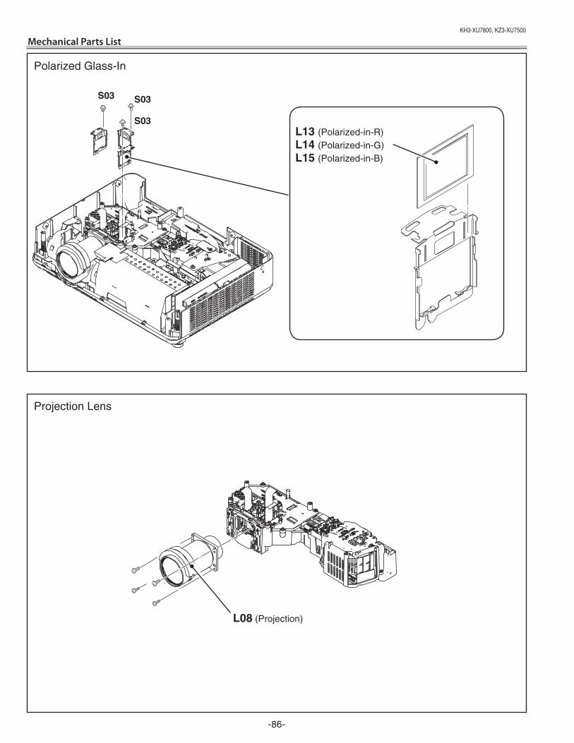
KH3-XU7800,KZ3-XU7500
-86-
Mechanical Parts List
L13 (Polarized-in-R)L14 (Polarized-in-G)L15 (Polarized-in-B)
S03S03
L08 (Projection)
Polarized Glass-In
Projection Lens
S03
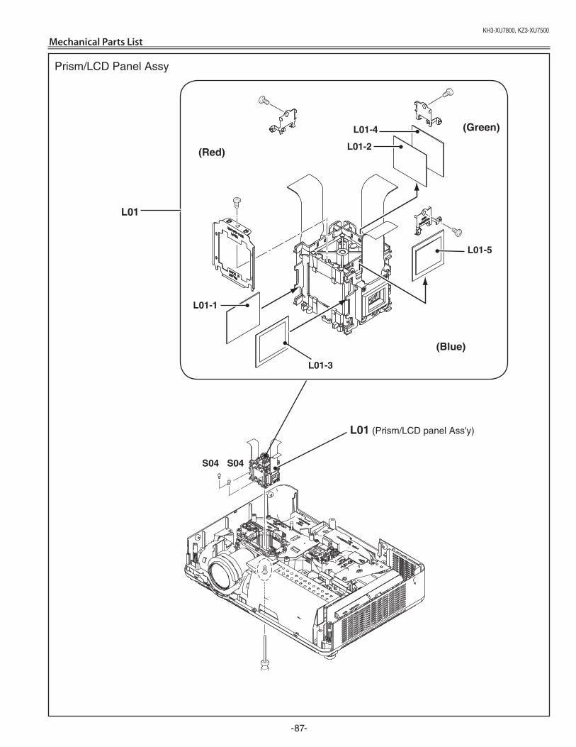
KH3-XU7800,KZ3-XU7500
-87-
Mechanical Parts List
L01 (Prism/LCD panel Ass'y)
L01
Prism/LCD Panel Assy
L01-5
(Blue)
(red)
(Green)
L01-3
L01-1
L01-4
L01-2
S04 S04
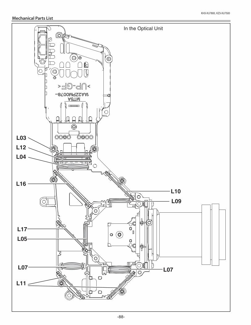
KH3-XU7800,KZ3-XU7500
-88-
Mechanical Parts List
L11
L07
L12
L16
L04
L17
L10
L09
L03
L05
L07
In the Optical Unit
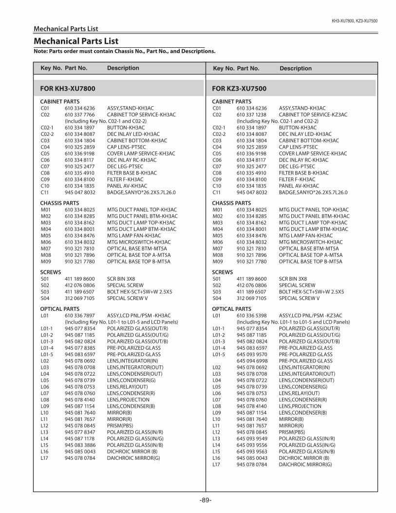
KH3-XU7800,KZ3-XU7500
-89-
Mechanical Parts List
FOR KH3-XU7800
CABINET PARTS C01 610 334 6236 ASSY,STAND-KH3AC C02 610 337 7766 CABINET TOP SERVICE-KH3AC (Including Key No. C02-1 and C02-2) C02-1 610 334 1897 BUTTON-KH3AC C02-2 610 334 8087 DEC INLAY LED-KH3AC C03 610 334 1804 CABINET BOTTOM-KH3AC C04 910 325 2859 CAP LENS-PT5EC C05 610 336 9198 COVER LAMP SERVICE-KH3AC C06 610 334 8117 DEC INLAY RC-KH3AC C07 910 325 2477 DEC LEG-PT5EC C08 610 335 4910 FILTER BASE B-KH3AC C09 610 334 8100 FILTER F-KH3AC C10 610 334 1835 PANEL AV-KH3AC C11 945 047 8032 BADGE,SANYO*26.2X5.7L26.0
CHASSIS PARTS M01 610 334 8025 MTG DUCT PANEL TOP-KH3AC M02 610 334 8285 MTG DUCT PANEL BTM-KH3AC M03 610 334 8162 MTG DUCT LAMP TOP-KH3AC M04 610 334 8001 MTG DUCT LAMP BTM-KH3AC M05 610 334 8476 MTG LAMP FAN-KH3AC M06 610 334 8032 MTG MICROSWITCH-KH3AC M07 910 321 7810 OPTICAL BASE BTM-MT5A M08 910 321 7896 OPTICAL BASE TOP A-MT5A M09 910 321 7780 OPTICAL BASE TOP B-MT5A
SCREWS S01 411 189 8600 SCR BIN 3X8 S02 412 076 0806 SPECIAL SCREW S03 411 189 6507 BOLT HEX-SCT+SW+W 2.5X5 S04 312 069 7105 SPECIAL SCREW V
OPTICAL PARTS L01 610 336 7897 ASSY,LCD PNL/PSM -KH3AC (Including Key No. L01-1 to L01-5 and LCD Panels) L01-1 945 077 8354 POLARIZED GLASS(OUT/R) L01-2 945 087 1185 POLARIZED GLASS(OUT/G) L01-3 945 082 0824 POLARIZED GLASS(OUT/B) L01-4 945 077 8385 PRE-POLARIZED GLASS L01-5 945 083 6597 PRE-POLARIZED GLASS L02 945 078 0692 LENS,INTEGRATOR(IN) L03 945 078 0708 LENS,INTEGRATOR(OUT) L04 945 078 0722 LENS,CONDENSER(OUT) L05 945 078 0739 LENS,CONDENSER(G) L06 945 078 0753 LENS,RELAY(OUT) L07 945 078 0760 LENS,CONDENSER(R) L08 945 078 4140 LENS,PROJECTION L09 945 087 1154 LENS,CONDENSER(B) L10 945 081 7640 MIRROR(B) L11 945 081 7657 MIRROR(R) L12 945 078 0845 PRISM(PBS) L13 945 077 8347 POLARIZED GLASS(IN/R) L14 945 087 1178 POLARIZED GLASS(IN/G) L15 945 083 3886 POLARIZED GLASS(IN/B) L16 945 085 0043 DICHROIC MIRROR (B) L17 945 078 0784 DAICHROIC MIRROR(G)
FOR KZ3-XU7500
CABINET PARTS C01 610 334 6236 ASSY,STAND-KH3AC C02 610 337 1238 CABINET TOP SERVICE-KZ3AC (Including Key No. C02-1 and C02-2) C02-1 610 334 1897 BUTTON-KH3AC C02-2 610 334 8087 DEC INLAY LED-KH3AC C03 610 334 1804 CABINET BOTTOM-KH3AC C04 910 325 2859 CAP LENS-PT5EC C05 610 336 9198 COVER LAMP SERVICE-KH3AC C06 610 334 8117 DEC INLAY RC-KH3AC C07 910 325 2477 DEC LEG-PT5EC C08 610 335 4910 FILTER BASE B-KH3AC C09 610 334 8100 FILTER F-KH3AC C10 610 334 1835 PANEL AV-KH3AC C11 945 047 8032 BADGE,SANYO*26.2X5.7L26.0
CHASSIS PARTS M01 610 334 8025 MTG DUCT PANEL TOP-KH3AC M02 610 334 8285 MTG DUCT PANEL BTM-KH3AC M03 610 334 8162 MTG DUCT LAMP TOP-KH3AC M04 610 334 8001 MTG DUCT LAMP BTM-KH3AC M05 610 334 8476 MTG LAMP FAN-KH3AC M06 610 334 8032 MTG MICROSWITCH-KH3AC M07 910 321 7810 OPTICAL BASE BTM-MT5A M08 910 321 7896 OPTICAL BASE TOP A-MT5A M09 910 321 7780 OPTICAL BASE TOP B-MT5A
SCREWS S01 411 189 8600 SCR BIN 3X8 S02 412 076 0806 SPECIAL SCREW S03 411 189 6507 BOLT HEX-SCT+SW+W 2.5X5 S04 312 069 7105 SPECIAL SCREW V
OPTICAL PARTS L01 610 336 5398 ASSY,LCD PNL/PSM -KZ3AC (Including Key No. L01-1 to L01-5 and LCD Panels) L01-1 945 077 8354 POLARIZED GLASS(OUT/R) L01-2 945 087 1185 POLARIZED GLASS(OUT/G) L01-3 945 082 0824 POLARIZED GLASS(OUT/B) L01-4 945 083 6597 PRE-POLARIZED GLASS L01-5 645 093 9570 PRE-POLARIZED GLASS 645 094 6998 PRE-POLARIZED GLASS L02 945 078 0692 LENS,INTEGRATOR(IN) L03 945 078 0708 LENS,INTEGRATOR(OUT) L04 945 078 0722 LENS,CONDENSER(OUT) L05 945 078 0739 LENS,CONDENSER(G) L06 945 078 0753 LENS,RELAY(OUT) L07 945 078 0760 LENS,CONDENSER(R) L08 945 078 4140 LENS,PROJECTION L09 945 087 1154 LENS,CONDENSER(B) L10 945 081 7640 MIRROR(B) L11 945 081 7657 MIRROR(R) L12 945 078 0845 PRISM(PBS) L13 645 093 9549 POLARIZED GLASS(IN/R) L14 645 093 9556 POLARIZED GLASS(IN/G) L15 645 093 9563 POLARIZED GLASS(IN/B) L16 945 085 0043 DICHROIC MIRROR (B) L17 945 078 0784 DAICHROIC MIRROR(G)
Key No. Part No. description Key No. Part No. description
Mechanical Parts ListNote: Parts order must contain Chassis No., Part No., and Descriptions.

(KH3AC) Aug. �007 DC 350 Printed in Japan SANYo electric co., Ltd.
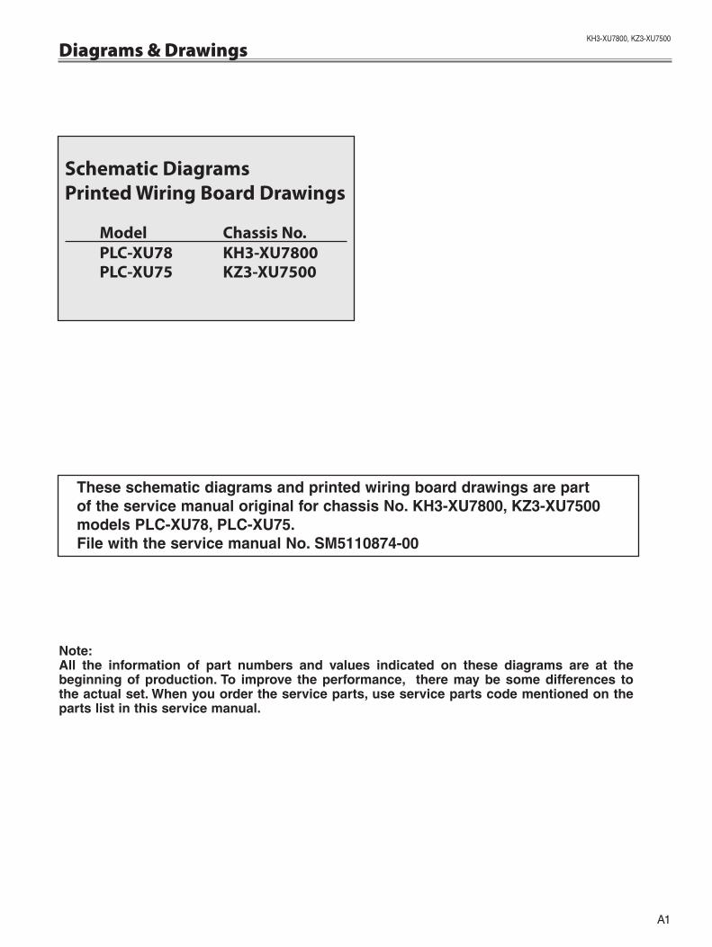
A1
KH3-XU7800,KZ3-XU7500
Schematic DiagramsPrinted Wiring Board Drawings
Model Chassis No. PLC-XU78 KH3-XU7800 PLC-XU75 KZ3-XU7500
Diagrams & Drawings
these schematic diagrams and printed wiring board drawings are part of the service manual original for chassis No. KH3-Xu7800, KZ3-Xu7500 models PLc-Xu78, PLc-Xu75.File with the service manual No. SM5110874-00
Note:All the information of part numbers and values indicated on these diagrams are at the beginning of production. to improve the performance, there may be some differences to the actual set. When you order the service parts, use service parts code mentioned on the parts list in this service manual.
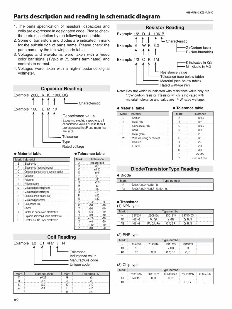
KH3-XU7800,KZ3-XU7500
A�
Parts description and reading in schematic diagram1. The parts specification of resistors, capacitors and
coils are expressed in designated code. Please check the parts description by the following code table.
�. Some of transistors and diodes are indicated in mark for the substitution of parts name. Please check the parts name by the following code table.
3. Voltages and waveforms were taken with a video color bar signal (1Vp-p at 75 ohms terminated) and controls to normal.
4. Voltages were taken with a high-impedance digital voltmeter.
Example L� C1 4R7 K N
Tolerance Inductance value Manufacture code Unique code
coil reading
Note: Resistor which is indicated with resistance value only are 1/6W carbon resistor. Resistor which is indicated with material, tolerance and value are 1/4W rated wattage.
● tolerance table● Material table
● Material table ● tolerance table
● diode
● transistor (1) NPN type
diode/transistor type reading
(�) PNP type
(3) Chip type
Example �000 K K 1000 BG
Example 160 E M 10
Capacitance valueExceptingelectriccapacitors,allcapacitancevaluesoflessthan1areexpressedinµFandmorethan1areinpF.
capacitor reading
Characteristic
Tolerance
TypeRated voltage
Mark MaterialE ElectrolyticP Electrolytic(non-polarized)C Ceramic(temperaturecompensation)K CeramicF PolyesterN PolypropyleneM MetalizedpolypropyleneH MetalizedpolypromylarB Ceramic(semiconductor)G MetalizedpolyestelY CompositefilmS StyrolT TantalumoxidesolidelectrolyticU OrganicsemiconductiveelectrolyteD Electricdoublelayerelectrolytic
Mark ToleranceA notspecifiedB ±0.1C ±0.25D ±0.5F ±1G ±2E ±2.5H ±3J ±5K ±10M ±20N ±30P +100 -0Q +30 -10T +50 -10U +75 -10V +20 -10W +100 -10X +40 -20Y +150 -10Z +80 -20
Mark Tolerance (nH) Mark Tolerance (%)C ±0.25 G ±2D ±0.5 J ±5S ±0.3 K ±10A ±0.2 L ±15
M ±20
Mark MaterialD CarbonN MetalfilmS OxidemetalfilmC SolidG MetalglazeW WirewoundingorcementH CeramicF Fusible
Mark ToleranceA ±0.05B ±0.1C ±0.25D ±0.5F ±1G ±2J ±5K ±10M ±20P +5-15Z usedin0ohm
Mark Type numberR 1S2076A,1S2473,1N4148
AA 1S2076A,1S2473,1SS133,1N4148
Mark Type number-- 2SC536 2SC945A 2SC1815 2SC1740S
AD NF,NG PA,QA Y,GR Q,R,SAE NF,NG PA,QA,RA O,Y,GR Q,R,S
Mark Type number-- 2SA608 2SA564A 2SA1015 2SA933S
AB NF R Y,GR RAC NF Q,R O,Y,GR Q,R
Mark Type number-- 2SA1179N 2SA1037K 2SA1037AK 2SC2812/N 2SC2412KAJ M6,M7 R,S R,SAH L6,L7 R,S
Example 1/� D J 10K B
Example 6 W K 8.�
Example 1/� C K 1M
resistor reading
Characteristic
Z (Carbon fuse)B (Non-burnable)
Resistance valueTolerance (see below table)Material (see below table)Rated wattage (W)
K indicates in KWM indicate in MW
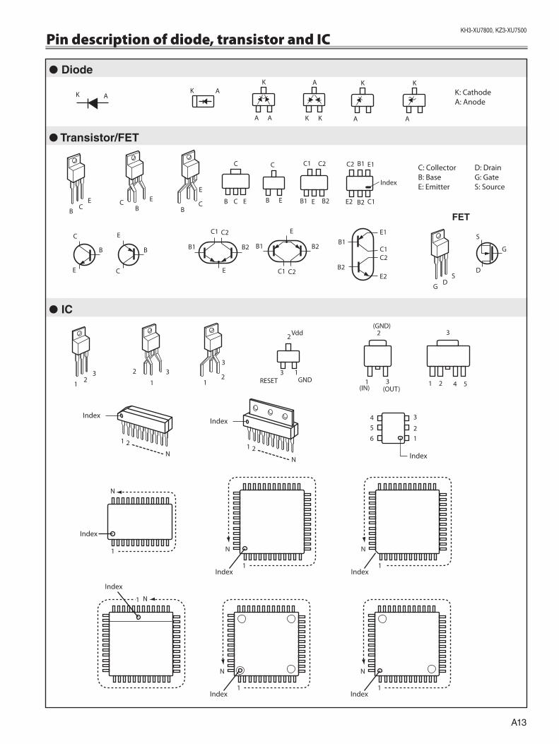
A13
KH3-XU7800,KZ3-XU7500
Pin description of diode, transistor and IC
● diode
● transistor/Fet
● Ic
Fet
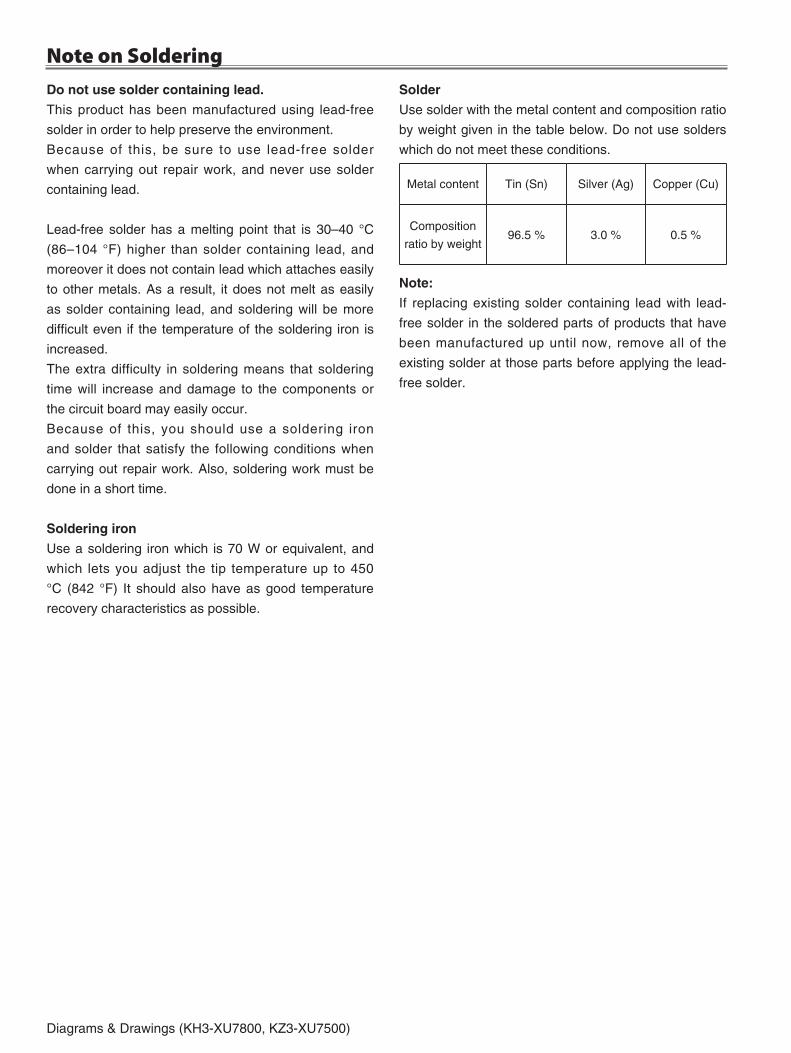
A14Diagrams & Drawings (KH3-XU7800, KZ3-XU7500)
do not use solder containing lead.
This product has been manufactured using lead-free
solder in order to help preserve the environment.
Because of this, be sure to use lead-free solder
when carrying out repair work, and never use solder
containing lead.
Lead-free solder has a melting point that is 30–40 °C
(86–104 °F) higher than solder containing lead, and
moreover it does not contain lead which attaches easily
to other metals. As a result, it does not melt as easily
as solder containing lead, and soldering will be more
difficult even if the temperature of the soldering iron is
increased.
The extra difficulty in soldering means that soldering
time will increase and damage to the components or
the circuit board may easily occur.
Because of this, you should use a soldering iron
and solder that satisfy the following conditions when
carrying out repair work. Also, soldering work must be
done in a short time.
Soldering iron
Use a soldering iron which is 70 W or equivalent, and
which lets you adjust the tip temperature up to 450
°C (84� °F) It should also have as good temperature
recovery characteristics as possible.
Solder
Use solder with the metal content and composition ratio
by weight given in the table below. Do not use solders
which do not meet these conditions.
Metal content Tin (Sn) Silver (Ag) Copper (Cu)
Composition
ratio by weight96.5 % 3.0 % 0.5 %
Note:
If replacing existing solder containing lead with lead-
free solder in the soldered parts of products that have
been manufactured up until now, remove all of the
existing solder at those parts before applying the lead-
free solder.
Note on Soldering
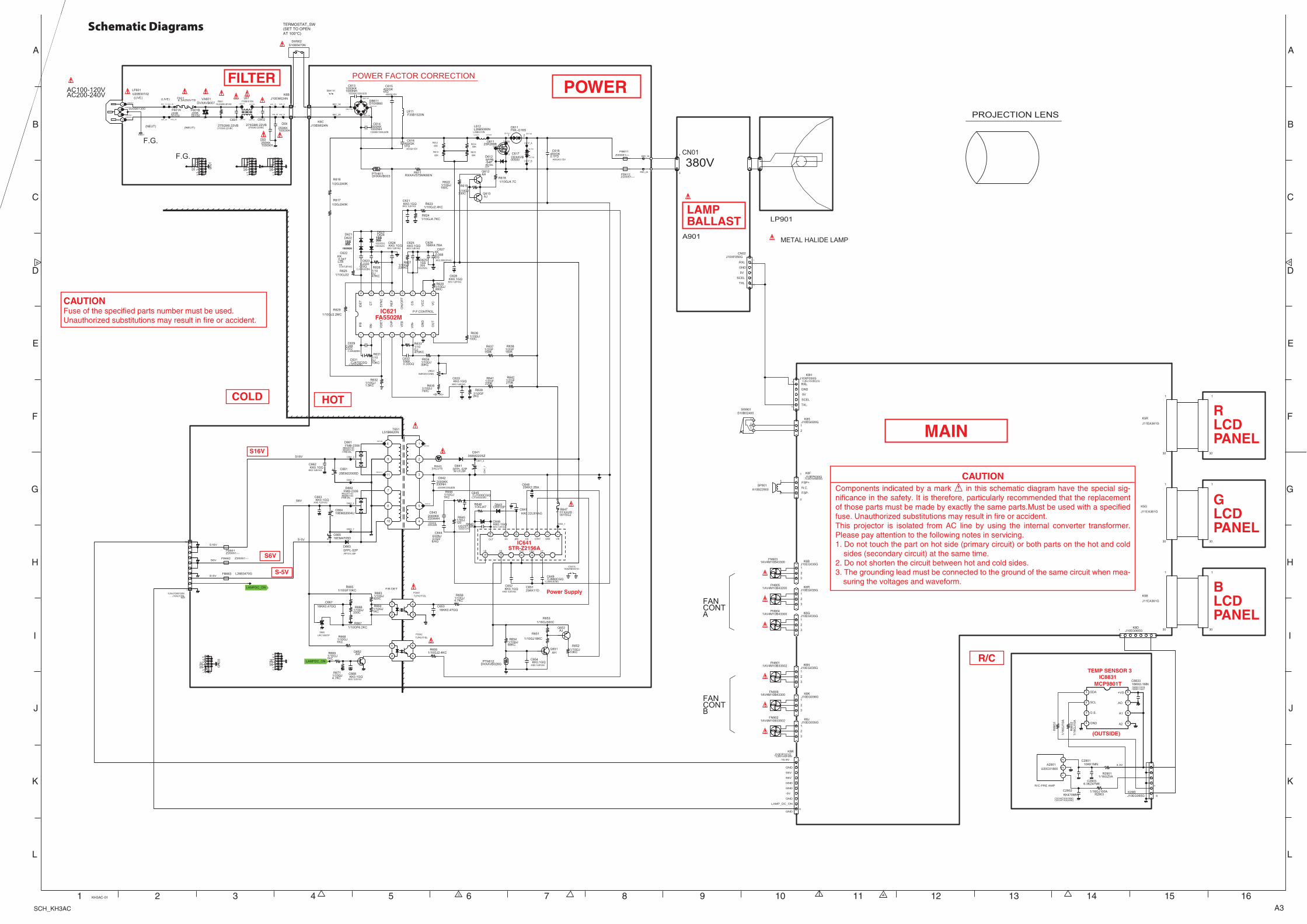
A3SCH_KH3AC
FILTER
LAMPBALLAST
MAIN
COLD
POWER
R/C
HOT
IC621FA5502M
S6V
S-5V
S16V
Power Supply
RLCDPANEL
GLCDPANEL
BLCDPANEL
IC641STR-Z2156A
MCP9801TIC8831
TEMP SENSOR 3
(OUTSIDE)
POWER FACTOR CORRECTION
J10EG036GK6K
11
2
3
J10EG035GK6J
11
2
33
J10EG035GK6B
11
2
33
1AV4M10B43300FN906
1AV4M10B43300FN903
1AV4M10B33502FN902
1AV4M10B33502FN901
J10EG035GK6N
11
2
3
J10EP030GK8F
:1LB4J10WB030G
1
1
2
3
3
A10B22900SP901
1
2
J10EG020GK8S
11
2
J10XF050GCN02
1
5
J10XF050GK8H
:1LB4J10WB020G1
5
J10EG065GK8D
1
J10EP101GK8R
:1LB4J10XB100N
11
2
3
4
5
6
7
8
9
1010
1AV4M10B43300FN904
J10EG035GK6G
11
2
3
1AV4M10B43200FN905
J10EG035GK6R
11
2
3
S10B5470NSW902
1 2
SCB2
12
34
56
78
910 1
1 121
314
SCB1
12
34
56
78
910 1
1 121
314
GND1
SCB3
12
34
56
78
910 1
1 121
314
J20B00100
F601B
K6A_1B
275GM0.22VB
C602
:275GK0.22VBC
K6A_1A
LF601H3
250KK1000XH
C603
J20B00100
F601A
275GM0.22VB
C601
:275GK0.22VBC
K6B_2B
LF601H1
250KK1000XH
C604
DVXAVB007VA601
1
2
U20B61300
1
2
3
4
L601H2
K6A_2A
J10EM024NK6B
1
2K6A_2B
GND1
K6B_1B
LF601H4
F35B1010NL601
1 234
K6B_2A
L601H4
LF601H2
L601H1
L601H3
K6B_1A1SJ240KLBYASR601
J10EG065GK29D
1
4
6
1/1
6G
J10
AR
8832
11 SDA
2 SCL
3 O.S.
4 GND 5A2
6A1
7AO
8+VS
6.3KZ47MEC2903
1/16GJ100AR2903
16KK0.1MNC8833
:16KK0.1AYH:16KK0.1AXY
1/16GZ0AR2901
10KK1MNC2901
U20C01800A2901
12
31
/16
GJ1
0A
R88
31
KK470MNC2902
:CK1H471KAYHNG:CK1H471KAXHNG
1/10GJ820C
R663
AHQ651
1/10GJ4.7KCR624
L51B6620NT651
2
3
5
6
7
8
10
9
11
4
1
400GK1FD
C615
:400GK1DV
CJ680CGQC649
:CJ680LBZBG
Z20051---FB661
SCB1
12
34
56
78
910 1
1 121
314
AJQ613
C64135EM220SZC661_2
1/10GJ180C
R622
AJQ652
1/10GJ390C
R628
J10AU105NK6R
:1LB4J10XB100N
1 1
2
3
4
5
6
7
8
9
1010
1/10GJ10KC
R631
10EM22004UC664
16KK0.47GQC667
KK0.047LZB
C622
:KK0.047LBYAG
1/10GJ330C
R619
25KK11DC651
1000KK1000NH
C613
:1000KK1000LBZB
1/10GJ470KC
R633
1SS355
D622
:1SS352G
1/10GJ1KC
R668
1/10GJ4.7CR618
Q611HG
UPC1093TPD665
D611H1
KK0.1GQC621
:KK0.1LBYAG
KK0.068GQ
C627
:KK0.068LBYAG
KK0.1GQC668
:KK0.1LBYAG
1/10GF2KC
R639
10KK0.33GQ
C632
1/2GF220K
R641
SCB4
12
34
56
78
910 1
1 121
314
K6C_2A
CEXAVB00500
C617
1/10GJ10KC
R652
KK0.1GQC628
:KK0.1LBYAG
T651H5
1/2GJ240KR616
KK0.1GQC663
:KK0.1LBYAG
C617H2
1SS355
D621
:1SS352G
1000KK1000NH
C614
:1000KK1000LBZB
2SK2698Q611
1G
2D
3S
DB611H1 2
C661_1
DB611H3
CJ330CGQ
C623
:CJ330LBZBG
2000KK330NH
C642
:2000KK330LBZB
C662_1
FFXAVB001SGJ
R647
12
KK0.1GQC662
:KK0.1LBYAG
1/3GJ120
R645
1/10GJ18KC
R651
AHQ662
DHXAVB003PTH611
16KK4.7BAC626
1/10GJ30KC
R634
1SS355
D624
:1SS352G
C617H1
Z20051---FB611
TLP421F-BLPC641
1
2 3
4
LAMPDC_ON
1/10GJ100C
R636
Z20051---FB662
L612H2
1/2GF270K
R642
CRF03PD643
DB611H4
K6D_2A
1/10GJ220KC
R627
KK0.1GQC625
:KK0.1LBYAG
1/2GF150K
R638
T651H6
1/10GJ47KC
R626
1/2GJ240KR617
SFPB-54P
D612
;RB160L-40P
1/10GJ68KC
R654
1/10GJ1.5KC
R632
Z20051---FB612
C617_B
L26B3470GFB663
C641_2
1
VIN
3
GND4
CT
5CONT
6
CSS
7
CD
8
VCC
9
DRI
11
OC
12
OS
14
OUT
15
VB
K6D_1A
UDZS12BGD642
:02DZ12YG
R61468K
1/10GJ1KC
R664
D611H2
630NJ0.022EAQ
C644
LAMPDC_ON
Q611HD
1/10GJ1KC
R669 1/10GJ2.4KCR655
KK0.1GQC624
:KK0.1LBYAG
1/10GJ1KC
R644
1/10GJ4.7KC
R656
CJ470CGQC631
:CJ470LBZBG
1/3GJ47R646
450GK0.1FD
C618
:450GK0.1DV
FMB-2306D661
:RB225T-60:RB085T-60:FMB-26L
C617_A
L26B5080NL612
:L26B5370N
12
AHQ612
KK0.1GQC633
:KK0.1LBYAG
1/10GJ750C
R635
1SS355
D625
:1SS352G
FMB-2306D662
:RB225T-60:RB085T-60:FMB-26L
KK0.22LBYAGC647
K6C_1A
16EM4705DC665
GN
D3
IC641A1AA2HEA0310--
1 2
F35B1520NL611
CJ1000CGQC645
:CJ1000LBZBG
CJ68CGQ
C629
:CJ68LBZBG
1/10GJ22R625
IC63_1
1/10GJ4.7KC
R671
SFPL-52PD663
;RF101L2SP
1/10GF6.2KCR667
1/10GF10KCR665
KK0.1GQC646
:KK0.1LBYAG
T651H1
3/4JJ15R643
400GK1FD
C616
:400GK1DV
FML-G16SD611
DB611H2
1/16GJ560CR653
R61268K
16KK0.47GQC653
DHXAVB028GPTH612
J10EM024NK6C
1
2
C64
1_1
25EM22005D
C661
25KK2.2BAC648
R61368K
1SS355
D623
:1SS352G
TLP421F-BLPC642
1
2 3
4
1/2GF150K
R637
R61568K
T651H11
1/10GJ2.2MC
R629
2000KK220AHH
C643
:2000KK220LBZB
SFPL-52PD641
:RF101L2SP
B4R3ZA102NNVR621
1
2
3
KK0.1GQC652
:KK0.1LBYAG
D10XB60DB61111
22 33
44
L612H1
1/10GJ330C
R666
1IF
B
2IIN
-
3V
DE
T
4O
VP
5V
FB
6V
IN-
7G
ND
8O
UT
9V
C
10V
CC
11C
S
12O
N/O
FF
13R
EF
14S
YN
C
15C
T
16ID
ET
RXXAV575MKBENR611
1/10GJ2.4KCR623
KK0.1GQC654
:KK0.1LBYAG
Q611HS
C662_2
DB611H1
A901
K5R
J11EA361G
1
30
30
1
30
1
LP901
METAL HALIDE LAMP
K5G
J11EA361G
K5B
J11EA361G
1
30
30
1
1
30
FANCONTB
FANCONTA
PROJECTION LENS
SCEL
GND
RXL
TXL
CN01
380V1
3
RXL
GND
SCEL
TXL
FSP-
N.C.
FSP+
5V
5V
15.5V
S6V
-5V
LAMP_DC_ON
GND
GND
GND
GND
GND
S6V
F.G.
F.G.
(NEUT)
AC100-120V(LIVE)AC200-240V
(NEUT)
U20B30102F6016.3A250VTS(LIVE)
LF601
3.3V
R/C PRE AMP
F/B DET
2
S6V
S-5V
P.F.CONTROL
1
S6V
S-5V
S16V
S16V
<B-1K>
1 2 3 4 5 6 7 8 9 10 11 12 13 14 15 16
A
B
C
D
E
F
G
H
I
J
K
L
A
B
C
D
E
F
G
H
I
J
K
L
KH3AC-01
TERMOSTAT_SW(SET TO OPENAT 100°C)
CO
MN
ON
C
S10B02400SW901
12
3
Schematic Diagrams
cAutIoNComponents indicated by a mark ! in this schematic diagram have the special sig-nificance in the safety. It is therefore, particularly recommended that the replacement of those parts must be made by exactly the same parts.Must be used with a specified fuse. Unauthorized substitutions may result in fire or accident.This projector is isolated from AC line by using the internal converter transformer. Please pay attention to the following notes in servicing.1. Do not touch the part on hot side (primary circuit) or both parts on the hot and cold
sides (secondary circuit) at the same time.�. Do not shorten the circuit between hot and cold sides.3. The grounding lead must be connected to the ground of the same circuit when mea-
suring the voltages and waveform.
cAutIoNFuse of the specified parts number must be used.Unauthorized substitutions may result in fire or accident.
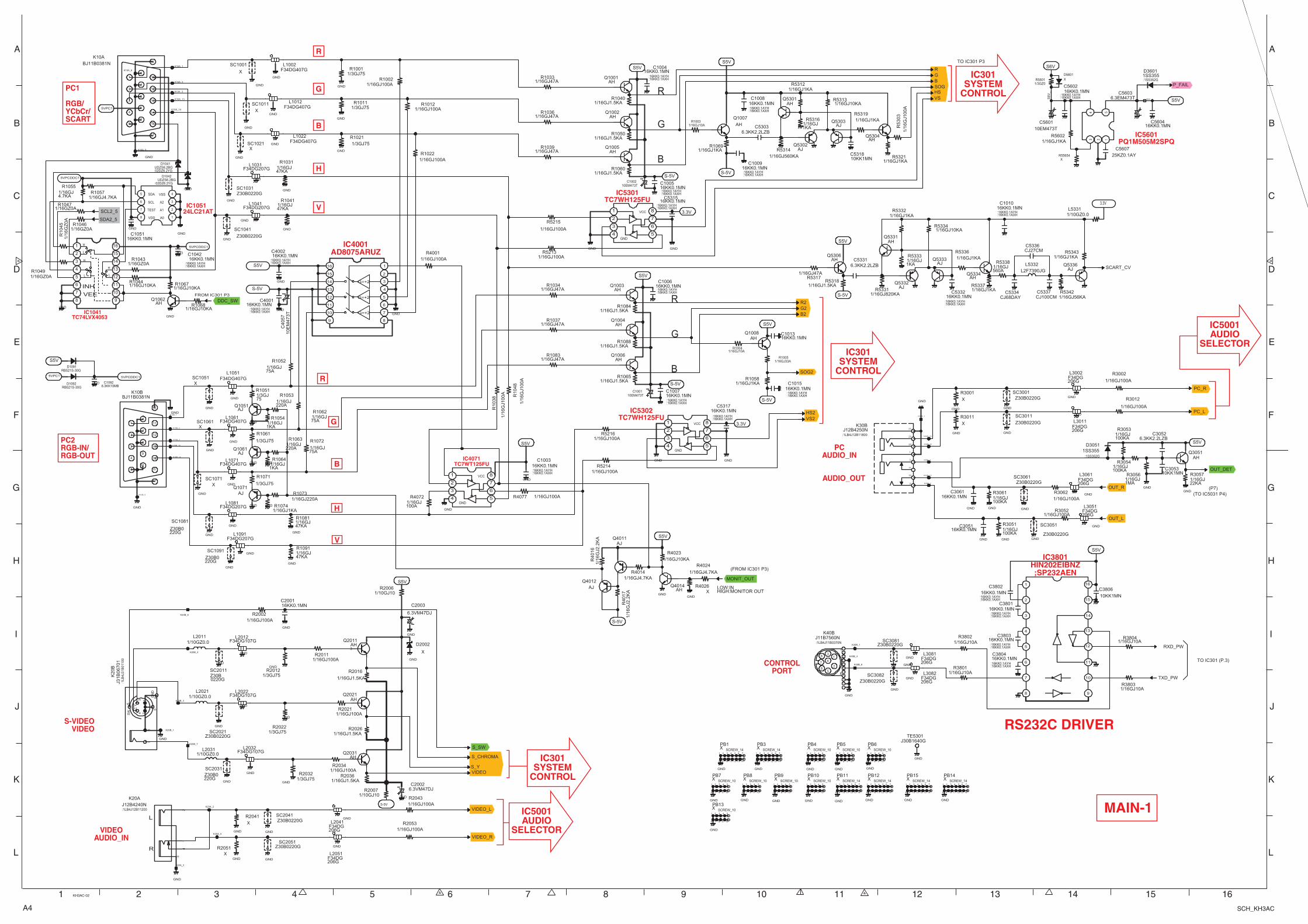
A4 SCH_KH3AC
PC1
RGB/YCbCr/SCART
PC2RGB-IN/RGB-OUT IC4071
TC7WT125FU
IC4001AD8075ARUZ
IC5301TC7WH125FU
R
G
B
H
V
TC74LVX4053IC1041
24LC21ATIC1051
CONTROLPORT
S-VIDEOVIDEO
PCAUDIO_IN
AUDIO_OUT
VIDEOAUDIO_IN
IC5001AUDIO
SELECTOR
IC5001AUDIO
SELECTOR
IC301SYSTEM
CONTROL
R
G
B
H
V
IC5302TC7WH125FU
IC301SYSTEM
CONTROL
IC301SYSTEM
CONTROL
IC5601PQ1M505M2SPQ
IC3801HIN202EIBNZ;SP232AEN
RS232C DRIVER
MAIN-1
1 2 3 4 5 6 7 8 9 10 11 12 13 14 15 16
A
B
C
D
E
F
G
H
I
J
K
L
A
B
C
D
E
F
G
H
I
J
K
L
KH3AC-02
BJ11B0381NK10B
1
3
4
5
6
7
8
9
10
11
12
13
14
15
2
16
17
BJ11B0381NK10A
1
3
4
5
6
7
8
9
10
11
12
13
14
15
2
16
17
10KK1MNC3053
6.3KK2.2LZBC3052
16KK0.1MNC2001
AHQ2021
AHQ2031
AHQ2011
1
2
3
AHQ3051
AHQ4014
OUT_L
OUT_DET
S_SW
MONIT_OUT
LOW:INHIGH:MONITOR OUT
OUT_R
PC_R
PC_L
VIDEO_L
VIDEO_R
VIDEO
S_CHROMA
AJQ1071
AJQ1051
AJQ1061
S5V
S5V
S5V
J30B1640GTE5301
XSC1051
1
2
Z30B0220GSC3061
1
2
XSC1021
1
2
Z30B0220GSC3082
1
2
XSC1061
1
2
Z30B0220GSC2051
1
2
Z30B0220GSC3081
1
2
Z30B0220G
SC2031
1
2
X
SC1001
1
2
Z30B0220G
SC3051
1
2
X
SC10111
2
Z30B0220G
SC2011
1
2
Z30B0220GSC2021
1
2
Z30B0220G
SC3011
1
2
Z30B0220GSC2041
1
2
Z30B0220GSC3001
1
2
Z30B0220G
SC1081
1
2
F34DG107GL2032
1
2
3
F34DG206G
L2041
1
2
3
F34DG207GL1081
1
2
3
F34DG407GL1061
1
2
3
F34DG207GL1091
1
2
3
F34DG107GL2012
1
2
3
F34DG206G
L30821
2
3
F34DG207GL1031
1
2
3
F34DG206G
L3002
1
2
3
F34DG407GL1012
1
2
3
F34DG407GL1022
1
2
3
F34DG407GL1051
1
2
3
F34DG206G
L30811
2
3
F34DG206G
L3051
1
2
3
F34DG206G
L3061
1
2
3
F34DG206G
L2051
1
2
3
F34DG207GL1041
1
2
3
F34DG407GL1071
1
2
3
F34DG407GL1002
1
2
3
F34DG107GL2022
1
2
3
F34DG206G
L3011
1
2
3
S-5V
S5V
6.3VM47DJ
C2003
S5V
1/10GZ0.0L2031
1/10GZ0.0L2021
1/10GZ0.0L2011
J12B4240NK20A
:1LB4J12B11200
12
3
4
J12B4250NK30B
:1LB4J12B1180023
21
3
1
11
10
22
2
SCREW_10XPB6
1 2 3 4 5
6 7 8 9 10
SCREW_10XPB5
1 2 3 4 5
6 7 8 9 10
SCREW_10XPB9
1 2 3 4 5
6 7 8 9 10
SCREW_10XPB7
1 2 3 4 5
6 7 8 9 10
SCREW_10XPB8
1 2 3 4 5
6 7 8 9 10
SCREW_10XPB10
1 2 3 4 5
6 7 8 9 10
SCREW_10XPB13
1 2 3 4 5
6 7 8 9 10
SCREW_10XPB4
1 2 3 4 5
6 7 8 9 10
SCREW_14XPB11
1 2 3 4 5 6 7
8 9 10 11 12 13 14
SCREW_14XPB12
1 2 3 4 5 6 7
8 9 10 11 12 13 14
J11B7560NK40B
:1LB4J11B0370N
11
1
2
2
33
445
56
6
7
7
88
8
9
10
11
H
L
INH
VEE
H
L L
H
1
2
3
4
5
6
7
8 9
10
11
12
13
14
15
16
Z30B0220GSC1031
1
2
Z30B0220G
SC1041
1
2
1A0
2A1
3A2
4VSS5 SDA
6 SCL
7 TEST
8 VDD
5VPCDDC1
16KK0.1MNC1051
5VPCDDC1
AHQ1062 DDC_SW
XSC1071
1
2
Z30B0220G
SC1091
1
2
5VPC1
5VPC1
RB521S-30GD1091
RB521S-30GD1092
6.3KK10MBC1092
5VPCDDC1
S5V
1/16GJ100A
R5215
1/16GJ100A
R3002
1/16GJ22KA
R3057
1/16GJ100AR1022
1/16GJ47KA
R1041
1/16GJ220A
R1063
1/16GJ100AR2002
1/16GJ100KA
R3061
1/16GJ4.7KAR1057
1/3GJ75R1001
1/16GJ100AR4077
1/16GJ10KAR1044
1/16GJ75A
R1052
1/16GJ47KA
R1081
XR4026
1/1
6G
J10
0A
R10
48
1/3GJ75R1021
1/3GJ75R2032
1/16GJ10KAR1068
1/3GJ75R1011
1/3GJ75R2022
R10551/16GJ4.7KA
R10621/16GJ75A
XR2051
1/16GJ100AR3052
1/16GZ0AR1049
1/16GJ100AR2053
R30531/16GJ100KA
R1072
1/16GJ75A
1/1
6G
Z0
AR
1045
1/16GJ47KA
R1031
1/16GJ1KA
R1054
1/16GJ10KAR4023
X
R2041
X
R3001
1/16GJ47KA
R1091
1/10GJ10R2006
R30561/16GJ1MA
1/16GJ100AR3062
1/3GJ75
R1071
1/16GJ100AR1012
1/16GJ100KA
R3054
1/16GZ0AR1043
1/16GJ100AR1002
1/16GJ100AR5213
1/16GJ100AR2034
1/3GJ75
R1051
1/3GJ75
R1061
1/16GZ0AR1046
1/16GJ220A
R1053
1/16GJ4.7KA
R4024
1/16GJ100A
R4072
1/16GJ100KA
R3051
1/16GJ1KAR1074
1/16GJ10KAR1067
X
R3011
1/16GJ100A
R3012
1/16GJ1.5KAR2036
1/16GZ0AR1047
1/16GJ1.5KAR2026
1/16GJ220AR1073
1/16GJ100AR4001
1/16GJ4.7KAR4014
1/16GJ1KA
R1064
1/16GJ100AR2043
1/3GJ75R2012
1/1
6G
J10
0A
R10
38
1/16GJ1.5KA
R2016
K10A_2
K10A_3
K20B_1
K30B_22
K30B_3
K30B_2
K10B_14
K20B_4
K30B_10
K10B_1
K20A_2
K20A_3
K10A_6
K10A_1
K10A_14
K40B_6
K20A_5
K20B_3
K40B_4
K10B_3
K10B_5
K30B_23
K40B_1
K20B_7
K10B_2
K10A_13
K10B_13
K30B_1
K20B_6
K10A_5
3.3V1
2
3
4GND
5
6
7
8VCC
VSHS
S_Y
1/16GJ56KAR5342
AHQ5331
CJ68DAYC5334
1/16GJ1KAR5336
1/16GJ1KAR5332
CJ27CMC5336
L2F7390JGL5332
1/16GJ1KA
R5333
SCART_CV
AHQ5306
1/16GJ560A
R5338
S-5V 1/16GJ820KAR5331
AJQ5336
AJQ5332
AHQ5334
S5V
1/16GJ10KAR5334
1/16GJ1KAR5337
1/16GJ1KAR5343
1/16GJ1.5KAR5318
AJQ5333
1/16GJ47AR5317
S-5V
6.3VM47DJC2002
1/10GJ10R2007
AJQ4011
S-5V
1/1
6G
J2.2
KA
R4
016
1/1
6G
J2.2
KA
R4
017
1
2
3
4GND
5
6
7
8VCC
SDA2_5
SCL2_5
1/16GJ100AR2021
1/16GJ100AR2011
1/16GJ1.5KAR1060
1/16GJ47AR1033
AHQ1001
RG
AH
Q1007
S-5V
1/16GJ1.5KAR1050
AHQ1002
S5V
S-5V
1/16GJ1KAR1069
B
1/16GJ1.5KAR1040
S5V
1/16GJ47AR1036
AHQ1005
1/16GJ47AR1039
G2
1/16GJ47AR1034
S-5V
1/16GJ1.5KAR1088
S5V
AHQ1006
AHQ1004
1/16GJ1.5KAR1065
R2
AHQ1003
1/16GJ1.5KAR1084
B2
1/16GJ47AR1083
1/16GJ47AR1037
1/16GJ100AR5216
1
2
3
4GND
5
6
7
8VCC
1/16GJ100AR5214
VS23.3V
HS2
1/16GJ1KAR1058
S5V
S-5V
AHQ1008
SOG2
TXD_PW
S5V
1/16GJ10AR3803
1/16GJ10AR3801
10KK1MN
C3806
1/16GJ10AR3804
1/16GJ10AR3802
1
2
3
4
5
6
7
8 9
10
11
12
13
14
15
16
RXD_PW
J31
B0
67
01
K20
B
:1LB
4J31
B01
100
12
3Y
4C 5
6S
W
78
9GN
D
S6V
S5V5601_3
P_FAIL
3.3V
SCREW_14XPB15
1 2 3 4 5 6 7
8 9 10 11 12 13 14
SCREW_14XPB14
1 2 3 4 5 6 7
8 9 10 11 12 13 14
X
D2002
10EM473TC1002
10EM473TC1001
10EM473TC5601
6.3EM473TC5603
6.3KK2.2LZBC5331
16KK0.1MNC3061
16KK0.1MNC3051
CJ100CMC5337
1234 5
25KZ0.1AYC5607
1/16GJ1KAR5602
1/1
6G
J10
0A
R53
03
1/16GJ1KAR5312
1/16GJ1KA
R5316
AHQ5301
1/16GJ560KAR5314
SOG
AHQ5304
1/16GJ1KAR5319
10KK1MNC5318
1/16GJ1KAR5321
AJQ5303
AJQ5302
1/16GJ10KAR5313
10
EM
47
3T
C40
57
16KK0.1MNC3803
:16KK0.1AYH:16KK0.1AXH
16KK0.1MNC3802
:16KK0.1AYH:16KK0.1AXH
16KK0.1MNC3801
:16KK0.1AYH:16KK0.1AXH
16KK0.1MNC3804
:16KK0.1AYH:16KK0.1AXH
1SS355D3601
:1SS352G
1SS355D3051
:1SS352G
UDZS6.2BGD1041
:02DZ6.2YG
UDZS6.2BGD1042
:02DZ6.2YG
16KK0.1MNC5602
:16KK0.1AYH:16KK0.1AXH
16KK0.1MNC5604
16KK0.1MNC1005
:16KK0.1AYH:16KK0.1AXH
16KK0.1MNC1009
:16KK0.1AYH:16KK0.1AXH
16KK0.1MNC5317
:16KK0.1AYH:16KK0.1AXH
16KK0.1MNC1013
16KK0.1MNC1008
:16KK0.1AYH:16KK0.1AXH
16KK0.1MNC1004
:16KK0.1AYH:16KK0.1AXH
16KK0.1MNC5315
:16KK0.1AYH:16KK0.1AXH
16KK0.1MNC1007
:16KK0.1AYH:16KK0.1AXH
16KK0.1MNC1006
:16KK0.1AYH:16KK0.1AXH
16KK0.1MNC1010
:16KK0.1AYH:16KK0.1AXH
16KK0.1MNC5332
:16KK0.1AYH:16KK0.1AXH
16KK0.1MNC1015
:16KK0.1AYH:16KK0.1AXH
16KK0.1MNC1003
:16KK0.1AYH:16KK0.1AXH
16KK0.1MNC1042
:16KK0.1AYH:16KK0.1AXH
16KK0.1MNC4001
:16KK0.1AYH:16KK0.1AXH
16KK0.1MNC4002
:16KK0.1AYH:16KK0.1AXH
SCREW_14XPB3
1 2 3 4 5 6 7
8 9 10 11 12 13 14
SCREW_14XPB1
1 2 3 4 5 6 7
8 9 10 11 12 13 14
G=+2
G=+2
G=+2
1
2
3
4
5
6
7
89
10
11
12
13
14
15
16
1/10GZ0.0L5331
1/16GJ33AR1005
1/16GJ10AR1003
1/16GJ10AR1004
6.3KK2.2LZBC5303
AJQ4012
GND
GND
GND
GND
GND
GND
GND
GND
GND
GND
GND
GND
GND
GND
GND
GND
GND
GND
GND
GND
GND
GND
GND
GND
GND
GND
GND
GND
GND
GND
GND
GND
GND
GND
GND
GND
GND
GND
GND
GND
GND
GND
GND
GND
GND
GND
GND
GND
GND
GND
GND
GND
GND
GND
GND
GND
GND
GND
GND
GND
GND
GND
GND
GND
GND
GND
GND
GND
GND
GND
GND
GND
GND
GND
GND
GND
GND
GND
GND
GND
GND
GND
GND
GND
GND
GND
GND
GND
GND
GND
GND
GND
GND
GND
GND
GND
GND
GND
GND
GND
GND
GND
GND
GND
GNDGND
GND GND
GND
GNDGND
XR55654
1/3GZ0R5601 X
D5601
S6V
_
L
R
(TO IC5031 P4)
(FROM IC301 P3)
TO IC301 P3
(P7)
FROM IC301 P3
G
B
R
G
B
R
TO IC301 (P.3)

A5SCH_KH3AC
24LC64T-IIC1371
IC5651FA7703V
TAR5S25IC5681
TC7WBD125IC1303
IC1306AMS1117
FLASH ROM
IC801
PW190-10L
SYSTEM CONTROL
IC301
PST413A300IC841
VS
OPTION RESISTORS
IC401DIGITALGAMMA
*See the part list.
*See the part list.
MAIN-2
P_FAIL
10KK1MNC1871
SD
A1
S1.8V
D_PW
KK470MNC303
KK470MNC314
S3.3VD_PW
S3.3VD_PW
KK470MNC323
RE
AD
Y_
LE
D
S1.8VA_PW
J3
0B
12
70
GT
B
S3.3VA_PW
SCL1
ROMOE
VS
J3
0B
12
70
GT
S_C
J3
0B
12
70
GT
S_Y
10KK1MNC361
LA
MP
_L
ED
S3.3VA_PW
KK470MNC332
VID
EO
S_
CH
RO
MA
S2.5V_PW
DCLK
SDA1 10KK1MNC363
J3
0B
12
70
GT
G
S3.3VA_PW
SCL0
S_Y
SDA0
S2.5V_PW
A[1-23]
TE
MP
_L
ED
S1.8VA_PW
R
KK470MNC329
HS
SO
G
S3.3VD_PW
S1.8VD_PW
G
KK470MN
C311
S3.3VD_PW
PO
WE
R_
LE
D
J3
0B
12
70
GT
SO
G
ROMWE
1
2
3
4 5
6
7
8
S3.3V
D_PW
J3
0B
12
70
GT
VID
EO
KK470MNC307
ON_150VON_50V
BLAST_AC
10KK1MNC362
CJ15CMC1331
:CJ15DAX:CJ15DAY
D[0-15]
J3
0B
12
70
GT
R
KK470MNC336
CHO_RXD
KK470MNC319
CHO_TXD
SC
L1
ON_33V
S3.3VD_PW
S3.3VD_PW
TXD_PW
S1.8VD_PW
A[1-23]
J30
B1
64
0G
TF
L
D[0-15]
ROMOE
J30B1640GT3VFL
S3.3VD_PW
41DQ13
42DQ6
43DQ14
44DQ7
45DQ15/A-1
46VSS
47
48A161 A15
2 A14
3 A13
4 A12
5 A11
6 A10
7 A9
8 A8
9 A19
10 A20
11
12
13 N.C.
14
15
16 A18
17 A17
18 A7
19 A6
20 A5
21 A4
22 A3
23 A2
24 A1 25A0
26
27VSS
28
29DQ0
30DQ8
31DQ1
32DQ9
33DQ2
34DQ10
35DQ3
36DQ11
37VCC
38DQ4
39DQ12
40DQ5
ROMWE
S3.3VD_PW
S3.3VD_PW
DHS
S10B3530GSW841
12
34
S3.3VD_PW
XC851
AD8AC8
AE8
AF9
AE9
IRM_RST
KK1000AYHC844
XD841 S3.3VD_PW
KK0.01AYHC843
S10B3530GSWRST
12
34
S3.3VD_PW
10KK1MNC841
6.3EM473T
C842
S1.8VD_PW
DVS
R/C
DR[0-9]
DG[0-9]
DB[0-9]
KE
Y1
KE
Y2
S6V
S3.3VA_PWL26B3470G
L5662
SCLK_PW
S3.3VD_PW
SDATA_PW
6.3VM47DJC302
TRD
TEXTMCLK
TCS1
TCS0
TWR
TPWM0
PO
W_K
EY
S2.5V_PW
MU
TE
S3.3VD_PW
S3.3VD_PW
SCL2
SDA2
SCL2
SDA2_5
SDA2
1
2 A1
3 B2
4 GND 5A2
6B1
7
8VCC
SCL2_5
SC
AR
T_
CV
J3
0B
12
70
GY
S3.3VD_PW
1LB4V10B0470GX1331
1
GN
D
2
VO
UT
3VD
D
<TOP_VIEW>
280
D7
281
D8
282
D9
283
D10
284
D11
285
D12
30
E26
286
D13
31
F26
287
D14
32
G26
288
D15
33
H26
34
J26
289
D16
35
K26
36
L26
37
M26
38
N26
39
P26
290
D17
291
D18
292
D19
293
D20
294
D21
40
R26
295
D22
41
T26
296
D23
42
U26
297
E23
43
V26
298
F23
44
W26
299
G23
45
Y26
46
AA26
47
AB26
48
AC26
49
AD26
50
AE26
51
AF26
52
AF25
53
AF24
54
AF23
55
AF22
56
AF21
57
AF20
58
AF19
59
AF18
60
AF17
61
AF16
62
AF15
63
AF14
64
AF13
65
AF12
66
AF11
67
AF10
68
AF9
69
AF8
100
B1
101
B2
102
B3
103
B4
104
B5
70
AF7
105
B6
71
AF6
106
B7
72
AF5
107
B8
73
AF4
108
B9
74
AF3
109
B10
75
AF2
76
AF1
77
AE1
78
AD1
79
AC1
110
B11
111
B12
112
B13
113
B14
114
B15
80
AB1
115
B16
81
AA1
116
B17
82
Y1
117
B18
83
W1
118
B19
84
V1
119
B20
85
U1
86
T1
87
R1
88
P1
89
N1
120
B21
121
B22
122
B23
123
B24
124
B25
90
M1
125
C25
91
L1
126
D25
92
K1
127
E25
93
J1
128
F25
94
H1
129
G25
95
G1
96
F1
97
E1
98
D1
99
C1
130
H25
131
J25
132
K25
133
L25
134
M25
135
N25
136
P25
137
R25
138
T25
139
U25
300
H23
140
V25
301
J23
141
W25
302
K23
142
Y25
303
L23
143
AA25
304
M23
144
AB25
305
N23
145
AC25
306
P23
146
AD25
307
R23
147
AE25
308
T23
148
AE24
309
U23
149
AE23
310
V23
311
W23
150
AE22
312
Y23
151
AE21
313
AA23
152
AE20
314
AB23
153
AE19
315
AC23
154
AE18
316
AC22
155
AE17
317
AC21
156
AE16
318
AC20
157
AE15
319
AC19
158
AE14
159
AE13
320
AC18
321
AC17
160
AE12
322
AC16
161
AE11
323
AC15
162
AE10
324
AC14
163
AE9
325
AC13
164
AE8
326
AC12
165
AE7
327
AC11
166
AE6
328
AC10
167
AE5
329
AC9
168
AE4
169
AE3
330
AC8
331
AC7
170
AE2
332
AC6
171
AD2
333
AC5
172
AC2
334
AC4
173
AB2
335
AB4
174
AA2
336
AA4
175
Y2
337 Y4
176
W2
338
W4
177
V2
339
V4
178
U2
179
T2
340
U4
341
T4
180
R2
342
R4
181
P2
343P4
182
N2
344
N4
183
M2
345
M4
184
L2
346
L4
185
K2
347
K4
186
J2
348
J4
187
H2
349
H4
188
G2
189
F2
350
G4
351
F4
190
E2
352
E4
191
D2
353
E5
192
C2
354
E6
193
C3
355
E7
194
C4
356
E8
195
C5
357
E9
196
C6
358
E10
197
C7
359
E11
198
C8
199
C9
360
E12
361
E13
362
E14
363
E15
364
E16
365
E17
366
E18
367
E19
368
E20
369
E21
370
E22
371
F22
372
G22
373
H22
374
J22
375
K22
376
L22
377
M22
378
N22
379
P22
380
R22
381
T22
382
U22
383
V22
384
W22
385
Y22
386AA22
387
AB22
388
AB21
389
AB20
390
AB19
391
AB18
392
AB17
393
AB16
394
AB15
395
AB14
396
AB13
397
AB12
398
AB11
399
AB10
1
A1
2
A2
3
A3
4
A4
5
A5
6
A6
7
A7
8
A8
9
A9
200
C10
201
C11
202
C12
203
C13
204
C14
205
C15
206
C16
207
C17
208
C18
209
C19
210
C20
211
C21
212
C22
213
C23
214
C24
215
D24
216
E24
217
F24
218
G24
219
H24
220
J24
221
K24
222
L24
223
M24
224
N24
225
P24
226
R24
227
T24
228
U24
229
V24
230
W24
231
Y24
232
AA24
233
AB24
234
AC24
235
AD24
236
AD23
237
AD22
238
AD21
239
AD20
400
AB9
401
AB8
240
AD19
402
AB7
241
AD18
403AB6
242
AD17
404
AB5
243
AD16
405
AA5
244
AD15
406
Y5
245
AD14
407
W5
246
AD13
408 V5
247
AD12
409
U5
248
AD11
249AD10
410
T5
411
R5
250
AD9
412
P5
251
AD8
413
N5
252
AD7
414
M5
253
AD6
415
L5
254
AD5
416
K5
255
AD4
417
J5
256
AD3
418
H5
257
AC3
419
G5
258
AB3
259
AA3
420
F5
260
Y3
261
W3
262
V3
263
U3
264
T3
265
R3
10
A10
266 P3
11
A11
267
N3
12
A12
268
M3
13
A13
269
L3
14
A14
15
A15
16
A16
17
A17
18
A18
19
A19
270
K3
271
J3
272
H3
273
G3
274
F3
275
E3
20
A20
276
D3
21
A21
277
D4
22
A22
278
D5
23
A23
279
D6
24
A24
25
A25
26
A26
27
B26
28
C26
29
D26
421
F6
422
F7
423
F8
424
F9
425
F10
426
F11
427
F12
428
F13
429
F14
430
F15
431
F16
432
F17
433
F18
434
F19
435
F20
436
F21
437
G21
438
H21
439
J21
440
K21
441
L21
442
M21
443
N21
444
P21
445
R21
446
T21
447
U21
448
V21
449
W21
450
Y21
451
AA21
452
AA20
453
AA19
454
AA18
455
AA17
456
AA16
457
AA15
458
AA14
459
AA13
460
AA12
461
AA11
462
AA10
463
AA9
464
AA8
465
AA7
466
AA6
467
Y6
468
W6
469
V6
470
U6
471
T6
472
R6
473
P6
474
N6
475
M6
476
L6
477
K6
478
J6
479
H6
480
G6
481
G7
482
G20
483
Y20
484
Y7
485
K10
486
K11
487
K12
488
K13
489
K14
490
K15
491
K16
492
K17
493
L17
494
M17
495
N17
496
P17
497
R17
498
T17
499
U17
500
U16
501
U15
502
U14
503
U13
504
U12
505
U11
506
U10
507
T10
508
R10
509
P10
510
N10
511
M10
512
L10
513
L11
514
L12
515
L13
516
L14
517
L15
518
L16
519
M16
520
N16
521
P16
522
R16
523
T16
524
T15
525
T14
526
T13
527
T12
528
T11
529
R11
530
P11
531
N11
532
M11
533
M12
534
M13
535
M14
536
M15
537
N15
538
P15
539
R15
540
R14
541
R13
542
R12
543
P12
544
N12
545
N13
546
N14
547
P14
548
P13
KK
0.0
1A
YH
C36
4
LA
MP
_D
ET
1/16GJ4.7KAR1309
1/1
6G
J1K
AR
363
R323
1/16GJ10AR372
1/16GJ10KAR801
1/16GZ0AR352
1/16GJ100AR392
1/16GJ1KA
R846
1/16GJ1KAR366
1/16GJ1KAR304
1/16GJ3.3KAR322
1/16GJ10AR348
1/1
6G
Z0
AR
367
1/1
6G
J1K
A
R36
4
1/16GJ10KAR807
1/16GJ1.8KAR809
1/1
6G
J75
AR
382
1/16GZ0AR356
1/16GJ13KC
R361
1/16GZ0AR349
1/16GJ22AR307
1/16GJ4.7KAR852
1/16GJ3.3KAR321
R324
1/16GJ3.3KAR342
1/16GJ1KAR309
R389
1/16GJ1KAR303
1/16GZ0AR312
1/16GJ10KAR808
1/16GJ3.3KAR341
1/16GJ8.2KAR302
1/16GJ10KAR804
R325
1/16GJ4.7KAR1311
1/16GJ3.3KAR343
R391
1/16GJ10KAR300
1/16GJ1KAR311
1/16GJ10A R351
1/16GJ1KAR812
1/16GJ100A
R898
1/16GJ10KAR319
1/16GF23.2KAR306
R320
1/16GZ0AR357
1/16GJ22AR308
1/16GJ100AR340
1/16GZ0AR318
1/16GZ0AR315
1/16GJ10KA
R378
X
R1871
XR301
1/16GJ1MAR1331
1/16GJ3.3KAR339
1/16GZ0AR313
1/16GJ1KAR851
1/16GJ10AR373TAFETST3
S3.3VD_PW
FAN_PWM1FAN_PWM2
S_S
W
SCS_PW
MO
NIT
_O
UT
LO
W:I
NH
IGH
:MO
NIT
OR
OU
T
1/1
6G
J10
KA
R38
0
FAN_CON_B
XR3536
XR3537
SDA2_5
XL3531
FAN_CON_A SCL2_5
FAN_SW1
S5V
1
Gro
und/
Adj
ust
2
Vou
t
3
Vin
4
1/1
6G
J10
A
R35
05
1/1
6G
J10
A
R35
06
TD
AC
1
TD
AC
2
TD
AC
1
TD
AC
2
XIC3531
1 Ao1
2 Ao2
3 Ao3
4 Ao4 5GND
6SDA
7SCL
8VCC
1/16GJ10AR374HS2
J3
0B
12
70
GT
R2
J3
0B
12
70
GT
B2
J3
0B
12
70
G
TG
2
1/16GZ0AR314
1/16GZ0AR316
1/16GJ10AR371 VS2
S1.8VD_PW
S1.8VA_PW
S5V
SO
G2
RXD_PW
1/16GJ3.3KAR3806
S3.3VD_PW
3LN01C-EPQ3801
RB051L-40G
D5611
:CMS16P
GND
KK4700AYH
C5651
1/16GZ0AR5652
GND
1/16GF2.2KAR5671
1/16GJ100KAR5650
GND
GND
KK4700AYH
C5652
1/16GF2.7KAR5672
GND
RB051L-40GD5612
:CMS16P
1R
T
2C
S
3D
T2
4IN
2+
5IN
2-
6F
B2
7G
ND
8O
UT
29
VC
C
10O
UT
1
11S
EL1
12F
B1
13IN
1-
14R
EF
15D
T1
16R
EG
GND
1/16GF4.7KAR5661
GND
GND
1/16GJ100KAR5651
1/1
6G
Z0
AR
5666
1/16GF10KAR5654
GND
L2GE100MGL5611
S3.3VD_PW
S2.5V_PWL2GE100MG
L5612
S6VTXXAVB012G
Q5612
:TTPC6107----P
1
2
3 4
5
6
TXXAVB012G
Q5611
:TTPC6107----P
1
2
3 4
5
6
GND GND
GND
1/16GF2KA
R5662
KK470MNC383
KK470MNC384
KK470MNC385
GND
6.3VM47DJC310
6.3VM47DJC315
6.3VM47DJC320
1/1
6G
J75
AR
1070
16
KK
0.0
68
MN
C10
11
B1
6K
K0
.06
8M
NC
1014
1/1
6G
J75
AR
1077
1/1
6G
J75
AR
1079
G2
16
KK
0.0
68
MN
C10
18
R2
1/1
6G
J75
A
R10
781
6K
K0
.06
8M
N
C10
16
B2
1/1
6G
J75
AR
1075
1/1
6G
J75
AR
1080
16
KK
0.0
68
MN
C10
17
16
KK
0.0
68
MN
C53
16
10
KK
0.4
7M
N
C37
21
/16
GJ7
5A
R35
3
1/1
6G
J10
0A
R35
4
1/1
6G
J10
0A
R35
5
S3.3V
L2
6B
34
70
GL561
0
10EM473TC1353
1/10GZ0.0R5679
6.3EM473TC5664
L26B3470GL5613
L26B3470GL5614
1/10GZ0.0R5680
16KK0.068MNC365
1/1
6G
J75
A
R35
0
25KZ0.1AY
C5680 6.3KK10MBC5684
X
R35
8
1/1
6G
J27
0A
R35
9
1/1
6G
J27
0A
R36
0
1C
ON
TR
OL
2G
ND
3N
OIS
E4
VO
UT
5V
IN
1/16GF1KAR5660
L2FB4R7MGL5661
1
2
J30
B1
64
0G
TE
ICE
1/16GJ1KAR813
16
KK
0.0
68
MN
C53
041
0K
K0
.47
MN
C33
0
10
KK
0.4
7M
NC
373
10
KK
0.4
7M
NC
374
L3BE221PGL307
L3BE221PGL313
L3BE221PGL302
L3BE221PGL314
L3
BE
22
1P
GL3
01
L3BE221PGL308
L3BE221PGL306
L3BE221PGL309
L3BE221PGL304
L3BE221PGL311
L3BE221PGL305
L3BE221PGL312
L3BE221PGL303
DD
C_
SW
LA
MP
_D
C_
ON
1/16GJ100AR347
J3
0B
12
70
GT
HS
J3
0B
12
70
GT
HS
2
J3
0B
12
70
GT
VS
J3
0B
12
70
GT
VS
2
16KK0.1MNC316
:16KK0.1AYH:16KK0.1AXH
16KK0.1MNC5676
:16KK0.1AYH:16KK0.1AXH
16KK0.1MNC1301
16KK0.1MNC342
:16KK0.1AYH:16KK0.1AXH
16KK0.1MNC331
:16KK0.1AYH:16KK0.1AXH
16KK0.1MNC801
:16KK0.1AYH:16KK0.1AXH
16KK0.1MNC381
:16KK0.1AYH:16KK0.1AXH
16KK0.1MNC327
:16KK0.1AYH:16KK0.1AXH
16KK0.1MNC357
:16KK0.1AYH:16KK0.1AXH
16KK0.1MNC1351
:16KK0.1AYH:16KK0.1AXH
16KK0.1MN
C352
:16KK0.1AYH:16KK0.1AXH
16KK0.1MNC318
:16KK0.1AYH:16KK0.1AXH
16KK0.1MNC358
:16KK0.1AYH:16KK0.1AXH
16KK0.1MNC377
:16KK0.1AYH:16KK0.1AXH
16KK0.1MNC312
:16KK0.1AYH:16KK0.1AXH
16
KK
0.1
MN
C37
8
:16K
K0.
1AY
H:1
6KK
0.1A
XH
16KK0.1MNC354
:16KK0.1AYH:16KK0.1AXH
16KK0.1MNC370
:16KK0.1AYH:16KK0.1AXH
16KK0.1MNC333
:16KK0.1AYH:16KK0.1AXH
16KK0.1MNC379
:16KK0.1AYH:16KK0.1AXH
16KK0.1MNC5682
:16KK0.1AYH:16KK0.1AXH
16KK0.1MNC322
:16KK0.1AYH:16KK0.1AXH
16KK0.1MNC308
:16KK0.1AYH:16KK0.1AXH
16KK0.1MNC5655
:16KK0.1AYH:16KK0.1AXH
16KK0.1MNC306
:16KK0.1AYH:16KK0.1AXH
16KK0.1MNC353
:16KK0.1AYH:16KK0.1AXH
16KK0.1MNC321
:16KK0.1AYH:16KK0.1AXH
16
KK
0.1
MN
C38
2
:16K
K0.
1AY
H:1
6KK
0.1A
XH16KK0.1MN
C5661
:16KK0.1AYH:16KK0.1AXH
16KK0.1MNC1371
:16KK0.1AYH:16KK0.1AXH
16KK0.1MNC351
:16KK0.1AYH:16KK0.1AXH
16
KK
0.1
MN
C36
7:1
6KK
0.1A
YH
:16K
K0.
1AX
H
16
KK
0.1
MN
C56
06
:16K
K0.
1AY
H:1
6KK
0.1A
XH
16KK0.1MNC309
:16KK0.1AYH:16KK0.1AXH
16KK0.1MNC5662
:16KK0.1AYH:16KK0.1AXH
16KK0.1MNC334
:16KK0.1AYH:16KK0.1AXH
16KK0.1MN
C346
:16KK0.1AYH:16KK0.1AXH
16
KK
0.1
MN
C34
3
:16K
K0.
1AY
H:1
6KK
0.1A
XH
16KK0.1MNC369
:16KK0.1AYH:16KK0.1AXH
16KK0.1MNC304
:16KK0.1AYH:16KK0.1AXH
16KK0.1MNC347
:16KK0.1AYH:16KK0.1AXH16KK0.1MNC5669
:16KK0.1AYH:16KK0.1AXH
16KK0.1MNC5659
:16KK0.1AYH:16KK0.1AXH
XC3538
16KK0.1MNC317
:16KK0.1AYH:16KK0.1AXH
16KK0.1MNC5605
:16KK0.1AYH:16KK0.1AXH
16KK0.1MN
C344
:16KK0.1AYH:16KK0.1AXH
16KK0.1MNC313
:16KK0.1AYH:16KK0.1AXH
16KK0.1MNC328
:16KK0.1AYH:16KK0.1AXH
16KK0.1MNC326
:16KK0.1AYH:16KK0.1AXH
16KK0.1MN
C341
:16KK0.1AYH:16KK0.1AXH
16KK0.1MNC301
:16KK0.1AYH:16KK0.1AXH
16KK0.1MNC324
:16KK0.1AYH:16KK0.1AXH
16KK0.1MNC380
:16KK0.1AYH:16KK0.1AXH
16KK0.1MNC338
:16KK0.1AYH:16KK0.1AXH
16KK0.1MNC337
:16KK0.1AYH:16KK0.1AXH
16KK0.1MNC335
:16KK0.1AYH:16KK0.1AXH
16
KK
0.1
MN
C34
8
:16K
K0.
1AY
H:1
6KK
0.1A
XH
16KK0.1MNC339
:16KK0.1AYH:16KK0.1AXH
16KK0.1MNC356
16KK0.1MNC355
16
KK
0.1
MN
C36
6
16
KK
0.1
MN
C36
8
16
KK
0.1
MN
C37
1
:16K
K0.
1AY
H:1
6KK
0.1A
XH
1/16GJ100AR383
R384
FA
N_
FE
ED
1
FA
N_
FE
ED
2
XK801
20
2122
2324
25
11
26
22
27
3
28
4
29
56
78
9
30
3132
3334
3536
3738
3940
4142
4344
45
10
46
11
47
12
48
13
4949
14
1516
1718
19
5050
16EM2201XC5671
16EM2201XC5667
CJ15CMC1332
:CJ15DAX:CJ15DAY
16EM2201XC5666
16EM2201XC5681
GND
GND
GND
GND
GND
GND
GND
GND
GND
GND
GND
GND
GND
GND
GND
GND
GND
GND
GND
GND
GND
GND
GND
GND
GND
GND
GND
GND
GND
GND
GND
GND
GND
GND
GND
GND
GND
GND
GND
GND
GND
GND
GND
GND
GND
GND
GND
GND
GND
GND
GND
GND
GND
GND
GND
GND
GND
GND
GND
GND
GNDGND
GND
GND
GND
GND
GND
GND
GND
GND
GND
GND
GND
GND
GND
GND
GND
GND
GND
GND
GND
GNDGND
GND
GND
GNDGND
GND
GND
GND
GND
GND
GND
GN
D
GND
GND
GND
GND GND
1/16GJ100KA
R5653
25KK2.2BA
C5608
D[14]
D[15]D[9]
D[2]
D[4]
D[1]
A[3]
A[5]
A[21]
D[0]
D[7]
D[3]
D[13]
A[8]
A[6]
D[5]
A[2]
D[10]
A[10]
A[7]
A[13]
A[16]
D[6]
D[8]
A[9]
S1.8VD_PW
A[18]
A[14]
D[12]
A[11]
A[20]
A[12]
A[15]
A[4]
A[19]
A[1]
D[11]
D[2]
A[16]
A[19]
A[19]
D[9]
A[17]
D[5]
A[3]
A[9]
D[10]
A[2]
A[11]
D[11]
A[4]
A[13]
A[6]
D[14]
D[7]
A[11]
A[1]
A[16]
D[12]
D[11]
A[18]
A[12]
A[17]
D[8]
D[3]
D[13]
A[14]
A[4]
A[8]
A[13]
D[6]
A[5]
A[19]
A[1]
A[6]
A[20]
D[2]
A[7]
D[4]
D[10]
D[4]
A[2]
D[1]
D[3]
D[5]D[12]
D[6]D[13]
D[7]
A[3]
D[14]
A[15]
A[5]
D[15]
A[7]
A[10]
A[9]
A[18]
D[0]
A[12]
A[20]
D[0]
D[15]
A[14]
D[9]
A[15]
D[1]
A[10]
A[8]
D[8]
A[17]
DR[0]
DR[1]
DR[2]
DR[3]
DR[4]
DR[5]
DR[6]
DR[7]
DR[8]
DR[9]
DG[0]
DG[1]
DG[2]
DG[3]
DG[4]
DG[5]
DG[6]
DG[7]
DG[8]
DG[9]
DB[0]
DB[1]
DB[2]
DB[3]
DB[4]
DB[5]
DB[6]
DB[7]
DB[8]
DB[9]
A[21]
A[23]
A[22]
S3.3VD_PW
(R/C RECEIVER)
rsv
rsv
NC
rsv
rsv
rsv
rsv
NC
NC
rsv
Pr
rsv
rsv
rsv
NC
rsvrsv
NC
NC
rsv
NC
rsv
rsv
NC
rsv
rsv
rsv
NC
rsv
NC
rsv
C2
rsv
rsv
IC801(FLASH)
rsv
Y1
rsv
NC
IN1CLK
rsv
rsv
C1
rsv
rsv
NC
K801(ICE)
NC
Open
rsvrsv
rsvrsv
NC
rsv
rsv
NC
rsv
rsv
rsv
rsv
rsv
NC
rsv
Open
Y
rsv
rsv rsv
NC
NMI
NC
rsv
rsv
V2
rsv rsv
rsv
rsvrsv rsv
rsv
Open
rsv
rsv
NC
rsvrsv
rsv
rsv
Y2
rsv
Open
V1
NC
rsv
27MHZ
NC
FROM IC301
Open
TO DDC
TO IC5001 (AUDIO)TO IC3531 D/A
TO IC7811 P4
TO IC401 P5
FROM P2
BYTE
WE
RESET
WP/ACC
RY/BY
CE
OE
OE1
OE2
1 2 3 4 5 6 7 8 9 10 11 12 13 14 15 16
A
B
C
D
E
F
G
H
I
J
K
L
A
B
C
D
E
F
G
H
I
J
K
L
KH3AC-03
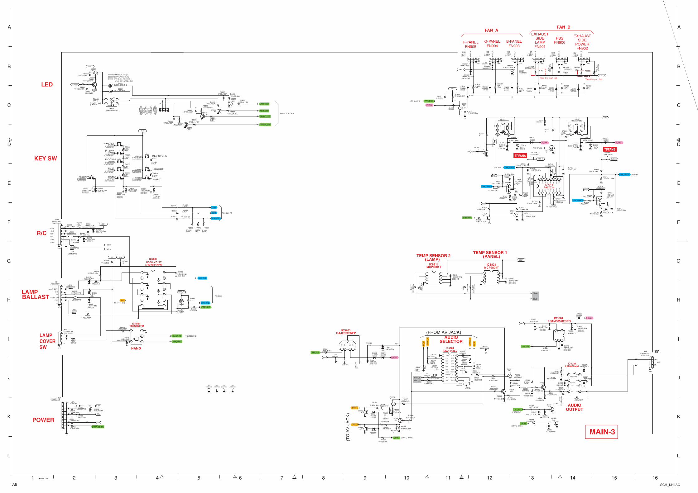
A6 SCH_KH3AC
MAIN-3
PQ1M505M2SPQIC5081
NJW1156AV
AUDIOSELECTOR
AUDIOOUTPUT
IC5001
MCP9801TIC8811
MCP9801TIC8821
TEMP SENSOR 2 (LAMP)
TEMP SENSOR 1 (PANEL)
POWER
KEY SW
R/C
LAMPBALLAST
LAMPCOVERSW
LED
TC7SH00FU
NAND
IC4891
HD74LVC14T;74LVC14APW
IC9883
LM4889MMIC5031
R-PANELFN905
EXHAUSTSIDE
POWERFN902
PBSFN906
EXHAUSTSIDELAMPFN901
G-PANELFN904
FAN_AFAN_B
B-PANELFN903
IC7811FA7703V
TPFANB
TPFANA
IC5461BAJ2CC0WFP
*See the part list. *See the part list.
DLSML-212YT-GD6831
AHQ6841
SML-210LTMGD6832
TEMP_LEDSML-521MUWGD6833
1 2RED
3GREEN
4
POWER_LED
AHQ6844
READY_LEDAH
Q6842
LAMP_LED
ON_50V
P_FAIL
S6V 5081_5
1SS355D3606
:1SS352G
1SS355D5062
:1SS352G
16EM101VC5061
AHQ5032
SCL2_5
16EM101VC5069
AHQ5064
AHQ5063
AHQ5061
SDA2_5
OUT_L
1SS355D5061
:1SS352G
MUTE
J30B1640GTE5001
OUT_R
PC
_L
PC
_R
VID
EO
_L
AHQ5031
VID
EO
_R
16KK10BBC5024
AHQ5062
KK0.01AYHC5041
10KK1MNC5037
AHQ5033
KK0.01AYHC5038
AHQ5036
KK0.01AYHC5039
OUT_DET
MUTE
AHQ5034
K8F_3
J10EP031GK8F
:1LB4J10WD030G
1
SP+
2N.C.
3
SP-
K8F_1
NTS-5VK8R_7
LAMP_DC_ON
25EM1001XC5706
K8R_1
NTS15.5V
K8R_2
NTS6VK8R_3
K8R_9
K8S_3
K8H_4
K8H_5
K8H_3
K8H_0
K8H_1
K8S_1
BLAST_AC
FAN_ERR
AHQ6843
K8D_1
J10EG065GK8D
:1LB4J10WB060G
1
4
K8D_3
R/C
UDZS6.2BGD2891
:02DZ6.2YG
K8D_2
UDZS6.2BGD2892
:02DZ6.2YG
AHQ6862
AJQ6861
10KK1MNC6861
S1.8VD_PW
CHO_RXD
CHO_TXD
S10B3530GSW6802
:1LB4S10B0210G
12
34
SW807_1
POW_KEY
SW806_1
UDZS6.2BGD6803
:02DZ6.2YG
S10B3530GSW6803
:1LB4S10B0210G
12
34
KEY2
S10B3530GSW6801
:1LB4S10B0210G
12
34
SW802_1
UDZS6.2BGD6801
:02DZ6.2YG
SW808_1S10B3530GSW6811
:1LB4S10B0210G
12
34
S10B3530GSW6808
:1LB4S10B0210G
12
34
UDZS6.2BGD6802
:02DZ6.2YG
S10B3530GSW6804
:1LB4S10B0210G
12
34
SW801_1
S10B3530GSW6806
:1LB4S10B0210G
12
34
SW804_1
SW811_1
KEY1
SW803_1
S10B3530GSW6807
:1LB4S10B0210G
12
34
6.3VM47DJ
C4808
L26B3470GL5609
1SHUTDOWN
2BYPASS
3 +IN
4 -IN 5VO1
6VDD
7GND
8VO2
K8D_0
S3.3VD_PW
XQ9881
CJ47DAY
C2892
LAMP_DET
Q7802
X
GND
1/16GJ100A
R5031
1/1
6G
J10
AR
8822
1/16GJ1KAR5037
1/16GJ1KA
R5063
1/16GJ10KA
R6803
X
R5071
1/16GJ3.3KA
R6809
XR9881
1/16GJ3.3KA
R5036
1/16GJ10KA
R6813
1/16GJ1KA
R5061
1/16GJ10KAR5046
1/16GJ1KAR5041
1/16GJ3.3KA
R6801
1/1
6G
J10
A
R88
21
1/16GJ4.7KAR6846
1/16GJ330AR6849
1/16GJ1KA
R5067
XR5068
1/16GJ1KAR6822
1/16GJ180AR4863
1/16GJ3.3KAR4834
1/16GJ22A
R2890
1/16GJ3.9KA
R6808
1/16GJ3.3KAR5066
1/16GJ18KAR5039
1/1
6G
J10
AR
8811
1/16GJ1KAR5048
1/16GJ180AR6843
1/16GJ4.7KAR6859
1/16GJ10KAR5051
1/16GJ1KAR5034
1/16GJ10KAR6862
1/16GJ10KA
R6823
1/16GJ2.7KAR5047
1/16GJ180AR6853
1/10GZ0.0R5001
1/10GZ0.0R4861
1/16GJ100AR2892
1/16GJ1KA
R5069
1/16GJ3.3KAR6812
1/16GJ180AR6857
1/16GJ1KAR5082
1/16GJ10AR5003
1/16GJ180AR6858
1/16GJ15KA
R6806
1/16GJ3.3KAR6804
1/16GJ100A
R5032
1/16GJ4.7KAR6861
1/16GJ3.3KAR5033
XR7804
1/16GJ330AR6848
1/1
6G
J10
AR
8812
1/16GJ4.7KAR6854
1/16GZ0AR9883
1/16GJ180AR4862
1/16GJ1KAR5042
1/16GJ10AR5002
R50441/16GJ10KA
1/16GJ6.8KA
R6807
1/16GJ1KA
R5064
1/16GJ4.7KA
R6851
1/16GJ56KAR6863
R68411/16GJ180A
1/16GJ3.3KA
R5062
10KK1MNC5033
S16V
FAN_PWM1
1/1
6G
J15
KA
R50
52
1/16GJ10KAR5053
K6L_
2
1SS355D3627
:1SS352G
FAN_ERR
K6L_3
1/16GJ10KA
R3624
1SS355D3622
:1SS352G
1/16GJ10KA
R3621
K8N_3
K6
M_1
1/16GJ10KA
R3626
R5622
FNER
1/16GJ10KA
R3627
1SS355D3624
:1SS352G
1SS355D3626
:1SS352G
K8N
_2
16EM101VC5025
:16EM10KE
16
EM
10
1V
C50
28
K6K
_1
1SS355D3621
:1SS352G
Q3601_1
K6J_
2
1/16GJ10KA
R3623
FAN_A
FAN_B
NTD5611
K6
M_2
P_FAIL
1SS355D3617
1/16GJ10KAR3602
16
EM
10
1V
C50
27
1/16GJ3.3KAR3601
K6L_
1 K6M_3
K8P
_2
K8N
_1
AHQ3601
K8P_3
K6J_
1
1/16GJ10KA
R3622
16EM101VC5026
K6J_3
1SS355D3623
:1SS352G
K8P
_1
K6K
_2 K6K_3
GND
1/16GJ1KAR7831
1/16GJ1KAR7881
GNDGND
1/16GJ1MAR7813
RSQ025P03GQ7812
1
2
3 4
5
6
GND
GND
1/16GF27KAR7821
1/16GF2.2KAR7824
1R
T
2C
S
3D
T2
4IN
2+
5IN
2-
6F
B2
7G
ND
8O
UT
29
VC
C
10O
UT
1
11S
EL1
12F
B1
13IN
1-
14R
EF
15D
T1
16R
EG
GND
1SS355D3614
:1SS352G
RSQ025P03GQ7862
1
2
3 4
5
6
GND
FAN_B
1/16GJ1KAR7879
GND
RB051L-40G
D7812
:CMS16P
FAN_A
GND
P_FAIL
1/16GJ100KAR7819
1/16GF10KAR7818
GND
1/16GJ1KAR7829
1/16GJ10A
R7866
1/16GJ3.3KA
R7833
1SS355D3613
:1SS352G
1/16GJ10KAR7878
FAN_CON_B
1/16GF27KAR7871
GND
RB051L-40GD7862
:CMS16P
1/16GJ4.7KA
R7832
S16V
1/16GJ100KAR7869
J30B1640GTPFANA
S16V
S16V
S16V
GND
FAN_SW1
1/16GJ4.7KAR7882
1/16GJ10KA
R7828
1/16GJ10KAR7803
FAN_CON_A
GND
IMZ1AGQ7864
:THN1B01F-Y--P
KK4700AYH
C7868
1/16GJ30KAR7834
J30B1640GTPFANB
GND
GND
GND
P_FAIL
1/16GJ30KAR7884
1/1
6G
J10
A
R78
16
1/16GJ3.3KAR7883
KK 4700A
YH
C78
18
IMZ1AGQ7813
:THN1B01F-Y--P
XR7814
Q7803X
GND
FAN_PWM2
1SS355D3611
:1SS352G
1/16GJ1KAR5641
NT12V
P_FAIL
S3.3V
SCL0
SDA0
AHQ7811
AHQ7801
1/16GJ4.7KAR7805
SCL0
SDA0
S16V
ON_50V
3.3V
1/10GZ0.0R2005
XR2004
1/16GZ0AR9882
1
2
3
4
5
6
7 8
9
10
11
12
13
14
16KK4.7BAC5011
16KK4.7BAC5012
16KK4.7BAC5013
3.3V
1/16GJ100KA
R5007
1/16GJ100KA
R5004
1/16GJ100KA
R5006
1/16GJ100KA
R5005
1
2
3
4 5
6
7
8 1
2
3
4 5
6
7
8
1
2
34
5
25EM1001XC7816
GND
1 GND
2 R1IN
3 R2IN
4 R3IN
5 R4IN
6 R5IN
7 ROUT
8 VSSOUT
9 SCL
10 SDA 11VDDOUT
12VREFOUT
13V+
14VREFIN
15LOUT
16L5IN
17L4IN
18L3IN
19L2IN
20L1IN
GND
1SS355D3602
:1SS352G
J10AU105NK8R
:1LB4J10XB100N
11
2
3
4
5
6
7
8
9
1010
S3.3V
S3.3V
S3.3V
L2GE100MG
L7861
L2GE100MG
L7811
16EM2201X
C781316EM2201X
C7863
25KK2.2BA
C7811
10EM473T
C5003
6.3EM473TC5083
16EM2201XC5087
16KK0.47GQC5032
25KK11DC5001
25KK11DC5004
25KK11DC5002
25KK11DC5009
25KK11D
C5014
16EM101VC5644
25EM1001X
C5006
1234 5
1
CT
L
2
Vcc
4O
UT
5
N.C
.
6
J10EG025GK8S
:1LB4J10WB020G1
2
J10EG035G
K6R
1
FA
N_A
2 3
J10EG035G
K6G
1
FA
N_A
2 3
J10EG036G
K6N
1
FA
N_A
2 3
J10EG035G
K6B
1
FA
N_A
2 3
J10EG035G
K6J
1
FA
N_B
2 3
J10EG035G
K6K
1
FA
N_B
2 3
L3BE221PGFB3624
L3BE221PGFB3622
L3BE221PGFB3627
L3BE221PGFB3623
L3BE221PG
FB3621L3BE221PGFB3626
1/16GJ10KA
R5040
25KK11DC5031
1/16GJ3.9KA
R6811S10B3530GSW6810
:1LB4S10B0210G
12
34
L26B3470GL5606
1
2
L26B3470GL5608
1
2
L26B3470GL5701
1
2
L26B3470GL5702
1
2
1/16GJ100AR5704
S6V
S-5V
L26B0870G
L2894
L26B0870G
L4814
L26B0870G
L4811
L26B0870GL2892
L26B0870GL2893
J10XF050GK8H
1
5
L3BE221PG
L4812
1
2
L3BE221PGL2891
1
2
UD
ZS
6.2
BG
D68
41
:02D
Z6.
2YG
UD
ZS
6.2
BG
D68
43
:02D
Z6.
2YG
UD
ZS
6.2
BG
D68
42
:02D
Z6.
2YG
UD
ZS
6.2
BG
D68
44
:02D
Z6.
2YG
UDZS6.2BGD4813
:02DZ6.2YG
UDZS6.2BGD4812
:02DZ6.2YG
L26B0870GL4809
L26B0870G
L4810
16KK0.1MN
C9882
:16KK0.1AYH:16KK0.1AXH
16KK0.1MNC2891
:16KK0.1AYH:16KK0.1AXH
16KK0.1MNC6802
:16KK0.1AYH:16KK0.1AXH
16KK0.1MNC5008
:16KK0.1AYH:16KK0.1AXH
16KK0.1MNC4891
:16KK0.1AYH:16KK0.1AXH
16KK0.1MNC6803
:16KK0.1AYH:16KK0.1AXH
16KK0.1MNC6801
:16KK0.1AYH:16KK0.1AXH
25KZ0.1AYC5007
16KK0.1MNC8823
:16KK0.1AYH:16KK0.1AXH
16KK0.1MNC8813
:16KK0.1AYH:16KK0.1AXH
16
KK
0.1
MN
C78
17
:16K
K0.
1AY
H:1
6KK
0.1A
XH
16KK0.1MNC5082
:16KK0.1AYH:16KK0.1AXH
16KK0.1MNC5084
:16KK0.1AYH:16KK0.1AXH
16KK0.1MNC5081
:16KK0.1AYH:16KK0.1AXH
25KZ0.1AYC7812FAN_FEED1
FAN_FEED2
1/16GF2.2KAR7874
S3.3V
J30B2130GTP1
J30B2130GTP2
J30B2130GTP3
J30B2130GTP4
1/16GJ10KAR3603
R5623
0R5624
GND
GND
GND GNDGND GND
GND
GND
GND
GND
GND
GND
GND
GNDGND
25KZ0.1AYC3626
FROM IC301 (P.3)
D6831 LAMP REPLACE(Y)
D6832 TEMP WARNING(R)
LAMP ON (GREEN ON)
D6833 STAND-BY (RED ON)
READY (RED)
POWER LAMP (GREEN)
5V
LAMP_SW
TO IC301(P.3)
GND
LAMP_DET
ECO
(TO
AV
JA
CK
)
(MUTE: HIGH)
(FROM AV JACK)
(MUTE: HIGH)
(FROM AV)
SP
GND
TO IC301 (P.3)
S3.3V
R/C
GND
SDA
SCL
TO IC301
POWER
TO IC301 P3
INPUT
P-DOWN
MENU
P-LEFT
P-RIGHT
SELECTP-UP
(TO IC4891)
KEY STONE
12V
TO IC301
TO IC301
1 2 3 4 5 6 7 8 9 10 11 12 13 14 15 16
A
B
C
D
E
F
G
H
I
J
K
L
A
B
C
D
E
F
G
H
I
J
K
L
KH3AC-04
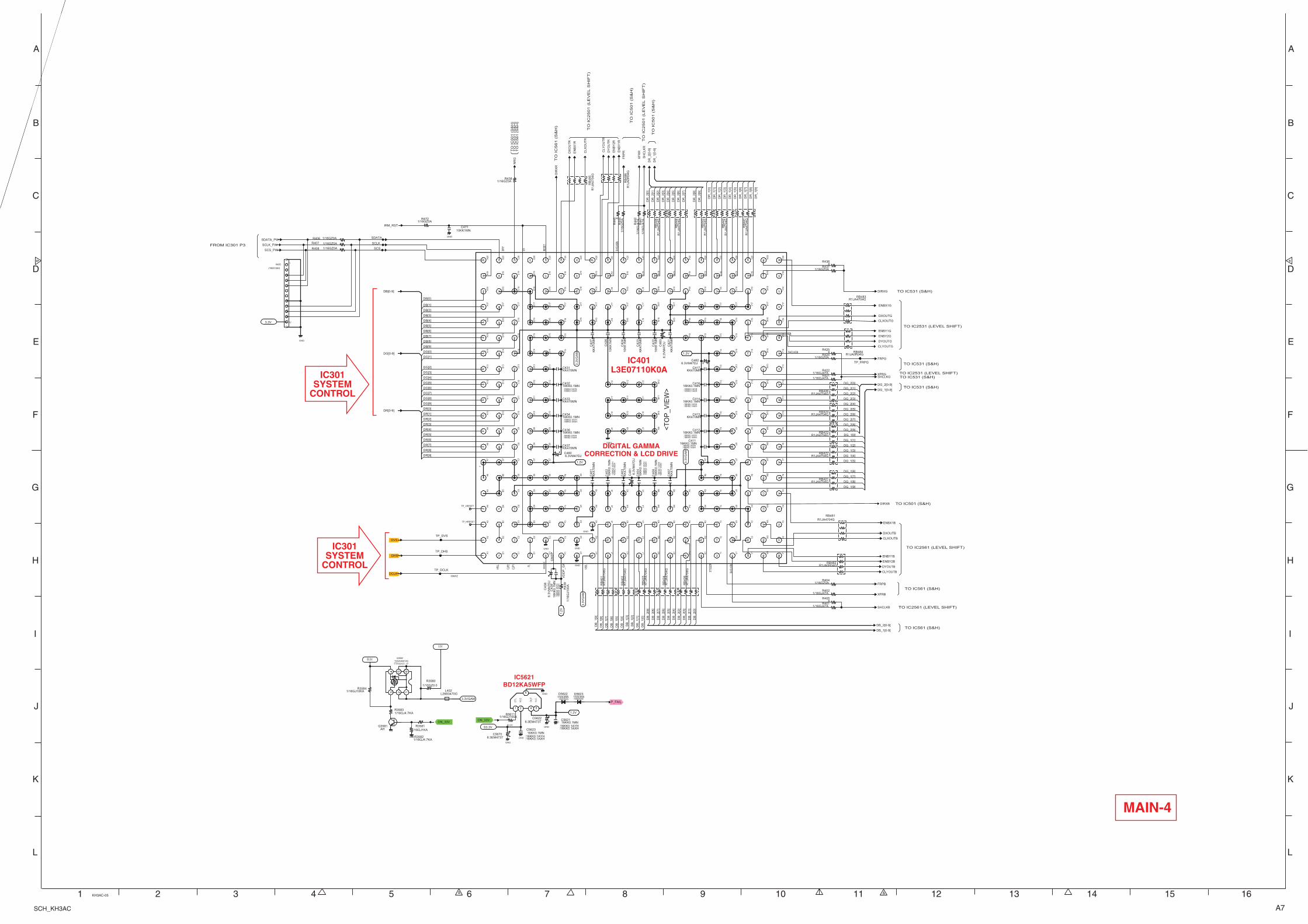
A7SCH_KH3AC
L3E07110K0A
DIGITAL GAMMACORRECTION & LCD DRIVE
IC401
IC5621BD12KA5WFP
IC301SYSTEM
CONTROL
IC301SYSTEM
CONTROL
MAIN-4
SDATA_PW
FRPG
DHS
KK470MNC431
DIRXG
DR[0-9]
DG[0-9]
DG_2[0-9]
NR
G
DG_1[0-9]
SHCLKGXFRG
IRM_RST C47110KK1MN
DCLK
<T
OP
_VIE
W>
1
A1
2
A2
3
A3
4
A4
5
A5
6
A6
7
A7
8
A8
9
A9
10
A10
11
A11
12
A12
13
A13
14
A14
15
A15
16
A16
17
A17
18
A18
19
A19
20
A20
21
B20
22
C20
23
D20
24
E20
25
F20
26
G20
27
H20
28
J20
29
K20
30
L20
31
M20
32
N20
33
P20
34
R20
35
T20
36
U20
37
V20
38
W20
39
Y20
40
Y19
41
Y18
42
Y17
43
Y16
44
Y15
45
Y14
46
Y13
47
Y12
48
Y11
49
Y10
50
Y9
51
Y8
52
Y7
53
Y6
54
Y5
55
Y4
56
Y3
57
Y2
58
Y1
59
W1
60
V1
61
U1
62
T1
63
R1
64
P1
65
N1
66
M1
67
L1
68
K1
69
J1
70
H1
71
G1
72
F1
73
E1
74
D1
75
C1
76
B1
77
B2
78
B3
79
B4
80
B5
81
B6
82
B7
83
B8
84
B9
85
B10
86
B11
87
B12
88
B13
89
B14
90
B15
91
B16
92
B17
93
B18
94
B19
95
C19
96
D19
97
E19
98
F19
99
G19
100 H
19
101 J1
9
102 K
19
103 L1
9
104 M
19
105 N
19
106 P
19
107 R
19
108 T
19
109 U
19
110 V
19
111 W
19
112 W
18
113 W
17
114 W
16
115 W
15
116 W
14
117 W
13
118 W
12
119 W
11
120 W
10
121 W
9
122 W
8
123 W
7
124 W
6
125 W
5
126 W
4
127 W
3
128 W
2
129 V
2
130 U
2
131 T
2
132 R
2
133 P
2
134 N
2
135 M
2
136 L2
137 K
2
138 J2
139 H
2
140 G
2
141 F
2
142 E
2
143 D
2
144 C
2
145 C
3
146 C
4
147 C
5
148 C
6
149 C
7
150 C
8
151 C
9
152 C
10
153 C
11
154 C
12
155 C
13
156 C
14
157 C
15
158 C
16
159 C
17
160 C
18
161 D
18
162 E
18
163 F
18
164 G
18
165 H
18
166 J1
8
167 K
18
168 L1
8
169 M
18
170 N
18
171 P
18
172 R
18
173 T
18
174 U
18
175 V
18
176 V
17
177 V
16
178 V
15
179 V
14
180 V
13
181 V
12
182 V
11
183 V
10
184 V
9
185 V
8
186 V
7
187 V
6
188 V
5
189 V
4
190 V
3
191 U
3
192 T
3
193 R
3
194 P
3
195 N
3
196 M
3
197 L3
198 K
3
199 J3
200 H
3
201 G
3
202 F
3
203 E
3
204 D
3
205 D
4
206 D
5
207 D
6
208 D
7
209
D8
210 D
9
211 D
10
212 D
11
213 D
12
214 D
13
215 D
14
216 D
15
217 D
16
218 D
17
219 E
17
220 F
17
221 G
17
222 H
17
223 J1
7
224 K
17
225 L1
7
226 M
17
227 N
17
228 P
17
229 R
17
230 T
17
231 U
17
232 U
16
233 U
15
234 U
14
235 U
13
236 U
12
237 U
11
238 U
10
239 U
9
240 U
8
241 U
7
242 U
6
243 U
5
244 U
4
245 T
4
246 R
4
247 P
4
248 N
4
249 M
4
250 L4
251 K
4
252 J4
253 H
4
254 G
4
255 F
4
256 E
4
257 E
5
258 E
6
259 E
7
260 E
8
261 E
9
262 E
10
263 E
11
264 E
12
265 E
13
266 E
14
267 E
15
268 E
16
269 F
16
270 G
16
271 H
16
272 J1
6
273 K
16
274 L1
6
275 M
16
276 N
16
277 P
16
278 R
16
279 T
16
280 T
15
281 T
14
282 T
13
283 T
12
284 T
11
285 T
10
286 T
9
287 T
8
288 T
7
289 T
6
290 T
5
291 R
5
292 P
5
293 N
5
294 M
5
295 L5
296 K
5
297 J5
298 H
5
299 G
5
300 F
5
301 F
6
302 F
14
303 F
15
304 P
15
305 R
15
306 R
7
307 R
6
308 G
6
309 J9
310 J1
0
311 J1
1
312 J1
2
313 K
12
314 L1
2
315 M
12
316 M
11
317 M
10
318 M
9
319 L9
320 K
9
321 K
10
322 K
11
323 L1
1
324 L1
0
3.3VGAM
SCLK_PW
SCS_PW
DVS
DB[0-9]
KK
470M
NC
401
KK
470M
NC
403
KK
470M
NC
407
KK470MNC413
KK470MNC417
10K
K1M
NC
422
10K
K1M
NC
424
KK
470M
NC
423
KK
470M
NC
421
10K
K1M
N
C42
6
KK
470M
NC
427
R1
JA4
70
4G
RB
441
R1JA4704GRB426
R1
JA4
70
4G
RB
403
R1
JA4
70
4G
RB
406
R1
JA4
70
4G
RB
402
R1JA4704GRB424
R1
JA4
70
4G
RB
443
R1
JA4
70
4G
RB
446
R1
JA4
70
4G
RB
401
R1JA4704GRB422
R1JA4704GRB423
R1
JA4
70
4G
RB
442
R1
JA4
70
4G
RB
444
R1JA4704GRB421
R1
JA4
70
4G
RB
404
R1JA4704GRB481
R1JA4704GRB483
R1JA0R04GRB484
R1JA0R04GRB482
R1
JA4
70
4G
RB
485
R1
JA0
R0
4G
RB
486
6.3
VM
47
DJ
C48
1
6.3VM47DJC480
6.3
VM
47
DJ
C48
3
6.3VM47DJC482
KK470MNC433
KK470MNC437
ENBX1G
DXOUTG
CLXOUTG
ENBY1G
ENBY2G
DYOUTG
CLYOUTG
6.3
VM
47
DJ
C43
8
TP_VRESET
TP_HRESET
TP_DVS
TP_DHS
TP_DCLK
TP_FRPG
S3.3V
1.2V
P_FAIL
ON_33V
1SS355D5622
:1SS352G1SS355D5623
:1SS352G
1
CT
L
2
VC
C
4
N.C
.
5
OU
T
6
1/1
6G
J47
AR
442
XR436
1/1
6G
Z0
AR
444
1/1
6G
J10
0A
R43
9
1/16GJ47AR421
1/16GJ47AR401
1/16GZ0AR424
1/16GZ0AR438
XR425
XR405
1/16GZ0AR404
1/16GJ47AR422
1/16GZ0AR472
1/1
6G
J47
AR
441
1/16GJ100AR5611
1/16GZ0AR437
1/16GJ47AR402
XR
445
1/16GZ0AR406
1/16GZ0AR407
1/16GZ0AR408
3.3V
SDATA
SCS
SCLK
1.2V
1.2V
1.2V
3.3
VG
AM
3.3
VG
AM
3.3
VG
AM
GND
AHQ3581
1/16GJ4.7KAR3582
TXXAVB012GQ3582
:TTPC6107---P
1234 5 6
3.3V
S3.3V
1/16GJ10KAR3584
ON_33V
1/16GJ4.7KAR3583
1/16GJ1KAR3581
L26B3470GL402
6.3EM473TC5622
6.3EM473TC5670
SH
CL
KR
DR
_2
[0-9
]
XF
RRC
LY
OU
TR
DY
OU
TR
DIR
XR
FR
PRE
NB
Y2R
EN
BY
1R
DR
_1
[0-9
]
CLX
OU
TR
DX
OU
TR
EN
BX
1R
ENBY1B
ENBY2B
DB_1[0-9]
DYOUTB
FRPB
CLYOUTB
CLXOUTB
ENBX1B
DXOUTB
DB_2[0-9]
SHCLKB
XFRB
DIRXB
1/10GZ0.0
R3580
16KK0.1MNC412
:16KK0.1AYH:16KK0.1AXH
16KK0.1MNC5621
:16KK0.1AYH:16KK0.1AXH
16
KK
0.1
MN
C40
2
:16K
K0.
1AY
H:
16K
K0.
1AX
H
16KK0.1MNC411
:16KK0.1AYH:16KK0.1AXH
16KK0.1MNC434
:16KK0.1AYH:16KK0.1AXH
16
KK
0.1
MN
C40
6
:16K
K0.
1AY
H:
16K
K0.
1AX
H
16
KK
0.1
MN
C43
9
:16K
K0.
1AY
H:1
6KK
0.1A
XH
16KK0.1MNC416
:16KK0.1AYH:16KK0.1AXH
16KK0.1MNC436
:16KK0.1AYH:16KK0.1AXH
16KK0.1MNC414
:16KK0.1AYH:16KK0.1AXH
16KK0.1MNC5623
:16KK0.1AYH:16KK0.1AXH
16KK0.1MNC432
:16KK0.1AYH:16KK0.1AXH
16
KK
0.1
MN
C40
4
:16K
K0.
1AY
H:1
6KK
0.1A
XH
J10ES126G
K406 11
2
3
4
10
5
11
6
1212
7
8
9
GND
GND
GND
GND
GND
GND
GND
GND
GND
GND
GND
GND
DG[6]
DG_2[8]
DG_2[9]
DG_1[2]
DB[9]
DG_2[5]
DG_2[7]
DR[5]
DR[9]
DG_1[1]
DR[4]
VD
DP
_G
A
DB[7]
DG[5]
DG_1[8]
DG[7]
DR[3]
DR[6]
DG_2[1]
DB[5]
DR[2]
DG[4]
DG[1]
DR[7]
DG_1[5]
DG[8]
DG_1[0]
DG[0]
DG_1[4]
DG_1[3]
DG[3]
DR[1]
DG[9]
DR[8]
DB[2]
DG_1[7]
DG[2]
DB[8]
DG_2[2]
DG_2[0]
DR[0]
DG_1[9]
DG_1[6]
DG_2[4]
DG_2[3]
GN
DP
DB[3]
DB[4]
DB[1]
DG_2[6]
DB[6]
68MHZ
68M
HZ
DB[0]
S3.3V
DR
_1[8
]
DR
_2[1
]
DR
_1[7
]
DR
_2[5
]
DR
_2[8
]
DR
_1[9
]
DR
_1[6
]
DR
_2[4
]
DR
_1[1
]
DR
_2[9
]
DR
_1[3
]
DR
_1[2
]
DR
_2[7
]
DR
_1[4
]
DR
_2[0
]
DR
_1[5
]
DR
_1[0
]
DR
_2[6
]
DB
_1[7
]
DB
_2[7
]
DB
_2[2
]
DB
_2[9
]
DB
_2[1
]
DB
_2[3
]
DB
_2[0
]
DB
_1[8
]
DB
_1[0
]
DB
_2[6
]
DB
_1[1
]
DB
_1[9
]
DB
_1[4
]
DB
_1[6
]
DB
_1[2
]
DB
_1[3
]
DB
_2[5
]
DB
_2[4
]
DB
_2[8
]
DB
_1[5
]
DR
_2[2
]
DR
_2[3
]
TO IC2531 (LEVEL SHIFT)
PL
EN SHCL
KBN
HPLL
CLP1
CLP2
TO IC531 (S&H)
DIRY
TO
IC
501 (
S&
H)
FROM IC301 P3
TO IC2531 (LEVEL SHIFT)
STSQ
ER
VSEL
SHCL
KRN
SHCLKGN
TO IC531 (S&H)
RESE
T
TO IC531 (S&H)
TO
IC
561 (
S&
H)
TO IC531 (S&H)
TO
IC
531 (
S&
H)
TO
IC
561 (
S&
H)
TO IC501 (S&H)
TO IC2561 (LEVEL SHIFT)
TO IC561 (S&H)
TO IC2561 (LEVEL SHIFT)
TO IC561 (S&H)
TO
IC
501 (
S&
H)
TO
IC
2501 (
LE
VE
L S
HIF
T)
TO
IC
2501 (
LE
VE
L S
HIF
T)
TO
IC
501 (
S&
H)
1 2 3 4 5 6 7 8 9 10 11 12 13 14 15 16
A
B
C
D
E
F
G
H
I
J
K
L
A
B
C
D
E
F
G
H
I
J
K
L
KH3AC-05
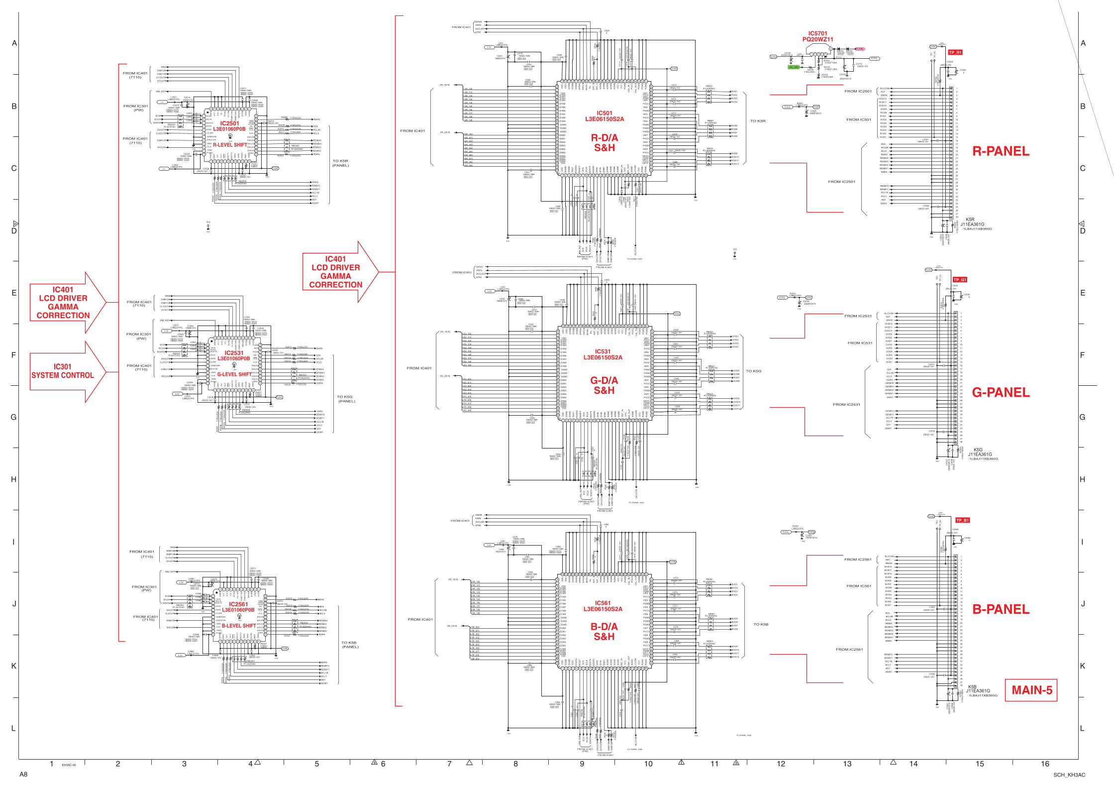
A8 SCH_KH3AC
IC401LCD DRIVER
GAMMACORRECTION
IC301SYSTEM CONTROL
R-D/AS&H
G-D/AS&H
B-D/AS&H
TP_R1
TP_G1
TP_B1
R-PANEL
G-PANEL
B-PANEL
IC501L3E06150S2A
IC531L3E06150S2A
IC561L3E06150S2AL3E01060P0B
B-LEVEL SHIFT
IC2561
L3E01060P0B
G-LEVEL SHIFT
IC2531
L3E01060P0B
R-LEVEL SHIFT
IC2501
IC401LCD DRIVER
GAMMACORRECTION
IC5701PQ20WZ11
MAIN-5
SCS
C2503X
1 SCS
2 SCLK
3 SDATA
4 DIVS
5 DXIN
6 CLXIN
7 ENBX5IN
8 ENVX1IN
9 GND
10 CLK
11 GND
12PVDD
13
HV
DD
14
DIR
Y
15
DY
16
CLY
17 18
EN
VY
1
19
EN
VY
2
20
NR
G
21
GN
D
22
HV
DD
23
IRE
F
24
GN
D 25DIRX
26ENVX1
27ENVX2
28ENVX3
29ENVX4
30ENVX5
31CLX
32
33DX
34HVDD
35
MON
36
GND
37
AV
DD
38
GN
D
39
DV
DD
40
NR
GIN
41
EN
BY
2IN
42
EN
BY
1IN
43
CLY
IN
44
DY
IN
45
TS
46
A10
47
A11
48
XR
ES
49
SDATA
C2502X
C2501X
IRM_RST
SCLK
GDIRX
1
SCS2SCLK
3 SDATA
4 DIVS
5 DXIN
6 CLXIN
7 ENBX5IN
8ENVX1IN
9 GND
10 CLK
11 GND
12PVDD
13
HV
DD
14
DIR
Y
15
DY
16
CLY
17 18
EN
VY
1
19
EN
VY
2
20
NR
G
21
GN
D
22
HV
DD
23
IRE
F
24
GN
D 25DIRX
26ENVX1
27ENVX2
28ENVX3
29ENVX4
30ENVX5
31CLX
32
33DX
34HVDD
35MON
36GND
37
AV
DD
38
GN
D
39
DV
DD
40
NR
GIN
41
EN
BY
2IN
42
EN
BY
1IN
43
CLY
IN
44
DY
IN
45
TS
46
A10
47
A11
48
XR
ES
49
GMON
GCLX
GDY
DXOUTG
DYOUTG
GDIRY
NRG
GNRG
GCLY
15.5VG
CLYOUTG
GCLXB
ENBY1G
IRM_RST
ENBY2G
GDX
GCLYB
ENBX1G
SHCLKG
CLXOUTG
1
SCS2SCLK
3 SDATA
4 DIVS
5 DXIN
6 CLXIN
7 ENBX5IN
8 ENVX1IN
9 GND
10 CLK
11 GND
12PVDD
13
HV
DD
14
DIR
Y
15
DY
16
CLY
17 18
EN
VY
1
19
EN
VY
2
20
NR
G
21
GN
D
22
HV
DD
23
IRE
F
24
GN
D 25DIRX
26ENVX1
27ENVX2
28ENVX3
29ENVX4
30ENVX5
31CLX
32
33DX
34HVDD
35
MON
36
GND
37
AV
DD
38
GN
D
39
DV
DD
40
NR
GIN
41
EN
BY
2IN
42
EN
BY
1IN
43
CL
YIN
44
DY
IN
45
TS
46
A10
47
A11
48
XR
ES
49
NRG
IRM_RST
IRM
_R
ST
SC
S
SC
LK
SD
AT
A
GVID9
GVID1
SC
LK
GVID6
EN
BY
1G
GVID11
GVID3
DX
OU
TG
GVID8
KK
10
00
AY
HC
546
SC
S
GVID5
GVID10
GVID2
GLC
CO
M
SD
AT
A
EN
BY
2G
GVID7
IRM
_R
ST
GVID12
GVID4
DY
OU
TG
GDIRY
GVID10
GVID1
GVID9
GCLY
GENBY1
GVID8
GDIRX
GLCCOM
GVID7
GDY
GDY
GCLX
GVID6
GENBX4
GCLXB
GVID5
GCLYB
GMON
GNRG
GENBX1
GVID4
GVID12
GDX
GVID3
GENBY2
GVID11
GENBX3
GVID2
GENBX2
SC
LK
SD
AT
A
IRM
_R
ST
SC
S
SHCLKG
FRPG
DIRXG
XFRG
J11EA361GK5B
:1LB4J11XB360G
30
31
32
33
34
35
10
36
11
12
13
14
15
16
17
18
19
1
2
3
20
21
4
22
5
23
6
24
7
25
8
26
9
27
28
29
37
38
J11EA361GK5R
:1LB4J11XB360G
30
31
32
33
34
35
10
36
11
12
13
14
15
16
17
18
19
1
2
3
20
21
4
22
5
23
6
24
7
25
8
26
9
27
28
29
37
38
XC585
25K
K11D
C56
5
16EM101VC584
XC3565
16EM101VC554
XC555
25K
K11D
C53
5
XC3535
16EM101VC2514
16EM101VC524
XC525
25K
K11D
C50
5
XC3505
R1JA1014GRB2501
SCLK
SCS
R1JA1014GRB2531
SDATA
SCLK
SCS
R1JA1014GRB2561
SDATA
1
VD
D
51
PG
ND
2
DG
ND
52
PG
ND
3
DG
ND
53
PG
ND
4
TE
ST
54
CA
L_O
UT
5
PO
WS
V
55
PV
CC
6
RE
SE
T
56
CA
L_IN
7
SC
S
57
PG
ND
8
SC
LK
58
VC
C
9
SD
AT
A
59
VC
C
60
AG
ND
61
AG
ND
62
AG
ND
63
AG
ND
64
AG
ND
65
SH
T_I
66
SH
T_O
67
R/L
68
INV
IN
69
SH
CLK
100
VDD
70
XF
RIN
71
DG
ND
72
DG
ND
73
DG
ND
74
VD
D
75
VD
D
76
VDD
77
D1IN078
D1IN179D1IN2
80 D1IN3
81 D1IN4
10
AD
DR
0
82 D1IN5
11
DX
IN
83 D1IN6
12
DY
IN
84 D1IN7
13
EN
BY
85 D1IN8
14
AG
ND
86 D1IN9
15
AG
ND
87 DGND
16
AG
ND
88 DGND
17
AG
ND
89 DGND
18
RE
F_IN
19
VC
C
90 D2IN0
91 D2IN1
20
RE
F_O
UT
92 D2IN2
21
AG
ND
93 D2IN3
22
LCC
OM
94 D2IN4
23
VC
C
95 D2IN5
24
PG
ND
96 D2IN6
25
PG
ND
97D2IN7
26
VID1298
D2IN8
27
PVCC
99
D2IN928
VID11 29PGND
30VID10
31PVCC
32VID9
33PGND
34VID8
35PVCC
36VID7
37PGND
38PGND
39PGND
40VID6
41PVCC
42VID5
43PGND
44VID4
45PVCC
46VID3
47PGND
48
VID2
49
PVCC
50
VID1
1
VD
D
51
PG
ND
2
DG
ND
52
PG
ND
3
DG
ND
53
PG
ND
4
TE
ST
54
CA
L_O
UT
5
PO
WS
V55
PV
CC
6
RE
SE
T
56
CA
L_IN
7
SC
S
57
PG
ND
8
SC
LK
58
VC
C
9
SD
AT
A
59
VC
C
60
AG
ND
61
AG
ND
62
AG
ND
63
AG
ND
64
AG
ND
65
SH
T_I
66
SH
T_O
67
R/L
68
INV
IN
69
SH
CLK
100
VDD
70
XF
RIN
71D
GN
D72
DG
ND
73
DG
ND
74
VD
D
75
VD
D
76
VDD
77
D1IN078
D1IN179D1IN2
80 D1IN3
81 D1IN4
10
AD
DR
0
82 D1IN5
11
DX
IN
83 D1IN6
12
DY
IN
84 D1IN7
13
EN
BY
85 D1IN8
14
AG
ND
86 D1IN9
15
AG
ND
87 DGND
16
AG
ND
88 DGND
17
AG
ND
89 DGND
18
RE
F_IN
19
VC
C
90 D2IN0
91 D2IN1
20
RE
F_O
UT
92 D2IN2
21
AG
ND
93 D2IN3
22
LCC
OM
94 D2IN4
23
VC
C
95 D2IN5
24
PG
ND
96 D2IN6
25
PG
ND
97D2IN7
26
VID1298
D2IN8
27
PVCC
99
D2IN928
VID11 29PGND
30VID10
31PVCC
32VID9
33PGND
34VID8
35PVCC
36VID7
37PGND
38PGND
39PGND
40VID6
41PVCC
42VID5
43PGND
44VID4
45PVCC
46VID3
47PGND
48
VID2
49
PVCC
50
VID1
DG_2[0-9]
DG_1[0-9]
XC2531
XC2532
XC2533
XC2561
XC2562
XC2563
KK
10
00
AY
HC
516
R1
JA1
01
4G
RB
825
8
X
C58
1
X
C58
2
X
C58
3
R1
JA1
01
4G
RB
8259
X
C52
1
X
C52
2
X
C52
3
R1
JA1
01
4G
RB
8260
X
C55
1
X
C55
2
XC55
3
KK
10
00
AY
HC
576
GENBX4
GENBX3
GENBX2
GENBX1
GENBY2
GENBY1
16EM101VC2544
3.3V
3.3V
3.3V
3.3V
3.3V16EM101V
C2574
3.3V
3.3V
3.3V
3.3V
R1JA0R04GRB501
R1JA0R04GRB502
R1JA0R04GRB503
R1JA0R04GRB532
R1JA0R04GRB531
R1JA0R04GRB533
R1JA0R04GRB562
R1JA0R04GRB561
R1JA0R04GRB563
TP
_G1
TP
_B1
TP
_R1
TE
2
TE
1
TE
3
TE4
TE5
1/1
6G
J47K
AR
3502
1/1
6G
Z0
A
R59
0X
R58
0
1/1
6G
J10
0K
AR
3503
1/1
6G
Z0
AR
506
1/1
6G
Z0
A
R59
1
1/1
6G
J10
0K
AR
35
33
XR
518
1/1
6G
F1
KA
R57
0
1/16GJ100KA
R2551
1/1
6G
Z0A
R53
7
XR
581
XR
548
1/1
6G
J47K
AR
35
62
1/16GJ100KA
R2581
1/1
6G
Z0
AR
507
1/1
6G
J10
AR
571
1/1
6G
Z0
A
R59
2
1/1
6G
Z0
AR
519
XR
582
1/16GJ100KA
R2521
1/1
6G
F1
KA
R51
0
1/1
6G
J10
AR
541
XR
578
1/1
6G
J47K
AR
3532
1/1
6G
Z0
AR
579
1/1
6G
J10
0K
AR
35
63
1/1
6G
J10
AR
511
1/1
6G
Z0A
R56
6
1/1
6G
Z0
AR
567
1/1
6G
Z0A
R54
9
1/1
6G
Z0A
R53
6
1/1
6G
F1
KA
R54
0
ON_150V
S16V
1 2 3 4 5
6 P_FAIL
NT15.5V
1SS355D5704
:1SS352G
1/16GJ1KAR5705
15.5VL
J11EA361GK5G
:1LB4J11XB360G
30
31
32
33
34
35
10
36
11
12
13
14
15
16
17
18
19
1
2
3
20
21
4
22
5
23
6
24
7
25
8
26
9
27
28
29
37
38
1/16GJ22AR2508
1/16GJ22AR2509
1/16GJ22AR2510
1/16GJ22AR2511
1/16GJ22AR2515
1/16GJ22AR2513
1/16GJ22AR2512
1/16GJ22AR2514
1/16GJ22AR2518
1/16GJ22AR2516
1/16GJ22AR2517
1/16GJ22AR2519
1/16GJ22AR2523
1/16GJ22AR2525
1/16GJ22AR2527
L3BE221PGL2531
L3BE221PGR2501
1
2
L3BE221PGL2502
L3BE221PGR2531
1
2
L3BE221PGL2501
L3BE221PGL2532
L3BE221PGL2561
L3BE221PGL2562
1/16GF240AR5703
1/16GF1.8KAR5702
1/16GF10KAR5701
L3BE221PGL561
L3BE221PGL3530
L3BE221PGL3532
L3BE221PGL501
L3BE221PGL3533
L3BE221PGL531
1/1
6G
J22
AR
25
32
1/1
6G
J22
AR
253
3
1/1
6G
J22
AR
25
341
/16
GJ2
2A
R2
535
1/1
6G
J22
AR
25
37
1/1
6G
J22
AR
25
36
1/1
6G
J22
AR
2539
1/1
6G
J22
AR
2540
1/1
6G
J22
AR
2538
R1JA2204GRB2507
R1JA2204GRB2506
R1JA2204GRB2505
25KZ0.1AY
C3564
25
KZ
0.1
AY
C35
66
25KZ0.1AY
C538
25
KZ
0.1
AY
C3
536
25KZ0.1AYC570
25KZ0.1AYC2507
25KZ0.1AYC512
25KZ0.1AYC539
25KZ0.1AYC2513
25
KZ
0.1
AY
C35
06
25KZ0.1AYC509
25
KZ
0.1
AY
C57
7
25KZ0.1AYC3561
25KZ0.1AYC541
25KZ0.1AYC572
25KZ0.1AYC2506
25KZ0.1AYC510
25KZ0.1AY
C3504
25KZ0.1AYC511
25KZ0.1AY
C3562
25
KZ
0.1
AY
C54
7
25
KZ
0.1
AY
C57
5
25KZ0.1AYC2537
25KZ0.1AYC508
25
KZ
0.1
AY
C53
7
25KZ0.1AYC3501
25
KZ
0.1
AY
C50
6
25KZ0.1AYC571
25KZ0.1AY
C3532
25
KZ
0.1
AY
C54
5
25
KZ
0.1
AY
C56
6
25KZ0.1AY
C2536
25
KZ
0.1
AY
C50
7
25KZ0.1AYC540
25KZ0.1AY
C3534
25KZ0.1AYC573
25
KZ
0.1
AY
C53
6
25KZ0.1AY
C2573
25KZ0.1AYC2567
25KZ0.1AYC513
25
KZ
0.1
AY
C56
7
25KZ0.1AYC3531
25KZ0.1AYC542
25KZ0.1AY
C568
25KZ0.1AY
C3502
25
KZ
0.1
AY
C51
7
25KZ0.1AYC543
25KZ0.1AYC2543
25KZ0.1AYC2566
25
KZ
0.1
AY
C51
5
25KZ0.1AYC569
25KZ0.1AYC5710
25KZ0.1AYC5704
L3BE221PGR2561
1
2
15.5VG15.5VL
15.5VG
15.5VG
CLYOUTB
ENBY2B
ENBY1B
DYOUTB
CLXOUTB
ENBX1B
DXOUTB
SHCLKB
CLXOUTR
ENBX1R
DXOUTR
SHCLKR
ENBY1R
DYOUTR
NRG
ENBY2R
CLYOUTR
FRPB
DIRXB
XFRB
SHCLKB
DB_1[0-9]
DB_2[0-9]
SHCLKR
FRPR
DIRXR
XFRR
DR_2[0-9]
DR_1[0-9]
RVID5
RDY
RDX
RMON
RENBX2
RENBX1
RCLXB
RNRG
RVID11
RENBX3
RVID12
RVID10
RVID8
RDIRY
RENBY2
RVID9
RVID1
RLCCOM
RCLY
RENBX4
RVID7
RDY
RVID3
RDIRX
RCLX
RVID2
RVID6
RVID4
RENBY1
BCLX
BLCCOM
BDIRX
BDY
BENBX4
BMON
BENBX3
BVID12
BENBX2
BVID11
BENBX1
BVID10
BNRG
BVID9
BENBY2
BVID8
BENBY1
BVID7
BCLYB
BVID6
BCLY
BVID5
BDY
BVID4
BDIRY
BVID3
BVID2
BVID1
BDX
BCLXB
RCLYB
RVID9
RVID3
RVID7
RVID12
RVID2
RVID1
RVID11
RVID8
RVID10
RVID5
RVID4
RVID6
BVID6
BVID7
BVID1
BVID8
BVID2
BVID9
BVID3
BVID10
BVID4
BVID11
BVID5
BVID12
BENBX3
BCLY
BDIRY
BENBX2
BCLYB
BNRG
BDX
BENBX1
BENBY2
BENBY1
BDIRX
BCLX
BMON
BDY
BENBX4
BCLXB
RNRG
RENBY2
RDIRX
RENBY1
RCLX
RCLY
RCLXB
RCLYB
RDY
RENBX4
RDIRY
RENBX3
RMON
RENBX2
RDX
RENBX1
DY
OU
TR
DX
OU
TR
EN
BY
2R
EN
BY
1R
EN
BY
2B
DX
OU
TB
DY
OU
TB
EN
BY
1B
BLC
CO
MR
LC
CO
M
1SS355D5703
:1SS352G
R1JA2204G
RB2504
R1JA2204G
RB2502
R1JA2204G
RB2503
15.5VR
15.5VR
15.5VL
15.5VR
15.5VR
15.5VB
15.5VB
15.5VL 15.5VB
15.5VB
16KK0.1MNC2504
:16KK0.1AYH:16KK0.1AXH
16KK0.1MNC559
:16KK0.1AYH:16KK0.1AXH
16KK0.1MNC534
:16KK0.1AYH:16KK0.1AXH
16KK0.1MNC579
:16KK0.1AYH:16KK0.1AXH
16KK0.1MNC501
:16KK0.1AYH:16KK0.1AXH
16KK0.1MNC531
:16KK0.1AYH:16KK0.1AXH
16KK0.1MNC564
:16KK0.1AYH:16KK0.1AXH
16KK0.1MNC532
:16KK0.1AYH:16KK0.1AXH
16KK0.1MNC2569
:16KK0.1AYH:16KK0.1AXH
16KK0.1MNC2571
:16KK0.1AYH:16KK0.1AXH
16KK0.1MNC533
:16KK0.1AYH:16KK0.1AXH
16KK0.1MNC2564
:16KK0.1AYH:16KK0.1AXH
16KK0.1MNC589
:16KK0.1AYH:16KK0.1AXH
16KK0.1MNC2541
:16KK0.1AYH:16KK0.1AXH
16KK0.1MNC2534
:16KK0.1AYH:16KK0.1AXH
16KK0.1MNC2539
:16KK0.1AYH:16KK0.1AXH
16KK0.1MNC563
:16KK0.1AYH:16KK0.1AXH
16KK0.1MNC502
:16KK0.1AYH:16KK0.1AXH
16KK0.1MNC529
:16KK0.1AYH:16KK0.1AXH
16KK0.1MNC2511
:16KK0.1AYH:16KK0.1AXH
16KK0.1MNC561
:16KK0.1AYH:16KK0.1AXH
16KK0.1MNC562
:16KK0.1AYH:16KK0.1AXH
16KK0.1MNC2542
:16KK0.1AYH:16KK0.1AXH
16KK0.1MNC2512
:16KK0.1AYH:16KK0.1AXH
16KK0.1MNC549
:16KK0.1AYH:16KK0.1AXH
16KK0.1MNC2509
:16KK0.1AYH:16KK0.1AXH
16KK0.1MNC2572
:16KK0.1AYH:16KK0.1AXH
16KK0.1MNC519
:16KK0.1AYH:16KK0.1AXH
16KK0.1MNC503
:16KK0.1AYH:16KK0.1AXH
16KK0.1MNC504
:16KK0.1AYH:16KK0.1AXH
25EM1001XC5705
25
EM
10
01
XC
35
63
25
EM
10
01
XC
3503
25EM1001XC2565
25
EM
10
01
XC
35
33
25EM1001XC2535
25EM1001X
C5709
25EM1001XC2505
GND
GND
GND
GND
GND
GND
GND
GND
GND
GND
GND
GND
GND
GND
GND
GND
GND
GND
GND
GND
GND
GND
GND
GND
GND
DG_1[0]
DG_1[1]
DG_1[2]
DG_1[3]
DG_1[4]
DG_1[5]
DG_1[6]
DG_1[7]
DG_1[8]
DG_1[9]
DG_2[0]
DG_2[1]
DG_2[2]
DG_2[3]
DG_2[4]
DG_2[5]
DG_2[6]
DG_2[7]
DG_2[8]
DG_2[9]
DB_1[0]
DB_2[6]
DB_2[2]
DB_2[0]
DB_2[9]
DB_2[8]
DB_2[7]
DB_2[5]
DB_1[9]
DB_2[4]
DB_1[8]
DB_2[3]
DB_1[7]
DB_2[1]
DB_1[6]
DB_1[5]
DB_1[4]
DB_1[3]
DB_1[2]
DB_1[1]
DR_1[6]
DR_1[5]
DR_1[4]
DR_1[3]
DR_1[2]
DR_1[1]
DR_1[0]
DR_2[9]
DR_2[8]
DR_2[7]
DR_2[6]
DR_2[5]
DR_2[4]
DR_2[3]
DR_2[2]
DR_2[1]
DR_2[0]
DR_1[9]
DR_1[8]
DR_1[7]
FROM IC401(7110)
FROM IC401
(PANEL)
(7110)
(7110)
FROM IC401
TO K5G
(PANEL)
(7110)
FROM IC401
FROM IC401
(PANEL)
(7110)
(7110)
FROM IC401
FROM IC401
FROM IC401
TO K5G
TO K5R
FROM IC401
FROM IC401
FROM IC501
FROM IC2501
FROM IC531
FROM IC561FROM IC301(PW)
FROM IC301(PW)
FROM IC301(PW)
FROM IC301(PW)
FROM IC301(PW)
FROM IC301(PW)
TO PANEL K5B
TO PANEL K5G
TO PANEL K5R
FROM IC2531
FROM IC2561
FROM IC2501
FROM IC2531
FROM IC2561
FROM IC401
FROM IC401
FROM IC401
TO K5B
FROM IC401
FROM IC401
TO PANEL K5B
1 2 3 4 5 6 7 8 9 10 11 12 13 14 15 16
A
B
C
D
E
F
G
H
I
J
K
L
A
B
C
D
E
F
G
H
I
J
K
L
KH3AC-06
CLX
CLY
CLX
CLY
CLY
CLX
TO K5B
TO K5R
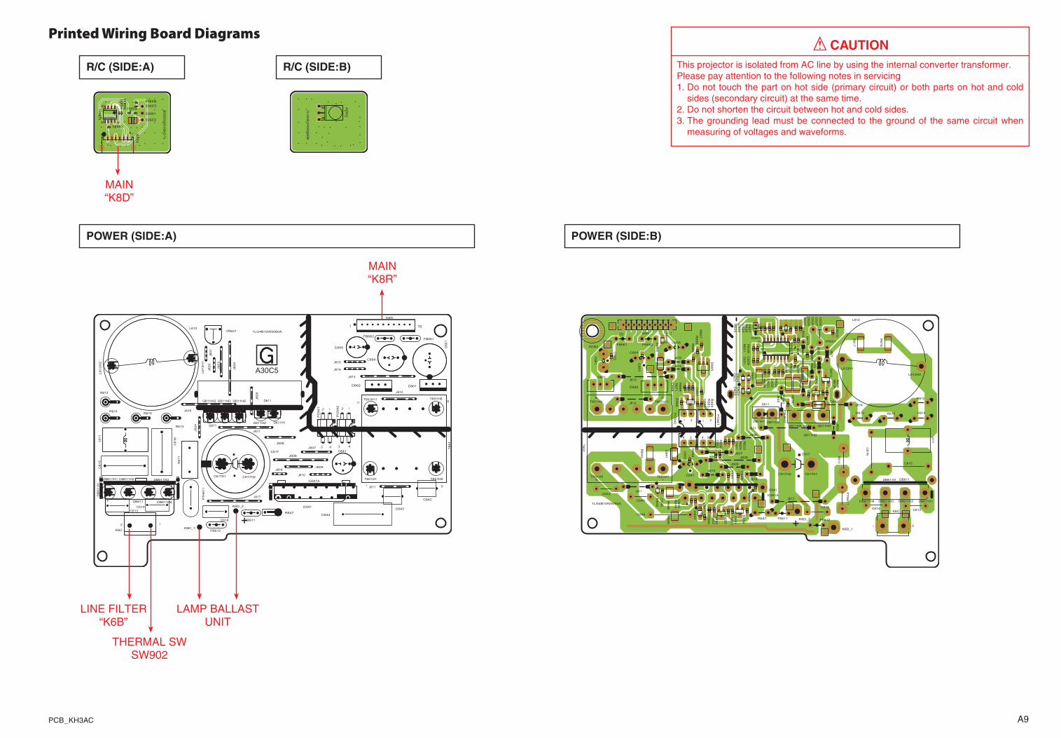
A9PCB_KH3AC
Printed Wiring Board Diagrams! cAutIoN
This projector is isolated from AC line by using the internal converter transformer.Please pay attention to the following notes in servicing1. Do not touch the part on hot side (primary circuit) or both parts on hot and cold
sides (secondary circuit) at the same time.�. Do not shorten the circuit between hot and cold sides.3. The grounding lead must be connected to the ground of the same circuit when
measuring of voltages and waveforms.
H
H
H
H
HH
H
H
H
HH
H
H
HH
HH
H
H1LG4B10W0060A
K6D_1
K6D_2
+FB611
FB612
12
43
PC
64
1 12
43
PC
642
R612
R613
R614
IC641A
R615
R647C613
C614
C618
C642
C643
VR621
C641
2 1
K6C
C644
FB662FB661
1 10
K6R
C664
C665
D661
IC641
D662
11 6
51
T6
51
L6
11
J613
J617
J607
J608
J615
J603
J60
1
J612
J609J618
J610
J614
R6
11
C66
1J606
J611
J620
+
DB611
C617
Q611
D611
L612
J621J624
J616
DB
61
1H
J604
C615
C616
J605
PT
H6
11
A30C5
Q611HD
DB611H1
Q611HG
DB611H2C617H1
T651H11
T651H1
Q611HS
D611H2 D611H1
L6
12
H1
T651H5
DB611H4
DB611H3C617H2
L6
12
H2
T651H6
PoWer (SIde:A)
1LG
4B
10W
0050B
C2903
145 8
IC8831
1 6
K2
9D
R883
1R
883
2
R2901
R2903
C2901
C2902
C8833
r/c (SIde:A) r/c (SIde:B)
1LG
4B
10W
0050B
A2901
MAIN “K8D”
PoWer (SIde:B)
1LG4B10W0060A
K6D_1
K6D_2
+FB611 FB612
34
21
PC
64
1
34
21
PC
642
R612
R613 R614
IC641A
R615
R647
C613C614C618
C642
C643
VR621
C641
1 2
K6CC644
FB662FB661
110 K6R
C664
C665
D661
IC641
D662
1
5
6 11
T6
51
L6
11
J613
J617
J607J608
J615 J603
J60
1
SCB4
J612
J609
J618
J610
J614
R6
11
C66
1
J606
J611
J620
DB611
C617
Q611
D611
L612
J621
J624
J616
DB611H
J604
C615
C616
J605
PT
H6
11
R6
52
R6
54
R6
53
R6
51
R6
16
R6
17
R6
37
R6
38
R6
41
R6
42
R6
24
R6
32R
63
1
R6
43
R6
33
R6
46
R6
34
R6
44
R6
35
R6
45
R6
39
R6
56
R6
36
R6
19
R6
55
R6
18
R6
22
R6
23
R6
28
R6
26
R6
25
C654
R6
29
R6
27
R6
65
R6
66
R6
67
R6
63
R6
64
R6
68
R6
69
R6
71
C648
C629
C631
C645
C632
C633
C628
C646
C627
C649
C651
C621
C623
C622
C624
C652
C653
C626
C625
FB
663
C662
C663
C667
C668
D612
D6
23
D6
24
D6
21
D6
22
D6
41
D6
42
1 8
916IC621
D6
25
D6
63
D6
65
Q6
52
Q6
51
Q6
12
Q6
13
Q6
62
PT
H6
12
D6
43
C647
Q611HD
DB611H1
Q611HG
DB611H2
C617H1
T651H11
T651H1
Q611HSD611H2D611H1
L612H1
T651H5
DB611H4 DB611H3
C617H2
L612H2
T651H6
LINE FILTER“K6B”
THERMAL SWSW90�
LAMP BALLASTUNIT
MAIN“K8R”
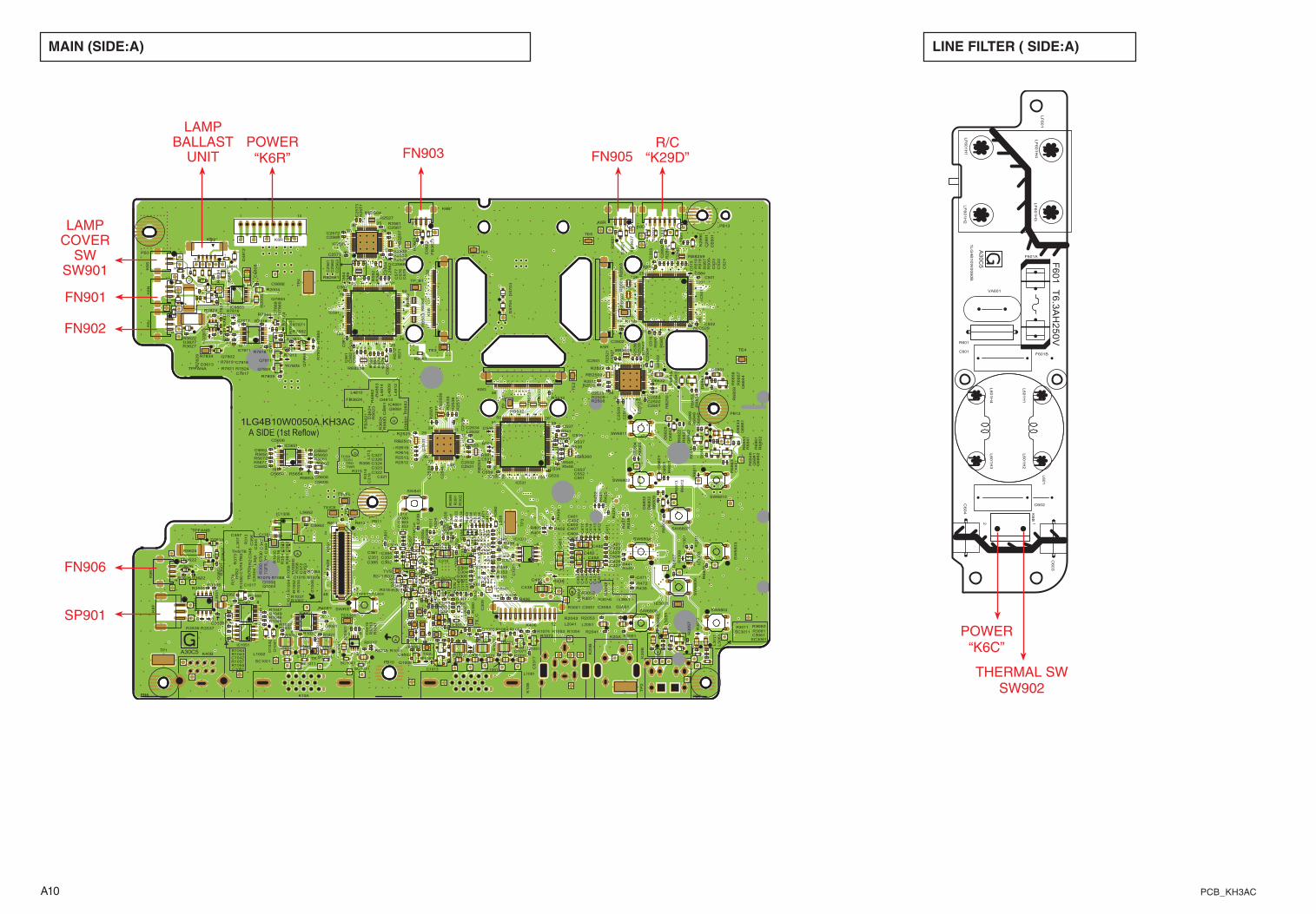
A10 PCB_KH3AC
MAIN (SIde:A)
1LG4B10W0050A.KH3ACA SIDE (1st Reflow)
A
A
B
B
H
H
D
D
K10A
K1
0B
PB3
PB6
K30
B
PB7
1 10
K8R
K20A
K20B
K40B
12
4748
K8
01
PB10
PB11
PB12
PB13
R7
87
4
R401R402
D3613
R40
4
D3614
R7878
R405
R7
87
9
R406R407
D3
61
7
R408
C3061
C4001
C2
89
1
C4002
C2
89
2
R7881
R7882R7
88
3
R7
88
4
D3
62
1
L2
56
2
D3
62
3
D3
62
4
R3
62
1
D3626
D3627
R3
62
3
R3
62
4R
80
1
R3626
R3627
SC1001
D3051
R4
21
R3051
R80
9
R42
2R3052
R42
4
R42
5
R1
30
9
R3056
8 5
1 4 IC1
30
3
R3
05
7
1 25
5175
50
26
76
100
IC561
IC1306
R812R813
R1
311
SC1011
D2
89
1
L1002
D2
89
2
R2
89
0
R3061
R4001
R3062
R2
89
2
R43
6R
43
7
R438
R439
SW841
1
8 9
16IC4001
TE5001
SC1021
C401C402
L1012
L5662
C403
C4
80
8
C404
R441
L3
53
1
C406
C407
R445
C1351
C411
SC1031
C4
12
L1022
C4
13
TV
IDE
O
C4
14
C4
16
C4
17
Y
TCS0
C421
TCS1
L1031SC1041
C422C423C424
C2501
C426
C2502
C427
C2503
C2
50
4
C1371
C2
50
7
C2
50
9
L1041
C4
31
TB
2D
48
12
C4
32
D4813
C4
33
C4
34
C2511
R472C4
36
136
K5B
C2
51
2
C4
37
C2513
C438
C439
136K5G
L1051
TP_B1
36
1
K5R
3 1
K6B
T3VFL
TAFETST3
31
K6J
31
K6K
L1061
3
1
K6N
R2508
C5605
1
1225
36
24 13
4837
IC2501
C2531
R2509
C5606
C2532
3 1
K6R
TS
OG
C2533
C5608
R4
83
4
C2534
1
45
8
IC1371
C2
53
6C2
53
7
R2510
C2
53
9
R2511
R2512R2513R2514
L1071
R2515
TE1
TE
2
TE3
R2
51
7
TE4
TE5
C2
54
1
16K8D
C9882
13
K8F
15
K8H
Q9881
L301
R2
52
1
L302
L303
R2523
L304
C471
L1081
RB
50
1
R2525
L306
RB
50
2
R5
21
3
L307
R2527
RB
50
3
R898
L308
R5215
L309
1
2K8S
L311
L312
R2532
L3
13
R2533
C480
L3
14
RB8258
R2534
C4
81
L1091
RB8259
R2
53
5
C482
TG2
R2
53
6
C483
R2
53
7
R2
53
8
R4
86
1
1
1225
36
24 13
4837
IC2
53
1
R2
53
9
C2
56
1
R4
86
2
C2
56
2
C3502
R4
86
3
C2
56
3
C2
56
4
RB8260
C2566
C2567
TF
L
R2
54
0
C4
89
1
C2569
R9
88
1
L2041
R9
88
2
R9
88
3
C2571
TP
_G
1
C2572
C2
57
3
R5622
R5
62
3
1
7
8
14
IC9883
R5624
R2
55
1
C5651
L2051
RB
53
1
C5652
RB532
RB
53
3
C1
006
Q1003
Q1004
C5659
Q1006
Q1008
R2561
R3505
SC3011
L3
00
2
R3506
C5662
C1013
THS
C101
5
112
2536
24
13
48
37
IC2561
C1016
C1017
C101
8
SWRST
R300
R301
R30
2R
30
3
C3538
R30
4
IC4891
C6
80
1
C6
80
2
R30
6
C6
80
3
R30
7R
30
8
L3011
R30
9
TPWM0
R5650R5651
R1001
R3
11
R1002
R312
R506
R5653
R3
13
R507
R1
00
4
R5654
R3
14
R1
005
FB
36
21
R315
R2581
FB3622
FB
36
23
FB3624
AC
8
R318
9
16
8
1
IC5651
R319
RB
56
1
C5682
RB
56
2
RB
56
3
FB
36
27
R510
R32
0
R5661
SW6801
R321
R1011
R5662
R322
R1012
SW6802
SW
68
03
R323 SW6804
R32
4
R5
18
R32
5
R5
19
SW
68
06
R3532
SW6807
AD8
SW6808
D6
80
1C1042
R3536
D6
80
2
R3537
D6
80
3
85
4 1
IC3
53
1
R6
80
1
R6
80
3
SW6810
R6
80
4
R5671
R1021
SW6811
RB
25
01
R5672
R6
80
6
R1022
RB2502
R6
80
7
RB2503
R6
80
8
RB2504
RB2505
R6
80
9
RB
25
06
RB
25
07
AE8
C1051
R339
AE9
Q1051
R681
1
C301
C302
R6
812
C303
R6
813
C304
R340
R1031
R341
C306
R342
R536
C307
R1033
R343
R537
R1
03
4
C308
C3
09
R1037
R347
R348
R1
039
R349
L3
05
1
SC3061
AF9
C501
Q6
84
1
Q6
84
2
C502
Q6
84
3
C310
Q6
84
4
R540
C504
Q1061
C311
R541
C5
05
D1041
Q1062
C3
12
R6
82
2
D1
04
2
C3
13
R6
82
3
R35
0
C3
14
C315
R1041
R351R352
C316
R35
3
C317
R1043
R35
4
C3
18
R1044
R548
R1045
C319
TE5301
R549
R1046
R356
R1047
R35
7
R35
8
R1049
1
8
9
16
IC1
04
1
L3
06
1
D6831
L2
89
1
TP1
121 K406
L2
89
2
D6832
TP
2
L2
89
3
D6
83
3
TP
3
L2
89
4
TP
4
Q1071
C321
C5
15
C322
C5
16
C323
R36
0
C324
R1051
RB
25
31C326
R1
05
2
R1053
C327
R1054
C328
R364
R1055
C329
C6
86
1
R366
R1057
R36
7
R1
05
8
145
8
IC1051
Q7801
D6
84
1
Q6
86
1
C5
21
Q7802
Q6
86
2
C5
22
D6
84
2
Q7803
D6
84
3
C5
23
C3
30
D6
84
4
C3
31
R6
84
1
C3
32
C3
33
R6
84
3
C334
R371
R1061
C3
35
C529
C3
36
R1062
R372
R6
84
6
R566
R1063
C3
37
R373
R567
R37
4
R1064
R2004
C3
38
R6
84
8
R1065
R2
00
5
C3
39
C7811
R6
84
9
C7812
R1067
R1068
R378
Q7811
C531
TR
2
C532
Q7
81
3
C7817
C533
C7818
R570
C534
C3
41
R5
71
C535
R6
85
1
C3
42C343
C537
R6
85
3
R38
0
C3
44
R6
85
4
R1071
C3
46
R1072
TH
S2
R1073
C3
47
R6
85
7
R38
3
R1074
C5
30
4
C348
R6
85
8
R578
R38
4
R1075
R6
85
9
R579
R1078
R38
9
C1871
TRD
R580
C351
R6
86
1
R581
TP_R1
C352
C546
R6
86
2
R582
C353
R7803
R6
86
3
R1
08
0
R7804
C3
54
R7805
R3
91
C3
55
RB2561
L4
80
9
R39
2
C3
56
R1083
C357
R1084
C5
315
C5
31
6
C5
317
R1088
L4810
L4811
C551
L4
81
2
C552T
S_
C
C553
L4
81
4
R590
C361
R591
C362
R592
C363
R7813
R7814
R1091
C559
R7816
C367
R7818
C3
69
9
16
8
1
IC7811
R7819
TB
C5
61
C562
TG
C5
63
C370
C5
64
R7821
C5
65
C3
72
C3
73
R7824
8 5
41
IC5
30
1
TS
_Y
R1871
R2041
L2
50
2
R2043
R7828
R7
82
9
TR
C380
R7
83
1
C5
75
C3
82
R7
83
2
C5
76
C383
R7
83
3
R5317
C5
77
D5
70
3
C384
R7834
D5
70
4
C385
TPFANA
R2051
TPFANB
R2053
C5
81
125
5175
50
26
76
100
IC501
C5
82
C5
83
Q7
86
4
C7
86
8
R3001
Q3
60
1
C5
89
R3
00
2
TV
S2
TVS
R3011R3
012
L2532
TE
XT
MC
LK
TEICE
TWR
R7866
C1301
R3
601
R7
86
9
R3602
C3051
1
2551
75
50 26
76 100
IC531
C3
05
2C3053
Q3051
R7871
A30C5
+
+
++
+
+++
+
LAMPCOVER
SWSW901
FN901
FN90�
FN905
LAMPBALLAST
UNITPOWER
“K6R” FN903
FN906
R/C“K�9D”
SP901
LINe FILter ( SIde:A)
HH
H
HH
HHH H
HH
HT
6.3
AH
25
0V
F6
01
1LG
4B
10W
0060B
R601
C601
C602
2 1K
6B
F601A
F601B
L601
VA601
C604
C603
LF
601
A3
0C
5
LF
601H
3
L601H
3
LF
601H
4
LF
601H
2
L601H
4
L601H
1
LF
601H
1
L601H
2
POWER“K6C”
THERMAL SWSW90�
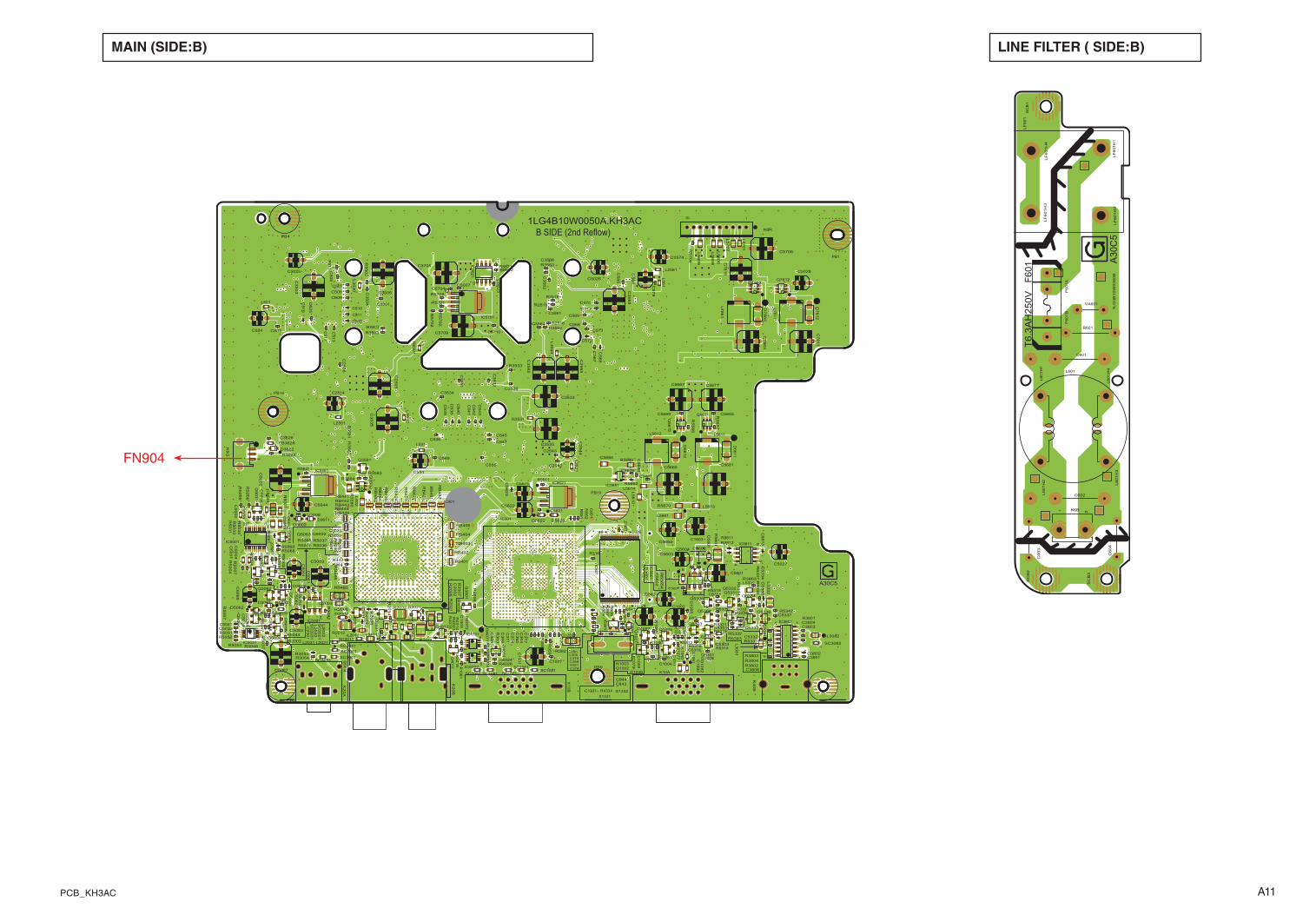
A11PCB_KH3AC
B SIDE (2nd Reflow)1LG4B10W0050A.KH3AC
K10A
K1
0B
K3
0B
110
K8R
K2
0A
K20
B
K40B
D3611
R3801
R3802
R3803R3804
85
14
IC8811
R3
80
6
1
89
16
IC3801
R8821R8822 L2561
D3622
85
14
IC8
82
1
R3622
R804
Q401
1
Q4012
R807
Q4
01
4
R808
R3053R3054
C1331 C1332
RB
48
1
RB
48
2
RB
48
3R
B4
84
RB485
RB
48
6
L5661
L3
53
0
R442
L3
53
2
L3
53
3
R444
R4
01
4
R4
01
6
R4017
C1353
R1331
R4
02
3
R4024
C8
01
PB1
R4026
PB4
PB8
PB9
R8
46
C4057
C2
50
5
C2
50
6
C5
00
1
R8
51
C5
00
2
R8
52
C5003
C5
00
4
SC1051
C5
00
6
C5007
C5008
C5
00
9
C2514
C5011
C5
012
C5
013
C5
01
4
SC1061
31K6G
R2
50
1
C5
02
4
SC2011
C5601
SC1071
C5025
C5602
C5026
C5027
C5603
C5028
C5604
R5
001
R5
00
2
C5607
R5
00
3
R5
00
4
R5
00
5
C841
C2535
R5
00
6
C842
R5
00
7
C843C844
110
20 11
IC5001
C5031
C5032
C5033
SC
2021 L2011
Q5
03
1
SC1081
L2012
Q5032
R2516
Q5
03
3
C5
03
7
Q5034
C5
03
8
R2518
Q5611
C5
03
9
R2519
R4
07
2
Q5
61
2
Q5
03
6
C2542
C2543
C2
54
4
C8
51
C3626
R4
07
7
C5041
C5621
L2021
SC1091
L305
SC
2031
C5622
L2
02
2
C5
62
3
R5
21
4
D5
60
1
R5
21
6
R5
60
1
L501
R5
60
2
L7811
R2531
1 3
45
IC5
60
1
IC401
L2031SC2041
L2
03
2
D5611
R5
03
1
C3501
D5
61
2
R5
03
2
R5
03
3
C3
50
3
R5
03
4
C3
50
4
C3505
C2
56
5
R5611
R5036
C3506
R5037R5039
C5
06
1
14 5
8
IC5031
SC2051
Q5
06
1
Q5062
Q5063
C5644
Q5
06
4
R5
04
0R
50
41
C5
06
9
D5622
R5042
D5623
R5044
C2574
2548
1 24
IC801
R5046
R5
04
7
R5
04
8
C100
1
IC5621
SC3001
L5
70
1
C1002
L5
70
2
C1
00
3
C1004
C5655
C1
00
5
Q1001
R5051
Q1002
R5052
C1007
R5053
C1008
Q1005
C1
00
9
L531
Q10
07
C5
08
1
C5
08
2
R3
50
2
C5083
R3503
C1010
C5
08
4
C101
1
D5061
C5661
D5062
C5087
C101
4
C5664
R5
06
1
C3
53
1
C5666
R5062
C3
53
2 C5667
R5
06
3
C3533
R5
06
4
C3534
C5669
D8
41
L5331
R5641
C3
53
5
R5066
L5
33
2
C3536
R5
06
7
R5068
R5069
C5670
C5671
R5071
C5676
R5
65
2
R1003
L7
86
1
R316
C5
68
0
C5681
FB3626
C5684
IC5461
R5
11
R5
08
2
R5660
IC841
L5
61
1 3
45
IC5081R
56
66
R3533
C3561
C3
56
2
C3
56
3
C3564
X1331
C3
56
5
C3566
R5679
SC3051
R5680
R1036
R1
03
8
IC5681
C2
00
1
C2
00
2
C2003
C503
C5
06
C507
R1
04
0
C508
C509
Q3581
Q3
58
2
R3
55
R3562
R3563
R1
048
C510
R3
59
C511
C512
C5
13
C320
Q201
1
C5
17
R1050
R361
C5
19
R3
638
5
41 IC4701
SC
3081
SC3082
C524
Q2021
C5
25
D2002
R1
06
0R2002
R3
58
0R
35
81
R2006
R3
58
2
R2
00
7
C7
81
3
R3583
R3584
R1
06
9
L3
08
1
C1
09
2
C7
81
6
L3082
Q7812
Q2
03
1
C536
R10
70
C5
38
R2011
C5
39
R2012
R382
C5303
Q5301
Q5302
R2
01
6
Q5303
R1
07
7
Q5304
C5
40
R1
07
9
C5
41
Q5306
C5
42
C5
43
C545
C547
R20
21
R1081
C549
R2
02
2
C358
R2
02
6
C5318
D7
81
2
C554
C5704
D1091
C5705
C555
D1
09
2
C5706
C3
64
C3
65
C5709
C3
66
R2032
C3
68
R2
03
4R2
03
6
PB14
C5710
PB15
R5303
RB401
C3
71
RB402
C5
66
RB403
C5
67
C3
74
RB404
C568
C5331
L2501
C569
RB406
8
5
41
IC5302
C5332
C3
77
C378
C5
33
4
C379
Q5331
L402
Q5332
C5
33
6
Q5333
C5337
Q5334
C570
C571
R5312
Q5336
C572
R5313
C573
R5314C381
IC301
R5316
R5318
R5319
C5
79
R5701
R5
70
2
R5
70
3
R5
70
4
R5705
C7
86
3
R5321
IC5701
Q7862
C5
84
RB
42
1
C5
85
RB
42
2
RB
42
3
R5
56
54
RB
42
4
RB
42
6
C8
813
C3801
R5331
C3802
R5332
C3803
R5333
C3804
R5
33
4
Q3
80
1
C3806
R5336
R5
33
7R
53
38
L2
53
1
L5
60
6
L5
60
8
L5
60
9
C8
82
3
D7
86
2
R5342
R5343
L5
61
0
RB441
L5611
RB442
L5612
L5613RB443RB444
L5614
D3
60
1
D3602
RB446
D3606
R3603
R8811R8812
A30C5
+
+
+
MAIN (SIde:B)
FN904
LINe FILter ( SIde:B)
F6
01
T6
.3A
H2
50
V
1LG
4B
10W
0060B
R601
C601
C602
1 2K6B
SC
B1
SC
B2
SC
B3
F601
AF
601
B
L601
VA601
C604
C603
LF
60
1
LF
601H
3
L601H
3
LF
601H
4
LF
601H
2
L601H
4
L601H
1
LF
601H
1
L601H
2
A30
C5

A1� PCB_KH3AC
NO DATA
Related Documents