CONTROLING OF MOBILE AGENTS USING INTELLIGENT STRATEGY AN INTERIM REPORT SUBMITTED IN PARTIAL FULFILLMENT OF THE REQUIREMENTS FOR THE DEGREE OF Bachelor of Technology In Mechanical Engineering By Sanmay Satpathy (ROLL.NUMBER: 10503038) Under The Guidance of Prof D.R.K.Parhi Department of Mechanical Engineering National Institute of Technology Rourkela 2008-09

Welcome message from author
This document is posted to help you gain knowledge. Please leave a comment to let me know what you think about it! Share it to your friends and learn new things together.
Transcript
CONTROLING OF MOBILE AGENTS USING
INTELLIGENT STRATEGY
AN INTERIM REPORT SUBMITTED IN PARTIAL
FULFILLMENT OF THE REQUIREMENTS FOR THE
DEGREE OF
Bachelor of Technology
In
Mechanical Engineering
By
Sanmay Satpathy (ROLL.NUMBER: 10503038)
Under The Guidance of
Prof D.R.K.Parhi
Department of Mechanical Engineering
National Institute of Technology
Rourkela
2008-09
1
National Institute of Technology
Rourkela
CERTIFICATE
This is to certify that the project entitled, “Controlling of an
Agent using Intelligent Strategy” submitted by Sanmay Satpathy in
partial fulfilment of the requirements for the award of Bachelor of
Technology, Rourkela (Deemed University) is an authentic work
carried out by him under my supervision and guidance.
To the best of my knowledge, the matter embodied in the
project has not been submitted to any other University / Institute for
the award of any Degree or Diploma.
Date: Dr.D.R.K.Parhi
Dept. of Mechanical Engineering
National Institute of Technology
Rourkela – 769008
Signature: India

2
National Institute of Technology
Rourkela
ACKNOWLEDGEMENT
I would like to articulate my deep gratitude to my project guide
Prof.D.R.K.Parhi for their valuable guidance, immense motivation
and the kind of help to complete the project.
An assemblage of this nature could never have been attempted
without reference to and inspiration from the works of others whose
details are mentioned in reference section. I acknowledge my
indebtedness to all of them.
Last but not the least to all of my friends, who patiently extended
all sorts of help for accomplishing this undertaking.
Date: Sanmay Satpathy
Dept. of Mechanical Engineering
National Institute of Technology
Rourkela – 769008
Signature: India
3
Sl.No Topic Page
1. Certificate 1
2. Acknowledgement 2
3. Contents 3
4. Abstract 4
5. Chapter 1: Introduction
1.1 Objective
1.2 Navigation
1.3 Robotics
1.4 Mobile Robot
1.5 Intelligent Strategy
5-9
6. Chapter 2: Literature Survey 10-24
7. Chapter 3: WORK ANALYSIS
3.1 Algorithm of The Programme
3.2 My First Programme
3.3 Obstacles and The Arena
3.4 Final Programme
3.5 Results
25-71
8. Chapter 3: Conclusion 72-73
9. Reference 74-76
4
ABSTRACT
Robots are developed to carry out certain task to help the human
beings. A robot carrying out a particular needed task has promising
applications for the betterment of human society. So the control of
their motion remains a vital part for a robot.
In this project, I have to develop the simulation of mobile agents
(robots) in an arena of obstacles from a start point to a destination
point without collision. So in a way this project deals with successful
navigation of robots in prior known environment.
This document presents a computer vision method and related
algorithms for the navigation of a robot in a static environment. Our
environment is a simple white coloured area with coloured obstacles
(circle with white colour, rectangles with orange colour, triangle with
green colour and hexagon with pink colour which helps in identifying
the obstacle) and robot is in a rectangular form. The agents starting
point is in blue colour and the destination point is in red colour. This
environment is input by the user with the starting point and the
destination point. The data acquired from here is then used as an input
for the program which controls the robot drive motion in graphic
control window. Robot then tries to reach its destination avoiding
obstacles in its path. The algorithm presented in this paper uses the
distance transform methodology to generate paths for the robot to
execute which are written in C++ compiler. These paper
developments can also be applied to vehicles for collision free
driving.
5
Chapter 1
INTRODUCTION
1.1 Objective
1.2 Navigation
1.3 Robotics
1.4 Mobile Robots
1.5 Intelligence Strategy
6
INTRODUCTION
We know that we can make robot working and carry out
assign task successfully with a little help in programming.
1.1 OBJECTIVE: The main scientific objective of the project is
to add intelligence into robot artificial by using programming
software.
1.2 NAVIGATION: The term navigation means the process of
planning and directing the route or course of a robot or a vehicle.
1.3 ROBOT: A robot is an electro-mechanical device that can
perform autonomous or pre-programmed task. A robot may act as
under the direct control of human or autonomously under the control
of a programmed computer. Robots may be used to perform tasks that
are dangerous or difficult for humans to implement directly (e.g.
nuclear waste cleanup), or may be used to automate repetitive tasks
that can be performed with more precision by a robot than the
employment of a human (e.g. automobile production).
Robots may be controlled directly by a human, such as remotely
controlled bomb disposal robots, robotic arms, or shuttles, or may act
according to their own decision making ability, provided by Artificial
Intelligence. However, the majority of robots fall between these
extremes, being controlled by pre-programmed computers. Such
robots may include feedback loops such that they can interact with
their environment, but do not display actual intelligence.
7
1. 4 MOBILE ROBOTS: Mobile Robotics is an emerging field
of robotics that studies the behaviour of robots under dynamic and
challenging conditions to achieve its goal.
Mobile Robotics successfully incorporates all the constraints
that the robot experiences in its due course of operation and induces
behaviour of self-thinking to the robot by harnessing the power of
optimisation and intelligent techniques like Artificial intelligence,
Fuzzy-Logic, etc.
Mobile robots present special challenges. These robots can
move their bodies around from place to place. Why is this capability
difficult? Many more things can go wrong if your robot is free to
move around rather than being bolted to one place. Being mobile
multiplies the number of situations your robot needs to be able to
handle.
Mobile robots actually come in two varieties: tethered and
autonomous. A tethered robot "cheats" by dumping its power supply
and brain overboard, possibly relying on a desktop computer and a
wall outlet. Control signals and power are run through a bundle of
wires (the tether) to the robot, which is free to move around, at least
as far as the tether will allow.
Autonomous mobile robots are even more challenging. These robots
need to bring everything along with them, including a power supply
and a brain. The power supply is typically an array of batteries, which
adds a lot of weight to the robot. The brain is also constrained because
it has to fit on the robot, not weigh a ton, and be frugal about sucking
power out of the batteries.
8
1.5 INTELLIGENCE STRATEGY: Intelligence Strategy
making is a part of Artificial Intelligence (AI) technology which
provides techniques for developing computer programs for carrying
out a variety of tasks, simulating the intelligent way of problem
solving by humans. The problems that humans solve in their day-to-
day life are of a wide variety in different domains. Though the
domains are different and also the method, AI technology provides a
set of formalisms to represent the problems and also the techniques
for solving them. In this intelligent strategy making we have to plan
the path for autonomous robot by programming. Different people
working in this topic for many years have proposed different
definitions. According to Rich, Intelligent strategy is the study of how
to make computers do things at which humans are better at. It is
observed that it is equally difficult to define human intelligence.
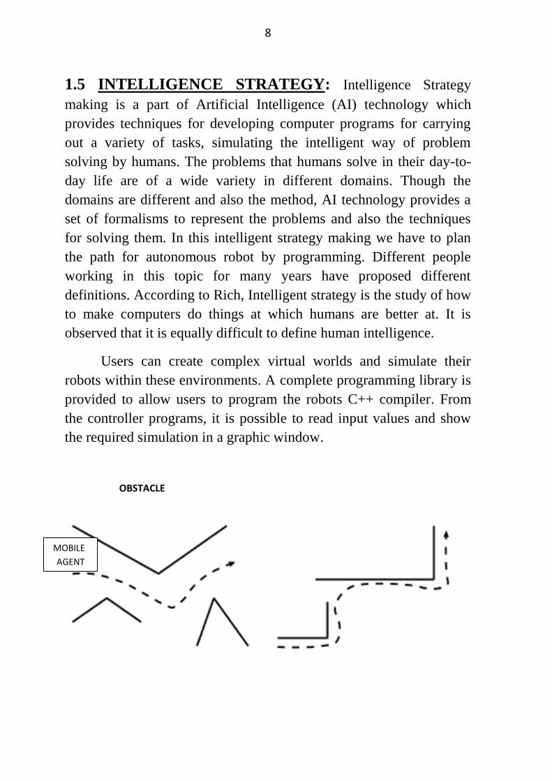
Users can create complex virtual worlds and simulate their
robots within these environments. A complete programming library is
provided to allow users to program the robots C++ compiler. From
the controller programs, it is possible to read input values and show
the required simulation in a graphic window.
MOBILE
AGENT
OBSTACLE
9
C++ Compiler
It provides an environment for programming. Due to
its functions and syntaxes it more versatile and faster programming
language. It is very popularly used for writing the codes for artificial
intelligence. For bigger and complicated programs C++programming
software provides much more quicker results than other softwares.
The space consumption by this software is also quiet less. C++
compiler also provides very good hardware interfacing between
computer and machine (in this case robot).
Graphics Window
It is very crucial for the display of the output on the
window screen. Graphic is a tool to draw figure and set into then
required colours and patterns. In graphic window we can create
different obstacles set them colours also. The simulation of the
navigation is seen on a graphic window.
10
Chapter 2
LITERATURE SURVEY
11
LITERATURE SURVEY
Location estimation is essential for guidance of autonomous
vehicles in many indoor navigation applications. A widely adopted
approach is the vision-based technique. Most existing vision-based,
Wua[1] techniques deal only with frontal scenes acquired by
traditional cameras and are easily interfered by unexpected objects
around the vehicle. A feasible solution to this problem is to use an
omni-directional camera which looks upward at certain target shapes,
called landmarks usually, attached on the ceiling. This solution has
the unique advantage of providing wide-angle views with fewer
objects appearing in the field of view, thus reducing the guidance
error coming from landmark occlusion, noise inference, etc. This is
important for applications of intelligence robots such as cleaning
robots, pet robots, tour guide robots, etc., which must work among
humans or objects at close distances.
In order to test the effectiveness of the proposed location
estimation method a study has been made which includes two parts
(1)using computer simulations to test if the circular shape of the
landmark in the acquired images taken with omni-directional cameras
with different shapes of hyperboloidal mirrors can be detected by the
proposed ellipse approximation method; (2) using real images to
determine the precision of the estimated vehicle locations relative to
the landmark. For measurement of the estimation precision, we define
a distance error ratio and an orientation error as follows:
distance error ratio=(real distance-estimated distance)/(real distance) orientation error = real orientation-estimated orientation
So this new approach provides a way to location estimation of an
autonomous vehicle for navigation guidance in an indoor environment
using a circular-shaped landmark on the ceiling by omni-directional
vision techniques.
Cooperative behaviours, Parhi [2] using a colony of robots are
becoming more and more significant in industrial, commercial and
scientific application. Applications in the area of service robotics
12
demand a high degree of system autonomy, which robots without
learning capabilities will not be able to meet? Problems such as co-
ordination of multiple robots, motion planning and co-ordination of
multiple robotic systems are generally approached having a central
(hierarchical) controller in mind. Here by using Rule base technique and petri net modelling to
avoid collision among robots one model of collision free path
planning has been proposed. The second model incorporates rule
based fuzzy-logic technique and both the models are compared. It has
been found that the rule-based technique has a set of rules obtained
through rule induction and subsequently with manually derived
heuristics. This technique employs rules and takes into account the
distances of the obstacles around the robots and the bearing of the
targets in order to compute the change required in steering angle.
With the use of Petri net model the robots are capable of negotiate
with each other. It has been seen that, by using rule-based-neuro-
fuzzy technique the robots are able to avoid any obstacles (static and
moving obstacles), escape from dead ends, and find targets in a highly
cluttered environments. Using these techniques as many as 1000
mobile robots can navigate successfully neither colliding with each
other nor colliding with obstacles present in the environment. It was
observed that the rule-based-neuro-fuzzy technique is the best
compared to the rule-based technique for navigation of multiple
mobile robots.
A paper by Fainekos et al.[3] provides a tractable solution to the
RTL motion planning problem for dynamics models of mobile robots. Temporal logic motion planning problem for mobile robots are
modelled by second order dynamics. Temporal logic specifications
can capture the usual control specifications such as reach ability and
invariance as well as more complex specifications like sequencing
and obstacle avoidance. An automatic framework for the solution of
the temporal logic motion planning problem for dynamic mobile
robots has been presented here. The framework is based on
hierarchical control, the notion of approximate bisimulation relations
and a new definition of robustness for temporal logic formulas. In the
process of building this new framework two intermediate results have
13
been derived. First, an automatic framework for the solution of the
temporal logic motion planning problem for kinematic models has
been presented. Second, how to construct a more robust solution to
the above problem, which can account for bounded errors in the
trajectories of the systems has been shown. This paper presents the
first computationally tractable approach.
Temporal logics such as Linear Temporal Logic (LTL) (Pnueli,
1977) and its continuous time version propositional temporal logic
over the reals (RTL) (Reynolds, 2001) have the expressive power to
describe a conditional sequencing of goals under a well-defined
formal framework.
Such a formal framework can provide us with the tools for
automated controller synthesis and code generation. Beyond the
provably correct synthesis of hybrid controllers for path planning
from high level specifications, temporal logics have one more
potential advantage when compared to other formalisms, e.g., regular
languages (Koutsoukos, Antsaklis, Stiver, & Lemmon, 2000). That is
to say, temporal logics were designed to bear a resemblance to natural
language. Along the same lines, one can develop computational
interfaces between natural language and temporal logics (Kress-Gazit,
Fainekos, & Pappas, 2007). This fact alone makes temporal logics a
suitable medium for our daily discourse with future autonomous
agents.
Gurman has described in detail the neural network models
RuleNet and its extension. RuleNet is a feed forward network model
with a supervised learning algorithm, a dynamic architecture, and
discrete outputs. He has achieved results in the simulation and
experimental environment. Li et al. have presented neuro-fuzzy
system architecture for behaviour-based control of a mobile robot in
unknown environments. The simulation experiments show that the
proposed neuro-fuzzy system can improve navigation performance in
complex and unknown environments. Barfoot and Ibrahim have
discussed a newly developed adaptive fuzzy behavioural control
system. That has been designed for use with an autonomous mobile
robot. They have shown their results on both experimental and
industrial applications in which their new control system was applied.
14
Their results have shown that the robot can avoid simple obstacles
only. Experiment results done on a single mobile robot confirms their
technique. Jelena has considered a rule-based fuzzy controller and a
learning procedure based on the stochastic approximation method.
They have considered the radial basis function neural network and
have shown that a modified form of this network is identical with the
fuzzy controller, which they claim it as a neuro-fuzzy controller.
Acosta et al. have used a neuro-fuzzy technique to steer a mobile
robot. The results of the approach are satisfactory (i.e., avoiding the
obstacles when the mobile robot is steered to the target).Marichal et
al. have presented a neuro-fuzzy approach in order to guide a mobile
robot. They have shown that such a neuro-fuzzy system is successful
in the control of a single mobile robot only.
Althoefer et al. have reported a navigation system for robotic
manipulators. The navigation method is a combination of fuzzy logic
and neural networks. They successfully applied this technique to
robot arms in different environments. Nefti et al. have applied neuro-
fuzzy inference system for mobile robot navigation in partially
unknown environment. The experimental results confirm the
meaningfulness of the elaborated methodology when dealing with
navigation of a mobile robot in partially unknown environment.
Tunstel et al. have discussed operational safety and health monitoring
of critical matters for autonomous field mobile robots. de Souza and
Ferreira have proposed a reusable architecture for rule-based systems
described through design patterns. The aim of these patterns is to
constitute a design catalogue that can be used by designers to
understand and create new rule-based systems. A hybrid control
architecture combining behaviour-based reactive navigation and
model based environment classification has been developed by Na
and Oh. The effectiveness of the proposed architecture has been
verified through both computer simulation and an actual robot called
MORIS (mobile robot as an intelligent system). Dietrich et al. have
discussed a general architecture for rule-based agents and described
the method to realise the navigation control with the help of semantic
web languages. McIntosh et al. have described a simple „proof of
concept‟ rule- based system. They have developed to contribute
15
methodologically to management-oriented modelling of vegetated
landscapes. They have not specifically used rule-based technique for
navigation of mobile robot. Pradhan et al. have discussed about the
fuzzy control technique for navigation of robots.
Fraichard and Garnier, Abdessemed et al. used manually
designed fuzzy logic controller (FLC) for planning collision-free
motion of a car-like robot. As the performance of an FLC depends on
the selection of membership function distributions (known as
database) and its rule base (RB), some investigators tried to optimize
both the RB as well as database, either separately or simultaneously.
In this connection, the work of Song and Sheen, Li et al. are worth
mentioning. However, the effectiveness of their optimized FL-based
systems was studied in a static environment. In most of the fuzzy
control systems, fuzzy if–then rules were designed by human experts,
who may sometimes find it difficult to express their actions or may
decide on a subconscious level. Thus, some attempts were made by
Marichal et al., Pratihar and Bibel and others to develop the RB of the
FLC automatically, using an NN and/or a GA. Hui and Pratihar also
developed a method for automatic design of FLC, inwhich the whole
task of designing it, was given to a GA. The GA evolves a suitable
knowledge base (KB) of that FLC through the interactions between
the robot and the environment.
The main advantage of this method lies in the fact that the designer
may not need to have a complete knowledge of the problem to be
solved. Moreover, the entire optimization process is normally carried
out off-line and once trained, the FLC might be suitable for on-line
implementations.
NNs had also been used by some investigators for solving the
said problem. In this connection, work of Yang and Meng, Floreano
and Mondada , Pal and Kar , Gu and Hu are important to mention.
However, the performance of an NN depends on its architecture and
connecting synaptic weights, the optimal selection of which is a
tedious job. A variety of tools, namely supervised and reinforcement
learning algorithms, back propagation algorithm, simulated annealing
(SA), genetic programming (GP), GA were utilized by some
researchers for the said purpose.
16
Zielin[4] et al taking into account the utilised principle of
communication two extreme classes of multi-robot (multi-agent)
systems exist. The first category uses explicit communication, where
the robots communicate directly between themselves (e.g., using
wireless or network technology). The second category uses implicit
communication, where each robot observes the actions of the others
or the results of their activity in the environment (i.e., stigmergy). In
the former case the problem at hand is subdivided into tasks. In the
latter case, rather than decomposing the problem into tasks,
investigations focus on the definition of elementary behaviours of
individuals. The approach to the design of those categories of systems
differs considerably. The first relies on task decomposition (this
results in a top down approach) while the second relies on the
definition of elementary behaviours and lets them interact freely (this
produces a bottom up approach) – in this case the resultant behaviour
of the system emerges as a consequence of those interactions.
Between those extremes spreads the realm of hybrid systems utilising
both implicit and explicit communication mechanisms.
Explicit communication usually requires problem decomposition
into tasks and subsequently allocation of those tasks to robots. The
task allocation problem depends on the requirements of the tasks and
the capabilities of robots. Hence the tasks and robots are subdivided
into categories. Tasks can either be executed by single robots, thus SR
tasks, or need many robots, thus multiple-robot (MR) tasks. The
robots can either execute a single task at a time (i.e., ST robots) or
several tasks simultaneously (i.e., MT – multiple task robots).
Moreover, all tasks to be executed can be known in advance – this
produces an instantaneous assignment (IA) problem, or the tasks can
appear randomly as the time passes – this results in time-extended
assignment (TA). In the former case no planning for the future is
necessary, while in the latter case future requirements have to be
taken into account. If there are more tasks than robots or vice versa
optimal allocation of tasks requires some criterion of judging the
result. Usually utility is defined as a difference between quality of the
17
obtained result and the cost of producing it. In the simplest case utility
depends only on the robot and the task it has to execute. However,
utility might also depend on the sequence of task execution, number
of robots executing the task, other tasks that the robot has already
executed, the tasks that the other robots have executed etc.
Implicit communication is used to solve a wide variety of
problems, e.g., path planning, object sorting, building structures, self-
assembly, cooperative transport, surveillance, prey hunting. Many of
such systems are biologically inspired – frequently they rely on
mimicking insect social behaviour. Social insects (i.e., insects living
in colonies, e.g., ants, bees, wasps, termites) draw our attention,
because each insect exhibits simple behaviour, yet the colony as a
whole produces useful and complex output. Thus limited perceptual
and cognitive capabilities, through mutual interactions, both between
the individuals and between an individual and the environment, result
in attaining a complex goal. This is termed as emergent behaviour.
The attractiveness of emergent behaviour, where individual
elementary behaviours are simple and the communication is limited to
individual‟s perception, is even more underscored by the fact that
explicit communication faces a scaling problem which is absent in the
implicit case. In the explicit case with the increase of the number of
robots the organisation of communication between them becomes
ever more difficult. On the other hand, although implicit
communication systems tend to be robust (immune to the failure of
some individuals or changes in the environment), the emergent result
is difficult to predict, hence program. The difficulty arises from the
fact that the result is not only based on each individual‟s behaviour,
but also on the interactions between them and the environment, which
are hard to foresee.
In some cases, as the individuals do not have the knowledge
about the global goal, this can lead to stagnation (deadlock).
However, the advantages of those systems prevail over their
disadvantages, if only the above disclosed drawbacks are dealt with
appropriately. Although in reality it will be probably necessary to
design hybrid systems, it is important to find out to what extent they
18
can rely on autonomous behaviour of individual agents. The greater
the extent of autonomy of an agent the more robust will the system as
a whole be. Especially the immunity to failure of individuals will be
greatly enhanced.
Thus this paper mainly focuses on the method of defining and
implementing behaviours of individual agents neglecting to a large
extent the benefits of explicit communication. However, the presented
method of defining autonomous activity of agents is elaborated in
such a way that behaviours can also utilise information communicated
to them directly by the other agents.
Bio-inspired[5] vision system is a particularly good candidate for
navigation of mobile robots and vehicles because of its computational
advantages, e.g., low power dissipation and compact hardware.
Previously, we had designed a mixed analog�digital integrated vision
system for collision detection inspired by a locust neuronal circuit
model. The response of the system was, however, susceptible to the
luminance of approaching objects and the vibratory self-motion of a
car when it was installed on a miniature mobile car. In the present
study, we developed a new collision detection algorithm to overcome
these problems based on robust image-motion detection and applied
the algorithm to control a miniature mobile car.
Visually guided real-time collision avoidance requires expensive
computation of the conventional machine vision systems comprising
charge-coupled device (CCD) cameras and digital processing systems
operating with serial algorithms. In this regard, the bio-inspired vision
systems are suitable for navigation of autonomous robots because of
their highly efficient computation of visual information.
Bio-inspired algorithms for collision avoidance, mimicking the
response of the lobula giant movement detector (LGMD) of locusts,
have been implemented on a personal computer as well as a digital
very large-scale integrated (VLSI) vision chip based on a neural
circuit model proposed by Rind and Bramwell.
19
In this case designed a model with parallel computational
architecture inspired by the LGMD neuron and implemented it with a
compact hardware system comprising a resistive network and field-
programmable gate array (FPGA) circuits so as to take advantage of
the real-time analog computation and programmable digital
processing. This system computes image expansion in real time using
an analog resistive network in order to detect approaching objects.
This mixed analog digital model is designed to minimize proliferated
wirings between neural layers, which communicate with the
duplicated connection pattern in the original model, and therefore, can
achieve real-time computation with a high computational efficiency.
The system responded to virtual approaching objects, which were
created on a computer and presented on a liquid crystal display (LCD)
monitor, only at close range. The response of the system was,
however, susceptible to the luminance of approaching objects and the
vibratory self-motion of a car when it was installed on a miniature
mobile car in real-world situations.
In this work, we are particularly interested in the action
selection and coordination for joint multi-robot tasks, motivated by a
prototype environment of robot soccer[6]. We have successfully
applied Case-Based Reasoning (CBR) techniques to model the action
selection of a team of robots within the robot soccer domain.
However, our previous approach did not address the dynamic
intentional aspect of the environment, in particular, in robot soccer,
the presence of adversaries. Many efforts aim at modelling the
opponents in particular when the perception is centralized. Instead, we
address here a robot soccer framework in which the robots are fully
distributed, without global perception nor global control, and can
communicate.
We follow a CBR approach where cases are recorded and model
the state of the world at a given time and prescribe a successful action
A case can be seen as a recipe that describes the state of the
environment (problem description) and the actions to perform in that
state (solution description). Given a new situation, the most similar
past case is retrieved and its solution is reused after some adaptation
20
process to match the current situation. We model the case solution as
a set of sequences of actions, which indicate what actions each robot,
should perform. Our case-based approach is novel in the sense that
our cases represent a multi-robot situation where the robots are
distributed in terms of perception, reasoning, and action, and can
communicate. Our case-based retrieval and reuse phases are therefore
based on messages exchanged among the robots about their internal
states, in terms of beliefs and intentions.
Our case representation ensures that the solution description in
the cases indicates the actions the robots should perform; that the
retrieval process allocates robots to actions; and finally, with the
coordination mechanism, that the robots share their individual
intentions to act. Our approach allows for the representation of
challenging rich multi-robot actions, such as passes in our robot
soccer domain, which require well synchronized positioning and
actions.
The results obtained both in simulation and with the real robots,
confirm that the Case-Based Reasoning approach is better than the
reactive approach, not only on placing a higher percentage of balls
close to the opponent‟s goal, but also achieving a lower percentage of
out balls. More precisely, the results obtained in the third scenario
with the real robots confirms the simulation results. In the fourth
scenario, once again the average of balls out is higher for the reactive
approach, which confirms that the defence had more chances to steal
the ball.
Hui[7] et al. had made a comparative study of various robot
motion planning schemes has been made in the present study. Two
soft computing (SC)-based approaches, namely genetic-fuzzy and
genetic-neural systems and a conventional potential field method
(PFM) have been developed for this purpose. Training to the SC-
based approaches is given off-line and the performance of the optimal
motion planner has been tested on a real robot. Results of the SC-
based motion planners have been compared between themselves and
with those of the conventional PFM. Both the SC-based approaches
are found to perform better than the PFM in terms of travelling time
21
taken by the robot. Moreover, the performance of fuzzy logic based
motion planner is seen to be comparable with that of neural network-
based motion planner.
Comparisons among all these three motion planning schemes
have been made in terms of robustness, adaptability, goal reaching
capability and repeatability. Both the SC-based approaches are found
to be more adaptive and robust compared to the PFM. It may be due
to the fact that there is no in-built learning module in the PFM and
consequently, it is unable to plan the velocity of the robot properly.
Building an autonomous and intelligent robot that requires minimal or
no human interactions, has become a thrust area in robotic research. It
should have a real-time sensing assembly, an intelligent decision
maker and precise actuators. The present paper deals with design and
development of adaptive motion planner of a car-like robot navigating
among some moving obstacles. Both algorithmic as well as soft
computing (SC)-based approaches of robot motion planning were
developed by various investigators [8]. Latombe [9] provides an
extensive survey on various algorithmic methods of robot motion
planning. A large number of algorithmic approaches, such as tangent
graph [10], path velocity decomposition method [11], accessibility
graph [12], space–time concept [13], incremental planning [14],
relative velocity approach [15], potential field method (PFM) [2],
reactive control scheme [16], curvature-velocity method [17],
dynamic window approach [18], randomized kinodynamic planning
[19] are available in the literature. However, these algorithmic
approaches suffer from the following drawbacks: (i) not all the
approaches are computationally tractable and thus, they may not be
suitable for on-line implementations, (ii) one method may be suitable
for solving a particular type of problem and no versatile technique is
available, (iii) most of the approaches do not have any in-built
optimization module and as a result of which, the generated path may
not be optimal in any sense. Out of all the algorithmic approaches,
PFM is found to be the most popular one, due to its elegant
mathematical analysis and simplicity. However, it has the following
disadvantages [20]: (i) it may not be able to yield local minima-free
path, when the robot navigates among concave obstacles, (ii) it may
not find any feasible path for the robot, when it moves among closely
22
spaced obstacles, (iii) a dead-lock situation may occur, when the
attractive potential balances the repulsive potential. Several modified
versions of the PFM are also available in the literature. Interested
readers may refer to for the same. However, none of these methods
could plan the motion of the robot in an optimal way, as there is no
in-built optimization module in it.
Ahuactzin et al.[21] has formulated a genetic algorithm for
motion planning of robots which shows that the path planning
problem can be expressed as an optimization problem and thus solved
with a genetic algorithm. We illustrate this approach by building a
path planner for a planar arm with two degree of freedom, and then
we demonstrate the validity of the method by planning paths for a
holonomic mobile robot.
The ability to acquire a representation of the spatial environment
and the ability to localize within it are essential for successful
navigation in a-priori unknown environments[22] .This paper briefly
reviews the relevant neurobiological and cognitive data and their
relation to computational models of spatial learning and localization
used in mobile robots. The resulting model allows a robot to learn a
place-based, metric representation of space in a-priori unknown
environments and to localize itself in a stochastically optimal manner.
Autonomous Cross-Country Navigation[23] requires planning
algorithms which supports rapid traversal of challenging terrain while
maintaining vehicle safety. The planning system uses a recursive
trajectory generation algorithm, which generates spatial trajectories
and then heuristically modifies them to achieve safe paths around
obstacles. Velocities along the spatial trajectory are then set to ensure
a dynamically stable traversal.
In this paper we describe a robot path planning algorithm that
constructs a global skeleton of free-space[24] by incremental local
methods. The curves of the skeleton are the loci of maxima of an
artificial potential field that is directly proportional to [the] distance of
23
the robot from the obstacles. Our method has the advantage of fast
convergence of local methods in uncluttered environments, but it also
has a deterministic and efficient method of escaping local external
points of the potential function.
In a paper, Cherif [25] we address the problem of motion
planning for a mobile robot moving on a hilly three dimensional
terrain, and subject to dynamic and physical interaction constraints. A
mixed planning method based upon a two-level approach combining a
discrete search strategy operating on a subset of the configuration
space of the robot, and a continuous motion generation technique
considering the kinematic and dynamic constraints of the task.
Najera[26] et al. presents an approach to plan motion strategies
for robotics tasks constrained by uncertainty in position, orientation
and control. Our approach operates in a (x, y, theta) configuration
space and it combines two local functions: a contact-based attraction
function and an exploration function. Compliant motions are used to
reduce the position/orientation uncertainty. An explicit geometric
model for the uncertainty is defined to evaluate the reachability of the
obstacle surfaces when the robot translates in free space.
The path planning problem for arbitrary devices[27] is first and
foremost a geometrical problem. For the field of control theory,
advanced mathematical techniques have been developed to describe
and use geometry. In this paper, we use the notations of the flow of
vector fields and geodesics in metric spaces to formalize and unify
path planning problems. A path planning algorithm based on flow
propagation is briefly discussed. Applications to the theory to motion
planning for a robot arm, a maneuvring car, and Rubik's Cube are
given. These very different problems (holonomic, non-holonomic and
discrete, respectively) are solved by the same unified procedure.
Egbert et al.[28] present a technique for automatically providing
animation and collision avoidance in a general-purpose computer
graphics system. The technique, which relies on an expanded notion
24
of vector fields, allows users to easily set up and animate objects, then
prevents objects from colliding as the animation proceeds.
LaValle[29] et al. introduces a visibility-based motion planning
problem in which the task is to coordinate the motions of one or more
robots that have omni-directional vision sensors, to eventually "see" a
target that is unpredictable, has unknown initial position, and is
capable of moving arbitrarily fast. A visibility region is associated
with each robot, and the goal is to guarantee that the target will
ultimately lie in at least one visibility region. A complete algorithm
for computing the motion strategy of the robots is also presented.
Zelinsky[30] presents an algorithm for path planning to a goal
with a mobile robot in an unknown environment. The robot maps the
environment only to the extent that is necessary to achieve the goal.
Paths are generated by treating unknown regions in the environment
as free space. As obstacles are encountered en route to a goal, the
model of the environment is updated and a new path to the goal is
planned and executed. The algorithm presented in this paper makes
use of the quadtree data structure to model the environment and uses
the distance transform methodology to generate paths for the robot to
execute.
Jönsson[31] describes an algorithm for approximately finding the
fastest route for a vehicle to travel between two points in a digital
terrain map, avoiding obstacles along the way. The enemies are
avoided by staying out of their line of sight. However, the general
results of this paper should be feasible for a much wider range of
applications ranging from complex GIS [Geographic Information
Systems] systems to home computer games. The approach taken in
this work is to translate the problem into a least cost path graph
problem with an associated cost function on the graph edges.
25
Chapter 2
CURRENT WORK DONE
1. Algorithm of The Programme
2. My First Programme
3. Obstacles and The Arena
4. Final Programme
26
3.1 WORK ANALYSIS
Algorithm of Path Planning of Mobile Robots: User will be asked to input the type of obstacle .Depending on
the type of obstacle number of sides if it is a polygon.
Then depending on the type of obstacle it asks to enter the co-
ordinate of the vertices if it is a polygon and the co-ordinate of
centre and the radius if it is a circle.
User has the flexibility to add any number of obstacles in the
arena. The arena has a co-ordinate system which ranges from 0
to 700 in the horizontal axis (x-axis) and from 0 to 500 in the
vertical axis(y- axis).
After inserting the obstacles it will ask to enter the starting point
and the destination point of the mobile agent.
In the programme the starting point co-ordinates are taken as a
and b and the destination point is taken as(x1, y1).
For shortest distance path the robot has to travel to the
destination along a straight line. So the slope of the line joining
(a, b) and (x1, y1) is mo=(y1-b)/(x1-a). The equation of the
line in which the robot has to move: yi=(mo)*(xi-a)+b.
Now “for loop” for the programme will be start incrementing
the value of xi by1 and getting the value of yi from the above
mentioned equation.
According to the value of the co-ordinates given to the obstacles
the equation and the range of their side or curves are obtained.
While the “for loop” is running the values of xi and yi were
continuously being checked with the equations of sides or
curves (circle) of the obstacles.
If the value of xi and yi satisfies the preset values of equation
then the robot will move till the end point of that side with the
same slope as that of side in order to avoid collision.
27
3.2 My First Program:
#include <graphics.h>
#include <stdlib.h>
#include <stdio.h>
#include<iostream.h>
#include <conio.h>
#include<dos.h>
#include<math.h>
void main()
{
int x1,y1,a=30,b=450;
int
ans=1,a1=0,b1=0,a2=0,b2=0,a4=0,b4=0,a5=0,b5=0,a6=0,b6=0;
line4: if(ans==2)
{
int
k,a11=152,b11=330,a12=120,b12=110,a14=317,b14=87,a15=5
20,b15=205,a16=490,b16=470;
int cas1;
line1: cout<<"if you want to change triangle 1 enter1 , to change
rectangle 1 enter 2, to change the circle enter3, to change
triangle2 enter 4, to change rectangle2 enter 5, to change
rectangle3 enter 6\n";
cin>>k;
a=30;
b=450;
switch(k)
{
case 1:
{
cout<<"Enter the new centriod in x,y currently(152,330)\n";
cin>>a11>>b11;
a1=a11-152; b1=b11-330;
break;
}
28
case 2:
{
cout<<"Enter the new centriod in x,y currently(120,110)\n";
cin>>a12>>b12;
a2=a12-120; b2=b12-110;
break;
}
case 3:
{
cout<<"Enter the new centriod in x,y currently(280,210)\n";
// cin>>a13>>b13;
// a3=a13-280; b3=b13-210;
break;
}
case 4:
{
cout<<"Enter the new centriod in x,y currently(317,87)\n";
cin>>a14>>b14;
a4=a14-317; b4=b14-87;
break;
}
case 5:
{
cout<<"Enter the new centriod in x,y currently(520,205)\n";
cin>>a15>>b15;
a5=a15-520; b5=b15-205;
break;
}
case 6:
{
cout<<"Enter the new centriod in x,y currently(490,470)\n";
cin>>a16>>b16;
a6=a16-490; b6=b16-470;
break;
}
}
29
cout<<"Do you want to make subsequent changes if yes enter 1
otherwise enter 2";
cin>>cas1;
if(cas1==1)
{
goto line1;
}
if(cas1==2)
{
goto line3;
}
}
line3: cout<<"Set the target point";
cin>>x1>>y1;
clrscr();
/* request auto detection */
int gdriver = DETECT, gmode, errorcode;
/* initialize graphics mode */
initgraph(&gdriver, &gmode, "c:\\tc\\bgi");
/* read result of initialization */
errorcode = graphresult();
if (errorcode != grOk) /* an error occurred */
{
printf("Graphics error: %s\n", grapherrormsg(errorcode));
printf("Press any key to halt:");
line(5, 5, 30, 30);
getch();
exit(1); /* return with error code */
}
//instruction for drawing a hexagon//
int poly[14],tr1[7],tr2[7],r1[9],r2[9],r3[9];
poly[0]=480;
30
poly[1]=300;
poly[2]=532;
poly[3]=330;
poly[4]=532;
poly[5]=390;
poly[6]=480;
poly[7]=420;
poly[8]=428;
poly[9]=390;
poly[10]=428;
poly[11]=330;
poly[12]=poly[0];
poly[13]=poly[1];
drawpoly(7,poly);
// instruction for drawing a triangle 1//
tr1[0]=170+a1;
tr1[1]=230+b1;
tr1[2]=240+a1; tr1[3]=380+b1; tr1[4]=45+a1; tr1[5]=380+b1;
tr1[6]=tr1[0];
tr1[7]=tr1[1];
drawpoly(4,tr1);
//instruction for drawing rectangle 1 //
r1[0]=50+a2; r1[1]=40+b2; r1[2]=190+a2; r1[3]=40+b2;
r1[4]=190+a2; r1[5]=180+b2; r1[6]=50+a2; r1[7]=180+b2;
r1[8]=r1[0];
r1[9]=r1[1];
drawpoly(5,r1);
//instruction for drawing a circle//
// circle(280+a3, 210+b3, 60);
// instruction for drawing a triangle 2//
tr2[0]=300+a4;
tr2[1]=20+b4;
tr2[2]=400+a4, tr2[3]=120+b4, tr2[4]=250+a4, tr2[5]=120+b4;
tr2[6]=tr2[0];
tr2[7]=tr2[1];
drawpoly(4,tr2);
31
//instruction for drawing rectangle 2 //
r2[0]=440+a5, r2[1]=150+b5, r2[2]=600+a5, r2[3]=150+b5,
r2[4]=600+a5,r2[5]=260+b5, r2[6]=440+a5, r2[7]=260+b5;
r2[8]=r2[0];
r2[9]=r2[1];
drawpoly(5,r2);
//instruction for drawing rectangle 3 //
r3[0]=400+a6, r3[1]=450+b6, r3[2]=580+a6, r3[3]=450+b6,
r3[4]=580+a6,r3[5]=490+b6, r3[6]=400+a6, r3[7]=490+b6;
r3[8]=r3[0];
r3[9]=r3[1];
drawpoly(5,r3);
// line3: cout<<"Set the target point";
// cin>>x1>>y1;
// start of main program//
int i,y=0,p1;
for(i=30;i<=x1;i++) //
equation of line of travel//
{
line5: y=(((y1-b)*(i-a))/(x1-a))+b;
int w=0,m=0,s=0;
m=(y1-b)/(x1-a);
if(m>7)
{
s=10;
}
else
{
s=0;
}
if(i>40+a1 && i<171+a1) //for
triangle1
{
if(y>=(220+b1) && y<=(385+b1))
{
p1=y+(1.2*(i+7))-434-b1-(1.2*a1);
32
if(p1>=-15&&p1<=15)
{
if(y1>y)
{
outtextxy(i,y,"*");
}
else
{
if(y<=385+b1 && y>=225+b1)
{
y=434-(1.2*(i+7-a1))+b1;
{
outtextxy(i,y,"*");
w=1;
}
}
}
}
}
}
int p2;
if(i<=250+a1 && i>=170+a1)
{
if(y<=381+b1 && y>=220+b1)
{
p2=y-2.15*(i-240-a1)-380-b1;
if(p2<=20 && p2>=-20)
{
y=2.15*(i-240-a1)+380+b1;
outtextxy(i,y,"*");
w=1;
}
}
}
if(i>=40+a1 && i<=250+a1)
{
if(y>387+b1 && y<392+b1)
33
{
if(x1<120 && y1>250)
{
for(i=a;i>=25;i--)
{
outtextxy(i,y,"*");
w=1;
delay(40);
}
}
else
{
for(i=a;i<=250+a1;i++)
{
outtextxy(i,390+b1,"*");
w=1;
y=390+b1;
delay(40);
}
}
}
}
if(i>=39+a2 && i<=200+a2) // for rectangle1//
{
if(y>=30+b2 && y<=190+b2)
{
if(i==40+a2)
{
if(y<=189+b2)
{
for(y=b;y>=30+b2;y--)
{
w=1;
outtextxy(40+a2,y,"*");
delay(40);
}
// break;//
34
}
}
}
}
if(i>40+a2)
{
if(y<192+b2+s && y>175+b2-s)
{
for(i=a;i<=195+a2;i++)
{
outtextxy(i,190+b2,"*");
y=190+b2;
w=1;
delay(40);
}
}
}
if(i>=39+a2 && i<=200+a2)
{
if(y>=32+b2-s && y<40+b2+s)
{
for(i=a;i<=200+a2;i++)
{
outtextxy(i,y,"*");
w=1;
delay(40);
}
}
}
if(y>30+b2 && y<190+b2)
{
if(i==195+a2)
{
for(y=b;y>=30+b2;y--)
{
outtextxy(i,y,"*");
w=1;
35
delay(40);
}
}
}
if(i>240+a4 && i<310+a4) //for triangle 4//
{
if(y<125+b4 && y>15+b4)
{
y=-(11/7)*(i-240-a4)+125+b4;
outtextxy(i,y,"*");
w=1;
}
}
if(i>=245+a4 && i<=410+a4)
{
if(y>125+b4-s && y<132+b4+s)
{
for(i=a;i<=410+a4;i++)
{
outtextxy(i,130+b4,"*");
w=1;
y=130+b4;
delay(40);
}
}
}
if(i==430+a5) // for rectangle 2//
{
if(y<270+b5 && y>=140+b5)
{
for(y=b;y>140+b5;y--)
{
outtextxy(430+a5,y,"*");
w=1;
delay(40);
36
}
}
}
if(i>435+a5 && i<605+a5)
{
if(y>260+b5 && y<270+b5)
{
if(x1<=605+a5)
{
outtextxy(i,y,"*");
w=1;
}
else
{
y=270+b5;
for(i=a;i<610+a5;i++)
{
outtextxy(i,y,"*");
w=1;
delay(40);
}
}
}
if(y>140+b5 && y<150+b5)
{
y=140+b5;
for(i=a;i<610+a5;i++)
{
outtextxy(i,y,"*");
w=1;
delay(40);
}
}
}
if(i==608+a5)
{
37
if(y<270+b5 && y>140+b5)
{
for(y=b;y>140+b5;y--)
{
outtextxy(i,y,"*");
w=1;
delay(40);
}
}
}
if(i==390+a6) //for rectangle3//
{
if(y<500+b6 && y>=440+b6)
{
for(y=b;y>440+b6;y--)
{
outtextxy(390+a6,y,"*");
w=1;
delay(40);
}
}
}
if(i>395+a6 && i<585+a6)
{
if(y>490+b6 && y<500+b6)
{
y=500+b6;
for(i=a;i<585+a6;i++)
{
outtextxy(i,y,"*");
w=1;
delay(40);
}
}
if(y>=440+b6 && y<450+b6)
{
if(x1<585+a6)
38
{
outtextxy(i,y,"*");
w=1;
}
else
{
y=440+b6;
for(i=a;i<585+a6;i++)
{
outtextxy(i,y,"*");
w=1;
delay(40);
}
}
}
}
if(i==584+a6)
{
if(y<495+b6 && y>455+b6)
{
for(y=b;y>455+b5;y--)
{
outtextxy(i,y,"*");
w=1;
delay(40);
}
}
}
if(i>=423 && i<480) //hexagon//
{
if(y<=290 && y>=360)
{
if(y<=360 && y>330)
{
i=423;
for(y=b;y>=330;y--)
{
39
outtextxy(423,y,"*");
w=1;
delay(40);
}
}
if(y<=330 && y>=295)
{
int q3;
q3=y-330+.614*(i-423);
if(q3>=0)
{
y=-.614*(i-423)+330;
outtextxy(i,y,"*");
w=1;
}
}
}
//hexagon 2nd //
if(y<=360 && y>=420)
{
if(y<=390 && y>360)
{
i=423;
for(y=b;y<=390;y++)
{
outtextxy(423,y,"*");
w=1;
delay(40);
}
}
if(y<=425 && y>=390)
{
int q4;
q4=y-425-(.614*(i-480));
if(q4<=0)
{
y=.614*(i-480)+425;
40
outtextxy(i,y,"*");
w=1;
}
}
}
}
//hexagon 3rd//
if(i>=480 && i<538)
{
if(y<=290 && y>=360)
{
if(y<=360 && y>330)
{
i=537;
for(y=b;y>=330;y--)
{
outtextxy(537,y,"*");
w=1;
delay(40);
}
}
if(y<=330 && y>=295)
{
int q5;
q5=y-295-.614*(i-480);
if(q5>=0)
{
y=.614*(i-480)+295;
outtextxy(i,y,"*");
w=1;
}
}
}
// hexagon 4th//
if(y<=360 && y>=420)
{
if(y<=390 && y>360)
41
{
i=537;
for(y=b;y<=390;y++)
{
outtextxy(537,y,"*");
w=1;
delay(40);
}
}
if(y<=425 && y>=390)
{
int q6;
q6=y-425+(.614*(i-480));
if(q6<=0)
{
y=-.614*(i-480)+425;
outtextxy(i,y,"*");
w=1;
}
}
}
}
if(w==0)
{ outtextxy(i,y,"*");
}
a=i;
b=y;
delay(40);
if(a>x1)
{
i=i-1;
goto line5;
}
}
ans=2;
42
int z1;
cout<<" do you want to continue then press 1 ";
cin>>z1;
if(z1==1)
{
goto line4;
}
else
{
exit;
}
getch();
}

43
3.3 OBSTACLES AND THE ARENA
Figure shows Obstacles and the Arena enclosing them
OBSTACLES
44
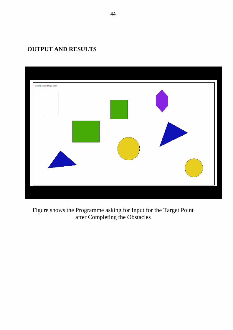
OUTPUT AND RESULTS
Figure shows the Programme asking for Input for the Target Point
after Completing the Obstacles
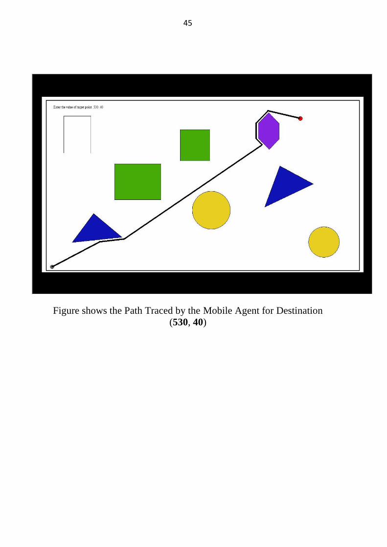
45
Figure shows the Path Traced by the Mobile Agent for Destination
(530, 40)
46
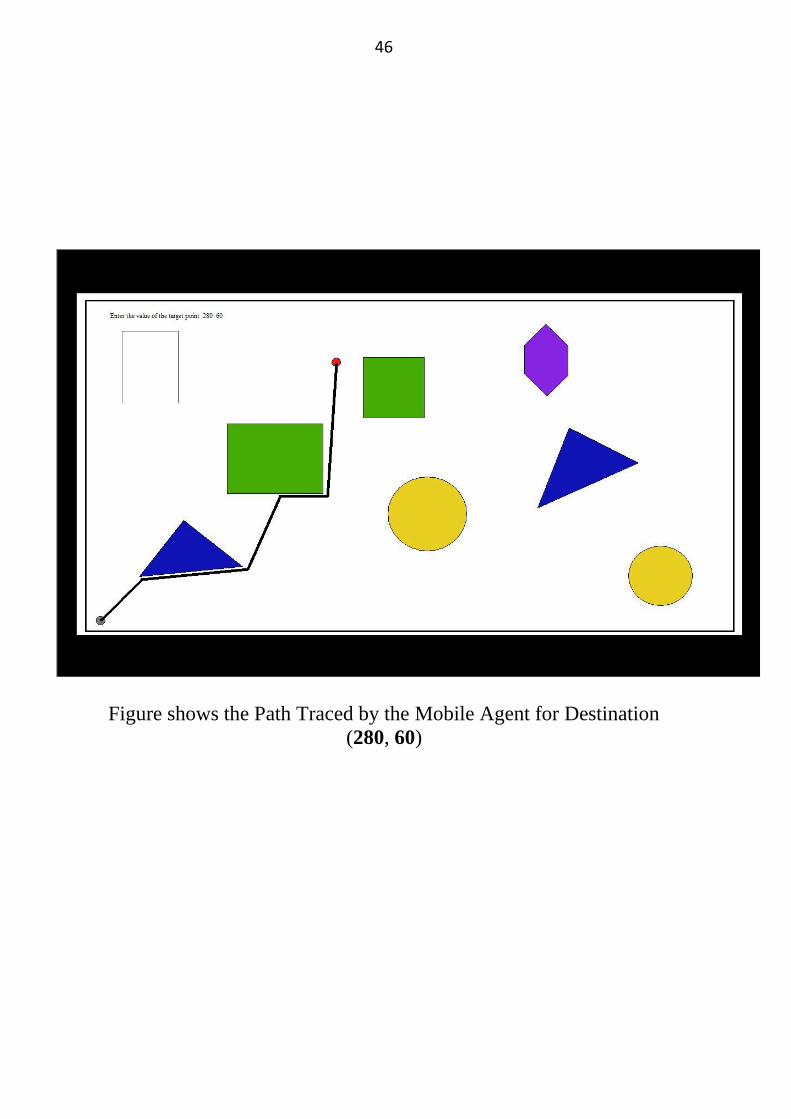
Figure shows the Path Traced by the Mobile Agent for Destination
(280, 60)
47
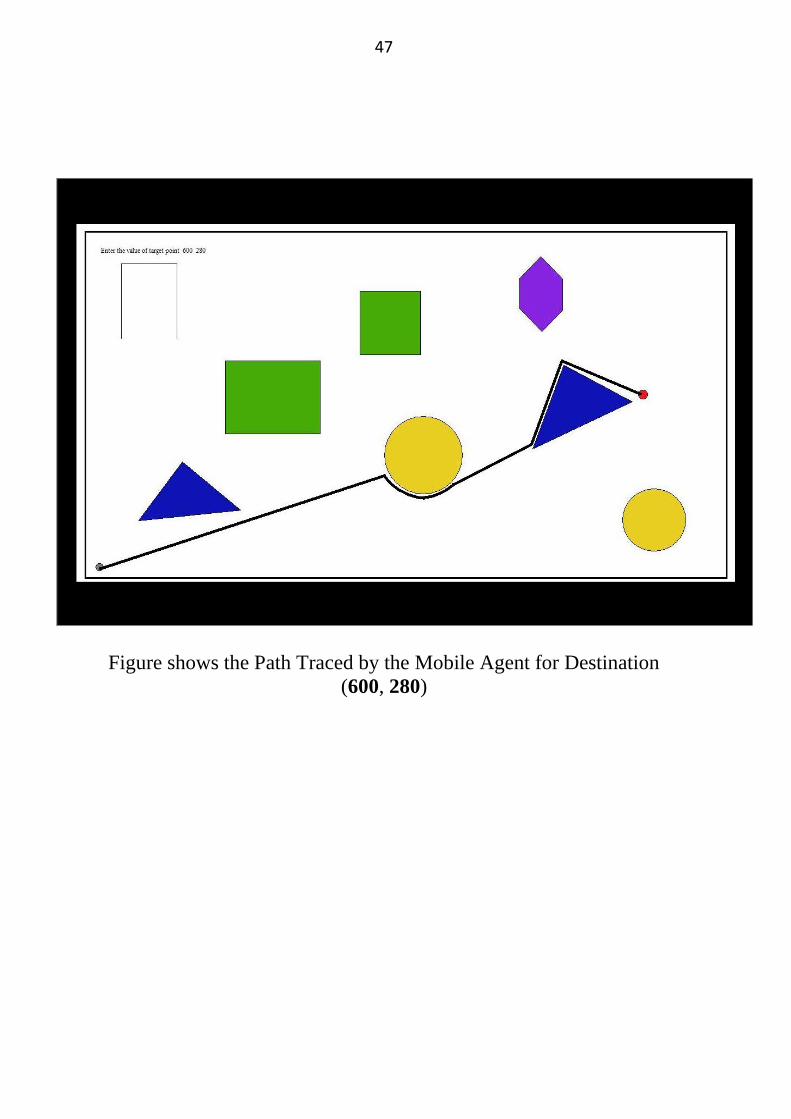
Figure shows the Path Traced by the Mobile Agent for Destination
(600, 280)
48
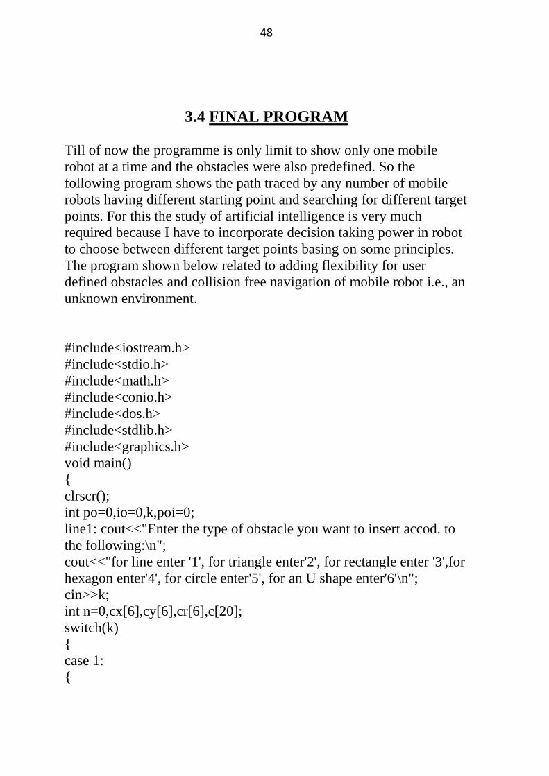
3.4 FINAL PROGRAM
Till of now the programme is only limit to show only one mobile
robot at a time and the obstacles were also predefined. So the
following program shows the path traced by any number of mobile
robots having different starting point and searching for different target
points. For this the study of artificial intelligence is very much
required because I have to incorporate decision taking power in robot
to choose between different target points basing on some principles.
The program shown below related to adding flexibility for user
defined obstacles and collision free navigation of mobile robot i.e., an
unknown environment.
#include<iostream.h>
#include<stdio.h>
#include<math.h>
#include<conio.h>
#include<dos.h>
#include<stdlib.h>
#include<graphics.h>
void main()
{
clrscr();
int po=0,io=0,k,poi=0;
line1: cout<<"Enter the type of obstacle you want to insert accod. to
the following:\n";
cout<<"for line enter '1', for triangle enter'2', for rectangle enter '3',for
hexagon enter'4', for circle enter'5', for an U shape enter'6'\n";
cin>>k;
int n=0,cx[6],cy[6],cr[6],c[20];
switch(k)
{
case 1:
{
49
poi++;
n=4;
c[poi]=0;
po++;
break;
}
case 2:
{
poi++;
n=6;
c[poi]=1;
po++;
break;
}
case 3:
{
poi++;
n=8;
c[poi]=1;
po++;
break;
}
case 4:
{
poi++;
n=12;
c[poi]=1;
po++;
break;
}
case 5:
{
io++;
n=0;
cout<<"enter the (x,y) coordinate of the circle center and its radius for
circle"<<io;
cin>>cx[io]>>cy[io]>>cr[io];
50
// c[poi]=0;
break;
}
case 6:
{
poi++;
n=8;
c[poi]=0;
po++;
break;
}
}
cout<<"Enter the co-ordinates of the figure interms of (x,y)";
int i,fi[10][20],ni[10];
for(i=0;i<n;i++)
{
cin>>fi[po][i];
if(c[poi]==1)
{
if(i==n-1)
{
fi[po][i+1]=fi[po][0];
fi[po][i+2]=fi[po][1];
ni[po]=(n/2)+1;
}
}
if(c[poi]==0)
{
ni[po]=n/2;
}
}
int ki;
cout<<"Do you want to add one more figure if yes enter 1 \n";
cin>>ki;
if(ki==1)
{
goto line1;
51
}
int no, mo, a[10],b[10],e[10],d[10], nt, x1[10], y1[10], x2, y2;
cout<<"Enter the no. of mobile agent";
cin>>no;
cout<<"Enter the starting points of "<<no<<"target points in the form
of (x,y)\n";
for(i=0;i<no;i++)
{
cin>>a[i]>>b[i];
}
cout<<"Enter the number of target points";
cin>>nt;
cout<<"Enter the target point co-ordinates in (x,y) form";
int j, di[10], ds=0, dk,ko,mp, si, ap, bp;
for(j=0;j<nt;j++)
{
cin>>x1[j]>>y1[j];
}
clrscr();
/* request auto detection */
int gdriver = DETECT, gmode, errorcode;
/* initialize graphics mode */
initgraph(&gdriver, &gmode, "c:\\tc\\bgi");
/* read result of initialization */
errorcode = graphresult();
if (errorcode != grOk) /* an error occurred */
{
printf("Graphics error: %s\n", grapherrormsg(errorcode));
printf("Press any key to halt:");
// line(5, 5, 30, 30);
// getch();
// exit(1); /* return with error code */
}
52
int pu;
for(pu=1;pu<=po;pu++)
{
switch(ni[pu])
{
case 4:
{
setcolor(1);
setfillstyle(2,1);
break;
}
case 5:
{
setcolor(2);
setfillstyle(1,2);
break;
}
case 7:
{
setcolor(3);
setfillstyle(1,3);
break;
}
}
drawpoly(ni[pu],fi[pu]);
}
int ic;
for(ic=1;ic<=io;ic++)
{
setcolor(4);
setfillstyle(1,4);
circle(cx[ic],cy[ic],cr[ic]);
}
getch();
for(j=0;j<nt;j++)
{
for(i=0;i<no;i++)
53
{
ds=ds+sqrt(pow((x1[j]-a[i]),2)+pow((y1[j]-b[i]),2));
}
di[j]=ds;
}
dk=di[0];
for(j=0;j<nt;j++)
{
if(dk>=di[j])
{
dk=di[j];
ko=j;
}
}
x2=x1[ko];
y2=y1[ko];
int x[12],y[12],ku[12]={ 1, 1, 1, 1, 1, 1, 1, 1, 1, 1, 1, 1}, ks1[12]={ 1,
1, 1, 1, 1, 1, 1, 1, 1, 1, 1, 1}, tj, tjn,mk[20],ksx[15];
line14: int k2c=0,klc=0,tpy,tny,p,ky1,kx1,ky2,kx2,yp,yn,lac,yrp,yrn;
for(j=0;j<no; j++)
{
x[j]=a[j];
y[j]=b[j];
if(x[j]!=x2 || y[j]!=y2)
{
if (ku[j]==4)
{
switch(ksx[j])
{
case 1:
{
goto line8;
}
case 2:
{
goto line9;
}
54
case 3:
{
goto line10;
}
case 4:
{
goto line11;
}
}
}
if(x2<a[j])
{
goto line8;
}
else
{
goto line9;
}
//if(x[j]>x2)
line8:x[j]--;
tj=0;
if(ks1[j]==1)
{
mk[j]=((y2-b[j])/(x2-a[j]))*10;
y[j]=(mk[j]*(x[j]-a[j])+b[j])/10;
}
for(si=1;si<=po;si++)
{
for(i=0;i<(2*ni[si]);i++)
{
if(i%2==0)
{
if(fi[si][i+3]>fi[si][i+1])
{
ky1=fi[si][i+3];
55
ky2=fi[si][i+1];
}
else
{
ky1=fi[si][i+1];
ky2=fi[si][i+3];
}
if(fi[si][i]>fi[si][i+2])
{
kx1=fi[si][i];
kx2=fi[si][i+2];
}
else
{
kx1=fi[si][i+2];
kx2=fi[si][i];
}
int mxy;
if(x[j]>(kx2-10) && x[j]<(kx1+10))
{
if(y[j]>(ky2-10) && y[j]<(ky1+10))
{
bp=fi[si][i+3]-fi[si][i+1];
ap=fi[si][i+2]-fi[si][i];
if(bp==0)
{
int ku[10];
y[j]=b[j];
outtextxy(x[j],y[j],"*");
delay(10);
//getch();
tj=1;
klc++;
ku[j]=4; ks1[j]=2;
goto line6;
}
if(ap==0)
56
{
if(b[j]<d[j])
{
p=-1;
}
if(b[j]>d[j])
{
p=1;
}
x[j]=a[j];
y[j]=b[j]+p;
outtextxy(x[j],y[j],"*");
delay(10);
//getch();
ku[j]=4;
klc++;
ks1[j]=2;
tj=1;
goto line6;
}
mxy= ((fi[si][i+3]-fi[si][i+1])/(fi[si][i+2]-fi[si][i]))*100;
p=(y[j]-(mxy*(x[j]-fi[si][i])/100)-
fi[si][i+1])/(sqrt(1+(pow((mxy/100),2))));
if(p<10)
{
lac=100*(sqrt(1+(pow((mxy/100),2))));
yrp=(lac/10)+(mxy/100)*(x[j]-fi[si][i])+fi[si][i+1];
yrn=((mxy/100)*(x[j]-fi[si][i]))+fi[si][i+1]-(lac/10);
yp=b[j]-yrp;
yn=b[j]-yrn;
if(yp<0)
{
yp=(-1)*yp;
}
if(yn<0)
{
57
yn=(-1)*yn;
}
if(yp>yn)
{
y[j]=yrn;
}
else
{
y[j]=yrp;
}
outtextxy( x[j], y[j], "*");
delay(10);
ku[j]=4;ks1[j]=2;
tj=1;
}
}
}
}
line6:
e[j]=a[j];
d[j]=b[j];
a[j]=x[j];
b[j]=y[j];
if(tj==0)
{
ku[j]=1;
ks1[j]=1;
}
else
{
ksx[j]=1;
}
}
}
if(tj==0)
{
outtextxy( x[j], y[j],"*");
58
delay(5);
}
goto line7;
//if(x[j]<x2)
//{
line9: x[j]++;
tjn=0;
if(ks1[j]==1)
{
mk[j]=((y2-b[j])/(x2-a[j]))*100;
y[j]=(mk[j]/100)*(x[j]-a[j])+b[j];
}
//tsi=tsi++;
for(si=1;si<=po;si++)
{
for(i=0;i<(2*ni[si]);i++)
{
if(i%2==0)
{
int ky1,kx1, ky2, kx2;
if(fi[si][i+3]>fi[si][i+1])
{
ky1=fi[si][i+3];
ky2=fi[si][i+1];
}
else
{
ky1=fi[si][i+1];
ky2=fi[si][i+3];
}
if(fi[si][i]>fi[si][i+2])
{
kx1=fi[si][i];
kx2=fi[si][i+2];
}
else
{
59
kx1=fi[si][i+2];
kx2=fi[si][i];
}
if(x[j]>=(kx2-10) && x[j]<=(kx1+10))
{
if(y[j]>=(ky2-10) && y[j]<=(ky1+10))
{
bp=fi[si][i+3]-fi[si][i+1];
ap=fi[si][i+2]-fi[si][i];
//mp=(bp/ap)*100;
if(bp==0)
{
int pqs;
pqs=(y[i]-fi[si][i+1]);
if(pqs<0)
{
pqs=pqs*(-1);
}
if(pqs<10)
{
int p;
y[j]=b[j];
outtextxy(x[i],y[j],"*");
delay(5);
klc++;
ku[j]=4; ks1[j]=2;
tjn=1;
goto line12;
}
}
if(ap==0)
{
int pqs;
pqs=x[i]-fi[si][i];
if(pqs<0)
{
60
pqs=pqs*(-1);
}
if(pqs<10)
{
if(b[j]<d[j])
{
p=-1;
}
if(b[j]>d[j])
{
p=1;
}
x[j]=a[j];
y[j]=b[j]+p;
outtextxy(x[j],y[j],"*");
delay(5);
//getch();
ku[j]=4; ks1[j]=2;
klc++;
tjn=1;
goto line12;
}
}
int mxy,pl;
mxy=((fi[si][i+3]-fi[si][i+1])/(fi[si][i+2]-fi[si][i]))*100;
pl=(y[j]-(mxy*(x[j]-fi[si][i])/100)-
fi[si][i+1])/(sqrt(1+(pow((mxy/100),2))));
if(pl<10)
{
//int mt;
//mt=((y[j]-ky1)/(x[j]-kx2-18))*100;
lac=100*(sqrt(1+(pow((mxy/100),2))));
yrp=(lac/10)+(mxy/100)*(x[j]-fi[si][i])+fi[si][i+1];
yrn=((mxy/100)*(x[j]-fi[si][i]))+fi[si][i+1]-(lac/10);
yp=b[j]-yrp;
yn=b[j]-yrn;
if(yp<0)
61
{
yp=(-1)*yp;
}
if(yn<0)
{
yn=(-1)*yn;
}
if(yp>yn)
{
y[j]=yrn;
}
else
{
y[j]=yrp;
}
outtextxy( x[j], y[j],"*");
delay(10);
//getch();
ku[j]=4; ks1[j]=2;
tjn=1;
}
}
}
}
line12:
e[j]=a[j];
d[j]=b[j];
a[j]=x[j];
b[j]=y[j];
if(tjn==0)
{
ku[j]=1;
ks1[j]=1;
}
else
{
ksx[j]=2;
62
}
}
}
if(tjn==0)
{
outtextxy( x[j], y[j],"*");
delay(10);
}
goto line7;
if(x[j]==x2)
{
if(y[j]>(y2+5) || y[j]<(y2-5))
{
if(y[j]>y2)
{
line10:
int tny=0;
y[j]--;
if(ks1[j]==1)
{
mk[j]=((y2-b[j])/(x2-a[j]))*100;
x[j]=a[j]+((y[j]-b[j])/(mk[j]/100));
}
for(si=1;si<=po;si++)
{
for(i=0;i<(2*ni[si]);i++)
{
if(i%2==0)
{
int ky1,kx1,ky2,kx2;
if(fi[si][i+3]>fi[si][i+1])
{
ky1=fi[si][i+3];
ky2=fi[si][i+1];
}
else
{
63
ky1=fi[si][i+1];
ky2=fi[si][i+3];
}
if(fi[si][i]>fi[si][i+2])
{
kx1=fi[si][i];
kx2=fi[si][i+2];
}
else
{
kx1=fi[si][i+2];
kx2=fi[si][i];
}
int mxy;
if(x[j]>(kx2-10) && x[j]<(kx1+10))
{
if(y[j]>(ky2-10) && y[j]<(ky1+10))
{
bp=fi[si][i+3]-fi[si][i+1];
ap=fi[si][i+2]-fi[si][i];
if(bp==0)
{
int ku[10];
y[j]=b[j];
if(a[j]<e[j])
{
p=-1;
}
if(a[j]>e[j])
{
p=1;
}
x[j]=a[j]+p;
outtextxy(x[j],y[j],"*");
tny=1;
klc++;
ku[j]=4; ks1[j]=2;
64
goto line13;
}
if(ap==0)
{
x[j]=a[j];
y[j]=b[j];
outtextxy(x[j],y[j],"*");
ku[j]=4;
klc++;
ks1[j]=2;
tny=1;
goto line13;
}
mxy= ((fi[si][i+3]-fi[si][i+1])/(fi[si][i+2]-fi[si][i]))*100;
int p;
p=(y[j]-(mxy*(x[j]-fi[si][i])/100)-
fi[si][i+1])/(sqrt(1+(pow((mxy/100),2))));
if(p<10)
{
lac=100*(sqrt(1+pow(mxy,2)));
yrp=(y[j]+((mxy/100)*fi[si][i])-fi[si][i+1]-(lac/10))/(mxy/100);
yrn=(y[j]+((mxy/100)*fi[si][i])-fi[si][i+1]+(lac/10))/(mxy/100);
yp=a[j]-yrp;
yn=a[j]-yrn;
if(yp<0)
{
yp=(-1)*yp;
}
if(yn<0)
{
yn=(-1)*yn;
}
if(yp>yn)
{
x[j]=yrn;
}
else
65
{
x[j]=yrp;
}
outtextxy( x[j], y[j],"*");
ku[j]=4;
ks1[j]=2;
tny=1;
}
}
}
}
line13:
e[j]=a[j];
d[j]=b[j];
a[j]=x[j];
b[j]=y[j];
if(tny==0)
{
ku[j]=1;
ks1[j]=1;
}
else
{
ksx[j]=3;
}
}
}
if(tny==0)
{
outtextxy( x[j], y[j],"*");
}
}
if(y[j]<y2)
{
line11:
int tpy=0;
y[j]++;
66
if(ks1[j]==1)
{
mk[j]=((y2-b[j])/(x2-a[j]))*100;
x[j]=a[j]+((y[j]-b[j])/(mk[j]/100));
}
for(si=1;si<=po;si++)
{
for(i=0;i<(2*ni[si]);i++)
{
if(i%2==0)
{
int ky1,kx1,ky2,kx2;
if(fi[si][i+3]>fi[si][i+1])
{
ky1=fi[si][i+3];
ky2=fi[si][i+1];
}
else
{
ky1=fi[si][i+1];
ky2=fi[si][i+3];
}
if(fi[si][i]>fi[si][i+2])
{
kx1=fi[si][i];
kx2=fi[si][i+2];
}
else
{
kx1=fi[si][i+2];
kx2=fi[si][i];
}
int mxy;
if(x[j]>(kx2-10) && x[j]<(kx1+10))
{
if(y[j]>(ky2-10) && y[j]<(ky1+10))
{
67
bp=fi[si][i+3]-fi[si][i+1];
ap=fi[si][i+2]-fi[si][i];
if(bp==0)
{
int ku[10];
y[j]=b[j];
if(a[j]<e[j])
{
p=-1;
}
if(a[j]>e[j])
{
p=1;
}
x[j]=a[j]+p;
outtextxy(x[j],y[j],"*");
tpy=1;
klc++;
ku[j]=4; ks1[j]=2;
goto line17;
}
if(ap==0)
{
x[j]=a[j];
y[j]=b[j];
outtextxy(x[j],y[j],"*");
ku[j]=4;
klc++;
ks1[j]=2;
tpy=1;
goto line17;
}
mxy= ((fi[si][i+3]-fi[si][i+1])/(fi[si][i+2]-fi[si][i]))*100;
int p;
p=(y[j]-(mxy*(x[j]-fi[si][i])/100)-
fi[si][i+1])/(sqrt(1+(pow((mxy/100),2))));
if(p<10)
68
{
lac=100*(sqrt(1+pow(mxy,2)));
yrp=(y[j]+((mxy/100)*fi[si][i])-fi[si][i+1]-(lac/10))/(mxy/100);
yrn=(y[j]+((mxy/100)*fi[si][i])-fi[si][i+1]+(lac/10))/(mxy/100);
yp=a[j]-yrp;
yn=a[j]-yrn;
if(yp<0)
{
yp=(-1)*yp;
}
if(yn<0)
{
yn=(-1)*yn;
}
if(yp>yn)
{
x[j]=yrn;
}
else
{
x[j]=yrp;
}
outtextxy( x[j], y[j],"*");
ku[j]=4;
ks1[j]=2;
tpy=1;
}
}
}
}
line17:
e[j]=a[j];
d[j]=b[j];
a[j]=x[j];
b[j]=y[j];
if(tpy==0)
{
69
ku[j]=1;
ks1[j]=1;
}
else
{
ksx[j]=4;
}
}
}
if(tpy==0)
{
outtextxy( x[j], y[j],"*");
}
}
line7:
if(x[j]!=x2 || y[j]!=y2)
{
k2c=1;
}
}
getch();
}
if(k2c==1)
{
goto line14;
}
else
{
goto line15;
}
}
}
line15:
getch();
}
70
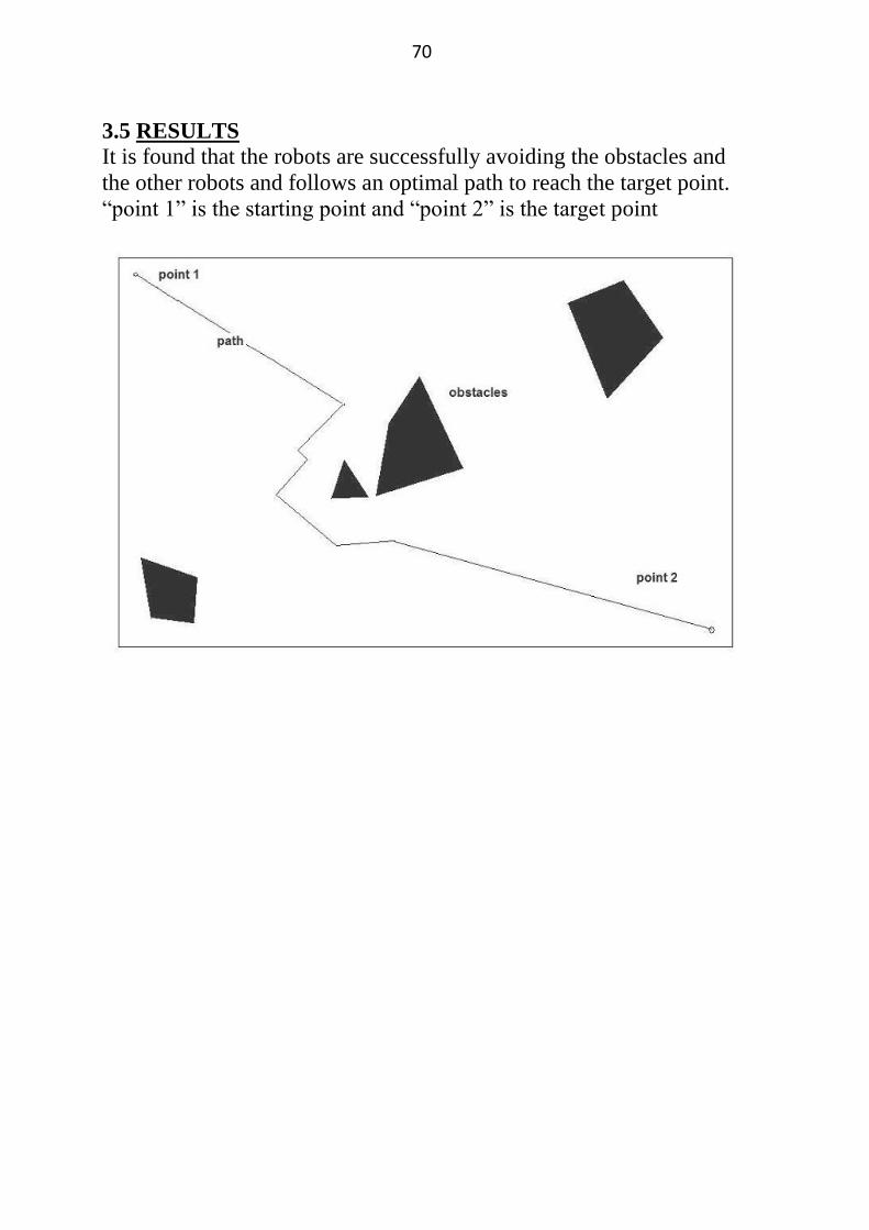
3.5 RESULTS
It is found that the robots are successfully avoiding the obstacles and
the other robots and follows an optimal path to reach the target point.
“point 1” is the starting point and “point 2” is the target point
71
Chapter 3
CONCLUSION
72
CONCLUSION:
The program written in C++ for the simulation of path
traced by mobile robots works successfully. The diagram shown in
the previous pages is the arena where the robot is placed. The robot
moves from start point and goes along the path shown in the figure
avoiding obstacles to red colour point which is the destination point.
When the robot was moving along its path it had some problems to
navigate when there exist obstacles more than one. The C++ compiler
was a very effective mode because of its fastness and good hardware
interfacing.
Applications:
1. This type of system can be used in automobiles for collision free
driving.
2. It can also be used handling waste material in nuclear reactions
where mobile robots have to perform the work accurately.
3. It can be used in transportation in industries.
73
REFERENCES
[1] Location estimation by omni-directional vision, Chih-JenWua,
Department of Computer Science, National Chiao Tung University,
Hsinchu 30010, Taiwan, Wen-Hsiang Tsai,Department of Computer
Science and Information Engineering, Asia University, Taichung,
41354, Taiwan. P.1-40
[2] The stable and precise motion control for multiple mobile robots,
Dayal Ramakrushna Parhi(a), Saroj Kumar Pradhan(b) , Anup Kumar
Panda(c), Rabindra Kumar Behera(d), (a)(d) Department of
Mechanical Engineering, N.I.T., Rourkela, Orissa,India (b)
Department of Mechanical Engineering, N.I.T., Hamirpur, H.P., India
(c)Department of Electrical Engineering, N.I.T., Rourkela, Orissa,
India.
[3] Temporal logic motion planning for dynamic robots, by Georgios
E. Fainekos a, Antoine Girard
b, Hadas Kress-Gazit
b, George J.
Pappasa .
a 3330 Walnut Street, GRASP Laboratory, University of
Pennsylvania, PA 19104, United States
b Laboratoire Jean Kuntzmann, Université Joseph Fourier, France
[4] Stigmergic cooperation of autonomous robots, Cezary Zielin ski*,
Piotr Trojanek. Institute of Control and Computation Engineering,
Warsaw University of Technology, ul. Nowowiejska 15/19, 00-665
Warsaw, Poland.
[5] A mixed analog-digital vision sensor for detecting objects
approaching on a collision course, Sigal Berman, Edna Schechtman ,
Yael Edan
[6] A case-based approach for coordinated action selection in robot
soccer, by Raquel Ros, Josep Lluís Arcos, Ramon Lopez de Mantaras
, Manuela Veloso.
74
[7] Study on some navigation schemes of a real robot tackling moving
obstacles(Nirmal Baran Hui, Dilip Kumar Pratihar)
[8] Pratihar DK. Algorithmic and soft computing approaches to robot
motionplanning. Machine Intelligence and Robotic Control
2003;5(1):1–16.
[9] Latombe J-C. Robot motion planning. Dordrecht: Kluwer
Academic Publisher; 1991.
[10] Liu YH, Arimoto S. Path planning using a tangent graph for
mobile robots among polynomial and curved obstacles. The
International Journal of Robotics Research 1992;11(4):376–82.
[11] Kant K, Zucker SW. Towards efficient planning: the path
velocity decomposition. The International Journal of Robotics
Research 1986;5(1):72–89.
[12] Fujimura K, Samet H. Accessibility: a new approach to path
planning amongmoving obstacles. In: Proceedings of IEEE
conference on computer vision andpattern recognition, Ann Arbor,
MI, 1988. p. 803–7.
[13] Lamadrid JG, Gini ML. Path tracking through uncharted moving
obstacles.IEEE Transactions on Systems, Man and Cybernetics
1990;20(6):1408–22.
[14] Slack MG, Miller DP. Path planning through time and space in
dynamic domains. In: Proceedings of the international joint
conference on artificial intelligence; 1987. p. 1067–70.
[15] Fiorini P, Shiller Z. Motion planning in dynamic environments
using the relative velocity paradigm. In: Proceedings of IEEE
conference on robotics and automation; 1993. p. 560–5.
[16] Brooks RA. A robust layered control system for a mobile robot.
IEEE Transactions on Robotics and Automation 1986;RA-2:14–23.
75
[17] Simmons R. The curvature-velocity method for local obstacle
avoidance. In: Proceedings of the international conference on robotics
and automation, vol.4; 1996. p. 2275–82.
[18] Fox D, Burgard W, Thrun S. The dynamic window approach to
collision avoidance. IEEE Robotics & Automation Magazine
1997;23:23–33.
[19] LaValle SM, Kuffner JJ. Randomized kinodynamic planning.
International Journal of Robotics Research 2001;20(5):378–400.
[20] Koren Y, Borenstein J. Potential field methods and their inherent
limitations for mobile robot navigation. In: Proceedings of the IEEE
conference on robotics and automation, Sacramento, CA, 1991. p.
1398–404.
[21] Using genetic algorithms for robot motion planning, Juan
Manuel Ahuactzin, El-Ghazali Talbi, Pierre Bessiere, and Emmanuel
Mazer .1-10.
[22] Spatial Learning and Localization in Animals: A Computational
Model and its Implications for Mobile Robots, by Karthik
Balakrishnan, Olivier Bousquet, and Vasant Honovar .p.1-50.
[23] Dynamic trajectory planning for cross-country navigator, by
Barry L. Brumitt, R. Craig Coulter, Anthony Stentz.
[24] An Opportunistic Global Path Planner, by John F. Canny and
Ming Chieh Lin.
[25] On All-Terrain Vehicle Motion Planning , by Moez Cherif.
[26] Robust Path Planning in the Plane, by Fernando De la Rosa,
Christian Laugier, and Jose Najera. [27] The Geometrical Representation of Path Planning Problems, by
Leo Dorst, Indur Mandhyan, and Karen Trovato.
76
[28] Collision-Free Object Movement Using Vector Fields, by Parris
K. Egbert and Scott H. Winkler.
[29] Finding an Unpredictable Target in a Workspace with Obstacles,
by Steven LaValle, David Lin, Leonidas Guibas, Jean-Claude
Latombe, and Rajeev Motwani.
[30] A Mobile Robot Navigation Exploration Algorithm, by
Alexander Zelinsky.
[31] An optimal pathfinder for vehicles in real-world digital terrain
maps, by Frank Markus Jönsson
Related Documents