SANEAMENTO / FEVEREIRO DE 2012 80 SANITARY ENGINEERING LESSON 10 / SUMMARY LESSON 10 WASTEWATER DRAINAGE SYSTEMS Wastewater drainage systems evolution; Current situation in Portugal; Components of the systems; Examples of existing wastewater systems (components and layout); Types of systems. Advantages and inconvenientes; Plant layout.

Welcome message from author
This document is posted to help you gain knowledge. Please leave a comment to let me know what you think about it! Share it to your friends and learn new things together.
Transcript

SANEAMENTO / FEVEREIRO DE 2012 80
SANITARY ENGINEERINGLESSON 10 / SUMMARY
LESSON 10
WASTEWATER DRAINAGE SYSTEMS
� Wastewater drainage systems evolution;
� Current situation in Portugal;
� Components of the systems;
�Examples of existing wastewater systems (components and layout);
�Types of systems. Advantages and inconvenientes;
�Plant layout.

SANEAMENTO / FEVEREIRO DE 2012 81
WASTEWATER DRAINAGE SYSTEMS
A BIT OF HISTORY
3000 AC: Mohengo-Doro (Hindu civilization, nowadays Pakistan);
1000 a 3000 AC – Cnosso, Crete;
500 AC: Roman Cloaca Maxima (cloacarium e curatores clocarium);
1650 DC: 1st buried collecting pipe (London);
1800 DC: Collecting pipes/tunnels of Paris;
1870 DC: 1st separative systems (Lenox e Memphis, USA).
Public latrine ruins in Ephessos, Turkey (1st century)
Boat trip to Paris sewages, 1896

SANEAMENTO / FEVEREIRO DE 2012 82
WASTEWATER DRAINAGE SYSTEMS
HISTORICAL ASPECTS IN PORTUGAL
D. João II (1400 DC): Pipes cleaning;
1755: Methodical pipeline-collecting mesh;
Lisbon: “cascões” collecting pipes;
1950 – Setúbal: “canecos” in front of houses to collect “excreta”.
Saimel (Pombalino) Cascões

SANEAMENTO / FEVEREIRO DE 2012 83
WASTEWATER DRAINAGE SYSTEMS
HISTORICAL ASPECTS IN PORTUGAL
Higyenist line of thought
� Concerns about effluent treatment and public health;
� Analogy between city network infrastructures (water supply andwastewater drainage) and body circulatory system (arteries and veins).Ecology and urban metabolism.
Urban water cycle
� Urban metabolism (entry of water, chemicals, materials and energy, andoutput of liquid, solid and gaseous wastes). Open system and closedsystem (effluent reuse, eco-efficiency)
Ceramic material Cast iron

SANEAMENTO / FEVEREIRO DE 2012 84
WASTEWATER DRAINAGE SYSTEMS
HISTORICAL ASPECTS IN PORTUGAL
Séc. XX – Construction of separative Systems
1930: Porto;
40s: part of Barreiro;
50s: Beja, Caparica, Setúbal, …; Costa de Caparica: first network in the countrywith fiber cement pipes and watertight seals;
60s: Viseu, Tomar, …;
60s, 70s: Lisboa, Elvas, …;
80s: Alcanena (collection of effluents from tanneries, Alviela decontamination);
90s e 2000s: Estoril Coast system, large systems in the Lisbon region:Alcântara, Chelas e Beirolas, Frielas, S. João da Talha, Quinta da Bomba, Portinho daCosta, Mutela, Vale do Ave, SIMRIA, ….

SANEAMENTO / FEVEREIRO DE 2012 85
WASTEWATER DRAINAGE SYSTEMS
HISTORICAL EVOLUTION OF SYSTEMS
Former pluvial network (until XIX century)
Former pluvial network (until XIX century)
Wastewater treatment inserted in a unitary system (XX century)
Drainage basin
Sewage network
Emissaries
Receiving environment
Buildings
Treatment
CSOs
Industries
Rainwater
Domestic and Industrial WW
Mix
Exutor

SANEAMENTO / FEVEREIRO DE 2012 86
WASTEWATER DRAINAGE SYSTEMS
HISTORICAL EVOLUTION OF SYSTEMS
Drainage basin
Sewage network
Emissaries
Receiving environment
Buildings
Treatment
CSOs
Industries
Rainwater
Domestic and Industrial WW
Mix
Rainwater separative system with eventual treatment
Separative system of domestic wastewater, with mandatory treatment and exutor conveniently inserted
Exutor
Separative wastewater system with pre-treated industrial wastewater connection

SANEAMENTO / FEVEREIRO DE 2012 90
WASTEWATER DRAINAGE SYSTEMS
COMPONENTS OF WASTEWATER DRAINAGE SYSTEMS
1. Buildings interior networks
a1) Stormwater
a2) Domestic, industrial and commercial wastewater
2. Branches to connect to the main public network
3. Main network components: pipes, manholes, storm drains (in combined or separative
networks);

SANEAMENTO / FEVEREIRO DE 2012 91
WASTEWATER DRAINAGE SYSTEMS
COMPONENTS OF WASTEWATER DRAINAGE SYSTEMS
4. Pumping stations and other elevation devices
5. Collection and transport pipes
6. Sand and/or fact retention chambers, upstream the drainage network:

SANEAMENTO / FEVEREIRO DE 2012 92
WASTEWATER DRAINAGE SYSTEMS
7. Weirs for control of overflows;
8. Inverted shyphons
9. Special works: crossings, bridge-channel, damping and retention reservoirs;
.
COMPONENTS OF WASTEWATER DRAINAGE SYSTEMS

SANEAMENTO / FEVEREIRO DE 2012 93
WASTEWATER DRAINAGE SYSTEMS
10. Tunnels
11. WWTP
12. Marine outfalls
COMPONENTS OF WASTEWATER DRAINAGE SYSTEMS

SANEAMENTO / FEVEREIRO DE 2012 94
WASTEWATER DRAINAGE SYSTEMSEXAMPLES OF SYSTEMS
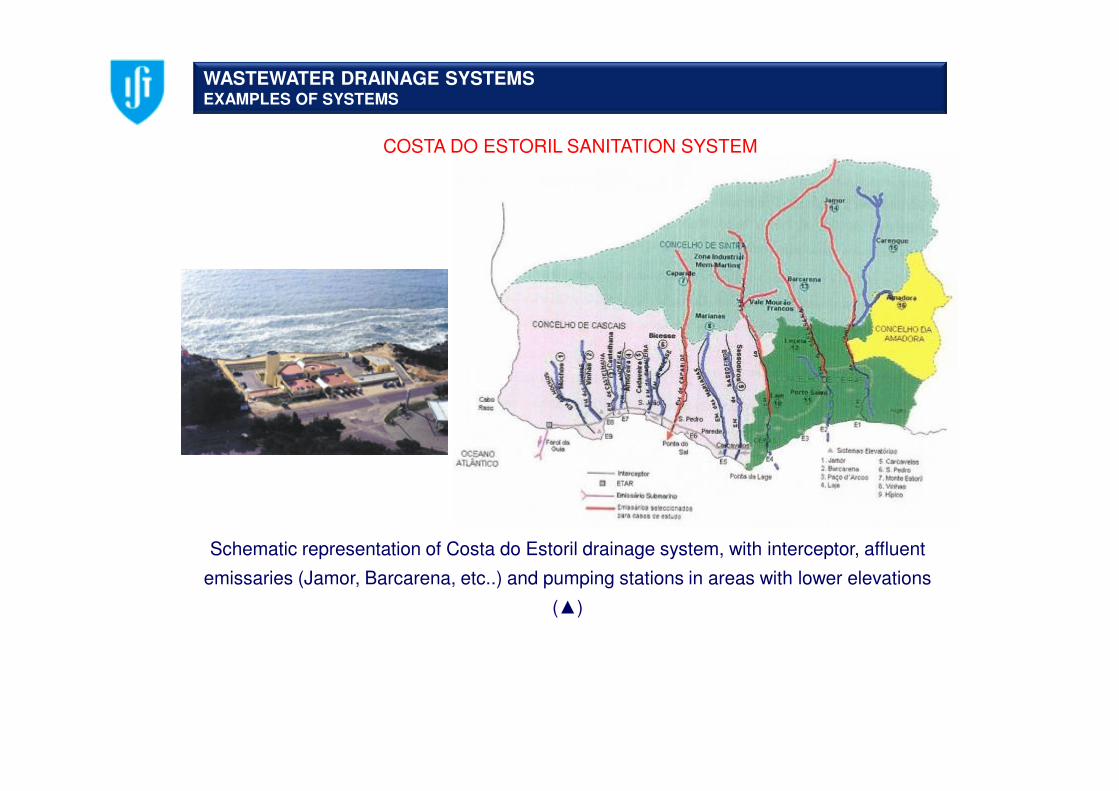
COSTA DO ESTORIL SANITATION SYSTEM
�Population: 900 000 inhab.
�Main interceptor: ø 1,5 m a ø 2,5 m, em 25 km.
�Several pumping stations (in lower elevation areas) and emissaries affluent to the
general intercetor
�WWTP (two phases)
Liquid phase (underground), near Guia (Cascais) in improvement;
Solid phase (sludge treatment) on the surface, in Outeiro da Lota, 4 km away.
�Marine outfall with two diffusers 400 m, for release into the sea (with 2700 m long, 40 m
deep).
�WWTP (physico-chemical treatment, following filtration and disinfection by UV, during
bathing season)

SANEAMENTO / FEVEREIRO DE 2012 95
WASTEWATER DRAINAGE SYSTEMSEXAMPLES OF SYSTEMS
Service area of the wastewater drainage system of Costa do Estoril (Counties of Oeiras,
Cascais and part of Amadora and Sintra)
COSTA DO ESTORIL SANITATION SYSTEM
SIMBOLOGY
Interceptor system
Eduction pipe
Pumping station
Main
SANEAMENTO / FEVEREIRO DE 2012 96
WASTEWATER DRAINAGE SYSTEMSEXAMPLES OF SYSTEMS
Schematic representation of Costa do Estoril drainage system, with interceptor, affluent
emissaries (Jamor, Barcarena, etc..) and pumping stations in areas with lower elevations
(▲)
COSTA DO ESTORIL SANITATION SYSTEM

SANEAMENTO / FEVEREIRO DE 2012 97
WASTEWATER DRAINAGE SYSTEMSEXAMPLES OF SYSTEMS
S. JOÃO DA TALHA SANITATION SYSTEM
Location: Loures County (Freguesias de Bobadela, Sta Iria da Azóia e S. João da Talha);
North Interceptor: L= 3,8 km;
DN 315 a 800 mm (connecting section to WWTP : L = 8 m;
DN = 1000 mm);
South Interceptor: L= 2 km;
DN 400 a 600 mm;
WWTP Physico-chemical and biological treatment (activated sludge);
Operating since 1997;
Project population= 130 000 equivalent habitants;
Qhousehold (average)= 5 980 m3/day;
Qtotal (average)(industrial+household) = 12 582 m3/day.
(65% of the pollution load from industrial sources)

SANEAMENTO / FEVEREIRO DE 2012 98
WASTEWATER DRAINAGE SYSTEMSEXAMPLES OF SYSTEMS
SCHEMATIC REPRESENTATION OF S. JOÃO DA TALHA SANITATION SYSTEM

SANEAMENTO / FEVEREIRO DE 2012 99
WASTEWATER DRAINAGE SYSTEMS
COMPONENTS OF WASTEWATER DRAINAGE SYSTEMS

SANEAMENTO / FEVEREIRO DE 2012 100
WASTEWATER DRAINAGE SYSTEMS
TYPES OF SYSTEMS
Decree nº23/95 – Article 116º
�Combined systemsConsisting of a single network where stormwater and household,commercial and industrial wastewater are all accepted; they collect anddrain all types of wastewater produced.
�Separative systemsComposed of two distinct networks, one for the drainage of household,commercial and industrial wastewater, and another to the drainage ofstormwater and alike.
�Mixed systemsConsisting of the combination of the two previous types in witch part of thecollectors network operates as a unitary system and the rest as a separativesystem.
�Partialy separative systemsWhere it is accepted, in exceptional conditions, the connection of rainwater from interior courtyards to the collector of household wastewater.

SANEAMENTO / FEVEREIRO DE 2012 101
WASTEWATER DRAINAGE SYSTEMSTYPES OF SYSTEMS: ADVANTAGES AND DISADVANTAGES
COMBINED VERSUS SEPARATIVE SYSTEMS
� Advantages of combined systems
� Cheaper
� Easier to build
� Allows the treatment of part of stormwater flows
� Disadvantages
� The over flow that occurs when it rains and the WWTP capacity is exceeded, is amix of stormwater and community wastewater (combined sewage overflow). So,when discharged into the receiving environment, can lead to pollution andcontamination problems;
� Adequate hydraulic conditions are hard to maintain during dry weather periods(sedimentation of suspended solids, risk of formation of hydrogen sulfide, odorsand corrosion of the material collectors)
� When the first rainfall event occurs, after a prolonged drought, the WWTPreceives high pollutant loads (First flush effect)

SANEAMENTO / FEVEREIRO DE 2012 102
WASTEWATER DRAINAGE SYSTEMSTYPES OF SYSTEMS: ADVANTAGES AND DISADVANTAGES
COMBINED VERSUS SEPARATIVE SYSTEMS
� Disadvantages (cont.)
� Some components need to have a syphon to prevent odour disturbances (guttersand other components at the network inlet);
� In unitary systems, mains, even short ones, can have large diameters. Inseparative systems a shorter pipe can be installed, as long as the discharge ismade in a nearby water line;
� In separate stormwater systems the pipes do not need to be protected againstcorrosion, since they only carry runoff water, with practically no corrosive effects;
� In unitary systems the WWTP capacity is 2 to 3 times higher than in separatesystems

SANEAMENTO / FEVEREIRO DE 2012 103
WASTEWATER DRAINAGE SYSTEMS
REGULATION FOR NEW SYSTEMS
Decree nº23/95 – Article 119º
1. When designing a public wastewater drainage system in new urbanization areas, a
separative system should be adopted;
2. The household and industrial drainage systems must be designed together, as well
as the stormwater system (independently of being built in different stages).
Decree nº 23/95 – Article 120°: Remodeling existing systems
3. When remodelling existing systems, a transition to a separate systems should be
considered.

SANEAMENTO / FEVEREIRO DE 2012 104
WASTEWATER DRAINAGE SYSTEMS
SYSTEM DESIGN CONSIDERATIONS
Decree nº 23/95 – Article 118º
1. For the design of the wastewater drainage system, the final effluent disposal should be
considered, both in terms of natural resources protection, public health and economic
aspects;
2. The drainage network should cover the entire service area, as much as possible by
gravity flow.

SANEAMENTO / FEVEREIRO DE 2012 105
WASTEWATER DRAINAGE SYSTEMS
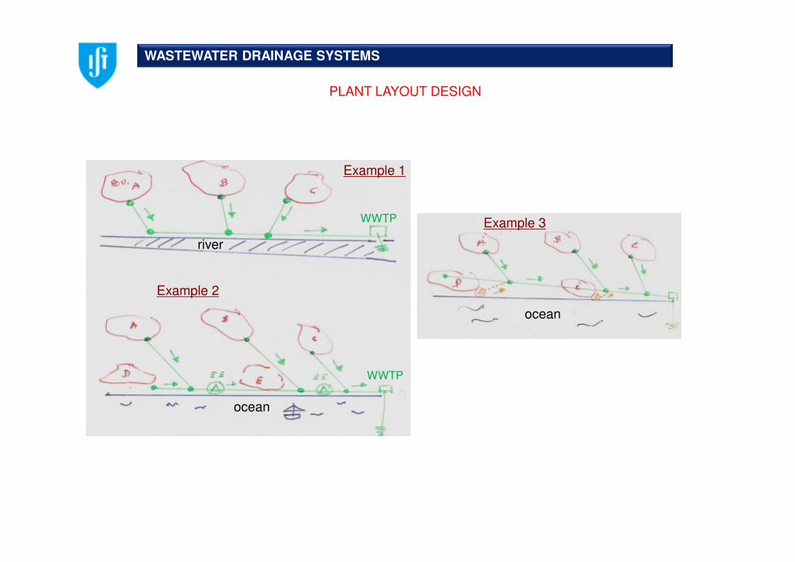
PLANT LAYOUT DESIGN
�In urban areas the pipes and manholes should be under the street.
�Outside urban areas the collection and transport pipes should develop allong valey
lines or allong the shore.
�The design depends on the final destination of the effluents.
GENERAL PRINCIPLES
a) Distance to urban centers
A1) Layout along valleys (rivers);
A2) Layout along the coast, such as pumping stations (near the ocean or sea);
b) Discharge away from bathing áreas;
c) Discharge should be made in areas with good dilution and dispersion conditions.
SANEAMENTO / FEVEREIRO DE 2012 106
WASTEWATER DRAINAGE SYSTEMS
PLANT LAYOUT DESIGN
river
ocean
WWTP
WWTP
Example 2
Example 3
Example 1
ocean

SANEAMENTO / FEVEREIRO DE 2012 107
WASTEWATER DRAINAGE SYSTEMS
LESSON 11
� System design steps
� Design flows and hydraulic criteria
� Sewer profile
� Sewer installation. Manholes

SANEAMENTO / FEVEREIRO DE 2012 108
WASTEWATER DRAINAGE SYSTEMS
DESIGN MAIN STEPS
� Collection of necessary data;
� Collection of information about possible restrictions and covered area;
� Choose the most suitable drainage system, how it will process the wastewatertreatment and final disposure, as well as all the system componentes;
� Analysis of economically viable alternative solutions;
� Hydraulic/sanitary design of all collectors (diameter and inclination), and all othersystem components, for the design flow;
� Delivery of reports and drawings

SANEAMENTO / FEVEREIRO DE 2012 109
WASTEWATER DRAINAGE SYSTEMS
DESIGN MAIN STEPS
1. Use adequate cartography: topographic mapping scale 1/1000 or 1/2000 of the current
urbanized area and the future expansion area, where all the proper information
appears(water lines, etc..).
2. Plant layout should take into account topography of the zone (gravity flow) and soil
nature, overlapping with other networks and relevant infrastructures
3. After the first plant layout, visit the area in order to collect more detailed information,
including:
a) best location of branch lines (front versus rear);
b) nature of the terrain (sand, clay or hard/soft rock);
c) type of flooring (asphalt, pavement, macadam …);
d) Watercourses crossing (bridges, viaducts, ... etc..).

SANEAMENTO / FEVEREIRO DE 2012 110
WASTEWATER DRAINAGE SYSTEMS
DESIGN MAIN STEPS
e) Outfalls layout
f) Groundwater levels (problems in executing the works and calculation of the
infiltration flow);
g) If pumping stations are planned, examine whether there is enough power and
study the resource manifold location;
h) Even if the project does not include the study of the treatment plant, analyze its
possible location;
4. Location of manholes.

SANEAMENTO / FEVEREIRO DE 2012 111
WASTEWATER DRAINAGE SYSTEMS
PLANT LAYOUT CONSTRAINS
Decree nº23/95 – Article 136º
1. Pipes should be placed on the axis of the paved area
2. In large streets with large sidewalks the pipes can be
placed outside the paved area, while respecting the
minimum distance of 1m in relation to property
boundaries
3. Pipes can be installed in both sides of the street more economic.
4. The placement relative to water supply systems must be ensured.

SANEAMENTO / FEVEREIRO DE 2012 112
WASTEWATER DRAINAGE SYSTEMS
PLANT LAYOUT CONSTRAINS
Decree nº23/95 – Article 136º
5. In order to minimize the risk of undue connections in the
network, the sewage pipe should be installed to the right of
the stormwater pipe, considering the flow direction;
6. No infrastructures can be built over drainage pipes;
7. If the previous rule is impossible to ensure, infrastructures
built over drainage pipes should be done ensuring a good
functioning of the pipes as well as a full access and water
tightness

SANEAMENTO / FEVEREIRO DE 2012 113
WASTEWATER DRAINAGE SYSTEMSPROJECT ASPECTS
1. It is mandatory to implement manholes:
a) in pipe junctions;
b) where pipes change direction, slope and
diameter;
c) in straight line pipes manhole distance should
not exceed 60 and 100 m for pipes that cannot
and can be visited, respectively.
MANHOLE LOCATION CRITERIA
Decree nº23/95 – Article 155º
2. Maximum distances referred previously can increase depending on the cleaning
methods available for the firs case and exceptionally for the second

SANEAMENTO / FEVEREIRO DE 2012 114
SEWER SYSTEM
PHASES OF THE STUDY: SYNTHESIS
1.Plant layout of the drainage system
2.Determine design flows
3.Draw longitudinal profile and determine hydraulicconditions

SANEAMENTO / FEVEREIRO DE 2012 115
SEWER SYSTEM
DESIGN FLOWS
Decree nº 23/95 – Artigo 132º: Design flows
1. On sewer systems, for domestic or indutrial wastewater, the design flows that
considered correspond to the ones predicted for the design life, this is, it should be
considered the average annual flow affected by a peak factor, to which the infiltration flow
is added
3. For the year of commencement of operation of the system, the hydraulic-sanitary
conditions of the system’s flow should be verified (height and velocity).
Decree nº 23/95 – Artigo 123°: Inflow coeficient
1. The inflow coeficient is the value by which the per capita water demand should be
multiplied as to have the wastewater production per capita
2. The network Inflow coefficient should be discriminated according to identic
characteristic areas, that depend on the extension of green and gardened areas or
agricultural land and habits of the population, values vary usually between 0.7 and 0.9.

SANEAMENTO / FEVEREIRO DE 2012 116
DESIGN FLOWS
1.Determine the population that is connected to each stretch
2.Determine the accumulated population associated with each stretch
3.Determine design flow
Qtotal = Q domestic+ Q industrial + Q inflow
where:
Qtotal - total flow to be transported
Q domestic - flow due to population activities
Q industrial - flow from industries
Q infiltration - infiltration form groundwater and storm water
SEWER SYSTEMDESIGN FLOWS

SANEAMENTO / FEVEREIRO DE 2012 117
DESIGN FLOWS
4.Determine infiltration flow
Common use: 0 < Qi < Qm
According to the Article 126º do DR 23/95: for D ≤ 300 mm then Qi = Qm
5.Determine peak flow
Q domestic= Fh x ( ∑ Kr x Population x Per capita water demand)
Fh - instant peak factor (varies with the population as
seen in Artigo 125º do DR 23/95) |
Kr - infiltration coefficient usually varies between0,70 a 1,0, as not all the water that is used is drained to the sewers (losses, irrigation, washing, etc.)
Pop
601,5Fh +=
SEWER SYSTEMDESIGN FLOWS

SANEAMENTO / FEVEREIRO DE 2012 118
SISTEMAS DE DRENAGEM DE ÁGUAS RESIDUAIS
HYDRAULIC DESIGN CRITERIA
� Minimum diameter (Artigo 126º do DR 23/95) |
D min = 200 mm
� Maximum flow height (Artigo 133º do DR 23/95): |
a) domestic wastewater flows
D ≤ 500 mm y máx / D = 0,50
D > 500 mm y máx / D = 0,75
b) combined wastewater or storm water flows
y máx / D = 1
� Maximum velocity (Artigo 133º do DR 23/95): |
V máx = 3 ms-1 domestic wastewater flows
V máx = 5 ms-1 combined wastewater or storm water flows
SEWER SYSTEMHYDRAULIC DESIGN CRITERIA

SANEAMENTO / FEVEREIRO DE 2012 119
SISTEMAS DE DRENAGEM DE ÁGUAS RESIDUAIS
HYDRAULIC DESIGN CRITERIA
� Minimum and maximum slope, for constructive reasons [Artigo 133º do DR 23/95] |
J mín = 0,3%
J máx = 15%
Slopes inferior to the prescribed minimum may be admitted, as long as the leveling and
the transport power are guaranteed and, in case slopes higher than the maximum are
necessary, special anchoring devices should be provided
� J mín = 1/ D (mm) European guidelines
SEWER SYSTEMHYDRAULIC DESIGN CRITERIA
SANEAMENTO / FEVEREIRO DE 2012 120
SISTEMAS DE DRENAGEM DE ÁGUAS RESIDUAIS
HYDRAULIC DESIGN CRITERIA
Self-cleaning
Self-cleaning conditions must be ensured for year 0 and maintained in order that the solids
settled during low flow hours are dragged during peak hours.
� self-cleaning criteria (velocity in year 0) [Artigo 133º do DR 23/95]:
V Auto-limpeza = 0,6 ms-1 domestic wastewater flows
V Alimpeza = 0,9 ms-1 combined wastewater or storm water flows
When these limits are not achieved, as it happens on the top of the network, the slopes
should ensure that the minimum is met for a full section flow.
SEWER SYSTEMHYDRAULIC DESIGN CRITERIA
MP1

Slide 120
MP1 colectores de cabeceiraMafalda Pinto; 11-06-2014

SANEAMENTO / FEVEREIRO DE 2012 121
1º Each stretch between manholes should be dimensioned starting upstream todownstream. No downstream stretch can be dimensioned before the previousupstream stretches have been determined;
2º Diameter and slope should be selected according to the longitudinal profile, in orderto minimize land movement;
3º Slopes must respect maximum and minimum values due to constructive reasons
4º Hydraulic conditions, flow height and velocity, must be checked for peak flow on thedesign year regarding transport capacity (h/D and Vmax)
5º Velocity and transport capacity should be equal or superior to the minimum required(self-cleaning), for the peak flow on the year of commencement of operation
HYDRAULIC DESIGN STEPS
SEWER SYSTEMHYDRAULIC DESIGN CRITERIA
SANEAMENTO / FEVEREIRO DE 2012 122
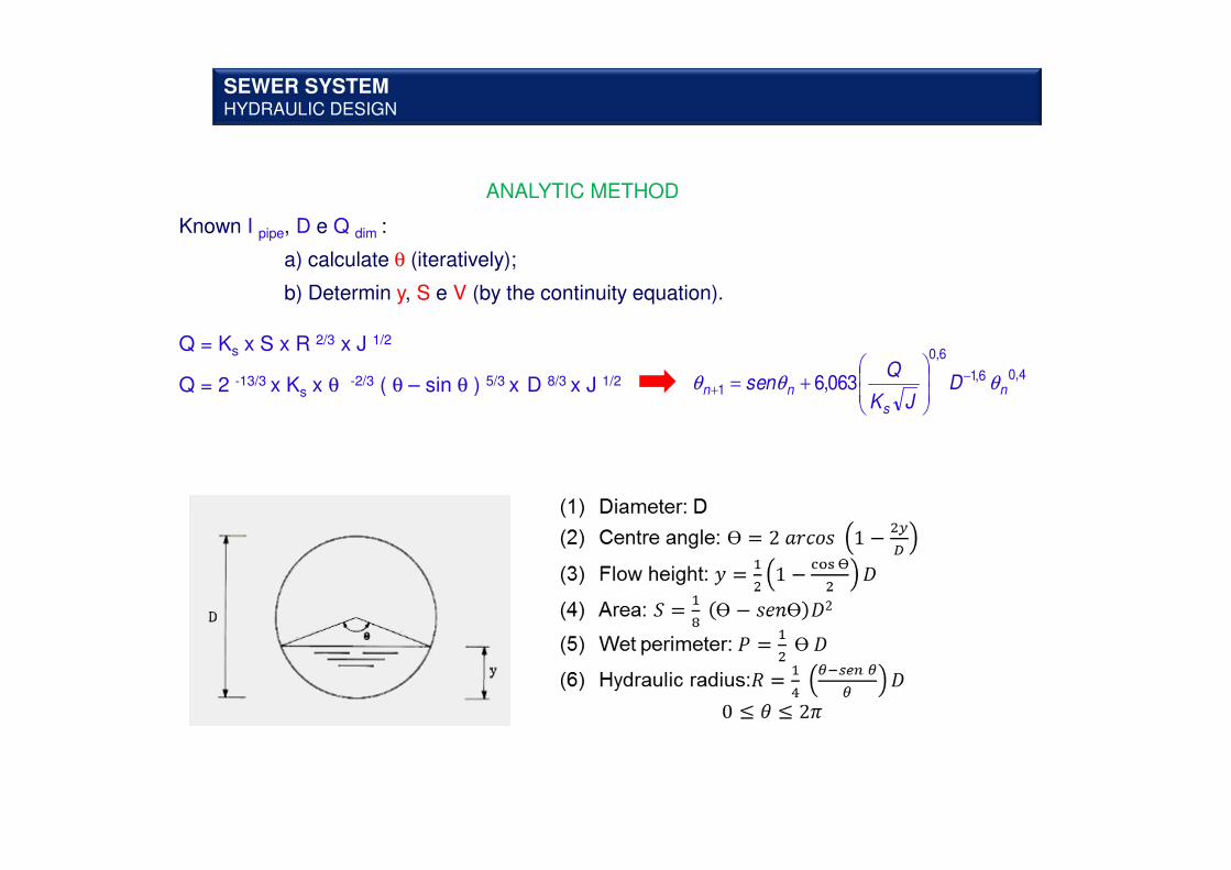
ANALYTIC METHOD
Known I pipe, D e Q dim :
a) calculate θ (iteratively);
b) Determin y, S e V (by the continuity equation).
Q = Ks x S x R 2/3 x J 1/2
Q = 2 -13/3 x Ks x θ -2/3 ( θ – sin θ ) 5/3 x D 8/3 x J 1/2 4,06,1
6,0
1 063,6 n
s
nn DJK
Qsen θθθ −
+
+=
SEWER SYSTEMHYDRAULIC DESIGN

SANEAMENTO / FEVEREIRO DE 2012 123
Known I pipe, D e Q dim :
a) Calculate Q f e V f
b) determine the relation Q dim / Q f
c) use the abacus of the hydraulic properties of
the circular sections :
Q-curve
Q dim / Q f y / D y
V-curve
y / D V / V f V
GRAPHICAL METHOD
SEWER SYSTEMHYDRAULIC DESIGN

SANEAMENTO / FEVEREIRO DE 2012 124
Strecht Population [hab] Q m f p Q inf Q dim D I y/D V real τreal Q sc V sc
[-] Affluent Accumulated [L/s] [-] [L/s] [L/s] [mm] [m/m] [-] [m/s] [N/m2] [L/s] [m/s]
1-2
2-3
...
HYDRAULIC CONDITIONS
�1 Table for design for Qpeak for Year 40
�1 Table for verifying for Qpeak for Year 0
SEWER SYSTEMHYDRAULIC DESIGN
SANEAMENTO / FEVEREIRO DE 2012 125
ISSUES TO CONSIDER WHEN DESIGNING THE LONGITUDINAL PROFILE
1. Whenever possible, adopt slopes that minimize the depth of excavation (use minimum
depth in the downstream manhole when possible)
2.Comply with minimum and maximum slope
3. Minimum depth of 1,0 m, measured to the top of the pipe (can be lower in special
circumstances)
SEWER SYSTEMHYDRAULIC DESIGN
SANEAMENTO / FEVEREIRO DE 2012 126
ISSUES TO CONSIDER WHEN DESIGNING THE LONGITUDINAL PROFILE
5. Pipe alignment on the longitudinal profile:
a) Align pipes by the upper part
b) The energy line upstream of a manhole equals the downstream energy line
added to the specific energy of the drop in the manhole
c) Diameter size must not decrease from upstream to downstream
6. Diâmetro mínimo regulamentar (estipulado pelo Regulamento em 200 mm) |
minimum diameter of 200 mm.
SEWER SYSTEMHYDRAULIC DESIGN

SANEAMENTO / FEVEREIRO DE 2012 127
If i ideal < i mín ⇒ i mín(*)
If i mín < i ideal < i máx ⇒ i ideal
(*) I ideal - slope obtained by linking the bottom of the upstream manhole to the bottom ofthe downstream manhole defined with the minimum depth
SELECTING THE SLOPE OF THE PIPES
iground < imin
imin < iground < imáx
i = iground
Min. depth
SEWER SYSTEMHYDRAULIC DESIGN
i = iground
Min. depth

SANEAMENTO / FEVEREIRO DE 2012 128
If i ideal > i máx ⇒ i máx
Install a manhole with a drop.
If the upstream manehole has depth higher
that the minimum, choose a slope that installs
the downstream manhole at the minimum
depth, taking into consideration the minimum
acceptable slope
SELECTING THE SLOPE OF THE PIPES
iground > imáx
i = imáx
i = icalculated
> Min.depth
Min.depth
Min.depth
SEWER SYSTEMHYDRAULIC DESIGN

SANEAMENTO / FEVEREIRO DE 2012 129
STRETCHES THAT BEGIN WITH MINIMUM DEPTH
i ground< i mín ⇒ i mín
common rule
i ideal < i mín ⇒ i mín
EXAMPLES
SEWER SYSTEMHYDRAULIC DESIGN
SANEAMENTO / FEVEREIRO DE 2012 130
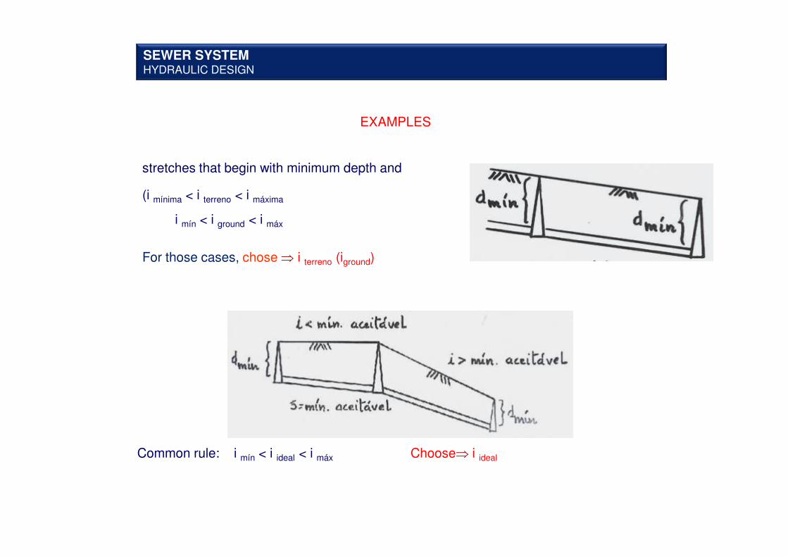
stretches that begin with minimum depth and
(i mínima < i terreno < i máxima
i mín < i ground < i máx
For those cases, chose ⇒ i terreno (iground)
Common rule: i mín < i ideal < i máx Choose⇒ i ideal
EXAMPLES
SEWER SYSTEMHYDRAULIC DESIGN

SANEAMENTO / FEVEREIRO DE 2012 131
Choose ⇒ i mín
Choose ⇒ i máx
SEWER SYSTEMHYDRAULIC DESIGN
EXAMPLES

SANEAMENTO / FEVEREIRO DE 2012 132
SEWER LONGITUDINAL PROFILE
SEWER SYSTEMHYDRAULIC DESIGN
SANEAMENTO / FEVEREIRO DE 2012 133
1. Diameter size in wastewater separate systems must not decrease from upstream to
downstream
2. For unitary or storm water separated systems, the reduction of the section downstream
may be reduced, as long as the transport capacity is maintained
[Decreto Regulamentar nº 23/95 – Artigo 159º]
� the insertion of one pipe into another must be done according to the flow direction;
� pipes with different diameter must be aligned by the upper part (to avoid hydraulic
jump, clogging and ensure the continuity of the flow)
� Soft drops (gap≤0,5 m) or guided drops (gap>0,5 m)
� if the depth of a manhole is >5m a platform must be built halfway, with non matching
stairs or passage.
DIAMETERS AND OTHER RULES FOR THE DESIGN OF THE LONGITUDINAL PROFILE
[Decreto Regulamentar nº 23/95 – Artigo 135º]
SEWER SYSTEMHYDRAULIC DESIGN

SANEAMENTO / FEVEREIRO DE 2012 134
1. Minimum depth of pipes is 1m and it is relative to the top of the
pipe.
INSTALLATION AND LAYOUT OF PIPES
[Decreto Regulamentar nº 23/95 – Artigo 137º]
The mentioned minimum depth can be increased depending on traffic demands or due to
the connection to households or other infrastructures.
Only for exceptional situations depths lower than the minimum may be allowed as long as
the protection of the pipes is guaranteed
[Decreto Regulamentar nº 23/95 – Artigo 24º]
3. Water distribution pipes must be placed at least 1 m above wastewater drainage pipes,
in order to prevent contamination. If this is not possible, adequate protection must be
ensured.
SEWER SYSTEMLOCATION AND LAYOUT OF PIPES

SANEAMENTO / FEVEREIRO DE 2012 135
� On top view, the wastewater pipe and the storm water must maintain the
same relative position (wastewater pipe to the right or to the left of the
storm water pipe)
� In the longitudinal profile the lower part of the storm water pipe must be
placed at a higher elevation than the upper part of the wastewater pipe.
� In the cross-sectional profile minimum distances must be set between the
wastewater pipe and the storm water pipe, both horizontally and vertically.
� In crossings, junctions and direction changes the manholes should be
placed according to the Figure on the lower left.
LOCATION AND LAYOUT OF PIPES
SEWER SYSTEMLOCATION AND LAYOUT OF PIPES
SANEAMENTO / FEVEREIRO DE 2012 136
SISTEMAS DE DRENAGEM DE ÁGUAS RESIDUAIS
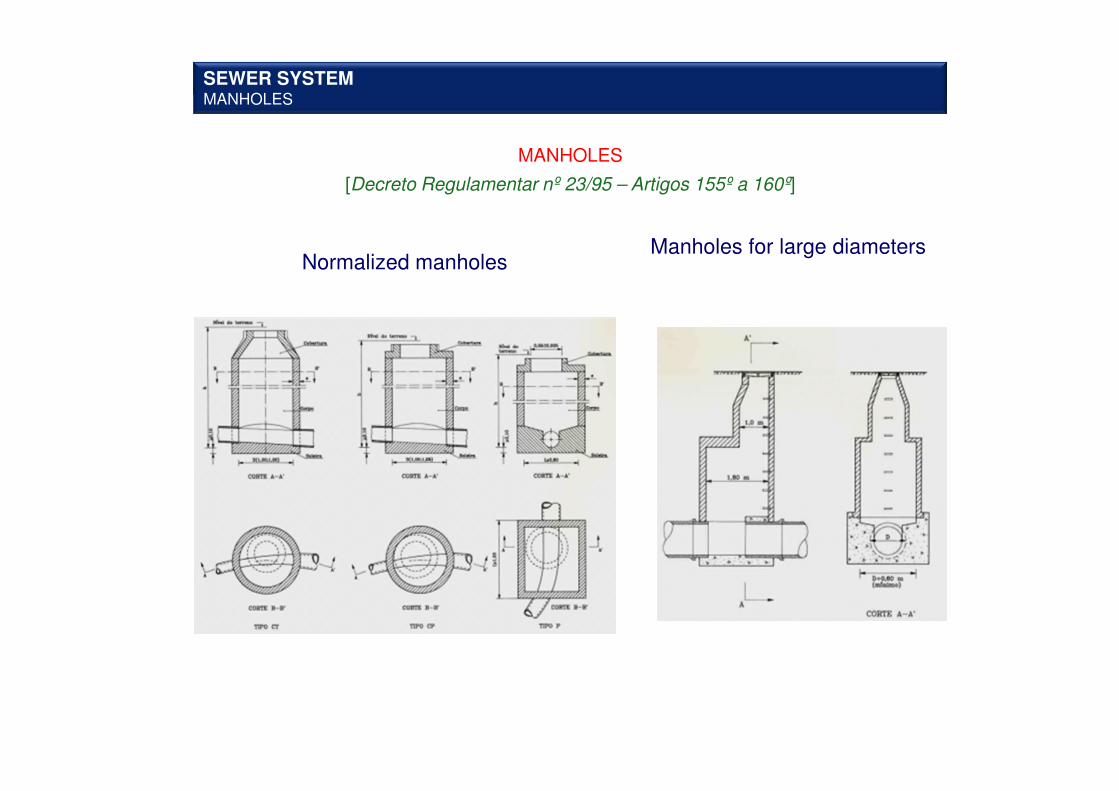
Normalized manholesManholes for large diameters
MANHOLES
[Decreto Regulamentar nº 23/95 – Artigos 155º a 160º]
SEWER SYSTEMMANHOLES

SANEAMENTO / FEVEREIRO DE 2012 137
Manholes with inner diameter (D i) depending on
the dept (H)
H < 2,5 m D i = 1,00 m
H > 2,5 m D i = 1,25 m
MANHOLES: BODY AND OPENING
SEWER SYSTEMMANHOLES

SANEAMENTO / FEVEREIRO DE 2012 138
MANHOLES: BOTTOM, SOFT DROPS AND GUIDED DROPS
SEWER SYSTEMMANHOLES
Initial or passage manhole
Circular manhole for direction change without drop
Rectagular manhole for direction change without drop

SANEAMENTO / FEVEREIRO DE 2012 139
SEWER SYSTEMMANHOLES
MANHOLES: BOTTOM, SOFT DROPS AND GUIDED DROPS
Passage manhole with a drop Junction chamber with drop

SANEAMENTO / FEVEREIRO DE 2012 140
MANHOLES: CLOSING MECHANISM AND NORMALIZED STEPS
SEWER SYSTEMMANHOLES

SANEAMENTO / FEVEREIRO DE 2012 141
MANHOLE WITH A SWEPING FLOW
[Decreto Regulamentar nº 23/95 – Artigo 161º]
SEWER SYSTEMMANHOLES

SANEAMENTO / FEVEREIRO DE 2012 142
CONSTRUCTION DETAILS
[Decreto Regulamentar nº 23/95 – Artigos146º a 154º]
SEWER SYSTEMCONNECTION BRANCHES
SANEAMENTO / FEVEREIRO DE 2012 143
Lesson 12
SANITARY ENGINEERINGLESSON 11 / SUMMARY
STORMWATER DRAINAGE SYSTEMS AND WATER QUALITY
�Main system components
�Plant layout. Source control techniques
�Design steps: baselines, design flows
�Hydraulic design
�Common and special infrastructures of stormwater systems
�Kinds of pollutants and effluents on receiving waters

SANEAMENTO / FEVEREIRO DE 2012 144
infiltração
no solo
armazenamento
em depressões
intercepção +
evapotranspiração
escoamento
superficial
intercepção +
evaporação
escoamento
em colectores
evaporação
STORMWATER PLANNING AND DESIGN
ORIGIN AND DESTINATION
a) A fraction does not reach the ground(is intercepted or evaporate)
b) Another fraction reaches permeable soil
. Part infiltrates
. Part evaporates (after puddling)
. Part flows (direct runoff)
c) The remaining portion falls into impervious area (roads and pavements, pavements and roofs)
STORMWATER DRAINAGE SYSTEMSStormwater origin in urban areas
Interception + Evaporation
Interception +
Evapotranspiration
Evaporation
Superficial
evaporation
Water puddle
Infiltration
Pipe flow

SANEAMENTO / FEVEREIRO DE 2012 145
� Concerns in urban areas
a) Pollutant load of stormwater
► Heavy metals(Fe, Pb, Zn,…)► hydrocarbons► Suspended solids► CBO5 (organic matter)
► Unitary systems ⇒⇒⇒⇒ “first flush” effect (resuspension and transportof pollutants previously decanted into collecting)
b) Unitary behaviour of domestic (even when conceived as separative)
c) Large range and variability of flows
► Stormwater peak flows >> household flows► Strong relationship between soil occupation and flow
– � impermeable areas– Artificial water channels
► Transient flow in pipes
PROJECT MORE COMPLEX AND EXPENSIVE
Increased flows
STORMWATER DRAINAGE SYSTEMSStormwater origin in urban areas

SANEAMENTO / FEVEREIRO DE 2012 146
MAIN GUIDELINES FOR STORMWATER DRAINAGE SYSTEMS
a) Goal 1- Reduce peak flow
b) Goal 2 – Water quality control
Main goal: Reduce the risc of flooding in urban areas
STORMWATER DRAINAGE SYSTEMSDesign and establishmentof systems
a1) Increase interception
a2) Increase filtration
a3) increase storage and detention
a4) increase flow travel time
a5) apply adequate operational and management techniques
b1) Avoid discharge in sensitive areas
b2) treat flows ⇒⇒⇒⇒ overland flowpond/constructed wetlands systemshydrodinamic separators/physico-chemical systems/UV desinfection

SANEAMENTO / FEVEREIRO DE 2012 147
Examples of flooding in Portugal
Flooding in Albufeira, Oct. 2009 and
Alcântara, in Lisbon, Feb. 2008
Flash floods in Madeira, February 2010
STORMWATER DRAINAGE SYSTEMSManagement of urban drainage systems - challenges and perspectives

SANEAMENTO / FEVEREIRO DE 2012 148
CONTROL PROCEDURES (QUANTITY AND QUALITY)
STORMWATER DRAINAGE SYSTEMSDesign and implementation of systems
a1) Vegetation
a2) Introduce green areas in the the middles of paved areas
• Use of pourous materials in pavments
• Use drains
• Use draining chambers
a3) Use retention and detention basins
• Use storage tanks at dwelling level
a4) Reduce the lenght of pipes and increase the travel time in the upper catchments (with limitations)
a5) Real time control (use the installed storage capacity)
SANEAMENTO / FEVEREIRO DE 2012 149
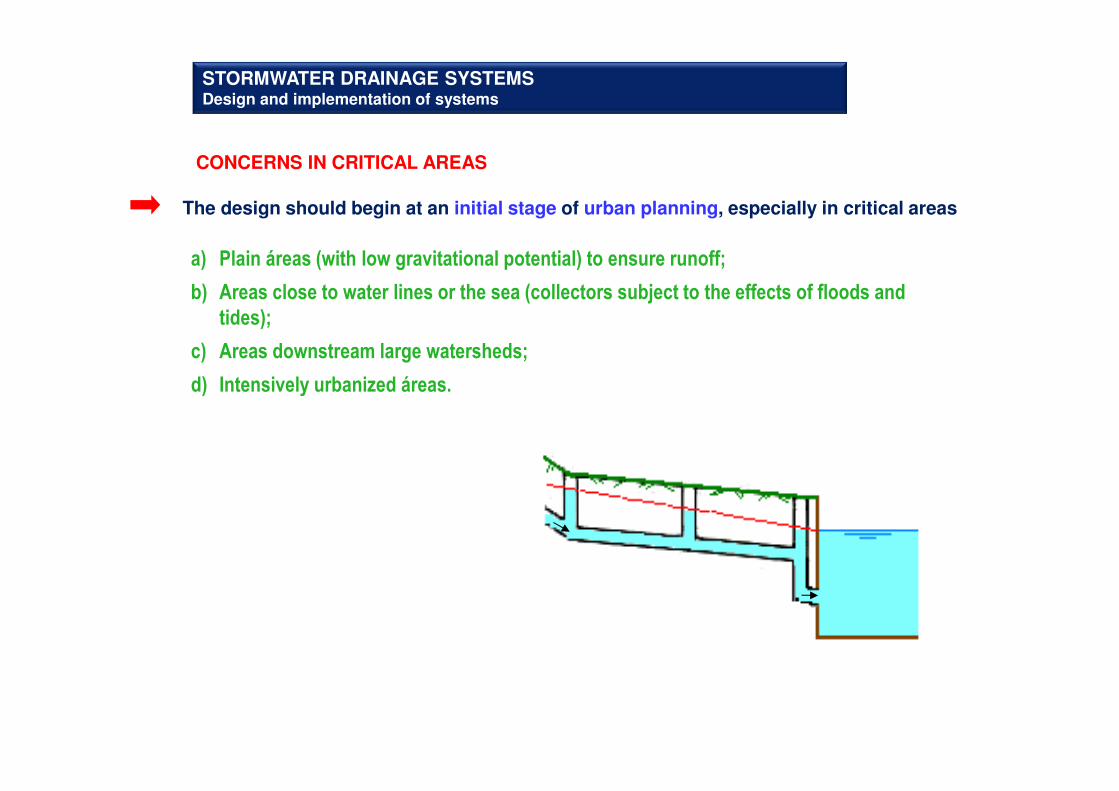
The design should begin at an initial stage of urban planning, especially in critical areas
CONCERNS IN CRITICAL AREAS
a) Plain áreas (with low gravitational potential) to ensure runoff;
b) Areas close to water lines or the sea (collectors subject to the effects of floods and
tides);
c) Areas downstream large watersheds;
d) Intensively urbanized áreas.
STORMWATER DRAINAGE SYSTEMSDesign and implementation of systems

SANEAMENTO / FEVEREIRO DE 2012 150
• Reduction of pipe lenght and diameters (Decree nº23/95 – Article 118°°°°; point 3 and 4)
a) Maximize the surface path (especially in the headwaters)
b) Promote the integration of permeable areas (green areas, porous pavement ...)
• Concern about the quality of the receiving water bodies (due to pollution transmitted by the stormwater flows, especially after dry periods)
GENERAL CONCERNS:
STORMWATER DRAINAGE SYSTEMSDesign and implementation of systems

SANEAMENTO / FEVEREIRO DE 2012 151
• Adoption of non conventional drainage solutions
SOURCE CONTROL TECHNIQUES
Vegetated swales Retention /infiltration basin
(Regateira, Almada).
Infiltration trenches
STORMWATER DRAINAGE SYSTEMSSource control techniques

SANEAMENTO / FEVEREIRO DE 2012 152
Wet detention basin Dry detention basin
Pourous pavements
STORMWATER DRAINAGE SYSTEMSSource control techniques

SANEAMENTO / FEVEREIRO DE 2012 153
PLANT LAYOUT AND CATCHMENT LIMITS
� Pipes intalled in the middle of the street (as household collectors)
� Carefull delimitation of subcatchments affected to each network section
Upper subcatchment
subcatchment
Stormwater Collector
Receiving environment
STORMWATER DRAINAGE SYSTEMSPlant layout

SANEAMENTO / FEVEREIRO DE 2012 154
STEPS OF THE DESIGN PROCESS
1. Definition of baselines
2. Calculation of design flows
3. Hydraulic design
1. DEFINITION OF BASELINES
• Delimitation of the basin limits and sub-basins affected to each network section
• Definine the return period T (normally varies between 2 and 25 yrs) –
• Determination of local rain regime ⇒⇒⇒⇒ IDF curves
• Characterization of subcatchments (area, runoff coeficiente, slope, soil type, % impervious áreas, etc)
• Determine initial concentration times tc
(Decree nº 23/95 –Article 130°°°°)
STORMWATER DRAINAGE SYSTEMSDesign steps

SANEAMENTO / FEVEREIRO DE 2012 155
• Identify constraints:
- Elevations and water level in the receiving environment;
- Elevation of the lower areas to drain;
- Crossings and intersections with other infrastructure.
2. CALCULATION OF STORMWATER DESIGN FLOWS
� Rational Method (semi-conceptual; Mulvaney, 1851 e Kuickling, 1889)
Qstw = C x I x A
sendo:
Qstw - Stormwater flow to be drained by the collector (m3/s)
C - runoff coeficient (-) ⇒
I - precipitation intensity (m3/(ha.s))
A - área of the catchment (ha)
(Decree nº 23/95 – Article 129°°°°)
STORMWATER DRAINAGE SYSTEMS
SANEAMENTO / FEVEREIRO DE 2012 156
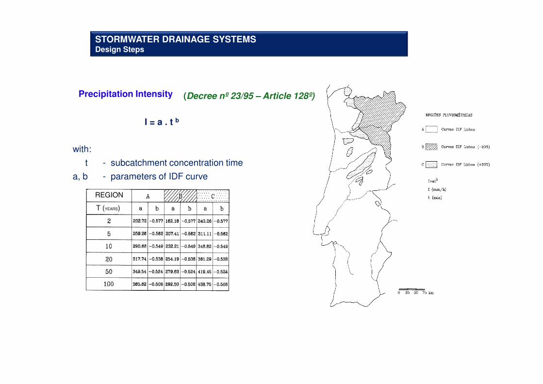
Precipitation Intensity
I = a . t b
with:
t - subcatchment concentration time
a, b - parameters of IDF curve
(Decree nº 23/95 – Article 128º)
STORMWATER DRAINAGE SYSTEMSDesign Steps
REGION
T (YEARS)

SANEAMENTO / FEVEREIRO DE 2012 157
� Método Racional Generalizado (Costa, 1956, D.R. nº 23/95-Anexo X)
AICt
t
V
V Q
c
⋅⋅⋅⋅⋅⋅= γ1
2
sendo,
V1 - volume corresponding to the rising part ofthe hydrograph (m3)
V - total volume of the hydrograph (m3)t - duration of the design precipitation (h)tc - concentration time of the catchment (h)γ - Backwater coefficient.
2 V1/V - Represents the retention and storage: minimal in natural catchments and maximal for impervious catchments (=1).
t/tc - Represents the lag between the end of the precipitation and the instant of peak flow: itis minimal in natural catchments (=0,7) and it is assumed equal to 1 for impervious catchments or highly piped.
STORMWATER DRAINAGE SYSTEMSDesign Steps
= C1 I A

SANEAMENTO / FEVEREIRO DE 2012 158
Global reduction coefficient of the generalized rational method (Qp = C1 I A):
C1 = C (2 v1/v) (t/tc)
STORMWATER DRAINAGE SYSTEMSDesign Steps

SANEAMENTO / FEVEREIRO DE 2012 159
3. HYDRAULIC DESIGN
• Maximum flow depth ⇒⇒⇒⇒ (h/D) ≤≤≤≤ 1
• Maximum flow velocity ⇒⇒⇒⇒ Vmáx = 5 m/s (for unitary or separative stomwatercollectors)
• Minimum flow velocity ⇒⇒⇒⇒ Vmín = 0,9 m/s
Self-cleaning criteria
• Minimal depths (Art. 137) ⇒⇒⇒⇒ Depths ≥ 1 m
• Minimum diameter (Art. 134) ⇒⇒⇒⇒ Dmín = 200 mm
• Minimum and maximum slopes ⇒⇒⇒⇒ 0,3% e 15% (por razões construtivas)
A – PROJECT CRITERIA:
J mín = 1/ D (mm) Norma Europeia
When these limits are unviable, (common in
the upper subcatchments) the slopes should
be chosen to ensure these limits for full section
flow
(Decree nº 23/95 – Article 133º)
STORMWATER DRAINAGE SYSTEMSDesign Steps

SANEAMENTO / FEVEREIRO DE 2012 160
B – CALCULATION STEPS
1 - Analyse the project area and the network plan layout.
Identify constraints ⇒⇒⇒⇒ (Elevations and water level in the receiving environment; Crossings and intersections with other infrastructures …)
2 - Define the return period, T.
3 - Select the IDF curve for the study area and the chosen return period.
4 - Define subcatchments for each design section ⇒⇒⇒⇒ calculate the respective area A
5 - Determine the overall average weighted coefficient for the catchment for each design section:
C = (∑i CiAi) / ∑i Ai
6 - Determine initial concentration times, t c
pe c t t t +=t
L
Vp
j
j
= Σ
STORMWATER DRAINAGE SYSTEMSCalculation Steps
Land SlopeA I < 50% A I > 50%
(min) (min)
very high 5.0 5.0
high 10.0 7.5
medium and plain 15.0 10.0

SANEAMENTO / FEVEREIRO DE 2012 161
I = a . t b
7 - Determine the average precipitation intensity, I, for a duration equal to tc (based on IDF curves)
8 - Calculate design flow, using the following expression (rational method):
Q p = ∑i C i x A i x I
9 - Choose a diameter and the pipe slope:
minimize costs; minimal seating depth; verify hydraulics criteria
10 - Determine the velocity, flow depth and the drag tension in the collector;
11- Determine the travel time, tp, for the section considered on the previous point;
12- Add the tp calculated with the concentration time calculated on step 6;
13- Repeat all the steps starting at step 5, from upstream to downstream for each section.
STORMWATER DRAINAGE SYSTEMSCalculation Steps

SANEAMENTO / FEVEREIRO DE 2012 162
COMMON COMPONENTS OF STORMWATER SYSTEMS
1- Public sewers (circular, in concrete or PVC)
2- Manholes (for inspection, operation and maintenance)
3- House connections
4- Inlets
Gutters Floor drains Combined gutter-floor drain systems
a) Straight lines between manholes
b) Implementation of water distribution pipelines within the paved driveway, in the middle of the street ( Pimin = 1 m)
c) Smaller lenghts than domestic network
d) Final disposal (river, …)
STORMWATER DRAINAGE SYSTEMSFittings and accessories

SANEAMENTO / FEVEREIRO DE 2012 163
Curb inletDrain inlet
STORMWATER DRAINAGE SYSTEMSFittings and accessories

SANEAMENTO / FEVEREIRO DE 2012 164
SPECIAL COMPONENTS
1- Retention Ponds
2- Infiltration chambers
3- Sand Traps
- conventional (rectangular)
- non conventional (circular, …)
4- Pumping Stations
Should be avoided when possible Construction and exploration costs;
Magnitude and randomness of flows.
(D50 ≥ 0,2 mm), (V = 0,30 m/s)
STORMWATER DRAINAGE SYSTEMSFittings and accessories
HEADWORKS OUTLET WORKS
INTERNAL CHANNEL

SANEAMENTO / FEVEREIRO DE 2012 165
RETENTION BASIN
�Objectives
• Reduce risk of floods
• Creation of recreational areas (for fishing and boating…)
• Creation of water reserves (agriculture, fire fighting, industries, irrigation…)
• Protection of the environment (reduction of TSS e organic mater)
(Decree nº23/95 – Article 176°°°°)
STORMWATER DRAINAGE SYSTEMSRetention Basins
� Types of basins:
- underground basins (reservoirs)
- open basins - dry
- with permanent water level

WATER POLLUTION AND PUBLIC HEALTH:
POLLUTION:
Presence of substances in water that interfere in its use .
WTP:Ensure water quality for human consumption.
WWTP:
Ensure that the effluent is compatible with the capacity of the receiving water.
Receiving waterIntake ofwater
Discharge
WWTPWastewatertreatment plant
WTPWater treatmentplant
Water Supply Network SewerageNetwork
ReservoirWater Consumption(households, industries,...)
Sanitation [166]
Related Documents