TEST METHOD FOR EARTHWORK COMPACTION CONTROL BY SAND CONE OR VOLUMETER APPARATUS GEOTECHNICAL TEST METHOD GTM-9 Revision #3 AUGUST 2015

Sand corn test
Dec 10, 2015
Geo technical practical
Welcome message from author
This document is posted to help you gain knowledge. Please leave a comment to let me know what you think about it! Share it to your friends and learn new things together.
Transcript

TEST METHOD FOR EARTHWORK
COMPACTION CONTROL BY SAND CONE OR VOLUMETER APPARATUS
GEOTECHNICAL TEST METHOD
GTM-9 Revision #3
AUGUST 2015


EB 15-025 Page 1 of 13
GEOTECHNICAL TEST METHOD:
TEST METHOD FOR EARTHWORK COMPACTION CONTROL BY
SAND CONE OR VOLUMETER APPARATUS
GTM-9
Revision #3
STATE OF NEW YORK
DEPARTMENT OF TRANSPORTATION
GEOTECHNICAL ENGINEERING BUREAU
AUGUST 2015
EB 15-025 Page 2 of 13
TABLE OF CONTENTS
1. SCOPE .................................................................................................................................3
2. SUMMARY OF METHOD .................................................................................................3
3. EQUIPMENT.......................................................................................................................3
4. EQUIPMENT CALIBRATION ...........................................................................................5
4.1 Sand Cone Apparatus Volume Correction ...............................................................5
4.2 Sand Calibration Factor ...........................................................................................5
4.3 Volumeter ................................................................................................................6
5. TEST PROCEDURE ...........................................................................................................7
5.1 Test Location Data ...................................................................................................7
5.2 Testing and Sampling ..............................................................................................7
5.3 Determination of Plus ¾ in. (19 mm) Material and Moisture Content ....................9
5.4 Control Density ......................................................................................................11
APPENDIX ....................................................................................................................................13
A. Sand Cone Apparatus Drawing SM 1685 ........................................................... A-1
Density Cylinder Drawing SM 1563 ................................................................... A-2
B. Sand Density Calibration - Form SM 85 R1 ........................................................ B-1
C. Density Correction Curves Plus 3/4" (19 mm) Material
Specific Gravity 2.60 - Figure 1 ...........................................................................C-1
D. Compaction Control Curves - Family 1 and Family 2 ........................................ D-1
E. Field Compaction Sheet - Sand Cone or Volumeter Apparatus -
Form SM 417b ..................................................................................................... E-1

EB 15-025 Page 3 of 13
1. SCOPE
This test method describes the procedure for determining the in-place density and moisture of
earthwork through the use of a sand cone or volumeter apparatus. This method may be used in
conjunction with either the Standard (AASHTO T-99) or Modified Proctor (AASHTO T-180)
Density Test for determining the percent of Maximum Density.
The details included in this test method are for use with the Standard Proctor Test.
2. SUMMARY OF METHOD
The test consists of the following steps which are explained in the test procedure:
- Determining the Wet Density
- Determining the Moisture Content
- Calculating the Dry Density
- Determining the Maximum Density
- Calculating the percent of Maximum Density
3. EQUIPMENT
a. Sand Cone Apparatus: The sand cone apparatus consists of a container for the
calibrated sand; a conical, stopcock-controlled outlet; and a base plate. The base of
the conical outlet shall have a nominal interior diameter of 6 in. (150 mm), and shall
be flared flat to fit the base plate. The base plate and container are matched and
fitted; they are not to be interchanged with other units. The sand container shall be
capable of holding no less than 8 lbs. (3.6 kg) or 1 ft.3 (0.028 m
3) of calibrated sand.
See Geotechnical Engineering Bureau Drawing No. SM 1685 (Appendix A) for an
acceptable apparatus.
Volumeter: The sand cone displacement volumeter with its matching base plate
may be substituted for the sand cone apparatus. The volumeter has been calibrated
to read volume directly as opposed to the sand cone apparatus which requires a
conversion from weight to volume.
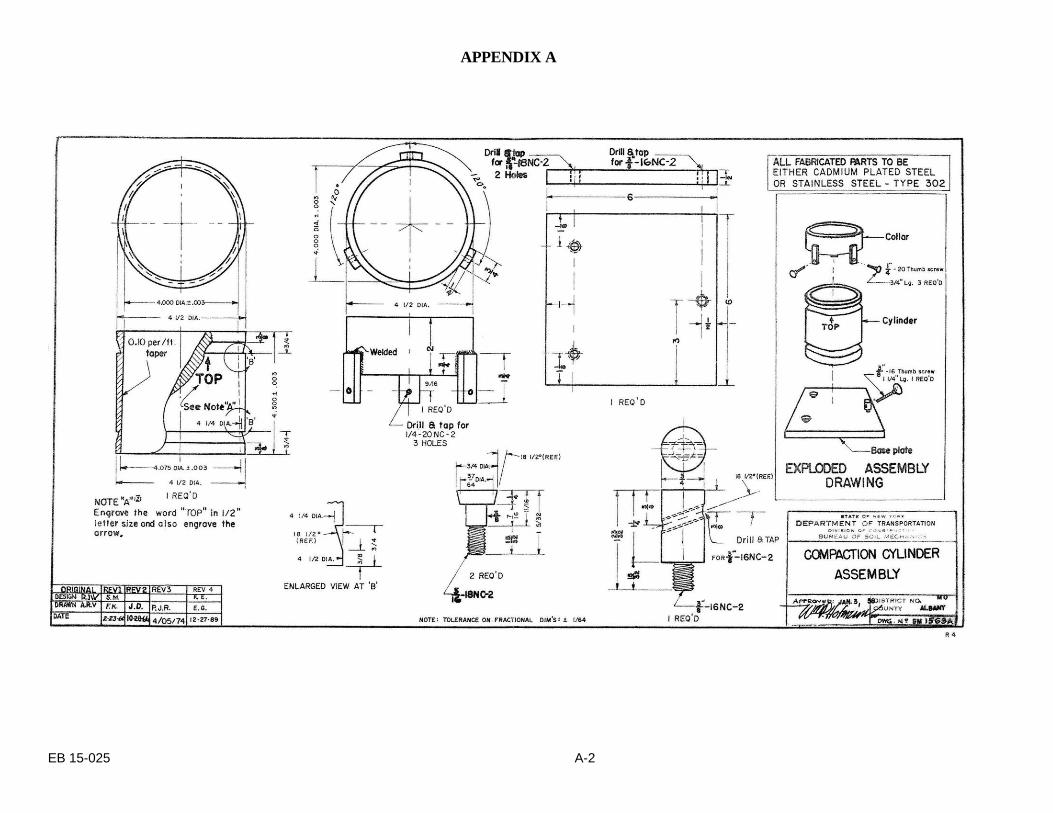
b. Density Cylinder: 1/30 ft.3 (944 cm
3) volume, in accordance with AASHTO
Standard Density Test T-99 or Geotechnical Engineering Bureau Drawing No. SM
1563A (Appendix A).
c. Rammer: Refer to AASHTO T-99 or T-180.
d. Scale: Minimum of 30 lb. (13.6 kg) capacity to weigh directly to the nearest 0.01 lb.
(5 g).

EB 15-025 Page 4 of 13
e. Balance: Approximately 1600 g capacity, to weigh directly to the nearest 0.1 g.
f. Steel Straight Edge: 9 to 12 in. (230 mm to 300 mm).
g. Gas or Electric Stove.
h. Sieve: ¾ in. (19 mm).
i. Pail: 10 qt. (9.5 L) size or larger.
* j. Knife: Butcher.
* k. Hammer: 1 lb. (0.5 kg) minimum weight.
* l. Chisel: 1 in. (25 mm) blade width by 9 in. (230 mm) length.
* m. Skillet: 12 in. (300 mm) diameter.
n. Spoon: Basting type.
* o. Spatula: 6 in. (150 mm) length of blade.
p. Cans: Friction top with covers, 1 gal (3.7 L) size.
* q. Pans: 24 in. (600 mm) square and 3 to 4 in. (75 mm to 100 mm) high.
r. Tares: Numbered cake pans or pie plates for moisture content determinations.
s. Paint Brush: 2 in. (50 mm) size.
t. Calibrated Sand: Clean dry sand.
(a) Standard Ottawa Sand;
or (b) Washed sand passing the No. 20 (0.85 mm) sieve and retained on the No. 40
(0.425 mm) sieve;
or (c) Flint Shot Grade, Size 2Q.
u. Calibrated Container: Having a capacity of 0.1 ft.3
(2832 cm3), an inside diameter
of 6 in. (150 mm) and an inside height of 6.1 in (155 mm): used for calibrating the
sand.
v. Compaction Control Curves: Family 1 and Family 2, (3 sheets) dated 02/28/77,
see Appendix D.
w. Plus ¾ in. (19 mm) Correction Curve: A curve for a specific gravity of 2.60 is
included. See Appendix C. Curves for other specific gravities are available from the
Regional Geotechnical Engineer.
x. Form SM 417: Field Compaction Sheet, sand cone or volumeter apparatus
(Appendix E).
* The equipment annotated by asterisks are not essential, but are considered desirable.
EB 15-025 Page 5 of 13
4. EQUIPMENT CALIBRATION
4.1 Sand Cone Apparatus Volume Correction
A portion of the sand released from the sand cone apparatus during the test remains in the
cone. The apparatus volume correction is the weight of this material. This correction value
must be determined for each sand cone apparatus and is usually furnished by the Regional
Geotechnical Engineer. Form SM 85 R1 – Sand Density Calibration (Appendix B), may be
used for the sand cone apparatus volume correction and the sand calibration factor (Section
4.2). It is determined in the following manner:
- Avoid all vibrations of the equipment while filling or emptying the apparatus.
- On a level surface, fill the apparatus with sand through the cone at a uniform rate until
sand stops.
- Close the stopcock carefully and pour off the excess sand remaining in the cone.
- Weigh the filled sand cone apparatus.
- Invert the sand cone apparatus on the base plate on a smooth and level surface such as a
table.
- Open the stopcock and allow the sand to flow out of the apparatus. Do not allow any
sand to spill outside of the cone during this operation.
- Close the stopcock after the flow of sand has stopped.
- Remove and weigh the sand cone apparatus.
The difference in weight is the Apparatus Volume Correction – lbs. This value will remain
constant for each apparatus unless the cone subsequently becomes dented or the calibrated
sand changes. If the cone becomes dented or the calibrated sand changes, the apparatus
volume correction must be re-determined.
4.2 Sand Calibration Factor
The sand calibration factor is the loose unit weight of the calibrated sand. The Regional
Geotechnical Engineer will normally furnish this value. It is determined in the following
manner:
- Weigh a filled sand cone apparatus.
- Place the matched base plate over a calibrated container of known volume. Invert
the filled sand cone apparatus on the base plate.
- Open the stopcock until the sand tops flowing.
- Close the stopcock.
- Weigh the sand cone apparatus.
- Subtract the second weight and the apparatus volume correction from the first
(filled) weight.
- Divide the difference in weights by the known volume of the calibrated container.
This value is the Sand Calibration Factor – pcf. It should remain constant.
EB 15-025 Page 6 of 13
The sand calibration factor and the apparatus volume correction must be for the calibrated
sand actually being used for the test. Any time the sand supplied changes or there is any
reason to suspect a difference in material, then both the Apparatus Volume Correction and
the Sand Calibration Factor must be re-determined.
4.3 Volumeter
The volumeter and matching base plate have been calibrated. No additional calibration is
required even if the appearance of the sand changes.
To fill the volumeter:
a). Make sure the volumeter is empty.
b). Set the volumeter with the stopcock open on a firm, level area with the cone end
up.
c). Fill the plastic container completely by pouring the sand into the cone. Keep the
cone full until the sand stops flowing into the container.
d). Close the stopcock carefully and pour off the excess sand remaining in the cone.
e). If the volumeter is subject to movement or vibration during the filling operation or
the closing of the stopcock, remove all the sand and start over.
f). At no time should the cone portion of the volumeter be removed from the cylinder.
Removal or displacement by tightening or loosening of the cone will affect the
calibration.
Keep the reserve container of sand covered (while not taking sand from it) to keep the sand
from picking up moisture from the air.
As the volumeter is handled and transported, the sand will compact, and its level within the
volumeter will drop.
Do not add more sand. The measurement of the volume of the hole by the volumeter is
based on loose volume of sand.
Damaged volumeters and/or base plates should be immediately removed from service.
Volumeters which have been supplied by the Geotechnical Engineering Bureau and become
damaged shall be returned to the Bureau.

EB 15-025 Page 7 of 13
5. TEST PROCEDURE
Form SM 417b is used for recording the compaction test data. Refer to this form in Appendix E.
Enter the required project information at the top of the form. Gs – Bulk Saturated Surface Dry shall
be assumed to be 2.60 unless otherwise directed by the Regional Geotechnical Engineer.
Form SM 417b uses US Customary Units (lbs.) for recording the larger weights (sand & apparatus,
sand, Plus ¾ in. (19 mm) Material, etc.) and International System of Units (g) for recording the
smaller weights (soil & tare, tare, etc.).
5.1 Test Location Data
LINES
1 - Date of Test.
2 - Test No.: Tests for a project shall be numbered as required by MURK.
3 - Station of Test: The location of the test should be determined accurately.
4 - Offset: The location of the test should be determined accurately.
5 - Location: The required percent of maximum density for the material
depends on its location. Indicate whether the test is performed in the
embankment, in the subgrade area, at a structure location or at another area
with specific compaction requirements.
6 - Soil Type: Briefly describe the material tested so that the appropriate
Family of Compaction Control Curves is used.
5.2 Testing and Sampling
The sand cone apparatus is used to determine the volume of the test hole. Fill the apparatus
with calibrated sand and weigh it. The scale and balance must be leveled and properly
adjusted before any weighing are made. The volumeter may also be used for this
determination, in which case weighing is not necessary.
Remove all loose and disturbed material at the test location. Level a small area and set the
base plate firmly in place. Dig a hole through the opening in the plate, approximately equal
in diameter to the hole in the base plate, and to a depth of approximately 6 in. (150 mm).
The desired volume of the hole is about 0.1 ft.3 (2832 cm
3). The volume should never be
less than 0.06 ft.3 (1700 cm
3). The hole should be dug rapidly and all removed material
immediately placed in a previously weighed friction top can. The can should be covered to
keep moisture loss from the sample to a minimum. Any material loosened during the
digging operation should be removed from the hole and placed in a friction top can. The
calibrated sand must completely fill the hole. Care should be exercised to avoid

EB 15-025 Page 8 of 13
undercutting of the base plate and abrupt projections of embedded materials into the hole.
Projections inhibit the proper filling of the hole with the calibrated sand which causes errors
in the determination of the hole volume. If any of the above criteria are not met, the test is
void.
Set the sand cone apparatus or volumeter on the base plate over the hole. Open the stopcock
to permit the sand to flow into the hole. Traffic and equipment in the vicinity of the test area
should be stopped while the stopcock is open. Vibrations will compact the flowing sand in
the hole resulting in an incorrect test value. After the sand stops flowing, close the stopcock
and remove the apparatus.
When using the sand cone apparatus weigh the apparatus with the sand remaining in it. Do
not refill the sand cone apparatus until after this weight has been recorded.
If the volumeter is used, hold the closed volumeter vertically with the cone end up. Invert
the volumeter momentarily and return to the original position. Gently shake (do not jar) the
apparatus just enough to level the sand. From the scale indicators on the container, read the
top surface of the sand to the nearest 0.001 ft.3. Repeat 2 times. Record the average of the 3
readings on Line H of the Compaction Control Work Sheet. (No individual reading should
be greater than 0.001 ft.3 more or less, than the average of the 3 readings.
Note: The volumeter must be emptied of all remaining sand before it is refilled for another
test.
Additional soil may be required for use later in the test procedure. This soil should be
removed from the area immediately adjacent to, and at the same elevation, as the test hole.
Place this material in a separate friction top can. Material should never be added to the
sample obtained from the density hole.
Enter the data on the appropriate lines on Form SM 417b. Lines A through G are omitted if
the volumeter type of apparatus is used.
LINES
A - Wt. Sand & Apparatus (Before) – lbs.
B - Wt. Sand & Apparatus (After) – lbs.
C - Wt. Sand Used – lbs. (A – B)
D - Apparatus Volume correction – lbs.
E - Wt. Sand in Hole (Net) – lbs. The Wt. Sand Used minus the Apparatus
volume correction. (C – D).
F - Sand Calibration Factor (pcf).

EB 15-025 Page 9 of 13
G - Volume of Hole (ft.3). The volume of the hole is calculated by dividing the
net weight of sand used to fill the hole by the Sand Calibration Factor. The
volume should be computed to four decimal places. (E ÷ F).
H - Volume of Hole (ft.3) Volumeter. The volume of the hole may be read
directly when using the volumeter. In this case, omit Lines A through G and
enter this value on Line H.
J - Wt. Soil & Friction Top Can – lbs.
K - Wt. Friction Top Can – lbs. The weight of the friction top can is entered on
this line. Since this weight is constant, it is convenient to weight it at some
time prior to the test and write this weight on the matched can and top.
L - Wt. of Soil – lbs.
M - Wet Density Field (Total) pcf. The wet in-place density of the total sample is
calculated by dividing the weight of soil by the volume of hole.
(L ÷ G) or (L ÷ H).
5.3 Determination of Plus ¾ in. (19 mm) Material and Moisture Content
In order to evaluate the field density it must be compared to a control density. The control
density is expressed in terms of the dry density of the minus ¾ in. (19 mm) portion of the
material. The method of determining the control density is described in Section 5.4.
The field density, Line M, is in total wet density units. In order to compare it to the control
density (minus ¾ in. (19 mm) dry units) the percentage of plus ¾ in. (19 mm) material must
be determined. These values are then used to correct the wet density field (total) Line M
into the proper units for comparison. Separate the sample on the ¾ in. (19 mm) sieve and
proceed as follows:
Plus ¾ in. (19 mm) material (field sample):
LINES
N - Wet Wt. Plus ¾ in. (19 mm) & Tare – lbs.
P - Wt. of Tare – lbs. This weight shall be predetermined, written on the tare
and periodically checked.
Q - Wet Wt. Plus ¾ in. (19 mm) – lbs. (N – P)
EB 15-025 Page 10 of 13
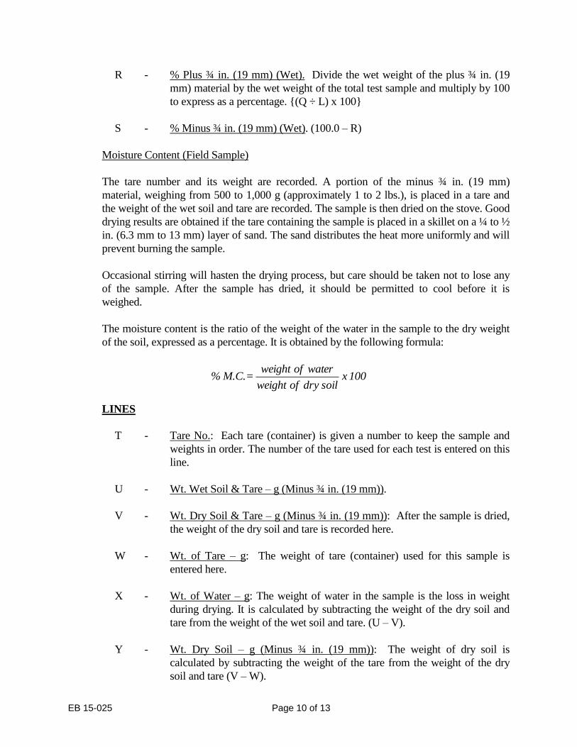
R - % Plus ¾ in. (19 mm) (Wet). Divide the wet weight of the plus ¾ in. (19
mm) material by the wet weight of the total test sample and multiply by 100
to express as a percentage. {(Q ÷ L) x 100}
S - % Minus ¾ in. (19 mm) (Wet). (100.0 – R)
Moisture Content (Field Sample)
The tare number and its weight are recorded. A portion of the minus ¾ in. (19 mm)
material, weighing from 500 to 1,000 g (approximately 1 to 2 lbs.), is placed in a tare and
the weight of the wet soil and tare are recorded. The sample is then dried on the stove. Good
drying results are obtained if the tare containing the sample is placed in a skillet on a ¼ to ½
in. (6.3 mm to 13 mm) layer of sand. The sand distributes the heat more uniformly and will
prevent burning the sample.
Occasional stirring will hasten the drying process, but care should be taken not to lose any
of the sample. After the sample has dried, it should be permitted to cool before it is
weighed.
The moisture content is the ratio of the weight of the water in the sample to the dry weight
of the soil, expressed as a percentage. It is obtained by the following formula:
LINES
T - Tare No.: Each tare (container) is given a number to keep the sample and
weights in order. The number of the tare used for each test is entered on this
line.
U - Wt. Wet Soil & Tare – g (Minus ¾ in. (19 mm)).
V - Wt. Dry Soil & Tare – g (Minus ¾ in. (19 mm)): After the sample is dried,
the weight of the dry soil and tare is recorded here.
W - Wt. of Tare – g: The weight of tare (container) used for this sample is
entered here.
X - Wt. of Water – g: The weight of water in the sample is the loss in weight
during drying. It is calculated by subtracting the weight of the dry soil and
tare from the weight of the wet soil and tare. (U – V).
Y - Wt. Dry Soil – g (Minus ¾ in. (19 mm)): The weight of dry soil is
calculated by subtracting the weight of the tare from the weight of the dry
soil and tare (V – W).
100 x dry soil of weight
waterof weight = M.C.%

EB 15-025 Page 11 of 13
Z - Moisture Content – Minus ¾ in. (19 mm) - %: The moisture content is
expressed as a percentage of the weight of the dry soil. {(X ÷ Y) x 100}.
AA - Wet Density Field (Minus ¾ in. (19 mm)) – pcf (Density Correction
Curves): Use Lines M and R to determine the corrected Minus ¾ in. (19
mm) in-place wet density from the density correction curve (see example on
Figure 3). Locate the value from Line M (Wet Density Field (Total)) on the
vertical scale. Proceed horizontally to intersect the diagonal line
corresponding to the % plus ¾ in. (19 mm) (Wet) Line R. From this
intersection proceed vertically to read the Wet Density of Minus ¾ in. (19
mm) only). Unless otherwise instructed by the Regional Geotechnical
Engineer, use the Density Correction Curve for Plus ¾ in. (19 mm) Material
with a Specific Gravity of 2.60.
BB - Dry Density Field (Minus ¾ in. (19 mm)) – pcf: The dry density is obtained
by dividing the wet density by 1.00 plus the moisture content expressed as a
decimal. {AA ÷ (1.00 + Z/100)}.
5.4 Control Density
The compaction control curves (Appendix D) represent the compaction characteristics of
most New York State soils. The control density for the soil being tested is determined by
plotting the one point Standard Proctor Test value on the appropriate control curve.
The one point Standard Proctor Test value is determined in the following manner:
The test sample is compacted in a 1/30 ft.3 (944 cm
3) compaction cylinder in three layers,
giving each layer 25 well distributed blows of the 5½ lb. (2.5 kg) rammer, freely dropped
from a height of 12 in. (300 mm). The density cylinder shall rest on a uniform, rigid
foundation, such as provided by a solid wood block of minimum dimension 10 in. W x 10
in. L x 12 in. H (250 mm W x 250 mm L x 300 mm H). The three layers should be
approximately equal in thickness and when compacted, the last compacted layer will extend
approximately ¼ to 1 in. (6.3 mm to 25 mm) above the cylinder into the collar. A wide-
mouth pint container could be used for measuring the approximate amount of soil required
per layer. After compaction, the collar is removed and the sample is trimmed and screeded
with the steel straight edge so that the compacted soil is level with the top of the cylinder.
Care should be exercised to assure a smooth and level surface. The sample and cylinder is
then weighed.
LINES
CC - Wt. Cylinder & Minus ¾ in. (19 mm) – lbs.

EB 15-025 Page 12 of 13
DD - Wt. Cylinder – lbs. This weight is constant, but should be checked
periodically.
EE - Wt. Minus ¾ in. (19 mm) – lbs.: The weight of the compacted soil is
obtained by subtracting the weight of the cylinder from the weight of the
cylinder and minus ¾ in. (19 mm). (CC – DD).
FF - Wet Density Minus ¾ in. (19 mm) – pcf: The wet density is obtained by
diving the wet weight by the volume of the cylinder (1/30 ft.3).
(EE ÷ 1/30) or EE x 30).
GG - Dry Density Minus ¾ in. (19 mm) – pcf: The dry density is obtained by
dividing the wet density by 1.0 plus the moisture content in decimal form.
{FF ÷ (1.00 + Z/100)}.
HH - Maximum Dry Density Minus ¾ in. (19 mm) – pcf: (Compaction Control
Curves). The values of dry density (Line GG) and moisture content (Line Z)
are used to plot a pint on the appropriate Compaction Control Curves, Page
14. Draw a curve through this point so that it is parallel and similar to the
other. The maximum dry density minus ¾ in. (19 mm) value is obtained
where this curve intersects the locus of maximum density.
JJ - Optimum Moisture Content – %: (Compaction Control Curve) The
“optimum moisture content” is the moisture content at the intersection of the
curve with the locus of maximum dry density.
The corrected in-place dry density is then compared with the control dry density.
LINES
KK - % of Maximum Density Obtained: The percentage of maximum dry density
is determined by dividing the corrected field dry density by the control
density and multiplying by 100. {(BB ÷ HH) x 100}.
LL - Minimum Percent Density Required: Enter the minimum percent of
Maximum Density required by the specifications for the test location.
The percent of Maximum Density obtained (Line KK) is compared with the Minimum
Percent Density required (Line LL). If Line (KK) is greater than or equal to Line (LL),
check the PASS block. If Line (KK) is less than Line (LL), check the FAIL block.

EB 15-025 Page 13 of 13
APPENDIX


APPENDIX A
EB 15-025 A-1
APPENDIX A
EB 15-025 A-2

APPENDIX B
EB 15-025 B-1


APPENDIX C
EB 15-025 C-1


APPENDIX D
EB 15-025 D-1

APPENDIX D
EB 15-025 D-2

APPENDIX D
EB 15-025 D-3


APPENDIX E
EB 15-025 E-1
Related Documents