Sample Pages Injection Molding Advanced Troubleshooting Guide Randy Kerkstra Steve Brammer ISBN (Book): 978-1-56990-645-3 ISBN (E-Book): 978-1-56990-646-0 For further information and order see www.hanserpublications.com (in the Americas) www.hanser-fachbuch.de (outside the Americas) © Carl Hanser Verlag, München

Welcome message from author
This document is posted to help you gain knowledge. Please leave a comment to let me know what you think about it! Share it to your friends and learn new things together.
Transcript

Sample Pages
Injection Molding Advanced Troubleshooting Guide
Randy Kerkstra Steve Brammer
ISBN (Book): 978-1-56990-645-3
ISBN (E-Book): 978-1-56990-646-0
For further information and order see
www.hanserpublications.com (in the Americas)
www.hanser-fachbuch.de (outside the Americas)
© Carl Hanser Verlag, München

Preface . . . . . . . . . . . . . . . . . . . . . . . . . . . . . . . . . . . . . . . . . . . . . . . . . . . . . . . . . V
About the Authors . . . . . . . . . . . . . . . . . . . . . . . . . . . . . . . . . . . . . . . . . . . . . . VII
1 Troubleshooting Methodology . . . . . . . . . . . . . . . . . . . . . . . . . . . . . . 11.1 Troubleshooting . . . . . . . . . . . . . . . . . . . . . . . . . . . . . . . . . . . . . . . . . . . . . . 1
1.2 What Makes an Effective Troubleshooter? . . . . . . . . . . . . . . . . . . . . . . . . 1
1.3 What Makes an Ineffective Troubleshooter? . . . . . . . . . . . . . . . . . . . . . . 3
1.4 Troubleshooting Methodology . . . . . . . . . . . . . . . . . . . . . . . . . . . . . . . . . . 31.4.1 STOP: Systematically . . . . . . . . . . . . . . . . . . . . . . . . . . . . . . . . . . . 41.4.2 STOP: Think . . . . . . . . . . . . . . . . . . . . . . . . . . . . . . . . . . . . . . . . . . 61.4.3 STOP: Observe . . . . . . . . . . . . . . . . . . . . . . . . . . . . . . . . . . . . . . . . 71.4.4 STOP: Proceed . . . . . . . . . . . . . . . . . . . . . . . . . . . . . . . . . . . . . . . . 101.4.5 STOP: Troubleshooting Cycle . . . . . . . . . . . . . . . . . . . . . . . . . . . . 121.4.6 Hard Fix versus Processing around Problem . . . . . . . . . . . . . . . 131.4.7 Troubleshooting Tools . . . . . . . . . . . . . . . . . . . . . . . . . . . . . . . . . . 131.4.8 Troubleshooting Methodology Summary . . . . . . . . . . . . . . . . . . 18
2 Troubleshooting Tool Kit . . . . . . . . . . . . . . . . . . . . . . . . . . . . . . . . . . . 212.1 Lockout/Tagout . . . . . . . . . . . . . . . . . . . . . . . . . . . . . . . . . . . . . . . . . . . . . . 21
2.2 Hand Tools . . . . . . . . . . . . . . . . . . . . . . . . . . . . . . . . . . . . . . . . . . . . . . . . . . 21
2.3 Pyrometer . . . . . . . . . . . . . . . . . . . . . . . . . . . . . . . . . . . . . . . . . . . . . . . . . . . 22
2.4 Spotting Blue . . . . . . . . . . . . . . . . . . . . . . . . . . . . . . . . . . . . . . . . . . . . . . . . 22
2.5 Measurement Tools . . . . . . . . . . . . . . . . . . . . . . . . . . . . . . . . . . . . . . . . . . . 22
2.6 Multimeter . . . . . . . . . . . . . . . . . . . . . . . . . . . . . . . . . . . . . . . . . . . . . . . . . . 22
2.7 Process Monitoring Equipment . . . . . . . . . . . . . . . . . . . . . . . . . . . . . . . . . 23
2.8 Moisture Analyzer . . . . . . . . . . . . . . . . . . . . . . . . . . . . . . . . . . . . . . . . . . . . 23
Contents

X Contents
2.9 Dew Point Meter . . . . . . . . . . . . . . . . . . . . . . . . . . . . . . . . . . . . . . . . . . . . . 23
2.10 Flashlight . . . . . . . . . . . . . . . . . . . . . . . . . . . . . . . . . . . . . . . . . . . . . . . . . . . 24
2.11 Microscope/Magnifying Glass . . . . . . . . . . . . . . . . . . . . . . . . . . . . . . . . . . 24
2.12 Silly Putty . . . . . . . . . . . . . . . . . . . . . . . . . . . . . . . . . . . . . . . . . . . . . . . . . . . 24
2.13 Inspection Mirror . . . . . . . . . . . . . . . . . . . . . . . . . . . . . . . . . . . . . . . . . . . . 24
2.14 Thermal Imaging Camera . . . . . . . . . . . . . . . . . . . . . . . . . . . . . . . . . . . . . . 25
2.15 Aluminum Tape . . . . . . . . . . . . . . . . . . . . . . . . . . . . . . . . . . . . . . . . . . . . . . 25
2.16 Dial Indicator . . . . . . . . . . . . . . . . . . . . . . . . . . . . . . . . . . . . . . . . . . . . . . . . 25
2.17 Purging Compound . . . . . . . . . . . . . . . . . . . . . . . . . . . . . . . . . . . . . . . . . . . 25
2.18 Grinder/Stones . . . . . . . . . . . . . . . . . . . . . . . . . . . . . . . . . . . . . . . . . . . . . . 26
2.19 Camera . . . . . . . . . . . . . . . . . . . . . . . . . . . . . . . . . . . . . . . . . . . . . . . . . . . . . 26
2.20 Material Data . . . . . . . . . . . . . . . . . . . . . . . . . . . . . . . . . . . . . . . . . . . . . . . . 26
2.21 Scale . . . . . . . . . . . . . . . . . . . . . . . . . . . . . . . . . . . . . . . . . . . . . . . . . . . . . . . 26
2.22 Flow Meter . . . . . . . . . . . . . . . . . . . . . . . . . . . . . . . . . . . . . . . . . . . . . . . . . . 27
2.23 Mold Cleaning Supplies . . . . . . . . . . . . . . . . . . . . . . . . . . . . . . . . . . . . . . . 27
2.24 Miscellaneous Supplies . . . . . . . . . . . . . . . . . . . . . . . . . . . . . . . . . . . . . . . 27
3 Decoupled® or Scientific Molding . . . . . . . . . . . . . . . . . . . . . . . . . . . 29
4 Gating Details . . . . . . . . . . . . . . . . . . . . . . . . . . . . . . . . . . . . . . . . . . . . . 334.1 Gating . . . . . . . . . . . . . . . . . . . . . . . . . . . . . . . . . . . . . . . . . . . . . . . . . . . . . . 33
4.2 Gate Size, Shape, and Taper . . . . . . . . . . . . . . . . . . . . . . . . . . . . . . . . . . . . 35
4.3 Mental Picture Volume versus Pressure . . . . . . . . . . . . . . . . . . . . . . . . . . 40
5 Mold Hydraulics . . . . . . . . . . . . . . . . . . . . . . . . . . . . . . . . . . . . . . . . . . . 415.1 Hydraulic Uses . . . . . . . . . . . . . . . . . . . . . . . . . . . . . . . . . . . . . . . . . . . . . . 41
5.2 Set and Pull Pressure . . . . . . . . . . . . . . . . . . . . . . . . . . . . . . . . . . . . . . . . . 41
5.3 Cylinder Sizing . . . . . . . . . . . . . . . . . . . . . . . . . . . . . . . . . . . . . . . . . . . . . . 42
5.4 Hydraulic Cores or Slides . . . . . . . . . . . . . . . . . . . . . . . . . . . . . . . . . . . . . . 44
5.5 Multiple Sequences . . . . . . . . . . . . . . . . . . . . . . . . . . . . . . . . . . . . . . . . . . . 44
5.6 Mounting . . . . . . . . . . . . . . . . . . . . . . . . . . . . . . . . . . . . . . . . . . . . . . . . . . . 45
5.7 Switches . . . . . . . . . . . . . . . . . . . . . . . . . . . . . . . . . . . . . . . . . . . . . . . . . . . . 45

XIContents
6 Mold Texture and Polish . . . . . . . . . . . . . . . . . . . . . . . . . . . . . . . . . . . . 476.1 Mold Texture . . . . . . . . . . . . . . . . . . . . . . . . . . . . . . . . . . . . . . . . . . . . . . . . 47
6.2 Mold Polish . . . . . . . . . . . . . . . . . . . . . . . . . . . . . . . . . . . . . . . . . . . . . . . . . 50
7 Venting . . . . . . . . . . . . . . . . . . . . . . . . . . . . . . . . . . . . . . . . . . . . . . . . . . . . 537.1 Venting Basics . . . . . . . . . . . . . . . . . . . . . . . . . . . . . . . . . . . . . . . . . . . . . . . 53
7.2 Alternate Venting . . . . . . . . . . . . . . . . . . . . . . . . . . . . . . . . . . . . . . . . . . . . 58
7.3 Venting Conclusion . . . . . . . . . . . . . . . . . . . . . . . . . . . . . . . . . . . . . . . . . . . 60
8 Machine Performance . . . . . . . . . . . . . . . . . . . . . . . . . . . . . . . . . . . . . . 618.1 Load Sensitivity . . . . . . . . . . . . . . . . . . . . . . . . . . . . . . . . . . . . . . . . . . . . . . 63
8.2 Dynamic Check Valve Study . . . . . . . . . . . . . . . . . . . . . . . . . . . . . . . . . . . 64
8.3 Velocity Linearity . . . . . . . . . . . . . . . . . . . . . . . . . . . . . . . . . . . . . . . . . . . . 65
8.4 10-Cycle Overlay . . . . . . . . . . . . . . . . . . . . . . . . . . . . . . . . . . . . . . . . . . . . . 68
8.5 Cycle Variation . . . . . . . . . . . . . . . . . . . . . . . . . . . . . . . . . . . . . . . . . . . . . . 70
8.6 Velocity to Pressure Transfer . . . . . . . . . . . . . . . . . . . . . . . . . . . . . . . . . . . 728.6.1 Machine Control . . . . . . . . . . . . . . . . . . . . . . . . . . . . . . . . . . . . . . 75
8.7 Machine Documentation . . . . . . . . . . . . . . . . . . . . . . . . . . . . . . . . . . . . . . . 78
9 Drying . . . . . . . . . . . . . . . . . . . . . . . . . . . . . . . . . . . . . . . . . . . . . . . . . . . . . 819.1 Introduction . . . . . . . . . . . . . . . . . . . . . . . . . . . . . . . . . . . . . . . . . . . . . . . . . 81
9.2 Keys to Drying . . . . . . . . . . . . . . . . . . . . . . . . . . . . . . . . . . . . . . . . . . . . . . . 819.2.1 Temperature . . . . . . . . . . . . . . . . . . . . . . . . . . . . . . . . . . . . . . . . . . 839.2.2 Dry Air . . . . . . . . . . . . . . . . . . . . . . . . . . . . . . . . . . . . . . . . . . . . . . 839.2.3 Air Flow . . . . . . . . . . . . . . . . . . . . . . . . . . . . . . . . . . . . . . . . . . . . . 859.2.4 Time . . . . . . . . . . . . . . . . . . . . . . . . . . . . . . . . . . . . . . . . . . . . . . . . 85
9.3 Moisture Analysis . . . . . . . . . . . . . . . . . . . . . . . . . . . . . . . . . . . . . . . . . . . . 86
9.4 Material Handling . . . . . . . . . . . . . . . . . . . . . . . . . . . . . . . . . . . . . . . . . . . . 88
9.5 Material Concerns . . . . . . . . . . . . . . . . . . . . . . . . . . . . . . . . . . . . . . . . . . . . 90
10 Purging . . . . . . . . . . . . . . . . . . . . . . . . . . . . . . . . . . . . . . . . . . . . . . . . . . . . 9110.1 Purging Impact . . . . . . . . . . . . . . . . . . . . . . . . . . . . . . . . . . . . . . . . . . . . . . 91
10.2 Purging Method Example . . . . . . . . . . . . . . . . . . . . . . . . . . . . . . . . . . . . . . 92
10.3 Purging Compounds . . . . . . . . . . . . . . . . . . . . . . . . . . . . . . . . . . . . . . . . . . 93

XII Contents
11 Hot Runners . . . . . . . . . . . . . . . . . . . . . . . . . . . . . . . . . . . . . . . . . . . . . . . 9511.1 Hot Runner Advantages . . . . . . . . . . . . . . . . . . . . . . . . . . . . . . . . . . . . . . . 95
11.2 Heaters and Thermocouples . . . . . . . . . . . . . . . . . . . . . . . . . . . . . . . . . . . 95
11.3 Hang Up Areas . . . . . . . . . . . . . . . . . . . . . . . . . . . . . . . . . . . . . . . . . . . . . . 96
11.4 Hot Drop Tips . . . . . . . . . . . . . . . . . . . . . . . . . . . . . . . . . . . . . . . . . . . . . . . . 96
11.5 Drooling, Stringing, and Sprue Sticking . . . . . . . . . . . . . . . . . . . . . . . . . . 97
11.6 Freeze Off . . . . . . . . . . . . . . . . . . . . . . . . . . . . . . . . . . . . . . . . . . . . . . . . . . . 97
11.7 Orifice Size . . . . . . . . . . . . . . . . . . . . . . . . . . . . . . . . . . . . . . . . . . . . . . . . . . 97
11.8 Leakage . . . . . . . . . . . . . . . . . . . . . . . . . . . . . . . . . . . . . . . . . . . . . . . . . . . . 98
11.9 Zones and Wiring . . . . . . . . . . . . . . . . . . . . . . . . . . . . . . . . . . . . . . . . . . . . 99
11.10 Hot Runner Troubleshooting . . . . . . . . . . . . . . . . . . . . . . . . . . . . . . . . . . . 99
12 Cavity Balance . . . . . . . . . . . . . . . . . . . . . . . . . . . . . . . . . . . . . . . . . . . . . 10112.1 Flow Length . . . . . . . . . . . . . . . . . . . . . . . . . . . . . . . . . . . . . . . . . . . . . . . . . 103
12.2 Flow Diameter . . . . . . . . . . . . . . . . . . . . . . . . . . . . . . . . . . . . . . . . . . . . . . . 103
12.3 Shear . . . . . . . . . . . . . . . . . . . . . . . . . . . . . . . . . . . . . . . . . . . . . . . . . . . . . . . 103
12.4 Cooling . . . . . . . . . . . . . . . . . . . . . . . . . . . . . . . . . . . . . . . . . . . . . . . . . . . . . 105
12.5 Venting . . . . . . . . . . . . . . . . . . . . . . . . . . . . . . . . . . . . . . . . . . . . . . . . . . . . . 106
12.6 Clamp Pressure . . . . . . . . . . . . . . . . . . . . . . . . . . . . . . . . . . . . . . . . . . . . . . 106
12.7 Cavity Fill Balance Study . . . . . . . . . . . . . . . . . . . . . . . . . . . . . . . . . . . . . . 107
12.8 Artificial Balance . . . . . . . . . . . . . . . . . . . . . . . . . . . . . . . . . . . . . . . . . . . . . 10812.8.1 Family Molds . . . . . . . . . . . . . . . . . . . . . . . . . . . . . . . . . . . . . . . . . 109
13 Cavity Instrumentation . . . . . . . . . . . . . . . . . . . . . . . . . . . . . . . . . . . . . 11113.1 Cavity Pressure Technology . . . . . . . . . . . . . . . . . . . . . . . . . . . . . . . . . . . . 111
13.2 Cavity Thermocouples . . . . . . . . . . . . . . . . . . . . . . . . . . . . . . . . . . . . . . . . 118
13.3 Process Documentation . . . . . . . . . . . . . . . . . . . . . . . . . . . . . . . . . . . . . . . 121
13.4 Process Control . . . . . . . . . . . . . . . . . . . . . . . . . . . . . . . . . . . . . . . . . . . . . . 122
13.5 Additional Monitoring Options . . . . . . . . . . . . . . . . . . . . . . . . . . . . . . . . . 123
14 Mold Cooling . . . . . . . . . . . . . . . . . . . . . . . . . . . . . . . . . . . . . . . . . . . . . . . 12514.1 Mold Cooling Importance . . . . . . . . . . . . . . . . . . . . . . . . . . . . . . . . . . . . . . 125
14.2 Water Flow . . . . . . . . . . . . . . . . . . . . . . . . . . . . . . . . . . . . . . . . . . . . . . . . . . 126
14.3 Documentation . . . . . . . . . . . . . . . . . . . . . . . . . . . . . . . . . . . . . . . . . . . . . . 127

XIIIContents
14.4 Tooling Techniques . . . . . . . . . . . . . . . . . . . . . . . . . . . . . . . . . . . . . . . . . . . 128
14.5 Other Cooling Concerns . . . . . . . . . . . . . . . . . . . . . . . . . . . . . . . . . . . . . . . 130
15 Black or Brown Specks . . . . . . . . . . . . . . . . . . . . . . . . . . . . . . . . . . . . . 13115.1 Description . . . . . . . . . . . . . . . . . . . . . . . . . . . . . . . . . . . . . . . . . . . . . . . . . . 131
15.2 Black Specks Troubleshooting Chart . . . . . . . . . . . . . . . . . . . . . . . . . . . . 132
15.3 Black Specks Troubleshooting . . . . . . . . . . . . . . . . . . . . . . . . . . . . . . . . . . 13215.3.1 Black Specks Troubleshooting Molding Process Issues . . . . . . 13215.3.2 Black Specks Troubleshooting Mold Issues . . . . . . . . . . . . . . . . 13315.3.3 Black Specks Troubleshooting Machine Issues . . . . . . . . . . . . . 13515.3.4 Black Specks Troubleshooting Material Issues . . . . . . . . . . . . . 137
16 Blush . . . . . . . . . . . . . . . . . . . . . . . . . . . . . . . . . . . . . . . . . . . . . . . . . . . . . . 14116.1 Description . . . . . . . . . . . . . . . . . . . . . . . . . . . . . . . . . . . . . . . . . . . . . . . . . . 141
16.2 Blush Troubleshooting Chart . . . . . . . . . . . . . . . . . . . . . . . . . . . . . . . . . . . 142
16.3 Blush Troubleshooting . . . . . . . . . . . . . . . . . . . . . . . . . . . . . . . . . . . . . . . . 14216.3.1 Blush Troubleshooting Molding Process Issues . . . . . . . . . . . . . 14216.3.2 Blush Troubleshooting Tooling Issues . . . . . . . . . . . . . . . . . . . . . 14516.3.3 Blush Troubleshooting Machine Issues . . . . . . . . . . . . . . . . . . . . 14816.3.4 Blush Troubleshooting Material Issues . . . . . . . . . . . . . . . . . . . . 149
17 Brown Streaks . . . . . . . . . . . . . . . . . . . . . . . . . . . . . . . . . . . . . . . . . . . . . 15117.1 Description . . . . . . . . . . . . . . . . . . . . . . . . . . . . . . . . . . . . . . . . . . . . . . . . . . 151
17.2 Brown Streak Troubleshooting Chart . . . . . . . . . . . . . . . . . . . . . . . . . . . . 152
17.3 Brown Streak Troubleshooting . . . . . . . . . . . . . . . . . . . . . . . . . . . . . . . . . 15217.3.1 Brown Streak Troubleshooting Molding Process Issues . . . . . . 15217.3.2 Brown Streak Troubleshooting Mold Issues . . . . . . . . . . . . . . . . 15617.3.3 Brown Streak Troubleshooting Machine Issues . . . . . . . . . . . . . 15917.3.4 Brown Streak Troubleshooting Material Issues . . . . . . . . . . . . . 162
18 Bubbles . . . . . . . . . . . . . . . . . . . . . . . . . . . . . . . . . . . . . . . . . . . . . . . . . . . 16518.1 Description . . . . . . . . . . . . . . . . . . . . . . . . . . . . . . . . . . . . . . . . . . . . . . . . . . 165
18.2 Bubbles Troubleshooting Chart . . . . . . . . . . . . . . . . . . . . . . . . . . . . . . . . . 166
18.3 Bubbles Troubleshooting . . . . . . . . . . . . . . . . . . . . . . . . . . . . . . . . . . . . . . 16618.3.1 Bubbles Troubleshooting Molding Process Issues . . . . . . . . . . . 16718.3.2 Bubbles Troubleshooting Mold Issues . . . . . . . . . . . . . . . . . . . . . 16818.3.3 Bubbles Troubleshooting Machine Issues . . . . . . . . . . . . . . . . . . 17018.3.4 Bubbles Troubleshooting Material Issues . . . . . . . . . . . . . . . . . . 171

XIV Contents
19 Buildup . . . . . . . . . . . . . . . . . . . . . . . . . . . . . . . . . . . . . . . . . . . . . . . . . . . . 17319.1 Description . . . . . . . . . . . . . . . . . . . . . . . . . . . . . . . . . . . . . . . . . . . . . . . . . . 173
19.2 Buildup Troubleshooting Chart . . . . . . . . . . . . . . . . . . . . . . . . . . . . . . . . . 174
19.3 Buildup Troubleshooting . . . . . . . . . . . . . . . . . . . . . . . . . . . . . . . . . . . . . . 17419.3.1 Buildup Troubleshooting Molding Process Issues . . . . . . . . . . . 17419.3.2 Buildup Troubleshooting Mold Issues . . . . . . . . . . . . . . . . . . . . . 17519.3.3 Buildup Troubleshooting Machine Issues . . . . . . . . . . . . . . . . . . 17719.3.4 Buildup Troubleshooting Material Issues . . . . . . . . . . . . . . . . . . 177
20 Burns . . . . . . . . . . . . . . . . . . . . . . . . . . . . . . . . . . . . . . . . . . . . . . . . . . . . . . 18120.1 Description . . . . . . . . . . . . . . . . . . . . . . . . . . . . . . . . . . . . . . . . . . . . . . . . . . 181
20.2 Burns Troubleshooting Chart . . . . . . . . . . . . . . . . . . . . . . . . . . . . . . . . . . . 182
20.3 Burns Troubleshooting . . . . . . . . . . . . . . . . . . . . . . . . . . . . . . . . . . . . . . . . 18220.3.1 Burns Troubleshooting Molding Process Issues . . . . . . . . . . . . . 18220.3.2 Burns Troubleshooting Mold Issues . . . . . . . . . . . . . . . . . . . . . . 18420.3.3 Burns Troubleshooting Machine Issues . . . . . . . . . . . . . . . . . . . 18620.3.4 Burns Troubleshooting Material Issues . . . . . . . . . . . . . . . . . . . 189
21 Cloudiness . . . . . . . . . . . . . . . . . . . . . . . . . . . . . . . . . . . . . . . . . . . . . . . . . 19121.1 Description . . . . . . . . . . . . . . . . . . . . . . . . . . . . . . . . . . . . . . . . . . . . . . . . . . 191
21.2 Cloudiness Troubleshooting Chart . . . . . . . . . . . . . . . . . . . . . . . . . . . . . . 192
21.3 Cloudiness Troubleshooting . . . . . . . . . . . . . . . . . . . . . . . . . . . . . . . . . . . . 19221.3.1 Cloudiness Troubleshooting Molding Process Issues . . . . . . . . 19221.3.2 Cloudiness Troubleshooting Mold Issues . . . . . . . . . . . . . . . . . . 19421.3.3 Cloudiness Troubleshooting Machine Issues . . . . . . . . . . . . . . . 19521.3.4 Cloudiness Troubleshooting Material Issues . . . . . . . . . . . . . . . 196
22 Color Swirls . . . . . . . . . . . . . . . . . . . . . . . . . . . . . . . . . . . . . . . . . . . . . . . 19922.1 Description . . . . . . . . . . . . . . . . . . . . . . . . . . . . . . . . . . . . . . . . . . . . . . . . . . 199
22.2 Color Swirls Troubleshooting Chart . . . . . . . . . . . . . . . . . . . . . . . . . . . . . 200
22.3 Color Swirls Troubleshooting . . . . . . . . . . . . . . . . . . . . . . . . . . . . . . . . . . . 20022.3.1 Color Swirls Troubleshooting Molding Process Issues . . . . . . . 20022.3.2 Color Swirls Troubleshooting Mold Issues . . . . . . . . . . . . . . . . . 20222.3.3 Color Swirls Troubleshooting Machine Issues . . . . . . . . . . . . . . 20222.3.4 Color Swirls Troubleshooting Material Issues . . . . . . . . . . . . . . 204
23 Contamination . . . . . . . . . . . . . . . . . . . . . . . . . . . . . . . . . . . . . . . . . . . . . 20923.1 Description . . . . . . . . . . . . . . . . . . . . . . . . . . . . . . . . . . . . . . . . . . . . . . . . . . 209

XVContents
23.2 Contamination Troubleshooting Chart . . . . . . . . . . . . . . . . . . . . . . . . . . . 210
23.3 Contamination Troubleshooting . . . . . . . . . . . . . . . . . . . . . . . . . . . . . . . . 21023.3.1 Contamination Troubleshooting Molding Process Issues . . . . . 21023.3.2 Contamination Troubleshooting Mold Issues . . . . . . . . . . . . . . . 21223.3.3 Contamination Troubleshooting Machine Issues . . . . . . . . . . . . 21523.3.4 Contamination Troubleshooting Material Issues . . . . . . . . . . . . 217
24 Cracking . . . . . . . . . . . . . . . . . . . . . . . . . . . . . . . . . . . . . . . . . . . . . . . . . . . 22324.1 Description . . . . . . . . . . . . . . . . . . . . . . . . . . . . . . . . . . . . . . . . . . . . . . . . . . 223
24.2 Cracking Troubleshooting Chart . . . . . . . . . . . . . . . . . . . . . . . . . . . . . . . . 224
24.3 Cracking Troubleshooting . . . . . . . . . . . . . . . . . . . . . . . . . . . . . . . . . . . . . 22424.3.1 Cracking Troubleshooting Molding Process Issues . . . . . . . . . . 22424.3.2 Cracking Troubleshooting Mold Issues . . . . . . . . . . . . . . . . . . . . 22824.3.3 Cracking Troubleshooting Machine Issues . . . . . . . . . . . . . . . . . 22924.3.4 Cracking Troubleshooting Material Issues . . . . . . . . . . . . . . . . . 230
25 Delamination . . . . . . . . . . . . . . . . . . . . . . . . . . . . . . . . . . . . . . . . . . . . . . 23325.1 Description . . . . . . . . . . . . . . . . . . . . . . . . . . . . . . . . . . . . . . . . . . . . . . . . . . 233
25.2 Delamination Troubleshooting Chart . . . . . . . . . . . . . . . . . . . . . . . . . . . . 234
25.3 Delamination Troubleshooting . . . . . . . . . . . . . . . . . . . . . . . . . . . . . . . . . . 23425.3.1 Delamination Troubleshooting Molding Process Issues . . . . . . 23425.3.2 Delamination Troubleshooting Mold Issues . . . . . . . . . . . . . . . . 23525.3.3 Delamination Troubleshooting Machine Issues . . . . . . . . . . . . . 23625.3.4 Delamination Troubleshooting Material Issues . . . . . . . . . . . . . 237
26 Dimensions . . . . . . . . . . . . . . . . . . . . . . . . . . . . . . . . . . . . . . . . . . . . . . . . 23926.1 Description . . . . . . . . . . . . . . . . . . . . . . . . . . . . . . . . . . . . . . . . . . . . . . . . . . 239
26.2 Dimensions Troubleshooting Chart . . . . . . . . . . . . . . . . . . . . . . . . . . . . . . 239
26.3 Dimensions Troubleshooting . . . . . . . . . . . . . . . . . . . . . . . . . . . . . . . . . . . 24026.3.1 Dimensions Troubleshooting Molding Process Issues . . . . . . . . 24026.3.2 Dimensions Troubleshooting Mold Issues . . . . . . . . . . . . . . . . . 24526.3.3 Dimensions Troubleshooting Machine Issues . . . . . . . . . . . . . . 24726.3.4 Dimensions Troubleshooting Material Issues . . . . . . . . . . . . . . . 251
27 Excessive Cycle Time . . . . . . . . . . . . . . . . . . . . . . . . . . . . . . . . . . . . . . 25527.1 Description . . . . . . . . . . . . . . . . . . . . . . . . . . . . . . . . . . . . . . . . . . . . . . . . . . 255
27.2 Excessive Cycle Time Troubleshooting Chart . . . . . . . . . . . . . . . . . . . . . 255
27.3 Excessive Cycle Time Troubleshooting . . . . . . . . . . . . . . . . . . . . . . . . . . . 256

XVI Contents
27.3.1 Excessive Cycle Time Troubleshooting Molding Process Issues . . . . . . . . . . . . . . . . . . . . . . . . . . . . . . . . . . . . . . . . . . . . . . . 256
27.3.2 Excessive Cycle Time Troubleshooting Mold Issues . . . . . . . . . 25927.3.3 Excessive Cycle Time Troubleshooting Machine Issues . . . . . . 26227.3.4 Excessive Cycle Time Troubleshooting Material Issues . . . . . . 263
28 High Fill Pressure . . . . . . . . . . . . . . . . . . . . . . . . . . . . . . . . . . . . . . . . . . 26528.1 Description . . . . . . . . . . . . . . . . . . . . . . . . . . . . . . . . . . . . . . . . . . . . . . . . . . 265
28.2 High Fill Pressure Troubleshooting Chart . . . . . . . . . . . . . . . . . . . . . . . . 265
28.3 High Fill Pressure Troubleshooting . . . . . . . . . . . . . . . . . . . . . . . . . . . . . . 26628.3.1 High Fill Pressure Troubleshooting Molding Process Issues . . 26628.3.2 High Fill Pressure Troubleshooting Mold Issues . . . . . . . . . . . . 26728.3.3 High Fill Pressure Troubleshooting Machine Issues . . . . . . . . . 26928.3.4 High Fill Pressure Troubleshooting Material Issues . . . . . . . . . 274
29 Flaking . . . . . . . . . . . . . . . . . . . . . . . . . . . . . . . . . . . . . . . . . . . . . . . . . . . . 27729.1 Description . . . . . . . . . . . . . . . . . . . . . . . . . . . . . . . . . . . . . . . . . . . . . . . . . . 277
29.2 Flaking Troubleshooting Chart . . . . . . . . . . . . . . . . . . . . . . . . . . . . . . . . . 278
29.3 Flaking Troubleshooting . . . . . . . . . . . . . . . . . . . . . . . . . . . . . . . . . . . . . . . 27829.3.1 Flaking Troubleshooting Molding Process Issues . . . . . . . . . . . 27829.3.2 Flaking Troubleshooting Mold Issues . . . . . . . . . . . . . . . . . . . . . 27829.3.3 Flaking Troubleshooting Machine Issues . . . . . . . . . . . . . . . . . . 28029.3.4 Flaking Troubleshooting Material Issues . . . . . . . . . . . . . . . . . . 280
30 Flash . . . . . . . . . . . . . . . . . . . . . . . . . . . . . . . . . . . . . . . . . . . . . . . . . . . . . . 28130.1 Description . . . . . . . . . . . . . . . . . . . . . . . . . . . . . . . . . . . . . . . . . . . . . . . . . . 281
30.2 Flash Troubleshooting Chart . . . . . . . . . . . . . . . . . . . . . . . . . . . . . . . . . . . 282
30.3 Flash Troubleshooting . . . . . . . . . . . . . . . . . . . . . . . . . . . . . . . . . . . . . . . . 28230.3.1 Flash Troubleshooting Molding Process Issues . . . . . . . . . . . . . 28330.3.2 Flash Troubleshooting Mold Issues . . . . . . . . . . . . . . . . . . . . . . . 28730.3.3 Flash Troubleshooting Machine Issues . . . . . . . . . . . . . . . . . . . . 29230.3.4 Flash Troubleshooting Material Issues . . . . . . . . . . . . . . . . . . . . 296
31 Flow Lines . . . . . . . . . . . . . . . . . . . . . . . . . . . . . . . . . . . . . . . . . . . . . . . . . 29931.1 Description . . . . . . . . . . . . . . . . . . . . . . . . . . . . . . . . . . . . . . . . . . . . . . . . . . 299
31.2 Flow Lines Troubleshooting Chart . . . . . . . . . . . . . . . . . . . . . . . . . . . . . . 299
31.3 Flow Lines Troubleshooting . . . . . . . . . . . . . . . . . . . . . . . . . . . . . . . . . . . . 30031.3.1 Flow Lines Troubleshooting Molding Process Issues . . . . . . . . . 300

XVIIContents
31.3.2 Flow Lines Troubleshooting Mold Issues . . . . . . . . . . . . . . . . . . 30231.3.3 Flow Lines Troubleshooting Machine Issues . . . . . . . . . . . . . . . 30431.3.4 Flow Lines Troubleshooting Material Issues . . . . . . . . . . . . . . . 306
32 Glass Fibers on Surface . . . . . . . . . . . . . . . . . . . . . . . . . . . . . . . . . . . . 30932.1 Description . . . . . . . . . . . . . . . . . . . . . . . . . . . . . . . . . . . . . . . . . . . . . . . . . . 309
32.2 Glass Fibers on Surface Troubleshooting Chart . . . . . . . . . . . . . . . . . . . . 310
32.3 Glass Fibers on Surface Troubleshooting . . . . . . . . . . . . . . . . . . . . . . . . . 31032.3.1 Glass Fibers on Surface Troubleshooting Molding Process
Issues . . . . . . . . . . . . . . . . . . . . . . . . . . . . . . . . . . . . . . . . . . . . . . . 31032.3.2 Glass Fibers on Surface Troubleshooting Mold Issues . . . . . . . 31232.3.3 Glass Fibers on Surface Troubleshooting Machine Issues . . . . 31432.3.4 Glass Fibers on Surface Troubleshooting Material Issues . . . . 315
33 Gloss Variation . . . . . . . . . . . . . . . . . . . . . . . . . . . . . . . . . . . . . . . . . . . . 31933.1 Description . . . . . . . . . . . . . . . . . . . . . . . . . . . . . . . . . . . . . . . . . . . . . . . . . . 319
33.2 Gloss Variation Troubleshooting Chart . . . . . . . . . . . . . . . . . . . . . . . . . . . 320
33.3 Gloss Variation Troubleshooting . . . . . . . . . . . . . . . . . . . . . . . . . . . . . . . . 32033.3.1 Gloss Variation Troubleshooting Molding Process Issues . . . . . 32033.3.2 Gloss Variation Troubleshooting Mold Issues . . . . . . . . . . . . . . 32433.3.3 Gloss Variation Troubleshooting Machine Issues . . . . . . . . . . . 32733.3.4 Gloss Variation Troubleshooting Material Issues . . . . . . . . . . . . 327
34 Jetting . . . . . . . . . . . . . . . . . . . . . . . . . . . . . . . . . . . . . . . . . . . . . . . . . . . . . 33134.1 Description . . . . . . . . . . . . . . . . . . . . . . . . . . . . . . . . . . . . . . . . . . . . . . . . . . 331
34.2 Jetting Troubleshooting Chart . . . . . . . . . . . . . . . . . . . . . . . . . . . . . . . . . . 332
34.3 Jetting Troubleshooting . . . . . . . . . . . . . . . . . . . . . . . . . . . . . . . . . . . . . . . 33234.3.1 Jetting Troubleshooting Molding Process Issues . . . . . . . . . . . . 33334.3.2 Jetting Troubleshooting Mold Issues . . . . . . . . . . . . . . . . . . . . . . 33434.3.3 Jetting Troubleshooting Machine Issues . . . . . . . . . . . . . . . . . . . 33634.3.4 Jetting Troubleshooting Material Issues . . . . . . . . . . . . . . . . . . . 336
35 Part Sticking on Cover . . . . . . . . . . . . . . . . . . . . . . . . . . . . . . . . . . . . . 33735.1 Description . . . . . . . . . . . . . . . . . . . . . . . . . . . . . . . . . . . . . . . . . . . . . . . . . . 337
35.2 Part Sticking on Cover Troubleshooting Chart . . . . . . . . . . . . . . . . . . . . . 337
35.3 Part Sticking on Cover Troubleshooting . . . . . . . . . . . . . . . . . . . . . . . . . . 33835.3.1 Part Sticking on Cover Troubleshooting Molding Process
Issues . . . . . . . . . . . . . . . . . . . . . . . . . . . . . . . . . . . . . . . . . . . . . . . 338

XVIII Contents
35.3.2 Part Sticking on Cover Troubleshooting Mold Issues . . . . . . . . 33935.3.3 Part Sticking on Cover Troubleshooting Machine Issues . . . . . 34235.3.4 Part Sticking on Cover Troubleshooting Material Issues . . . . . 343
36 Part Sticking on Ejector . . . . . . . . . . . . . . . . . . . . . . . . . . . . . . . . . . . . 34536.1 Description . . . . . . . . . . . . . . . . . . . . . . . . . . . . . . . . . . . . . . . . . . . . . . . . . . 345
36.2 Part Sticking on Ejector Trouble shooting Chart . . . . . . . . . . . . . . . . . . . 346
36.3 Part Sticking on Ejector Trouble shooting . . . . . . . . . . . . . . . . . . . . . . . . . 34636.3.1 Part Sticking on Ejector Molding Process Issues . . . . . . . . . . . . 34636.3.2 Part Sticking on Ejector Troubleshooting Mold Issues . . . . . . . 34936.3.3 Part Sticking on Ejector Troubleshooting Machine Issues . . . . 35136.3.4 Part Sticking on Ejector Troubleshooting Material Issues . . . . 352
37 Pin Push . . . . . . . . . . . . . . . . . . . . . . . . . . . . . . . . . . . . . . . . . . . . . . . . . . . 35537.1 Description . . . . . . . . . . . . . . . . . . . . . . . . . . . . . . . . . . . . . . . . . . . . . . . . . . 355
37.2 Pin Push Troubleshooting Chart . . . . . . . . . . . . . . . . . . . . . . . . . . . . . . . . 356
37.3 Pin Push Troubleshooting . . . . . . . . . . . . . . . . . . . . . . . . . . . . . . . . . . . . . 35637.3.1 Pin Push Troubleshooting Mold Process Issues . . . . . . . . . . . . . 35637.3.2 Pin Push Troubleshooting Mold Issues . . . . . . . . . . . . . . . . . . . . 35837.3.3 Pin Push Troubleshooting Machine Issues . . . . . . . . . . . . . . . . . 36037.3.4 Pin Push Troubleshooting Material Issues . . . . . . . . . . . . . . . . . 361
38 Read-through . . . . . . . . . . . . . . . . . . . . . . . . . . . . . . . . . . . . . . . . . . . . . . 36338.1 Description . . . . . . . . . . . . . . . . . . . . . . . . . . . . . . . . . . . . . . . . . . . . . . . . . . 363
38.2 Read-through Troubleshooting Chart . . . . . . . . . . . . . . . . . . . . . . . . . . . . 364
38.3 Read-through Troubleshooting . . . . . . . . . . . . . . . . . . . . . . . . . . . . . . . . . 36438.3.1 Read-through Troubleshooting Molding Process Issues . . . . . . 36438.3.2 Read-through Troubleshooting Mold Issues . . . . . . . . . . . . . . . . 36538.3.3 Read-through Troubleshooting Machine Issues . . . . . . . . . . . . . 36738.3.4 Read-through Troubleshooting Material Issues . . . . . . . . . . . . . 367
39 Scuffs and Scratches . . . . . . . . . . . . . . . . . . . . . . . . . . . . . . . . . . . . . . . 36939.1 Description . . . . . . . . . . . . . . . . . . . . . . . . . . . . . . . . . . . . . . . . . . . . . . . . . . 369
39.2 Scuffs and Scratches Troubleshooting Chart . . . . . . . . . . . . . . . . . . . . . . 370
39.3 Scuffs and Scratches Troubleshooting . . . . . . . . . . . . . . . . . . . . . . . . . . . 37039.3.1 Scuffs and Scratches Troubleshooting Molding Process
Issues . . . . . . . . . . . . . . . . . . . . . . . . . . . . . . . . . . . . . . . . . . . . . . . 37039.3.2 Scuffs and Scratches Troubleshooting Mold Issues . . . . . . . . . . 373

XIXContents
39.3.3 Scuffs and Scratches Troubleshooting Machine Issues . . . . . . . 37539.3.4 Scuffs and Scratches Troubleshooting Material Issues . . . . . . . 375
40 Short Shot . . . . . . . . . . . . . . . . . . . . . . . . . . . . . . . . . . . . . . . . . . . . . . . . . 37740.1 Description . . . . . . . . . . . . . . . . . . . . . . . . . . . . . . . . . . . . . . . . . . . . . . . . . . 377
40.2 Short Shot Troubleshooting Chart . . . . . . . . . . . . . . . . . . . . . . . . . . . . . . . 378
40.3 Short Shot Troubleshooting . . . . . . . . . . . . . . . . . . . . . . . . . . . . . . . . . . . . 37840.3.1 Short Shot Troubleshooting Molding Process Issues . . . . . . . . . 37840.3.2 Short Shot Troubleshooting Mold Issues . . . . . . . . . . . . . . . . . . . 38540.3.3 Short Shot Troubleshooting Machine Issues . . . . . . . . . . . . . . . . 38940.3.4 Short Shot Troubleshooting Material Issues . . . . . . . . . . . . . . . . 393
41 Sink . . . . . . . . . . . . . . . . . . . . . . . . . . . . . . . . . . . . . . . . . . . . . . . . . . . . . . . 39741.1 Description . . . . . . . . . . . . . . . . . . . . . . . . . . . . . . . . . . . . . . . . . . . . . . . . . . 397
41.2 Sink Troubleshooting Chart . . . . . . . . . . . . . . . . . . . . . . . . . . . . . . . . . . . . 398
41.3 Sink Troubleshooting . . . . . . . . . . . . . . . . . . . . . . . . . . . . . . . . . . . . . . . . . 39841.3.1 Sink Troubleshooting Molding Process Issues . . . . . . . . . . . . . . 39841.3.2 Sink Troubleshooting Mold Issues . . . . . . . . . . . . . . . . . . . . . . . . 40441.3.3 Sink Troubleshooting Machine Issues . . . . . . . . . . . . . . . . . . . . . 40841.3.4 Sink Troubleshooting Material Issues . . . . . . . . . . . . . . . . . . . . . 411
42 Splay . . . . . . . . . . . . . . . . . . . . . . . . . . . . . . . . . . . . . . . . . . . . . . . . . . . . . . 41342.1 Description . . . . . . . . . . . . . . . . . . . . . . . . . . . . . . . . . . . . . . . . . . . . . . . . . . 413
42.2 Splay Troubleshooting Chart . . . . . . . . . . . . . . . . . . . . . . . . . . . . . . . . . . . 414
42.3 Splay Troubleshooting . . . . . . . . . . . . . . . . . . . . . . . . . . . . . . . . . . . . . . . . 41442.3.1 Splay Troubleshooting Molding Process Related Issues . . . . . . 41542.3.2 Splay Troubleshooting Mold Issues . . . . . . . . . . . . . . . . . . . . . . . 42042.3.3 Machine Issues . . . . . . . . . . . . . . . . . . . . . . . . . . . . . . . . . . . . . . . 42542.3.4 Material Issues . . . . . . . . . . . . . . . . . . . . . . . . . . . . . . . . . . . . . . . . 427
43 Sprue Sticking . . . . . . . . . . . . . . . . . . . . . . . . . . . . . . . . . . . . . . . . . . . . . 43143.1 Description . . . . . . . . . . . . . . . . . . . . . . . . . . . . . . . . . . . . . . . . . . . . . . . . . . 431
43.2 Sprue Sticking Troubleshooting Chart . . . . . . . . . . . . . . . . . . . . . . . . . . . 432
43.3 Sprue Sticking Troubleshooting . . . . . . . . . . . . . . . . . . . . . . . . . . . . . . . . 43243.3.1 Sprue Sticking Troubleshooting Molding Process Issues . . . . . 43243.3.2 Sprue Sticking Troubleshooting Mold Issues . . . . . . . . . . . . . . . 43543.3.3 Sprue Sticking Troubleshooting Machine Issues . . . . . . . . . . . . 43943.3.4 Sprue Sticking Troubleshooting Material Issues . . . . . . . . . . . . 441

XX Contents
44 Stringers . . . . . . . . . . . . . . . . . . . . . . . . . . . . . . . . . . . . . . . . . . . . . . . . . . 44344.1 Description . . . . . . . . . . . . . . . . . . . . . . . . . . . . . . . . . . . . . . . . . . . . . . . . . . 443
44.2 Stringers Troubleshooting Chart . . . . . . . . . . . . . . . . . . . . . . . . . . . . . . . . 444
44.3 Stringers Troubleshooting . . . . . . . . . . . . . . . . . . . . . . . . . . . . . . . . . . . . . 44444.3.1 Stringers Troubleshooting Molding Process Issues . . . . . . . . . . 44444.3.2 Stringers Troubleshooting Mold Issues . . . . . . . . . . . . . . . . . . . . 44644.3.3 Stringers Troubleshooting Machine Issues . . . . . . . . . . . . . . . . . 44844.3.4 Stringers Troubleshooting Material Issues . . . . . . . . . . . . . . . . . 450
45 Voids . . . . . . . . . . . . . . . . . . . . . . . . . . . . . . . . . . . . . . . . . . . . . . . . . . . . . . 45145.1 Description . . . . . . . . . . . . . . . . . . . . . . . . . . . . . . . . . . . . . . . . . . . . . . . . . . 451
45.2 Voids Troubleshooting Chart . . . . . . . . . . . . . . . . . . . . . . . . . . . . . . . . . . . 452
45.3 Voids Troubleshooting . . . . . . . . . . . . . . . . . . . . . . . . . . . . . . . . . . . . . . . . 45245.3.1 Voids Troubleshooting Molding Process Issues . . . . . . . . . . . . . 45245.3.2 Voids Troubleshooting Mold Issues . . . . . . . . . . . . . . . . . . . . . . . 45445.3.3 Voids Troubleshooting Machine Issues . . . . . . . . . . . . . . . . . . . . 45645.3.4 Voids Troubleshooting Material Issues . . . . . . . . . . . . . . . . . . . . 456
46 Warp . . . . . . . . . . . . . . . . . . . . . . . . . . . . . . . . . . . . . . . . . . . . . . . . . . . . . . 45746.1 Description . . . . . . . . . . . . . . . . . . . . . . . . . . . . . . . . . . . . . . . . . . . . . . . . . . 457
46.2 Warp Troubleshooting Chart . . . . . . . . . . . . . . . . . . . . . . . . . . . . . . . . . . . 457
46.3 Warp Troubleshooting . . . . . . . . . . . . . . . . . . . . . . . . . . . . . . . . . . . . . . . . 45846.3.1 Warp Troubleshooting Molding Process Issues . . . . . . . . . . . . . 45946.3.2 Warp Troubleshooting Mold Issues . . . . . . . . . . . . . . . . . . . . . . . 46546.3.3 Warp Troubleshooting Machine Issues . . . . . . . . . . . . . . . . . . . . 46746.3.4 Warp Troubleshooting Material Issues . . . . . . . . . . . . . . . . . . . . 468
47 Weld Lines . . . . . . . . . . . . . . . . . . . . . . . . . . . . . . . . . . . . . . . . . . . . . . . . . 47147.1 Description . . . . . . . . . . . . . . . . . . . . . . . . . . . . . . . . . . . . . . . . . . . . . . . . . . 471
47.2 Weld Lines Troubleshooting Chart . . . . . . . . . . . . . . . . . . . . . . . . . . . . . . 472
47.3 Weld Lines Troubleshooting . . . . . . . . . . . . . . . . . . . . . . . . . . . . . . . . . . . . 47247.3.1 Weld Lines Troubleshooting Molding Process Issues . . . . . . . . 47347.3.2 Weld Lines Troubleshooting Mold Issues . . . . . . . . . . . . . . . . . . 47547.3.3 Weld Lines Troubleshooting Machine Issues . . . . . . . . . . . . . . . 47747.3.4 Weld Lines Troubleshooting Material Issues . . . . . . . . . . . . . . . 478
Index . . . . . . . . . . . . . . . . . . . . . . . . . . . . . . . . . . . . . . . . . . . . . . . . . . . . . . . . . . . 481

Why a book dedicated to troubleshooting? The answer to that lies in frustrations that the authors have experienced over the years in launching and maintaining injection molds and processes for those molds. Have you ever experienced any of the following?
� High scrap rates � Excess down time � Slow cycle times � Customer rejections (both internal and external) � Processing around tooling issues � Damage to molds � Defects that seem to show up out of nowhere � Defects that keep reoccurring � “Fixed” problems that keep coming back � Molds that run fine in one machine but not in another
The goal of this book is to help provide tools and information that will help truly address these types of concerns.
Often times in the plastics industry there is a great deal of learning through the “school of hard knocks” and both of the authors have had the opportunity to learn a lot this way. What the industry has not done well is passing along these lessons to others. We have reached a point where we are interested in passing along the lessons we have learned through experience in the trenches.
One thing that the authors have noticed in the industry is a disconnect between processing and tooling. We come at troubleshooting with different backgrounds, one in tooling and one in materials and processing. However, we both approach a problem with the same thought process. We felt it was time to provide a resource that dives deep into the interaction of tooling, processing, and materials and have sought to create that in this work. There would not be a value in this book if it was just regurgitation of the same information that has been documented in
Preface
VI Preface
“ troubleshooting guides” over the years. The strength of this book lies in combin-ing hands-on experience of making molds and processes run successfully even and especially when the “by-the-books” approach did not resolve the problem.
This book is broken down into specific sections:
1. Troubleshooting methodology and tools (Chapters 1 and 2)
2. Focused discussion of key areas impacting troubleshooting including the mold, machine, material, and molding process (Chapters 3–14)
3. In-depth alphabetical troubleshooting guide for various defects (Chapters 15–47)
Again the key differences in this troubleshooting guide come down to the efforts to bridge the gaps between tooling, processing, and materials and provide in-depth feedback from designing, building, processing, maintaining, and trouble-shooting 1000s of molds over the last 25+ years.
Writing this book was a humbling experience. We obviously have not seen every mold, material, and machine combination and could come up with “what if?” cases forever, but we feel this book well represents our experience. We believe that keep-ing an open mind to solutions is critical to successful troubleshooting. We would never believe that we have all the answers. Remember there is always more to learn!
Many of the fundamental processing and design methods that are the industry standards have come from the development and training efforts of many individu-als including Rod Groleau, John Bozzelli, Don Paulson, Glenn Beall, and John Beau-mont. Steve was fortunate to have Richard Brammer, a mold maker, development engineer, and Ferris State University Instructor as a father who provided guiding influence along the “plastics road”. Steve is also thankful for the Plastics Engineer-ing Instructors at Ferris State University and Grand Rapids Community College. The above people have been educating the plastics industry for many years and through their writing and instruction the industry has learned and improved. We have also had the opportunity to work with many excellent processors, mainte-nance people, mold builders, designers, and material scientists who have added to our learning over our careers. We would also like to thank Mark Smith and the team at Hanser Publishers for helping bring this book to reality.
As you move down the troubleshooting road keep learning, always ask why, never assume, and stay open minded!
Randy KerkstraSteve Brammer

Randy Kerkstra has worked in the plastics industry for over 29 years, with specialism in troubleshooting in-jection molding. He also has much experience with in-jection molds, with 14 years in the tool shop environ-ment as a mold maker/designer and over 15 maintaining and repairing/troubleshooting thousands of molds in the production environment. He has years of research with gate geometry, runner/sprue waste, and reducing part defects with a focus on the mold and how it impacts these issues. He also co-owns KB Molding Solutions, a training and consulting company. He currently works in sales and product development for PCS Company.
Steve Brammer has held a variety of positions for multi-ple custom and captive molders working in the furni-ture, appliance, automotive, and consumer products markets. He is currently Molding Technical Manager for a Tier One automotive component supplier. Steve is also an Instructor at Grand Rapids Community College, teaching courses in applied injection molding, plastics processing, and manufacturing. He also co-owns KB Molding Solutions, a training and consulting company. Steve has a Bachelor of Science degree in Plastics Engi-neering Technology from Ferris State University.
About the Authors

1�� 1.1� Troubleshooting
Troubleshooting is problem solving. Molding troubleshooters are called upon to resolve problems with the part, mold, machine, or process. There are many prob-lems encountered in injection molding including these general categories:
� Cosmetic defects � Dimensional problems � Part breakage � Long cycle times � High scrap rate
All of the above lead to increased cost to manufacture a molded part, which often makes the difference between profit and loss. A molding operation that is consis-tently running high scrap or long cycles is going to struggle to succeed.
�� 1.2� What Makes an Effective Troubleshooter?
The role of a troubleshooter is to find the root cause of a problem and do what is necessary to resolve the problem. Effective troubleshooters will look beyond their initial impressions and ensure that the true root cause has been addressed. Good troubleshooters take a great deal of pride in having the perseverance to solve a problem and ensure that it does not reoccur.
The Merriam-Webster dictionary defines a troubleshooter as:
A skilled worker employed to locate trouble and make repairs in machinery and tech-nical equipment.A person skilled at solving or anticipating problems or difficulties.
Troubleshooting Methodology
2 1 Troubleshooting Methodology
Troubleshooting is a skill that can be learned and this book is intended to help convey some of the knowledge that the authors have learned through many years of troubleshooting. Some of the key things that will help anyone improve at trou-bleshooting include:
� Willingness to listen to others. Anyone can provide the crucial piece of informa-tion that helps solve a problem. A good troubleshooter will listen to people.
� Being observant. A good troubleshooter will always be looking for what might have changed. Good observation skills are critical to troubleshooting. Good troubleshooters live by the motto “show me” rather than trusting that things have been set up correctly. Anyone who has spent time troubleshooting will tell you that there are plenty of cases where they were told that the material was dry or the mold was clean but verification showed otherwise.
� Willingness to learn. Many times when working on a problem a troubleshooter will have to dig deep into a subject to learn what the root cause really is. Be open to learning and use all resources available to become better at troubleshooting. There is always more to learn.
� Perseverance. This is critical to being a good troubleshooter. There are many times when standing at a molding machine for hours gets very tiring. A good troubleshooter is willing to put the time and effort in to ensure the problem is corrected. This also means that they will check back on the problem to ensure that it is corrected.
� Willingness to try things. If a troubleshooter is afraid to try something out of fear of a negative result they will struggle to reach the solution of the problem. A perfect example is a processor who is afraid to open up vents on a mold because of flash. If you do not try to fix the problem it will not be resolved.
� Taking a systematic approach. A good troubleshooter works through a problem using a systematic methodology. Change one thing at a time in an organized fashion and give the change a chance to stabilize.
� Being data driven. Good troubleshooters utilize data to make decisions, and do not rely on assumptions or opinions. If a change is made the data should provide feedback on the whether or not there was an improvement.
� Patience. This may be one of the hardest parts of troubleshooting. Often times a change is made but the troubleshooter is not patient enough to determine the effect and immediately makes another change. Allow processes to stabilize during troubleshooting to determine the ultimate impact.

31.4 Troubleshooting Methodology
�� 1.3� What Makes an Ineffective Troubleshooter?
Many of the above characteristics help people to become effective troubleshooters. There are also many traits that make people struggle when troubleshooting includ-ing:
� The “know it all”. People that believe they know everything about every aspect of injection molding will one day be in for a rude awakening. Injection molding problems tend to have a humbling effect on troubleshooters, and everyone has something more to learn. Remember every mold, machine, and material combi-nation can create a new opportunity.
� The “this worked last time” syndrome. Many times people get caught in an ap-proach that completely relies on what they have experienced, which in turn puts blinders on them. First understand the problem before trying to implement what worked last time.
� The “Band-Aids and duct tape fixes everything” troubleshooter. This type of person will always look for the simplest thing that can be done whether or not they solve the problem. This mentality often happens in production where the approach can be just “get me the parts I need to make shipment.” While a “duct tape” type of fix may help to limp through a run, the root cause must be ad-dressed and corrected. Putting “Band-Aids” on top of duct tape to keep a job running will lead to scrap and downtime.
� The “flavor of the month”. This often happens when a specific problem is identi-fied and corrected on a given mold in the plant. Often since this solution solved that problem people will try to implement that solution everywhere whether it fits or not.
Overall many people that struggle to effectively troubleshoot are lacking either the time or the tools to be successful. There is always only going to be 24 hours in every day and customer demand for quality parts will persist. This book was writ-ten to help provide some tools that can make troubleshooting more efficient and hopefully help people wisely use their time spent troubleshooting.
�� 1.4� Troubleshooting Methodology
As mentioned in Section 1.2, a good troubleshooter uses a systematic approach. The following is a reminder to help with keeping a systematic approach to trouble-shooting;

4 1 Troubleshooting Methodology
Systematically
Think
Observe
Proceed
This STOP methodology of troubleshooting is meant to do exactly what it says and stop before jumping to conclusions.
Development of STOPThis thought process came years ago while interviewing process engineers and technicians. I would always try to gauge their knowledge by asking questions about how they would handle a problem such as a short shot. The answers I received were usually correct to a point but obviously quite diverse. Often times the answers provided could be the right ones, but, without knowing what was happening, could also lead to disaster. When I reviewed my own mentality, I came to understand that the first thing I would do when troubleshooting was to stop and really examine what was happen-ing. The concept of STOP troubleshooting came about as an easy way to train people in the methodology of troubleshooting.
1.4.1� STOP: Systematically
In the STOP methodology, the S stands for systematically. All troubleshooting should be conducted in an organized and systematic approach. Having a system-atic approach will help ensure the root cause of the problem is truly resolved. As a problem is addressed a systematic approach will make it easier to avoid missing a potential cause.
Part of the systematic approach to troubleshooting breaks the problem into four key categories. Many people are familiar with the 5M’s often used for fishbone diagrams which are man, method, machine, measurement, and material. For sys-tematic injection molding troubleshooting the 4M’s we focus on are:
1. Molding process
2. Mold
3. Machine
4. Material
These 4M’s are the key items that a troubleshooter can impact. The “man” is not included because a person can impact any of the 4M’s. Each of the 4M’s must be considered for potential root causes when troubleshooting. By reviewing the 4M’s

51.4 Troubleshooting Methodology
it is much easier to troubleshoot with a systematic approach. By considering which of the 4M’s could contribute and working through one category at a time a list of potential root causes can quickly be gathered.
All of the defects discussed in this book will use the 4M method for description of potential causes. Utilize the possible causes to systematically work through resolv-ing the problem. Keep asking which of the 4M’s could be contributing to the defect and why. Always try to drive deeper to get to the root cause of the problem. An example of using the 4M’s is when troubleshooting sink: the natural place to start is with second-stage pressure; however, if the pressure is raised to compensate for a machine problem, was the true issue resolved or are you processing around an-other issue? The goal of the 4M method is to avoid processing around issues. Often times molders are left trying to work “process magic” to get good parts when a tooling improvement should have been implemented. Using the 4M method helps to keep process windows as wide as possible and will lead to less scrap, waste, and PPM (defective parts per million) in the long run.
Most people are familiar with the “5 Why” approach that was developed at Toyota. This approach is a tool that systematically drives toward asking questions about the root cause. In this approach, the goal is to get to the true root cause by asking why after every answer when problem solving. Many people find this technique useful.
One key to a systematic approach to troubleshooting is to review what has possibly changed in the mold, molding process, material, or machine. Frequently people will work on trying to fix a problem but not address what had actually changed that originally led to the problem. In other words, sometimes technicians are struggling to solve the wrong problem. A common example of this is someone slowing first-stage velocity to fix a burn that was actually caused by dirty mold vents. Using a systematic approach will help to focus on the true root cause of the problem and not to process around an issue.
The mentality to keep when troubleshooting should be to try to remove one poten-tial root cause at a time. Until an issue has been proven to have no effect it remains a potential root cause. Using a systematic approach allows a troubleshooter to re-move one cause at a time, focusing initially on the most likely causes and working from there. Always remember though that data is key to proving a root cause.
Change one thing at a time and determine the impact. If a troubleshooter changes multiple things at a time it is impossible to determine what the root cause was. After making a change, always give the molding machine time to stabilize before evaluating the impact of the change. If the process change shows no impact on the defect, it can be reset to the original documented process.
It is also vital to make changes that are large enough to have a potential impact. Frequently processors will make an adjustment to a process and when they do not

6 1 Troubleshooting Methodology
see an impact they scratch that variable off the list of potential causes. Remember that if the change is too large and causes other concerns it can be adjusted back towards the original setting. Make sure a parameter has been thoroughly evaluated before it is removed as a potential root cause.
1.4.2� STOP: Think
Think is the step to make sure that a troubleshooter has mentally reviewed the defect and the potential causes that were systematically determined. Before mak-ing a change, it is critical to think through what the expected result is as well as potential side effects. Always begin the think step with the question of “is this a new problem or has it been ongoing?” If it is a new problem focus on what changed; with an ongoing problem the focus is more on what needs to be corrected.
Sometimes in the think step of troubleshooting it is necessary to think outside of the box. Many problems encountered in molding are not easily solved and may require a creative approach to resolve. Willingness to not be constrained by com-ments such as “that’s not the way we do it” is key to resolving problems. As Albert Einstein said, “we cannot solve our problems with the same thinking we used when we created them.” There are many examples of molds where someone said that an area cannot be vented or cooled but through some ingenuity a solution was found. Remember that there are many exceptions to the general “rules of thumb”; critical thinking is vital.
Also, when thinking through a problem, think bigger than the current defect that is in front of you. Always ask if this problem may be happening elsewhere but has not been detected there. In the case of the 4M machine category, any mold that runs in that particular machine may be having problems but some will be worse than others. If one drying hopper is feeding multiple machines a splay problem may start to show up in multiple parts. Think about the root cause and what else it may impact and examine other parts that could be experiencing similar problems.
When thinking about a problem look for opportunities to push the thought process as far up front as possible. Effort put into part and mold design will result in im-proved process windows, reduced scrap, and more efficient launches. It is much more cost effective to ensure that the initial design is suitable for manufacturing rather than trying to correct mistakes after the mold has been built and run.

71.4 Troubleshooting Methodology
1.4.3� STOP: Observe
Observation is critical to solving problems. Much like Sherlock Holmes, a good molding troubleshooter must observe as much as they can regarding the problem and environment.
Observation should be a multiple sense process, meaning look, listen, and even smell what is happening at the molding machine. Visual examination of the parts, the equipment, and the process will most often provide valuable clues. However, when observing a molding machine in operation, the smell of degraded plastic may be an overwhelming indicator of a problem. Strange noises can also be an indication of something wrong in the process. Always observe with all senses to try to discover any clues to the cause.
When observing a molding process, a walk around the machine is usually a good practice. A quick walk can often highlight a concern that must be addressed. Key things to look for include:
� Auxiliary setpoints and actual values � Hot runner controllers � Thermolator � Chiller � Dryer � Gas assist equipment
� Clamp and robot movements � Trimming operations � Operator handling � Material identified and correct � Clear standards available? � Anything that is damaged or out of place
Figure 1.1 shows a simple chart called the 4M Basic 8. These are the basic items that need to be observed during initial troubleshooting. Many problems can be resolved by simply working through these eight questions, and a “no” answer for any of these questions indicates a likely starting point for resolving the problem. The 4M Basic 8 is a very simple procedure that all molders should be able to work through and answer prior to calling for technical support. Utilizing the 4M Basic 8 or something similar as a starting point for troubleshooting puts good habits in place for troubleshooters.

8 1 Troubleshooting Methodology
Figure 1.1 4M Basic 8
Another key to the observation step of the STOP methodology is to ensure that good baseline data is available. Scrap reports are a critical piece of data to deter-mine what the baseline defect rate is. Figure 1.2 shows a pie chart that provides a breakdown of the key scrap items for a particular job. Based on the Pareto Prin-ciple a likely expectation is that 80% of the scrap is a result of 20% of the potential root causes. This pie chart provides an easy reference tool to determine where the troubleshooting efforts should be focused.
Figure 1.2 Pie chart breakdown of scrap percentage

91.4 Troubleshooting Methodology
A key observation task when reviewing data during troubleshooting is to evaluate if the problem has been an ongoing issue or has just recently started to occur. Fig-ure 1.3 shows a graph that greatly illustrates an example of a sudden appearance of a defect. The part had been running with very little contamination scrap (less than 10% of total scrap) but then in June the contamination scrap numbers started to rapidly increase. The job continued to run poorly for approximately 5 months until the root cause was determined (problem with agglomeration of colorant components in the color concentrate). Validation of the improvement was simple due to the rapid drop of scrap in November.
Figure 1.3 Graph showing a sudden increase in scrap and a corresponding sudden drop off in scrap after the problem was fixed
If a problem suddenly occurs the most important question to answer is “what has changed?” The power of observation is critical to determining what potentially changed. The 4M Basic 8 helps to evaluate possible changes and this simple step should always be done before diving deeper into the problem-solving process. It is important to understand that a sudden change may not have been something that someone did intentionally. Things that must be observed for possible unintentional change include:
� Shop environment � Material variation

171.4 Troubleshooting Methodology
1.4.7.6� Is/Is NotIs/is not can be applied as a simple tool to help narrow the scope of a problem. The way to conduct an is/is not evaluation is to make a chart with headings of “is” and “is not”. The problem is then broken down into statements about what it is or is not, as shown in Figure 1.7.
Figure 1.7 Is/Is Not example
1.4.7.7� Change LogA change log can be used to help keep troubleshooting systematic by providing a way to track the changes made. A change log can be something such as Figure 1.8, which provides a simple sheet to record any changes and the impact that they had on the defect. This can be handy for communicating across shifts so everyone can see what was adjusted and the impact the change had on the problem.

9�� 9.1� Introduction
Removal of moisture prior to processing is absolutely critical for molding success. Moisture in plastic pellets will turn to gas when subjected to molding tempera-tures. This gas will be contained in the plastic melt until the plastic enters the mold where the depressurization on the melt stream will allow the gas bubbles to reach the surface of the mold, leaving behind the streak of splay. Hygroscopic materials such as ABS, polycarbonate, nylon, TPU, polyesters, cellulosics, or PC/ABS absorb moisture from the environment and require drying.
Some additives including fillers and impact modifiers can result in non-hygro-scopic materials needing to be dried. There will be cases when non-hygroscopic materials are literally soaking wet (for example from a roof leak), and in these cases the material will need to be dried prior to molding.
Material suppliers will provide a recommended drying temperature and time for hygroscopic materials. It is critical to follow these drying specifications to ensure that the material is dry enough to successfully process (see below for drying re-quirements).
�� 9.2� Keys to Drying
Successful drying requires the following:
� Correct temperature � Dry air � Air flow � Time under the above conditions
Drying

82 9 Drying
To ensure adequate drying it is critical to have all four of these conditions met. Four hours of drying time is meaningless if the temperature requirement is not met. A typical desiccant dryer will provide an air dew point of −40 °F. Keep in mind that the dryer temperature will help release the moisture from the pellets, the low dew point will allow the air to pick up the moisture, and the air flow exposes more of the pellets to the warm/dry air. Figure 9.1 shows an example of a typical drying hopper.
Figure 9.1 Typical drying hopper
There are many ways that incomplete drying can occur that relate back to the four key drying parameters.

839.2 Keys to Drying
9.2.1� Temperature
Too low a temperature can come from the following problems:
� Drying temperature set too low:It is vital to follow the material suppliers recommended dryer temperature set-tings. If the temperature is set too low the moisture will not be released by the plastic resulting in lack of drying.
� Incorrect location of dryer control thermocouple or RTD:The temperature should be measured at the hopper inlet. If the temperature is measured at the dryer outlet there will be a drop in temperature before the air reaches the material. The temperature set point must account for this tempera-ture drop if you are controlling based on dryer outlet rather than hopper inlet. For improved efficiency use insulated hoses between the dryer outlet and the hopper inlet as this will limit the amount of heat loss.
� A burned-out heater can prevent a dryer from achieving the set process tempera-ture. If the dryer is alarming for low temperature the heater may need to be checked and possibly replaced.
Bear in mind that a higher drying temperature is not the route to faster drying! If a material is dried at too high of a temperature it will become tacky or even melt, which will result in what is often called a “hard ball”, which is when the material pellets stick together and will not feed through the drying hopper. A “hard balled” or “rocked” drying hopper means hours’ worth of difficult work trying to remove the stuck plastic. This is an experience that creates a wonderful learning opportu-nity, and the person who set the temperature too high should be the one who has to remove the melted plastic; chances are they will not repeat this mistake!
9.2.2� Dry Air
As the moisture is released from the material by heating the moisture must be carried away. Moving dry air through the drying hopper will allow the moisture to be carried away from the plastic. Without providing the dry air the water mole-cules have nowhere to go and as a result the material will stay wet.
The dryness of air is measured by its dew point, the temperature at which moisture in the air will condense. The dew point of the air should be between −20 and −40 °F for effective drying. Common reasons for not reaching the required dew point include:
� Bad desiccant, either due to the age of the desiccant or desiccant that has been contaminated with plastic fines or byproducts not filtered out of return air. As desiccant pellets can and will go bad, use a dew point meter to determine if there

84 9 Drying
are issues achieving a low enough dew point. Some dryers have dew point meters built into them or portable units can be utilized to monitor a dryer.
� On dryers with multiple desiccant beds you must verify the dew point from each of the beds, and you may find one bad and one good desiccant bed. This means that you will need to verify the dew point over a time period. One way to verify the dew point over time is to purchase a chart recorder to connect to the dew point meter. Another method is to connect the dew point meter to a data monitor-ing system such as RJG eDART®.
� Return air too hot:For optimal performance of a desiccant the return air should be between 120 and 150 °F. If drying set points are above 180 °F the return air will probably be too high for optimal performance. When drying at temperatures above 180 °F an after cooler should be used to cool the return air to below 150 °F. Also keep in mind that return air hoses should not be insulated as this will allow the return air to cool as it travels back to the dryer.
� Burned out regeneration heaters will not provide enough heat to remove the ab-sorbed water from the desiccant. If the regeneration heaters are not working you will see a high dew point.
� Make sure that there are no leaking seals or holes in the drying hoses that would allow moist ambient air to be introduced into the drying hopper.
How to Use an RJG eDART® as a Dryer Monitor
Connect the output from the dew point meter to a 0–10 V analog input mod-ule. You can also use a dew point meter from RJG that will connect directly to the eDART® without the analog input module.Anywhere that you wish to collect temperature data from can have a thermo-couple installed, and the thermocouples can then be connected to an RJG Quad Temp Module. You could measure hopper inlet temperature, dryer out-let temperature, and maybe even regeneration temperature.With the above information you can establish full time monitoring with a per-manent eDART® or setup a portable dryer qualification methodology where you monitor the dryer for 24 hours to determine how well it is working.Checking DesiccantTo verify if a desiccant is working conduct the following experiment: Dry desiccant can be taken from a dryer desiccant canister or it can be dried in an oven for 2 hours at 400 °F (placed in an appropriate container). Allow the desiccant to cool to room temperature and then pour some water into the container with the desiccant. If the desiccant is active there will be a violent exothermic reaction (use caution!) as the desiccant absorbs the water, steam will be observed, and a significant temperature rise will be detected (> 20 °F). If the desiccant is not active there will be no reaction or temperature rise.

859.2 Keys to Drying
An inactive desiccant should be replaced in the dryer because it will not ob-tain an adequate dew point with a bad desiccant.
9.2.3� Air Flow
Poor air flow can come from the following issues:
� Plugged filters restricting the air flow:All dryer filters must be kept clean. Do not run dryers without filters or the des-iccant bed will become contaminated and not be capable of achieving adequate dew points.
� Feed hoses can become crushed, which restricts the air flow. Verify that all hoses are free of crushed areas and holes.
� Too small of a dryer for the drying hopper:Dryers are measured in cubic feet per minute (CFM) of airflow. If the dryer is undersized relative to the hopper there will not be enough air movement in the hopper to effectively reach much of the material.
� A burned-out blower will result in no air flow. Check that the blower is running and has not burned out. Verify that the dryer is not wired with reverse polarity or the blower will run backwards.
� Most modern dryers will alarm if the airflow is inadequate. Do not make a habit out of silencing alarms on equipment: It is ringing to tell you something.
9.2.4� Time
Lack of drying time typically comes from the following:
� Simply starting up the machine prior to the required amount of drying time:This is a plant discipline issue, and processors must know that the material has had adequate residence before starting the press.
� Allowing hoppers to run down before filling them:If they run too low you will have material that has not dried long enough. This is also a plant discipline issue. Material handlers cannot be allowed to let hopper volumes run down.
� Material flow:Molding expert John Bozzelli has conducted studies that show that some dryer designs will tend to have a “rat hole” flow where the center pellets travel much faster than the outer pellets in the hopper [1]. This is a hopper design problem
86 9 Drying
that impacts material residence time in the hopper. This study can be replicated by filling a hopper and adding a layer of another color of pellets to the top of the dryer as tracer pellets. Start loading the material from the hopper and note how long it takes to see the alternate colored pellets.
� Bear in mind that the material supplier recommended drying times may not account for material that has become very wet due to sitting in open containers in a high-humidity environment. Additional time may be required to ensure that the material is dried to an adequate level.
Note that too much time spent drying can have a negative impact on some materi-als. What is normally considered an over-drying problem is a lack of moisture content in a material like nylon that in turn leads to a higher material viscosity (the water was acting as a plasticizer). When nylon is dried to very low levels of moisture content the viscosity change may actually lead to a pressure-limited con-dition that impacts the ability to fill the mold. There are cases when materials are dried much longer than the recommended drying time so that oxidation of the material can occur, which can lead to a breakdown of the physical properties of the material. Always try to avoid leaving material at drying temperatures for extended periods of time; dryer set points can be reduced to maintain a material at a dried state without risking over-drying problems.
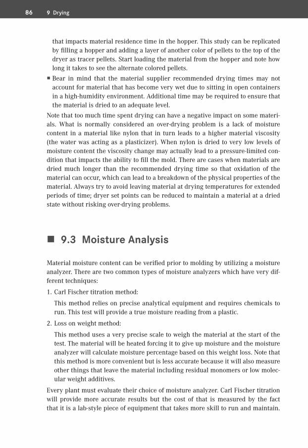
�� 9.3� Moisture Analysis
Material moisture content can be verified prior to molding by utilizing a moisture analyzer. There are two common types of moisture analyzers which have very dif-ferent techniques:
1. Carl Fischer titration method:
This method relies on precise analytical equipment and requires chemicals to run. This test will provide a true moisture reading from a plastic.
2. Loss on weight method:
This method uses a very precise scale to weigh the material at the start of the test. The material will be heated forcing it to give up moisture and the moisture analyzer will calculate moisture percentage based on this weight loss. Note that this method is more convenient but is less accurate because it will also measure other things that leave the material including residual monomers or low molec-ular weight additives.
Every plant must evaluate their choice of moisture analyzer. Carl Fischer titration will provide more accurate results but the cost of that is measured by the fact that it is a lab-style piece of equipment that takes more skill to run and maintain.
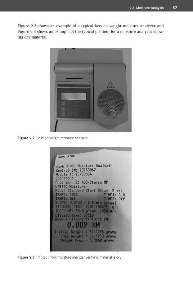
879.3 Moisture Analysis
Figure 9.2 shows an example of a typical loss on weight moisture analyzer and Figure 9.3 shows an example of the typical printout for a moisture analyzer show-ing dry material.
Figure 9.2 Loss on weight moisture analyzer
Figure 9.3 Printout from moisture analyzer verifying material is dry

9711.7 Orifice Size
3. Valve gates are used to direct the gate onto the part with minimal vestige and are also used to control the flow when using multiple valve gates. Because they can be shut off independently you can control flow fronts and knit line. When doing a color change with a valve gate the previous color may stick to the pin and continue to drag out. Cycling the valve open and closed can help with break-ing free of the previous material or color.
�� 11.5� Drooling, Stringing, and Sprue Sticking
Drooling from the hot drop tip or sprue is usually a result of a lack of cooling or lack of bearing surface. Tip designs over the years have incorporated insulator gaps and minimal contact with the tip to prevent freeze off and heat transfer to the cavity blocks. In many cases and with some materials this is a good thing. But with some materials an increased contact surface with the cavity steel along with cool-ing lines around the hot drop is necessary to prevent drooling, stringing, and sprues from sticking.
�� 11.6� Freeze Off
Freeze off in the tip area is usually caused by a lack of heat or the orifice size being too small. With some materials, especially semi-crystalline polymers such as nylon, temperature control at the tip is critical. This is when you want minimal contact surface with the tip and the cavity steel. Many hot runner suppliers use different tip designs to increase temperature control at the orifice. Low vestige tips have a pointed insert, typically called a spreader tip, that is designed to maintain temperature control at the orifice to prevent freeze off. The location of this spreader tip in relation to the orifice is critical and manufacturer specifications should be followed.
�� 11.7� Orifice Size
The orifice size will depend on the material, wall stock, and tip style being used. It is important to keep an open mind with orifice sizes when addressing issues with pressures, high gates, drooling, freeze off, and scrap.
98 11 Hot Runners
Selection of proper orifice size must be analyzed carefully to ensure a balance be-tween all factors. Computer-aided flow analysis can help with predictions of how well a given gate orifice will be at filling and packing a mold. Consult with material suppliers and hot runner manufacturers for recommendations on orifice sizes.
Case Study
This concerns a part having a scrap issue with splay where the orifice size ended up being the solution. This was a part with four low vestige tips that had a spreader tip in the center of the gate orifice. Many will just consider the orifice diameter and not include the area of the spreader tip that reduces the volume. In this case the orifice diameter was 0.050″ and the spreader tip in the center of the gate was 0.025″ diameter. The area of the spreader tip reduced the area/volume by 25%. The fill speeds with this gate needed to be on the high end to make a good part but we struggled with a lot of splay. We opened the orifice diameter to 0.060″, which was an in-crease of 55% in area/volume when considering the area that the spreader tip took away. This allowed us to adjust the fill speed and eliminate our splay/shear issue.
�� 11.8� Leakage
Hot runner leakage can be a major problem that will shut down a mold. A big development toward reducing hot runner leakage occurred when the hot drops started being threaded to the manifold versus relying on the stack height, seal rings, and bolt patterns in the mold plates to hold the hot runner together. Some toolmakers complained from a maintenance perspective that this was more diffi-cult to work on when the drops had to be removed for service. In some cases this was true with threads getting galled up and creating another mess. But improve-ments with thread designs and coatings have reduced this concern among tool-makers. So in the big picture of hot runner issues this has been a big improvement for maintaining molds.
Another observation over the years, but not a common one recently, is with sup-port in the hot half. If the areas cleared out for the hot runner are excessive, cavity pressure can lead to deflection within the mold plates leading to leakage.

9911.10 Hot Runner Troubleshooting
�� 11.9� Zones and Wiring
Hot runners have zones, typically identified with numbers, which are dependently controlled with a heater and a thermocouple. It is important to have the wires la-beled for each zone so it is easier to troubleshoot versus having to chase wires down, especially when multiple zones are used. A hot runner schematic should be on the side of the tool showing each zone, location, and the heater watts.
The power plug/connection and the thermocouple plug/connection are also iden-tified by zones. So, for example, the zone 1 heater leads would be to zone 1 on the power plug and the thermocouple to zone 1 on the thermocouple plug. The two wires coming off the heater are the same but on the thermocouple they are not. The thermocouple has a positive and negative wire that must be wired to the cor-rect location on the plug or it will not function properly. Similar to the battery in your car, it is not complicated but will not work if wired in reverse. Also, thermo-couples come in different types but the J type with the red and white wires is most common. The positive wire is magnetic, and is the white wire for the typical J type, and the red one is the negative. If you are ever in doubt which one is the positive wire you can use a magnet to find out. Make sure to use the proper thermocouple for the chosen hot runner controller. With thermocouples be cautious adding wire extensions unless you are experienced with proper methods and problems with cold junctions. With the heater and thermocouple any connections with extensions must be insulated.
�� 11.10� Hot Runner Troubleshooting
There are some things you can do in the molding machine to troubleshoot hot runners instead of pulling the mold for repair. A first thing to try when having hot runner issues is to change out the cables and controller. Long experience has shown that the controller or cables are often the source of the issue. Also, just be-cause the controller shows a zone at the proper set temperature does not necessar-ily mean that this is the case if you are having an issue. Also verify the pins in the plugs, because at times they can get pushed in not making contact with the con-nection on the cable plug.
Use a pyrometer with a 0.040″–0.060″ diameter sheath thermocouple to verify temperatures inside the hot drops or the inlet channel. With valve gates you pull the valve pin back to get inside the drop flow channel (note: always use proper safety precautions including face shields and move the injection unit away from the mold to avoid a blowout while probing tips). Make sure to contact the steel in

23�� 23.1� Description
Contamination is a broad term that covers visual defects that appear in a molded part. Contamination may show up as specks of discoloration, streaks, splay, delam-ination, etc. See Figure 23.1 for an example of material contamination.
Also known as: black specks, black/brown streaks, color swirls
Mistaken identity: splay
Figure 23.1 Material contamination
Contamination

210 23 Contamination
�� 23.2� Contamination Troubleshooting Chart
Table 23.1 shows the contamination troubleshooting chart.
Table 23.1 Contamination Troubleshooting Chart
Molding Process Mold Machine Materialpoor changeover hot runner hang up hang up areas improper storagehigh melt temperature high hot runner
temperatureanti-seize regrind
wear surfaces robot contamination incoming contamination lubricants mixed materials cleaning
�� 23.3� Contamination Troubleshooting
There are a wide variety of ways that material can become contaminated. It can be a major challenge to try to work through all the possible routes of contamination. Most of the time the best place to start is with the material being brought to the molding machine and work backward from there.
23.3.1� Contamination Troubleshooting Molding Process Issues
Contamination can be brought on by several process issues including:
� Poor changeover � High melt temperature
23.3.1.1� Molding Process: Poor ChangeoverWhen a molding machine is stopped and goes through a material or color change there are many opportunities for contamination to occur. The entire feed system and melt delivery system must be thoroughly cleaned out to ensure that there is no residue of the prior material. Some of the key areas to examine include:
� Drying hopper. The drying hopper has several hang up areas including along the door edge, in the hopper loader, around the dispersion cone, the sample/drain tube, and in the distribution box. When conducting a material change all of these areas must be cleaned of all remains of the previous material. Hoppers can be

21123.3 Contamination Troubleshooting
vacuumed out to help with clean out. Watch out for areas such as the sample tube because this is a spot that is often forgotten.
� Feed lines. Whether feeding the machine from the drying hopper, gaylord, or bag, it is critical to ensure that all of the material has been cleaned out. This is usually as simple as removing the feed line and allowing the vacuum loader to suck all of the material out of the feed lines. There have been cases were the material handler does a nice job of cleaning everything out but forgot the feed lines and when the new material was introduced all of the previous material was pulled in with it, contaminating the material.
� Machine hopper. The machine hopper will have a variety of locations where ma-terial can collect. Make sure to remove the magnet and clean out around the magnet drawer (see Figure 23.2). The hopper should be completely cleaned of all residue from the previous material. Also be sure to watch for any mismatch ledges between components such as the feed throat and hopper.
� Loaders. Loaders can also be a location that will trap material pellets. All loaders must be cleaned as part of the material changeover process.
� Additive feeder bins. Additive feeder bins must be cleaned when swapping colors. The feed screw on a volumetric feeder must also be removed and cleaned to avoid contamination.
Figure 23.2 Pellets stuck in magnet drawer

212 23 Contamination
Often times molding shops will provide very little training for material handlers. If a material handler does not understand the importance of thorough cleaning during material changes they may cut corners which will lead to contamination. Provide a formal training for everyone in the shop that is responsible for loading materials to ensure that changeovers are executed correctly.
23.3.1.2� Molding Process: High Melt TemperatureWhen plastics are overheated they can degrade and contaminate the material with black specks or streaks. See Chapter 15 on black specks for more information about this problem.
23.3.2� Contamination Troubleshooting Mold Issues
Mold-related concerns that can cause contamination include:
� Hot runner hang up � High hot runner temperatures � Wear surfaces � Lubricants � Cleaning
23.3.2.1� Mold: Hot Runner Hang UpAny areas in a hot runner system that can trap material can lead to contamination. Material trapped in hang up areas can continue to bleed into the melt stream long after the material change has been completed. When dealing with materials that are more temperature sensitive the trapped material may degrade and contami-nate the parts with charred black specks. Figure 23.3 shows contamination from a hot drop tip.
Hot runner assemblies should be built in a way that at running temperatures there will be neither ledges nor mismatch locations that would hang up material. Drops must be securely assembled to the manifold so as to not leave any gaps between the drop and the manifold body.
Corners in hot runner manifolds can easily lead to dead spots where material hangs up. Depending on the hot runner design some manifolds will have corners that are gun drilled at 90° intersections. With a 90° intersection the outside of the corner will end up as a dead spot and material will be trapped in this location. Bet-ter designs have machined corner plugs with a curved corner, no dead spots.

21323.3 Contamination Troubleshooting
Figure 23.3 Contamination at hot tip
A manifold can be damaged and cracked which will provide a gap at the crack that will allow material to become trapped. Cracking a manifold is usually a result of a cold start where the manifold was not given enough time to heat soak. Cracked manifolds often need expensive and time-consuming repairs; therefore, educate process technicians to give a hot runner plenty of soak time before injecting plastic through the manifold.
23.3.2.2� Mold: High Hot Runner TemperaturesWhen hot runners are running at higher temperatures than is required for a mate-rial the odds of degrading material increase. As the material degrades in the hot runner system the result can be brown streaks or black specks contaminating the part.
Verify that the hot runner temperatures are set correctly and that actual tempera-tures are reading accurately. If a hot runner zone is constantly calling for heat it may indicate that a zone is either wired incorrectly or has a thermocouple mis-placed.
23.3.2.3� Mold: Wear SurfacesAny surfaces on a mold that rub against another surface have the opportunity to wear. Over time the metal dust or flakes that are worn from the surface can con-taminate the cavity of the mold. This metallic dust will contaminate the molded part and may produce a visual defect.
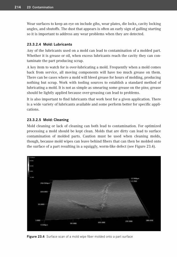
214 23 Contamination
Wear surfaces to keep an eye on include gibs, wear plates, die locks, cavity locking angles, and shutoffs. The dust that appears is often an early sign of galling starting so it is important to address any wear problems when they are detected.
23.3.2.4� Mold: LubricantsAny of the lubricants used on a mold can lead to contamination of a molded part. Whether it is grease or oil, when excess lubricants reach the cavity they can con-taminate the part producing scrap.
A key item to watch for is over-lubricating a mold. Frequently when a mold comes back from service, all moving components will have too much grease on them. There can be cases where a mold will bleed grease for hours of molding, producing nothing but scrap. Work with tooling sources to establish a standard method of lubricating a mold. It is not as simple as smearing some grease on the pins; grease should be lightly applied because over-greasing can lead to problems.
It is also important to find lubricants that work best for a given application. There is a wide variety of lubricants available and some perform better for specific appli-cations.
23.3.2.5� Mold: CleaningMold cleaning or lack of cleaning can both lead to contamination. For optimized processing a mold should be kept clean. Molds that are dirty can lead to surface contamination of molded parts. Caution must be used when cleaning molds, though, because mold wipes can leave behind fibers that can then be molded onto the surface of a part resulting in a squiggly, worm-like defect (see Figure 23.4).
Figure 23.4 Surface scan of a mold wipe fiber molded onto a part surface

21523.3 Contamination Troubleshooting
When wiping a mold surface, use clean lint-free wipes to minimize the opportunity for contaminating the mold surface. A dirty wipe not only leaves behind contami-nants but may also scratch the mold surface.
Be aware that there are cases where the grease in the mold breaks down due to chemical contact. This can be magnified if someone sprays mold cleaner directly on the ejector half of the mold. The cleaner solvents can impact the viscosity of the grease leading to contamination of the molded part from the broken-down grease.
23.3.3� Contamination Troubleshooting Machine Issues
Some of the machine factors that can lead to contamination include:
� Hang up areas � Anti-seize � Robot contamination
23.3.3.1� Machine: Hang Up AreasAny areas in the melt delivery system that have a mismatch can cause material to hang up. Some of the key areas that should be evaluated for hang ups include:
� Hopper to feed throat � End cap to barrel � Nozzle adapter to end cap � Nozzle to nozzle adapter � Nozzle tip to nozzle � Nozzle tip to sprue bushing � Damaged spots on screw, barrel, non-return valve, and end cap
It is a time-consuming process to disassemble these components and inspect for hang up areas but sometimes it is necessary to get to the root cause. Prior to shut-ting down for disassembly run another color of material through the barrel. This alternate color can help highlight spots where the original color is being trapped. Also look for areas of charred material when conducting this inspection. Again, this is a time-consuming process so make sure other potential causes are investi-gated first.
Examination of nozzle tips of different style will show locations where material can become trapped. See Figure 23.5 for cross sections of common nozzle tips: notice the potential dead spot at the ball end of the general-purpose style tip. General-pur-pose tips can cause contamination and streaking issues due to this dead spot.
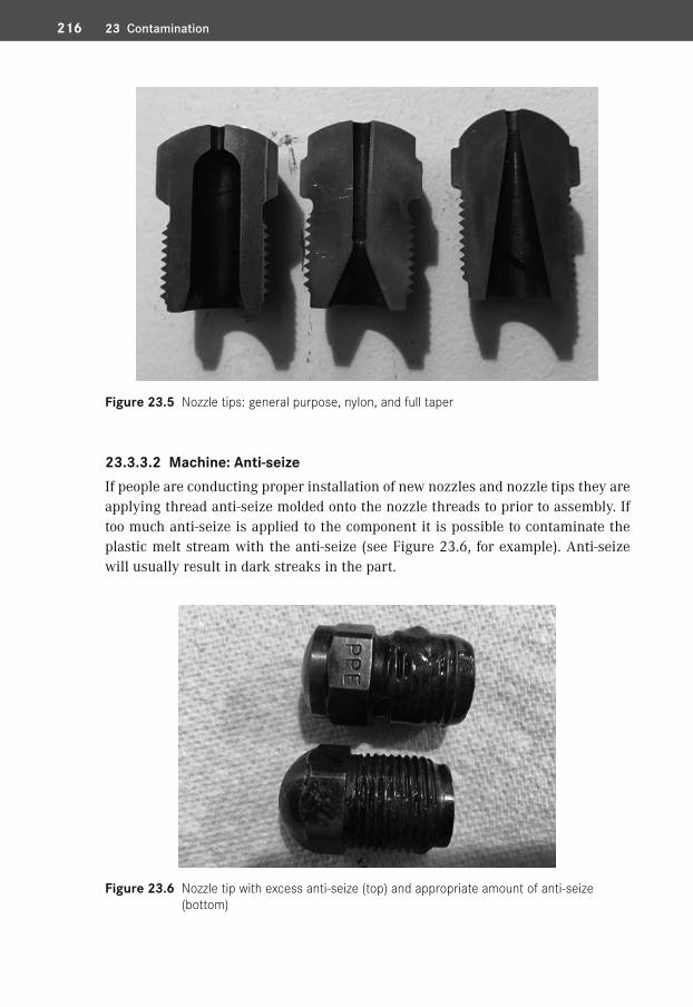
216 23 Contamination
Figure 23.5 Nozzle tips: general purpose, nylon, and full taper
23.3.3.2� Machine: Anti-seizeIf people are conducting proper installation of new nozzles and nozzle tips they are applying thread anti-seize molded onto the nozzle threads to prior to assembly. If too much anti-seize is applied to the component it is possible to contaminate the plastic melt stream with the anti-seize (see Figure 23.6, for example). Anti-seize will usually result in dark streaks in the part.
Figure 23.6 Nozzle tip with excess anti-seize (top) and appropriate amount of anti-seize ( bottom)
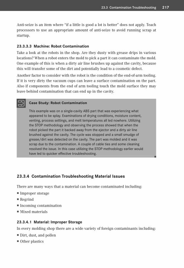
21723.3 Contamination Troubleshooting
Anti-seize is an item where “if a little is good a lot is better” does not apply. Teach processors to use an appropriate amount of anti-seize to avoid running scrap at startup.
23.3.3.3� Machine: Robot ContaminationTake a look at the robots in the shop. Are they dusty with grease drips in various locations? When a robot enters the mold to pick a part it can contaminate the mold. One example of this is when a dirty air line brushes up against the cavity, because this will transfer some of the dirt and potentially lead to a cosmetic defect.
Another factor to consider with the robot is the condition of the end-of-arm tooling. If it is very dirty the vacuum cups can leave a surface contamination on the part. Also if components from the end of arm tooling touch the mold surface they may leave behind contamination that can end up in the cavity.
Case Study: Robot Contamination
This example was on a single-cavity ABS part that was experiencing what appeared to be splay. Examinations of drying conditions, moisture content, venting, process settings, and melt temperatures all led nowhere. Utilizing the STOP methodology and observing the process showed that when the robot picked the part it backed away from the ejector and a dirty air line brushed against the cavity. The cycle was stopped and a small smudge of grease/dirt was detected on the cavity. The part was molded and it was scrap due to the contamination. A couple of cable ties and some cleaning resolved the issue. In this case utilizing the STOP methodology earlier would have led to quicker effective troubleshooting.
23.3.4� Contamination Troubleshooting Material Issues
There are many ways that a material can become contaminated including:
� Improper storage � Regrind � Incoming contamination � Mixed materials
23.3.4.1� Material: Improper StorageIn every molding shop there are a wide variety of foreign contaminants including:
� Dirt, dust, and pollen � Other plastics

33�� 33.1� Description
Variations in gloss on a part will lead to cosmetically unacceptable parts. If the part has areas that are glossy and areas that are dull the variation in appearance can be very unattractive. Figure 33.1 shows an example of gloss variation.
Also known as: spotty, glossy, dull
Mistaken identities: sink, scuff
Figure 33.1 Gloss variation
Gloss Variation

320 33 Gloss Variation
�� 33.2� Gloss Variation Troubleshooting Chart
Table 33.1 shows the gloss variation troubleshooting chart.
Table 33.1 Gloss Variation Troubleshooting Chart
Molding Process Mold Machine Materialsecond-stage pressure mold surface finish machine performance material typesecond-stage time cooling additivesfill velocity venting fill only weight inconsistent wall stock mold temperature melt temperature
�� 33.3� Gloss Variation Troubleshooting
Gloss is determined by the nature of the surface of the mold, i. e. polished or grained, and how well the plastic replicates the mold surface. The first step of trou-bleshooting gloss problems is to establish if the mold surface is being replicated. As an example, if a mold surface is a sand-blast finish the part will be dull no mat-ter what the process is (see Chapter 6 for more on mold finish).
Another item to keep in mind when reviewing gloss callouts is that parts that are on the two ends of the gloss spectrum will tend to show scratch and mar defects easier than parts with a more mid-range of gloss. Sometimes the difference be-tween a 2.5 and 3.5 gloss reading can make a major difference in the appearance of the part and the ability of the part to look good after handling. Extremely low gloss levels such as a 2.5 can make it very challenging to get a good-looking part.
It is important to understand that in many cases gloss problems are actually truly a read-through (difference in gloss due to differential pack and shrink at wall stock transitions).
33.3.1� Gloss Variation Troubleshooting Molding Process Issues
Common molding process related problems include:
� Second-stage pressure � Second-stage time

32133.3 Gloss Variation Troubleshooting
� Fill velocity � Fill only weight � Mold temperature � Melt temperature
33.3.1.1� Molding Process: Second-Stage PressureThe most important process setting for gloss on molded parts is the pressure ap-plied to the plastic in the cavity. If not enough pressure is applied to the plastic the molded part will not replicate the finish of the mold well. This applies for polished surfaces, textures, and sand-blasted finishes. Think about the surface of the molded part compared to the mold surface: is the plastic being packed into all of the micro-scopic surface detail of the surface of the mold?
Examining mold surfaces under magnification will show a series of polish scratches on polished surfaces and a series of peaks and valleys on a textured part. To have adequate replication of these microscopic surface details the plastic has to be pres-surized at the appropriate levels. If the pressure is not high enough, the surface will not reflect the details of the mold surface.
Variation in pressure across a mold will result in a potential variation in gloss levels across the part. Low-pressure areas will not replicate the surface as well, and will typically have a different gloss appearance when compared to better-pres-surized areas. This can often manifest as a distinct difference between areas near and farthest from the gate. Also watch for areas that fill quickly and freeze before being packed out.
One of the challenges faced in injection molding is trying to minimize the pressure drop across the mold cavity. Some of the keys to minimizing pressure drop include filling fast to avoid viscosity variations during first-stage injection. Proper gate placement is also critical to ensuring a minimized pressure drop. To determine gate quantity and location a flow analysis software such as Moldflow® is a valuable first step before steel is cut.
When troubleshooting for gloss problems check that the second-stage pressure is set at the correct value (do not forget to account for intensification ratio). Also check to see if the correct nozzle and nozzle tip are being used because a mixing nozzle will result in a large pressure drop between the machine and the end of the cavity.
Cavity pressure transducers will provide very useful data on the actual pressure within the mold. If a transducer is located near the gate and at the end of fill loca-tion, accurate data on what is occurring in the cavity will be easy to obtain.

322 33 Gloss Variation
33.3.1.2� Molding Process: Second-Stage TimeSecond-stage time that is not long enough to ensure gate seal can lead to a glossy area near the gate. If the plastic is not retained in the cavity until gate seal there will be a depressurization of the plastic near the gate. The release of plastic near the gate will create a localized low-pressure area that will typically have a different gloss level than the rest of the part.
Verify that the second-stage time is set correctly per the documented process. A gate seal study should be conducted during process development to determine the appropriate second-stage time. If a gate seal study was not conducted take the time to complete a gate seal study to understand the correct time required for establish-ing gate seal.
33.3.1.3� Molding Process: Fill VelocityGenerally, a faster fill velocity will provide less pressure drop and yield better sur-face replication. Faster fill rates tend to provide a glossier surface whereas surfaces obtained with slow fill rates tend to be duller. Faster fill velocities also lead to a part that will pack out more uniformly.
Verify that the fill time is correct according to the documented process. Fill velocity settings may not match, but fill time should. If fill time and fill only weight repli-cate the desired process that ensures that the same volumetric flow rate occurred.
33.3.1.4� Molding Process: Fill Only WeightIf the fill only (95–98%) shot is too light due to an early transfer there may be a gloss difference that forms in a sharp line where transfer occurred. An early trans-fer can create a very distinct area at end of fill that looks different.
Check the fill only weight to ensure that the part is filled to 95–98% during first stage. If the shot is short the transfer position should be adjusted to provide an adequate fill shot. Be aware that filling too short can lead to a lag in second-stage pressurization. Figure 33.2 shows process monitoring data on a process with an early transfer. Note how the screw travel curve moves significantly after transfer. As the screw continues to move forward the machine is trying to reach the set sec-ond-stage pressure but it takes several seconds. Early transfer creates many issues but gloss variation is an often-overlooked problem.

32333.3 Gloss Variation Troubleshooting
Figure 33.2 Process monitoring curves showing an early transfer
33.3.1.5� Molding Process: Mold TemperatureA low mold temperature can tend to produce a lower gloss level whereas a higher mold temperature can produce a higher gloss level. However, this is another factor that impacts how well the plastic replicates the mold surface, and hotter mold sur-faces lead to better replication of the mold surface.
In recent years rapid mold heating and cooling systems have been used to improve the replication of the mold surface. The extra heat that is applied to the mold sur-face allows the plastic to pack out against the steel much better. Use of rapid mold heating and cooling can yield very high-gloss surfaces when molded on a polished surface. If the mold has a micro texture the replicated surface can be very low in gloss.
There are times when high mold temperatures lead to a rippled surface that will show variation in gloss. The heat of the mold creates an effect where the wall is collapsing away from the mold surface that is sometimes referred to as “heat sink”. Reducing the mold temperature or adding second-stage pressure will often resolve this defect.
33.3.1.6� Molding Process: Melt TemperatureWhen molding with a low melt temperature the pressure drop across the mold will be increased. With the increase in pressure drop many times a variation in gloss will occur. If the mold is not pressurized at a uniform level there is likely going to be variation in gloss levels.
324 33 Gloss Variation
Verify that the melt temperature matches the documented process. If the melt tem-perature is wrong then evaluate the following:
� Barrel temperatures set point versus actual � Back pressure � Screw recovery rate
33.3.2� Gloss Variation Troubleshooting Mold Issues
One of the biggest impacts on gloss levels of a molded part is the mold itself. The main factors that impact the gloss level are:
� Mold surface finish/texture � Cooling � Venting � Inconsistent wall stock
33.3.2.1� Mold: Surface Finish/TextureOne of the biggest contributors to the gloss of a molded part is the mold surface finish. A sand-blasted mold surface will not produce a high-gloss piano black gloss level no matter what is done to the process.
There is a wide range of finishes that can be used for an injection mold. They in-clude:
� Polish � Texture � Sand/glass blast
All three of the above options also have many different levels that can impact the part appearance. For example, a polished surface can be polished to a variety of gloss finishes.
If nonuniform gloss is a problem on a part, the surface of the mold should be in-spected for areas of variation on the surface. To effectively do this a strong light is often needed to avoid shadows on the surface. Many times upon inspecting the mold surface, areas of worn texture or buildup will be visible. Sometimes a thor-ough cleaning of the mold surface will eliminate the variation and other times the mold will need to be sand blasted. Inspecting the mold surface can eliminate a lot of troubleshooting time because if the gloss problem is on the mold surface, pro-cessing will not resolve it. Buildup can also be an issue on polished surfaces (see Figure 33.3).

32533.3 Gloss Variation Troubleshooting
Figure 33.3 Mold surface buildup (right) versus clean surface (left)
Case Study: Polish Buildup
In this case the material being molded was a wood-filled polypropylene. The mold had a polish level of approximately SPI A3, which produced nice glossy black parts when molded with straight polypropylene. An extended run was conducted for a special order of wood-filled polypropylene parts that mold-ed well; however, when the material was changed over to the black poly-propylene the gloss level of the parts was dull and inconsistent. Examination of the mold surface showed there was a large amount of buildup on the mold surface and the steel had even tarnished from the gases from the wood-filled material. After many hours of scrubbing with polishing paste, the mold was finally ready for running at high gloss.
Often when a mold texture is used there will either be a secondary micro texture or a sand-blasted finish that creates additional small details that the plastic must be packed into. Under magnification these peaks and valleys will be easy to see and examine for detail. In Figure 33.4 texture details can be viewed under 200× magni-fication: notice the peaks and valleys that the material must replicate.

Symbols4M 44M Basic 8 7, 301, 3834M method 18, 324M troubleshooting 148, 4665 Why 5, 13
Aabrasive 441ABS 37, 81, 144, 149, 179, 217, 219, 237, 328,
415, 436, 479acetal 155, 171, 189, 221, 235, 247, 272,
395acid flush 130, 404acrylic 328actuated vent pins 59additive feeder bins 211additives 81, 190, 296, 328, 416agglomerates 220airflow 85air poppets 341, 425alarms 383alloys 280aluminum oxide 48, 49amorphous 251, 252, 266, 344, 468analog input 123anisotropic 468, 470anisotropic shrink 253anti-seize 160, 216ASA 328aspect ratio 480
Bbackfill 58, 381backfilled 301, 302
back pressure 76, 156, 167, 175, 183, 201, 203, 229, 266, 311, 324, 383, 403, 415, 417, 419, 454, 474
baffle 404, 405ball-style non-return valve 250barrel 135barrel heaters 137barrel shot capacity 258barrel temperatures 153, 167, 183, 188, 266,
311, 403, 454, 474bead blasted 442bearing surface 55, 97, 447Beaumont Effect 104Beaumont Inc. 104Beaumont, John 104bimetallic carbide barrels 391black/brown streaking 91, 209black or brown specks 131black specks 91, 186, 209blades 259blast media 47blend 303, 326blisters 165, 236, 451blowing agent 412, 427, 429blush 141bore 42bosses 340, 347Bozzelli, John 29, 61, 85brainstorming 15brass tools 340breakaway distance 262breakaway speeds 339breaking 223brittle 225brown streaking 137, 151, 181, 186bubblers 128, 259, 366, 405bubbles 81, 165, 296, 451buildup 130, 173, 186, 194, 324, 341, 350, 387
Index

482 Index
burning 120, 311, 402burns 53, 101, 181, 258burrs 228, 340, 350byproducts 186
CCAD model 303CAE 269CAE flow analysis 463CAE software 459calibration 75, 273capacity issues 255caprolactam 179carbon 220carbon buildup 131, 135Carl Fischer titration 86, 416cashew gate 34, 108, 148, 235, 277, 279, 359,
408cavity 242, 340cavity balance 30, 31, 101, 116, 360, 385, 395,
407cavity cooling 103cavity fill balance 107cavity fill rates 103cavity fill time 115cavity imbalance 33, 466cavity instrumentation 111cavity locking angles 214cavity pressure 59, 103, 243, 258, 267, 282,
290, 292, 338, 453, 462, 473cavity pressure curve 361, 408cavity pressure transducers 111, 241, 321,
347, 399cell packed 373cellulosic 81change log 17changeover 189, 193, 196, 210changeovers 200charred 183, 190check valves 64chicken scratches 299chiller 403chute 226, 372clamp force 106, 282, 285clamp open 263clamp parallelism 293clamp pressure 282clamp tonnage 285clamp velocities 262cleaning 324
cleanout 231cloudiness 91, 191cold slugs 277, 436cold slug well 147, 269, 423cold starts 213, 389colorant 179, 307, 442colorant concentrate 161color changes 96, 194color concentrate 163, 190, 201, 204, 231,
237, 238color mixing 203, 271, 419color streaking 91, 199color swirls 181, 199, 209component deflection 247compression ratio 161, 171, 187, 426computer-aided flow analysis 98computer flow analysis 304, 477computer flow simulation 456condensation 420containers 196contaminants 138, 162, 185contamination 91, 157, 172, 191, 196, 202, 206,
222, 231, 233, 237, 391, 395, 427conveyor 226, 263, 371, 372cooling 103, 106, 125, 246, 256, 257, 326,
351, 366, 454, 455, 460, 466cooling capacity 403cooling circuits 404cooling rate 115, 326, 458, 459cooling time 242, 244, 256, 258, 260, 261,
348, 358, 434, 464cooling tower 403copper alloys 366, 438copper-based alloys 128, 405core 226, 259, 294core circuit 294cored out 367core half 226core pin 261, 406, 476core pressure 290core pull cylinders 290core pulls 44cores 128, 340coring 455cost 255cover half 225cover side detail 338crack 169, 170, 194, 424cracking 223crazing 227crystallinity 246

483Index
cushion 64, 157, 245, 249, 383, 401cushion monitoring 383, 388cycle time 125, 201, 226, 244, 246, 255, 295,
419, 421, 439cylinder bore gauge 392cylinders 41cylinder size 290
Ddamage 215, 340, 350decompression 168, 184, 245, 415, 418, 445Decoupled II® 32Decoupled III® processing 122Decoupled® II molding process 258Decoupled®/scientific molding 29, 30, 243deep draw 261deep rib 340deflection 282, 364deformation 358degating 277degradation 151, 167, 225, 338, 417, 426degrade 183, 190, 212, 229, 441degraded 91, 131, 201, 387delamination 91, 209, 231, 233, 414depression 397desiccant 82–84, 416desiccant beds 84design 145, 227, 297, 303, 307, 313, 349, 351,
367, 398, 406, 452, 455, 458, 472, 477Design of Experiments 16dew point 82, 83, 416, 442dew point meter 83dew point monitors 23D-gate 35dial indicator 285diamond 194diamond chrome 177diamond polish 51die blue 366die height 285die locks 214dieseling 181differential cavity pressures 364differential cooling 247differential shrink 261, 364, 366, 458dimensional issues 72, 101, 247dimensions 239, 242, 283dings 369direct gating 95discoloration 151
dispersion tip 272distort 338distortion 347, 357, 457donuts 374downtime 186, 343draft 44, 261, 340, 359, 373draft analysis 340draft angles 228, 340, 349, 352drag 359, 373drags 228draw polish 51, 341, 349, 359, 374, 435, 436drool 168, 184, 418, 445, 450drooling 97drop 212dryer monitoring 123drying 81, 415drying hopper 210dull 141, 309, 319durometer 342duty cycle 273dynamic check valve study 64
E
eDART® 400, 409EDM 228, 349, 387, 408ejected 258ejection 225, 226, 261, 279, 464ejection force 359ejection speed 348ejection stroke 261, 350, 372ejection surface area 349, 359ejection temperature 455, 464ejector area 374ejector box 289ejector pins 112, 230, 279, 365ejector plate 263, 289, 351, 360, 365ejector plate stop buttons 365ejector side 342, 356ejector speed 357end cap 135, 187, 215, 236end of arm tooling 217, 370end of fill 183, 302, 310end of fill cavity pressure 271end-of-fill transducer 114environment 253environmental stress cracking 227, 459erosion 185, 288, 290, 350, 440, 441

484 Index
F
family molds 109, 292feed lines 211, 237, 264feed throat 170, 215, 264, 404, 415, 420, 426fiber orientation 478filled material 251, 252fillers 81, 307, 362, 469, 478fill only 63, 143, 310fill only shot 29, 243, 250, 284fill only weight 30, 72, 267, 301, 322, 379,
400, 410fill pressure 246fill time 258, 267, 306, 310, 381, 402fill velocity 142, 183, 242, 258, 265, 266, 300,
310, 322, 333, 473filters 85fines 139first stage 243first-stage fill 284first-stage injection velocity 381first-stage velocity 402fishbone diagram 4, 14flaking 277, 424flame-retardant 328flame retardants 179flash 54, 72, 101, 258, 279, 281, 297flow 259flow analysis 303flow analysis software 246, 321flow defects 307flow distance 246flow front 302, 303, 333, 475, 478flow front velocity 312flow leader 303flow length 103, 253, 268, 292, 302, 313,
380, 467flow lines 141, 299, 414flow marks 141flow meter 27, 123, 402flow pattern 303flow rates 327, 454foreign material 220, 249, 269, 386fountain flow 34, 473fracture 223freeze 245frozen layer 384, 467frozen layer plot 246, 456full taper tip 270
Ggalling 214gallons per minute 402gas assist 293, 425gas assist control 122gas assist injection molding 411gas booster 411gas counter pressure 429gas traps 165, 181, 184, 451gate 141, 152, 260, 267, 303, 313, 477gate design 108gate flaking 420gate freeze 268gate land 34, 268gate land length 146, 334gate location 268, 334gates 253, 279, 386, 395, 406, 467gate seal 30, 33, 38, 114, 146, 147, 227, 241,
256, 322, 399, 400, 463gate seal study 29, 322, 453gate seal time 433, 455gate size 142, 245, 334, 407gate spacing 246gate style 380gate thickness 145gate vestige 34gating 33, 257, 313gating thin to thick 458gaylord 218gaylord tipper 394gel tape analysis 220general-purpose screw 202, 203gibs 214glass 252glass bead 48glass content 316glass fibers 309, 310glass-filled 33, 34, 39, 50, 59, 128, 249, 259,
307, 309, 311, 328, 391, 436, 440–442glass-filled materials 168glass transition temperature 348glassy 309, 310glassy surface 315gloss 47, 53, 101, 142, 319, 363gloss variation 72, 309, 328glossy 319, 355grained 320grease 157, 185, 214grinder 139grinding 163

485Index
gripper fingers 352grippers 352, 371Groleau, Rod 29, 61, 111guided ejection 374gusset ribs 439
Hhalo 141handling 227, 369hang up 96, 135, 152, 189, 194, 195, 204, 210,
215, 226, 235, 236hang up areas 160, 212, 215heat deflection temperature 459heater 95, 99heater band 159, 184, 448heater band burnout 159heat exchanger 404heat sink 323heel block 290hesitation 299, 302, 476hesitation lines 300high fill pressure 265high-gate 35high-gloss 328high melt temperature 132, 225high pressure 268high temperature 174hob 290hold volume 399, 409, 410hopper 222, 237, 394hopper loader 210horn pins 44, 290hot drops 34, 40, 387, 446hot drop tips 96, 423hot oil 312hot runner 93, 95, 146, 169, 189, 194, 212,
226, 235, 246, 261, 268, 303, 383, 422, 446
hot runner cables 388hot runner controller 120, 247hot runner leakage 98hot runner manifold 120, 289, 401, 422hot runner plugs 154, 388hot runner system 153, 202hot runner temperatures 134, 313, 388, 405,
420hot runner tip 146hot sprue 438hot tip 91, 386, 443, 448hydraulic 186
hydraulic cylinders 236, 350hydraulic gauge 294hydraulic leaks 293hydraulic pressure 294hydraulic pressure gauge 76hydraulic response 74hydraulics 41hydraulic system 306hydrolysis 90, 230, 274, 296, 315, 441hygroscopic 89, 171, 189, 197, 416, 441, 480
Iimbalance 101impact modifiers 81, 232impinge 334infrared (IR) 77injection compression 60injection fill velocity 175inserts 128, 405insulator 445, 448, 449, 455insulator caps 96insulator gaps 97, 158intensification ratio 167, 203, 338, 382,
475IR temperature gun 201IR thermal imaging 137is/is not 17ISO pipes 128
Jjetting 34, 141, 192, 331
KKistler Group 112knit lines 184, 312, 471knock-out bars 263, 351, 360
LL*a*b* 207label 206, 222, 237labeling 196laminar flow 104, 126land length 145larger tonnage machine 283laser welding 288L/D 187L/D ratio 426

486 Index
leader pin 372leakage 250leaking 236, 245, 383leaking hot runner manifolds 389letdown ratio 204, 412, 307lifter 185, 229, 247, 277, 279, 348, 350, 374lifter pocket 366lifter read 363lifter rods 365linear thermal expansion 253line of draw 290, 340loaders 211, 420loading of pack 373load sensitivity 63lock angle 41locking angle 290lockout/tagout 21lockup 288, 295long flow lengths 257long glass fibers 311long glass-filled 394loop 299loss on weight 86, 416low back pressure 168low-gloss 328low-vestige-style hot tip 268low vestige tip 96, 386lubricant 214, 236lubricants 179, 264, 353, 361, 421, 424
Mmachine controllers 75machine hopper 211machine shutdown 132machine testing 61machining/cutter marks 358machining marks 349magnets 220, 272maintenance 70manifold 212marbling 199marring 374masterbatch 179, 412, 442material change 186, 193, 212material contamination 131material feed 243, 394, 415material leaking 401mechanical switches 45meld lines 300, 303, 312, 471melt consistency 269
MeltFlipper® 104melt flow index 232, 296melt front 266melt index 480melt probe 201, 311melt stream 167melt temperature 123, 144, 167, 174, 183, 192,
201, 225, 234, 243, 256, 264, 266, 286, 301, 311, 323, 338, 348, 357, 384, 403, 415, 445, 454, 462, 473
metal 269metal inserts 220metallic flaked 479metallic flakes 307metal shavings 404microcellular foam 429microetching 48micro texture 323, 325milkiness 191mineral 252, 328mineral deposits 404minimum mold size 295mismatch 135, 160, 169, 187, 194, 195, 212,
215, 235, 236, 291miter locks 134mixing 201mixing elements 161mixing nozzles 202, 270, 391mixing screw 161, 203mixing style screws 202mixing tips 148, 202moisture 81, 86, 171, 178, 189, 197, 415, 450moisture analyzer 23, 86, 343, 416moisture content 230, 274, 306, 315, 343,
441mold breakaway speeds 227mold cleaner 157, 215mold cleaning 185, 214mold component deflection 364, 365mold cooling 244mold deflection 25, 285, 289mold design 169, 253, 257, 327, 334, 349,
350, 365, 366Moldflow® 321, 333mold inserts 157mold open speed 339mold release 344mold steel temperature 128mold surface 320mold surface finish 324mold surface temperatures 302

487Index
mold temperature 119, 120, 144, 193, 244, 246, 256, 311, 323, 347, 357, 365, 384, 402, 453, 459, 475
mold temperature control unit 122molecular weight 90, 232, 274, 296, 307, 343MuCell® 293multicavity 101, 292, 341, 385multimeter 22multiple ejector strokes 263
Nnippers 371nitrogen 411nominal wall 452, 455, 458, 475nominal wall stock 257, 261, 340, 367, 406,
477non-return valve 64, 245, 249, 379, 383, 389,
401, 410, 426nonuniform 201nonuniform wall stock 257nozzle 135, 148, 187, 215, 236, 390, 439, 448nozzle adapter 215nozzle drool 435nozzle leak 392nozzle lengths 271nozzle orifice 236nozzle temperature 144, 444nozzle tip 169, 215, 248, 269, 383, 390, 401,
410, 418, 420, 423, 439, 443, 449nozzle tip orifice 135, 391nucleated 197, 412nucleating agents 252, 264, 469nucleation 362, 442nylon 39, 86, 87, 89, 97, 171, 179, 180, 231,
272, 275, 288, 306, 315, 394, 415, 441nylon 6 312, 317nylon tip 270
O
oil 185, 214opaque 197, 456operator 372orientation 458, 469, 470, 479orifice 97, 98orifice gauge 148outgassing 53, 190overflow 59, 312, 411, 479overflows 122overheated 201
overheating 78, 96, 187over-packed 347over-packing 338
P
pack 283packaging 372, 469packed 242pack rate 115part design 224, 261, 340, 359, 367, 374, 398part design issues 257part detail 359part ejection temperature 128, 365, 366parting line 280, 282, 286, 287, 340, 374,
383, 444, 466parting line bearing surface 425parting line flash 185part out temperature 258, 357, 385path of least resistance 381Paulson, Don 29PC/ABS 34, 81, 144, 149, 161, 203, 221, 235,
274, 415, 466peak injection pressure 379peak pressure 274perimeter venting 425perpendicular 381piano black 324pigments 207pin deflection 349pin marks 355pin push 72, 261, 355, 359pin read 363pins 277plastication 175, 177, 264, 274plasticizers 190plastic pressure 203platen 289, 293platen deflection 106, 289platen parallelism 106platen wrap 295plate out 173, 385plugged 269, 404PMMA 171poka-yoke 237polish 194, 320, 321, 324polished 50, 228polishing 47, 288polycarbonate 81, 133, 149, 171, 179, 328, 343,
352, 415, 423, 441, 451

488 Index
polyester 315, 343, 352polyesters 81, 171, 230, 415, 441polyethylene 155, 237polypropylene 38, 90, 132, 146, 155, 193, 197,
207, 237, 272, 341, 359, 366, 373, 425, 436, 462, 465, 429
polystyrene 196poppet valve 402porous steel 58post-gate cavity pressure 400post-gate transducer 114post-mold handling 464post-molding 224post-mold shrinkage 243, 244PP 35, 204, 205PPO 179preload 290preloaded push pins 342pressure 76pressure differential 243pressure drop 103, 115, 146, 202, 246, 266,
270, 321, 379, 403, 453, 462pressure-drop study 38, 39pressure gauge 273pressure limited 29, 38, 39, 86, 203, 265,
266, 306, 310, 379pressure limiting 66pressure loss 34, 96pressure profile 399pressure relief valve 43, 294pressure response 286pressure-sensitive film 440preventative maintenance 427Priamus System Technologies 112process control 122, 426process monitoring 23, 71, 117process monitoring curves 379process monitoring system 76process window 225profile 235profiled first-stage fill velocity 333projected area 283, 292proximity switches 45pullers 358pull sink 408purge 91, 132, 342purging 163, 168, 186, 200purging compound 92, 196PVC 132, 155, 171, 189, 190, 221, 235, 441pyrometer 22, 99, 106, 120, 365, 460
Rradius 224, 228, 406rapid mold heating 475rapid mold heating and cooling 323read-through 261, 320, 326, 363, 365, 366record grooves 299, 300recording 299recovery speeds 156regeneration heaters 84regrind 95, 138, 163, 177, 196, 219, 231, 264,
271, 297, 307, 394, 450release 339release agents 179, 190, 232, 264, 344, 353,
361, 442relief 54residence time 132, 155, 187, 189, 207, 225,
235, 415, 419, 474resin remover 342restriction 271return air 84reverse-flow thermolator 169, 424Reynolds number 126ribs 347, 381rib to wall 398rib to wall ratio 458ring gate 37ring vent 421rippled surface 323RJG Decoupled III® process 394RJG Decoupled Molding® 284, 379, 400RJG Decoupled® process 382RJG eDART® 23, 74, 84, 113, 203, 243, 273,
286, 410RJG Technologies 111, 122robot 78, 217, 226, 263, 352, 370, 465, 468root cause 1rubber gels 220rubber modifiers 328ruby stone 374runner 242, 246, 260, 268, 297, 313runner length 380
Ssand-blasted 320, 324, 325, 342sand/glass blast 324scale buildup 123, 404, 434scientific molding 30scrapes 279, 369scrap recording sheets 14

489Index
scratch 300, 414scratch and mar 320scratches 369screw 135, 161, 171, 187, 201, 426screw design 425, 454, 474screw L/D 161screw recovery 201, 417screw recovery rate 324, 454screw recovery speed 167, 175, 403, 474screw rotate 258screw rotate delay 201screw rotate speed 266screw rotational speed 183screw speed 229scuffing 340scuffs 370second-stage pressure 225, 230, 240, 283,
284, 321, 347, 356, 364, 382, 399, 433, 453, 474
second-stage time 241, 322, 399, 453second-stage velocity 305second-stage volume 284, 305self-locking cylinder 43semi-crystalline 97, 197, 244, 251, 252, 264,
269, 344, 347, 395, 403, 412, 426, 442, 463, 468
sequentially valve gated 303sequential valve gates 95, 477sharp corners 224, 228shear 146, 156, 175, 184, 229, 235, 417, 419,
427shear imbalance 104shear rates 38, 103, 270, 385shear viscosity study 300short shot analysis 300short shots 53, 72, 101, 119, 166, 192, 272, 377,
383shot size 245, 250, 258, 379, 419shrink 226, 239, 246, 347, 399, 403, 406,
453, 455shrinkage 283, 458, 463shrink factor 252, 253, 283shrinking 338, 339shrink on 261shrink rates 261, 412shutdown 187shut off 282, 287, 289shut-off 44shutoff 214shutoff surfaces 134silo 206, 222, 237
silver streaks 413sink 72, 101, 261, 283, 402, 403, 412, 452,
454sink index 467sintered metal 476sizing agents 316sleeves 359slide 185, 350, 374slides 44, 229, 277, 279, 290sliding ring 250snapping 223solenoid 406solvents 227splay 53, 90, 91, 98, 120, 137, 186, 197, 209,
231, 413, 421, 423, 445spotted 366spotting blue 22spotty 319spreader tip 97, 194, 269sprue 147, 242, 246, 260, 268, 431sprue break 434sprue bushing 169, 215, 236, 383, 401, 434sprue bushing seat 158sprue opening 270sprue picker 372sprue puller 434, 436sprue sticking 423stalling 299, 303startup 384startup parts 302steel temperature 327, 339steel tools 288stick 225sticking 47, 72, 101, 185, 337, 342, 345, 347,
356, 358, 453, 465sticking on cover 337sticking on ejector 346STOP 4, 18, 225, 252, 261, 280, 282STOP analysis 288STOP method 147, 370, 378, 466STOP methodology 217, 303, 383STOP process 146, 339, 348, 373STOP troubleshooting 227, 231, 243, 246,
364straight lifters 349straight through sprue style 96stratification 233streakiness 191streaking 199, 231streaks 209stress 227, 458, 459

490 Index
stress concentrations 228stress risers 224string 450stringers 288, 443stringing 168, 184, 262stuck plastic 387styrene-butadiene copolymer 196styrenic 204sub gate 35, 36, 108, 235, 277, 279, 408sub gated 359suicide/crash condition 44support pillars 289surface area 42surface finish 229switches 45systematic 3
T
talc 328, 462TCU 128Teflon thread tape 404temperature 76temperature control 425template 382, 453texture 47, 321, 324, 328, 342, 358, 373texture depth 340, 374thermal control 229thermal image 259, 327, 403thermal imaging 434, 461thermal imaging camera 25, 106, 258thermally stable 190thermocouple 83, 95, 99, 147, 167, 184, 388,
422thermocouples 76, 78, 111, 118, 156, 159, 229,
446, 448thermolator 106, 257, 311, 365, 454, 459, 461thermoplastic elastomers 50thermoplastic polyurethane 50thick wall sections 398thin sections 302thin wall 293, 303thin wall sections 257throughput 237tie bar 293, 294timing out 379TiO2 221tip radius 440toggle links 295toggle machine 285
toggle wear 295tonnage 292, 477tonnage per square inch 292TPE 341, 441TPO 144, 149, 221, 328TPU 90, 341–343, 352, 415, 417, 441, 442tracer pellets 155training 342transfer 243, 322, 463transfer position 250, 284, 322, 379transfer pressure 301, 411transferring 267, 305transparent 171, 191, 456trapped plastic 288travel 229, 350trimming 373T-slot coupler 42, 44tuning 70, 74turbulent flow 126, 259, 351, 403turbulent water flow 460
Uunbalanced flow 303uncovered containers 237undercut 228, 280, 339, 342, 435uniformity 168uniform melt 201uniform nominal wall stock 240, 303unmelted 250unmelted pellets 269unmelts 172, 272, 395unmelt test 395unsupported length 365UV stabilizers 179
Vvacuum 166, 177, 263, 339, 341, 451vacuum cups 217, 371vacuum venting 58valve gate 95, 96, 119, 247, 405, 447, 448valve gate control 122valve gating 477valve pin 194, 405valve pin actuation 303valve tuning 410vapor locks 402velocity 65velocity linearity 66, 314velocity to pressure response 409

491Index
velocity to pressure transfer 72, 249, 286, 305, 382, 408, 478
velocity to pressure transition 361vent 53vent depth 54, 288venting 106, 168, 175, 182, 184, 258, 288, 301,
311, 312, 327, 381, 385, 420, 421, 473, 475venting ejector pins 56vent inserts 58vent land 176vents 173Venturi effect 169, 421, 425viscosity 30, 183, 266, 274, 296, 307, 316,
393, 411, 450, 480voids 101, 165, 397, 433, 451volatiles 172, 173, 189, 450volume 40, 72volumetric additive feeders 204volumetric feeder 211volumetric flow rate 242, 272, 313, 379
Wwall stock 143, 197, 246, 253, 269, 302, 326,
476wall stock transition 326wall thickness 246, 292, 463Ward, Norm 61warp 101, 244, 247, 257, 258, 457water circuit 454
water diagrams 106, 327water flow 123, 127, 402, 404, 434water flow rate 461water leaks 100, 194water line 169water line layout 127water temperature 127, 434, 461water treatment 404wear 213, 249, 258, 401wear plates 134, 214weld line 53, 59, 471weld line plot 472wet 427white imprints 355white streaks 191witness line 305wood-filled 328worm tracks 331worn barrel 391
XX-ray inspection 456
ZZapox 194, 342zero draft 340zinc stearate 344, 362
Related Documents