Industrial Attachment Report 1 Chapter 1 Introduction The 24-week Industrial Attachment (IA) program organised by the Office of Professional Attachments (OPA) Nanyang Technological University provides every student an opportunity to apply the skills and knowledge achieved during the course of study in the industrial environment and to acquire new skills in managing relationships and carrying out the jobs assigned. It is also an opportunity to improve social, communication and technical skills needed for working life and a chance to keep abreast with the dynamic changing industry. This chapter gives introduction of Leica Instruments (Singapore) Pte Ltd (LIS) and the Optics department, where the author was attached. The purpose of the report, followed by the nature and scope of the presentation to address the next chapters are also being explained in this chapter. This final report is mainly to provide a summary of the industrial practice experience. 1.1 LIS Background 1.1.1 LIS history Leica Instruments (Singapore) Pte Ltd (LIS) was established in Singapore in 1971 as a subsidiary of Wild Heerbrugg of Switzerland. It was then called Wild (Singapore) Pte Ltd. In April 1989, the company name was changed to Wild Leitz (Singapore) Pte Ltd when corporate merged with Ernst Leitz Wetzlar. In

Welcome message from author
This document is posted to help you gain knowledge. Please leave a comment to let me know what you think about it! Share it to your friends and learn new things together.
Transcript
Industrial Attachment Report
1
Chapter 1
Introduction
The 24-week Industrial Attachment (IA) program organised by the Office of Professional
Attachments (OPA) Nanyang Technological University provides every student an
opportunity to apply the skills and knowledge achieved during the course of study in the
industrial environment and to acquire new skills in managing relationships and carrying
out the jobs assigned. It is also an opportunity to improve social, communication and
technical skills needed for working life and a chance to keep abreast with the dynamic
changing industry.
This chapter gives introduction of Leica Instruments (Singapore) Pte Ltd (LIS) and the
Optics department, where the author was attached. The purpose of the report, followed by
the nature and scope of the presentation to address the next chapters are also being
explained in this chapter. This final report is mainly to provide a summary of the
industrial practice experience.
1.1 LIS Background
1.1.1 LIS history
Leica Instruments (Singapore) Pte Ltd (LIS) was established in Singapore in
1971 as a subsidiary of Wild Heerbrugg of Switzerland. It was then called Wild
(Singapore) Pte Ltd. In April 1989, the company name was changed to Wild
Leitz (Singapore) Pte Ltd when corporate merged with Ernst Leitz Wetzlar. In
Industrial Attachment Report
2
August 1990, the company was renamed as Leica Instruments (Singapore) Pte
Ltd when corporate merged with Cambridge Instruments.
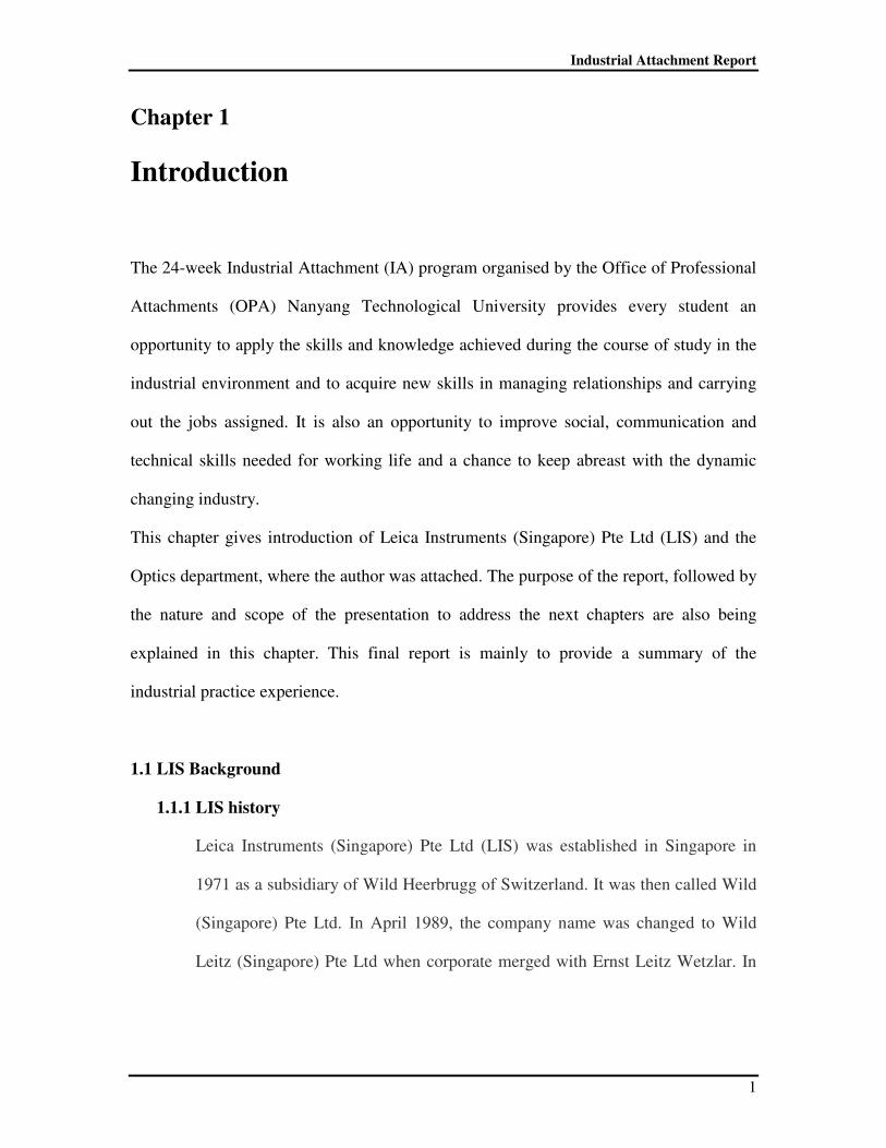
LIS was initially located at Bukit Merah Central. In 1991, LIS moved to a new
12,000 sq metres location at Teban Gardens Crescent, which was officially
opened by the late Dr Tay Eng Soon. The key milestones of the company could
be found in Appendix A.
Figure 1.1 LIS at Teban Gardens Crescent
1.1.2 LIS nature of business
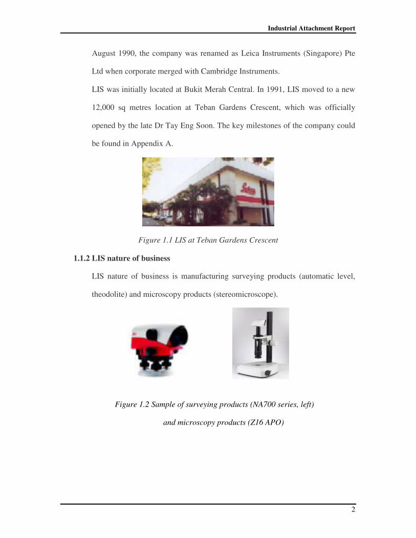
LIS nature of business is manufacturing surveying products (automatic level,
theodolite) and microscopy products (stereomicroscope).
Figure 1.2 Sample of surveying products (NA700 series, left)
and microscopy products (Z16 APO)
Industrial Attachment Report
3
LIS manufacturing processes include:
- Precision Optics - Information Technology
- Precision Machining - International Procurement Office
- Assembly Operations - Technical Service
- Research & Development
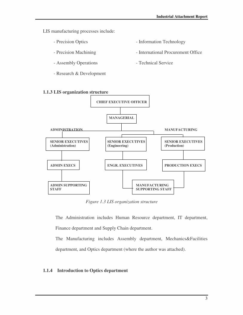
1.1.3 LIS organization structure
CHIEF EXECUTIVE OFFICER
MANAGERIAL
ADMINISTRATION MANUFACTURING
SENIOR EXECUTIVES SENIOR EXECUTIVES SENIOR EXECUTIVES (Administration) (Engineering) (Production)
ADMIN EXECS ENGR. EXECUTIVES PRODUCTION EXECS ADMIN SUPPORTING MANUFACTURING STAFF SUPPORTING STAFF
Figure 1.3 LIS organization structure
The Administration includes Human Resource department, IT department,
Finance department and Supply Chain department.
The Manufacturing includes Assembly department, Mechanics&Facilities
department, and Optics department (where the author was attached).
1.1.4 Introduction to Optics department
Industrial Attachment Report
4
The Optics department of Leica Instruments (Singapore) Pte Ltd produces
precision optical components for sub-assemblies and instruments. The focus of
the production is on the following area:
1) Plano Optics
Plane and parallel plates of any shapes, filters and mirrors. Prism with tightest
tolerances, cemented prism groups and special index matched optical groups.
2) Spherical Optics
Doublets, triples or quadruples lenses, high precision ball lenses and special
edge profile lenses with high surface accuracy, stray light reduction masking,
high efficiency functional coatings and direct air gap adjustment capability.
3) Optical Coatings
Developing and producing optical coatings like Anti-Reflection, Beamsplitter,
Mirror and Filter coatings and also special coatings.
1.2 Industrial Attachment
During the course of the Industrial Attachment, the author was working under Mr.
Charlie Ng, with Mr. Donald Ng Boon Yong as his main supervisor in the Optics
department of Leica Instruments (Singapore) Pte Ltd. The author assisted the Optics
engineering management in day-to-day operations.
The activities include designing autocollimator holder; Testing, measurement and
checking of optical parts; assisting design and outsourcing of plastic packaging.
Some documentation jobs were also done and the documentation system was learnt as
well. Computer aided design software was learnt by making drawings of some optical

Industrial Attachment Report
5
parts. Data processing jobs and assisting staffs in the optics department were done
throughout the attachment period.
1.3 Report Presentation
This report summarises the work carried out and the industrial training experience
gained by the author during the period of the Industrial Attachment up to the time this
report was documented. The discussion of the projects and jobs undertaken is divided
into two main chapters in this report. Each project comes with a background
discussion to provide better perspective for readers who are unfamiliar with the topic.
Tables, figures and diagrams are provided to enable ease of understanding of the
content.
Chapter two of this report discusses the first project that the author has dealt with,
autocollimator holder design. Chapter three will elaborate on the testing,
measurement and checking of optical parts done using various devices and
instruments. At the end of each chapter, the results obtained and their discussions are
presented. There were other jobs done by the author during the Industrial Attachment,
but they are not presented in this report due to some constraints.
The last chapter of the report will give the conclusions on the work done and
recommendations for improvements and possible next steps of work. The conclusion
includes the author’s view of the work performed and the experience gained from the
projects or jobs.
Industrial Attachment Report
6
Chapter 2
Design of Autocollimator Holder
In this chapter of the report, the project of designing the autocollimator holder is
elaborated. Firstly, the background of autocollimator usage in the process of inspection
will be explained. The problem aroused from the previous inspection method, which led
to the designing of autocollimator holder, will be discussed. Then, the process of
designing the autocollimator holder will be described. Finally, the evaluation of the final
design will be explained.
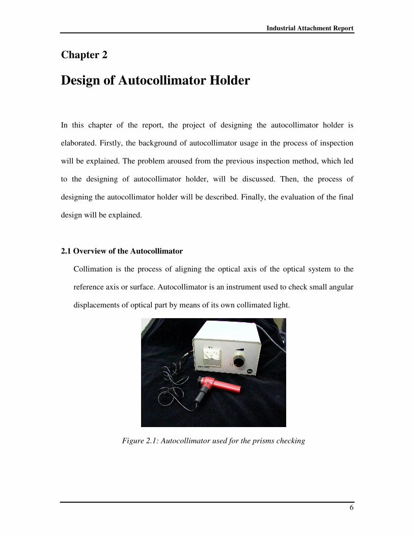
2.1 Overview of the Autocollimator
Collimation is the process of aligning the optical axis of the optical system to the
reference axis or surface. Autocollimator is an instrument used to check small angular
displacements of optical part by means of its own collimated light.
Figure 2.1: Autocollimator used for the prisms checking
Industrial Attachment Report
7
As far as this project concerned, the autocollimator is used for angle measurement of
2 types of prisms (part no: 409541 and 409542). The checking of the prisms angle is
one of the series of the inspection steps required in the prisms production.
2.2 Previous prisms angle inspection method
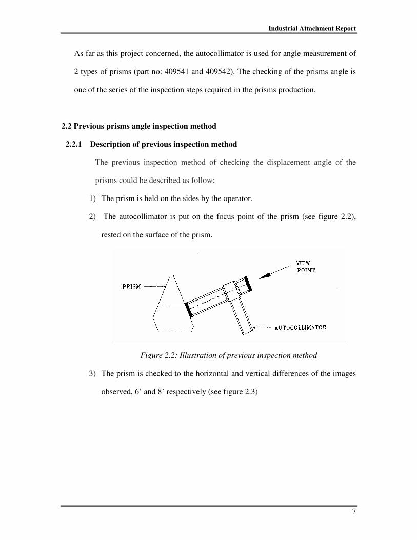
2.2.1 Description of previous inspection method
The previous inspection method of checking the displacement angle of the
prisms could be described as follow:
1) The prism is held on the sides by the operator.
2) The autocollimator is put on the focus point of the prism (see figure 2.2),
rested on the surface of the prism.
Figure 2.2: Illustration of previous inspection method
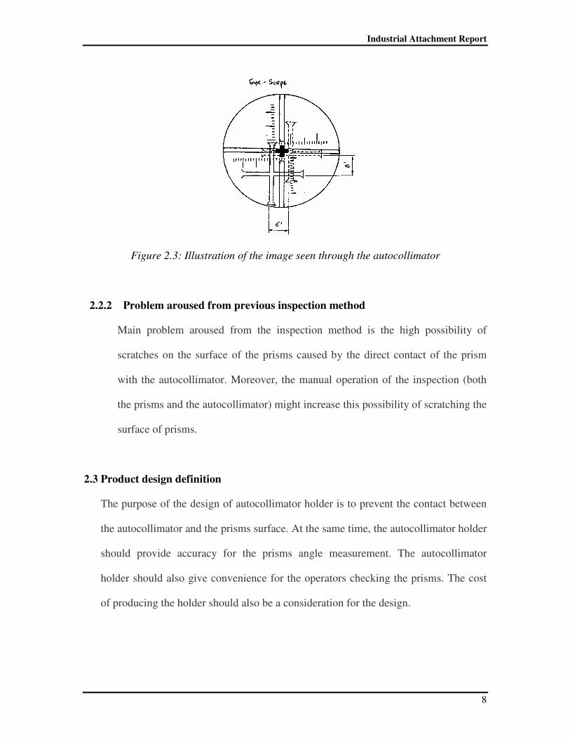
3) The prism is checked to the horizontal and vertical differences of the images
observed, 6’ and 8’ respectively (see figure 2.3)
Industrial Attachment Report
8
Figure 2.3: Illustration of the image seen through the autocollimator
2.2.2 Problem aroused from previous inspection method
Main problem aroused from the inspection method is the high possibility of
scratches on the surface of the prisms caused by the direct contact of the prism
with the autocollimator. Moreover, the manual operation of the inspection (both
the prisms and the autocollimator) might increase this possibility of scratching the
surface of prisms.
2.3 Product design definition
The purpose of the design of autocollimator holder is to prevent the contact between
the autocollimator and the prisms surface. At the same time, the autocollimator holder
should provide accuracy for the prisms angle measurement. The autocollimator
holder should also give convenience for the operators checking the prisms. The cost
of producing the holder should also be a consideration for the design.
Industrial Attachment Report
9
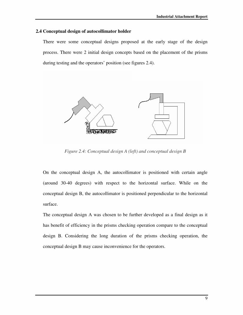
2.4 Conceptual design of autocollimator holder
There were some conceptual designs proposed at the early stage of the design
process. There were 2 initial design concepts based on the placement of the prisms
during testing and the operators’ position (see figures 2.4).
Figure 2.4: Conceptual design A (left) and conceptual design B
On the conceptual design A, the autocollimator is positioned with certain angle
(around 30-40 degrees) with respect to the horizontal surface. While on the
conceptual design B, the autocollimator is positioned perpendicular to the horizontal
surface.
The conceptual design A was chosen to be further developed as a final design as it
has benefit of efficiency in the prisms checking operation compare to the conceptual
design B. Considering the long duration of the prisms checking operation, the
conceptual design B may cause inconvenience for the operators.

Industrial Attachment Report
10
2.5 Embodiment design of the autocollimator holder
The initial design of the autocollimator holder, based on the conceptual design A,
could be divided into 5 parts. The 3D model of the assembled design, made using
SolidWorks 2003 software, is shown in figure 2.5. The details of the parts of the
initial design could be seen in the appendix.
Figure 2.5: 3D model of initial design
Some evaluation and suggestion for improvement of the initial design were made.
1. The cost of producing the design could be reduced significantly by changing the
cylindrical holder base. Rectangular holder base was suggested for the improved
design.
2. The design of the prisms holder should be improved. The placing from the front
was not possible due to the placement of autocollimator. The side placing of the
prisms was suggested for the improvement.
Industrial Attachment Report
11
2.6 Final design of the autocollimator holder
2.6.1 Completing and improving the design
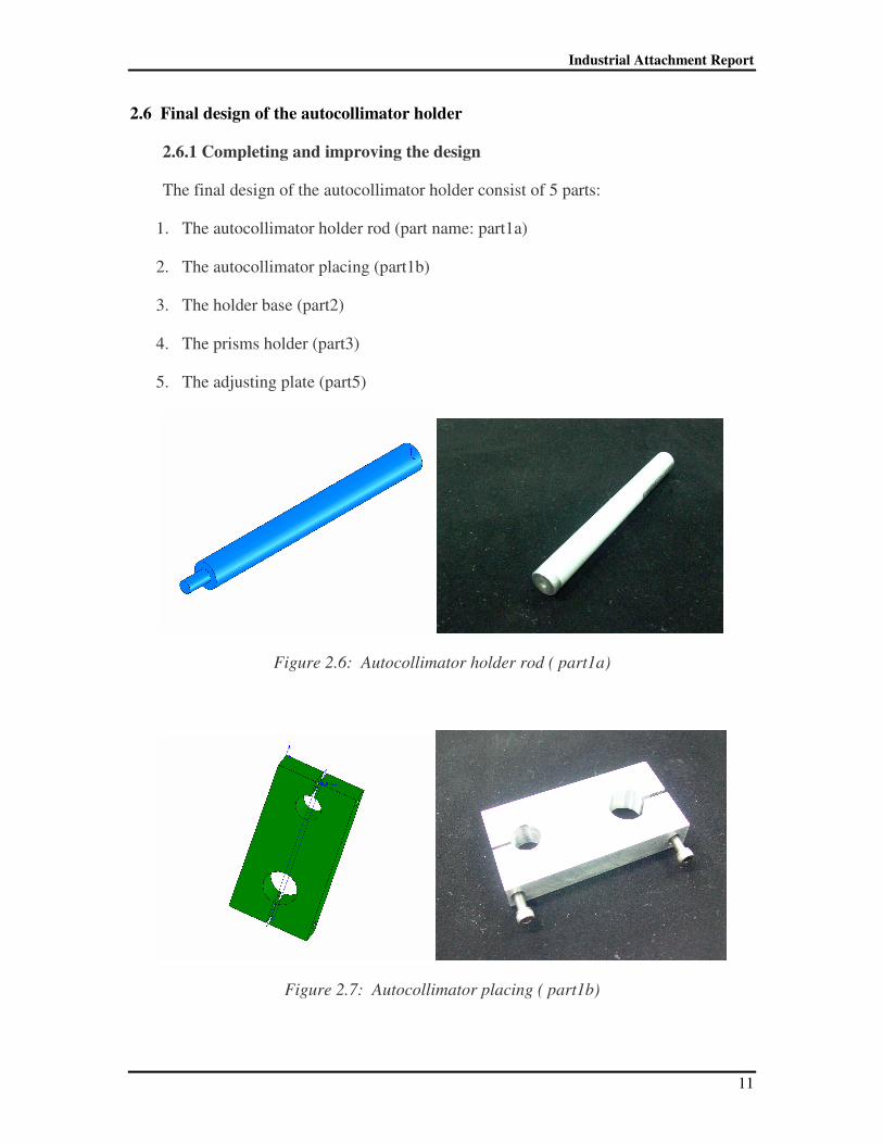
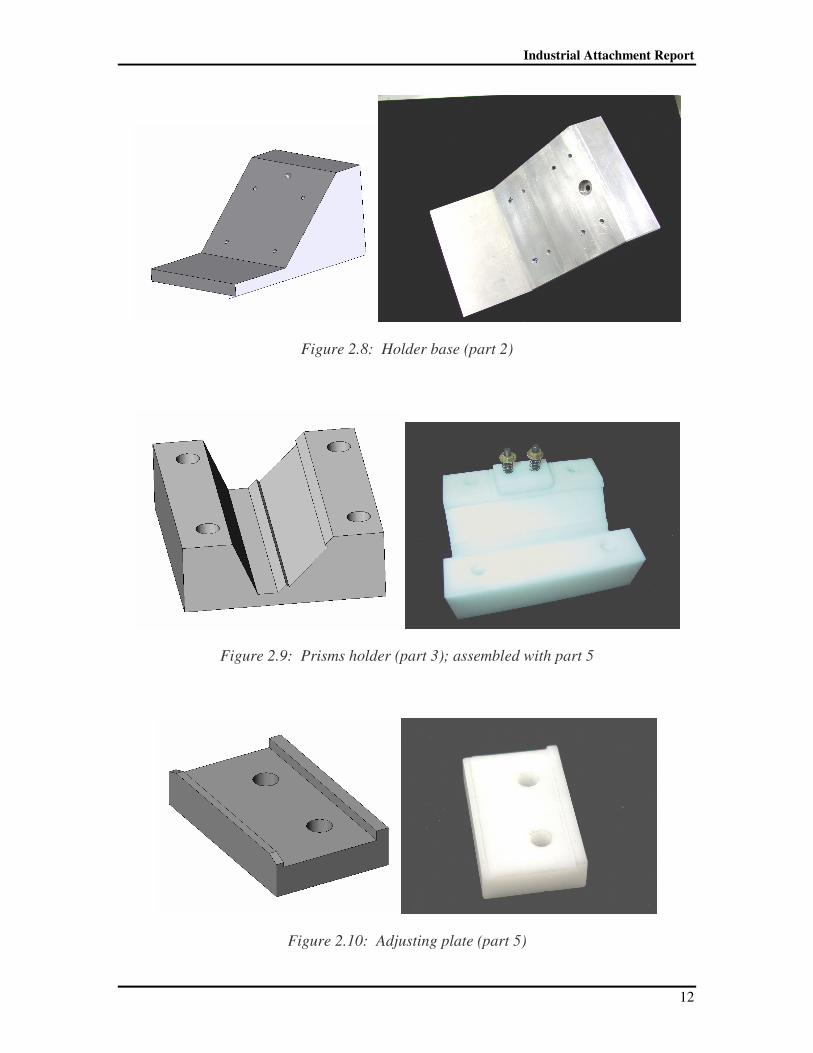
The final design of the autocollimator holder consist of 5 parts:
1. The autocollimator holder rod (part name: part1a)
2. The autocollimator placing (part1b)
3. The holder base (part2)
4. The prisms holder (part3)
5. The adjusting plate (part5)
Figure 2.6: Autocollimator holder rod ( part1a)
Figure 2.7: Autocollimator placing ( part1b)
Industrial Attachment Report
12
Figure 2.8: Holder base (part 2)
Figure 2.9: Prisms holder (part 3); assembled with part 5
Figure 2.10: Adjusting plate (part 5)
Industrial Attachment Report
13
The drawing of each of the parts above can be found in Appendix B. Due to the
some restrictions; the dimensions of the drawing are not shown.
Initially, the design consisted only of the first four parts mentioned above.
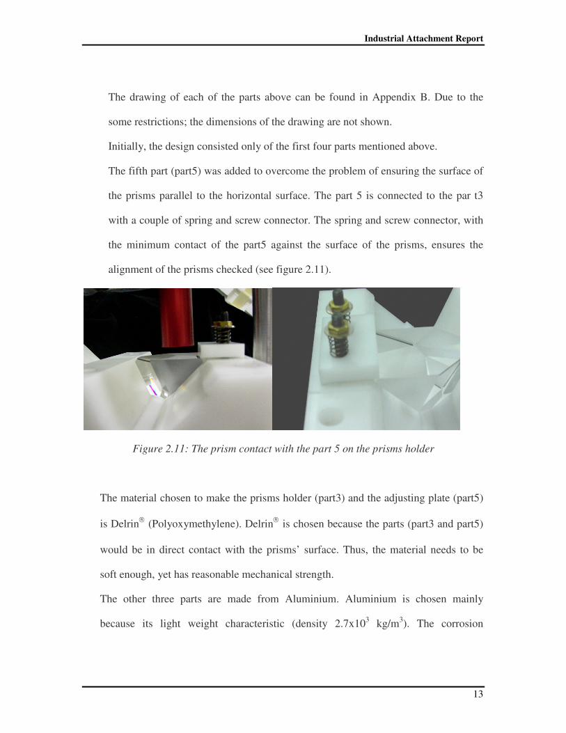
The fifth part (part5) was added to overcome the problem of ensuring the surface of
the prisms parallel to the horizontal surface. The part 5 is connected to the par t3
with a couple of spring and screw connector. The spring and screw connector, with
the minimum contact of the part5 against the surface of the prisms, ensures the
alignment of the prisms checked (see figure 2.11).
Figure 2.11: The prism contact with the part 5 on the prisms holder
The material chosen to make the prisms holder (part3) and the adjusting plate (part5)
is Delrin
(Polyoxymethylene). Delrin
is chosen because the parts (part3 and part5)
would be in direct contact with the prisms’ surface. Thus, the material needs to be
soft enough, yet has reasonable mechanical strength.
The other three parts are made from Aluminium. Aluminium is chosen mainly
because its light weight characteristic (density 2.7x10³ kg/m
3). The corrosion
Industrial Attachment Report
14
resistance and tensile strength characteristics of Aluminium are also included as
considerations in choosing the material.
The 3D model and drawing, complete with the dimensions, of each part were made
using SolidWorks 2003 software.
2.6.2 Ordering the product
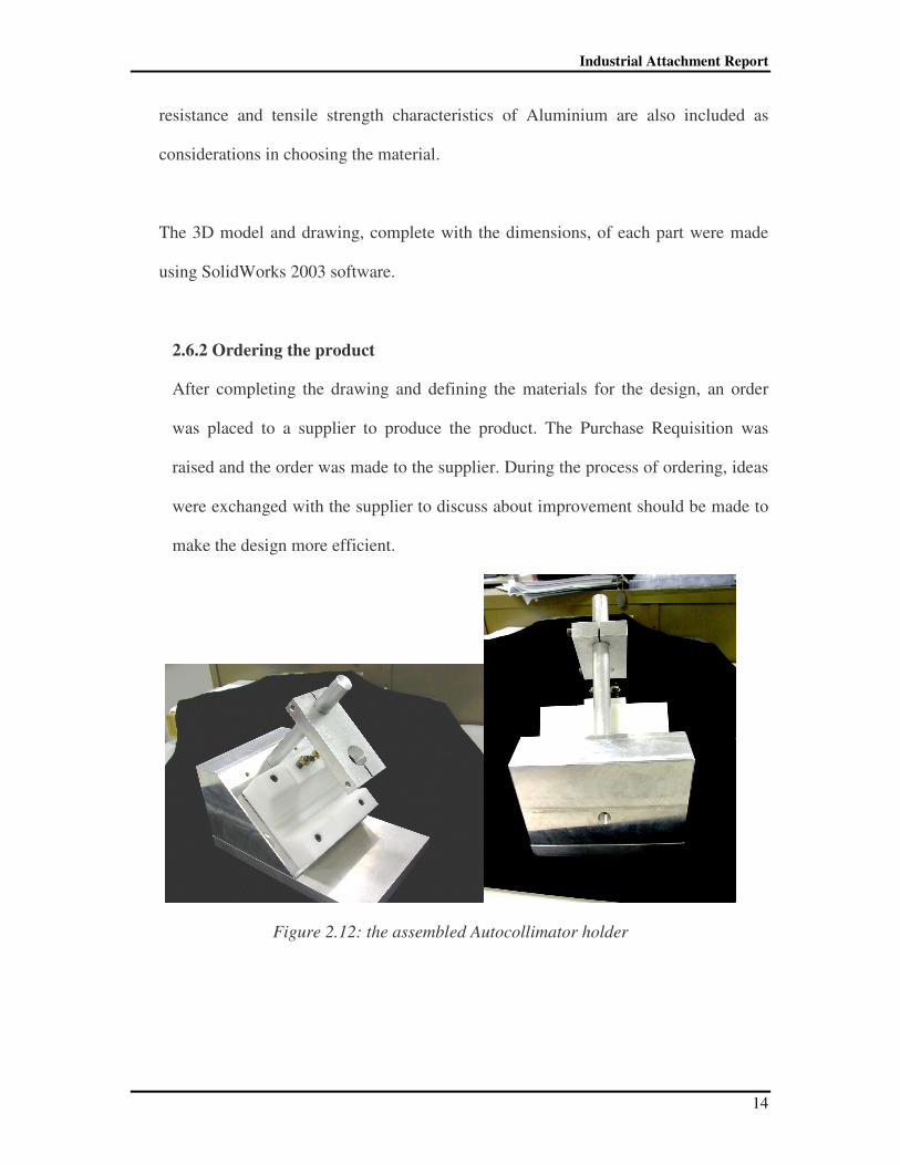
After completing the drawing and defining the materials for the design, an order
was placed to a supplier to produce the product. The Purchase Requisition was
raised and the order was made to the supplier. During the process of ordering, ideas
were exchanged with the supplier to discuss about improvement should be made to
make the design more efficient.
Figure 2.12: the assembled Autocollimator holder

Industrial Attachment Report
15
2.7 Evaluation of the autocollimator holder
The following part will elaborate the things learnt by the author during the design
process as well as the improvement that could be made for the future design.
(1) Besides the function and the ergonomic of the design, the cost of production is an
important consideration in the decision making process.
(2) The manufacturer of the product contributes to the decision making by providing
insight suggestions from the manufacturing point of view. Both of the designer
and manufacturer should discuss the best solution for the product design.
(3) To achieve higher precision and efficiency in the production process, the designer
should decide the appropriate tolerances and include them in the parts drawing.
Figure 2.13: The assembled autocollimator holder in details
(4) The designer should specify clearly the threaded holes and the screws using
international convention in the parts drawing. By doing so, misinterpretation of
the drawing could be avoided.
(5) There was slight deviation in terms of parallelism of the prisms holder (part3) and
the autocollimator placing (part1b). The deviation has significant effect on the
accuracy of the prisms checking. To justify this deviation, some small aluminium
Industrial Attachment Report
16
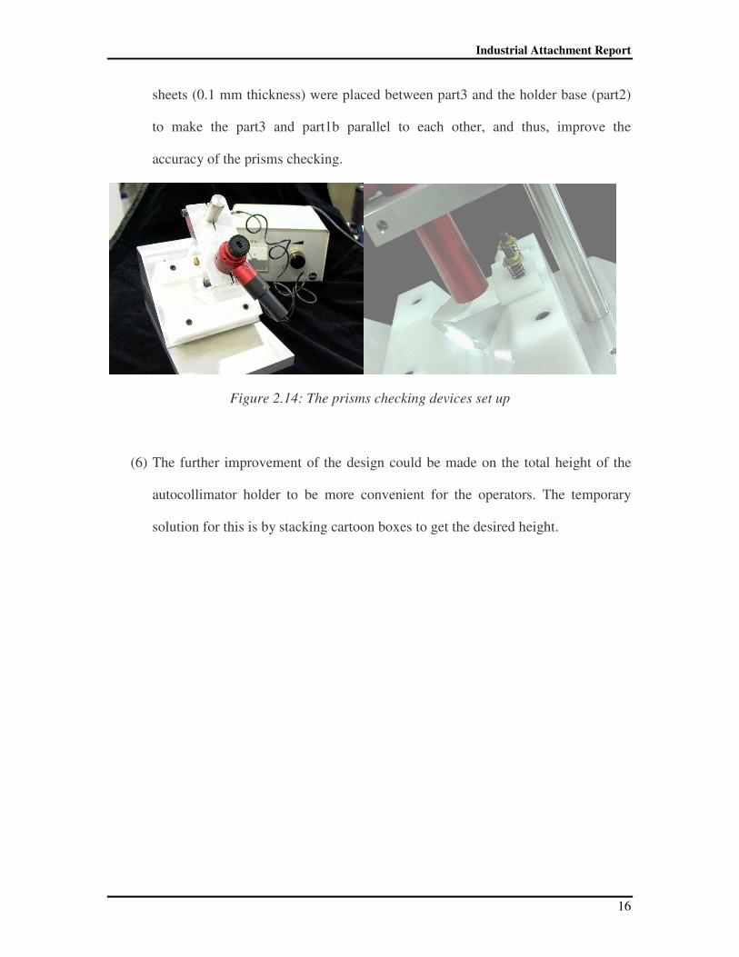
sheets (0.1 mm thickness) were placed between part3 and the holder base (part2)
to make the part3 and part1b parallel to each other, and thus, improve the
accuracy of the prisms checking.
Figure 2.14: The prisms checking devices set up
(6) The further improvement of the design could be made on the total height of the
autocollimator holder to be more convenient for the operators. The temporary
solution for this is by stacking cartoon boxes to get the desired height.
Industrial Attachment Report
17
Chapter 3
Measurement and Testing
In this chapter of the report, several jobs of optical parts measurement and testing are
presented. Though there were a lot of jobs of testing and measurement during the
Industrial Attachment period, they could be categorized in 3 groups. In the following
parts, each of the 3 groups will be described. The description includes the devices used,
the testing/measurement method as well as the evaluation and the learning process
obtained in finishing the jobs.
3.1 Measurements of Prisms Angle (part no: 19001464)
3.1.1 Overview
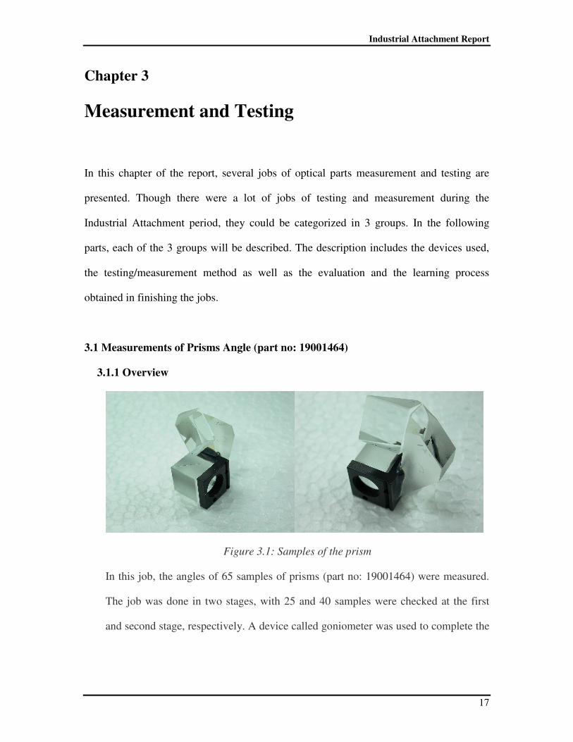
Figure 3.1: Samples of the prism
In this job, the angles of 65 samples of prisms (part no: 19001464) were measured.
The job was done in two stages, with 25 and 40 samples were checked at the first
and second stage, respectively. A device called goniometer was used to complete the
Industrial Attachment Report
18
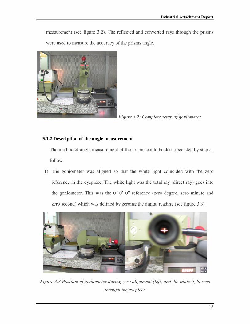
measurement (see figure 3.2). The reflected and converted rays through the prisms
were used to measure the accuracy of the prisms angle.
Figure 3.2: Complete setup of goniometer
3.1.2 Description of the angle measurement
The method of angle measurement of the prisms could be described step by step as
follow:
1) The goniometer was aligned so that the white light coincided with the zero
reference in the eyepiece. The white light was the total ray (direct ray) goes into
the goniometer. This was the 0o 0’ 0” reference (zero degree, zero minute and
zero second) which was defined by zeroing the digital reading (see figure 3.3)
Figure 3.3 Position of goniometer during zero alignment (left) and the white light seen
through the eyepiece

Industrial Attachment Report
19
2) Adjusting the measurement table to be parallel to the horizontal plane. Firstly the
goniometer was moved to 90o 0’ 0”, and the table was adjusted by turning the
panels on the sides of the table. The parallelism of the table was found by
observing the red light (the reflection ray) inside the eyepiece.
3) The goniometer was set to the 180o 0’ 0”, the setting up of the goniometer was
done.
4) The next step done was finding the parallelism of the surface of the parts with
respect to the goniometer. This was done manually by rotating and tilting the parts
slowly until the red light (the reflection ray) appeared inside of the eyepiece. This
step was experienced as the most difficult step throughout the process of the angle
prisms measurement.
5) The angle of the prism using the total ray path (white light) as reference was
found out. This was done by setting the goniometer around 30o (the ideal
dimension). Then, using the fine-tuning, the goniometer was adjusted so that the
white light coincided with the zero reference inside of the eyepiece. The reading
of the prism angle was taken from the digital reading.
6) The angle of the prism using the reflection ray path (red light) as reference was
found out. This was done by setting the goniometer around 30o (the ideal
dimension). Then, using the fine-tuning, the goniometer was adjusted so that the
red light coincided with the zero reference inside of the eyepiece. The reading of
the prism angle was taken from the digital reading. The result of the measurement
could be found in Appendix D.

Industrial Attachment Report
20
3.1.3 Evaluation and Learning Experience
They are several learning experiences gained throughout completing the job of
prism angle measurement. At the following parts, the learning experience and the
problems encountered will be elaborated.
1. During the process of completing the job, the ray path through the prisms was
learnt and observed. By this observation, the understanding about the reflected
ray and converted ray of the prism was deepened. The reflected and converted
ray is used to build the method of prisms angle measurement using goniometer.
2. Finding the parallelism of the prism surface with respect to the goniometer
manually was time consuming and difficult (step number 4). One of the ways to
make the process more efficient was by marking the table of goniometer once the
first sample had been parallel to the goniometer. Another action done was by
regularly adjusting the table after 3-4 samples were checked (repeating step 1
until 3).
3. The importance of the tolerance in the designing and producing high precision
optical parts was appreciated. With the tight tolerance of the parts to get high
accuracy, the inspection steps taken should be done carefully.
3.2 Dimension checking of samples (part no: 10721601, 10721160 and 703510)
3.2.1 Overview
In this job, the dimensions of 5 samples of Diffuser to Fresn Lens WDG29 (part no:
10721601), 7 samples of condenser_mirror (part no: 10721160) and 5 samples of
mirror (703510) were checked. The checking of 7 samples of condenser_mirror (part
Industrial Attachment Report
21
no: 10721160) was done in two stages, with 5 and 2 samples were checked at the first
and second stage, respectively. The checking results were compared to the nominal
value (including the tolerance) stated in the drawing. Though there were 3 different
parts checked, the checking process could be presented together as the principals
behind the checking of the parts are similar. The picture and sketch drawing of all the
parts could be found in Appendix E.
3.2.2 Description of the Devices Used
There were 3 devices used to check the dimensions of the samples in this job:
1. Profile projector.
2. Videoscope
3. Vernier
Throughout the process of completion the checking, various operation functions of the
devices were learnt and practiced.
The basic principles of each device could be described as follow:
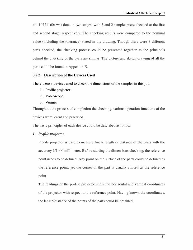
1. Profile projector
Profile projector is used to measure linear length or distance of the parts with the
accuracy 1/1000 millimeter. Before starting the dimensions checking, the reference
point needs to be defined. Any point on the surface of the parts could be defined as
the reference point, yet the corner of the part is usually chosen as the reference
point.
The readings of the profile projector show the horizontal and vertical coordinates
of the projector with respect to the reference point. Having known the coordinates,
the length/distance of the points of the parts could be obtained.
Industrial Attachment Report
22
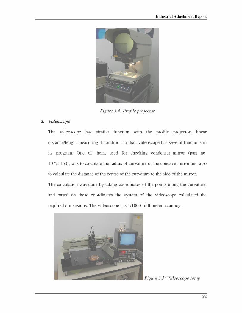
Figure 3.4: Profile projector
2. Videoscope
The videoscope has similar function with the profile projector, linear
distance/length measuring. In addition to that, videoscope has several functions in
its program. One of them, used for checking condenser_mirror (part no:
10721160), was to calculate the radius of curvature of the concave mirror and also
to calculate the distance of the centre of the curvature to the side of the mirror.
The calculation was done by taking coordinates of the points along the curvature,
and based on these coordinates the system of the videoscope calculated the
required dimensions. The videoscope has 1/1000-millimeter accuracy.
Figure 3.5: Videoscope setup

Industrial Attachment Report
23
3. Vernier
The manual vernier was used to measure the thickness of the parts (10721601 and
10721160). The accuracy of the vernier is 1/100 millimeter. The vernier was still
widely used for dimensions checking due to its efficiency for large number of
samples checking.
3.2.3 Description of the samples checking
The method of the checking of the samples could be described step by step as
follow:
1) For measuring linear dimensions, the profile projector was used. For all three
parts (10721601, 10721160 and 703510), the sample was put on the profile
projector table with the surface being checked facing the profile projector lens.
Figure 3.6: The part was put on the profile projector table
2) The focal distance of the profile projector lens was adjusted to get the best image
of the surface of the samples.
3) The sample was aligned so that its position was parallel to the reference of the
profile projector, both vertical and horizontal reference.
4) After the vertical and horizontal reference had been aligned, the reference point of
the checking was defined. In this case, the top right hand side of the surface was
taken as the reference (i.e. the zero vertical and horizontal coordinates).
Industrial Attachment Report
24
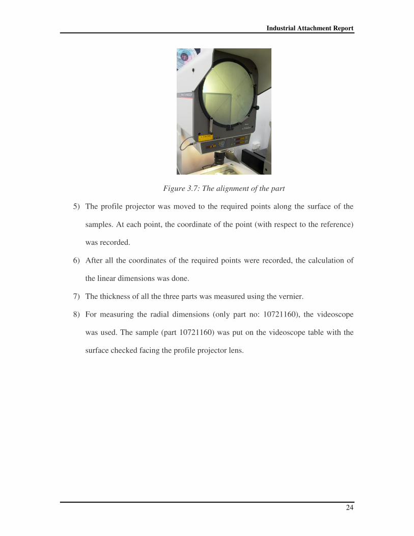
Figure 3.7: The alignment of the part
5) The profile projector was moved to the required points along the surface of the
samples. At each point, the coordinate of the point (with respect to the reference)
was recorded.
6) After all the coordinates of the required points were recorded, the calculation of
the linear dimensions was done.
7) The thickness of all the three parts was measured using the vernier.
8) For measuring the radial dimensions (only part no: 10721160), the videoscope
was used. The sample (part 10721160) was put on the videoscope table with the
surface checked facing the profile projector lens.
Industrial Attachment Report
25
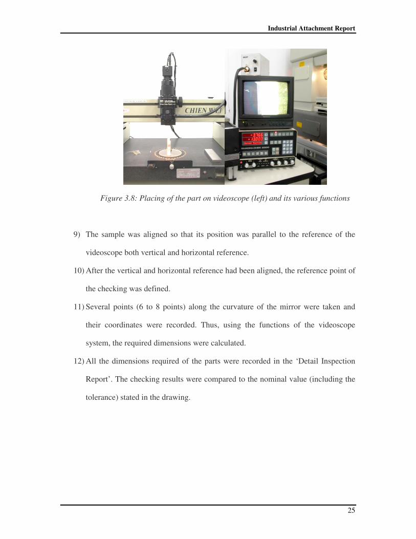
Figure 3.8: Placing of the part on videoscope (left) and its various functions
9) The sample was aligned so that its position was parallel to the reference of the
videoscope both vertical and horizontal reference.
10) After the vertical and horizontal reference had been aligned, the reference point of
the checking was defined.
11) Several points (6 to 8 points) along the curvature of the mirror were taken and
their coordinates were recorded. Thus, using the functions of the videoscope
system, the required dimensions were calculated.
12) All the dimensions required of the parts were recorded in the ‘Detail Inspection
Report’. The checking results were compared to the nominal value (including the
tolerance) stated in the drawing.

Industrial Attachment Report
26
3.2.4 Evaluation and Learning Experience
They are several learning experiences gained throughout completing the job of
dimension checking of samples. At the following parts, the learning experience and
the problems encountered will be elaborated.
1. Due to the inhomogeneity of the samples produced by the suppliers, there were
some of the samples not qualified based on the nominal value of the dimensions
stated in the drawing of the parts. The results of the dimension checking would
be used in decision making of the outsourcing of the parts in the future.
2. The importance of the tolerance in the outsourcing of the optical parts was
appreciated. Since the results of the dimension checking would be used in
decision making of the outsourcing (which includes costing), the inspection steps
taken should be done carefully.
3.3 Using Interferometer for Radius and Irregularity Checking
3.3.1 Overview
The device named ‘interferometer’ is derived from the word interference. Interference
is a phenomenon that occurs when two waves take place at the same time. It could be
any kind of waves, sound waves, light waves, ocean waves, or seismic waves from
earthquakes.
Interference can be visualized as the resultant of the two waves. Depending on
amplitude and the degree to which the waves are in or out of step with each other
(phase difference), they will either add together or cancel each other.

Industrial Attachment Report
27
If both waves are in step or in phase, the two will add together to form a single wave.
This combined wave will have larger amplitude In the case of light waves, two
dimmer light beams will add together to form a brighter beam, called constructive
interference. On the other hand, destructive interference occurs when the two waves
are out of phase with each other. Here, when waves are added together, they actually
cancel each other out.
Figure 3.9: Illustration of constructive and destructive interference
Hence, the amount of interference that occurs depends on both the amplitudes of the
two waves and the degree to which their respective peaks and troughs are in phase
with each other.
An interferometer is an optical device making use of the interference phenomena to
obtain information about the optical parts concerned. Though there are many different
types and designs of interferometers in the market, most of them operate on the same
basic principle.
Industrial Attachment Report
28
From a beam of light coming from the light wave source e.g. laser, lamp, etc., two or
more flat mirrors are used to split off different light beams. These beams are then
combined so as to interfere with each other.
In the optical industry, the interference of two or more light waves is widely used for
various applications. In this job, the interference phenomenon was used to check the
radius and irregularity of test glass.
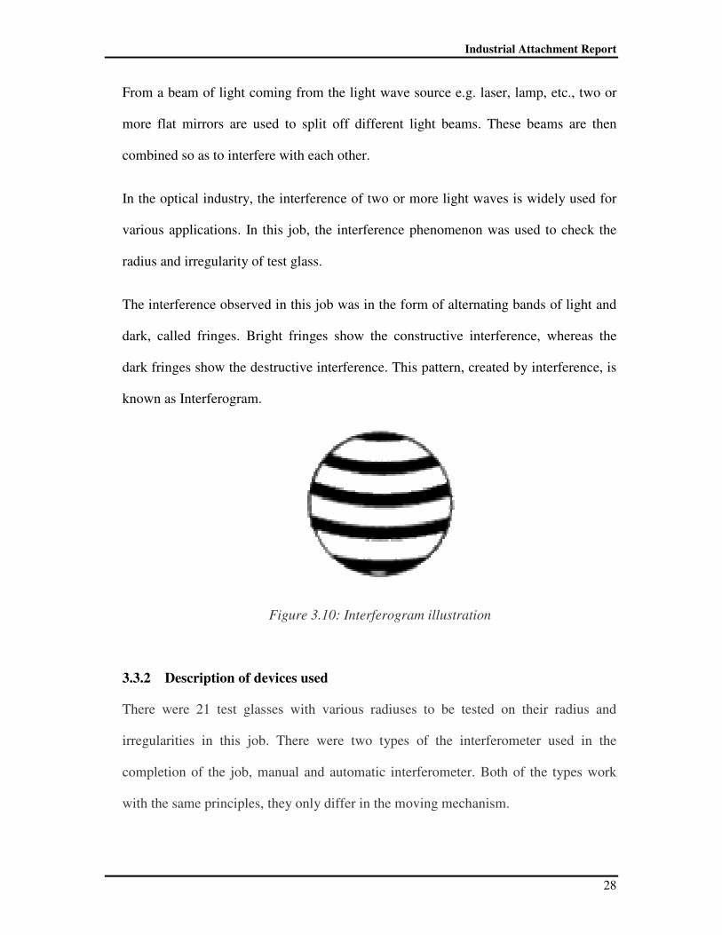
The interference observed in this job was in the form of alternating bands of light and
dark, called fringes. Bright fringes show the constructive interference, whereas the
dark fringes show the destructive interference. This pattern, created by interference, is
known as Interferogram.
Figure 3.10: Interferogram illustration
3.3.2 Description of devices used
There were 21 test glasses with various radiuses to be tested on their radius and
irregularities in this job. There were two types of the interferometer used in the
completion of the job, manual and automatic interferometer. Both of the types work
with the same principles, they only differ in the moving mechanism.
Industrial Attachment Report
29
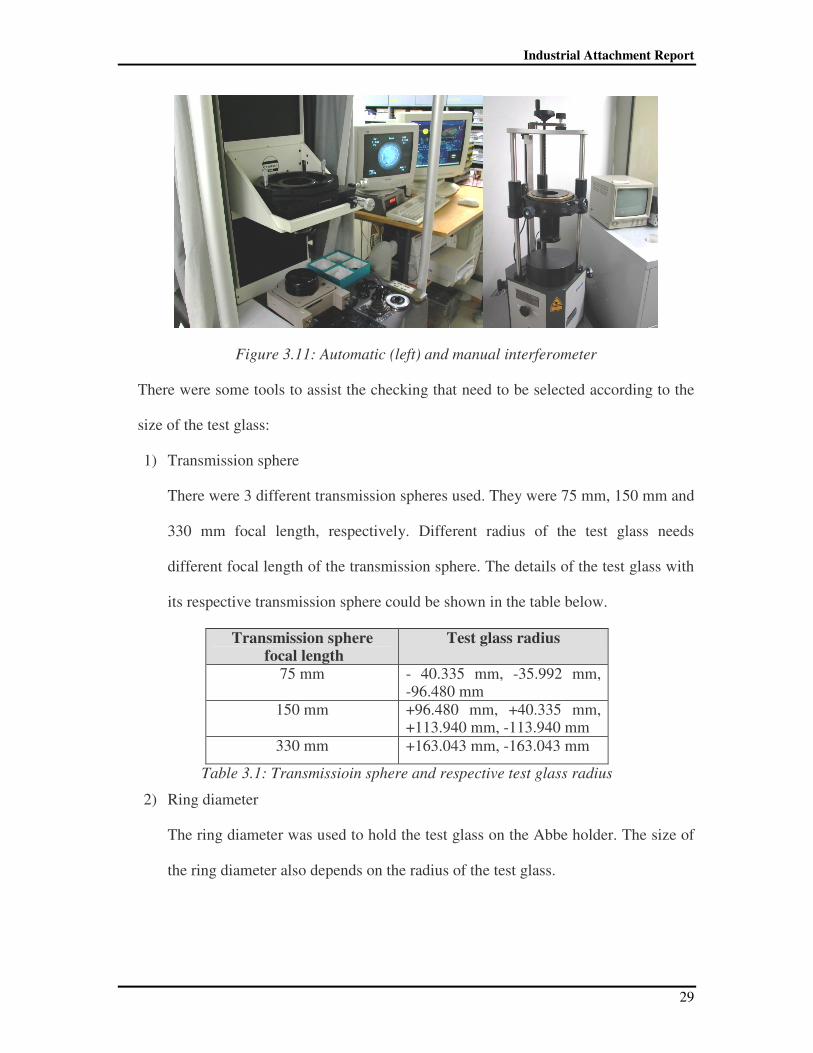
Figure 3.11: Automatic (left) and manual interferometer
There were some tools to assist the checking that need to be selected according to the
size of the test glass:
1) Transmission sphere
There were 3 different transmission spheres used. They were 75 mm, 150 mm and
330 mm focal length, respectively. Different radius of the test glass needs
different focal length of the transmission sphere. The details of the test glass with
its respective transmission sphere could be shown in the table below.
Transmission sphere focal length
Test glass radius
75 mm - 40.335 mm, -35.992 mm, -96.480 mm
150 mm +96.480 mm, +40.335 mm, +113.940 mm, -113.940 mm
330 mm +163.043 mm, -163.043 mm
Table 3.1: Transmissioin sphere and respective test glass radius
2) Ring diameter
The ring diameter was used to hold the test glass on the Abbe holder. The size of
the ring diameter also depends on the radius of the test glass.
Industrial Attachment Report
30
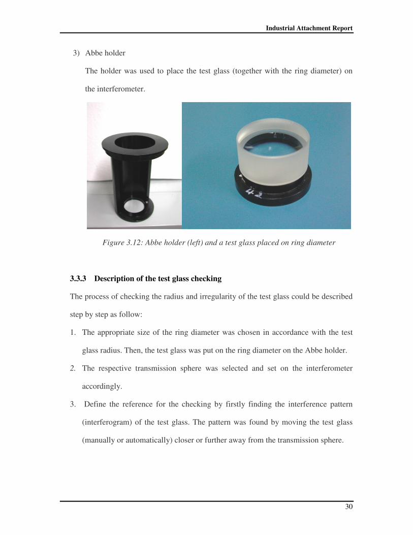
3) Abbe holder
The holder was used to place the test glass (together with the ring diameter) on
the interferometer.
Figure 3.12: Abbe holder (left) and a test glass placed on ring diameter
3.3.3 Description of the test glass checking
The process of checking the radius and irregularity of the test glass could be described
step by step as follow:
1. The appropriate size of the ring diameter was chosen in accordance with the test
glass radius. Then, the test glass was put on the ring diameter on the Abbe holder.
2. The respective transmission sphere was selected and set on the interferometer
accordingly.
3. Define the reference for the checking by firstly finding the interference pattern
(interferogram) of the test glass. The pattern was found by moving the test glass
(manually or automatically) closer or further away from the transmission sphere.
Industrial Attachment Report
31
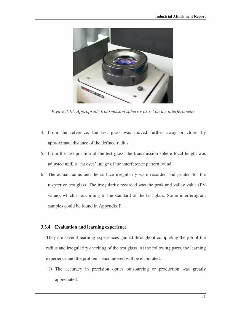
Figure 3.13: Appropriate transmission sphere was set on the interferometer
4. From the reference, the test glass was moved further away or closer by
approximate distance of the defined radius.
5. From the last position of the test glass, the transmission sphere focal length was
adjusted until a ‘cat eyes’ image of the interference pattern found.
6. The actual radius and the surface irregularity were recorded and printed for the
respective test glass. The irregularity recorded was the peak and valley value (PV
value), which is according to the standard of the test glass. Some interferogram
samples could be found in Appendix F.
3.3.4 Evaluation and learning experience
They are several learning experiences gained throughout completing the job of the
radius and irregularity checking of the test glass. At the following parts, the learning
experience and the problems encountered will be elaborated.
1) The accuracy in precision optics outsourcing or production was greatly
appreciated.
Industrial Attachment Report
32
2) The relationship among the focal length of the test glass, interference
phenomenon and the radius checking was appreciated and understood.
3) There was problem encountered in finding the interference due to the limitation
of the height of the manual interferometer. To overcome this problem, the
automatic interferometer was used.
4) Finding the ‘cat eyes’ interference pattern was difficult due to the absence of
the standard, thus approximate approach was done to complete the job.
Industrial Attachment Report
33
Chapter 4
Conclusions
The period of attachment with Leica Instruments (S) Pte Ltd has helped the author gain
enormous technical knowledge and insightful experiences in a real working environment.
The most rewarding experience is to be part of the company culture.
There were adequate opportunities to put theories and principles learnt in the
undergraduate course at NTU. The programme required interaction with a wide range of
people in the engineering profession as well as other related fields, including
administrative staff and outside parties (e.g. supplier), thus allowing for valuable human
relations skills to be developed.
A great hands-on experience of designing autocollimator holder was gone through by the
author. The appreciation of all the aspects of design was achieved and gained. The author
was given the opportunity to deal with the supplier and exchange ideas for more effective
design of the autocollimator holder. This exposure of the design process has helped to
advance the author’s designing and management skills.
Various testing and measurement of optical parts were done using various devices and
methods. Measurement of prisms angle, dimensions checking of optical parts, as well as
radius and irregularity test glass testing were completed. Throughout the process of
completing the jobs, appreciation about the accuracy of the optical parts was gained. The
Industrial Attachment Report
34
importance of the careful inspection of the optical parts was appreciated. With the help
and guidance from the supervisor and the engineers, the author was able to complete the
testing and measurement effectively.
There were several other jobs completed during the period of the Industrial Attachment
that are not presented in this report. These jobs include the documentation of the optics
department data, producing the drawings using the computer aided design software, data
processing jobs and assisting the engineers in day-to-day operation.
These various projects and jobs undertaken by the author have allowed the author to gain
a deeper insight into the technical and practical aspects of precision optics engineering.
As inculcated by the culture of the company, the author has learnt to adopt a systematic
approach to an engineering problem and explore the numerous ways for the best solution
and have been successfully applied to those projects undertaken. The 24-week Industrial
Attachment in Leica Instruments (S) Pte Ltd Optics department has indeed been a fruitful
and pleasant experience.
Industrial Attachment Report
35
References and Readings
Frey, David. AUTOCAD 2000 No Experience Required. USA, 1999. Sybex.
Karow, Hank. Fabrication Methods For Precision Optics. USA, 1993. John Wiley & Sons, Inc.
Pfaender, Heinz. Schott Guide to Glass. United Kingdom, 1996. Chapman&Hall.
www.kentek-laser.com/helpers/glossary.htm www.merckmedicus.com www.leica.com Leica Instruments (S) Pte Ltd leaflets and brochures.
Related Documents