Computational Visual Media https://doi.org/10.1007/s41095-020-0172-x Vol. 6, No. 2, June 2020, 169–189 Research Article Saliency-based image correction for colorblind patients Jinjiang Li 1,2 ( ), Xiaomei Feng 1,2 , and Hui Fan 1,2 c The Author(s) 2020. Abstract Improper functioning, or lack, of human cone cells leads to vision defects, making it impossible for affected persons to distinguish certain colors. Colorblind persons have color perception, but their ability to capture color information differs from that of normal people: colorblind and normal people perceive the same image differently. It is necessary to devise solutions to help persons with color blindness understand images and distinguish different colors. Most research on this subject is aimed at adjusting insensitive colors, enabling colorblind persons to better capture color information, but ignores the attention paid by colorblind persons to the salient areas of images. The areas of the image seen as salient by normal people generally differ from those seen by the colorblind. To provide the same saliency for colorblind persons and normal people, we propose a saliency-based image correction algorithm for color blindness. Adjusted colors in the adjusted image are harmonious and realistic, and the method is practical. Our experimental results show that this method effectively improves images, enabling the colorblind to see the same salient areas as normal people. Keywords color vision; colorblindness; saliency; color correction 1 Introduction With the development of printing and screen display technology, color has become an important means of information exchange in people’s daily life. Information exchange through color is convenient 1 School of Computer Science and Technology, Shandong Technology and Business University, Yantai 264005, China. E-mail: J. Li, [email protected] ( ); X. Feng, [email protected]; H. Fang, [email protected]. 2 Co-innovation Center of Shandong Colleges and Universities: Future Intelligent Computing, Yantai 264005, China. Manuscript received: 2020-02-26; accepted: 2020-03-31 for ordinary people but is more of a challenge for those with color vision defects (CVD). CVD can cause various changes in color perception, from slight shadows to severely indistinguishable colors. CVD are of three main kinds: red-green color blindness, blue-yellow color blindness, and complete color blindness. Most CVD are congenital, affecting approximately one in every 40,000 newborn babies. However, these defects may also be caused by abnormal development of cone cells in the retina, or external damage. Currently, there are at least 200 million persons worldwide with dichromatic CVD, of which approximately 3.5% are school students. The prevalence of generalized CVD is even more difficult to assess. CVD are easily overlooked because many people think that these problems are not serious. However, most types of color blindness make it very difficult to distinguish, e.g., changes in traffic lights, which is very dangerous. Many other areas can be affected by these defects, such as the ability to read traffic signs and maps. To ensure the wellbeing and safety of colorblind persons, the problem of color blindness should not be ignored. Solutions to the problem of CVD are of two main kinds: treatment of the person, and augmentation of images. Regarding the treatment of persons with CVD, certain physical therapies are generally used to reduce the effects of CVD and complications, but CVD often cannot be cured. For example, in one type of advanced treatment, a red light is used to stimulate the color perception of the cone cells. However, the success rate of this treatment is only 35%. Image- based CVD solutions start outside the human body, processing images by computer and presenting the results to the colorblind person. Such methods avoid pain for the person and have high feasibility. There are many methods for overcoming CVD based on images. In color scheme adjustment [1–3], 169

Welcome message from author
This document is posted to help you gain knowledge. Please leave a comment to let me know what you think about it! Share it to your friends and learn new things together.
Transcript
Computational Visual Mediahttps://doi.org/10.1007/s41095-020-0172-x Vol. 6, No. 2, June 2020, 169–189
Research Article
Saliency-based image correction for colorblind patients
Jinjiang Li1,2 (�), Xiaomei Feng1,2, and Hui Fan1,2
c© The Author(s) 2020.
Abstract Improper functioning, or lack, of human conecells leads to vision defects, making it impossible foraffected persons to distinguish certain colors. Colorblindpersons have color perception, but their ability tocapture color information differs from that of normalpeople: colorblind and normal people perceive the sameimage differently. It is necessary to devise solutionsto help persons with color blindness understand imagesand distinguish different colors. Most research onthis subject is aimed at adjusting insensitive colors,enabling colorblind persons to better capture colorinformation, but ignores the attention paid by colorblindpersons to the salient areas of images. The areas ofthe image seen as salient by normal people generallydiffer from those seen by the colorblind. To providethe same saliency for colorblind persons and normalpeople, we propose a saliency-based image correctionalgorithm for color blindness. Adjusted colors in theadjusted image are harmonious and realistic, and themethod is practical. Our experimental results show thatthis method effectively improves images, enabling thecolorblind to see the same salient areas as normal people.
Keywords color vision; colorblindness; saliency; colorcorrection
1 IntroductionWith the development of printing and screen displaytechnology, color has become an important meansof information exchange in people’s daily life.Information exchange through color is convenient
1 School of Computer Science and Technology, ShandongTechnology and Business University, Yantai 264005,China. E-mail: J. Li, [email protected] (�); X. Feng,[email protected]; H. Fang, [email protected].
2 Co-innovation Center of Shandong Colleges andUniversities: Future Intelligent Computing, Yantai264005, China.
Manuscript received: 2020-02-26; accepted: 2020-03-31
for ordinary people but is more of a challenge forthose with color vision defects (CVD). CVD cancause various changes in color perception, fromslight shadows to severely indistinguishable colors.CVD are of three main kinds: red-green colorblindness, blue-yellow color blindness, and completecolor blindness. Most CVD are congenital, affectingapproximately one in every 40,000 newborn babies.However, these defects may also be caused byabnormal development of cone cells in the retina,or external damage. Currently, there are at least 200million persons worldwide with dichromatic CVD, ofwhich approximately 3.5% are school students. Theprevalence of generalized CVD is even more difficultto assess. CVD are easily overlooked because manypeople think that these problems are not serious.However, most types of color blindness make it verydifficult to distinguish, e.g., changes in traffic lights,which is very dangerous. Many other areas can beaffected by these defects, such as the ability to readtraffic signs and maps. To ensure the wellbeing andsafety of colorblind persons, the problem of colorblindness should not be ignored.Solutions to the problem of CVD are of two main
kinds: treatment of the person, and augmentationof images. Regarding the treatment of persons withCVD, certain physical therapies are generally usedto reduce the effects of CVD and complications, butCVD often cannot be cured. For example, in one typeof advanced treatment, a red light is used to stimulatethe color perception of the cone cells. However, thesuccess rate of this treatment is only 35%. Image-based CVD solutions start outside the human body,processing images by computer and presenting theresults to the colorblind person. Such methods avoidpain for the person and have high feasibility.There are many methods for overcoming CVD
based on images. In color scheme adjustment [1–3],
169
170 J. Li, X. Feng, H. Fan
brightness differences can be used to realize automaticcolor conversion. Ref. [4] used an ordinarystereo display (non-autostereo display) to providecolorblind persons and ordinary users with two visualexperiences, so that CVD and normal vision viewerscan share the same content. A wearable visionimprovement system [5] can enhance a person’sIshihara vision test score with enhanced mechanicalequipment and a head-mounted display. Color filters[6] have been used for auxiliary color recognition forthe colorblind, moving color filters [7–9] in front of theperson’s eyes to achieve rapid conversion between filmobservation and naked eye observation. For example,if you move the green film, the green color is notaffected, but the red transmittance is reduced, whichforms a region where the brightness continuouslychanges, helping the colorblind person to discriminatecolors. Another static filter [10] converts the diffusestate of the color into an identifiable state. A moreadvanced method [11] uses a Heilmeier-type liquidcrystal device to control the transmittance of greenlight by changing the voltage to achieve synchronousflashing of green objects.An auxiliary color filter device transmits different
colors through a film, thereby forming a colordifference, but this method is only used for a certaincolorblind tube, and different standards are requiredfor different types of color blindness. It may not be
usable in all cases. Wearable visual improvementtechnology is effective in improving the vision ofpersons with color vision defects, but the need tocarry and wear the necessary equipment may beinconvenient.People pay attention to the salient regions when
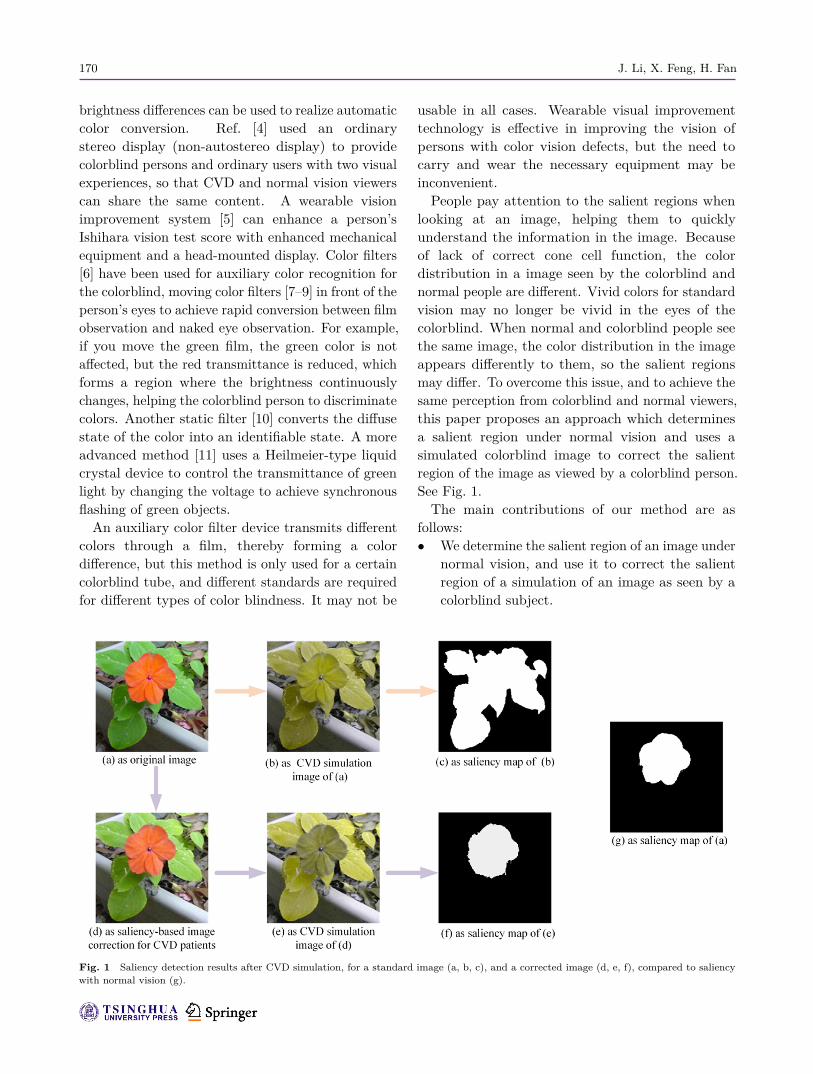
looking at an image, helping them to quicklyunderstand the information in the image. Becauseof lack of correct cone cell function, the colordistribution in a image seen by the colorblind andnormal people are different. Vivid colors for standardvision may no longer be vivid in the eyes of thecolorblind. When normal and colorblind people seethe same image, the color distribution in the imageappears differently to them, so the salient regionsmay differ. To overcome this issue, and to achieve thesame perception from colorblind and normal viewers,this paper proposes an approach which determinesa salient region under normal vision and uses asimulated colorblind image to correct the salientregion of the image as viewed by a colorblind person.See Fig. 1.The main contributions of our method are as
follows:• We determine the salient region of an image under
normal vision, and use it to correct the salientregion of a simulation of an image as seen by acolorblind subject.
Fig. 1 Saliency detection results after CVD simulation, for a standard image (a, b, c), and a corrected image (d, e, f), compared to saliencywith normal vision (g).
Saliency-based image correction for colorblind patients 171
• We retain the original color of the image tohighlight the salient area. Adjusted colors inthe adjusted image are harmonious and realistic,and the method is practical.
2 Related work2.1 Color vision defectsHuman color perception is based on three light-sensitive pigments [12, 13] and may be representedby a three-dimensional value, the power of eachwavelength specifying the degree of the color stimulus.Trichromatic accuracy is determined by three typesof light-sensitive pigment cells (L-, M-, and S-cones)in the retina. Different wavelengths of light stimulatethe receptors differently. For example, yellow-greenlight stimulates L-cones and M-cones to the samedegree, but only weakly stimulates S-cones. Thehuman visual system combines information fromvarious cone cells in response to light of differentwavelengths. When any kind of cone cell is destroyedor loses function [14], color vision defects occur.CVD can be divided into color blindness and
color weakness, and described as trichromacy(color weakness), bichromacy (color blindness), ormonochromacy (full-color blindness). Persons withfull-color blindness have lost functionality of two orthree kinds of cone-cell and can perceive the intensityof light [15] but cannot distinguish colors; they seethe world in black and white. Certain colorblindpersons with bichromacy have lost red, green, or bluecone functions. Certain persons with trichromacyhave functioning cones of all three kinds, but one ofthe photosensitivity spectra is shifted, thus causing adeviation in color perception.
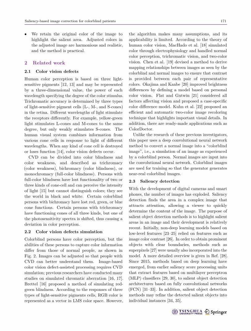
2.2 Color vision defects simulationColorblind persons have color perception, but theabilities of these persons to capture color informationdiffer from those of normal people, as shown inFig. 2. Images can be adjusted so that people withCVD can better understand them. Image-basedcolor vision defect-assisted processing requires CVDsimulation; previous researchers have conducted manystudies on simulated chromatic aberration [16, 17].Brettel [16] proposed a method of simulating red-green blindness. According to the responses of threetypes of light-sensitive pigments cells, RGB color isrepresented as a vector in LMS color space. However,
the algorithm makes many assumptions, and itsapplicability is limited. According to the theory ofhuman color vision, MacHado et al. [18] simulatedcolor through electrophysiology and handled normalcolor perception, trichromatic vision, and two-colorvision. Chen et al. [19] devised a method to derivemapping relationships between images as seen by thecolorblind and normal images to ensure that contrastis provided between each pair of representativecolors. Okajima and Kanbe [20] improved brightnessdifferences by defining a model based on personalcolor vision. Flat and Gutwin [21] considered allfactors affecting vision and proposed a case-specificcolor difference model. Kuhn et al. [22] proposed anefficient and automatic two-color image recoloringtechnique that highlights important visual details. Inaddition, there are ready-made applications such asColorDoctor.Unlike the research of these previous investigators,
this paper uses a deep convolutional neural networkmethod to convert a normal image into a “colorblindimage”, i.e., a simulation of an image as experiencedby a colorblind person. Normal images are input intothe convolutional neural network. Colorblind imagesare used for training so that the generator generatesnear-real colorblind images.
2.3 Saliency detectionWith the development of digital cameras and smartphones, the number of images has exploded. Saliencydetection finds the area in a complex image thatattracts attention, allowing a viewer to quicklydetermine the content of the image. The purpose ofsalient object detection methods is to highlight salientareas in an image and their development is relativelyrecent. Initially, non-deep learning models based onlow-level features [23–25] relied on features such asimage color contrast [26]. In order to obtain prominentobjects with clear boundaries, methods such assuperpixels [27] were usually also incorporated into themodel. A more detailed overview is given in Ref. [28].Since 2015, methods based on deep learning haveemerged, from earlier saliency score processing unitsthat extract features based on multilayer perceptron(MLP) classifiers [29, 30], to salient object detectionarchitectures based on fully convolutional networks(FCN) [31–33]. In addition, salient object detectionmethods may refine the detected salient objects intoindividual instances [34, 35].
172 J. Li, X. Feng, H. Fan
In addition to research on static scenes, salientobject detection in dynamic scenes has also flourished:e.g., Ref. [36] has contributed to research onvideo saliency. Salient object detection can notonly detect salient objects, but also has a widerange of applications, including unsupervised videoobject segmentation [37], semantic segmentation[38, 39], automatic image cropping [40], image targetretargeting [41], and other fields.In this paper, saliency detection is performed to find
the salient area. Traditional contrast-based objectdetection methods have limitations, overemphasizingthe edges of the salient object without uniformlydistributing saliency across the salient object. Whenthe current experience is similar to the background,saliency detection errors arise. In order to alleviatethese problems, this paper adopts a diffusion-basedmethod [42], using the diffusion matrix and seedvector for salient area detection.
2.4 Saliency-based image processingWhen we take a photo on a mobile phone, wesometimes find that an unimportant object is tooprominent, distracting from the original intent. Facedwith this kind of problem, we may wish to takeanother shot or fix the photo later. However, it iscomplicated to enhance specific objects in a photousing an image editor. It is necessary to consider theexposures of specific objects, reduce the backgroundexposure, and increase saturation and backgroundblur. For those lacking basic knowledge of color
Fig. 2 Top: color spectrum as seen with normal vision. Next 6 rows:the three main types of color blindness paired with their less severeversions. Bottom: monochromatic vision.
matching, this method is difficult. To solve thisproblem, we can learn the parameters of an imageusing a network and adjust the contrast of the targetarea, and other image parameters. This approachof improving the apparent contrast of an object bymanipulating the color of the image is called attentionredirection [43, 44]. In addition to enhancing salience,object enhancement can be achieved through thisidea [45], guiding viewers to pay attention to mixedreality [46] and color redirection [47] or augmentingimages by removing the background [48], emphasizingthe background [49], or changing image aesthetics[50]. Through attention-focused operations, objectsof interest are made more prominent, and it iseasier for people with color defects to find prominentobjects.The goal of attention redirection is to select the
target area and correct this area to achieve targetenhancement. Various methods are compared inRef. [43]. Certain methods enhance objects in sucha way that the enhanced color is unrealistic, e.g.,resulting in a purple apple or a blue snake. Anotherpatch-based approach [51] replaces patches in thetarget area with other patches from the same image.This replacement is not simple patch exchange. Basedon the saliency of the image, an appropriate patchis selected for replacement, thereby enhancing thetarget area of the image to achieve a significanteffect.
3 Colorblind images3.1 Colorblind image correctionCurrently, there is no effective treatment for colorblindness. In recent years, with the developmentof technology, various colorblind image re-coloringalgorithms have appeared, providing color correctionfor colorblind images. Because of the defects incone cells of colorblind persons, some colors areunrecognizable, so the main purpose of colorblindcolor correction is to help colorblind personsdistinguish certain colors, rather than helpingcolorblind persons recognize certain colors. In orderto do so, increasing the color contrast betweendifferent colors is the main approach to colorblindimage correction.These methods may be mainly divided into four
categories: LMS space conversion, colorblind filters,
Saliency-based image correction for colorblind patients 173
Lab color correction, and shifting color algorithms.LMS space conversion is a more comprehensivemethod which converts the image from RGB spaceto LMS space, processes the image in LMS space,and re-converts the processed image to RGB space.The CBFS algorithm compares the color of eachpixel in the image with red or green, and processesthe approximately red or green pixels, so that acolorblind person can better perceive the image. Thiscorrection algorithm is aimed at protanopia. Labcolor correction converts RGB images into Lab space,and modifies the sensitive red or green color forgreen blind persons, thus achieving color correctionof colorblind images. This method only corrects fordeuteranopia. The shifting color method is aimed attritanopia. It converts the image to Lab space, adjuststhe image brightness, and then adjusts and convertsback to RGB color space to achieve color correction.The above methods have various problems, such as
unnatural coloring, artifacts in coloring results, andslowness. Huang et al. [52] proposed a more efficientimage re-coloring algorithm. A Gaussian mixturemodel (GMM) is used to represent color information.Extracted key colors are weighted to take into accountthe sensitivity of colorblind persons to different colors.During interpolation, color is interpolated accordingto the posterior probability of the Gaussian and thecorresponding map, thereby ensuring smoothness oflocal colors in the image after re-coloring, effectivelyreducing artifacts.
3.2 Colorblind image saliency detectionBecause of the defects in cone function, colorblindpersons are unable to recognize or distinguish certaincolors. When a normal and a colorblind person seethe same image, the former is attracted to bright red,while the latter’s attention is concentrated in otherareas. If they discuss this image, they concentrate ondifferent aspects.For most color images, the color seen by CVD
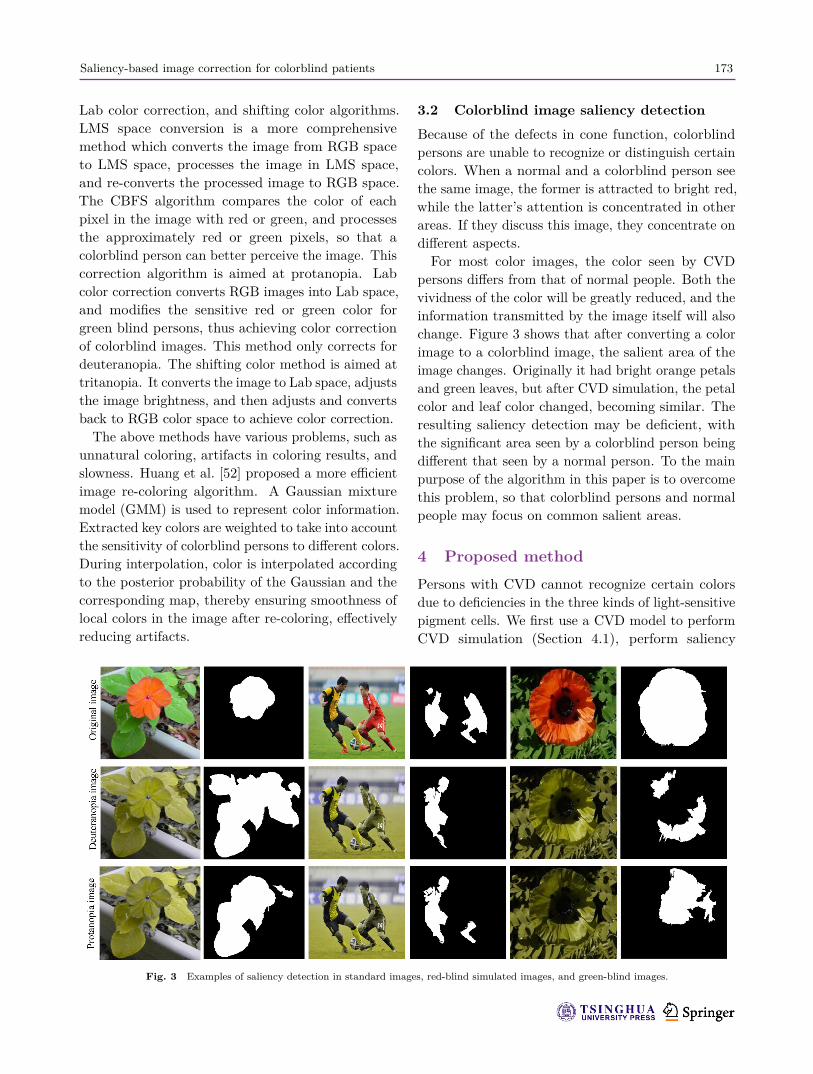
persons differs from that of normal people. Both thevividness of the color will be greatly reduced, and theinformation transmitted by the image itself will alsochange. Figure 3 shows that after converting a colorimage to a colorblind image, the salient area of theimage changes. Originally it had bright orange petalsand green leaves, but after CVD simulation, the petalcolor and leaf color changed, becoming similar. Theresulting saliency detection may be deficient, withthe significant area seen by a colorblind person beingdifferent that seen by a normal person. To the mainpurpose of the algorithm in this paper is to overcomethis problem, so that colorblind persons and normalpeople may focus on common salient areas.
4 Proposed methodPersons with CVD cannot recognize certain colorsdue to deficiencies in the three kinds of light-sensitivepigment cells. We first use a CVD model to performCVD simulation (Section 4.1), perform saliency
Fig. 3 Examples of saliency detection in standard images, red-blind simulated images, and green-blind images.

174 J. Li, X. Feng, H. Fan
detection on the standard image (Section 4.2), thenuse the saliency map to perform saliency correctionon the colorblind image (Section 4.3), and finallyinversely transform the corrected colorblind imageinto a standard color image (Section 4.4). The goalis that both persons with CVD and normal personsshould pay attention to the same salient area in thecorrected image. The algorithm pipeline is shown inFig. 4.
4.1 Colorblind image simulationTanuwidjaja et al. [5] proposed a wearable augmentedreality system based on Google Glass. For eachcolor, the RGB color space is converted into LMSspace. Using Eq. (1), the converted chromaticityautomatically adapts to the scene viewed accordingto the type of color blindness. There are specialalgorithms for reproducing color. Chroma’s wearableaugmented reality device is an effective digitalaccessory that enhances vision in everyday activitiesto help colorblind persons recognize different colors.⎡
⎢⎣Lcb
Mcb
Scb
⎤⎥⎦ =
⎡⎢⎣17.88 43.51 4.118.78 23.54 3.820.02 0.18 1.46
⎤⎥⎦
⎡⎢⎣
R
G
B
⎤⎥⎦ (1)
Machado et al. [18] proposed a physiological
model for simulating color perception based onelectrophysiological research report: human colorvision can be simulated to achieve normal color vision,abnormal trichromatic vision, and dichroic vision. Thismethod simulates a colorblind image using Eq. (2):⎡
⎢⎣Rs
Gs
Bs
⎤⎥⎦ = Γ−1
normalΓCV D
⎡⎢⎣
R
G
B
⎤⎥⎦ (2)
where Γ consists of the basic color sets WS(λ), YB(λ),RG(λ).Lin et al. [53] convert an RGB image to λ, Y-B,
R-G color space via LMS space, using the CIECAM02model, as below:⎡⎢⎢⎣
λ
Y-BR-G
⎤⎥⎥⎦ =
⎡⎢⎢⎣
0.347 0.598 −0.365−0.007 −0.113 −1.1851.185 −1.570 0.383
⎤⎥⎥⎦
⎡⎢⎣
R
G
B
⎤⎥⎦(3)
However, there is a certain amount of distortionin this method, and a method of recoloring thecolorblind image is proposed.The λ, Y-B, R-G spatial images are subjected to
CVD simulation to obtain a difference image, thefeature vector is extracted from the simulated image,and the color of the image after CVD simulation is
Fig. 4 Pipeline of our proposed saliency-based image correction algorithm for colorblind persons.

Saliency-based image correction for colorblind patients 175
altered so that a CVD person can perceive the colorinformation better.The simulated colorblind image can also be
inversely transformed into an RGB image, using⎡⎢⎣
R
G
B
⎤⎥⎦ =
⎡⎢⎣
1.225 −0.221 0.4820.901 −0.364 −0.267
−0.093 −0.807 0.022
⎤⎥⎦
⎡⎢⎣
λ
Y-BR-G
⎤⎥⎦(4)
Color constraints are added to minimize thedistortion caused by spatial transformation, and thealtered color is converted from λ, Y-B, R-G space toRGB space [53], to achieve recoloring.The aim during color transformation is to preserve
color information in the original image as much aspossible so that the recolored image is as natural aspossible, and the whole image is harmonious in color.When recoloring colorblind images, most methodsare based on experimental criteria. The designeruses a color scheme to reduce the limited CVD colorpalette. However extensive effort is still necessary tochoose a color that is visually friendly to the CVDviewer. Moreover, these methods cannot be applied toexisting natural images. Semiautomatic restorationof the image to accommodate color blindness providesthe user with certain parameters to adjust the colormap. However, the results are sensitive to the choiceof parameters, and inappropriate parameters cancause the images to look unnatural.
4.2 Saliency mapFirst, we abstract the image to obtain a super-pixelform of the image. Each pixel can be regardedas a node Vi in a graph G. The weight of edgeeij linking adjacent nodes Vi and Vj is used to
represent the relationship between the nodes, wherethe node represents attributes in the image. Thek-means algorithm is used to cluster the super-pixels,and the foreground and background are obtainedfrom the tightness of the cluster. The saliencymap is calculated according to the foreground andbackground seeds obtained, and then all saliencymaps are obtained by the diffusion method. Thecalculated foreground is integrated with the super-pixel saliency map of the background to produce asuper-pixel-level saliency map.Using the diffusion method, a sparse graph is
constructed from the graph nodes and the neighborsof each node. After considering neighboring nodes,the largest common edge of the node is included in thestatistical range. In this method, a two-layer sparsegraph is constructed that effectively uses local spatialrelationships in the image and removes redundantnodes as much as possible. We use the edge weightto represent the relationships between the nodes, asbelow:
wij ={
e−‖li−lj‖2/σ2, vi and vj are connected
0, otherwise(5)
After transforming from RGB color space to Labspace, li and lj represent the super-pixel means ofthe corresponding nodes vi and vj , and σ is the trade-off parameter.The nodes in the super-pixel are clustered into k
classes by the k-means algorithm with cluster centersC = |c1, · · · , ck|. For each cluster, the similaritybetween nodes and clusters is determined using themethod of popularity ranking [55]:
H = (D − αW )−1A (6)
Fig. 5 (a) Convolutional neural network framework. (b) Structure of the generator.

176 J. Li, X. Feng, H. Fan
where A indicates the similarity between vi and ci, W
is the weight set for each side, D represents the sumof the weights on all node branches, H = [hij ]N×K isthe similarity matrix after the diffusion process, andα is a constant.Using the similarity between nodes and clusters,
the significance of nodes in the region is determinedaccording to their probability; they are divided intosignificant nodes and background nodes. The salientnode-set and the background node-set are calledFG and BG, respectively. The nodes in FG forma saliency map according to
sFG(i) =N∑
j=1q(i, j)(D − αW )−1
∑cj∈FG
p(j)aij (7)
where q(i, j) is the normalization of the node weights,and p(j) is the probability that vj is a salient node.The formula shows that as the node weight wij
connected to the super-pixel node vi becomes larger,or djj for pixel vj becomes larger, the larger q(i, j)becomes, and the greater the probability that vj is asalient node.Referring to the saliency map construction method
for the salient region, the saliency map for thebackground node is formed by
SBG = (D − αW )−1∏
cj∈BG(1 − aij) (8)
The diffusion process for salient and backgroundnodes ends, forming a super-pixel saliency cluster anda background cluster. These parameters are SFG andSBG, respectively, and the two parts complement eachother to form a saliency map for the entire image.
4.3 Saliency driven color correctionTo perform color correction in a region, we adjust thesignificant contrast of the target area to the rest of theimage. We replace the patch block of the target areawith the patch block outside the target area. Thecorrected image J is generated by inputting the targetarea mask R and the green blind image I, and thesaliency contrast ΔS. The saliency of J is representedby SJ . First, we select two patch datasets of sizen × n in the input image. The patches are classifiedinto significant patches D+ = {q;SI(q) � τ+} andbackground patches D− = {q;SI(q) � τ−} whereτ−, τ+ is a threshold. The patch is manipulated bydefining an energy function to enhance the significantpatches, and the background patches are weakened.The energy function is defined as
E(J, D+, D−)
= E+ + E− + λ · E∇ (9)
E+ (J, D+)
=∑q∈R
minp∈D+D(q, p)
E− (J, D−)
=∑q /∈R
minp∈D−D(q, p)
E∇(J, I) = ∇J − ∇I2
where D(q, p) is the sum of the squared distancesbetween the patches q, p in Lab color space, E∇ isthe gradient of the original image I, and λ is used toweight the Lab color space and the original image.To obtain a colorblind image I with saliency
contrast SJ , Eq. (9) is minimized so that the moreprominent the patch in R is, the less significant thearea outside R is. Therefore, by definingψ (SJ , R) = mean
βtop{SJ ∈ R} − mean
βtop{SJ /∈ R} (10)
where βtop = 20%, the function can calculate thedifference in saliency between the pixels in the targetregion R and the external pixels and further obtainthe minimized energy term based on the saliency:
Emin =‖ ψ (SJ , R) − ΔS ‖ (11)Through greedy search, the patch library iscontinuously updated, as is the threshold, therebyupdating the entire image and realizing colorcorrection and thus enhancement of the salient regionof the colorblind image. Experimental results areshown in Figs. 6(a) and 6(e).
4.4 Inverse transformationThe method in Section 4.3 achieves saliency correctionof colorblind images, but our ultimate goal is toobtain a saliency corrected standard color image.Therefore, the corrected colorblind image must beinversely transformed into a standard color image.
Fig. 6 Colorblind image correction. (a) Effect of enhancing greenblindness; (e) effect of enhancing red blindness; (b, f): (a, e) convertedto standard color images, respectively; (c, g) colorblind simulatedimages of (b, f), respectively; (d, h) saliency maps of (c, g), respectively.
Saliency-based image correction for colorblind patients 177
Conversion between normal and colorblind images is avisual problem that can be addressed by convolutionalneural networks. For example, Ref. [56] used agenerative adversarial network to generate realisticshadows for a source object. Unlike in traditionalmethods, we determine the mapping relationshipbetween two different kinds of images through thenetwork to perform conversion of colorblind imagesto color images.Since the problem is an image-to-image conversion
problem, the convolutional neural network is trainedwith the idea of confronting the network. We assumethat the normal image is the X domain and thecolorblind image is the Y domain. Our target is Gyx :Y → X. A colorblind image is input to the network,and a standard color image corresponding to theimage is output. As shown in Fig. 5(a), the networkis divided into two branches. In order to facilitateunified training, a cyclic consistent loss function [54]is used to connect the two branches into a large cyclicnetwork.The CycleGAN structure model performs
unsupervised image style transfer, using a relativelysimple network structure. The generator anddiscriminator are unchanged in structure. In thispaper, in order to enable the generator to learn moredeep features, we use a combination of up-sampling,a residual block, and down-sampling: see Fig. 5(b).Due to the fast convergence and strong featureextraction capability of the residual network, highquality images are generated. The generator usestwo down-sampling convolutional layers with a stepsize of 2, six residual blocks, and two up-samplingconvolutional layers with a step size of 1/2. Trainingtakes 200 epochs.In this network, the forward loop network and
the backward loop network are trained using thesame loss function by using a cycle consistency lossfunction in two separate countermeasure networks.The training goal for the discriminator for asingle generator in the forward network is tomake the image generated by the generator asunrecognizable as possible to the discriminator,thereby maximizing the discriminator. The forwardloss is minGxymaxDy LGAN (Gxy, Dy, X, Y ), the lossfunction corresponding to the backward network isminGyxmaxDxLGAN (Gyx, Dx, X, Y ), and the cycleconsistency loss function is
Lcyc(Gxy, Gyx) = Ex∼pdata(x)[‖ Gyx(Y ) − x ‖2]
+Ey∼pdata(y)[‖ Gxy(X) − y ‖2]
(12)where E(∗) denoted expected value, pdata(x) is thetarget distribution of the X domain, and pdata(y) isthe target distribution of the Y domain.The forward network loss function, the backward
network loss function, and the cycle consistency lossfunction are accumulated in three parts. The overallloss function of the network is given by
L (Gxy, Gyx, Dx, Dy) = LGAN (Gxy, DY , X, Y )+LGAN (Gyx, DX , X, Y ) + λLcyc (Gxy, Gyx)
(13)where λ = 10 is a trade-off parameter.The training goal of the network isargminGxy,Gyx maxDx,Dy L (Gxy, Gyx, Dx, Dy).In Fig. 5, the corrected colorblind image is regarded
as a Y domain, input into the network, and acorrected standard color image is output. In thebackward network, the Y domain image is the input,and Y → Gyx → Gyx(Y ) → Gxy → y ≈ Y , therebyrealizing conversion of the colorblind image to anormal image: see Figs. 6(b) and 6(f). This completessaliency correction of the colorblind image.The overall method flow is given in Algorithm 1.
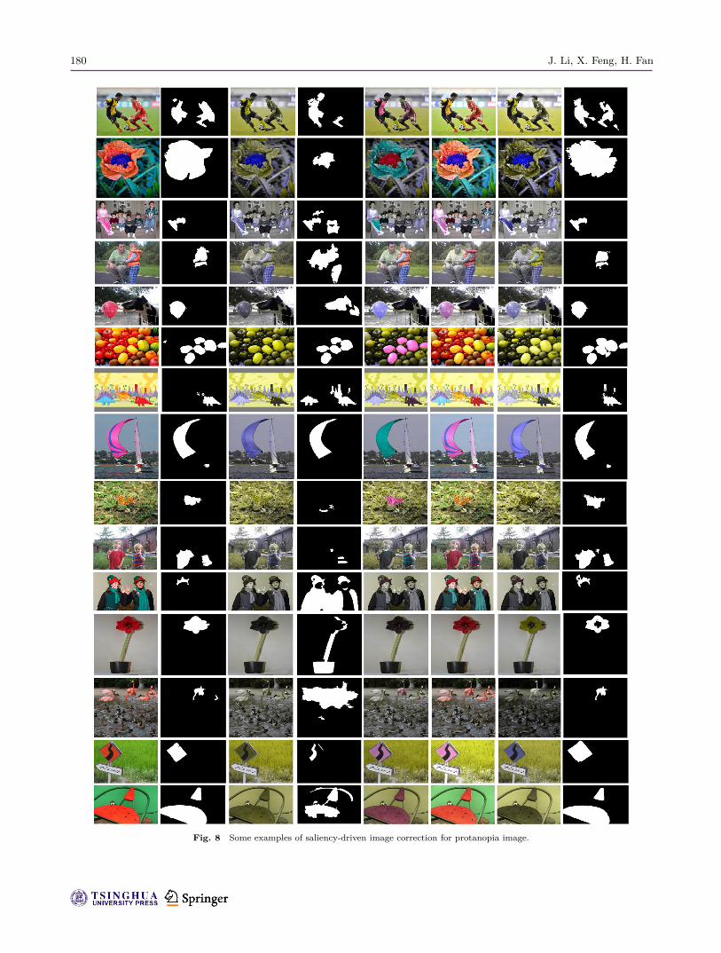
5 ExperimentsIn order to prove the effectiveness of the proposedmethod, images processed by our method arecompared to unprocessed images. Test imagescontain flowers, fruit, pedestrians, and naturalscenery. Figure 7 shows saliency driven imagecorrection for deuteranopia, while Fig. 8 showssaliency driven image correction for protanopia.The subfigures in Fig. 7 are referred to as 1–15,while subfigures in Fig. 8 are referred to as 16–30.Columns from left to right are the original image,saliency detection results for the original image, thecolorblind simulation image, the saliency detectionresult for the colorblind images, the colorblind imageswith significant area enhancement, the inverselytransformed saliency enhanced colorblind images(back to standard color), colorblind simulations ofthe restored color images, and significance detectionin that inversely transformed image.Our experimental results show that after converting
a color image into a colorblind image, the salient

178 J. Li, X. Feng, H. Fan
Algorithm 1 Saliency-based image correction for color blindnessInput: Normal color image Inorm and CVD simulation image of normal image I
1. Input: Image Inorm, Image I, and saliency contrast ΔS
2. Output: Manipulated and corrected image E
3. Initialize Inorm = (V, E),V = {vi|1 � i � N},E = {eij |1 � i, j � N},τ+, τ−
4. if p(j) > ε then5. p(j) ∈ F G
6. else7. p(j) ∈ BG
8. Make a saliency map of the salient nodes and the background nodes according to Eqs. (7) and (8)9. Object mask R = Norm(Sfg + Sbg)10. while ‖ ψ (SJ , R) − ΔS ‖> ε∗ do11. (i) Update patch library12. Increase τ+ and τ− decrease13. (ii) Image update14. Minimize Eq. (9)15. end while16. Fine-scale refinement17. When τ+ and τ− no longer change, the iteration ends, and a color-corrected colorblind image J is obtained.18. J inversely transforms a colorblind image into a color image E through a convolutional neural network.∗Norm(·) is a function that normalizes its argument to a range of 0 to 1.
region of the image may move, or the size of thesalient region may be reduced, making the salientregion less noticeable. Our algorithm performs colorcorrection on the salient region of the image to helpcolorblind persons to better perceive the image andunderstand the information conveyed by the image.Unlike traditional color correction algorithms,
the focus of this paper is not to correct thecolorblind image as a whole, but to focus on colorcorrection of the salient region of the image, sothat colorblind persons and normal people sharea common salient region. Traditional colorblindcolor correction algorithms mainly adjust those colorsthat colorblind persons cannot distinguish. Colorsin the the adjusted image are more vivid and thecontrast is more obvious, which effectively helpscolorblind persons to distinguish colors. But cancolor correction algorithms help colorblind personsto better understand images and capture the salientregion of images?To answer this question, we compare our method
with the color correction algorithm proposed byHuang et al. [52]. Experimental results are shown inFig. 9 (for green blind images) and Fig. 10 (for redblind images). Columns from left to right show: theoriginal image, the salient area of the original image,the color corrected image using our method, theCVD simulation image corresponding to the corrected
image, the saliency map for the CVD simulation,color corrected image using Huang’s algorithm, itsCVD simulation image, and its corresponding saliencymap. Comparing the second and fourth columnsin Figs. 9 and 10, it can be seen that the colorcorrection algorithm can help persons with colorvision defects to effectively distinguish colors, butthe conventional color correction algorithm cannotprovide comprehensive perception of the image forcolorblind persons.
5.1 Qualitative analysis
The experimental results provide qualitativecomparisons for different kinds of images. In theexperiment, after the original images were subjectedto CVD simulation, the vivid color information inthe original images was lost to varying degrees. Forexample, red and green turned gray or grayish-brownunder the vision of a colorblind person. Therefore,for normally visually bright colors, colorblind personsseverely lose color information, and objects becomeless noticeable. In this case, the colorblind personmisjudges the true salient area. A comparisonbetween the second and fourth columns of Figs. 7and 8 confirms this notion.In this paper, saliency-based correction of
colorblind images is achieved using the salient regionof the original image and the colorblind image for

Saliency-based image correction for colorblind patients 179
Fig. 7 Some examples of saliency-driven image correction for deuteranopia image.
180 J. Li, X. Feng, H. Fan
Fig. 8 Some examples of saliency-driven image correction for protanopia image.

Saliency-based image correction for colorblind patients 181
Fig. 9 For the deuteranopia image, compare our method with Huang’s color correction algorithm.

182 J. Li, X. Feng, H. Fan
Fig. 10 For the protanopia image, compare our method with Huang’s color correction algorithm.
Saliency-based image correction for colorblind patients 183
saliency, to obtain a corrected salient region, as inthe fifth columns of Figs. 7 and 8. The correctedcolor strongly contrasts with the color of the rest ofthe image and is significantly more notable. However,this corrected color depends on the entire image. It isuncontrollable, and the color of the corrected portiondoes not match the hues of the rest of the image and isunrealistic. Therefore, the color-corrected colorblindimage is inversely transformed into a color image.Since the correction of the salient area color is
based on the overall color of the image, if colorcorrection is performed directly on the original image,the corrected color may still be color-insensitive red,so color correction has no effect. In order to avoidthis phenomenon, color correction is performed onthe colorblind image, and the corrected colorblindimage is inversely transformed into a normal colorimage. The sixth columns of Figs. 9 and 10 showthe effect of color correction directly on the originalimage. The color-corrected image has problems suchas incomplete coloring and artifacts. The color-corrected image is subjected to CVD simulation, andthe simulated result is significantly detected; thedetection result differs largely from the real image.Comparing the second and eighth columns of
the experimental results shows that the salientregions are basically consistent, demonstrating theeffectiveness of our method. For images with blurredimage boundaries and backgrounds, after colorblindsimulation, the salient area and the background areaare more difficult to distinguish. For colorblindpersons, the salient area cannot be correctly identified.The saliency-driven color correction method proposedin this paper is resimulated. The colorblind imageis compared with the colorblind simulation imageof the original image. As shown in Fig. 7 and thethird and seventh columns of Fig. 8, the salient areashave changed to different degrees, making the areasmore obvious and original. In comparison to theCVD simulation results (see the fourth and eighthcolumns of Figs. 7 and 8) the proposed methodrediscovers the significant area that was originallyignored, making the colorblind image saliency testresult more accurate.
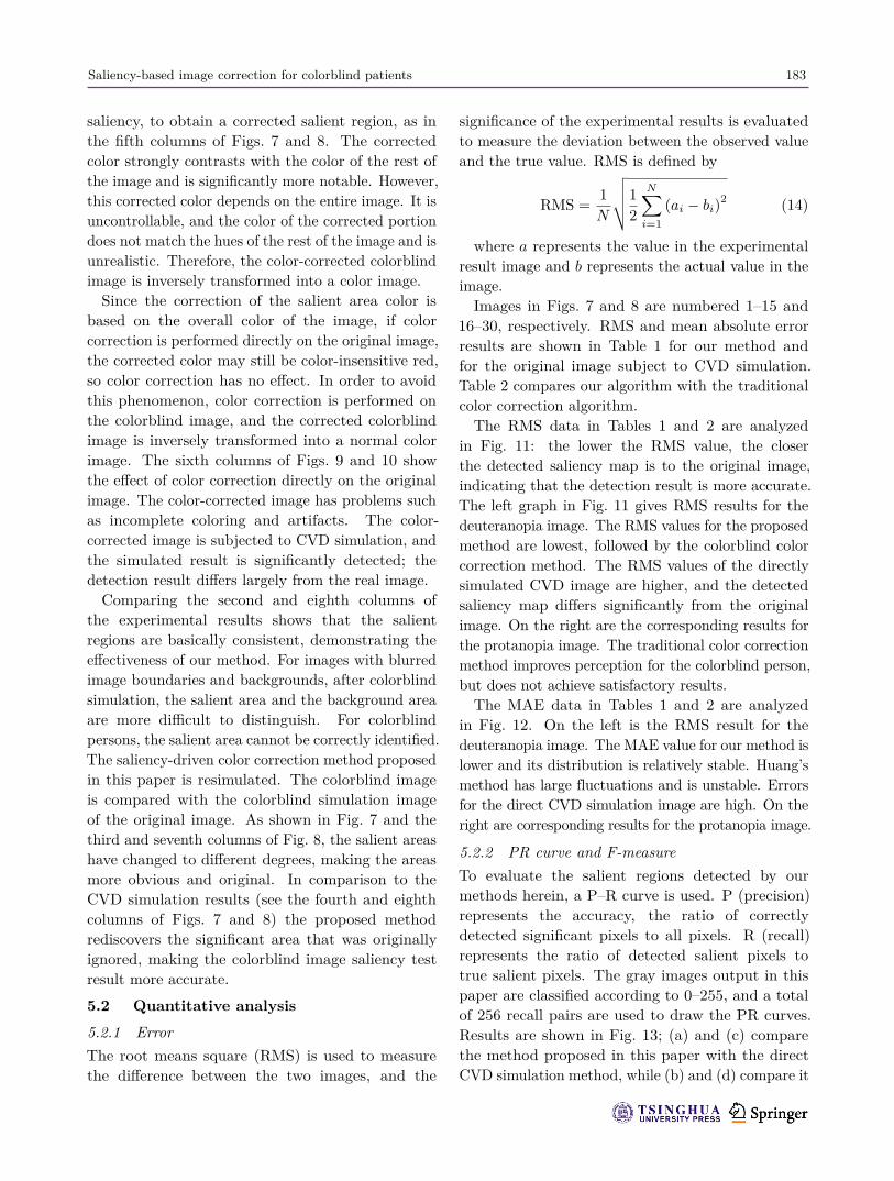
5.2 Quantitative analysis5.2.1 ErrorThe root means square (RMS) is used to measurethe difference between the two images, and the
significance of the experimental results is evaluatedto measure the deviation between the observed valueand the true value. RMS is defined by
RMS =1N
√√√√12
N∑i=1
(ai − bi)2 (14)
where a represents the value in the experimentalresult image and b represents the actual value in theimage.Images in Figs. 7 and 8 are numbered 1–15 and
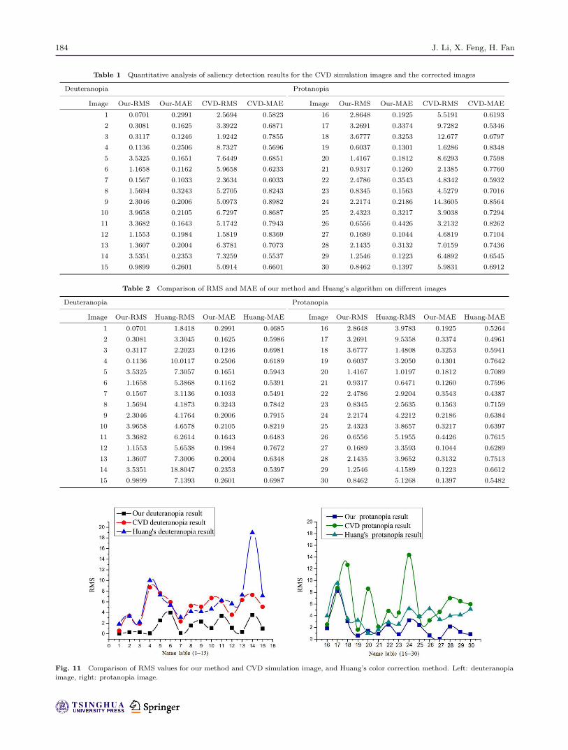
16–30, respectively. RMS and mean absolute errorresults are shown in Table 1 for our method andfor the original image subject to CVD simulation.Table 2 compares our algorithm with the traditionalcolor correction algorithm.The RMS data in Tables 1 and 2 are analyzed
in Fig. 11: the lower the RMS value, the closerthe detected saliency map is to the original image,indicating that the detection result is more accurate.The left graph in Fig. 11 gives RMS results for thedeuteranopia image. The RMS values for the proposedmethod are lowest, followed by the colorblind colorcorrection method. The RMS values of the directlysimulated CVD image are higher, and the detectedsaliency map differs significantly from the originalimage. On the right are the corresponding results forthe protanopia image. The traditional color correctionmethod improves perception for the colorblind person,but does not achieve satisfactory results.The MAE data in Tables 1 and 2 are analyzed
in Fig. 12. On the left is the RMS result for thedeuteranopia image. The MAE value for our method islower and its distribution is relatively stable. Huang’smethod has large fluctuations and is unstable. Errorsfor the direct CVD simulation image are high. On theright are corresponding results for the protanopia image.
5.2.2 PR curve and F-measureTo evaluate the salient regions detected by ourmethods herein, a P–R curve is used. P (precision)represents the accuracy, the ratio of correctlydetected significant pixels to all pixels. R (recall)represents the ratio of detected salient pixels totrue salient pixels. The gray images output in thispaper are classified according to 0–255, and a totalof 256 recall pairs are used to draw the PR curves.Results are shown in Fig. 13; (a) and (c) comparethe method proposed in this paper with the directCVD simulation method, while (b) and (d) compare it
184 J. Li, X. Feng, H. Fan
Table 1 Quantitative analysis of saliency detection results for the CVD simulation images and the corrected images
Deuteranopia Protanopia
Image Our-RMS Our-MAE CVD-RMS CVD-MAE Image Our-RMS Our-MAE CVD-RMS CVD-MAE1 0.0701 0.2991 2.5694 0.5823 16 2.8648 0.1925 5.5191 0.61932 0.3081 0.1625 3.3922 0.6871 17 3.2691 0.3374 9.7282 0.53463 0.3117 0.1246 1.9242 0.7855 18 3.6777 0.3253 12.677 0.67974 0.1136 0.2506 8.7327 0.5696 19 0.6037 0.1301 1.6286 0.83485 3.5325 0.1651 7.6449 0.6851 20 1.4167 0.1812 8.6293 0.75986 1.1658 0.1162 5.9658 0.6233 21 0.9317 0.1260 2.1385 0.77607 0.1567 0.1033 2.3634 0.6033 22 2.4786 0.3543 4.8342 0.59328 1.5694 0.3243 5.2705 0.8243 23 0.8345 0.1563 4.5279 0.70169 2.3046 0.2006 5.0973 0.8982 24 2.2174 0.2186 14.3605 0.8564
10 3.9658 0.2105 6.7297 0.8687 25 2.4323 0.3217 3.9038 0.729411 3.3682 0.1643 5.1742 0.7943 26 0.6556 0.4426 3.2132 0.826212 1.1553 0.1984 1.5819 0.8369 27 0.1689 0.1044 4.6819 0.710413 1.3607 0.2004 6.3781 0.7073 28 2.1435 0.3132 7.0159 0.743614 3.5351 0.2353 7.3259 0.5537 29 1.2546 0.1223 6.4892 0.654515 0.9899 0.2601 5.0914 0.6601 30 0.8462 0.1397 5.9831 0.6912
Table 2 Comparison of RMS and MAE of our method and Huang’s algorithm on different images
Deuteranopia Protanopia
Image Our-RMS Huang-RMS Our-MAE Huang-MAE Image Our-RMS Huang-RMS Our-MAE Huang-MAE1 0.0701 1.8418 0.2991 0.4685 16 2.8648 3.9783 0.1925 0.52642 0.3081 3.3045 0.1625 0.5986 17 3.2691 9.5358 0.3374 0.49613 0.3117 2.2023 0.1246 0.6981 18 3.6777 1.4808 0.3253 0.59414 0.1136 10.0117 0.2506 0.6189 19 0.6037 3.2050 0.1301 0.76425 3.5325 7.3057 0.1651 0.5943 20 1.4167 1.0197 0.1812 0.70896 1.1658 5.3868 0.1162 0.5391 21 0.9317 0.6471 0.1260 0.75967 0.1567 3.1136 0.1033 0.5491 22 2.4786 2.9204 0.3543 0.43878 1.5694 4.1873 0.3243 0.7842 23 0.8345 2.5635 0.1563 0.71599 2.3046 4.1764 0.2006 0.7915 24 2.2174 4.2212 0.2186 0.6384
10 3.9658 4.6578 0.2105 0.8219 25 2.4323 3.8657 0.3217 0.639711 3.3682 6.2614 0.1643 0.6483 26 0.6556 5.1955 0.4426 0.761512 1.1553 5.6538 0.1984 0.7672 27 0.1689 3.3593 0.1044 0.628913 1.3607 7.3006 0.2004 0.6348 28 2.1435 3.9652 0.3132 0.751314 3.5351 18.8047 0.2353 0.5397 29 1.2546 4.1589 0.1223 0.661215 0.9899 7.1393 0.2601 0.6987 30 0.8462 5.1268 0.1397 0.5482
Fig. 11 Comparison of RMS values for our method and CVD simulation image, and Huang’s color correction method. Left: deuteranopiaimage, right: protanopia image.

Saliency-based image correction for colorblind patients 185
Fig. 12 Comparison of MAE values for our method, CVD simulation image, and Huang’s color correction method. Left: deuteranopia image,right: protanopia image.
Fig. 13 Comparison of PR curves for different images. (a, c) compare our method with a direct CVD simulation image. (b, d) compare ourmethod with Huang’s color correction method. (a, b) Green blind images. (c, d) Red blind images.
with the Huang’s color correction algorithm. It isclear that for a given recall rate, our method is moreaccurate than direct detection of colorblind images,and than Huang’s algorithm.
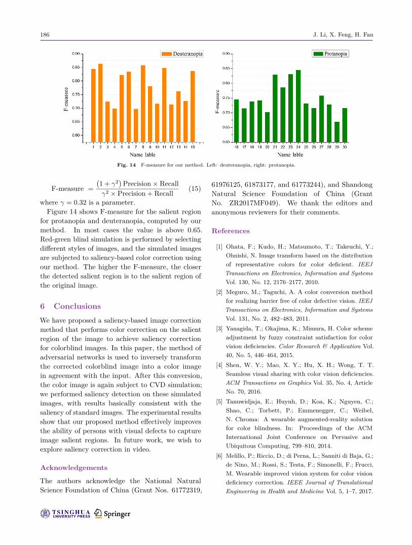
In most cases, the PR curve does not provide acomprehensive assessment of the significance of theimage. Therefore, this paper uses the F-measure forcomprehensive evaluation, defined as
186 J. Li, X. Feng, H. Fan
Fig. 14 F-measure for our method. Left: deuteranopia, right: protanopia.
F-measure =(1 + γ2)
Precision × Recallγ2 × Precision + Recall
(15)
where γ = 0.32 is a parameter.Figure 14 shows F-measure for the salient region
for protanopia and deuteranopia, computed by ourmethod. In most cases the value is above 0.65.Red-green blind simulation is performed by selectingdifferent styles of images, and the simulated imagesare subjected to saliency-based color correction usingour method. The higher the F-measure, the closerthe detected salient region is to the salient region ofthe original image.
6 ConclusionsWe have proposed a saliency-based image correctionmethod that performs color correction on the salientregion of the image to achieve saliency correctionfor colorblind images. In this paper, the method ofadversarial networks is used to inversely transformthe corrected colorblind image into a color imagein agreement with the input. After this conversion,the color image is again subject to CVD simulation;we performed saliency detection on these simulatedimages, with results basically consistent with thesaliency of standard images. The experimental resultsshow that our proposed method effectively improvesthe ability of persons with visual defects to captureimage salient regions. In future work, we wish toexplore saliency correction in video.
Acknowledgements
The authors acknowledge the National NaturalScience Foundation of China (Grant Nos. 61772319,
61976125, 61873177, and 61773244), and ShandongNatural Science Foundation of China (GrantNo. ZR2017MF049). We thank the editors andanonymous reviewers for their comments.
References
[1] Ohata, F.; Kudo, H.; Matsumoto, T.; Takeuchi, Y.;Ohnishi, N. Image transform based on the distributionof representative colors for color deficient. IEEJTransactions on Electronics, Information and SystemsVol. 130, No. 12, 2176–2177, 2010.
[2] Meguro, M.; Taguchi, A. A color conversion methodfor realizing barrier free of color defective vision. IEEJTransactions on Electronics, Information and SystemsVol. 131, No. 2, 482–483, 2011.
[3] Yanagida, T.; Okajima, K.; Mimura, H. Color schemeadjustment by fuzzy constraint satisfaction for colorvision deficiencies. Color Research & Application Vol.40, No. 5, 446–464, 2015.
[4] Shen, W. Y.; Mao, X. Y.; Hu, X. H.; Wong, T. T.Seamless visual sharing with color vision deficiencies.ACM Transactions on Graphics Vol. 35, No. 4, ArticleNo. 70, 2016.
[5] Tanuwidjaja, E.; Huynh, D.; Koa, K.; Nguyen, C.;Shao, C.; Torbett, P.; Emmenegger, C.; Weibel,N. Chroma: A wearable augmented-reality solutionfor color blindness. In: Proceedings of the ACMInternational Joint Conference on Pervasive andUbiquitous Computing, 799–810, 2014.
[6] Melillo, P.; Riccio, D.; di Perna, L.; Sanniti di Baja, G.;de Nino, M.; Rossi, S.; Testa, F.; Simonelli, F.; Frucci,M. Wearable improved vision system for color visiondeficiency correction. IEEE Journal of TranslationalEngineering in Health and Medicine Vol. 5, 1–7, 2017.

Saliency-based image correction for colorblind patients 187
[7] Weale, R. Defective colour vision: Fundamentals,diagnosis and management. British Journal ofOphthalmology Vol. 70, No. 2, 159, 1986.
[8] Rosenstock, H. B.; Swick, D. A. Color discriminationfor the color blind. Aerospace Medicine Vol. 45, No. 10,1194, 1974.
[9] Kessler, J. What can be done for the color blind?Annals of Ophthalmology Vol. 9, No. 4, 431–433, 1977.
[10] Subbian, V.; Ratcliff, J.; Meunier, J.; Korfhagen, J.;Beyette, F.; Shaw, G. Integration of new technology forresearch in the emergency department: Feasibility ofdeploying a robotic assessment tool for mild traumaticbrain injury evaluation. IEEE Journal of TranslationalEngineering in Health and Medicine Vol. 3, Article No.3200109, 2015.
[11] Nakayama, K. Assist device in color discriminationusing Heilmeier type guest-host liquid crystalfor red-green color vision defect. Electronics andCommunications in Japan Vol. 102, No. 8, 17–24, 2019.
[12] Hunt, R. W. G. Colour standards and calculations. In:The Reproduction of Colour. Kriss, M. A.; Hunt, R.John Wiley & Sons, Ltd, 92–125, 2005.
[13] Nathans, J.; Thomas, D.; Hogness, D. Moleculargenetics of human color vision: The genes encodingblue, green, and red pigments. Science Vol. 232, No.4747, 193–202, 1986.
[14] Wong, B. Points of view: Color blindness. NatureMethods Vol. 8, No. 6, 441, 2011.
[15] Scoles, D.; Sulai, Y. N.; Dubra, A. In vivo dark-fieldimaging of the retinal pigment epithelium cell mosaic.Biomedical Optics Express Vol. 4, No. 9, 1710, 2013.
[16] Brettel, H.; Vienot, F.; Mollon, J. D. Computerizedsimulation of color appearance for dichromats. Journalof the Optical Society of America A Vol. 14, No. 10,2647, 1997.
[17] Meyer, G. W.; Greenberg, D. P. Color-defectivevision and computer graphics displays. IEEE ComputerGraphics and Applications Vol. 8, No. 5, 28–40, 1988.
[18] MacHado, G. M.; Oliveira, M. M.; Fernandes, L. Aphysiologically-based model for simulation of colorvision deficiency. IEEE Transactions on Visualizationand Computer Graphics Vol. 15, No. 6, 1291–1298,2009.
[19] Chen, C. S.; Wu, S. Y.; Huang, J. B. Enhancingcolor representation for the color vision impaired. In:Proceedings of ECCV Workshop on Computer VisionApplications for the Visually Impaired, 2008.
[20] Okajima, K.; Kanbe, S. A real-time color simulationof dichromats. Technical Report of the IEICE, 107:107110, 2007.
[21] Flatla, D. R.; Gutwin, C. Individual models ofcolor differentiation to improve interpretability ofinformation visualization. In: Proceedings of theSIGCHI Conference on Human Factors in ComputingSystems, 2563–2572, 2010.
[22] Kuhn, G. R.; Oliveira, M. M.; Fernandes, L. An efficientnaturalness-preserving image-recoloring method fordichromats. IEEE Transactions on Visualization andComputer Graphics Vol. 14, No. 6, 1747–1754, 2008.
[23] Jiang, H. Z.; Wang, J. D.; Yuan, Z. J.; Wu, Y.;Zheng, N. N.; Li, S. P. Salient object detection: Adiscriminative regional feature integration approach.In: Proceedings of the IEEE Conference on ComputerVision and Pattern Recognition, 2083–2090, 2013.
[24] Peng, H. W.; Li, B.; Ling, H. B.; Hu, W. M.; Xiong,W. H.; Maybank, S. J. Salient object detection viastructured matrix decomposition. IEEE Transactionson Pattern Analysis and Machine Intelligence Vol. 39,No. 4, 818–832, 2017.
[25] Cong, R. M.; Lei, J. J.; Fu, H. Z.; Huang, Q. M.; Cao,X. C.; Hou, C. P. Co-saliency detection for RGBDimages based on multi-constraint feature matching andcross label propagation. IEEE Transactions on ImageProcessing Vol. 27, No. 2, 568–579, 2018.
[26] Cheng, M. M.; Mitra, N. J.; Huang, X. L.; Torr, P.H. S.; Hu, S. M. Global contrast based salient regiondetection. IEEE Transactions on Pattern Analysis andMachine Intelligence Vol. 37, No. 3, 569–582, 2015.
[27] Wang, W. G.; Shen, J. B.; Shao, L.; Porikli,F. Correspondence driven saliency transfer. IEEETransactions on Image Processing Vol. 25, No. 11, 5025–5034, 2016.
[28] Borji, A.; Cheng, M. M.; Jiang, H. Z.; Li, J. Salientobject detection: A benchmark. IEEE Transactions onImage Processing Vol. 24, No. 12, 5706–5722, 2015.
[29] Wang, L. J.; Lu, H. C.; Ruan, X.; Yang, M. H. Deepnetworks for saliency detection via local estimation andglobal search. In: Proceedings of the IEEE Conferenceon Computer Vision and Pattern Recognition, 3183–3192, 2015.
[30] Zhao, R.; Ouyang, W. L.; Li, H. S.; Wang, X. G.Saliency detection by multi-context deep learning. In:Proceedings of the IEEE Conference on ComputerVision and Pattern Recognition, 1265–1274, 2015.
[31] Han, J. W.; Zhang, D. W.; Hu, X. T.; Guo, L.;Ren, J. C.; Wu, F. Background prior-based salientobject detection via deep reconstruction residual.IEEE Transactions on Circuits and Systems for VideoTechnology Vol. 25, No. 8, 1309–1321, 2015.

188 J. Li, X. Feng, H. Fan
[32] Huang, X.; Shen, C. Y.; Boix, X.; Zhao, Q. SALICON:Reducing the semantic gap in saliency prediction byadapting deep neural networks. In: Proceedings of theIEEE International Conference on Computer Vision,262–270, 2015.
[33] Chen, T. S.; Lin, L.; Liu, L. B.; Luo, X. N.; Li, X. L.DISC: Deep image saliency computing via progressiverepresentation learning. IEEE Transactions on NeuralNetworks and Learning Systems Vol. 27, No. 6, 1135–1149, 2016.
[34] Zhang, J. M.; Sclaroff, S.; Lin, Z.; Shen, X. H.; Price,B.; Mech, R. Unconstrained salient object detectionvia proposal subset optimization. In: Proceedings ofthe IEEE Conference on Computer Vision and PatternRecognition, 5733–5742, 2016.
[35] Li, G. B.; Xie, Y.; Lin, L.; Yu, Y. Z. Instance-levelsalient object segmentation. In: Proceedings of theIEEE Conference on Computer Vision and PatternRecognition, 2386–2395, 2017.
[36] Wang, W. G.; Shen, J. B.; Xie, J. W.; Cheng, M.M.; Ling, H. B.; Borji, A. Revisiting video saliencyprediction in the deep learning era. IEEE Transactionson Pattern Analysis and Machine Intelligence DOI:10.1109/TPAMI.2019.2924417, 2019.
[37] Wang, W. G.; Shen, J. B.; Yang, R. G.; Porikli,F. Saliency-aware video object segmentation. IEEETransactions on Pattern Analysis and MachineIntelligence Vol. 40, No. 1, 20–33, 2018.
[38] Wei, Y. C.; Feng, J. S.; Liang, X. D.; Cheng, M.M.; Zhao, Y.; Yan, S. C. Object region miningwith adversarial erasing: A simple classification tosemantic segmentation approach. In: Proceedings ofthe IEEE Conference on Computer Vision and PatternRecognition, 1568–1576, 2017.
[39] Wei, Y. C.; Liang, X. D.; Chen, Y. P.; Shen, X. H.;Cheng, M. M.; Feng, J. S.; Zhao, Y.; Yan, S. STC:A simple to complex framework for weakly-supervisedsemantic segmentation. IEEE Transactions on PatternAnalysis and Machine Intelligence Vol. 39, No. 11, 2314–2320, 2017.
[40] Wang, W. G.; Shen, J. B.; Ling, H. B. A deep networksolution for attention and aesthetics aware photocropping. IEEE Transactions on Pattern Analysis andMachine Intelligence Vol. 41, No. 7, 1531–1544, 2019.
[41] Sun, J.; Ling, H. B. Scale and object aware imageretargeting for thumbnail browsing. In: Proceedingsof the International Conference on Computer Vision,1511–1518, 2011.
[42] Zhou, L.; Yang, Z. H.; Zhou, Z. T.; Hu, D. W. Salientregion detection using diffusion process on a two-layersparse graph. IEEE Transactions on Image ProcessingVol. 26, No. 12, 5882–5894, 2017.
[43] Mateescu, V. A.; Bajic, I. V. Visual attentionretargeting. IEEE MultiMedia Vol. 23, No. 1, 82–91,2016.
[44] Nguyen, T. V.; Ni, B.; Liu, H.; Xia, W.; Luo, J.;Kankanhalli, M.; Yan, S. Image re-attentionizing. IEEETransactions on Multimedia Vol. 15, No. 8, 1910–1919,2013.
[45] Mateescu, V. A.; Bajic, I. V. Attention retargetingby color manipulation in images. In: Proceedings ofthe 1st International Workshop on Perception InspiredVideo Processing, 15–20, 2014.
[46] Mendez, E.; Feiner, S.; Schmalstieg, D. Focus andcontext in mixed reality by modulating first ordersalient features. In: Smart Graphics. Lecture Notes inComputer Science, Vol. 6133. Taylor, R.; Boulanger, P.;Kruger, A.; Olivier, P. Eds. Springer Berlin Heidelberg,232–243, 2010.
[47] Lu, S. P.; Dauphin, G.; Lafruit, G.; Munteanu, A.Color retargeting: Interactive time-varying color imagecomposition from time-lapse sequences. ComputationalVisual Media Vol. 1, No. 4, 321–330, 2015.
[48] Fried, O.; Shechtman, E.; Goldman, D. B.; Finkelstein,A. Finding distractors in images. In: Proceedings ofthe IEEE Conference on Computer Vision and PatternRecognition, 1703–1712, 2015.
[49] Su, S. L.; Durand, F.; Agrawala, M. De-emphasis ofdistracting image regions using texture power maps.In: Proceedings of the 2nd Symposium on AppliedPerception in Graphics and Visualization, 164, 2005.
[50] Li, J. J.; Li, G. H.; Fan, H. Image dehazing usingresidual-based deep CNN. IEEE Access Vol. 6, 26831–26842, 2018.
[51] Mechrez, R.; Shechtman, E.; Zelnik-Manor, L. Saliencydriven image manipulation. Machine Vision andApplications Vol. 30, No. 2, 189–202, 2019.
[52] Huang, J. B.; Chen, C. S.; Jen, T. C.; Wang, S. J.Image recolorization for the colorblind. In: Proceedingsof the IEEE International Conference on Acoustics,Speech and Signal Processing, 1161–1164, 2009.
[53] Lin, H. Y.; Chen, L. Q.; Wang, M. L. Improvingdiscrimination in color vision deficiency by image re-coloring. Sensors Vol. 19, No. 10, 2250, 2019.
[54] Sundaram, N.; Brox, T.; Keutzer, K. Dense pointtrajectories by GPU-accelerated large displacementoptical flow. In: Computer Vision – ECCV 2010.Lecture Notes in Computer Science, Vol. 6311.Daniilidis, K.; Maragos, P.; Paragios, N. Eds. SpringerBerlin Heidelberg, 438–451, 2010.
[55] Yang, C.; Zhang, L. H.; Lu, H. C.; Ruan, X.; Yang, M.H. Saliency detection via graph-based manifold ranking.In: Proceedings of the IEEE Conference on ComputerVision and Pattern Recognition, 3166–3173, 2013.

Saliency-based image correction for colorblind patients 189
[56] Zhang, S. Y.; Liang, R. Z.; Wang, M. ShadowGAN:Shadow synthesis for virtual objects with conditionaladversarial networks. Computational Visual Media Vol.5, No. 1, 105–115, 2019.
Jinjiang Li received his B.S. andM.S. degrees in computer science fromTaiyuan University of Technology,Taiyuan, China, in 2001 and 2004,respectively, his Ph.D. degree incomputer science from ShandongUniversity, Jinan, China, in 2010. From2004 to 2006, he was an assistant
research fellow at the Institute of Computer Science andTechnology of Peking University, Beijing, China. From2012 to 2014, he was a post-doctoral fellow at TsinghuaUniversity, Beijing, China. He is currently a professor atthe School of Computer Science and Technology, ShandongTechnology and Business University. His research interestsinclude image processing, computer graphics, computervision, and machine learning.
Xiaomei Feng received her B.S. degreein School of Computer Science andTechnology from Qilu Normal University,Jinan, China in 2018. Currently, sheis an M.S. degree candidate in theSchool of Information and ElectronicEngineering, Shandong Technology andBusiness University, Yantai, China. Her
research interests include computer graphics, computervision, and image processing.
Hui Fan received his B.S. degreein computer science from ShandongUniversity, Jinan, China, in 1984. Hereceived his Ph.D. degree in computerscience from Taiyuan University ofTechnology, Taiyuan, China, in 2007.From 1984 to 2001, he was a professor atthe Computer Department of Taiyuan
University Technology. He is currently a professor atShandong Technology and Business University. His researchinterests include computer aided geometric design, computergraphics, information visualization, virtual reality, and imageprocessing.
Open Access This article is licensed under a CreativeCommons Attribution 4.0 International License, whichpermits use, sharing, adaptation, distribution and reproduc-tion in any medium or format, as long as you give appropriatecredit to the original author(s) and the source, provide a linkto the Creative Commons licence, and indicate if changeswere made.
The images or other third party material in this article areincluded in the article’s Creative Commons licence, unlessindicated otherwise in a credit line to the material. If materialis not included in the article’s Creative Commons licence andyour intended use is not permitted by statutory regulation orexceeds the permitted use, you will need to obtain permissiondirectly from the copyright holder.
To view a copy of this licence, visit http://creativecommons.org/licenses/by/4.0/.
Other papers from this open access journal are availablefree of charge from http://www.springer.com/journal/41095.To submit a manuscript, please go to https://www.editorialmanager.com/cvmj.
Related Documents


![Pb Colorblind 0[1]](https://static.cupdf.com/doc/110x72/577ccf1b1a28ab9e788ee4c0/pb-colorblind-01.jpg)