123 SPRINGER BRIEFS IN ELECTRICAL AND COMPUTER ENGINEERING Saleh Faruque Radio Frequency Multiple Access Techniques Made Easy

Welcome message from author
This document is posted to help you gain knowledge. Please leave a comment to let me know what you think about it! Share it to your friends and learn new things together.
Transcript
123
S P R I N G E R B R I E F S I N E L E C T R I C A L A N D CO M P U T E R E N G I N E E R I N G
Saleh Faruque
Radio Frequency Multiple Access Techniques Made Easy

SpringerBriefs in Electrical and ComputerEngineering

More information about this series at http://www.springer.com/series/10059

Saleh Faruque
Radio Frequency MultipleAccess Techniques MadeEasy

Saleh FaruqueDepartment of Electrical EngineeringUniversity of North DakotaGrand Forks, ND, USA
ISSN 2191-8112 ISSN 2191-8120 (electronic)SpringerBriefs in Electrical and Computer EngineeringISBN 978-3-319-91649-1 ISBN 978-3-319-91651-4 (eBook)https://doi.org/10.1007/978-3-319-91651-4
Library of Congress Control Number: 2018948162
© The Author(s), under exclusive license to Springer Nature Switzerland AG. 2019This work is subject to copyright. All rights are reserved by the Publisher, whether the whole or part of thematerial is concerned, specifically the rights of translation, reprinting, reuse of illustrations, recitation,broadcasting, reproduction on microfilms or in any other physical way, and transmission or informationstorage and retrieval, electronic adaptation, computer software, or by similar or dissimilar methodologynow known or hereafter developed.The use of general descriptive names, registered names, trademarks, service marks, etc. in this publicationdoes not imply, even in the absence of a specific statement, that such names are exempt from the relevantprotective laws and regulations and therefore free for general use.The publisher, the authors, and the editors are safe to assume that the advice and information in thisbook are believed to be true and accurate at the date of publication. Neither the publisher nor the authors orthe editors give a warranty, express or implied, with respect to the material contained herein or for anyerrors or omissions that may have been made. The publisher remains neutral with regard to jurisdictionalclaims in published maps and institutional affiliations.
Printed on acid-free paper
This Springer imprint is published by the registered company Springer Nature Switzerland AGThe registered company address is: Gewerbestrasse 11, 6330 Cham, Switzerland

Preface
In telecommunications, multiple access techniques enable many users to share thesame spectrum in the frequency domain, time domain, code domain, or phasedomain. It begins with a frequency band, allocated by the Federal CommunicationsCommission (FCC). FCC provides licenses to operate wireless communicationsystems over given bands of frequencies. These bands of frequencies are furtherdivided into smaller bands (channels) and reused to provide services to other users.This is governed by the International Telecommunication Union (ITU). ITU gener-ates standards such as FDMA, TDMA, CDMA, OFDMA, etc. for wirelesscommunications.
As the size and speed of digital data networks continue to expand, bandwidthefficiency becomes increasingly important. This is especially true for broadbandcommunications, where the choice of modulation schemes is important, keeping inmind the available bandwidth resources allocated by FCC. With these constraints inmind, this book will present a comprehensive overview of multiple access tech-niques used in the cellular industry. Numerous illustrations will be used to bringstudents up-to-date in key concepts, underlying principles, and practical applicationsof multiple access techniques so that they can readily put them into work in theindustry.
The list of topics under consideration is presented below:
• Introduction• Mode of Operation: FDD, TDD• FDMA Technique• TDMA Technique• CDMA Technique• OFDMA Technique• Conclusions
This text has been primarily designed for electrical engineering students in thearea of telecommunications. However, engineers and designers working in the area
v
of wireless communications would also find this text useful. It is assumed that thereader is familiar with the general theory of telecommunications.
In closing, I would like to say a few words about how this book was conceived. Itcame out of my long industrial and academic career. During my teaching tenure atthe University of North Dakota (UND), I developed a number of graduate-levelelective courses in the area of telecommunications, which combine theory andpractice. This book is a collection of my courseware, research activities, andhands-on experience in wireless communications.
I am grateful to the UND and the School for the Blind, North Dakota, foraffording me this opportunity. This book would never have seen the light of dayhad UND and the State of North Dakota not provided me with the technology to doso. My heartfelt salute goes out to the dedicated developers of these technologies,who have enabled me and others visually impaired to work comfortably.
I would like to thank my beloved wife, Yasmin, an English literature buff and awriter herself, for being by my side throughout the writing of this book and forpatiently proofreading it and to my darling son, Shams, an electrical engineerhimself, for providing technical support in formulation, simulation, and experimen-tation when I needed it. For this, he deserves my heartfelt thanks.
In spite of all this support, there may still be some errors in this book. I hope thatmy readers forgive me for them. I shall be amply rewarded if they still find this bookuseful.
Grand Forks, ND, USA Saleh Faruque
vi Preface

Contents
1 Introduction . . . . . . . . . . . . . . . . . . . . . . . . . . . . . . . . . . . . . . . . . . . . 11.1 Introduction to Multiple Access Techniques . . . . . . . . . . . . . . . . . . 11.2 Mode of Operation . . . . . . . . . . . . . . . . . . . . . . . . . . . . . . . . . . . . 3
1.2.1 Background . . . . . . . . . . . . . . . . . . . . . . . . . . . . . . . . . . . . 31.2.2 Frequency Division Duplex (FDD) . . . . . . . . . . . . . . . . . . . 41.2.3 Time Division Duplex (TDD) . . . . . . . . . . . . . . . . . . . . . . . 5
1.3 FDMA Technique . . . . . . . . . . . . . . . . . . . . . . . . . . . . . . . . . . . . . 61.4 TDMA Technique . . . . . . . . . . . . . . . . . . . . . . . . . . . . . . . . . . . . 71.5 CDMA Technique . . . . . . . . . . . . . . . . . . . . . . . . . . . . . . . . . . . . 81.6 OFDMA Technique . . . . . . . . . . . . . . . . . . . . . . . . . . . . . . . . . . . 111.7 Conclusions . . . . . . . . . . . . . . . . . . . . . . . . . . . . . . . . . . . . . . . . . 13References . . . . . . . . . . . . . . . . . . . . . . . . . . . . . . . . . . . . . . . . . . . . . . 13
2 Simplex, Duplex, FDD, and TDD . . . . . . . . . . . . . . . . . . . . . . . . . . . . 152.1 Introduction . . . . . . . . . . . . . . . . . . . . . . . . . . . . . . . . . . . . . . . . . 15
2.1.1 Simplex . . . . . . . . . . . . . . . . . . . . . . . . . . . . . . . . . . . . . . 152.1.2 Half-Duplex . . . . . . . . . . . . . . . . . . . . . . . . . . . . . . . . . . . 162.1.3 Full Duplex . . . . . . . . . . . . . . . . . . . . . . . . . . . . . . . . . . . . 16
2.2 FDD and TDD Schemes . . . . . . . . . . . . . . . . . . . . . . . . . . . . . . . . 172.2.1 Background . . . . . . . . . . . . . . . . . . . . . . . . . . . . . . . . . . . . 172.2.2 Frequency Division Duplex (FDD) . . . . . . . . . . . . . . . . . . . 172.2.3 Time Division Duplex (TDD) . . . . . . . . . . . . . . . . . . . . . . . 18
2.3 Conclusions . . . . . . . . . . . . . . . . . . . . . . . . . . . . . . . . . . . . . . . . . 20References . . . . . . . . . . . . . . . . . . . . . . . . . . . . . . . . . . . . . . . . . . . . . . 20
3 Frequency Division Multiple Access (FDMA) . . . . . . . . . . . . . . . . . . . 213.1 Introduction to FDMA . . . . . . . . . . . . . . . . . . . . . . . . . . . . . . . . 213.2 FDMA-FDD Technique . . . . . . . . . . . . . . . . . . . . . . . . . . . . . . . 223.3 FDMA-TDD Technique . . . . . . . . . . . . . . . . . . . . . . . . . . . . . . . 243.4 FDMA Cellular Telephoney . . . . . . . . . . . . . . . . . . . . . . . . . . . . 263.5 The Concept of Cell . . . . . . . . . . . . . . . . . . . . . . . . . . . . . . . . . . 28
vii
3.6 N ¼ 7 Cell Cluster . . . . . . . . . . . . . . . . . . . . . . . . . . . . . . . . . . . 283.7 N ¼ 3 Cell Cluster . . . . . . . . . . . . . . . . . . . . . . . . . . . . . . . . . . . 293.8 Sectorization . . . . . . . . . . . . . . . . . . . . . . . . . . . . . . . . . . . . . . . 293.9 Spectrum Management . . . . . . . . . . . . . . . . . . . . . . . . . . . . . . . . 30
3.9.1 Background . . . . . . . . . . . . . . . . . . . . . . . . . . . . . . . . . . . 303.9.2 The N ¼ 7 Frequency Planning . . . . . . . . . . . . . . . . . . . . . 303.9.3 N ¼ 3 Frequency Planning . . . . . . . . . . . . . . . . . . . . . . . . 31
3.10 Conclusions . . . . . . . . . . . . . . . . . . . . . . . . . . . . . . . . . . . . . . . . 32References . . . . . . . . . . . . . . . . . . . . . . . . . . . . . . . . . . . . . . . . . . . . . . 32
4 Time Division Multiple Access (TDMA) . . . . . . . . . . . . . . . . . . . . . . . 354.1 Introduction to TDMA . . . . . . . . . . . . . . . . . . . . . . . . . . . . . . . . . 354.2 TDMA Frame Structure . . . . . . . . . . . . . . . . . . . . . . . . . . . . . . . . 374.3 European GSM TDMA Cellular . . . . . . . . . . . . . . . . . . . . . . . . . . 39
4.3.1 GSM TDMA Schème . . . . . . . . . . . . . . . . . . . . . . . . . . . . 394.3.2 GSM TDMA Frame (4.615 ms) . . . . . . . . . . . . . . . . . . . . . 394.3.3 GSM Multi-frame . . . . . . . . . . . . . . . . . . . . . . . . . . . . . . . 404.3.4 GSM Superframe (6.12 s) . . . . . . . . . . . . . . . . . . . . . . . . . . 424.3.5 GSM Hyperframe . . . . . . . . . . . . . . . . . . . . . . . . . . . . . . . 42
4.4 Conclusions . . . . . . . . . . . . . . . . . . . . . . . . . . . . . . . . . . . . . . . . . 43References . . . . . . . . . . . . . . . . . . . . . . . . . . . . . . . . . . . . . . . . . . . . . . 42
5 Code Division Multiple Access (CDMA) . . . . . . . . . . . . . . . . . . . . . . . 455.1 Introduction to CDMA . . . . . . . . . . . . . . . . . . . . . . . . . . . . . . . . . 455.2 Spectrum of NRZ Data . . . . . . . . . . . . . . . . . . . . . . . . . . . . . . . . . 475.3 Spectrum Spreading . . . . . . . . . . . . . . . . . . . . . . . . . . . . . . . . . . . 48
5.3.1 Basic Concept . . . . . . . . . . . . . . . . . . . . . . . . . . . . . . . . . . 485.3.2 Energy Delivered . . . . . . . . . . . . . . . . . . . . . . . . . . . . . . . . 495.3.3 Process Gain . . . . . . . . . . . . . . . . . . . . . . . . . . . . . . . . . . . 50
5.4 A Tour of Orthogonal Codes . . . . . . . . . . . . . . . . . . . . . . . . . . . . . 515.4.1 Generation of Orthogonal Codes . . . . . . . . . . . . . . . . . . . . . 525.4.2 Bi-orthogonal Codes . . . . . . . . . . . . . . . . . . . . . . . . . . . . . 54
5.5 Orthogonal Codes for Data Spreading and De-spreading . . . . . . . . . 555.5.1 Spreading Bit 0 and De-spreading to Recover Bit 0 . . . . . . . 555.5.2 Spreading Bit 1 and De-spreading to Recover Bit 1 . . . . . . . 565.5.3 Multiuser CDMA . . . . . . . . . . . . . . . . . . . . . . . . . . . . . . . 565.5.4 Observations on Spreading and De-spreading . . . . . . . . . . . 57
5.6 Construction of CDMA Radio . . . . . . . . . . . . . . . . . . . . . . . . . . . . 585.6.1 Background . . . . . . . . . . . . . . . . . . . . . . . . . . . . . . . . . . . . 585.6.2 Binary Bit 0 Transmit/Receive Mechanism . . . . . . . . . . . . . 585.6.3 Binary Bit 1 Transmit/Receive Mechanism . . . . . . . . . . . . . 59
5.7 CDMA Capacity . . . . . . . . . . . . . . . . . . . . . . . . . . . . . . . . . . . . . . 605.8 Conclusions . . . . . . . . . . . . . . . . . . . . . . . . . . . . . . . . . . . . . . . . . 62References . . . . . . . . . . . . . . . . . . . . . . . . . . . . . . . . . . . . . . . . . . . . . . 62
viii Contents

6 Orthogonal Frequency Division Multiple Access (OFDMA) . . . . . . . . 636.1 Introduction to OFDMA . . . . . . . . . . . . . . . . . . . . . . . . . . . . . . . . 636.2 Spectral Response of Data Before Modulation . . . . . . . . . . . . . . . . 656.3 Spectral Response of Data After Modulation . . . . . . . . . . . . . . . . . 67
6.3.1 Spectral Response After BPSK Modulation . . . . . . . . . . . . . 676.3.2 Spectral Response After QPSK Modulation . . . . . . . . . . . . . 686.3.3 Spectral Response After 8PSK Modulation . . . . . . . . . . . . . 696.3.4 Spectral Response After 16PSK Modulation . . . . . . . . . . . . 70
6.4 Construction of OFDMA Channels . . . . . . . . . . . . . . . . . . . . . . . . 726.5 OFDMA-TDD Mode of Operation . . . . . . . . . . . . . . . . . . . . . . . . . 746.6 Conclusions . . . . . . . . . . . . . . . . . . . . . . . . . . . . . . . . . . . . . . . . . 76References . . . . . . . . . . . . . . . . . . . . . . . . . . . . . . . . . . . . . . . . . . . . . . 76
Contents ix
Chapter 1Introduction
Abstract Multiple access techniques enable many users to share the same spectrumin the frequency domain, time domain, code domain, or phase domain. It begins witha frequency band, allocated by FCC (Federal Communication Commission). FCCprovides licenses to operate wireless communication systems over given bands offrequencies. These bands of frequencies are finite and have to be further divided intosmaller bands (Channels) and reused to provide services to other users. This isgoverned by the International Telecommunication Union (ITU). ITU generatesstandards such as FDMA, TDMA, CDMA, OFDMA, etc. for wireless communica-tions. These standards along with numerous illustrations are presented to bring thestudents up-to-date in key concepts, underlying principles, and practical applicationsof multiple access techniques so that they can readily put them into work in thecellular industry.
1.1 Introduction to Multiple Access Techniques
Multiple access technique is well known in cellular communications [1–7]. Itenables many users to share the same spectrum in the frequency domain, timedomain, code domain, or phase domain. It begins with a frequency band, allocatedby FCC (Federal Communication Commission). FCC provides licenses to operatewireless communication systems over given bands of frequencies. These bands offrequencies are finite and have to be further divided into smaller bands (Channels)and reused to provide services to other users. This is governed by the InternationalTelecommunication Union (ITU). ITU generates standards such as FDMA, TDMA,CDMA, OFDMA, etc. for wireless communications. Figure 1.1 illustrates the basicconcept of various multiple access techniques currently in use.
In FDMA (frequency division multiple access) [1–3], a carrier frequency isassigned to a single user. In this scheme, the channel is occupied by a single userfor the entire duration of the call. FDMA is the multiple access technique used inAMPS (advanced mobile phone system), also known as the first-generation(1G) cellular communication system.
© The Author(s), under exclusive license to Springer Nature Switzerland AG. 2019S. Faruque, Radio Frequency Multiple Access Techniques Made Easy,SpringerBriefs in Electrical and Computer Engineering,https://doi.org/10.1007/978-3-319-91651-4_1
1

In TDMA (time division multiple access) [1–3], a carrier frequency is assigned tomultiple users. In this scheme, the channel is used by multiple users, one at a time asdepicted in Fig. 1.1 [4–8]. TDMA is the multiple access technique used in NorthAmerican TDMA and European GSM wireless standards. TDMA is also known asthe second-generation (2G) cellular communication system.
In CDMA (code division multiple access) [1–3], multiple users have access to thesame carrier frequency at the same time. CDMA is also known as spread spectrumtechnique. This is accomplished by spreading the data by means of orthogonalcodes. In CDMA, each user is assigned a unique orthogonal code, while each useruses the same carrier frequency. The use of orthogonal codes enables each user tocommunicate without interference. CDMA is used in IS95 standard.
OFDMA (orthogonal frequency division multiple access) [6, 7] is an extension ofFDMA, where each band is placed at the null of the adjacent band, so that adjacentbands are orthogonal to each other and do not interfere. OFDMA is the multipleaccess technique used in WiMAX (Worldwide Interoperability for MicrowaveAccess) and LTE (Long-Term Evolution) protocol. It may be noted that WiMAXis an IEEE 802.16 standard while LTE is a standard developed by the 3GPP group.Both standards are surprisingly similar and bandwidth efficient. OFDMA is used in4G cellular standard.
OFDMA
CDMA
TDMA
FDMA
Frequency
FCC Allocated Frequency Band
Frequency
Frequency
Frequency
Frequency
Fig. 1.1 Basic concept of multiple access techniques
2 1 Introduction

In any multiple access techniques, multiple users have access to the samespectrum, so that the occupied bandwidth does not exceed the FCC allocatedchannel. Furthermore, as the size and speed of digital data networks continue toexpand, bandwidth efficiency becomes increasingly important. This is especiallytrue for broadband communication, where the choice of modulation scheme isimportant keeping in mind the available bandwidth resources, allocated by FCC.With these constraints in mind, this book will present a comprehensive overview ofmultiple access techniques used in the cellular industry. The concept of frequencyreuse will be studied along with carrier to interference (C/I). The classical cell reuseplan will be studied next with examples of various frequency plans related to OMNIand Sectorization schemes. Numerous illustrations will be used to bring students upto date in key concepts, underlying principles, and practical applications of multipleaccess techniques so that they can readily put them into work in the industry.
1.2 Mode of Operation
1.2.1 Background
Cellular communication is a full duplex, or simply a duplex communication system.Duplex is referred to as a two-way communication, where two users can communi-cate with each other simultaneously. Figure 1.2 illustrates the basic concept of a fullduplex cellular communication system, currently in use all over the world.
According to the communication protocol, the cellular base station assigns acarrier frequency to the cell phone. Once the carrier frequency is assigned, the cellphone modulates the carrier frequency by means of voice, data, or video. It thenamplifies the modulated carrier frequency and sends it to the antenna for transmis-sion. Upon receiving, the cellular radio at the base station responds to the cell phoneby means of a similar communication protocol. The link is maintained in bothdirections, either in the frequency domain or in the time domain. This is governedby two basic mode of operations listed below:
• Frequency division duplex (FDD)• Time division duplex (TDD)
A brief description of these communication modes are presented below.
Fig. 1.2 Illustration of fullduplex wirelesscommunication
1.2 Mode of Operation 3
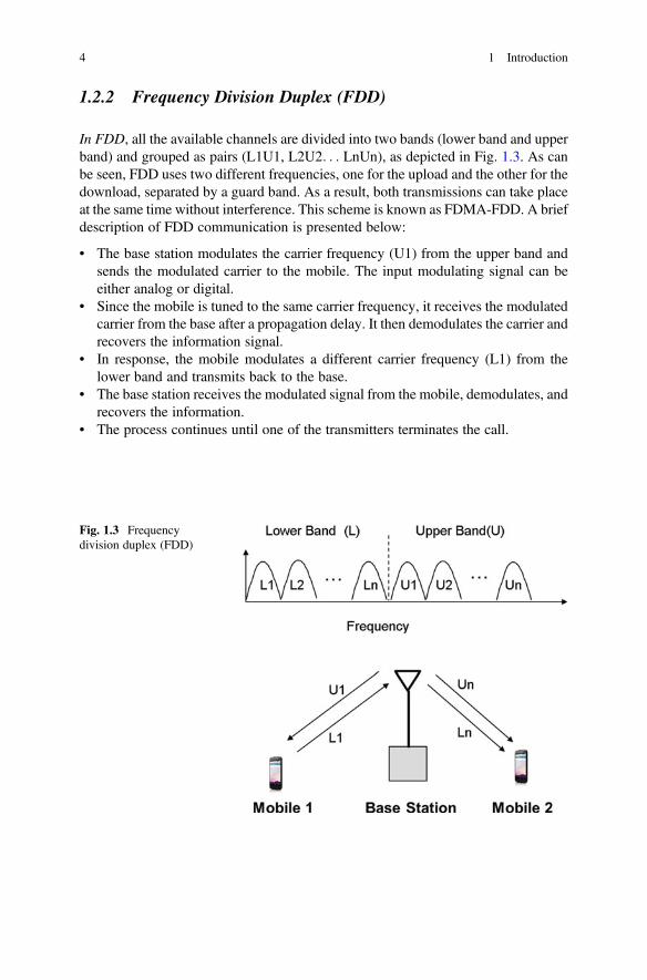
1.2.2 Frequency Division Duplex (FDD)
In FDD, all the available channels are divided into two bands (lower band and upperband) and grouped as pairs (L1U1, L2U2. . . LnUn), as depicted in Fig. 1.3. As canbe seen, FDD uses two different frequencies, one for the upload and the other for thedownload, separated by a guard band. As a result, both transmissions can take placeat the same time without interference. This scheme is known as FDMA-FDD. A briefdescription of FDD communication is presented below:
• The base station modulates the carrier frequency (U1) from the upper band andsends the modulated carrier to the mobile. The input modulating signal can beeither analog or digital.
• Since the mobile is tuned to the same carrier frequency, it receives the modulatedcarrier from the base after a propagation delay. It then demodulates the carrier andrecovers the information signal.
• In response, the mobile modulates a different carrier frequency (L1) from thelower band and transmits back to the base.
• The base station receives the modulated signal from the mobile, demodulates, andrecovers the information.
• The process continues until one of the transmitters terminates the call.
Fig. 1.3 Frequencydivision duplex (FDD)
4 1 Introduction

1.2.3 Time Division Duplex (TDD)
In TDD, a single frequency is time shared between the uplink and the downlink. Theduration of transmission in each direction is generally short, in the order of ms. Inthis scheme, when the mobile transmits, base station listens, and when the basestation transmits, mobile listens. This is accomplished by formatting the data into a“Frame,” where the frame is a collection of several time slots. Each time slot is apackage of data, representing digitized voice, digitized text, digitized video, andsynchronization bits (sync. bits). The sync bits are unique, which is used for framesynchronization. Details will be presented in subsequent chapters.
Figure 1.4 illustrates a typical frame and the TDD transmission scheme.According to TDD transmission protocol, both the base station and the mobile usethe same carrier frequency.
Figure 1.4 demonstrates a typical TDD scheme.The transmit/receive mechanism between the base station and mobile are as
follows:
• The base station modulates the carrier frequency by means of the digital infor-mation bits in frame F(B) and transmits to the mobile.
• Since the mobile is tuned to the same carrier frequency, it receives the frame F(B) after a propagation delay tp.
• Mobile synchronizes the frame using the sync bits and downloads the data.• After a guard time tg, mobile transmits its own frame F(M) to the base.
Frame (F)
Data(n-bit)
Round Trip
F(B)
Base
Mobile
tp tg
F(B)
F(M)
F(M)
Sync Word(k-bit)
a
b
Fig. 1.4 TDD framestructure. (a) Frame. (b)Frame transmission scheme
1.2 Mode of Operation 5
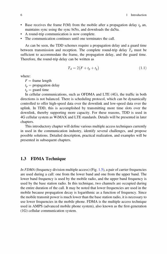
• Base receives the frame F(M) from the mobile after a propagation delay tp an,maintains sync using the sync bi5ts, and downloads the da5ta.
• A round-trip communication is now complete.• The communication continues until one terminates the call.
As can be seen, the TDD schemes require a propagation delay and a guard timebetween transmission and reception. The complete round-trip delay Td must besufficient to accommodate the frame, the propagation delay, and the guard time.Therefore, the round-trip delay can be written as
Td ¼ 2 F þ tp þ tg� � ð1:1Þ
where:F ¼ frame lengthtp ¼ propagation delaytg ¼ guard timeIn cellular communications, such as OFDMA and LTE (4G), the traffic in both
directions is not balanced. There is scheduling protocol, which can be dynamicallycontrolled to offer high-speed data over the downlink and low-speed data over theuplink. In TDD, this is accomplished by transmitting more time slots over thedownlink, thereby supporting more capacity. For these reasons, TDD is used in4G cellular system as WiMAX and LTE standards. Details will be presented in laterchapters.
This introductory chapter will define various multiple access techniques currentlyin used in the communication industry, identify several challenges, and proposepossible solutions. Detailed description, practical realization, and examples will bepresented in subsequent chapters.
1.3 FDMA Technique
In FDMA (frequency division multiple access) (Fig. 1.5), a pair of carrier frequenciesare used during a call: one from the lower band and one from the upper band. Thelower band frequency is used by the mobile radio, and the upper band frequency isused by the base station radio. In this technique, two channels are occupied duringthe entire duration of the call. It may be noted that lower frequencies are used in themobile because propagation decay is logarithmic as a function of frequency. Sincethe mobile transmit power is much lower than the base station radio, it is necessary touse lower frequencies in the mobile phone. FDMA is the multiple access techniqueused in AMPS (advanced mobile phone system), also known as the first-generation(1G) cellular communication system.
6 1 Introduction

1.4 TDMA Technique
TDMA (time division multiple access) is an extension of FDMA, where each FDMAchannel is time shared by multiple users, one at a time. In this technique, a pair ofFDMA channel is used during a call: one from the lower band and one from theupper band. The lower band frequency is time shared by several mobiles. The upperband frequency is also time shared synchronously by the base station radio. Bothchannels are occupied during the entire duration of the call.
The synchronization is achieved by means of a special frame structure, where theframe is a collection of time slots. Each time slot is assigned to a mobile. Figure 1.6shows the frame structure used in the North American 2G TDMA system. As shownin the figure, there are six time slots in the frame, where two time slots are assignedper user in sequence. This implies that, when one mobile has access to the channel,the other mobiles are idle. Therefore, TDMA synchronization is critical for datarecovery and collision avoidance.
TDMA has several advantages over FDMA:
• Increased channel capacity• Greater immunity to noise and interference• Secure communication• More flexibility and control
Moreover, it allows the existing FDMA standard to coexist in the same TDMAplatform, sharing the same RF spectrum. The detailed technology, adopted as theNorth American TDMA standard, will be presented in this book.
Input
CellPhone
OutputL1
L1 L2 Ln... ...
L1
U1
U1
U1
U2 Un
BaseStation
Input
Output
Upper Band(U)Lower Band (L)
Fig. 1.5 FDMA technique. A pair of channels are used during a call: one from the lower band andone from the upper band. The lower band frequency is used by the mobile radio, and the upper bandfrequency is used by the base station radio. Both channels are occupied during the entire duration ofthe call
1.4 TDMA Technique 7

1.5 CDMA Technique
In CDMA (code division multiple access), multiple users have access to the samecarrier frequency at the same time as depicted in Fig. 1.7. Here, a single carrierfrequency is used by several users, where each user is assigned a unique orthogonalcode.
The use of orthogonal codes enables each user to communicate without interfer-ence. CDMA is also known as spread spectrum technique. This is accomplished bymultiplying each information bit by means of an n-bit orthogonal code. Multiplica-tion in this process is referred to as exclusive OR (EXOR) operation. For example,when the binary bit 0 is multiplied by a 4 bit orthogonal code 0101, we write
0 EXOR 0101ð Þ ¼ 0101 ðx1:2Þ
Frame
BaseStation
CompositeData
Upper Band(U)Lower Band(L)
a
b
L1
L1
L1
CellPhone
BaseStation
Data In
Data Out
Data In
Data Out
L2 Ln U1
U1
U1
U2 Un• • •• • •
1 2 3 4 5 6
Fig. 1.6 TDMA technique. It is an extension of FDMA, where each FDMA channel is time sharedby several mobiles. Data transmission takes place over a frame
8 1 Introduction

This is the orthogonal code reproduced due to exclusive OR operation. Moreover,the bit rate is also multiplied by a factor of four, thereby spreading the spectrum by afactor of four as well.
Similarly, when the binary bit 1 is multiplied by the same orthogonal code, weobtain
1 EXOR 0101ð Þ ¼ 1010 ðx1:3ÞThis is the inverse of the orthogonal code. This code is also known as antipodal
code. The spectrum is also spread by a factor of four.Therefore, when an information bit is multiplied by an n-bit orthogonal code, the
spectrum is spread by a factor of n, enabling multiple users to share the samespectrum at the same time. For this reason a large bandwidth is assigned forCDMA radio. Details will be presented in this book as a separate chapter.
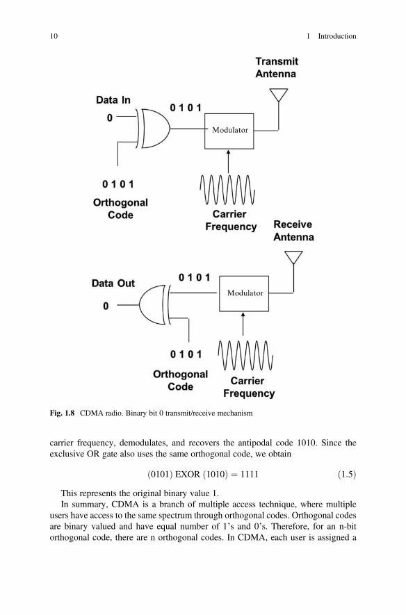
Let’s examine a CDMA radio based on 4-bit orthogonal code, where the codesequence is given by 0101. This is shown in Figs. 1.8 and 1.9. In Fig. 1.8, the binarybit 0 is multiplied by the 4 bit orthogonal code to reproduce the orthogonal code,which represents the information bit 0. Now, the modulator modulates the carrierfrequency by means of the orthogonal code and transmits through the antenna. Thereceiver intercepts the modulated carrier frequency, demodulates, and recovers theorthogonal code 0101. Since the exclusive OR gate also uses the same orthogonalcode, we obtain
0101ð Þ EXOR 0101ð Þ ¼ 0000 ðx1:4ÞThis represents the original binary value 0.Similarly, in Fig. 1.9, the binary bit 1 is multiplied by the same 4 bit orthogonal
code to generate the antipodal code 1010, which represents the information bit1. Now, the modulator modulates the carrier frequency by means of the antipodalcode and transmits through the antenna. The receiver intercepts the modulated
CDMA Frequency
Data Out
Data In
Data Out
Data In
BaseStation
CellPhone
Fig. 1.7 CDMA technique.A single frequency is usedmy multiple user
1.5 CDMA Technique 9
carrier frequency, demodulates, and recovers the antipodal code 1010. Since theexclusive OR gate also uses the same orthogonal code, we obtain
0101ð Þ EXOR 1010ð Þ ¼ 1111 ð1:5ÞThis represents the original binary value 1.In summary, CDMA is a branch of multiple access technique, where multiple
users have access to the same spectrum through orthogonal codes. Orthogonal codesare binary valued and have equal number of 1’s and 0’s. Therefore, for an n-bitorthogonal code, there are n orthogonal codes. In CDMA, each user is assigned a
Fig. 1.8 CDMA radio. Binary bit 0 transmit/receive mechanism
10 1 Introduction

unique orthogonal code. Yet, there is a limitation of using all the codes, which isrelated to channel capacity. We will address this issue in details in this book.
1.6 OFDMA Technique
OFDMA (orthogonal frequency division multiple access) is an extension of FDMA,where each channel is placed at the null of the adjacent channel, so thatadjacent channels are orthogonal to each other and do not interfere. Figure 1.10
Fig. 1.9 CDMA radio. Binary bit 1 transmit/receive mechanism
1.6 OFDMA Technique 11

shows a typical OFDMA technique, operating in the TDD mode, where the samechannel is used in both directions.
It may be noted that the orthogonal property is due to power spectral densityassociated with nonperiodic digital signals. The power spectral density, on the otherhand, is derived by Fourier transform. This topic will be further discussed in theOFDMA chapter of this book.
While both FDD and TDD can be used in OFDMA, the TDD technique is morespectrally efficient. TDD can be used to alter the number of frames in each direction.This is a common feature in WiMAX and LTE, where the downlink bit rate is muchhigher than the uplink. Figure 1.10b shows a typical frame and the TDD transmis-sion scheme. According to TDD transmission protocol, both the base station and themobile use the same carrier frequency. According to the communication protocol,when the base station transmits, the mobile listens, and when the mobile transmits,the base listens. As a result, there is a round-trip delay which is given by
CellPhone
BaseStation
Round Trip
OFDMA Channels
Data Out
Data In
Data Out
• • •
Data In
CellPhone
BaseStation
a
b
F(B) F(M)
F(B) F(M)
Fig. 1.10 OFDMA.(a) Each channel is placed atthe null of adjacent channelsto acquire orthogonalproperty. (b) TDDtechnique
12 1 Introduction
Td ¼ 2 F þ tp þ tg� � ð1:6Þ
where:Td ¼ round-trip delayF ¼ frame lengthtp ¼ propagation delaytg ¼ guard time between framesOFDMA is the multiple access technique used in WiMAX (Worldwide Interop-
erability for Microwave Access) and LTE (Long-Term Evolution) protocol.WiMAX is an IEEE 802.16 standard, while LTE is a standard developed by the3GPP group. Both standards are surprisingly similar and bandwidth efficient.
1.7 Conclusions
This introductory chapter provides a brief overview of various multiple accesstechniques currently in use all over the world. The roles of the FCC and the ITUare also discussed. The FCC provides licenses to operate wireless communicationsystems over given bands of frequencies. These bands of frequencies are finite andhave to be further divided into smaller bands (channels) and reused to provideservices to other users. This is governed by the International TelecommunicationUnion (ITU). ITU generates standards such as FDMA, TDMA, CDMA, OFDMA,etc. for wireless communications. These standards are currently in use all over theworld. These standards along with numerous illustrations are presented to bring thestudents up to date in key concepts, underlying principles, and practical applicationsof multiple access techniques so that they can readily put them into work in thecellular industry. Details are presented in subsequent chapters.
References
1. IS-54. (1989, December). Dual-mode mobile station-base station compatibility standard(EIA/TIA project number 2215).
2. IS-95. (1993, March 15). Mobile station - Base station compatibility standard for dual modewide band spread spectrum cellular systems (TR 45, PN-3115).
3. Mac Donald, V. H. (1979, January). The cellular concept. The Bell System Technical Journal,58(1).
4. FCC, Federal Communication Commission, Washington, DC.5. ITU, International Telecommunications Union, Paris, France.6. ITU-R. Requirements related to technical performance for IMT-advanced radio interface(s)
(Report M.2134), Approved in November 2008.7. Parkvall, S., & Astely, D. (2009, April). The evolution of LTE toward LTE Advanced. Journal
of Communications, 4(3), 146–154. https://doi.org/10.4304/jcm.4.3.146-154.8. Faruque, S., & Semke W. Phase division multiple access (PDMA) for telecommunications
(Nsf2015 Proposal 1547072).
References 13

Chapter 2Simplex, Duplex, FDD, and TDD
Abstract In telecommunication, there are various ways to communicate betweentwo points, referred to as mode of operation. This is usually done in three ways:simplex, half-duplex, and full duplex. Simplex is a one-way communication such asbroadcasting. Half duplex is a two-way communication but one at a time such as taxidispatch system. Full duplex is a method of two-way communication, where twousers can communicate with each other simultaneously such as land-mobile tele-phone system. In full duplex communication, the link is maintained in both direc-tions, either in the frequency domain or in the time domain. This is governed by twobasic communication schemes: frequency division duplex (FDD) and time divisionduplex (TDD). A brief description of these communication modes is presented inthis chapter.
2.1 Introduction
In telecommunication, there are various ways to communicate between two points,referred to as “modus operendi” or simply mode of operation. This is usually done inthree ways: simplex, half-duplex, and full duplex. A brief description of thesecommunication modes are presented below [1, 2].
2.1.1 Simplex
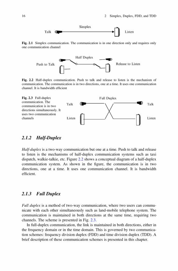
Simplex is a one-way communication such as broadcasting. Figure 2.1 shows asimplified diagram of a simplex communication system. The communication is inone direction only and requires only one communication channel.
© The Author(s), under exclusive license to Springer Nature Switzerland AG. 2019S. Faruque, Radio Frequency Multiple Access Techniques Made Easy,SpringerBriefs in Electrical and Computer Engineering,https://doi.org/10.1007/978-3-319-91651-4_2
15
2.1.2 Half-Duplex
Half-duplex is a two-way communication but one at a time. Push to talk and releaseto listen is the mechanisms of half-duplex communication systems such as taxidispatch, walkie-talkie, etc. Figure 2.2 shows a conceptual diagram of a half-duplexcommunication system. As shown in the figure, the communication is in twodirections, one at a time. It uses one communication channel. It is bandwidthefficient.
2.1.3 Full Duplex
Full duplex is a method of two-way communication, where two users can commu-nicate with each other simultaneously such as land-mobile telephone system. Thecommunication is maintained in both directions at the same time, requiring twochannels. The scheme is presented in Fig. 2.3.
In full-duplex communication, the link is maintained in both directions, either inthe frequency domain or in the time domain. This is governed by two communica-tion schemes: frequency division duplex (FDD) and time division duplex (TDD). Abrief description of these communication schemes is presented in this chapter.
Fig. 2.1 Simplex communication. The communication is in one direction only and requires onlyone communication channel
Fig. 2.2 Half-duplex communication. Push to talk and release to listen is the mechanism ofcommunication. The communication is in two directions, one at a time. It uses one communicationchannel. It is bandwidth efficient
Fig. 2.3 Full-duplexcommunication. Thecommunication is in twodirections simultaneously. Ituses two communicationchannels
16 2 Simplex, Duplex, FDD, and TDD

2.2 FDD and TDD Schemes
2.2.1 Background
Cellular communication is a full-duplex, multiple access communication system (seeFig. 2.4). According to the communication protocol, the cellular base station assignsa carrier frequency to the cell phone. Once the carrier frequency is assigned, the cellphone modulates the carrier frequency by means of voice, data, or video. It thenamplifies the modulated carrier frequency and sends it to the antenna fortransmission.
Upon receiving, the cellular radio at the base station responds to the cell phone bymeans of a similar communication protocol. The link is maintained in both direc-tions, either in the frequency domain or in the time domain. This is governed by:
• Frequency division duplex (FDD)• Time division duplex (TDD)
The two schemes are both widely used. Some cellular systems use TDD, whileothers use FDD. Some standards also allow for the use of either as both FDD andTDD have their own advantages and disadvantages. A brief description of thesecommunication modes are presented below:
2.2.2 Frequency Division Duplex (FDD)
In FDD, all the available channels are divided into two bands (lower band and upperband) and grouped as pairs (L1U1, L2U2. . . LnUn), as depicted in Fig. 1.3 [3, 4]. Ascan be seen, FDD uses two different frequencies, one for the upload and the other forthe download, separated by a guard band. As a result, both transmissions can takeplace at the same time without interference. This scheme is known as FDMA-FDDtechnique (Fig. 2.5). A brief description of FDD communication is presented below:
Fig. 2.4 Illustration of full-duplex cellularcommunication
2.2 FDD and TDD Schemes 17
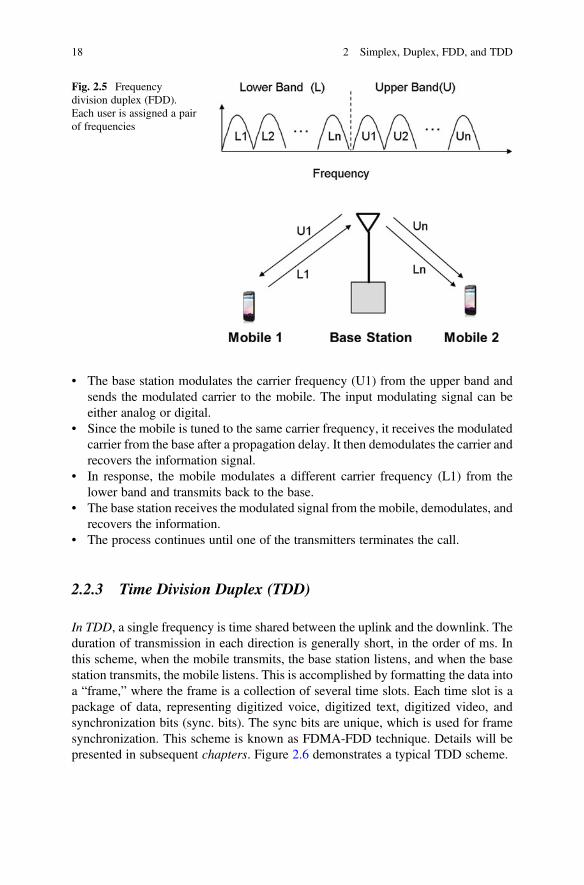
• The base station modulates the carrier frequency (U1) from the upper band andsends the modulated carrier to the mobile. The input modulating signal can beeither analog or digital.
• Since the mobile is tuned to the same carrier frequency, it receives the modulatedcarrier from the base after a propagation delay. It then demodulates the carrier andrecovers the information signal.
• In response, the mobile modulates a different carrier frequency (L1) from thelower band and transmits back to the base.
• The base station receives the modulated signal from the mobile, demodulates, andrecovers the information.
• The process continues until one of the transmitters terminates the call.
2.2.3 Time Division Duplex (TDD)
In TDD, a single frequency is time shared between the uplink and the downlink. Theduration of transmission in each direction is generally short, in the order of ms. Inthis scheme, when the mobile transmits, the base station listens, and when the basestation transmits, the mobile listens. This is accomplished by formatting the data intoa “frame,” where the frame is a collection of several time slots. Each time slot is apackage of data, representing digitized voice, digitized text, digitized video, andsynchronization bits (sync. bits). The sync bits are unique, which is used for framesynchronization. This scheme is known as FDMA-FDD technique. Details will bepresented in subsequent chapters. Figure 2.6 demonstrates a typical TDD scheme.
Fig. 2.5 Frequencydivision duplex (FDD).Each user is assigned a pairof frequencies
18 2 Simplex, Duplex, FDD, and TDD
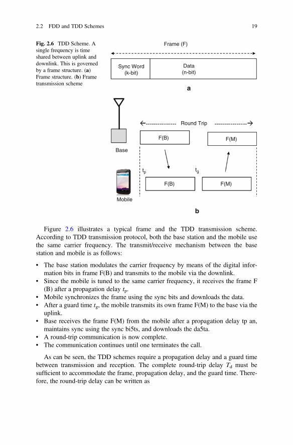
Figure 2.6 illustrates a typical frame and the TDD transmission scheme.According to TDD transmission protocol, both the base station and the mobile usethe same carrier frequency. The transmit/receive mechanism between the basestation and mobile is as follows:
• The base station modulates the carrier frequency by means of the digital infor-mation bits in frame F(B) and transmits to the mobile via the downlink.
• Since the mobile is tuned to the same carrier frequency, it receives the frame F(B) after a propagation delay tp.
• Mobile synchronizes the frame using the sync bits and downloads the data.• After a guard time tg, the mobile transmits its own frame F(M) to the base via the
uplink.• Base receives the frame F(M) from the mobile after a propagation delay tp an,
maintains sync using the sync bi5ts, and downloads the da5ta.• A round-trip communication is now complete.• The communication continues until one terminates the call.
As can be seen, the TDD schemes require a propagation delay and a guard timebetween transmission and reception. The complete round-trip delay Td must besufficient to accommodate the frame, propagation delay, and the guard time. There-fore, the round-trip delay can be written as
Frame (F)
Data(n-bit)
Round Trip
Base
Mobile
F(B)
F(B)
F(M)
F(M)
tgtp
a
b
Sync Word(k-bit)
Fig. 2.6 TDD Scheme. Asingle frequency is timeshared between uplink anddownlink. This is governedby a frame structure. (a)Frame structure. (b) Frametransmission scheme
2.2 FDD and TDD Schemes 19

Td ¼ 2 F þ tp þ tg� � ð2:1Þ
where:F ¼ frame lengthtp ¼ propagation delaytg ¼ guard timeIn cellular communications, such as OFDMA and LTE (4G), the traffic in both
directions is not balanced [5, 6]. There is scheduling protocol, which can bedynamically controlled to offer high-speed data over the downlink and low-speeddata over the uplink. In TDD, this is accomplished by transmitting more time slotsover the downlink, thereby supporting more capacity. For these reasons, TDD isused in 4G cellular system as WiMAX and LTE standards. Details will be presentedin later chapters.
2.3 Conclusions
A brief description of communication modes such as simplex, half-duplex, and fullduplex are presented in this chapter. Simplex is a one-way communication such asbroadcasting. Half-duplex is a two-way communication but one at a time such as taxidispatch system. Full duplex is referred to as a two-way communication, where twousers can communicate with each other simultaneously. The link is maintained inboth directions, either in the frequency domain or in the time domain. This isgoverned by two communication schemes: frequency division duplex (FDD) andtime-division duplex (TDD). These communication schemes as applied in the 4Gcellular system are also described in this chapter.
References
1. Milnor, J. W., & Randall, G. A. (2000). Simplex. In The IEEE authoritative dictionary ofstandard terms (7th ed., p. 1053). US: Institute of Electrical and Electronic Engineers.
2. Milnor, J. W., & Randall, G. A. (1931, May). The Newfoundland-Azores high-speed duplexcable. Canada: A.I.E.E. Electrical Engineering.
3. IS-54. (1989, December). Dual-mode mobile station-base station compatibility standard(EIA/TIA project number 2215).
4. IS-95. (1993, March 15).Mobile station - base station compatibility standard for dual mode wideband spread spectrum cellular systems (TR 45, PN-3115).
5. ITU-R. Requirements related to technical performance for IMT-Advanced radio interface(s)(Report M.2134), Approved in November 2008.
6. Parkvall, S., & Astely, D. (2009, April). The evolution of LTE toward LTE advanced. Journal ofCommunications, 4(3), 146–154. https://doi.org/10.4304/jcm.4.3.146-154.
20 2 Simplex, Duplex, FDD, and TDD

Chapter 3Frequency Division Multiple Access(FDMA)
Abstract FDMA (frequency division multiple access) is the oldest communicationtechnique used in broadcasting, land-mobile two-way radio, etc. It begins with aband of frequencies, which is allocated by the FCC (Federal CommunicationsCommission). This band of frequency is further divided into several narrow bandsof frequencies, where each frequency, also known as channel, is used for full-duplexcommunication. The communication link is maintained in both directions, either inthe frequency domain or in the time domain. This is governed by two basic modes ofoperations known as the Frequency Division Duplex (FDD) and Time DivisionDuplex (TDD). These topics, along with FDMA spectrum management and itsattributes, are presented in this chapter.
3.1 Introduction to FDMA
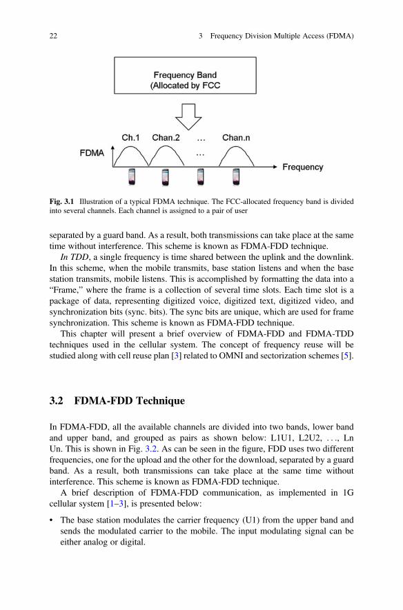
FDMA (frequency division multiple access) is the oldest communication techniqueused in broadcasting, land-mobile two-way radio, etc. [1–5, 8, 9]. It begins with aband of frequencies, which is allocated by the FCC (Federal CommunicationsCommission). FCC provides licenses to operate wireless communication systemsover the given bands of frequencies. These bands of frequencies are further dividedinto several channels and assigned to users for full-duplex communication.Figure 3.1 illustrates the basic principle of a typical FDMA technique.
As shown in the figure, the FCC-allocated frequency band is divided into severalfrequencies, also known as channels. Each channel is assigned to a single user. Inthis scheme, the channel is occupied for the entire duration of the call. The commu-nication link is maintained in both directions, either in the frequency domain or in thetime domain. This is governed by two basic mode of operations listed below:
• Frequency Division Duplex (FDD)• Time Division Duplex (TDD)
In FDD, all the available channels are divided into two bands, lower band andupper band, and grouped as pairs, one for the upload and the other for the download,
© The Author(s), under exclusive license to Springer Nature Switzerland AG. 2019S. Faruque, Radio Frequency Multiple Access Techniques Made Easy,SpringerBriefs in Electrical and Computer Engineering,https://doi.org/10.1007/978-3-319-91651-4_3
21
separated by a guard band. As a result, both transmissions can take place at the sametime without interference. This scheme is known as FDMA-FDD technique.
In TDD, a single frequency is time shared between the uplink and the downlink.In this scheme, when the mobile transmits, base station listens and when the basestation transmits, mobile listens. This is accomplished by formatting the data into a“Frame,” where the frame is a collection of several time slots. Each time slot is apackage of data, representing digitized voice, digitized text, digitized video, andsynchronization bits (sync. bits). The sync bits are unique, which are used for framesynchronization. This scheme is known as FDMA-FDD technique.
This chapter will present a brief overview of FDMA-FDD and FDMA-TDDtechniques used in the cellular system. The concept of frequency reuse will bestudied along with cell reuse plan [3] related to OMNI and sectorization schemes [5].
3.2 FDMA-FDD Technique
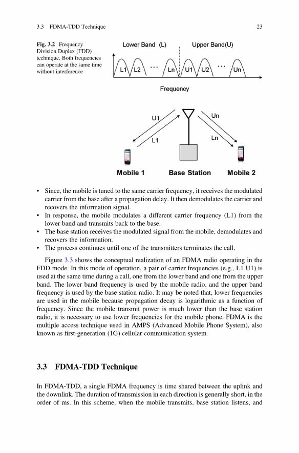
In FDMA-FDD, all the available channels are divided into two bands, lower bandand upper band, and grouped as pairs as shown below: L1U1, L2U2, . . ., LnUn. This is shown in Fig. 3.2. As can be seen in the figure, FDD uses two differentfrequencies, one for the upload and the other for the download, separated by a guardband. As a result, both transmissions can take place at the same time withoutinterference. This scheme is known as FDMA-FDD technique.
A brief description of FDMA-FDD communication, as implemented in 1Gcellular system [1–3], is presented below:
• The base station modulates the carrier frequency (U1) from the upper band andsends the modulated carrier to the mobile. The input modulating signal can beeither analog or digital.
Fig. 3.1 Illustration of a typical FDMA technique. The FCC-allocated frequency band is dividedinto several channels. Each channel is assigned to a pair of user
22 3 Frequency Division Multiple Access (FDMA)
• Since, the mobile is tuned to the same carrier frequency, it receives the modulatedcarrier from the base after a propagation delay. It then demodulates the carrier andrecovers the information signal.
• In response, the mobile modulates a different carrier frequency (L1) from thelower band and transmits back to the base.
• The base station receives the modulated signal from the mobile, demodulates andrecovers the information.
• The process continues until one of the transmitters terminates the call.
Figure 3.3 shows the conceptual realization of an FDMA radio operating in theFDD mode. In this mode of operation, a pair of carrier frequencies (e.g., L1 U1) isused at the same time during a call, one from the lower band and one from the upperband. The lower band frequency is used by the mobile radio, and the upper bandfrequency is used by the base station radio. It may be noted that, lower frequenciesare used in the mobile because propagation decay is logarithmic as a function offrequency. Since the mobile transmit power is much lower than the base stationradio, it is necessary to use lower frequencies for the mobile phone. FDMA is themultiple access technique used in AMPS (Advanced Mobile Phone System), alsoknown as first-generation (1G) cellular communication system.
3.3 FDMA-TDD Technique
In FDMA-TDD, a single FDMA frequency is time shared between the uplink andthe downlink. The duration of transmission in each direction is generally short, in theorder of ms. In this scheme, when the mobile transmits, base station listens, and
Fig. 3.2 FrequencyDivision Duplex (FDD)technique. Both frequenciescan operate at the same timewithout interference
3.3 FDMA-TDD Technique 23

when the base station transmits, mobile listens. This is accomplished by formattingthe data into a “Frame,” where the frame is a collection of several time slots. Eachtime slot is a package of data, representing digitized voice, digitized text, digitizedvideo, and synchronization bits (sync. bits). The sync bits are unique, which is usedfor frame synchronization. Figure 3.4 illustrates a typical frame and the TDDtransmission scheme.
According to TDD transmission, both the base station and the mobile use thesame carrier frequency. The transmit/receive mechanism between the base stationand mobile is as follows:
• The base station modulates the carrier frequency by means of the digital infor-mation bits in frame F(B) and transmits to the mobile.
• Since the mobile is tuned to the same carrier frequency, it receives the frame F(B) after a propagation delay tp.
• Mobile synchronizes the frame using the sync bits and downloads the data.• After a guard time tg, mobile transmits its own frame F(M) to the base using the
same carrier frequency.• Base receives the frame from the mobile after a propagation delay tp, maintains
sync using the sync bits, and downloads the data.• A round-trip communication is now complete.• The communication continues until one terminates the call.
As can be seen in the figure, the TDD schemes require a propagation delay and aguard time between transmission and reception. The complete round-trip delay Tdmust be sufficient to accommodate the frame, the propagation delay, and the guardtime. Therefore, the round-trip delay can be written as,
Fig. 3.3 FDMA-FDD radio. A pair of channels is used during a call: one from the lower band andone from the upper band
24 3 Frequency Division Multiple Access (FDMA)

Td ¼ 2 F þ tp þ tg� � ð3:1Þ
The round-trip delay Td depends on the frame length F, which is generally inmilliseconds (ms). The propagation delay tp depends on the propagation distance,and the guard time tg depends on the technology.
Figure 3.5 shows a conceptual realization of an FDMA radio operating in theTDD mode. In this technique, a single FDMA frequency is used in both directionsduring the entire duration of the call. This is accomplished by means of a specialframe structure as depicted in the figure. In this scheme, when the mobile transmits,base station listens, and when the base station transmits, mobile listens. This isbandwidth efficient, since a single-carrier frequency is used during the entire dura-tion of the call.
In cellular communications, such as OFDMA and LTE (4G), the traffic in bothdirections is not balanced. The volume of data transmission can be dynamicallyadjusted in each direction by means of FDD technique. There is schedulingprotocol, which can be dynamically controlled to offer high-speed data over thedownlink and low-speed data over the uplink. In TDD, this is accomplished bytransmitting more time slots over the downlink, thereby supporting more capacity.For these reasons, TDD is used in 4G cellular system as WiMAX and LTEstandards [6, 7].
Fig. 3.4 TDD framestructure. (a) Frame. (b)Frame transmission scheme
3.3 FDMA-TDD Technique 25
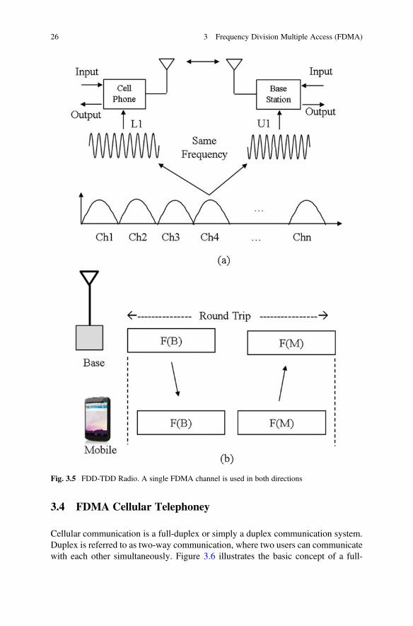
3.4 FDMA Cellular Telephoney
Cellular communication is a full-duplex or simply a duplex communication system.Duplex is referred to as two-way communication, where two users can communicatewith each other simultaneously. Figure 3.6 illustrates the basic concept of a full-
Fig. 3.5 FDD-TDD Radio. A single FDMA channel is used in both directions
26 3 Frequency Division Multiple Access (FDMA)
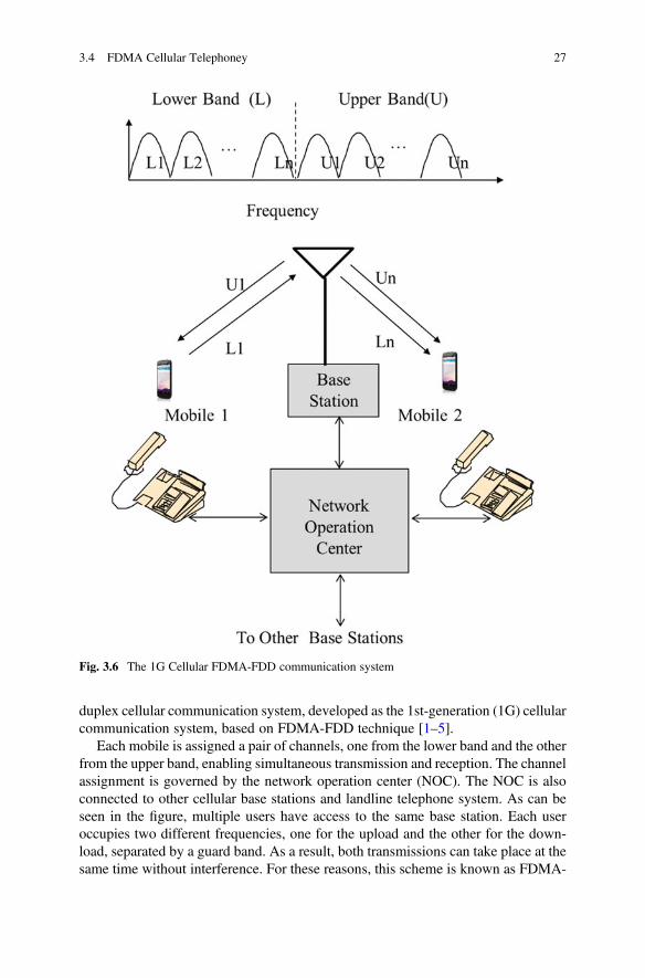
duplex cellular communication system, developed as the 1st-generation (1G) cellularcommunication system, based on FDMA-FDD technique [1–5].
Each mobile is assigned a pair of channels, one from the lower band and the otherfrom the upper band, enabling simultaneous transmission and reception. The channelassignment is governed by the network operation center (NOC). The NOC is alsoconnected to other cellular base stations and landline telephone system. As can beseen in the figure, multiple users have access to the same base station. Each useroccupies two different frequencies, one for the upload and the other for the down-load, separated by a guard band. As a result, both transmissions can take place at thesame time without interference. For these reasons, this scheme is known as FDMA-
Fig. 3.6 The 1G Cellular FDMA-FDD communication system
3.4 FDMA Cellular Telephoney 27

FDD technique. This forms the basis of 1G cellular communication system such asNorth American AMPS (Advanced Mobile Phone System) [1, 2] and EuropeanGSM (Group Special Mobile). This heralded a new era in cellular communication.Let’s take a closer look!
3.5 The Concept of Cell
A cell is a geographical area covered by radio-frequency (RF) signals. The RFsource is located at the center of the cell. Since RF propagation is fuzzy due toirregular terrain, vegetation, hills, buildings, etc., a practical cell will be highlyirregular. As a result, it will be difficult to analyze. For these reasons a hexagonalcellular geometry is used for planning and system dimensioning. This is depicted inFig. 3.7. The signal strength at the cell edge is the minimum signal strength that themobile can detect. This value is typically �100 dBm.
3.6 N ¼ 7 Cell Cluster
A hexagonal cell is surrounded by six hexagonal cells, forming a seven-cell cluster.This is also known as N ¼ 7 frequency reuse pattern. According to frequencyplanning, all the available frequencies are evenly distributed among seven cellsand then reused over and over to cover a given geographical area. This is depictedin Fig. 3.8.
Fig. 3.7 Illustration of ahexagonal cell, which isused for systemdimensioning
28 3 Frequency Division Multiple Access (FDMA)

3.7 N ¼ 3 Cell Cluster
Figure 3.9 shows a cluster of three cells. All the available channels are equallydistributed among three cells. This is known as N ¼ 3 frequency planning.According to frequency planning, all the available frequencies are evenly distributedamong three cells and then reused over and over to cover a given geographical area.Consequently, N ¼ 3 frequency planning offers more capacity.
3.8 Sectorization
The 120� sectorization is achieved by dividing a cell into three sectors, 120 degreeseach, as shown in Fig. 3.10a. Each sector is treated as a logical cell, where directionalantennas are used in each sector. Figure 3.10b shows an alternate representation,
Fig. 3.8 A 7 cell cluster.All the available frequenciesare evenly distributedamong seven cells
Fig. 3.9 A three-cellcluster. All the availablefrequencies are evenlydistributed among threecells
3.8 Sectorization 29

where each sector is represented by a hexagon. This configuration is known astri-cellular plan [5]. Both configurations are conceptually identical, while the latter isconvenient for channel assignment. Each sector uses a set of different channels.Adequate channel isolations are maintained within and between sectors in order tominimize interference. This is attributed to channel assignment techniques. Becausedirectional antennas are used in sectored cells, it allows antenna down tilt to improveC/I and channel capacity [5].
3.9 Spectrum Management
3.9.1 Background
The FCC (Federal Communications Commission) provides licenses to operatecellular communication systems over the given bands of frequencies. These bandsof frequencies are finite and have to be reused to provide services to other geographicareas. In frequency reuse plans, we dole out the channels to the cells, much like adealer in card game deals out cards from the deck until every player has a set. Severalfrequency reuse techniques, generally known as frequency planning or channelassignment techniques, are available. Some of the most widely used frequencyplanning techniques are given below [5, 10–15]:
• N ¼ 7 Frequency Reuse Plan• N ¼ 3 Frequency Reuse Plan
3.9.2 The N ¼ 7 Frequency Planning
Figure 3.11 shows a frequency plan in clusters of seven cells, known as N ¼ 7frequency plan. In this plan, all the available channels are evenly distributed amongseven cells. This is the first arrangement which works in most propagation environ-ments. There are also other frequency reuse plans, for example, N¼ 3, N¼ 4, N¼ 9,
Sector-1 Sector-2
Sector-3
a b
Sector-1 Sector-2
Sector-3
Fig. 3.10 Illustration of120� sectorization.Directional antennas areused in each sector. (a)Conventional representation(b) an alternaterepresentation, where eachsector is represented by ahexagon
30 3 Frequency Division Multiple Access (FDMA)
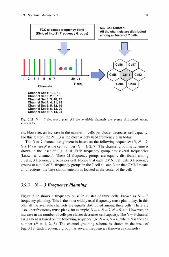
etc. However, an increase in the number of cells per cluster decreases cell capacity.For this reason, the N ¼ 3 is the most widely used frequency plan today.
The N ¼ 7 channel assignment is based on the following sequence: (N, N + 7,N + 14) where N is the cell number (N ¼ 1, 2, 7). The channel grouping scheme isshown in the inset of Fig. 3.10. Each frequency group has several frequencies(known as channels). These 21 frequency groups are equally distributed among7 cells, 3 frequency groups per cell. Notice that each OMNI cell gets 3 frequencygroups or a total of 21 frequency groups in the 7 cell cluster. Note that OMNI meansall directions; the base station antenna is located at the center of the cell.
3.9.3 N ¼ 3 Frequency Planning
Figure 3.12 shows a frequency reuse in cluster of three cells, known as N ¼ 3frequency planning. This is the most widely used frequency reuse plan today. In thisplan all the available channels are equally distributed among three cells. There arealso other frequency reuse plans, for example, N¼ 4, N¼ 7, N¼ 9, etc. However, anincrease in the number of cells per cluster decreases cell capacity. The N¼ 3 channelassignment is based on the following sequence: (N, N + 3, N + 6) where N is the cellnumber (N ¼ 1, 2, 3). The channel grouping scheme is shown in the inset ofFig. 3.12. Each frequency group has several frequencies (known as channels).
Channels
1 2 3 4 5 6 7 20 21
Cell6
FCC allocated frequency band(Divided into 21 Frequency Groups)
N=7 Cell Cluster:All the channels are distributedamong a cluster of 7 cells
Cell7
Cell1Cell5
Cell4 Cell3
Cell2
F req.
Channel Set 1: 1, 8, 15Channel Set 2: 2, 9, 16Channel Set 3: 3, 10, 17Channel Set 4: 4, 11, 18Channel Set 5: 5, 12, 19Channel Set 6: 6, 13, 20Channel Set 7: 7, 14, 21
Fig. 3.11 N ¼ 7 frequency plan. All the available channels are evenly distributed amongseven cells
3.9 Spectrum Management 31

3.10 Conclusions
FDMA (frequency division multiple access) is the oldest communication techniqueused in broadcasting, land-mobile two-way radio, etc. It begins with a band offrequencies, which is allocated by the FCC (Federal Communications Commission).This band of frequency is further divided into several narrow bands of frequencies,where each frequency, also known as channel, is used for full-duplex communica-tion. The communication link is maintained in both directions, either in the fre-quency domain or in the time domain. This is governed by two basic modes ofoperations known as Frequency Division Duplex (FDD) and Time Division Duplex(TDD).
This chapter presents a brief overview of FDMA along with FDD and TDD modeof operations. The FDMA cellular communications is described along with variousspectrum management techniques.
References
1. IS-54. (1989, December). Dual-mode mobile station-base station compatibility standard(EIA/TIA project number 2215).
2. IS-95. (1993, March 15). Mobile station - base station compatibility standard for dual modewide band spread spectrum cellular systems (TR 45, PN-3115).
3. Mac Donald, V. H. (1979, January). The cellular concept. The Bell System Technical Journal,58(1), IS–41.
4. Lee, W. C. Y. (1989). Mobile cellular telecommunications systems. New York: McGraw-Hill.
Channels
FCC allocated frequency band(Divided into 9 Frequency Groups)
N=3 Cell Cluster:All the channels are distributedamong a cluster of 3 cells
F req.84321 9
14
3 258
69
7
Channel Set 1: 1, 4, 7Channel Set 2: 2, 5, 8Channel Set 3: 3, 6, 9
Fig. 3.12 N ¼ 3 frequency plant. All the available channels are evenly distributed among threecells
32 3 Frequency Division Multiple Access (FDMA)

5. Faruque, S. (1996). Cellular mobile systems engineering. Norwood: Artech House, ISBN:0-89006-518-7.
6. ITU-R. Requirements related to technical performance for IMT-Advanced radio interface(s)(Report M.2134), Approved in November 2008.
7. Parkvall, S., & Astely, D. (April 2009). The evolution of LTE toward LTE advanced. Journal ofCommunications, 4(3), 146–154. https://doi.org/10.4304/jcm.4.3.146-154.
8. ITU, International Telecommunications Union, Paris, France.9. FCC, Federal Communication Commission, Washington, DC.
10. Faruque, S. Directional frequency allocation in an N¼6 cellular radio system (US Patent:5,802,474), Granted, 1 September 1998.
11. Faruque, S. Frequency assignment in a cellular radio system (US Patent: 5,734,983), Granted31 March 1998.
12. Faruque, S. Frequency plan for a cellular network (US Patent: 5,483,667), Granted, 9 January1996.
13. Faruque, S. High capacity cell planning based on fractional frequency reuse (US Patent:6,128,497), Granted, 3 October 2000.
14. Faruque, S. Frequency transition process for capacity enhancement in a cellular network(US Patent: 6,085,093), Granted, 4 July 2000.
15. Faruque, S. N¼4 directional frequency assignment in a cellular radio system (US Patent:5,970,411), Granted, 19 October 1999.
References 33

Chapter 4Time Division Multiple Access (TDMA)
Abstract Time division multiple access (TDMA) is a method of transmitting andreceiving multiple independent signals over a single transmission channel. TheTDMA at the transmit side, known as the multiplexer, assigns multiple channels inpreassigned time slots. The TDMA at the receive side, known as the de-multiplexer,separates the incoming composite signal into parallel streams. Both multiplexer andde-multiplexer are synchronized by a common clock to receive data in accordancewith the transmit sequence. This chapter presents the key concepts, underlyingprinciples and practical applications of TDMA used in land-mobile telecommunica-tion systems.
4.1 Introduction to TDMA
TDMA (time division multiple access) for wireless communication is an extensionof FDMA, where each FDMA channel is time shared by multiple users, one at atime. It begins with a band of frequencies, which is allocated by the FCC (FederalCommunications Commission). This band of frequency is further divided intoseveral narrow bands of frequencies, where each frequency, also known as channel,is used for full-duplex communication by multiple users one at a time as depicted inFig. 4.1.
Figure 4.2 illustrates the basic concept of a full-duplex cellular communicationsystem, developed as the 2nd-generation (2G) cellular communication system, basedon TDMA-FDD technique [1–6]. In this technique, a pair of FDMA channel is usedduring a call, one from the lower band and one from the upper band. The lower bandfrequency is time shared by several mobiles. The upper band frequency is also timeshared synchronously by the base station radio. Both channels are occupied duringthe entire duration of the call.
Synchronization is achieved by means of a special frame structure, where theframe is a collection of time slots. Each time slot is assigned to a mobile. This impliesthat, when one mobile has access to the channel, the other mobiles are idle.
© The Author(s), under exclusive license to Springer Nature Switzerland AG. 2019S. Faruque, Radio Frequency Multiple Access Techniques Made Easy,SpringerBriefs in Electrical and Computer Engineering,https://doi.org/10.1007/978-3-319-91651-4_4
35
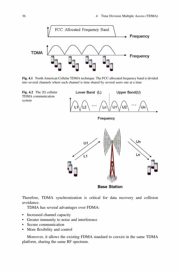
Therefore, TDMA synchronization is critical for data recovery and collisionavoidance.
TDMA has several advantages over FDMA:
• Increased channel capacity• Greater immunity to noise and interference• Secure communication• More flexibility and control
Moreover, it allows the existing FDMA standard to coexist in the same TDMAplatform, sharing the same RF spectrum.
Fig. 4.1 North American Cellular TDMA technique. The FCC-allocated frequency band is dividedinto several channels where each channel is time shared by several users one at a time
Fig. 4.2 The 2G cellularTDMA communicationsystem
36 4 Time Division Multiple Access (TDMA)

4.2 TDMA Frame Structure
The TDMA air link is based on a 40 ms frame structure, equally divided into six timeslots, 6.667 ms each. Each of the six time slots contains 324 gross bit intervals,corresponding to 162 symbols (1 symbol ¼ 2 bits of information). Figure 4.3 showsthe forward link (base to mobile) TDMA frame structure. In TDMA-3, the time slotsare paired as 1–4, 2–5, and 3–6 where each disjoints pair of time slots are assigned toa mobile. This arrangement enables three mobiles to access the same 30 kHz channelone at a time.
The TDMA-3 forward link uses a rate 1/2 convolutional encoding with interleav-ing. The encoded 48.6 kb/s data bit stream is modulated by means of a π/4 DQPSKmodulation and then transmitted from the base station to the mobile where eachmobile receives data at 16.2 kb/s. At the receive side the RF signal is demodulatedand decoded, and finally the original data is recovered. Since this is a radio channel,the recovered data is impaired by noise, interference, and fading. As a result, theinformation is subject to degradation. Although error control coding greatlyenhances the performance, the C/I (carrier-to-interference ratio) is still the limitingfactor. The TDMA-3 reverse link is exactly the reverse process.
Problem 4.1Given:• Frame length ¼ 40 ms (Figure below).• The frame contains six time slots and supports three users.• Each user originates 16.2 kbps data.
Fig. 4.3 TDMA forward link format
4.2 TDMA Frame Structure 37

Find:
(a) A suitable multiplexing structure(b) The composite data rate in the channel(c) Number of bits/Frame
Solution:
(a) We have three users and six time slots. Therefore we can assign two time slots/user:
• User-1: Time slot 1 and 4• User-2: Time slot 2 and 5• User-3: Time slot 3 and 6
38 4 Time Division Multiple Access (TDMA)
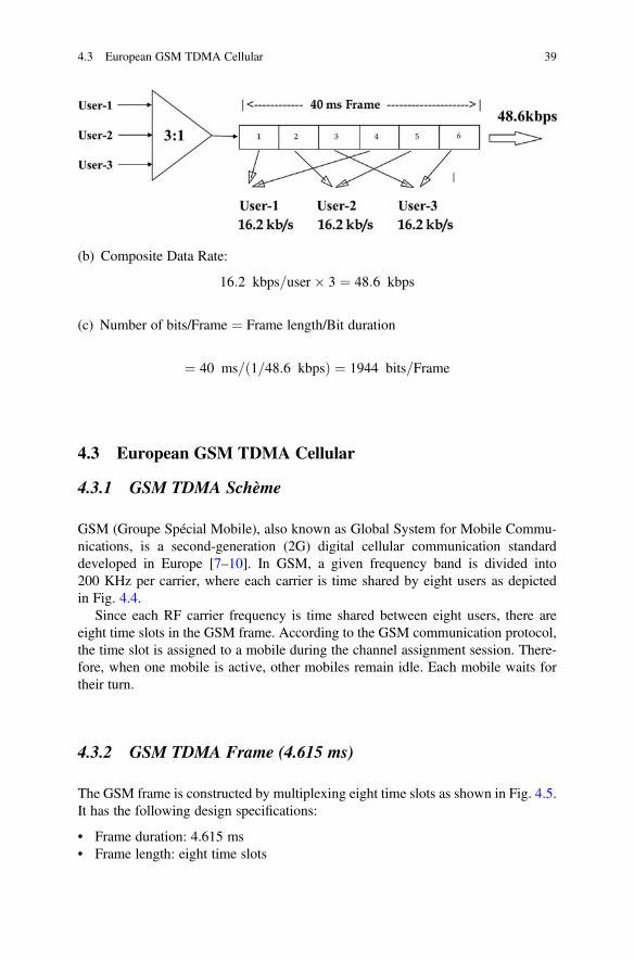
(b) Composite Data Rate:
16:2 kbps=user � 3 ¼ 48:6 kbps
(c) Number of bits/Frame ¼ Frame length/Bit duration
¼ 40 ms= 1=48:6 kbpsð Þ ¼ 1944 bits=Frame
4.3 European GSM TDMA Cellular
4.3.1 GSM TDMA Schème
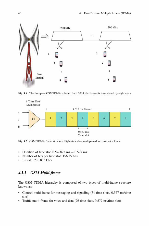
GSM (Groupe Spécial Mobile), also known as Global System for Mobile Commu-nications, is a second-generation (2G) digital cellular communication standarddeveloped in Europe [7–10]. In GSM, a given frequency band is divided into200 KHz per carrier, where each carrier is time shared by eight users as depictedin Fig. 4.4.
Since each RF carrier frequency is time shared between eight users, there areeight time slots in the GSM frame. According to the GSM communication protocol,the time slot is assigned to a mobile during the channel assignment session. There-fore, when one mobile is active, other mobiles remain idle. Each mobile waits fortheir turn.
4.3.2 GSM TDMA Frame (4.615 ms)
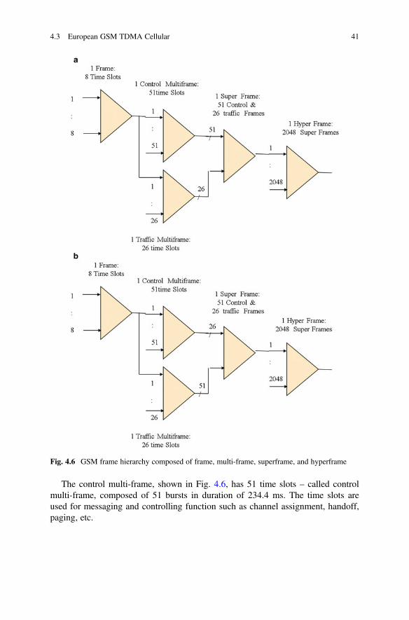
The GSM frame is constructed by multiplexing eight time slots as shown in Fig. 4.5.It has the following design specifications:
• Frame duration: 4.615 ms• Frame length: eight time slots
4.3 European GSM TDMA Cellular 39
• Duration of time slot: 0.576875 ms ¼ 0.577 ms• Number of bits per time slot: 156.25 bits• Bit rate: 270.833 kb/s
4.3.3 GSM Multi-frame
The GSM TDMA hierarchy is composed of two types of multi-frame structureknown as:
• Control multi-frame for messaging and signaling (51 time slots, 0.577 ms/timeslot)
• Traffic multi-frame for voice and data (26 time slots, 0.577 ms/time slot)
Fig. 4.4 The European GSMTDMA scheme. Each 200 kHz channel is time shared by eight users
Fig. 4.5 GSM TDMA frame structure. Eight time slots multiplexed to construct a frame
40 4 Time Division Multiple Access (TDMA)
The control multi-frame, shown in Fig. 4.6, has 51 time slots – called controlmulti-frame, composed of 51 bursts in duration of 234.4 ms. The time slots areused for messaging and controlling function such as channel assignment, handoff,paging, etc.
Fig. 4.6 GSM frame hierarchy composed of frame, multi-frame, superframe, and hyperframe
4.3 European GSM TDMA Cellular 41
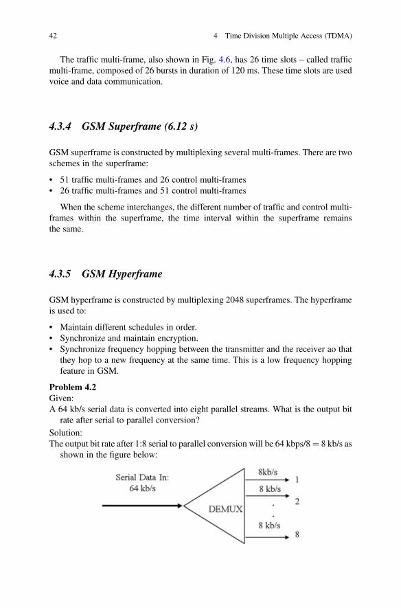
The traffic multi-frame, also shown in Fig. 4.6, has 26 time slots – called trafficmulti-frame, composed of 26 bursts in duration of 120 ms. These time slots are usedvoice and data communication.
4.3.4 GSM Superframe (6.12 s)
GSM superframe is constructed by multiplexing several multi-frames. There are twoschemes in the superframe:
• 51 traffic multi-frames and 26 control multi-frames• 26 traffic multi-frames and 51 control multi-frames
When the scheme interchanges, the different number of traffic and control multi-frames within the superframe, the time interval within the superframe remainsthe same.
4.3.5 GSM Hyperframe
GSM hyperframe is constructed by multiplexing 2048 superframes. The hyperframeis used to:
• Maintain different schedules in order.• Synchronize and maintain encryption.• Synchronize frequency hopping between the transmitter and the receiver ao that
they hop to a new frequency at the same time. This is a low frequency hoppingfeature in GSM.
Problem 4.2Given:A 64 kb/s serial data is converted into eight parallel streams. What is the output bit
rate after serial to parallel conversion?
Solution:The output bit rate after 1:8 serial to parallel conversion will be 64 kbps/8¼ 8 kb/s as
shown in the figure below:
42 4 Time Division Multiple Access (TDMA)

Problem 4.3Given:Eight parallel data streams, having 8 kb/s each, is parallel to serial converted to form
a composite bit stream. What is the output bit rate after 8:1 parallel to serialconversion?
Solution:The output bit rate after 8:1 parallel to serial conversion will be 8 kb/s� 8¼ 64 kb/s
as shown in the figure below:
4.4 Conclusions
• Defined TDMA• Described TDMA frame and frame hierarchy used in North American and
European Land Telephone System• Illustrated Frame Synchronization Process• Reviewed North American TDMA and European GSM TDMA System used in
Wireless Communications• Illustrated TDMA Frame and Frame Hierarchy
References
1. Smith, D. R. (1984). Digital transmission systems. New York: Van Nostrand Reinhold Com-pany, ISBN: 0442009178.
2. Couch, L. W., II. (2001). Digital and analog communication systems (7th ed.). EnglewoodCliffs, NJ: Prentice-Hall, ISBN: 0-13-142492-0.
3. Faruque, S., & Baxter, S. (1989). Nortel internal training course, 1995 and IS-54 (EIA ProjectNumber 2215), pp. 3/18–3/47.
4. Mac Donald, V. H. (1979, January) Advanced mobile phone services. Special Issue, Bell SystemTechnical Journal, 58, 12–41.
5. Lee, W. C. Y. (1989). Mobile cellular telecommunications systems. New York: McGraw-Hill.6. Faruque, S. (1996). Cellular Mobile Systems Engineering. Boston: Artech House, ISBN:
0-89006-518-7.7. Proakis, J. G., & Salehi, M. (2014). Fundamenttals of Communication System (2nd ed.).
Boston: Pearson, ISBN-13: 978-0-13-335485-0.8. European Telecommunications Standards Institute. (2011). GSM. etsi.org.9. GSM Association. (2001). History. gsmworld.com.
10. European Telecommunications Standards Institute. (2011). Cellular history. etsi.org. Archivedfrom the original on 5 May 2011.
References 43

Chapter 5Code Division Multiple Access (CDMA)
Abstract This chapter presents a brief overview of spread spectrum technique andshows how it relates to CDMA technology. Orthogonal codes and their propertiesare presented and show how orthogonal codes are generated and used to designCDMA radio. It is shown that CDMA capacity directly relates to code length.
Objectives
• Review spread spectrum and show how it relates to process gain and CDMAcapacity.
• Understand orthogonal codes and show how orthogonal codes are used to designCDMA Radio.
• Estimate CDMA capacity and show how it relates to code length.• Recognize the need for power control and show how it relates to CDMA
operation.
5.1 Introduction to CDMA
CDMA (code division multiple access) is a spread spectrum (SS) communicationsystem where multiple users have access to the same career frequency at the sametime [1–5]. It begins with a frequency band, allocated by the Federal CommunicationCommission (FCC) as shown in Fig. 5.1. FCC provides licenses to operate wirelesscommunication systems over given bands of frequencies. These frequency bands arefinite and have to be reused to support a large number of users in a given geograph-ical area.
Figure 5.2 shows the construction of a simple CDMA radio. At the transmit side,the input encoded low-speed NRZ data (D) is multiplied by a high-speed orthogonalcode (C) for spectrum spreading. Multiplication in this process is referred to asexclusive OR (EXOR) operation. The output of the exclusive OR gate Y is thenmodulated and transmitted through the radio-frequency (RF) channel.
© The Author(s), under exclusive license to Springer Nature Switzerland AG. 2019S. Faruque, Radio Frequency Multiple Access Techniques Made Easy,SpringerBriefs in Electrical and Computer Engineering,https://doi.org/10.1007/978-3-319-91651-4_5
45

At the receive side, the incoming RF signal is demodulated to recover thecomposite digital signal Y that contains both D and C. The receiver then multipliesY by using the same orthogonal code C to recover the original data D. The operationis governed by the following Boolean expressions:
• Y ¼ D EXOR C• D ¼ Y EXOR C
¼ D EXOR C EXOR C¼ D
where
• D ¼ Input NRZ Data• C ¼ n-bit Orthogonal Code• EXOR C EXOR C ¼ 0
The objective of this chapter is to review spectrum, spectrum spreading, anddispreading techniques and shows how it relates to spread spectrum CDMA radio.Orthogonal codes and their properties are presented and show how orthogonal codesare used in CDMA radio and to estimate channel capacity. CDMA is a noise-limitedsystem. Therefore, the need for power control is also described for reliable operation.
Fig. 5.1 FCC-allocated frequency band and its use in CDMA as spread spectrum. Multiple usershave access to the same frequency at the same time
Fig. 5.2 The basic CDMA radio. (a) Transmitter. (b) Receiver
46 5 Code Division Multiple Access (CDMA)

5.2 Spectrum of NRZ Data
Let’s consider the discrete time signal as shown in Fig. 5.3, having the followingboundary conditions [5]:
V tð Þ ¼ V¼ 0
< 0 < t < Telsewhere
ð5:1Þ
This signal is also known as NRZ (non-return-to-zero) data, generally used indigital radio. Now, our goal is to determine the frequency content of this signal andthen to evaluate the power spectrum associated with this signal. According to Fouriertransform, the time domain signal is given by,
V ωð Þ ¼ZT
0
V :e�jω tdt
¼ 2V
ω
� �sin ωT=2ð Þ
¼ VTsin ωT=2ð ÞωT=2
� �ð5:2Þ
The corresponding power spectral density is given by,
P ωð Þ ¼ 1T
� �V ωð Þj j2
¼ V2Tsin ωT=2ð ÞωT=2
� �2 ð5:3Þ
Figure 5.4 is the familiar power spectrum, showing the main lobe correspondingto the fundamental component of the frequency and infinite number of side lobescorresponding to the harmonic components. We also note that most of the power is
Fig. 5.3 A non-return-to-zero (NRZ) data
5.2 Spectrum of NRZ Data 47

retained by the main lobe whose bandwidth is given by, BW¼ 2f, where f¼ bit rate.It may be noted that the two-sided power spectrum will be shifted and centered onthe carrier frequency after modulation.
5.3 Spectrum Spreading
5.3.1 Basic Concept
Spectrum spreading can be achieved by simply increasing the frequency of thediscrete time signal. Thus we consider a waveform with an amplitude V andfrequency f (f ¼ 1/T) and then increase the frequency of the same waveform by afactor of n, i.e., T is now reduced by n. Pair of boundary conditions describing thesesignals are as follows:
V tð Þ ¼ V < 0 < t < T¼ 0 elsewhere
V tð Þ ¼ V < 0 < t < T=n¼ 0 elsewhere
ð5:4Þ
Applying the Fourier transform in the above equations, we obtain thecorresponding frequency domain signals as follows:
For 0 � t � T:
V ωð Þ ¼ZT
0
V :e�jωtdt ¼ VTsin ωT=2ð ÞωT=2
� �ð5:5Þ
Time
V
TP(ω)
P(ω)
FrequencyFrequency
f 2f −2f−f f 2f03f
a b c
Fig. 5.4 Power spectrum of NRZ data. (a) NRZ data. (b) One-sided power spectrum.(c) Two-sided power spectrum. The two-sided power spectrum will be shifted and centered onthe carrier frequency after modulation
48 5 Code Division Multiple Access (CDMA)

P ωð Þ ¼ 1T
� �S ωð Þj j2 ¼ V2T
sin ωT=2ð ÞωT=2
� �2ð5:6Þ
For 0 � t � T/n:
V ωð Þ ¼ZT
0
V :e�jωtdt ¼ VTsin ωT=2nð ÞωT=2n
� �
P ωð Þ ¼ 1T
� �S ωð Þj j2 ¼ V2T
sin ωT=2nð ÞωT=2n
� �2ð5:7Þ
Figure 5.5 shows the power spectrum for n¼ 1 and n¼ 2, where n1 relates to thelow frequency signal and n2 relates to the high frequency signal. In this particularexample, the latter is twice the frequency of the former.
5.3.2 Energy Delivered
The energy delivered into a load between time t ¼ 0 and t ¼ T is given by the totalarea under the curve.
E tð Þ ¼ZT
0
P ωð Þdt ¼ 1T
� �ZT
0
S ωð Þj j2dt ¼ constant ð5:8Þ
This means that the total energy under the power spectrum curve remains thesame after spreading. It follows that if we increase the bandwidth by a certain factor,the amplitude will be reduced by the same factor. This is because of conservation ofenergy.
Fig. 5.5 Illustration ofspectrum of two signalshaving different frequencies
5.3 Spectrum Spreading 49
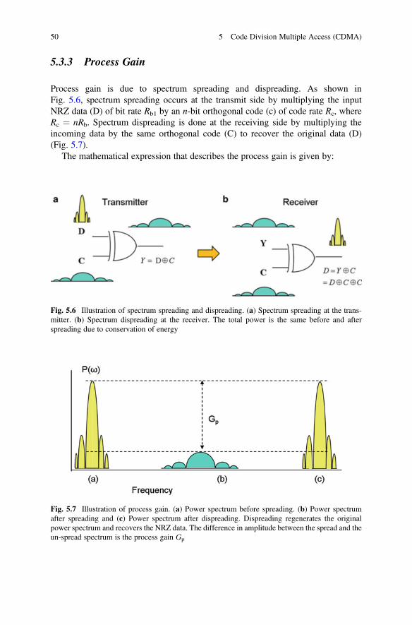
5.3.3 Process Gain
Process gain is due to spectrum spreading and dispreading. As shown inFig. 5.6, spectrum spreading occurs at the transmit side by multiplying the inputNRZ data (D) of bit rate Rb1 by an n-bit orthogonal code (c) of code rate Rc, whereRc ¼ nRb. Spectrum dispreading is done at the receiving side by multiplying theincoming data by the same orthogonal code (C) to recover the original data (D)(Fig. 5.7).
The mathematical expression that describes the process gain is given by:
Fig. 5.6 Illustration of spectrum spreading and dispreading. (a) Spectrum spreading at the trans-mitter. (b) Spectrum dispreading at the receiver. The total power is the same before and afterspreading due to conservation of energy
Fig. 5.7 Illustration of process gain. (a) Power spectrum before spreading. (b) Power spectrumafter spreading and (c) Power spectrum after dispreading. Dispreading regenerates the originalpower spectrum and recovers the NRZ data. The difference in amplitude between the spread and theun-spread spectrum is the process gain Gp
50 5 Code Division Multiple Access (CDMA)

Gp dBð Þ ¼ 10logRc
Rb
� �
¼ 10log nð Þð5:9Þ
where
• Gp ¼ Process gain• Rc ¼ Code rate• Rb ¼ Bit rate• n ¼ Code length
For example, if the orthogonal code length is 2 (n¼ 2), the corresponding processgain will be Gp(dB) ¼ 10log(2) ¼ 3 dB. This is an additional dB margin, whichimproves the signal to noise ratio (S/N) by 3 dB. Similarly, if the orthogonal codelength is 64 (n ¼ 64), the corresponding process gain will be Gp(dB) ¼ 10log(64) ¼ 18 dB, and the additional margin in S/N is 18 dB. Table 5.1 shows the dBmargins associated with a few orthogonal codes.
It appears that, in CDMA, process gain improves S/N, which leads to CDMAcapacity.
5.4 A Tour of Orthogonal Codes
Orthogonal codes, also known as Walsh codes, were originally developed by J. L.Walsh in 1923. Walsh codes are well known for their orthogonal properties. Theyhave been successfully implemented in CDMA for spreading and user ID. The use oforthogonal codes for Forward Error Control Coding (FECC) has also been investi-gated by a limited number of authors. In this chapter, our goal is to show howorthogonal codes are generated and used in CDMA to support multiple users at thesame time in a given channel.
Table 5.1 dB margins due tospectrum spreading
Code length (n) Process gain (dB)
2 3.0103
4 6.0206
8 9.0309
16 12.0412
32 15.0515
64 18.0618
5.4 A Tour of Orthogonal Codes 51
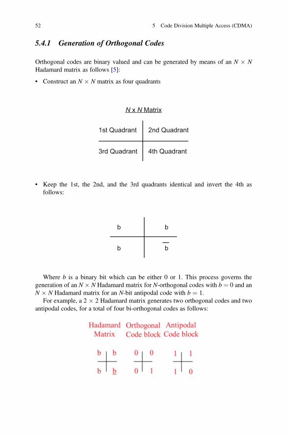
5.4.1 Generation of Orthogonal Codes
Orthogonal codes are binary valued and can be generated by means of an N � NHadamard matrix as follows [5]:
• Construct an N � N matrix as four quadrants
1st Quadrant 2nd Quadrant
3rd Quadrant 4th Quadrant
N x N Matrix
• Keep the 1st, the 2nd, and the 3rd quadrants identical and invert the 4th asfollows:
b b
b b
Where b is a binary bit which can be either 0 or 1. This process governs thegeneration of an N � N Hadamard matrix for N-orthogonal codes with b ¼ 0 and anN � N Hadamard matrix for an N-bit antipodal code with b ¼ 1.
For example, a 2 � 2 Hadamard matrix generates two orthogonal codes and twoantipodal codes, for a total of four bi-orthogonal codes as follows:
52 5 Code Division Multiple Access (CDMA)
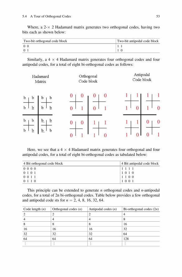
Where, a 2-� 2 Hadamard matrix generates two orthogonal codes, having twobits each as shown below:
Two-bit orthogonal code block Two-bit antipodal code block
0 00 1
1 11 0
Similarly, a 4 � 4 Hadamard matrix generates four orthogonal codes and fourantipodal codes, for a total of eight bi-orthogonal codes as follows:
Here, we see that a 4 � 4 Hadamard matrix generates four orthogonal and fourantipodal codes, for a total of eight bi-orthogonal codes as tabulated below:
4 Bit orthogonal code block 4 Bit antipodal code block
0 0 0 00 1 0 10 0 1 10 1 1 0
1 1 1 11 0 1 01 1 0 01 0 0 1
This principle can be extended to generate n orthogonal codes and n-antipodalcodes, for a total of 2n bi-orthogonal codes. Table below provides a few orthogonaland antipodal code sts for n ¼ 2, 4, 8, 16, 32, 64.
Code length (n) Orthogonal codes (n) Antipodal codes (n) Bi-orthogonal codes (2n)
2 2 2 4
4 4 4 8
8 8 8 16
16 16 16 32
32 32 32 64
64 64 64 128
⋮ ⋮ ⋮ ⋮
5.4 A Tour of Orthogonal Codes 53

5.4.2 Bi-orthogonal Codes
In the above, we have established that orthogonal codes are binary valued and haveequal numbers of 1’s and 0’s. Antipodal codes, on the other hand, are just the inverseof orthogonal codes. Antipodal codes are also orthogonal among themselves. There-fore, an n-bit orthogonal code has n-orthogonal codes and n-antipodal codes, for atotal of 2n bi-orthogonal codes. For example, an eight-bit orthogonal code has eightorthogonal codes and eight antipodal codes, for a total of 16 bi-orthogonal codes asshown in Fig. 5.8.
Similarly, a 16-bit orthogonal code has 16 orthogonal code and 16-antipodal codefor a total of 32 bi-orthogonal codes, as shown in Fig. 5.9. We will take thisbi-orthogonal codes block as an example and examine the error control properties.
Orthogonal Code
0 0 0 0 0 0 0 0 1 1 1 1 1 1 1 11 0 1 0 1 0 1 00 1 0 1 0 1 0 1
0 0 1 1 0 0 1 10 1 1 0 0 1 1 00 0 0 0 1 1 1 10 1 0 1 1 0 1 00 0 1 1 1 1 0 00 1 1 0 1 0 0 1
1 1 0 0 1 1 0 01 0 0 1 1 0 0 1
1 1 1 1 0 0 0 01 0 1 0 0 1 0 11 1 0 0 0 0 1 11 0 0 1 0 1 1 0
Antipodal CodeFig. 5.8 Bi-orthogonalcode set for n ¼ 8. An 8-bitorthogonal code has eightorthogonal code and eightantipodal code for a total of16 bi-orthogonal codes
16 Bit Orthogonal Code
0 0 0 0 0 0 0 0 0 0 0 0 0 0 0 0 1 1 1 1 1 1 1 1 1 1 1 1 1 1 1 11 0 1 0 1 0 1 0 1 0 1 0 1 0 1 0
1 1 0 0 1 1 0 0 1 1 0 0 1 1 0 01 0 0 1 1 0 0 1 1 0 0 1 1 0 0 1
0 0 0 00 0 0 01 1 1 1 1 1 1 1
1 0 1 0 1 0 1 00 1 0 1 0 1 0 1
1 1 0 0 1 1 0 00 0
0 0 0 0 0 0 0 0
1 1 0 0 1 1
1 0 0 1
1 0 0 1 1 0 0 1 0 1 1 0 0 1 1 0
1 1 1 1
1 0 1 0 1 0 1 00 1 0 10 1 0 11 1 0 0 1 1 0 00 0 1 10 0 1 11 0 0 1 1 0 0 10 1 1 00 1 1 0
1 1 1 1
1 0 0 10 1 1 0 0 1 1 01 1 1 1 1 1 1 1 0 0 0 0 0 0 0 0
1 0 1 0 1 0 1 0 0 1 0 1 0 1 0 1
1 1 0 0 1 1 0 0 0 0 1 1 0 0 1 1
0 1 0 1
0 1 0 1
0 1 0 1
0 1 0 10 1 0 1
0 1 0 1
0 1 0 11 0 1 0
1 0 1 0
1 0 1 0 1 0 1 0
1 0 1 0
1 0 1 0
0 0 1 1
0 0 1 1
0 0 1 1
0 0 1 1 0 0 1 1
0 0 1 1
0 1 1 0
0 1 1 0
0 1 1 0 0 1 1 0
0 1 1 0
0 1 1 00 0 1 11 1 0 0
1 1 0 0 1 1 0 0
1 1 0 0
0 1 1 0 0 1 1 0 0 1 1 0 0 1 1 00 0 0 0
0 0 0 0
0 0 0 0
1 0 0 1 1 0 0 1
0 0 0 0
0 0 0 0
0 0 0 01 1 1 1
1 1 0 0 1 1 0 0
1 1 1 1
1 1 1 1 1 1 1 1
1 1 1 1
1 0 0 1
1 0 0 1 1 0 0 1
1 0 0 1
1 1 1 1
0 0 1 1 0 0 1 1 0 0 1 1
0 1 0 1 0 1 0 1 0 1 0 1
16 Bit Antipodal Code
Fig. 5.9 Bi-orthogonal code set for n ¼ 16. A 16-bit orthogonal code has 16 orthogonal code and16-antipodal code for a total of 32 bi-orthogonal codes
54 5 Code Division Multiple Access (CDMA)

Thus we conclude that an orthogonal code has the following properties:Binary valued
• Has equal number of 1’s and 0’s• Zero cross-correlation property
5.5 Orthogonal Codes for Data Spreading and De-spreading
In CDMA, each user is assigned a unique n-bit orthogonal code as a user ID,spectrum spreading at the transmit side, and dispreading at the receive side. Spec-trum spreading is accomplished by multiplying each NRZ data bit by means of an n-bit orthogonal code. Multiplication in this process is referred to as exclusive OR(EXOR) operation. The output of the EXOR (Exclusive OR gate) is now a high-speed orthogonal or antipodal code. De-spreading is a similar process, where thereceiver multiplies the incoming data by means of the same orthogonal code andrecovers the data. Let’s examine these operations using a 4-bit orthogonal code,where the code sequence is given by 0011 and the input NRZ data is 0 and 1.
5.5.1 Spreading Bit 0 and De-spreading to Recover Bit 0
This is shown in Fig. 5.10. When the binary bit 0 is multiplied by a 4-bit orthogonalcode 0011, we write,
0 EXOR 0011ð Þ ¼ 0011 ð5:10Þ
This is the orthogonal code, reproduced due to exclusive OR operation. More-over, the bit rate is also multiplied by a factor of four, thereby spreading the spectrumby a factor of four as well. This is the wide-band data which is transmitted to thereceiver. Upon receiving 0011, the receiver performs the de-spreading function
D = 0
D=0
C=0011C=0011
Y=0011
⊕⊕C =0011
Y =0011 C =0011
Y =0011
D =001C
a b
Fig. 5.10 Spreading and de-spreading technique. (a) Spreading bit 0. (b) De-spreading andrecovering bit 0
5.5 Orthogonal Codes for Data Spreading and De-spreading 55

using the same orthogonal code 0011, which is also an EXOR function. Thus wewrite:
0011 EXOR 0011 ¼ 0000
This is the original data bit 0, which has been reproduced due to exclusive ORoperation. Moreover, the bit rate is also divided by a factor of four.
5.5.2 Spreading Bit 1 and De-spreading to Recover Bit 1
This is shown in Fig. 5.11. When the binary bit 1 is multiplied by the sameorthogonal code, we obtain,
1 EXOR 0011ð Þ ¼ 1100 ð5:11Þ
This is the inverse of the orthogonal code. This code is also known as antipodalcode. The spectrum is also spread by a factor of four.
Upon receiving the antipodal code 1100, the receiver performs the de-spreadingfunction using the same orthogonal code 0011, which is also an EXOR function.Thus we write:
11100 EXOR 0011 ¼ 1111. This represents the original data Bit 1, which hasbeen reproduced due to exclusive OR operation. Moreover, the bit rate is alsodivided by a factor of four.
5.5.3 Multiuser CDMA
In CDMA, each user is assigned a unique orthogonal code. Therefore, afterde-spreading, all users, other than the desired user, will remain spread and willappear as noise. This is shown in Fig. 5.12 for two users.
D=1
C=0011C=0011
Y=1100
D = 1
C = 0011
⊕
⊕Y = 1100
C = 0011
D = 1111
Y = 1100
a b
Fig. 5.11 Spreading and de-spreading technique. (a) Spreading bit 1. (b) De-spreading andrecovering bit 1
56 5 Code Division Multiple Access (CDMA)

5.5.4 Observations on Spreading and De-spreading
• When an information bit is multiplied by an n-bit orthogonal code, the spectrumis spread by a factor of n.
• When the spread data is multiplied by the same orthogonal code, the spectrum isde-spread by the same factor, and the original data is recovered.
• When bit 0 is multiplied by an orthogonal code, the outcome is the sameorthogonal code.
• When bit 1 is multiplied by an orthogonal code, the outcome is the antipodalcode. The antipodal code is the inverse of the orthogonal code.
• When the spectrum is spread by a certain factor, the amplitude of the powerspectral density reduces by the same factor. This is due to conservation of energy.
• This process is known as spread spectrum, resulting in a process gain, defined as:Gs ¼ 10log(BW/Rb), where BW is the bandwidth and Rb is the bit rate.
• Therefore, spread spectrum means spreading the power spectrum over apredetermined band.
5.6 Construction of CDMA Radio
5.6.1 Background
In CDMA (Code Division Multiple Access), multiple users have access to the samecarrier frequency at the same time. A single-carrier frequency is used by severalusers, where each user is assigned a unique orthogonal code. The use of orthogonalcodes enables each user to communicate without interference. CDMA is also knownas spread spectrum technique. This is accomplished by multiplying each informationbit by means of an n-bit orthogonal code. Multiplication in this process is referred toas exclusive OR (EXOR) operation.
Fig. 5.12 Multiuser CDMA. Each user is assigned a unique orthogonal code. Therefore, afterde-spreading, all users will remain spread other than the desired recipient [5]
5.6 Construction of CDMA Radio 57
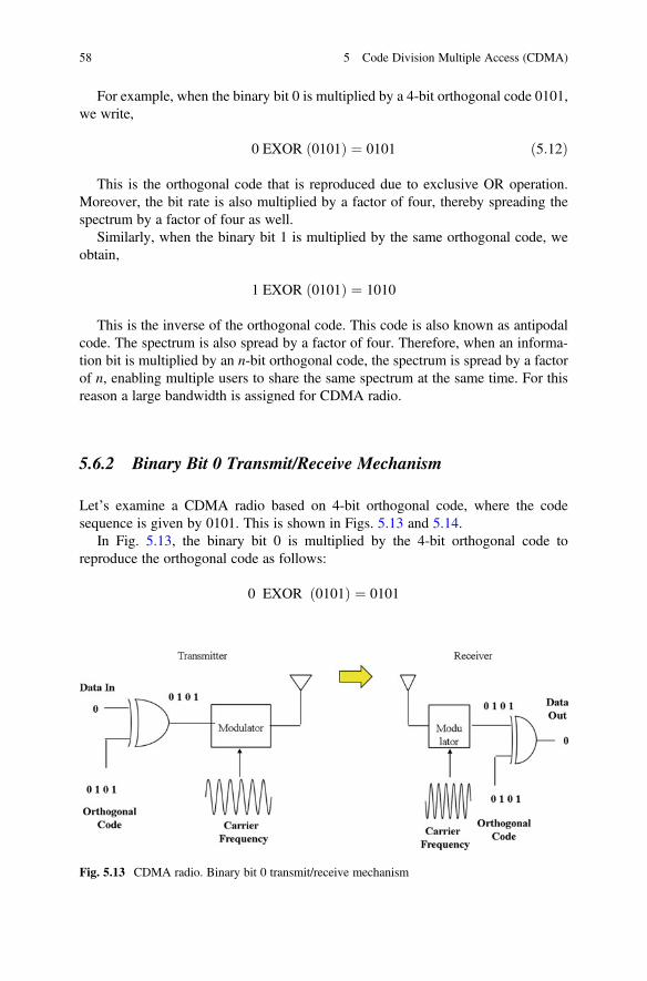
For example, when the binary bit 0 is multiplied by a 4-bit orthogonal code 0101,we write,
0 EXOR 0101ð Þ ¼ 0101 ð5:12Þ
This is the orthogonal code that is reproduced due to exclusive OR operation.Moreover, the bit rate is also multiplied by a factor of four, thereby spreading thespectrum by a factor of four as well.
Similarly, when the binary bit 1 is multiplied by the same orthogonal code, weobtain,
1 EXOR 0101ð Þ ¼ 1010
This is the inverse of the orthogonal code. This code is also known as antipodalcode. The spectrum is also spread by a factor of four. Therefore, when an informa-tion bit is multiplied by an n-bit orthogonal code, the spectrum is spread by a factorof n, enabling multiple users to share the same spectrum at the same time. For thisreason a large bandwidth is assigned for CDMA radio.
5.6.2 Binary Bit 0 Transmit/Receive Mechanism
Let’s examine a CDMA radio based on 4-bit orthogonal code, where the codesequence is given by 0101. This is shown in Figs. 5.13 and 5.14.
In Fig. 5.13, the binary bit 0 is multiplied by the 4-bit orthogonal code toreproduce the orthogonal code as follows:
0 EXOR 0101ð Þ ¼ 0101
Fig. 5.13 CDMA radio. Binary bit 0 transmit/receive mechanism
58 5 Code Division Multiple Access (CDMA)

This represents the information bit 0, which is modulated and transmitted to thereceiver.
The receiver intercepts the modulated carrier frequency, demodulates andrecovers the orthogonal code 0101. Since the exclusive OR gate also uses thesame orthogonal code, we obtain,
0101 EXOR 0101ð Þ ¼ 0000 ð5:13Þ
This represents the original binary value 0.
5.6.3 Binary Bit 1 Transmit/Receive Mechanism
Similarly, in Fig. 5.14, the binary bit 1 is multiplied by the same 4-bit orthogonalcode to produce the antipodal code as follows:
1 EXOR 0101ð Þ ¼ 1010
This represents the information bit 1, which is modulated and transmitted to thereceiver.
The receiver intercepts the modulated carrier frequency, demodulates andrecovers the antipodal code 1010. Since the exclusive OR gate uses the sameorthogonal code, we obtain,
1010 EXOR 0101ð Þ ¼ 1111 ð5:14Þ
This represents the original binary value 1.In summary, CDMA is a branch of multiple access technique, where multiple
users have access to the same spectrum through orthogonal codes. Orthogonal codes
Fig. 5.14 CDMA radio. Binary bit 1 transmit/receive mechanism
5.6 Construction of CDMA Radio 59
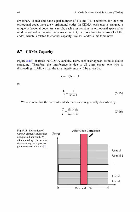
are binary valued and have equal number of 1’s and 0’s. Therefore, for an n-bitorthogonal code, there are n-orthogonal codes. In CDMA, each user is assigned aunique orthogonal code. As a result, each user remains in orthogonal space aftermodulation and offers maximum isolation. Yet, there is a limit to the use of all thecodes, which is related to channel capacity. We will address this topic next.
5.7 CDMA Capacity
Figure 5.15 illustrates the CDMA capacity. Here, each user appears as noise due tospreading. Therefore, the interference is due to all users except one who isdispreading. It follows that the total interference will be given by:
I ¼ C N � 1ð Þ
or
C
I¼ 1
N � 1ð5:15Þ
We also note that the carrier-to-interference ratio is generally described by:
C
I¼ Rb � Eb
No �Wð5:16Þ
Fig. 5.15 Illustration ofCDMA capacity. Each useroccupies a bandwidth Wafter spreading. One who isde-spreading has a processgain to recover the data [5]
60 5 Code Division Multiple Access (CDMA)

where:
• Eb ¼ energy per bit• Rb ¼ bit rate• No ¼ thermal noise• W ¼ bandwidth after spreading
Equating (5.15) and (5.16) we get
1N � 1
¼ Rb � Eb
No �Wð5:17Þ
Solving for the CDMA capacity N, we obtain,
N ¼ 1þ W=Rb
Eb=Noð5:18Þ
In the above capacity equation, the bandwidth after spreading relates to orthog-onal code. Therefore, we can write,
• W ¼ 2Rc
• Rc ¼ code rateð5:19Þ
The CDMA capacity then becomes,
N ¼ 1þ 2Rc þ Rb
Eb=No
In terms of code length n, the capacity equation can be further modifies as,
N ¼ 1þ 2nEb=No
ð5:20Þ
In the above equation, n is the code length, and N is the total number of users thatcan share the same bandwidth, using an n-bit orthogonal code. Table 5.2 shows theestimates of CDMA capacity for various code lengths.
It may be noted that the process gain alone is not responsible for the overallsystem performance and capacity. Other factors such as error control coding, cell site
Table 5.2 CDMA capacity for various code lengths
Code length (n) Eb/No (dB)Eb/N(linear) CDMA capacity (N )
4 6 3.98107171 3.009509
8 6 3.98107171 5.019018
16 6 3.98107171 9.038037
32 6 3.98107171 17.07607
64 6 3.98107171 33.15215
5.7 CDMA Capacity 61

deployment, antenna directivity and down tilt, sectorization, frequency reuse, etc.play important roles in enhancing the overall performance and capacity of theCDMA system.
5.8 Conclusions
This chapter presents a brief overview of spread spectrum CDMA radio. Spreadingand dispreading techniques are described with illustrations to show how it relates tospread spectrum CDMA radio. Orthogonal codes and their properties are presentedand show how Orthogonal Codes are generated and used to design CDMA radio.CDMA channel capacity is derived as a function of code length. Since CDMA is anoise-limited system, the need for power control is described to resolve the near-farproblems.
References
1. IS-95. (1993, March 15). Mobile station – Base station compatibility standard for dual modewide band spread spectrum cellular systems (TR 55, PN-3115).
2. Qualcomm. (1993). The CDMA network engineering handbook: Concepts in CDMA (Vol. 1).Qualcom, California, U.S.A.
3. Yang, S. C. (1998). CDMA RF system engineering. Norwood, MA: Artech House.4. Garg, V. K. (1999). IS-95 CDMA and cdma 2000. Upper Saddle River, NJ: Prentice Hall.5. Faruque, S. (1996). Cellular mobile systems engineering. Boston: Artech House.
62 5 Code Division Multiple Access (CDMA)

Chapter 6Orthogonal Frequency Division MultipleAccess (OFDMA)
Abstract This chapter presents a brief overview of the OFDMA technique used in4G WiMAX (Worldwide Interoperability for Microwave Access) and 4G LTE(Long-Term Evolution) cellular system. It is shown that OFDMA is an extensionof FDMA, where each frequency band is placed at the null of the adjacent frequencyband. This is governed by the well-known “Fourier transform,” so that adjacentfrequency bands are orthogonal to each other. OFDMA is a full-duplex communi-cation system. The communication link is maintained in both directions in the timedomain known as time division duplex (TDD). Numerous illustrations are used tobring students up to date in key concepts, underlying principles, and practicalapplications of “Fourier transform,” spectrum, and orthogonal properties of spec-trum, leading to OFDMA. Construction of OFDMA channels from theFCC-allocated band is presented to illustrate the concept.
Objectives
• Introduce OFDMA and show how it relates to FDMA.• Review Fourier transform and derive spectral response of data.• Recognize orthogonal signals and derive OFDMA channels from FCC-allocated
frequency band.• Design OFDMA radio and show spectrum allocation scheme.• Review TDD and show how TDD is used in OFDMA.
6.1 Introduction to OFDMA
Multiple access technique is well known in cellular communications [1–6]. Itenables many users to share the same spectrum in the frequency domain, timedomain, code domain, or phase domain. It begins with a frequency band, allocatedby FCC (Federal Communications Commission) [8]. FCC provides licenses tooperate wireless communication systems over given bands of frequencies. These
© The Author(s), under exclusive license to Springer Nature Switzerland AG. 2019S. Faruque, Radio Frequency Multiple Access Techniques Made Easy,SpringerBriefs in Electrical and Computer Engineering,https://doi.org/10.1007/978-3-319-91651-4_6
63

bands of frequencies are finite and have to be further divided into smaller bands(channels) and reused to provide services to other users. This is governed by theInternational Telecommunication Union (ITU) [9]. ITU generates standards such asFDMA, TDMA, CDMA, OFDMA, etc. for wireless communications.
Figure 6.1 illustrates the role of FCC-allocated spectrum and shows howOFDMA is derived from FDMA.
In FDMA (frequency division multiple access) [1–3], a carrier frequency isassigned to a single user. In this scheme, the channel is occupied by a single userfor the entire duration of the call. FDMA is the multiple access technique used inAMPS (Advanced Mobile Phone System), also known as first-generation(1G) cellular communication system.
OFDMA (orthogonal frequency division multiple access) [6, 7] is an extension ofFDMA, where each frequency is placed at the null of the adjacent frequency (seeFig. 6.1). This is governed by the well-known “Fourier transform,” so that adjacentfrequencies are orthogonal to each other. It begins with a band of frequencies. Thisband of frequencies is allocated by the FCC (Federal Communications Commis-sion). This band of frequency is further divided into several narrow bands offrequencies, where each frequency is orthogonal to each other. OFDMA is a full-duplex communication system. The communication link is maintained in bothdirections in the time domain known as time division duplex (TDD).
OFDMA is a relatively new wireless communication standard used in 4GWiMAX (Worldwide Interoperability for Microwave Access) and 4G LTE (Long-Term Evolution) protocol. It may be noted that WiMAX is an IEEE 802.16 standard,while LTE is a standard developed by the 3GPP group. Both standards are surpris-ingly similar and bandwidth efficient. OFDMA is used in 4G cellular standard.
In any multiple access technique, multiple users have access to the same spec-trum, so that the occupied bandwidth does not exceed the FCC-allocated channel.Furthermore, as the size and speed of digital data networks continue to expand,bandwidth efficiency becomes increasingly important. This is especially true forbroadband communication, where the choice of modulation schemes is importantkeeping in mind the available bandwidth resources, allocated by the FCC. With theseconstraints in mind, this chapter will present a brief overview of the OFDMAtechnique used in 4G cellular communication systems. Numerous illustrations will
OFDMA
FDMA
FCC Allocated Frequency Band
Frequency
Frequency
Frequency
Fig. 6.1 Illustration ofFCC-allocated spectrumshowing how OFDMA isderived from FDMA
64 6 Orthogonal Frequency Division Multiple Access (OFDMA)
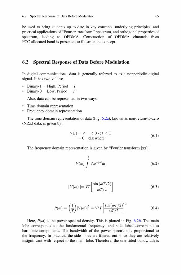
be used to bring students up to date in key concepts, underlying principles, andpractical applications of “Fourier transform,” spectrum, and orthogonal properties ofspectrum, leading to OFDMA. Construction of OFDMA channels fromFCC-allocated band is presented to illustrate the concept.
6.2 Spectral Response of Data Before Modulation
In digital communications, data is generally referred to as a nonperiodic digitalsignal. It has two values:
• Binary-1 ¼ High, Period ¼ T• Binary-0 ¼ Low, Period ¼ T
Also, data can be represented in two ways:
• Time domain representation• Frequency domain representation
The time domain representation of data (Fig. 6.2a), known as non-return-to-zero(NRZ) data, is given by:
V tð Þ ¼ V < 0 < t < T¼ 0 elsewhere
ð6:1Þ
The frequency domain representation is given by “Fourier transform [xx]”:
V ωð ÞZT
0
V :e�jωtdt ð6:2Þ
j V ωð Þ j¼ VTsin ωT=2ð ÞωT=2
� �ð6:3Þ
P ωð Þ ¼ 1T
� �V ωð Þj j2 ¼ V2T
sin ωT=2ð ÞωT=2
� �2ð6:4Þ
Here, P(ω) is the power spectral density. This is plotted in Fig. 6.2b. The mainlobe corresponds to the fundamental frequency, and side lobes correspond toharmonic components. The bandwidth of the power spectrum is proportional tothe frequency. In practice, the side lobes are filtered out since they are relativelyinsignificant with respect to the main lobe. Therefore, the one-sided bandwidth is
6.2 Spectral Response of Data Before Modulation 65

given by the ratio f/fb ¼ 1. In other words, the one-sided bandwidth ¼ f ¼ fb, wherefb ¼ Rb ¼ 1/T, T being the bit duration.
The general equation for two-sided response is given by:
V ωð Þ ¼Z/
�/V tð Þ:e�jωtdt ð6:5Þ
In this case, V(ω) is called two-sided spectrum of V(t).This is due to both positiveand negative frequencies used in the integral. The function can be a voltage or acurrent. Figure 6.2c shows the two-sided response, where the bandwidth is deter-mined by the main lobe.
Notice the two nulls before and after the main lobe. These nulls are the location ofadjacent channels. These nulls are also recognized as “orthogonal” frequencies as weshall see it later. We will now take ASK and BPSK modulation schemes to examinethe shifting properties of spectral response of data after modulation.
Fig. 6.2 (a) Discrete time digital signal and (b) its one-sided power spectral density and (c)two-sided power spectral density. The bandwidth associated with the non-return-to-zero (NRz)data is 2Rb, where Rb is the bit rate
66 6 Orthogonal Frequency Division Multiple Access (OFDMA)

6.3 Spectral Response of Data After Modulation
Spectral response of data after modulation depends on the bit rate and the modulationtype [10–12]. We will examine this by means of NRZ data and MPSK modulationwith M ¼ 2, 4, 8, etc. and evaluate the corresponding transmission bandwidth andOFDMA spectrum.
6.3.1 Spectral Response After BPSK Modulation
In BPSK, the phase of the carrier changes in two discrete levels, in accordance to theinput signal. We can represent this by means of a signal constellation diagram withM ¼ 2, 1 bit per phase. This is shown in Fig. 6.3, where the input raw data, having abit rate Rb1, is encoded by means of a rate r encoder. The encoded data, having a bitrate Rb2¼ Rb1/r (r < 1), is modulated by the BPSK modulator as shown in the figure.
The BPSK modulator takes one bit at a time to construct the phase constellationhaving two phases, also known as “symbols,” where each symbol represents 1 bit.The symbol rate is therefore the same as the encoded bit rate Rb2.
Therefore, the BPSK modulator has the following specifications:
• Two phases or two symbols• 1 bit/symbol
Figure 6.4 shows the spectral response of the BPSK modulator. Since there aretwo phases, the carrier frequency changes in two discrete levels, 1 bit per phase, as
Rb1(bits/s)
Rb2=Rb1/r(bits/s)
BPSK
S(t)
Two phases1 bit/phase
C(t)
01
EncoderRate = r
r < 1
Fig. 6.3 BPSK signal constellation having two symbols, 1 bit per symbol
6.3 Spectral Response of Data After Modulation 67
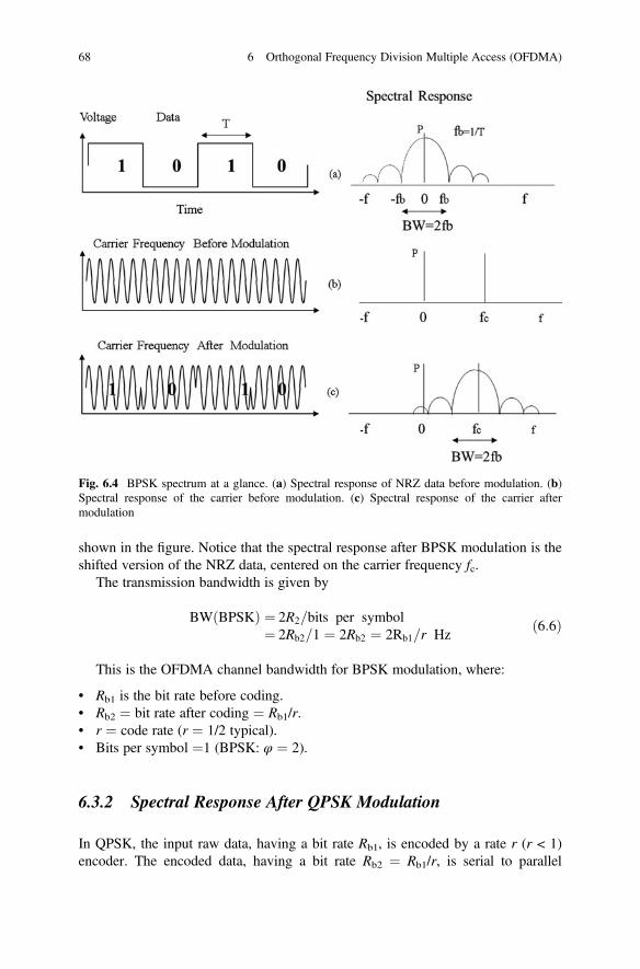
shown in the figure. Notice that the spectral response after BPSK modulation is theshifted version of the NRZ data, centered on the carrier frequency fc.
The transmission bandwidth is given by
BW BPSKð Þ ¼ 2R2=bits per symbol¼ 2Rb2=1 ¼ 2Rb2 ¼ 2Rb1=r Hz
ð6:6Þ
This is the OFDMA channel bandwidth for BPSK modulation, where:
• Rb1 is the bit rate before coding.• Rb2 ¼ bit rate after coding ¼ Rb1/r.• r ¼ code rate (r ¼ 1/2 typical).• Bits per symbol ¼1 (BPSK: φ ¼ 2).
6.3.2 Spectral Response After QPSK Modulation
In QPSK, the input raw data, having a bit rate Rb1, is encoded by a rate r (r < 1)encoder. The encoded data, having a bit rate Rb2 ¼ Rb1/r, is serial to parallel
Fig. 6.4 BPSK spectrum at a glance. (a) Spectral response of NRZ data before modulation. (b)Spectral response of the carrier before modulation. (c) Spectral response of the carrier aftermodulation
68 6 Orthogonal Frequency Division Multiple Access (OFDMA)

converted into two parallel bit streams. The encoded bit rate, now reduced in speedby a factor of two, is modulated by the QPSK modulator as shown in Fig. 6.5.
The QPSK modulator takes one bit from each stream to construct the phaseconstellation having four phases, also known as “symbols,” where each symbolrepresents 2 bits. The symbol rate is therefore reduced by a factor of two. The QPSKmodulator has four phases or four symbols, 2 bits/symbol, as shown in the figure.
Therefore, the QPSK modulator has the following specifications:
• Four phases or four symbols• 2 bits/symbol
The transmission bandwidth is given by
BW QPSKð Þ ¼ 2R2=bits per symbol¼ 2Rb2=2 ¼ Rb2 ¼ Rb1=r Hz
ð6:7Þ
This is the OFDMA channel bandwidth for QPSK modulation, where:
• Rb1 is the bit rate before coding.• Rb2 ¼ bit rate after coding ¼ Rb1/r.• r ¼ code rate (r ¼ 1/2 typical).• Bits per symbol ¼ 2 (QPSK: φ ¼ 4).
6.3.3 Spectral Response After 8PSK Modulation
In 8PSK, the input raw data, having a bit rate Rb1, is encoded by a rate r (r < 1)encoder. The encoded data, having a bit rate Rb2 ¼ Rb1/r, is serial to parallel
Rb1(bits/s)
Rb2=Rb1/r(bits/s)
Rb2/2(bits/s)
QPSK
EncoderRate = r
r < 11:2
S/P S(t)
Four phases2 bits/phase
C(t)
10
0001
11
Fig. 6.5 QPSK signal constellation having four symbols, 2 bits per symbol
6.3 Spectral Response of Data After Modulation 69

converted into three parallel streams. The encoded bit rate, now reduced in speed bya factor of three, is modulated by the 8PSK modulator as shown in Fig. 6.6.
The 8PSK modulator takes one bit from each stream to construct the phaseconstellation having 8 phases, also known as “Symbols”, where each symbolrepresents 3 bits. The symbol rate is therefore reduced by a factor of 3. The 8PSKmodulator has 8 phases or 8 symbols, 3 bits/symbol, as shown in the figure.
Therefore, the 8PSK modulator has the following specifications:
• Eight phases or eight symbols• 3 bits/symbol
The transmission bandwidth is given by
BW 8PSKð Þ ¼ 2R2=bits per symbol¼ 2Rb2=3 ¼ 2=3ð ÞRb2 ¼ 2=3ð ÞRb1=r Hz
ð6:8Þ
This is the OFDMA channel bandwidth for 8PSK modulation, where:
• Rb1 is the bit rate before coding.• Rb2 ¼ bit rate after coding ¼ Rb1/r.• r ¼ code rate (r ¼ 1/2 typical).• Bits per symbol ¼ 3 (8PSK: φ ¼ 8).
6.3.4 Spectral Response After 16PSK Modulation
In 16PSK, the input raw data, having a bit rate Rb1, is encoded by means of a rater (r < 1) encoder. The encoded data, having a bit rate Rb2 ¼ Rb1/r, is serial to parallel
Rb1(bits/s)
Rb2=Rb1/r(bits/s)
Rb2=/3(bits/s)
S/P
1:3
EncoderRate = r
r < 1
8PSK
010
001
S(t)
8 Phases3 bits/phase
000
100101
011
C(t)
110
111
011
Fig. 6.6 8PSK signal constellation having eight symbols, 3 bits per symbol
70 6 Orthogonal Frequency Division Multiple Access (OFDMA)

converted into four parallel streams. The encoded bit rate, now reduced in speed by afactor of four, is modulated by the 16PSK modulator as shown in Fig. 6.7.
The 16PSK modulator takes 1 bit from each stream to construct the phaseconstellation having 16 phases, also known as “symbols,” where each symbolrepresents four bits. The symbol rate is therefore reduced by a factor of four.Therefore, the 16PSK modulator has 16 phases or 16 symbols, 4 bits/symbol, asshown in the figure.
Therefore, the 16PSK modulator has the following specifications:
• 16 phases or 16 symbols• 4 bits/symbol
The transmission bandwidth is given by
BW 16PSKð Þ ¼ 2R2=bits per symbol¼ 2Rb2=4 ¼ 1=2ð ÞRb2 ¼ 1=2ð ÞRb1=r Hz
ð6:9Þ
This is the OFDMA channel bandwidth for 16PSK modulation, where:
• Rb1 is the bit rate before coding.• Rb2 ¼ bit rate after coding ¼ Rb1/r.• r ¼ code rate (r ¼ 1/2 typical).• Bits per symbol ¼ 4 (8PSK: φ ¼ 16).
Rb1(bits/s)
Rb2=Rb1/r(bits/s)
Rb2=/4(bits/s)
16PSK
S(t)
16 Phases4 bits/phase
C(t)
EncoderRate = r
r < 1
S/P
1:4
Fig. 6.7 16 PSK signal constellation having 16 symbols, 4 bits per symbol. Here, each symbol isrepresented by a dot, where each dot represents 4 bits
6.3 Spectral Response of Data After Modulation 71

6.4 Construction of OFDMA Channels
Stated earlier, OFDMA channels are constructed from FDMA channels. It beginswith a wide frequency band, allocated by the FCC (Federal CommunicationsCommission). In this scheme, shown in Fig. 6.8, the FCC-allocated frequencyband is divided into several smaller frequency bands known as FDMA channels.The bandwidth of each FDMA channel is determined by the main lobe of the powerspectral density, which is governed by the input coded bit rate and the modulationtype. The bandwidth is defined by the first null to first null of the two-sided responseof the main lobe.
In OFDMA, each frequency band is placed at the null of the adjacent band asshown in Fig. 6.8. Notice that there are n � 1 nulls in the OFDMA spectrum, wheren is the number of FDMA channels. Therefore, the number of OFDMA channels willbe given by
Number of OFDMA channels ¼ 2� FDMA channels� 1 ð6:10Þ
Let’s examine this by means of the following problems:
Problem 1In this problem we will construct OFDMA channels from a given FCC- allocatedfrequency band with the following design parameters:
Given:• FCC-allocated band ¼ 20 MHz• Input bit rate before coding Rb1 ¼ 1 MHz• Rate ½ convolutional Coding (r ¼ 1/2)• QPSK modulationFind:• Bit rate after coding Rb2
Fig. 6.8 Construction of OFDMA channels from FCC-allocated frequency band. There are n � 1nulls in the FCC-allocated band, where n is the number of FDMA channels
72 6 Orthogonal Frequency Division Multiple Access (OFDMA)

• The required channel bandwidth BW• Number of FDMA channels available• Number of OFDMA channels available
Solution:• Bit rate after coding Rb2 ¼ Rb1/r ¼ 2Rb1 ¼ 2 � 1 Mbps ¼ 2 Mbps.• BW(QPSK) ¼ 2Rb2/bits per symbol ¼ 4 Mbps/2 ¼ 2 MHz.• Number of FDMA channels ¼ 20 MHz/BW ¼ 20 MHz/2 MHz ¼ 10 FDMA
channels (see figure below).• Number of OFDMA channels ¼ 2FDMA channels � 1 ¼ 20 � 1 ¼ 19 OFDMA
channels (see figure below).• Figure 6.9 illustrates the channel sets.
Problem 2Repeat the previous problem with 16 PSK modulation.
Given:• FCC-allocated band ¼ 20 MHz• Input bit rate before coding Rb1 ¼ 1 MHz• Rate ½ convolutional coding (r ¼ 1/2)• 16PSK modulationFind:• Bit rate after coding Rb2
• The required channel bandwidth BW• Number of FDMA channels available• Number of OFDMA channels available
Fig. 6.9 Construction of FDMA and OFDMA channels
6.4 Construction of OFDMA Channels 73
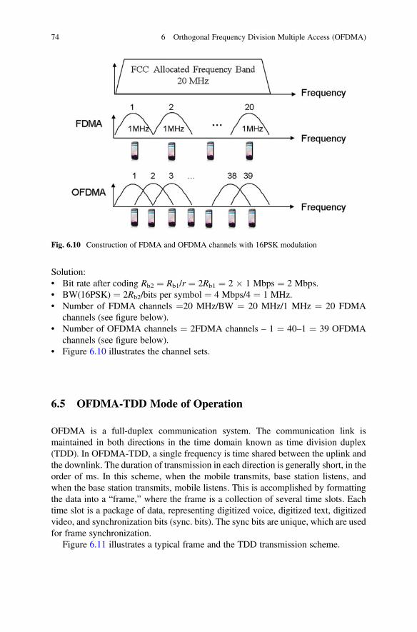
Solution:• Bit rate after coding Rb2 ¼ Rb1/r ¼ 2Rb1 ¼ 2 � 1 Mbps ¼ 2 Mbps.• BW(16PSK) ¼ 2Rb2/bits per symbol ¼ 4 Mbps/4 ¼ 1 MHz.• Number of FDMA channels ¼20 MHz/BW ¼ 20 MHz/1 MHz ¼ 20 FDMA
channels (see figure below).• Number of OFDMA channels ¼ 2FDMA channels – 1 ¼ 40–1 ¼ 39 OFDMA
channels (see figure below).• Figure 6.10 illustrates the channel sets.
6.5 OFDMA-TDD Mode of Operation
OFDMA is a full-duplex communication system. The communication link ismaintained in both directions in the time domain known as time division duplex(TDD). In OFDMA-TDD, a single frequency is time shared between the uplink andthe downlink. The duration of transmission in each direction is generally short, in theorder of ms. In this scheme, when the mobile transmits, base station listens, andwhen the base station transmits, mobile listens. This is accomplished by formattingthe data into a “frame,” where the frame is a collection of several time slots. Eachtime slot is a package of data, representing digitized voice, digitized text, digitizedvideo, and synchronization bits (sync. bits). The sync bits are unique, which are usedfor frame synchronization.
Figure 6.11 illustrates a typical frame and the TDD transmission scheme.
Fig. 6.10 Construction of FDMA and OFDMA channels with 16PSK modulation
74 6 Orthogonal Frequency Division Multiple Access (OFDMA)
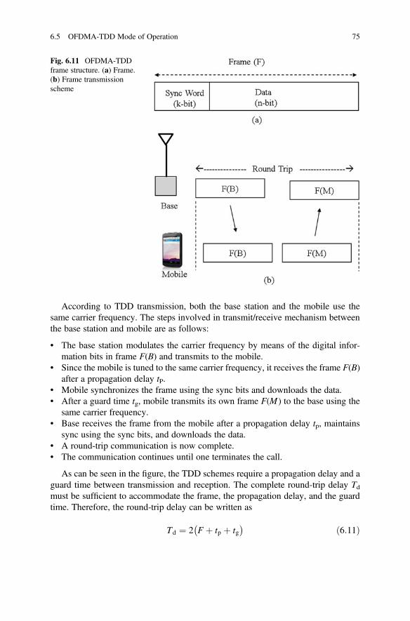
According to TDD transmission, both the base station and the mobile use thesame carrier frequency. The steps involved in transmit/receive mechanism betweenthe base station and mobile are as follows:
• The base station modulates the carrier frequency by means of the digital infor-mation bits in frame F(B) and transmits to the mobile.
• Since the mobile is tuned to the same carrier frequency, it receives the frame F(B)after a propagation delay tP.
• Mobile synchronizes the frame using the sync bits and downloads the data.• After a guard time tg, mobile transmits its own frame F(M ) to the base using the
same carrier frequency.• Base receives the frame from the mobile after a propagation delay tp, maintains
sync using the sync bits, and downloads the data.• A round-trip communication is now complete.• The communication continues until one terminates the call.
As can be seen in the figure, the TDD schemes require a propagation delay and aguard time between transmission and reception. The complete round-trip delay Tdmust be sufficient to accommodate the frame, the propagation delay, and the guardtime. Therefore, the round-trip delay can be written as
Td ¼ 2 F þ tp þ tg� � ð6:11Þ
Fig. 6.11 OFDMA-TDDframe structure. (a) Frame.(b) Frame transmissionscheme
6.5 OFDMA-TDD Mode of Operation 75
The round-trip delay Td depends on the frame length F, which is generally inmilliseconds (ms). The propagation delay tp depends on the propagation distance,and the guard time tg depends on the technology
Problem 3Given:• Frame length ¼ 2 ms• Guard time tg ¼0.01 ms• Distance between the base station and mobile ¼1 km• Velocity of light c ¼ 3 � 108 m/sFind:• The round-trip delay tp.
Solution:• Propagation delay for a distance of 1 km ¼ 1 km/(3 � 108 m) ¼ 3.3 ms• Round-trip delay td ¼ 2 (tp + tf + tg) ¼ 2(3.3 ms + 2 ms + 0.01 ms) ¼ 5.31 ms
6.6 Conclusions
This chapter presents a brief overview of the OFDMA technique used in 4GWiMAX (Worldwide Interoperability for Microwave Access) and 4G LTE (Long-Term Evolution) cellular system. It is shown that OFDMA is an extension of FDMA,where each frequency band is placed at the null of the adjacent band. This isgoverned by the well-known “Fourier transform,” so that adjacent bands are orthog-onal to each other. OFDMA is a full-duplex communication system. The commu-nication link is maintained in both directions in the time domain known as timedivision duplex (TDD). Numerous illustrations are used to bring students up to datein key concepts, underlying principles, and practical applications of “Fourier trans-form,” spectrum, and orthogonal properties of spectrum, leading to OFDMA. Con-struction of OFDMA channels from FCC-allocated band is presented to illustrate theconcept.
References
1. IS-54. (1989, December). “Dual-mode mobile station-base station compatibility standard(EIA/TIA Project Number 2215).
2. IS-95. (1993, March 15). “Mobile station – Base station compatibility standard for dual modewide band spread spectrum cellular systems (TR 45, PN-3115).
3. MacDonald, V. H. (1969, January). The cellular concept. The Bell System Technical Journal, 58(1).
4. Lee, W. C. Y. (1989). Mobile cellular telecommunications systems. New York: McGraw-Hill.5. Faruque, S. (1996). Cellular mobile systems engineering. Norwood, MA: Artech House. ISBN:
0-89006-518-6.
76 6 Orthogonal Frequency Division Multiple Access (OFDMA)

6. ITU-R. Requirements related to technical performance for IMT-advanced radio interface(s)(Report M.2134), Approved in November 2008.
7. Parkvall, S., & Astely, D. (2009, April). The evolution of LTE toward LTE Advanced. Journalof Communications, 4(3), 146–154. https://doi.org/10.4304/jcm.4.3.146-154.
8. FCC, Federal Communications Commission, Washington, DC.9. ITU, International Telecommunications Union, Paris, France.
10. Faruque, S. (2015). Radio frequency source coding made easy, Springer Briefs in Electrical andComputer Engineering (1st ed.). ISBN-13: 968-3319156088, ISBN-10: 331915608.
11. Faruque, S. (2016). Radio frequency channel coding made easy, Springer Briefs in Electricaland Computer Engineering (1st ed.). ISBN-13: 968-3319211695, ISBN-10: 3319211692.
12. Faruque, S. (2016). Radio frequency modulation made easy, Springer Briefs in Electrical andComputer Engineering (1st ed.). ISBN-13: 968-3319412009, ISBN-10: 3319412000.
References 77
Related Documents