1 Pelatnas IESO Geologi Struktur 2013 Pelatnas IESO Geologi Struktur 2013 Deformasi Liat Deformasi Liat Salahuddin Salahuddin Husein Husein Jurusan Jurusan Teknik Teknik Geologi Geologi Fakultas Fakultas Teknik Teknik Universitas Universitas Gadjah Gadjah Mada Mada 2013 2013

Welcome message from author
This document is posted to help you gain knowledge. Please leave a comment to let me know what you think about it! Share it to your friends and learn new things together.
Transcript
1
Pelatnas IESO Geologi Struktur 2013Pelatnas IESO Geologi Struktur 2013
Deformasi LiatDeformasi Liat
SalahuddinSalahuddin HuseinHusein
JurusanJurusan TeknikTeknik GeologiGeologiFakultasFakultas TeknikTeknik UniversitasUniversitas GadjahGadjah MadaMada
20132013
2
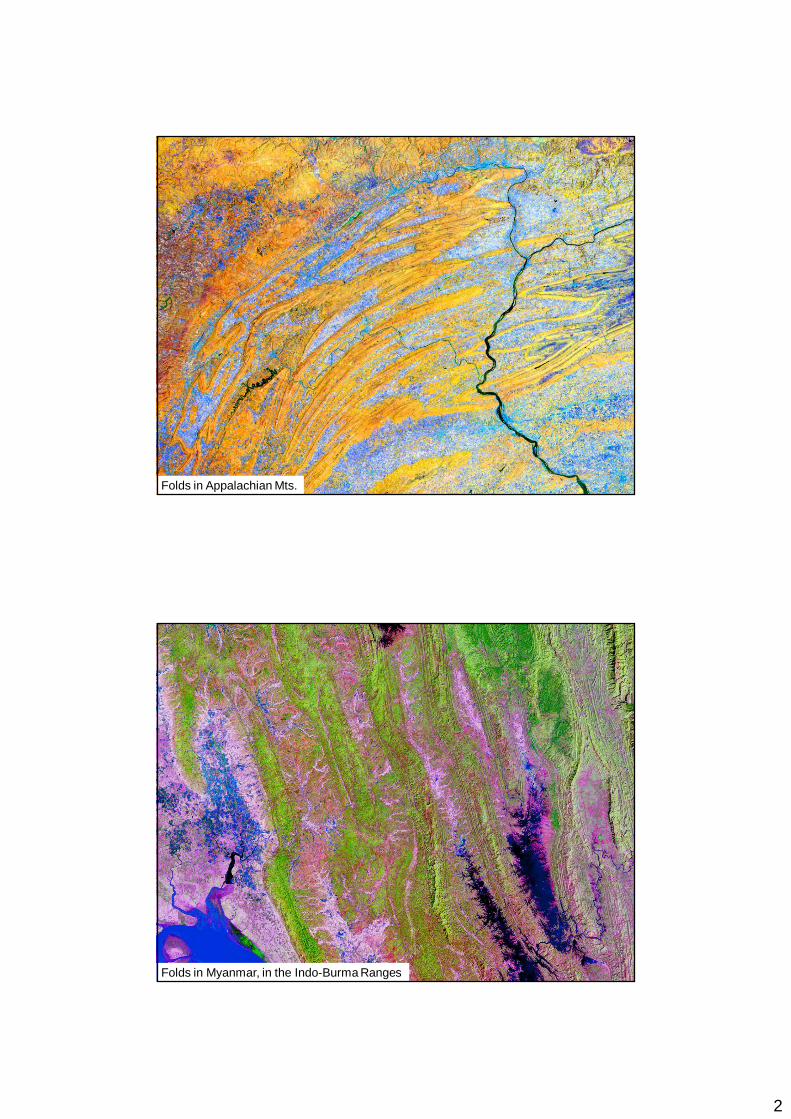
Folds in Appalachian Mts.
Folds in Myanmar, in the Indo-Burma Ranges
3
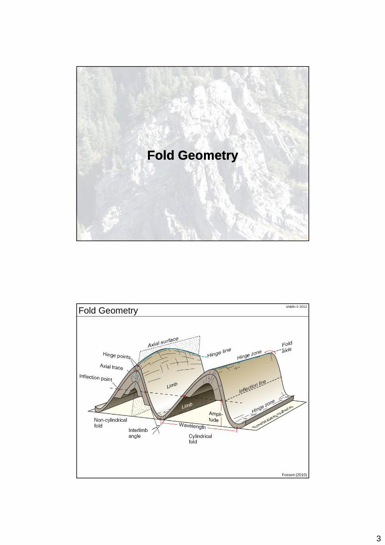
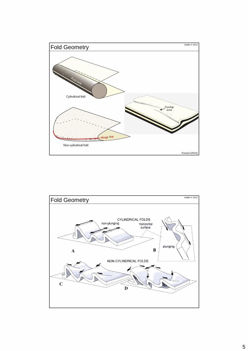
Fold GeometryFold Geometry
shddin © 2012Fold Geometry
Fossen (2010)
4
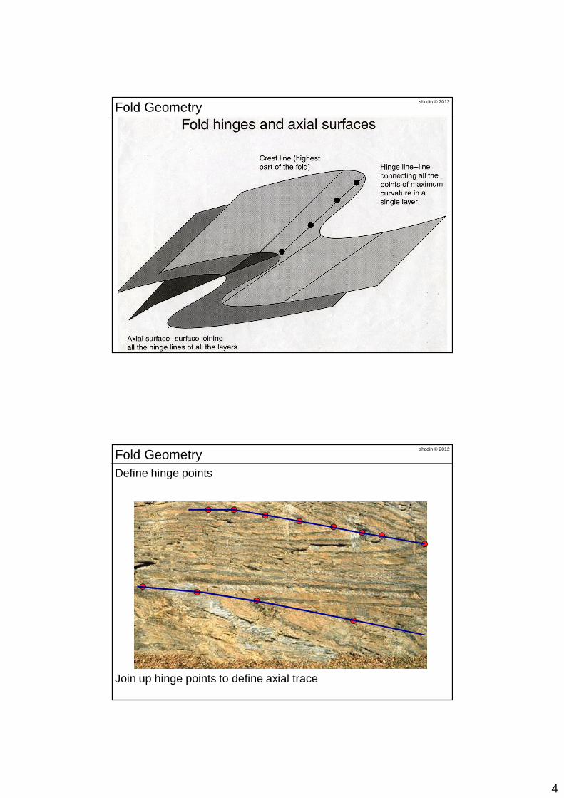
shddin © 2012Fold Geometry
Define hinge points
Join up hinge points to define axial trace
shddin © 2012Fold Geometry
5
shddin © 2012Fold Geometry
Fossen (2010)
shddin © 2012Fold Geometry
6
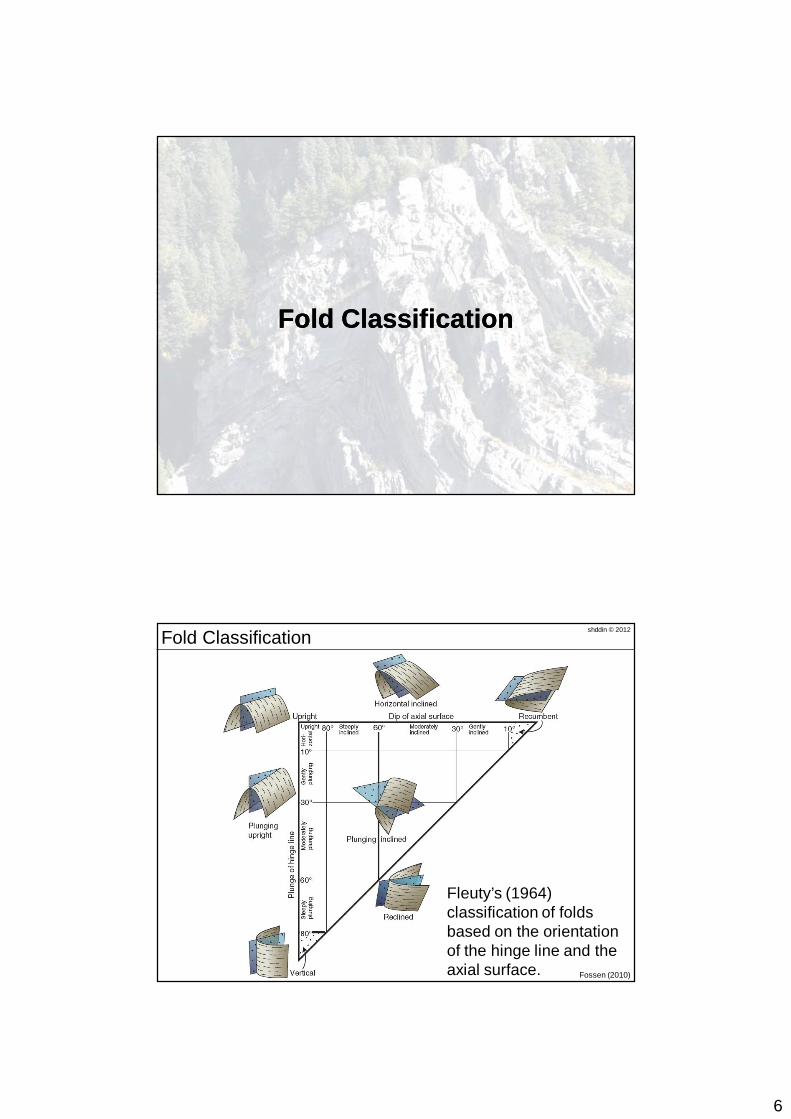
Fold ClassificationFold Classification
shddin © 2012Fold Classification
Fossen (2010)
Fleuty’s (1964) classification of folds based on the orientation of the hinge line and the axial surface.
7
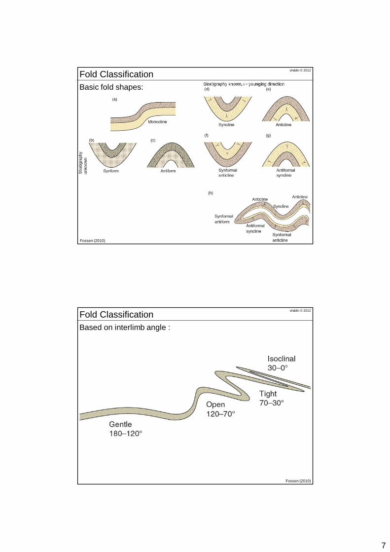
shddin © 2012Fold Classification
Fossen (2010)
Basic fold shapes:
shddin © 2012Fold Classification
Fossen (2010)
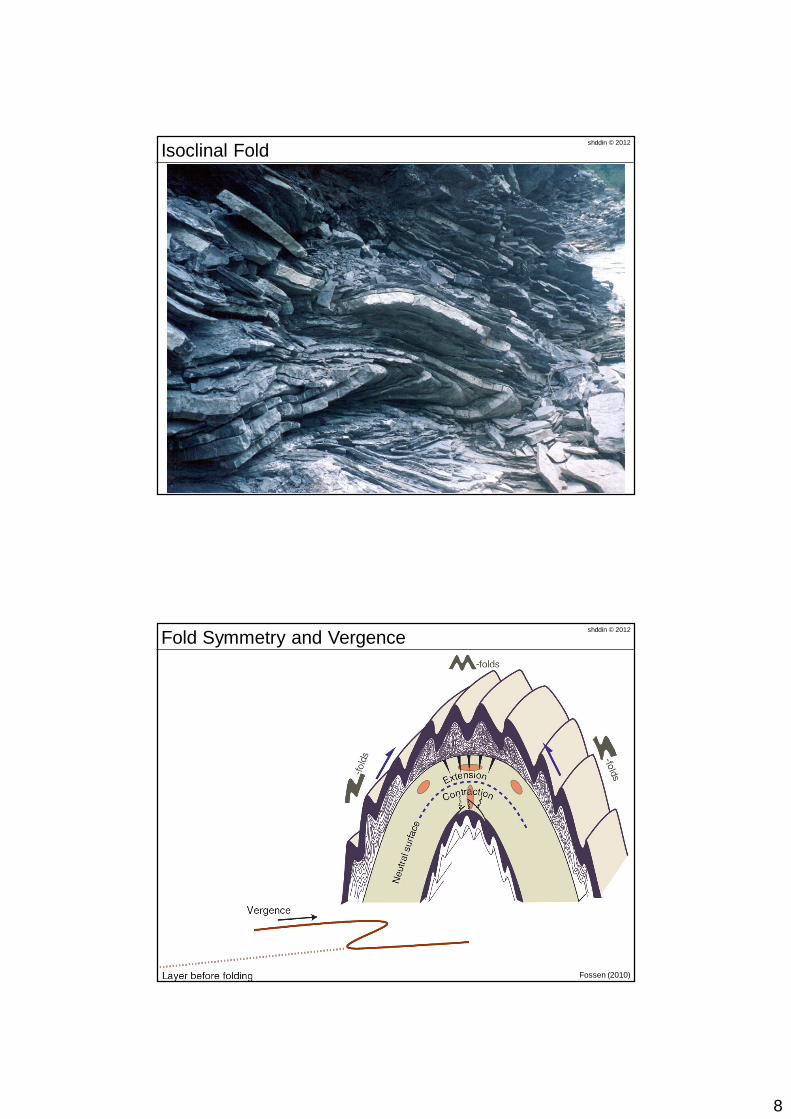
Based on interlimb angle :
8
shddin © 2012Isoclinal Fold
shddin © 2012Fold Symmetry and Vergence
Fossen (2010)
9
shddin © 2012Folding Mechanisms
Fossen (2010)
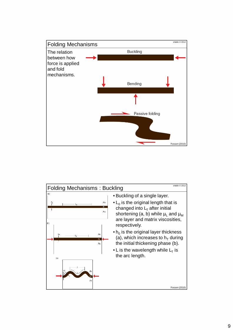
The relation between how force is applied and fold mechanisms.
shddin © 2012Folding Mechanisms : Buckling
Fossen (2010)
• Buckling of a single layer. • L0 is the original length that is
changed into LT after initial shortening (a, b) while µL and µMare layer and matrix viscosities, respectively.
• h0 is the original layer thickness (a), which increases to hT during the initial thickening phase (b).
• L is the wavelength while LT is the arc length.
10
shddin © 2012Folding Mechanisms : Buckling
Fossen (2010)
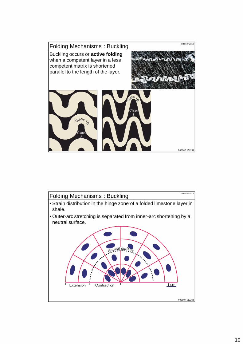
Buckling occurs or active foldingwhen a competent layer in a less competent matrix is shortened parallel to the length of the layer.
shddin © 2012Folding Mechanisms : Buckling
Fossen (2010)
• Strain distribution in the hinge zone of a folded limestone layer in shale.
• Outer-arc stretching is separated from inner-arc shortening by a neutral surface.
11
shddin © 2012Folding Mechanisms : Buckling
Fossen (2010)
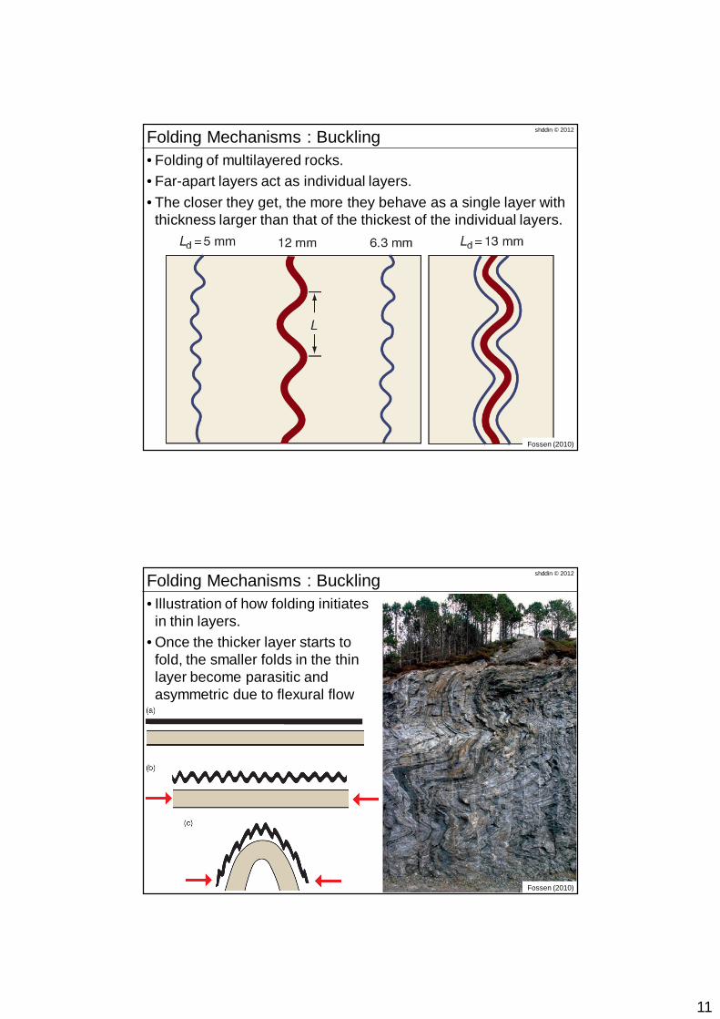
• Folding of multilayered rocks. • Far-apart layers act as individual layers. • The closer they get, the more they behave as a single layer with
thickness larger than that of the thickest of the individual layers.
shddin © 2012Folding Mechanisms : Buckling
Fossen (2010)
• Illustration of how folding initiates in thin layers.
• Once the thicker layer starts to fold, the smaller folds in the thin layer become parasitic and asymmetric due to flexural flow
12
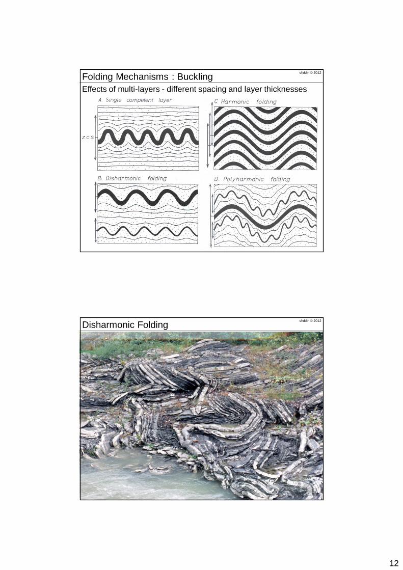
Effects of multi-layers - different spacing and layer thicknesses
shddin © 2012Folding Mechanisms : Buckling
shddin © 2012Disharmonic Folding
13
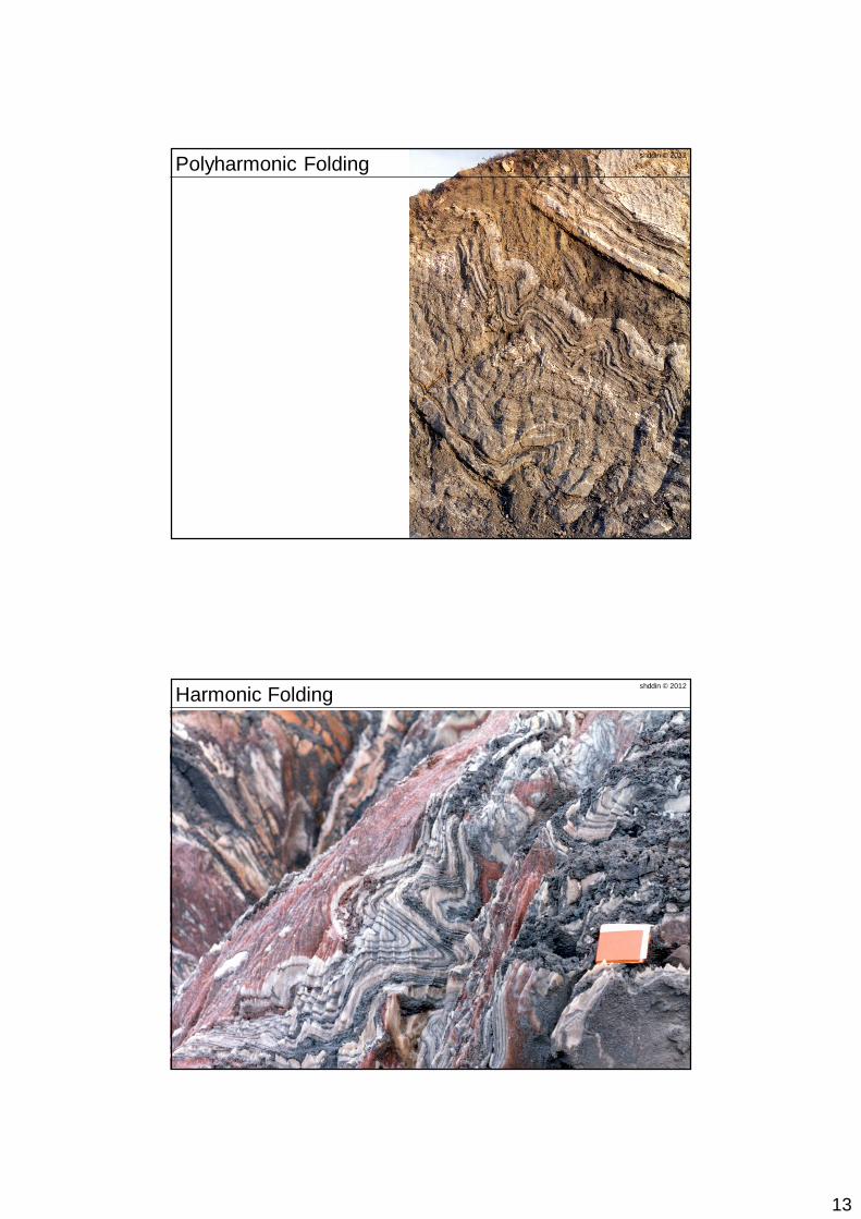
shddin © 2012Polyharmonic Folding
shddin © 2012Harmonic Folding
14
shddin © 2012Folding Mechanisms : Passive Folding
Fossen (2010)
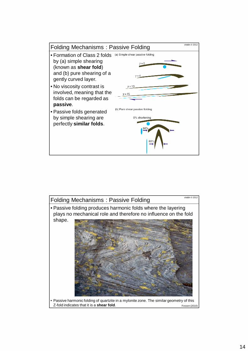
• Formation of Class 2 folds by (a) simple shearing (known as shear fold) and (b) pure shearing of a gently curved layer.
• No viscosity contrast is involved, meaning that the folds can be regarded as passive.
• Passive folds generated by simple shearing are perfectly similar folds.
shddin © 2012Folding Mechanisms : Passive Folding
Fossen (2010)
• Passive folding produces harmonic folds where the layering plays no mechanical role and therefore no influence on the fold shape.
• Passive harmonic folding of quartzite in a mylonite zone. The similar geometry of this Z-fold indicates that it is a shear fold.
15
shddin © 2012Folding Mechanisms : Bending
Fossen (2010)
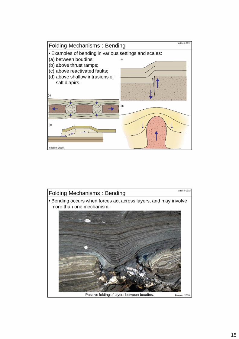
• Examples of bending in various settings and scales: (a) between boudins; (b) above thrust ramps; (c) above reactivated faults; (d) above shallow intrusions or
salt diapirs.
shddin © 2012Folding Mechanisms : Bending
Fossen (2010)
• Bending occurs when forces act across layers, and may involve more than one mechanism.
Passive folding of layers between boudins.
16
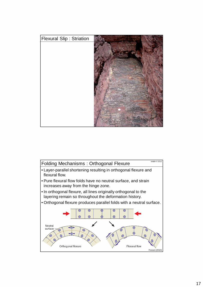
shddin © 2012Folding Mechanisms : Slip and Flow
Fossen (2010)
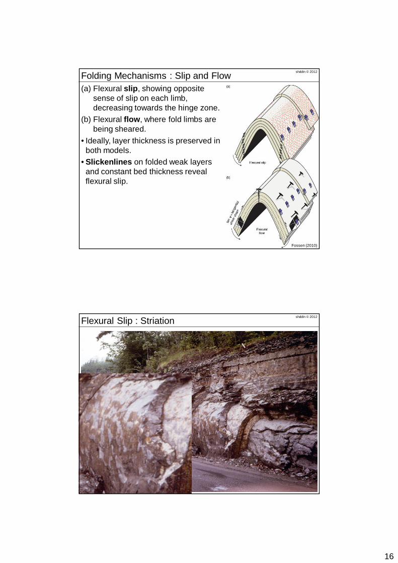
(a) Flexural slip, showing opposite sense of slip on each limb, decreasing towards the hinge zone.
(b) Flexural flow, where fold limbs are being sheared.
• Ideally, layer thickness is preserved in both models.
• Slickenlines on folded weak layers and constant bed thickness reveal flexural slip.
shddin © 2012Flexural Slip : Striation
17
shddin © 2012Flexural Slip : Striation
shddin © 2012Folding Mechanisms : Orthogonal Flexure
Fossen (2010)
• Layer-parallel shortening resulting in orthogonal flexure and flexural flow.
• Pure flexural flow folds have no neutral surface, and strain increases away from the hinge zone.
• In orthogonal flexure, all lines originally orthogonal to the layering remain so throughout the deformation history.
• Orthogonal flexure produces parallel folds with a neutral surface.
18
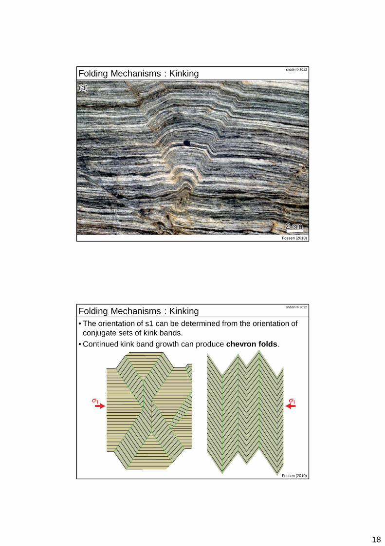
shddin © 2012Folding Mechanisms : Kinking
Fossen (2010)
shddin © 2012Folding Mechanisms : Kinking
Fossen (2010)
• The orientation of s1 can be determined from the orientation of conjugate sets of kink bands.
• Continued kink band growth can produce chevron folds.
19
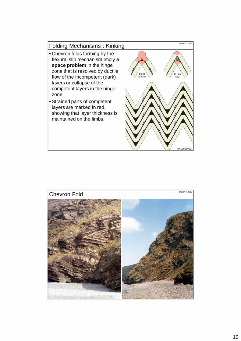
shddin © 2012Folding Mechanisms : Kinking
Fossen (2010)
• Chevron folds forming by the flexural slip mechanism imply a space problem in the hinge zone that is resolved by ductile flow of the incompetent (dark) layers or collapse of the competent layers in the hinge zone.
• Strained parts of competent layers are marked in red, showing that layer thickness is maintained on the limbs.
shddin © 2012Chevron Fold
20
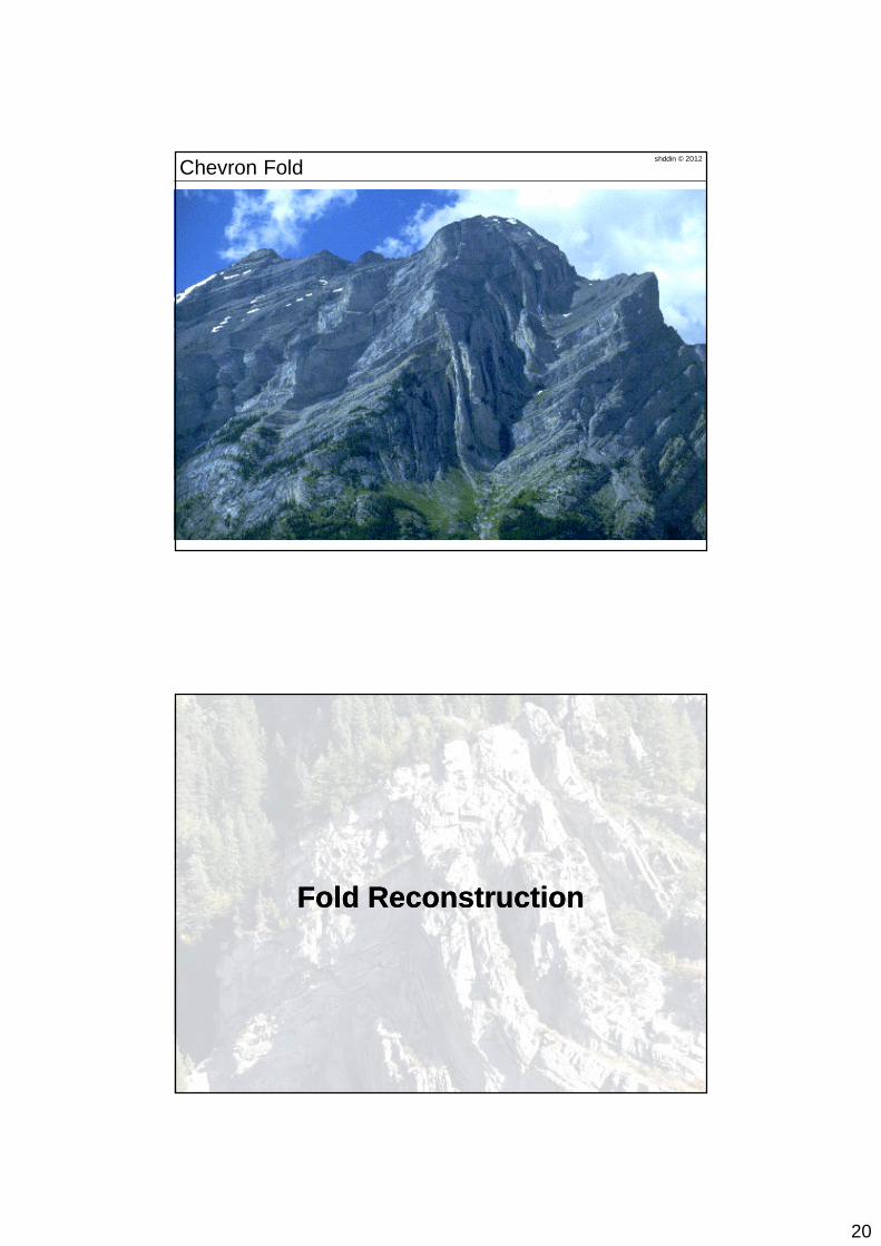
shddin © 2012Chevron Fold
Fold ReconstructionFold Reconstruction
21
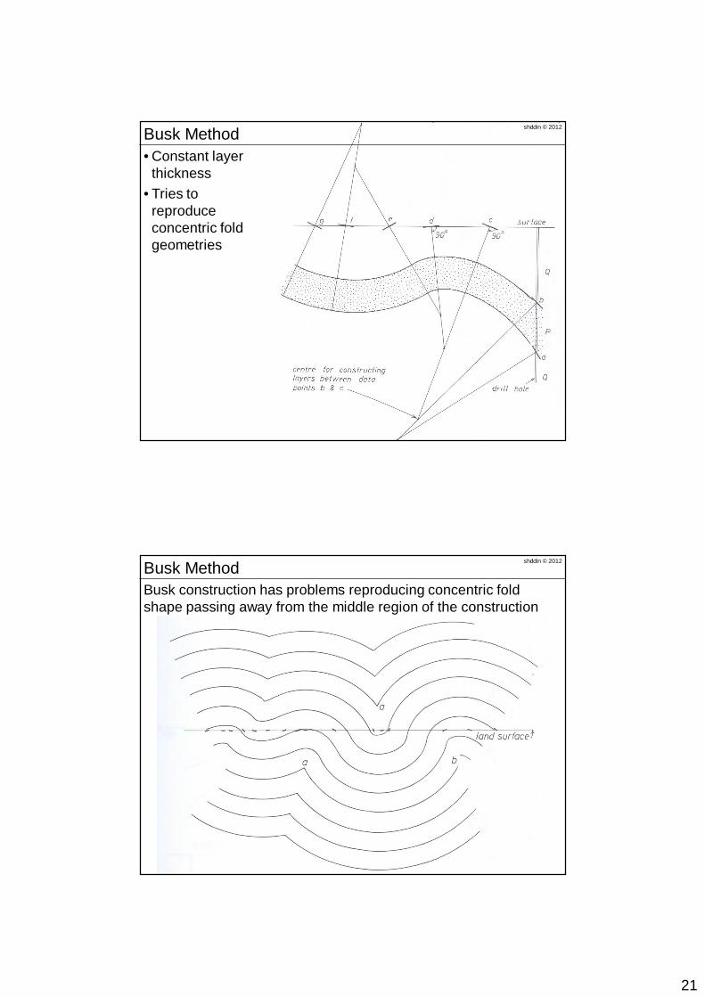
• Constant layer thickness
• Tries to reproduce concentric fold geometries
shddin © 2012Busk Method
Busk construction has problems reproducing concentric fold shape passing away from the middle region of the construction
shddin © 2012Busk Method
22
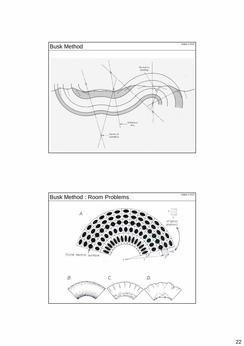
shddin © 2012Busk Method
shddin © 2012Busk Method : Room Problems
23
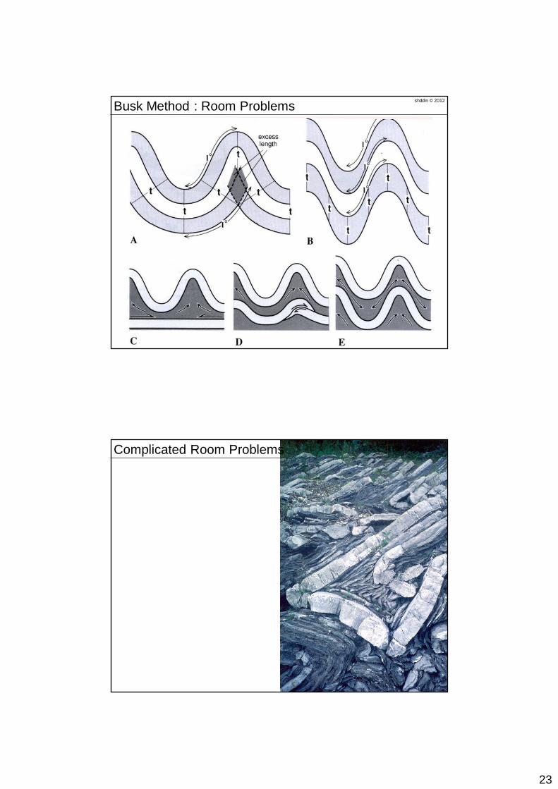
shddin © 2012Busk Method : Room Problems
shddin © 2012Complicated Room Problems
24
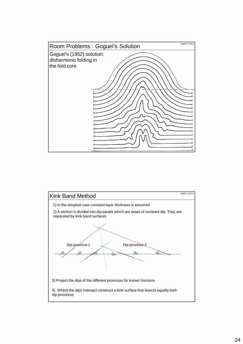
Goguel’s (1952) solution:disharmonic folding inthe fold core
shddin © 2012Room Problems : Goguel’s Solution
1) In the simplest case constant layer thickness is assumed
Dip province 1 Dip province 2
3) Project the dips of the different provinces for known horizons
2) A section is divided into dip panels which are areas of constant dip. They are separated by kink band surfaces
4) Where the dips intersect construct a kink surface that bisects equally both dip provinces
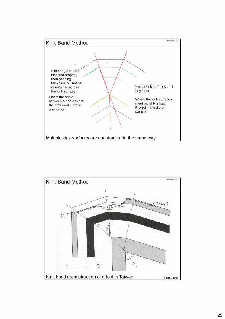
shddin © 2012Kink Band Method
25
Multiple kink surfaces are constructed in the same way
Project kink surfaces until they meet
a bc
ca
Where the kink surfaces meet panel b is lost.Project in the dip of panel a
Bisect the angle between a and c to get the new axial surface orientation
If the angle is not bisected properly then bedding thickness will not be maintained across the kink surface
shddin © 2012Kink Band Method
Kink band reconstruction of a fold in Taiwan
shddin © 2012Kink Band Method
(Suppe, 1988)
26
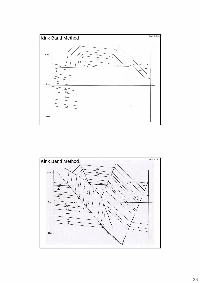
shddin © 2012Kink Band Method
shddin © 2012Kink Band Method
27
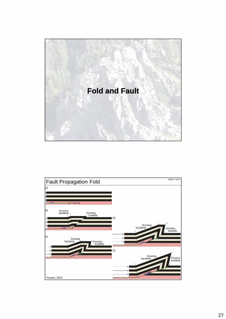
Fold and FaultFold and Fault
Fossen, 2010
shddin © 2012Fault Propagation Fold
28
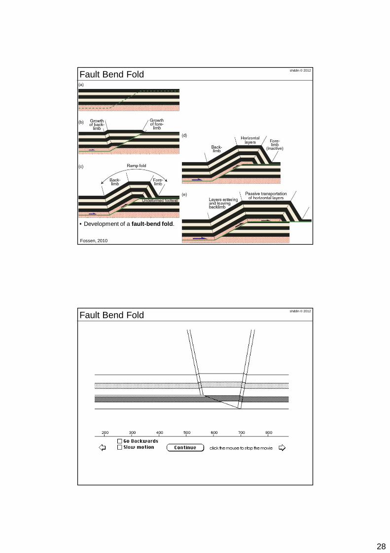
Fossen, 2010
• Development of a fault-bend fold.
shddin © 2012Fault Bend Fold
shddin © 2012Fault Bend Fold
29
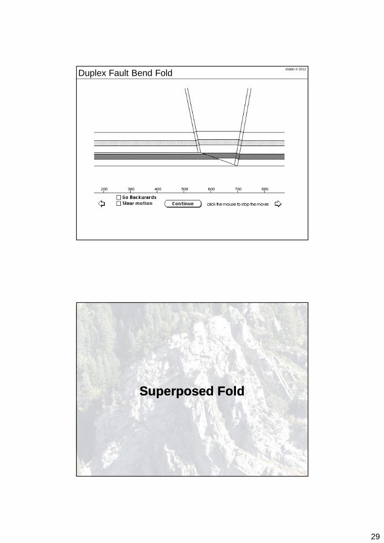
shddin © 2012Duplex Fault Bend Fold
Superposed FoldSuperposed Fold
30
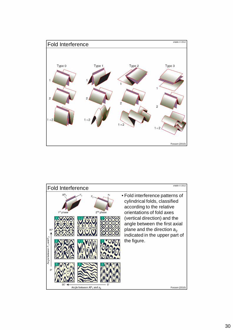
shddin © 2012Fold Interference
Fossen (2010)
shddin © 2012Fold Interference
Fossen (2010)
• Fold interference patterns of cylindrical folds, classified according to the relative orientations of fold axes (vertical direction) and the angle between the first axial plane and the direction a2indicated in the upper part of the figure.
31
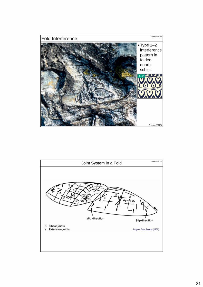
shddin © 2012Fold Interference• Type 1–2
interference pattern in foldedquartz schist.
Fossen (2010)
shddin © 2007Joint System in a Fold
Related Documents


![[Files.indowebster.com]-Geology Handout Geologi Dasar 2010 Salahuddin Hussein 2009](https://static.cupdf.com/doc/110x72/55cf9a1a550346d033a07c5a/filesindowebstercom-geology-handout-geologi-dasar-2010-salahuddin-hussein.jpg)